Embed Size (px)
Citation preview

T-6B JPPT 1542.166A
Simulator Event Briefing Guide
JPPT 1542.166A C2102
Sim
ula
tor
Event In
stru
cto
r Guid
e
PR
IMA
RY
AN
D IN
TE
RM
ED
IAT
E M
ULT
I-SE
RV
ICE
NF
O/W
SO
TR
AIN
ING
SY
ST
EM
Gra
din
g G
uid
elin
es –
I20
01
C2102 Briefing Guide
(Worksheet)
Planned Route:
Takeoff: KNSE, Rwy 05 Altitude: MOA Limits Route: North MOA Training Device: UTD/OFT
SYLLABUS NOTES: The student shall bring all required flight gear and practice strapping in on every event in this block
Students shall use an unaltered Quadfold NATOPS Checklist for all events in this block
Special Syllabus Requirement Loss of START READY light during start sequence
Discuss
a. All Normal Operating Procedures Ground (line area, taxing….) Reference FWOP, Contact FTI, Squadron SOP’s for further questions
b. Abnormal Starts
Hot Start (EICAS Video)
Hung Start (EICAS Video)
No Start (EICAS Video) Critical Action Items
c. Loss of START READY light during start sequence (EICAS Video) START READY light should remain on steady until PCL is advanced to idle. Action to take when START READY light goes out during start Critical Action Items
d. Engine Fire on Ground Indications (inside cockpit, lineman…) Procedural Steps
e. Emergency Engine Shutdown Reasons for emergency shutdown on the ground as per Flight Manual Critical Action Items
f. Emergency Ground Egress Procedural Steps Safety Precautions (CFS actuation, Ejection Seat…..)
Normal Start (EICAS Video)
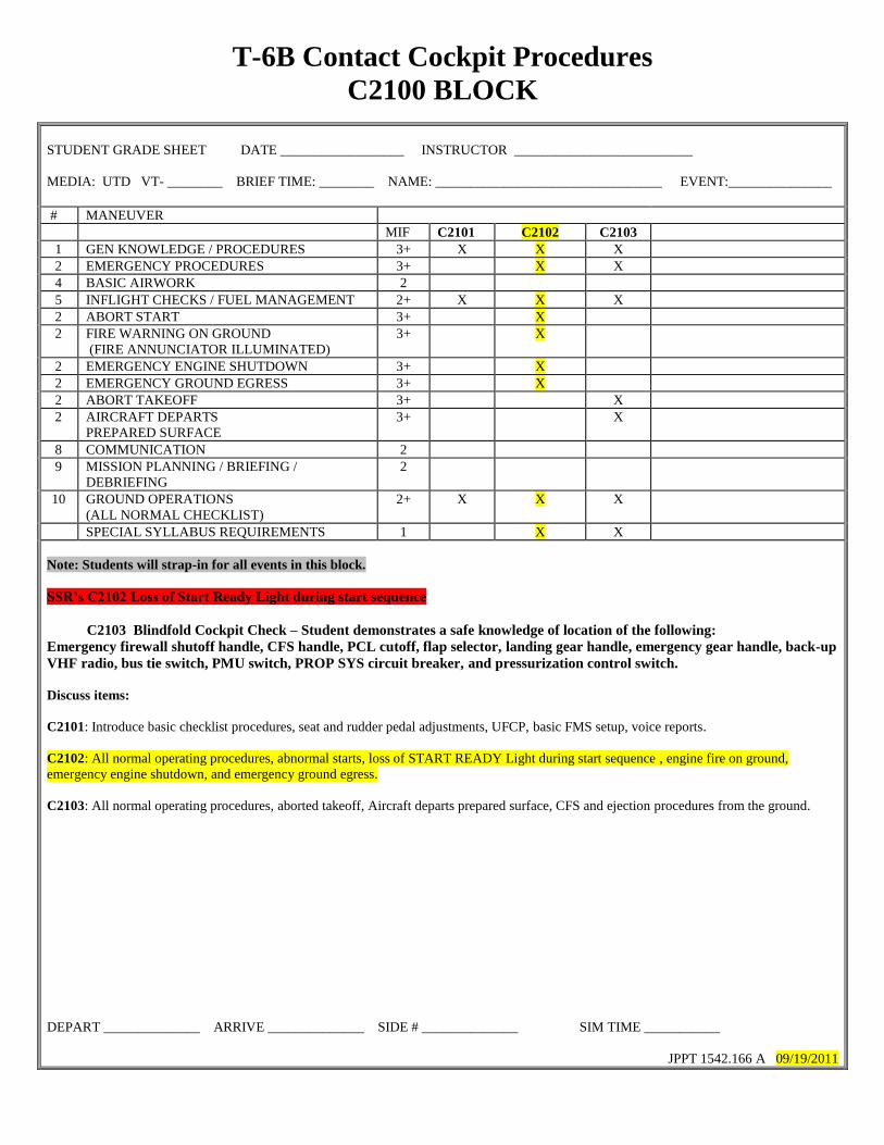
T-6B Contact Cockpit Procedures
C2100 BLOCK
STUDENT GRADE SHEET DATE __________________ INSTRUCTOR __________________________
MEDIA: UTD VT- ________ BRIEF TIME: ________ NAME: _________________________________ EVENT:_______________
# MANEUVER
MIF C2101 C2102 C2103
1 GEN KNOWLEDGE / PROCEDURES 3+ X X X
2 EMERGENCY PROCEDURES 3+ X X
4 BASIC AIRWORK 2
5 INFLIGHT CHECKS / FUEL MANAGEMENT 2+ X X X
2 ABORT START 3+ X
2 FIRE WARNING ON GROUND
(FIRE ANNUNCIATOR ILLUMINATED)
3+ X
2 EMERGENCY ENGINE SHUTDOWN 3+ X
2 EMERGENCY GROUND EGRESS 3+ X
2 ABORT TAKEOFF 3+ X
2 AIRCRAFT DEPARTS
PREPARED SURFACE
3+ X
8 COMMUNICATION 2
9 MISSION PLANNING / BRIEFING /
DEBRIEFING
2
10 GROUND OPERATIONS
(ALL NORMAL CHECKLIST)
2+ X X X
SPECIAL SYLLABUS REQUIREMENTS 1 X X
Note: Students will strap-in for all events in this block.
SSR’s C2102 Loss of Start Ready Light during start sequence
C2103 Blindfold Cockpit Check – Student demonstrates a safe knowledge of location of the following:
Emergency firewall shutoff handle, CFS handle, PCL cutoff, flap selector, landing gear handle, emergency gear handle, back-up
VHF radio, bus tie switch, PMU switch, PROP SYS circuit breaker, and pressurization control switch.
Discuss items:
C2101: Introduce basic checklist procedures, seat and rudder pedal adjustments, UFCP, basic FMS setup, voice reports.
C2102: All normal operating procedures, abnormal starts, loss of START READY Light during start sequence , engine fire on ground,
emergency engine shutdown, and emergency ground egress.
C2103: All normal operating procedures, aborted takeoff, Aircraft departs prepared surface, CFS and ejection procedures from the ground.
DEPART ______________ ARRIVE ______________ SIDE # ______________ SIM TIME ___________
JPPT 1542.166 A 09/19/2011
INBOUND TAXI
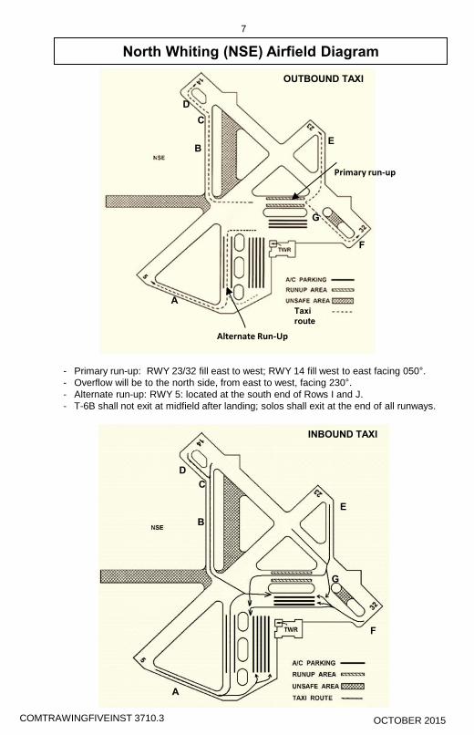
North Whiting (NSE) Airfield Diagram
7
Alternate Run-Up
Primary run-up
A
B
C
D
E
F
G
Taxi
route
OUTBOUND TAXI
INBOUND TAXI
North Whiting (NSE) Airfield Diagram
7
Alternate Run-Up
Primary run-up
A
B
C
D
E
F
G
Taxi
route
OUTBOUND TAXI
- Primary run-up: RWY 23/32 fill east to west; RWY 14 fill west to east facing 050°.
- Overflow will be to the north side, from east to west, facing 230°.
- Alternate run-up: RWY 5: located at the south end of Rows I and J.
- T-6B shall not exit at midfield after landing; solos shall exit at the end of all runways.
COMTRAWINGFIVEINST 3710.3 COMTRAWINGFIVEINST 3710.3
D
C
B
A A
B
C
D
E E
F F
G G
OCTOBER 2015 OCTOBER 2015

3-4 Change 4
AIR FORCE TO 1T-6B-1NAVY NAVAIR A1-T6AAA-NFM-100GROUND EMERGENCIES
ABORT START PROCEDURE
In the AUTO start mode, if a no start is detected or if a hungor hot start is projected, the PMU should terminate the startsequence. However, the engine start should be aborted man-ually in the following situations:
• ITT rate of increase appears likely to exceed 1000 °C(hot start)
• Normal N1 increase is halted (hung start)
• No rise of ITT is evident within 10 seconds after fuelflow indications (no start)
• Red BATT BUS warning message illuminates duringthe start sequence
• PCL is moved or the ST READY green advisory mes-sage extinguishes during the start sequence
NOTENote and report to maintenance the degreeand duration of any overtemperature.
* 1. PCL - OFF; or STARTER switch - AUTO/RESET
NOTEIf start is initiated with PCL in the OFF posi-tion, abort by reselecting AUTO/RESET onthe STARTER switch. If start is initiated withPCL out of the OFF position, but not past theIDLE gate, abort by placing the PCL to OFFor reselecting AUTO/RESET on theSTARTER switch. If the PCL is past theIDLE gate, abort by placing the PCL to OFF.
2. Perform Motoring Run Procedure
• If a start using external power is aborted(PMU or manual abort) due to an actual orsuspected aircraft malfunction, do notattempt subsequent starts.
• Repeated PMU aborted start attempts areindicative of engine malfunction.
NOTE• During ground starts, certain parameters
(weak battery, high OAT, high pre-start ITT,high density altitude, tailwind) may cause thePMU to abort a battery start attempt. Thoughthese parameters are not directly monitoredby the PMU, they cause a rate of rise in N1
and/or ITT that are indicative of an impend-ing hung or hot start.
• If a battery start was aborted (PMU or manualabort), connect external power (if available)and perform Motoring Run Procedure. Sub-sequent starts may be attempted if no enginemalfunctions are evident and no limits havebeen exceeded.
MOTORING RUN PROCEDURE
Perform this procedure after any aborted start (auto or man-ual) during which fuel was introduced. Motor the engine toclear residual fuel and/or lower the ITT.
1. PCL - OFF2. IGNITION switch - NORM3. Propeller area - Clear4. STARTER switch - MANUAL for 20 seconds
STARTER switch is not spring-loaded fromMANUAL to NORM.
NOTEObserve starter duty cycle cool-down period.
5. STARTER switch - NORM
FIRE WARNING ON GROUND
The primary indications of an engine fire are illumination ofthe FIRE annunciators. Other indications of an engine fireare visual smoke or fire, engine indications (high ITT, fluc-tuating or high fuel flow), and notification from exteriorsources such as ground crew, tower, or another aircrew.When evidence of a fire exists during start or other groundoperations, perform the Emergency Engine Shutdown OnThe Ground procedure and Emergency Ground Egress pro-cedure if applicable.
EMERGENCY ENGINE SHUTDOWN ON THE GROUND
In the event of an engine fire, prop strike, or chip light; if theaircraft appears likely to depart the prepared surface; orshould any other serious ground emergency occur, accom-plish the following:* 1. PCL - OFF * 2. FIREWALL SHUTOFF HANDLE - PULL* 3. Emergency ground egress - As required

Change 4 3-5
AIR FORCE TO 1T-6B-1NAVY NAVAIR A1-T6AAA-NFM-100
EMERGENCY GROUND EGRESS
NOTEIn a situation requiring immediate groundegress, the ejection system has the capabilityfor 0/0 ejection.
If emergency egress is required on the ground (Figure 3-1),perform the following steps after the aircraft has come to acomplete stop and the engine has been shut down:* 1. ISS mode selector - SOLO
Failure to ensure that the ISS mode selector isset to SOLO may result in the inadvertentejection of one or both seats.
* 2. Seat safety pin - Install (BOTH)
Failure to insert both ejection seat safety pins(if occupied) before ground egress may resultin inadvertent activation of ejection sequenceand subsequent injury or death when per-forming emergency ground egress.
* 3. PARKING BRAKE - As required* 4. Canopy - Open
IF CANOPY CANNOT BE OPENED OR SITUATIONREQUIRES RIGHT SIDE EGRESS:* 5. CFS handle - Rotate and pull (BOTH)
• If the canopy fracturing system malfunctionsin conjunction with a canopy latch failure inthe locked position, ejection may be the onlyoption remaining to exit the aircraft. Aircrewshall remove the ejection seat safety pin andensure shoulder straps, lap straps, and legrestraint garters are still attached prior to pull-ing ejection handle.
• To prevent injury, ensure oxygen mask is onand visor is down prior to actuating the CFSsystem.
• Each internal CFS handle activates only theCFS charge for the respective transparency.Both internal CFS handles must be activated
in order to fracture both transparencies (ifrequired).
* 6. Upper fittings, lower fittings, and leg restraint garters- Release (BOTH)
Actuate leg restraint line quick-release lever on left side ofseat or use individual quick-release connectors on legrestraint garters.
NOTEOxygen hose, emergency oxygen hose, com-munication leads, and anti-G suit hose willpull free while vacating cockpit and legrestraint lines will pull through leg restraintgarter D rings if released with quick-releaselever.
* 7. BAT, GEN, and AUX BAT switches - OFF* 8. Evacuate aircraft
TAKEOFF EMERGENCIESThere are several factors which affect the pilot’s decision totakeoff or abort. The decision to takeoff or abort should bebased on the following:
• Runway length and condition, terminal weather condi-tions and area traffic.
• If adequate directional control cannot be maintained orany system emergency affecting safety of flight isexperienced prior to Max Abort Speed, the takeoffshould be aborted.
ABORT
If it becomes necessary to abort the takeoff, concentrate onmaintaining aircraft control, specifically directional control,while stopping the aircraft on the remaining runway. Toabort a takeoff, accomplish the following:* 1. PCL - IDLE* 2. BRAKES - AS REQUIRED
Refer to Section II for description of maximum brak-ing.
After a stop which required maximum effortbraking and if overheated brakes are sus-pected, do not taxi into or park in a congestedarea until brakes have had sufficient time tocool. Do not set parking brake.

2-16 Change 4
AIR FORCE TO 1T-6B-1NAVY NAVAIR A1-T6BAA-NFM-100
If IOAT exceeds 121 °C, the PMU will flag the IOAT signal,lose the ability to calculate ITT, and go offline. This condi-tion is indicated by red X’s in the IOAT and ITT counters,removal of the ITT pointer on the EICAS display, and byillumination of the PMU FAIL warning. The PMU will notreset until IOAT drops below 121 °C.
Use the following procedure if IOAT exceeds 80 °C:1. PCL - Verify OFF2. PMU - Reset if necessary
(The PMU has reset if IOAT reads 121 °C or less, theITT counter and pointer are present on the EICAS dis-play, and the EDM FAIL message is not displayed.)
3. PMU switch - OFF
Do not rotate the propeller by hand to reduceIOAT. Rotating the propeller without oilpressure can damage the engine. Slow andlimited hand rotation of the propeller forinspection purposes is acceptable.
4. Propeller area - Clear5. STARTER switch - MANUAL for 20 seconds maxi-
mum
(Observe starter duty cycle cool-down period.)6. STARTER switch - NORM7. Repeat Steps 4-6 if IOAT is greater than 80 °C8. PMU switch - NORM9. Continue with Engine Start
ENGINE START (AUTO)
1. Canopy - Closed and latched (BOTH)
(Lift lock release lever, check master warning and can-opy annunciator illuminate and internal canopy handledoes not independently rotate aft. Release lock releaselever, extinguish master warning, check canopyannunciator extinguished, handle cannot be rotated aft,and green canopy mechanical lock indicators visible.)
• Failure to properly latch the canopy couldlead to canopy opening during flight, leadingto a possible loss of control during flight andinability to eject.
• Failure to close the canopy prior to enginestart may result in injury or damage to the air-craft due to exhaust and propwash.
• To prevent injury or damage to canopy,ensure canopy rail and locking lever are clearprior to closing canopy. Ensure canopy han-dle is in the open position prior to closing thecanopy to prevent damage to the lockingmechanism.
• Ensure minimum adequate canopy/helmetclearance by placing closed fist on top of hel-met when adjusting seat height. Excessiveseat height (helmet above canopy breakers)can result in fatal injury upon ejection.
Avoid applying abrupt and/or excessive forceto the canopy locking handle at all times.Excessive force in any direction may damagethe canopy locking mechanism.
2. Navigation and anti-collision lights - As required
NOTE
Anti-collision strobes may be left off if oper-ation is distracting, such as for ground opera-tions at night.
3. PMU FAIL/PMU STATUS message - Extinguished
(If PMU FAIL or PMU STATUS messages are illumi-nated, set PMU switch to OFF, then NORM.)
With the PMU STATUS caution, the PMUauto abort function may be unavailable. Donot continue Engine Start (AUTO) proce-dures.
4. PCL - Advance to start position (ST READY advi-sory)
Failure to ensure the ST READY lightremains illuminated may result in enginedamage due to loss of the automatic shut-down feature.
5. Propeller area - Clear6. STARTER switch - AUTO/RESET