Embed Size (px)
Citation preview

C11T (Rev.1.1) User Manual
Revision: 12/01/2009 http://cnc4pc.com/TechDocs/C11TR1_1_User_Manual.pdf 1/19
C11T- MULTIFUNCTION CNC BOARD Rev. 1.1
W/Driver Control
User manual Rev. 2
1. Overview
This card is the latest addition to the C11 – Multifunction CNC Board family of breakout
boards. It incorporates a microcontroller that runs programs that monitor the drivers, e-
stop and perform other functions. This card has been designed to provide a flexible
interface and functions to your computer projects, by using the parallel port control
software.
2. Features
• Buffered outputs. Outputs are buffered through the use of high speed and high current buffers allowing the card to output the signals without using the power from
the parallel port. It can take the +3.3 or +5vdc signal from the parallel port and deliver solid +5vdc at 24 milliamps.
• Microcontroller based SCHP.

C11T (Rev.1.1) User Manual
Revision: 12/01/2009 http://cnc4pc.com/TechDocs/C11TR1_1_User_Manual.pdf 2/19
This board comes with a
microcontroller that allows the
implementation of a complex
algorithm for sampling and analyzing
the SCHP signal.
• Built-in Variable Speed Control. It has an optoisolated analog 0-
10VDC output that will convert a step signal into an analog signal that can be used to command a commercial VFD. This analog can be adjusted using on-board potentiometer, so this board can be adjusted to other voltages.
• Monitors E-Stop, Safety Charge Pump, and Drivers (it only monitors (G320/340 drives at this time).
• Enables and disables the drivers.
• Microcontroller Based Monitor System.
• Electromechanical Relay with NO and NC positions “Pin 16”.
Mechanical relays are very flexible because they can be used for AC or DC and come with NO and NC (Normally Open and Normally Closed) positions.
• Built-in 10 amp AC Solid State
Relay “Pin 1”. It is very useful to
use a solid state relay instead of a
mechanical relay for starting motors
or other devices that might produce
arcs at contact. This will increase the
life of the motors and relay. This
relay is also optoisolated from the
rest of the board and has a
replaceable fuse.
• Status LEDs on all inputs and output connections. No more guessing. You can SEE all your signals. Save valuable time and brainpower for CNCing. To avoid remaining current to the main load (driver or other device), all the indicator LEDs are driven by independent buffers of the ones that drive de output.
• Output pins 1, 2, 3, 4, 5, 6, 7, 8, 9, 14, 16, 17.
• Input pins 10, 11, 12, 13, 15.
• Input and output pins with close by ground or +5vdc connections
• The common terminal to pins 2-9 can be ground or +5vdc. Forget about grounding problems. Easily connect your pin by using your close by ground connection. No need to be an electronics expert to ground all your stuff. The board has a dipswitch that allows you to select if the common terminal to pins 2-9 will carry a ground or +5vdc. So if you are connecting encoders or proximity switches, you can select it to ground. If you are connecting Geckodrives or limit switches, you can set It to be +5VDC.
• External Enable Pin (EN). The board has a pin that allows you to enable/disable all the outputs at once. The board requires +5vdc in the EN pin. If it is not present, it will send all the outputs to ground. You

C11T (Rev.1.1) User Manual
Revision: 12/01/2009 http://cnc4pc.com/TechDocs/C11TR1_1_User_Manual.pdf 3/19
can use this to enable or disable the system manually, or you can install an external Safety Charge Pump or other external safety monitoring device.
• Works directly with popular CNC hardware and software. Such as Geckodrive, DeskCNC or Rutex, and parallel port control software, such as mach2, Linux EMC, TurboCNC, CNCPlayer, CNCZeus and others. (Not all tested).
• All TTL 5VDC signals. Interface directly with parallel port interface products and other CNC4PC cards. 5VDC (TTL) cards are very common among automation devices.
• Screw-On connections for all terminals. You only have to screw-on the wires to make all your connections.
• All pins can be used in a concurrent manner. You can use all the input or output pins in a concurrent manner. For example, if you are using output pin #1 to control the Built-in Electromechanical Relay, you can also access that signal from the output pin on the board or from the DB25 connector for output. Each connection will not affect the other current from the other connection.
3. Specifications.
DIGITAL INPUT SPECIFICATIONS
On-state voltage range 2 to 5V DC
Maximum off-state voltaje 0.8V
Maximum operation frequency
500KHz@Pin 15, 10KHz@Others
input pins.
Typical signal delay 100uS
DIGITAL OUTPUT SPECIFICATIONS
Maximum output voltage (5V power supply voltage) + 0.5V
Typical output current 24mA
Maximum off-state voltaje 0.44 V
Maximum operation frequency 4 MHz
Typical signal delay 10 nS
Time of transition to high impedance state 12 nS*
*Time passed since a low in the ENABLE input is detected and the outputs are disabled

C11T (Rev.1.1) User Manual
Revision: 12/01/2009 http://cnc4pc.com/TechDocs/C11TR1_1_User_Manual.pdf 4/19
Requirements:
It requires a 5VDC @ 1.5 Amp. power supply to operate.
WARNING
Check the polarity and voltage of the external power source and connect the 5V
and GND. Overvoltage or reverse-polarity power applied to these terminals can
cause damage to the board, and/or the power source.
WARNING: This card must have the power supplied while it is connected to the PC. If power is removed to the card while it is connected to the PC, noise can be introduced to the output lines. This can create a dangerous situation as relays or other devices that might be connected to this card could get activated.

C11T (Rev.1.1) User Manual
Revision: 12/01/2009 http://cnc4pc.com/TechDocs/C11TR1_1_User_Manual.pdf 5/19
4. Functional Block Diagrams
4.1 Digital outputs simplified block diagram
Fig. 1 Simplified functional block diagram for the digital outputs.
Note: “Internal Enable” = “External Enable Pin” AND (“SCHP” OR “Bypassed SCHP”)
The “Internal Enable” is the result of an AND Operation between the “External Enable
Pin”and the SCHP operation mode selected by the user.
4.2 Inputs simplified block diagram
Fig. 2 Simplified functional block diagram for the inputs.

C11T (Rev.1.1) User Manual
Revision: 12/01/2009 http://cnc4pc.com/TechDocs/C11TR1_1_User_Manual.pdf 6/19
5. Special Functions
5.1 Safety Charge Pump “SCHP”. (Pin 17) This board takes advantage of Mach ability to send a specific frequency through
one of the pins of the parallel port when the program is in control of the system.
CNC machinery can be very dangerous, and you could have a risk of the machine
doing something different that what you intend the machine to do if the program
loses control of your system. Mach be can be programmed in a way, so when it is
“in control”, it delivers a 12.5 KHz signal through one of the pins. This card lets you
use this signal to work as an On/Off switch for your system, enabling a powerful
safety system for your equipment. If you ever had windows crash on you, then this
card is for you. The port can also do weird things while the system is coming up, or
down.
For Configuring the Charge Pump in Mach X: Use the dialog Config / Ports and pins / Output Signals. Enable the Charge Pump output and configures it as is shown in the Fig. 8 Next, press the apply button.
Fig. 3. Charge Pump configuration

C11T (Rev.1.1) User Manual
Revision: 12/01/2009 http://cnc4pc.com/TechDocs/C11TR1_1_User_Manual.pdf 7/19
Selecting the SCHP operation mode.
DIPSWITCH 2 located in the center of the board turns on and off the safety charge pump feature.
SWITCH 2 ON: SCHP ON
SWITCH 2 OFF: SCHP OFF
5.2 Variable Speed Control. (pin 14)
This function lets you control your spindle with step and direction signals, as if it was an axis motor. It converts the step signal into an analog (0-10VDC) . A Variable Frequency Drive or Inverter works by modifying the frequency for AC motors. You can control most of these devices with an external analog signal (0-10VDC). That is, if there is 5VDC coming into through the control signal, the motor will run at 50% of full speed, if there was 10VDC, the motor will run at 100% of full speed. If there is no signal coming out, then the motor will stop. This function can also be used on many DC motor controllers by replacing the potentiometer that controls the speed.
Requirements:
It requires a +12VDC@ 50mA power supply to operate.
WARNING: To keep the output signals optoisolated, these must not
have common ground or connections to current with other circuits you
are using.
You will require a voltmeter to fine tune your system.

C11T (Rev.1.1) User Manual
Revision: 12/01/2009 http://cnc4pc.com/TechDocs/C11TR1_1_User_Manual.pdf 8/19
Wiring:
Before connecting anything, please be sure to read your VFD’s manual and
make sure you understand all the safety issues.
Please check the wiring guide and wiring samples here:
http://cnc4pc.com/Tech_Docs/C6R5_WG.pdf and
http://cnc4pc.com/Tech_Docs/C6R5_WS.pdf
Configuring the Control Software:
It is strongly recommend you read your control software’s manual. You need to
configure your control software to control the spindle as if it was an angular axis.
This card requires a 25 KHz input signal in the pin 14 to deliver 10VDC. So you
have to set the speed of the motor (spindle) at maximum. For acceleration values
adjust them to where you feel comfortable. Keep in mind the acceleration of the
motor must also be set in your VFD.
For configuring Mach follow these steps:
1. Go to Config / Ports&Pins / Motor Outputs. Enable the spindle and select the port and pins you wired for step and direction.
Fig. 4. Ports&Pins configuration screenshot
2. Go to Config / Ports&Pins / Spindle Setup. In the motor control box, check Use Spindle Motor Output and Step /Dir Motor. Under Pulley Ratios set the pulley ratios of the machine.

C11T (Rev.1.1) User Manual
Revision: 12/01/2009 http://cnc4pc.com/TechDocs/C11TR1_1_User_Manual.pdf 9/19
Fig. 5. Spindle Setup screenshot.
3. Go to Config / Motor Tuning / Spindle. On Steps per unit put 1,000, set velocity to
maximum. For Acceleration, choose the acceleration that you feel comfortable with. Start slow, increase acceleration as you test your system. Under Step Pulse length, use a number from 3 to 5, but start with 3. This number is directly proportional to the final voltage you will get in the analog output. Use this number and the fine tuning pot to adjust the voltage you want to get at max speed.
Fig. 6. Motor Tuning and Setup screenshot.
C11T (Rev.1.1) User Manual
Revision: 12/01/2009 http://cnc4pc.com/TechDocs/C11TR1_1_User_Manual.pdf 10/19
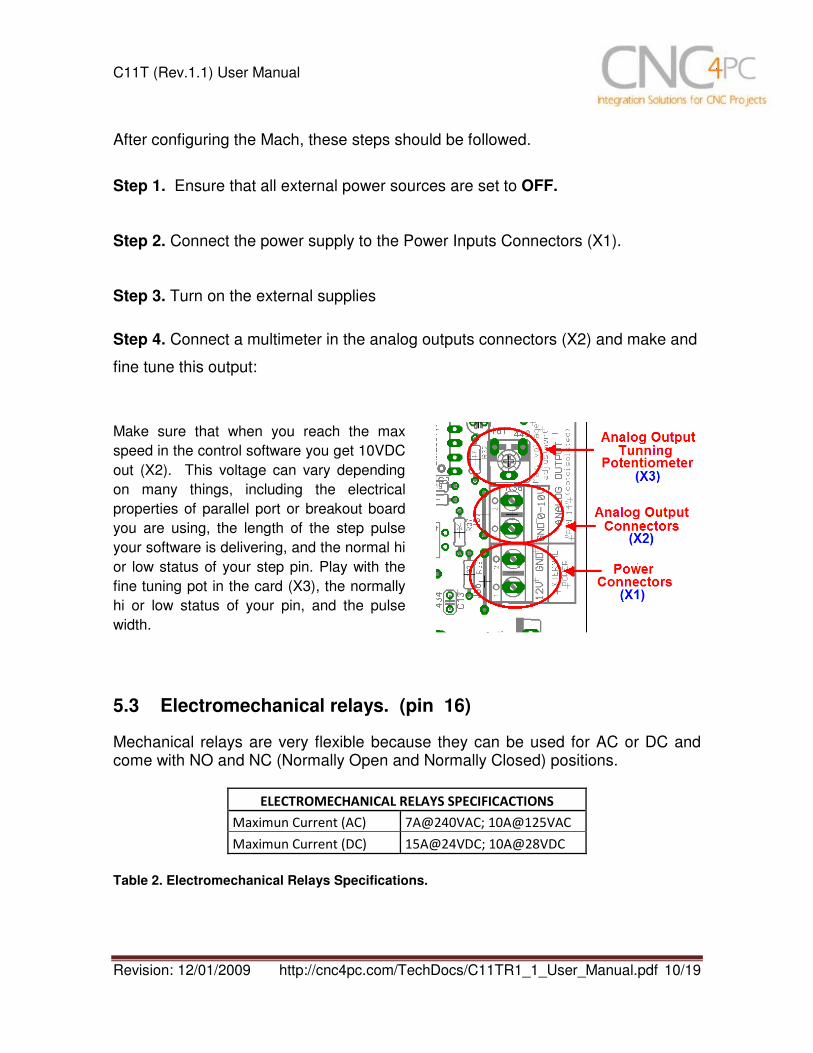
After configuring the Mach, these steps should be followed.
Step 1. Ensure that all external power sources are set to OFF.
Step 2. Connect the power supply to the Power Inputs Connectors (X1).
Step 3. Turn on the external supplies
Step 4. Connect a multimeter in the analog outputs connectors (X2) and make and
fine tune this output:
Make sure that when you reach the max
speed in the control software you get 10VDC
out (X2). This voltage can vary depending
on many things, including the electrical
properties of parallel port or breakout board
you are using, the length of the step pulse
your software is delivering, and the normal hi
or low status of your step pin. Play with the
fine tuning pot in the card (X3), the normally
hi or low status of your pin, and the pulse
width.
5.3 Electromechanical relays. (pin 16)
Mechanical relays are very flexible because they can be used for AC or DC and come with NO and NC (Normally Open and Normally Closed) positions.
ELECTROMECHANICAL RELAYS SPECIFICACTIONS
Maximun Current (AC) 7A@240VAC; 10A@125VAC
Maximun Current (DC) 15A@24VDC; 10A@28VDC
Table 2. Electromechanical Relays Specifications.

C11T (Rev.1.1) User Manual
Revision: 12/01/2009 http://cnc4pc.com/TechDocs/C11TR1_1_User_Manual.pdf 11/19
5.4 Using the COM configuration pin in the DIPSWITCH.
There are COM terminals found next to step and direction terminals (Pin 2-9). Some drivers expect a ground, and others expect +5vdc. There is a jumper (X7) that allows you to select +5VDC or GND for the COM pins. When is selected an specific Gecko driver, automatically the COM terminal are set as it is required by the Driver.
6. Microcontroller based driver monitoring system. This board incorporates a microcontroller that runs programs that monitor the drivers, e-stop and perform other functions.
Functions:
• Enables and disables the drivers.
• Monitors E-Stop.
• Monitors Safety Charge Pump,
• Monitors the Drivers errors pins. (it only monitors (G320/340 drives at this time).
• Indicates the fault source.
• Indicates the system Status.
6.1 Configuration DIPSWITCH
The DIPSWITCH allow to activate or deactivate the SCHP detection function, and
to select the driver to be monitored.

C11T (Rev. 1.1) User Manual
Revision: 12/01/2009 http://cnc4pc.com/TechDocs/C11TR1_1_User_Manual.pdf 12/19
SWITCH 1: Reserved for future functions SWITCH 2 ON: Activate the SCHP detection function SWITCH 2 OFF: Deactivate the SCHP detection function SWITCH 3 and 4: Selects the driver you will use according to the below table.
Note: When is selected an specific driver automatically the COM terminals are set as it is required by the driver.
6.2 Program description
Fig. 7. Wiring sample.
The image above shows an example of how to connect a GECKO DRIVE to a C11T breakout board. In order to use the driver monitoring function it is necessary to connect the gecko ERR/RES terminal to the C11T EN terminal.

C11T (Rev. 1.1) User Manual
Revision: 12/01/2009 http://cnc4pc.com/TechDocs/C11TR1_1_User_Manual.pdf 13/19
Normally when the GECKO DRIVE is first powered up, it will be necessary to push the momentary switch to START for 5 seconds. This will clear the power-on reset condition and extinguish the FAULT LED. The motor will then be enabled and the drive will begin to operate. This START function is automatically done by the built in microcontroller based circuit when the SCHP is validated, when the board is power up when the SCHP function is disabled by the user. The standby LED will light to indicate that the system is ready but disabled. If the system faults it will lite again to indicate that the system is ready to enabled again. There are 3 possible error sources, a driver fault, an E-STOP error and a SCHP error. If at any time after that a condition occurs that causes the GECKO SERVO DRIVE to “fault out”, such as not being able to complete a step command, the ERR/RES terminal will be activated, signaling the microcontroller an error has occurred. In this case the Standby LED indicator and the respective driver error LED indicator will light up in order to indicate to the user that an error has occurred in an specific driver.
If the E-STOP button is pressed the Standby LED indicator and the E-STOP error LED indicator will light up. If the SCHP detection function is activated, and the system is ready (STANDBY LED OFF), and an error has occurred with the SCHP signal, the Standby LED indicator and the SCHP error LED indicator will light up.

C11T (Rev. 1.1) User Manual
Revision: 12/01/2009 http://cnc4pc.com/TechDocs/C11TR1_1_User_Manual.pdf 14/19
7. Wiring diagrams Different kind of sensors and switches can be connected to inputs board, but this
board support only TTL signal, so if you need to connect devices that generates
12V or 24V signal in some cases is necessary add external resistors.
Note. All inputs have the same configuration. The below wiring diagrams are an example,
any input can be used for the connections.
Fig. 8 Wiring diagram to connect switches.
Fig. 9 Wiring diagram to connect NPN open collector proximity sensors.
For a 24V or 12V sensor, the recommended value for the external resistor R1 is
4.7K Ohm.

C11T (Rev. 1.1) User Manual
Revision: 12/01/2009 http://cnc4pc.com/TechDocs/C11TR1_1_User_Manual.pdf 15/19
Fig. 10 Wiring diagram to connect in parallel NPN open collector proximity sensors.
Fig. 11 Wiring diagram to connect NPN proximity sensors with internal pull up resistor.

C11T (Rev. 1.1) User Manual
Revision: 12/01/2009 http://cnc4pc.com/TechDocs/C11TR1_1_User_Manual.pdf 16/19
Fig. 12 Wiring diagram to connect PNP open collector proximity sensors
Connecting PNP open collector proximity sensor with the C11T Rev. 1.1
Board R Value (12V) R Value (24V)
C11T Rev. 1.1 470Ω 1KΩ
Table 1. R value to Connect PNP open collector proximity sensor with the C11T.
Fig. 13 Wiring diagram to do an “Auto Tool Zero”

C11T (Rev. 1.1) User Manual
Revision: 12/01/2009 http://cnc4pc.com/TechDocs/C11TR1_1_User_Manual.pdf 17/19
8. Troubleshooting. SYMPTOM 1: THE BOARD DOES NOT REACT TO THE SIGNAL.
POSSIBLE CAUSE POSSIBLE SOLUTIONS
- Pin conflict or mach3 configuration.
It is possible that the port address
used for the pin is not right, or that
there is a pin conflict with the. That is
that you are using that same pin twice.
(it could be assigned to a different
function).
- Go to the device manager in windows,
and check the memory address used for
the parallel port you are using. Usually it
will be 378 for LPT1. Check also that
the port does not have a conflict. Then
in mach3, go to Ports & Pins / Port Setup
and Axis Selection. Check the memory
address is correct.
- Check that the pin you are using is not
been used anywhere else in your setup.
Got to motor output and output signals,
and check all the entries.
- The board does not like the
waveform it is getting. Some
breakout boards could invert the
signals or modify the pulse width.
Changing the active low status of the
pin used also inverts the waveform.
- Play with the active low status of the pin
used for the frequency.
- The signal or frequencies are not
getting to the board. It could be the
cable or that you are passing the
signal through the same breakout
board that you are enabling/disabling,
so the outputs could be disabled, so
they will not get to the breakout board.
- Try a different cable.
- Test the pins in the cable (before they
reach the breakout board) with a
multimeter.
- Problems with Mach3 Pulse
Generation. Mach3 could have
installation problems (you did not
restart immediately after installation),
or there could be something creating a
conflict. Some dongle devices might
cause this, other software, like
QuickTime or drivers for touch screen.
- Test this in a different PC.
- Follow Art’s suggestions for optimizing
up WinXP:
http://www.machsupport.com/downloads/
XP_Optimization.txt.

C11T (Rev. 1.1) User Manual
Revision: 12/01/2009 http://cnc4pc.com/TechDocs/C11TR1_1_User_Manual.pdf 18/19
SYMPTOM 2: THE OUTPUTS DO NOT GET ENABLED / NO SIGNALS ARE
COMING OUT.
POSSIBLE CAUSE POSSIBLE SOLUTIONS
- The EN terminal (Enable Outputs) is
not enabled. The board requires to be
externally enabled.
- The parallel cable is not well
connected to the PC parallel port.
- Make sure you are providing +5vdc to
the EN terminal. This +5vdc can be
taken from the terminal next to it.
- Check if the parallel port is well
connected to the PC.
SYMPTOM 3: THERE IS NOISE IN THE SYSTEM, OR THE MOTORS DO NOT
MOVE SMOOTHLY.
POSSIBLE CAUSE POSSIBLE SOLUTIONS
- The board could be underpowered. - Make sure you are using a +5vdc
1500mA power supply.
- There could be a short that could be
draining the power to the board.
- Check that there are no hot spots in the
board or it’s connections.
- Measure the board’s power
consumption, it should be less than
400mA (depending on the features
used).
- Blown chips could create an internal
short and end up drawing power that can
affect how other chips work.
- There could be an external noise
source that could be introducing
noise into the system.
- Try using shielded cables. - Try to isolate VFDs or AC servos, etc. - Try using 103. 0.1mF caps between the
I/O terminal and a ground of the board.
SYMPTOM 4: A I/O PIN MIGHT NOT BE WORKING.
POSSIBLE CAUSE POSSIBLE SOLUTIONS
- A chip may have gone bad. These
buffers could act as fuses for the
signals, and they can go bad because
of noise spikes or even strong static.
- These chips are inexpensive and readily
available. You can order them here:
http://www.cnc4pc.com/Store/osc/index.ph
p?cPath=38_43.

C11T (Rev. 1.1) User Manual
Revision: 12/01/2009 http://cnc4pc.com/TechDocs/C11TR1_1_User_Manual.pdf 19/19
- Carefully moving chips around and
checking if the problem moves around
could be a way of figuring out if this is
the case.
- There could be a problem with the
parallel cable or parallel port.
- Test this with a different PC or parallel
port.
SYMPTOM 5: THE ANALOG OUTPUT DOES NOT REACH THE 10VDC.
POSSIBLE CAUSE POSSIBLE SOLUTIONS
- Insufficient pulse width. It is possible
that the signal pulse width is not
enough to activate the optocouplers.
- In Mach X, go to Config / Motor Tuning /
Spindle. Under Step Pulse length
increase this value, use a number from 3
to 5, but start with 3.
- The signal is set active low or the
breakout board could be inverting
the signals.
- In Mach X, go to Config / Ports&Pins /
Motor Outputs. Change the active low
status of the pin used for step.

C11T (Rev. 1.1) User Manual
Revision: 12/01/2009 http://cnc4pc.com/TechDocs/C11TR1_1_User_Manual.pdf 20/19
9. Dimensions.
All dimensions are in Millimeters.
Disclaimer: Use caution. CNC machines could be dangerous machines. DUNCAN USA, LLC or Arturo Duncan are not liable for any accidents resulting from the improper use of these devices. The C11T is not fail-safe device, and it should not be used in life support systems or in other devices where its failure or possible erratic operation could cause property damage, bodily injury or loss of life.