Embed Size (px)
Citation preview

C101 Report
District I 1625 N. French Dr., tfobbs, NM 88240 Phone:(575) 393-616 l|F| District II 811 S. First St.. Artesia~NM 88210 Phone:(575) 748-1283 Fax:(575)748-9720 District HI 1000 Rio Brazos Rd., Aztec, NM 87410 Phone:(505) 334-6178 Fax:(505) 334-6170 District IV 1220 S. St Francis Dr.. Santa Fe, NM 87505 Phone:(505) 476-3470 Fax:(505) 476-3462
RECEIVED APR 2 9 2013
SSAI
Page 1 of 1
State of New Mexico
- ? ^ D ° A q ^ ^ 1 Minerals and Natural Resources Oil Conservation Division
1220 S. St Francis Dr. Santa Fe, NM 87505
FoimC-101 August 1. 2011
Permit 166153
APPLICATION FOR PERMIT TO DRILL, RE-ENTER, DEEPEN, PLUGBACK, OR ADD A ZONE 1. Operator Name and Address
OXY USA INC
PO Box 4294
Houston, TX 77210
2. OGRID Number
16696
1. Operator Name and Address
OXY USA INC
PO Box 4294
Houston, TX 77210 3. API Number .
4. Property Code 5. Property Name t
CEDAR CANYON 16 SWD Q fa
6. Well No.
003
7. Surface Location UL - Lot Section Township Range LotIdn Feet From N/S Line Feet From E/W Line County
D 16 24S 29E D 725 N 660 W EDDY
8. Proposed Bottom Hole Location UL - Lot Section Township Range Lot Idn Feet From N/S Une Feet From EAV Line County
D 16 24S 29E D 725 N 660 W Eddy
9. Pool Information |SWD;DELAWARE 96-100i
Additional Well Information 11. Work Type
New Well
12. Well Type
OIL
13. Cable/Rotary 14. Lease Type
Private
15. Ground Level Elevation
2927
16. Multiple
N
17. Proposed Depth
4400
18. Formation
Delaware
19. Contractor 20. Spud Date
7/1/2013
Depth to Ground water Distance from nearest fresh water well Distance to nearest surface water
21. Proposed Casing and Cement Program Type Hole Size Casing Type Casing Weight/ft Setting Depth Sacks of Cement Estimated TOC
Surf 12.25 9.625 36 310 210 0
Prod 8.75 7 26 4400 1230 0
Casing/Cement Program: Additional Comments
Additional information wil l be sent with the C-144 CLEZ & H2S Plan.
22. Proposed Blowout Prevention Program Type Working Pressure Test Pressure Manufacturer
DoubleRam 5000 5000
Annular 3000 3000
23.1 hereby certify that the information given above is true and complete to the best of my knowledge and belief. I further certify I have complied with 19.15.14.9 (A) NMAC 53 and/or 19.15.14.9 (B) NMAC 63; if applicable.
Signature:
OIL CONSERVATION DIVISION 23.1 hereby certify that the information given above is true and complete to the best of my knowledge and belief. I further certify I have complied with 19.15.14.9 (A) NMAC 53 and/or 19.15.14.9 (B) NMAC 63; if applicable.
Signature:
Approved By: / J /~i 1
Printed Name: Electronically filed by KAREN M S1NARD Tide: *fr^0L-OA Msr / / Title: Approved Date:jj l u i l / j ^ \% \ Expiration Date: £ / ( J l b &
Email Address: [email protected]
Date: 4/25/2013 | Phone: 713-366-5485
https://wwwapps.emnrd.state.nm.us/OCD/OCDPermitting/Report/C101/C101Report.aspx?... 4/25/2013

DISTRICT I 1625 N. French Dr.. Hobbs, NM 88240 Phone: (575) 393-6161 Fax: (575) 393-0720 DISTRICT II 811 S. Kirst Si.. Artesia, NM 88210 Phone: (575)748-1283 Fax; (575) 748-9720 DISTRICT 111 1000 Rio Brazos Road, Aztec. NM 87410 Phone: (505)334-6178 Fax: (505) 334-6170 DISTRICT IV 1220 S. SL Francis Dr., Santa Fc, NM 87S05 Phone: (505) 476-3460 Fax; (505) 476-3462
State of New Mexico Energy, Minerals & Natural Resources Department
OIL CONSERVATION DIVISION 1220 South St. Francis Dr.
Santa Fe, New Mexico 87505
WELL LOCATION AND ACREAGE DEDICATION PLAT
Form C-102
Revised August 1.2011
Submit one copy lo appropriate
Dislrici Office
• AMENDED REPORT
API Number , __ Pool Code _
Property Code ' ' " ̂ Property Name
, CEDAR CANYON 16 ScoD Well Number
3 OGRID No. 1 Operator Name
OXY U.S.A. INC. Blevarion
2927'
Surface Location
UL or lot No.
D Section
16 Township
24-S Range
29-E Lol Idn Feet from the
725 North/South line
NORTH Feet from the
660 EastAVesl line
WEST
County
EDDY
Bottom Hole Location If Different From Surface
UL or lot No. Section Township Range Lot Idn Feet from the North/South line l-'eetfrom the East/West line County
Dedicated Acres
o Joint or Infill Consolidation Code ; Order No.
NO ALLOWABLE WILL BE ASSIGNED TO THIS COMPLETION UNTIL ALL INTERESTS HAVE BEEN CONSOLIDATED OR A NON-STANDARD UNIT HAS BEEN APPROVED BY THE DIVISION
GEODETIC COORDINATES NAD 27 NME
SURFACE LOCATION y= 444915.5 N X=604501.4 E
LAT =32.222738- N L0NG.= 103,995408' W
+
OPERATOR CERTIFICATION
/ hereby certify that the information herein is true and complete to the best of my knowledge and beiief, and thai this organization either owns a working interest or unleased mineral interest in the land including the proposed bottomhole location or has a right to drill this well at this location pursuant to a contract with an owner of such mineral or working interest, or to a voluntary pooling agreement or a compulsory pooling order heretofore entered by the division.
Signature Date
Printed Name
E-mail Address
SURVEYOR CERTIFICATION
/ hereby certify that the well location shown on this plat was plotted from field notes of actual surveys made by mc or under my supervision, and that Uic same is true and correct to the best of my belief.
MARCH 15,2013
Date of Survey
Signature & Seal c^Jjratos^onal Surveyor:
% 3D : { 12641 a : | BKL
Gary p: tflson
12641 3239
e-W.O.: 13:11.0263

Operator Name/Number: OXY USA Inc. 16696 Lease Name/Number: Cedar Canyon 16 SWD #3 39045 Pool Name/Number: Cedar Canyon Delaware 11540 Surface Location: 725 FNL 660 FWL D Sec 16 T24S R29E
C-102 Plats: 3/15/13 3/27/13 4/18/13 Elevation: 2927' GL
Proposed TD: 4400' SL - Lat: 32.2222738
Casing Program:
TVD Long: 103.995408 X=604501.4 Y=4444915.5 NAD -1927
Hole Size
Interval OD Csq Weiqht Collar Grade Condition Collapse Desiqn Factor
Burst Desiqn Factor
Tension Desiqn Factor
12-1/4" 0-310' 9-5/8" 36 ST&C J-55 New 14.92 2.38 3.54 Hole filled with 8.4# Mud 2020# 3520#
8-3/4" 0-4400' 7" 26 LT&C L-80 New 2.46 4.12 3.38 Hole filled with 9.6# Mud 5410# 7240#
Collapse and burst loads calculatec using Stress Check with anticipated loads
Cement Program: a. 9-5/8" Surface Circulate cement to surface w/ 210sx PP cmt w / 1 % CaCI2, 14.8ppg 1.35 yield
1346# 24hr CS 165% Excess
c 7" Production Circulate cement w/ 850sx HES light PP cmt w/ .5% salt + .35% HR-800, 12.9ppg 1.85 yield 734# 24hr CS, 125% Excess followed by 380sx PP cmt w/ .5& Halad R-344 + .2% WellLife 734 + 5#/sx Microbond + .3% Econolite + .3% CFR-3, 14.2ppg 1.55 yield 1914# 24hr CS 125% Excess
Description of Cement Additives: Calcium Chloride, Salt (Accelerator); WellLife 734 (Cement Enhancer); D-Air 6000 (Defoamer); CFR-3 (Dispersant); Microbond (Expander); Kol Seal, Poly-E-Flake (Lost Circulation Additive); Halad R-344 (Low Fluid Loss Control); HR-601, HR-800 (Retarder)
The above cement volumes could be revised pending the caliper measurement.
Proposed Mud Circulation System: Depth Mud Wt. Vise Fluid Type System
pm sec Loss 0 - 310' 8.4-8.8 27-38 NC Fresh Water/Spud Mud 310' - TD 9.6-10.0 28-40 NC Cut Brine/Salt Gel-Starch Pump high viscosity sweeps as needed for hole cleaning. The mud system will be monitored visually/manually as well as with an electronic PVT. The necessary mud products for additional weight and fluid loss control will be on location at all times.
BOP Program: Surface None
Intermediate/Production 11" 5M two ram stack w/ 3M annular preventer, 5M Choke Manifold
Estimated Tops of Geological Markers & Depths of Anticipated Fresh Water, Oil or Gas: Geoloaical Marker Depth Type
a. Rustler 285' Formation b. Top Salt 330' Formation c. Bottom Salt 2690' Formation d. Base Anhydrite 2875' Formation e. Delaware-Bell Canyon 2968' Oil/Gas f. Delaware-Brushy Canyon 3720' Oil/Gas
Fresh water may be present above the Rustler formation. Surface casing will be set below the top of the Rustler, which will cover potential fresh water sources.

1'-3 3 / 4 " .
TD MANIFOLD
CHOKE-
- 1 - 5 1 /4" FROM STANP1PE MANIFOLD
s ~ KILL
PROPER TORQUE FOR BOLTS COMPONENT FLANGE SIZE
& RATING BOLT SIZE TORQUE (FT/LBS) COMPONENT FLANGE SIZE & RATING BOLT SIZE
CF=0.07 CF=0.13
SPOOLS,
ANNULAR & RAMS
U \ 5 M 1 7 / 8 * OIA. 1890 3330
BLOCKS 3 l /8x5M 1 1/8" D1A 401 686
CHOKE VALVES 3 1/8x5M 1 1 /8* OIA. 401 686
KILL VALVES 2 1 / 1 6 X 5 M 7 / 8 * DIA. 1B8 319
BILL OF MATERIAL ITDJ ffl
DUAfJ DESCRIPTION PART MMBEh WEIGHT
11-5M BOP ASSEMBLY
I ANNULAR. 11x3M BOLTED TYPE 6005
2 90 P DOUBLE RAW 7600
RAM ELEMENTS 444
3 HAMMER UNION. 2-1502f XXH (BW) 5
4 FLANGE, WN Z 1/I6-5M API 42
5 VALVE, GATE FLS-HCJ? J I/B-5W JS6
5 Wi.VE. GATE 2 1/1S-5H 350
7 9ff STUOOED SLOCK, j 1/8-5U X 2 240
a 90' STUDDED BLOCK, 3 1/B-5M X 3 1/B-5M 250
9 VALVE. GATE 3 1/8-5M 720
10 BELL NIPPLE BOP LIFTING SECTION MK. F4M-H-318.01A 780
11 BELL NIPPLE EXTENSION UK. F4U-H-319.01A 396
12 ! !"-5M x 1!"-5M x J ' -3 ' LONS SPACER 600
SPOOL- WORKING PRESSURE 5000 PSI
HARDWARE ITEM fKJ,
QUAN. DESCRIPTION PART WUMBER WEIGHT
RINGS AND BOLTS 400

BILL OF MATERIAL HfcJA
OUAN DESCRIPTION PART NUMBER WT.
A i 2 LOW PRESSURE SPOOL #1 MK.F4U-h-570.01F 239
A 2 POP-OFF/BLEED SPOOL #1 UK.F4M-rl-570.Q1A 157
A 3 POP-OFF/BLEEO SPOOL #2 tK.F4M-H-570.01B 140
A 4 DELETED
A 5 LOW PRESSURE SUCTION SPOOL #1 UK.F4U-H-570.01D 199
A 6 LOW PRESSURE SUCTION SPOOL §2 MK.F4U-H-570.D1H 101
A 7 HOSE-HIGH PRESSURE UK.F4M-H-570.01G 276
A 8 OVERFLOW RETURN SPOOL UK.F4U-K-S63.0M 678
A 9 MUD PUMP/SHAKER SKID SPOOL UK.F4U-H-570.01E 181
10 22FT TS 1 1/2x1 1/2*3/16 (A500) 150
A 11 POP-OFF PIPE HANG"ER SUPPORT UK.F4U-H-570.0lC 30
12 L3x3x1/4 (1'-6" LG) (A36) 7
13 13x3x1/4 ( I ' -S" LG) (A36) 7
14 PLATE, 1/4" THK. 4x2'-3 1/4" (A36) 8
15 L3x3xl/4 (4-11 3/4" LG) (A36) 25
A 16 SHAKER FLOWLINE UK.F4U-K-562.02A 230
A 17 SHAKER FLOWLINE umw-H-56z.oze 281
A IB HOSE UK.F4H-H-5&3.03E
A 19 SPOOL #1 HK.F4M-H-56402A 182
A 20 HIGH PRESSURE HOSE, 3" l.D. x 2 9 - 0 " LG. PHOENIX BEATIY
WITH 3 1/8" - 5M FLANGED ENDS
A 21 SHAKER FLOWLINE MK.F4M-H-562.02C 73
A 22 SHAKER SPOOL UK.F4U-H-562.03B 177
RIGS 345 - 347 ONLY BILL OF MATERIAL
ITEM
NO OUAN. DESCRIPTION1 PART NUMBER WT.
A 23 SHAKER FLOWLINE MK.F4M-H-569-04A 656
A 24 SHAKER FLOWLINE UK.F4U-H-559-04B 118
A 25 SHAKER FLOWLINE UK.F4H-H-569 -04C 67
A 26 SHAKER FLOWLINE HOSE MK.F4W-H-5&9-040 77
A 27 FABRI - 10" AIR ACTUATED KNIFE GATE VALVE SE
A 28 FABRI - 6" AIR ACTUATED KNIFE GATE VALVE 52
A HARDWARE
A A 24 7/8"-9UNC-2A HEAVY HEX HO. CAP SCREW X Z 1/B" LG. 18
A 8 32 3/4"-1DUNC-2A HEAVY HEX HD. CAP SCREW X 1 5/8" LG. 12
PARTIAL PLAN VIEW
PROPRIETARY THIS DRAWING AND THE IDEAS AND INFORMATION INCLUDED IN THIS DRAWING ARE PROPRIETARY AND ARE NOT TO EE REPRODUCED, DISTRIBUTED OR DISCLOSED IN ANY MANNER. WITHOUT THE PRIOR. WRITTEN CONSENT OF A DULY AUTHORIZED OFFICES OF HELMERICH Sc PAYNE INT'L DRILLING CO.
I ENGINEERING APPROVAL DATE
| A A 10/23/OB CC/UWL
A 09/04/OS DRJ
A 0B/D5/oa ADDED SHT 2 tc BOH DRJ
A 07/17/08 ADDED XX-HVY PIPING TO POP-OFF DRJ
REV DATE DESCRIPTION BY
1HELMERICH & PAYNE INTERNATIONAL DRILLING CO.
MUD SYSTEM INTERCONNECT PIPING ASSEMBLY
'• OXY PERMIAN F4M
DRAWN: QjOHNSON D A T E 0 7 / 0 8 / 0 8
SCALE-3/16"=1'-0" SHECT:
OWG. NO.: I REV:
F4M-H-568 D

5M CHOKE MANIFOLD CONFIGURATION
To Mud/Gas Separator To Mud/Gas Separator and/or Pit and/or Pit

5M REMOTE
KILL LINE SCHEMATIC
m L
To Choke Manifold
3 r =3-
11 iS.
From Mud Pumps

^ BILL OF MATERIAL ITEM | QTY. | DESCRIPTION [ LENGTH | WEIGHT
1. ALL STRUCTURAL MATERIAL SHALL BE ASTM - A36. 2 . ALL PIPE SCH. 4 0 MATERIAL SA 10B Gr. B 3. ALL FLANGES SHALL BE SORT. I S O / * MATERIAL SA 105. * . ALL FITTINGS SCH. +0 MATERIAL SHALL BE SA 2 3 * Gr. WPB. 5. TANK FABRICATION SHALL BE IN ACCORDANCE WITH A P t - 6 5 0 .
The designs, In fo rmat ion and d isc losure* on th is dron ing or copies ara
HTU :
CLOSED LOOP SYSTEM BASIC LAYOUT
OXY - H&P - FLEX 4 M Scomi 1. ALL STRUCTURAL MATERIAL SHALL BE ASTM - A36. 2 . ALL PIPE SCH. 4 0 MATERIAL SA 10B Gr. B 3. ALL FLANGES SHALL BE SORT. I S O / * MATERIAL SA 105. * . ALL FITTINGS SCH. +0 MATERIAL SHALL BE SA 2 3 * Gr. WPB. 5. TANK FABRICATION SHALL BE IN ACCORDANCE WITH A P t - 6 5 0 .
The designs, In fo rmat ion and d isc losure* on th is dron ing or copies ara
HTU :
CLOSED LOOP SYSTEM BASIC LAYOUT
OXY - H&P - FLEX 4 M Scomi the exclusrvo conf ident ia l proper ty o f Scomi Internat ional l i m i t e d and ara no t to be reproduced or disclosed to o thers by any rnecns. In any f o r m a t or t ransmi t ted , or t rans la ted Into a mach ine language or used f o r manufac tu re o r other purpose without the wr f tum permiss ion of Scoml Internat ional l i m i t e d , In receipt of such permiss ion, solely and dlrscUy f o r t he purposes consented . This drawing and any copies shed
OMSK Err OATE
P D L 3 / 3 0 / 0 9
w i m c i OKIE
CHECKED BY QUE
S C K £ | M M O p s e
5 2 1 H. S m E n o r h m P o r k x « j East . S a l t s 300, Ho iu tzm. Tax i s 77080
PR01TC ( 2 S l ) - E C O - « 0 i e . N X ( Z f l l ) - 2 8 0 - 8 9 0 8 JOB NO. J OWJTHO NO. 1 REV.
1 e n A o r\0~7 1

W iV im©-{Closed Loop System)
no ft
160 f t

Permian Drilling Hydrogen Sulfide Drilling Operations Plan
New Mexico
Scope
This contingency plan establishes guidelines for the public, all company employees, and contract employees who's work activities may involve exposure to hydrogen sulfide (H2S) gas. While drilling this well, it is possible to encounter H2S bearing formations. At all times, the first barrier to control H2S emissions will be the drilling fluid, which will have a density high enough to control influx.
Objective
1. Provide an immediate and predetermined response plan to any condition when H2S is detected. All H2S detections in excess of 10 parts per million (ppm) concentration are considered an Emergency.
2. Prevent any and all accidents, and prevent the uncontrolled release of hydrogen sulfide into the atmosphere.
3. Provide proper evacuation procedures to cope with emergencies.
4. Provide immediate and adequate medical attention should an injury occur.
- 1 -

Discussion
Implementation: This plan with all details is to be fully implemented before drilling to commence.
Emergency response Procedure:
This section outlines the conditions and denotes steps to be taken in the event of an emergency.
Emergency equipment Procedure:
This section outlines the safety and emergency equipment that will be required for the drilling of this well.
Training provisions: This section outlines the training provisions that must be adhered to prior to drilling.
Drilling emergency call lists: Included are the telephone numbers of all persons to be contacted should an emergency exist.
Briefing: This section deals with the briefing of all people involved in the drilling operation.
Public safety: Public safety personnel will be made aware of any potential evacuation and any additional support needed.
Check lists: Status check lists and procedural check lists have been included to insure adherence to the plan.
General information: A general information section has been included to supply support information.
- 2 -

Hydrogen Sulfide Training
All personnel, whether regularly assigned, contracted, or employed on an unscheduled basis, will receive training from a qualified instructor in the following areas prior to commencing drilling operations on the well:
1. The hazards and characteristics of H2S. 2. Proper use and maintenance of personal protective equipment and life support
systems. 3. H2S detection. 4. Proper use of H2S detectors, alarms, warning systems, briefing areas, evacuation
procedures and prevailing winds. 5. Proper techniques for first aid and rescue procedures. 6. Physical effects of hydrogen sulfide on the human body. 7. Toxicity of hydrogen sulfide and sulfur dioxide. 8. Use of SCBA and supplied air equipment. 9. First aid and artificial respiration. 10. Emergency rescue.
In addition, supervisory personnel will be trained in the following areas:
1. The effects of H2S on metal components. If high tensile strength tubular is to be used, personnel will be trained in their special maintenance requirements.
2. Corrective action and shut-in procedures when drilling a well, blowout prevention and well control procedures.
3. The contents and requirements of the H2S Drilling Operations Plan.
H2S training refresher must have been taken within one year prior to drilling the well. Specifics on the well to be drilled will be discussed during the pre-spud meeting. H2S and well control (choke) drills will be performed while drilling the well, at least on a weekly basis. This plan shall be available in the well site. All personnel will be required to carry the documentation proving that the H2S training has been taken.
Service company and visiting personnel
A. Each service company that will be on this well will be notified if the zone contains H2S.
B. Each service company must provide for the training and equipment of their employees before they arrive at the well site.
C. Each service company will be expected to attend a well site briefing
- 3 -

Emergency Equipment Requirements
1. Well control equipment
The well shall have hydraulic BOP equipment for the anticipated pressures. Equipment is to be tested on installation and follow Oxy Well Control standard, as well as BLM Onshore Order #2.
Special control equipment:
A. Hydraulic BOP equipment with remote control on ground. B. Rotating head C. Gas buster equipment shall be installed before drilling out of surface pipe.
2. Protective equipment for personnel
A. Four (4) 30-minute positive pressure air packs (2 at each briefing area) on location.
B. Adequate fire extinguishers shall be located at strategic locations.
C. Radio / cell telephone communication will be available at the rig.
Rig floor and trailers. Vehicle.
3. Hydrogen sulfide sensors and alarms
A. H2S sensor with alarms will be located on the rig floor, at the bell nipple, and at the flow line. These monitors will be set to alarm at 10 ppm with strobe light, and audible alarm.
B. Hand operated detectors with tubes. C. H2S monitor tester (to be provided by contract Safety Company.) D. There shall be one combustible gas detector on location at all times.
4. Visual Warning Systems
A. One sign located at each location entrance with the following language:
Caution - potential poison gas Hydrogen sulfide No admittance without authorization
-4 -

Wind sock - wind streamers:
A. One 36" (in length) wind sock located at protection center, at height visible from rig floor.
B. One 36" (in length) wind sock located at height visible from pit areas.
Condition flags
A. One each condition flag to be displayed to denote conditions.
green - normal conditions yellow - potential danger red - danger, H2S present
B. Condition flag shall be posted at each location sign entrance.
5. Mud Program
The mud program is designed to minimize the risk of having H2S and other formation fluids at surface. Proper mud weight and safe drilling practices will be applied. H2S scavengers will be used to minimize the hazards while drilling. Below is a summary of the drilling program.
Mud inspection devices:
Garrett gas train or hatch tester for inspection of sulfide concentration in mud system.
6. Metallurgy
A. Drill string, casing, tubing, wellhead, blowout preventers, drilling spools or adapters, kill lines, choke manifold, lines and valves shall be suitable for the H2S service.
B. All the elastomers, packing, seals and ring gaskets shall be suitable for H2S service.
7. Well Testing
No drill stem test will be performed on this well.
8. Evacuation plan
- 5 -
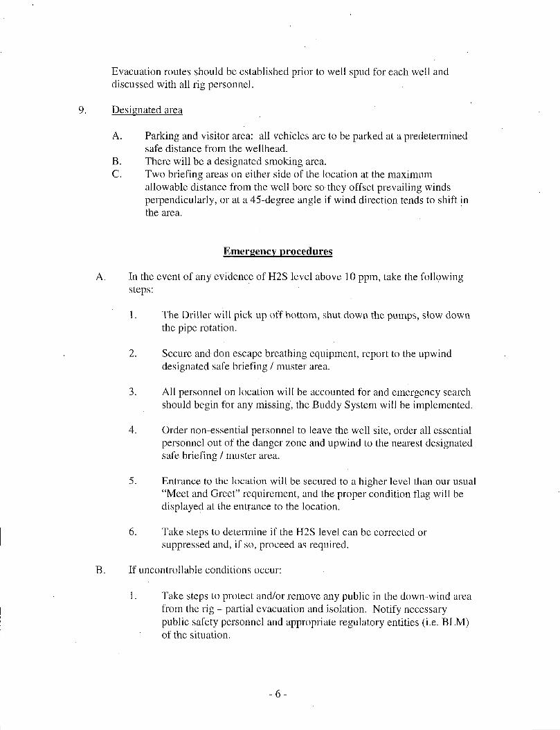
Evacuation routes should be established prior to well spud for each well and discussed with all rig personnel.
Designated area
A. Parking and visitor area: all vehicles are to be parked at a predetermined safe distance from the wellhead.
B. There will be a designated smoking area. C. Two briefing areas on either side of the location at the maximum
allowable distance from the well bore so they offset prevailing winds perpendicularly, or at a 45-degree angle if wind direction tends to shift in the area.
Emergency procedures
A. In the event of any evidence of H2S level above 10 ppm, take the following steps:
1. The Driller will pick up off bottom, shut down the pumps, slow down the pipe rotation.
2. Secure and don escape breathing equipment, report to the upwind designated safe briefing / muster area.
3. All personnel on location will be accounted for and emergency search should begin for any missing, the Buddy System will be implemented.
4. Order non-essential personnel to leave the well site, order all essential personnel out of the danger zone and upwind to the nearest designated safe briefing / muster area.
5. Entrance to the location will be secured to a higher level than our usual "Meet and Greet" requirement, and the proper condition flag will be displayed at the entrance to the location.
6. Take steps to determine if the H2S level can be corrected or suppressed and, if so, proceed as required.
B. If uncontrollable conditions occur:
1. Take steps to protect and/or remove any public in the down-wind area from the rig - partial evacuation and isolation. Notify necessary public safety personnel and appropriate regulatory entities (i.e. BLM) of the situation.

2. Remove all personnel to the nearest upwind designated safe briefing / muster area or off location.
3. Notify public safety personnel of safe briefing / muster area.
4. An assigned crew member will blockade the entrance to the location. No unauthorized personnel will be allowed entry to the location.
5. Proceed with best plan (at the time) to regain control of the well. Maintain tight security and safety procedures.
C. Responsibility:
1. Designated personnel.
a. Shall be responsible for the total implementation of this plan. b. Shall be in complete command during any emergency. c. Shall designate a back-up.
All personnel: 1. On alarm, don escape unit and report to the nearest upwind designated safe briefing / muster area upw
2. Check status of personnel (buddy system). 3. Secure breathing equipment. 4. Await orders from supervisor.
Drill site manager: 1.
2.
3. 4.
Don escape unit if necessary and report to nearest upwind designated safe briefing / muster area. Coordinate preparations of individuals to return to point of release with tool pusher and driller (using the buddy system). Determine H2S concentrations. Assess situation and take control measures.
Tool pusher: 1.
2.
3. 4.
Don escape unit Report to up nearest upwind designated safe briefing / muster area. Coordinate preparation of individuals to return to point of release with tool pusher drill site manager (using the buddy system). Determine H2S concentration. Assess situation and take control measures.
Driller: Don escape unit, shut down pumps, continue rotating DP.
-7 -

2. Check monitor for point of release. 3. Report to nearest upwind designated safe briefing /
muster area. 4. Check status of personnel (in an attempt to rescue,
use the buddy system). 5. Assigns least essential person to notify Drill Site
Manager and tool pusher by quickest means in case of their absence.
6. Assumes the responsibilities of the Drill Site Manager and tool pusher until they arrive should they be absent.
Derrick man Floor man #1 Floor man #2
Will remain in briefing / muster area until instructed by supervisor.
Mud engineer: 1. Report to nearest upwind designated safe briefing / muster area.
2. When instructed, begin check of mud for ph and H2S level. (Garett gas train.)
Safety personnel: Mask up and check status of all personnel and secure operations as instructed by drill site manager.
Taking a kick
When taking a kick during an H2S emergency, all personnel will follow standard Well control procedures after reporting to briefing area and masking up.
Open-hole logging
All unnecessary personnel off floor. Drill Site Manager and safety personnel should monitor condition, advise status and determine need for use of air equipment.
Running casing or plugging
Following the same "tripping" procedure as above. Drill Site Manager and safety personnel should determine if all personnel have access to protective equipment.
- 8 -

Ignition procedures
The decision to ignite the well is the responsibility of the operator (Oxy Drilling Management). The decision should be made only as a last resort and in a situation where it is clear that:
1. Human life and property are endangered. 2. There is no hope controlling the blowout under the prevailing conditions
at the well.
Instructions for igniting the well
1. Two people are required for the actual igniting operation. They must wear self-contained breathing units and have a safety rope attached. One man (tool pusher or safety engineer) will check the atmosphere for explosive gases with the gas monitor. The other man is responsible for igniting the well.
2. Primary method to ignite: 25 mm flare gun with range of approximately 500 feet.
3. Ignite upwind and do not approach any closer than is warranted. 4. Select the ignition site best for protection, and which offers an easy escape
route. 5. Before firing, check for presence of combustible gas. 6. After lighting, continue emergency action and procedure as before. 7. All unassigned personnel will remain in briefing area until instructed by
supervisor or directed by the Drill Site Manager.
Remember: After well is ignited, burning hydrogen sulfide will convert to sulfur dioxide, which is also highly toxic. Do not assume the area is safe after the well is ignited.
-9-

Status check list
Note: All items on this list must be completed before drilling to production casing point.
1. H2S sign at location entrance.
2. Two (2) wind socks located as required.
3. Four (4) 30-minute positive pressure air packs (2 at each Briefing area) on location for all rig personnel and mud loggers.
4. Air packs inspected and ready for use.
5. Cascade system and hose line hook-up as needed.
6. Cascade system for refilling air bottles as needed.
7. Condition flag on location and ready for use.
8. H2S detection system hooked up and tested.
9. H2S alarm system hooked up and tested.
10. Hand operated H2S detector with tubes on location.
11. 1 - 100' length of nylon rope on location.
12. All rig crew and supervisors trained as required.
13. All outside service contractors advised of potential H2S hazard on well.
14. No smoking sign posted and a designated smoking area identified.
15. Calibration of all H2S equipment shall be noted on the IADC report.
- 10-

Procedural check list during H2S events
Perform each tour:
1. Check fire extinguishers to see that they have the proper charge.
2. Check breathing equipment to ensure that it in proper working order.
3. Make sure all the H2S detection system is operative.
Perform each week:
1. Check each piece of breathing equipment to make sure that demand or forced air regulator is working. This requires that the bottle be opened and the mask assembly be put on tight enough so that when you inhale, you receive air or feel air flow.
2. BOP skills (well control drills).
3. Check supply pressure on BOP accumulator stand by source.
4. Check breathing equipment mask assembly to see that straps are loosened and turned back, ready to put on.
5. Check pressure on breathing equipment air bottles to make sure they are charged to full volume. ( Air quality checked for proper air grade "D" before bringing to location)
6. Confirm pressure on all supply air bottles.
7. Perform breathing equipment drills with on-site personnel.
8. Check the following supplies for availability.
A. Emergency telephone list. B. Hand operated H2S detectors and tubes.

General evacuation plan
1. When the company approved supervisor (Drill Site Manager, consultant, rig pusher, or driller) determines the H2S gas cannot be limited to the well location and the public will be involved, he will activate the evacuation plan.
2. • Drill Site Manager or designee will notify local government agency that a hazardous condition exists and evacuation needs to be implemented.
3. Company or contractor safety personnel that have been trained in the use of H2S detection equipment and self-contained breathing equipment will monitor H2S concentrations, wind directions, and area of exposure. They will delineate the outer perimeter of the hazardous gas area. Extension to the evacuation area will be determined from information gathered.
4. Law enforcement personnel (state police, police dept., fire dept., and sheriff's dept.) Will be called to aid in setting up and maintaining road blocks. Also, they will aid in evacuation of the public if necessary.
5. After the discharge of gas has been controlled, company safety personnel will determine when the area is safe for re-entry.
Important: Law enforcement personnel will not be asked to come into a contaminated area. Their assistance will be limited to uncontaminated areas. Constant radio contact will be maintained with them.
- 12-

Emergency actions
Well blowout - if emergency
1. Evacuate all personnel to "Safe Briefing / Muster Areas" or off location if needed.
2. If sour gas - evacuate rig personnel.
3. If sour gas - evacuate public within 3000 ft radius of exposure.
4. Don SCBA and shut well in if possible using the buddy system.
5. Notify Drilling Superintendent and call 911 for emergency help (fire dept and ambulance) if needed.
6. Implement the Blowout Contingency Plan, and Drilling Emergency Action Plan.
6. Give first aid as needed.
Person down location/facility
1. If immediately possible, contact 911. Give location and wait for confirmation.
2. Don SCBA and perform rescue operation using buddy system.
- 13 -

Toxic effects of hydrogen sulfide
Hydrogen sulfide is extremely toxic. The acceptable ceiling concentration for eight-hour exposure is 10 ppm, which is .001% by volume. Hydrogen sulfide is heavier than air (specific gravity - 1.192) and colorless. It forms an explosive mixture with air between 4.3 and 46.0 percent by volume. Hydrogen sulfide is almost as toxic as hydrogen cyanide and is between five and six times more toxic than carbon monoxide. Toxicity data for hydrogen sulfide and various other gases are compared in table i . Physical effects at various hydrogen sulfide exposure levels are shown in table i i .
Table i Toxicity of various gases
Common Chemical Specific Threshold Hazardous Lethal concentration name formula gravity limit limit (3)
(sc=l) (1) (2) Hydrogen Hen 0.94 10 ppm 150 ppm/hr 300 ppm Cyanide
300 ppm
Hydrogen H2S 1.18 10 ppm 250 ppm/hr 600 ppm Sulfide Sulfur So2 2.21 5 ppm - 1000 ppm Dioxide
1000 ppm
Chlorine C12 2.45 1 ppm 4 ppm/hr 1000 ppm
Carbon Co 0.97 50 ppm 400 ppm/hr 1000 ppm Monoxide Carbon Co2 1.52 5000 ppm 5% 10% Dioxide
5000 ppm
Methane .Ch4 0.55 90,000 ppm Combustible above 5% in air
1) threshold limit - concentration at which it is believed that all workers may be repeatedly exposed day after day without adverse effects.
2) hazardous limit - concentration that will cause death with short-term exposure.
3) lethal concentration - concentration that will cause death with short-term exposure.
Toxic effects of hydrogen sulfide
Table ii Physical effects of hydrogen sulfide
Concentration Physical effects Percent (%) Ppm Grains
100 std. Ft3* 0.001 <10 00.65 Obvious and unpleasant odor.
- 14-

0.002 10 01.30
0.010 100 06.48
0.020 200 12.96
0.050 500 32.96
0.070 700 45.36
0.100 1000 64.30
*at 15.00 psiaand 60'f.
Safe for 8 hours of exposure.
Kill smell in 3 - 15 minutes. May sting eyes and throat. Kills smell shortly; stings eyes and throat.
Dizziness; breathing ceases in a few minutes; needs prompt artificial respiration. Unconscious quickly; death will result if not rescued promptly. Unconscious at once; followed by death within minutes.
- 15 -

Use of self-contained breathing equipment (SCBA)
1. Written procedures shall be prepared covering safe use of SCBA's in dangerous atmosphere, which might be encountered in normal operations or in emergencies. Personnel shall be familiar with these procedures and the available SCBA.
2 SCBA's shall be inspected frequently at random to insure that they are properly used, cleaned, and maintained.
3. Anyone who may use the SCBA's shall be trained in how to insure proper face-piece to face seal. They shall wear SCBA's in normal air and then wear them in a test atmosphere, (note: such items as facial hair {beard or sideburns} and eyeglasses will not allow proper seal.) Anyone that may be reasonably expected to wear SCBA's should have these items removed before entering a toxic atmosphere. A special mask must be obtained for anyone who must wear eyeglasses or contact lenses.
4. Maintenance and care of SCBA's:
a. A program for maintenance and care of SCBA's shall include the following: 1. Inspection for defects, including leak checks. 2. Cleaning and disinfecting. 3. Repair. 4. Storage.
b. Inspection, self-contained breathing apparatus for emergency use shall be inspected monthly. 1. Fully charged cylinders. 2. Regulator and warning device operation. 3. Condition of face piece and connections. 4. Rubber parts shall be maintained to keep them pliable and prevent
deterioration.
c. Routinely used SCBA's shall be collected, cleaned and disinfected as frequently as necessary to insure proper protection is provided.
5. Persons assigned tasks that requires use of self-contained breathing equipment shall be certified physically fit (medically cleared) for breathing equipment usage at least annually.
6. SCBA's should be worn when:
A. Any employee works near the top or on top of any tank unless test reveals less than 10 ppm of H2S.
- 16-

When breaking out any line where H2S can reasonably be expected.
When sampling air in areas to determine if toxic concentrations of H2S exists.
When working in areas where over 10 ppm H2S has been detected.
At any time there is a doubt as to the H2S level in the area to be entered.
Rescue First aid for H2S poisoning
Do not panic!
Remain calm - think!
1. Don SCBA breathing equipment.
2. Remove victim(s) utilizing buddy system to fresh air as quickly as possible, (go up-wind from source or at right angle to the wind. Not.down wind.)
3. Briefly apply chest pressure - arm lift method of artificial respiration to clean the victim's lungs and to avoid inhaling any toxic gas directly from the victim's lungs.
4. Provide for prompt transportation to the hospital, and continue giving artificial respiration if needed.
5. Hospital(s) or medical facilities need to be informed, before-hand, of the possibility of H2S gas poisoning - no matter how remote the possibility is.
6. Notify emergency room personnel that the victim(s) has been exposed to H2S gas.
Besides basic first aid, everyone on location should have a good working knowledge of artificial respiration.
B.
C.
D.
E.
Revised CM 6/27/2012
- 17 -
![RECEIVED ]ocdimage.emnrd.state.nm.us/imaging/filestore/artesia/WF/255551/... · RECEIVED ] MAR 2 6 2014 APPLICATION FOR PERMIT TO DRILL OR REENTER FORM APPROVED OMB No. 1004-0137](https://img.pdfslide.us/doc/110x75/5ca908c288c993d8488be267/received-received-mar-2-6-2014-application-for-permit-to-drill-or-reenter.jpg)