Embed Size (px)
Citation preview
JLAB-TN-09-029 C100 Cryomodule Vacuum Vessel Structural Analysis-Addendum II to JLAB-TN-07-081
1/38
C100 Cryomodule Vacuum Vessel Structural Analysis − Addendum II to JLAB-TN-07-081
Gary G. Cheng, Edward F. Daly, and Mark Wiseman
Introduction
The C100 cryomodule (CM) vacuum vessel structural analysis per ASME Boiler & Pressure Vessel code (BPVC) [1] requirements was addressed in JLAB-TN-07-081 [2] and JLAB-TN-09-007 [3]. This technical note (TN) is to amend the previous two TNs in a few aspects:
(1) More comprehensive ASME pressure vessel code analyses are conducted in consideration of the complicated loading condition for vacuum vessel,
(2) Since the C100 CM design is finalized, the weights of components to be supported by the vacuum vessel are found to be more than the previously estimated. Most calculations are affected.
(3) The manufacturer suggested some design changes that affect weld details. They are addressed in this TN.
In the summary of this TN, a chronological list of editions in all three TNs on vacuum vessel
structural analysis is given to facilitate tracking of changes. This TN is primarily aimed to implement the procedure of ASME BPVC analysis per Section VIII, Division 1 rules (S8D1), with reference to pertinent Division 2 rules/definitions. A short discussion of scenarios to apply either Division 1 or 2 rules in analyzing pressure vessel is presented in Appendix 1.
I. Allowable Stresses and Required Wall Thicknesses (UG-22, UG-23, and UG-28) The estimated weights used in JLAB-TN-07-081 and JLAB-TN-09-007 are based on SNS
CM. The weights for C100 CM components are updated as follows:
Part name volumes, in3 weight Single Nb cavity 172.6 53.51 lbs 8 Nb cavities 1,380.8 428 lbs Inner mag shield (all 8 modules) 219.2 69 lbs Outer mag shield 1,424.9 450 lbs Thermal shield 2,556.3 826 lbs SS parts (spaceframe, HV, headers, tuners, rods & brackets, etc.) 13,209.0 3,817 lbs
Spaceframe & associated components 5,591 lbs Supply End Can 3,913.6 1,131 lbs Return End Can 3,653.3 1,056 lbs
Other loads include: Weight of single waveguide assembly: 190 lbf
JLAB-TN-09-029 C100 Cryomodule Vacuum Vessel Structural Analysis-Addendum II to JLAB-TN-07-081
2/38
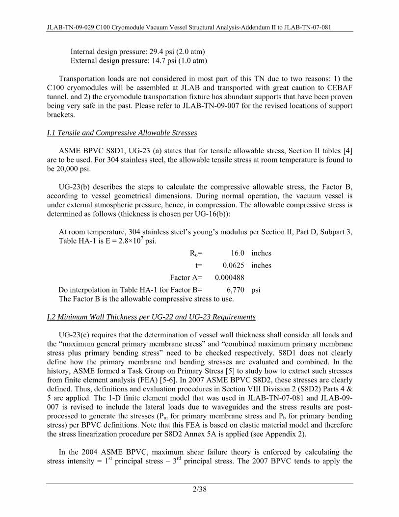
Internal design pressure: 29.4 psi (2.0 atm) External design pressure: 14.7 psi (1.0 atm)
Transportation loads are not considered in most part of this TN due to two reasons: 1) the
C100 cryomodules will be assembled at JLAB and transported with great caution to CEBAF tunnel, and 2) the cryomodule transportation fixture has abundant supports that have been proven being very safe in the past. Please refer to JLAB-TN-09-007 for the revised locations of support brackets.
I.1 Tensile and Compressive Allowable Stresses
ASME BPVC S8D1, UG-23 (a) states that for tensile allowable stress, Section II tables [4]
are to be used. For 304 stainless steel, the allowable tensile stress at room temperature is found to be 20,000 psi.
UG-23(b) describes the steps to calculate the compressive allowable stress, the Factor B,
according to vessel geometrical dimensions. During normal operation, the vacuum vessel is under external atmospheric pressure, hence, in compression. The allowable compressive stress is determined as follows (thickness is chosen per UG-16(b)):
At room temperature, 304 stainless steel’s young’s modulus per Section II, Part D, Subpart 3, Table HA-1 is E = 2.8×10⁷ psi.
Ro= 16.0 inches t= 0.0625 inches
Factor A= 0.000488Do interpolation in Table HA-1 for Factor B= 6,770 psi The Factor B is the allowable compressive stress to use.
I.2 Minimum Wall Thickness per UG-22 and UG-23 Requirements UG-23(c) requires that the determination of vessel wall thickness shall consider all loads and
the “maximum general primary membrane stress” and “combined maximum primary membrane stress plus primary bending stress” need to be checked respectively. S8D1 does not clearly define how the primary membrane and bending stresses are evaluated and combined. In the history, ASME formed a Task Group on Primary Stress [5] to study how to extract such stresses from finite element analysis (FEA) [5-6]. In 2007 ASME BPVC S8D2, these stresses are clearly defined. Thus, definitions and evaluation procedures in Section VIII Division 2 (S8D2) Parts 4 & 5 are applied. The 1-D finite element model that was used in JLAB-TN-07-081 and JLAB-09-007 is revised to include the lateral loads due to waveguides and the stress results are post-processed to generate the stresses (Pm for primary membrane stress and Pb for primary bending stress) per BPVC definitions. Note that this FEA is based on elastic material model and therefore the stress linearization procedure per S8D2 Annex 5A is applied (see Appendix 2).
In the 2004 ASME BPVC, maximum shear failure theory is enforced by calculating the
stress intensity = 1st principal stress – 3rd principal stress. The 2007 BPVC tends to apply the

JLAB-TN-09-029 C100 Cryomodule Vacuum Vessel Structural Analysis-Addendum II to JLAB-TN-07-081
3/38
distortion energy failure theory that requires the calculation of von Mises stress. From the 1-D FEA, nodal stress components are calculated. The three principal stresses are obtained by solving a cubic equation in this form:
0 (1) The I1, I2, I3 are stress invariants evaluated from stress components and the roots to this
equation can be derived from Cardano’s formula, see Appendix 2. The three roots are sorted to obtain the 1st , 2nd, and 3rd principal stresses: σ1, σ2, and σ3. Stress intensity is equal to σ1- σ3. The von Mises stress is:
(2)
The finite element model was run for both internal pressure and external pressure cases with normal loads. Transverse shear force, bending moment, and stress plots are attached in Appendix 3 for information. The purpose of these FEA is to determine the required vacuum vessel shell thickness per UG-23(c). It is noted that UG-16(b) states that in general, the minimum wall thickness for shells and heads shall be no less than 0.0625". So there is no need to investigate thicknesses that are lower than 0.0625". The 0.0625" thickness would be a good initial guess of the required wall thickness. In other words, if the vessel with 0.0625" thickness proves to be safe per UG-23(c) conditions, then the required minimum shell thickness is 0.0625".
The primary membrane stresses, Pm, and the combined primary membrane stress and primary
bending stress, Pm + Pb, for the case of t = 0.0625" are given in Table 1. The Pm’s are much lower than tensile allowable stress of 20,000 psi and compressive allowable stress of 6,770 psi. The Pm+Pb’s are not much different from Pm’s and they are lower than 1.5 times of the tensile or compressive allowable stresses. Therefore, combining the requirements in UG-16(b) and UG-23(c), the required minimum shell thickness is tr = 0.0625".
Table 1 Summary of stresses in vacuum vessel with shell thickness = 0.0625"
Cases t = 0.0625"
1st principal
2nd principal
3rd principal
stress intensity
von Mises
Pin = 2 atm, top of shell, Pm 7,485 5,750 -29 7,955 6,908Pin = 2 atm, top of shell, Pm+Pb 7,485 5,754 -29 7,955 6,907Pin = 2 atm, bottom of shell, Pm 7,485 3,364 -29 8,186 7,218Pin = 2 atm, bottom of shell, Pm+Pb 7,485 3,363 -29 8,186 7,219Pext = 1 atm, top of shell, Pm 1,036 -1,561 -3,760 4,795 4,153Pext = 1 atm, top of shell, Pm+Pb 1,037 -1,561 -3,760 4,796 4,154Pext = 1 atm, bottom of shell, Pm 620 -3,748 -3,924 4,382 3,887Pext = 1 atm, bottom of shell, Pm+Pb 620 -3,748 -3,928 4,381 3,889 The actual design thickness for vacuum vessel shell is t = 0.25". For information, the Pm’s
and Pm+Pb’s are evaluated for vessel with real design thickness and stress results are presented in
JLAB-TN-09-029 C100 Cryomodule Vacuum Vessel Structural Analysis-Addendum II to JLAB-TN-07-081
4/38
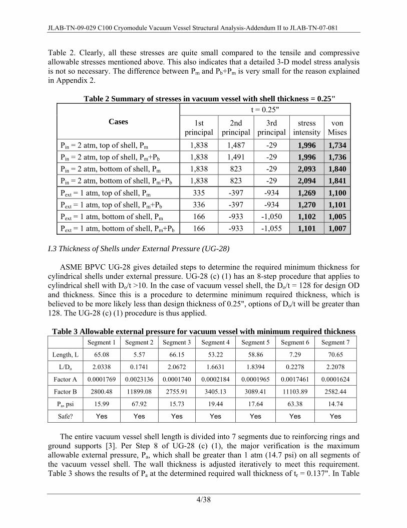
Table 2. Clearly, all these stresses are quite small compared to the tensile and compressive allowable stresses mentioned above. This also indicates that a detailed 3-D model stress analysis is not so necessary. The difference between Pm and Pb+Pm is very small for the reason explained in Appendix 2.
Table 2 Summary of stresses in vacuum vessel with shell thickness = 0.25"
Cases t = 0.25"
1st principal
2nd principal
3rd principal
stress intensity
von Mises
Pin = 2 atm, top of shell, Pm 1,838 1,487 -29 1,996 1,734Pin = 2 atm, top of shell, Pm+Pb 1,838 1,491 -29 1,996 1,736Pin = 2 atm, bottom of shell, Pm 1,838 823 -29 2,093 1,840Pin = 2 atm, bottom of shell, Pm+Pb 1,838 823 -29 2,094 1,841Pext = 1 atm, top of shell, Pm 335 -397 -934 1,269 1,100Pext = 1 atm, top of shell, Pm+Pb 336 -397 -934 1,270 1,101Pext = 1 atm, bottom of shell, Pm 166 -933 -1,050 1,102 1,005Pext = 1 atm, bottom of shell, Pm+Pb 166 -933 -1,055 1,101 1,007
I.3 Thickness of Shells under External Pressure (UG-28)
ASME BPVC UG-28 gives detailed steps to determine the required minimum thickness for cylindrical shells under external pressure. UG-28 (c) (1) has an 8-step procedure that applies to cylindrical shell with Do/t >10. In the case of vacuum vessel shell, the Do/t = 128 for design OD and thickness. Since this is a procedure to determine minimum required thickness, which is believed to be more likely less than design thickness of 0.25", options of Do/t will be greater than 128. The UG-28 (c) (1) procedure is thus applied.
Table 3 Allowable external pressure for vacuum vessel with minimum required thickness
Segment 1 Segment 2 Segment 3 Segment 4 Segment 5 Segment 6 Segment 7
Length, L 65.08 5.57 66.15 53.22 58.86 7.29 70.65
L/Do 2.0338 0.1741 2.0672 1.6631 1.8394 0.2278 2.2078
Factor A 0.0001769 0.0023136 0.0001740 0.0002184 0.0001965 0.0017461 0.0001624
Factor B 2800.48 11899.08 2755.91 3405.13 3089.41 11103.89 2582.44
Pa, psi 15.99 67.92 15.73 19.44 17.64 63.38 14.74
Safe? Yes Yes Yes Yes Yes Yes Yes
The entire vacuum vessel shell length is divided into 7 segments due to reinforcing rings and
ground supports [3]. Per Step 8 of UG-28 (c) (1), the major verification is the maximum allowable external pressure, Pa, which shall be greater than 1 atm (14.7 psi) on all segments of the vacuum vessel shell. The wall thickness is adjusted iteratively to meet this requirement. Table 3 shows the results of Pa at the determined required wall thickness of tr = 0.137". In Table

JLAB-TN-09-029 C100 Cryomodule Vacuum Vessel Structural Analysis-Addendum II to JLAB-TN-07-081
5/38
4, the allowable external pressures for vessel with design thickness of t = 0.25" are shown for information.
Table 4 Allowable external pressure for vacuum vessel with design thickness
Segment 1 Segment 2 Segment 3 Segment 4 Segment 5 Segment 6 Segment 7 Length, L 65.08 5.57 66.15 53.22 58.86 7.29 70.65
L/Do 2.0338 0.1741 2.0672 1.6631 1.8394 0.2278 2.2078 Factor A 0.0004345 0.0058817 0.0004270 0.0005377 0.0004833 0.0044221 0.0003983 Factor B 6180.92 13817.91 6095.83 7255.65 6718.00 13430.38 5759.90
Pa, psi 35.28 78.88 34.80 41.42 38.35 76.67 32.88 Safe? Yes Yes Yes Yes Yes Yes Yes The conclusion from this study is that to meet UG-28 requirements on allowable external
pressure, the minimum required shell thickness is 0.137". The design thickness of 0.25" is found to be sufficient. The required wall thickness is useful in subsequent reinforcement area code calculation per UG-37.
II. Reinforcement Area at Welds for Openings (UG-36, UG-37, UG-40, UG-41, UW-15, and UW-16)
II.1 Reinforcement Areas for Vessel under Internal Pressure
There are welds at waveguide ports, instrumentation ports, accesses port, and tuner ports.
The steps for determining whether reinforcement areas are needed for these welded openings are detailed in UG-37. A prelude to the reinforcement area calculation is the determination of required nozzle wall thickness, i.e. trn. The rules governing nozzle wall thickness are in UG-16(b) and UG-45. For nozzles subjected to internal pressure, if no other mechanical loads but pressure load exist, UG-45(a) can be conveniently carried out by use of formulas given in UG-27 for cylindrical nozzles. Please note that waveguides ports carry waveguides [2]. The nozzles are seamless so that the weld joint efficiency is 1.0. Table 5 shows the detailed calculations for trn’s:
Table 5 Determining trn for nozzles under internal pressure
center waveguide
port
side waveguide
port
Instrument -ation port
access port
tuner port
ID of nozzle 14.40 11.21 12.37 5.834 4.12
Inner radius of nozzle 7.2 5.61 6.19 2.91 2.06
Vertical force, Fy, lbf 380 190 0 0 0
Distance from C.G. to interface, in 13 13
Bending moment, Mz, lbf-in 4940 2470 0 0 0
Nozzle thickness by UG-45(a) 0.011 0.008 0.009 0.004 0.003
Nozzle thickness by UG-45(b)(1), UG-16(b) 0.0625 0.0625 0.0625 0.0625 0.0625
JLAB-TN-09-029 C100 Cryomodule Vacuum Vessel Structural Analysis-Addendum II to JLAB-TN-07-081
6/38
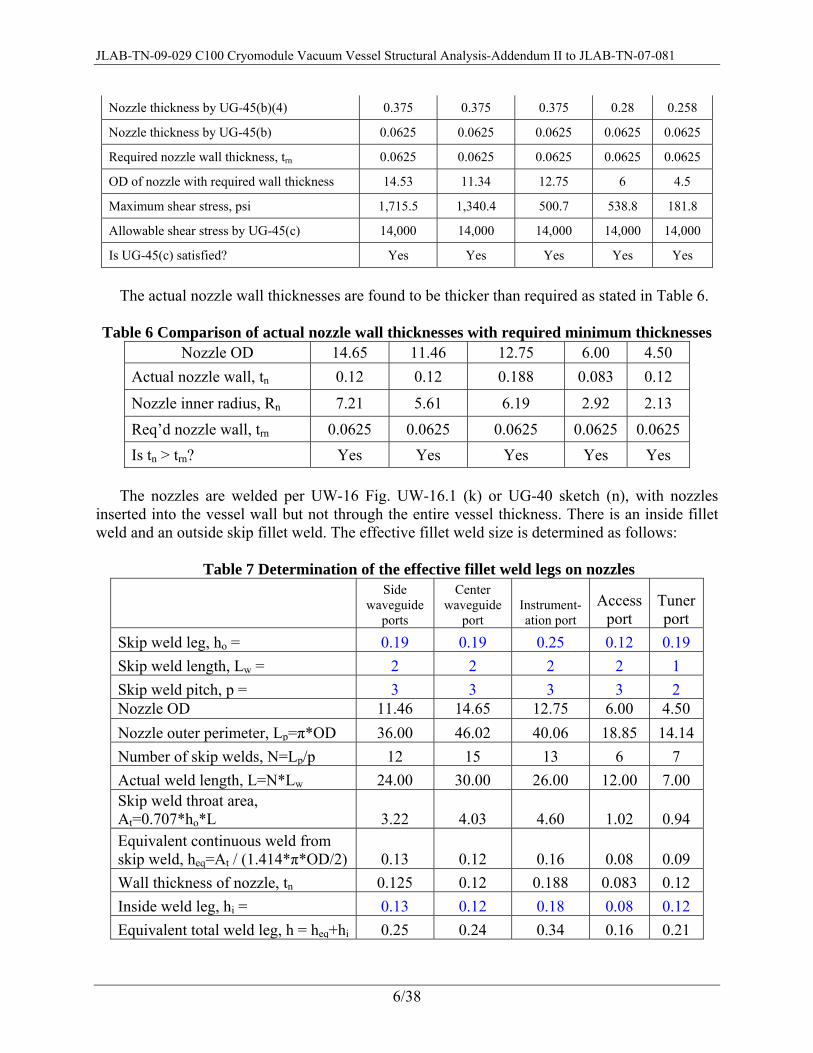
Nozzle thickness by UG-45(b)(4) 0.375 0.375 0.375 0.28 0.258
Nozzle thickness by UG-45(b) 0.0625 0.0625 0.0625 0.0625 0.0625
Required nozzle wall thickness, trn 0.0625 0.0625 0.0625 0.0625 0.0625
OD of nozzle with required wall thickness 14.53 11.34 12.75 6 4.5
Maximum shear stress, psi 1,715.5 1,340.4 500.7 538.8 181.8
Allowable shear stress by UG-45(c) 14,000 14,000 14,000 14,000 14,000
Is UG-45(c) satisfied? Yes Yes Yes Yes Yes
The actual nozzle wall thicknesses are found to be thicker than required as stated in Table 6.
Table 6 Comparison of actual nozzle wall thicknesses with required minimum thicknesses
Nozzle OD 14.65 11.46 12.75 6.00 4.50 Actual nozzle wall, tn 0.12 0.12 0.188 0.083 0.12
Nozzle inner radius, Rn 7.21 5.61 6.19 2.92 2.13 Req’d nozzle wall, trn 0.0625 0.0625 0.0625 0.0625 0.0625 Is tn > trn? Yes Yes Yes Yes Yes
The nozzles are welded per UW-16 Fig. UW-16.1 (k) or UG-40 sketch (n), with nozzles
inserted into the vessel wall but not through the entire vessel thickness. There is an inside fillet weld and an outside skip fillet weld. The effective fillet weld size is determined as follows:
Table 7 Determination of the effective fillet weld legs on nozzles
Side waveguide
ports
Center waveguide
port Instrument-ation port
Access port
Tuner port
Skip weld leg, ho = 0.19 0.19 0.25 0.12 0.19 Skip weld length, Lw = 2 2 2 2 1 Skip weld pitch, p = 3 3 3 3 2 Nozzle OD 11.46 14.65 12.75 6.00 4.50 Nozzle outer perimeter, Lp=π*OD 36.00 46.02 40.06 18.85 14.14 Number of skip welds, N=Lp/p 12 15 13 6 7 Actual weld length, L=N*Lw 24.00 30.00 26.00 12.00 7.00 Skip weld throat area, At=0.707*ho*L 3.22 4.03 4.60 1.02 0.94 Equivalent continuous weld from skip weld, heq=At / (1.414*π*OD/2) 0.13 0.12 0.16 0.08 0.09 Wall thickness of nozzle, tn 0.125 0.12 0.188 0.083 0.12 Inside weld leg, hi = 0.13 0.12 0.18 0.08 0.12 Equivalent total weld leg, h = heq+hi 0.25 0.24 0.34 0.16 0.21

JLAB-TN-09-029 C100 Cryomodule Vacuum Vessel Structural Analysis-Addendum II to JLAB-TN-07-081
7/38
Per I.2, the required minimum shell thickness for vacuum vessel under internal pressure is tr = 0.0625". Together with the information on trn’s, UG-37 procedure can now be implemented to determine whether additional reinforcement area is required at the nozzle welds. A few pertinent parameters in UG-37(a) are determined first:
F = 1 for all nozzles except tuner ports. F = 0.5 for tuner ports assuming θ=90°. fr1 = 1 for all nozzles because they are welded as UG-40 sketch (n). fr2 = Sn/Sv = 1 because tensile strength (see UG-23(a)) of nozzle and vessel materials are the
same. fr3 = Sn/Sv = 1. E1 = 1 because no nozzles will pass through other welds. The longitudinal weld (PAW
autogenous weld) is “clearly identifiable” and can be avoided to overlap with openings. t = 0.25" is the specified vacuum vessel wall thickness. For the tuner ports, the equivalent chord length, which is used in place of diameter of
opening for a tuner port subjected to internal pressure, is determined as follows:
Rm = R+tr/2 = 15.78 inches L = 8 inches
α1 = cos-1((L+Rn)/Rm) = 50.40°
α2 = cos-1((L-Rn)/Rm) = 67.89°
α = α2- α1 = 17.49°
d = 2 Rm (1-cos2(α/2))1/2 = 4.80 inches
Table 8 lists the steps toward deciding whether reinforcement area is needed when vacuum
vessel is subjected to internal pressure.
Table 8 Determining reinforcement area for vacuum vessel subjected to internal pressure
center waveguide
port
side waveguide
port Instrument -ation port
access port
tuner port
diameter of opening d= 14.40 11.22 12.37 5.834 4.80 wall thickness of nozzle tn= 0.12 0.12 0.188 0.083 0.12
required nozzle thickness trn= 0.0625 0.0625 0.0625 0.0625 0.0625 A= 0.90 0.70 0.77 0.36 0.15
A1 from 1st equation is: 2.70 2.10 2.32 1.09 1.05
A1 from 2nd equation is: 0.14 0.14 0.16 0.12 0.16 larger A1 from above two = 2.70 2.10 2.32 1.09 1.05
A2 from 1st equation is: 0.0719 0.0719 0.1569 0.0256 0.0719
A2 from 2nd equation is: 0.0345 0.0345 0.1180 0.0085 0.0345smaller A2 from above two = 0.0345 0.0345 0.1180 0.0085 0.0345
JLAB-TN-09-029 C100 Cryomodule Vacuum Vessel Structural Analysis-Addendum II to JLAB-TN-07-081
8/38
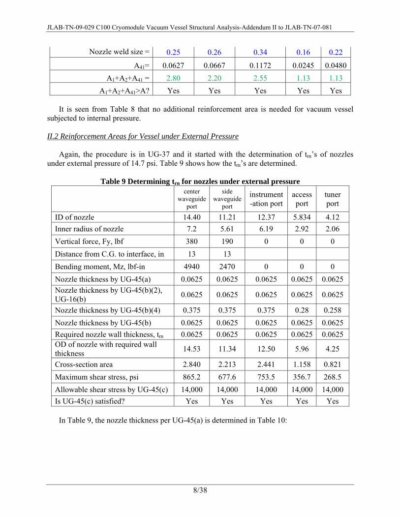
Nozzle weld size = 0.25 0.26 0.34 0.16 0.22
A41= 0.0627 0.0667 0.1172 0.0245 0.0480A1+A2+A41 = 2.80 2.20 2.55 1.13 1.13
A1+A2+A41>A? Yes Yes Yes Yes Yes It is seen from Table 8 that no additional reinforcement area is needed for vacuum vessel
subjected to internal pressure.
II.2 Reinforcement Areas for Vessel under External Pressure Again, the procedure is in UG-37 and it started with the determination of trn’s of nozzles
under external pressure of 14.7 psi. Table 9 shows how the trn’s are determined.
Table 9 Determining trn for nozzles under external pressure
center waveguide
port
side waveguide
port
instrument -ation port
access port
tuner port
ID of nozzle 14.40 11.21 12.37 5.834 4.12 Inner radius of nozzle 7.2 5.61 6.19 2.92 2.06 Vertical force, Fy, lbf 380 190 0 0 0 Distance from C.G. to interface, in 13 13 Bending moment, Mz, lbf-in 4940 2470 0 0 0 Nozzle thickness by UG-45(a) 0.0625 0.0625 0.0625 0.0625 0.0625 Nozzle thickness by UG-45(b)(2), UG-16(b) 0.0625 0.0625 0.0625 0.0625 0.0625
Nozzle thickness by UG-45(b)(4) 0.375 0.375 0.375 0.28 0.258 Nozzle thickness by UG-45(b) 0.0625 0.0625 0.0625 0.0625 0.0625 Required nozzle wall thickness, trn 0.0625 0.0625 0.0625 0.0625 0.0625 OD of nozzle with required wall thickness 14.53 11.34 12.50 5.96 4.25
Cross-section area 2.840 2.213 2.441 1.158 0.821 Maximum shear stress, psi 865.2 677.6 753.5 356.7 268.5 Allowable shear stress by UG-45(c) 14,000 14,000 14,000 14,000 14,000 Is UG-45(c) satisfied? Yes Yes Yes Yes Yes In Table 9, the nozzle thickness per UG-45(a) is determined in Table 10:
JLAB-TN-09-029 C100 Cryomodule Vacuum Vessel Structural Analysis-Addendum II to JLAB-TN-07-081
9/38
Table 10 Nozzles under external pressure and lateral load: thickness per UG-45(a)
center waveguide
port
side waveguide
port
instrument-ation port
access port
tuner port
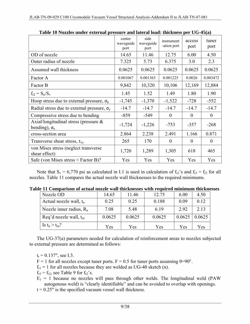
OD of nozzle 14.65 11.46 12.75 6.00 4.50 Outer radius of nozzle 7.325 5.73 6.375 3.0 2.3
Assumed wall thickness 0.0625 0.0625 0.0625 0.0625 0.0625
Factor A 0.001067 0.001363 0.001225 0.0026 0.003472
Factor B 9,842 10,320 10,106 12,169 12,884
fr2 = Sn/Sv 1.45 1.52 1.49 1.80 1.90 Hoop stress due to external pressure, σz -1,745 -1,370 -1,522 -728 -552 Radial stress due to external pressure, σy -14.7 -14.7 -14.7 -14.7 -14.7 Compressive stress due to bending -859 -549 0 0 0 Axial/longitudinal stress (pressure & bending), σx
-1,724 -1,226 -753 -357 -268
cross-section area 2.864 2.238 2.491 1.166 0.871 Transverse shear stress, τxy 265 170 0 0 0 von Mises stress (neglect transverse shear effect) 1,720 1,289 1,305 618 465
Safe (von Mises stress < Factor B)? Yes Yes Yes Yes Yes Note that Sv = 6,770 psi as calculated in I.1 is used in calculation of fr2’s and fr3 = fr2 for all
nozzles. Table 11 compares the actual nozzle wall thicknesses to the required minimums.
Table 11 Comparison of actual nozzle wall thicknesses with required minimum thicknesses Nozzle OD 14.65 11.46 12.75 6.00 4.50 Actual nozzle wall, tn 0.25 0.25 0.188 0.09 0.12 Nozzle inner radius, Rn 7.08 5.48 6.19 2.92 2.13 Req’d nozzle wall, trn 0.0625 0.0625 0.0625 0.0625 0.0625Is tn > trn? Yes Yes Yes Yes Yes
The UG-37(a) parameters needed for calculation of reinforcement areas to nozzles subjected
to external pressure are determined as follows: tr = 0.137", see I.3. F = 1 for all nozzles except tuner ports. F = 0.5 for tuner ports assuming θ=90°. fr1 = 1 for all nozzles because they are welded as UG-40 sketch (n). fr3 = fr2, see Table 9 for fr2’s. E1 = 1 because no nozzles will pass through other welds. The longitudinal weld (PAW
autogenous weld) is “clearly identifiable” and can be avoided to overlap with openings. t = 0.25" is the specified vacuum vessel wall thickness.

JLAB-TN-09-029 C100 Cryomodule Vacuum Vessel Structural Analysis-Addendum II to JLAB-TN-07-081
10/38
For the tuner ports subjected to external pressure, the equivalent chord length, which is used in place of diameter of opening for the port, is determined as follows:
Rm = R+tr/2= 15.82 inches
L= 8 inches
α1 = cos-1((L+Rn)/Rm) = 50.51°
α2 = cos-1((L-Rn)/Rm) = 67.94° α = α2- α1 = 17.44°
d = 2 Rm (1-cos2(α/2))1/2 = 4.80 inches Table 12 lists the steps toward deciding whether reinforcement area is needed when vacuum
vessel is subjected to external pressure. Table 12 Determining reinforcement area for vacuum vessel under external pressure
center waveguide
port
side waveguide
port instrument-ation port
access port
tuner port
diameter of opening d= 14.40 11.22 12.37 5.834 4.80 wall thickness of nozzle tn= 0.120 0.120 0.188 0.083 0.12
required nozzle thickness trn= 0.0625 0.0625 0.0625 0.0625 0.0625A= 0.99 0.77 0.85 0.40 0.16
A1 from the 1st equation is 1.63 1.27 1.40 0.66 0.87 A1 from the 2nd equation is 0.08 0.08 0.10 0.08 0.13
larger A1 from above two = 1.63 1.27 1.40 0.66 0.87 A2 from the 1st equation is 0.1045 0.1096 0.2342 0.0461 0.14
A2= from the 2nd equation is 0.0502 0.0526 0.1761 0.0153 0.07 smaller A2 from above two = 0.0502 0.0526 0.1761 0.0153 0.07
Nozzle weld leg 0.25 0.26 0.34 0.16 0.22
From Eq. (7), A41= 0.0911 0.1017 0.1749 0.044 0.0913A1+A2+A41= 1.77 1.42 1.75 0.72 1.03
A1+A2+A41>A? Yes Yes Yes Yes Yes
Again, it is found that no extra reinforcement is needed for any of the nozzles under external pressure load.
III. Verification of Weld Strength The Distortion-Energy (DE) failure theory [7] is applied in verification of all weld strength in
JLAB-TN-09-029 C100 Cryomodule Vacuum Vessel Structural Analysis-Addendum II to JLAB-TN-07-081
11/38
vacuum vessel. Von Mises stresses are calculated and compared to yield strength of stainless steel material. Details are given below.
III.1 Verification of Weld Strength at Nozzles
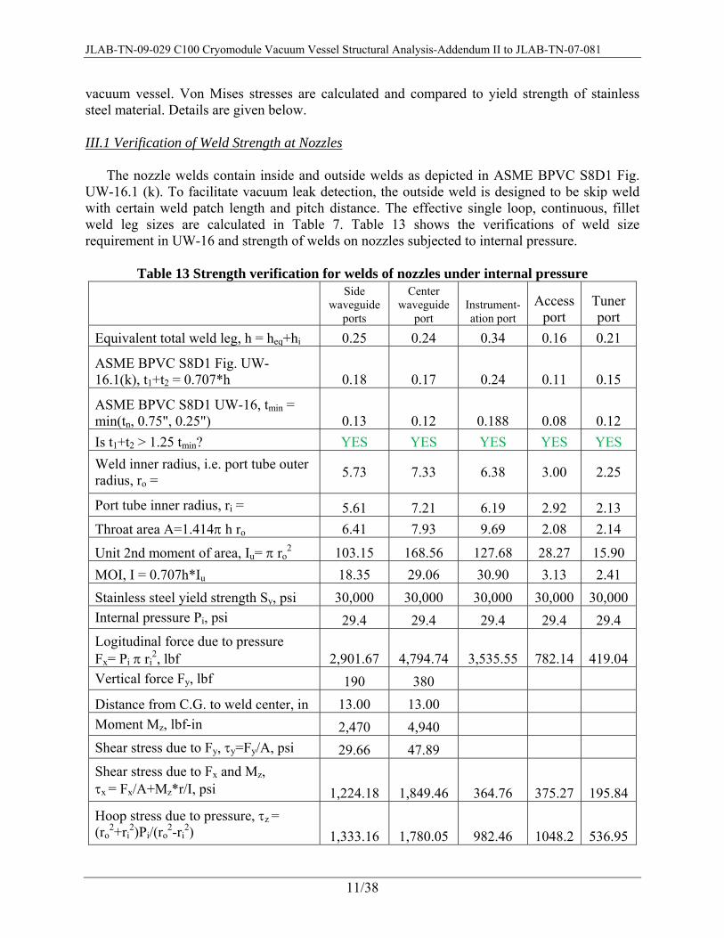
The nozzle welds contain inside and outside welds as depicted in ASME BPVC S8D1 Fig.
UW-16.1 (k). To facilitate vacuum leak detection, the outside weld is designed to be skip weld with certain weld patch length and pitch distance. The effective single loop, continuous, fillet weld leg sizes are calculated in Table 7. Table 13 shows the verifications of weld size requirement in UW-16 and strength of welds on nozzles subjected to internal pressure.
Table 13 Strength verification for welds of nozzles under internal pressure
Side waveguide
ports
Center waveguide
port Instrument-ation port
Access port
Tuner port
Equivalent total weld leg, h = heq+hi 0.25 0.24 0.34 0.16 0.21
ASME BPVC S8D1 Fig. UW-16.1(k), t1+t2 = 0.707*h 0.18 0.17 0.24 0.11 0.15
ASME BPVC S8D1 UW-16, tmin = min(tn, 0.75", 0.25") 0.13 0.12 0.188 0.08 0.12 Is t1+t2 > 1.25 tmin? YES YES YES YES YES Weld inner radius, i.e. port tube outer radius, ro = 5.73 7.33 6.38 3.00 2.25
Port tube inner radius, ri = 5.61 7.21 6.19 2.92 2.13 Throat area A=1.414π h ro 6.41 7.93 9.69 2.08 2.14
Unit 2nd moment of area, Iu= π ro2 103.15 168.56 127.68 28.27 15.90
MOI, I = 0.707h*Iu 18.35 29.06 30.90 3.13 2.41 Stainless steel yield strength Sy, psi 30,000 30,000 30,000 30,000 30,000 Internal pressure Pi, psi 29.4 29.4 29.4 29.4 29.4 Logitudinal force due to pressure Fx= Pi π ri
2, lbf 2,901.67 4,794.74 3,535.55 782.14 419.04 Vertical force Fy, lbf 190 380 Distance from C.G. to weld center, in 13.00 13.00 Moment Mz, lbf-in 2,470 4,940
Shear stress due to Fy, τy=Fy/A, psi 29.66 47.89
Shear stress due to Fx and Mz, τx = Fx/A+Mz*r/I, psi 1,224.18 1,849.46 364.76 375.27 195.84 Hoop stress due to pressure, τz = (ro
2+ri2)Pi/(ro
2-ri2) 1,333.16 1,780.05 982.46 1048.2 536.95

JLAB-TN-09-029 C100 Cryomodule Vacuum Vessel Structural Analysis-Addendum II to JLAB-TN-07-081
12/38
von Mises stress, σ = [3(τx
2+τy2+τy
2)]1/2, psi 3,135.35 4,446.81 1,815.17 1928.3 989.96 Safety factor = Sy / σ 9.57 6.75 16.53 15.56 30.30
Based on Table 13 data, the weld sizes meet requirements set forth in UW-16 and they are
very robust while the nozzles are under internal pressure. Table 14 shows the weld strength verification for the case of external pressure load.
Table 14 Strength verification for welds of nozzles under external pressure
Side
waveguide ports
Center waveguide
port instrument-ation port
Access port
Tuner port
External pressure Po, psi 14.7 14.7 14.7 14.7 14.7 Longitudinal force due to pressure Fx= Po p ro2, lbf 1,516.27 2,477.89 1,876.84 415.63 233.79
Vertical force Fy, lbf 190 380 Distance from C.G. to weld center, inches 13.00 13.00
Moment Mz, lbf-in 2,470 4,940
Shear stress due to Fy, τy=Fy/A, psi 29.66 47.89 Shear stress due to Fx and Mz, τx = Fx/A+Mz*r/I, psi 1,007.90 1,557.47 193.63 199.42 109.26
Hoop stress due to pressure, τz = 2 ro
2 Po/(ro2-ri
2) 681.28 904.72 505.93 538.78 283.18
Von Mises stress, σ = [3(τx
2+τy2+τz
2)]1/2, psi 2,107.76 3,120.83 938.28 995.06 525.72
Safety factor = Sy / σ 14.23 9.61 31.97 30.15 57.06
The welds are found to be safe when nozzles are under external pressure.
III.2 Stiffening Ring Weld Strength Verification There are 6 stiffening rings that are welded to vacuum vessel shell. The welds include an
inside full penetration weld (leveled after welding) and outside skip fillet weld. Skip weld of stiffening ring is permitted in UG-30 (b) and the welding arrangement adopted here is similar to what is described in UG-30(d). The inside and outside skip weld sizes, as well as their equivalent continuous fillet weld sizes, are set as follows (observing rules in UG-30 (d) & (f)): Inside weld leg, hi = 0.25 in. Skip weld leg, ho = 0.25 in. Weld leg h = hi + heq 0.41 in. Skip weld length, Lw = 2.00 in. Weld inner radius r = 15.75 in. Skip weld pitch, p = 3.00 in. Throat area A=1.414π∗h*r 28.97 in2 Vacuum vessel OD = 32.00 in.
JLAB-TN-09-029 C100 Cryomodule Vacuum Vessel Structural Analysis-Addendum II to JLAB-TN-07-081
13/38
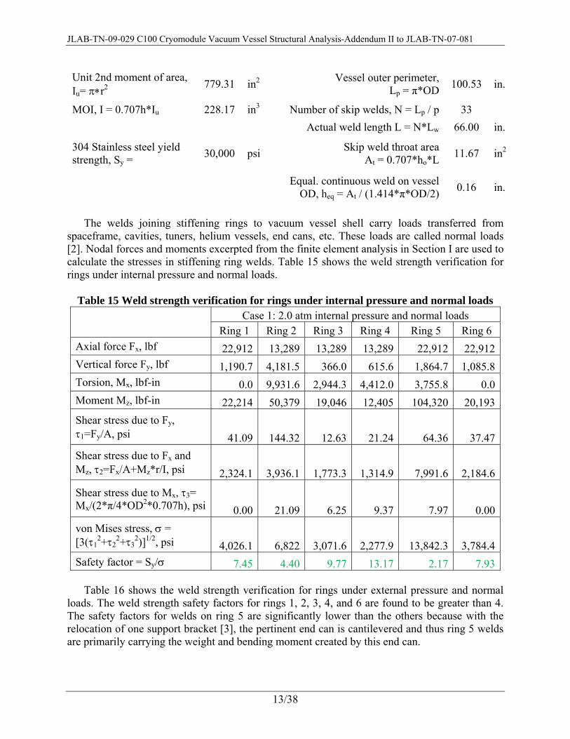
Unit 2nd moment of area, Iu= π∗r2 779.31 in2 Vessel outer perimeter,
Lp = π*OD 100.53 in.
MOI, I = 0.707h*Iu 228.17 in3 Number of skip welds, N = Lp / p 33 Actual weld length L = N*Lw 66.00 in.
304 Stainless steel yield strength, Sy = 30,000 psi Skip weld throat area
At = 0.707*ho*L 11.67 in2
Equal. continuous weld on vessel
OD, heq = At / (1.414*π*OD/2) 0.16 in.
The welds joining stiffening rings to vacuum vessel shell carry loads transferred from
spaceframe, cavities, tuners, helium vessels, end cans, etc. These loads are called normal loads [2]. Nodal forces and moments excerpted from the finite element analysis in Section I are used to calculate the stresses in stiffening ring welds. Table 15 shows the weld strength verification for rings under internal pressure and normal loads.
Table 15 Weld strength verification for rings under internal pressure and normal loads
Case 1: 2.0 atm internal pressure and normal loads Ring 1 Ring 2 Ring 3 Ring 4 Ring 5 Ring 6
Axial force Fx, lbf 22,912 13,289 13,289 13,289 22,912 22,912Vertical force Fy, lbf 1,190.7 4,181.5 366.0 615.6 1,864.7 1,085.8Torsion, Mx, lbf-in 0.0 9,931.6 2,944.3 4,412.0 3,755.8 0.0Moment Mz, lbf-in 22,214 50,379 19,046 12,405 104,320 20,193Shear stress due to Fy, τ1=Fy/A, psi 41.09 144.32 12.63 21.24 64.36 37.47Shear stress due to Fx and Mz, τ2=Fx/A+Mz*r/I, psi 2,324.1 3,936.1 1,773.3 1,314.9 7,991.6 2,184.6
Shear stress due to Mx, τ3= Mx/(2*π/4*OD2*0.707h), psi 0.00 21.09 6.25 9.37 7.97 0.00von Mises stress, σ = [3(τ1
2+τ22+τ3
2)]1/2, psi 4,026.1 6,822 3,071.6 2,277.9 13,842.3 3,784.4Safety factor = Sy/σ 7.45 4.40 9.77 13.17 2.17 7.93
Table 16 shows the weld strength verification for rings under external pressure and normal
loads. The weld strength safety factors for rings 1, 2, 3, 4, and 6 are found to be greater than 4. The safety factors for welds on ring 5 are significantly lower than the others because with the relocation of one support bracket [3], the pertinent end can is cantilevered and thus ring 5 welds are primarily carrying the weight and bending moment created by this end can.
JLAB-TN-09-029 C100 Cryomodule Vacuum Vessel Structural Analysis-Addendum II to JLAB-TN-07-081
14/38
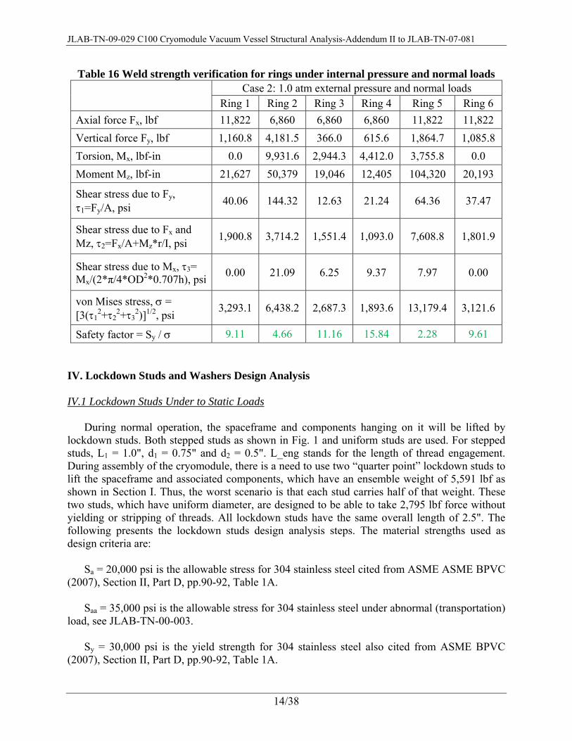
Table 16 Weld strength verification for rings under internal pressure and normal loads Case 2: 1.0 atm external pressure and normal loads
Ring 1 Ring 2 Ring 3 Ring 4 Ring 5 Ring 6 Axial force Fx, lbf 11,822 6,860 6,860 6,860 11,822 11,822 Vertical force Fy, lbf 1,160.8 4,181.5 366.0 615.6 1,864.7 1,085.8 Torsion, Mx, lbf-in 0.0 9,931.6 2,944.3 4,412.0 3,755.8 0.0 Moment Mz, lbf-in 21,627 50,379 19,046 12,405 104,320 20,193
Shear stress due to Fy, τ1=Fy/A, psi 40.06 144.32 12.63 21.24 64.36 37.47
Shear stress due to Fx and Mz, τ2=Fx/A+Mz*r/I, psi 1,900.8 3,714.2 1,551.4 1,093.0 7,608.8 1,801.9
Shear stress due to Mx, τ3= Mx/(2*π/4*OD2*0.707h), psi 0.00 21.09 6.25 9.37 7.97 0.00
von Mises stress, σ = [3(τ1
2+τ22+τ3
2)]1/2, psi 3,293.1 6,438.2 2,687.3 1,893.6 13,179.4 3,121.6
Safety factor = Sy / σ 9.11 4.66 11.16 15.84 2.28 9.61
IV. Lockdown Studs and Washers Design Analysis
IV.1 Lockdown Studs Under to Static Loads
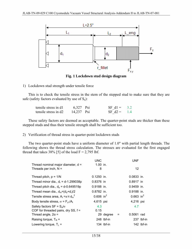
During normal operation, the spaceframe and components hanging on it will be lifted by
lockdown studs. Both stepped studs as shown in Fig. 1 and uniform studs are used. For stepped studs, L1 = 1.0", d1 = 0.75" and d2 = 0.5". L_eng stands for the length of thread engagement. During assembly of the cryomodule, there is a need to use two “quarter point” lockdown studs to lift the spaceframe and associated components, which have an ensemble weight of 5,591 lbf as shown in Section I. Thus, the worst scenario is that each stud carries half of that weight. These two studs, which have uniform diameter, are designed to be able to take 2,795 lbf force without yielding or stripping of threads. All lockdown studs have the same overall length of 2.5". The following presents the lockdown studs design analysis steps. The material strengths used as design criteria are:
Sa = 20,000 psi is the allowable stress for 304 stainless steel cited from ASME ASME BPVC
(2007), Section II, Part D, pp.90-92, Table 1A. Saa = 35,000 psi is the allowable stress for 304 stainless steel under abnormal (transportation)
load, see JLAB-TN-00-003. Sy = 30,000 psi is the yield strength for 304 stainless steel also cited from ASME BPVC
(2007), Section II, Part D, pp.90-92, Table 1A.
JLAB-TN-09-029 C100 Cryomodule Vacuum Vessel Structural Analysis-Addendum II to JLAB-TN-07-081
15/38
Fig. 1 Lockdown stud design diagram
1) Lockdown stud strength under tensile force
This is to check the tensile stress in the stem of the stepped stud to make sure that they are
safe (safety factors evaluated by use of Sa):
tensile stress in d1 6,327 Psi SF_d1 = 3.2 tensile stress in d2 14,237 Psi SF_d2 = 1.4
These safety factors are deemed as acceptable. The quarter-point studs are thicker than these
stepped studs and thus their tensile strength shall be sufficient too.
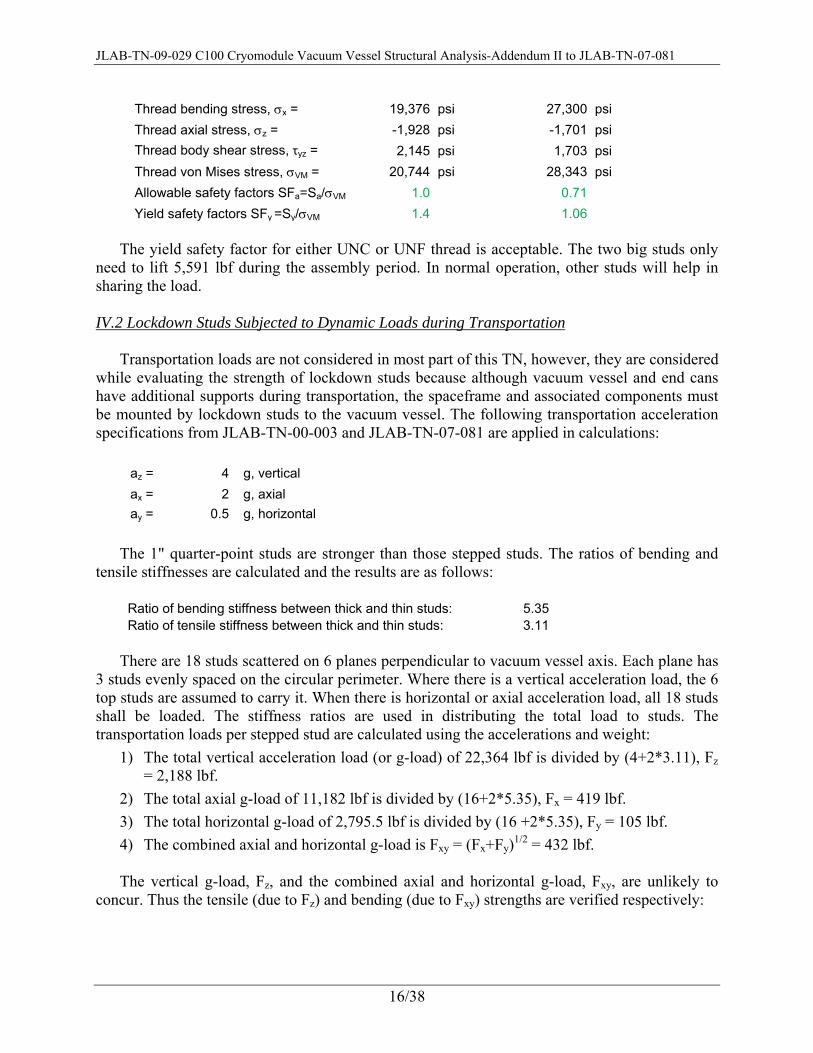
2) Verification of thread stress in quarter-point lockdown studs The two quarter-point studs have a uniform diameter of 1.0" with partial length threads. The
following shows the thread stress calculation. The stresses are evaluated for the first engaged thread that takes 38% [5] of the load F = 2,795 lbf.
UNC UNF
Thread nominal major diameter, d = 1.00 in. Threads per inch, N = 8 12
Thread pitch, p = 1/N 0.1250 in. 0.0833 in. Thread minor dia., dr = d-1.299038p 0.8376 in 0.8917 in Thread pitch dia., dp = d-0.649519p 0.9188 in. 0.9459 in. Thread mean dia., dm=(dp+dr)/2 0.8782 in. 0.9188 in. Tensile stress area, At =π/4 dm
2 0.606 in2 0.663 in2 Body tensile stress, σ = Fz1/At 4,615 psi 4,216 psi Safety factors SF = Sa/σ 4.3 4.7 COF for threaded pairs, dry SS, f = 0.15 Thread angle, 2α = 29 degree = 0.5061 rad Raising torque, TR = 248 lbf-in 237 lbf-in Lowering torque, TL = 134 lbf-in 142 lbf-in
JLAB-TN-09-029 C100 Cryomodule Vacuum Vessel Structural Analysis-Addendum II to JLAB-TN-07-081
16/38
Thread bending stress, σx = 19,376 psi 27,300 psi Thread axial stress, σz = -1,928 psi -1,701 psi Thread body shear stress, τyz = 2,145 psi 1,703 psi Thread von Mises stress, σVM = 20,744 psi 28,343 psi Allowable safety factors SFa=Sa/σVM 1.0 0.71 Yield safety factors SFy =Sy/σVM 1.4 1.06
The yield safety factor for either UNC or UNF thread is acceptable. The two big studs only
need to lift 5,591 lbf during the assembly period. In normal operation, other studs will help in sharing the load.
IV.2 Lockdown Studs Subjected to Dynamic Loads during Transportation
Transportation loads are not considered in most part of this TN, however, they are considered
while evaluating the strength of lockdown studs because although vacuum vessel and end cans have additional supports during transportation, the spaceframe and associated components must be mounted by lockdown studs to the vacuum vessel. The following transportation acceleration specifications from JLAB-TN-00-003 and JLAB-TN-07-081 are applied in calculations:
az = 4 g, vertical ax = 2 g, axial ay = 0.5 g, horizontal
The 1" quarter-point studs are stronger than those stepped studs. The ratios of bending and
tensile stiffnesses are calculated and the results are as follows:
Ratio of bending stiffness between thick and thin studs: 5.35Ratio of tensile stiffness between thick and thin studs: 3.11
There are 18 studs scattered on 6 planes perpendicular to vacuum vessel axis. Each plane has
3 studs evenly spaced on the circular perimeter. Where there is a vertical acceleration load, the 6 top studs are assumed to carry it. When there is horizontal or axial acceleration load, all 18 studs shall be loaded. The stiffness ratios are used in distributing the total load to studs. The transportation loads per stepped stud are calculated using the accelerations and weight:
1) The total vertical acceleration load (or g-load) of 22,364 lbf is divided by (4+2*3.11), Fz = 2,188 lbf.
2) The total axial g-load of 11,182 lbf is divided by (16+2*5.35), Fx = 419 lbf. 3) The total horizontal g-load of 2,795.5 lbf is divided by (16 +2*5.35), Fy = 105 lbf. 4) The combined axial and horizontal g-load is Fxy = (Fx+Fy)1/2 = 432 lbf. The vertical g-load, Fz, and the combined axial and horizontal g-load, Fxy, are unlikely to
concur. Thus the tensile (due to Fz) and bending (due to Fxy) strengths are verified respectively:

JLAB-TN-09-029 C100 Cryomodule Vacuum Vessel Structural Analysis-Addendum II to JLAB-TN-07-081
17/38
d1 = 0.75 in. d2 = 0.5 in. A1 = 0.442 in2 A2 = 0.196 in2 I1 = 0.0155 in4 I2 = 0.00307 in4 c1 = 0.375 in c2 = 0.25 in
σ_z1= 4,952 psi σ_z2= 11,142 psi SF_z1= 7 SF_z2= 3
τ_1= 977 psi τ_2= 2,198 psi
Note that SF_z1 and SF_z2 are tensile stress safety factors in stepped stud sections with diameters of d1 and d2, respectively. They are evaluated using Saa and are found to be sufficient. The following is the evaluation of bending strength for three thread engagement lengths:
L_eng L2 L_arm2 M2 σ_b2 σ2_von
Mises SF2 1.00 0.5 0.875 377.62 30,771 31,006 1.13
0.875 0.625 0.9375 404.60 32,969 33,188 1.05 0.625 0.875 1.0625 458.54 37,365 37,559 0.93
L_arm1 M1 σ_b1 σ1_von Mises SF1
2.00 863.14 20,840 20,908 1.67 2.06 890.11 21,491 21,558 1.62
2.1875 944.06 22,794 22,856 1.53 The design specification for L_eng is 0.875". Based on above results, the safety factors SF1
(in segment with diameter of d1) and SF2 (in segment with diameter of d2) are both acceptable. The 1" studs are thicker than stepped studs and shall be strong enough to withstand all g-loads.
IV.3 Lockdown Studs and Washer Welds Sizing
To be conservative, all transportation loads, namely the Fz and Fxy per stud, are applied while
sizing welds between lockdown studs and washers and between washers and vacuum vessel.
1. Sizing the fillet weld between lockdown stud and washer The cap of lockdown stud is not round. To facilitate the weld sizing calculation, the fillet
weld around stud cap is treated as a circular weld with equivalent throat area, hence, equivalent radius. Details of the weld sizing are presented as follows:
For stepped studs and their washers: Weld size h = 0.19 in. Stud cap perimeter Lp = 7.64 in. Weld equivalent radius, r = Lp/(2π) 1.22 in. Throat area A = h*Lp*0.707 1.03 in2 Primary Shear stress τ1 = Fxy/A 421 psi

JLAB-TN-09-029 C100 Cryomodule Vacuum Vessel Structural Analysis-Addendum II to JLAB-TN-07-081
18/38
Bending moment, M = Fxy*L_arm1 890 lbf-in Unit 2nd MOA, Iu = π*r3 5.64 in3 2nd MOA, I = 0.707*h*Iu 0.76 in4 shear stress due to bending and vertical force, τ2 = M*r/I+Fz/A 3,561 psi total shear, τ = (τ12+τ22)1/2 3,585 psi Safety factor = 0.577*Sy/τ 4.8
For 1" uniform studs and their washers: Weld size h = 0.19 in. Stud cap perimeter Lp = 8.24 in. Weld equivalent radius, r = Lp/(2π) 1.31 in. Throat area A = h*Lp*0.707 1.11 in2 Primary Shear stress τ1 = Fxy/A 390 psi Bending moment, M = Fxy*L_arm1 890 lbf-in Unit 2nd MOA, Iu = π*r3 7.10 in3 2nd MOA, I = 0.707*h*Iu 0.95 in4 shear stress due to bending and vertical force, τ2 = M*r/I+Fz/A 3,200 psi total shear, τ = (τ12+τ22)1/2 3,224 psi Safety factor = 0.577*Sy/τ 5.4
The safety factors are abundant.
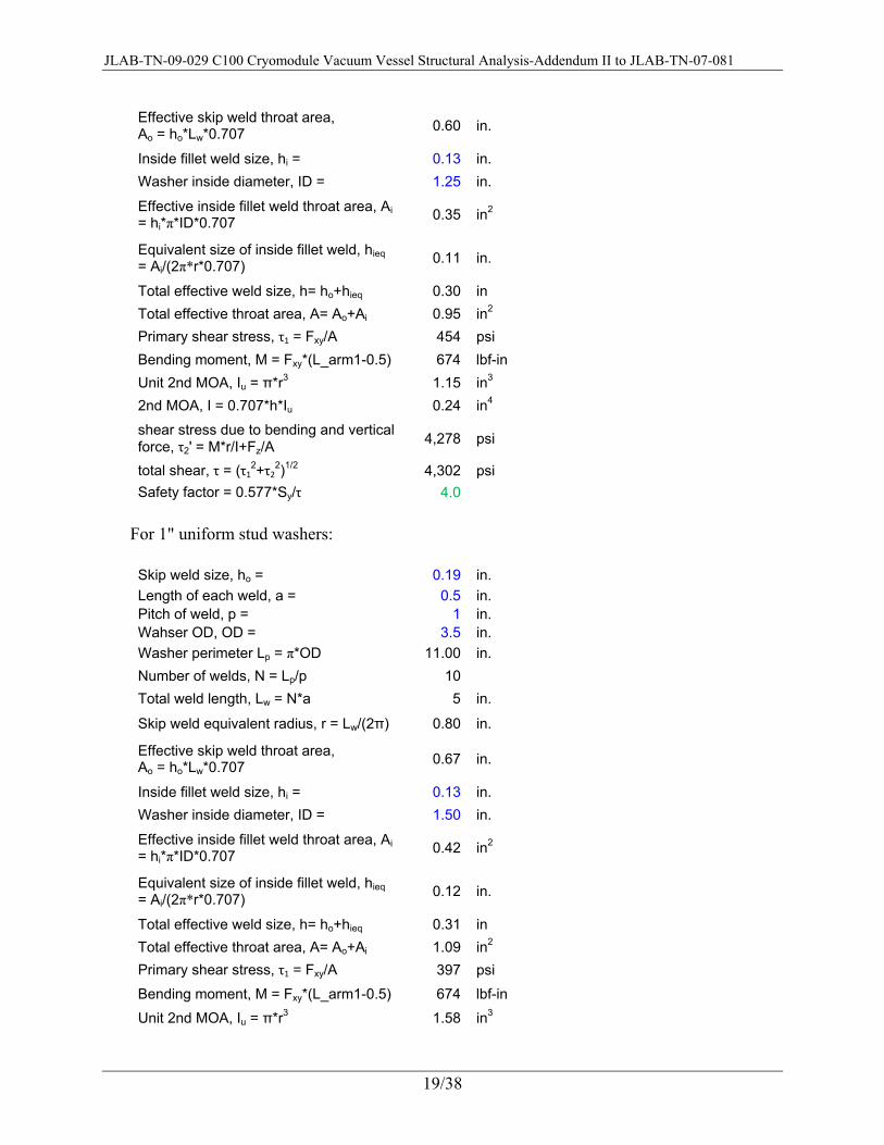
2. Sizing the welds between washer and vacuum vessel There is a sealing fillet weld on the ID of the washer and a skip fillet weld on the OD of the
washer. The two welds are projected to a circular weld with equivalent radius and weld leg size to facilitate the weld sizing calculations. Weld sizing procedure is shown below:
For stepped stud washers: Skip weld size, ho = 0.19 in. Length of each weld, a = 0.5 in. Pitch of weld, p = 1 in. Wahser OD, OD = 3 in. Washer perimeter Lp = π*OD 9.42 in. Number of welds, N = Lp/p 9Total weld length, Lw = N*a 4.5 in. Skip weld equivalent radius, r = Lw/(2π) 0.72 in.
JLAB-TN-09-029 C100 Cryomodule Vacuum Vessel Structural Analysis-Addendum II to JLAB-TN-07-081
19/38
Effective skip weld throat area, Ao = ho*Lw*0.707 0.60 in.
Inside fillet weld size, hi = 0.13 in. Washer inside diameter, ID = 1.25 in.
Effective inside fillet weld throat area, Ai = hi*π*ID*0.707 0.35 in2
Equivalent size of inside fillet weld, hieq = Ai/(2π*r*0.707) 0.11 in.
Total effective weld size, h= ho+hieq 0.30 in Total effective throat area, A= Ao+Ai 0.95 in2 Primary shear stress, τ1 = Fxy/A 454 psi Bending moment, M = Fxy*(L_arm1-0.5) 674 lbf-in Unit 2nd MOA, Iu = π*r3 1.15 in3 2nd MOA, I = 0.707*h*Iu 0.24 in4
shear stress due to bending and vertical force, τ2' = M*r/I+Fz/A 4,278 psi
total shear, τ = (τ12+τ22)1/2 4,302 psi Safety factor = 0.577*Sy/τ 4.0
For 1" uniform stud washers: Skip weld size, ho = 0.19 in. Length of each weld, a = 0.5 in. Pitch of weld, p = 1 in. Wahser OD, OD = 3.5 in. Washer perimeter Lp = π*OD 11.00 in. Number of welds, N = Lp/p 10Total weld length, Lw = N*a 5 in.
Skip weld equivalent radius, r = Lw/(2π) 0.80 in.
Effective skip weld throat area, Ao = ho*Lw*0.707 0.67 in.
Inside fillet weld size, hi = 0.13 in. Washer inside diameter, ID = 1.50 in.
Effective inside fillet weld throat area, Ai = hi*π*ID*0.707 0.42 in2
Equivalent size of inside fillet weld, hieq = Ai/(2π*r*0.707) 0.12 in.
Total effective weld size, h= ho+hieq 0.31 in Total effective throat area, A= Ao+Ai 1.09 in2 Primary shear stress, τ1 = Fxy/A 397 psi Bending moment, M = Fxy*(L_arm1-0.5) 674 lbf-in Unit 2nd MOA, Iu = π*r3 1.58 in3

JLAB-TN-09-029 C100 Cryomodule Vacuum Vessel Structural Analysis-Addendum II to JLAB-TN-07-081
20/38
2nd MOA, I = 0.707*h*Iu 0.34 in4
shear stress due to bending and vertical force, τ2' = M*r/I+Fz/A 3,568 psi
total shear, τ = (τ12+τ22)1/2 3,590 psi Safety factor = 0.577*Sy/τ 4.8
Again, the safety factors are sufficient.
V. Support Bracket Strength Analysis Due to a concern that the long support bracket may cause inconvenience during assembly of
cryomodule, it is broken into short lengths. The segments are flanged and bolted for connection. Figure 2 shows the short stub of support bracket with welded flange. The strength verification of the square tube and welds at root and interface flange are given below. The
Fig. 2 Support bracket with welded flange
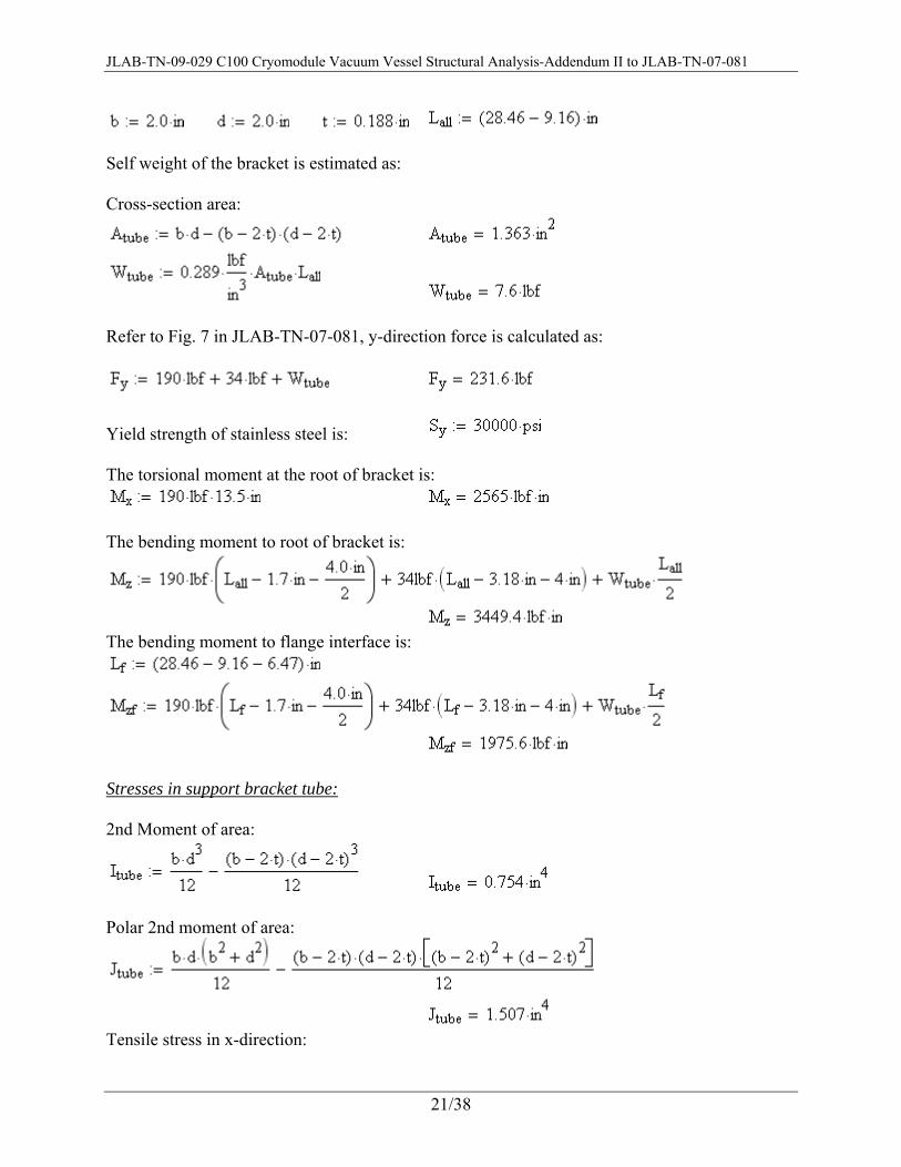
Dimensions of the square tube is (refer to JLAB-TN-09-007 Fig. 8 for dimensions):
JLAB-TN-09-029 C100 Cryomodule Vacuum Vessel Structural Analysis-Addendum II to JLAB-TN-07-081
21/38
Self weight of the bracket is estimated as: Cross-section area:
Refer to Fig. 7 in JLAB-TN-07-081, y-direction force is calculated as:
Yield strength of stainless steel is: The torsional moment at the root of bracket is:
The bending moment to root of bracket is:
The bending moment to flange interface is:
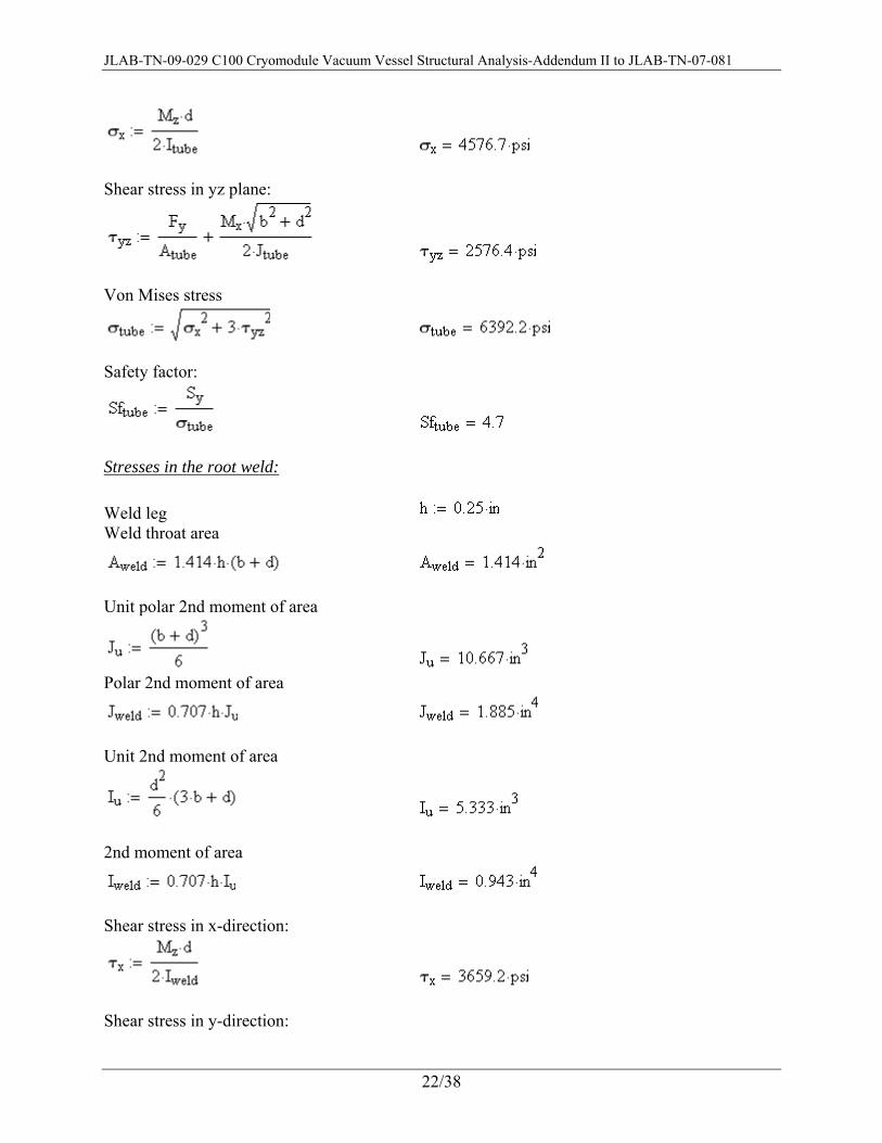
Stresses in support bracket tube: 2nd Moment of area:
Polar 2nd moment of area:
Tensile stress in x-direction:
JLAB-TN-09-029 C100 Cryomodule Vacuum Vessel Structural Analysis-Addendum II to JLAB-TN-07-081
22/38
Shear stress in yz plane:
Von Mises stress
Safety factor:
Stresses in the root weld: Weld leg Weld throat area
Unit polar 2nd moment of area
Polar 2nd moment of area
Unit 2nd moment of area
2nd moment of area
Shear stress in x-direction:
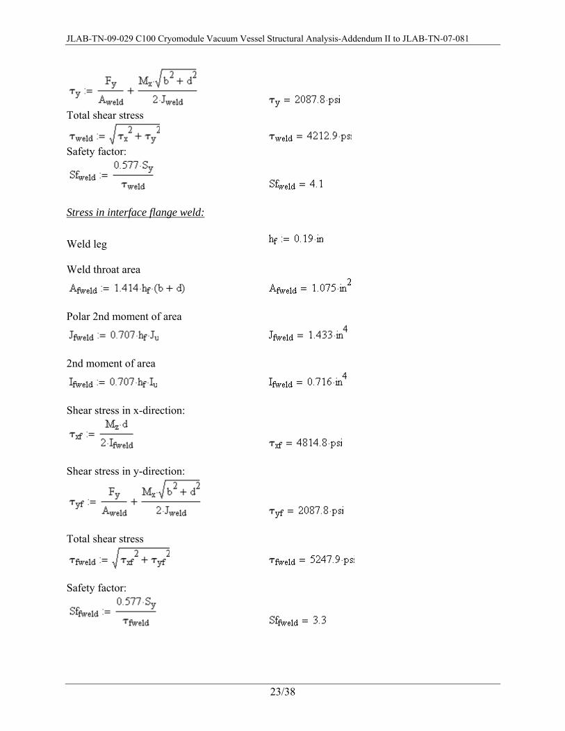
Shear stress in y-direction:
JLAB-TN-09-029 C100 Cryomodule Vacuum Vessel Structural Analysis-Addendum II to JLAB-TN-07-081
23/38
Total shear stress
Safety factor:
Stress in interface flange weld:
Weld leg Weld throat area
Polar 2nd moment of area
2nd moment of area
Shear stress in x-direction:
Shear stress in y-direction:
Total shear stress
Safety factor:

JLAB-TN-09-029 C100 Cryomodule Vacuum Vessel Structural Analysis-Addendum II to JLAB-TN-07-081
24/38
VI. Chronological Summary 1. The JLAB-TN-07-081 addressed the structural design of vacuum vessel on a few aspects:
1) Determination of the minimum required wall thickness of vacuum vessel per ASME BPVC S8D1. All calculations are obsolete because i) the definition of primary membrane and bending stresses in UG-23(c) is unclear, the finite element analyses carried out did not precisely produce such stresses, ii) weights of cryomodule components were estimated on basis of SNS cryomodule components and are inaccurate, iii) UG-16(b) requirement was missed.
2) Stiffening rings required MOI per UG-29: valid but incomplete because one of the vacuum vessel ground support tabs is relocated.
3) All calculations regarding to openings and reinforcements are obsolete because: i) required minimum nozzle wall thickness is governed by UG-16(b) and UG-45, they are not included in JLAB-TN-07-081, ii) welds at all openings have been revised.
4) Stress analysis in spaceframe lockdown studs is obsolete because: i) weights of cryomodule components are updated, ii) the approach to divide transportation loads is changed and vertical acceleration is not combined with the other two accelerations, iii) lifting of spaceframe and associated components with two studs was not considered in design of studs.
5) Support bracket structural analysis is obsolete and was updated in JLAB-TN-09-007.
6) Stiffening ring weld strength verification is obsolete because: i) welds are revised to have full penetration weld inside and skip fillet weld outside, ii) mechanical loads have changed.
2. The JLAB-TN-09-007 updated JLAB-TN-07-081 due to design changes include: i) instrumentation ports are enlarged, ii) support brackets size is reduced, and iii) one vacuum vessel ground support tab is relocated. The following summarizes the status of the analysis in JLAB-TN-09-007:
1) Vacuum vessel stress analysis for determination of required minimum wall thickness is obsolete because: i) the weights of cryomodule components have been updated, ii) primary membrane and bending stress were not clearly defined and evaluated.
2) Stiffening rings required MOI per UG-29: valid. 3) The instrumentation port analysis is obsolete because: i) the welds have been
revised, ii) required nozzle wall thickness calculation needs to consider UG-16(b) and UG-45 requirements.
4) Support bracket analysis is obsolete. 5) Stiffening ring weld strength verification is obsolete because i) welds have been
revised, ii) mechanical loads have been updated.
3. This TN has the latest updates on vacuum vessel structural analysis: i) cryomodule
JLAB-TN-09-029 C100 Cryomodule Vacuum Vessel Structural Analysis-Addendum II to JLAB-TN-07-081
25/38
component weights are updated based on the final design, ii) ASME BPVC S8D1 required minimum wall thickness calculation is revised, iii) welds at all nozzles and stiffening rings are changed and their sizes and strengths are analyzed, iv) lockdown studs and washers are re-designed to allow lifting of spaceframe and associated components with two studs and related welds are sized and verified for structural integrity.
REFERENCES
[1]. 2007 ASME Boiler & Pressure Vessel Code, Section VIII, Division 1, “Rules for Construction of Pressure Vessels”, The American Society of Mechanical Engineers. [2]. G. Cheng and E. F. Daly, “C100 Cryomodule Vacuum Vessel Structural Analysis,” JLAB-TN-07-081, Jefferson Lab, Newport News, VA. [3]. G. Cheng and E. F. Daly, “C100 Cryomodule Vacuum Vessel Structural Analysis-An Addendum to JLAB-TN-07-081,” JLAB-TN-09-007, Jefferson Lab, Newport News, VA. [4]. 2007 ASME Bolier & Pressure Vessel Code, Section II, Part D, “Material Properties (Customary),” The American Society of Mechanical Engineers. [5]. T. P. Pastor and J. Hechmer, “ASME Task Group Report on Primary Stress,” Journal of Pressure Vessel Technology, Vol. 119, February 1997, pp. 61-67. [6]. G. Hollinger and J. Hechmer, “Three-Dimensional Stress Criteria – Summary of the PVRC Project,” Journal of Pressure Vessel Technology, Vol. 122, Feburary 2000, pp. 105-109. [7]. J. E. Shigley, C. R. Mischke, and R. G. Budynas, “Mechanical Engineering Design – 7th Ed,” McGraw-Hill, New York, 2004.

JLAB-TN-09-029 C100 Cryomodule Vacuum Vessel Structural Analysis-Addendum II to JLAB-TN-07-081
26/38
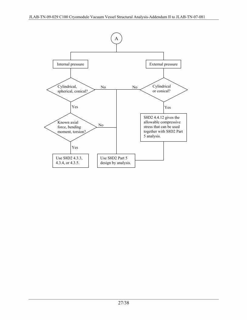
Appendix 1 Analyze Pressure Vessel by ASME BPVC Division 1 or 2
The question of using Division 1 or Division 2 rules arose during the vacuum vessel BPVC analysis when UG-23(c) fails to give a clear definition of primary membrane and bending stresses. In general, when Division 1 rules are difficult or impossible to apply, Division 2 rules are the alternative. A comprehensive discussion of when to use Division 2 rules can be lengthy and is not within the scope of this appendix. Rather, the specific topic of determining the required minimum shell thickness, which was needed in vacuum vessel BPVC analysis, is investigated to show how relevant S8D1 or S8D2 rules may be applied. The following flow diagram shows the options. Please note that the referenced S8D2 parts give not just formulas for the required thickness and in principle, S8D2 part 5 is always applicable no matter what geometry or loading condition that the under study pressure vessel has.
Determine pressure vessel required shell thickness
Internal pressure External pressure
Pressure load only?
Use S8D1 UG-27 or S8D2 4.3.3, 4.3.5
S8D2 4.3.4
S8D2 Part 5 design by analysis
S8D2 4.4.6
Use S8D1 UG-28 or S8D2 4.4.5, 4.4.7
A
No
Yes
Yes Yes
Yes Yes
No
No No
No Conical?
Cylindrical or spherical?
Cylindrical or spherical?
Conical?
S8D2 Part 5 design by analysis
JLAB-TN-09-029 C100 Cryomodule Vacuum Vessel Structural Analysis-Addendum II to JLAB-TN-07-081
27/38
A
Internal pressure External pressure
Cylindrical or conical?
Use S8D2 4.3.3, 4.3.4, or 4.3.5.
S8D2 4.4.12 gives the allowable compressive stress that can be used together with S8D2 Part 5 analysis.
Use S8D2 Part 5 design by analysis.
Cylindrical, spherical, conical?
Known axial force, bending moment, torsion?
Yes
Yes
Yes
No No
No
JLAB-TN-09-029 C100 Cryomodule Vacuum Vessel Structural Analysis-Addendum II to JLAB-TN-07-081
28/38
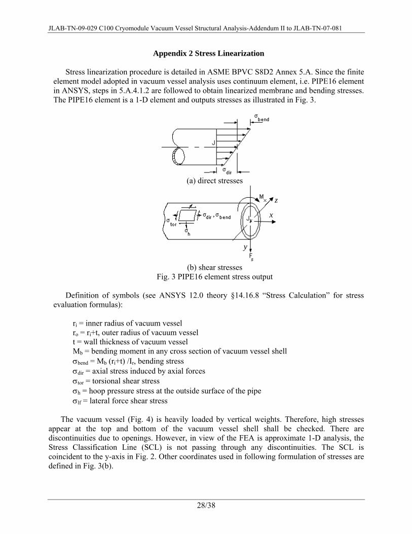
Appendix 2 Stress Linearization Stress linearization procedure is detailed in ASME BPVC S8D2 Annex 5.A. Since the finite
element model adopted in vacuum vessel analysis uses continuum element, i.e. PIPE16 element in ANSYS, steps in 5.A.4.1.2 are followed to obtain linearized membrane and bending stresses. The PIPE16 element is a 1-D element and outputs stresses as illustrated in Fig. 3.
(a) direct stresses
(b) shear stresses
Fig. 3 PIPE16 element stress output Definition of symbols (see ANSYS 12.0 theory §14.16.8 “Stress Calculation” for stress
evaluation formulas):
ri = inner radius of vacuum vessel ro = ri+t, outer radius of vacuum vessel t = wall thickness of vacuum vessel Mb = bending moment in any cross section of vacuum vessel shell σbend = Mb (ri+t) /Ir, bending stress σdir = axial stress induced by axial forces σtor = torsional shear stress σh = hoop pressure stress at the outside surface of the pipe σlf = lateral force shear stress
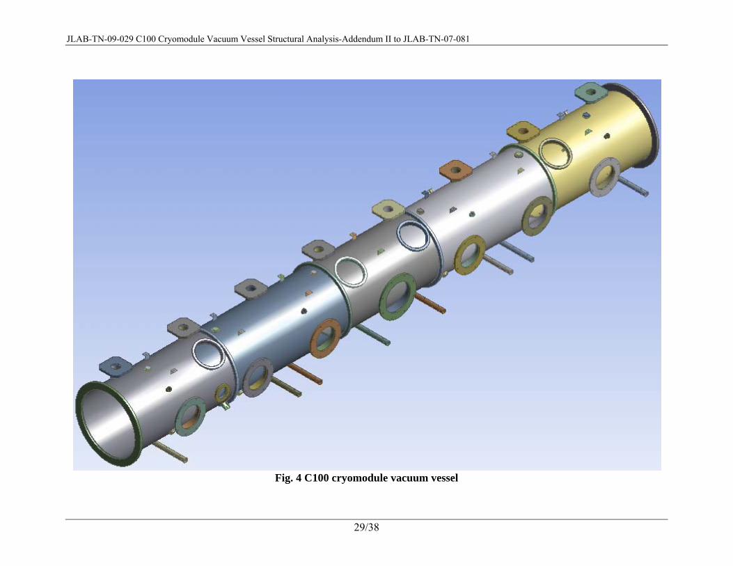
The vacuum vessel (Fig. 4) is heavily loaded by vertical weights. Therefore, high stresses appear at the top and bottom of the vacuum vessel shell shall be checked. There are discontinuities due to openings. However, in view of the FEA is approximate 1-D analysis, the Stress Classification Line (SCL) is not passing through any discontinuities. The SCL is coincident to the y-axis in Fig. 2. Other coordinates used in following formulation of stresses are defined in Fig. 3(b).
x
y
z
JLAB-TN-09-029 C100 Cryomodule Vacuum Vessel Structural Analysis-Addendum II to JLAB-TN-07-081
29/38
Fig. 4 C100 cryomodule vacuum vessel

JLAB-TN-09-029 C100 Cryomodule Vacuum Vessel Structural Analysis-Addendum II to JLAB-TN-07-081
30/38
Stress integration method is adopted. Among all stress components, the stress induced by bending moment Mb varies across thickness. The vacuum vessel is a thin wall pressure vessel so that hope stress and longitudinal stress are nearly constant across thickness. The radial stress due to pressure can be neglected. Here, a compressive pressure equal to either internal or external pressure is used as radial stress to be conservative. The transverse shear stress, σlf = 2 Fs/A, reported by ANSYS is actually the maximum shear stress in an annulus cross section. And the shear stress caused by torsion, i.e. σtor, does not vary so much through thickness.
Refer to ASME BPVC S8D2, Annex 5.A, paragraph 5.A.4.1.2, the steps are:
STEP 1: Calculate the membrane stress: as explained above, the bending stress component is
the only one to be averaged across thickness.
( )⎟⎠⎞
⎜⎝⎛ +=
+= ∫ 2
10
trI
Mdx
IxrM
t ir
bt
r
ibmσ
Notice that bendi
i
m tr
trσσ
+
+= 2
STEP 2: Calculate the bending stress: hoops stress is nearly invariant across the thickness, so
only the bending stress is considered.
( )tr
tdxxtxrI
Mt i
bendt
ir
bb +
−=⎟⎠⎞
⎜⎝⎛ −+= ∫ 22
602
σσ
For the vacuum vessel that has design inner radius of 15.75" and shell thickness of t = 0.25",
the σb = 0.78% σbend, which is quite small. This would explain why there is little difference between the Pm and Pb+Pm in Tables 1 and 2.
STEP 3: Peak stress calculation is not required in S8D1 UG-23(c), the stress intensity = 1st
principal stress – 3rd principal stress is actually used. STEP 4: Calculate the principal stresses. This is done by use of Cardano’s formula. First, let’s take a look at the stress components at the top and bottom of shell. Top of Shell: Membrane stresses:
bendi
idirmx tr
trσσσ
++
+=2/
, , σy,m = -p, σz,m = σh
τxz,m = σtor, τxy,m = -σlf

JLAB-TN-09-029 C100 Cryomodule Vacuum Vessel Structural Analysis-Addendum II to JLAB-TN-07-081
31/38
Figure 5 illustrates the direction of shear stresses on the top of vacuum vessel shell. Bending stresses:
trt
ibendbx +
= σσ21
, , σy,b = 0, σz,b = 0,
τxy,b=0, τxz,b = 0 Membrane plus bending stresses:
benddirbxmxmbx σσσσσ +=+= ,,, , σy,mb = -p, σz,mb = σh τxy,mb = σtor, τxz,mb = -σlf
Fig. 5 Finite volume for illustration of shear stresses at top of shell
Bottom of Shell: Membrane stresses:
bendi
idirmx tr
trσσσ
++
−=2/
, , σy,m = -p, σz,m = σh
τxz,m = -σtor, τxy,m = -σlf The shear stress caused by torsion, changes direction from the top of shell to bottom of shell. Bending stresses:
trt
ibendbx +
−= σσ21
, , σy,b = 0, σz,b = 0,
τxy,b=0, τxz,b = 0 Membrane plus bending stresses:
y
x
z τxz
τxy

JLAB-TN-09-029 C100 Cryomodule Vacuum Vessel Structural Analysis-Addendum II to JLAB-TN-07-081
32/38
benddirbxmxmbx σσσσσ −=+= ,,, , σy,mb = -p, σz,mb = σh τxy,mb = -σtor, τxz,mb = -σlf Given the stress components, the principal stresses are the roots of a cubic order
characteristic equation: σ3 - I1σ2 + I2σ - I3 = 0 Where, the stress invariants, I1, I2, and I3 are defined as follows (using membrane stress
components as example):
mzmymxI ,,,1 σσσ ++= 2
,2
,,,,,,,2 mxzmxymzmxmzmymymxI ττσσσσσσ −−++= 2
,,2
,,,,,3 mxymzmxzmymzmymxI τστσσσσ −−= Observing Cardano’s formula, the following parameters are defined:
93 2
12 IIQ −= 54
2279 31321 IIII
R++−
= D = Q3+R2 ⎟⎟
⎠
⎞
⎜⎜
⎝
⎛
−= −
3
1cosQ
Rθ
When D<0, which shall be the case for stress analysis, there are three real roots:
33cos2 1
1I
Qroot +⎟⎠⎞
⎜⎝⎛−=θσ
332cos2 1
2IQroot +⎟
⎠⎞
⎜⎝⎛ +
−=πθσ
334cos2 1
3I
Qroot +⎟⎠⎞
⎜⎝⎛ +
−=πθσ
Note that the above three roots need to be sorted to determine the 1st, 2nd, and 3rd principal
stresses. STEP 5: Calculate the equivalent stress use Eq. (2). The above steps are coded in an ANSYS Parametric Design Language (APDL) input
command file to post-process the stress results from vacuum vessel FEA for different loading cases.
JLAB-TN-09-029 C100 Cryomodule Vacuum Vessel Structural Analysis-Addendum II to JLAB-TN-07-081
33/38
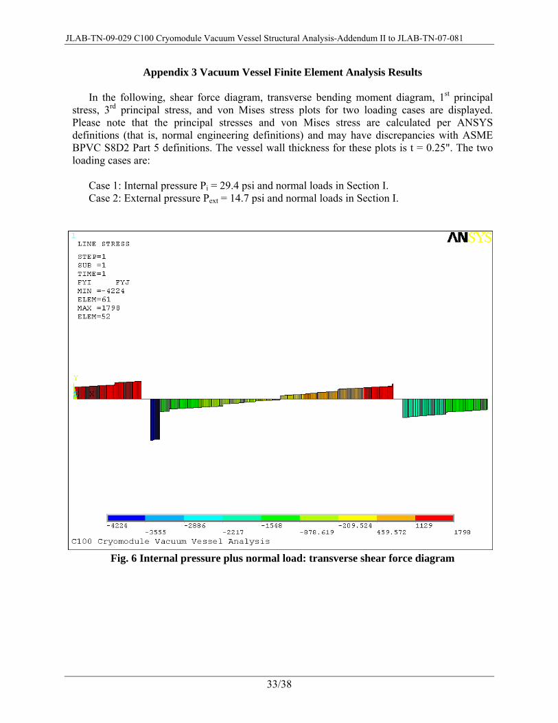
Appendix 3 Vacuum Vessel Finite Element Analysis Results
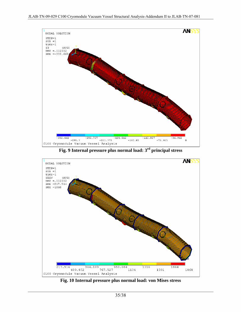
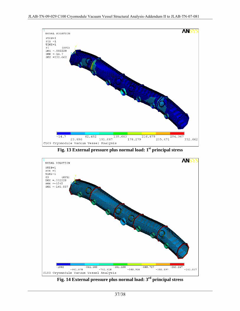
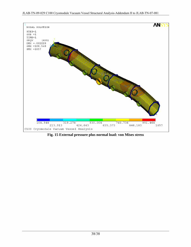
In the following, shear force diagram, transverse bending moment diagram, 1st principal stress, 3rd principal stress, and von Mises stress plots for two loading cases are displayed. Please note that the principal stresses and von Mises stress are calculated per ANSYS definitions (that is, normal engineering definitions) and may have discrepancies with ASME BPVC S8D2 Part 5 definitions. The vessel wall thickness for these plots is t = 0.25". The two loading cases are:
Case 1: Internal pressure Pi = 29.4 psi and normal loads in Section I. Case 2: External pressure Pext = 14.7 psi and normal loads in Section I.
Fig. 6 Internal pressure plus normal load: transverse shear force diagram
JLAB-TN-09-029 C100 Cryomodule Vacuum Vessel Structural Analysis-Addendum II to JLAB-TN-07-081
34/38
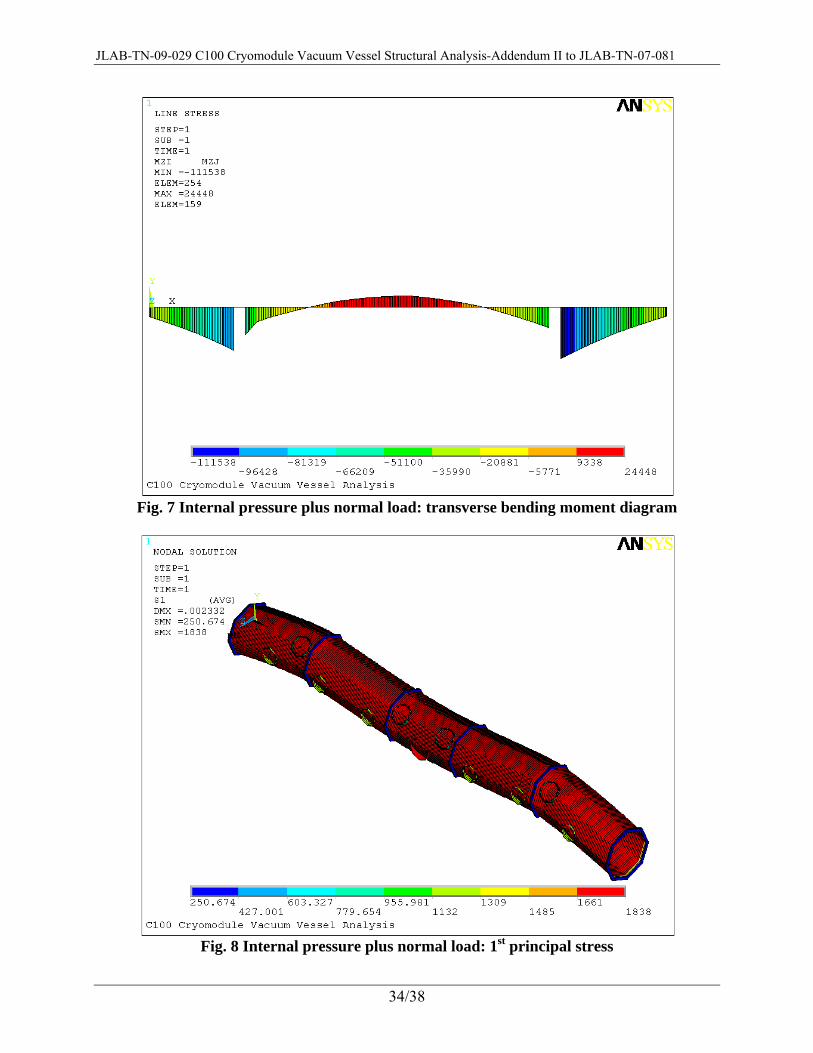
Fig. 7 Internal pressure plus normal load: transverse bending moment diagram
Fig. 8 Internal pressure plus normal load: 1st principal stress
JLAB-TN-09-029 C100 Cryomodule Vacuum Vessel Structural Analysis-Addendum II to JLAB-TN-07-081
35/38
Fig. 9 Internal pressure plus normal load: 3rd principal stress
Fig. 10 Internal pressure plus normal load: von Mises stress

JLAB-TN-09-029 C100 Cryomodule Vacuum Vessel Structural Analysis-Addendum II to JLAB-TN-07-081
36/38
Fig. 11 External pressure plus normal load: transverse shear force diagram
Fig. 12 External pressure plus normal load: transverse bending moment diagram
JLAB-TN-09-029 C100 Cryomodule Vacuum Vessel Structural Analysis-Addendum II to JLAB-TN-07-081
37/38
Fig. 13 External pressure plus normal load: 1st principal stress
Fig. 14 External pressure plus normal load: 3rd principal stress
JLAB-TN-09-029 C100 Cryomodule Vacuum Vessel Structural Analysis-Addendum II to JLAB-TN-07-081
38/38
Fig. 15 External pressure plus normal load: von Mises stress


![C100 Cryomodule End Can Pipeline Design per ASME B31tnweb.jlab.org/tn/2009/09-002.doc · Web viewRules in ASME B&PV code [2] Section VIII “Rules for Construction of Pressure Vessels”](https://img.pdfslide.us/doc/110x75/5ac0817e7f8b9aca388bfb16/c100-cryomodule-end-can-pipeline-design-per-asme-viewrules-in-asme-bpv-code-2.jpg)