Embed Size (px)
Citation preview

AT-1
AUTOMATIC TRANSAXLE
C TRANSMISSION/TRANSAXLE
CONTENTS
D
E
F
G
H
I
J
K
L
M
SECTION
A
B
AT
Revision: July 2005 2005 Maxima
INDEX FOR DTC ........................................................ 5Alphabetical Index .................................................... 5DTC No. Index ......................................................... 6
PRECAUTIONS .......................................................... 7Precautions for Supplemental Restraint System (SRS) “AIR BAG” and “SEAT BELT PRE-TEN-SIONER” .................................................................. 7Precautions for On Board Diagnostic (OBD) System of A/T and Engine .................................................... 7Precautions for A/T Assembly or TCM Replacement ..... 8Precautions .............................................................. 9Service Notice or Precautions .................................11Wiring Diagrams and Trouble Diagnosis .................11
PREPARATION ......................................................... 12Special Service Tools ............................................. 12Commercial Service Tools ...................................... 14
A/T FLUID ................................................................. 15Changing A/T Fluid ................................................ 15Checking A/T Fluid ................................................. 15
A/T CONTROL SYSTEM .......................................... 16Cross-Sectional View ............................................. 16Shift Mechanism ..................................................... 17TCM Function ......................................................... 34Input/Output Signal of TCM .................................... 35CAN Communication .............................................. 35Line Pressure Control ............................................ 36Shift Control ........................................................... 36Lock-Up Control ..................................................... 38
ON BOARD DIAGNOSTIC (OBD) SYSTEM ............ 40Introduction ............................................................ 40OBD-II Function for A/T System ............................. 40One or Two Trip Detection Logic of OBD-II ............ 40OBD-II Diagnostic Trouble Code (DTC) ................. 40Malfunction Indicator Lamp (MIL) ........................... 43
TROUBLE DIAGNOSIS ............................................ 44DTC Inspection Priority Chart ................................ 44Fail-Safe ................................................................. 44How To Perform Trouble Diagnosis For Quick and Accurate Repair ..................................................... 47A/T Electrical Parts Location .................................. 52
Circuit Diagram ....................................................... 53Inspections Before Trouble Diagnosis .................... 54Check Before Engine is Started .............................. 58Check at Idle ........................................................... 58Cruise Test - Part 1 ................................................. 60Cruise Test - Part 2 ................................................. 61Cruise Test - Part 3 ................................................. 62Shift Schedule ........................................................ 63Symptom Chart ....................................................... 64TCM Input/Output Signal Reference Values ........... 71CONSULT-II Function (TCM) .................................. 74Diagnostic Procedure Without CONSULT-II ........... 80
DTC U1000 CAN COMMUNICATION LINE .............. 83Description .............................................................. 83On Board Diagnosis Logic ...................................... 83Possible Cause ....................................................... 83DTC Confirmation Procedure ................................. 83Wiring Diagram — AT — CAN ................................ 84Diagnostic Procedure ............................................. 85
DTC P0500 VEHICLE SPEED SENSOR MTR ......... 86Description .............................................................. 86On Board Diagnosis Logic ...................................... 86Possible Cause ....................................................... 86DTC Confirmation Procedure ................................. 86Diagnostic Procedure ............................................. 87
DTC P0613 TCM PROCESSOR ............................... 88Description .............................................................. 88On Board Diagnosis Logic ...................................... 88Possible Cause ....................................................... 88DTC Confirmation Procedure ................................. 88Diagnostic Procedure ............................................. 89
DTC P0705 PARK/NEUTRAL POSITION SWITCH ... 90Description .............................................................. 90On Board Diagnosis Logic ...................................... 90Possible Cause ....................................................... 90DTC Confirmation Procedure ................................. 90Wiring Diagram — AT — PNP/SW ......................... 91Diagnostic Procedure ............................................. 92Component Inspection ............................................ 94
DTC P0710 A/T FLUID TEMPERATURE SENSOR

AT-2Revision: July 2005 2005 Maxima
CIRCUIT .................................................................... 95Description .............................................................. 95On Board Diagnosis Logic ...................................... 95Possible Cause ....................................................... 95DTC Confirmation Procedure ................................. 95Wiring Diagram — AT — FTS ................................. 96Diagnostic Procedure ............................................. 97Component Inspection ............................................ 99
DTC P0711 FLUID TEMPERATURE SENSOR PER-FORMANCE ............................................................ 100
Description ............................................................ 100On Board Diagnosis Logic .................................... 100Possible Cause ..................................................... 100DTC Confirmation Procedure ............................... 100Wiring Diagram — AT — FTSP ............................ 101Diagnostic Procedure ........................................... 102Component Inspection .......................................... 104
DTC P0717 TURBINE REVOLUTION SENSOR CIR-CUIT ........................................................................ 105
Description ............................................................ 105On Board Diagnosis Logic .................................... 105Possible Cause ..................................................... 105DTC Confirmation Procedure ............................... 105Wiring Diagram — AT — TRSC ............................ 106Diagnostic Procedure ........................................... 107Component Inspection .......................................... 108
DTC P0722 VEHICLE SPEED SENSOR A/T (REV-OLUTION SENSOR) CIRCUIT ................................ 109
Description ............................................................ 109On Board Diagnosis Logic .................................... 109Possible Cause ..................................................... 109DTC Confirmation Procedure ............................... 109Wiring Diagram — AT — VSSATC ....................... 110Diagnostic Procedure ............................................111Component Inspection .......................................... 112
DTC P0726 ENGINE SPEED INPUT CIRCUIT PER-FORMANCE ............................................................ 113
Description ............................................................ 113On Board Diagnosis Logic .................................... 113Possible Cause ..................................................... 113DTC Confirmation Procedure ............................... 113Diagnostic Procedure ........................................... 113
DTC P0731 A/T 1ST GEAR FUNCTION ................. 115Description ............................................................ 115On Board Diagnosis Logic .................................... 115Possible Cause ..................................................... 115DTC Confirmation Procedure ............................... 115Wiring Diagram — AT — 1STSIG ......................... 116Diagnostic Procedure ........................................... 117
DTC P0732 A/T 2ND GEAR FUNCTION ................ 118Description ............................................................ 118On Board Diagnosis Logic .................................... 118Possible Cause ..................................................... 118DTC Confirmation Procedure ............................... 118Wiring Diagram — AT — 2NDSIG ........................ 120Diagnostic Procedure ........................................... 122
DTC P0733 A/T 3RD GEAR FUNCTION ................ 124Description ............................................................ 124On Board Diagnosis Logic .................................... 124
Possible Cause .....................................................124DTC Confirmation Procedure ................................124Wiring Diagram — AT — 3RDSIG ........................126Diagnostic Procedure ............................................128
DTC P0734 A/T 4TH GEAR FUNCTION .................130Description ............................................................130On Board Diagnosis Logic ....................................130Possible Cause .....................................................130DTC Confirmation Procedure ................................130Wiring Diagram — AT — 4THSIG .........................132Diagnostic Procedure ............................................133
DTC P0735 A/T 5TH GEAR FUNCTION .................135Description ............................................................135On Board Diagnosis Logic ....................................135Possible Cause .....................................................135DTC Confirmation Procedure ................................135Wiring Diagram — AT — 5THSIG .........................137Diagnostic Procedure ............................................139
DTC P0744 A/T TCC S/V FUNCTION (LOCK-UP) .141Description ............................................................141On Board Diagnosis Logic ....................................141Possible Cause .....................................................141DTC Confirmation Procedure ................................141Wiring Diagram — AT — TCCSIG ........................142Diagnostic Procedure ............................................143
DTC P0745 PRESSURE CONTROL SOLENOID VALVE A (LINE PRESSURE) ..................................144
Description ............................................................144On Board Diagnosis Logic ....................................144Possible Cause .....................................................144DTC Confirmation Procedure ................................144Wiring Diagram — AT — PC/A .............................145Diagnostic Procedure ............................................146Component Inspection ..........................................148
DTC P0750 SHIFT SOLENOID VALVE A ...............149Description ............................................................149On Board Diagnosis Logic ....................................149Possible Cause .....................................................149DTC Confirmation Procedure ................................149Wiring Diagram — AT — SSV/A ...........................150Diagnostic Procedure ............................................151Component Inspection ..........................................153
DTC P0755 SHIFT SOLENOID VALVE B ...............154Description ............................................................154On Board Diagnosis Logic ....................................154Possible Cause .....................................................154DTC Confirmation Procedure ................................154Wiring Diagram — AT — SSV/B ...........................155Diagnostic Procedure ............................................156Component Inspection ..........................................158
DTC P0760 SHIFT SOLENOID VALVE C ...............159Description ............................................................159On Board Diagnosis Logic ....................................159Possible Cause .....................................................159DTC Confirmation Procedure ................................159Wiring Diagram — AT — SSV/C ...........................160Diagnostic Procedure ............................................161Component Inspection ..........................................163
DTC P0762 SHIFT SOLENOID VALVE C STUCK ON .164

AT-3
D
E
F
G
H
I
J
K
L
M
A
B
AT
Revision: July 2005 2005 Maxima
Description ........................................................... 164On Board Diagnosis Logic ................................... 164Possible Cause .................................................... 164DTC Confirmation Procedure ............................... 164Wiring Diagram — AT — SSV/CS ........................ 165Diagnostic Procedure ........................................... 166Component Inspection ......................................... 168
DTC P0765 SHIFT SOLENOID VALVE D .............. 169Description ........................................................... 169On Board Diagnosis Logic ................................... 169Possible Cause .................................................... 169DTC Confirmation Procedure ............................... 169Wiring Diagram — AT — SSV/D .......................... 170Diagnostic Procedure ........................................... 171Component Inspection ......................................... 173
DTC P0770 SHIFT SOLENOID VALVE E .............. 174Description ........................................................... 174On Board Diagnosis Logic ................................... 174Possible Cause .................................................... 174DTC Confirmation Procedure ............................... 174Wiring Diagram — AT — SSV/E .......................... 175Diagnostic Procedure ........................................... 176Component Inspection ......................................... 178
DTC P0775 PRESSURE CONTROL SOLENOID VALVE B (SHIFT PRESSURE) ............................... 179
Description ........................................................... 179On Board Diagnosis Logic ................................... 179Possible Cause .................................................... 179DTC Confirmation Procedure ............................... 179Wiring Diagram — AT — PC/B ............................. 180Diagnostic Procedure ........................................... 181Component Inspection ......................................... 183
DTC P0780 SHIFT .................................................. 184Description ........................................................... 184On Board Diagnosis Logic ................................... 184Possible Cause .................................................... 184DTC Confirmation Procedure ............................... 184Wiring Diagram — AT — SFTFNC ....................... 185Diagnostic Procedure ........................................... 187
DTC P0795 PRESSURE CONTROL SOLENOID VALVE C (TCC AND SHIFT PRESSURE) ............. 188
Description ........................................................... 188On Board Diagnosis Logic ................................... 188Possible Cause .................................................... 188DTC Confirmation Procedure ............................... 188Wiring Diagram — AT — PC/C ............................ 189Diagnostic Procedure ........................................... 190Component Inspection ......................................... 192
DTC P0797 PRESSURE CONTROL SOLENOID VALVE C STUCK ON ............................................. 193
Description ........................................................... 193On Board Diagnosis Logic ................................... 193Possible Cause .................................................... 193DTC Confirmation Procedure ............................... 193Wiring Diagram — AT — PC/CS .......................... 194Diagnostic Procedure ........................................... 195Component Inspection ......................................... 197
DTC P0826 MANUAL MODE SWITCH CIRCUIT .. 198Description ........................................................... 198
CONSULT-II Reference Value in Data Monitor Mode . 198
On Board Diagnosis Logic .................................... 198Possible Cause ..................................................... 198DTC Confirmation Procedure ............................... 198Wiring Diagram — AT — MMSW ......................... 199Diagnostic Procedure ........................................... 201Component Inspection .......................................... 203Position Indicator .................................................. 203
DTC P0882 TCM POWER INPUT SIGNAL ............ 204Description ............................................................ 204On Board Diagnosis Logic .................................... 204Possible Cause ..................................................... 204DTC Confirmation Procedure ............................... 204Wiring Diagram — AT — PWR/IN ........................ 205Diagnostic Procedure ........................................... 207Component Inspection .......................................... 208
DTC P1726 ELECTRIC THROTTLE CONTROL SYSTEM .................................................................. 209
Description ............................................................ 209TROUBLE DIAGNOSIS FOR SYMPTOMS ............ 210
A/T CHECK Indicator Lamp does not come on .... 210Engine Cannot Be Started In “P” or “N” Position .. 212In “P” Position, Vehicle Moves When Pushed ...... 212In “N” Position, Vehicle Moves .............................. 213Large Shock (“N” to “D” Position) ......................... 214Vehicle Does Not Creep Backward In “R” Position . 215Vehicle Does Not Creep Forward In “D” Position . 216Vehicle Cannot Be Started From D1 ..................... 217A/T Does Not Shift: D1 → D2 ................................ 217A/T Does Not Shift: D2 → D3 ................................ 218A/T Does Not Shift: D3 → D4 ................................ 219A/T Does Not Shift: D4 → D5 ................................ 220A/T Does Not Perform Lock-up ............................ 221A/T Does Not Hold Lock-up Condition .................. 222Lock-up Is Not Released ...................................... 223Cannot Be Changed to Manual Mode .................. 224A/T Does Not Shift: 5th gear → 4th gear .............. 225A/T Does Not Shift: 4th gear → 3rd gear .............. 226A/T Does Not Shift: 3rd gear → 2nd gear ............. 226A/T Does Not Shift: 2nd gear → 1st gear ............. 227Vehicle Does Not Decelerate By Engine Brake .... 228TCM Self-diagnosis Does Not Activate ................ 229
SHIFT CONTROL SYSTEM .................................... 231Control Device ...................................................... 231Control Cable ........................................................ 232
A/T SHIFT LOCK SYSTEM .................................... 233Description ............................................................ 233Shift Lock System Electrical Parts Location ......... 233Wiring Diagram — AT — SHIFT ........................... 234Shift Lock Control Unit Reference Values ............ 235Component Inspection .......................................... 236
ON-VEHICLE SERVICE .......................................... 238Revolution Sensor Replacement .......................... 238Turbine Revolution Sensor Replacement ............. 238Park/Neutral Position (PNP) Switch Adjustment .. 238ATF Cooler ........................................................... 239ATF Cooler Valve .................................................. 239Control Cable Adjustment ..................................... 240

AT-4Revision: July 2005 2005 Maxima
Side cover ............................................................. 241Control Valve Assembly ........................................ 241Terminal cord assembly ........................................ 241
TRANSAXLE ASSEMBLY ...................................... 243Removal and Installation ...................................... 243INSPECTION AFTER REMOVAL ......................... 243
OVERHAUL ............................................................. 245Components ......................................................... 245Locations of Needle Bearings, Bearing Races and Thrust Washers .................................................... 251
DISASSEMBLY ....................................................... 252Disassembly ......................................................... 252
REPAIR FOR COMPONENT PARTS ...................... 272Oil Pump, 2nd Coast Brake & 2nd Brake ............. 272One-Way Clutch Outer Race Sub Assembly & 2nd Coast Brake Hub & One-Way Clutch No.1 ........... 278Transaxle Case Cover & B5 Brake ....................... 280Differential Gear Assembly ................................... 285
ASSEMBLY .............................................................288Assembly (1) .........................................................288Adjustment ............................................................295Assembly (2) .........................................................296
SERVICE DATA AND SPECIFICATIONS (SDS) ....312General Specifications ..........................................312Shift Schedule .......................................................312Stall Speed ............................................................313Line Pressure ........................................................313Time Lag ...............................................................313Shift Solenoid Valves ............................................313Solenoid Valves ....................................................314Clutch and Brakes .................................................314Final Drive .............................................................315A/T Fluid Temperature Sensor ..............................316Turbine Revolution Sensor ....................................316Revolution Sensor .................................................316

INDEX FOR DTC
AT-5
D
E
F
G
H
I
J
K
L
M
A
B
AT
Revision: July 2005 2005 Maxima
INDEX FOR DTC PFP:00024
Alphabetical Index ECS00A0H
NOTE:If DTC U1000 is displayed with other DTCs, first perform the trouble diagnosis for DTC U1000. Refer toAT-83 .
*1: These numbers are prescribed by SAE J2012.
Items(CONSULT-II screen terms)
DTC
Reference pageOBD-II Except OBD-II
CONSULT-II
GST*1
CONSULT-II only “TRANSMIS-
SION”
A/T 1ST GR FNCTN P0731 P0731 AT-115
A/T 2ND GR FNCTN P0732 P0732 AT-118
A/T 3RD GR FNCTN P0733 P0733 AT-124
A/T 4TH GR FNCTN P0734 P0734 AT-130
A/T 5TH GR FNCTN P0735 P0735 AT-135
A/T TCC S/V FNCTN P0744 P0744 AT-141
ATF TEMP SEN/CIRC P0710 P0710 AT-95
CAN COMM CIRCUIT U1000 U1000 AT-83
ELEC TH CONTROL — P1726 AT-209
ENG SPD INP PERFOR — P0726 AT-113
FLUID TEMP SEN P0711 P0711 AT-100
MANUAL MODE SWITCH — P0826 AT-198
PC SOL A(L/PRESS) P0745 P0745 AT-144
PC SOL B(SFT/PRS) P0775 P0775 AT-179
PC SOL C(TCC&SFT) P0795 P0795 AT-188
PC SOL C STC ON P0797 P0797 AT-193
PNP SW/CIRC P0705 P0705 AT-90
SHIFT P0780 P0780 AT-184
SHIFT SOL A P0750 P0750 AT-149
SHIFT SOL B P0755 P0755 AT-154
SHIFT SOL C P0760 P0760 AT-159
SHIFT SOL D P0765 P0765 AT-169
SHIFT SOL E P0770 P0770 AT-174
SFT SOL C STUCK ON P0762 P0762 AT-164
TCM POWER INPT SIG P0882 P0882 AT-204
TCM PROCESSOR — P0613 AT-88
TURBINE SENSOR P0717 P0717 AT-105
VEH SPD SE/CIR-MTR — P0500 AT-86
VHCL SPEED SEN-A/T P0722 P0722 AT-109

AT-6
INDEX FOR DTC
Revision: July 2005 2005 Maxima
DTC No. Index ECS00A0I
NOTE:If DTC U1000 is displayed with other DTCs, first perform the trouble diagnosis for DTC U1000. Refer toAT-83 .
*1: These numbers are prescribed by SAE J2012.
DTC
Items(CONSULT-II screen terms)
Reference pageOBD-II Except OBD-II
CONSULT-II
GST*1
CONSULT-II only “TRANSMIS-
SION”
— P0500 VEH SPD SE/CIR-MTR AT-86
— P0613 TCM PROCESSOR AT-88
P0705 P0705 PNP SW/CIRC AT-90
P0710 P0710 ATF TEMP SEN/CIRC AT-95
P0711 P0711 FLUID TEMP SEN AT-100
P0717 P0717 TURBINE SENSOR AT-105
P0722 P0722 VHCL SPEED SEN-A/T AT-109
— P0726 ENG SPD INP PERFOR AT-113
P0731 P0731 A/T 1ST GR FNCTN AT-115
P0732 P0732 A/T 2ND GR FNCTN AT-118
P0733 P0733 A/T 3RD GR FNCTN AT-124
P0734 P0734 A/T 4TH GR FNCTN AT-130
P0735 P0735 A/T 5TH GR FNCTN AT-135
P0744 P0744 A/T TCC S/V FNCTN AT-141
P0745 P0745 PC SOL A(L/PRESS) AT-144
P0750 P0750 SHIFT SOL A AT-149
P0755 P0755 SHIFT SOL B AT-154
P0760 P0760 SHIFT SOL C AT-159
P0762 P0762 SFT SOL C STUCK ON AT-164
P0765 P0765 SHIFT SOL D AT-169
P0770 P0770 SHIFT SOL E AT-174
P0775 P0775 PC SOL B(SFT/PRS) AT-179
P0780 P0780 SHIFT AT-184
P0795 P0795 PC SOL C(TCC&SFT) AT-188
P0797 P0797 PC SOL C STC ON AT-193
— P0826 MANUAL MODE SWITCH AT-198
P0882 P0882 TCM POWER INPT SIG AT-204
— P1726 ELEC TH CONTROL AT-209
U1000 U1000 CAN COMM CIRCUIT AT-83

PRECAUTIONS
AT-7
D
E
F
G
H
I
J
K
L
M
A
B
AT
Revision: July 2005 2005 Maxima
PRECAUTIONS PFP:00001
Precautions for Supplemental Restraint System (SRS) “AIR BAG” and “SEAT BELT PRE-TENSIONER” ECS00A0J
The Supplemental Restraint System such as “AIR BAG” and “SEAT BELT PRE-TENSIONER”, used alongwith a front seat belt, helps to reduce the risk or severity of injury to the driver and front passenger for certaintypes of collision. This system includes seat belt switch inputs and dual stage front air bag modules. The SRSsystem uses the seat belt switches to determine the front air bag deployment, and may only deploy one frontair bag, depending on the severity of a collision and whether the front occupants are belted or unbelted.Information necessary to service the system safely is included in the SRS and SB section of this Service Man-ual.WARNING: To avoid rendering the SRS inoperative, which could increase the risk of personal injury or death
in the event of a collision which would result in air bag inflation, all maintenance must be per-formed by an authorized NISSAN/INFINITI dealer.
Improper maintenance, including incorrect removal and installation of the SRS, can lead to per-sonal injury caused by unintentional activation of the system. For removal of Spiral Cable and AirBag Module, see the SRS section.
Do not use electrical test equipment on any circuit related to the SRS unless instructed to in thisService Manual. SRS wiring harnesses can be identified by yellow and/or orange harnesses orharness connectors.
Precautions for On Board Diagnostic (OBD) System of A/T and Engine ECS00A0K
The ECM has an on board diagnostic system. It will light up the malfunction indicator lamp (MIL) to warn thedriver of a malfunction causing emission deterioration.CAUTION: Be sure to turn the ignition switch “OFF” and disconnect the negative battery cable before any
repair or inspection work. The open/short circuit of related switches, sensors, solenoid valves,etc. will cause the MIL to light up.
Be sure to connect and lock the connectors securely after work. A loose (unlocked) connector willcause the MIL to light up due to an open circuit. (Be sure the connector is free from water, grease,dirt, bent terminals, etc.)
Be sure to route and secure the harnesses properly after work. Interference of the harness with abracket, etc. may cause the MIL to light up due to a short circuit.
Be sure to connect rubber tubes properly after work. A misconnected or disconnected rubber tubemay cause the MIL to light up due to a malfunction of the EGR system or fuel injection system, etc.
Be sure to erase the unnecessary malfunction information (repairs completed) from the TCM andECM before returning the vehicle to the customer.

AT-8
PRECAUTIONS
Revision: July 2005 2005 Maxima
Precautions for A/T Assembly or TCM Replacement ECS00A0L
When replacing A/T assembly or TCM, refer to the pattern table below and initialize TCM if necessary.
TCM INITIALIZATION PATTERNS
NOTE:“Old one” is the TCM or A/T assembly that has been used on other vehicles.
METHOD FOR TCM INITIALIZATION1. Perform “CONSULT-II SETTING PROCEDURE”. Refer to AT-75, "CONSULT-II SETTING PROCEDURE"
.2. Set the vehicle following the items listed below.
Ignition switch “ON”. Selector lever “P” or “N” position. Engine not running. Vehicle speed is 0 km/h (0 MPH). Ignition voltage is more than 10.5V. Malfunction was not detected.
3. Touch “WORK SUPPORT”.4. Touch “INITIALIZATION”. 5. Initialize TCM following the direction in display.
TCM A/T assembly Erasing EEPROM in TCM Remarks
Replaced with new one
Not replaced
Not requiredNot required because the EEPROM in TCM is in the default state.Replaced with
new or old one
Not replacedReplaced with new or old one
RequiredRequired because data cannot be conformed to previous data written in the EEPROM in TCM.Replaced with
old one
Not replaced
Replaced with new or old one

PRECAUTIONS
AT-9
D
E
F
G
H
I
J
K
L
M
A
B
AT
Revision: July 2005 2005 Maxima
Precautions ECS00A0M
Before connecting or disconnecting the TCM harness con-nector, turn ignition switch “OFF” and disconnect negativebattery cable. Because battery voltage is applied to TCMeven if ignition switch is turned “OFF”.
When connecting or disconnecting pin connectors into orfrom TCM, take care not to damage pin terminals (bend orbreak).Make sure that there are not any bends or breaks on TCMpin terminal, when connecting pin connectors.
Before replacing TCM, perform TCM input/output signalinspection and make sure whether TCM functions properlyor not. AT-72, "TCM INSPECTION TABLE".
After performing each TROUBLE DIAGNOSIS, perform“DTC (Diagnostic Trouble Code) CONFIRMATION PROCE-DURE”.The DTC should not be displayed in the “DTC CONFIRMA-TION PROCEDURE” if the repair is completed.
Always use the specified brand of A/T fluid. Refer to MA-9, "Fluids and Lubricants" . Use paper rags not cloth rags during work. After replacing the A/T fluid, dispose of the waste oil using the methods prescribed by law, ordinance, etc. Before proceeding with disassembly, thoroughly clean the outside of the transaxle. It is important to pre-
vent the internal parts from becoming contaminated by dirt or other foreign matter. Disassembly should be done in a clean work area.
SEF289H
SEF291H
MEF040DA
SEF217U

AT-10
PRECAUTIONS
Revision: July 2005 2005 Maxima
Use lint-free cloth or towels for wiping parts clean. Common shop rags can leave fibers that could interferewith the operation of the transaxle.
Place disassembled parts in order for easier and proper assembly. All parts should be carefully cleaned with a general purpose, non-flammable solvent before inspection or
reassembly. Gaskets, seals and O-rings should be replaced any time the transaxle is disassembled. It is very important to perform functional tests whenever they are indicated. The valve body contains precision parts and requires extreme care when parts are removed and serviced.
Place disassembled valve body parts in order for easier and proper assembly. Care will also preventsprings and small parts from becoming scattered or lost.
Properly installed valves, sleeves, plugs, etc. will slide along bores in valve body under their own weight. Before assembly, apply a coat of recommended ATF to all parts. Apply petroleum jelly to protect O-rings
and seals, or hold bearings and washers in place during assembly. Do not use grease. Extreme care should be taken to avoid damage to O-rings, seals and gaskets when assembling. After overhaul, refill the transaxle with new ATF. When the A/T drain plug is removed, only some of the fluid is drained. Old A/T fluid will remain in torque
converter and ATF cooling system.Always follow the procedures under “Changing A/T Fluid” in the AT section when changing A/T fluid. Referto AT-15, "Changing A/T Fluid" , AT-15, "Checking A/T Fluid" .

PRECAUTIONS
AT-11
D
E
F
G
H
I
J
K
L
M
A
B
AT
Revision: July 2005 2005 Maxima
Service Notice or Precautions ECS00A0N
ATF COOLER SERVICEIf A/T fluid contains frictional material (clutches, bands, etc.), or if an A/T is repaired, overhauled, or replaced,inspect and clean the A/T oil cooler mounted in the radiator or replace the radiator. Flush cooler lines usingcleaning solvent and compressed air after repair. Check Service Bulletins for latest A/T oil cooler cleaning pro-cedure. For radiator replacement, refer to CO-12, "RADIATOR" .
OBD-II SELF-DIAGNOSIS A/T self-diagnosis is performed by the TCM in combination with the ECM. The results can be read through
the blinking pattern of the A/T CHECK indicator or the malfunction indicator lamp (MIL). Refer to the tableon AT-75, "SELF-DIAG RESULT MODE" for the indicator used to display each self-diagnostic result.
The self-diagnostic results indicated by the MIL are automatically stored in both the ECM and TCM mem-ories.Always perform the procedure on AT-41, "HOW TO ERASE DTC" to complete the repair and avoidunnecessary blinking of the MIL.
For details of OBD-II, refer to EC-49, "ON BOARD DIAGNOSTIC (OBD) SYSTEM" . Certain systems and components, especially those related to OBD, may use the new style slide-
locking type harness connector. For description and how to disconnect, refer to PG-62, "HAR-NESS CONNECTOR" .
Wiring Diagrams and Trouble Diagnosis ECS00A0O
When you read wiring diagrams, refer to the following: GI-13, "How to Read Wiring Diagrams". PG-4, "POWER SUPPLY ROUTING CIRCUIT" for power distribution circuit.When you perform trouble diagnosis, refer to the following: GI-9, "How to Follow Trouble Diagnoses". GI-25, "How to Perform Efficient Diagnosis for an Electrical Incident".

AT-12
PREPARATION
Revision: July 2005 2005 Maxima
PREPARATION PFP:00002
Special Service Tools ECS00A0P
The actual shapes of Kent-Moore tools may differ from those of special service tools illustrated here.
Tool number(Kent-Moore No.)Tool name
Description
—(J-34301-C)Oil pressure gauge set1 —(J-34301-1)Oil pressure gauge2 —(J-34301-2)Hoses3 —(J-34298)Adapter4 —(J-34282-2)Adapter5 —(790-301-1230-A)60° Adapter6 —(J-34301-15)Square socket
Measuring line pressure
KV311J0010(J-45542)Adapter
Measuring line pressure
KV991J0060(J-45404)Alignment tool
Adjusting park/neutral position (PNP) switch
ST33290001(J-34286)Puller
Removing oil pump assembly
Removing thrust roller bearing
a: 250 mm (9.84 in)b: 160 mm (6.30 in)
ST33400001(J-26082)Drift
Installing differential side oil sealsa: 60 mm (2.36 in) dia.b: 74 mm (1.85 in) dia.
AAT896
SCIA3019E
SCIA3018E
NT414
NT086

PREPARATION
AT-13
D
E
F
G
H
I
J
K
L
M
A
B
AT
Revision: July 2005 2005 Maxima
KV31102400(J-34285 and J-34285-87)Clutch spring compressor
Removing and installing return springsa: 320 mm (12.60 in)b: 174 mm (6.85 in)
ST30720000(J-25405)Drift
Installing oil seal
Installing tapered roller bearing
a: 77 mm (3.03 in) dia.b: 55.5 mm (2.185 in) dia.
ST30612000(J-25742-2)Drift
Removing outer race and adjust shima: 62 mm (2.44 in) dia.b: 40 mm (1.57 in) dia.
ST3127S000(J-25765-A)Preload gauge1 GG91030000(J-25765-A)Torque wrench2 HT62940000( — )Socket adapter3 HT62900000( — )Socket adapter
Checking differential side bearing preload
KV40102500(J-28815)Drift
ST33061000(J-8107-2)Drift
Removing tapered roller bearing
Removing manual valve oil seal
KV38100500( — )Drift
Installing tapered roller bearing
Tool number(Kent-Moore No.)Tool name
Description
NT423
NT115
NT073
NT124
ZZC0999D
ZZC0628D
ZZC0809D

AT-14
PREPARATION
Revision: July 2005 2005 Maxima
Commercial Service Tools ECS00A0Q
KV40100621(J-25273)Drift
Installing outer race and adjust shim
ST30022000( — )Drift
Tool number(Kent-Moore No.)Tool name
Description
ZZC1026D
ZZC0255D
Tool name Description
Power tool Loosening bolts and nuts
Puller Removing tapered roller bearinga: 60 mm (2.36 in) dia.b: 35 mm (1.38 in) dia.
Puller
PBIC0190E
NT077
NT411

A/T FLUID
AT-15
D
E
F
G
H
I
J
K
L
M
A
B
AT
Revision: July 2005 2005 Maxima
A/T FLUID PFP:KLE40
Changing A/T Fluid ECS00A0R
Refer to MA-22, "Changing A/T Fluid" .
Checking A/T Fluid ECS00A0S
Refer to MA-21, "Checking A/T Fluid" .

AT-16
A/T CONTROL SYSTEM
Revision: July 2005 2005 Maxima
A/T CONTROL SYSTEM PFP:31036
Cross-Sectional View ECS00A0T
1. Converter housing 2. 2nd brake 3. One-way clutch No. 2
4. Control valve assembly 5. Side cover 6. 1st and reverse brake
7. Forward clutch 8. Direct clutch 9. Transaxle case cover
10. B5 brake 11. Transaxle case 12. U/D clutch
13. U/D brake 14. Final gear 15. Differential case
16. Output shaft 17. Counter driven gear 18. Counter drive gear
19. Input shaft 20. Oil pump 21. One-way clutch No. 1
22. 2nd coast brake 23. Torque converter 24. Main rear planetary gear
25. Main front planetary gear 26. U/D rear planetary gear 27. U/D front planetary gear
SCIA2575E

A/T CONTROL SYSTEM
AT-17
D
E
F
G
H
I
J
K
L
M
A
B
AT
Revision: July 2005 2005 Maxima
Shift Mechanism ECS00A0U
CONSTRUCTION
1. Forward clutch 2. Direct clutch 3. U/D clutch
4. 2nd coast brake 5. 2nd brake 6. 1st and reverse brake
7. U/D brake 8. B5 brake 9. One-way clutch No. 1
10. One-way clutch No. 2 11. Main sun gear 12. Main planetary carrier
13. Main front internal gear 14. Main rear internal gear 15. U/D sun gear
16. U/D front planetary carrier 17. U/D front internal gear 18. U/D rear planetary carrier
19. U/D rear internal gear 20. Input shaft 21. Counter drive gear
22. Counter driven gear 23. Output shaft 24. Parking gear
25. Parking pawl
SCIA2576E

AT-18
A/T CONTROL SYSTEM
Revision: July 2005 2005 Maxima
FUNCTION OF CLUTCH AND BRAKE
CLUTCH AND BAND CHART
: Operates
: In transition between applied and released.*: Except when automated up/down shift control and up/down shift permission control are activated. Refer to AT-37, "MANUAL MODE" .
Clutch and brake components Abbr. Function
Forward clutch 1 F/C Connect input shaft 20 to main rear internal gear 10 .
Direct clutch 2 D/C Connect input shaft 20 to main sun gear 11 .
U/D clutch 3 U/D.C Connect U/D sun gear 15 to U/D front planetary carrier 16 .
2nd coast brake 4 2nd C/B Lock main sun gear 11 .
2nd brake 5 2nd/B Lock counterclockwise rotation of main sun gear 11 .
1st and reverse brake 6 1st & R/B Lock main front internal gear 13 .
U/D brake 7 U/D.B Lock U/D sun gear 15 .
B5 brake 8 B5/B Lock U/D rear planetary carrier 18 .
One-way clutch No. 1 9 O.C1 Lock counterclockwise rotation of main sun gear 11 , when 2nd brake 5 oper-ations.
One-way clutch No. 2 10 O.C2 Lock counterclockwise rotation of main front internal gear 13 .
Shift position
Clutch Brake One-way clutch
RemarksF/C1
D/C2
U/D.C3
2nd C/B4
2nd/B5
1st & R/B
6
U/D.B7
B5/B8
O.C19
O.C210
PPARK
POSITION
RREVERSE POSITION
NNEUTRALPOSITION
D
1st
Automatic shift1 ⇔ 2 ⇔ 3 ⇔
4 ⇔ 5
1 ⇔ 2
2nd
2 ⇔ 3
3rd
3 ⇔ 4
4th
4 ⇔ 5
5th
M5 5th Locks in 5th
gear*
M4 4thLocks in 4th
gear*
M3 3rdLocks in 3rd
gear*
M2 2ndLocks in 2nd
gear*
M1 1st Locks in 1st
gear*
A/T CONTROL SYSTEM
AT-19
D
E
F
G
H
I
J
K
L
M
A
B
AT
Revision: July 2005 2005 Maxima
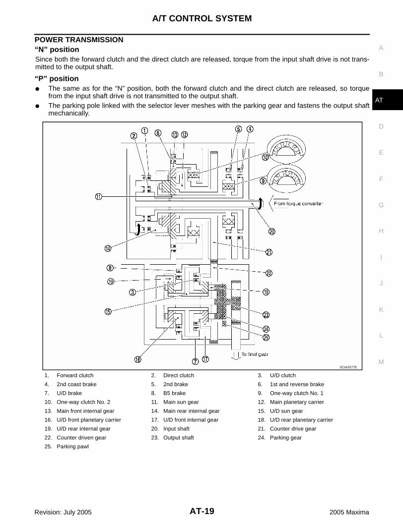
POWER TRANSMISSION “N” positionSince both the forward clutch and the direct clutch are released, torque from the input shaft drive is not trans-mitted to the output shaft.
“P” position The same as for the “N” position, both the forward clutch and the direct clutch are released, so torque
from the input shaft drive is not transmitted to the output shaft. The parking pole linked with the selector lever meshes with the parking gear and fastens the output shaft
mechanically.
1. Forward clutch 2. Direct clutch 3. U/D clutch
4. 2nd coast brake 5. 2nd brake 6. 1st and reverse brake
7. U/D brake 8. B5 brake 9. One-way clutch No. 1
10. One-way clutch No. 2 11. Main sun gear 12. Main planetary carrier
13. Main front internal gear 14. Main rear internal gear 15. U/D sun gear
16. U/D front planetary carrier 17. U/D front internal gear 18. U/D rear planetary carrier
19. U/D rear internal gear 20. Input shaft 21. Counter drive gear
22. Counter driven gear 23. Output shaft 24. Parking gear
25. Parking pawl
SCIA2577E

AT-20
A/T CONTROL SYSTEM
Revision: July 2005 2005 Maxima
“D” position 1st gear1. Input shaft rotates clockwise.2. Forward clutch operates. (Connect input shaft to main rear internal gear.)3. Main rear internal gear rotates clockwise.4. Main rear planetary pinion gear rotates itself clockwise.5. Main front large planetary pinion gear rotates itself clockwise for rear planetary pinion and one.6. Main front small planetary pinion gear rotates itself counterclockwise.7. Main front internal gear is going to rotates counterclockwise.8. One-way clutch No. 2 operates. (Lock counterclockwise rotation of main front internal gear.)9. Main planetary carrier revolves clockwise due to reaction force of front small planetary pinion gear.10. Counter drive gear rotates clockwise for main planetary carrier and one.11. Counter driven gear rotates counterclockwise.12. U/D front internal gear rotates counterclockwise for counter driven gear and one.13. U/D front planetary pinion gear rotates itself counterclockwise.14. U/D sun gear rotates clockwise.15. U/D rear planetary pinion gear rotates itself counterclockwise.16. B5 brake operate. (Lock rotation of U/D rear planetary carrier.)17. U/D rear internal gear rotates counterclockwise.18. U/D front planetary carrier and output shaft rotates counterclockwise for U/D rear internal gear and one.19. Final gear clockwise. During deceleration, main front internal gear clockwise due to rotation itself clockwise of main front small
planetary pinion gear, but driving force loses due to free of one-way clutch No. 2. Therefore, engine brakedoes not operate.

A/T CONTROL SYSTEM
AT-21
D
E
F
G
H
I
J
K
L
M
A
B
AT
Revision: July 2005 2005 Maxima
1. Forward clutch 2. Direct clutch 3. U/D clutch
4. 2nd coast brake 5. 2nd brake 6. 1st and reverse brake
7. U/D brake 8. B5 brake 9. One-way clutch No. 1
10. One-way clutch No. 2 11. Main sun gear 12. Main planetary carrier
13. Main front internal gear 14. Main rear internal gear 15. U/D sun gear
16. U/D front planetary carrier 17. U/D front internal gear 18. U/D rear planetary carrier
19. U/D rear internal gear 20. Input shaft 21. Counter drive gear
22. Counter driven gear 23. Output shaft 24. Parking gear
25. Parking pawl
SCIA2585E
AT-22
A/T CONTROL SYSTEM
Revision: July 2005 2005 Maxima
“M1” position 1st gear1. Input shaft rotates clockwise.2. Forward clutch operates. (Connect input shaft to main rear internal gear.)3. Main rear internal gear rotates clockwise.4. Main rear planetary pinion gear rotates itself clockwise.5. Main front large planetary pinion gear rotates itself clockwise for rear planetary pinion gear and one. 6. Main front small planetary pinion gear rotates itself counterclockwise.7. Main front internal gear is going to rotates counterclockwise.8. 1st and reverse brake operates. (Lock rotation of main front internal gear.)9. Main planetary carrier revolves clockwise due to reaction force of front small planetary pinion gear.10. Counter drive gear rotates clockwise for main planetary carrier and one.11. Counter driven gear rotates counterclockwise.12. U/D front internal gear rotates counterclockwise for counter driven gear and one.13. U/D front planetary pinion gear rotates itself counterclockwise.14. U/D sun gear rotates clockwise.15. U/D rear planetary pinion gear rotates itself counterclockwise.16. B5 brake operate. (Lock rotation of U/D rear planetary carrier.)17. U/D rear internal gear rotates counterclockwise.18. U/D front planetary carrier and output shaft rotates counterclockwise for U/D rear internal gear and one.19. Final gear clockwise. During deceleration, driving force is connected to input shaft directly without one-way clutch. Therefore,
engine brake operates.

A/T CONTROL SYSTEM
AT-23
D
E
F
G
H
I
J
K
L
M
A
B
AT
Revision: July 2005 2005 Maxima
1. Forward clutch 2. Direct clutch 3. U/D clutch
4. 2nd coast brake 5. 2nd brake 6. 1st and reverse brake
7. U/D brake 8. B5 brake 9. One-way clutch No. 1
10. One-way clutch No. 2 11. Main sun gear 12. Main planetary carrier
13. Main front internal gear 14. Main rear internal gear 15. U/D sun gear
16. U/D front planetary carrier 17. U/D front internal gear 18. U/D rear planetary carrier
19. U/D rear internal gear 20. Input shaft 21. Counter drive gear
22. Counter driven gear 23. Output shaft 24. Parking gear
25. Parking pawl
SCIA2586E

AT-24
A/T CONTROL SYSTEM
Revision: July 2005 2005 Maxima
“D”, “M2” positions 2nd gear1. Input shaft rotates clockwise.2. Forward clutch operates. (Connect input shaft to main rear internal gear.)3. Main rear internal gear rotates clockwise.4. Main rear planetary pinion gear rotates itself clockwise.5. Main front large planetary pinion gear rotates itself clockwise for rear planetary pinion and one.6. 2nd brake and 2nd coast brake operates.7. One-way clutch No. 1 operates. (Lock rotation of main sun gear.)8. Main planetary carrier revolves clockwise due to reaction force of front large planetary pinion gear.9. Counter drive gear rotates clockwise for main planetary carrier and one.10. Counter driven gear rotates counterclockwise.11. U/D front internal gear rotates counterclockwise for counter driven gear and one.12. U/D front planetary pinion gear rotates itself counterclockwise.13. U/D sun gear rotates clockwise.14. U/D rear planetary pinion gear rotates itself counterclockwise.15. B5 brake operate. (Lock rotation of U/D rear planetary carrier.)16. U/D rear internal gear rotates counterclockwise.17. U/D front planetary carrier and output shaft rotates counterclockwise for U/D rear internal gear and one.18. Final gear clockwise. During deceleration, driving force is connected to input shaft directly without one-way clutch. Therefore,
engine brake operates.

A/T CONTROL SYSTEM
AT-25
D
E
F
G
H
I
J
K
L
M
A
B
AT
Revision: July 2005 2005 Maxima
1. Forward clutch 2. Direct clutch 3. U/D clutch
4. 2nd coast brake 5. 2nd brake 6. 1st and reverse brake
7. U/D brake 8. B5 brake 9. One-way clutch No. 1
10. One-way clutch No. 2 11. Main sun gear 12. Main planetary carrier
13. Main front internal gear 14. Main rear internal gear 15. U/D sun gear
16. U/D front planetary carrier 17. U/D front internal gear 18. U/D rear planetary carrier
19. U/D rear internal gear 20. Input shaft 21. Counter drive gear
22. Counter driven gear 23. Output shaft 24. Parking gear
25. Parking pawl
SCIA2587E

AT-26
A/T CONTROL SYSTEM
Revision: July 2005 2005 Maxima
“D”, “M3” positions 3rd gear1. Input shaft rotates clockwise.2. Forward clutch operates. (Connect input shaft to main rear internal gear.)3. Main rear internal gear rotates clockwise.4. Main rear planetary pinion gear rotates itself clockwise.5. Main front large planetary pinion gear rotates itself clockwise for rear planetary pinion and one.6. 2nd brake and 2nd coast brake operates.7. One-way clutch No. 1 operates. (Lock rotation of main sun gear.)8. Main planetary carrier revolves clockwise due to reaction force of front large planetary pinion gear.9. Counter drive gear rotates clockwise for main planetary carrier and one.10. Counter driven gear rotates counterclockwise.11. U/D front internal gear rotates counterclockwise for counter driven gear and one.12. U/D front planetary pinion gear rotates itself counterclockwise.13. U/D brake operate. (Lock rotation of U/D sun gear.)14. U/D front planetary carrier revolves counterclockwise due to reaction force of U/D front planetary pinion
gear.15. U/D rear internal gear and output shaft rotates counterclockwise for U/D front planetary carrier and one.16. Final gear clockwise. During deceleration, driving force is connected to input shaft directly without one-way clutch. Therefore,
engine brake operates.

A/T CONTROL SYSTEM
AT-27
D
E
F
G
H
I
J
K
L
M
A
B
AT
Revision: July 2005 2005 Maxima
1. Forward clutch 2. Direct clutch 3. U/D clutch
4. 2nd coast brake 5. 2nd brake 6. 1st and reverse brake
7. U/D brake 8. B5 brake 9. One-way clutch No. 1
10. One-way clutch No. 2 11. Main sun gear 12. Main planetary carrier
13. Main front internal gear 14. Main rear internal gear 15. U/D sun gear
16. U/D front planetary carrier 17. U/D front internal gear 18. U/D rear planetary carrier
19. U/D rear internal gear 20. Input shaft 21. Counter drive gear
22. Counter driven gear 23. Output shaft 24. Parking gear
25. Parking pawl
SCIA2588E

AT-28
A/T CONTROL SYSTEM
Revision: July 2005 2005 Maxima
“D”, “M4” positions 4th gear1. Input shaft rotates clockwise.2. Forward clutch operates. (Connect input shaft to main rear internal gear.)3. Main rear internal gear rotates clockwise.4. Main rear planetary pinion gear rotates itself clockwise.5. Main front large planetary pinion gear rotates itself clockwise for rear planetary pinion and one.6. 2nd brake and 2nd coast brake operates.7. One-way clutch No. 1 operates. (Lock rotation of main sun gear.)8. Main planetary carrier revolves clockwise due to reaction force of front large planetary pinion gear.9. Counter drive gear rotates clockwise for main planetary carrier and one.10. Counter driven gear rotates counterclockwise.11. U/D front internal gear rotates counterclockwise for counter driven gear and one.12. U/D clutch operate. (Connect U/D sun gear to U/D front planetary carrier.)13. U/D front planetary pinion gear cannot rotate itself, and U/D unit rotates counterclockwise as one.14. Output shaft rotates counterclockwise for U/D unit and one.15. Final gear clockwise. During deceleration, driving force is connected to input shaft directly without one-way clutch. Therefore,
engine brake operates.

A/T CONTROL SYSTEM
AT-29
D
E
F
G
H
I
J
K
L
M
A
B
AT
Revision: July 2005 2005 Maxima
1. Forward clutch 2. Direct clutch 3. U/D clutch
4. 2nd coast brake 5. 2nd brake 6. 1st and reverse brake
7. U/D brake 8. B5 brake 9. One-way clutch No. 1
10. One-way clutch No. 2 11. Main sun gear 12. Main planetary carrier
13. Main front internal gear 14. Main rear internal gear 15. U/D sun gear
16. U/D front planetary carrier 17. U/D front internal gear 18. U/D rear planetary carrier
19. U/D rear internal gear 20. Input shaft 21. Counter drive gear
22. Counter driven gear 23. Output shaft 24. Parking gear
25. Parking pawl
SCIA2592E

AT-30
A/T CONTROL SYSTEM
Revision: July 2005 2005 Maxima
“D”, “M5” positions 5th gear1. Input shaft rotates clockwise.2. Forward clutch operates. (Connect input shaft to main rear internal gear.)3. Direct clutch operates. (Connect input shaft to main sun gear.)4. Main rear planetary pinion gear cannot rotate itself, and main rear planetary unit rotates clockwise as one.5. Main front large planetary pinion gear cannot rotate itself for main rear planetary pinion gear and one, and
main front planetary unit rotates clockwise as one.6. Counter drive gear rotates clockwise for main front planetary unit and one.7. Counter driven gear rotates counterclockwise.8. U/D front internal gear rotates counterclockwise for counter driven gear and one.9. U/D clutch operate. (Connect U/D sun gear to U/D front planetary carrier.)10. U/D front planetary pinion gear cannot rotate itself, and U/D unit rotates counterclockwise as one.11. Output shaft rotates counterclockwise for U/D unit and one.12. Final gear clockwise. During deceleration, driving force is connected to input shaft directly without one-way clutch. Therefore,
engine brake operates.

A/T CONTROL SYSTEM
AT-31
D
E
F
G
H
I
J
K
L
M
A
B
AT
Revision: July 2005 2005 Maxima
1. Forward clutch 2. Direct clutch 3. U/D clutch
4. 2nd coast brake 5. 2nd brake 6. 1st and reverse brake
7. U/D brake 8. B5 brake 9. One-way clutch No. 1
10. One-way clutch No. 2 11. Main sun gear 12. Main planetary carrier
13. Main front internal gear 14. Main rear internal gear 15. U/D sun gear
16. U/D front planetary carrier 17. U/D front internal gear 18. U/D rear planetary carrier
19. U/D rear internal gear 20. Input shaft 21. Counter drive gear
22. Counter driven gear 23. Output shaft 24. Parking gear
25. Parking pawl
SCIA2593E

AT-32
A/T CONTROL SYSTEM
Revision: July 2005 2005 Maxima
“R” position1. Input shaft rotates clockwise.2. Direct clutch operates. (Connect input shaft to main sun gear.)3. Main sun gear rotates clockwise.4. Main rear planetary pinion gear rotates itself clockwise.5. Main front large planetary pinion gear rotates itself counterclockwise for rear planetary pinion gear and
one.6. Main front small planetary pinion gear rotates itself clockwise.7. 1st and reverse brake operates. (Lock rotation of main front internal gear.)8. Main planetary carrier revolves counterclockwise due to reaction force of front small planetary pinion gear.9. Counter drive gear rotates counterclockwise for main planetary carrier and one.10. Counter driven gear rotates clockwise.11. U/D front internal gear rotates clockwise for counter driven gear and one.12. U/D front planetary pinion gear rotates itself clockwise.13. U/D sun gear rotates counterclockwise.14. U/D rear planetary pinion gear rotates itself clockwise.15. B5 brake operate. (Lock rotation of U/D rear planetary carrier.)16. U/D rear internal gear rotates clockwise.17. U/D front planetary carrier and output shaft rotates clockwise for U/D rear internal gear and one.18. Final gear counterclockwise. During deceleration, driving force is connected to input shaft directly without one-way clutch. Therefore,
engine brake operates.

A/T CONTROL SYSTEM
AT-33
D
E
F
G
H
I
J
K
L
M
A
B
AT
Revision: July 2005 2005 Maxima
1. Forward clutch 2. Direct clutch 3. U/D clutch
4. 2nd coast brake 5. 2nd brake 6. 1st and reverse brake
7. U/D brake 8. B5 brake 9. One-way clutch No. 1
10. One-way clutch No. 2 11. Main sun gear 12. Main planetary carrier
13. Main front internal gear 14. Main rear internal gear 15. U/D sun gear
16. U/D front planetary carrier 17. U/D front internal gear 18. U/D rear planetary carrier
19. U/D rear internal gear 20. Input shaft 21. Counter drive gear
22. Counter driven gear 23. Output shaft 24. Parking gear
25. Parking pawl
SCIA2594E

AT-34
A/T CONTROL SYSTEM
Revision: July 2005 2005 Maxima
TCM Function ECS00A0V
The function of the TCM is to: Receive input signals sent from various switches and sensors. Determine required line pressure, shifting point, lock-up operation, and engine brake operation. Send required output signals to the respective solenoids.
CONTROL SYSTEM OUTLINE The automatic transaxle senses vehicle operating conditions through various sensors or signals. It alwayscontrols the optimum shift position and reduces shifting and lock-up shocks.
CONTROL SYSTEM DIAGRAM
SENSORS (or SIGNAL)
TCM
ACTUATORS
PNP switchThrottle angle signalThrottle position signalEngine speed signalEngine torque signalA/T fluid temperature sensorRevolution sensorTurbine revolution sensorVehicle speed signalManual mode switch signalStop lamp switch signal
Shift controlLine pressure controlLock-up controlEngine brake controlTiming controlFail-safe controlSelf-diagnosisCONSULT-II communication lineCAN communication lineOn board diagnosis
Shift solenoid valve AShift solenoid valve BShift solenoid valve CShift solenoid valve DShift solenoid valve EPressure control solenoid valve APressure control solenoid valve BPressure control solenoid valve CA/T CHECK indicator lamp
WCIA0445E

A/T CONTROL SYSTEM
AT-35
D
E
F
G
H
I
J
K
L
M
A
B
AT
Revision: July 2005 2005 Maxima
Input/Output Signal of TCM ECS00A0W
*1: Spare for revolution sensor*2: Spare for throttle angle signal*3: If these input and output signals are different, the TCM triggers the fail-safe function.*4: Used as a condition for starting self-diagnostics; if self-diagnostics are not started, it is judged that there is some kind of error.*5: CAN communications.
CAN Communication ECS00A0X
SYSTEM DESCRIPTION CAN (Controller Area Network) is a serial communication line for real time application. It is an on-vehicle mul-tiplex communication line with high data communication speed and excellent error detection ability. Many elec-tronic control units are equipped onto a vehicle, and each control unit shares information and links with othercontrol units during operation (not independent). In CAN communication, control units are connected with 2communication lines (CAN H line, CAN L line) allowing a high rate of information transmission with less wiring.Each control unit transmits/receives data but selectively reads required data only.For details, refer to LAN-7, "CAN COMMUNICATION" .
Control itemLine
pressurecontrol
Vehicle speed control
Shift control
Lock-up control
Engine brake control
Fail-safe function
(*3)
Self-diag-nostics function
Input
Throttle angle signal(*5) X X X X X X X
Throttle position signal(*5) X(*2) X(*2) X X(*2) X(*4)
Revolution sensor X X X X X X X
Turbine revolution sensor X X X X X X
Vehicle speed signal MTR(*1) (*5) X X X X X X
Engine speed signals(*5) X X X X X
Engine torque signals(*5) X X X X X X
PNP switch X X X X X X X(*4)
Manual mode switch X X X X X
Stop lamp switch signal(*5) X X X X(*4)
A/T fluid temperature sensor X X X X X X
ASCDOperation signal(*5) X X X
Overdrive cancel signal(*5) X X X
TCM power supply voltage signal X X X X X X X
Out-put
Shift solenoid valve A/B/C/D/E X X X X
Pressure control solenoid valve A X X X X X X X
Pressure control solenoid valve B X X X X X
Pressure control solenoid valve C X X X X
Self-diagnostics table(*5) X

AT-36
A/T CONTROL SYSTEM
Revision: July 2005 2005 Maxima
Line Pressure Control ECS00A0Y
The pressure control solenoid valve A controls linear line pressure by control signal from TCM and linepressure for clutches and brakes to reduce shift shock.
This pressure control solenoid valve A controls the pressure regulator valve as the signal pressure andadjusts the pressure of the operating oil discharged from the oil pump to the line pressure most appropri-ate to the driving state.
LINE PRESSURE CONTROL IS BASED ON THE TCM LINE PRESSURE CHARACTERISTIC PATTERN In order to obtain the most appropriate line pressure characteristic to meet the current driving state, the TCMcontrols the pressure control solenoid valve A current and thus controls the line pressure.
Shift Control ECS00A0Z
The clutch pressure control solenoid is controlled by the signals from the switches and sensors. Thus, theclutch pressure is adjusted to be appropriate to the engine load state and vehicle driving state. It becomespossible to finely control the clutch hydraulic pressure with high precision and a smoother shift change charac-teristic is attained.
Basically TCM programmed for economy mode, but TCM changes to several shift schedule automaticallyaccording to specified condition.
SCIA2605E
SCIA2610E

A/T CONTROL SYSTEM
AT-37
D
E
F
G
H
I
J
K
L
M
A
B
AT
Revision: July 2005 2005 Maxima
SPECIAL SHIFT MODEUpslope ModeWhen TCM detects upslope from load of engine torque and decrease of acceleration, this mode changes shiftpoints in high-speed side according to the upslope degree and avoids busy shift of A/T.
Downslope ModeWhen TCM detects downslope from increase of acceleration with accelerator full close, this mode operatesmoderate engine brake by changing shift points in high-speed side.
Hot Mode Control This control lowers ATF temperature by changing shift points when the temperature is extremely high.
MANUAL MODEDriver oneself can select favorite gear and enjoy sports driving of manual transmission sense by shifting leverfrom D position to manual mode position and + (up shift) / - (down shift). But lock-up control is operated auto-matically. Shift control is operated again by shifting from manual gear position to D position. Following controlis operated when manual mode.
Automated Up Shift ControlIn order to avoid the over speed of the engine, up shift operate automatically, if it becomes over a constantvehicle speed.
Automated Down Shift ControlIn order to avoid the stall of the engine, down shift operate automatically, if it becomes under a constant vehi-cle speed.
Up Shift Permission ControlIn order to avoid the stall of the engine, up shift is done only at over a constant vehicle speed.
Down Shift Permission ControlIn order to avoid the over speed of the engine, down shift is done only at under a constant vehicle speed.
UP/DOWN SHIFT LEARNING CONTROLThis control learns the pressure to each clutch or brake in order to reduce shifting shock at each shifting (Up,Down, Manual down, Coast down).
N-D SHIFT CONTROLThis control improves the N-D shift quality due to controlling line pressure solenoid valve according to forwardclutch piston stroke learned in N-D shift learning control and applying best hydraulic pressure to forward clutchat N-D shift.
N-D SHIFT LEARNING CONTROLThis control learns the forward clutch hydraulic pressure due to monitoring a forward clutch engaging time anda rotation change rate.
N-R SHIFT CONTROLThis control improves the N-R shift quality due to controlling shift pressure solenoid valve according to directclutch piston stroke learned in N-R shift learning control and applying best hydraulic pressure to direct clutchat N-R shift.
N-R SHIFT LEARNING CONTROLThis control learns the direct clutch hydraulic pressure due to monitoring a direct clutch engaging time and arotation change rate.
TORQUE REDUCTION CONTROLThis control improves the shift quality due to sending torque reduction request signal from TCM to ECM andcutting engine torque increase of shift at N-D shift, N-R shift and 1 ⇔ 2 ⇔ 3 ⇔ 4 ⇔ 5.If accelerator pedal is depressed rapidly, this control establishes the upper limit value of engine torque andavoids engine flare at 2 ⇔ 3, 3 ⇔ 4 and 4 2 of clutch to clutch shift.

AT-38
A/T CONTROL SYSTEM
Revision: July 2005 2005 Maxima
Lock-Up Control ECS00A10
The torque converter clutch piston in the torque converter is engaged to eliminate torque converter slip toincrease power transmission efficiency.The torque converter clutch control valve operation is controlled by the pressure control solenoid valve C,which is controlled by a signal from TCM, and the torque converter clutch control valve engages or releasesthe torque converter clutch piston.
Lock-up Operation Condition Table
TORQUE CONVERTER CLUTCH CONTROL VALVE CONTROL Lock-up Control System Diagram
Lock-up Released In the lock-up released state, the torque converter clutch control valve is set into the unlocked state by the
pressure control solenoid valve C and the lock-up apply pressure is drained.In this way, the torque converter clutch piston is not coupled.
Lock-up Applied In the lock-up applied state, the torque converter clutch control valve is set into the locked state by the
pressure control solenoid valve C and lock-up apply pressure is generated.In this way, the torque converter clutch piston is pressed and coupled.
Selector lever D position M5 position M4 position M3 position
Gear position 5 4 5 4 3
Lock-up × – × × ×
Slip lock-up × × – – –
SCIA2612E

A/T CONTROL SYSTEM
AT-39
D
E
F
G
H
I
J
K
L
M
A
B
AT
Revision: July 2005 2005 Maxima
SMOOTH LOCK-UP CONTROL When shifting from the lock-up released state to the lock-up applied state, the current output to the pressurecontrol solenoid valve C is controlled with the TCM. In this way, when shifting to the lock-up applied state, thetorque converter clutch is temporarily set to the half-clutched state to reduce the shock.
Half-Clutched State The current output from the TCM to the pressure control solenoid valve C is varied to steadily increase the
pressure control solenoid valve C pressure.In this way, the lock-up apply pressure gradually rises and while the torque converter clutch piston is putinto half-clutched status, the torque converter clutch piston operating pressure is increased and the cou-pling is completed smoothly.
Slip Lock-up Control In the slip region, the pressure control solenoid valve C current is controlled with the TCM to put it into the
half-clutched state. This absorbs the engine torque fluctuation and lock-up operates from low speed.This raises the fuel efficiency for 4th and 5th gears at both low speed and when the accelerator has a lowdegree of opening.

AT-40
ON BOARD DIAGNOSTIC (OBD) SYSTEM
Revision: July 2005 2005 Maxima
ON BOARD DIAGNOSTIC (OBD) SYSTEM PFP:00028
Introduction ECS00A11
The A/T system has two self-diagnostic systems.The first is the emission-related on board diagnostic system (OBD-II) performed by the TCM in combinationwith the ECM. The malfunction is indicated by the MIL (malfunction indicator lamp) and is stored as a DTC inthe ECM memory but not the TCM memory.The second is the TCM original self-diagnosis indicated by the A/T CHECK indicator lamp. The malfunction isstored in the TCM memory. The detected items are overlapped with OBD-II self-diagnostic items. For detail,refer to AT-75, "SELF-DIAG RESULT MODE" .
OBD-II Function for A/T System ECS00A12
The ECM provides emission-related on board diagnostic (OBD-II) functions for the A/T system. One functionis to receive a signal from the TCM used with OBD-related parts of the A/T system. The signal is sent to theECM when a malfunction occurs in the corresponding OBD-related part. The other function is to indicate adiagnostic result by means of the MIL (malfunction indicator lamp) on the instrument panel. Sensors, switchesand solenoid valves are used as sensing elements.The MIL automatically illuminates in One or Two Trip Detection Logic when a malfunction is sensed in relationto A/T system parts.
One or Two Trip Detection Logic of OBD-II ECS00A13
ONE TRIP DETECTION LOGICIf a malfunction is sensed during the first test drive, the MIL will illuminate and the malfunction will be stored inthe ECM memory as a DTC. The TCM is not provided with such a memory function.
TWO TRIP DETECTION LOGICWhen a malfunction is sensed during the first test drive, it is stored in the ECM memory as a 1st trip DTC(diagnostic trouble code) or 1st trip freeze frame data. At this point, the MIL will not illuminate. — 1st TripIf the same malfunction as that experienced during the first test drive is sensed during the second test drive,the MIL will illuminate. — 2nd TripThe “trip” in the “One or Two Trip Detection Logic” means a driving mode in which self-diagnosis is performedduring vehicle operation.
OBD-II Diagnostic Trouble Code (DTC) ECS00A14
HOW TO READ DTC AND 1ST TRIP DTCDTC and 1st trip DTC can be read by the following methods.( with CONSULT-II or GST) CONSULT-II or GST (Generic Scan Tool) Examples: P0705, P0710 etc.These DTC are prescribed by SAE J2012.(CONSULT-II also displays the malfunctioning component or system.) 1st trip DTC No. is the same as DTC No. Output of the diagnostic trouble code indicates that the indicated circuit has a malfunction. How-
ever, in case of the Mode II and GST, they do not indicate whether the malfunction is still occurringor occurred in the past and returned to normal.CONSULT-II can identify them as shown below, therefore, CONSULT-II (if available) is recom-mended.
A sample of CONSULT-II display for DTC and 1st trip DTC is shownon the next page. DTC or 1st trip DTC of a malfunction is displayedin SELF-DIAGNOSTIC RESULTS mode for “ENGINE” with CON-SULT-II. Time data indicates how many times the vehicle was drivenafter the last detection of a DTC.
BCIA0030E

ON BOARD DIAGNOSTIC (OBD) SYSTEM
AT-41
D
E
F
G
H
I
J
K
L
M
A
B
AT
Revision: July 2005 2005 Maxima
If the DTC is being detected currently, the time data will be “0”.
If a 1st trip DTC is stored in the ECM, the time data will be “1t”.
Freeze Frame Data and 1st Trip Freeze Frame DataThe ECM has a memory function, which stores the driving condition such as fuel system status, calculatedload value, engine coolant temperature, short term fuel trim, long term fuel trim, engine speed and vehiclespeed at the moment the ECM detects a malfunction.Data which are stored in the ECM memory, along with the 1st trip DTC, are called 1st trip freeze frame data,and the data, stored together with the DTC data, are called freeze frame data and displayed on CONSULT-IIor GST. The 1st trip freeze frame data can only be displayed on the CONSULT-II screen, not on the GST. Fordetail, refer to EC-54, "FREEZE FRAME DATA AND 1ST TRIP FREEZE FRAME DATA" .Only one set of freeze frame data (either 1st trip freeze frame data or freeze frame data) can be stored in theECM. 1st trip freeze frame data is stored in the ECM memory along with the 1st trip DTC. There is no priorityfor 1st trip freeze frame data and it is updated each time a different 1st trip DTC is detected. However, oncefreeze frame data (2nd trip detection/MIL on) is stored in the ECM memory, 1st trip freeze frame data is nolonger stored. Remember, only one set of freeze frame data can be stored in the ECM. The ECM has the fol-lowing priorities to update the data.
Both 1st trip freeze frame data and freeze frame data (along with the DTC) are cleared when the ECM mem-ory is erased.
HOW TO ERASE DTCThe diagnostic trouble code can be erased by CONSULT-II, GST or ECM DIAGNOSTIC TEST MODE asdescribed following. If the battery cable is disconnected, the diagnostic trouble code will be lost within 24 hours. When you erase the DTC, using CONSULT-II or GST is easier and quicker than switching the mode
selector on the ECM.The following emission-related diagnostic information is cleared from the ECM memory when erasing DTCrelated to OBD-II. For details, refer to EC-50, "EMISSION-RELATED DIAGNOSTIC INFORMATION ITEMS" . Diagnostic trouble codes (DTC) 1st trip diagnostic trouble codes (1st trip DTC) Freeze frame data
SAT015K
SAT016K
Priority Items
1Freeze frame data
Misfire — DTC: P0300 - P0306Fuel Injection System Function — DTC: P0171, P0172, P0174, P0175
2 Except the above items (Includes A/T related items)
3 1st trip freeze frame data

AT-42
ON BOARD DIAGNOSTIC (OBD) SYSTEM
Revision: July 2005 2005 Maxima
1st trip freeze frame data System readiness test (SRT) codes Test values
HOW TO ERASE DTC (WITH CONSULT-II)
If a DTC is displayed for both ECM and TCM, it is necessary to be erased for both ECM and TCM.1. If the ignition switch stays “ON” after repair work, be sure to turn ignition switch “OFF” once. Wait at least
10 seconds and then turn it “ON” (engine stopped) again.2. Turn CONSULT-II “ON” and touch “A/T”.3. Touch “SELF-DIAG RESULTS”.4. Touch “ERASE”. (The DTC in the TCM will be erased.) Then touch “BACK” twice.5. Touch “ENGINE”.6. Touch “SELF-DIAG RESULTS”.7. Touch “ERASE”. (The DTC in the ECM will be erased.)
HOW TO ERASE DTC (WITH GST)1. If the ignition switch stays “ON” after repair work, be sure to turn ignition switch “OFF” once. Wait at least
10 seconds and then turn it “ON” (engine stopped) again.2. Erase DTC with TCM. Refer to AT-82, "Erase self-diagnosis" . (The engine warm-up step can be skipped
when performing the diagnosis only to erase the DTC.)3. Select Mode 4 with Generic Scan Tool (GST). For details, refer to EC-143, "Generic Scan Tool (GST)
Function" .
HOW TO ERASE DTC (NO TOOLS)
The A/T CHECK indicator lamp is located on the instrument panel.
WCIA0405E

ON BOARD DIAGNOSTIC (OBD) SYSTEM
AT-43
D
E
F
G
H
I
J
K
L
M
A
B
AT
Revision: July 2005 2005 Maxima
1. If the ignition switch stays “ON” after repair work, be sure to turn ignition switch “OFF” once. Wait at least10 seconds and then turn it “ON” (engine stopped) again.
2. Erase DTC with TCM. Refer to AT-82, "Erase self-diagnosis" . (The engine warm-up step can be skippedwhen performing the diagnosis only to erase the DTC.)
3. Erase DTC with ECM. Refer to EC-62, "How to Erase DTC" .
Malfunction Indicator Lamp (MIL) ECS00A15
DESCRIPTION The MIL is located on the instrument panel.1. The MIL will light up when the ignition switch is turned “ON” with-
out the engine running. This is a bulb check. If the MIL does not light up, refer to DI-41, "WARNING LAMPS" ,
or see EC-64, "Malfunction Indicator Lamp (MIL)" .2. When the engine is started, the MIL should go off.
If the MIL remains on, the on board diagnostic system hasdetected an engine system malfunction.
SEF217U

AT-44
TROUBLE DIAGNOSIS
Revision: July 2005 2005 Maxima
TROUBLE DIAGNOSIS PFP:00004
DTC Inspection Priority Chart ECS00A16
If some DTCs are displayed at the same time, perform inspections one by one based on the following prioritychart.NOTE:If DTC U1000 is displayed with other DTCs, first perform the trouble diagnosis for DTC U1000. Refer toAT-83 .
Fail-Safe ECS00A17
The TCM has an electrical fail-safe mode. This mode makes it possible to operate even if there is a malfunc-tion in a main electronic control input/output signal circuit. In fail-safe mode, a driving condition is selected according to the malfunctioning location, and line pressure isset at the maximum. For this reason, the customer will be subjected to uncomfortable “slipping” or “poor accel-eration” of the vehicle.In that case, handle according to the “diagnostics flow” (Refer to AT-48 ).
FAIL-SAFE FUNCTIONIf any malfunction occurs in a sensor or solenoid, this function controls the A/T to make driving possible.NOTE:Line pressure is set at the maximum in fail-safe mode. Although gear position differs depending onthe type of fail-safe modes, CONSULT-II indicates “5th”.
Priority Detected items (DTC)
1 U1000 CAN communication line
2 Except above
DTC Malfunction items Fail-safe*
P0500 Vehicle speed signal No learning control.
P0613 TCM processor Fail-safe mode 4
P0705 PNP switch Fail-safe mode 4
P0710 ATF temperature sensor circuitSets ATF temperature data at 111°C (232°F) after 15 minutes. Inhibits lock-up control.
P0711 ATF temperature sensor functionSets ATF temperature data at 111°C (232°F) after 15 minutes. Inhibits lock-up control.
P0717 Turbine revolution sensor Fail-safe mode 1
P0722 Revolution sensorUses vehicle speed signal from combination meter as a substitute. Inhib-its learning control.
P0726Engine speed signal input circuit perfor-mance
Fail-safe mode 1
P0731 1st gear function No 1st gear, no control for N-D shift.
P0732 2nd gear functionFail-safe mode 1. Also, ECM restricts engine torque to prevent clutch slipping.
P0733 3rd gear functionFail-safe mode 1. Also, ECM restricts engine torque to prevent clutch slipping.
P0734 4th gear functionFail-safe mode 1. Also, ECM restricts engine torque to prevent clutch slipping.
P0735 5th gear functionFail-safe mode 1. Also, ECM restricts engine torque to prevent clutch slipping.
P0744 Lock-up function Fail-safe mode 1
P0745 Pressure control solenoid valve AFail-safe mode 1. Also, ECM restricts engine torque to prevent clutch slipping.

TROUBLE DIAGNOSIS
AT-45
D
E
F
G
H
I
J
K
L
M
A
B
AT
Revision: July 2005 2005 Maxima
*: For fail-safe modes 1 to 10, refer to AT-45, "Fail-safe mode list" .
Fail-safe mode list
P0750 Shift solenoid valve A
Any one of fail-safe modes
Fail-safe mode 1
Fail-safe mode 7. Also, ECM restricts input torque to prevent clutch slipping.
P0755 Shift solenoid valve B
Any one of fail-safe modes
Fail-safe mode 1
Fail-safe mode 8
P0760 Shift solenoid valve C
Any one of fail-safe modes
Fail-safe mode 2
Fail-safe mode 5
Fail-safe mode 9
P0762 Shift solenoid valve C stuck ONFail-safe mode 2. Also, ECM restricts engine torque to prevent clutch slipping.
P0765 Shift solenoid valve D
Any one of fail-safe modes
Fail-safe mode 1
Fail-safe mode 10. Also, ECM restricts input torque to prevent clutch slipping.
P0770 Shift solenoid valve E
Any one of fail-safe modes
Fail-safe mode 1. Also, ECM restricts engine torque to prevent clutch slipping.
Fail-safe mode 6. Also, ECM restricts engine torque to prevent clutch slipping.
P0775 Pressure control solenoid valve B Fail-safe mode 3
P0780 Shift functionFail-safe mode 1. Also, ECM restricts input torque to prevent clutch slip-ping.
P0795 Pressure control solenoid valve C Fail-safe mode 1
P0797 Pressure control solenoid valve C stuck ON Fail-safe mode 1
P0826 Manual mode switch No manual mode control.
P0882 TCM power input signal Fail-safe mode 1
P1726 Electric throttle control The accelerator opening angle is controlled by ECM according to a
pre-determined accelerator angle to make driving possible.
No lock-up, no learning control.
U1000 CAN communication circuit
Any one of fail-safe modes
Fail-safe mode 1
Fail-safe mode 1. Also, ECM restricts engine torque to prevent clutch slipping.
No learning control.
No lock-up, no learning control, no special shift mode control.
DTC Malfunction items Fail-safe*
Fail-safe mode Selector leverGear
position*1
Shift solenoid valvePressure control sole-
noid valve
A B C D E A B C
Fail-safe mode 1
D position4th OFF OFF OFF OFF OFF OFF OFF OFF
Manual mode: + (up shift)
Manual mode: - (down shift) 2nd OFF OFF ON OFF OFF OFF OFF OFF
R position Reverse OFF OFF OFF OFF ON OFF OFF OFF

AT-46
TROUBLE DIAGNOSIS
Revision: July 2005 2005 Maxima
*1: CONSULT-II indicates “5th”.*2: Reverse gear ratio difference (Gear ratio: 3.342)*3: 3rd gear ratio difference (Gear ratio: 2.301)
Fail-safe mode 2(CONSULT-II dis-plays “8”)
D position3rd OFF OFF ON ON OFF OFF OFF OFF
Manual mode: + (up shift)
Manual mode: - (down shift) 2nd OFF OFF ON OFF OFF OFF OFF OFF
R position Reverse OFF OFF ON OFF ON OFF OFF OFF
Fail-safe mode 3
D position4th OFF OFF OFF OFF OFF OFF OFF OFF
Manual mode: + (up shift)
Manual mode: - (down shift) 2nd OFF OFF ON OFF ON OFF OFF OFF
R position Reverse OFF OFF OFF OFF ON OFF OFF OFF
Fail-safe mode 4
D position4th OFF OFF OFF OFF OFF OFF OFF OFF
Manual mode: + (up shift)
Manual mode: - (down shift) 4th OFF OFF OFF OFF OFF OFF OFF OFF
R position Reverse OFF OFF OFF OFF OFF OFF OFF OFF
Fail-safe mode 5
D position4th OFF OFF OFF OFF OFF OFF OFF OFF
Manual mode: + (up shift)
Manual mode: - (down shift) 4th OFF OFF OFF OFF OFF OFF OFF OFF
R position Reverse OFF OFF OFF OFF ON OFF OFF OFF
Fail-safe mode 6
D position4th OFF OFF OFF OFF OFF OFF OFF OFF
Manual mode: + (up shift)
Manual mode: - (down shift) 2nd OFF OFF ON OFF OFF OFF OFF OFF
R position Reverse OFF OFF ON OFF OFF OFF OFF OFF
Fail-safe mode 7
D position4th ON OFF OFF OFF OFF OFF OFF OFF
Manual mode: + (up shift)
Manual mode: - (down shift) 2nd ON OFF ON OFF OFF OFF OFF OFF
R position Reverse*2 ON OFF ON ON OFF OFF OFF OFF
Fail-safe mode 8(CONSULT-II dis-plays “1”)
D position5th OFF ON OFF OFF OFF OFF OFF OFF
Manual mode: + (up shift)
Manual mode: - (down shift) (2nd)*3 OFF ON ON OFF OFF OFF OFF OFF
R position Reverse OFF ON OFF OFF ON OFF OFF OFF
Fail-safe mode 9(CONSULT-II dis-plays “8”)
D position4th OFF OFF OFF ON OFF OFF OFF OFF
Manual mode: + (up shift)
Manual mode: - (down shift) 4th OFF OFF OFF OFF OFF OFF OFF OFF
R position Reverse OFF OFF OFF OFF ON OFF OFF OFF
Fail-safe mode 10(CONSULT-II dis-plays “6”)
D position4th OFF OFF OFF ON OFF OFF OFF OFF
Manual mode: + (up shift)
Manual mode: - (down shift) 3rd OFF OFF ON ON OFF OFF OFF OFF
R position Reverse*2 OFF OFF ON ON OFF OFF OFF OFF
Fail-safe mode Selector leverGear
position*1
Shift solenoid valvePressure control sole-
noid valve
A B C D E A B C

TROUBLE DIAGNOSIS
AT-47
D
E
F
G
H
I
J
K
L
M
A
B
AT
Revision: July 2005 2005 Maxima
How To Perform Trouble Diagnosis For Quick and Accurate Repair ECS00A18
INTRODUCTIONThe TCM receives a signal from the vehicle speed signal, throttle position sensor (accelerator pedal positionsensor) or PNP switch and provides shift control or lock-up control via A/T solenoid valves.The TCM also communicates with the ECM by means of a signalsent from sensing elements used with the OBD-related parts of theA/T system for malfunction-diagnostic purposes. The TCM is capa-ble of diagnosing malfunctioning parts while the ECM can store mal-functions in its memory.Input and output signals must always be correct and stable in theoperation of the A/T system. The A/T system must be in good oper-ating condition and be free of valve seizure, solenoid valve malfunc-tion, etc.
It is much more difficult to diagnose an error that occurs intermit-tently rather than continuously. Most intermittent errors are causedby poor electric connections or improper wiring. In this case, carefulchecking of suspected circuits may help prevent the replacement ofgood parts.A visual check only may not find the cause of the errors. A road testwith CONSULT-II (or GST) or a circuit tester connected should beperformed. Follow the AT-48, "WORK FLOW" .
Before undertaking actual checks, take a few minutes to talk with acustomer who approaches with a driveability complaint. The cus-tomer can supply good information about such errors, especiallyintermittent ones. Find out what symptoms are present and underwhat conditions they occur. A “Diagnostic Worksheet” as shown onthe example (Refer to AT-49 ) should be used.Start your diagnosis by looking for “conventional” errors first. This willhelp troubleshoot driveability errors on an electronically controlledengine vehicle.Also check related Service bulletins.
SAT631IB
SAT632I
SEF234G

AT-48
TROUBLE DIAGNOSIS
Revision: July 2005 2005 Maxima
WORK FLOWA good understanding of the malfunction conditions can make troubleshooting faster and more accurate.In general, each customer feels differently about a malfunction. It is important to fully understand the symp-toms or conditions for a customer complaint.Make good use of the two sheets provided, “Information From Customer” (Refer to AT-49 ) and “DiagnosticWorksheet” (Refer to AT-49 ), to perform the best troubleshooting possible.
Work Flow Chart
*1. AT-49 *2. AT-49 *3. AT-44
*4. AT-54 *5. AT-54, AT-56 *6. AT-57
*7. AT-74 *8. AT-40 *9. AT-43
*10. AT-83 *11. AT-209 *12. AT-210
*13. AT-229 *14. AT-64 *15. AT-41
*16. AT-83 *17. AT-209 *18. EC-50
SCIA0501E

TROUBLE DIAGNOSIS
AT-49
D
E
F
G
H
I
J
K
L
M
A
B
AT
Revision: July 2005 2005 Maxima
DIAGNOSTIC WORKSHEETInformation From CustomerKEY POINTS WHAT..... Vehicle & A/T model WHEN..... Date, Frequencies WHERE..... Road conditions HOW..... Operating conditions, Symptoms
Diagnostic Worksheet Chart
Customer name MR/MS Model & Year VIN
Trans. Model Engine Mileage
Incident Date Manuf. Date In Service Date
Frequency Continuous Intermittent (times a day)
Symptoms Vehicle does not move. ( Any position Particular position)
No up-shift ( 1st → 2nd 2nd → 3rd 3rd → 4th 4th → 5th)
No down-shift ( 5th → 4th 4th → 3rd 3rd → 2nd 2nd → 1st)
Lock-up malfunction
Shift point too high or too low.
Shift shock or slip ( N → D Lock-up Any drive position)
Noise or vibration
No kick down
No pattern select
Others( )
Malfunction indicator lamp (MIL) Continuously lit Not lit
A/T Check indicator lamp Continuously lit Not lit
1 Read the item on cautions concerning fail-safe and understand the customer's complaint. AT-44
2
A/T fluid inspection
AT-54 Leak (Repair leak location.) State Amount
3
Stall test, time lag test and line pressure test
AT-54, AT-56
Stall test
Engine Torque converter one-way clutch Line pressure is low Forward clutch Direct clutch 1st and reverse brake
B5 brake One-way clutch No. 2 Oil pump Oil strainer Oil leak for each range circuit
Time lag test
Line pressure is low Forward clutch Direct clutch 1st and reverse brake One-way clutch No. 2
Oil pump Oil strainer Oil leak for “D” position circuit Oil leak for “R” position circuit
Line pressure inspection - Suspected part:

AT-50
TROUBLE DIAGNOSIS
Revision: July 2005 2005 Maxima
4
Perform all road tests and enter checks in required inspection items. AT-57
4-1.
Check before engine is started
AT-58 The A/T CHECK Indicator Lamp does come on. AT-210 . Perform self-diagnostics. Enter checks for detected items.
Vehicle speed sensor·MTR. AT-86 . TCM processor. AT-88 . PNP switch. AT-90 . A/T fluid temperature sensor circuit. AT-95 . A/T fluid temperature sensor performance. AT-100 . Turbine revolution sensor circuit. AT-105 . Vehicle speed sensor·A/T (revolution sensor) circuit. AT-109 . Engine speed input circuit performance. AT-113 . 1st gear function. AT-115 . 2nd gear function. AT-118 . 3rd gear function. AT-124 . 4th gear function. AT-130 . 5th gear function. AT-135 . Lock-up function. AT-141 . Shift function. AT-184 . Pressure control solenoid valve A. AT-144 . Pressure control solenoid valve B. AT-179 . Pressure control solenoid valve C. AT-188 . Shift solenoid valve A. AT-149 . Shift solenoid valve B. AT-154 . Shift solenoid valve C. AT-159 . Shift solenoid valve D. AT-169 . Shift solenoid valve E. AT-174 . Pressure control solenoid valve C stuck ON. AT-193 . Shift solenoid valve C stuck ON. AT-164 . Manual mode switch circuit. AT-198 . TCM power input signal. AT-204 . Electric throttle control system. AT-209 . CAN communication. AT-83 . Battery Other
4-2.
Idle inspection
AT-58
Engine Cannot Be Started in “P” and “N” Position. AT-212 . In “ P” Position, Vehicle Moves When Pushed. AT-212 . In “N” Position Vehicle Moves. AT-213 . Large Shock “N” to “D” Position. AT-214 . Vehicle Does Not Creep Backward In “R” Position. AT-215 . Vehicle does Not Creep Forward In “D” Position. AT-216 .
4-3.
Driving tests
AT-60
Part 1
Vehicle Cannot Be Started From D1. AT-217 . A/T Does Not Shift: D1 → D2. AT-217 . A/T Does Not Shift: D2 → D3. AT-218 . A/T Does Not Shift: D3 → D4. AT-219 . A/T Does Not Shift: D4 → D5. AT-220 . A/T Does Not Perform Lock-up. AT-221 A/T Does Not Hold Lock-up Condition. AT-222 . Lock-up Is Not Released. AT-223 .

TROUBLE DIAGNOSIS
AT-51
D
E
F
G
H
I
J
K
L
M
A
B
AT
Revision: July 2005 2005 Maxima
4 4-3
Part 2
AT-61 Vehicle Cannot Be Started From D1. AT-217 . A/T Does Not Shift: D1 → D2. AT-217 . A/T Does Not Shift: D2 → D3. AT-218 . A/T Does Not Shift: D3 → D4. AT-219 .
Part 3
AT-62
Cannot Be Changed To Manual Mode. AT-224 . A/T Does Not Shift: 5th gear → 4th gear. AT-225 . A/T Does Not Shift: 4th gear → 3rd gear. AT-226 . A/T Does Not Shift: 3rd gear → 2nd gear. AT-226 . A/T Does Not Shift: 2nd gear → 1st gear. AT-227 . Vehicle Does Not Decelerate By Engine Brake. AT-228 . Perform self-diagnostics Enter checks for detected items.
Vehicle speed sensor·MTR. AT-86 . TCM processor. AT-88 . PNP switch. AT-90 . A/T fluid temperature sensor circuit. AT-95 . A/T fluid temperature sensor performance. AT-100 . Turbine revolution sensor circuit. AT-105 . Vehicle speed sensor·A/T (revolution sensor) circuit. AT-109 . Engine speed input circuit performance. AT-113 . 1st gear function. AT-115 . 2nd gear function. AT-118 . 3rd gear function. AT-124 . 4th gear function. AT-130 . 5th gear function. AT-135 . Lock-up function. AT-141 . Shift function. AT-184 . Pressure control solenoid valve A. AT-144 . Pressure control solenoid valve B. AT-179 . Pressure control solenoid valve C. AT-188 . Shift solenoid valve A. AT-149 . Shift solenoid valve B. AT-154 . Shift solenoid valve C. AT-159 . Shift solenoid valve D. AT-169 . Shift solenoid valve E. AT-174 . Pressure control solenoid valve C stuck ON. AT-193 . Shift solenoid valve C stuck ON. AT-164 . Manual mode switch circuit. AT-198 . TCM power input signal. AT-204 . Electric throttle control system. AT-209 . CAN communication. AT-83 . Battery Other
5 Inspect each system for items found to be NG in the self-diagnostics and repair or replace the malfunction parts.
6 Perform all road tests and enter the checks again for the required items. AT-57
7 For any remaining NG items, perform the “diagnostics procedure” and repair or replace the malfunction parts. See the chart for diagnostics by symptoms. (This chart also contains other symptoms and inspection proce-dures.)
AT-64
8 Erase the results of the self-diagnostics from the TCM. AT-82

AT-52
TROUBLE DIAGNOSIS
Revision: July 2005 2005 Maxima
A/T Electrical Parts Location ECS00A19
WCIA0446E

TROUBLE DIAGNOSIS
AT-53
D
E
F
G
H
I
J
K
L
M
A
B
AT
Revision: July 2005 2005 Maxima
Circuit Diagram ECS00A1A
BCWA0296E
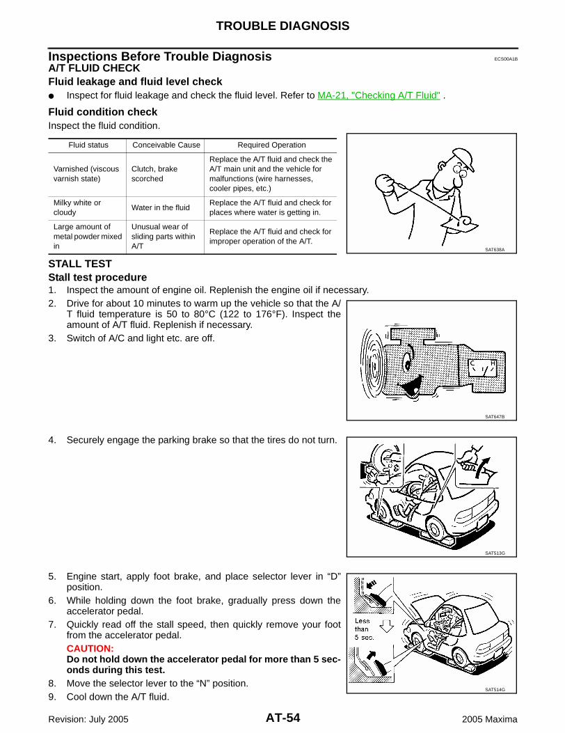
AT-54
TROUBLE DIAGNOSIS
Revision: July 2005 2005 Maxima
Inspections Before Trouble Diagnosis ECS00A1B
A/T FLUID CHECKFluid leakage and fluid level check Inspect for fluid leakage and check the fluid level. Refer to MA-21, "Checking A/T Fluid" .
Fluid condition checkInspect the fluid condition.
STALL TESTStall test procedure1. Inspect the amount of engine oil. Replenish the engine oil if necessary.2. Drive for about 10 minutes to warm up the vehicle so that the A/
T fluid temperature is 50 to 80°C (122 to 176°F). Inspect theamount of A/T fluid. Replenish if necessary.
3. Switch of A/C and light etc. are off.
4. Securely engage the parking brake so that the tires do not turn.
5. Engine start, apply foot brake, and place selector lever in “D”position.
6. While holding down the foot brake, gradually press down theaccelerator pedal.
7. Quickly read off the stall speed, then quickly remove your footfrom the accelerator pedal.CAUTION:Do not hold down the accelerator pedal for more than 5 sec-onds during this test.
8. Move the selector lever to the “N” position.9. Cool down the A/T fluid.
Fluid status Conceivable Cause Required Operation
Varnished (viscous varnish state)
Clutch, brake scorched
Replace the A/T fluid and check the A/T main unit and the vehicle for malfunctions (wire harnesses, cooler pipes, etc.)
Milky white or cloudy
Water in the fluidReplace the A/T fluid and check for places where water is getting in.
Large amount of metal powder mixed in
Unusual wear of sliding parts within A/T
Replace the A/T fluid and check for improper operation of the A/T.
SAT638A
SAT647B
SAT513G
SAT514G

TROUBLE DIAGNOSIS
AT-55
D
E
F
G
H
I
J
K
L
M
A
B
AT
Revision: July 2005 2005 Maxima
CAUTION:Run the engine at idle for at least one minute.
10. Repeat step 5 through 9 with selector lever in “manual mode” and “R” positions.
Judgement stall test
O: Stall speed within standard value positionH: Stall speed higher than standard valueL: Stall speed lower than standard value
TIME LAG TESTTime lag test procedure1. Inspect the amount of engine oil. Replenish the engine oil if necessary.2. Drive for about 10 minutes to warm up the vehicle so that the A/
T fluid temperature is 50 to 80°C (122 to 176°F). Check theamount of A/T fluid. Replenish if necessary.
3. Switch of A/C and light etc. are off.
4. Securely engage the parking brake so that the tires do not turn.5. Engine start, apply foot brake.6. Measure time lag by using stopwatch from moment when shift
lever is shifted in “N” to “D” position and “N” to “R” position untilmoment slightly shock can be felt.CAUTION: Make sure to take 3 measurement and take the average
value. Make sure to keep interval for more than one minute
between time lag tests.(That purpose is to remove clutch/brake pressure wasleft unfinished.)
Stall speed: 2,430 - 2,730 rpm
Selector lever positionPossible cause
D, M R
Stall rotation
H O
Line pressure is low (pressure control solenoid valve A malfunction, primary regulator valve malfunction)
Forward clutch (slipping)
One-way clutch No. 2
O H
Line pressure is low (pressure control solenoid valve A malfunction, primary regulator valve malfunction)
Direct clutch (slipping)
1st and reverse brake (slipping)
L L Engine or torque converter one-way clutch
H H
Line pressure is low (pressure control solenoid valve A malfunction, primary regulator valve malfunction)
B5 brake (slipping)
Oil pump
Oil strainer (clogging)
Oil leak for each range circuit
SAT647B
SAT513G

AT-56
TROUBLE DIAGNOSIS
Revision: July 2005 2005 Maxima
Judgement time lag test
LINE PRESSURE TESTLine pressure test portLocation of line pressure test port is show in the figure.
Line pressure test procedure1. Inspect the amount of engine oil and replenish if necessary.2. Drive the car for about 10 minutes to warm it up so that the A/T fluid reaches in range of 50 to 80°C (122
to 176°F), then inspect the amount of A/T fluid and replenish if necessary.NOTE:The automatic fluid temperature rises in range of 50 to 80°C (122 to 176°F) during 10 minutes ofdriving.
3. Switch of A/C and light etc. are off.4. After warming up A/T, remove the oil pressure detection plug and install the oil pressure gauge [SST:
(J34301-C)] and adapter [SST: (J45542)].CAUTION:Make sure to check no oil leak after installing oil pressure gage.
5. Securely engage the parking brake so that the tires do not turn.
Time lag:“N” to “D” position: Less than 0.7 sec.“N” to “R” position: Less than 1.2 sec.
Result of time lag test Possible cause
Longer than standards “N” to “D” position
Line pressure is low (pressure control solenoid valve A malfunction, primary regulator valve malfunction)
Forward clutch (slipping)
One-way clutch No. 2
Oil leak for “D” range circuit
Longer than standards “N” to “R” position
Line pressure is low
Direct clutch (slipping)
1st and reverse brake (slipping)
Oil leak for “R” range circuit
Oil pump
Oil strainer (clogging)
SCIA2669E
SAT513G

TROUBLE DIAGNOSIS
AT-57
D
E
F
G
H
I
J
K
L
M
A
B
AT
Revision: July 2005 2005 Maxima
6. Start the engine, then measure the line pressure at both idle andthe stall speed.CAUTION: Keep the brake pedal pressed all the way down during
measurement. When measuring the line pressure at the stall speed,
refer to AT-54, "STALL TEST" . 7. After the measurements are complete, install the oil pressure
detection plug and tighten to the specified torque.
CAUTION:Do not reuse O-ring.
Line pressure
Judgement of line pressure test
ROAD TEST Description The road test inspects overall performance of the A/T and analyzes possible malfunction causes. The road test is perform in the following three stages.1. Check before engine is started. Refer to AT-58 . 2. Check at idle. Refer to AT-58 .3. Cruise test
Inspect all the items from Part 1 to Part 3. Refer to AT-60 , AT-61 , AT-62 .
:5.9 - 8.8 N·m (0.61 - 0.89 kg-m, 53 - 77 in-lb)SAT493G
Engine speedLine pressure kPa (kg/cm2 , psi)
D, M positions R position
At idle speed 333 - 392 (3.4 - 4.0, 48 - 57) 500 - 608 (5.1 - 6.2, 73 - 88)
At stall speed 1,285 - 1,393 (13.1 - 14.2, 186 - 202) 1,706 - 1,981 (17.4 - 20.2, 247 - 287)
Judgement Possible cause
Higher than standards both “D”, “M” and “R” positions Pressure control solenoid valve A malfunction
Primary regulator valve malfunction
Lower than standards both “D”, “M” and “R” positions
Pressure control solenoid valve A malfunction
Primary regulator valve malfunction
Oil pump malfunction
B5 bake malfunction
Oil leak for each range circuit malfunction
Lower than standards only “D” position Oil leak for “D” range circuit malfunction
Forward clutch malfunction
Lower than standards only “R” position
Oil leak for “R” range circuit malfunction
Direct clutch malfunction
1st and reverse brake malfunction
SAT786A

AT-58
TROUBLE DIAGNOSIS
Revision: July 2005 2005 Maxima
Before beginning the road test, check the test procedure andinspection items.
Test all inspection items until the symptom is uncovered. Diag-nose NG items when all road tests are complete.
Check Before Engine is Started ECS00A1C
1. CHECK A/T CHECK INDICATOR LAMP
1. Park vehicle on level surface.2. Move selector lever to “P” position.3. Turn ignition switch “OFF” and wait at least 10 seconds.4. Turn ignition switch “ON”. (Do not start engine.)Does A/T CHECK indicator lamp light up for about 2 seconds?Yes >> 1. Turn ignition switch “OFF”.
2. Perform the self-diagnostics and record all NG items on the diagnostics worksheet. Refer to AT-75 , AT-80 .
3. Go to AT-58, "Check at Idle" .No >> Stop the road test and go to AT-210, "A/T CHECK Indicator Lamp does not come on" .
Check at Idle ECS00A1D
1. CHECK STARTING THE ENGINE
1. Park vehicle on level surface.2. Move selector lever to “P” position.3. Turn ignition switch “OFF”.4. Turn ignition switch “START”.Does the engine start?Yes >> GO TO 2.No >> Stop the road test and go to AT-212, "Engine Cannot Be Started In “P” or “N” Position" .
2. CHECK STARTING THE ENGINE
1. Turn ignition switch “ACC”.2. Move selector lever in “D” or “R” position.3. Turn ignition switch “START”.Does the engine start in either position?Yes >> Stop the road test and go to AT-212, "Engine Cannot Be Started In “P” or “N” Position" .No >> GO TO 3.
SAT496G

TROUBLE DIAGNOSIS
AT-59
D
E
F
G
H
I
J
K
L
M
A
B
AT
Revision: July 2005 2005 Maxima
3. CHECK “P” POSITION FUNCTIONS
1. Move selector lever to “P” position.2. Turn ignition switch “OFF”.3. Disengage the parking brake.4. Push the vehicle forward or backward.5. Engage the parking brake.When you push the vehicle with disengaging the parking brake, does it move?Yes >> Enter a check mark at “Vehicle moves when pushed in “P” position” on the diagnostics worksheet,
then continue the road test.No >> GO TO 4.
4. CHECK “N” POSITION FUNCTIONS
1. Start the engine.2. Move selector lever to “N” position.3. Disengage the parking brake.Does vehicle move forward or backward? Yes >> Enter a check mark at “Vehicle moves in “N” position” on the diagnostics worksheet, then continue
the road test. No >> GO TO 5.
5. CHECK SHIFT SHOCK
1. Engage the brake.2. Move selector lever to “D” position.When the transaxle is shifted from “N” to “D”, is there an excessive shock?Yes >> Enter a check mark at “Large shock when shifted from N to D” on the diagnostics worksheet, then
continue the road test.No >> GO TO 6.
6. CHECK “R” POSITION FUNCTIONS
1. Engage the brake.2. Move selector lever to “R” position.3. Disengage the brake for 4 to 5 seconds.Does the vehicle creep backward?Yes >> GO TO 7.No >> Enter a check mark at “Vehicle does not creep backward in R position” on the diagnostics work-
sheet, then continue the road test.
7. CHECK “D” POSITION FUNCTIONS
Inspect whether the vehicle moves forward when the transaxle is put into the “D” position.Does the vehicle move forward in the “D” positions?Yes >> Go to AT-60, "Cruise Test - Part 1" , AT-61, "Cruise Test - Part 2" , and AT-62, "Cruise Test - Part
3" .No >> Enter a check mark at “Vehicle does not move forward in D positions” on the diagnostics work-
sheet, then continue the road test.

AT-60
TROUBLE DIAGNOSIS
Revision: July 2005 2005 Maxima
Cruise Test - Part 1 ECS00A1E
1. CHECK STARTING OUT FROM D1
1. Drive the vehicle for about 10 minutes to warm up the engine oil and A/T fluid.Appropriate temperature for the A/T fluid: 50 - 80°C (122 - 176°F)
2. Park the vehicle on a level surface.3. Move selector lever to “P” position.4. Start the engine.5. Move selector lever to “D” position.6. Press the accelerator pedal about half way down to accelerate the vehicle.
With CONSULT-IIRead off the gear positions.Starts from D1?Yes >> GO TO 2.No >> Enter a check mark at “Vehicle cannot be started from D1” on the diagnostics worksheet, then
continue the road test.
2. CHECK SHIFT-UP D1 → D2
Press down the accelerator pedal about half way and inspect if the vehicle shifts up (D1 → D2) at the appropri-ate speed. Refer to AT-63 .
With CONSULT-IIRead the gear position, throttle degree of opening, and vehicle speed.Does the A/T shift-up D1 → D2 at the correct speed?Yes >> GO TO 3.No >> Enter a check mark at “A/T does not shift D1 → D2” on the diagnostics worksheet, then continue
the road test.
3. CHECK SHIFT-UP D2 → D3
Press down the accelerator pedal about half way and inspect if the vehicle shifts up (D2 → D3) at the appropri-ate speed. Refer to AT-63 .
With CONSULT-IIRead the gear position, throttle degree of opening, and vehicle speed.Does the A/T shift-up D2 → D3 at the correct speed?Yes >> GO TO 4.No >> Enter a check mark at “A/T does not shift D2 → D3” on the diagnostics worksheet, then continue
the road test.
4. CHECK SHIFT-UP D3 → D4
Press down the accelerator pedal about half way and inspect if the vehicle shifts up (D3 → D4) at the appropri-ate speed. Refer to AT-63 .
With CONSULT-IIRead the gear position, throttle degree of opening, and vehicle speed.Does the A/T shift-up D3 → D4 at the correct speed?Yes >> GO TO 5.No >> Enter a check mark at “A/T does not shift D3 → D4” on the diagnostics worksheet, then continue
the road test.

TROUBLE DIAGNOSIS
AT-61
D
E
F
G
H
I
J
K
L
M
A
B
AT
Revision: July 2005 2005 Maxima
5. CHECK SHIFT-UP D4 → D5
Press down the accelerator pedal about half way and inspect if the vehicle shifts up (D4 → D5) at the appropri-ate speed. Refer to AT-63 .
With CONSULT-IIRead the gear position, throttle degree of opening, and vehicle speed.Does the A/T shift-up D4 → D5 at the correct speed?Yes >> GO TO 6.No >> Enter a check mark at “A/T does not shift D4 → D5” on the diagnostics worksheet, then continue
the road test.
6. CHECK LOCK-UP
When releasing accelerator pedal from D5, check lock-up from D5 to L/U. Refer to AT-63 .
With CONSULT-IIRead the lock-up status.Does it lock-up?Yes >> GO TO 7. No >> Enter a check mark at “A/T does not perform lock-up” on the diagnostics worksheet, then continue
the road test.
7. CHECK LOCK-UP HOLD
Does it maintain lock-up status?Yes >> GO TO 8.No >> Enter a check mark at “A/T hold does not lock-up condition” on the diagnostics worksheet, then
continue the road test.
8. CHECK LOCK-UP RELEASE
Check lock-up cancellation by depressing brake pedal lightly to decelerate.
With CONSULT-IIRead the lock-up status.Does lock-up cancel?Yes >> 1. Stop the vehicle.
2. Go to Cruise test - Part 2 (Refer to AT-61 ).No >> Enter a check mark at “Lock-up is not released” on the diagnostics worksheet, then continue the
road test. Go to Cruise test - Part 2 (Refer to AT-61 ).
Cruise Test - Part 2 ECS00A1F
1. CHECK STARTING FROM D1
1. Move selector lever the “D” position.2. Accelerate at half throttle.
With CONSULT-IIRead the gear position.Does it start from D1?Yes >> GO TO 2.No >> Enter a check mark at “Vehicle cannot be started from D1” on the diagnostics worksheet, then
continue the road test.

AT-62
TROUBLE DIAGNOSIS
Revision: July 2005 2005 Maxima
2. CHECK SHIFT-UP D1 → D2
Press the accelerator pedal down all the way and inspect whether or not the transaxle shifts up (D1 → D2) atthe correct speed. Refer to AT-63 .
With CONSULT-IIRead the gear position, accelerator angle and vehicle speed.Does the A/T shift-up D1 → D2 at the correct speed?Yes >> GO TO 3.No >> Enter a check mark at “Vehicle does not shift D1 → D2” on the diagnostics worksheet, then con-
tinue the road test.
3. CHECK SHIFT-UP D2 → D3
Press the accelerator pedal down all the way and inspect whether or not the transaxle shifts up (D2 → D3) atthe correct speed. Refer to AT-63 .
With CONSULT-IIRead the gear position, accelerator angle and vehicle speed.Does the A/T shift-up D2 → D3 at the correct speed?Yes >> GO TO 4.No >> Enter a check mark at “Vehicle does not shift D2 → D3” on the diagnostics worksheet, then con-
tinue the road test.
4. CHECK SHIFT-UP D3 → D4 AND ENGINE BRAKE
When the transaxle changes speed D2 → D3, return the accelerator pedal.Does the A/T shift-up D3 → D4 and apply the engine brake?Yes >> 1. Stop the vehicle.
2. Go to Cruise test - Part 3 (Refer to AT-62 ).No >> Enter a check mark at “Vehicle does not shift D3 → D4” on the diagnostics worksheet, then con-
tinue the road test.
Cruise Test - Part 3 ECS00A1G
1. MANUAL MODE FUNCTION
Move to manual mode from D position.Does it switch to manual mode?Yes >> GO TO 2.No >> Continue road test and add check mark to “Cannot be changed to manual mode” on diagnostics
worksheet.
2. CHECK SHIFT-DOWN
During manual mode driving, is downshift from M5 → M4 → M3 → M2 → M1 performed?
With CONSULT-IIRead the gear position.Is downshifting correctly performed?Yes >> GO TO 3.No >> Enter a check mark at “Vehicle does not shift” at the corresponding position (5th → 4th, 4th →
3rd, 3rd → 2nd, 2nd → 1st) on the diagnostics worksheet, then continue the road test.

TROUBLE DIAGNOSIS
AT-63
D
E
F
G
H
I
J
K
L
M
A
B
AT
Revision: July 2005 2005 Maxima
3. CHECK ENGINE BRAKE
Does engine braking effectively reduce speed in M1 position?Yes >> 1. Stop the vehicle.
2. Perform the self-diagnostics. Refer to AT-75, "SELF-DIAG RESULT MODE" , AT-80, "Diagnos-tic Procedure Without CONSULT-II" .
No >> Enter a check mark at “Vehicle does not decelerate by engine brake” on the diagnostics work-sheet, then continue trouble diagnosis.
Shift Schedule ECS00A1H
VEHICLE SPEED WHEN SHIFTING GEARS
VEHICLE SPEED WHEN PERFORMING AND RELEASING COMPLETE LOCK-UP
Lock-up vehicle speed indicates the speed in D position.
Perform lock-up inspection after warming up engine.
Lock-up vehicle speed may vary depending on the driving conditions and circumstances.
VEHICLE SPEED WHEN PERFORMING AND RELEASING SLIP LOCK-UP
Slip lock-up vehicle speed indicates the speed in D position.
Perform slip lock-up inspection after warming up engine.
Accelerator angleVehicle speed km/h (MPH) (Approx.)
D1 →D2 D2 →D3 D3 →D4 D4 →D5 D5 →D4 D4 →D3 D3 →D2 D2 →D1
100 %59
(37)95
(59)147(91)
217(135)
207(129)
142(88)
83(52)
41(25)
90 %59
(37)95
(59)147(91)
217(135)
207(129)
142(88)
83(52)
41(25)
80 %59
(37)95
(59)147(91)
217(135)
207(129)
142(88)
83(52)
41(25)
70 %59
(37)95
(59)147(91)
217(135)
197(122)
141(88)
81(50)
41(25)
60 %59
(37)95
(59)147(91)
217(135)
190(118)
135(84)
76(47)
41(25)
50 %59
(37)90
(56)137(85)
202(126)
176(109)
123(76)
69(43)
41(25)
40 %50
(31)82
(51)117(73)
172(107)
148(92)
92(57)
54(34)
32(20)
30 %37
(23)62
(39)87
(54)127(79)
105(65)
59(37)
35(22)
19(12)
20 %27
(17)44
(27)59
(37)87
(54)60
(37)40
(25)22
(14)8
(5)
10 %19
(12)27
(17)35
(22)55
(34)44
(27)32
(20)22
(14)8
(5)
Accelerator angleVehicle speed km/h (MPH) (Approx.)
Lock-up “ON” Lock-up “OFF”
50 % 217 (135) 195 (121)
15% 108 (67) 70 (43)
0 - 8 % 66 (41) 63 (39)
Accelerator angle Gear positionVehicle speed km/h (MPH) (Approx.)
Slip lock-up “ON” Slip lock-up “OFF”
0 - 10 %4th 41 (25) 38 (24)
5th 53 (33) 50 (31)

AT-64
TROUBLE DIAGNOSIS
Revision: July 2005 2005 Maxima
Slip lock-up vehicle speed may vary depending on the driving conditions and circumstances.
Symptom Chart ECS00A1I
Numbers are arranged in order of inspection.Perform inspections starting with number one and work up.CAUTION:Do not remove or disassemble any RE5F22A model transaxle parts unless specified to do so in ATsection.
Symptom Condition Diagnostic ItemReference
page
With selector lever in D position, driving is not possible.
ON vehicle
1. Fluid level and state AT-54
2. Control cable and PNP switch adjustmentAT-240, AT-
238
3. TCM AT-71
4. Pressure control solenoid valve A AT-144
5. Control valve assembly AT-241
OFF vehicle
6. Torque converter AT-243
7. Forward and direct clutch assembly AT-252
8. B5 brake AT-280
9. One-way clutch No.2 AT-252
With selector lever in R position, driving is not possible.
ON vehicle
1. Fluid level and state AT-54
2. Control cable and PNP switch adjustmentAT-241, AT-
238
3. TCM AT-71
4. Shift solenoid valve A AT-149
5. Shift solenoid valve B AT-154
6. Pressure control solenoid valve A AT-144
7. Control valve assembly AT-241
OFF vehicle
8. Torque converter AT-252
9. Forward and direct clutch assembly AT-252
10. 1st and reverse brake AT-252
11. B5 brake AT-280
No shock at all or the clutch slips when vehicle changes speed.
ON vehicle
1. Fluid level and state AT-54
2. Control cable and PNP switch adjustmentAT-240, AT-
238
3. TCM AT-71
4. Shift solenoid valve A AT-149
5. Shift solenoid valve B AT-154
6. Shift solenoid valve E AT-174
7. Pressure control solenoid valve A AT-144
8. Pressure control solenoid valve C AT-188
9. Control valve assembly AT-241
OFF vehicle 10. Accumulator AT-252

TROUBLE DIAGNOSIS
AT-65
D
E
F
G
H
I
J
K
L
M
A
B
AT
Revision: July 2005 2005 Maxima
Time lag is large. (“N” →“ D” position)
ON vehicle
1. Fluid level and state AT-54
2. Actual engine torque signal AT-113
3. Turbine revolution sensor AT-105
4. TCM AT-71
5. Control valve assembly AT-241
OFF vehicle6. Accumulator AT-252
7. Forward and direct clutch assembly AT-252
Time lag is large. (“N” →“ R” position)
ON vehicle
1. Fluid level and state AT-54
2. Actual engine torque signal AT-113
3. Turbine revolution sensor AT-105
4. TCM AT-71
5. Shift solenoid valve E AT-174
6. Control valve assembly AT-241
OFF vehicle7. Forward and direct clutch assembly AT-252
8. 1st and reverse brake AT-252
Engine does not start in “N”, “P” position. ON vehicle
1. Ignition switch and starter PG-4, SC-10
2. Control cable adjustment AT-240
3. PNP switch AT-90
Engine starts in positions other than “N” or “P”.
ON vehicle
1. Ignition switch and starter PG-4, SC-10
2. Control cable adjustment AT-240
3. PNP switch AT-90
Engine stalls when selector lever shifted “N” → “D”, “R”.
ON vehicle
1. Fluid level and state AT-54
2. TCM AT-71
3. Shift solenoid valve D AT-169
4. Pressure control solenoid valve C AT-188
5. Control valve assembly AT-241
Engine stall when vehicle slow down. ON vehicle
1. Fluid level and state AT-54
2. TCM AT-71
3. Shift solenoid valve D AT-169
4. Shift solenoid valve E AT-174
5. Pressure control solenoid valve C AT-188
6. Control valve assembly AT-241
Acceleration is extremely poor. ON vehicle
1. Fluid level and state AT-54
2. Control cable and PNP switch adjustmentAT-240, AT-
238
3. Engine speed signal AT-113
4. Electric throttle control signal AT-209
Symptom Condition Diagnostic ItemReference
page

AT-66
TROUBLE DIAGNOSIS
Revision: July 2005 2005 Maxima
Gear does not change from D1 → D2 or from M1 → M2 .
ON vehicle
1. Fluid level and state AT-54
2. TCM AT-71
3. Electric throttle control signal AT-209
4. Shift solenoid valve A AT-149
5. Shift solenoid valve B AT-154
6. Shift solenoid valve C AT-159
7. Shift solenoid valve D AT-169
8. Control valve assembly AT-241
OFF vehicle
9. 2nd coast brakeAT-272, AT-
278
10. 2nd brake AT-272
11. One-way clutch No.1 AT-278
12. One-way clutch No.2 AT-252
Gear does not change from D2 → D3 or from M2 → M3 .
ON vehicle
1. Fluid level and state AT-54
2. TCM AT-71
3. Electric throttle control signal AT-209
4. Shift solenoid valve B AT-154
5. Shift solenoid valve C AT-159
6. Shift solenoid valve D AT-169
7. Pressure control solenoid valve A AT-144
8. Control valve assembly AT-241
OFF vehicle9. U/D brake AT-252
10. B5 brake AT-280
Gear does not change from D3 → D4 or from M3 → M4 .
ON vehicle
1. Fluid level and state AT-54
2. TCM AT-71
3. Electric throttle control signal AT-209
4. Shift solenoid valve B AT-154
5. Shift solenoid valve C AT-159
6. Shift solenoid valve D AT-169
7. Control valve assembly AT-241
OFF vehicle8. U/D clutch AT-252
9. U/D brake AT-252
Gear does not change from D4 → D5 or from M4 → M5 .
ON vehicle
1. Fluid level and state AT-54
2. TCM AT-71
3. Electric throttle control signal AT-209
4. Shift solenoid valve B AT-154
5. Shift solenoid valve C AT-159
6. Control valve assembly AT-241
OFF vehicle
7. Forward and direct clutch assembly AT-252
8. 2nd coast brakeAT-272, AT-
278
9. One-way clutch No.1 AT-278
Symptom Condition Diagnostic ItemReference
page

TROUBLE DIAGNOSIS
AT-67
D
E
F
G
H
I
J
K
L
M
A
B
AT
Revision: July 2005 2005 Maxima
In D or M range, does not downshift to 1st gear.
ON vehicle
1. Fluid level and state AT-54
2. TCM AT-71
3. Electric throttle control signal AT-209
4. Shift solenoid valve A AT-149
5. Shift solenoid valve B AT-154
6. Shift solenoid valve C AT-159
7. Shift solenoid valve D AT-169
8. Control valve assembly AT-241
OFF vehicle
9. 2nd coast brakeAT-272, AT-
278
10. 2nd brake AT-272
11. One-way clutch No.1 AT-278
12. One-way clutch No.2 AT-252
In D or M range, does not downshift to 2nd gear.
ON vehicle
1. Fluid level and state AT-54
2. TCM AT-71
3. Electric throttle control signal AT-209
4. Shift solenoid valve B AT-154
5. Shift solenoid valve C AT-159
6. Shift solenoid valve D AT-169
7. Pressure control solenoid valve A AT-144
8. Control valve assembly AT-241
OFF vehicle9. U/D brake AT-252
10. B5 brake AT-280
In D or M range, does not downshift to 3rd gear.
ON vehicle
1. Fluid level and state AT-54
2. TCM AT-71
3. Electric throttle control signal AT-209
4. Shift solenoid valve B AT-154
5. Shift solenoid valve C AT-159
6. Shift solenoid valve D AT-169
7. Control valve assembly AT-241
OFF vehicle8. U/D clutch AT-252
9. U/D brake AT-252
In D or M range, does not downshift to 4th gear.
ON vehicle
1. Fluid level and state AT-54
2. TCM AT-71
3. Electric throttle control signal AT-209
4. Shift solenoid valve B AT-154
5. Shift solenoid valve C AT-159
6. Control valve assembly AT-241
OFF vehicle
7. Forward and direct clutch assembly AT-252
8. 2nd coast brakeAT-272, AT-
278
9. One-way clutch No.1 AT-278
Symptom Condition Diagnostic ItemReference
page

AT-68
TROUBLE DIAGNOSIS
Revision: July 2005 2005 Maxima
Does not lock-up or lock-up is not released.ON vehicle
1. Fluid level and state AT-54
2. Stop lamp switch signal AT-229
3. ATF temperature sensor AT-95
4. TCM AT-71
5. Shift solenoid valve C AT-159
6. Shift solenoid valve D AT-169
7. Pressure control solenoid valve C AT-188
8. Control valve assembly AT-241
OFF vehicle 9. Torque converter AT-243
Engine brake does not work.
ON vehicle
1. Fluid level and state AT-54
2. TCM AT-71
3. Shift solenoid valve E AT-174
4. Electric throttle control signal AT-209
5. Control valve assembly AT-241
OFF vehicle
6. 2nd coast brakeAT-272, AT-
278
7. U/D brake AT-252
8. B5 brake AT-280
Shift point is high or low. ON vehicle
1. Pressure control solenoid valve A AT-144
2. Engine speed signal AT-113
3. Electric throttle control signal AT-209
4. Revolution sensor AT-109
5. TCM AT-71
6. Control valve assembly AT-241
Large shock. (“N” →“ D” position)
ON vehicle
1. Fluid level and state AT-54
2. Actual engine torque signal AT-113
3. Turbine revolution sensor AT-105
4. ATF temperature sensor AT-95
5. Shift solenoid valve A AT-149
6. Shift solenoid valve B AT-154
7. Pressure control solenoid valve A AT-144
8. TCM AT-71
9. Control valve assembly AT-241
OFF vehicle10. Accumulator AT-252
11. Forward and direct clutch assembly AT-252
Symptom Condition Diagnostic ItemReference
page

TROUBLE DIAGNOSIS
AT-69
D
E
F
G
H
I
J
K
L
M
A
B
AT
Revision: July 2005 2005 Maxima
Large shock. (“N” →“ R” position)
ON vehicle
1. Fluid level and state AT-54
2. Actual engine torque signal AT-113
3. Turbine revolution sensor AT-105
4. ATF temperature sensor AT-95
5. Shift solenoid valve E AT-174
6. Pressure control solenoid valve B AT-179
7. TCM AT-71
8. Control valve assembly AT-241
OFF vehicle9. Forward and direct clutch assembly AT-252
10. 1st and reverse brake AT-252
Shock is too large when shift up. ON vehicle
1. Fluid level and state AT-54
2. Actual engine torque signal AT-113
3. Turbine revolution sensor AT-105
4. ATF temperature sensor AT-95
5. TCM power input signal AT-204
6. Shift solenoid valve A AT-149
7. Shift solenoid valve B AT-154
8. Shift solenoid valve C AT-159
9. Shift solenoid valve D AT-169
10. Shift solenoid valve E AT-174
11. Pressure control solenoid valve A AT-144
12. Pressure control solenoid valve B AT-179
13. Pressure control solenoid valve C AT-188
14. TCM AT-71
15. Control valve assembly AT-241
Shock is too large for coast down. ON vehicle
1. Fluid level and state AT-54
2. Actual engine torque signal AT-113
3. Turbine revolution sensor AT-105
4. ATF temperature sensor AT-95
5. TCM power input signal AT-204
6. Shift solenoid valve A AT-149
7. Shift solenoid valve B AT-154
8. Shift solenoid valve C AT-159
9. Shift solenoid valve D AT-169
10. Shift solenoid valve E AT-174
11. Pressure control solenoid valve A AT-144
12. Pressure control solenoid valve B AT-179
13. Pressure control solenoid valve C AT-188
14. TCM AT-71
15. Control valve assembly AT-241
Symptom Condition Diagnostic ItemReference
page

AT-70
TROUBLE DIAGNOSIS
Revision: July 2005 2005 Maxima
Shock is too large for kick down. ON vehicle
1. Fluid level and state AT-54
2. Actual engine torque signal AT-113
3. Turbine revolution sensor AT-105
4. ATF temperature sensor AT-95
5. TCM power input signal AT-204
6. Shift solenoid valve A AT-149
7. Shift solenoid valve B AT-154
8. Shift solenoid valve C AT-159
9. Shift solenoid valve D AT-169
10. Shift solenoid valve E AT-174
11. Pressure control solenoid valve A AT-144
12. Pressure control solenoid valve B AT-179
13. Pressure control solenoid valve C AT-188
14. TCM AT-71
15. Control valve assembly AT-241
Strange noise in “R”,“N” or“ D” position.
ON vehicle1. Fluid level and state AT-54
2. Control valve assembly AT-241
OFF vehicle
3. Torque converter AT-252
4. Parking component AT-272
5. Gear system AT-252
With selector lever in P position, vehicle does not enter parking condition or, with selector lever in another position, parking condition is not cancelled.
ON vehicle
1. PNP switch AT-90
2. Control cable adjustment AT-240
3. Control valve assembly AT-241
OFF vehicle 4. Parking component AT-272
Vehicle runs with transaxle in “ P” position. ON vehicle
1. Fluid level and state AT-54
2. PNP switch AT-90
3. Control cable and PNP switch adjustmentAT-240, AT-
238
4. Line pressure test AT-56
Vehicle runs with transaxle in “N” position. ON vehicle
1. Fluid level and state AT-54
2. PNP switch AT-90
3. Control cable and PNP switch adjustmentAT-240, AT-
238
4. Line pressure test AT-56
Symptom Condition Diagnostic ItemReference
page

TROUBLE DIAGNOSIS
AT-71
D
E
F
G
H
I
J
K
L
M
A
B
AT
Revision: July 2005 2005 Maxima
TCM Input/Output Signal Reference Values ECS00A1J
TCM TERMINAL CONNECTOR LAYOUT
WCIA0447E

AT-72
TROUBLE DIAGNOSIS
Revision: July 2005 2005 Maxima
TCM INSPECTION TABLEData are reference value and are measured between each terminal and ground.
TerminalWire color
Item ConditionData (Approx.)
1 L/B A/T PV IGN relay
When turning ignition switch ON. 0 - 1.5V
When turning ignition switch OFF. 0V
3 L CAN-H – –
4 P CAN-L – –
5 R/GManual mode switch UP (+)
Selector lever: + side 0V
Other than the above Battery voltage
6 L/RManual mode switch DOWN (-)
Selector lever: - side 0V
Other than the above Battery voltage
14 B Ground Always 0V
16 SBManual mode switch AUTO
Selector lever: “P”, “R”, “N” or “D” position 0V
Selector lever: Manual shift gate position Battery voltage
19 V/RManual mode switch MANUAL
Selector lever: Manual shift gate position (neutral)
0V
Other than the above Battery voltage
21 G/BPressure control solenoid valve B ground
When engine is running with idle speed and setting selector lever to “P” position.
0V
22 LRevolution sensor power supply
When turning ignition switch ON. Battery voltage
When turning ignition switch OFF. 0V
23 GTurbine revolution sensor power sup-ply
When turning ignition switch ON. Battery voltage
When turning ignition switch OFF. 0V
24 O/L PNP switch A
Selector lever: “P” and “R” position 0V
Other than the above Battery voltage
25 G/RShift solenoid valve B
When shift solenoid valve B operates.(When driving in 1st or 5th gear.)
Battery voltage
When shift solenoid valve B does not oper-ate.
0V
26 V/WShift solenoid valve D
When shift solenoid valve D operates.(When driving in 3rd, 4th or 5th gear.)
Battery voltage
When shift solenoid valve D does not oper-ate.
0V
27 Y/RPower supply(Memory back-up)
Always Battery voltage

TROUBLE DIAGNOSIS
AT-73
D
E
F
G
H
I
J
K
L
M
A
B
AT
Revision: July 2005 2005 Maxima
28 WPressure control solenoid valve C ground
When engine is running with idle speed and setting selector lever to “P” position.
0V
29 B/W Revolution sensorWhen moving at 20 km/h (12 MPH) in 1st gear.
119Hz
30 RTurbine revolution sensor
When moving at 20 km/h (12 MPH) in 1st gear.
371Hz
31 BR PNP switch B
Selector lever: “R”, “N”, “D” and manual mode position
0V
Other than the aboveBattery voltage
32 P/B PNP switch C
Selector lever: “D” and manual mode posi-tion
0V
Other than the aboveBattery voltage
33 LG PNP switch PN
Selector lever: “P” and “N” positionBattery voltage
Other than the above0V
34 Y Power supply
When turning ignition switch ON. Battery voltage
When turning ignition switch OFF. 0V
35 L/YPressure control solenoid valve A
When engine is running with idle speed and setting selector lever to “P” position.
300Hz
36 O/BPressure control solenoid valve B
When engine is running with idle speed and setting selector lever to “P” position.
300Hz
37 R/BShift solenoid valve C
When shift solenoid valve C operates.(When driving in 1st, 2nd, 3rd or reverse gear.)
Battery voltage
When shift solenoid valve C does not oper-ate.
0V
38 R/YPower supply(A/T PV IGN relay)
When turning ignition switch ON. Battery voltage
Measure 3 seconds after switching “OFF” the ignition switch.
0V
39 R/YPower supply (A/T PV IGN relay)
When turning ignition switch ON. Battery voltage
Measure 3 seconds after switching “OFF” the ignition switch.
0V
40 L/GPressure control solenoid valve A ground
When engine is running with idle speed and setting selector lever to “P” position.
0V
TerminalWire color
Item ConditionData (Approx.)

AT-74
TROUBLE DIAGNOSIS
Revision: July 2005 2005 Maxima
CONSULT-II Function (TCM) ECS00A1K
CONSULT-II can display each diagnostic item using the diagnostic test modes shown following.
After performing “SELF-DIAGNOSTIC PROCEDURE (WITH CONSULT-II)” (Refer to AT-75 ), place checkmarks for results on the AT-49, "DIAGNOSTIC WORKSHEET" . Reference pages are provided following theitems.NOTICE:1. The CONSULT-II electrically displays shift timing and lock-up timing (that is, operation timing of each sole-
noid).Check for time difference between actual shift timing and the CONSULT-II display. If the difference isnoticeable, mechanical parts (except solenoids, sensors, etc.) may be malfunctioning. Check mechanicalparts using applicable diagnostic procedures.
2. Shift schedule (which implies gear position) displayed on CONSULT-II and that indicated in Service Man-ual may differ slightly. This occurs because of the following reasons:
– Actual shift schedule has more or less tolerance or allowance,– Shift schedule indicated in Service Manual refers to the point where shifts start, and– Gear position displayed on CONSULT-II indicates the point where shifts are completed.3. Display of solenoid valves on CONSULT-II changes at the start of shifting, while gear position is displayed
upon completion of shifting (which is computed by TCM).
41 R/YFluid temperature sensor
When ATF temperature 0°C (32°F) 4.0V 9.8 kΩ
When ATF temperature 20°C (68°F) 3.0V 4.2 kΩ
When ATF temperature 80°C (176°F) 0.8V 0.54 kΩ
When ATF temperature 100°C (212°F) 0.5V 0.31 kΩ
42 LGFluid temperature sensor ground
Always 0V
43 V/W PNP switch PA
Selector lever: “P” and “N” position 0V
Other than the above Battery voltage
45 OPressure control solenoid valve C
When engine is running with idle speed and setting selector lever to “P” position.
300Hz
46 W/GShift solenoid valve A
When shift solenoid valve A operates.(When driving in 1st gear.)
Battery voltage
When shift solenoid valve A does not oper-ate.
0V
47 BR/YShift solenoid valve E
When shift solenoid valve E operates.(When driving in reverse gear.)
Battery voltage
When shift solenoid valve E does not oper-ate.
0V
48 B Ground Always 0V
TerminalWire color
Item ConditionData (Approx.)
TCM diagnostic mode Description
WORK SUPPORTSupports inspections and adjustments. Commands are transmitted to the TCM for setting the status suitable for required operation, input/output signals are received from the TCM and received data is displayed.
SELF-DIAG RESULTS Displays TCM self-diagnosis results.
DATA MONITOR Displays TCM input/output data in real time.
CAN DIAG SUPPORT MNTR The result of transmit/receive diagnosis of CAN communication can be read.
ACTIVE TEST Operation of electrical loads can be checked by sending drive signal to them.
FUNCTION TEST Conducted by CONSULT-II instead of a technician to determine whether each system is "OK" or "NG".
ECU PART NUMBER TCM part number can be read.

TROUBLE DIAGNOSIS
AT-75
D
E
F
G
H
I
J
K
L
M
A
B
AT
Revision: July 2005 2005 Maxima
4. Additional CONSULT-II information can be found in the Operation Manual supplied with the CONSULT-IIunit.
CONSULT-II SETTING PROCEDURECAUTION:If CONSULT-II is used with no connection of CONSULT-II CONVERTER, malfunctions might bedetected in self-diagnosis depending on control unit which carry out CAN communication. For details, refer to the separate “CONSULT-II Operations Man-
ual”.1. Turn ignition switch “OFF”.2. Connect CONSULT-II and CONSULT-II CONVERTER to data
link connector, which is located in driver instrument panel(lower).
3. Turn ignition switch “ON”. (Do not start engine.)
4. Touch “START (NISSAN BASED VHCL)”.
5. Touch “A/T”.If “A/T” is not indicated, go to GI-37, "CONSULT-II Data LinkConnector (DLC) Circuit" .
6. Perform each diagnostic test mode according to each serviceprocedure.
WORK SUPPORT MODEWork item
SELF-DIAG RESULT MODEOperation procedure1. Perform “CONSULT-II SETTING PROCEDURE”. Refer to AT-75, "CONSULT-II SETTING PROCEDURE"
.
LCIA0042E
BCIA0029E
BCIA0030E
Work item Condition Usage
INITIALIZATION Under the following conditions.
Ignition switch “ON”.
Selector lever “P” or “N” position.
Engine not running.
Vehicle speed is 0 km/h (0 MPH).
Ignition voltage is more than 10.5V.
Malfunction was not detected.
Use to initialize TCM in a case of replacing tran-saxle or TCM. Refer to AT-8, "Precautions for A/T Assembly or TCM Replacement" .

AT-76
TROUBLE DIAGNOSIS
Revision: July 2005 2005 Maxima
2. Touch “SELF-DIAG RESULTS”.Display shows malfunction experienced since the last erasingoperation.NOTE: The details for “TIME” are as follow:– “CRNT”: Error currently detected with TCM.– “PAST”: Error detected in the past and memorized with
TCM. Touch “F.F.DATA” on “SELF-DIAG RESULTS” screen to
display freeze frame data. Freeze frame data shows driv-ing condition when malfunction is detected.For freeze frame data items, refer to AT-76, "Display item list" .
Display item listX: Applicable —: Not applicable
SCIA2741E
Items (CONSULT-II screen terms)
Malfunction is detected when...
TCM self-diagnosis OBD-II (DTC)
A/T CHECK indicator
lamp*3
“TRANSMIS-SION” with
CONSULT-II
MIL indicator
lamp*1 , “ENGINE” with CONSULT-II or
GST
CAN COMM CIR-CUIT
When a malfunction is detected in CAN communications X U1000*4 U1000*4
VEH SPD SE/CIR-MTR
ECM detects a malfunction in vehicle speed sensor signal, after that TCM inputs the result by CAN communication.
X P0500 P0500
TCM PROCESSOR TCM processor is malfunctioning. — P0613 —
PNP SW/CIRC PNP switch signals input with impossible pattern X P0705 P0705
ATF TEMP SEN/CIRC
Normal voltage is not applied to ATF temperature sensor due to open, short, and so on.
During running, the ATF temperature sensor signal voltage is excessively high or low.
X P0710 P0710
FLUID TEMP SEN ATF temperature signal does not change. — P0711 P0711*2
TURBINE SENSOR Signal from turbine revolution sensor does not input due to
open, short, and so on.
Unexpected signal input during running.X P0717 P0717
VHCL SPEED SEN-A/T
Signal from revolution sensor does not input due to open, short, and so on.
Unexpected signal input during running.X P0722 P0722
ENG SPD INP PERFOR
Malfunction is detected in engine speed signal, actual engine torque signal or torque reduction signal that is out-put from ECM through CAN communication.
X P0726 P0726
A/T 1ST GR FNCTN
A/T cannot be shifted to the 1st gear position even if elec-trical circuit is good.
X P0731 P0731*2
A/T 2ND GR FNCTN
A/T cannot be shifted to the 2nd gear position even if elec-trical circuit is good.
X P0732 P0732*2
A/T 3RD GR FNCTN
A/T cannot be shifted to the 3rd gear position even if elec-trical circuit is good.
X P0733 P0733*2
A/T 4TH GR FNCTN
A/T cannot be shifted to the 4th gear position even if elec-trical circuit is good.
X P0734 P0734*2
A/T 5TH GR FNCTN
A/T cannot be shifted to the 5th gear position even if elec-trical circuit is good.
X P0735 P0735*2
A/T TCC S/V FNCTN
A/T cannot perform lock-up even if electrical circuit is good.
X P0744 P0744*2

TROUBLE DIAGNOSIS
AT-77
D
E
F
G
H
I
J
K
L
M
A
B
AT
Revision: July 2005 2005 Maxima
*1: Refer to AT-43, "Malfunction Indicator Lamp (MIL)" .*2: These malfunctions cannot be displayed MIL if another malfunction is assigned to MIL.*3: Indicate it when performing TCM SELF-DIAGNOSTIC PROCEDURE (NO TOOLS). Refer to AT-80, "TCM SELF-DIAGNOSTICPROCEDURE (NO TOOLS)" .*4: If DTC U1000 is displayed with other DTCs, first perform the trouble diagnosis for DTC U1000. Refer to AT-83 .
DATA MONITOR MODEOperation procedure1. Perform “CONSULT-II SETTING PROCEDURE”. Refer to AT-75, "CONSULT-II SETTING PROCEDURE"
.2. Touch “DATA MONITOR”.
NOTE:When malfunction is detected, CONSULT-II performs REAL-TIME DIAGNOSIS.Also, any malfunction detected while in this mode will be displayed at real time.
PC SOL A(L/PRESS) Normal voltage is not applied to solenoid due to open,
short, and so on.
TCM detects as irregular by comparing target value with monitor value.
X P0745 P0745
SHIFT SOL A X P0750 P0750
SHIFT SOL B X P0755 P0755
SHIFT SOL C X P0760 P0760
SFT SOL C STUCK ON
Condition of shift solenoid valve C is different from monitor value, and relation between gear position and actual gear ratio is irregular.
X P0762 P0762*2
SHIFT SOL D Normal voltage is not applied to solenoid due to open,
short, and so on.
TCM detects as irregular by comparing target value with monitor value.
X P0765 P0765
SHIFT SOL E X P0770 P0770
PC SOL B(SFT/PRS)
X P0775 P0775
SHIFT
No rotation change occurs between input (turbine revolu-tion sensor) and output (revolution sensor) and shifting time is long.
Shifting ends immediately.
Condition in malfunction engine revs up usually shifting.
X P0780 P0780*2
PC SOL C(TCC&SFT)
Normal voltage is not applied to solenoid due to open, short, and so on.
TCM detects as irregular by comparing target value with monitor value.
X P0795 P0795
PC SOL C STC ON Condition of pressure control solenoid valve C is different
from monitor value, and relation between gear position and actual gear ratio or lock-up status is irregular.
X P0797 P0797*2
MANUAL MODE SWITCH
Manual mode switch signal is incorrectly input due to open, short, and so on.
— P0826 —
TCM POWER INPT SIG
Voltage supplied to TCM is too low. — P0882 P0882
ELEC TH CON-TROL
The electric throttle control system for ECM is in a mal-function, after that TCM inputs the result by CAN commni-cation.
X P1726 P1726
NO DTC IS DETECTED.FURTHER TEST-ING MAY BE REQUIRED.
No NG item has been detected. — X X
Items (CONSULT-II screen terms)
Malfunction is detected when...
TCM self-diagnosis OBD-II (DTC)
A/T CHECK indicator
lamp*3
“TRANSMIS-SION” with
CONSULT-II
MIL indicator
lamp*1 , “ENGINE” with CONSULT-II or
GST

AT-78
TROUBLE DIAGNOSIS
Revision: July 2005 2005 Maxima
Display item list X: Standard —: Not applicable
Monitored item (Unit)
Monitor item selection
RemarksECU INPUT
SIGNALS
MAIN SIG-NALS
SELEC-TION FROM MENU
VHCL/S SE-A/T (km/h) X X XVehicle speed recognized by the TCM.
VHCL/S SE-MTR* (km/h) X — X
FLUID TEMP SE* (V) X — X
FLUID TEMP* (°C) — — X
COOLAN TEMP* (°C) — — X
Displays status of engine coolant temperature.Signal input with CAN communica-tion line.
BATTERY VOLT* (V) X — X
ENGINE SPEED* (rpm) X X XSignal input with CAN communica-tion line.
TURBINE REV* (rpm) X — XTurbine revolution computed from signal of turbine revolution sensor is displayed.
OUTPUT REV* (rpm) — — XOutput revolution computed from signal of revolution sensor is dis-played.
PNP SW A* (ON/OFF) X — X
PNP SW B* (ON/OFF) X — X
PNP SW C* (ON/OFF) X — X
PNP SW PA* (ON/OFF) X — X
PNP SW PN (ON/OFF) X — X
MANU MODE SW* (ON/OFF) X — X
NON M-MODE SW* (ON/OFF) X — X
UP SW* (ON/OFF) X — X
DOWN SW* (ON/OFF) X — X
RANGE SLCT SW (ON/OFF) X — X Not mounted but displayed.
BRAKE SW* (ON/OFF) X — XThis means stop lamp switch signal via CAN communication line.
CLSO THL POS (ON/OFF) X — X
Signal input with CAN communica-tion line.
ASCD SIGNAL (ON/OFF) X — X
ASCD OD OFF (ON/OFF) X — X
ABS SIGNAL (ON/OFF) X — X
TCS SIGNAL (ON/OFF) X — X
TCS GEAR HOLD (ON/OFF) X — X
TCS SFT CNG (ON/OFF) — — XRequests TCM for shift schedule change.
LOCK-UP* (ON/OFF) — — XAlways “ON” during lock-up, regard-less of types.
SLCT LVR POSI* — — XDisplays “##” in manual mode or when unknown.
MANU GR POSI — — XDisplays “##” in non-manual mode or when unknown.

TROUBLE DIAGNOSIS
AT-79
D
E
F
G
H
I
J
K
L
M
A
B
AT
Revision: July 2005 2005 Maxima
GEAR* — — X
Indicates current gear position. Also when setting in P or N position, indi-cate by shift solenoid valves.Displays “##” in R position or when unknown.
NEXT GR POSI — — XDisplays “##” in R position or when unknown.
REDCT DEM SIG (ON/OFF) — — XDisplays status of engine torque reduction demand signal.
TC SLIP RATIO — — X
SLIP REV (rpm) — — XDifference between engine speed and torque converter input shaft speed.
ACCELE ANGLE* (%) X X X
Degree of opening for accelerator recognized by the TCM.For fail-safe operation, the specific value used for control is displayed.
PC SOL A OUT* (A) — — X
PC SOL A MON* (A) — X X
PC SOL B OU*T (A) — — X
PC SOL B MON* (A) — X X
PC SOL C OUT* (A) — — X
PC SOL C MON* (A) — X X
SFT SOL A OUT* (ON/OFF) — — X
SFT SOL B OUT* (ON/OFF) — — X
SFT SOL C OUT* (ON/OFF) — — X
SFT SOL D OUT* (ON/OFF) — — X
SFT SOL E OUT* (ON/OFF) — — X
SFT SOL A MON* (ON/OFF) — X X
SFT SOL B MON* (ON/OFF) — X X
SFT SOL C MON* (ON/OFF) — X X
SFT SOL D MON* (ON/OFF) — X X
SFT SOL E MON* (ON/OFF) — X X
G-RATE (G) — — X
F-SAFE MODE (OK/1 to 10) — X XNumbers indicate types of fail-safe modes. Refer to AT-45, "Fail-safe mode list" .
VDC SIGNAL (ON/OFF) X — XSignal input with CAN communica-tion line.
SHIFT SCHDULE — — X
The details for data of shift schedule are as follow:NOR: Normal modeUP1: Upslope 1 modeUP2: Upslope 2 mode (steeper than “UP1”)DOWN: Downslope modeHOT1: Hot 1 modeHOT2: Hot 2 mode (higher tempera-ture than “HOT1”)
Monitored item (Unit)
Monitor item selection
RemarksECU INPUT
SIGNALS
MAIN SIG-NALS
SELEC-TION
FROM MENU

AT-80
TROUBLE DIAGNOSIS
Revision: July 2005 2005 Maxima
*: Also, the items appear on CONSULT-II screen in freeze frame data mode of self-diagnostic results only if DTC is detected. For details,refer to AT-75, "SELF-DIAG RESULT MODE" .
ACTIVE TEST MODETest item
*: Except when P0711, P0731, P0732, P0733, P0734, P0735, P0744, P0762, P0780 or P0797 is detected.
NOTE:Approximately 10 seconds after the operation is begun, “TEST IS STOPPED” will be displayed.
Diagnostic Procedure Without CONSULT-II ECS00A1L
OBD-II SELF-DIAGNOSTIC PROCEDURE (WITH GST)
Refer to EC-143, "Generic Scan Tool (GST) Function" .
OBD-II SELF-DIAGNOSTIC PROCEDURE (NO TOOLS)
Refer toEC-64, "Malfunction Indicator Lamp (MIL)" .
TCM SELF-DIAGNOSTIC PROCEDURE (NO TOOLS)DescriptionAs a method for locating the suspect system, when the self-diagnostics start signal is input, the memory forthe malfunction location is output and the A/T CHECK indicator lamp flashes to display the correspondingDTC.
Voltage (V) — — X Displays the value measured by the voltage probe.
Frequency (Hz) — — X
The value measured by the pulse probe is displayed.
DUTY-HI (high) (%) — — X
DUTY-LOW (low) (%) — — X
PLS WIDTH-HI (ms) — — X
PLS WIDTH-LOW (ms) — — X
Monitored item (Unit)
Monitor item selection
RemarksECU INPUT
SIGNALS
MAIN SIG-NALS
SELEC-TION FROM MENU
Test item Condition Description
SHIFT SOLENOID A
Under the following conditions.
Ignition switch “ON”
Selector lever “P” or “N” position
Engine not running
Vehicle speed is 0 km/h (0 MPH).
Ignition voltage is more than 10.5V.
Malfunction was not detected.*
Each shift solenoid operate ON/OFF by receiving the drive signal.
SHIFT SOLENOID B
SHIFT SOLENOID C
SHIFT SOLENOID D
SHIFT SOLENOID E
PRESSURE CONTROL SOL AEach pressure control solenoid is activated by receiv-ing the drive signal.
PRESSURE CONTROL SOL B
PRESSURE CONTROL SOL C

TROUBLE DIAGNOSIS
AT-81
D
E
F
G
H
I
J
K
L
M
A
B
AT
Revision: July 2005 2005 Maxima
Diagnostic procedure
1. CHECK A/T CHECK INDICATOR LAMP
1. Start the engine with selector lever in “P” position. Warm engine to normal operating temperature.2. Turn ignition switch “ON” and “OFF” at least twice, then leave it in the “OFF” position. 3. Wait 10 seconds.4. Turn ignition switch “ON”. (Do not start engine.)5. Does A/T CHECK indicator lamp come on for about 2 seconds?Yes or NoYes >> GO TO 2.No >> GO TO AT-210, "A/T CHECK Indicator Lamp does not come on" .
2. JUDGEMENT PROCEDURE
NOTE:After turning ignition switch “ON” (at step 6), perform within 2 seconds (while A/T CHECK indicator lamp comeon.).1. Turn ignition switch “OFF”.2. Push shift lock release button.3. Move selector lever from “P” to “D” position.4. Release accelerator pedal. (Set the closed throttle position signal “ON”.)5. Depress brake pedal. (Stop lamp switch signal “ON”.)6. Turn ignition switch “ON”. (Do not start engine.)7. Move the selector lever to the “N” position and release brake pedal. (Stop lamp switch signal “OFF”.)8. Move the selector lever to “D” position and depress brake pedal. (Stop lamp switch signal “ON”.)9. Release brake pedal. (Stop lamp switch signal “OFF”.)10. Depress accelerator pedal fully and release it.
>> GO TO 3.
3. CHECK SELF-DIAGNOSIS CODE
Check A/T CHECK indicator lamp. Refer to AT-82, "Judgement self-diagnosis code" .If the system does not go into self-diagnostics, refer to AT-229, "TCM Self-diagnosis Does Not Activate" .
>> DIAGNOSIS END

AT-82
TROUBLE DIAGNOSIS
Revision: July 2005 2005 Maxima
Judgement self-diagnosis codeWhen a malfunction is detected, the malfunction route is indicated by longer illumination of the indicator lamp.
Erase self-diagnosis In order to make it easier to find the cause of hard-to-duplicate malfunctions, malfunction information is
stored into the control unit as necessary during use by the user. This memory is not erased no matter howmany times the ignition switch is turned ON and OFF.
However, this information is erased by turning ignition switch “OFF” after executing self-diagnostics or byerasing the memory using the CONSULT-II.
SCIA2758E

DTC U1000 CAN COMMUNICATION LINE
AT-83
D
E
F
G
H
I
J
K
L
M
A
B
AT
Revision: July 2005 2005 Maxima
DTC U1000 CAN COMMUNICATION LINE PFP:23710
Description ECS00A1M
CAN (Controller Area Network) is a serial communication line for real time application. It is an on-vehicle mul-tiplex communication line with high data communication speed and excellent malfunction detection ability.Many electronic control units are equipped onto a vehicle, and each control unit shares information and linkswith other control units during operation (not independent). In CAN communication, control units are con-nected with 2 communication lines (CAN H line, CAN L line) allowing a high rate of information transmissionwith less wiring. Each control unit transmits/receives data but selectively reads required data only.
On Board Diagnosis Logic ECS00A1N
This is an OBD-II self-diagnostic item. Diagnostic trouble code “CAN COMM CIRCUIT” with CONSULT-II or U1000 without CONSULT-II is
detected when TCM cannot communicate to other control units.
Possible Cause ECS00A1O
Harness or connectors(CAN communication line is open or shorted.)
DTC Confirmation Procedure ECS00A1P
NOTE:If “DTC Confirmation Procedure” has been previously performed, always turn ignition switch “OFF”and wait at least 10 seconds before performing the next test.After the repair, perform the following procedure to confirm the malfunction is eliminated.
WITH CONSULT-II1. Turn ignition switch “ON”. (Do not start engine.)2. Select “A/T” with “DATA MONITOR” mode in CONSULT-II.3. Start engine.4. Drive vehicle and maintain the following condition for at least 6
seconds.SLCT LVR POSI: “D” position
5. If DTC is detected, go to AT-85, "Diagnostic Procedure" .
WITH GSTFollow the procedure “WITH CONSULT-II”.
BCIA0030E
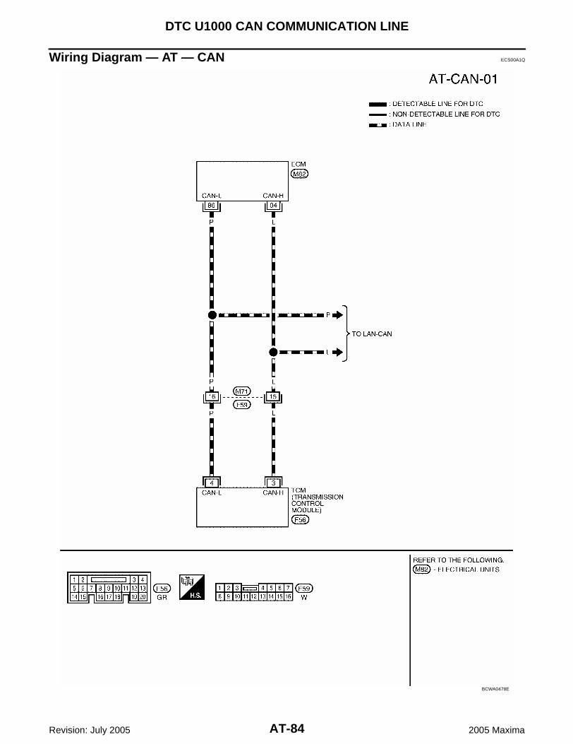
AT-84
DTC U1000 CAN COMMUNICATION LINE
Revision: July 2005 2005 Maxima
Wiring Diagram — AT — CAN ECS00A1Q
BCWA0478E

DTC U1000 CAN COMMUNICATION LINE
AT-85
D
E
F
G
H
I
J
K
L
M
A
B
AT
Revision: July 2005 2005 Maxima
TCM terminals and data are reference value.
Diagnostic Procedure ECS00A1R
1. CHECK CAN COMMUNICATION CIRCUIT
With CONSULT-II1. Turn ignition switch “ON” and start engine.2. Select “SELF-DIAG RESULTS” mode for "A/T" with CONSULT-
II.Is any malfunction of the "CAN COMM CIRCUIT" indicated?Yes >> Print out CONSULT-II screen, GO TO LAN section.
Refer to LAN-7, "CAN COMMUNICATION" .No >> INSPECTION END
TerminalWire color
Item Condition Data (Approx.)
3 L CAN H – –
4 P CAN L – –
SCIA2818E

AT-86
DTC P0500 VEHICLE SPEED SENSOR MTR
Revision: July 2005 2005 Maxima
DTC P0500 VEHICLE SPEED SENSOR MTR PFP:24814
Description ECS00A1S
The vehicle speed sensor·MTR signal is transmitted from unified meter and A/C amp. to TCM by CAN commu-nication line. The signal functions as an auxiliary device to the revolution sensor when it is malfunctioning. TheTCM will then use the vehicle speed sensor·MTR signal.
On Board Diagnosis Logic ECS00A1T
This is not an OBD-II self-diagnostic item. Diagnostic trouble code “VEH SPD SE/CIR-MTR” with CONSULT-II or 15th judgement flicker without
CONSULT-II is detected when TCM does not receive the proper vehicle speed sensor MTR signal (inputby CAN communication) from unified meter and A/C amp.
Possible Cause ECS00A1U
Harness or connectors(The signal circuit is open or shorted.)
Unified meter and A/C amp. ABS actuator and electric unit (control unit) Wheel sensor
DTC Confirmation Procedure ECS00A1V
CAUTION:Always drive vehicle at a safe speed.NOTE:If “DTC Confirmation Procedure” has been previously performed, always turn ignition switch “OFF”and wait at least 10 seconds before performing the next test.After the repair, perform the following procedure to confirm the malfunction is eliminated.
WITH CONSULT-II1. Turn ignition switch “ON” and select “DATA MONITOR” mode for
“A/T” with CONSULT-II.2. Start engine.3. Drive vehicle and maintain the following conditions for at least 5
consecutive seconds.VHCL/S SE-A/T: 30 km/h (17 MPH) or moreACCELE ANGLE: 10 % or less
4. If DTC is detected, go to AT-87, "Diagnostic Procedure" .
BCIA0030E

DTC P0500 VEHICLE SPEED SENSOR MTR
AT-87
D
E
F
G
H
I
J
K
L
M
A
B
AT
Revision: July 2005 2005 Maxima
Diagnostic Procedure ECS00A1W
1. CHECK INPUT SIGNALS
With CONSULT-II1. Start engine.2. Select “A/T” with “DATA MONITOR” mode in CONSULT-II.3. Drive vehicle, and then make sure that the values of “VHCL/S
SE-A/T” and “VHCL/S SE-MTR” are same.OK or NGOK >> GO TO 4.NG >> GO TO 2.
2. CHECK DTC WITH ABS ACTUATOR AND ELECTRIC UNIT (CONTROL UNIT)
Refer to BRC-12, "TROUBLE DIAGNOSIS" (with ABS), BRC-53, "TROUBLE DIAGNOSIS" (with TCS/ABS)or BRC-96, "TROUBLE DIAGNOSIS" (with VDC/TCS/ABS).OK or NGOK >> GO TO 3.NG >> If NG, recheck pin terminals for damage or loose connection with harness connector.
3. CHECK DTC WITH UNIFIED METER AND A/C AMP.
Refer to DI-5, "COMBINATION METERS" .OK or NGOK >> GO TO 4.NG >> If NG, recheck pin terminals for damage or loose connection with harness connector.
4. CHECK DTC
Perform “DTC Confirmation Procedure”. Refer to AT-86, "DTC Confirmation Procedure" .OK or NGOK >> INSPECTION ENDNG >> GO TO 5.
5. CHECK TCM
1. Check TCM input/output signal. Refer to AT-71, "TCM Input/Output Signal Reference Values" .2. If NG, recheck TCM pin terminals for damage or loose connection with harness connector.OK or NGOK >> INSPECTION ENDNG >> Repair or replace damaged parts.
SCIA2922E

AT-88
DTC P0613 TCM PROCESSOR
Revision: July 2005 2005 Maxima
DTC P0613 TCM PROCESSOR PFP:31036
Description ECS00A1X
The TCM consists of a microcomputer and connectors for signalinput and output and for power supply. The TCM controls the A/T.
On Board Diagnosis Logic ECS00A1Y
This is not an OBD-II self-diagnostic item. Diagnostic trouble code “TCM PROCESSOR” with CONSULT-II is detected when TCM processor is mal-
functioning.
Possible Cause ECS00A1Z
TCM
DTC Confirmation Procedure ECS00A20
NOTE:If “DTC Confirmation Procedure” has been previously performed, always turn ignition switch “OFF”and wait at least 10 seconds before performing the next test.After the repair, perform the following procedure to confirm the malfunction is eliminated.
WITH CONSULT-II1. Turn ignition switch “ON”. (Do not start engine.)2. Select “A/T” with “DATA MONITOR” mode in CONSULT-II.3. Start engine.4. Run engine for at least 2 consecutive seconds at idle speed.5. If DTC is detected, go to AT-89, "Diagnostic Procedure" .
SCIA2820E
BCIA0030E

DTC P0613 TCM PROCESSOR
AT-89
D
E
F
G
H
I
J
K
L
M
A
B
AT
Revision: July 2005 2005 Maxima
Diagnostic Procedure ECS00A21
1. CHECK DTC
With CONSULT-II1. Turn ignition switch “ON”. (Do not start engine.)2. Select “A/T” with “SELF-DIAG RESULTS” mode in CONSULT-II.3. Touch “ERASE”.4. Turn ignition switch “OFF” and wait at least 10 seconds.5. Perform DTC confirmation procedure, AT-88, "DTC Confirmation
Procedure" .Is the “TCM PROCESSOR” displayed again?YES >> Replace TCM. NO >> INSPECTION END
BCIA0031E

AT-90
DTC P0705 PARK/NEUTRAL POSITION SWITCH
Revision: July 2005 2005 Maxima
DTC P0705 PARK/NEUTRAL POSITION SWITCH PFP:32006
Description ECS00A22
The park/neutral position (PNP) switch includes a transmission position switch. The transmission range switch detects the selector lever position and sends a signal to the TCM. TCM judges the selector lever position by the park/neutral position (PNP) switch signal.
On Board Diagnosis Logic ECS00A23
This is an OBD-II self-diagnostic item. Diagnostic trouble code “PNP SW/CIRC” with CONSULT-II or P0705 without CONSULT-II is detected
when PNP switch signals input with impossible pattern.
Possible Cause ECS00A24
Harness or connectors[The park/neutral position (PNP) switch and TCM circuit is open or shorted.]
Park/neutral position (PNP) switch
DTC Confirmation Procedure ECS00A25
NOTE:If “DTC Confirmation Procedure” has been previously performed, always turn ignition switch “OFF”and wait at least 10 seconds before performing the next test.After the repair, perform the following procedure to confirm the malfunction is eliminated.
WITH CONSULT-II1. Turn ignition switch “ON”. (Do not start engine.)2. Select “A/T” with “DATA MONITOR” mode in CONSULT-II.3. Move selector lever to each position.
SLCT LVR POSI: “P”, “R”, “N” or “D” position4. Wait for at least 5 consecutive seconds at each position.5. If DTC is detected, go to AT-92, "Diagnostic Procedure" .
WITH GSTFollow the procedure “With CONSULT-II”.
Selector lever PNP switch A PNP switch B PNP switch C PNP switch PA PNP switch PN
P ON OFF OFF ON ON
R ON ON OFF OFF OFF
N OFF ON OFF ON ON
D OFF ON ON OFF OFF
BCIA0030E

DTC P0705 PARK/NEUTRAL POSITION SWITCH
AT-91
D
E
F
G
H
I
J
K
L
M
A
B
AT
Revision: July 2005 2005 Maxima
Wiring Diagram — AT — PNP/SW ECS00A26
BCWA0266E

AT-92
DTC P0705 PARK/NEUTRAL POSITION SWITCH
Revision: July 2005 2005 Maxima
TCM terminals and data are reference value. Measured between each terminal and ground.
Diagnostic Procedure ECS00A27
1. CHECK PNP SWITCH CIRCUIT
With CONSULT-II1. Turn ignition switch “ON”. (Do not start engine.)2. Select “DATA MONITOR” mode for “A/T” with CONSULT-II.3. Move selector lever to “P”, “N”, “R” and “D” position and check
the value of “PNP SW A”, “PNP SW B”, “PNP SW C”, “PNP SWPA” and “PNP SW PN”.
Without CONSULT-II1. Turn ignition switch “ON”. (Do not start engine.)2. Move selector lever to “P“, “R”, “N”, or “D” position and check
voltage between the TCM connector terminals and ground.
OK or NGOK >> GO TO 5.NG >> GO TO 2.
TerminalWire color
Item Condition Data (Approx.)
24 O/L PNP switch ASelector lever: “P” and “R” position 0V
Other than the above Battery voltage
31 BR PNP switch BSelector lever: “R”, “N”, “D” and manual mode position 0V
Other than the above Battery voltage
32 P/B PNP switch CSelector lever: “D” and manual mode position 0V
Other than the above Battery voltage
33 LG PNP switch PNSelector lever: “P” and “N” position Battery voltage
Other than the above 0V
43 V/W PNP switch PA Selector lever: “P” and “N” position 0V
Other than the above Battery voltage
Selector lever
“PNP SW A”
“PNP SW B”
“PNP SW C”
“PNP SW PA”
“PNP SW PN”
P ON OFF OFF ON ON
R ON ON OFF OFF OFF
N OFF ON OFF ON ON
D OFF ON ON OFF OFF
Selector lever
Connector No. F57
Terminal (Wire color)
24 (O/L) - Ground
31 (BR) - Ground
32 (P/B) - Ground
33 (LG) - Ground
43 (V/W) - Ground
P 0V Battery voltage
Battery voltage
Battery voltage
0V
R 0V 0V Battery voltage
0V Battery voltage
NBattery voltage
0V Battery voltage
Battery voltage
0V
DBattery voltage
0V 0V 0V Battery voltage
SCIA2823E
SCIA2826E

DTC P0705 PARK/NEUTRAL POSITION SWITCH
AT-93
D
E
F
G
H
I
J
K
L
M
A
B
AT
Revision: July 2005 2005 Maxima
2. CHECK PNP SWITCH POWER SOURCE CIRCUIT
1. Turn ignition switch “OFF”.2. Disconnect the PNP switch connector.3. Turn ignition switch “ON”. (Do not start engine.)4. Check voltage between PNP switch connector terminals 2, 5
and ground.
5. Turn ignition switch “OFF”.6. Check voltage between PNP switch connector terminals 2, 5
and ground.
7. If OK, check harness for short-circuit to ground or power source.OK or NGOK >> GO TO 3.NG >> Check the following. If any items are damaged, repair or replace damaged parts.
Harness for short or open between ignition switch and PNP switch Ignition switch and fuse
Refer to PG-4, "POWER SUPPLY ROUTING CIRCUIT" .
3. CHECK HARNESS BETWEEN TCM AND PNP SWITCH
1. Turn ignition switch “OFF”.2. Disconnect the TCM connector and PNP switch connector.3. Check continuity between TCM connector terminals 24, 31, 32,
43 and ground.
4. If OK, check the following.– Harness for short-circuit to ground or power source.– Open or short-circuit in the harness between unified meter and A/C auto amp. and TCM.OK or NGOK >> GO TO 5.NG >> GO TO 4.
Connector Terminal (Wire color) Voltage
F292 (O) - Ground
Battery voltage5 (G) - Ground
Connector Terminal (Wire color) Voltage
F292 (O) - Ground
0V5 (G) - Ground
SCIA2869E
ConnectorTerminal (Wire
color)Condition Continuity
F57
24 (O/L) - GroundSelector lever: “P” and “R” position Yes
Other than the above No
31 (BR) - Ground
Selector lever: “R”, “N”, “D” and manual mode position
Yes
Other than the above No
32 (P/B) - Ground
Selector lever: “D” and manual mode position
Yes
Other than the above No
43 (V/W) - GroundSelector lever: “P” and “N” position Yes
Other than the above No
SCIA2827E

AT-94
DTC P0705 PARK/NEUTRAL POSITION SWITCH
Revision: July 2005 2005 Maxima
4. DETECT MALFUNCTIONING ITEM
Check the following. Open or short-circuit in the harness between TCM and PNP switch A, B, C, PA. Open or short-circuit in the harness for ground of PNP switch. PNP switch. Refer to AT-94, "Component Inspection" .OK or NGOK >> GO TO 6.NG >> Repair or replace damaged parts.
5. CHECK DTC
Perform “DTC Confirmation Procedure”. Refer to AT-90, "DTC Confirmation Procedure" .OK or NGOK >> INSPECTION ENDNG >> GO TO 6.
6. CHECK TCM
1. Check TCM input/output signal. Refer to AT-71, "TCM Input/Output Signal Reference Values" .2. If NG, recheck TCM pin terminals for damage or loose connection with harness connector.OK or NGOK >> INSPECTION ENDNG >> Repair or replace damaged parts.
Component Inspection ECS00A28
PNP SWITCH1. Check continuity between PNP switch terminals while moving selector lever. Refer to the following table.
2. If NG, check again with control cable disconnected. (Refer to Step 1 above.)3. If OK on step 2, adjust control cable. Refer to AT-240, "Control Cable Adjustment" .4. If NG on step 2, remove park/neutral position (PNP) switch from A/T and check continuity of park/neutral
position (PNP) switch terminals. (Refer to step 1 above.)5. If OK on step 4, adjust park/neutral position (PNP) switch. Refer to AT-238, "Park/Neutral Position (PNP)
Switch Adjustment" .6. If NG on step 4, replace park/neutral position (PNP) switch.
SCIA2825E

DTC P0710 A/T FLUID TEMPERATURE SENSOR CIRCUIT
AT-95
D
E
F
G
H
I
J
K
L
M
A
B
AT
Revision: July 2005 2005 Maxima
DTC P0710 A/T FLUID TEMPERATURE SENSOR CIRCUIT PFP:31940
Description ECS00A29
The A/T fluid temperature sensor detects the A/T fluid temperature and sends a signal to the TCM.
On Board Diagnosis Logic ECS00A2A
This is an OBD-II self-diagnostic item. Diagnostic trouble code “ATF TEMP SEN/CIRC” with CONSULT-II or P0710 without CONSULT-II is
detected under the following conditions.– When normal voltage not applied to ATF temperature sensor due to open, short, and so on.– When during running, the ATF temperature sensor signal voltage is excessively high or low.
Possible Cause ECS00A2B
Harness or connectors(The sensor circuit is open or shorted.)
A/T fluid temperature sensor
DTC Confirmation Procedure ECS00A2C
NOTE:If “DTC Confirmation Procedure” has been previously performed, always turn ignition switch “OFF”and wait at least 10 seconds before performing the next test.After the repair, perform the following procedure to confirm the malfunction is eliminated.
WITH CONSULT-II1. Turn ignition switch “ON”. (Do not start engine.)2. Select “A/T” with “DATA MONITOR” mode in CONSULT-II.3. Start engine.4. Warm up engine so that engine coolant temperature is more
than 50°C (122°F).COOLAN TEMP: More than 50°C (122°F)
5. Maintain the following conditions for at least 16 minutes (Total).(It is not necessary to drive vehicle.)COOLAN TEMP: More than 50°C (122°F)SLCT LVR POSI: “D” position
6. If DTC is detected, go to AT-97, "Diagnostic Procedure" .
WITH GSTFollow the procedure “With CONSULT-II”.
BCIA0030E

AT-96
DTC P0710 A/T FLUID TEMPERATURE SENSOR CIRCUIT
Revision: July 2005 2005 Maxima
Wiring Diagram — AT — FTS ECS00A2D
BCWA0267E

DTC P0710 A/T FLUID TEMPERATURE SENSOR CIRCUIT
AT-97
D
E
F
G
H
I
J
K
L
M
A
B
AT
Revision: July 2005 2005 Maxima
TCM terminals and data are reference value. Measured between each terminal and ground.
Diagnostic Procedure ECS00A2E
1. CHECK FLUID TEMPERATURE SENSOR SIGNAL
With CONSULT-II1. Start engine.2. Select “A/T” with “DATA MONITOR” mode in CONSULT-II.3. Read out the value of “FLUID TEMP SE”.
Without CONSULT-II1. Start engine.2. Check voltage between TCM connector terminals 41 and 42
while warming up A/T. Refer to AT-96, "Wiring Diagram — AT —FTS" .
3. Turn ignition switch “OFF”.4. Disconnect the TCM connector.5. Check if there is continuity between the connector terminal and ground.OK or NGOK >> GO TO 6.NG >> GO TO 2.
TerminalWire color
Item ConditionData (Approx.)
41 R/YFluid temperature sensor
When ATF temperature 0°C (32°F) 4.0V 9.8 kΩ
When ATF temperature 20°C (68°F) 3.0V 4.2 kΩ
When ATF temperature 80°C (176°F) 0.8V .54 kΩ
When ATF temperature 100°C (212°F) 0.5V .31 kΩ
42 LGFluid temperature sensor ground
Always 0V
Item name Condition Display value (Approx.)
Fluid temperature sensor
0°C (32°F) 4.0V
20°C (68°F) 3.0V
80°C (176°F) 0.8V
100°C (212°F) 0.5V
SCIA2870E
Connector Terminal (Wire color) Temperature Voltage (Approx.)
F57 41 (R/Y) - 42 (LG) (ground)
0°C (32°F) 4.0V
20°C (68°F) 3.0V
80°C (176°F) 0.8V
100°C (212°F) 0.5V
SCIA2871E
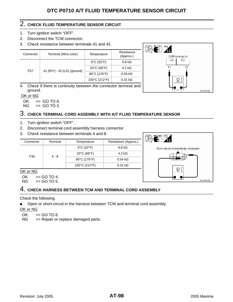
AT-98
DTC P0710 A/T FLUID TEMPERATURE SENSOR CIRCUIT
Revision: July 2005 2005 Maxima
2. CHECK FLUID TEMPERATURE SENSOR CIRCUIT
1. Turn ignition switch “OFF”.2. Disconnect the TCM connector.3. Check resistance between terminals 41 and 42.
4. Check if there is continuity between the connector terminal andground.
OK or NG OK >> GO TO 6. NG >> GO TO 3.
3. CHECK TERMINAL CORD ASSEMBLY WITH A/T FLUID TEMPERATURE SENSOR
1. Turn ignition switch “OFF”.2. Disconnect terminal cord assembly harness connector.3. Check resistance between terminals 4 and 8.
OK or NGOK >> GO TO 4.NG >> GO TO 5.
4. CHECK HARNESS BETWEEN TCM AND TERMINAL CORD ASSEMBLY
Check the following. Open or short-circuit in the harness between TCM and terminal cord assembly.OK or NGOK >> GO TO 6.NG >> Repair or replace damaged parts.
Connector Terminal (Wire color) Temperature Resistance
(Approx.)
F57 41 (R/Y) - 42 (LG) (ground)
0°C (32°F) 9.8 kΩ
20°C (68°F) 4.2 kΩ
80°C (176°F) 0.54 kΩ
100°C (212°F) 0.31 kΩ
SCIA2872E
Connector Terminal Temperature Resistance (Approx.)
F30 4 - 8
0°C (32°F) 9.8 kΩ
20°C (68°F) 4.2 kΩ
80°C (176°F) 0.54 kΩ
100°C (212°F) 0.31 kΩ
SCIA2873E

DTC P0710 A/T FLUID TEMPERATURE SENSOR CIRCUIT
AT-99
D
E
F
G
H
I
J
K
L
M
A
B
AT
Revision: July 2005 2005 Maxima
5. CHECK A/T FLUID TEMPERATURE SENSOR
1. Remove side cover. Refer to AT-241, "Side cover" .2. Disconnect A/T fluid temperature sensor.3. Check resistance between terminals 4 and 8.
OK or NGOK >> GO TO 6.NG >> Repair or replace transmission wire. Refer to AT-241,
"Terminal cord assembly" .
6. CHECK DTC
Perform “DTC Confirmation Procedure”. Refer to AT-95, "DTC Confirmation Procedure" .OK or NGOK >> INSPECTION ENDNG >> GO TO 7.
7. CHECK TCM
1. Check TCM input/output signal. Refer to AT-71, "TCM Input/Output Signal Reference Values" .2. If NG, recheck TCM pin terminals for damage or loose connection with harness connector.OK or NGOK >> INSPECTION ENDNG >> Repair or replace damaged parts.
Component Inspection ECS00A2F
A/T FLUID TEMPERATURE SENSOR1. Remove side cover. Refer to AT-241, "Side cover" .2. Disconnect A/T fluid temperature sensor.3. Check resistance between terminals 4 and 8.
4. If NG, repair and replace transmission wire. Refer to AT-241,"Terminal cord assembly" .
Connector Terminal Temperature Resistance
F30 4 - 810°C (50°F) 5.80 - 7.09kΩ
110°C (230°F) 0.23 - 0.26kΩ
WCIA0448E
Connector Terminal Temperature Resistance
F30 4 - 810°C (50°F) 5.80 - 7.09kΩ
110°C (230°F) 0.23 - 0.26kΩ
WCIA0448E

AT-100
DTC P0711 FLUID TEMPERATURE SENSOR PERFORMANCE
Revision: July 2005 2005 Maxima
DTC P0711 FLUID TEMPERATURE SENSOR PERFORMANCE PFP:31940
Description ECS00A2G
The A/T fluid temperature sensor detects the A/T fluid temperature and sends a signal to the TCM.
On Board Diagnosis Logic ECS00A2H
This is an OBD-II self-diagnostic item. Diagnostic trouble code “FLUID TEMP SEN” with CONSULT-II or P0711 without CONSULT-II is detected
when ATF temperature signal does not change.
Possible Cause ECS00A2I
Harness or connectors(The sensor circuit is open or shorted.)
A/T fluid temperature sensor
DTC Confirmation Procedure ECS00A2J
CAUTION:Always drive vehicle at a safe speed.NOTE:If “DTC Confirmation Procedure” has been previously performed, always turn ignition switch “OFF”and wait at least 10 seconds before performing the next test.After the repair, perform the following procedure to confirm the malfunction is eliminated.
WITH CONSULT-II1. Turn ignition switch “ON”. (Do not start engine.)2. Select “A/T” with “DATA MONITOR” mode in CONSULT-II.3. Start engine.4. Drive vehicle and maintain the following conditions for at least
15 minutes (Total). (It is not necessary to maintain continuously.)VHCL SPEED SE-A/T: 40 km/h (25 MPH) or moreSLCT LVR POSI: “D” position
5. If DTC is detected, go to AT-102, "Diagnostic Procedure" .
WITH GSTFollow the procedure “With CONSULT-II”.
BCIA0030E

DTC P0711 FLUID TEMPERATURE SENSOR PERFORMANCE
AT-101
D
E
F
G
H
I
J
K
L
M
A
B
AT
Revision: July 2005 2005 Maxima
Wiring Diagram — AT — FTSP ECS00A2K
BCWA0268E

AT-102
DTC P0711 FLUID TEMPERATURE SENSOR PERFORMANCE
Revision: July 2005 2005 Maxima
TCM terminals and data are reference value. Measured between each terminal and ground.
Diagnostic Procedure ECS00A2L
1. CHECK FLUID TEMPERATURE SENSOR SIGNAL
With CONSULT-II1. Start engine.2. Select “A/T” with “DATA MONITOR” mode in CONSULT-II.3. Read out the value of “FLUID TEMP SE”.
Without CONSULT-II1. Start engine.2. Check voltage between TCM connector terminals 41 and 42
while warming up A/T. Refer to AT-101, "Wiring Diagram — AT— FTSP" .
3. Turn ignition switch “OFF”.4. Disconnect the TCM connector.5. Check if there is continuity between the connector terminal and ground.OK or NGOK >> GO TO 6.NG >> GO TO 2.
TerminalWire color
Item Condition Data (Approx.)
41 R/YFluid temperature sensor
When ATF temperature 0°C (32°F) 4.0V 9.8 kΩ
When ATF temperature 20°C (68°F) 3.0V 4.2 kΩ
When ATF temperature 80°C (176°F) 0.8V .54 kΩ
When ATF temperature 100°C (212°F) 0.5V .31 kΩ
42 LGFluid temperature sensor ground
Always 0V
Item name Condition Display value (Approx.)
Fluid temperature sensor
0°C (32°F) 4.0V
20°C (68°F) 3.0V
80°C (176°F) 0.8V
100°C (212°F) 0.5V
SCIA2870E
Connector Terminal (Wire color) Temperature Voltage (Approx.)
F57 41 (R/Y) - 42 (LG) (ground)
0°C (32°F) 4.0V
20°C (68°F) 3.0V
80°C (176°F) 0.8V
100°C (212°F) 0.5V
SCIA2871E

DTC P0711 FLUID TEMPERATURE SENSOR PERFORMANCE
AT-103
D
E
F
G
H
I
J
K
L
M
A
B
AT
Revision: July 2005 2005 Maxima
2. CHECK FLUID TEMPERATURE SENSOR CIRCUIT
1. Turn ignition switch “OFF”.2. Disconnect the TCM connector.3. Check resistance between terminals 41 and 42.
4. Check if there is continuity between the connector terminal andground.
OK or NG OK >> GO TO 6. NG >> GO TO 3.
3. CHECK TERMINAL CORD ASSEMBLY WITH A/T FLUID TEMPERATURE SENSOR
1. Turn ignition switch “OFF”.2. Disconnect terminal cord assembly harness connector.3. Check resistance between terminals 4 and 8.
4. Reinstall any part removed.OK or NGOK >> GO TO 4.NG >> GO TO 5.
4. CHECK HARNESS BETWEEN TCM AND TERMINAL CORD ASSEMBLY
Check the following. Open or short-circuit in the harness between TCM and terminal cord assembly.OK or NGOK >> GO TO 6.NG >> Repair or replace damaged parts.
Connector Terminal (Wire color) Temperature Resistance
(Approx.)
F57 41 (R/Y) - 42 (LG) (ground)
0°C (32°F) 9.8 kΩ
20°C (68°F) 4.2 kΩ
80°C (176°F) 0.54 kΩ
100°C (212°F) 0.31 kΩ
SCIA2872E
Connector Terminal Temperature Resistance (Approx.)
F30 4 - 8
0°C (32°F) 9.8 kΩ
20°C (68°F) 4.2 kΩ
80°C (176°F) 0.54 kΩ
100°C (212°F) 0.31 kΩ
SCIA2873E

AT-104
DTC P0711 FLUID TEMPERATURE SENSOR PERFORMANCE
Revision: July 2005 2005 Maxima
5. CHECK A/T FLUID TEMPERATURE SENSOR
1. Remove side cover. Refer to AT-241, "Side cover" .2. Disconnect A/T fluid temperature sensor.3. Check resistance between terminals 4 and 8.
OK or NGOK >> GO TO 6.NG >> Repair or replace transmission wire. Refer to AT-241,
"Terminal cord assembly" .
6. CHECK DTC
Perform “DTC Confirmation Procedure”. Refer to AT-100, "DTC Confirmation Procedure" .OK or NGOK >> INSPECTION ENDNG >> GO TO 7.
7. CHECK TCM
1. Check TCM input/output signal. Refer to AT-71, "TCM Input/Output Signal Reference Values" .2. If NG, recheck TCM pin terminals for damage or loose connection with harness connector.OK or NGOK >> INSPECTION ENDNG >> Repair or replace damaged parts.
Component Inspection ECS00A2M
A/T FLUID TEMPERATURE SENSOR1. Remove side cover. Refer to AT-241, "Side cover" .2. Disconnect A/T fluid temperature sensor.3. Check resistance between terminals 4 and 8.
4. If NG, repair or replace transmission wire. Refer to AT-241, "Ter-minal cord assembly" .
Connector Terminal) Temperature Resistance
F30 4 - 810°C (50°F) 5.80 - 7.09kΩ
110°C (230°F) 0.23 - 0.26kΩ
WCIA0448E
Connector Terminal) Temperature Resistance
F30 4 - 810°C (50°F) 5.80 - 7.09kΩ
110°C (230°F) 0.23 - 0.26kΩ
WCIA0448E

DTC P0717 TURBINE REVOLUTION SENSOR CIRCUIT
AT-105
D
E
F
G
H
I
J
K
L
M
A
B
AT
Revision: July 2005 2005 Maxima
DTC P0717 TURBINE REVOLUTION SENSOR CIRCUIT PFP:31935
Description ECS00A2N
The turbine revolution sensor detects forward clutch drum rpm(revolutions per minute). It is located on the input side of theautomatic transaxle. The revolution sensor is located on the out-put side of the automatic transaxle. With the two sensors, inputand output rpms are accurately detected. The result is optimalshift timing during deceleration and improved shifting.
Hall IC is installed in turbine revolution sensor, it itself handles inpulse of rectangular wave signal and transmits it to TCM due tohall effect. TCM recognizes the pulse with input rpm speed. Sizeof output doesn't depend on a rotation number and is fixed.
On Board Diagnosis Logic ECS00A2O
This is an OBD-II self-diagnostic item. Diagnostic trouble code “TURBINE SENSOR” with CONSULT-II or P0717 without CONSULT-II is
detected under the following conditions.– When signal from turbine revolution sensor does not input due to open, short, and so on.– When unexpected signal input during running.
Possible Cause ECS00A2P
Harness or connectors(The sensor circuit is open or shorted.)
Turbine revolution sensor
DTC Confirmation Procedure ECS00A2Q
CAUTION:Always drive vehicle at a safe speed.NOTE:If “DTC Confirmation Procedure” has been previously performed, always turn ignition switch “OFF”and wait at least 10 seconds before performing the next test.After the repair, perform the following procedure to confirm the malfunction is eliminated.
WITH CONSULT-II1. Turn ignition switch “ON”. (Do not start engine.)2. Select “DATA MONITOR” mode for “A/T” with CONSULT-II.3. Start engine.4. Drive vehicle and maintain the following conditions for at least 1
consecutive minute.FLUID TEMP: More than 20°C (68°F)VHCL/S SE-A/T: 70 km/h (43 MPH) or moreSLCT LVR POSI: “D” positionGEAR: Except 1st position
5. If DTC is detected, go to AT-107, "Diagnostic Procedure" .
WITH GSTFollow the procedure “With CONSULT-II”.
SCIA2830E
BCIA0030E

AT-106
DTC P0717 TURBINE REVOLUTION SENSOR CIRCUIT
Revision: July 2005 2005 Maxima
Wiring Diagram — AT — TRSC ECS00A2R
BCWA0269E
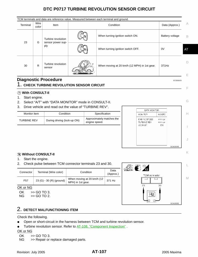
DTC P0717 TURBINE REVOLUTION SENSOR CIRCUIT
AT-107
D
E
F
G
H
I
J
K
L
M
A
B
AT
Revision: July 2005 2005 Maxima
TCM terminals and data are reference value. Measured between each terminal and ground.
Diagnostic Procedure ECS00A2S
1. CHECK TURBINE REVOLUTION SENSOR CIRCUIT
With CONSULT-II1. Start engine.2. Select “A/T” with “DATA MONITOR” mode in CONSULT-II.3. Drive vehicle and read out the value of “TURBINE REV”.
Without CONSULT-II1. Start the engine.2. Check pulse between TCM connector terminals 23 and 30.
OK or NGOK >> GO TO 3.NG >> GO TO 2.
2. DETECT MALFUNCTIONING ITEM
Check the following. Open or short-circuit in the harness between TCM and turbine revolution sensor. Turbine revolution sensor. Refer to AT-108, "Component Inspection" .OK or NGOK >> GO TO 3.NG >> Repair or replace damaged parts.
TerminalWire color
Item Condition Data (Approx.)
23 GTurbine revolution sensor power sup-ply
When turning ignition switch ON. Battery voltage
When turning ignition switch OFF. 0V
30 RTurbine revolution sensor
When moving at 20 km/h (12 MPH) in 1st gear. 371Hz
Monitor item Condition Specification
TURBINE REV During driving (lock-up ON) Approximately matches the engine speed.
SCIA2924E
Connector Terminal (Wire color) ConditionData
(Approx.)
F57 23 (G) - 30 (R) (ground)When moving at 20 km/h (12 MPH) in 1st gear.
371 Hz
SCIA2925E

AT-108
DTC P0717 TURBINE REVOLUTION SENSOR CIRCUIT
Revision: July 2005 2005 Maxima
3. CHECK DTC
Perform “DTC Confirmation Procedure”. Refer to AT-105, "DTC Confirmation Procedure" .OK or NGOK >> INSPECTION ENDNG >> GO TO 4.
4. CHECK TCM
1. Check TCM input/output signal. Refer to AT-71, "TCM Input/Output Signal Reference Values" .2. If NG, recheck TCM pin terminals for damage or loose connection with harness connector.OK or NGOK >> INSPECTION ENDNG >> Repair or replace damaged parts.
Component Inspection ECS00A2T
TURBINE REVOLUTION SENSOR1. Remove turbine revolution sensor.2. Connect 12V power supply and 100 Ω resistance to the termi-
nal. (Do not mistake polarity)3. Inspect the voltage of HIGH and LOW signal by shaking mag-
netic body from side to side at turbine revolution sensor tip [gapis within 5 mm (0.20 in)].CAUTION:Make sure to shake direction from bolt hole to sensor-selfwhen shaking magnetic body. If not, voltage value cannotchange.
4. If NG, replace turbine revolution sensor.
Signal Voltage (Approx.)
HIGH 1.2 - 1.6V
LOW 0.4 - 0.8V
SCIA2927E

DTC P0722 VEHICLE SPEED SENSOR A/T (REVOLUTION SENSOR) CIRCUIT
AT-109
D
E
F
G
H
I
J
K
L
M
A
B
AT
Revision: July 2005 2005 Maxima
DTC P0722 VEHICLE SPEED SENSOR A/T (REVOLUTION SENSOR) CIRCUITPFP:31935
Description ECS00A2U
The revolution sensor detects the revolution of the idler gearparking pawl lock gear and emits a pulse signal. The pulse sig-nal is sent to the TCM which converts it into vehicle speed.
Hall IC is installed in revolution sensor, it itself handles in pulseof rectangular wave signal and transmits it to TCM due to halleffect. TCM recognizes the pulse with vehicle speed. Size ofoutput doesn't depend on a rotation number and is fixed.
On Board Diagnosis Logic ECS00A2V
This is an OBD-II self-diagnostic item. Diagnostic trouble code “VHCL SPEED SEN-A/T” with CONSULT-II or P0722 without CONSULT-II is
detected under the following conditions.– When signal from revolution sensor does not input due to open, short, and so on.– When unexpected signal input during running.
Possible Cause ECS00A2W
Harness or connectors(The sensor circuit is open or shorted.)
Revolution sensor
DTC Confirmation Procedure ECS00A2X
CAUTION: Always drive vehicle at a safe speed. Be careful not to rev engine into the red zone on the tachometer.NOTE:If “DTC Confirmation Procedure” has been previously performed, always turn ignition switch “OFF”and wait at least 10 seconds before performing the next test.After the repair, perform the following procedure to confirm the malfunction is eliminated.
WITH CONSULT-II1. Turn ignition switch “ON”. (Do not start engine.)2. Select “DATA MONITOR” mode for “A/T” with CONSULT-II.3. Start engine.4. Drive vehicle and check for an increase of “VHCL/S SE-A/T”
value in response to “VHCL/S SE-MTR” value.If the check result is NG, go to AT-111, "Diagnostic Procedure" .If the check result is OK, go to following step.
5. Maintain the following conditions for at least 2 consecutive min-utes.FLUID TEMP: More than 20°C (68°F)VHCL/S SE-A/T: 70 km/h (43 MPH) or moreSLCT LVR POSI: “D” positionIf the check result is NG, go to AT-111, "Diagnostic Procedure" .
WITH GSTFollow the procedure “With CONSULT-II”.
SCIA2830E
BCIA0030E

AT-110
DTC P0722 VEHICLE SPEED SENSOR A/T (REVOLUTION SENSOR) CIRCUIT
Revision: July 2005 2005 Maxima
Wiring Diagram — AT — VSSATC ECS00A2Y
BCWA0270E

DTC P0722 VEHICLE SPEED SENSOR A/T (REVOLUTION SENSOR) CIRCUIT
AT-111
D
E
F
G
H
I
J
K
L
M
A
B
AT
Revision: July 2005 2005 Maxima
TCM terminals and data are reference value. Measured between each terminal and ground.
Diagnostic Procedure ECS00A2Z
1. CHECK REVOLUTION SENSOR CIRCUIT
With CONSULT-II1. Start engine.2. Select “A/T” with “DATA MONITOR” mode in CONSULT-II.3. Drive vehicle and read out the value of “VHCL/S SE-AT”.
Without CONSULT-II1. Start the engine.2. Check pulse between TCM connector terminals 22 and 29.
OK or NGOK >> GO TO 3.NG >> GO TO 2.
2. DETECT MALFUNCTIONING ITEM
Check the following. Open or short-circuit in the harness between TCM and revolution sensor. Revolution sensor. Refer to AT-112, "Component Inspection" .OK or NGOK >> GO TO 3.NG >> Repair or replace damaged parts.
TerminalWire color
Item Condition Data (Approx.)
22 LRevolution sensor power supply
When turning ignition switch ON. Battery voltage
When turning ignition switch OFF. 0V
29 B/W Revolution sensor When moving at 20 km/h (12 MPH) in 1st gear. 119Hz
Monitor item Condition Specification
VHCL/S SE-AT During drivingApproximately matches the speedometer reading.
SCIA2922E
Connector Terminal (Wire color) ConditionData
(Approx.)
F57 22 (L) - 29 (B/W) (ground)When moving at 20 km/h (12 MPH) in 1st gear.
119 Hz
SCIA2928E

AT-112
DTC P0722 VEHICLE SPEED SENSOR A/T (REVOLUTION SENSOR) CIRCUIT
Revision: July 2005 2005 Maxima
3. CHECK DTC
Perform “DTC Confirmation Procedure”. Refer to AT-109, "DTC Confirmation Procedure" .OK or NGOK >> INSPECTION ENDNG >> GO TO 4.
4. CHECK TCM
1. Check TCM input/output signal. Refer to AT-71, "TCM Input/Output Signal Reference Values" .2. If NG, recheck TCM pin terminals for damage or loose connection with harness connector.OK or NGOK >> INSPECTION ENDNG >> Repair or replace damaged parts.
Component Inspection ECS00A30
REVOLUTION SENSOR1. Remove revolution sensor.2. Connect 12V power supply and 100 Ω resistance to the termi-
nal. (Do not mistake polarity)3. Inspect the voltage of HIGH and LOW signal by shaking mag-
netic body from side to side at revolution sensor tip [gap is within5mm (0.20 in)].CAUTION:Make sure to shake direction from bolt hole to sensor-selfwhen shaking magnetic body. If not, voltage value cannotchange.
4. If NG, replace revolution sensor.
Signal Voltage (Approx.)
HIGH 1.2 - 1.6V
LOW 0.4 - 0.8V
SCIA2927E

DTC P0726 ENGINE SPEED INPUT CIRCUIT PERFORMANCE
AT-113
D
E
F
G
H
I
J
K
L
M
A
B
AT
Revision: July 2005 2005 Maxima
DTC P0726 ENGINE SPEED INPUT CIRCUIT PERFORMANCE PFP:31036
Description ECS00A31
The engine speed signal is sent from the ECM to the TCM.
On Board Diagnosis Logic ECS00A32
This is not an OBD-II self-diagnostic item. Diagnostic trouble code “ENG SPD INP PERFOR” with CONSULT-II or 14th judgement flicker without
CONSULT-II is detected when malfunction is detected in engine speed signal, actual engine torque signalor torque reduction signal that is output from ECM through CAN communication.
Possible Cause ECS00A33
Harness or connectors(The signal circuit is open or shorted.)
ECM
DTC Confirmation Procedure ECS00A34
CAUTION:Always drive vehicle at a safe speed.NOTE:If “DTC Confirmation Procedure” has been previously performed, always turn ignition switch “OFF”and wait at least 10 seconds before performing the next test.After the repair, perform the following procedure to confirm the malfunction is eliminated.
WITH CONSULT-II1. Turn ignition switch “ON” and select “A/T” with “DATA MONI-
TOR” mode in CONSULT-II.2. Start engine.3. Drive vehicle and maintain the following conditions for at least
10 consecutive seconds.VHCL/S SE-A/T: 10 km/h (6 MPH) or moreACCELE ANGLE: More than 10 %SLCT LVR POSI: “D” position
4. If DTC is detected, go to AT-113, "Diagnostic Procedure" .
Diagnostic Procedure ECS00A35
1. CHECK DTC WITH ECM
With CONSULT-II1. Turn ignition switch “ON”. (Do not start engine.)2. Select “ENGINE” with “SELF-DIAG RESULTS” mode in CON-
SULT-II. Refer to AT-74, "CONSULT-II Function (TCM)" .OK or NGOK >> GO TO 2.NG >> Check the DTC detected item, go to AT-5, "INDEX FOR
DTC" . If CAN communication line is detected, go to AT-83,
"DTC U1000 CAN COMMUNICATION LINE" .
BCIA0030E
BCIA0030E

AT-114
DTC P0726 ENGINE SPEED INPUT CIRCUIT PERFORMANCE
Revision: July 2005 2005 Maxima
2. CHECK DTC WITH TCM
With CONSULT-II1. Start engine.2. Select “A/T” with “DATA MONITOR” mode in CONSULT-II.3. While monitoring “ENGINE SPEED”, check for engine speed
change corresponding to “ACCELE ANGLE”.OK or NGOK >> GO TO 3.NG >> Check the ignition signal circuit.
Refer to EC-666, "IGNITION SIGNAL" .
3. CHECK DTC
Perform “DTC Confirmation Procedure”. Refer to AT-113, "DTC Confirmation Procedure" .OK or NGOK >> INSPECTION ENDNG >> GO TO 4.
4. CHECK TCM
1. Check TCM input/output signal. Refer to AT-71, "TCM Input/Output Signal Reference Values" .2. If NG, recheck TCM pin terminals for damage or loose connection with harness connector.OK or NGOK >> INSPECTION ENDNG >> Repair or replace damaged parts.
SCIA2929E

DTC P0731 A/T 1ST GEAR FUNCTION
AT-115
D
E
F
G
H
I
J
K
L
M
A
B
AT
Revision: July 2005 2005 Maxima
DTC P0731 A/T 1ST GEAR FUNCTION PFP:31940
Description ECS00A36
This malfunction will not be detected while the A/T CHECK indicator lamp is indicating another self-diag-nosis malfunction.
This malfunction is detected when the A/T does not shift into first gear position as instructed by the TCM.This is not caused by electrical malfunction (circuits open or shorted) but by mechanical malfunction suchas control valve sticking, improper solenoid valve operation, etc.
On Board Diagnosis Logic ECS00A37
This is an OBD-II self-diagnostic item. Diagnostic trouble code “A/T 1ST GR FNCTN” with CONSULT-II or P0731 without CONSULT-II is
detected when A/T cannot be shifted to the 1st gear position even if electrical circuit is good.
Possible Cause ECS00A38
Shift solenoid valve A(Off stick.)
2nd brake 2nd coast brake One-way clutch No.1 One-way clutch No.2 Hydraulic control circuit
DTC Confirmation Procedure ECS00A39
CAUTION: Always drive vehicle at a safe speed. Be careful not to rev engine into the red zone on the tachometer.NOTE:If “DTC Confirmation Procedure” has been previously performed, always turn ignition switch “OFF”and wait at least 10 seconds before performing the next test.After the repair, perform the following procedure to confirm the malfunction is eliminated.
WITH CONSULT-II1. Start engine and select “A/T” with “DATA MONITOR” mode in
CONSULT-II.2. Make sure that ATF temperature is within the range below.
FLUID TEMP: More than 20°C (68°F) If out of range, drive the vehicle to warm up the fluid.
3. Accelerate vehicle to maintain the following conditions for atleast 12 consecutive seconds.SLCT LVR POSI: “D” positionGEAR: 1st position[Vehicle speed and accelerator angle: 1st gear positionretainable condition. (Refer to AT-312, "VEHICLE SPEEDWHEN SHIFTING GEARS" .)]Driving location: Driving the vehicle uphill (increased engine load) will help maintain the drivingconditions required for this test.
4. If DTC is detected, go to AT-117, "Diagnostic Procedure" .
WITH GSTFollow the procedure “With CONSULT-II”.
Gear positionShift solenoid valve
A B C D E
1stD ON (Closed) ON (Open) ON (Open) OFF (Open) OFF (Closed)
M1 ON (Closed) ON (Open) ON (Open) OFF (Open) ON (Open)
BCIA0030E

AT-116
DTC P0731 A/T 1ST GEAR FUNCTION
Revision: July 2005 2005 Maxima
Wiring Diagram — AT — 1STSIG ECS00A3A
BCWA0271E

DTC P0731 A/T 1ST GEAR FUNCTION
AT-117
D
E
F
G
H
I
J
K
L
M
A
B
AT
Revision: July 2005 2005 Maxima
TCM terminal and data are reference value. Measured between each terminal and ground.
Diagnostic Procedure ECS00A3B
1. CHECK SHIFT SOLENOID VALVE A CIRCUIT
Perform “Diagnostic Procedure” for DTC P0750. Refer to AT-151, "Diagnostic Procedure" .OK or NGOK >> GO TO 2.NG >> Repair or replace damaged parts.
2. CHECK MALFUNCTIONING ITEM
1. Control valve assembly. Refer to AT-241, "Control Valve Assembly" .2. Disassembly A/T. Refer to AT-252, "DISASSEMBLY" .3. Check the following item:– 2nd brake. Refer to AT-272, "Oil Pump, 2nd Coast Brake & 2nd Brake" .– 2nd coast brake. Refer to AT-272, "Oil Pump, 2nd Coast Brake & 2nd Brake" , AT-278, "One-Way Clutch
Outer Race Sub Assembly & 2nd Coast Brake Hub & One-Way Clutch No.1" .– One-way clutch No.1. Refer to AT-278, "One-Way Clutch Outer Race Sub Assembly & 2nd Coast Brake
Hub & One-Way Clutch No.1" .– One-way clutch No.2. Refer to AT-252, "DISASSEMBLY" . OK or NG OK >> GO TO 3. NG >> Repair or replace damaged parts.
3. CHECK DTC
Perform “DTC Confirmation Procedure”. Refer to AT-115, "DTC Confirmation Procedure" .OK or NGOK >> INSPECTION ENDNG >> Replace control valve assembly. Refer to AT-241, "Control Valve Assembly" .
TerminalWire color
Item Condition Data (Approx.)
46 W/GShift solenoid valve A
When shift solenoid valve A operates.(When driving in 1st gear.)
Battery voltage
When shift solenoid valve A does not operate. 0V

AT-118
DTC P0732 A/T 2ND GEAR FUNCTION
Revision: July 2005 2005 Maxima
DTC P0732 A/T 2ND GEAR FUNCTION PFP:31940
Description ECS00A3C
This malfunction will not be detected while the A/T CHECK indicator lamp is indicating another self-diag-nosis malfunction.
This malfunction is detected when the A/T does not shift into second gear position as instructed by theTCM. This is not caused by electrical malfunction (circuits open or shorted) but by mechanical malfunctionsuch as control valve sticking, improper solenoid valve operation, etc.
On Board Diagnosis Logic ECS00A3D
This is an OBD-II self-diagnostic item. Diagnostic trouble code “A/T 2ND GR FNCTN” with CONSULT-II or P0732 without CONSULT-II is
detected when A/T cannot be shifted to the 2nd gear position even if electrical circuit is good.
Possible Cause ECS00A3E
Shift solenoid valve A(On stick.)
Shift solenoid valve B(On stick.)
Shift solenoid valve C(Off stick.)
Shift solenoid valve D(On stick.)
Pressure control solenoid valve A(On stick.)
Pressure control solenoid valve C(On stick.)
U/D brake 2nd coast brake 2nd brake One-way clutch No.1 One-way clutch No.2 B5 brake Hydraulic control circuit
DTC Confirmation Procedure ECS00A3F
CAUTION: Always drive vehicle at a safe speed. Be careful not to rev engine into the red zone on the tachometer.NOTE:If “DTC Confirmation Procedure” has been previously performed, always turn ignition switch “OFF”and wait at least 10 seconds before performing the next test.After the repair, perform the following procedure to confirm the malfunction is eliminated.
Gear positionShift solenoid valve
A B C D E
2ndD OFF (Open) OFF (Closed) ON (Open) OFF (Open) OFF (Closed)
M2 OFF (Open) OFF (Closed) ON (Open) OFF (Open) OFF (Closed)

DTC P0732 A/T 2ND GEAR FUNCTION
AT-119
D
E
F
G
H
I
J
K
L
M
A
B
AT
Revision: July 2005 2005 Maxima
WITH CONSULT-II1. Start engine and select “A/T” with “DATA MONITOR” mode in
CONSULT-II.2. Make sure that ATF temperature is within the range below.
FLUID TEMP: More than 20°C (68°F)If out of range, drive the vehicle to warm up the fluid.
3. Accelerate vehicle to maintain the following conditions for atleast 12 consecutive seconds.SLCT LVR POSI: “D” positionGEAR: 2nd position[Vehicle speed and accelerator angle: 2nd gear positionretainable condition. (Refer to AT-312, "VEHICLE SPEEDWHEN SHIFTING GEARS" .)]Driving location: Driving the vehicle uphill (increased engine load) will help maintain the drivingconditions required for this test.
4. If DTC is detected, go to AT-122, "Diagnostic Procedure" .
WITH GSTFollow the procedure “With CONSULT-II”.
BCIA0030E
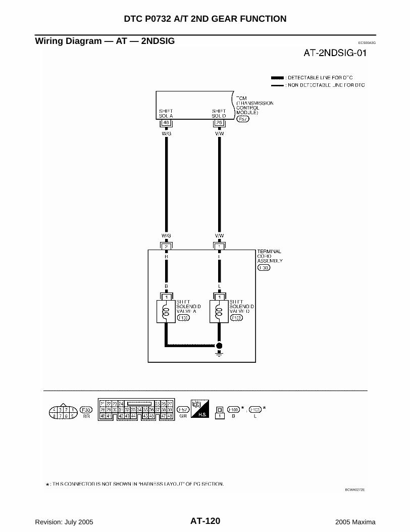
AT-120
DTC P0732 A/T 2ND GEAR FUNCTION
Revision: July 2005 2005 Maxima
Wiring Diagram — AT — 2NDSIG ECS00A3G
BCWA0272E

DTC P0732 A/T 2ND GEAR FUNCTION
AT-121
D
E
F
G
H
I
J
K
L
M
A
B
AT
Revision: July 2005 2005 Maxima
BCWA0273E

AT-122
DTC P0732 A/T 2ND GEAR FUNCTION
Revision: July 2005 2005 Maxima
TCM terminals and data are reference value. Measured between each terminal and ground.
Diagnostic Procedure ECS00A3H
1. CHECK EACH SHIFT SOLENOID VALVE CIRCUIT
Perform “Diagnostic Procedure” for the following DTCs. “DTC P0750 SHIFT SOLENOID VALVE A” (Refer to AT-151, "Diagnostic Procedure" .) “DTC P0755 SHIFT SOLENOID VALVE B” (Refer to AT-156, "Diagnostic Procedure" .) “DTC P0760 SHIFT SOLENOID VALVE C” (Refer to AT-161, "Diagnostic Procedure" .) “DTC P0765 SHIFT SOLENOID VALVE D” (Refer to AT-171, "Diagnostic Procedure" .)OK or NGOK >> GO TO 2.NG >> Repair or replace damaged parts.
2. CHECK EACH PRESSURE CONTROL SOLENOID VALVE CIRCUIT
Perform “Diagnostic Procedure” for the following DTCs. “DTC P0745 PRESSURE CONTROL SOLENOID VALVE A” (Refer to AT-146, "Diagnostic Procedure" .) “DTC P0795 PRESSURE CONTROL SOLENOID VALVE C” (Refer to AT-190, "Diagnostic Procedure" .)OK or NGOK >> GO TO 3.NG >> Repair or replace damaged parts.
TerminalWire color
Item Condition Data (Approx.)
25 G/RShift solenoid valve B
When shift solenoid valve B operates.(When driving in 1st or 5th gear.)
Battery voltage
When shift solenoid valve B does not operate. 0V
26 V/WShift solenoid valve D
When shift solenoid valve D operates.(When driving in 3rd, 4th or 5th gear.)
Battery voltage
When shift solenoid valve D does not operate. 0V
28 W Pressure control solenoid valve C ground
When engine is running with idle speed and set-ting selector lever to “P” position.
0V
35 L/YPressure control solenoid valve A
When engine is running with idle speed and set-ting selector lever to “P” position.
300Hz
37 R/BShift solenoid valve C
When shift solenoid valve C operates.(When driving in 1st, 2nd, 3rd or reverse gear.)
Battery voltage
When shift solenoid valve C does not operate. 0V
40 L/GPressure control solenoid valve A ground
When engine is running with idle speed and set-ting selector lever to “P” position.
0V
45 OPressure control solenoid valve C
When engine is running with idle speed and set-ting selector lever to “P” position.
300Hz
46 W/GShift solenoid valve A
When shift solenoid valve A operates.(When driving in 1st gear.)
Battery voltage
When shift solenoid valve A does not operate. 0V

DTC P0732 A/T 2ND GEAR FUNCTION
AT-123
D
E
F
G
H
I
J
K
L
M
A
B
AT
Revision: July 2005 2005 Maxima
3. CHECK MALFUNCTIONING ITEM
1. Control valve assembly. Refer to AT-241, "Control Valve Assembly" .2. Disassembly A/T. Refer to AT-252, "DISASSEMBLY" .3. Check the following item:– U/D brake. Refer to AT-252, "DISASSEMBLY" .– 2nd coast brake. Refer to AT-272, "Oil Pump, 2nd Coast Brake & 2nd Brake" , AT-278, "One-Way Clutch
Outer Race Sub Assembly & 2nd Coast Brake Hub & One-Way Clutch No.1" .– 2nd brake. Refer to AT-272, "Oil Pump, 2nd Coast Brake & 2nd Brake" .– One-way clutch No.1. Refer to AT-278, "One-Way Clutch Outer Race Sub Assembly & 2nd Coast Brake
Hub & One-Way Clutch No.1" .– One-way clutch No.2. Refer to AT-252, "DISASSEMBLY" .– B5 brake. Refer to AT-280, "Transaxle Case Cover & B5 Brake" . OK or NG OK >> GO TO 4. NG >> Repair or replace damaged parts.
4. CHECK DTC
Perform “DTC Confirmation Procedure”. Refer to AT-118, "DTC Confirmation Procedure" .OK or NGOK >> INSPECTION ENDNG >> Replace control valve assembly. Refer to AT-241, "Control Valve Assembly" .

AT-124
DTC P0733 A/T 3RD GEAR FUNCTION
Revision: July 2005 2005 Maxima
DTC P0733 A/T 3RD GEAR FUNCTION PFP:31940
Description ECS00A3I
This malfunction will not be detected while the A/T CHECK indicator lamp is indicating another self-diag-nosis malfunction.
This malfunction is detected when the A/T does not shift into third gear position as instructed by the TCM.This is not caused by electrical malfunction (circuits open or shorted) but by mechanical malfunction suchas control valve sticking, improper solenoid valve operation, etc.
On Board Diagnosis Logic ECS00A3J
This is an OBD-II self-diagnostic item. Diagnostic trouble code “A/T 3RD GR FNCTN” with CONSULT-II or P0733 without CONSULT-II is
detected when A/T cannot be shifted to the 3rd gear position even if electrical circuit is good.
Possible Cause ECS00A3K
Shift solenoid valve A(On stick.)
Shift solenoid valve B(On stick.)
Shift solenoid valve C(Off stick.)
Shift solenoid valve D(Off stick.)
Pressure control solenoid valve A(On stick.)
B5 brake U/D clutch U/D brake Hydraulic control circuit
DTC Confirmation Procedure ECS00A3L
CAUTION: Always drive vehicle at a safe speed. Be careful not to rev engine into the red zone on the tachometer.NOTE:If “DTC Confirmation Procedure” has been previously performed, always turn ignition switch “OFF”and wait at least 10 seconds before performing the next test.After the repair, perform the following procedure to confirm the malfunction is eliminated.
WITH CONSULT-II1. Start engine and select “A/T” with “DATA MONITOR” mode in
CONSULT-II.2. Make sure that ATF temperature is within the range below.
FLUID TEMP: More than 20°C (68°F)If out of range, drive the vehicle to warm up the fluid.
3. Accelerate vehicle to maintain the following conditions for atleast 10 consecutive seconds.SLCT LVR POSI: “D” positionGEAR: 3rd position
Gear positionShift solenoid valve
A B C D E
3rdD OFF (Open) OFF (Closed) ON (Open) ON (Closed) OFF (Closed)
M3 OFF (Open) OFF (Closed) ON (Open) ON (Closed) OFF (Closed)
BCIA0030E

DTC P0733 A/T 3RD GEAR FUNCTION
AT-125
D
E
F
G
H
I
J
K
L
M
A
B
AT
Revision: July 2005 2005 Maxima
[Vehicle speed and accelerator angle: 3rd gear position retainable condition. (Refer to AT-312,"VEHICLE SPEED WHEN SHIFTING GEARS" .)]Driving location: Driving the vehicle uphill (increased engine load) will help maintain the drivingconditions required for this test.
4. If DTC is detected, go to AT-128, "Diagnostic Procedure" .
WITH GSTFollow the procedure “With CONSULT-II”.

AT-126
DTC P0733 A/T 3RD GEAR FUNCTION
Revision: July 2005 2005 Maxima
Wiring Diagram — AT — 3RDSIG ECS00A3M
BCWA0274E
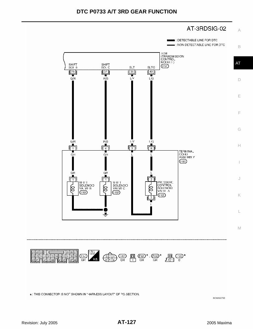
DTC P0733 A/T 3RD GEAR FUNCTION
AT-127
D
E
F
G
H
I
J
K
L
M
A
B
AT
Revision: July 2005 2005 Maxima
BCWA0275E

AT-128
DTC P0733 A/T 3RD GEAR FUNCTION
Revision: July 2005 2005 Maxima
TCM terminals and data are reference value. Measured between each terminal and ground.
Diagnostic Procedure ECS00A3N
1. CHECK EACH SHIFT SOLENOID VALVE CIRCUIT
Perform “Diagnostic Procedure” for the following DTCs. “DTC P0750 SHIFT SOLENOID VALVE A” (Refer to AT-151, "Diagnostic Procedure" .) “DTC P0755 SHIFT SOLENOID VALVE B” (Refer to AT-156, "Diagnostic Procedure" .) “DTC P0760 SHIFT SOLENOID VALVE C” (Refer to AT-161, "Diagnostic Procedure" .) “DTC P0765 SHIFT SOLENOID VALVE D” (Refer to AT-171, "Diagnostic Procedure" .)OK or NGOK >> GO TO 2.NG >> Repair or replace damaged parts.
2. CHECK PRESSURE CONTROL SOLENOID VALVE A CIRCUIT
Perform “Diagnostic Procedure” for DTC P0745. Refer to AT-146, "Diagnostic Procedure" .OK or NGOK >> GO TO 3.NG >> Repair or replace damaged parts.
TerminalWire color
Item Condition Data (Approx.)
25 G/RShift solenoid valve B
When shift solenoid valve B operates.(When driving in 1st or 5th gear.)
Battery voltage
When shift solenoid valve B does not operate. 0V
26 V/WShift solenoid valve D
When shift solenoid valve D operates.(When driving in 3rd, 4th or 5th gear.)
Battery voltage
When shift solenoid valve D does not operate. 0V
35 L/YPressure control solenoid valve A
When engine is running with idle speed and set-ting selector lever to “P” position.
300Hz
37 R/BShift solenoid valve C
When shift solenoid valve C operates.(When driving in 1st, 2nd, 3rd or reverse gear.)
Battery voltage
When shift solenoid valve C does not operate. 0V
40 L/GPressure control solenoid valve A ground
When engine is running with idle speed and set-ting selector lever to “P” position.
0V
46 W/GShift solenoid valve A
When shift solenoid valve A operates.(When driving in 1st gear.)
Battery voltage
When shift solenoid valve A does not operate. 0V

DTC P0733 A/T 3RD GEAR FUNCTION
AT-129
D
E
F
G
H
I
J
K
L
M
A
B
AT
Revision: July 2005 2005 Maxima
3. CHECK MALFUNCTIONING ITEM
1. Control valve assembly. Refer to AT-241, "Control Valve Assembly" .2. Disassembly A/T. Refer to AT-252, "DISASSEMBLY" .3. Check the following item:– B5 brake. Refer to AT-280, "Transaxle Case Cover & B5 Brake" .– U/D clutch. Refer to AT-252, "DISASSEMBLY" .– U/D brake. Refer to AT-252, "DISASSEMBLY" . OK or NG OK >> GO TO 4. NG >> Repair or replace damaged parts.
4. CHECK DTC
Perform “DTC Confirmation Procedure”. Refer to AT-124, "DTC Confirmation Procedure" .OK or NGOK >> INSPECTION ENDNG >> Replace the control valve assembly. Refer to AT-241, "Control Valve Assembly" .

AT-130
DTC P0734 A/T 4TH GEAR FUNCTION
Revision: July 2005 2005 Maxima
DTC P0734 A/T 4TH GEAR FUNCTION PFP:31940
Description ECS00A3O
This malfunction will not be detected while the A/T CHECK indicator lamp is indicating another self-diag-nosis malfunction.
This malfunction is detected when the A/T does not shift into fourth gear position as instructed by theTCM. This is not caused by electrical malfunction (circuits open or shorted) but by mechanical malfunctionsuch as control valve sticking, improper solenoid valve operation, etc.
On Board Diagnosis Logic ECS00A3P
This is an OBD-II self-diagnostic item. Diagnostic trouble code “A/T 4TH GR FNCTN” with CONSULT-II or P0734 without CONSULT-II is
detected when A/T cannot be shifted to the 4th gear position even if electrical circuit is good.
Possible Cause ECS00A3Q
Shift solenoid valve A(On stick.)
Shift solenoid valve B(On stick.)
Shift solenoid valve C(On stick.)
Pressure control solenoid valve A(On stick.)
Forward and direct clutch assembly U/D clutch U/D brake 2nd coast brake One-way clutch No.1 Hydraulic control circuit
DTC Confirmation Procedure ECS00A3R
CAUTION: Always drive vehicle at a safe speed. Be careful not to rev engine into the red zone on the tachometer.NOTE:If “DTC Confirmation Procedure” has been previously performed, always turn ignition switch “OFF”and wait at least 10 seconds before performing the next test.After the repair, perform the following procedure to confirm the malfunction is eliminated.
WITH CONSULT-II1. Start engine and select “A/T” with “DATA MONITOR” mode in
CONSULT-II.2. Make sure that ATF temperature is within the range below.
FLUID TEMP: More than 20°C (68°F)If out of range, drive the vehicle to warm up the fluid.
3. Accelerate vehicle to maintain the following conditions for atleast 10 consecutive seconds.SLCT LVR POSI: “D” positionGEAR: 4th position
Gear positionShift solenoid valve
A B C D E
4thD OFF (Open) OFF (Closed) OFF (Closed) ON (Closed) OFF (Closed)
M4 OFF (Open) OFF (Closed) OFF (Closed) ON (Closed) OFF (Closed)
BCIA0030E

DTC P0734 A/T 4TH GEAR FUNCTION
AT-131
D
E
F
G
H
I
J
K
L
M
A
B
AT
Revision: July 2005 2005 Maxima
[Vehicle speed and accelerator angle: 4th gear position retainable condition. (Refer to AT-312,"VEHICLE SPEED WHEN SHIFTING GEARS" .)]Driving location: Driving the vehicle uphill (increased engine load) will help maintain the drivingconditions required for this test.
4. If DTC is detected, go to AT-133, "Diagnostic Procedure" .
WITH GSTFollow the procedure “With CONSULT-II”.

AT-132
DTC P0734 A/T 4TH GEAR FUNCTION
Revision: July 2005 2005 Maxima
Wiring Diagram — AT — 4THSIG ECS00A3S
BCWA0276E

DTC P0734 A/T 4TH GEAR FUNCTION
AT-133
D
E
F
G
H
I
J
K
L
M
A
B
AT
Revision: July 2005 2005 Maxima
TCM terminals and data are reference value. Measured between each terminal and ground.
Diagnostic Procedure ECS00A3T
1. CHECK EACH SHIFT SOLENOID VALVE CIRCUIT
Perform “Diagnostic Procedure” for the following DTCs. “DTC P0750 SHIFT SOLENOID VALVE A” (Refer to AT-151, "Diagnostic Procedure" .) “DTC P0755 SHIFT SOLENOID VALVE B” (Refer to AT-156, "Diagnostic Procedure" .) “DTC P0760 SHIFT SOLENOID VALVE C” (Refer to AT-161, "Diagnostic Procedure" .)OK or NGOK >> GO TO 2.NG >> Repair or replace damaged parts.
2. CHECK PRESSURE CONTROL SOLENOID VALVE A CIRCUIT
Perform “Diagnostic Procedure” for DTC P0745. Refer to AT-146, "Diagnostic Procedure" .OK or NGOK >> GO TO 3.NG >> Repair or replace damaged parts.
TerminalWire color
Item Condition Data (Approx.)
25 G/RShift solenoid valve B
When shift solenoid valve B operates.(When driving in 1st or 5th gear.)
Battery voltage
When shift solenoid valve B does not operate. 0V
35 L/YPressure control solenoid valve A
When engine is running with idle speed and set-ting selector lever to “P” position.
300Hz
37 R/BShift solenoid valve C
When shift solenoid valve C operates.(When driving in 1st, 2nd, 3rd or reverse gear.)
Battery voltage
When shift solenoid valve C does not operate. 0V
40 L/GPressure control solenoid valve A ground
When engine is running with idle speed and set-ting selector lever to “P” position.
0V
46 W/GShift solenoid valve A
When shift solenoid valve A operates.(When driving in 1st gear.)
Battery voltage
When shift solenoid valve A does not operate. 0V

AT-134
DTC P0734 A/T 4TH GEAR FUNCTION
Revision: July 2005 2005 Maxima
3. CHECK MALFUNCTIONING ITEM
1. Control valve assembly. Refer to AT-241, "Control Valve Assembly" .2. Disassembly A/T. Refer to AT-252, "DISASSEMBLY" .3. Check the following item:– Forward and direct clutch assembly. Refer to AT-252, "DISASSEMBLY" .– 2nd coast brake. Refer to AT-272, "Oil Pump, 2nd Coast Brake & 2nd Brake" , AT-278, "One-Way Clutch
Outer Race Sub Assembly & 2nd Coast Brake Hub & One-Way Clutch No.1" .– U/D brake. Refer to AT-252, "DISASSEMBLY" .– U/D clutch. Refer to AT-252, "DISASSEMBLY" .– One-way clutch No.1. Refer to AT-278, "One-Way Clutch Outer Race Sub Assembly & 2nd Coast Brake
Hub & One-Way Clutch No.1" . OK or NG OK >> GO TO 4. NG >> Repair or replace damaged parts.
4. CHECK DTC
Perform “DTC Confirmation Procedure”. Refer to AT-130, "DTC Confirmation Procedure" .OK or NGOK >> INSPECTION ENDNG >> Replace the control valve assembly. Refer to AT-241, "Control Valve Assembly" .

DTC P0735 A/T 5TH GEAR FUNCTION
AT-135
D
E
F
G
H
I
J
K
L
M
A
B
AT
Revision: July 2005 2005 Maxima
DTC P0735 A/T 5TH GEAR FUNCTION PFP:31940
Description ECS00A3U
This malfunction will not be detected while the A/T CHECK indicator lamp is indicating another self-diag-nosis malfunction.
This malfunction is detected when the A/T does not shift into fifth gear position as instructed by the TCM.This is not caused by electrical malfunction (circuits open or shorted) but by mechanical malfunction suchas control valve sticking, improper solenoid valve operation, etc.
On Board Diagnosis Logic ECS00A3V
This is an OBD-II self-diagnostic item. Diagnostic trouble code “A/T 5TH GR FNCTN” with CONSULT-II or P0735 without CONSULT-II is
detected when A/T cannot be shifted to the 5th gear position even if electrical circuit is good.
Possible Cause ECS00A3W
Shift solenoid valve B(Off stick.)
Shift solenoid valve C(On stick.)
Shift solenoid valve E(On stick.)
Pressure control solenoid valve A(On stick.)
Pressure control solenoid valve B(On stick.)
Forward and direct clutch assembly Direct clutch 2no coast brake One-way clutch No.1 Hydraulic control circuit
DTC Confirmation Procedure ECS00A3X
CAUTION: Always drive vehicle at a safe speed. Be careful not to rev engine into the red zone on the tachometer.NOTE:If “DTC Confirmation Procedure” has been previously performed, always turn ignition switch “OFF”and wait at least 10 seconds before performing the next test.After the repair, perform the following procedure to confirm the malfunction is eliminated.
Gear positionShift solenoid valve
A B C D E
5thD OFF (Open) ON (Open) OFF (Closed) ON (Closed) OFF (Closed)
M5 OFF (Open) ON (Open) OFF (Closed) ON (Closed) OFF (Closed)

AT-136
DTC P0735 A/T 5TH GEAR FUNCTION
Revision: July 2005 2005 Maxima
WITH CONSULT-II1. Start engine and select “DATA MONITOR” mode for “A/T” with
CONSULT-II.2. Make sure that ATF temperature is within the range below.
FLUID TEMP: More than 20°C (68°F)If out of range, drive the vehicle to warm up the fluid.
3. Accelerate vehicle to maintain the following conditions for atleast 12 consecutive seconds.SLCT LVR POSI: “D” positionGEAR: 5th position[Vehicle speed and accelerator angle: 5th gear positionretainable condition. (Refer to AT-312, "VEHICLE SPEEDWHEN SHIFTING GEARS" .)]Driving location: Driving the vehicle uphill (increased engine load) will help maintain the drivingconditions required for this test.
4. If DTC is detected, go to AT-139, "Diagnostic Procedure" .
WITH GSTFollow the procedure “With CONSULT-II”.
BCIA0030E

DTC P0735 A/T 5TH GEAR FUNCTION
AT-137
D
E
F
G
H
I
J
K
L
M
A
B
AT
Revision: July 2005 2005 Maxima
Wiring Diagram — AT — 5THSIG ECS00A3Y
BCWA0277E

AT-138
DTC P0735 A/T 5TH GEAR FUNCTION
Revision: July 2005 2005 Maxima
BCWA0278E

DTC P0735 A/T 5TH GEAR FUNCTION
AT-139
D
E
F
G
H
I
J
K
L
M
A
B
AT
Revision: July 2005 2005 Maxima
TCM terminals and data are reference value. Measured between each terminal and ground.
Diagnostic Procedure ECS00A3Z
1. CHECK EACH SHIFT SOLENOID VALVE CIRCUIT
Perform “Diagnostic Procedure” for the following DTCs. “DTC P0755 SHIFT SOLENOID VALVE B” (Refer to AT-156, "Diagnostic Procedure" .) “DTC P0760 SHIFT SOLENOID VALVE C” (Refer to AT-161, "Diagnostic Procedure" .) “DTC P0770 SHIFT SOLENOID VALVE E” (Refer to AT-176, "Diagnostic Procedure" .)OK or NGOK >> GO TO 2.NG >> Repair or replace damaged parts.
2. CHECK EACH PRESSURE CONTROL SOLENOID VALVE CIRCUIT
Perform “Diagnostic Procedure” for the following DTCs. “DTC P0745 PRESSURE CONTROL SOLENOID VALVE A” (Refer to AT-146, "Diagnostic Procedure" .) “DTC P0775 PRESSURE CONTROL SOLENOID VALVE B” (Refer to AT-181, "Diagnostic Procedure" .)OK or NGOK >> GO TO 3.NG >> Repair or replace damaged parts.
TerminalWire color
Item Condition Data (Approx.)
21 G/BPressure control solenoid valve B ground
When engine is running with idle speed and set-ting selector lever to “P” position.
0V
25 G/RShift solenoid valve B
When shift solenoid valve B operates.(When driving in 1st or 5th gear.)
Battery voltage
When shift solenoid valve B does not operate. 0V
35 L/YPressure control solenoid valve A
When engine is running with idle speed and set-ting selector lever to “P” position.
300Hz
36 O/BPressure control solenoid valve B
When engine is running with idle speed and set-ting selector lever to “P” position.
300Hz
37 R/B Shift solenoid valve C
When shift solenoid valve C operates.(When driving in 1st, 2nd, 3rd or reverse gear.)
Battery voltage
When shift solenoid valve C does not operate. 0V
40 L/GPressure control solenoid valve A ground
When engine is running with idle speed and set-ting selector lever to “P” position.
0V
47 BR/YShift solenoid valve E
When shift solenoid valve E operates.(When driving in reverse gear.)
Battery voltage
When shift solenoid valve E does not operate. 0V

AT-140
DTC P0735 A/T 5TH GEAR FUNCTION
Revision: July 2005 2005 Maxima
3. CHECK MALFUNCTIONING ITEM
1. Control valve assembly. Refer to AT-241, "Control Valve Assembly" .2. Disassembly A/T. Refer to AT-252, "DISASSEMBLY" .3. Check the following item:– Forward and direct clutch assembly. Refer to AT-252, "DISASSEMBLY" .– 2nd brake. Refer to AT-272, "Oil Pump, 2nd Coast Brake & 2nd Brake" .– One-way clutch No.1. Refer to AT-278, "One-Way Clutch Outer Race Sub Assembly & 2nd Coast Brake
Hub & One-Way Clutch No.1" . OK or NG OK >> GO TO 4. NG >> Repair or replace damaged parts.
4. CHECK DTC
Perform “DTC Confirmation Procedure”. Refer to AT-135, "DTC Confirmation Procedure" .OK or NGOK >> INSPECTION ENDNG >> Replace the control valve assembly. Refer to AT-241, "Control Valve Assembly" .

DTC P0744 A/T TCC S/V FUNCTION (LOCK-UP)
AT-141
D
E
F
G
H
I
J
K
L
M
A
B
AT
Revision: July 2005 2005 Maxima
DTC P0744 A/T TCC S/V FUNCTION (LOCK-UP) PFP:31940
Description ECS00A40
This malfunction will not be detected while the A/T CHECK indicator lamp is indicating another self-diag-nosis malfunction.
This malfunction is detected when the torque converter clutch does not lock up as instructed by the TCM.This is not caused by electrical malfunction (circuits open or shorted) but by mechanical malfunction suchas control valve sticking, improper solenoid valve operation, malfunctioning oil pump or torque converterclutch, etc.
On Board Diagnosis Logic ECS00A41
This is an OBD-II self-diagnostic item. Diagnostic trouble code “A/T TCC S/V FNCTN” with CONSULT-II or P0744 without CONSULT-II is
detected when A/T cannot perform lock-up even if electrical circuit is good.
Possible Cause ECS00A42
Shift solenoid valve D(Off stick.)
Pressure control solenoid valve C(Off stick.)
Torque converter clutch Hydraulic control circuit
DTC Confirmation Procedure ECS00A43
CAUTION: Always drive vehicle at a safe speed. Be careful not to rev engine into the red zone on the tachometer.NOTE:If “DTC Confirmation Procedure” has been previously performed, always turn ignition switch “OFF”and wait at least 10 seconds before performing the next test.After the repair, perform the following procedure to confirm the malfunction is eliminated.
WITH CONSULT-II1. Start engine and select “DATA MONITOR” mode for “A/T” with
CONSULT-II.2. Make sure that ATF temperature is within the range below.
FLUID TEMP: More than 20°C (68°F)If out of range, drive the vehicle to warm up the fluid.
3. Accelerate vehicle to more than 100 km/h (62 MPH) and main-tain the following conditions for at least 12 consecutive seconds.SLCT LVR POSI: “D” positionGEAR: 5th positionSLIP REV: Less than 100 rpmACCELE ANGLE: More than 5 % LOCK-UP: ON (Refer to AT-313, "VEHICLE SPEED WHENPERFORMING AND RELEASING COMPLETE LOCK-UP" .)[Vehicle speed: Constant speed of more than 100 km/h (62 MPH).]Driving location: Driving the vehicle uphill (increased engine load) will help maintain the drivingconditions required for this test.
4. If DTC is detected, go to AT-143, "Diagnostic Procedure" .
WITH GSTFollow the procedure “With CONSULT-II”.
BCIA0030E

AT-142
DTC P0744 A/T TCC S/V FUNCTION (LOCK-UP)
Revision: July 2005 2005 Maxima
Wiring Diagram — AT — TCCSIG ECS00A44
BCWA0279E

DTC P0744 A/T TCC S/V FUNCTION (LOCK-UP)
AT-143
D
E
F
G
H
I
J
K
L
M
A
B
AT
Revision: July 2005 2005 Maxima
TCM terminals and data are reference value. Measured between each terminal and ground.
Diagnostic Procedure ECS00A45
1. CHECK SHIFT SOLENOID VALVE D CIRCUIT
Perform “Diagnostic Procedure” for DTC P0765. Refer to AT-171, "Diagnostic Procedure" .OK or NGOK >> GO TO 2.NG >> Repair or replace damaged parts.
2. CHECK PRESSURE CONTROL SOLENOID VALVE C CIRCUIT
Perform “Diagnostic Procedure” for DTC P0795. Refer to AT-190, "Diagnostic Procedure" .OK or NGOK >> GO TO 3.NG >> Repair or replace damaged parts.
3. CHECK MALFUNCTIONING ITEM
1. Control valve assembly. Refer to AT-241, "Control Valve Assembly" .2. Disassembly A/T. Refer to AT-252, "DISASSEMBLY" .3. Check the following item:– Torque converter clutch. Refer to AT-252, "DISASSEMBLY" . OK or NG OK >> GO TO 4. NG >> Repair or replace damaged parts.
4. CHECK DTC
Perform “DTC Confirmation Procedure”. Refer to AT-141, "DTC Confirmation Procedure" .OK or NGOK >> INSPECTION ENDNG >> Replace the control valve assembly. Refer to AT-241, "Control Valve Assembly" .
TerminalWire color
Item Condition Data (Approx.)
28 WPressure control solenoid valve C ground
When engine is running with idle speed and set-ting selector lever to “P” position.
0V
45 OPressure control solenoid valve C
When engine is running with idle speed and set-ting selector lever to “P” position.
300Hz

AT-144
DTC P0745 PRESSURE CONTROL SOLENOID VALVE A (LINE PRESSURE)
Revision: July 2005 2005 Maxima
DTC P0745 PRESSURE CONTROL SOLENOID VALVE A (LINE PRESSURE)PFP:31940
Description ECS00A46
The pressure control solenoid valve A is normally high, 3-portlinear pressure control solenoid.
The pressure control solenoid valve A regulates the oil pumpdischarge pressure to suit the driving condition in response to asignal sent from the TCM.
On Board Diagnosis Logic ECS00A47
This is an OBD-II self-diagnostic item. Diagnostic trouble code “PC SOL A(L/PRESS)” with CONSULT-II or P0745 without CONSULT-II is
detected under the following conditions.– When normal voltage is not applied to solenoid due to open, short, and so on.– When TCM detects as irregular by comparing target value with monitor value.
Possible Cause ECS00A48
Harness or connectors(The solenoid circuit is open or shorted.)
Pressure control solenoid valve A
DTC Confirmation Procedure ECS00A49
NOTE:If “DTC Confirmation Procedure” has been previously performed, always turn ignition switch “OFF”and wait at least 10 seconds before performing the next test.After the repair, perform the following procedure to confirm the malfunction is eliminated.
WITH CONSULT-II1. Turn ignition switch “ON”. (Do not start engine.)2. Select “A/T” with “DATA MONITOR” mode in CONSULT-II.3. Start engine.4. Run engine for at least 13 consecutive seconds at idle speed.5. If DTC is detected, go to AT-146, "Diagnostic Procedure" .
WITH GSTFollow the procedure “With CONSULT-II”.
SCIA2831E
BCIA0030E
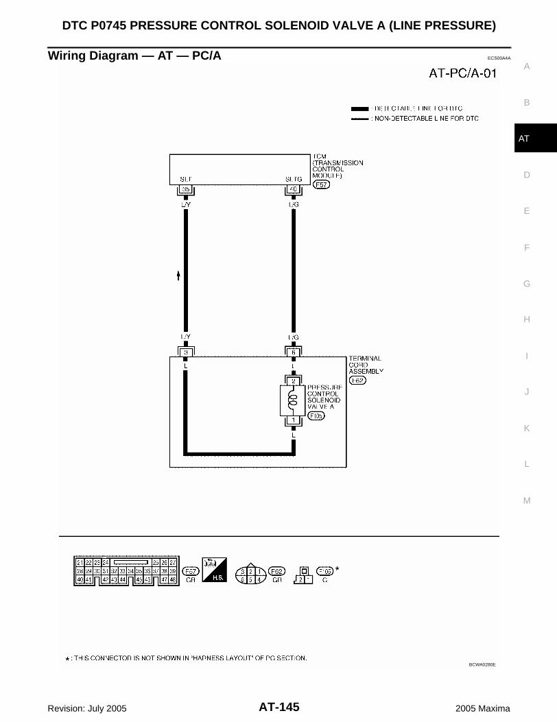
DTC P0745 PRESSURE CONTROL SOLENOID VALVE A (LINE PRESSURE)
AT-145
D
E
F
G
H
I
J
K
L
M
A
B
AT
Revision: July 2005 2005 Maxima
Wiring Diagram — AT — PC/A ECS00A4A
BCWA0280E

AT-146
DTC P0745 PRESSURE CONTROL SOLENOID VALVE A (LINE PRESSURE)
Revision: July 2005 2005 Maxima
TCM terminals and data are reference value. Measured between each terminal and ground.
Diagnostic Procedure ECS00A4B
1. CHECK PRESSURE CONTROL SOLENOID VALVE A SIGNAL
With CONSULT-II1. After warming up the engine and transaxle, turn ignition switch “OFF”.2. Turn ignition switch “ON”. (Do not start engine.)3. Select “DATA MONITOR” mode for “A/T” with CONSULT-II.4. Read out the value of “PC SOL A OUT” and “PC SOL A MON”.
Without CONSULT-II1. Start the engine.2. Check pulse between TCM connector terminals 35 and 40.
OK or NGOK >> GO TO 7.NG >> GO TO 2.
2. CHECK PRESSURE CONTROL SOLENOID VALVE A CIRCUIT
1. Turn ignition switch “OFF”.2. Disconnect the TCM connector.3. Check resistance between TCM connector terminals 35 and 40.
OK or NG OK >> GO TO 7. NG >> GO TO 3.
TerminalWire color
Item Condition Data (Approx.)
35 L/YPressure control solenoid valve A
When engine is running with idle speed and set-ting selector lever to “P” position.
300Hz
40 L/GPressure control solenoid valve A ground
When engine is running with idle speed and set-ting selector lever to “P” position.
0V
Monitor item ConditionDisplay value
(Approx.)
PC SOL A OUT
PC SOL A MON
When releasing accelerator pedal with set-ting selector lever to “P” position.
1.00 A
When depressing accelerator pedal fully set-ting selector lever to “P” position.
0.32 A
SCIA2907E
ConnectorTerminal (Wire
color)Condition
Data (Approx.)
F57 35 (L/Y) - 40 (L/G)When engine is running with idle speed and setting selector lever to “P” position.
300 Hz
SCIA2908E
ConnectorTerminal (Wire
color)Condition
Resistance (Approx.)
F57 35 (L/Y) - 40 (L/G) Temperature: 20°C (68°F) 5.0 - 5.6 Ω
SCIA2909E

DTC P0745 PRESSURE CONTROL SOLENOID VALVE A (LINE PRESSURE)
AT-147
D
E
F
G
H
I
J
K
L
M
A
B
AT
Revision: July 2005 2005 Maxima
3. CHECK TERMINAL CORD ASSEMBLY WITH PRESSURE CONTROL SOLENOID VALVE A
1. Turn ignition switch “OFF”.2. Disconnect terminal cord assembly harness connector.3. Check resistance between terminals 3 and 6.
OK or NGOK >> GO TO 4.NG >> GO TO 5.
4. CHECK HARNESS BETWEEN TCM AND TERMINAL CORD ASSEMBLY
Check the following. Open or short-circuit in the harness between TCM and terminal cord assembly.OK or NGOK >> GO TO 7.NG >> Repair or replace damaged parts.
5. CHECK PRESSURE CONTROL SOLENOID VALVE A
1. Remove side cover. Refer to AT-241, "Side cover" .2. Disconnect pressure control solenoid valve A harness connector.3. Check resistance between terminals 1 and 2.
OK or NGOK >> GO TO 6.NG >> Replace the control valve assembly. Refer to AT-241,
"Control Valve Assembly" .
6. CHECK HARNESS BETWEEN TERMINAL CORD ASSEMBLY AND PRESSURE CONTROL SOLE-NOID VALVE A
Check the following. Open or short-circuit in the harness between terminal cord assembly and pressure control solenoid valve
A.OK or NGOK >> GO TO 7.NG >> Repair or replace transmission wire. Refer to AT-241, "Terminal cord assembly" .
7. CHECK DTC
Perform “DTC Confirmation Procedure”. Refer to AT-144, "DTC Confirmation Procedure" .OK or NG OK >> INSPECTION ENDNG >> GO TO 8.
Connector Terminal Condition Resistance (Approx.)
F62 3 - 6 Temperature: 20°C (68°F) 5.0 - 5.6 Ω
SCIA2910E
Connector Terminal Condition Resistance (Approx.)
F105 1 - 2 Temperature: 20°C (68°F) 5.0 - 5.6 Ω
SCIA4326E

AT-148
DTC P0745 PRESSURE CONTROL SOLENOID VALVE A (LINE PRESSURE)
Revision: July 2005 2005 Maxima
8. CHECK TCM
1. Check TCM input/output signal. Refer to AT-71, "TCM Input/Output Signal Reference Values" .2. If NG, recheck TCM pin terminals for damage or loose connection with harness connector.OK or NGOK >> INSPECTION ENDNG >> Repair or replace damaged parts.
Component Inspection ECS00A4C
PRESSURE CONTROL SOLENOID VALVE A1. Remove side cover. Refer to AT-241, "Side cover" .2. Disconnect pressure control solenoid valve A harness connector.3. Check resistance between terminals 1 and 2.
4. If NG, replace the control valve assembly. Refer to AT-241,"Control Valve Assembly" .
Connector Terminal Condition Resistance (Approx.)
F105 1 - 2 Temperature: 20°C (68°F) 5.0 - 5.6 Ω
SCIA4326E

DTC P0750 SHIFT SOLENOID VALVE A
AT-149
D
E
F
G
H
I
J
K
L
M
A
B
AT
Revision: July 2005 2005 Maxima
DTC P0750 SHIFT SOLENOID VALVE A PFP:31940
Description ECS00A4D
Shift solenoid valves are installed directly in control valve body. The shift solenoid valves operates of ONand OFF by the control signal from TCM. Combinations of 5 shift solenoid valves, A, B, C, D and E, shiftsgear positions.
The shift solenoid valve A is a normally open, ON-OFF type solenoid.
On Board Diagnosis Logic ECS00A4E
This is an OBD-II self-diagnostic item. Diagnostic trouble code “SHIFT SOL A” with CONSULT-II or P0750 without CONSULT-II is detected
under the following conditions.– When normal voltage is not applied to solenoid due to open, short, and so on.– When TCM detects as irregular by comparing target value with monitor value.
Possible Cause ECS00A4F
Harness or connectors(The solenoid circuit is open or shorted.)
Shift solenoid valve A
DTC Confirmation Procedure ECS00A4G
CAUTION: Always drive vehicle at a safe speed. Be careful not to rev engine into the red zone on the tachometer.NOTE:If “DTC Confirmation Procedure” has been previously performed, always turn ignition switch “OFF”and wait at least 10 seconds before performing the next test.After the repair, perform the following procedure to confirm the malfunction is eliminated.
WITH CONSULT-II1. Turn ignition switch “ON”. (Do not start engine.)2. Select “A/T” with “DATA MONITOR” mode in CONSULT-II.3. Start engine.4. Drive vehicle and allow the following conditions.
SLCT LVR POSI: “D” positionGEAR: 1st 2nd position
5. If DTC is detected, go to AT-151, "Diagnostic Procedure" .
WITH GSTFollow the procedure “With CONSULT-II”.
Gear position D1 , M1 D2 , M2 D3 , M3 D4 , M4 D5 , M5 Reverse
Shift solenoid valve A ON (Closed) OFF (Open) OFF (Open) OFF (Open) OFF (Open) OFF (Open)
BCIA0030E

AT-150
DTC P0750 SHIFT SOLENOID VALVE A
Revision: July 2005 2005 Maxima
Wiring Diagram — AT — SSV/A ECS00A4H
BCWA0281E

DTC P0750 SHIFT SOLENOID VALVE A
AT-151
D
E
F
G
H
I
J
K
L
M
A
B
AT
Revision: July 2005 2005 Maxima
TCM terminal and data are reference value. Measured between each terminal and ground.
Diagnostic Procedure ECS00A4I
1. CHECK SHIFT SOLENOID VALVE A SIGNAL
With CONSULT-II1. Start engine.2. Select “A/T” with “DATA MONITOR” mode in CONSULT-II.3. Drive vehicle and read out the value of “SFT SOL A OUT” and
“SFT SOL A MON”.
Without CONSULT-II 1. Drive vehicle.2. Check voltage between TCM connector terminal and ground.
OK or NGOK >> GO TO 7.NG >> GO TO 2.
2. CHECK SHIFT SOLENOID VALVE A CIRCUIT
1. Turn ignition switch “OFF”.2. Disconnect the TCM connector.3. Check resistance between TCM connector terminal 46 and
ground.
OK or NG OK >> GO TO 7. NG >> GO TO 3.
TerminalWire color
Item Condition Data (Approx.)
46 W/GShift solenoid valve A
When shift solenoid valve A operates.(When driving in 1st gear.)
Battery voltage
When shift solenoid valve A does not operate. 0V
Monitor item Condition Indication
SFT SOL A OUT
SFT SOL A MON
When shift solenoid valve A operates.(When driving in 1st gear.)
ON
When shift solenoid valve A does not operate. OFF
SCIA2874E
Connector Terminal (Wire color) ConditionVoltage
(Approx.)
F57 46 (W/G) - Ground
When shift solenoid valve A operates. (When driving in 1st gear.)
Battery voltage
When shift solenoid valve A does not operate.
0V
SCIA2875E
Connector Terminal (Wire color) Condition Resistance (Approx.)
F57 46 (W/G) - Ground Temperature: 20°C (68°F) 11 - 16 Ω
SCIA2877E

AT-152
DTC P0750 SHIFT SOLENOID VALVE A
Revision: July 2005 2005 Maxima
3. CHECK TERMINAL CORD ASSEMBLY WITH SHIFT SOLENOID VALVE A
1. Turn ignition switch “OFF”.2. Disconnect terminal cord assembly harness connector.3. Check resistance between terminal 2 and ground.
OK or NGOK >> GO TO 4.NG >> GO TO 5.
4. CHECK HARNESS BETWEEN TCM AND TERMINAL CORD ASSEMBLY
Check the following. Open or short-circuit in the harness between TCM and terminal cord assembly.OK or NGOK >> GO TO 7.NG >> Repair or replace damaged parts.
5. CHECK SHIFT SOLENOID VALVE A
1. Remove side cover. Refer to AT-241, "Side cover" .2. Disconnect shift solenoid valve A harness connector.3. Check resistance between terminal 1 and ground.
OK or NGOK >> GO TO 6.NG >> Replace the control valve assembly. Refer to AT-241,
"Control Valve Assembly" .
6. CHECK HARNESS BETWEEN TERMINAL CORD ASSEMBLY AND SHIFT SOLENOID VALVE A
Check the following. Open or short-circuit in the harness between terminal cord assembly and shift solenoid valve A.OK or NGOK >> GO TO 7.NG >> Repair or replace transmission wire. Refer to AT-241, "Terminal cord assembly" .
7. CHECK DTC
Perform “DTC Confirmation Procedure”. Refer to AT-149, "DTC Confirmation Procedure" .OK or NGOK >> INSPECTION ENDNG >> GO TO 8.
Connector Terminal Condition Resistance (Approx.)
F30 2 - Ground Temperature: 20°C (68°F) 11 - 16 Ω
WCIA0449E
Connector Terminal Condition Resistance (Approx.)
F100 1 - Ground Temperature: 20°C (68°F) 11 - 16 Ω
SCIA4334E

DTC P0750 SHIFT SOLENOID VALVE A
AT-153
D
E
F
G
H
I
J
K
L
M
A
B
AT
Revision: July 2005 2005 Maxima
8. CHECK TCM
1. Check TCM input/output signal. Refer to AT-71, "TCM Input/Output Signal Reference Values" .2. If NG, recheck TCM pin terminals for damage or loose connection with harness connector.OK or NGOK >> INSPECTION ENDNG >> Repair or replace damaged parts.
Component Inspection ECS00A4J
SHIFT SOLENOID VALVE A1. Remove side cover. Refer to AT-241, "Side cover" .2. Disconnect shift solenoid valve A harness connector.3. Check resistance between terminal 1 and ground.
4. If NG, replace the control valve assembly. Refer to AT-241,"Control Valve Assembly" .
Connector Terminal Condition Resistance (Approx.)
F100 1 - Ground Temperature: 20°C (68°F) 11 - 16 Ω
SCIA4334E

AT-154
DTC P0755 SHIFT SOLENOID VALVE B
Revision: July 2005 2005 Maxima
DTC P0755 SHIFT SOLENOID VALVE B PFP:31940
Description ECS00A4K
Shift solenoid valves are installed directly in control valve body. The shift solenoid valves operates of ONand OFF by the control signal from TCM. Combinations of 5 shift solenoid valves, A, B, C, D and E, shiftsgear positions.
The shift solenoid valve B is a normally closed, ON-OFF type solenoid.
On Board Diagnosis Logic ECS00A4L
This is an OBD-II self-diagnostic item. Diagnostic trouble code “SHIFT SOL B” with CONSULT-II or P0755 without CONSULT-II is detected
under the following conditions.– When normal voltage is not applied to solenoid due to open, short, and so on.– When TCM detects as irregular by comparing target value with monitor value.
Possible Cause ECS00A4M
Harness or connectors(The solenoid circuit is open or shorted.)
Shift solenoid valve B
DTC Confirmation Procedure ECS00A4N
CAUTION: Always drive vehicle at a safe speed. Be careful not to rev engine into the red zone on the tachometer.NOTE:If “DTC Confirmation Procedure” has been previously performed, always turn ignition switch “OFF”and wait at least 10 seconds before performing the next test.After the repair, perform the following procedure to confirm the malfunction is eliminated.
WITH CONSULT-II1. Turn ignition switch “ON”. (Do not start engine.)2. Select “A/T” with “DATA MONITOR” mode in CONSULT-II.3. Start engine.4. Drive vehicle and allow the following conditions.
SLCT LVR POSI: “D” positionGEAR: 1st 2nd and 4th 5th position
5. If DTC is detected, go to AT-156, "Diagnostic Procedure" .
WITH GSTFollow the procedure “With CONSULT-II”.
Gear position D1 , M1 D2 , M2 D3 , M3 D4 , M4 D5 , M5 Reverse
Shift solenoid valve B ON (Open) OFF (Closed) OFF (Closed) OFF (Closed) ON (Open) OFF (Closed)
BCIA0030E
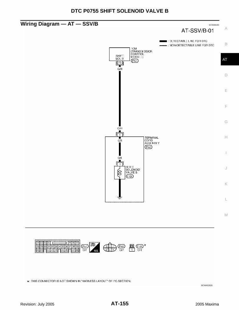
DTC P0755 SHIFT SOLENOID VALVE B
AT-155
D
E
F
G
H
I
J
K
L
M
A
B
AT
Revision: July 2005 2005 Maxima
Wiring Diagram — AT — SSV/B ECS00A4O
BCWA0282E

AT-156
DTC P0755 SHIFT SOLENOID VALVE B
Revision: July 2005 2005 Maxima
TCM terminal and data are reference value. Measured between each terminal and ground.
Diagnostic Procedure ECS00A4P
1. CHECK SHIFT SOLENOID VALVE B SIGNAL
With CONSULT-II1. Start engine.2. Select “A/T” with “DATA MONITOR” mode in CONSULT-II.3. Drive vehicle and read out the value of “SFT SOL B OUT” and
“SFT SOL B MON”.
Without CONSULT-II1. Drive vehicle.2. Check voltage between TCM connector terminal and ground.
OK or NGOK >> GO TO 7.NG >> GO TO 2.
2. CHECK SHIFT SOLENOID VALVE B CIRCUIT
1. Turn ignition switch “OFF”.2. Disconnect the TCM connector.3. Check resistance between TCM connector terminal 25 and
ground.
OK or NG OK >> GO TO 7. NG >> GO TO 3.
TerminalWire color
Item Condition Data (Approx.)
25 G/RShift solenoid valve B
When shift solenoid valve B operates.(When driving in 1st or 5th gear.)
Battery voltage
When shift solenoid valve B does not operate. 0V
Monitor item Condition Indication
SFT SOL B OUT
SFT SOL B MON
When shift solenoid valve B operates.(When driving in 1st or 5th gear.)
ON
When shift solenoid valve B does not operate. OFF
SCIA2879E
Connector Terminal (Wire color) ConditionVoltage
(Approx.)
F57 25 (G/R) - Ground
When shift solenoid valve B operates.(When driving in 1st or 5th gear.)
Battery voltage
When shift solenoid valve B does not operate.
0V
SCIA2880E
Connector Terminal (Wire color) Condition Resistance
(Approx.)
F57 25 (G/R) - Ground Temperature: 20°C (68°F) 11 - 16 Ω
SCIA2881E

DTC P0755 SHIFT SOLENOID VALVE B
AT-157
D
E
F
G
H
I
J
K
L
M
A
B
AT
Revision: July 2005 2005 Maxima
3. CHECK TERMINAL CORD ASSEMBLY WITH SHIFT SOLENOID VALVE B
1. Turn ignition switch “OFF”.2. Disconnect terminal cord assembly harness connector.3. Check resistance between terminal 1 and ground.
OK or NGOK >> GO TO 4.NG >> GO TO 5.
4. CHECK HARNESS BETWEEN TCM AND TERMINAL CORD ASSEMBLY
Check the following. Open or short-circuit in the harness between TCM and terminal cord assembly.OK or NGOK >> GO TO 7.NG >> Repair or replace damaged parts.
5. CHECK SHIFT SOLENOID VALVE B
1. Remove side cover. Refer to AT-241, "Side cover" .2. Disconnect shift solenoid valve B harness connector.3. Check resistance between terminal 1 and ground.
OK or NGOK >> GO TO 6.NG >> Replace the control valve assembly. Refer to AT-241,
"Control Valve Assembly" .
6. CHECK HARNESS BETWEEN TERMINAL CORD ASSEMBLY AND SHIFT SOLENOID VALVE B
Check the following. Open or short-circuit in the harness between terminal cord assembly and shift solenoid valve B.OK or NGOK >> GO TO 7.NG >> Repair or replace transmission wire. Refer to AT-241, "Terminal cord assembly" .
7. CHECK DTC
Perform “DTC Confirmation Procedure”. Refer to AT-154, "DTC Confirmation Procedure" .OK or NGOK >> INSPECTION ENDNG >> GO TO 8.
Connector Terminal Condition Resistance (Approx.)
F62 1 - Ground Temperature: 20°C (68°F) 11 - 16 Ω
WCIA0450E
Connector Terminal Condition Resistance (Approx.)
F101 1 - Ground Temperature: 20°C (68°F) 11 - 16 Ω
SCIA4335E
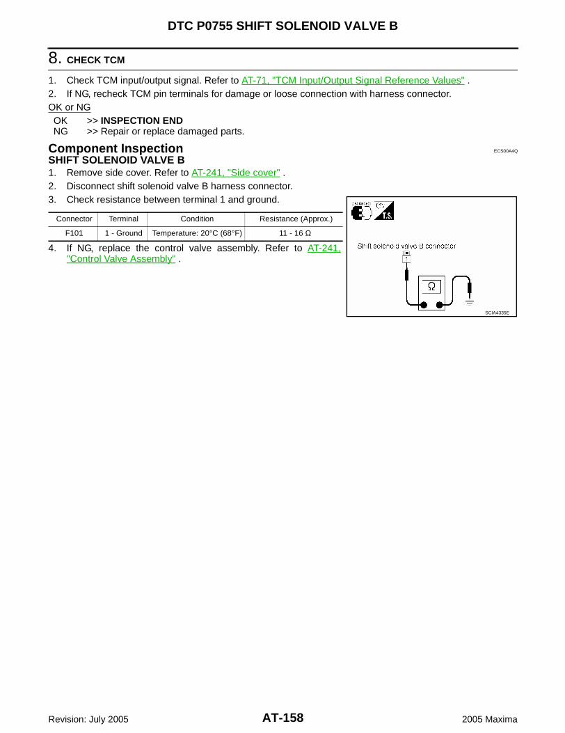
AT-158
DTC P0755 SHIFT SOLENOID VALVE B
Revision: July 2005 2005 Maxima
8. CHECK TCM
1. Check TCM input/output signal. Refer to AT-71, "TCM Input/Output Signal Reference Values" .2. If NG, recheck TCM pin terminals for damage or loose connection with harness connector.OK or NGOK >> INSPECTION ENDNG >> Repair or replace damaged parts.
Component Inspection ECS00A4Q
SHIFT SOLENOID VALVE B1. Remove side cover. Refer to AT-241, "Side cover" .2. Disconnect shift solenoid valve B harness connector.3. Check resistance between terminal 1 and ground.
4. If NG, replace the control valve assembly. Refer to AT-241,"Control Valve Assembly" .
Connector Terminal Condition Resistance (Approx.)
F101 1 - Ground Temperature: 20°C (68°F) 11 - 16 Ω
SCIA4335E

DTC P0760 SHIFT SOLENOID VALVE C
AT-159
D
E
F
G
H
I
J
K
L
M
A
B
AT
Revision: July 2005 2005 Maxima
DTC P0760 SHIFT SOLENOID VALVE C PFP:31940
Description ECS00A4R
Shift solenoid valves are installed directly in control valve body. The shift solenoid valves operates of ONand OFF by the control signal from TCM. Combinations of 5 shift solenoid valves, A, B, C, D and E, shiftsgear positions.
The shift solenoid valve C is a normally closed, ON-OFF type solenoid.
On Board Diagnosis Logic ECS00A4S
This is an OBD-II self-diagnostic item. Diagnostic trouble code “SHIFT SOL C” with CONSULT-II or P0760 without CONSULT-II is detected
under the following conditions.– When normal voltage is not applied to solenoid due to open, short, and so on.– When TCM detects as irregular by comparing target value with monitor value.
Possible Cause ECS00A4T
Harness or connectors(The solenoid circuit is open or shorted.)
Shift solenoid valve C
DTC Confirmation Procedure ECS00A4U
CAUTION: Always drive vehicle at a safe speed. Be careful not to rev engine into the red zone on the tachometer.NOTE:If “DTC Confirmation Procedure” has been previously performed, always turn ignition switch “OFF”and wait at least 10 seconds before performing the next test.After the repair, perform the following procedure to confirm the malfunction is eliminated.
WITH CONSULT-II1. Turn ignition switch “ON”. (Do not start engine.)2. Select “A/T” with “DATA MONITOR” mode in CONSULT-II.3. Start engine.4. Drive vehicle and allow the following conditions.
SLCT LVR POSI: “D” positionGEAR: 3rd 4th position
5. If DTC is detected, go to AT-161, "Diagnostic Procedure" .
WITH GSTFollow the procedure “With CONSULT-II”.
Gear position D1 , M1 D2 , M2 D3 , M3 D4 , M4 D5 , M5 Reverse
Shift solenoid valve C ON (Open) ON (Open) ON (Open) OFF (Closed) OFF (Closed) ON (Open)
BCIA0030E
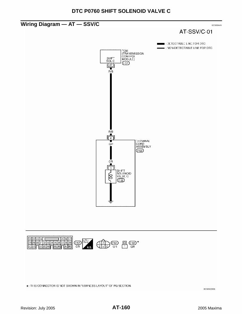
AT-160
DTC P0760 SHIFT SOLENOID VALVE C
Revision: July 2005 2005 Maxima
Wiring Diagram — AT — SSV/C ECS00A4V
BCWA0283E

DTC P0760 SHIFT SOLENOID VALVE C
AT-161
D
E
F
G
H
I
J
K
L
M
A
B
AT
Revision: July 2005 2005 Maxima
TCM terminal and data are reference value. Measured between each terminal and ground.
Diagnostic Procedure ECS00A4W
1. CHECK SHIFT SOLENOID VALVE C SIGNAL
With CONSULT-II1. Start engine.2. Select “A/T” with “DATA MONITOR” mode in CONSULT-II.3. Drive vehicle and read out the value of “SFT SOL C OUT” and
“SFT SOL C MON”.
Without CONSULT-II1. Drive vehicle.2. Check voltage between TCM connector terminal and ground.
OK or NGOK >> GO TO 7.NG >> GO TO 2.
TerminalWire color
Item Condition Data (Approx.)
37 R/BShift solenoid valve C
When shift solenoid valve C operates.(When driving in 1st, 2nd, 3rd or reverse gear.)
Battery voltage
When shift solenoid valve C does not operate. 0V
Monitor item Condition Indication
SFT SOL C OUT
SFT SOL C MON
When shift solenoid valve C operates.(When driving in 1st, 2nd, 3rd or reverse gear.)
ON
When shift solenoid valve C does not operate. OFF
SCIA2883E
Connector Terminal (Wire color) ConditionVoltage
(Approx.)
F57 37 (R/B) - Ground
When shift solenoid valve C operates.(When driving in 1st, 2nd, 3rd or reverse gear.)
Battery voltage
When shift solenoid valve C does not operate.
0V
SCIA2884E

AT-162
DTC P0760 SHIFT SOLENOID VALVE C
Revision: July 2005 2005 Maxima
2. CHECK SHIFT SOLENOID VALVE C CIRCUIT
1. Turn ignition switch “OFF”.2. Disconnect the TCM connector. 3. Check resistance between TCM connector terminal 37 and
ground.
OK or NG OK >> GO TO 7. NG >> GO TO 3.
3. CHECK TERMINAL CORD ASSEMBLY WITH SHIFT SOLENOID VALVE C
1. Turn ignition switch “OFF”.2. Disconnect terminal cord assembly harness connector.3. Check resistance between terminal 4 and ground.
OK or NGOK >> GO TO 4.NG >> GO TO 5.
4. CHECK HARNESS BETWEEN TCM AND TERMINAL CORD ASSEMBLY
Check the following. Open or short-circuit in the harness between TCM and terminal cord assembly.OK or NGOK >> GO TO 7.NG >> Repair or replace damaged parts.
5. CHECK SHIFT SOLENOID VALVE C
1. Remove side cover. Refer to AT-241, "Side cover" .2. Disconnect shift solenoid valve C harness connector.3. Check resistance between terminal 1 and ground.
OK or NGOK >> GO TO 6.NG >> Replace the control valve assembly. Refer to AT-241,
"Control Valve Assembly" .
Connector Terminal (Wire color) Condition Resistance (Approx.)
F57 37 (R/B) - Ground Temperature: 20°C (68°F) 11 - 16 Ω
SCIA2885E
Connector Terminal Condition Resistance (Approx.)
F62 4 - Ground Temperature: 20°C (68°F) 11 - 16 Ω
WCIA0451E
Connector Terminal Condition Resistance (Approx.)
F102 1 - Ground Temperature: 20°C (68°F) 11 - 16 Ω
SCIA4338E

DTC P0760 SHIFT SOLENOID VALVE C
AT-163
D
E
F
G
H
I
J
K
L
M
A
B
AT
Revision: July 2005 2005 Maxima
6. CHECK HARNESS BETWEEN TERMINAL CORD ASSEMBLY AND SHIFT SOLENOID VALVE C
Check the following. Open or short-circuit in the harness between terminal cord assembly and shift solenoid valve C.OK or NGOK >> GO TO 7.NG >> Repair or replace transmission wire.
7. CHECK DTC
Perform “DTC Confirmation Procedure”. Refer to AT-159, "DTC Confirmation Procedure" .OK or NGOK >> INSPECTION ENDNG >> GO TO 8.
8. CHECK TCM
1. Check TCM input/output signal. Refer to AT-71, "TCM Input/Output Signal Reference Values" .2. If NG, recheck TCM pin terminals for damage or loose connection with harness connector.OK or NG OK >> INSPECTION ENDNG >> Repair or replace damaged parts.
Component Inspection ECS00A4X
SHIFT SOLENOID VALVE C1. Remove side cover. Refer to AT-241, "Side cover" .2. Disconnect shift solenoid valve C harness connector.3. Check resistance between terminal 1 and ground.
4. If NG, replace the control valve assembly. Refer to AT-241,"Control Valve Assembly" .
Connector Terminal Condition Resistance (Approx.)
F102 1 - Ground Temperature: 20°C (68°F) 11 - 16 Ω
SCIA4338E

AT-164
DTC P0762 SHIFT SOLENOID VALVE C STUCK ON
Revision: July 2005 2005 Maxima
DTC P0762 SHIFT SOLENOID VALVE C STUCK ON PFP:31940
Description ECS00A4Y
This malfunction will not be detected while the A/T CHECK indicator lamp is indicating another self-diag-nosis malfunction.
This is not caused by electrical malfunction (circuits open or shorted) but by mechanical malfunction suchas control valve sticking, improper solenoid valve operation, etc.
Shift solenoid valves are installed directly in control valve body. The shift solenoid valves operates of ONand OFF by the control signal from TCM. Combinations of 5 shift solenoid valves, A, B, C, D and E, shiftsgear positions.
The shift solenoid valve C is a normally closed, ON-OFF type solenoid.
On Board Diagnosis Logic ECS00A4Z
This is an OBD-II self-diagnostic item. Diagnostic trouble code “SFT SOL C STUCK ON” with CONSULT-II or P0762 without CONSULT-II is
detected when condition of shift solenoid valve C is different from monitor value, and relation betweengear position and actual gear ratio is irregular.
Possible Cause ECS00A50
Shift solenoid valve C(On stick.)
Hydraulic control circuit
DTC Confirmation Procedure ECS00A51
CAUTION: Always drive vehicle at a safe speed. Be careful not to rev engine into the red zone on the tachometer.NOTE:If “DTC Confirmation Procedure” has been previously performed, always turn ignition switch “OFF”and wait at least 10 seconds before performing the next test.After the repair, perform the following procedure to confirm the malfunction is eliminated.
WITH CONSULT-II1. Turn ignition switch “ON”. (Do not start engine.)2. Select “A/T” with “DATA MONITOR” mode in CONSULT-II.3. Start engine.4. Drive vehicle and allow the following conditions.
SLCT LVR POSI: “D” positionGEAR: 3rd 4th positionACCELE ANGLE: More than 10 %
5. If DTC is detected, go to AT-166, "Diagnostic Procedure" .
WITH GSTFollow the procedure “With CONSULT-II”.
Gear position D1 , M1 D2 , M2 D3 , M3 D4 , M4 D5 , M5 Reverse
Shift solenoid valve C ON (Open) ON (Open) ON (Open) OFF (Closed) OFF (Closed) ON (Open)
BCIA0030E

DTC P0762 SHIFT SOLENOID VALVE C STUCK ON
AT-165
D
E
F
G
H
I
J
K
L
M
A
B
AT
Revision: July 2005 2005 Maxima
Wiring Diagram — AT — SSV/CS ECS00A52
BCWA0284E

AT-166
DTC P0762 SHIFT SOLENOID VALVE C STUCK ON
Revision: July 2005 2005 Maxima
TCM terminal and data are reference value. Measured between each terminal and ground.
Diagnostic Procedure ECS00A53
1. CHECK SHIFT SOLENOID VALVE C SIGNAL
With CONSULT-II1. Start engine.2. Select “A/T” with “DATA MONITOR” mode in CONSULT-II.3. Drive vehicle and read out the value of “SFT SOL C OUT” and
“SFT SOL C MON”.
Without CONSULT-II1. Drive vehicle.2. Check voltage between TCM connector terminal and ground.
OK or NGOK >> GO TO 7.NG >> GO TO 2.
TerminalWire color
Item Condition Data (Approx.)
37 R/BShift solenoid valve C
When shift solenoid valve C operates.(When driving in 1st, 2nd, 3rd or reverse gear.)
Battery voltage
When shift solenoid valve C does not operate. 0V
Monitor item Condition Indication
SFT SOL C OUT
SFT SOL C MON
When shift solenoid valve C operates.(When driving in 1st, 2nd, 3rd or reverse gear.)
ON
When shift solenoid valve C does not operate. OFF
SCIA2883E
Connector Terminal (Wire color) Condition Voltage (Approx.)
F57 37 (R/B) - Ground
When shift solenoid valve C operates.(When driving in 1st, 2nd, 3rd or reverse gear.)
Battery voltage
When shift solenoid valve C does not operate.
0V
SCIA2884E

DTC P0762 SHIFT SOLENOID VALVE C STUCK ON
AT-167
D
E
F
G
H
I
J
K
L
M
A
B
AT
Revision: July 2005 2005 Maxima
2. CHECK SHIFT SOLENOID VALVE C CIRCUIT
1. Turn ignition switch “OFF”.2. Disconnect the TCM connector.3. Check resistance between TCM connector terminal 37 and
ground.
OK or NG OK >> GO TO 7. NG >> GO TO 3.
3. CHECK TERMINAL CORD ASSEMBLY WITH SHIFT SOLENOID VALVE C
1. Turn ignition switch “OFF”.2. Disconnect terminal cord assembly harness connector.3. Check resistance between terminal 4 and ground.
OK or NGOK >> GO TO 4.NG >> GO TO 5.
4. CHECK HARNESS BETWEEN TCM AND TERMINAL CORD ASSEMBLY
Check the following. Open or short-circuit in the harness between TCM and terminal cord assembly.OK or NGOK >> GO TO 7.NG >> Repair or replace damaged parts.
5. CHECK SHIFT SOLENOID VALVE C
1. Remove side cover. Refer to AT-241, "Side cover" .2. Disconnect shift solenoid valve C harness connector.3. Check resistance between terminal 1 and ground.
OK or NGOK >> GO TO 6.NG >> Replace the control valve assembly. Refer to AT-241,
"Control Valve Assembly" .
Connector Terminal (Wire color) Condition Resistance
(Approx.)
F57 37 (R/B) - Ground Temperature: 20°C (68°F) 11 - 16 Ω
SCIA2885E
Connector Terminal Condition Resistance (Approx.)
F62 4 - Ground Temperature: 20°C (68°F) 11 - 16 Ω
WCIA0451E
Connector Terminal Condition Resistance (Approx.)
F102 1 - Ground Temperature: 20°C (68°F) 11 - 16 Ω
SCIA4338E

AT-168
DTC P0762 SHIFT SOLENOID VALVE C STUCK ON
Revision: July 2005 2005 Maxima
6. CHECK HARNESS BETWEEN TERMINAL CORD ASSEMBLY AND SHIFT SOLENOID VALVE C
Check the following. Open or short-circuit in the harness between terminal cord assembly and shift solenoid valve C.OK or NGOK >> GO TO 7.NG >> Repair or replace transmission wire. Refer to AT-241, "Terminal cord assembly" .
7. CHECK TCM
1. Check TCM input/output signal. Refer to AT-71, "TCM Input/Output Signal Reference Values" .2. If NG, recheck TCM pin terminals for damage or loose connection with harness connector.OK or NGOK >> GO TO 8.NG >> Repair or replace damaged parts.
8. CHECK DTC
Perform “DTC Confirmation Procedure”. Refer to AT-164, "DTC Confirmation Procedure" .OK or NGOK >> INSPECTION ENDNG >> Replace the control valve assembly. Refer to AT-241, "Control Valve Assembly" .
Component Inspection ECS00A54
SHIFT SOLENOID VALVE C1. Remove side cover. Refer to AT-241, "Side cover" .2. Disconnect shift solenoid valve C harness connector.3. Check resistance between terminal 1 and ground.
4. If NG, replace the control valve assembly. Refer to AT-241,"Control Valve Assembly" .
Connector Terminal Condition Resistance (Approx.)
F102 1 - Ground Temperature: 20°C (68°F) 11 - 16 Ω
SCIA4338E

DTC P0765 SHIFT SOLENOID VALVE D
AT-169
D
E
F
G
H
I
J
K
L
M
A
B
AT
Revision: July 2005 2005 Maxima
DTC P0765 SHIFT SOLENOID VALVE D PFP:31940
Description ECS00A55
Shift solenoid valves are installed directly in control valve body. The shift solenoid valves operates of ONand OFF by the control signal from TCM. Combinations of 5 shift solenoid valves, A, B, C, D and E, shiftsgear positions.
The shift solenoid valve D is a normally open, ON-OFF type solenoid.
On Board Diagnosis Logic ECS00A56
This is an OBD-II self-diagnostic item. Diagnostic trouble code “SHIFT SOL D” with CONSULT-II or P0765 without CONSULT-II is detected
under the following conditions.– When normal voltage is not applied to solenoid due to open, short, and so on.– When TCM detects as irregular by comparing target value with monitor value.
Possible Cause ECS00A57
Harness or connectors(The solenoid circuit is open or shorted.)
Shift solenoid valve D
DTC Confirmation Procedure ECS00A58
CAUTION: Always drive vehicle at a safe speed. Be careful not to rev engine into the red zone on the tachometer.NOTE:If “DTC Confirmation Procedure” has been previously performed, always turn ignition switch “OFF”and wait at least 10 seconds before performing the next test.After the repair, perform the following procedure to confirm the malfunction is eliminated.
WITH CONSULT-II1. Turn ignition switch “ON”. (Do not start engine.)2. Select “A/T” with “DATA MONITOR” mode in CONSULT-II.3. Start engine.4. Drive vehicle and allow the following conditions.
SLCT LVR POSI: “D” positionGEAR: 2nd 3rd position
5. If DTC is detected, go to AT-171, "Diagnostic Procedure" .
WITH GSTFollow the procedure “With CONSULT-II”.
Gear position D1 , M1 D2 , M2 D3 , M3 D4 , M4 D5 , M5 Reverse
Shift solenoid valve D OFF (Open) OFF (Open) ON (Closed) ON (Closed) ON (Closed) OFF (Open)
BCIA0030E

AT-170
DTC P0765 SHIFT SOLENOID VALVE D
Revision: July 2005 2005 Maxima
Wiring Diagram — AT — SSV/D ECS00A59
BCWA0285E

DTC P0765 SHIFT SOLENOID VALVE D
AT-171
D
E
F
G
H
I
J
K
L
M
A
B
AT
Revision: July 2005 2005 Maxima
TCM terminal and data are reference value. Measured between each terminal and ground.
Diagnostic Procedure ECS00A5A
1. CHECK SHIFT SOLENOID VALVE D SIGNAL
With CONSULT-II1. Start engine.2. Select “A/T” with “DATA MONITOR” mode in CONSULT-II.3. Drive vehicle and read out the value of “SFT SOL D OUT” and
“SFT SOL D MON”.
Without CONSULT-II1. Drive vehicle.2. Check voltage between TCM connector terminal and ground.
OK or NGOK >> GO TO 7.NG >> GO TO 2.
TerminalWire color
Item Condition Data (Approx.)
26 V/WShift solenoid valve D
When shift solenoid valve D operates.(When driving in 3rd, 4th or 5th gear.)
Battery voltage
When shift solenoid valve D does not operate. 0V
Monitor item Condition Indication
SFT SOL D OUT
SFT SOL D MON
When shift solenoid valve D operates.(When driving in 3rd, 4th or 5th gear.)
ON
When shift solenoid valve D does not operate. OFF
SCIA2888E
Connector Terminal (Wire color) ConditionVoltage
(Approx.)
F57 26 (V/W) - Ground
When shift solenoid valve D operates. (When driving in 3rd, 4th or 5th gear.)
Battery voltage
When shift solenoid valve D does not operate.
0V
SCIA2889E

AT-172
DTC P0765 SHIFT SOLENOID VALVE D
Revision: July 2005 2005 Maxima
2. CHECK SHIFT SOLENOID VALVE D CIRCUIT
1. Turn ignition switch “OFF”.2. Disconnect the TCM connector.3. Check resistance between TCM connector terminal 26 and
ground.
OK or NG OK >> GO TO 7. NG >> GO TO 3.
3. CHECK TERMINAL CORD ASSEMBLY WITH SHIFT SOLENOID VALVE D
1. Turn ignition switch “OFF”.2. Disconnect terminal cord assembly harness connector.3. Check resistance between terminal 1 and ground.
OK or NGOK >> GO TO 4.NG >> GO TO 5.
4. CHECK HARNESS BETWEEN TCM AND TERMINAL CORD ASSEMBLY
Check the following. Open or short-circuit in the harness between TCM and terminal cord assembly.OK or NGOK >> GO TO 7.NG >> Repair or replace damaged parts.
5. CHECK SHIFT SOLENOID VALVE D
1. Remove side cover. Refer to AT-241, "Side cover" .2. Disconnect shift solenoid valve D harness connector.3. Check resistance between terminal 1 and ground.
OK or NGOK >> GO TO 6.NG >> Replace the control valve assembly. Refer to AT-241,
"Control Valve Assembly" .
Connector Terminal (Wire color) Condition Resistance (Approx.)
F57 26 (V/W) - Ground Temperature: 20°C (68°F) 11 - 16 Ω
SCIA2890E
Connector Terminal Condition Resistance (Approx.)
F30 1 - Ground Temperature: 20°C (68°F) 11 - 16 Ω
WCIA0453E
Connector Terminal Condition Resistance (Approx.)
F103 1 - Ground Temperature: 20°C (68°F) 11 - 16 Ω
SCIA4339E

DTC P0765 SHIFT SOLENOID VALVE D
AT-173
D
E
F
G
H
I
J
K
L
M
A
B
AT
Revision: July 2005 2005 Maxima
6. CHECK HARNESS BETWEEN TERMINAL CORD ASSEMBLY AND SHIFT SOLENOID VALVE D
Check the following. Open or short-circuit in the harness between terminal cord assembly and shift solenoid valve D.OK or NGOK >> GO TO 7.NG >> Repair or replace transmission wire. Refer to AT-241, "Terminal cord assembly" .
7. CHECK DTC
Perform “DTC Confirmation Procedure”. Refer to AT-169, "DTC Confirmation Procedure" .OK or NGOK >> INSPECTION ENDNG >> GO TO 8.
8. CHECK TCM
1. Check TCM input/output signal. Refer to AT-71, "TCM Input/Output Signal Reference Values" .2. If NG, recheck TCM pin terminals for damage or loose connection with harness connector.OK or NGOK >> INSPECTION ENDNG >> Repair or replace damaged parts.
Component Inspection ECS00A5B
SHIFT SOLENOID VALVE D1. Remove side cover. Refer to AT-241, "Side cover" .2. Disconnect shift solenoid valve D harness connector.3. Check resistance between terminal 1 and ground.
4. If NG, replace the control valve assembly. Refer to AT-241,"Control Valve Assembly" .
Connector Terminal Condition Resistance (Approx.)
F103 1 - Ground Temperature: 20°C (68°F) 11 - 16 Ω
SCIA4339E

AT-174
DTC P0770 SHIFT SOLENOID VALVE E
Revision: July 2005 2005 Maxima
DTC P0770 SHIFT SOLENOID VALVE E PFP:31940
Description ECS00A5C
Shift solenoid valves are installed directly in control valve body. The shift solenoid valves operates of ONand OFF by the control signal from TCM. Combinations of 5 shift solenoid valves, A, B, C, D and E, shiftsgear positions.
The shift solenoid valve E is a normally closed, ON-OFF type solenoid.
NOTE:The condition of shift solenoid valve E is ON (Open) with shifting D2 ⇔ D3 and D3 ⇔ D4 .
On Board Diagnosis Logic ECS00A5D
This is an OBD-II self-diagnostic item. Diagnostic trouble code “SHIFT SOL E” with CONSULT-II or P0770 without CONSULT-II is detected
under the following conditions.– When normal voltage is not applied to solenoid due to open, short, and so on.– When TCM detects as irregular by comparing target value with monitor value.
Possible Cause ECS00A5E
Harness or connectors (The solenoid circuit is open or shorted.)
Shift solenoid valve E
DTC Confirmation Procedure ECS00A5F
CAUTION: Always drive vehicle at a safe speed. Be careful not to rev engine into the red zone on the tachometer.NOTE:If “DTC Confirmation Procedure” has been previously performed, always turn ignition switch “OFF”and wait at least 10 seconds before performing the next test.After the repair, perform the following procedure to confirm the malfunction is eliminated.
WITH CONSULT-II1. Turn ignition switch “ON”. (Do not start engine.)2. Select “A/T” with “DATA MONITOR” mode in CONSULT-II.3. Start engine.4. Move selector lever between “N” and “R”.
SLCT LVR POSI: “N” ⇔ “R” position5. If DTC is detected, go to AT-176, "Diagnostic Procedure" .
WITH GSTFollow the procedure “With CONSULT-II”.
Gear position D1 M1 D 2 , M2 D3 , M3 D4 , M4 D5 , M5 Reverse
Shift solenoid valve EOFF
(Closed)ON (Open)
OFF (Closed)
OFF (Closed)
OFF (Closed)
OFF (Closed)
ON (Open)
BCIA0030E

DTC P0770 SHIFT SOLENOID VALVE E
AT-175
D
E
F
G
H
I
J
K
L
M
A
B
AT
Revision: July 2005 2005 Maxima
Wiring Diagram — AT — SSV/E ECS00A5G
BCWA0286E
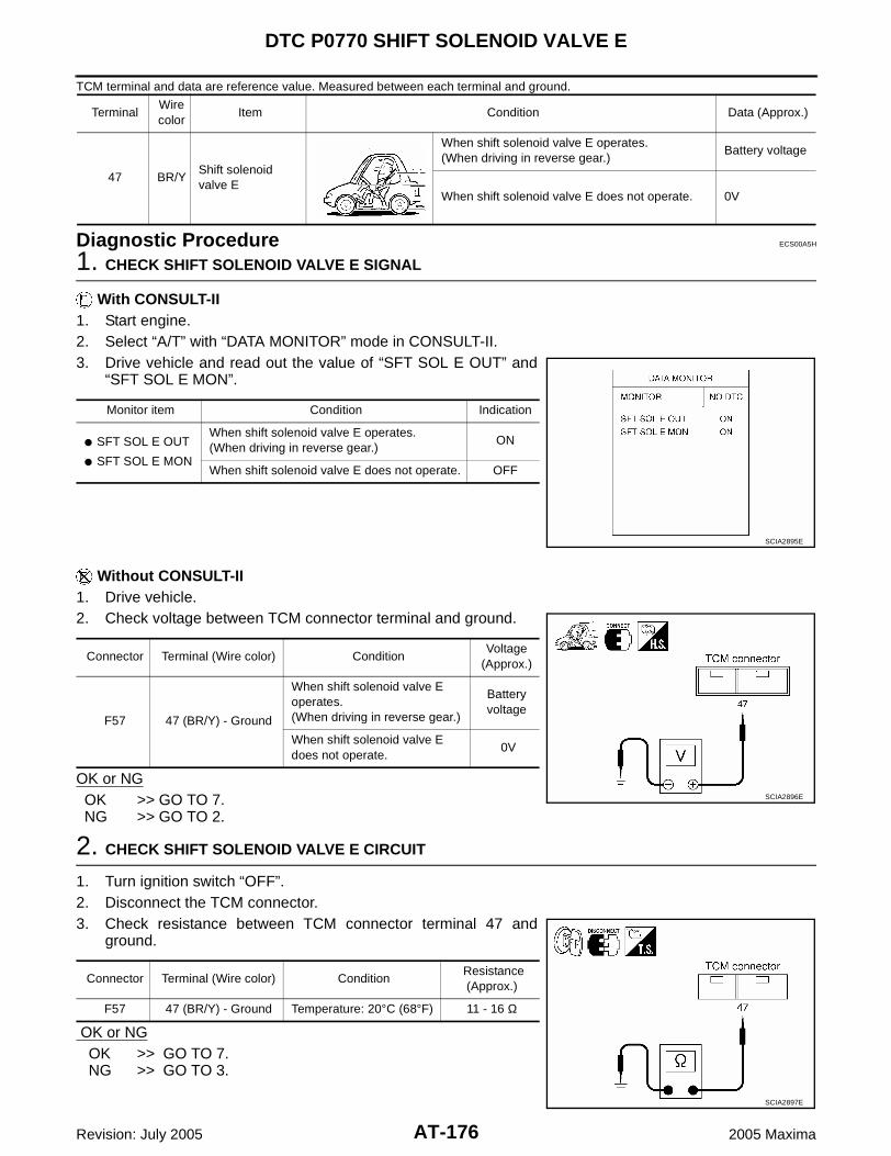
AT-176
DTC P0770 SHIFT SOLENOID VALVE E
Revision: July 2005 2005 Maxima
TCM terminal and data are reference value. Measured between each terminal and ground.
Diagnostic Procedure ECS00A5H
1. CHECK SHIFT SOLENOID VALVE E SIGNAL
With CONSULT-II1. Start engine.2. Select “A/T” with “DATA MONITOR” mode in CONSULT-II.3. Drive vehicle and read out the value of “SFT SOL E OUT” and
“SFT SOL E MON”.
Without CONSULT-II1. Drive vehicle.2. Check voltage between TCM connector terminal and ground.
OK or NGOK >> GO TO 7.NG >> GO TO 2.
2. CHECK SHIFT SOLENOID VALVE E CIRCUIT
1. Turn ignition switch “OFF”.2. Disconnect the TCM connector.3. Check resistance between TCM connector terminal 47 and
ground.
OK or NG OK >> GO TO 7. NG >> GO TO 3.
TerminalWire color
Item Condition Data (Approx.)
47 BR/YShift solenoid valve E
When shift solenoid valve E operates.(When driving in reverse gear.)
Battery voltage
When shift solenoid valve E does not operate. 0V
Monitor item Condition Indication
SFT SOL E OUT
SFT SOL E MON
When shift solenoid valve E operates.(When driving in reverse gear.)
ON
When shift solenoid valve E does not operate. OFF
SCIA2895E
Connector Terminal (Wire color) ConditionVoltage
(Approx.)
F57 47 (BR/Y) - Ground
When shift solenoid valve E operates.(When driving in reverse gear.)
Battery voltage
When shift solenoid valve E does not operate.
0V
SCIA2896E
Connector Terminal (Wire color) Condition Resistance (Approx.)
F57 47 (BR/Y) - Ground Temperature: 20°C (68°F) 11 - 16 Ω
SCIA2897E
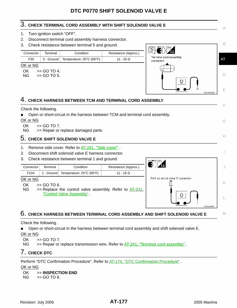
DTC P0770 SHIFT SOLENOID VALVE E
AT-177
D
E
F
G
H
I
J
K
L
M
A
B
AT
Revision: July 2005 2005 Maxima
3. CHECK TERMINAL CORD ASSEMBLY WITH SHIFT SOLENOID VALVE E
1. Turn ignition switch “OFF”.2. Disconnect terminal cord assembly harness connector.3. Check resistance between terminal 5 and ground.
OK or NGOK >> GO TO 4.NG >> GO TO 5.
4. CHECK HARNESS BETWEEN TCM AND TERMINAL CORD ASSEMBLY
Check the following. Open or short-circuit in the harness between TCM and terminal cord assembly.OK or NGOK >> GO TO 7.NG >> Repair or replace damaged parts.
5. CHECK SHIFT SOLENOID VALVE E
1. Remove side cover. Refer to AT-241, "Side cover" .2. Disconnect shift solenoid valve E harness connector.3. Check resistance between terminal 1 and ground.
OK or NGOK >> GO TO 6.NG >> Replace the control valve assembly. Refer to AT-241,
"Control Valve Assembly" .
6. CHECK HARNESS BETWEEN TERMINAL CORD ASSEMBLY AND SHIFT SOLENOID VALVE E
Check the following. Open or short-circuit in the harness between terminal cord assembly and shift solenoid valve E.OK or NGOK >> GO TO 7.NG >> Repair or replace transmission wire. Refer to AT-241, "Terminal cord assembly" .
7. CHECK DTC
Perform “DTC Confirmation Procedure”. Refer to AT-174, "DTC Confirmation Procedure" .OK or NGOK >> INSPECTION ENDNG >> GO TO 8.
Connector Terminal Condition Resistance (Approx.)
F30 5 - Ground Temperature: 20°C (68°F) 11 - 16 Ω
WCIA0452E
Connector Terminal Condition Resistance (Approx.)
F104 1 - Ground Temperature: 20°C (68°F) 11 - 16 Ω
SCIA4340E

AT-178
DTC P0770 SHIFT SOLENOID VALVE E
Revision: July 2005 2005 Maxima
8. CHECK TCM
1. Check TCM input/output signal. Refer to AT-71, "TCM Input/Output Signal Reference Values" .2. If NG, recheck TCM pin terminals for damage or loose connection with harness connector.OK or NGOK >> INSPECTION ENDNG >> Repair or replace damaged parts.
Component Inspection ECS00A5I
SHIFT SOLENOID VALVE E1. Remove side cover. Refer to AT-241, "Side cover" .2. Disconnect shift solenoid valve E harness connector.3. Check resistance between terminal 1 and ground.
4. If NG, replace the control valve assembly. Refer to AT-241,"Control Valve Assembly" .
Connector Terminal Condition Resistance (Approx.)
F104 1 - Ground Temperature: 20°C (68°F) 11 - 16 Ω
SCIA4340E

DTC P0775 PRESSURE CONTROL SOLENOID VALVE B (SHIFT PRESSURE)
AT-179
D
E
F
G
H
I
J
K
L
M
A
B
AT
Revision: July 2005 2005 Maxima
DTC P0775 PRESSURE CONTROL SOLENOID VALVE B (SHIFT PRESSURE)PFP:31940
Description ECS00A5J
The pressure control solenoid valve B is normally high, 3-portlinear pressure control solenoid.
The pressure control solenoid valve B controls linear shift pres-sure by control signal from TCM and controls 2nd coast brakedirectly under 2nd, 3rd, 4th and direct clutch directly under 5thand reverse.
On Board Diagnosis Logic ECS00A5K
This is an OBD-II self-diagnostic item. Diagnostic trouble code “PC SOL B(SFT/PRS)” with CONSULT-II or P0775 without CONSULT-II is
detected under the following conditions.– When normal voltage is not applied to solenoid due to open, short, and so on.– When TCM detects as irregular by comparing target value with monitor value.
Possible Cause ECS00A5L
Harness or connectors(The solenoid circuit is open or shorted.)
Pressure control solenoid valve B
DTC Confirmation Procedure ECS00A5M
NOTE:If “DTC Confirmation Procedure” has been previously performed, always turn ignition switch “OFF”and wait at least 10 seconds before performing the next test.After the repair, perform the following procedure to confirm the malfunction is eliminated.
WITH CONSULT-II1. Turn ignition switch “ON”. (Do not start engine.)2. Select “A/T” with “DATA MONITOR” mode in CONSULT-II.3. Start engine.4. Run engine for at least 13 consecutive seconds at idle speed.5. If DTC is detected, go to AT-181, "Diagnostic Procedure" .
WITH GSTFollow the procedure “With CONSULT-II”.
SCIA2831E
BCIA0030E
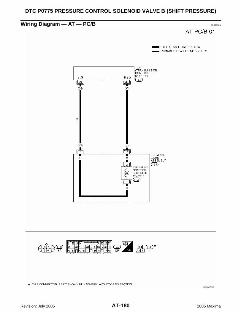
AT-180
DTC P0775 PRESSURE CONTROL SOLENOID VALVE B (SHIFT PRESSURE)
Revision: July 2005 2005 Maxima
Wiring Diagram — AT — PC/B ECS00A5N
BCWA0287E

DTC P0775 PRESSURE CONTROL SOLENOID VALVE B (SHIFT PRESSURE)
AT-181
D
E
F
G
H
I
J
K
L
M
A
B
AT
Revision: July 2005 2005 Maxima
TCM terminals and data are reference value. Measured between each terminal and ground.
Diagnostic Procedure ECS00A5O
1. CHECK PRESSURE CONTROL SOLENOID VALVE B SIGNAL
With CONSULT-II 1. After warming up the engine and transaxle, turn ignition switch “OFF”.2. Turn ignition switch “ON”. (Do not start engine.)3. Select “DATA MONITOR” mode for “A/T” with CONSULT-II.4. Read out the value of “PC SOL B OUT” and “PC SOL B MON”.
Without CONSULT-II1. Start the engine.2. Check pulse between TCM connector terminals 21 and 36.
OK or NGOK >> GO TO 7.NG >> GO TO 2.
2. CHECK PRESSURE CONTROL SOLENOID VALVE B CIRCUIT
1. Turn ignition switch “OFF”.2. Disconnect the TCM connector.3. Check resistance between TCM connector terminals 21 and 36.
OK or NG OK >> GO TO 7. NG >> GO TO 3.
TerminalWire color
Item Condition Data (Approx.)
21 G/BPressure control solenoid valve B ground
When engine is running with idle speed and set-ting selector lever to “P” position.
0V
36 O/BPressure control solenoid valve B
When engine is running with idle speed and set-ting selector lever to “P” position.
300Hz
Monitor item ConditionDisplay value
(Approx.)
PC SOL B OUT
PC SOL B MON
Selector lever: Manual shift gate position 1.00 A
Other than the above. 0.30 A
SCIA2907E
Connector Terminal (Wire color) ConditionData
(Approx.)
F5736 (O/B) - 21 (G/B)
(Ground)
When engine is running with idle speed and setting selector lever to “P” position.
300 Hz
SCIA2911E
Connector Terminal (Wire color) Condition Resistance
(Approx.)
F5736 (O/B) - 21 (G/B)
(Ground)Temperature: 20°C (68°F) 5.0 - 5.6 Ω
SCIA2912E

AT-182
DTC P0775 PRESSURE CONTROL SOLENOID VALVE B (SHIFT PRESSURE)
Revision: July 2005 2005 Maxima
3. CHECK TERMINAL CORD ASSEMBLY WITH PRESSURE CONTROL SOLENOID VALVE B
1. Turn ignition switch “OFF”.2. Disconnect terminal cord assembly harness connector.3. Check resistance between terminals 3 and 7.
OK or NGOK >> GO TO 4.NG >> GO TO 5.
4. CHECK HARNESS BETWEEN TCM AND TERMINAL CORD ASSEMBLY
Check the following. Open or short-circuit in the harness between TCM and terminal cord assembly.OK or NGOK >> GO TO 7.NG >> Repair or replace damaged parts.
5. CHECK PRESSURE CONTROL SOLENOID VALVE B
1. Remove side cover. Refer to AT-241, "Side cover" .2. Disconnect pressure control solenoid valve B harness connector.3. Check resistance between terminals 1 and 2.
OK or NGOK >> GO TO 6.NG >> Replace the control valve assembly. Refer to AT-241,
"Control Valve Assembly" .
6. CHECK HARNESS BETWEEN TERMINAL CORD ASSEMBLY AND PRESSURE CONTROL SOLE-NOID VALVE B
Check the following. Open or short-circuit in the harness between terminal cord assembly and pressure control solenoid valve
B.OK or NGOK >> GO TO 7.NG >> Repair or replace transmission wire. Refer to AT-241, "Terminal cord assembly" .
7. CHECK DTC
Perform “DTC Confirmation Procedure”. Refer to AT-179, "DTC Confirmation Procedure" .OK or NGOK >> INSPECTION ENDNG >> GO TO 8.
Connector Terminal Condition Resistance (Approx.)
F62 3 - 7 Temperature: 20°C (68°F) 5.0 - 5.6 Ω
SCIA2913E
Connector Terminal Condition Resistance (Approx.)
F106 1 - 2 Temperature: 20°C (68°F) 5.0 - 5.6 Ω
SCIA4341E

DTC P0775 PRESSURE CONTROL SOLENOID VALVE B (SHIFT PRESSURE)
AT-183
D
E
F
G
H
I
J
K
L
M
A
B
AT
Revision: July 2005 2005 Maxima
8. CHECK TCM
1. Check TCM input/output signal. Refer to AT-71, "TCM Input/Output Signal Reference Values" .2. If NG, recheck TCM pin terminals for damage or loose connection with harness connector.OK or NGOK >> INSPECTION ENDNG >> Repair or replace damaged parts.
Component Inspection ECS00A5P
PRESSURE CONTROL SOLENOID VALVE B1. Remove side cover. Refer to AT-241, "Side cover" .2. Disconnect pressure control solenoid valve B harness connector.3. Check resistance between terminals 1 and 2.
4. If NG, replace the control valve assembly. Refer to AT-241,"Control Valve Assembly" .
Connector Terminal Condition Resistance (Approx.)
F106 1 - 2 Temperature: 20°C (68°F) 5.0 - 5.6 Ω
SCIA4341E

AT-184
DTC P0780 SHIFT
Revision: July 2005 2005 Maxima
DTC P0780 SHIFT PFP:31940
Description ECS00A5Q
This malfunction will not be detected while the A/T CHECK indicator lamp is indicating another self-diag-nosis malfunction.
This malfunction is detected when the A/T does not shift as instructed by the TCM. This is not caused byelectrical malfunction (circuits open or shorted) but by mechanical malfunction such as control valve stick-ing, improper solenoid valve operation, etc.
On Board Diagnosis Logic ECS00A5R
This is an OBD-II self-diagnostic item. Diagnostic trouble code “SHIFT” with CONSULT-II or P0780 without CONSULT-II is detected under the
following conditions.– When no rotation change occurs between input (turbine revolution sensor) and output (revolution sensor)
and shifting time is long.– When shifting ends immediately.– When engine revs up unusually during shifting.
Possible Cause ECS00A5S
Shift solenoid valve D(Off error.)
Shift solenoid valve E(Off error.)
Pressure control solenoid valve A(On/Off error.)
Pressure control solenoid valve B(On/Off error.)
Pressure control solenoid valve C(On/Off error.)
Hydraulic control circuit
DTC Confirmation Procedure ECS00A5T
CAUTION: Always drive vehicle at a safe speed. Be careful not to rev engine into the red zone on the tachometer.NOTE:If “DTC Confirmation Procedure” has been previously performed, always turn ignition switch “OFF”and wait at least 10 seconds before performing the next test.After the repair, perform the following procedure to confirm the malfunction is eliminated.
WITH CONSULT-II1. Start engine and select “A/T” with “DATA MONITOR” mode in
CONSULT-II.2. Make sure that ATF temperature is within the range below.
FLUID TEMP: More than 60°C (140°F)If out of range, drive the vehicle to warm up the fluid.
3. Drive vehicle and allow the following conditions.SLCT LVR POSI: “D” positionGEAR: 1st 2nd 3rd 4th 5th position(Vehicle speed: Refer to AT-312, "VEHICLE SPEED WHENSHIFTING GEARS" .)
4. If DTC is detected, go to AT-187, "Diagnostic Procedure" .
WITH GSTFollow the procedure “With CONSULT-II”.
BCIA0030E

DTC P0780 SHIFT
AT-185
D
E
F
G
H
I
J
K
L
M
A
B
AT
Revision: July 2005 2005 Maxima
Wiring Diagram — AT — SFTFNC ECS00A5U
BCWA0288E

AT-186
DTC P0780 SHIFT
Revision: July 2005 2005 Maxima
BCWA0289E

DTC P0780 SHIFT
AT-187
D
E
F
G
H
I
J
K
L
M
A
B
AT
Revision: July 2005 2005 Maxima
TCM terminals and data are reference value. Measured between each terminal and ground.
Diagnostic Procedure ECS00A5V
1. CHECK EACH SHIFT SOLENOID VALVE CIRCUIT
Perform “Diagnostic Procedure” for the following DTCs. “DTC P0765 SHIFT SOLENOID VALVE D” (Refer to AT-171, "Diagnostic Procedure" .) “DTC P0770 SHIFT SOLENOID VALVE E” (Refer to AT-176, "Diagnostic Procedure" .)OK or NGOK >> GO TO 2.NG >> Repair or replace damaged parts.
2. CHECK EACH PRESSURE CONTROL SOLENOID VALVE CIRCUIT
Perform “Diagnostic Procedure” for the following DTCs. “DTC P0745 PRESSURE CONTROL SOLENOID VALVE A” (Refer to AT-146, "Diagnostic Procedure" .) “DTC P0775 PRESSURE CONTROL SOLENOID VALVE B” (Refer to AT-181, "Diagnostic Procedure" .) “DTC P0795 PRESSURE CONTROL SOLENOID VALVE C” (Refer to AT-190, "Diagnostic Procedure" .)OK or NGOK >> GO TO 3.NG >> Repair or replace damaged parts.
3. CHECK DTC
Perform “DTC Confirmation Procedure”. Refer to AT-184, "DTC Confirmation Procedure" .OK or NGOK >> INSPECTION ENDNG >> Replace the control valve assembly. Refer to AT-241, "Control Valve Assembly" .
TerminalWire color
Item Condition Data (Approx.)
21 G/BPressure control solenoid valve B ground
When engine is running with idle speed and set-ting selector lever to “P” position.
0V
26 V/WShift solenoid valve D
When shift solenoid valve D operates.(When driving in 3rd, 4th or 5th gear.)
Battery voltage
When shift solenoid valve D does not operate. 0V
28 WPressure control solenoid valve C ground
When engine is running with idle speed and set-ting selector lever to “P” position.
0V
35 L/YPressure control solenoid valve A
When engine is running with idle speed and set-ting selector lever to “P” position.
300Hz
36 O/BPressure control solenoid valve B
When engine is running with idle speed and set-ting selector lever to “P” position.
300Hz
40 L/GPressure control solenoid valve A ground
When engine is running with idle speed and set-ting selector lever to “P” position.
0V
45 OPressure control solenoid valve C
When engine is running with idle speed and set-ting selector lever to “P” position.
300Hz
47 BR/YShift solenoid valve E
When shift solenoid valve E operates.(When driving in reverse gear.)
Battery voltage
When shift solenoid valve E does not operate. 0V

AT-188
DTC P0795 PRESSURE CONTROL SOLENOID VALVE C (TCC AND SHIFT PRESSURE)
Revision: July 2005 2005 Maxima
DTC P0795 PRESSURE CONTROL SOLENOID VALVE C (TCC AND SHIFT PRES-SURE) PFP:31940
Description ECS00A5W
The pressure control solenoid valve C is normally low, 3-port lin-ear pressure control solenoid.
The pressure control solenoid valve C is activated to control theapply and release of the 2nd brake and 1st and reverse brake,and torque converter clutch.
Lock-up operation, however, is prohibited when A/T fluid tem-perature is too low.
When the accelerator pedal is depressed (less than 1/8) in lock-up condition, the engine speed should not change abruptly. Ifthere is a big jump in engine speed, there is no lock-up.
On Board Diagnosis Logic ECS00A5X
This is an OBD-II self-diagnostic item. Diagnostic trouble code “PC SOL C(TCC&SFT)” with CONSULT-II or P0795 without CONSULT-II is
detected under the following conditions.– When normal voltage is not applied to solenoid due to open, short, and so on.– When TCM detects as irregular by comparing target value with monitor value.
Possible Cause ECS00A5Y
Harness or connectors(The solenoid circuit is open or shorted.)
Pressure control solenoid valve C
DTC Confirmation Procedure ECS00A5Z
NOTE:If “DTC Confirmation Procedure” has been previously performed, always turn ignition switch “OFF”and wait at least 10 seconds before performing the next test.After the repair, perform the following procedure to confirm the malfunction is eliminated.
WITH CONSULT-II1. Turn ignition switch “ON”. (Do not start engine.)2. Select “A/T” with “DATA MONITOR” mode in CONSULT-II.3. Start engine.4. Run engine for at least 13 consecutive seconds at idle speed.5. If DTC is detected, go to AT-190, "Diagnostic Procedure" .
WITH GSTFollow the procedure “With CONSULT-II”.
SCIA2833E
BCIA0030E

DTC P0795 PRESSURE CONTROL SOLENOID VALVE C (TCC AND SHIFT PRESSURE)
AT-189
D
E
F
G
H
I
J
K
L
M
A
B
AT
Revision: July 2005 2005 Maxima
Wiring Diagram — AT — PC/C ECS00A60
BCWA0290E

AT-190
DTC P0795 PRESSURE CONTROL SOLENOID VALVE C (TCC AND SHIFT PRESSURE)
Revision: July 2005 2005 Maxima
TCM terminals and data are reference value. Measured between each terminal and ground.
Diagnostic Procedure ECS00A61
1. CHECK PRESSURE CONTROL SOLENOID VALVE C SIGNAL
With CONSULT-II1. After warming up the engine and transaxle, turn ignition switch “OFF”.2. Turn ignition switch “ON”. (Do not start engine.)3. Select “A/T” with “DATA MONITOR” mode in CONSULT-II.4. Read out the value of “PC SOL C OUT” and “PC SOL C MON”.
Without CONSULT-II1. Start the engine.2. Check pulse between TCM connector terminals 28 and 45.
OK or NGOK >> GO TO 7.NG >> GO TO 2.
2. CHECK PRESSURE CONTROL SOLENOID VALVE C CIRCUIT
1. Turn ignition switch “OFF”.2. Disconnect the TCM connector.3. Check resistance between TCM connector terminals 28 and 45.
OK or NG OK >> GO TO 7. NG >> GO TO 3.
TerminalWire color
Item Condition Data (Approx.)
28 WPressure control solenoid valve C ground
When engine is running with idle speed and set-ting selector lever to “P” position.
0V
45 OPressure control solenoid valve C
When engine is running with idle speed and set-ting selector lever to “P” position.
300Hz
Monitor item ConditionDisplay value
(Approx.)
PC SOL C OUT
PC SOL C MON
Selector lever: Manual shift gate position 1.00 A
Other than the above. 0.20 A
SCIA2907E
Connector Terminal (Wire color) ConditionData
(Approx.)
F5745 (O) - 28 (W)
(Ground)
When engine is running with idle speed and setting selector lever to “P” position.
300 Hz
SCIA2914E
Connector Terminal (Wire color) Condition Resistance (Approx.)
F5745 (O) - 28 (W)
(Ground)Temperature: 20°C (68°F) 5.0 - 5.6 Ω
SCIA2915E

DTC P0795 PRESSURE CONTROL SOLENOID VALVE C (TCC AND SHIFT PRESSURE)
AT-191
D
E
F
G
H
I
J
K
L
M
A
B
AT
Revision: July 2005 2005 Maxima
3. CHECK TERMINAL CORD ASSEMBLY WITH PRESSURE CONTROL SOLENOID VALVE C
1. Turn ignition switch “OFF”.2. Disconnect terminal cord assembly harness connector.3. Check resistance between terminals 2 and 5.
OK or NGOK >> GO TO 4.NG >> GO TO 5.
4. CHECK HARNESS BETWEEN TCM AND TERMINAL CORD ASSEMBLY
Check the following. Open or short-circuit in the harness between TCM and terminal cord assembly.OK or NGOK >> GO TO 7.NG >> Repair or replace damaged parts.
5. CHECK PRESSURE CONTROL SOLENOID VALVE C
1. Remove side cover. Refer to AT-241, "Side cover" .2. Disconnect pressure control solenoid valve C harness connector.3. Check resistance between terminals 1 and 2.
OK or NGOK >> GO TO 6.NG >> Replace the control valve assembly. Refer to AT-241,
"Control Valve Assembly" .
6. CHECK HARNESS BETWEEN TERMINAL CORD ASSEMBLY AND PRESSURE CONTROL SOLE-NOID VALVE C
Check the following. Open or short-circuit in the harness between terminal cord assembly and pressure control solenoid valve
C.OK or NGOK >> GO TO 7.NG >> Repair or replace transmission wire. Refer to AT-241, "Terminal cord assembly" .
7. CHECK DTC
Perform “DTC Confirmation Procedure”. Refer to AT-188, "DTC Confirmation Procedure" .OK or NGOK >> INSPECTION ENDNG >> GO TO 8.
Connector Terminal Condition Resistance (Approx.)
F62 2 - 5 Temperature: 20°C (68°F) 5.0 - 5.6 Ω
SCIA2916E
Connector Terminal Condition Resistance (Approx.)
F107 1 - 2 Temperature: 20°C (68°F) 5.0 - 5.6 Ω
SCIA4342E

AT-192
DTC P0795 PRESSURE CONTROL SOLENOID VALVE C (TCC AND SHIFT PRESSURE)
Revision: July 2005 2005 Maxima
8. CHECK TCM
1. Check TCM input/output signal. Refer to AT-71, "TCM Input/Output Signal Reference Values" .2. If NG, recheck TCM pin terminals for damage or loose connection with harness connector.OK or NGOK >> INSPECTION ENDNG >> Repair or replace damaged parts.
Component Inspection ECS00A62
PRESSURE CONTROL SOLENOID VALVE C1. Remove side cover. Refer to AT-241, "Side cover" .2. Disconnect pressure control solenoid valve C harness connector.3. Check resistance between terminals 1 and 2.
4. If NG, replace the control valve assembly. Refer to AT-241,"Control Valve Assembly" .
Connector Terminal Condition Resistance (Approx.)
F107 1 - 2 Temperature: 20°C (68°F) 5.0 - 5.6 Ω
SCIA4342E

DTC P0797 PRESSURE CONTROL SOLENOID VALVE C STUCK ON
AT-193
D
E
F
G
H
I
J
K
L
M
A
B
AT
Revision: July 2005 2005 Maxima
DTC P0797 PRESSURE CONTROL SOLENOID VALVE C STUCK ON PFP:31940
Description ECS00A63
This malfunction will not be detected while the A/T CHECK indicator lamp is indicating another self-diag-nosis malfunction.
This is not caused by electrical malfunction (circuits open or shorted) but by mechanical malfunction suchas control valve sticking, improper solenoid valve operation, etc.
The pressure control solenoid valve C is normally low, 3-port lin-ear pressure control solenoid.
The pressure control solenoid valve C is activated to control theapply and release of the 2nd brake and 1st and reverse brake,and torque converter clutch.
Lock-up operation, however, is prohibited when A/T fluid tem-perature is too low.
When the accelerator pedal is depressed (less than 1/8) in lock-up condition, the engine speed should not change abruptly. Ifthere is a big jump in engine speed, there is no lock-up.
On Board Diagnosis Logic ECS00A64
This is an OBD-II self-diagnostic item. Diagnostic trouble code “PC SOL C STC ON” with CONSULT-II or P0797 without CONSULT-II is detected
when condition of pressure control solenoid valve C is different from monitor value, and relation betweengear position and actual gear ratio or lock-up status is irregular.
Possible Cause ECS00A65
Pressure control solenoid valve C(On stick.)
Hydraulic control circuit
DTC Confirmation Procedure ECS00A66
NOTE:If “DTC Confirmation Procedure” has been previously performed, always turn ignition switch “OFF”and wait at least 10 seconds before performing the next test.After the repair, perform the following procedure to confirm the malfunction is eliminated.
WITH CONSULT-II1. Turn ignition switch “ON”. (Do not start engine.)2. Select “A/T” with “DATA MONITOR” mode in CONSULT-II.3. Start engine.4. Run engine for at least 4 consecutive minutes at idle speed.5. If DTC is detected, go to AT-195, "Diagnostic Procedure" .
WITH GSTFollow the procedure “With CONSULT-II”.
SCIA2833E
BCIA0030E

AT-194
DTC P0797 PRESSURE CONTROL SOLENOID VALVE C STUCK ON
Revision: July 2005 2005 Maxima
Wiring Diagram — AT — PC/CS ECS00A67
BCWA0291E

DTC P0797 PRESSURE CONTROL SOLENOID VALVE C STUCK ON
AT-195
D
E
F
G
H
I
J
K
L
M
A
B
AT
Revision: July 2005 2005 Maxima
TCM terminals and data are reference value. Measured between each terminal and ground.
Diagnostic Procedure ECS00A68
1. CHECK PRESSURE CONTROL SOLENOID VALVE C SIGNAL
With CONSULT-II1. After warming up the engine and transaxle, turn ignition switch “OFF”.2. Turn ignition switch “ON”. (Do not start engine.)3. Select “A/T” with “DATA MONITOR” mode in CONSULT-II. 4. Read out the value of “PC SOL C OUT” and “PC SOL C MON”.
Without CONSULT-II1. Start the engine.2. Check pulse between TCM connector terminals 28 and 45.
OK or NGOK >> GO TO 7.NG >> GO TO 2.
2. CHECK PRESSURE CONTROL SOLENOID VALVE C CIRCUIT
1. Turn ignition switch “OFF”.2. Disconnect the TCM connector.3. Check resistance between TCM connector terminals 28 and 45.
OK or NG OK >> GO TO 7. NG >> GO TO 3.
TerminalWire color
Item Condition Data (Approx.)
28 WPressure control solenoid valve C ground
When engine is running with idle speed and set-ting selector lever to “P” position.
0V
45 OPressure control solenoid valve C
When engine is running with idle speed and set-ting selector lever to “P” position.
300Hz
Monitor item ConditionDisplay value
(Approx.)
PC SOL C OUT
PC SOL C MON
Selector lever: Manual shift gate position 1.00 A
Other than the above. 0.20 A
SCIA2907E
Connector Terminal (Wire color) ConditionData
(Approx.)
F5745 (O) - 28 (W)
(Ground)
When engine is running with idle speed and setting selector lever to “P” position.
300 Hz
SCIA2914E
Connector Terminal (Wire color) Condition Resistance
(Approx.)
F5745 (O) - 28 (W)
(Ground)Temperature: 20°C (68°F) 5.0 - 5.6 Ω
SCIA2915E

AT-196
DTC P0797 PRESSURE CONTROL SOLENOID VALVE C STUCK ON
Revision: July 2005 2005 Maxima
3. CHECK TERMINAL CORD ASSEMBLY WITH PRESSURE CONTROL SOLENOID VALVE C
1. Turn ignition switch “OFF”.2. Disconnect terminal cord assembly harness connector.3. Check resistance between terminals 2 and 5.
OK or NGOK >> GO TO 4.NG >> GO TO 5.
4. CHECK HARNESS BETWEEN TCM AND TERMINAL CORD ASSEMBLY
Check the following. Open or short-circuit in the harness between TCM and terminal cord assembly.OK or NGOK >> GO TO 7.NG >> Repair or replace damaged parts.
5. CHECK PRESSURE CONTROL SOLENOID VALVE C
1. Remove side cover. Refer to AT-241, "Side cover" .2. Disconnect pressure control solenoid valve C harness connector.3. Check resistance between terminals 1 and 2.
OK or NGOK >> GO TO 6.NG >> Replace the control valve assembly. Refer to AT-241,
"Control Valve Assembly" .
6. CHECK HARNESS BETWEEN TERMINAL CORD ASSEMBLY AND PRESSURE CONTROL SOLE-NOID VALVE C
Check the following. Open or short-circuit in the harness between terminal cord assembly and pressure control solenoid valve
C.OK or NGOK >> GO TO 7.NG >> Repair or replace transmission wire. Refer to AT-241, "Terminal cord assembly" .
7. CHECK TCM
1. Check TCM input/output signal. Refer to AT-71, "TCM Input/Output Signal Reference Values" .2. If NG, recheck TCM pin terminals for damage or loose connection with harness connector.OK or NGOK >> GO TO 8.NG >> Repair or replace damaged parts.
Connector Terminal Condition Resistance (Approx.)
F62 2 - 5 Temperature: 20°C (68°F) 5.0 - 5.6 Ω
SCIA2916E
Connector Terminal Condition Resistance (Approx.)
F107 1 - 2 Temperature: 20°C (68°F) 5.0 - 5.6 Ω
SCIA4342E

DTC P0797 PRESSURE CONTROL SOLENOID VALVE C STUCK ON
AT-197
D
E
F
G
H
I
J
K
L
M
A
B
AT
Revision: July 2005 2005 Maxima
8. CHECK DTC
Perform “DTC Confirmation Procedure”. Refer to AT-193, "DTC Confirmation Procedure" .OK or NGOK >> INSPECTION ENDNG >> Replace the control valve assembly. Refer to AT-241, "Control Valve Assembly" .
Component Inspection ECS00A69
PRESSURE CONTROL SOLENOID VALVE C1. Remove side cover. Refer to AT-241, "Side cover" .2. Disconnect pressure control solenoid valve C harness connector.3. Check resistance between terminals 1 and 2.
4. If NG, replace the control valve assembly. Refer to AT-241,"Control Valve Assembly" .
Connector Terminal Condition Resistance (Approx.)
F107 1 - 2 Temperature: 20°C (68°F) 5.0 - 5.6 Ω
SCIA4342E

AT-198
DTC P0826 MANUAL MODE SWITCH CIRCUIT
Revision: July 2005 2005 Maxima
DTC P0826 MANUAL MODE SWITCH CIRCUIT PFP:34901
Description ECS00A6A
Manual mode switch is installed in A/T device. It sends manual mode switch, shift up and shift down switchsignals to TCM.TCM sends the switch signals to unified meter and A/C amp. by CAN communication line. Then manual modeswitch position is indicated on the A/T indicator. For inspection, refer to AT-203, "Position Indicator" .
CONSULT-II Reference Value in Data Monitor Mode ECS00A6B
On Board Diagnosis Logic ECS00A6C
This is not an OBD-II self-diagnostic item. Diagnostic trouble code “MANUAL MODE SWITCH” with CONSULT-II is detected when TCM monitors
manual mode, non manual mode, up or down switch signals, and judges as irregular when impossibleinput pattern occurs.
Possible Cause ECS00A6D
Harness or connectors(These switches circuit is open or shorted.)
Manual mode switch (built into A/T device)
DTC Confirmation Procedure ECS00A6E
NOTE:If “DTC Confirmation Procedure” has been previously performed, always turn ignition switch “OFF”and wait at least 10 seconds before performing the next test.After the repair, perform the following procedure to confirm the malfunction is eliminated.
WITH CONSULT-II1. Turn ignition switch “ON”. (Do not start engine.)2. Select “A/T” with “DATA MONITOR” mode in CONSULT-II.3. Move selector lever to “M” position (manual shift gate position).4. Shift selector lever into “+ side” and “- side”.5. Wait for at least 30 consecutive seconds.6. If DTC is detected, go to AT-201, "Diagnostic Procedure" .
Monitor Item Condition Reference Value
MANU MODE SW (ON/OFF)Manual shift gate position (neutral) ON
Other than the above OFF
NON M-MODE SW (ON/OFF)Manual shift gate position OFF
Other than the above ON
UP SW (ON/OFF)Selector lever: + side ON
Other than the above OFF
DOWN SW (ON/OFF)Selector lever: - side ON
Other than the above OFF
BCIA0030E

DTC P0826 MANUAL MODE SWITCH CIRCUIT
AT-199
D
E
F
G
H
I
J
K
L
M
A
B
AT
Revision: July 2005 2005 Maxima
Wiring Diagram — AT — MMSW ECS00A6F
BCWA0479E

AT-200
DTC P0826 MANUAL MODE SWITCH CIRCUIT
Revision: July 2005 2005 Maxima
TCM terminals and data are reference value. Measured between each terminal and ground.
TerminalWire color
Item Condition Data (Approx.)
5 R/GManual mode switch UP (+)
Selector lever: + side 0V
Other than the above Battery voltage
6 L/RManual mode switch DOWN (-)
Selector lever: - side 0V
Other than the above Battery voltage
16 SBManual mode switch AUTO
Selector lever: “P”, “R”, “N” or “D” position 0V
Selector lever: Manual shift gate position Battery voltage
19 V/RManual mode switch MANUAL
Selector lever: Manual shift gate position (neutral) 0V
Other than the above Battery voltage

DTC P0826 MANUAL MODE SWITCH CIRCUIT
AT-201
D
E
F
G
H
I
J
K
L
M
A
B
AT
Revision: July 2005 2005 Maxima
Diagnostic Procedure ECS00A6G
1. CHECK MANUAL MODE SWITCH CIRCUIT
With CONSULT-II1. Turn ignition switch “ON”. (Do not start engine.)2. Select “A/T” with “DATA MONITOR” mode in CONSULT-II.3. Read out ON/OFF switching action of the “MANU MODE SW”,
“NON M-MODE SW”, “UP SW”, “DOWN SW”.
Without CONSULT-II1. Turn ignition switch “ON”. (Do not start engine.)2. Check voltage between the TCM connector terminals and
ground.
OK or NGOK >> GO TO 4. NG >> GO TO 2.
SCIA2917E
Connector No.
Terminal (Wire color)
ConditionVoltage
(Approx.)
F56
5 (R/G) - Ground
Selector lever: + side 0V
Other than the aboveBattery voltage
6 (L/R) - Ground
Selector lever: - side 0V
Other than the aboveBattery voltage
16 (SB) - Ground
Selector lever: “P”, “R”, “N” or “D” posi-tion
0V
Selector lever: Manual shift gate posi-tion
Battery voltage
19 (V/R) - Ground
Selector lever: Manual shift gate posi-tion (neutral)
0V
Other than the aboveBattery voltage
SCIA2918E

AT-202
DTC P0826 MANUAL MODE SWITCH CIRCUIT
Revision: July 2005 2005 Maxima
2. CHECK HARNESS BETWEEN TCM AND A/T DEVICE (MANUAL MODE SWITCH)
1. Turn ignition switch “OFF”.2. Disconnect the TCM connector.3. Check the continuity between TCM connector terminals 5, 6, 16,
19 and ground.
4. If OK, check harness for short-circuit to ground or power source.OK or NGOK >> GO TO 4.NG >> GO TO 3.
3. DETECT MALFUNCTIONING ITEM
Check the following. Open or short-circuit in the harness between TCM and A/T device (manual mode switch). Open or short-circuit in the harness for ground of manual mode switch. Manual mode switch. Refer to AT-203, "Component Inspection" .OK or NGOK >> GO TO 4.NG >> Repair or replace damaged parts.
4. CHECK DTC
Perform “DTC Confirmation Procedure”. Refer to AT-198, "DTC Confirmation Procedure" .OK or NGOK >> INSPECTION ENDNG >> GO TO 5.
5. CHECK TCM
1. Check TCM input/output signal. Refer to AT-71, "TCM Input/Output Signal Reference Values" .2. If NG, recheck TCM pin terminals for damage or loose connection with harness connector.OK or NGOK >> INSPECTION ENDNG >> Repair or replace damaged parts.
Connector No.
Terminal (Wire color)
Condition Continuity
F56
5 (R/G) - Ground
Selector lever: + side Yes
Other than the above No
6 (L/R) - Ground
Selector lever: - side Yes
Other than the above No
16 (SB) - Ground
Selector lever: “P”, “R”, “N” or “D” posi-tion
Yes
Selector lever: Manual shift gate posi-tion
No
19 (V/R) - Ground
Selector lever: Manual shift gate posi-tion (neutral)
Yes
Other than the above No
SCIA2919E

DTC P0826 MANUAL MODE SWITCH CIRCUIT
AT-203
D
E
F
G
H
I
J
K
L
M
A
B
AT
Revision: July 2005 2005 Maxima
Component Inspection ECS00A6H
MANUAL MODE SWITCHCheck continuity between terminals.
Position Indicator ECS00A6I
DIAGNOSTIC PROCEDURE
1. CHECK INPUT SIGNALS (WITH CONSULT-II)
With CONSULT-II1. Start engine.2. Select “A/T” with “DATA MONITOR” mode in CONSULT-II and
read out the value of “MANU GR POSI”.3. Drive vehicle in the manual mode, and make sure that the actual
gear position and the meter's indication of the position mutuallycoincide when the selector lever is shifted to the “+ (up)” or “-(down)” side (1st ⇔ 5th gear).
OK or NGOK >> INSPECTION ENDNG >> GO TO 2.
2. CHECK DTC WITH TCM
Perform self-diagnosis of TCM. Refer to AT-75, "SELF-DIAG RESULT MODE" . OK or NGOK >> Check combination meter. Refer to DI-50, "A/T INDICATOR" .NG >> Check the malfunctioning system.
Item Position ConnectorTerminal
(Unit side)Continuity
Manual mode (select) switch
Auto
M34
11 - 12
YesManual 3 - 11
UP switch UP 8 - 11
DOWN switch DOWN 7 - 11
WCIA0454E
SCIA2920E

AT-204
DTC P0882 TCM POWER INPUT SIGNAL
Revision: July 2005 2005 Maxima
DTC P0882 TCM POWER INPUT SIGNAL PFP:31036
Description ECS00A6J
When the power supply to the TCM is cut “OFF”, for example because the battery is removed, and the self-diagnostics memory function stops, malfunction is detected.
On Board Diagnosis Logic ECS00A6K
This is an OBD-II self-diagnostic item. Diagnostic trouble code “TCM POWER INPT SIG” with CONSULT-II or P0882 without CONSULT-II is
detected when voltage supplied to TCM is too low.
Possible Cause ECS00A6L
Harness or connectors(Battery or ignition switch and TCM circuit is open or shorted.)
A/T PV IGN relay
DTC Confirmation Procedure ECS00A6M
CAUTION: Always drive vehicle at a safe speed. Be careful not to rev engine into the red zone on the tachometer.NOTE:If “DTC Confirmation Procedure” has been previously performed, always turn ignition switch “OFF”and wait at least 10 seconds before performing the next test.After the repair, perform the following procedure to confirm the malfunction is eliminated.
WITH CONSULT-II1. Turn ignition switch “ON”. (Do not start engine.)2. Select “A/T” with “DATA MONITOR” mode in CONSULT-II.3. Start engine.4. Depress accelerator pedal or drive vehicle and maintain the fol-
lowing condition for at least 20 consecutive seconds.TURBINE REV: More than 800 rpm
5. If DTC is detected, go to AT-207, "Diagnostic Procedure" .
BCIA0030E

DTC P0882 TCM POWER INPUT SIGNAL
AT-205
D
E
F
G
H
I
J
K
L
M
A
B
AT
Revision: July 2005 2005 Maxima
Wiring Diagram — AT — PWR/IN ECS00A6N
BCWA0466E

AT-206
DTC P0882 TCM POWER INPUT SIGNAL
Revision: July 2005 2005 Maxima
TCM terminals and data are reference value. Measured between each terminal and ground.
TerminalWire color
Item Condition Data (Approx.)
1 L/B A/T PV IGN relay
When turning ignition switch ON. 0 - 1.5V
When turning ignition switch OFF. 0V
14 B Ground Always 0V
27 Y/RPower supply(Memory back-up)
When turning ignition switch ON. Battery voltage
When turning ignition switch OFF. Battery voltage
34 Y Power supply
When turning ignition switch ON. Battery voltage
When turning ignition switch OFF. 0V
38 R/YPower supply(A/T PV IGN relay)
When turning ignition switch ON. Battery voltage
Measure 3 seconds after switching “OFF” the ignition switch.
0V
39 R/YPower supply(A/T PV IGN relay)
When turning ignition switch ON. Battery voltage
Measure 3 seconds after switching “OFF” the ignition switch.
0V
48 B Ground Always 0V

DTC P0882 TCM POWER INPUT SIGNAL
AT-207
D
E
F
G
H
I
J
K
L
M
A
B
AT
Revision: July 2005 2005 Maxima
Diagnostic Procedure ECS00A6O
1. CHECK TCM POWER SOURCE CIRCUIT
1. Turn ignition switch “ON”. (Do not start engine.)2. Check voltage between TCM terminals and ground.
3. Turn ignition switch “OFF”.4. Check voltage between TCM terminals and ground.
OK or NGOK >> GO TO 3.NG >> GO TO 2.
2. DETECT MALFUNCTIONING ITEM
Check the following: Harness for short or open between battery and TCM terminal 27 Harness for short or open between ignition switch and TCM terminals 1, 34, 38 and 39 10A fuse [No. 19, located in the fuse block (J/B) or No. 48, located in the IPDM E/R] Ignition switch. Refer to PG-4, "POWER SUPPLY ROUTING CIRCUIT" A/T PV IGN relay. Refer to AT-208, "Component Inspection"OK or NGOK >> GO TO 3.NG >> Repair or replace damaged parts.
3. CHECK TCM GROUND CIRCUIT
1. Turn ignition switch “OFF”.2. Disconnect TCM harness connector.3. Check continuity between TCM terminals 14 (B), 48 (B) and
ground.
If OK, check harness for short to ground and short to power.OK or NGOK >> GO TO 4.NG >> Repair open circuit or short to ground or short to power
in harness or connectors.
Connector Terminal (Wire color) Voltage (Approx.)
F56 1 (L/B) - Ground 0 - 1.5V
F57
27 (Y/R) - Ground
Battery voltage34 (Y) - Ground
38 (R/Y) - Ground
39 (R/Y) - Ground
Connector Terminal (Wire color) Voltage (Approx.)
F56 1 (L/B) - Ground 0V
F57
27 (Y/R) - Ground Battery voltage
34 (Y) - Ground 0V
38 (R/Y) - Ground 0V
39 (R/Y) - Ground 0V
SCIA2930E
Continuity should exist.
SCIA2933E

AT-208
DTC P0882 TCM POWER INPUT SIGNAL
Revision: July 2005 2005 Maxima
4. CHECK DTC
Check again. Refer to AT-204, "DTC Confirmation Procedure" .OK or NGOK >> INSPECTION ENDNG >> GO TO 5.
5. CHECK TCM
1. Check TCM input/output signal. Refer to AT-71, "TCM Input/Output Signal Reference Values" .2. If NG, recheck TCM pin terminals for damage or loose connection with harness connector.OK or NGOK >> INSPECTION ENDNG >> Repair or replace damaged parts.
Component Inspection ECS00A6P
A/T PV IGN RELAY1. Apply 12V direct current between A/T PV IGN relay terminals 1
and 2.2. Check continuity between relay terminals 3 and 5.
3. If NG, replace A/T PV IGN relay.
Condition Continuity
12V direct current supply between terminals 1 and 2 Yes
OFF No
SCIA1245E

DTC P1726 ELECTRIC THROTTLE CONTROL SYSTEM
AT-209
D
E
F
G
H
I
J
K
L
M
A
B
AT
Revision: July 2005 2005 Maxima
DTC P1726 ELECTRIC THROTTLE CONTROL SYSTEM PFP:23710
Description ECS00A6Q
This DTC is displayed with other DTCs regarding ECM. Perform the trouble diagnosis for other DTCs dis-played. Refer to AT-44, "TROUBLE DIAGNOSIS" .When this DTC is detected, lock-up operation and learning control are canceled.

AT-210
TROUBLE DIAGNOSIS FOR SYMPTOMS
Revision: July 2005 2005 Maxima
TROUBLE DIAGNOSIS FOR SYMPTOMS PFP:00007
A/T CHECK Indicator Lamp does not come on ECS00A6R
SYMPTOM:A/T CHECK indicator lamp does not come on for about 2 seconds when turning ignition switch to“ON”.
DIAGNOSTIC PROCEDURE
1. CHECK CAN COMMUNICATION LINE
Perform the self-diagnosis. Is a malfunction in the CAN communication indicated in the results?YES or NOYES >> Check the CAN communication line. Refer to AT-83, "DTC U1000 CAN COMMUNICATION LINE"
.NO >> GO TO 2.
2. CHECK TCM POWER SOURCE CIRCUIT
1. Turn ignition switch “ON”. (Do not start engine.)2. Check voltage between TCM connector terminals and ground.
Refer to AT-205, "Wiring Diagram — AT — PWR/IN" .
3. Turn ignition switch “OFF”.4. Check voltage between TCM connector terminals and ground. Refer to AT-205, "Wiring Diagram — AT —
PWR/IN" .
OK or NGOK >> GO TO 4.NG >> GO TO 3.
3. DETECT MALFUNCTIONING ITEM
Check the following: Harness for short or open between battery and TCM terminal 27 Harness for short or open between ignition switch and TCM terminals 1, 34, 38 and 39 10A fuse [No. 19, located in the fuse block (J/B) or No. 48, located in the IPDM E/R] Ignition switch. Refer to PG-4, "POWER SUPPLY ROUTING CIRCUIT" . A/T PV IGN relay. Refer to AT-208, "Component Inspection" .OK or NGOK >> GO TO 4.NG >> Repair or replace damaged parts.
Connector Terminal (Wire color) Voltage (Approx.)
F56 1 (L/B) - Ground 0 - 1.5V
F57
27 (Y/R) - Ground
Battery voltage34 (Y) - Ground
38 (R/Y) - Ground
39 (R/Y) - Ground
Connector Terminal (Wire color) Voltage (Approx.)
F56 1 (L/B) - Ground 0V
F57
27 (Y/R) - Ground Battery voltage
34 (Y) - Ground 0V
38 (R/Y) - Ground 0V
39 (R/Y) - Ground 0V
SCIA2930E

TROUBLE DIAGNOSIS FOR SYMPTOMS
AT-211
D
E
F
G
H
I
J
K
L
M
A
B
AT
Revision: July 2005 2005 Maxima
4. CHECK TCM GROUND CIRCUIT
1. Turn ignition switch “OFF”.2. Disconnect the TCM harness connector.3. Check continuity between TCM terminals 14 (B), 48 (B) and
ground. Refer to AT-205, "Wiring Diagram — AT — PWR/IN" .4. If OK, check harness for short-circuit to ground or the power
source. OK or NGOK >> GO TO 5.NG >> Repair open circuit or short to ground or short to power
in harness or connectors.
5. CHECK A/T CHECK INDICATOR LAMP CIRCUIT
1. Turn ignition switch “OFF”.2. Check the combination meter. Refer to DI-5, "COMBINATION METERS" .OK or NGOK >> GO TO 6.NG >> Replace the combination meter. Refer to DI-29, "Removal and Installation of Combination Meter" .
6. SYMPTOM CHECK
Check again.OK or NGOK >> INSPECTION ENDNG >> GO TO 7.
7. CHECK TCM
1. Check TCM input/output signal. Refer to AT-71, "TCM Input/Output Signal Reference Values" .2. If NG, recheck TCM pin terminals for damage or loose connection with harness connector.OK or NGOK >> INSPECTION ENDNG >> Repair or replace damaged parts.
SCIA2933E

AT-212
TROUBLE DIAGNOSIS FOR SYMPTOMS
Revision: July 2005 2005 Maxima
Engine Cannot Be Started In “P” or “N” Position ECS00A6S
SYMPTOM: Engine cannot be started with selector lever in “P” or “N” position. Engine can be started with selector lever in “D”or “R” position.
DIAGNOSTIC PROCEDURE
1. CHECK STARTING SYSTEM
Check starting system. Refer to SC-10, "STARTING SYSTEM" .OK or NGOK >> GO TO 2.NG >> Repair or replace damaged parts.
2. CHECK CONTROL CABLE
Check the control cable. Refer to AT-240, "Control Cable Adjustment" .OK or NGOK >> GO TO 3.NG >> Adjust control cable. Refer to AT-240, "Control Cable Adjustment" .
3. CHECK PNP SWITCH CIRCUIT
Perform self-diagnosis.Do the self-diagnostic results indicate PNP switch?YES >> Check the malfunctioning system. Refer to AT-90, "DTC P0705 PARK/NEUTRAL POSITION
SWITCH" .NO >> INSPECTION END
In “P” Position, Vehicle Moves When Pushed ECS00A6T
SYMPTOM:Even though the selector lever is set in the “P” position, the parking mechanism is not actuated,allowing the vehicle to be moved when it is pushed.
DIAGNOSTIC PROCEDURE
1. CHECK PNP SWITCH CIRCUIT
Perform self-diagnosis.Do the self-diagnostic results indicate PNP switch?YES >> Check the malfunctioning system. Refer to AT-90, "DTC P0705 PARK/NEUTRAL POSITION
SWITCH" .NO >> GO TO 2.
2. CHECK CONTROL CABLE
Check the control cable. Refer to AT-240, "Control Cable Adjustment" .OK or NGOK >> GO TO 3.NG >> Adjust control cable. Refer to AT-240, "Control Cable Adjustment" .
3. SYMPTOM CHECK
Check again.OK or NGOK >> INSPECTION ENDNG >> Repair or replace damaged parts.

TROUBLE DIAGNOSIS FOR SYMPTOMS
AT-213
D
E
F
G
H
I
J
K
L
M
A
B
AT
Revision: July 2005 2005 Maxima
In “N” Position, Vehicle Moves ECS00A6U
SYMPTOM:Vehicle moves forward or backward when selecting “N” position.
DIAGNOSTIC PROCEDURE
1. CHECK A/T FLUID LEVEL
Check the A/T fluid level. Refer to AT-54, "A/T FLUID CHECK" .OK or NGOK >> GO TO 2.NG >> Refill ATF.
2. CHECK PNP SWITCH CIRCUIT
Perform self-diagnosis.Do the self-diagnostic results indicate PNP switch?YES >> Check the malfunctioning system. Refer to AT-90, "DTC P0705 PARK/NEUTRAL POSITION
SWITCH" .NO >> GO TO 3.
3. CHECK CONTROL CABLE
Check the control cable. Refer to AT-240, "Control Cable Adjustment" .OK or NGOK >> GO TO 3.NG >> Adjust control cable. Refer to AT-240, "Control Cable Adjustment" .
4. CHECK SYMPTOM
Check again.OK or NGOK >> INSPECTION ENDNG >> GO TO 4.
5. CHECK TCM
1. Check TCM input/output signal. Refer to AT-71, "TCM Input/Output Signal Reference Values" .2. If NG, recheck TCM pin terminals for damage or loose connection with harness connector.OK or NGOK >> INSPECTION ENDNG >> Repair or replace damaged parts.

AT-214
TROUBLE DIAGNOSIS FOR SYMPTOMS
Revision: July 2005 2005 Maxima
Large Shock (“N” to “D” Position) ECS00A6V
SYMPTOM:A noticeable shock occurs when the selector lever is shifted from the “N” to “D” position.
DIAGNOSTIC PROCEDURE
1. CHECK A/T FLUID LEVEL
Check the A/T fluid level. Refer to AT-54, "A/T FLUID CHECK" .OK or NGOK >> GO TO 2.NG >> Refill ATF.
2. CHECK SELF-DIAGNOSTIC RESULTS
Perform self-diagnosis.Is any malfunction detected by self-diagnostic?YES >> Check the malfunctioning system.NO >> GO TO 3.
3. DETECT MALFUNCTIONING ITEM
1. Control valve assembly. Refer to AT-241, "Control Valve Assembly" .2. Disassemble A/T. Refer to AT-252, "DISASSEMBLY" .3. Check the following items:– Accumulator. Refer to AT-252, "DISASSEMBLY" .– Forward and direct clutch assembly. Refer to AT-252, "DISASSEMBLY" .OK or NGOK >> GO TO 4.NG >> Repair or replace damaged parts.
4. CHECK TCM
1. Check TCM input/output signal. Refer to AT-71, "TCM Input/Output Signal Reference Values" .2. If NG, recheck TCM pin terminals for damage or loose connection with harness connector.OK or NGOK >> GO TO 5.NG >> Repair or replace damaged parts.
5. CHECK SYMPTOM
Check again.OK or NGOK >> INSPECTION ENDNG >> Repair or replace damaged parts.

TROUBLE DIAGNOSIS FOR SYMPTOMS
AT-215
D
E
F
G
H
I
J
K
L
M
A
B
AT
Revision: July 2005 2005 Maxima
Vehicle Does Not Creep Backward In “R” Position ECS00A6W
SYMPTOM: The vehicle does not creep in the “R” position. Or an extreme lack of acceleration is observed.
DIAGNOSTIC PROCEDURE
1. CHECK A/T FLUID LEVEL
Check the A/T fluid level. Refer to AT-54, "A/T FLUID CHECK" .OK or NGOK >> GO TO 2.NG >> Refill ATF.
2. CHECK CONTROL CABLE AND PNP SWITCH POSITION
Check the control cable and PNP switch position. Refer to AT-240, "Control Cable Adjustment" .OK or NGOK >> GO TO 3.NG >> Adjust control cable and PNP switch position. Refer to AT-240, "Control Cable Adjustment" or AT-
238, "Park/Neutral Position (PNP) Switch Adjustment" .
3. CHECK SELF-DIAGNOSTIC RESULTS
Perform self-diagnosis.Is any malfunction detected by self-diagnostic?YES >> Check the malfunctioning system.NO >> GO TO 4.
4. DETECT MALFUNCTIONING ITEM
1. Control valve assembly. Refer to AT-241, "Control Valve Assembly" .2. Disassemble A/T. Refer to AT-252, "DISASSEMBLY" .3. Check the following items:– Forward and direct clutch assembly. Refer to AT-252, "DISASSEMBLY" .– 1st and reverse brake. Refer to AT-252, "DISASSEMBLY" .– B5 brake. Refer to AT-280, "Transaxle Case Cover & B5 Brake" .– Torque convertor. Refer to AT-252, "DISASSEMBLY" .OK or NGOK >> GO TO 5.NG >> Repair or replace damaged parts.
5. CHECK TCM
1. Check TCM input/output signal. Refer to AT-71, "TCM Input/Output Signal Reference Values" .2. If NG, recheck TCM pin terminals for damage or loose connection with harness connector.OK or NG OK >> GO TO 6.NG >> Repair or replace damaged parts.
6. CHECK SYMPTOM
Check again.OK or NGOK >> INSPECTION ENDNG >> Repair or replace damaged parts.

AT-216
TROUBLE DIAGNOSIS FOR SYMPTOMS
Revision: July 2005 2005 Maxima
Vehicle Does Not Creep Forward In “D” Position ECS00A6X
SYMPTOM:Vehicle does not creep forward when selecting “D” position.
DIAGNOSTIC PROCEDURE
1. CHECK A/T FLUID LEVEL
Check the A/T fluid level. Refer to AT-54, "A/T FLUID CHECK" .OK or NGOK >> GO TO 2.NG >> Refill ATF.
2. CHECK CONTROL CABLE AND PNP SWITCH POSITION
Check the control cable and PNP switch position. Refer to AT-240, "Control Cable Adjustment" .OK or NGOK >> GO TO 3.NG >> Adjust control cable and PNP switch position. Refer to AT-240, "Control Cable Adjustment" or AT-
238, "Park/Neutral Position (PNP) Switch Adjustment" .
3. CHECK PRESSURE CONTROL SOLENOID VALVE A CIRCUIT
Perform self-diagnosis.Do the self-diagnostic results indicate pressure control solenoid valve A?YES >> Check the malfunctioning system. Refer to AT-144, "DTC P0745 PRESSURE CONTROL SOLE-
NOID VALVE A (LINE PRESSURE)" .NO >> GO TO 4.
4. DETECT MALFUNCTIONING ITEM
1. Control valve assembly. Refer to AT-241, "Control Valve Assembly" .2. Disassemble A/T. Refer to AT-252, "DISASSEMBLY" .3. Check the following items:– Forward and direct clutch assembly. Refer to AT-252, "DISASSEMBLY" .– One-way clutch No.2. Refer to AT-252, "DISASSEMBLY" .– B5 brake. Refer to AT-280, "Transaxle Case Cover & B5 Brake" .– Torque convertor. Refer to AT-252, "DISASSEMBLY" .OK or NGOK >> GO TO 5.NG >> Repair or replace damaged parts.
5. CHECK TCM
1. Check TCM input/output signal. Refer to AT-71, "TCM Input/Output Signal Reference Values" .2. If NG, recheck TCM pin terminals for damage or loose connection with harness connector.OK or NGOK >> GO TO 6.NG >> Repair or replace damaged parts.
6. CHECK SYMPTOM
Check again.OK or NGOK >> INSPECTION ENDNG >> Repair or replace damaged parts.

TROUBLE DIAGNOSIS FOR SYMPTOMS
AT-217
D
E
F
G
H
I
J
K
L
M
A
B
AT
Revision: July 2005 2005 Maxima
Vehicle Cannot Be Started From D1 ECS00A6Y
SYMPTOM:Vehicle cannot be started from D1 on cruise test - Part 1.
DIAGNOSTIC PROCEDURE
1. CONFIRM THE SYMPTOM
Check if vehicle creeps in “R” position.OK or NGOK >> GO TO 2.NG >> Refer to AT-215, "Vehicle Does Not Creep Backward In “R” Position" .
2. CHECK SELF-DIAGNOSTIC RESULTS
Perform self-diagnosis.Is any malfunction detected by self-diagnostic?YES >> Check the malfunctioning system.NO >> GO TO 3.
3. CHECK LINE PRESSURE
Check the line pressure at the engine stall point. Refer to AT-56, "LINE PRESSURE TEST" .OK or NGOK >> GO TO 4.NG >> Check the malfunctioning item. Refer to AT-57, "Judgement of line pressure test" .
4. DETECT MALFUNCTIONING ITEM
1. Control valve assembly. Refer to AT-241, "Control Valve Assembly" .2. Disassemble A/T. Refer to AT-252, "DISASSEMBLY" .3. Check the following items:– Forward and direct clutch assembly. Refer to AT-252, "DISASSEMBLY" .– One-way clutch No.2. Refer to AT-252, "DISASSEMBLY" .– B5 brake. Refer to AT-280, "Transaxle Case Cover & B5 Brake" .OK or NGOK >> GO TO 5.NG >> Repair or replace damaged parts.
5. CHECK TCM
1. Check TCM input/output signal. Refer to AT-71, "TCM Input/Output Signal Reference Values" .2. If NG, recheck TCM pin terminals for damage or loose connection with harness connector.OK or NGOK >> GO TO 6.NG >> Repair or replace damaged parts.
6. CHECK SYMPTOM
Check again.OK or NGOK >> INSPECTION ENDNG >> Repair or replace damaged parts.
A/T Does Not Shift: D1 → D2 ECS00A6Z
SYMPTOM:The vehicle does not shift-up from the D1 to D2 gear at the specified speed.

AT-218
TROUBLE DIAGNOSIS FOR SYMPTOMS
Revision: July 2005 2005 Maxima
DIAGNOSTIC PROCEDURE
1. CONFIRM THE SYMPTOM
Check if vehicle creeps forward in “D” position and vehicle can be started from D1.
OK or NGOK >> GO TO 2.NG >> Refer to AT-216, "Vehicle Does Not Creep Forward In “D” Position" , AT-217, "Vehicle Cannot Be
Started From D1" .
2. CHECK A/T FLUID LEVEL
Check the A/T fluid level. Refer to AT-54, "A/T FLUID CHECK" .OK or NGOK >> GO TO 3.NG >> Refill ATF.
3. CHECK SELF-DIAGNOSTIC RESULTS
Perform self-diagnosis.Is any malfunction detected by self-diagnostic?YES >> Check the malfunctioning system.NO >> GO TO 4.
4. DETECT MALFUNCTIONING ITEM
1. Control valve assembly. Refer to AT-241, "Control Valve Assembly" .2. Disassemble A/T. Refer to AT-252, "DISASSEMBLY" .3. Check the following items:– One-way clutch No.1. Refer to AT-278, "One-Way Clutch Outer Race Sub Assembly & 2nd Coast Brake
Hub & One-Way Clutch No.1" .– One-way clutch No.2. Refer to AT-252, "DISASSEMBLY" .– 2nd coast brake. Refer to AT-272, "Oil Pump, 2nd Coast Brake & 2nd Brake" , AT-278, "One-Way Clutch
Outer Race Sub Assembly & 2nd Coast Brake Hub & One-Way Clutch No.1" .– 2nd brake. Refer to AT-272, "Oil Pump, 2nd Coast Brake & 2nd Brake" .OK or NGOK >> GO TO 5.NG >> Repair or replace damaged parts.
5. CHECK TCM
1. Check TCM input/output signal. Refer to AT-71, "TCM Input/Output Signal Reference Values" .2. If NG, recheck TCM pin terminals for damage or loose connection with harness connector.OK or NGOK >> GO TO 6.NG >> Repair or replace damaged parts.
6. CHECK SYMPTOM
Check again.OK or NGOK >> INSPECTION ENDNG >> Repair or replace damaged parts.
A/T Does Not Shift: D2 → D3 ECS00A70
SYMPTOM:The vehicle does not shift-up from D2 to D3 gear at the specified speed.

TROUBLE DIAGNOSIS FOR SYMPTOMS
AT-219
D
E
F
G
H
I
J
K
L
M
A
B
AT
Revision: July 2005 2005 Maxima
DIAGNOSTIC PROCEDURE
1. CONFIRM THE SYMPTOM
Check if vehicle creeps forward in “D” position and vehicle can be started from D1.
OK or NGOK >> GO TO 2.NG >> Refer to AT-216, "Vehicle Does Not Creep Forward In “D” Position" ,AT-217, "Vehicle Cannot Be
Started From D1" .
2. CHECK A/T FLUID LEVEL
Check the A/T fluid level. Refer to AT-54, "A/T FLUID CHECK" .OK or NGOK >> GO TO 3.NG >> Refill ATF.
3. CHECK SELF-DIAGNOSTIC RESULTS
Perform self-diagnosis.Is any malfunction detected by self-diagnostic?YES >> Check the malfunctioning system.NO >> GO TO 4.
4. DETECT MALFUNCTIONING ITEM
1. Control valve assembly. Refer to AT-241, "Control Valve Assembly" .2. Disassemble A/T. Refer to AT-252, "DISASSEMBLY" .3. Check the following items:– U/D brake. Refer to AT-252, "DISASSEMBLY" .– B5 brake. Refer to AT-280, "Transaxle Case Cover & B5 Brake" .OK or NGOK >> GO TO 5.NG >> Repair or replace damaged parts.
5. CHECK TCM
1. Check TCM input/output signal. Refer to AT-71, "TCM Input/Output Signal Reference Values" .2. If NG, recheck TCM pin terminals for damage or loose connection with harness connector.OK or NGOK >> GO TO 6.NG >> Repair or replace damaged parts.
6. CHECK SYMPTOM
Check again.OK or NGOK >> INSPECTION ENDNG >> Repair or replace damaged parts.
A/T Does Not Shift: D3 → D4 ECS00A71
SYMPTOM: The vehicle does not shift-up from the D3 to D4 gear at the specified speed.

AT-220
TROUBLE DIAGNOSIS FOR SYMPTOMS
Revision: July 2005 2005 Maxima
DIAGNOSTIC PROCEDURE
1. CONFIRM THE SYMPTOM
Check if vehicle creeps forward in “D” position and vehicle can be started from D1.
OK or NGOK >> GO TO 2.NG >> Refer to AT-216, "Vehicle Does Not Creep Forward In “D” Position" , AT-217, "Vehicle Cannot Be
Started From D1" .
2. CHECK A/T FLUID LEVEL
Check the A/T fluid level. Refer to AT-54, "A/T FLUID CHECK" .OK or NGOK >> GO TO 3.NG >> Refill ATF.
3. CHECK SELF-DIAGNOSTIC RESULTS
Perform self-diagnosis.Is any malfunction detected by self-diagnostic?YES >> Check the malfunctioning system.NO >> GO TO 4.
4. DETECT MALFUNCTIONING ITEM
1. Control valve assembly. Refer to AT-241, "Control Valve Assembly" .2. Disassemble A/T. Refer to AT-252, "DISASSEMBLY" .3. Check the following items:– U/D brake. Refer to AT-252, "DISASSEMBLY" .– U/D clutch. Refer to AT-252, "DISASSEMBLY" .OK or NGOK >> GO TO 6.NG >> Repair or replace damaged parts.
5. CHECK TCM
1. Check TCM input/output signal. Refer to AT-71, "TCM Input/Output Signal Reference Values" .2. If NG, recheck TCM pin terminals for damage or loose connection with harness connector.OK or NGOK >> GO TO 5.NG >> Repair or replace damaged parts.
6. CHECK SYMPTOM
Check again.OK or NGOK >> INSPECTION ENDNG >> Repair or replace damaged parts.
A/T Does Not Shift: D4 → D5 ECS00A72
SYMPTOM: The vehicle does not shift-up from the D4 to D5 gear at the specified speed.

TROUBLE DIAGNOSIS FOR SYMPTOMS
AT-221
D
E
F
G
H
I
J
K
L
M
A
B
AT
Revision: July 2005 2005 Maxima
DIAGNOSTIC PROCEDURE
1. CONFIRM THE SYMPTOM
Check if vehicle creeps forward in “D” position and vehicle can be started from D1.
OK or NGOK >> GO TO 2.NG >> Refer to AT-216, "Vehicle Does Not Creep Forward In “D” Position" ,AT-217, "Vehicle Cannot Be
Started From D1" .
2. CHECK A/T FLUID LEVEL
Check the A/T fluid level. Refer to AT-54, "A/T FLUID CHECK" .OK or NGOK >> GO TO 3.NG >> Refill ATF.
3. CHECK SELF-DIAGNOSTIC RESULTS
Perform self-diagnosis.Is any malfunction detected by self-diagnostic?YES >> Check the malfunctioning system.NO >> GO TO 4.
4. DETECT MALFUNCTIONING ITEM
1. Control valve assembly. Refer to AT-241, "Control Valve Assembly" .2. Disassemble A/T. Refer to AT-252, "DISASSEMBLY" .3. Check the following items:– Forward and direct clutch assembly. Refer to AT-252, "DISASSEMBLY" .– 2nd coast brake. Refer to AT-272, "Oil Pump, 2nd Coast Brake & 2nd Brake" , AT-278, "One-Way Clutch
Outer Race Sub Assembly & 2nd Coast Brake Hub & One-Way Clutch No.1" .– One-way clutch No.1. Refer to AT-278, "One-Way Clutch Outer Race Sub Assembly & 2nd Coast Brake
Hub & One-Way Clutch No.1" .OK or NGOK >> GO TO 5.NG >> Repair or replace damaged parts.
5. CHECK TCM
1. Check TCM input/output signal. Refer to AT-71, "TCM Input/Output Signal Reference Values" .2. If NG, recheck TCM pin terminals for damage or loose connection with harness connector.OK or NGOK >> GO TO 6.NG >> Repair or replace damaged parts.
6. CHECK SYMPTOM
Check again.OK or NGOK >> INSPECTION ENDNG >> Repair or replace damaged parts.
A/T Does Not Perform Lock-up ECS00A73
SYMPTOM:A/T does not perform lock-up at the specified speed.

AT-222
TROUBLE DIAGNOSIS FOR SYMPTOMS
Revision: July 2005 2005 Maxima
DIAGNOSTIC PROCEDURE
1. CHECK A/T FLUID LEVEL
Check the A/T fluid level. Refer to AT-54, "A/T FLUID CHECK" .OK or NGOK >> GO TO 2.NG >> Refill ATF.
2. CHECK STOP LAMP SWITCH CIRCUIT
Check the stop lamp switch circuit. Refer to BRC-12, "TROUBLE DIAGNOSIS" (with ABS), BRC-53, "TROU-BLE DIAGNOSIS" (with TCS/ABS) or BRC-96, "TROUBLE DIAGNOSIS" (with VDC/TCS/ABS).OK or NGOK >> GO TO 3.NG >> Repair or replace damaged parts.
3. CHECK SELF-DIAGNOSTIC RESULTS
Perform self-diagnosis.Is any malfunction detected by self-diagnostic?YES >> Check the malfunctioning system.NO >> GO TO 4.
4. DETECT MALFUNCTIONING ITEM
1. Control valve assembly. Refer to AT-241, "Control Valve Assembly" .2. Disassemble A/T. Refer to AT-252, "DISASSEMBLY" .3. Check the following items:– Torque converter. Refer to AT-252, "DISASSEMBLY" .OK or NGOK >> GO TO 5.NG >> Repair or replace damaged parts.
5. CHECK TCM
1. Check TCM input/output signal. Refer to AT-71, "TCM Input/Output Signal Reference Values" .2. If NG, recheck TCM pin terminals for damage or loose connection with harness connector.OK or NGOK >> GO TO 6.NG >> Repair or replace damaged parts.
6. CHECK SYMPTOM
Check again.OK or NGOK >> INSPECTION ENDNG >> Repair or replace damaged parts.
A/T Does Not Hold Lock-up Condition ECS00A74
SYMPTOM:The lock-up condition cannot be maintained for more than 30 seconds.

TROUBLE DIAGNOSIS FOR SYMPTOMS
AT-223
D
E
F
G
H
I
J
K
L
M
A
B
AT
Revision: July 2005 2005 Maxima
DIAGNOSTIC PROCEDURE
1. CHECK A/T FLUID LEVEL
Check the A/T fluid level. Refer to AT-54, "A/T FLUID CHECK" .OK or NGOK >> GO TO 2.NG >> Refill ATF.
2. CHECK STOP LAMP SWITCH CIRCUIT
Check the stop lamp switch circuit. Refer to BRC-12, "TROUBLE DIAGNOSIS" (with ABS), BRC-53, "TROU-BLE DIAGNOSIS" (with TCS/ABS) or BRC-96, "TROUBLE DIAGNOSIS" (with VDC/TCS/ABS).OK or NGOK >> GO TO 3.NG >> Repair or replace damaged parts.
3. CHECK SELF-DIAGNOSTIC RESULTS
Perform self-diagnosis.Is any malfunction detected by self-diagnostic?YES >> Check the malfunctioning system.NO >> GO TO 4.
4. DETECT MALFUNCTIONING ITEM
1. Control valve assembly. Refer to AT-241, "Control Valve Assembly" .2. Disassemble A/T. Refer to AT-252, "DISASSEMBLY" .3. Check the following items:– Torque converter. Refer to AT-252, "DISASSEMBLY" .OK or NGOK >> GO TO 5.NG >> Repair or replace damaged parts.
5. CHECK TCM
1. Check TCM input/output signal. Refer to AT-71, "TCM Input/Output Signal Reference Values" .2. If NG, recheck TCM pin terminals for damage or loose connection with harness connector.OK or NGOK >> GO TO 6.NG >> Repair or replace damaged parts.
6. CHECK SYMPTOM
Check again.OK or NGOK >> INSPECTION ENDNG >> Repair or replace damaged parts.
Lock-up Is Not Released ECS00A75
SYMPTOM:The lock-up condition cannot be cancelled even after releasing the accelerator pedal.

AT-224
TROUBLE DIAGNOSIS FOR SYMPTOMS
Revision: July 2005 2005 Maxima
DIAGNOSTIC PROCEDURE
1. CHECK A/T FLUID LEVEL
Check the A/T fluid level. Refer to AT-54, "A/T FLUID CHECK" .OK or NGOK >> GO TO 2.NG >> Refill ATF.
2. CHECK STOP LAMP SWITCH CIRCUIT
Check the stop lamp switch circuit. Refer to BRC-12, "TROUBLE DIAGNOSIS" (with ABS), BRC-53, "TROU-BLE DIAGNOSIS" (with TCS/ABS) or BRC-96, "TROUBLE DIAGNOSIS" (with VDC/TCS/ABS).OK or NGOK >> GO TO 3.NG >> Repair or replace damaged parts.
3. CHECK SELF-DIAGNOSTIC RESULTS
Perform self-diagnosis.Is any malfunction detected by self-diagnostic?YES >> Check the malfunctioning system.NO >> GO TO 4.
4. DETECT MALFUNCTIONING ITEM
1. Control valve assembly. Refer to AT-241, "Control Valve Assembly" .2. Disassemble A/T. Refer to AT-252, "DISASSEMBLY" .3. Check the following items:– Torque converter. Refer to AT-252, "DISASSEMBLY" .OK or NGOK >> GO TO 5.NG >> Repair or replace damaged parts.
5. CHECK TCM
1. Check TCM input/output signal. Refer to AT-71, "TCM Input/Output Signal Reference Values" .2. If NG, recheck TCM pin terminals for damage or loose connection with harness connector.OK or NGOK >> GO TO 6.NG >> Repair or replace damaged parts.
6. CHECK SYMPTOM
Check again.OK or NGOK >> INSPECTION ENDNG >> Repair or replace damaged parts.
Cannot Be Changed to Manual Mode ECS00A76
SYMPTOM:Does not change to manual mode when manual shift gate is used.

TROUBLE DIAGNOSIS FOR SYMPTOMS
AT-225
D
E
F
G
H
I
J
K
L
M
A
B
AT
Revision: July 2005 2005 Maxima
DIAGNOSTIC PROCEDURE
1. CHECK MANUAL MODE SWITCH CIRCUIT
Check the manual mode switch circuit. Refer to AT-198, "DTC P0826 MANUAL MODE SWITCH CIRCUIT" .OK or NGOK >> GO TO 2.NG >> Repair or replace damaged parts.
2. CHECK SELF-DIAGNOSTIC RESULTS
Perform self-diagnosis.Is any malfunction detected by self-diagnostic?YES >> Check the malfunctioning system.NO >> INSPECTION END
A/T Does Not Shift: 5th gear → 4th gear ECS00A77
SYMPTOM:When shifted from 5M to 4M position in manual mode, does not downshift from 5th to 4th gear.
DIAGNOSTIC PROCEDURE
1. CHECK A/T FLUID LEVEL
Check the A/T fluid level. Refer to AT-54, "A/T FLUID CHECK" .OK or NGOK >> GO TO 2.NG >> Refill ATF.
2. CHECK SELF-DIAGNOSTIC RESULTS
Perform self-diagnosis.Is any malfunction detected by self-diagnostic?YES >> Check the malfunctioning system.NO >> GO TO 3.
3. DETECT MALFUNCTIONING ITEM
1. Control valve assembly. Refer to AT-241, "Control Valve Assembly" .2. Disassemble A/T. Refer to AT-252, "DISASSEMBLY" .3. Check the following items:– Forward and direct clutch assembly. Refer to AT-252, "DISASSEMBLY" .– 2nd coast brake. Refer to AT-272, "Oil Pump, 2nd Coast Brake & 2nd Brake" , AT-278, "One-Way Clutch
Outer Race Sub Assembly & 2nd Coast Brake Hub & One-Way Clutch No.1" .– One-way clutch No.1. Refer to AT-278, "One-Way Clutch Outer Race Sub Assembly & 2nd Coast Brake
Hub & One-Way Clutch No.1" .OK or NGOK >> GO TO 4.NG >> Repair or replace damaged parts.
4. CHECK TCM
1. Check TCM input/output signal. Refer to AT-71, "TCM Input/Output Signal Reference Values" .2. If NG, recheck TCM pin terminals for damage or loose connection with harness connector.OK or NGOK >> GO TO 5.NG >> Repair or replace damaged parts.

AT-226
TROUBLE DIAGNOSIS FOR SYMPTOMS
Revision: July 2005 2005 Maxima
5. CHECK SYMPTOM
Check again.OK or NGOK >> INSPECTION ENDNG >> Repair or replace damaged parts.
A/T Does Not Shift: 4th gear → 3rd gear ECS00A78
SYMPTOM:When shifted from 4M to 3M position in manual mode, does not downshift from 4th to 3rd gear.
DIAGNOSTIC PROCEDURE
1. CHECK A/T FLUID LEVEL
Check the A/T fluid level. Refer to AT-54, "A/T FLUID CHECK" .OK or NGOK >> GO TO 2. NG >> Refill ATF.
2. CHECK SELF-DIAGNOSTIC RESULTS
Perform self-diagnosis.Is any malfunction detected by self-diagnostic?YES >> Check the malfunctioning system.NO >> GO TO 3.
3. DETECT MALFUNCTIONING ITEM
1. Control valve assembly. Refer to AT-241, "Control Valve Assembly" .2. Disassemble A/T. Refer to AT-252, "DISASSEMBLY" .3. Check the following items:– U/D clutch. Refer to AT-252, "DISASSEMBLY" .– U/D brake. Refer to AT-252, "DISASSEMBLY" .OK or NGOK >> GO TO 4.NG >> Repair or replace damaged parts.
4. CHECK TCM
1. Check TCM input/output signal. Refer to AT-71, "TCM Input/Output Signal Reference Values" .2. If NG, recheck TCM pin terminals for damage or loose connection with harness connector.OK or NGOK >> GO TO 5.NG >> Repair or replace damaged parts.
5. CHECK SYMPTOM
Check again.OK or NGOK >> INSPECTION ENDNG >> Repair or replace damaged parts.
A/T Does Not Shift: 3rd gear → 2nd gear ECS00A79
SYMPTOM:When shifted from 3M to 2M position in manual mode, does not downshift from 3rd to 2nd gear.

TROUBLE DIAGNOSIS FOR SYMPTOMS
AT-227
D
E
F
G
H
I
J
K
L
M
A
B
AT
Revision: July 2005 2005 Maxima
DIAGNOSTIC PROCEDURE
1. CHECK A/T FLUID LEVEL
Check the A/T fluid level. Refer to AT-54, "A/T FLUID CHECK" .OK or NGOK >> GO TO 2.NG >> Refill ATF.
2. CHECK SELF-DIAGNOSTIC RESULTS
Perform self-diagnosis.Is any malfunction detected by self-diagnostic?YES >> Check the malfunctioning system.NO >> GO TO 3.
3. DETECT MALFUNCTIONING ITEM
1. Control valve assembly. Refer to AT-241, "Control Valve Assembly" .2. Disassemble A/T. Refer to AT-252, "DISASSEMBLY" .3. Check the following items:– U/D brake. Refer to AT-252, "DISASSEMBLY" .– B5 brake. Refer to AT-280, "Transaxle Case Cover & B5 Brake" .OK or NGOK >> GO TO 4.NG >> Repair or replace damaged parts.
4. CHECK TCM
1. Check TCM input/output signal. Refer to AT-71, "TCM Input/Output Signal Reference Values" .2. If NG, recheck TCM pin terminals for damage or loose connection with harness connector.OK or NGOK >> GO TO 5.NG >> Repair or replace damaged parts.
5. CHECK SYMPTOM
Check again.OK or NGOK >> INSPECTION ENDNG >> Repair or replace damaged parts.
A/T Does Not Shift: 2nd gear → 1st gear ECS00A7A
SYMPTOM:When shifted from 2M to 1M position in manual mode, does not downshift from 2nd to 1st gear.
DIAGNOSTIC PROCEDURE
1. CHECK A/T FLUID LEVEL
Check the A/T fluid level. Refer to AT-54, "A/T FLUID CHECK" .OK or NGOK >> GO TO 2.NG >> Refill ATF.

AT-228
TROUBLE DIAGNOSIS FOR SYMPTOMS
Revision: July 2005 2005 Maxima
2. CHECK SELF-DIAGNOSTIC RESULTS
Perform self-diagnosis.Is any malfunction detected by self-diagnostic?YES >> Check the malfunctioning system.NO >> GO TO 3.
3. DETECT MALFUNCTIONING ITEM
1. Control valve assembly. Refer to AT-241, "Control Valve Assembly" .2. Disassemble A/T. Refer to AT-252, "DISASSEMBLY" .3. Check the following items:– 2nd coast brake. Refer to AT-272, "Oil Pump, 2nd Coast Brake & 2nd Brake" , AT-278, "One-Way Clutch
Outer Race Sub Assembly & 2nd Coast Brake Hub & One-Way Clutch No.1" .– 2nd brake. Refer to AT-272, "Oil Pump, 2nd Coast Brake & 2nd Brake" .– One-way clutch No.1. Refer to AT-278, "One-Way Clutch Outer Race Sub Assembly & 2nd Coast Brake
Hub & One-Way Clutch No.1" .– One-way clutch No.2. Refer to AT-252, "DISASSEMBLY" .OK or NGOK >> GO TO 4.NG >> Repair or replace damaged parts.
4. CHECK TCM
1. Check TCM input/output signal. Refer to AT-71, "TCM Input/Output Signal Reference Values" .2. If NG, recheck TCM pin terminals for damage or loose connection with harness connector.OK or NG OK >> GO TO 5.NG >> Repair or replace damaged parts.
5. CHECK SYMPTOM
Check again.OK or NGOK >> INSPECTION ENDNG >> Repair or replace damaged parts.
Vehicle Does Not Decelerate By Engine Brake ECS00A7B
SYMPTOM:No engine brake is applied when the gear is shifted from the 2nd to 1st gear.
DIAGNOSTIC PROCEDURE
1. CHECK A/T FLUID LEVEL
Check the A/T fluid level. Refer to AT-54, "A/T FLUID CHECK" .OK or NGOK >> GO TO 2.NG >> Refill ATF.
2. CHECK SELF-DIAGNOSTIC RESULTS
Perform self-diagnosis.Do the self-diagnostic results indicate shift solenoid valve E, electric throttle control system?YES >> Check the malfunctioning system. Refer to AT-174, "DTC P0770 SHIFT SOLENOID VALVE E" ,
AT-209, "DTC P1726 ELECTRIC THROTTLE CONTROL SYSTEM" .NO >> GO TO 3.

TROUBLE DIAGNOSIS FOR SYMPTOMS
AT-229
D
E
F
G
H
I
J
K
L
M
A
B
AT
Revision: July 2005 2005 Maxima
3. DETECT MALFUNCTIONING ITEM
1. Control valve assembly. Refer to AT-241, "Control Valve Assembly" .2. Disassemble A/T. Refer to AT-252, "DISASSEMBLY" .3. Check the following items:– 2nd coast brake. Refer to AT-272, "Oil Pump, 2nd Coast Brake & 2nd Brake" , AT-278, "One-Way Clutch
Outer Race Sub Assembly & 2nd Coast Brake Hub & One-Way Clutch No.1" .– U/D brake. Refer to AT-252, "DISASSEMBLY" .– B5 brake. Refer to AT-280, "Transaxle Case Cover & B5 Brake" .OK or NGOK >> GO TO 4.NG >> Repair or replace damaged parts.
4. CHECK TCM
1. Check TCM input/output signal. Refer to AT-71, "TCM Input/Output Signal Reference Values" .2. If NG, recheck TCM pin terminals for damage or loose connection with harness connector.OK or NGOK >> GO TO 5.NG >> Repair or replace damaged parts.
5. CHECK SYMPTOM
Check again.OK or NGOK >> INSPECTION ENDNG >> Repair or replace damaged parts.
TCM Self-diagnosis Does Not Activate ECS00A7C
SYMPTOM:A/T CHECK indicator lamp does not come on in TCM self-diagnostic procedure even if the lamp circuitis good.
DESCRIPTION Park/neutral position (PNP) switch
The park/neutral (PNP) switch assembly includes a transmission range switch. The transmission rangeswitch detects the selector lever position and sends a signal to the TCM.
Stop lamp switch signalDetects the brake pedal state (stop lamp switch is ON or OFF) and sends a signal via CAN communica-tion line to the TCM.
Closed throttle position signalECM judges throttle opening based on a signal from accelerator pedal position sensor, and sends the sig-nal via CAN communication line to TCM.
DIAGNOSTIC PROCEDURE
1. CHECK PARK/ NEUTRAL POSITION (PNP) SWITCH CIRCUIT
Check the park/neutral position (PNP) switch circuit. Refer to AT-90, "DTC P0705 PARK/NEUTRAL POSI-TION SWITCH" .OK or NGOK >> GO TO 2.NG >> Repair or replace damaged parts.

AT-230
TROUBLE DIAGNOSIS FOR SYMPTOMS
Revision: July 2005 2005 Maxima
2. CHECK STOP LAMP SWITCH CIRCUIT
Perform self-diagnosis for ABS actuator and electric unit (control unit). Refer to BRC-12, "TROUBLE DIAG-NOSIS" (with ABS), BRC-53, "TROUBLE DIAGNOSIS" (with TCS/ABS) or BRC-96, "TROUBLE DIAGNO-SIS" (with VDC/TCS/ABS).OK or NGOK >> GO TO 3.NG >> Repair or replace damaged parts.
3. CHECK CLOSED THROTTLE POSITION SIGNAL CIRCUIT
Perform self-diagnosis for ECM. Refer to EC-50, "Emission-related Diagnostic Information" .OK or NGOK >> GO TO 4.NG >> Repair or replace damaged parts.
4. CHECK DATA MONITOR (WITH CONSULT-II)
With CONSULT-II1. Turn ignition switch “ON”. (Do not start engine.)2. Select “A/T” with “DATA MONITOR” mode in CONSULT-II.3. Depress or release accelerator pedal and read out ON/OFF sig-
naling action of the “CLSD THL POS”.4. Depress or release brake pedal and read out ON/OFF signaling
action of the “BRAKE SW”.OK or NGOK >> GO TO 7.NG >> GO TO 5.
5. CHECK TCM
1. Check TCM input/output signal. Refer to AT-71, "TCM Input/Output Signal Reference Values" .2. If NG, recheck TCM pin terminals for damage or loose connection with harness connector.OK or NGOK >> GO TO 6.NG >> Repair or replace damaged parts.
6. CHECK CAN COMMUNICATION LINE
Check the CAN communication line. Refer to AT-83, "DTC U1000 CAN COMMUNICATION LINE" .OK or NGOK >> GO TO 7.NG >> Repair or replace damaged parts.
7. CHECK SYMPTOM
Check again. OK or NGOK >> INSPECTION ENDNG >> Replace the TCM.
SCIA2946E
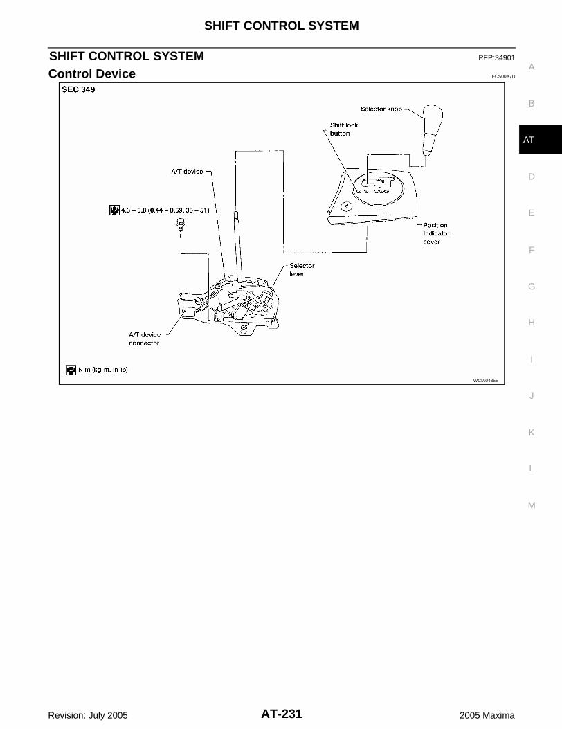
SHIFT CONTROL SYSTEM
AT-231
D
E
F
G
H
I
J
K
L
M
A
B
AT
Revision: July 2005 2005 Maxima
SHIFT CONTROL SYSTEM PFP:34901
Control Device ECS00A7D
WCIA0435E

AT-232
SHIFT CONTROL SYSTEM
Revision: July 2005 2005 Maxima
Control Cable ECS00A7E
BBIA0271E

A/T SHIFT LOCK SYSTEM
AT-233
D
E
F
G
H
I
J
K
L
M
A
B
AT
Revision: July 2005 2005 Maxima
A/T SHIFT LOCK SYSTEM PFP:34950
Description ECS00A7F
The electrical key interlock mechanism also operates as a shift lock:With the key switch turned to ON, the selector lever cannot be shifted from “P” (parking) to any other posi-tion unless the brake pedal is depressed.With the key removed, the selector lever cannot be shifted from “P” to any other position.The key cannot be removed unless the selector lever is placed in “P”.
The shift lock and key interlock mechanisms are controlled by the ON-OFF operation of the shift lock sole-noid and by the operation of the rotator and slider located inside the key cylinder.
Shift Lock System Electrical Parts Location ECS00A7G
BBIA0268E

AT-234
A/T SHIFT LOCK SYSTEM
Revision: July 2005 2005 Maxima
Wiring Diagram — AT — SHIFT ECS00A7H
BCWA0294E

A/T SHIFT LOCK SYSTEM
AT-235
D
E
F
G
H
I
J
K
L
M
A
B
AT
Revision: July 2005 2005 Maxima
Shift Lock Control Unit Reference Values ECS00A7I
SHIFT LOCK HARNESS CONNECTOR TERMINAL LAYOUT
SHIFT LOCK CONTROL UNIT INSPECTION TABLEData are reference values.
NOTE:Make sure that the pointer swings only momentarily because the output time is so short. If the inspection is done with an oscilloscope, itshould be observed that the power source voltage lasts for 3.5 to 10 ms.
LCIA0087E
Terminal No.(Wire color) Item Condition Judgement standard
(+) (-)
1 (Y/R) 8 (B) Power source Always Battery voltage
2 (BR/Y) 8 (B) Detent switch (key)
The position when the key is inserted and the selector lever is set to a position other than the “P” position, or when it is shifted from the “R” to the “P” position
Battery voltage
Except the above Approx. 0V
4 (P/L) 8 (B) Stop lamp switchWhen brake pedal is depressed Battery voltage
When brake pedal is released Approx. 0V
5 (BR) 8 (B)Vehicle speed sig-nal
— —
6 (G) 8 (B) Ignition signalIgnition switch: “ON” Battery voltage
Ignition switch: “OFF” Approx. 0V
7 (R/W) 8 (B) Shift lock solenoid
When the brake pedal is depressed Battery voltage
Ignition switch: “ON” and vehicle speed is less than 8 km/h (5 MPH)
Approx. 0V
8 (B) – Ground Always Approx. 0V
9 (R) 8 (B) Key lock signal
When the selector lever is set to a position other than the “P” position
Battery voltage for approx. 0.1 sec. (Note)
Except the above Approx. 0V
10 (W/G) 8 (B) Key unlock signalWhen the selector lever is set to the“ P” position
Battery voltage for approx. 0.1 sec. (Note)
Except the above Approx. 0V
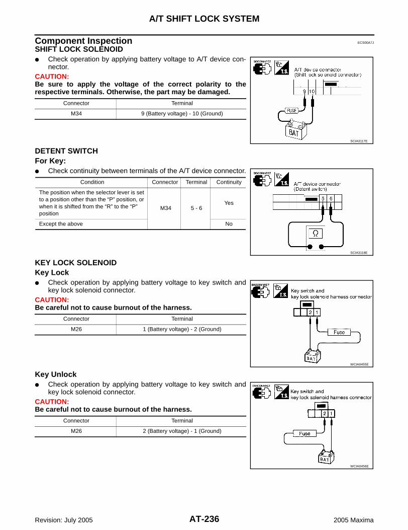
AT-236
A/T SHIFT LOCK SYSTEM
Revision: July 2005 2005 Maxima
Component Inspection ECS00A7J
SHIFT LOCK SOLENOID Check operation by applying battery voltage to A/T device con-
nector.CAUTION:Be sure to apply the voltage of the correct polarity to therespective terminals. Otherwise, the part may be damaged.
DETENT SWITCHFor Key: Check continuity between terminals of the A/T device connector.
KEY LOCK SOLENOIDKey Lock Check operation by applying battery voltage to key switch and
key lock solenoid connector.CAUTION:Be careful not to cause burnout of the harness.
Key Unlock Check operation by applying battery voltage to key switch and
key lock solenoid connector.CAUTION:Be careful not to cause burnout of the harness.
Connector Terminal
M34 9 (Battery voltage) - 10 (Ground)
SCIA3117E
Condition Connector Terminal Continuity
The position when the selector lever is set to a position other than the “P” position, or when it is shifted from the “R” to the “P” position
M34 5 - 6Yes
Except the above No
SCIA3118E
Connector Terminal
M26 1 (Battery voltage) - 2 (Ground)
WCIA0455E
Connector Terminal
M26 2 (Battery voltage) - 1 (Ground)
WCIA0456E

A/T SHIFT LOCK SYSTEM
AT-237
D
E
F
G
H
I
J
K
L
M
A
B
AT
Revision: July 2005 2005 Maxima
KEY SWITCH Check continuity between terminals of the key switch and key
lock solenoid connector.
STOP LAMP SWITCH Check continuity between terminals of the stop lamp switch con-
nector.
Check stop lamp switch after adjusting brake pedal. Refer to BR-6,"Inspection and Adjustment" .
Condition Connector Terminal Continuity
Key insertedM27 3 - 4
Yes
Key removed No
WCIA0457E
Condition Connector Terminal Continuity
When brake pedal is depressedE38 1 - 2
Yes
When brake pedal is released No
PCIA0055E

AT-238
ON-VEHICLE SERVICE
Revision: July 2005 2005 Maxima
ON-VEHICLE SERVICE PFP:00000
Revolution Sensor Replacement ECS00BTV
1. Remove intake air duct. Refer to EM-16, "REMOVAL" .2. Disconnect electrical connector.3. Remove revolution sensor from A/T.4. Reinstall any part removed.
Tighten the revolution sensor bolt to the specified torque.Refer to AT-245, "OVERHAUL" .
NOTE: Apply clean ATF to the revolution sensor O-ring before instal-
lation. Do not reuse seal bolt.
Turbine Revolution Sensor Replacement ECS00BTW
1. Remove battery and bracket. Refer to SC-9, "REMOVAL" .2. Disconnect electrical connector.3. Remove bolt, and turbine revolution sensor from A/T.4. Reinstall any part removed.
Tighten the turbine revolution sensor bolt to the specifiedtorque. Refer to AT-245, "OVERHAUL" .
NOTE: Apply clean ATF to the turbine revolution sensor O-ring before
installation. Do not reuse seal bolt.
Park/Neutral Position (PNP) Switch Adjustment ECS00BTX
1. Remove battery and bracket. Refer to SC-9, "REMOVAL" .2. Remove cable from range lever.3. Set range lever in neutral position.4. Remove range lever and install Tool.
5. Loosen park/neutral position (PNP) switch bolts.6. Adjust PNP switch so that Tool pointer aligns with neutral base
line on PNP switch body.
7. Tighten PNP switch bolts. Refer to AT-245, "OVERHAUL" .8. Reinstall range lever and cable.9. Adjust control cable. Refer to AT-240, "Control Cable Adjust-
ment" .10. Reinstall battery and bracket. Refer to SC-9, "INSTALLATION" .11. Check continuity of PNP switch. Refer to AT-94, "Component
Inspection" .
BBIA0272E
SCIA4137E
Tool number : KV991J0060 (J-45404)
SCIA2800E
BBIA0274E

ON-VEHICLE SERVICE
AT-239
D
E
F
G
H
I
J
K
L
M
A
B
AT
Revision: July 2005 2005 Maxima
ATF Cooler ECS00BTY
REMOVAL1. Drain ATF. Refer to MA-22, "Changing A/T Fluid" .2. Drain engine coolant. Refer to MA-14, "Changing Engine Coolant" .3. Remove hose clamps and hoses from ATF cooler.4. Remove bolt from ATF cooler and remove ATF cooler.
INSTALLATIONInstallation is the reverse order of removal.NOTE: Do not reuse sealing parts.
ATF Cooler Valve ECS00BTZ
Refer to the figure for ATF cooler valve and hoses removal and installation information.
BBIA0275E
1. ATF cooler valve assembly 2. Hose clamp 3. Heater hose
4. Heater pipe 5. Outlet water hose 6. Hose clip
7. ATF cooler assembly 8. Transaxle assembly 9. Control cable bracket
10. Inlet water hose
SCIA2975E

AT-240
ON-VEHICLE SERVICE
Revision: July 2005 2005 Maxima
COMPONENT INSPECTION1. Make sure that ATF cooler valve is fully opened at room temper-
ature.
2. Submerge ATF cooler valve in a water-filled container, and thenheat it up with temperature of over 82°C (180°F) for 10 minutesmore.
3. Make sure that ATF cooler valve is fully closed.
Control Cable Adjustment ECS00BU0
Move selector lever from the P position to the D position. You shouldbe able to feel the detent in each position. If the detent cannot be feltor the pointer indicating the position is improperly aligned, the controlcable needs adjustment.1. Place selector lever in the P position.
CAUTION:Turn wheels more than 1/4 turn and apply the parking brake.
2. Loosen control cable lock nut.3. Using the specified force, push control cable in the direction of
the arrow shown.
4. Tighten control cable lock nut.5. Move selector lever from P to D position. Make sure that selector lever moves smoothly.
Make sure that the starter operates when the selector lever is placed in the N or P position. Make sure that the transmission is locked properly when the selector lever is placed in the P
position.
Dimension “A”: More than 72.0 mm (2.835 in)A: Distance between ATF cooler valve port end face
and valve shaft end face.
SCIA2711J
SCIA2993E
Dimension “A”: Less than 66.5 mm (2.618 in)A: Distance between ATF cooler valve port end face
and valve shaft end face.
SCIA2711J
Specified force : 9.8 N (1.0 kg, 2.2 lb)BBIA0279E
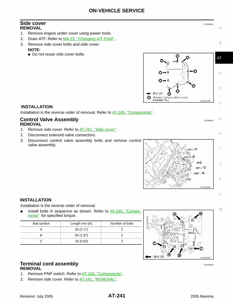
ON-VEHICLE SERVICE
AT-241
D
E
F
G
H
I
J
K
L
M
A
B
AT
Revision: July 2005 2005 Maxima
Side cover ECS00BU1
REMOVAL1. Remove engine under cover using power tools.2. Drain ATF. Refer to MA-22, "Changing A/T Fluid" .3. Remove side cover bolts and side cover.
NOTE: Do not reuse side cover bolts
INSTALLATIONInstallation is the reverse order of removal. Refer to AT-245, "Components" .
Control Valve Assembly ECS00BU2
REMOVAL1. Remove side cover. Refer to AT-241, "Side cover" .2. Disconnect solenoid valve connectors.3. Disconnect control valve assembly bolts and remove control
valve assembly.
INSTALLATIONInstallation is the reverse order of removal. Install bolts in sequence as shown. Refer to AT-245, "Compo-
nents" for specified torque.
Terminal cord assembly ECS00BU3
REMOVAL1. Remove PNP switch. Refer to AT-245, "Components" .2. Remove side cover. Refer to AT-241, "REMOVAL" .
SCIA4144E
SCIA4151E
Bolt symbol Length mm (in) Number of bolts
A 55 (2.17) 2
B 50 (1.97) 2
C 16 (0.63) 2
SCIA4152E

AT-242
ON-VEHICLE SERVICE
Revision: July 2005 2005 Maxima
3. Disconnect solenoid valve connectors.4. Remove terminal cord assembly.
INSTALLATIONInstallation is in the reverse order of removal.
WCIA0238E

TRANSAXLE ASSEMBLY
AT-243
D
E
F
G
H
I
J
K
L
M
A
B
AT
Revision: July 2005 2005 Maxima
TRANSAXLE ASSEMBLY PFP:32020
Removal and Installation ECS00BUS
REMOVALCAUTION: When removing the transaxle assembly from engine, first remove the crankshaft position sensor
from the assembly. Be careful not to damage sensor edge.1. Drain engine coolant. Refer to MA-14, "Changing Engine Coolant" .2. Remove battery and bracket. Refer to SC-9, "REMOVAL" .3. Remove air cleaner assembly. Refer to EM-16, "Removal and Installation" .4. Disconnect terminal cord assembly harness connector and park/neutral position (PNP) switch harness
connectors.5. Disconnect harness connectors of revolution sensor, ground, mass air flow sensor, and turbine revolution
sensor.6. Remove ATF cooler valve assembly bracket bolts.7. Disconnect ATF cooler hose clips.8. Disconnect ATF cooler hoses from ATF cooler valve assembly.9. Disconnect control cable at transaxle side.10. Drain ATF. Refer to MA-22, "Changing A/T Fluid" .11. Remove engine undercover.12. Remove upper transaxle to engine bolts.13. Support engine. Refer to EM-117, "ENGINE ASSEMBLY" .14. Remove drive shafts. Refer to FAX-11, "Removal and Installation" .15. Remove crankshaft position sensor from transaxle.16. Support transaxle with a jack.17. Remove starter motor from transaxle. Refer to SC-17, "Removal and Installation" .18. Remove front suspension member. Refer to FSU-15, "Removal and Installation" .19. Remove rear cover plate and bolts securing torque converter to
drive plate. Rotate crankshaft for access to securing bolts.
20. Remove lower transaxle to engine bolts.21. Lower transaxle while supporting it with a jack.22. If replacing the transaxle as a unit, remove the LH transaxle
mount from the transaxle case.
INSPECTION AFTER REMOVAL ECS00BUT
Drive plate runoutCAUTION:Do not allow any magnetic materials to contact the ringgear teeth.
If this runout is out of allowance, replace drive plate and ringgear.
BBIA0277E
Maximum allowable runout:Refer to EM-148, "DRIVE PLATE RUNOUT (A/T)" .
SAT977H

AT-244
TRANSAXLE ASSEMBLY
Revision: July 2005 2005 Maxima
INSTALLATIONCAUTION: When replacing an engine or transmission you must make sure the dowels are installed correctly
during re-assembly. Improper alignment caused by missing dowels may cause vibration, oil leaks or breakage of drive
train components.1. When connecting torque converter to transaxle, measure dis-
tance “A” to be certain that they are correctly assembled.
2. Install converter bolts to drive plate.
NOTE:With converter installed, rotate crankshaft several turns to checkthat transaxle rotates freely without binding.
3. Tighten bolts securing transaxle.
4. Tighten LH mounting bracket bolts to the specified torque. Referto EM-117, "Removal and Installation" .
5. Tighten front suspension member bolts to the specified torque.Refer to FSU-15, "Removal and Installation" .
6. Tighten rear plate cover bolts to the specified torque. Refer to EM-31, "Removal and Installation" .7. Installation of the remaining components is in the reverse order of removal.
Check fluid level in transaxle. Move selector lever through all positions to be sure that tran-
saxle operates correctly. With parking brake applied, rotate engine at idling. Move
selector lever through N to D and to R position. A slight shockshould be felt by hand gripping selector each time transaxle isshifted.
When replacing the A/T assembly, initialize TCM. Refer to AT-8, "Precautions for A/T Assembly or TCM Replacement" .
Perform road test. Refer to AT-57, "ROAD TEST" .
Distance “A” : 14.0 mm (0.551 in) or more
SAT044A
Converter bolt : 49 - 58 N·m (5.0 - 5.9 kg-m, 37 - 42 ft-lb)
WCIA0070E
Bolt No.Tightening torqueN·m (kg-m, ft-lb) mm (in)
1 70 - 79 (7.2 - 8.0, 52 - 58) 55 (2.17)
2 41.2 - 52.0 (4.2 - 5.3, 31 - 38) 40 (1.57)
3 70 - 79 (7.2 - 8.0, 52 - 58) 55 (2.17)
SCIA3017E
SAT638A

OVERHAUL
AT-245
D
E
F
G
H
I
J
K
L
M
A
B
AT
Revision: July 2005 2005 Maxima
OVERHAUL PFP:00000
Components ECS00BU6
WCIA0334E

AT-246
OVERHAUL
Revision: July 2005 2005 Maxima
1. Adjust shim 2. O-ring 3. Differential gear assembly
4. O-ring 5. Tapered roller bearing 6. Tapered roller bearing
7. Outer race 8. O-ring 9. Compression spring
10. U/D brake piston assembly 11. U/D brake damper assembly 12. Snap ring
13. U/D brake band assembly 14. U/D clutch assembly 15. U/D gear assembly
16. Thrust needle roller bearing 17. Thrust bearing race 18. Seal ring
19. Transaxle case 20. B5 brake cushion plate 21. B5 brake disc
22. Snap ring 23. U/D RR planetary ring gear sub assembly 24. Thrust bearing race
25. U/D RR planetary carrier assembly 26. Thrust needle roller bearing 27. Thrust bearing race
28. B5 brake flange 29. B5 brake plate 30. O-ring
31. Snap ring 32. Return spring 33. B5 brake piston
34. Transaxle case cover

OVERHAUL
AT-247
D
E
F
G
H
I
J
K
L
M
A
B
AT
Revision: July 2005 2005 Maxima
1. Snap ring 2. 2nd brake plate 3. Return spring
4. O-ring 5. Oil pump assembly 6. Oil seal
7. 2nd brake piston 8. 2nd brake sleeve 9. Snap ring
WCIA0385E

AT-248
OVERHAUL
Revision: July 2005 2005 Maxima
10. 2nd brake disc 11. 2nd brake flange 12. One-way clutch No.1
13. 2nd coast brake hub 14. Snap ring 15. 2nd coast brake plate
16. Snap ring 17. O-ring 18. 2nd coast brake piston
19. Return spring 20. 2nd coast brake disc 21. 2nd coast brake flange
22. Thrust washer 23. Thrust washer 24. Return spring
25. 1st and reverse brake piston 26. Thrust bearing race 27. Counter drive gear sub assembly
28. One-way clutch outer race sub assem-bly
29. Thrust washer 30. Snap ring
31. Thrust bearing 32. O-ring 33. Snap ring
34. Planetary gear assembly 35. FR planetary ring gear assembly 36. Snap ring
37. 1st and reverse brake disc 38. 1st and reverse brake flange 39. 1st and reverse brake plate
40.
1st and reverse brake flange 41. One-way clutch No.2 42. Thrust bearing
43. Thrust bearing race 44. Thrust needle roller bearing 45. Seal ring
46. Forward and direct clutch assembly 47. Planetary sun gear sub assembly 48. Thrust bearing race
49. Thrust needle roller bearing 50. RR planetary ring gear assembly 51. Thrust needle roller bearing
52. Thrust bearing race

OVERHAUL
AT-249
D
E
F
G
H
I
J
K
L
M
A
B
AT
Revision: July 2005 2005 Maxima
1. Transaxle case cover 2. Seal ring 3. Forward clutch accumulator piston
4. Compression spring 5. Accumulator cover 6. O-ring
7. Seal ring 8. Range lever 9. Washer plate
SCIA4096E

AT-250
OVERHAUL
Revision: July 2005 2005 Maxima
10. PNP switch 11. Lock washer 12. Parking lock pawl
13. Torsion spring No.1 14. Parking lock pawl shaft 15. Spring guide sleeve
16. Torsion spring No.2 17. Parking lockpin sub assembly 18. U/D brake apply tube sub assembly
19. Tube clamp 20. Oil reservoir plate 21. Oil cleaner magnet
22. Tube clamp 23. Differential gear lube apply tube 24. Seal ring
25. Thrust roller bearing 26. Straight screw plug 27. O-ring
28. Straight screw plug 29. Differential side oil seal 30. Torque converter
31. Transaxle housing 32. O-ring 33. O-ring
34. Spring washer 35. Hexagon bolt 36. Washer
37. ATF cooler assembly 38. gasket 39. Drain plug
40. Breather hose 41. O-ring 42. A/T fluid charging pipe
43. A/T fluid level gauge 44. Manual valve lever sub assembly 45. Parking lock rod sub assembly
46. Control valve assembly 47. Suction cover gasket 48. Suction cover
49. Side cover 50. Seal bolt 51. Governor apply gasket
52. Sensor clamp 53. Transmission wire 54. Transaxle lube apply tube
55. Tube clamp 56. Tube clamp 57. U/D clutch apply tube sub assembly
58. Bearing race 59. Seal ring 60. Seal bolt
61. Turbine revolution sensor 62. Differential side oil seal 63. Manual valve oil seal
64. O-ring 65. Anchor bolt 66. Revolution sensor
67. Seal bolt 68. Governor apply gasket 69. Transaxle case
70. Oil reserver plate 71. Oil strainer sub assembly 72. Manual detent spring sub assembly
73. Parking lock pawl bracket 74. Governor apply gasket

OVERHAUL
AT-251
D
E
F
G
H
I
J
K
L
M
A
B
AT
Revision: July 2005 2005 Maxima
Locations of Needle Bearings, Bearing Races and Thrust Washers ECS00BU7
SCIA4478E
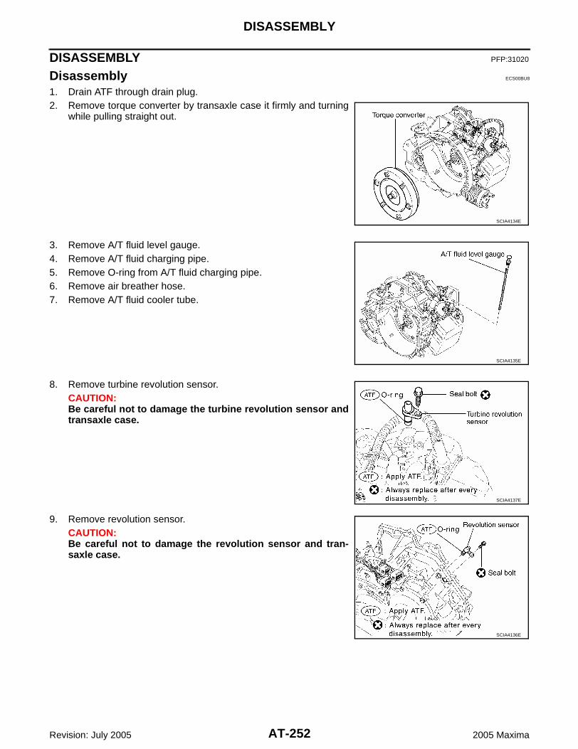
AT-252
DISASSEMBLY
Revision: July 2005 2005 Maxima
DISASSEMBLY PFP:31020
Disassembly ECS00BU8
1. Drain ATF through drain plug.2. Remove torque converter by transaxle case it firmly and turning
while pulling straight out.
3. Remove A/T fluid level gauge.4. Remove A/T fluid charging pipe.5. Remove O-ring from A/T fluid charging pipe.6. Remove air breather hose.7. Remove A/T fluid cooler tube.
8. Remove turbine revolution sensor.CAUTION:Be careful not to damage the turbine revolution sensor andtransaxle case.
9. Remove revolution sensor.CAUTION:Be careful not to damage the revolution sensor and tran-saxle case.
SCIA4134E
SCIA4135E
SCIA4137E
SCIA4136E

DISASSEMBLY
AT-253
D
E
F
G
H
I
J
K
L
M
A
B
AT
Revision: July 2005 2005 Maxima
10. Remove nut and range lever.
11. Using a flat-bladed screwdriver, pry off the lock washer.
12. Loosen nut and remove lock washer.13. Remove washer plate.
14. Remove PNP switch from transaxle case.
SCIA4138E
SCIA4139E
SCIA4140E
Bolt symbol Length mm (in) Number of bolts
A 20 (0.79) 1
B 33 (1.30) 1
SCIA4141E

AT-254
DISASSEMBLY
Revision: July 2005 2005 Maxima
15. Remove hexagon bolt.16. Remove ATF cooler assembly, washer and spring washer.17. Remove O-rings from the ATF cooler assembly.
NOTE:Do not reuse spring washer or O-rings.
18. Remove side cover.CAUTION:Be careful not to damage side cover and transaxle case.
NOTE:Do not reuse seal bolts
SCIA4142E
SCIA4143E
SCIA4144E

DISASSEMBLY
AT-255
D
E
F
G
H
I
J
K
L
M
A
B
AT
Revision: July 2005 2005 Maxima
19. Disconnect solenoid connectors.CAUTION:Be careful not to damage connector.
20. Remove sensor clamp bolt.
21. Remove sensor clamp and A/T fluid temperature sensor.CAUTION:Be careful not to damage A/T fluid temperature sensor.
22. Remove suction cover bolts.
SCIA4146E
SCIA4148E
SCIA4147E
SCIA4150E

AT-256
DISASSEMBLY
Revision: July 2005 2005 Maxima
23. Remove suction cover and suction cover gasket.
24. Remove control valve assembly bolts from transaxle case.
25. While holding control valve assembly, disconnect parking lockrod sub assembly from manual valve lever sub assembly andremove control valve assembly.NOTE:Shift position is “N”.
26. Remove governor apply gaskets.
SCIA4149E
Bolt symbol Length mm (in) Number of bolts
A 55 (2.17) 2
B 50 (1.97) 2
C 16 (0.63) 2
SCIA4152E
SCIA4153E
SCIA4154E

DISASSEMBLY
AT-257
D
E
F
G
H
I
J
K
L
M
A
B
AT
Revision: July 2005 2005 Maxima
27. Remove terminal cord assembly.CAUTION:Be careful not to damage solenoid connectors and A/T fluidtemperature sensor.
28. Remove oil pump assembly bolts from transaxle case.
29. Remove oil pump assembly using Tool.
SCIA4155E
SCIA4156E
SCIA4157E
Tool number ST33290001 (J-34286)
SCIA5359E

AT-258
DISASSEMBLY
Revision: July 2005 2005 Maxima
30. Remove oil seal from oil pump assembly using suitable tool.CAUTION:Be careful not to scratch oil pump assembly.
31. Remove one-way clutch outer race sub assembly.32. Remove thrust washer.
33. Remove transaxle housing bolts from transaxle case.
*:Torx bolt
34. Remove transaxle housing with a soft hammer.
SCIA4396E
SCIA4159E
Bolt symbol Length mm (in) Number of bolts
A 30 (1.18) 13
B 35 (1.38) 2
C 45 (1.77) 1
D* — 1
SCIA4160E
SCIA5495E
SCIA4162E
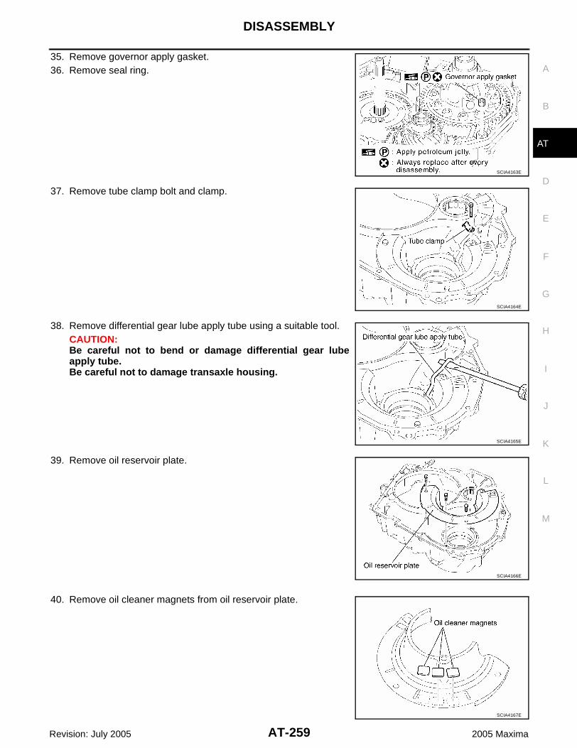
DISASSEMBLY
AT-259
D
E
F
G
H
I
J
K
L
M
A
B
AT
Revision: July 2005 2005 Maxima
35. Remove governor apply gasket.36. Remove seal ring.
37. Remove tube clamp bolt and clamp.
38. Remove differential gear lube apply tube using a suitable tool.CAUTION:Be careful not to bend or damage differential gear lubeapply tube.Be careful not to damage transaxle housing.
39. Remove oil reservoir plate.
40. Remove oil cleaner magnets from oil reservoir plate.
SCIA4163E
SCIA4164E
SCIA4165E
SCIA4166E
SCIA4167E

AT-260
DISASSEMBLY
Revision: July 2005 2005 Maxima
41. Remove differential gear assembly.
42. Remove oil strainer sub assembly.
43. Remove oil reservoir plate.
44. Remove tube clamp.
45. Remove U/D brake apply tube sub assembly using suitable tool.CAUTION:Be careful not to bend or damage U/D brake apply tube subassembly.Be careful not to damage transaxle case.
SCIA4168E
SCIA4169E
SCIA4170E
SCIA4171E
SCIA4172E

DISASSEMBLY
AT-261
D
E
F
G
H
I
J
K
L
M
A
B
AT
Revision: July 2005 2005 Maxima
46. Disconnect manual detent spring sub assembly from manualvalve lever sub assembly using a flat-bladed screwdriver or suit-able tool.
47. Remove manual valve lever sub assembly from parking lock rodsub assembly.
48. Remove parking lock rod sub assembly.
49. Remove bolts for manual detent spring sub assembly.
50. Remove manual detent spring sub assembly.
SCIA4174E
SCIA4175E
SCIA4176E
Bolt symbol Length mm (in) Number of bolts
A 16.7 (0.657) 1
B 14.0 (0.551) 1
SCIA4177E
SCIA4178E

AT-262
DISASSEMBLY
Revision: July 2005 2005 Maxima
51. Remove parking lock pawl shaft and torsion spring No.1.
52. Remove parking lock pawl bracket and parking lock pawl.
53. Remove parking lockpin sub assembly.
54. Remove spring guide sleeve and torsion spring No.2.
55. Remove manual valve oil seal using a flat-bladed screwdriver.CAUTION:Be careful not to damage transaxle case.
SCIA4179E
WCIA0341E
SCIA4181E
SCIA4182E
SCIA4183E

DISASSEMBLY
AT-263
D
E
F
G
H
I
J
K
L
M
A
B
AT
Revision: July 2005 2005 Maxima
56. Remove thrust needle roller bearing and thrust bearing racefrom U/D gear assembly.
57. Remove U/D gear assembly.58. Remove seal rings from U/D gear assembly.
59. Remove U/D clutch assembly.
60. Remove anchor bolt.
61. Remove U/D brake band assembly.CAUTION:Be careful not to damage transaxle case.
WCIA0338E
SCIA4185E
SCIA4186E
SCIA4193E
SCIA4187E

AT-264
DISASSEMBLY
Revision: July 2005 2005 Maxima
62. Remove U/D RR planetary carrier assembly and thrust bearingraces.
63. Remove U/D RR planetary ring gear sub assembly.64. Remove thrust needle roller bearing adjusting shim and thrust
bearing race from U/D RR planetary ring gear sub assembly.
65. Remove snap ring using a snap ring pliers
66. Remove U/D brake damper assembly.67. Remove O-rings from U/D brake damper assembly.
68. Remove U/D brake piston assembly and compression spring.69. Remove O-ring from U/D brake piston assembly.
SCIA5505E
WCIA0339E
SCIA4190E
SCIA4191E
SCIA4192E

DISASSEMBLY
AT-265
D
E
F
G
H
I
J
K
L
M
A
B
AT
Revision: July 2005 2005 Maxima
70. Remove transaxle case cover bolts from transaxle case.
*:Stud bolt
71. Tap transaxle case cover with a soft hammer.CAUTION:Be careful not to damage transaxle case cover.
72. Remove transaxle case cover.
73. Remove governor apply gaskets from transaxle case.NOTE:Do not reuse gaskets
Bolt symbol Length mm (in) Number of bolts
A 30 (1.18) 8
B 45 (1.77) 2
C 48 (1.89) 2
D* — 1
SCIA4194E
SCIA4195E
SCIA4196E
SCIA4197E
SCIA4198E

AT-266
DISASSEMBLY
Revision: July 2005 2005 Maxima
74. Remove tube clamp bolt.
75. Remove transaxle lube apply tube, using a flat-bladed screw-driver.CAUTION:Be careful not to bend or damage transaxle lube apply tube.Be careful not to damage transaxle case.
76. Remove forward and direct clutch assembly.77. Remove thrust bearing race, thrust needle roller bearing and
seal ring from forward and direct clutch assembly.NOTE:Do not reuse seal ring.
78. Remove planetary sun gear sub assembly and thrust needleroller bearings.
79. Measure the inner diameter of planetary sun gear sub assemblybushing, using suitable bore gauge.CAUTION:Measure at different places and take an average. If it isgreater than the maximum, replace it with a new planetarysun gear sub assembly.
SCIA4199E
SCIA4200E
WCIA0384E
SCIA5499E
Standard :22.200 - 22.226mm (0.8740 - 0.8750in)Allowable limit :22.276 (0.8770in)
SCIA4255E

DISASSEMBLY
AT-267
D
E
F
G
H
I
J
K
L
M
A
B
AT
Revision: July 2005 2005 Maxima
80. Remove RR planetary ring gear assembly.81. Remove thrust needle roller bearing and thrust bearing race
from RR planetary ring gear assembly.
82. Remove planetary gear assembly.83. Remove thrust bearing race from planetary gear assembly.
84. Measure the inner diameter of planetary gear assembly bush-ing, using suitable bore gauge.CAUTION:Measure at different places and take an average. If it isgreater than the maximum, replace it with a new planetarygear assembly.
85. Remove thrust bearing.
SCIA4256E
SCIA4203E
SCIA4204E
Standard :30.056 - 30.082mm (1.1833 - 1.1843in)Allowable limit :30.132 (1.1863in)
SCIA4254E
SCIA4205E
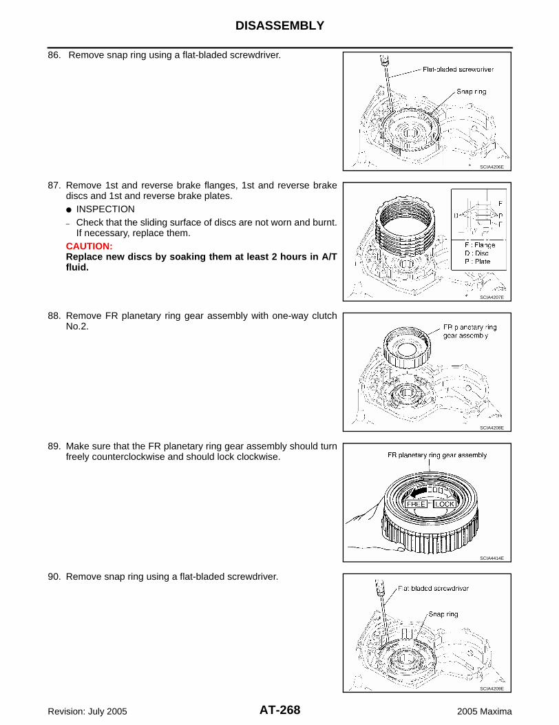
AT-268
DISASSEMBLY
Revision: July 2005 2005 Maxima
86. Remove snap ring using a flat-bladed screwdriver.
87. Remove 1st and reverse brake flanges, 1st and reverse brakediscs and 1st and reverse brake plates. INSPECTION– Check that the sliding surface of discs are not worn and burnt.
If necessary, replace them.CAUTION:Replace new discs by soaking them at least 2 hours in A/Tfluid.
88. Remove FR planetary ring gear assembly with one-way clutchNo.2.
89. Make sure that the FR planetary ring gear assembly should turnfreely counterclockwise and should lock clockwise.
90. Remove snap ring using a flat-bladed screwdriver.
SCIA4206E
SCIA4207E
SCIA4208E
SCIA4414E
SCIA4209E

DISASSEMBLY
AT-269
D
E
F
G
H
I
J
K
L
M
A
B
AT
Revision: July 2005 2005 Maxima
91. Remove return spring.
92. While pushing the piston by hand, apply compressed air (4Kg/cm2 ) into the oil passage of transaxle case as shown in the fig-ure and remove 1st and reverse brake piston.
93. Remove O-rings from 1st and reverse brake piston.NOTE:Do not reuse O-Rings.
94. Remove thrust bearing and thrust bearing race from counterdrive gear sub assembly.
95. Remove snap ring using a suitable snap ring pliers.
SCIA4210E
SCIA4211E
SCIA4212E
SCIA4213E
SCIA4214E

AT-270
DISASSEMBLY
Revision: July 2005 2005 Maxima
96. Remove counter drive gear sub assembly.
97. Remove differential side oil seal from transaxle case and tran-saxle housing using suitable tool.CAUTION:Be careful not to scratch transaxle case and transaxlehousing.
NOTE:Do not reuse oil seals
98. Remove outer race and adjust shim from transaxle case, usingTool
SCIA4215E
SCIA4216E
SCIA4217E
Tool number : ST30612000 (J-25745-2)
SCIA5360E

DISASSEMBLY
AT-271
D
E
F
G
H
I
J
K
L
M
A
B
AT
Revision: July 2005 2005 Maxima
99. Remove thrust roller bearing from transaxle housing, using Tool.
Tool number : ST333290001 (J-34286)
SCIA5361E

AT-272
REPAIR FOR COMPONENT PARTS
Revision: July 2005 2005 Maxima
REPAIR FOR COMPONENT PARTS PFP:00000
Oil Pump, 2nd Coast Brake & 2nd Brake ECS00BUU
COMPONENTS
DISASSEMBLY1. Remove oil seal from oil pump assembly, using suitable tool.
CAUTION:Be careful not to scratch oil pump assembly.NOTE:Do not reuse old seal.
1. Return spring 2. Snap ring 3. O-ring
4. Oil seal 5. Oil pump assembly 6. 2nd brake piston
7. 2nd brake sleeve 8. O-ring 9. 2nd brake flange
10. 2nd brake plate 11. 2nd brake disc 12. Snap ring
13. 2nd coast brake piston 14. Return spring 15. Thrust washer
16. 2nd coast brake flange 17. 2nd coast brake plate 18. Snap ring
19. 2nd coast brake disc 20. Snap ring
SCIA4384E
SCIA4396E

REPAIR FOR COMPONENT PARTS
AT-273
D
E
F
G
H
I
J
K
L
M
A
B
AT
Revision: July 2005 2005 Maxima
2. Remove thrust washer from oil pump assembly.
3. Remove snap ring, using a flat-bladed screwdriver.
4. Remove 2nd coast brake flange, 2nd coast brake disc and 2ndcoast brake plate.
5. Compress return spring with a press, using Tool.
6. Remove snap ring, using suitable snap ring pliers.
7. Remove return spring.
SCIA4218E
SCIA4219E
SCIA4220E
Tool number : KV31102400 (J-34285 and J-34285-87)
SCIA5362E
SCIA4222E

AT-274
REPAIR FOR COMPONENT PARTS
Revision: July 2005 2005 Maxima
8. While pushing the 2nd coast brake piston by hand, apply com-pressed air (4kg/cm2 ) into the oil passage as shown andremove 2nd coast brake piston.CAUTION:Be careful not to damage the O-ring and 2nd coast brakepiston.
9. Remove O-rings from 2nd coast brake piston.NOTE:Do not reuse O-rings.
10. Remove snap ring, using suitable tool.
11. Remove 2nd brake flange, 2nd brake discs and 2nd brakeplates.
12. Remove return spring.
13. Remove snap ring, using suitable tool.CAUTION:Be careful not to damage oil pump assembly and 2nd brakepiston.
SCIA4223E
SCIA4224E
SCIA4225E
SCIA4226E
SCIA4227E

REPAIR FOR COMPONENT PARTS
AT-275
D
E
F
G
H
I
J
K
L
M
A
B
AT
Revision: July 2005 2005 Maxima
14. While pushing the 2nd brake piston by hand, apply compressedair (4kg/cm2 ) into the oil passage as shown and remove 2ndbrake piston (With 2nd brake sleeve).CAUTION:Be careful not to damage 2nd brake piston and 2nd brakesleeve.
15. Remove O-rings from 2nd brake piston and 2nd brake sleeve.NOTE:Do no reuse O-rings.
INSPECTION Check that the sliding surface of disc and plate is not worn or burnt. If the disc or plate is worn or burnt,
replace itNOTE:Replace new clutch discs by soaking them at least 2 hours in ATF.
ASSEMBLY1. Install new O-rings in 2nd brake sleeve and 2nd brake piston.
NOTE: Do not reuse O-ring. Apply ATF to O-ring.
2. Coat the inner surfaces of oil pump assembly with ATF.3. Press 2nd brake piston and 2nd brake sleeve into oil pump
assembly.
4. Install snap ring, using suitable tool.CAUTION:Be careful not to damage oil pump assembly.
5. Place return spring on 2nd brake piston with the spring side up.
SCIA4228E
SCIA4229E
SCIA4227E
SCIA4226E

AT-276
REPAIR FOR COMPONENT PARTS
Revision: July 2005 2005 Maxima
6. Install 2nd brake flange, 2nd brake discs and 2nd brake plates.
7. Install snap ring, using suitable tool.
8. Install new O-rings in 2nd coast brake piston.NOTE: Do not reuse O-rings. Apply ATF to O-rings.
9. Coat the inner surfaces of oil pump assembly with ATF.10. Press 2nd coast brake piston into oil pump assembly.
11. Install return spring.
12. Compress return spring, using Tool.
13. Install snap ring, using suitable snap ring pliers.
SCIA4225E
SCIA4224E
SCIA4230E
SCIA4222E
Tool number : KV31102400 (J-34285 and J-34285-87)
SCIA5362E

REPAIR FOR COMPONENT PARTS
AT-277
D
E
F
G
H
I
J
K
L
M
A
B
AT
Revision: July 2005 2005 Maxima
14. Install 2nd coast brake flange, 2nd coast brake disc and 2ndcoast brake plate.
15. Compress return spring with a press, using Tool.
16. Install snap ring, using suitable tool.
17. Set a dial indicator as shown.
18. When applying compressed air (4Kg/cm2 ) into the oil passageas shown, measure 2nd brake piston stroke and check 2ndbrake piston moves smoothly.
If 2nd brake piston stroke is out standards, select anotherflange. Refer to AT-314, "2ND BRAKE" .
19. Set a dial indicator as shown.
20. When applying compressed air (4Kg/cm2 ) into the oil passageas shown, measure 2nd coast brake piston stroke and check2nd coast brake piston moves smoothly.
21. Install thrust washer facing the flat surface up.NOTE:Apply petroleum jelly to thrust washer.
SCIA4220E
Tool number : KV31102400 (J-34285 and J-34285-87)
SCIA5363E
Piston stroke :1.10 - 1.50mm (0.0433 - 0.0591in)
SCIA5501E
Piston stroke :0.76 - 1.44mm (0.0299 - 0.0567in)
SCIA4233E
SCIA4218E

AT-278
REPAIR FOR COMPONENT PARTS
Revision: July 2005 2005 Maxima
22. Install new oil seal into oil pump assembly until it is flush with theoil pump face, using Tool.
NOTE: Do not reuse oil seal. Apply ATF to oil seal.
One-Way Clutch Outer Race Sub Assembly & 2nd Coast Brake Hub & One-Way Clutch No.1 ECS00BUV
COMPONENTS
DISASSEMBLY1. Remove thrust washer from one-way clutch outer race sub
assembly.
Tool number : ST30720000 (J-25405)
SCIA5364E
1. Thrust washer 2. One-way clutch outer race sub assembly 3. One-way clutch No.1
4. Thrust washer 5. 2nd coast brake hub
SCIA4234E
SCIA4235E

REPAIR FOR COMPONENT PARTS
AT-279
D
E
F
G
H
I
J
K
L
M
A
B
AT
Revision: July 2005 2005 Maxima
2. Remove 2nd coast brake hub from one-way clutch outer racesub assembly.
3. Remove thrust washer from 2nd coast brake hub.
4. Remove one-way clutch No.1 from one-way clutch outer racesub assembly.
ASSEMBLY1. Install one-way clutch No.1 into the one-way clutch outer race
sub assembly.CAUTION:Do not mistake the direction of one-way clutch No.1.
2. Install thrust washer into 2nd coast brake hub.NOTE: Coat the thrust washer with grease. Align the tab of the washer with the hollow of the 2nd coast
brake hub.3. Install 2nd coast brake hub into one-way clutch outer race sub
assembly.NOTE:While turning the 2nd coast brake hub, slide it into one-wayclutch outer race sub assembly.
SCIA4236E
SCIA4237E
SCIA4238E
SCIA4236E

AT-280
REPAIR FOR COMPONENT PARTS
Revision: July 2005 2005 Maxima
4. Coat the thrust washer with petroleum jelly. Align the tab of thewasher with the hollow of the one-way clutch outer race subassembly.NOTE:Apply petroleum jelly to thrust washer.
INSPECTION Hold one-way clutch outer race sub assembly, and check that
2nd coast brake hub should turn freely clockwise and shouldlock counterclockwise.
Transaxle Case Cover & B5 Brake ECS00BUW
COMPONENTS
SCIA4235E
SCIA4239E
SCIA5441E

REPAIR FOR COMPONENT PARTS
AT-281
D
E
F
G
H
I
J
K
L
M
A
B
AT
Revision: July 2005 2005 Maxima
DISASSEMBLY1. Remove tube clamps.
2. Remove U/D clutch apply tube sub assembly, using suitabletool.CAUTION:Be careful not to damage the U/D clutch apply tube subassembly and transaxle case cover.
3. Remove bearing race and seal rings from transaxle case cover.
4. Remove accumulator cover, compression spring and forwardclutch accumulator piston.
5. Remove O-ring from the accumulator cover.NOTE:Do not reuse O-rings.
6. Remove seal ring from the forward clutch accumulator piston.NOTE:Do not reuse seal ring.
1. Transaxle case cover 2. Seal ring 3. O-ring
4. Return spring 5. Snap ring 6. B5 brake piston
7. Seal ring 8. Bearing race 9. U/D clutch apply tube sub assembly
10. Tube clamp 11. Forward clutch accumulator piston 12. Compression spring
13. Accumulator cover 14. O-ring 15. Seal ring
16. B5 brake cushion plate 17. B5 brake plate 18. B5 brake flange
19. Snap ring 20. B5 brake disc
SCIA5502E
SCIA4241E
WCIA0386E
SCIA4243E

AT-282
REPAIR FOR COMPONENT PARTS
Revision: July 2005 2005 Maxima
7. Remove snap ring, using suitable flat blade screwdriver.
8. Remove B5 brake flange, B5 brake discs, B5 brake plates andB5 brake cushion plate.
9. Compress return spring, using Tool.
CAUTION:Do not press return spring too much to avoid deformation.
10. Remove snap ring, using suitable tool.
11. Remove return spring.
12. While pushing B5 brake piston by hand, apply compressed air(4Kg/cm2 ) into the oil passage as shown and remove B5 brakepiston.
SCIA4244E
SCIA4245E
Tool number : KV31102400 (J-34285 and J-34285-87)
SCIA5365E
SCIA4247E
SCIA4248E

REPAIR FOR COMPONENT PARTS
AT-283
D
E
F
G
H
I
J
K
L
M
A
B
AT
Revision: July 2005 2005 Maxima
13. Remove O-rings from B5 brake piston.NOTE:Do not reuse O-rings.
14. Remove seal ring from transaxle case cover.NOTE:Do not reuse seal ring.
INSPECTION Check that the sliding surface of disc and plate is not worn or burnt. If the disc or plate is worn or burnt,
replace itNOTE:Replace new clutch discs by soaking them at least 2 hours in ATF.
ASSEMBLY1. Install new seal ring in transaxle case cover.
NOTE: Do not reuse seal ring. Apply ATF to seal ring.
2. Install new O-rings in B5 brake piston.NOTE: Do not reuse O-rings. Apply ATF to O-rings.
3. Coat the inner surface of transaxle case cover with ATF.4. Press B5 brake piston into the transaxle case cover.
5. Place return spring on B5 brake piston.
6. Compress return spring with a press, using Tool.
CAUTION:Do not press return spring too much to avoid deformation.
7. Install snap ring, using suitable tool.
SCIA4249E
SCIA4249E
SCIA4247E
Tool number : KV31102400 (J-34285 and J-34285-87)
SCIA5365E

AT-284
REPAIR FOR COMPONENT PARTS
Revision: July 2005 2005 Maxima
8. Install B5 brake cushion plate.CAUTION:Be sure direction of B5 brake cushion plate.
9. Install B5 brake flange, B5 brake plates and B5 brake discs asshown.
10. Install snap ring, using suitable tool or flat-bladed screwdriver.
11. Install new O-ring in accumulator cover.NOTE: Do not reuse O-ring. Apply ATF to O-ring.
12. Install new seal ring in forward clutch accumulator piston.NOTE: Do not reuse seal ring. Apply ATF to seal ring.
13. Install forward clutch accumulator piston, compression springand accumulator cover in transaxle case cover.
14. Tighten accumulator cover torx bolts to specified torque. Referto AT-280, "COMPONENTS" .
15. Install new seal rings and bearing race in transaxle case cover.NOTE: Do not reuse seal ring. Apply ATF to O-ring. Refer to ASSEMBLY to select proper bearing race.
SCIA4245E
SCIA4244E
SCIA4243E
WCIA0386E

REPAIR FOR COMPONENT PARTS
AT-285
D
E
F
G
H
I
J
K
L
M
A
B
AT
Revision: July 2005 2005 Maxima
16. Install the U/D clutch apply tube sub assembly, using suitablesoft hammer.
17. Tighten tube clamp bolts to specified torque. Refer to AT-280,"COMPONENTS" .
18. Set a dial indicator as shown.
19. When applying compressed air (4Kg/cm2 ) into the oil passageas shown, measure the B5 brake piston stroke and check the B5brake piston moves smoothly.
If the B5 brake piston stroke is out standards, select anotherflange. Refer to AT-315, "B5 BRAKE" .
Differential Gear Assembly ECS00BUX
COMPONENTS
SCIA4252E
SCIA5502E
Piston stroke :2.34 - 2.70mm (0.0921 - 0.1063in)
SCIA5503E
SCIA4407E

AT-286
REPAIR FOR COMPONENT PARTS
Revision: July 2005 2005 Maxima
DISASSEMBLY1. Remove O-rings from differential gear assembly.
NOTE:Do not reuse O-rings.
2. Remove tapered roller bearings, using suitable puller and Tool.
NOTE:Do not reuse tapered roller bearings.
1. O-ring 2. Tapered roller bearing 3. Differential gear assembly
4. Tapered roller bearing 5. O-ring
SCIA4408E
Tool number : ST33081000 (J-8107-2)
SCIA5366E

REPAIR FOR COMPONENT PARTS
AT-287
D
E
F
G
H
I
J
K
L
M
A
B
AT
Revision: July 2005 2005 Maxima
ASSEMBLY1. Install new tapered roller bearings in differential gear assembly,
using Tool.
NOTE:Do not reuse tapered roller bearings.
2. Install new O-rings in differential gear assembly.NOTE: Do not reuse O-rings. Apply ATF to O-rings.
Tool number : KV38100500 ( — ): ST33720000 (J-25405)
SCIA5368E
SCIA4408E

AT-288
ASSEMBLY
Revision: July 2005 2005 Maxima
ASSEMBLY PFP:00000
Assembly (1) ECS00BUY
1. Install new differential side oil seal into transaxle case as speci-fied using Tool.
NOTE: Do not reuse differential side oil seal. Apply ATF to differential side oil seal.
2. Install counter drive gear sub assembly.
3. Install snap ring using snap ring pliers.
Tool number : ST33400001 (J-26082)
Distance : 3.0 - 4.0 mm (0.118 - 0.157 in)
SCIA5369E
SCIA4473E
SCIA4215E
SCIA4214E

ASSEMBLY
AT-289
D
E
F
G
H
I
J
K
L
M
A
B
AT
Revision: July 2005 2005 Maxima
4. Install new O-rings in 1st and reverse brake piston.NOTE: Do not reuse O-rings. Apply ATF to O-rings.
5. Coat the inner surface of transaxle case with ATF.6. Install 1st and reverse brake piston in transaxle case.
7. Put return spring on 1st and reverse brake piston.
8. Install the snap ring into groove while compressing the returnspring by hand using flat-bladed screwdriver or suitable tool.
9. Put thrust bearing race and thrust bearing on counter drive gearsub assembly.NOTE:Apply petroleum jelly to thrust and thrust bearing race.
10. Install FR planetary ring gear assembly with one-way clutchNo.2.
SCIA4212E
SCIA4210E
SCIA4209E
SCIA4213E
SCIA4208E

AT-290
ASSEMBLY
Revision: July 2005 2005 Maxima
11. Install 1st and reverse brake flanges, 1st and reverse brakediscs and 1st and reverse brake plates.
12. Install snap ring using a flat-bladed screwdriver or suitable tool.
13. Set a dial indicator as shown.
14. Applying compressed air (4Kg/cm2 ) and measure the 1st andreverse brake piston stroke.
In a case that is out of reference, check the following items: Oil pressure leak Damage of O-ring Wear damage of disc
15. Install thrust bearing.NOTE:Apply petroleum jelly to thrust bearing.
16. Install planetary gear assembly.17. Install thrust bearing race in planetary gear assembly.
NOTE:Apply petroleum jelly to thrust bearing race.
SCIA4207E
SCIA4206E
Piston stroke : 1.39 - 2.21 mm (0.0547 - 0.0870 in)
SCIA4258E
SCIA4205E
SCIA4204E

ASSEMBLY
AT-291
D
E
F
G
H
I
J
K
L
M
A
B
AT
Revision: July 2005 2005 Maxima
18. Install thrust needle roller bearing and thrust bearing race in RRplanetary ring gear assembly.NOTE:Apply petroleum jelly to thrust needle roller bearing.
19. Install RR planetary ring gear assembly.
20. Install planetary sun gear sub assembly and thrust needle rollerbearing.NOTE:Apply petroleum jelly to thrust needle roller bearing.
21. Install forward and direct clutch assembly.22. Install thrust bearing race, thrust needle roller bearing and new
seal ring in forward and direct clutch assembly.NOTE: Do not reuse old seal ring. Apply ATF to seal ring. Apply petroleum jelly to thrust needle roller bearing and thrust
bearing race.
23. Check the distance of “A”.
CAUTION:If the distance is out of standards, adjust with in standardsagain.
24. Install transaxle lube apply tube using a soft hammer.CAUTION:Be careful not to bend and damage transaxle lube applytube.
SCIA4203E
SCIA5499E
WCIA0384E
Dimension “A” : 50.850 - 51.825 mm (2.0020 - 2.0404 in)
SCIA4259E
SCIA4260E

AT-292
ASSEMBLY
Revision: July 2005 2005 Maxima
25. Tighten tube clamp bolt to specified torque. Refer to AT-245,"Components" .
26. Install new governor apply gaskets in transaxle case.NOTE: Do not reuse gaskets. Apply petroleum jelly to gaskets.
27. Install transaxle case cover in transaxle case.
28. Tighten transaxle case cover bolts to specified torque. Refer toAT-245, "Components" .CAUTION:Do not reuse seal bolts.
*:Stud bolt
SCIA4199E
SCIA4198E
SCIA4197E
Bolt symbol Length mm (in) Number of bolts
A 30 (1.18) 8
B 45 (1.77) 2
C 48 (1.89) 2
D* — 1 SCIA4194E
WCIA0340E

ASSEMBLY
AT-293
D
E
F
G
H
I
J
K
L
M
A
B
AT
Revision: July 2005 2005 Maxima
29. Tighten anchor bolt to specified torque. Refer to AT-245, "Com-ponents" .
30. Install new O-ring in U/D brake piston assembly.NOTE: Do not reuse O-rings. Apply ATF to O-rings.
31. Coat the inner surface of transaxle case with ATF. 32. Install compression spring and U/D brake piston assembly.
33. Install new O-rings in U/D brake damper assembly.NOTE: Do not reuse O-ring. Apply ATF to O-ring.
34. Install U/D brake damper assembly.
35. Install snap ring using a snap ring pliers.CAUTION:If the snap ring is deformed, replace it.
36. Install thrust needle roller bearing adjust shim and thrust bearingrace in U/D RR planetary ring gear sub assembly.NOTE:Apply petroleum jelly to adjust shim, thrust needle roller bearingand thrust bearing race.
37. Install U/D RR planetary ring gear sub assembly.
SCIA4193E
SCIA4192E
SCIA4191E
SCIA4190E
WCIA0339E

AT-294
ASSEMBLY
Revision: July 2005 2005 Maxima
38. Install U/D RR planetary carrier assembly and thrust bearingraces.NOTE:Apply petroleum jelly to bearing races.
39. Install U/D brake band assembly.
40. Measure the U/D brake piston stroke applying and releasing thecompressed air (4Kg/cm2 ) as shown.
41. If the piston stroke is out of standards, select another U/D brakepiston. Refer to AT-315, "U/D BRAKE" .
SCIA5505E
SCIA4187E
Piston Stroke : 5.76 - 6.76 mm (0.2268 - 0.2661 in)
SCIA4263E
SCIA4625E
SCIA4264E

ASSEMBLY
AT-295
D
E
F
G
H
I
J
K
L
M
A
B
AT
Revision: July 2005 2005 Maxima
Adjustment ECS00BUZ
ADJUST PRELOAD OF TAPERED ROLLER BEARING1. Install adjust shim and outer race in transaxle case using Tool.
2. Install differential gear assembly in transaxle case.3. Install transaxle housing into transaxle case.
4. Tighten transaxle housing and transaxle case bolts to specifiedtorque. Refer to AT-245, "Components" .CAUTION:Use old self-sealing bolts during preload checking andadjustment procedures.
*:Torx bolt
Tool number : KV40100621 (J-25273): ST30022000 ( — )
SCIA5370E
SCIA4265E
Bolt symbol Length mm (in) Number of bolts
A 30 (1.18) 13
B 35 (1.38) 2
C 45 (1.77) 1
D* — 1SCIA4267E
SCIA5495E

AT-296
ASSEMBLY
Revision: July 2005 2005 Maxima
5. Measure turning torque of differential gear assembly using Tool.
6. Turn differential gear assembly in both directions several timesto seat bearing rollers correctly.
If the preload is not within specification, remove differential gearassembly from transaxle case. Re-select adjust shim. Refer toAT-315, "DIFFERENTIAL SIDE BEARING ADJUSTING SHIMS".
Assembly (2) ECS00BV0
1. Remove transaxle housing and differential gear assembly from transaxle case.2. Install U/D clutch assembly.
3. Install new seal rings in U/D gear assembly.NOTE: Do not reuse seal rings. Apply ATF to seal rings.
4. Install U/D gear assembly.
5. Install thrust needle roller bearing and thrust bearing race in U/Dgear assembly.NOTE:Apply petroleum jelly to thrust needle roller bearing and thrustbearing race.
Tool number : KV40102500 (J-28815): ST3127S000 (J-25765-A)
Turning torque (New bearing)
: 0.7 - 1.2 N·m(0.08 - 0.12kg-m, 7 - 10 in-lb)
SCIA5371E
SCIA4186E
SCIA4185E
WCIA0338E

ASSEMBLY
AT-297
D
E
F
G
H
I
J
K
L
M
A
B
AT
Revision: July 2005 2005 Maxima
a. Make sure that measurement ″E″ is within the specifications.
NOTE:″E″ is the height between the edge of the transaxle case and theroller part of thrust needle roller bearing.
b. If measurement ″E″ is outside the specification, replace ″T″ witha one that has applicable thickness. Refer to AT-315, "U/DBRAKE" .CAUTION:When adjusting ″T″, use ″S″ of thickness 0.81 mm (0.32 in).
c. If all of ″T″ do not fit ″E″ within the specifications, replace ″S″with a one that has applicable thickness. Refer to AT-315, "U/DBRAKE" .CAUTION:When adjusting ″S″, use ″T″ of thickness 0.80 mm (0.31 in).
Specification ″E″ : 1.269 - 1.645 mm (0.0500 - 0.0648 in)
SCIA5452E
SCIA5459E
SCIA5488E

AT-298
ASSEMBLY
Revision: July 2005 2005 Maxima
d. Make sure that measurement ″E″ is within specifications.
6. Install new manual valve oil seal into transaxle case until it isflush with the transaxle case face, using Tool.
NOTE: Do not reuse manual valve oil seal. Apply ATF to manual valve oil seal.
7. Install spring guide sleeve and torsion spring No.2 in transaxlecase.
8. Tighten spring guide sleeve and torsion spring No.2 torx bolt tospecified torque. Refer to AT-245, "Components" .
9. Install parking lockpin sub assembly.
10. Install parking lock pawl bracket and parking lock pawl.
SCIA5452E
Tool number : ST33061000 (J-8107-2)
SCIA5486E
SCIA4182E
SCIA4181E
WCIA0341E

ASSEMBLY
AT-299
D
E
F
G
H
I
J
K
L
M
A
B
AT
Revision: July 2005 2005 Maxima
11. Install parking lock pawl shaft and torsion spring No.1.
12. Install manual detent spring sub assembly.
13. Temporary tightening the bolts.
14. Install parking lock rod sub assembly.
15. Install manual valve lever sub assembly connect parking lockrod sub assembly to it.
SCIA4179E
SCIA4178E
Bolt symbol Length mm (in) Number of bolts
A 16.7 (0.657) 1
B 14.0 (0.551) 1
SCIA4177E
SCIA4176E
SCIA4175E

AT-300
ASSEMBLY
Revision: July 2005 2005 Maxima
16. Connect manual detent spring sub assembly to manual valvelever sub assembly using a flat-bladed screwdriver.
17. Tighten manual detent spring sub assembly bolts to specifiedtorque. Refer to AT-245, "Components" .
18. Install U/D brake apply tube sub assembly using a soft hammer.CAUTION:Be careful not to damage U/D brake apply tube sub assem-bly.
19. Tighten tube clamp bolts to specified torque. Refer to AT-245,"Components" .
20. Install oil reservoir plate in transaxle case.21. Tighten oil reservoir plate bolts to specified torque. Refer to AT-
245, "Components" .
SCIA4174E
SCIA4550E
SCIA4270E
SCIA4171E
SCIA4170E

ASSEMBLY
AT-301
D
E
F
G
H
I
J
K
L
M
A
B
AT
Revision: July 2005 2005 Maxima
22. Install oil strainer sub assembly in transaxle case.23. Tighten oil strainer sub assembly bolt to specified torque. Refer
to AT-245, "Components" .
24. Install differential gear assembly.
25. Install new differential side oil seal into transaxle housing asspecified using Tool.
NOTE: Do not reuse differential side oil seal. Apply ATF to differential side oil seal.
26. Install new thrust roller bearing in transaxle housing using Tool.
NOTE:Do not reuse thrust roller bearing.
SCIA4169E
SCIA4168E
Tool number : ST33400001 (J-26082)
Distance : 14.8 - 15.8 mm (0.583 - 0.622 in)
SCIA5372E
SCIA4474E
Tool number :ST30720000 (J-25405)
SCIA5373E

AT-302
ASSEMBLY
Revision: July 2005 2005 Maxima
27. Install oil cleaner magnets on oil reservoir plate.
28. Install oil reservoir plate in transaxle housing.29. Tighten oil reservoir plate bolts to specified torque. Refer to AT-
245, "Components" .
30. Install differential gear lube apply tube using a soft hammer.CAUTION:Be careful not to bend or damage differential gear lubeapply tube.
31. Tighten tube clamp bolt to specified torque. Refer to AT-245,"Components" .
32. Install new governor apply gasket.NOTE: Do not reuse governor apply gasket. Apply petroleum jelly to governor apply gasket.
33. Install new seal ring.NOTE: Do not reuse seal ring. Apply ATF to seal ring.
SCIA4167E
SCIA4166E
SCIA4272E
SCIA4164E
SCIA4163E

ASSEMBLY
AT-303
D
E
F
G
H
I
J
K
L
M
A
B
AT
Revision: July 2005 2005 Maxima
34. Apply silicone RTV to transaxle housing as shown. Refer to GI-43, "Recommended Chemical Products and Sealants" .CAUTION:Complete remove all moisture, oil and sealant, etc. Fromtransaxle housing and transaxle case.
35. Install transaxle housing in transaxle case.
36. Tighten transaxle housing bolts to specified torque. Refer to AT-245, "Components" .NOTE:Do not reuse seal bolt.
*:Torx bolt
37. Install new oil seal into oil pump assembly until it is flush with oilpump face using Tool.
NOTE: Do not reuse oil seal. Apply ATF to oil seal.
SCIA4273E
SCIA4160E
Bolt symbol Length mm (in) Number of bolts
A 30 (1.18) 13
B 35 (1.38) 2
C 45 (1.77) 1
D* — 1
Tool number : ST30720000 (J-25405)
SCIA5495E
SCIA5364E

AT-304
ASSEMBLY
Revision: July 2005 2005 Maxima
38. Install thrust washer and one- way clutch outer race sub assem-bly in oil pump assembly.NOTE:Apply petroleum jelly to thrust washer.
39. Check the distance of “B”.
CAUTION:If the distance is out of standards, adjust within standardsagain.
40. Place oil pump assembly through the input shaft in horizontalposition, and align the bolt holes of the oil pump assembly withtransaxle case. Lightly press oil pump assembly.CAUTION:Be careful not to drop one-way clutch outer race subassembly.
41. Tighten oil pump assembly bolts to specified torque. Refer to AT-245, "Components" .
SCIA4274E
“B” : 51.09 - 51.71 mm (2.0114 - 2.0358 in)
SCIA4275E
SCIA4276E
SCIA4156E
SCIA4157E

ASSEMBLY
AT-305
D
E
F
G
H
I
J
K
L
M
A
B
AT
Revision: July 2005 2005 Maxima
42. Set a dial indicator as shown, move the input shaft and measurethe end play.
If end play is out of standards, select another thrust bearing race.Refer to AT-315, "FORWARD AND DIRECT CLUTCH ASSEMBLY" .
43. Remove transaxle case cover.44. Apply silicone RTV to transaxle case cover as shown in illustra-
tion. Refer to GI-43, "Recommended Chemical Products andSealants" .
45. Install transaxle case cover in transaxle case.
46. Tighten transaxle case cover bolts to specified torque. Refer toAT-245, "Components" .CAUTION:Do not reuse seal bolts.
End play : 0.188 - 0.570 mm (0.0074 - 0.00224 in)
SCIA4277E
WCIA0386E
SCIA5507E
SCIA4197E
Bolt symbol Length mm (in) Number of bolts
A 30 (1.18) 8
B 45 (1.77) 2
SCIA4194E
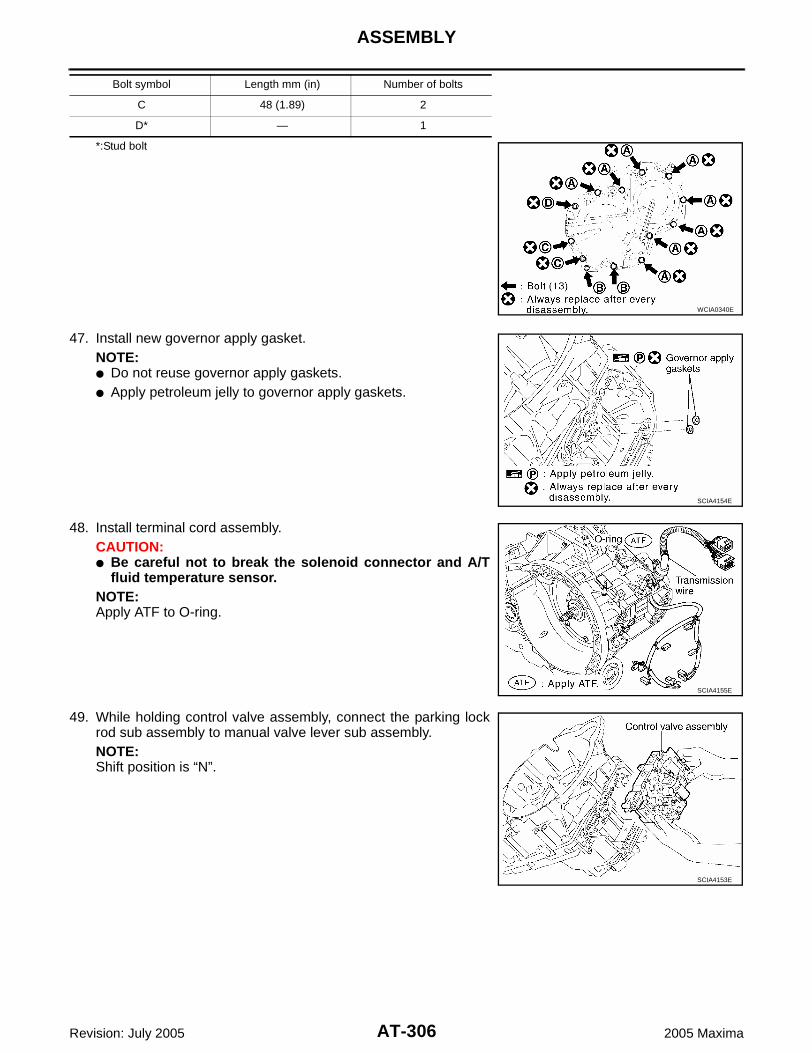
AT-306
ASSEMBLY
Revision: July 2005 2005 Maxima
*:Stud bolt
47. Install new governor apply gasket.NOTE: Do not reuse governor apply gaskets. Apply petroleum jelly to governor apply gaskets.
48. Install terminal cord assembly.CAUTION: Be careful not to break the solenoid connector and A/T
fluid temperature sensor.NOTE:Apply ATF to O-ring.
49. While holding control valve assembly, connect the parking lockrod sub assembly to manual valve lever sub assembly.NOTE:Shift position is “N”.
C 48 (1.89) 2
D* — 1
Bolt symbol Length mm (in) Number of bolts
WCIA0340E
SCIA4154E
SCIA4155E
SCIA4153E

ASSEMBLY
AT-307
D
E
F
G
H
I
J
K
L
M
A
B
AT
Revision: July 2005 2005 Maxima
50. Tighten control valve assembly bolts to specified torque. Referto AT-245, "Components" .
51. Install suction cover and new suction cover gasket in controlvalve assembly.NOTE:Do not reuse suction cover gasket.
52. Tighten new suction cover gasket and suction cover bolts tospecified torque. Refer to AT-245, "Components" .
53. Install sensor clamp and A/T fluid temperature sensor in controlvalve assembly.
54. Tighten sensor clamp bolts to specified torque. Refer to AT-245,"Components" .
Bolt symbol Length mm (in) Number of bolts
A 55 (2.17) 2
B 50 (1.97) 2
C 16 (0.63) 2
SCIA4152E
SCIA4149E
SCIA4150E
SCIA4147E
SCIA4148E

AT-308
ASSEMBLY
Revision: July 2005 2005 Maxima
55. Connect the solenoid connectors.
56. Apply silicone RTV to side cover as shown. Refer to GI-43,"Recommended Chemical Products and Sealants" .CAUTION:Complete remove all moisture, oil and sealant, etc. Fromside cover and transaxle case.
57. Install side cover in transaxle case.
58. Tighten side cover torx bolts to specified torque. Refer to AT-245, "Components" .NOTE:Do not reuse seal bolt.
SCIA4146E
SCIA5508E
SCIA4143E
SCIA4144E
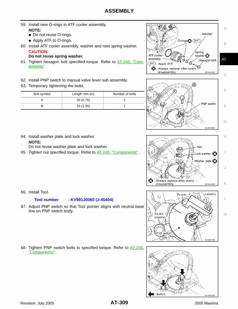
ASSEMBLY
AT-309
D
E
F
G
H
I
J
K
L
M
A
B
AT
Revision: July 2005 2005 Maxima
59. Install new O-rings in ATF cooler assembly.NOTE: Do not reuse O-rings. Apply ATF to O-rings.
60. Install ATF cooler assembly, washer and new spring washer.CAUTION:Do not reuse spring washer.
61. Tighten hexagon bolt specified torque. Refer to AT-245, "Com-ponents" .
62. Install PNP switch to manual valve lever sub assembly.63. Temporary tightening the bolts.
64. Install washer plate and lock washer.NOTE:Do not reuse washer plate and lock washer.
65. Tighten nut specified torque. Refer to AT-245, "Components" .
66. Install Tool.
67. Adjust PNP switch so that Tool pointer aligns with neutral baseline on PNP switch body.
68. Tighten PNP switch bolts to specified torque. Refer to AT-245,"Components" .
SCIA4142E
Bolt symbol Length mm (in) Number of bolts
A 20 (0.79) 1
B 33 (1.30) 1
SCIA4141E
SCIA4140E
Tool number : KV991J0060 (J-45404)
SCIA5374E
SCIA4434E

AT-310
ASSEMBLY
Revision: July 2005 2005 Maxima
69. Bend the lock washer using a flat-bladed screwdriver.
70. Install range lever in manual valve lever sub assembly.71. Tighten range lever nut to specified torque. Refer to AT-245,
"Components" .
72. Install turbine revolution sensor in transaxle case.73. Tighten turbine revolution sensor bolt to specified torque. Refer
to AT-245, "Components" .NOTE: Do not reuse seal bolt. Apply ATF to O-ring.
74. Install revolution sensor in transaxle case.75. Tighten revolution sensor bolt to specified torque. Refer to AT-
245, "Components" .NOTE: Do not reuse seal bolt. Apply ATF to O-ring.
76. Install new O-ring in A/T fluid charging pipe.NOTE: Do not reuse O-ring. Apply petroleum jelly to O-ring.
77. Install A/T fluid charging pipe in transaxle housing.78. Install A/T fluid cooler tube.
NOTE:Do not reuse copper washer.
79. Tighten A/T fluid cooler tube union to specified torque. Refer toAT-245, "Components" .
SCIA4139E
SCIA4138E
SCIA4137E
SCIA4136E
SCIA4135E

ASSEMBLY
AT-311
D
E
F
G
H
I
J
K
L
M
A
B
AT
Revision: July 2005 2005 Maxima
80. Install air breather hose.81. Install A/T fluid level gauge.
82. Install drain plug in transaxle housing.83. Tighten drain plug to specified torque. Refer to AT-245, "Components" .
NOTE:Do not reuse drain plug gasket.
84. Install torque converter.
85. Check the dimension of “A”.
CAUTION:If the distance is out of standards, adjust within standardsagain.
SCIA4134E
Dimension “A” : 14.0 mm (0.55 in)
SAT044A

AT-312
SERVICE DATA AND SPECIFICATIONS (SDS)
Revision: July 2005 2005 Maxima
SERVICE DATA AND SPECIFICATIONS (SDS) PFP:00030
General Specifications ECS00BUG
*: Refer to MA-9, "RECOMMENDED FLUIDS AND LUBRICANTS" .
Shift Schedule ECS00BUH
VEHICLE SPEED WHEN SHIFTING GEARS
Engine VQ35DE
Automatic transaxle model RE5F22A
Automatic transaxle model code number 8Y100
Stall torque ratio 1.8: 1
Transaxle gear ratio
1st 4.657
2nd 3.032
3rd 1.982
4th 1.341
5th 1.018
Reverse 5.114
Final drive 2.440
Recommended fluid Genuine Nissan Matic Fluid K*
Fluid capacity (US qt, Imp qt) 7.3 (7-3/4, 6-3/8)
CAUTION: Use only Genuine Nissan Matic Fluid K. Do not mix with other fluid.
Using automatic transaxle fluid other than Genuine Nissan Matic Fluid K will deteriorate in driveability and automatic tran-saxle durability, and may damage the automatic transaxle, which is not covered by the warranty.
Accelerator angle Vehicle speed km/h (MPH) (Approx.)
D1 →D2 D2 →D3 D3 →D4 D4 →D5 D5 →D4 D4 →D3 D3 →D2 D2 →D1
100 %59
(37)95
(59)147(91)
217(135)
207(129)
142(88)
83(52)
41(25)
90 %59
(37) 95(59)
147(91)
217(135)
207(129)
142(88)
83(52)
41(25)
80 %59
(37)95
(59)147(91)
217(135)
207(129)
142(88)
83(52)
41(25)
70 %59
(37)95
(59)147(91)
217(135)
197(122)
141(88)
81(50)
41(25)
60 %59
(37)95
(59)147(91)
217(135)
190(118)
135(84)
76(47)
41(25)
50 %59
(37)90
(56)137(85)
202(126)
176(109)
123(76)
69(43)
41(25)
40 %50
(31)82
(51)117(73)
172(107)
148(92)
92(57)
54(34)
32(20)
30 %37
(23)62
(39)87
(54)127(79)
105(65)
59(37)
35(22)
19(12)
20 %27
(17)44
(27)59
(37)87
(54)60
(37)40
(25)22
(14)8
(5)
10 %19
(12)27
(17)35
(22)55
(34)44
(27)32
(20)22
(14)8
(5)

SERVICE DATA AND SPECIFICATIONS (SDS)
AT-313
D
E
F
G
H
I
J
K
L
M
A
B
AT
Revision: July 2005 2005 Maxima
VEHICLE SPEED WHEN PERFORMING AND RELEASING COMPLETE LOCK-UP
Lock-up vehicle speed indicates the speed in D position.
Perform lock-up inspection after warming up engine.
Lock-up vehicle speed may vary depending on the driving conditions and circumstances.
VEHICLE SPEED WHEN PERFORMING AND RELEASING SLIP LOCK-UP
Slip lock-up vehicle speed indicates the speed in D position.
Perform slip lock-up inspection after warming up engine.
Slip lock-up vehicle speed may vary depending on the driving conditions and circumstances.
Stall Speed ECS00BUI
Line Pressure ECS00BUJ
Time Lag ECS00BUK
Shift Solenoid Valves ECS00BUL
Accelerator angleVehicle speed km/h (MPH) (Approx.)
Lock-up “ON” Lock-up “OFF”
50 % 217 (135) 195 (121)
15% 108 (67) 70 (43)
0 - 8 % 66 (41) 63 (39)
Accelerator angle Gear positionVehicle speed km/h (MPH) (Approx.)
Slip lock-up “ON” Slip lock-up “OFF”
0 - 10 %4th 41 (25) 38 (24)
5th 53 (33) 50 (31)
Stall speed 2,430 - 2,730 rpm
Engine speedLine pressure kPa (kg/cm2 , psi)
D, M positions R position
At idle speed 333 - 392 (3.4 - 4.0, 48 - 57) 500 - 608 (5.1 - 6.2, 73 - 88)
At stall speed 1,285 - 1,393 (13.1 - 14.2, 186 - 202) 1,706 - 1,981 (17.4 - 20.2, 247 - 287)
Selector lever Time
N to D position Less than 0.7 sec.
N to R position Less than 1.2 sec.
Shift positionShift solenoid valve
RemarksA B C D E
P OFF (Open) OFF (Closed) OFF (Closed) OFF (Open) OFF (Closed) PARK POSITION
R OFF (Open) OFF (Closed) ON (Open) OFF (Open) ON (Open) REVERSE POSITION
N OFF (Open) OFF (Closed) OFF (Closed) OFF (Open) OFF (Closed) NEUTRAL POSITION
D
1st ON (Closed) ON (Open) ON (Open) OFF (Open) OFF (Closed)
Automatic shift1 ⇔ 2 ⇔ 3 ⇔ 4 ⇔ 5
1 ⇔ 2 OFF (Open) OFF (Closed) ON (Open) OFF (Open) OFF (Closed)
2nd OFF (Open) OFF (Closed) ON (Open) OFF (Open) OFF (Closed)
2 ⇔ 3 OFF (Open) OFF (Closed) ON (Open) ON (Closed) ON (Open)
3rd OFF (Open) OFF (Closed) ON (Open) ON (Closed) OFF (Closed)
3 ⇔ 4 OFF (Open) OFF (Closed) OFF (Closed) ON (Closed) ON (Open)
4th OFF (Open) OFF (Closed) OFF (Closed) ON (Closed) OFF (Closed)
4 ⇔ 5 OFF (Open) ON (Open) OFF (Closed) ON (Closed) OFF (Closed)
5th OFF (Open) ON (Open) OFF (Closed) ON (Closed) OFF (Closed)

AT-314
SERVICE DATA AND SPECIFICATIONS (SDS)
Revision: July 2005 2005 Maxima
*: Except when automated up/down shift control and up/down shift permission control are actuated. Refer to AT-37, "MANUAL MODE" .
Solenoid Valves ECS00BUM
Specified resistance at 20°C (68°F).
Clutch and Brakes ECS00BUN
2ND BRAKE
*: Always check with the Parts Department for the latest parts information.
2ND COAST BRAKE
M5 5th OFF (Open) ON (Open) OFF (Closed) ON (Closed) OFF (Closed) Locks in 5th gear*
M4 4th OFF (Open) OFF (Closed) OFF (Closed) ON (Closed) OFF (Closed) Locks in 4th gear*
M3 3rd OFF (Open) OFF (Closed) ON (Open) ON (Closed) OFF (Closed) Locks in 3rd gear*
M2 2nd OFF (Open) OFF (Closed) ON (Open) OFF (Open) OFF (Closed) Locks in 2nd gear*
M1 1st ON (Closed) ON (Open) ON (Open) OFF (Open) ON (Open) Locks in 1st gear*
Shift positionShift solenoid valve
RemarksA B C D E
Solenoid valves Resistance (Approx.) Connector (Color) Terminal
Shift solenoid valve A
11 - 16 Ω
(B) 1 - Ground
Shift solenoid valve B (GR) 1 - Ground
Shift solenoid valve C (GR) 1 - Ground
Shift solenoid valve D (L) 1 - Ground
Shift solenoid valve E (G) 1 - Ground
Pressure control solenoid valve A
5.0 - 5.6 Ω
(G) 1 - 2
Pressure control solenoid valve B (B) 1 - 2
Pressure control solenoid valve C (L) 1 - 2
Number of 2nd brake plates 4
Number of 2nd brake discs 4
Number of 2nd brake flange 1
Piston stroke mm (in) 1.10 - 1.50 (0.0433 - 0.0591)
Thickness of 2nd brake flanges
Thickness mm (in) Part number*
3.6 (0.142)3.8 (0.150)4.0 (0.157)
31537-8Y01131537-8Y01231537-8Y013
Number of 2nd coast brake plates 3
Number of 2nd coast brake discs 3
Number of 2nd coast brake flange 1
Piston stroke mm (in) 0.76 - 1.44 (0.0299 - 0.0567)

SERVICE DATA AND SPECIFICATIONS (SDS)
AT-315
D
E
F
G
H
I
J
K
L
M
A
B
AT
Revision: July 2005 2005 Maxima
B5 BRAKE
*: Always check with the Parts Department for the latest parts information.
1ST AND REVERSE BRAKE
FORWARD AND DIRECT CLUTCH ASSEMBLY
*: Always check with the Parts Department for the latest parts information.
U/D BRAKE
*: Always check with the Parts Department for the latest parts information.
Final Drive ECS00BUO
DIFFERENTIAL SIDE BEARING ADJUSTING SHIMS
*: Always check with the Parts Department for the latest parts information.
Number of B5 brake plates 6
Number of B5 brake discs 6
Number of B5 brake flange 1
Number of B5 brake cushion plate 1
Piston stroke mm (in) 2.34 - 2.70 (0.0921 - 0.1063)
Thickness of B5 brake flanges
Thickness mm (in) Part number*
5.0 (0.197)5.1 (0.202) 5.2 (0.205)5.3 (0.209)5.5 (0.217)
31667-8Y01031667-8Y01531667-8Y01131667-8Y01331667-8Y014
Number of 1st and reverse brake plates 4
Number of 1st and reverse brake discs 5
Number of 1st and reverse brake flanges 2
Piston stroke mm (in) 1.39 - 2.21 (0.0547 - 0.0870)
Thickness of thrust washer races
Thickness mm (in) Part number*
0.81 (0.0319)1.15 (0.0453)
31435 8Y01131435 8Y012
End play mm (in) 0.305 - 0.820 mm (0.0120 - 0.0323)
Piston type Mark Piston length mm (in) Part number*
A — 63.7 (2.508) 31615 8Y005
B 1 64.2 (2.528) 31615 8Y004
C 2 64.7 (2.547) 31615 8Y003
D 3 65.2 (2.567) 31615 8Y002
E 4 65.7 (2.587) 31615 8Y001
Piston stroke mm (in) 5.76 - 6.76 mm (0.2268 - 0.2661)
Thickness mm (in) Part number* Thickness mm (in) Part number*
1.00 (0.0394)1.05 (0.0413)1.10 (0.0433)1.15 (0.0453)1.20 (0.0472)1.25 (0.0492)1.30 (0.0512) 1.33 (0.0524)1.36 (0.0535)1.39 (0.0547)1.42 (0.0559)1.45 (0.0571)
31438-8Y00131438-8Y00231438-8Y00331438-8Y00431438-8Y00531438-8Y00631438-8Y00731438-8Y00831438-8Y00931438-8Y01031438-8Y01131438-8Y012
1.48 (0.0583)1.51 (0.0594)1.54 (0.0606)1.57 (0.0618)1.60 (0.0630)1.65 (0.0650)1.70 (0.0669)1.75 (0.0689)1.80 (0.0709)1.85 (0.0728)1.90 (0.0748)
31438-8Y013 31438-8Y01431438-8Y01531438-8Y01631438-8Y01731438-8Y01831438-8Y01931438-8Y02031438-8Y02131438-8Y02231438-8Y023

AT-316
SERVICE DATA AND SPECIFICATIONS (SDS)
Revision: July 2005 2005 Maxima
TURNING TORQUE
A/T Fluid Temperature Sensor ECS00BUP
Turbine Revolution Sensor ECS00BUQ
*: Voltage with both end of 100 Ω resistance.
Revolution Sensor ECS00BUR
*: Voltage with both end of 100 Ω resistance.
Turning torque of final drive assembly 0.7 - 1.2 N·m (0.08 - 0.12kg-m, 7 - 10 in-lb)
Condition Voltage (Approx.) Resistance (Approx.)
ATF temperature
0°C (32°F) 4.0V 9.8 kΩ
20°C (68°F) 3.0V 4.2 kΩ
80°C (176°F) 0.8V 0.54 kΩ
100°C (212°F) 0.5V 0.31 kΩ
Condition Signal Voltage* (Approx.)
Connect 12V power supply and 100 Ω resistance, and then shake magnetic body.HIGH 1.2 - 1.6V
LOW 0.4 - 0.8V
Condition Signal Voltage* (Approx.)
Connect 12V power supply and 100 Ω resistance, and then shake magnetic body.HIGH 1.2 - 1.6V
LOW 0.4 - 0.8V


![U660E AUTOMATIC TRANSMISSION / TRANSAXLE: … · u660e automatic transmission / transaxle: automatic transaxle fluid: adjustment; 2013 my camry [12/2012 -] 1. precautions and work](https://img.pdfslide.us/doc/110x75/5adfe3927f8b9ac0428cc9f3/u660e-automatic-transmission-transaxle-automatic-transmission-transaxle.jpg)