Embed Size (px)
Citation preview
Circulate To: General Manager, Service Manager, Parts Manager, Warranty Manager, Service Advisors, Technicians, Body Shop Manager, Fleet Repair
c
Technical Service Bulletin
GROUP NUMBER
CAMPAIGN 18-01-032
DATE MODEL(S)
OCTOBER 2018 SONATA (LF)
SUBJECT: SONATA ENGINE DTC P1326 - WIRING INSPECTION /
INSTALLATION AND ENGINE REPLACEMENT
(SERVICE CAMPAIGN T3G)
Description: Certain 2015MY Sonata vehicles with 2.0L Turbo and 2.4L engines may experience the Check Engine warning lamp illuminated with DTC P1326. Follow the procedure to inspect the vehicle and install a wire harness extension or replacement engine based on the inspection results.
Applicable Vehicles: Certain 2015 MY Sonata (LF) vehicles with 2.0L Turbo and 2.4L engines
SST Information:
Part Name Part Number / Figure Note
Torque Wrench Socket 09314-3Q100 Only needed if engine replacement is required.
Refer to TSB 10-FL-019 for
the detailed usage instructions Injector Combustion Seal Ring
Installer 09353-2B000
Pin Release Tool
WRK0010P2R from WRK II
OR
WRKA40RT04 from WRK III
These tools are included in Wire Harness Repair Kit II and
III provided to dealers.
*** Retail Vehicles *** Dealers must perform this Campaign on all affected vehicles whenever an affected vehicle is in the shop for any maintenance or repair. When a vehicle arrives at the Service Department, access Hyundai Motor America's "Warranty Vehicle Information" screen via WEBDCS to identify open Campaigns.
IMPORTANT
SONATA P1326 – WIRING INSPECTION / INSTALL AND ENGINE R&R (SERVICE CAMPAIGN T3G)
TSB #: 18-01-032 Page 2 of 15
SUBJECT:
SUBJECT:
Part Information:
Part Name Part Number / Figure Qty Note
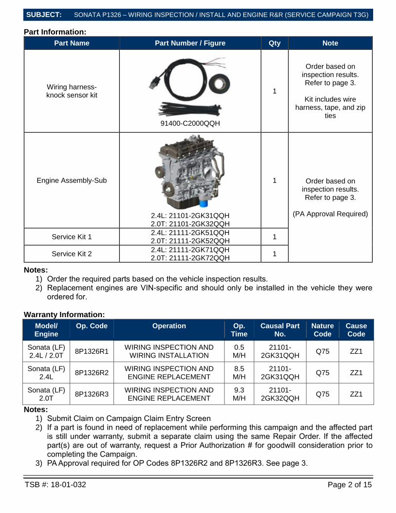
Wiring harness- knock sensor kit
91400-C2000QQH
1
Order based on inspection results. Refer to page 3.
Kit includes wire
harness, tape, and zip ties
Engine Assembly-Sub
2.4L: 21101-2GK31QQH 2.0T: 21101-2GK32QQH
1 Order based on inspection results. Refer to page 3.
(PA Approval Required)
Service Kit 1 2.4L: 21111-2GK51QQH 2.0T: 21111-2GK52QQH
1
Service Kit 2 2.4L: 21111-2GK71QQH 2.0T: 21111-2GK72QQH
1
Notes: 1) Order the required parts based on the vehicle inspection results. 2) Replacement engines are VIN-specific and should only be installed in the vehicle they were
ordered for.
Warranty Information:
Model/ Engine
Op. Code Operation Op. Time
Causal Part No.
Nature Code
Cause Code
Sonata (LF) 2.4L / 2.0T
8P1326R1 WIRING INSPECTION AND
WIRING INSTALLATION 0.5 M/H
21101-2GK31QQH
Q75 ZZ1
Sonata (LF) 2.4L
8P1326R2 WIRING INSPECTION AND ENGINE REPLACEMENT
8.5 M/H
21101-2GK31QQH
Q75 ZZ1
Sonata (LF) 2.0T
8P1326R3 WIRING INSPECTION AND ENGINE REPLACEMENT
9.3 M/H
21101-2GK32QQH
Q75 ZZ1
Notes: 1) Submit Claim on Campaign Claim Entry Screen 2) If a part is found in need of replacement while performing this campaign and the affected part
is still under warranty, submit a separate claim using the same Repair Order. If the affected part(s) are out of warranty, request a Prior Authorization # for goodwill consideration prior to completing the Campaign.
3) PA Approval required for OP Codes 8P1326R2 and 8P1326R3. See page 3.
SONATA P1326 – WIRING INSPECTION / INSTALL AND ENGINE R&R (SERVICE CAMPAIGN T3G)
TSB #: 18-01-032 Page 3 of 15
SUBJECT:
SUBJECT:
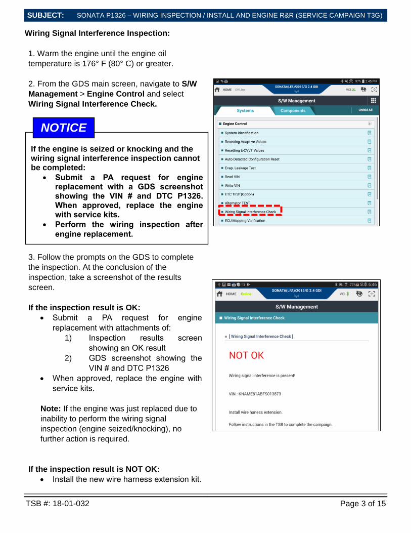
Wiring Signal Interference Inspection:
1. Warm the engine until the engine oil
temperature is 176° F (80° C) or greater.
2. From the GDS main screen, navigate to S/W
Management > Engine Control and select
Wiring Signal Interference Check.
3. Follow the prompts on the GDS to complete
the inspection. At the conclusion of the
inspection, take a screenshot of the results
screen.
If the inspection result is OK:
Submit a PA request for engine
replacement with attachments of:
1) Inspection results screen
showing an OK result
2) GDS screenshot showing the
VIN # and DTC P1326
When approved, replace the engine with
service kits.
Note: If the engine was just replaced due to
inability to perform the wiring signal
inspection (engine seized/knocking), no
further action is required.
If the inspection result is NOT OK:
Install the new wire harness extension kit.
If the engine is seized or knocking and the wiring signal interference inspection cannot be completed:
Submit a PA request for engine replacement with a GDS screenshot showing the VIN # and DTC P1326. When approved, replace the engine with service kits.
Perform the wiring inspection after
engine replacement.
NOTICE
SONATA P1326 – WIRING INSPECTION / INSTALL AND ENGINE R&R (SERVICE CAMPAIGN T3G)
TSB #: 18-01-032 Page 4 of 15
SUBJECT:
SUBJECT:
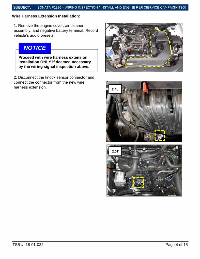
Wire Harness Extension Installation:
1. Remove the engine cover, air cleaner
assembly, and negative battery terminal. Record
vehicle’s audio presets.
2. Disconnect the knock sensor connector and
connect the connector from the new wire
harness extension.
2.0T
Proceed with wire harness extension installation ONLY if deemed necessary
by the wiring signal inspection above.
NOTICE
2.4L
SONATA P1326 – WIRING INSPECTION / INSTALL AND ENGINE R&R (SERVICE CAMPAIGN T3G)
TSB #: 18-01-032 Page 5 of 15
SUBJECT:
SUBJECT:
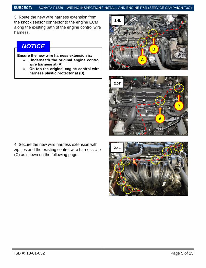
3. Route the new wire harness extension from
the knock sensor connector to the engine ECM
along the existing path of the engine control wire
harness.
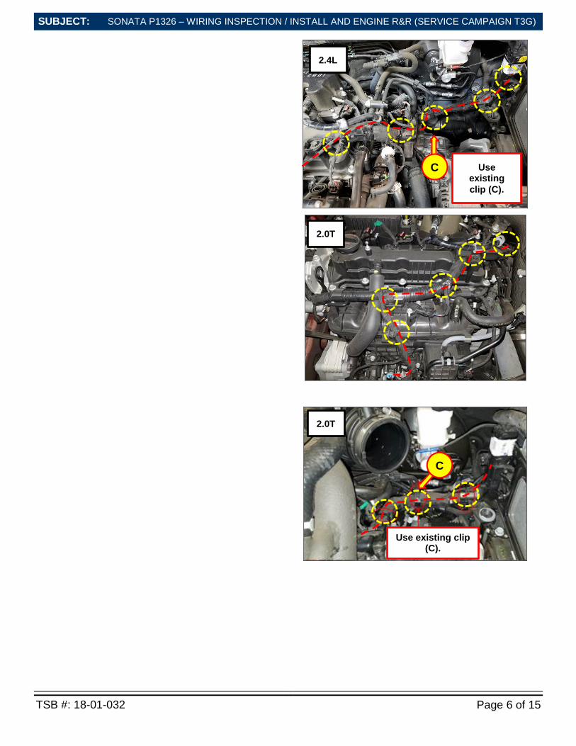
4. Secure the new wire harness extension with
zip ties and the existing control wire harness clip
(C) as shown on the following page.
Ensure the new wire harness extension is:
Underneath the original engine control wire harness at (A).
On top the original engine control wire harness plastic protector at (B).
NOTICE
A
A
2.0T
2.4L
2.4L
B
B
SONATA P1326 – WIRING INSPECTION / INSTALL AND ENGINE R&R (SERVICE CAMPAIGN T3G)
TSB #: 18-01-032 Page 6 of 15
SUBJECT:
SUBJECT:
Use existing
clip (C).
2.4L
C
Use existing clip (C).
C
2.0T
2.0T
SONATA P1326 – WIRING INSPECTION / INSTALL AND ENGINE R&R (SERVICE CAMPAIGN T3G)
TSB #: 18-01-032 Page 7 of 15
SUBJECT:
SUBJECT:
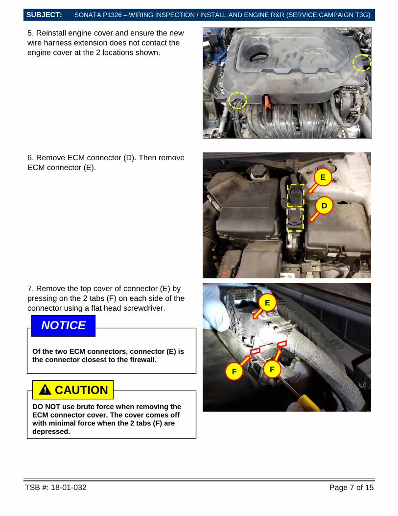
5. Reinstall engine cover and ensure the new
wire harness extension does not contact the
engine cover at the 2 locations shown.
6. Remove ECM connector (D). Then remove
ECM connector (E).
7. Remove the top cover of connector (E) by
pressing on the 2 tabs (F) on each side of the
connector using a flat head screwdriver.
D
E
F
E
Of the two ECM connectors, connector (E) is the connector closest to the firewall.
NOTICE
F
DO NOT use brute force when removing the ECM connector cover. The cover comes off with minimal force when the 2 tabs (F) are depressed.
CAUTION !
SONATA P1326 – WIRING INSPECTION / INSTALL AND ENGINE R&R (SERVICE CAMPAIGN T3G)
TSB #: 18-01-032 Page 8 of 15
SUBJECT:
SUBJECT:
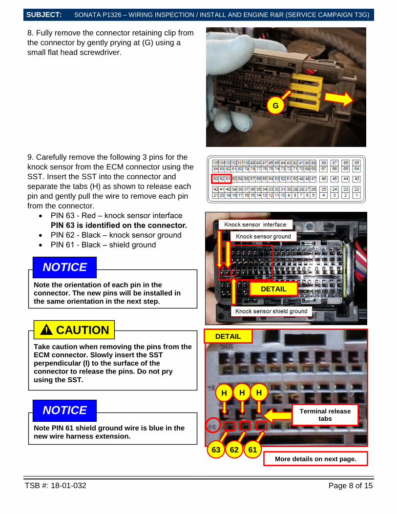
8. Fully remove the connector retaining clip from
the connector by gently prying at (G) using a
small flat head screwdriver.
9. Carefully remove the following 3 pins for the
knock sensor from the ECM connector using the
SST. Insert the SST into the connector and
separate the tabs (H) as shown to release each
pin and gently pull the wire to remove each pin
from the connector.
PIN 63 - Red – knock sensor interface
PIN 63 is identified on the connector.
PIN 62 - Black – knock sensor ground
PIN 61 - Black – shield ground
G
Note PIN 61 shield ground wire is blue in the new wire harness extension.
NOTICE
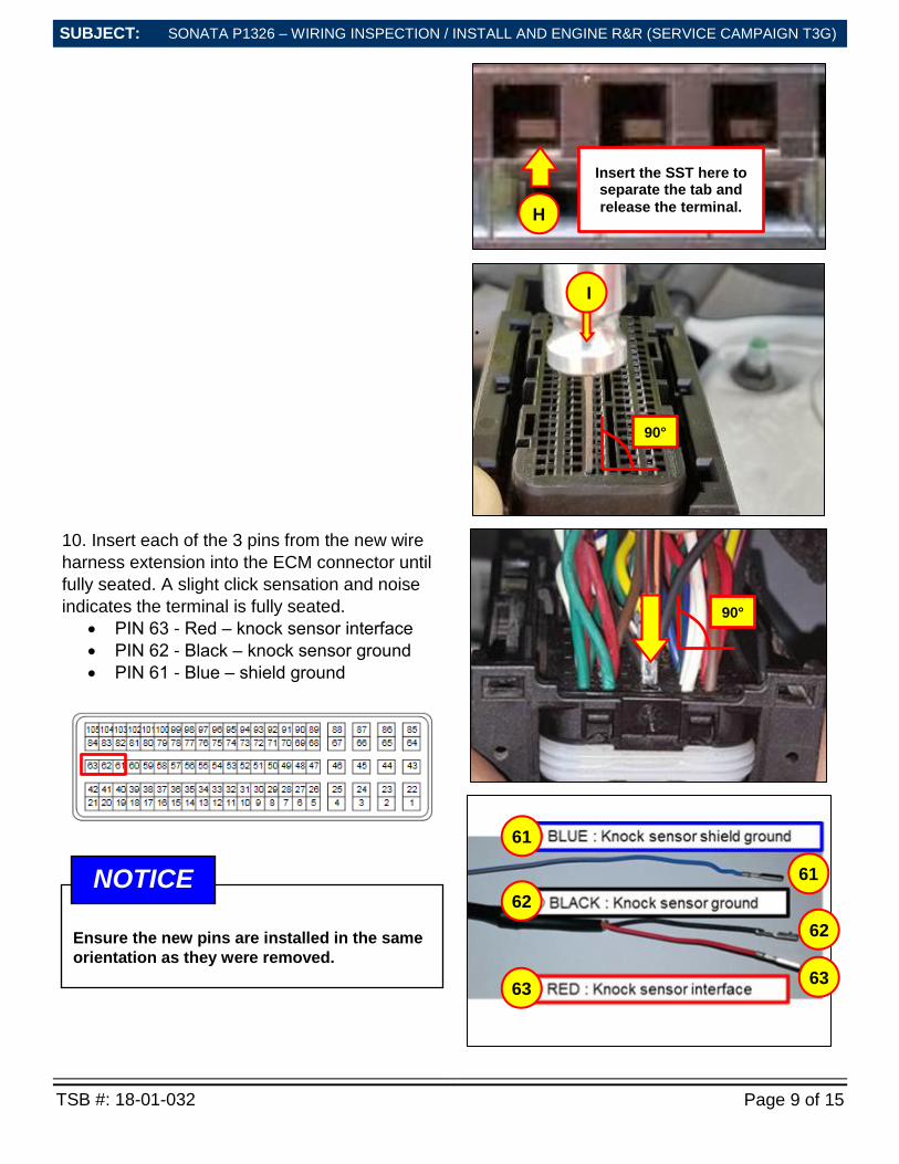
Take caution when removing the pins from the ECM connector. Slowly insert the SST perpendicular (I) to the surface of the connector to release the pins. Do not pry
using the SST.
CAUTION !
DETAIL location
(C).
DETAIL location
(C).
H
63 62 61
Terminal release tabs
location (C).
H H
Note the orientation of each pin in the connector. The new pins will be installed in the same orientation in the next step.
NOTICE
More details on next page.
SONATA P1326 – WIRING INSPECTION / INSTALL AND ENGINE R&R (SERVICE CAMPAIGN T3G)
TSB #: 18-01-032 Page 9 of 15
SUBJECT:
SUBJECT:
10. Insert each of the 3 pins from the new wire
harness extension into the ECM connector until
fully seated. A slight click sensation and noise
indicates the terminal is fully seated.
PIN 63 - Red – knock sensor interface
PIN 62 - Black – knock sensor ground
PIN 61 - Blue – shield ground
61
62
63
61
62
63
I
90°
90°
Insert the SST here to separate the tab and
release the terminal. H
Ensure the new pins are installed in the same
orientation as they were removed.
NOTICE
SONATA P1326 – WIRING INSPECTION / INSTALL AND ENGINE R&R (SERVICE CAMPAIGN T3G)
TSB #: 18-01-032 Page 10 of 15
SUBJECT:
SUBJECT:
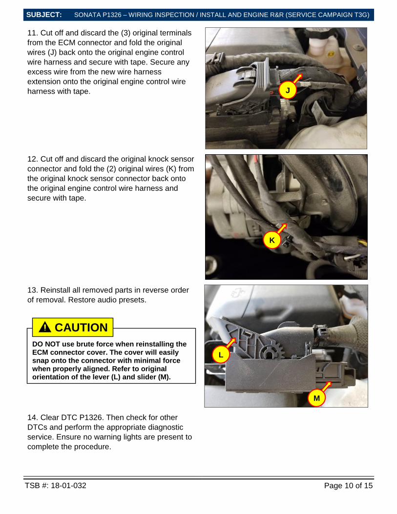
11. Cut off and discard the (3) original terminals
from the ECM connector and fold the original
wires (J) back onto the original engine control
wire harness and secure with tape. Secure any
excess wire from the new wire harness
extension onto the original engine control wire
harness with tape.
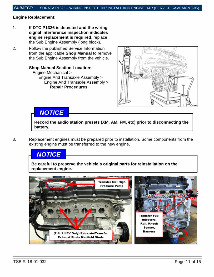
12. Cut off and discard the original knock sensor
connector and fold the (2) original wires (K) from
the original knock sensor connector back onto
the original engine control wire harness and
secure with tape.
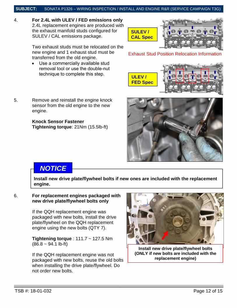
13. Reinstall all removed parts in reverse order
of removal. Restore audio presets.
14. Clear DTC P1326. Then check for other
DTCs and perform the appropriate diagnostic
service. Ensure no warning lights are present to
complete the procedure.
J
K
DO NOT use brute force when reinstalling the ECM connector cover. The cover will easily snap onto the connector with minimal force when properly aligned. Refer to original orientation of the lever (L) and slider (M).
CAUTION !
M
L
SONATA P1326 – WIRING INSPECTION / INSTALL AND ENGINE R&R (SERVICE CAMPAIGN T3G)
TSB #: 18-01-032 Page 11 of 15
SUBJECT:
SUBJECT:
Engine Replacement:
1. If DTC P1326 is detected and the wiring signal interference inspection indicates engine replacement is required, replace the Sub Engine Assembly (long block).
2. Follow the published Service Information from the applicable Shop Manual to remove the Sub Engine Assembly from the vehicle.
Shop Manual Section Location: Engine Mechanical > Engine And Transaxle Assembly > Engine And Transaxle Assembly > Repair Procedures
3. Replacement engines must be prepared prior to installation. Some components from the existing engine must be transferred to the new engine.
Be careful to preserve the vehicle’s original parts for reinstallation on the replacement engine.
NOTICE
Transfer GDI High
Pressure Pump
(2.4L ULEV Only) Relocate/Transfer
Exhaust Studs Manifold Studs
Transfer Fuel
Injectors,
Rail, Knock
Sensor,
Harness
Record the audio station presets (XM, AM, FM, etc) prior to disconnecting the battery.
NOTICE
SONATA P1326 – WIRING INSPECTION / INSTALL AND ENGINE R&R (SERVICE CAMPAIGN T3G)
TSB #: 18-01-032 Page 12 of 15
SUBJECT:
SUBJECT:
4. For 2.4L with ULEV / FED emissions only 2.4L replacement engines are produced with the exhaust manifold studs configured for SULEV / CAL emissions package. Two exhaust studs must be relocated on the new engine and 1 exhaust stud must be transferred from the old engine.
Use a commercially available stud removal tool or use the double-nut technique to complete this step.
Exhaust Stud Position Relocation Information
5. Remove and reinstall the engine knock sensor from the old engine to the new engine. Knock Sensor Fastener Tightening torque: 21Nm (15.5lb-ft)
6. For replacement engines packaged with new drive plate/flywheel bolts only If the QQH replacement engine was packaged with new bolts, install the drive plate/flywheel on the QQH replacement engine using the new bolts (QTY 7). Tightening torque : 111.7 ~ 127.5 Nm (86.8 ~ 94.1 lb-ft) If the QQH replacement engine was not packaged with new bolts, reuse the old bolts when installing the drive plate/flywheel. Do not order new bolts.
Z
SULEV / CAL Spec
ULEV / FED Spec
Install new drive plate/flywheel bolts (ONLY if new bolts are included with the
replacement engine)
Install new drive plate/flywheel bolts if new ones are included with the replacement engine.
NOTICE
SONATA P1326 – WIRING INSPECTION / INSTALL AND ENGINE R&R (SERVICE CAMPAIGN T3G)
TSB #: 18-01-032 Page 13 of 15
SUBJECT:
SUBJECT:
7. Follow the published procedure outlined in TSB 10-FL-019 to remove and reinstall the following GDI high pressure fuel system components from the existing engine to the new engine:
GDI High Pressure Pump
Fuel Injectors (4)
Fuel Delivery (Rail) Pipe The corresponding Service Kits will supply the required new parts per TSB 10-FL-019 to complete the transfer of the above existing parts.
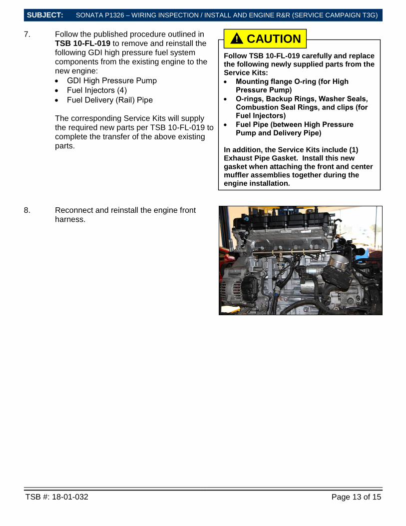
8. Reconnect and reinstall the engine front harness.
Follow TSB 10-FL-019 carefully and replace the following newly supplied parts from the Service Kits:
Mounting flange O-ring (for High Pressure Pump)
O-rings, Backup Rings, Washer Seals, Combustion Seal Rings, and clips (for Fuel Injectors)
Fuel Pipe (between High Pressure Pump and Delivery Pipe)
In addition, the Service Kits include (1) Exhaust Pipe Gasket. Install this new gasket when attaching the front and center muffler assemblies together during the engine installation.
CAUTION !
SONATA P1326 – WIRING INSPECTION / INSTALL AND ENGINE R&R (SERVICE CAMPAIGN T3G)
TSB #: 18-01-032 Page 14 of 15
SUBJECT:
SUBJECT:
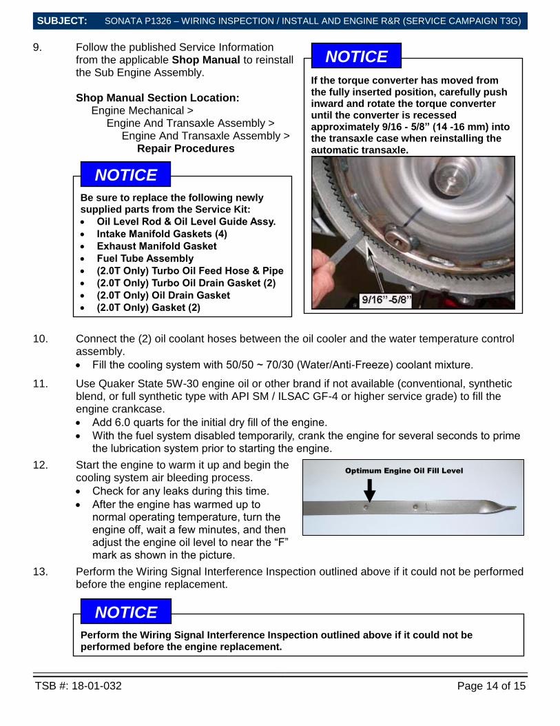
9. Follow the published Service Information from the applicable Shop Manual to reinstall the Sub Engine Assembly. Shop Manual Section Location: Engine Mechanical > Engine And Transaxle Assembly > Engine And Transaxle Assembly > Repair Procedures
10. Connect the (2) oil coolant hoses between the oil cooler and the water temperature control assembly.
Fill the cooling system with 50/50 ~ 70/30 (Water/Anti-Freeze) coolant mixture.
11. Use Quaker State 5W-30 engine oil or other brand if not available (conventional, synthetic blend, or full synthetic type with API SM / ILSAC GF-4 or higher service grade) to fill the engine crankcase.
Add 6.0 quarts for the initial dry fill of the engine.
With the fuel system disabled temporarily, crank the engine for several seconds to prime the lubrication system prior to starting the engine.
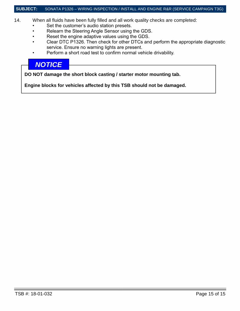
12. Start the engine to warm it up and begin the cooling system air bleeding process.
Check for any leaks during this time.
After the engine has warmed up to normal operating temperature, turn the engine off, wait a few minutes, and then adjust the engine oil level to near the “F” mark as shown in the picture.
13. Perform the Wiring Signal Interference Inspection outlined above if it could not be performed before the engine replacement.
Be sure to replace the following newly supplied parts from the Service Kit:
Oil Level Rod & Oil Level Guide Assy.
Intake Manifold Gaskets (4)
Exhaust Manifold Gasket
Fuel Tube Assembly
(2.0T Only) Turbo Oil Feed Hose & Pipe
(2.0T Only) Turbo Oil Drain Gasket (2)
(2.0T Only) Oil Drain Gasket
(2.0T Only) Gasket (2)
NOTICE
Optimum Engine Oil Fill Level
If the torque converter has moved from the fully inserted position, carefully push inward and rotate the torque converter until the converter is recessed approximately 9/16 - 5/8” (14 -16 mm) into the transaxle case when reinstalling the automatic transaxle.
NOTICE
Perform the Wiring Signal Interference Inspection outlined above if it could not be performed before the engine replacement.
NOTICE
SONATA P1326 – WIRING INSPECTION / INSTALL AND ENGINE R&R (SERVICE CAMPAIGN T3G)
TSB #: 18-01-032 Page 15 of 15
SUBJECT:
SUBJECT:
14. When all fluids have been fully filled and all work quality checks are completed: • Set the customer’s audio station presets. • Relearn the Steering Angle Sensor using the GDS. • Reset the engine adaptive values using the GDS. • Clear DTC P1326. Then check for other DTCs and perform the appropriate diagnostic
service. Ensure no warning lights are present. • Perform a short road test to confirm normal vehicle drivability.
DO NOT damage the short block casting / starter motor mounting tab.
Engine blocks for vehicles affected by this TSB should not be damaged.
NOTICE