Embed Size (px)
Citation preview
4–22.
The tool at A is used to hold a power lawnmower bladestationary while the nut is being loosened with the wrench.If a force of 50 N is applied to the wrench at B in the directionshown, determine the moment it creates about the nut at C.What is the magnitude of force F at A so that it creates theopposite moment about C?
SOLUTIONc
Ans.
a
Ans.F = 35.2 N
+ MA = 0; -12.99 + Fa 1213b(0.4) = 0
MA = 12.99 = 13.0 N # m
+ MA = 50 sin 60°(0.3)
F
400 mm
300 mm
60
50 N
B
A
C
125
13
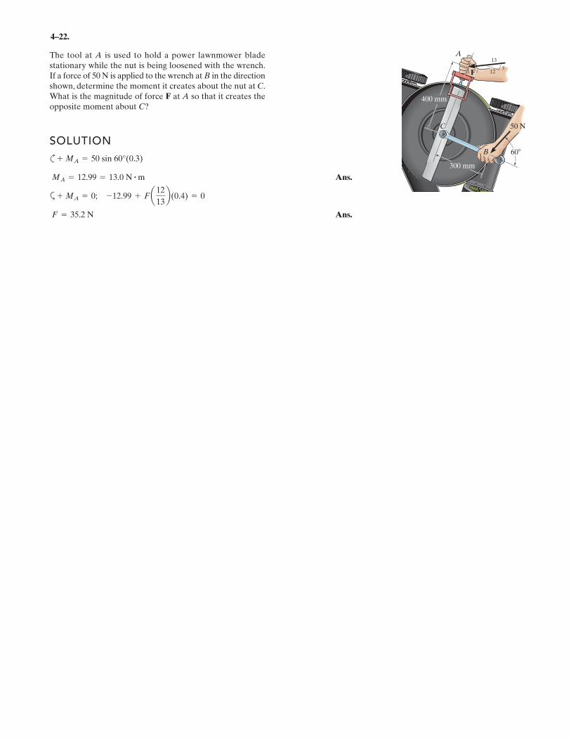
4–29.
The connected bar BC is used to increase the lever arm ofthe crescent wrench as shown. If a clockwise moment of
is needed to tighten the nut at A and theextension d = 300 mm, determine the required force F inorder to develop this moment.
SOLUTION
By resolving force F into components parallel and perpendicular to the box wrenchBC, Fig. a, the moment of F can be obtained by adding algebraically the momentsof these two components about point A in accordance with the principle ofmoments.
a
Ans.F = 239 N
+(MR)A = ©Fd; -120 = F sin 15°(0.3 sin 30°) - F cos 15°(0.3 cos 30° + 0.3)
MA = 120 N # m
300 mm
30�
15�d
C
B
A
F

4–63.
The pipe assembly is secured on the wall by the twobrackets. If the frictional force of both brackets can resist amaximum moment of , determine the largestweight of the flower pot that can be supported by theassembly without causing it to rotate about the OA axis.
150 lb # ft
A
O
z
x y
4 ft
3 ft
3 ft
4 ft60
30B
SOLUTIONMoment About the OA Axis: The coordinates of point B are
.
Either position vector or can be used to determine the moment of W about
the OA axis.
Since W is directed towards the negative z axis, we can write
The unit vector uOA, Fig. a, that specifies the direction of the OA axis is given by
Since it is required that the magnitude of the moment of W about the OA axis notexceed , we can write
Ans.
or
Ans.W = 56.8 lb
150 = 0 -45
[3.299(-W) - 0(0)] +35
[3.299(0) - 0(5.714)]
150 = 5 045
35
3.299 5.714 00 0 -W
5MOA = uOA
# rAB * W
W = 56.8 lb
150 = 0 -45
[3.299(-W) - 0(1.5)] +35
[3.299(0) - 0(5.714)]
150 = 5 045
35
3.299 5.714 1.50 0 -W
5MOA = uOA
# rOB * W
150 ft # lb
uOA =(0 - 0)i + (4 - 0)j + (3 - 0)k
2(0 - 0)2 + (4 - 0)2 + (3 - 0)2=
45
j +35
k
W = -Wk
rAB = (3.299 - 0)i + (5.714 - 4)j + (1.5 - 3)k = [3.299i + 1.714j - 1.5k] ft
rOA = (3.299 - 0)i + (5.714 - 0)j + (1.5 - 0)k = [3.299i + 5.714j + 1.5k] ft
rOCrOB
[(4 + 3 cos 30°) cos 60°, (4 + 3 cos 30°) sin 60°, 3 sin 30°]ft = (3.299, 5.174, 1.5) ft

*4–76.
Determine the magnitude of the couple force F so that the resultant couple moment on the crank is zero.
SOLUTIONBy resolving F and the 150-lb couple into components parallel and perpendicular to the lever arm of the crank, Fig. a, and summing the moment of these two force components about point A, we have
a
Ans.
Note: Since the line of action of the force component parallel to the lever arm of the crank passes through point A, no moment is produced about this point.
F = 194 lb
+(MC)R = ©MA; 0 = 150 cos 15°(10) - F cos 15°(5) - F sin 15°(4) - 150 sin 15°(8)
150 lb
150 lb
30� 30�
45�45�30�
30�
F
–F5 in.
5 in.
4 in.
4 in.
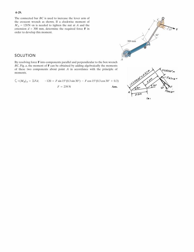
4–95.
If , and , determine themagnitude and coordinate direction angles of the resultantcouple moment.
SOLUTIONCouple Moment: The position vectors r1, r2, r3, and r4, Fig. a, must be determinedfirst.
From the geometry of Figs. b and c, we obtain
The force vectors F1, F2, and F3 are given by
Thus,
Resultant Moment: The resultant couple moment is given by
The magnitude of the couple moment is
Ans.
The coordinate angles of (Mc)R are
Ans.
Ans.
Ans.g = cos -1a [(Mc)R]z
(Mc)Rb = cos a -16
71.94b = 103°
b = cos -1a [(Mc)R]y
(Mc)Rb = cos a -47.56
71.94b = 131°
a = cos -1a [(Mc)R]x
(Mc)Rb = cos a51.56
71.94b = 44.2°
= 71.94 N # m = 71.9 N # m
= 2(51.56)2+ (-47.56)2
+ (-16)2
(Mc)R = 2[(Mc)R] 2x + [(Mc)R] 2
y + [(Mc)R] 2z
= {51.56i - 47.56j - 16k} N # m
= (-20j) + (24i) + (-16k) + (27.56i-27.56j)
(Mc)R = M1 + M2 + M3 + M4(Mc)R = ∑Mc;
M4 = r4 * F4 = (0.1837i + 0.1837j - 0.15k) * (150k) = {27.56i - 27.56j} N # m
M3 = r3 * F3 = (0.2j) * (80i) = {-16k} N # m
M2 = r2 * F2 = (0.2j) * (120k) = {24i} N # m
M1 = r1 * F1 = (0.2i) * (100k) = {-20j} N # m
F3 = {80i} NF2 = {120k} NF1 = {100k} N
= {0.1837i + 0.1837j - 0.15k} m
r4 = 0.3 cos 30° cos 45°i + 0.3 cos 30° sin 45°j - 0.3 sin 30°k
r3 = {0.2j} mr2 = {0.2j} mr1 = {0.2i} m
F3 = 80 NF2 = 120 NF1 = 100 N
– F1y
x
z
0.2 m
0.2 m
0.2 m
0.2 m
0.2 m
0.2 m
0.3 m
0.3 m
30�
– F2
F1
–F4 � [�150 k] N
F4 � [150 k] N
F2
– F3
F3

*4–96.
Determine the required magnitude of F1, F2, and F3so that the resultant couple moment is
.
SOLUTIONCouple Moment: The position vectors r1, r2, r3, and r4, Fig. a, must be determinedfirst.
From the geometry of Figs. b and c, we obtain
The force vectors F1, F2, and F3 are given by
Thus,
Resultant Moment: The resultant couple moment required to equal . Thus,
Equating the i, j, and k components yields
Ans.
Ans.
Ans.F3 = 100 N-20 = -0.2F3
F1 = 87.2 N-45 = -0.2F1 - 27.56
F2 = 112 N50 = 0.2F2 + 27.56
50i - 45j - 20k = (0.2F2 + 27.56)i + (-0.2F1 - 27.56)j - 0.2F3k
50i - 45j - 20k = (-0.2F1j) + (0.2F2i) + (-0.2F3k) + (27.56i - 27.56j)
(Mc)R = M1 + M2 + M3 + M4(Mc)R = ©Mc;
(Mc)R = {50i - 45j - 20k} N # m
M4 = r4 * F4 = (0.1837i + 0.1837j - 0.15k) * (150k) = {27.56i - 27.56j} N # m
M3 = r3 * F3 = (0.2j) * (F3i) = -0.2 F3k
M2 = r2 * F2 = (0.2j) * (F2k) = 0.2 F2i
M1 = r1 * F1 = (0.2i) * (F1k) = -0.2 F1j
F3 = F3iF2 = F2kF1 = F1k
= {0.1837i + 0.1837j - 0.15k} m
r4 = 0.3 cos 30° cos 45°i + 0.3 cos 30° sin 45°j - 0.3 sin 30°k
r3 = {0.2j} mr2 = {0.2j} mr1 = {0.2i} m
[50 i - 45 j - 20 k] N # m(Mc)R =
– F1y
x
z
0.2 m
0.2 m
0.2 m
0.2 m
0.2 m
0.2 m
0.3 m
0.3 m
30�
– F2
F1
–F4 � [�150 k] N
F4 � [150 k] N
F2
– F3
F3

*4–112.
Handle forces F1 and F2 are applied to the electric drill.Replace this force system by an equivalent resultant forceand couple moment acting at point O. Express the results inCartesian vector form.
SOLUTION
Ans.
Ans.
Note that pushes the drill bit down into the stock.
and cause the drill bit to bend.
causes the drill case and the spinning drill bit to rotateabout the z-axis.(MRO)z = -0.450 N # m
(MRO)y = 3.30 N # m(MRO)x = 1.30 N # m
FRz = -14 N
= {1.30i + 3.30j - 0.450k} N # m
= 0.9i + 3.30j - 0.450k + 0.4i
MRO = 3 i j k0.15 0 0.3
6 -3 -10
3 + 3 i j k0 -0.25 0.30 2 -4
3 MRO = ©MO ;
= {6i - 1j - 14k} N
FR = ©F; FR = 6i - 3j - 10k + 2j - 4k x y
z
0.25 m
0.3 mO
F1 � {6i � 3j � 10k} N
F2 � {2j � 4k} N
0.15 m

4–134.
Replace the two wrenches and the force, acting on the pipeassembly, by an equivalent resultant force and couplemoment at point O.
SOLUTIONForce And Moment Vectors:
Equivalent Force and Couple Moment At Point O:
Ans.
The position vectors are and
Ans.= 122i - 183k N # m
+ 100k + 127.28i - 127.28k
+i j k0 1.1 0
141.42 0 -141.42
= 3 i j k0 0.5 00 0 300
3MRO
= r1 * F1 + r2 * F2 + M1 + M2MRO= ©MO ;
r2 = 51.1j6 m.r1 = 50.5j6m
= 5141i + 100j + 159k6 N
= 141.42i + 100.0j + 1300 - 141.422kFR = F1 + F2 + F3FR = ©F;
= 5127.28i - 127.28k6 N # m
M2 = 1805cos 45°i - sin 45°k6 N # m
M1 = 5100k6 N # m
= 5141.42i - 141.42k6 N
F2 = 2005cos 45°i - sin 45°k6 N
F1 = 5300k6 N F3 = 5100j6 N
A BO
z
200 N
180 N · m
C y
x
45°
100 N
100 N · m
300 N
0.6 m 0.8 m0.5 m
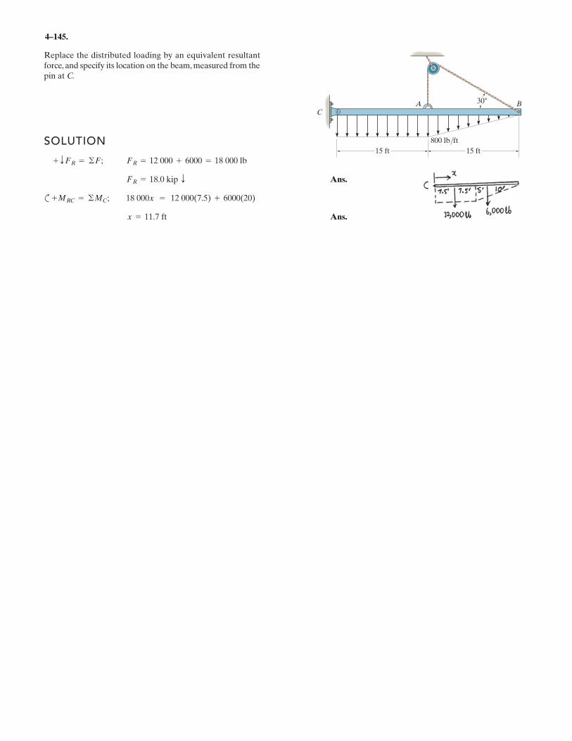
4–145.
Replace the distributed loading by an equivalent resultantforce, and specify its location on the beam, measured from thepin at C.
SOLUTION
Ans.
c
Ans.x = 11.7 ft
+MRC = ©MC; 18 000x = 12 000(7.5) + 6000(20)
FR = 18.0 kip T
+ TFR = ©F; FR = 12 000 + 6000 = 18 000 lb
CA B
15 ft 15 ft
30
800 lb/ft

*4–156.
Replace the distributed loading with an equivalent resultantforce, and specify its location on the beam measured frompoint A.
SOLUTIONResultant: The magnitude of the differential force is equal to the area of theelement shown shaded in Fig. a. Thus,
Integrating dFR over the entire length of the beam gives the resultant force .
Ans.
Location: The location of on the beam is measured from point A. Thus,the location of measured from point A is given by
Ans.x =
LLxcdFR
LLdFR
=
L
L
0x¢w0 sin
p
2Lx≤dx
2w0L
p
=
4w0L2
p2
2w0L
p
=
2Lp
FRxxc = xdFR
+ T FR =
LL dFR =
L
L
0¢w0 sin
p
2Lx≤dx = ¢- 2w0L
p cos
p
2L x≤ ` L
0=
2w0L
p T
FR
dFR = w dx = ¢w0 sin p
2L x≤dx
dFR
w
x
––2Lw � w0 sin ( x)
w0
L
A
p

*4–160.
SOLUTIONEquivalent Resultant Force And Moment At Point O:
Ans.
a
(Clockwise) Ans.= 19.4 kN # m
= -19 440 N # m
= -L9 m
0A200x
32 Bdx
= -L9 m
0x A200x
12 Bdx
MRO= -L
x
0xwdx+ MRO
= ©MO ;
= -3600 N = 3.60 kN T
FR = -L9 m
0A200x
12 Bdx
FR = -LAdA = -L
x
0wdx+ c FR = ©Fy ;
Replace the loading by an equivalent force and couplemoment acting at point O.
x
w
9 m
600 N/mw = (200x ) N/m1––2
O
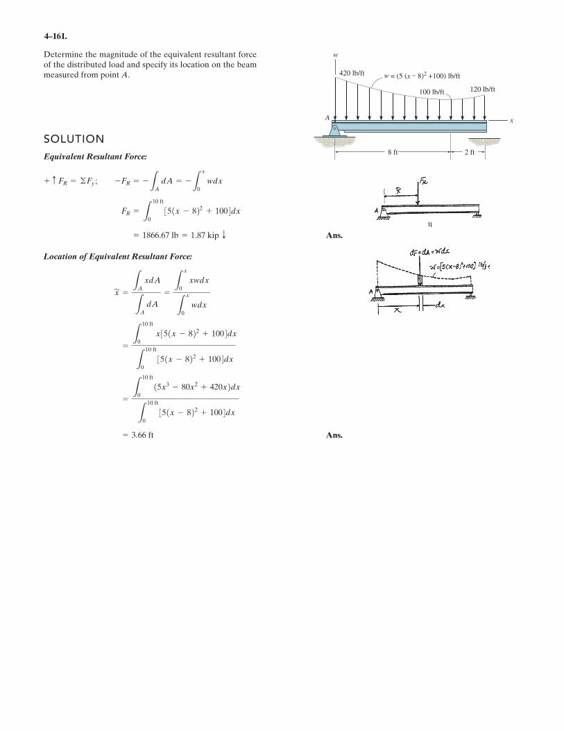
4–161.
Determine the magnitude of the equivalent resultant forceof the distributed load and specify its location on the beammeasured from point A.
SOLUTIONEquivalent Resultant Force:
Ans.
Location of Equivalent Resultant Force:
Ans.= 3.66 ft
= L10 ft
015x3 - 80x2 + 420x2dx
L10 ft
0351x - 822 + 1004dx
= L10 ft
0x351x - 822 + 1004dx
L10 ft
0351x - 822 + 1004dx
x' = LA
xdA
LAdA
= Lx
0xwdx
Lx
0wdx
= 1866.67 lb = 1.87 kip T
FR = L10 ft
0351x - 822 + 1004dx
-FR = -LAdA = -L
x
0wdx+ c FR = ©Fy ;
A
= (5 (x – 8)2 +100) lb/ft
w
8 ft 2 ft
120 lb/ft100 lb/ft
420 lb/ft w
x