Embed Size (px)
Citation preview

1 C series service training
C series service training

2 C series service training
1 General
2 Frame / steering
4
Power train 3
Engine
5 Wheelmotor / brake
6 Drive hydraulics
Service
Working hydraulics
Electrics
Maintenance
Trouble shooting on the vehicle
7
8
9
10
3 C series service training
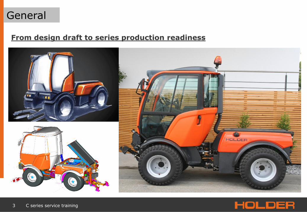
General
From design draft to series production readiness

4 C series service training
General
Dimensions
Wheelbase 1700
Track 882 – 1214 (205/60R15)
Track
Flange dimension 1040
Cab width 1100

5 C series service training
General
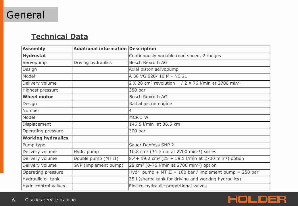
Technical Data
Engine technical data
Vehicle type C 250/C 350 C 270/C 370
Manufacturer Kubota Kubota
Model designation V2607-DI-EU3 V2607-DI-T-EU3
Cooling Water Water
Mode of operation Four-stroke diesel Four-stroke diesel
Number of cylinders 4 cylinders 4 cylinders
Displacement 2615 cm3 2615 cm3
Fuel consumption corresponds to 220g/KW-h at 1600 min1 220g/KW-h at 1600 min1
approx. 6.3 l/h approx. 8.7 l/h
Rated speed 2,700 min-1 2,700 min1
Upper idling speed 2700± 200 min1 2700± 200 min1
Lower idling speed 850± 25 min1 850± 25 min1
Power according to 97/68/EG n = 2700 min1 36.5 KW / 50 HP 48.5 KW / 67 HP
Exhaust standard 2000/25/EG/97/68/EG Level IIIA Level IIIA
Highest torque according to 97/68EG 167.5 Nm at 1600 min x 217.0 Nm at 1600 min 1
6 C series service training
General
Technical Data
Assembly Additional information Description
Hydrostat Continuously variable road speed, 2 ranges
Servopump Driving hydraulics Bosch Rexroth AG
Design Axial piston servopump
Model A 30 VG 028/ 10 M - NC 21
Delivery volume 2 X 28 cm3 revolution / 2 X 76 l/min at 2700 min-1
Highest pressure 350 bar
Wheel motor Bosch Rexroth AG
Design Radial piston engine
Number 4
Model MCR 3 W
Displacement 146.5 l/min at 36.5 km
Operating pressure 300 bar
Working hydraulics
Pump type Sauer Danfoss SNP 2
Delivery volume Hydr. pump 10.8 cm3 (34 l/min at 2700 min-1) series
Delivery volume Double pump (MT II) 8.4+ 19.2 cm3 (25 + 59.5 l/min at 2700 min-1) option
Delivery volume GVP (implement pump) 28 cm3 (0-76 l/min at 2700 min-1) option
Operating pressure Hydr. pump + MT II = 180 bar / implement pump = 250 bar
Hydraulic oil tank 35 l (shared tank for driving and working hydraulics)
Hydr. control valves Electro-hydraulic proportional valves

7 C series service training
General
Technical Data Assembly Additional
information Description
Steering
Type Hydrostatic with 2 steering cylinders, double action
Steering angle Orbitrol OSPC 125 LS (single-stage) / OSPD 125/205 (two-stage)
Oil supply 35 l (shared tank for driving and working hydraulics)
Brakes
Service brakes Knott drum brakes, 250 x 55 hydraulic servo
Parking brake Knott drum brakes, 250 x 55 hydraulic servo
Actuation Electrical parking brake/hydraulic service brake
Front lift
Model Holder standard three-point. upper link adjustable
Cat. size Cat 1N -Cat 1
Lifting capacity 1100 kg (measured at the catch hook)
Lifting height approx. 610 mm depending on tyres
Cylinders 2, double-acting
Oil supply 35 l (shared tank for driving and working hydraulics)
Rear lift see front lift
Lifting height approx. 600 mm depending on tyres

8 C series service training
General
Technical Data Assembly Additional
information
Description
Electrical system
Operating voltage 12 V DC
Battery 12 V/88 Ah
Rotary current generator
14 V/90 A - 1080W
Starter motor 12 V/1.4 kW (starter)
Carriage
Inside dimension 1250 mm X 1060 mm X 300 mm + (300 mm option)
Inside dimension 1250 mm X 1,330 mm X 300 mm + (300 mm option)
Payload max 800 kg sm. cargo bed/ max 1000 kg lg. cargo bed
PTO shaft Front and rear, clockwise rotation (as viewed onto the PTO shaft)
Type of clutch front, electromagnetic pole friction clutch
Rear rotational speed 540 min1 hydraulically driven
Front rotational speed 1000 min-1 (540 min-1 option) mechanically driven
Spline shaft profile 1 3/8" (6) DIN 9611
Fuel system
Fuel tank Diesel fuel 65 I

9 C series service training
General
Technical Data
Theoretical road speed in km/h at 2700 min1
Tyres Type of wheel C 250/27 deep version C 250/270 high version
Range 1 Range 2 Range 1 Range 2
205/70 R15C 212-31-02 31.3 km/h 15.6 km/h 31.3 km/h 15.6 km/h
200/60-14,5 212-31-03 28.6 km/h 14.3 km/h 28.6 km/h 14.3 km/h
27X10.5-15 212-31-05 30.3 km/h 15.6 km/h X X
31x15.50-15 4131-8 X X 35.1 km/h 17.6 km/h
31x15.50-15 203-31-2 X X 34.9 km/h 17.4 km/h
31X10.50 R15 212-31-05 X X 36.1 km/h 18.0 km/h

10 C series service training
General
Permissible weights
Perm. gross weight in kg:
Vehicle C 250/C 270
Empty weight depending on version, equipment and tyres
from 1780 kg to 2200 kg
Perm. gross weight 3200 kg
Perm. front axle load 2000 kg
Perm. rear axle load 2000 kg
Trailer weight, unbraked 750 kg
Trailer weight, overrunning brakes 3000 kg
Permissible total weight in kg with 25 km/h limit
Vehicle C 250/C 270
Empty weight depending on version, equipment and tyres
from 1780 kg to 2300 kg
Perm. gross weight 3500 kg
Perm. front axle load 2300 kg
Perm. rear axle load 2300 kg
Trailer weight, unbraked 750 kg
Trailer weight, overrunning brakes 3000 kg

11 C series service training
General
Operating console swivels along with the seat
Direction control via toggle switch on joystick
A number of driving and working ranges are available
Speed control possible via pedals or potentiometer on the joystick
Rotational speed control via manual gas control
Air-sprung seat with arm rests on both sides (optional)
Horizontal and vertical adjustment possibilities
Comfort

12 C series service training
General
Display
1. Fuel gauge 2. Left flashing warning light 3. Engine tachometer with marking for PTO shaft
speed 4. Left flashing indicator light 5. Cooling water temperature gauge 6. Full beam indicator lamp 7. Dipped beam indicator light 8. Flashing light 2, trailer indicator light 9. Flashing light 1, trailer indicator light 10. Operating hours counter and digital km/h
display 11. Preheating indicator light 12. Differential lock indicator light 13. Parking brake indicator light 14. Cooling water temperature indicator light 15. Engine oil pressure indicator light 16. Battery indicator light

13 C series service training
General
Operation 1. Signal horn button 2. Turn signal, full/dipped beam and wiper
lever 3. Steering wheel 4. Multifunction display 5. Coding button for km/h display 6. Air outlet nozzles 7. Ignition switch
Gas pedal 8. Brake pedal 9. Electrical parking brake 10. Switch for two-stage steering * 11. Warning light switch 12. Front window heating switch * 13. Dipped beam up-down switch 14. Light switch 15. Inch pedal 16. Steering column tilt adjustment

14 C series service training
General
Operation
Right operating console (with small joystick) (contains optional equipment *)
1. Volume divider, circuit 2 40-60 l/min A)
1a. Volume regulator, circuit 2 A)
2. Volume regulator, circuit 1 2a. Volume regulator, circuit 1 3. Tipping system or rear lift 3a. Floating position button for switch 3 4. Hydraulic plug-type coupling switch, yellow 4a. Floating position button for coupling, yellow 5. Hydraulic plug-type coupling switch, blue 5a Floating position button for coupling, blue 6. Hydraulic plug-type coupling switch, green 6a. Floating position button for coupling, green 7. Switch for differential lock 8. Driving programme switch 9. Directional switch 9a. Direction indicator 10. Illumination diode for operating console 11. Joystick for working hydraulics for front lift up/down, left/right hydr. coupling 11a. floating position (11d) joystick left/right coupling, black 11b. Floating position indicator light (11c) front lift 11c . Front lift joystick floating position 11d. Change hydr. plug-type coupling from black to green (hold button pressed) joystick operation left/right 12. Fine adjustment wheel for road speed (in ranges 3 and 4) 13. Switch for working hydraulics on and off 14. Volume adjustment for hydr. couplings (tipping unit or rear lift / 4 yellow 5 blue / 6 green) 15. Switch for front PTO shaft A) Alternative implement servopump*

15 C series service training
General
Operation
Right operating console (with large joystick) (contains optional equipment *)
1. Volume divider, circuit 2 40-60 l/min A)
1a. Volume regulator circuit 2 A)
2. Volume divider circuit 1 0-25 l/min 2a. Volume regulator, circuit 1 3. Tipping system or rear lift switch 3a. Floating position button for switch 3 4. Hydraulic plug-type coupling switch, yellow 4a. Floating position button for coupling, yellow 5. Hydraulic plug-type coupling switch, blue 5a. Floating position button for coupling, blue 6a. Floating position button for coupling, green 7. Switch for differential lock 8. Driving mode programme switch 9. Directional switch 9a. Direction display 10. Illumination diode for operating console 11. Joystick for working hydraulicsfront lift up/down left/right Hydr. coupl. 11a Floating position (11d) joystick left/right coupling, black 11b Control light floating position (11c) front lift 11c Front lift joystick floating position 11d Change hydr. plug-type coupling from black to green (hold button pressed) joystick operation left/right 12. Fine adjustment wheel for road speed (in ranges 3 and 4) 13. Switch for working hydraulics on and off 14. Volume adjustment for hydr. couplings (tipping unit or rear lift / 4 yellow 5 blue) 15. Switch for front PTO shaft
A) Alternative implement servopump*

16 C series service training
General
Operation
Front upper bar control elements (contains optional equipment*)
1. Rotary switch for fan 2. Heating temperature controller 3. Switch, air-conditioning system 4. Beacon switch 5. Switch, working spotlight front* 6. Switch, working spotlight, rear 7. Mirror heating switch * 8. Seat heater switch *
Control elements in the right armrest (contains optional equipment*)
1. Armrest adjustment lever 2. Double-acting/single acting front lift switch 3. Selector switch, front lift inclination adjustment 4. Arm rest

17 C series service training
General
3 standardised attachment spaces
Universal attachment interfaces
thereby wide variety of attached implements
Replacement of attachments by 1 person and
without tools in the shortest possible time
Versatility

18 C series service training
General
Variability of the rear section

19 C series service training
General
Examples of applications
20 C series service training
General
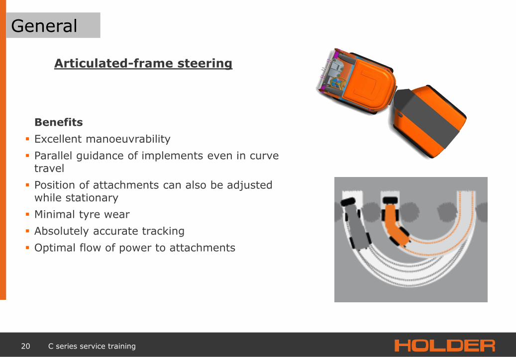
Benefits
Excellent manoeuvrability
Parallel guidance of implements even in curve travel
Position of attachments can also be adjusted while stationary
Minimal tyre wear
Absolutely accurate tracking
Optimal flow of power to attachments
Articulated-frame steering

21 C series service training
General
Front and rear ends connected independently of one another via the articulated link
The combined hydraulic stabilizer ensures maximum traction and stability in any terrain
Hydraulic stabilizer

22 C series service training
1 General
2 Frame / steering
4
Power train 3
Engine
5 Wheelmotor / brake
6 Drive hydraulics
Service
Working hydraulics
Electrics
Maintenance
Trouble shooting on the vehicle
7
8
9
10

23 C series service training
Frame
The frame consists of two separate parts (front and rear end) that are movably connected to one another via the articulated link.

24 C series service training
Frame
Articulated link (adjustable spherical bearing)
Pendulum
Link pin
Rear cab bearing

25 C series service training
Frame
Hydraulic stabilizer
Front lift
Front lift load
Control block
Zylinders
Pressure, hydraulic-stabelizer
26 C series service training
Frame
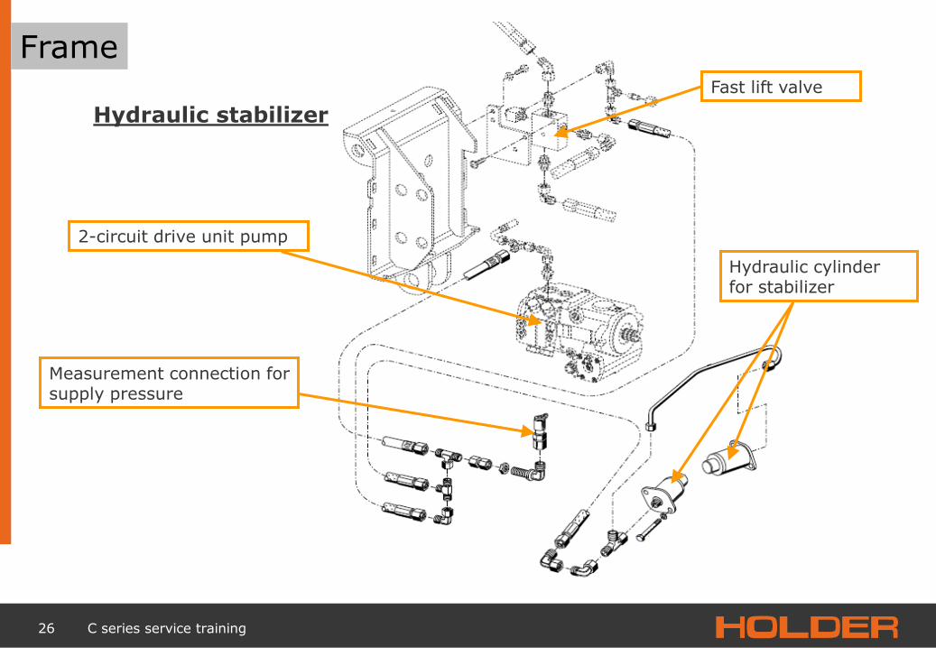
Hydraulic stabilizer
Fast lift valve
Hydraulic cylinder for stabilizer
2-circuit drive unit pump
Measurement connection for supply pressure

27 C series service training
Frame
Opposite spring Main spring
Axis suspension The suspension element is resistant to oil, petrol, diesel, grease and salt
Axle bearing

28 C series service training
Frame
Axles
Axle body
Spring elements
Axle suspension

29 C series service training
Frame
Cab lifting cylinder
Coupling sleeve for connection to a pump
Tilting cylinder

30 C series service training
Steering
Steering servo
Connection plate
Steering cylinder

31 C series service training
Steering
The vehicle is steered with two double-acting hydraulic cylinders that are actuated via a steering servo.
The steering system is supplied by the pump that supplies the working hydraulics with oil
Hydraulic cylinder for steering
Connection plate
32 C series service training
1 General
2 Frame / steering
4
Power train 3
Engine
5 Wheelmotor / brake
6 Drive hydraulics
Service
Working hydraulics
Electrics
Maintenance
Trouble shooting on the vehicle
7
8
9
10
33 C series service training
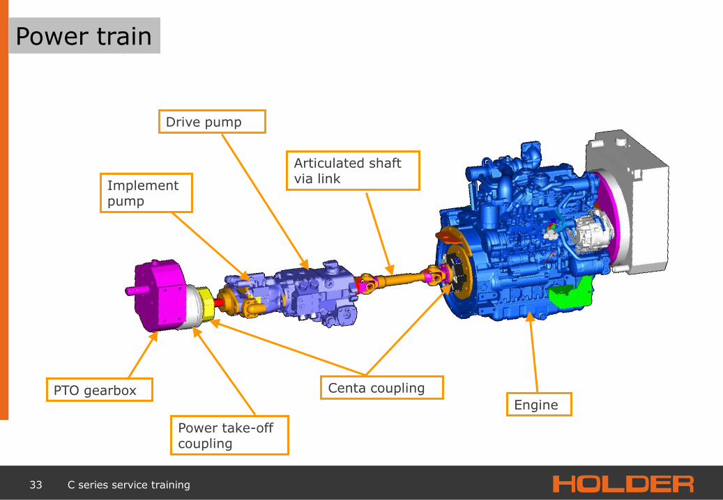
Power train
Drive pump
Articulated shaft via link
Engine
Implement pump
Power take-off coupling
PTO gearbox Centa coupling

34 C series service training
Power train
Centa coupling
Drive pump
Articulated shaft via link

35 C series service training
Power train
Modular structure of the power train
•Single pump
•Tandem pump
•Single pump •Implement pump
•Single pump •Implement pump •Front PTO shaft
•Tandem pump •Front PTO shaft
•Single pump •Front PTO shaft

36 C series service training
Power train

37 C series service training
Power train
Installation of front PTO shaft, alignment of drive pump

38 C series service training
1 General
2 Body/steering
4
Drive train 3
Engine
5 Hub motor/brake
6 Driving hydraulics
C series service training
Working hydraulics
Electrics
Maintenance
Trouble shooting on the vehicle
7
8
9
10

39 C series service training
Engine
The naturally aspirated version
50 HP
4 valves
Direct injected
Prepared for exhaust level IIIb or TIER 4
Cooling air intake only from above
The turbo version
67 HP
4 valves
Direct injected
Prepared for exhaust level TIER 4
Cooling air intake only from above
Kubota V 2607

40 C series service training
Engine
Starter motor
Injection pump Generator
Oil filter
EGR valve
Shutdown solenoid
Fuel filter
Engine

41 C series service training
Engine Trouble shooting
Symptom Possible cause Solution
Engine does not start
No fuel Add fuel
Air in fuel system Vent
Water in fuel system Change fuel and repair or replace fuel system
Fuel line clogged Clean or replace
Fuel filter clogged Replace
Excessively high viscosity of fuel or motor oil at low temperature
Use specified fuel or motor oil
Fuel with low cetane number Use specified fuel
Fuel spot due to loose cap nuts at the injector intake Tighten cap nuts
Incorrect injection point Adjust
Close fuel camshaft Replace
Injector nozzle clogged Repair or replace
Malfunction of injector pump Repair or replace
Crankshaft, camshaft, piston, cylinder or bearing frozen Repair or replace
Loss of compression at cylinder Replace cylinder head gasket, retighten cylinder head bolts and nozzle holder
Incorrect valve control Correct or replace steering wheel
Piston ring and cylinder lock Replace
Incorrect valve clearance Adjust
Malfunction of shutdown solenoid Replace
Starter does not turn
Battery is discharged Charge
Malfunction of starting Repair or replace
Malfunction of key switch Replace
Lines disconnected Reconnect
Engine

42 C series service training
Engine Trouble shooting
Symptom Possible cause Solution
Engine runs roughly
Fuel filter clogged or dirty Replace
Air filter clogged Clean or replace
Fuel spot due to loose cap nuts at the injector intake Tighten lock nuts
Malfunction of injector pump Repair or replace
Incorrect nozzle injection pressure Repair or replace
Injector nozzle locked or is clogged Repair or replace
Malfunction of controller Repair
Turbocharger shaft defective Replace turbocharger assembly
Turbo charger shaft warped Replace turbocharger assembly
Turbocharger blade or other part damaged by foreign body
Replace turbocharger assembly
Exhaust is either white or blue
Too much motor oil Reduce to the specified level
Piston ring and cylinder worn or sticking Repair or replace
Incorrect injection point Adjust
Oil is leaking into the tail or intake pipe
Turbocharger excess oil -pipe clogged or deformed Repair or replace
Turbocharger piston ring seal defective Replace turbocharger assembly
Exhaust is either black or dark grey
Overload Reduce load
Poor-quality fuel used Use specified fuel
Fuel filter clogged Replace
Air filter clogged Clean or replace
Defective injector nozzle Repair or replace nozzle
Engine
43 C series service training
Engine Trouble shooting
Symptom Possible cause Solution
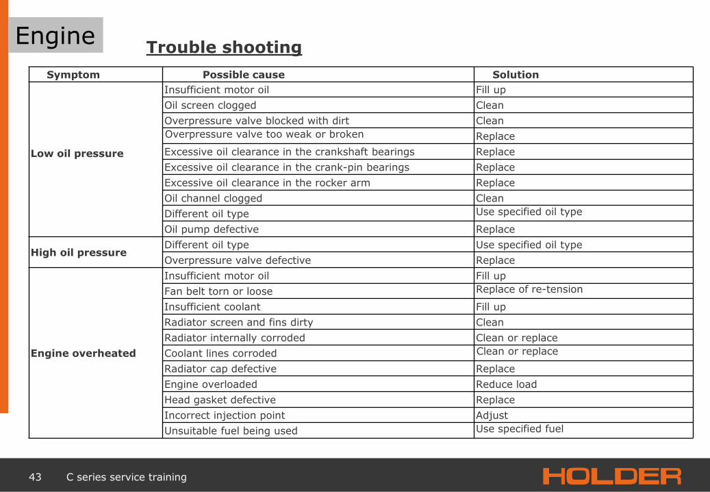
Low oil pressure
Insufficient motor oil Fill up
Oil screen clogged Clean
Overpressure valve blocked with dirt Clean
Overpressure valve too weak or broken Replace
Excessive oil clearance in the crankshaft bearings Replace
Excessive oil clearance in the crank-pin bearings Replace
Excessive oil clearance in the rocker arm Replace
Oil channel clogged Clean
Different oil type Use specified oil type
Oil pump defective Replace
High oil pressure Different oil type Use specified oil type
Overpressure valve defective Replace
Engine overheated
Insufficient motor oil Fill up
Fan belt torn or loose Replace of re-tension
Insufficient coolant Fill up
Radiator screen and fins dirty Clean
Radiator internally corroded Clean or replace
Coolant lines corroded Clean or replace
Radiator cap defective Replace
Engine overloaded Reduce load
Head gasket defective Replace
Incorrect injection point Adjust
Unsuitable fuel being used Use specified fuel
Engine

44 C series service training
Engine Trouble shooting
Symptom Possible cause Solution
Rapid draining of battery
Too little battery acid Refill distilled water and charge
Fan belt slipping Adjust belt tension or replace belt
Lines disconnected Close
Rectifier defective Replace
Generator defective Replace
Battery defective Replace
Engine

45 C series service training
Engine Trouble shooting
Symptom Possible cause Solution
Insufficient engine power
Incorrect injection point Adjust
The movable parts of the engine seem to be frozen
Repair or replace
Malfunction of injector pump Repair or replace
Defective injector nozzle Repair or replace nozzle
Loss of compression Replace head gasket, retighten cylinder head bolts and nozzle holder
Gas leak in the exhaust system Repair or replace
Air leak on the output side of the compressor Repair or replace
Air filter dirty or clogged Repair or replace
Compressor wheel turns hard Replace turbocharger assembly
Excessive lubricating oil consumption
Piston ring gaps pointing in the same direction Realign the end gaps
Oil control ring worn or frozen Replace
Piston ring groove worn Replace piston
Valve stem and valve guide worn Replace
Crankshaft bearings and crank-pin bearings worn
Replace
Oil escaping due to defective gaskets or shaft seals
Replace
Fuel mixed with lubricating oil
Pistons of the injector pump worn Repair or replace
Defective injector nozzle Repair or replace nozzle
Injector pump defective Replace
Water in lubricating oil Head gasket defective Replace
Cylinder block or cylinder head cracked Replace
Engine

46 C series service training
Engine Test and wear values
Part Factory specification Permissible limit value
Compression pressure 32.0 bar/ 250 min-1 (rpm) 22.0 bar/ 250 min-1 (rpm)
Deviation between the cylinders — 10% or less
Valve clearance (cold) 0.13 to 0.17 mm —
Gap 0.60 to 0.80 mm —
Cylinder head surface area Flatness — 0.05 mm
Valve inset clearance (intake and exhaust) 0.65 to 0.85 mm 1.20 mm
Valve stem to valve guide (intake) Clearance 0.030 to 0.057 mm 0.10 mm
Valve stem Outside diameter 5.968 to 5.980 mm -
Valve guide Inside diameter 6.010 to 6.025 mm -
Valve stem to valve guide (exhaust) Clearance 0.045 to 0.072 mm 0.10 mm
Valve stem Outside diameter 5.953 to 5.965 mm -
Valve guide Inside diameter 6.010 to 6.025 mm -
Engine

47 C series service training
Engine Tightening torque
To tighten the screws, bolts and nuts to the specified torque, use a torque spanner. Tighten the screws, bolts and nuts used on the cylinder head, for example, in the correct order and with the correct torque. TIGHTENING TORQUES OF SCREWS, BOLTS AND NUTS FOR GENERAL PURPOSES If no tightening torque is specified, see the table below for unspecified torque values.
Information on screw head
No information or 4T 7T
Information on top of nut
No information or 4T
Unit N m Kgf m Foot-pound Nm Kgf m Foot-pound
M6 7.9 to 9.3 0.80 to 0.95 5.8 to 6.8 9.81 to 11.2 1.00 to 1.15 7.24 to 8.31
M8 18 to 20 1.8 to 2.1 13 to 15 24 to 27 2.4 to 2.8 18 to 20
M10 40 to 45 4.0 to 4.6 29 to 33 49 to 55 5.0 to 5.7 37 to 41
M12 63 to 72 6.4 to 7.4 47 to 53 73 to 90 7.9 to 9.2 58 to 66
Engine

48 C series service training
Engine Tightening torques
Part Size x pitch N m
Glow plug mounting nut M4 x 0.7 0.98 to 1.7
Glow plug M8 x 1.0 7.7 to 9.3
Valve cover screws M6 X 1.0 9.81 to 11.2
Injection line cap nut M12 x 1.5 23 to 36
Oil pressure switch R 1/8 15 to 19
Injection pump mounting flange nut M8 x 1.25 10 to 20
Drain plug M22 x 1.5 45 to 53
Mounting screw for oil line 1 M10 x 1.25 16 to 19
Thermal valve R3/S 30 to 39
Injection nozzle holder screw M8 x 1.25 24 to 27
Holding screw for overflow line unit M6 x 1.0 9.01 to 11.2
* Mounting screw for lubricating oil line M10 x 1.25 16 to 19
Mounting screw for regulator housing M6 x 1.0 9.81 to 11.2
Lock nut M5 x 0.8 2.9 to 4.0
NOTE •For the screws and nuts marked with a "*" in the table, motor oil must be applied to the screw and nut seat before tightening. •The letter "M" in the "Size and pitch" column indicates that the screw or nut dimension is a metric dimension. The size is the nominal outside diameter of the threads in mm. The pitch is the distance in mm between two threads.
Engine

49 C series service training
Engine Tightening torques
Part Size x pitch N m
Mounting screw for injection pump assembly M6 x 1.25 24 to 27
Mounting nut for injection pump assembly M8 x 1.25 10 to 20
Regulator weight mounting nut M12 x 1.25 63 to 72
Injection pump shaft stop M6 x 1.0 9.81 to 11.2
Mounting screw for the fuel control shaft bearing cover M6 x 1.0 3.9 to 4.2
* Crankshaft bolt M16 x 1.5 255 to 274
Overpressure valve screw M22 x 1.5 69 to 78
* Flywheel bolt M12 x 1.25 98.1 to 107
Camshaft bolt M8 x 1.25 24 to 27
Balance shaft screw M8 x 1.25 24 to 27
Starter terminal B mounting nut M8 x 1.25 9.0 to 11
Nut for generator belt pulley M24 50.4 to 78.9
Oil pump cover screws M6 7.0 to 9.3
NOTE •For the screws and nuts marked with a "*" in the table, motor oil must be applied to the screw and nut seat before tightening. •The letter "M" in the "Size and pitch" column indicates that the screw or nut dimension is a metric dimension. The size is the nominal outside diameter of the threads in mm. The pitch is the distance in mm between two threads.
Engine

50 C series service training
Engine Tightening torques
Part Size x pitch Nm
Rocker arm bracket screw M8 x 1.25 24 to 27
* Cylinder head screw M13 x 1.25 147 to 156
Mounting nut for injection pump gear (left-hand thread) M16 x 1.5 LH 93.2 to 102
Oil cooler connection screw M20 x 1.5 64 to 73
Mounting screw for front cover M6 x 1.25 24 to 27
Mounting screw for flywheel housing M12 x 1.25 73 to 90
Mounting screw for intermediate gear M10 x 1.25 49 to 55
* Connecting rod screw [Serial number: 8G0o01 to 9K9999] M8 x 1.0 45 to 49
* Connecting rod screw [Serial number: 9L0001 and above] M8 x 1.0 41 to 45
* Mounting screws, conductor frame 2 M13 x 1.25 123 to 137
Collar screws of crankcase 2 M10 x 1.25 49 to 55
NOTE •For the screws and nuts marked with "*" in the table, motor oil must be applied to the screw and nut seat before tightening. •The letter "M" in the "Size and pitch" column indicates that the screw or nut dimension is a metric dimension. The size is the nominal outside diameter of the threads in mm. The pitch is the distance in mm between two threads.
Engine

51 C series service training
Engine Checking compression pressure
Compression pressure Factory specification 32.0 bar/250 min-1
(rpm)
Permissible limit value
22.0 bar / 250 min-1
(rpm)
Tightening torque Glow plug mounting nut
0.98 to 1.7 Nm
Glow plug 7.7 to 9.3 N m
(1) Compression tester (2) Glow plug adapter
1. Turn off the engine after it has warmed up and remove the air filter, the muffler, the venting pipe, the glow plug line and glow plugs. 2. Mount a compression tester (1) (Part No. : 07000-30208) glow plug adapter (2) (for the diesel engines V2607 or V3007 / V3307) at the glow plug hole. 3. After making sure that the speed control lever is in the stop position (no injection), turn the engine with the starter motor at 200 to 300 min1 (rpm). 4. Read off the maximum pressures and measure more than twice.
■ NOTE
• Check compression pressure with properly adjusted valve clearance • Always use a fully charged battery for the compression pressure check. • The deviation between the individual values may not be more than 10%.
Engine

52 C series service training
Engine Adjusting valve clearance
■ IMPORTANT ■ The valve clearance must be checked and adjusted when the engine is cold. 1. Remove the high-pressure pipe, the glow plug lines, the glow plugs and the valve cover. 2. Align the OT marking 1TC on the flywheel in the timing wheel at the top of the flywheel housing so that the first piston (front cover side) is at the compression top dead centre point. 3. Loosen the lock nut (4) of setscrew (3) : (push rod side) and push the feeler gauge between the rocker arm and the head of the rocker arm bridge. Adjust the setscrew (3) to the specified value and then tighten the lock nut. Valve clearance A Factory specification 0.13 to 0.17 mm
■ NOTE
Tighten the lock nut (4) firmly after the adjustment. Valve arrangement
Cylinder to be adjusted Piston position
INTAKE EXHAUST
When piston No. 1 is at compression top dead centre.
1 *
2.
3.
4.
When piston No. 1 is in the overlapping position.
1
2.
3. *
4.
Tightening torque Valve cover screw 9.81 to 11.2 Nm
Injection line
retaining nut
23 to 36 Nm
(1) Setscrew A : Valve clearance (2) Lock nut (3) Setscrew (4) Lock nut
Engine

53 C series service training
Engine Checking oil pressure
1. Remove the engine oil pressure switch and install a measuring adapter (Part No. 07916-32032). 2. Start the engine. After the operating temperature has been reached measure the oil pressure at idling speed and at nominal speed. 3. If the oil pressure is below the permissible limit value, the following causes are possible: •Oil level too low •Oil pump defective •Oil screen clogged •Oil filter cartridge clogged •Oil gallery clogged •Excessively large oil gap crankshaft bearings •Foreign body in the overpressure valve (During assembly) - After the engine oil pressure has been checked, retighten the engine oil pressure switch at the specified torque.
Engine oil
pressure
At idling speed
Permissible limit value 0.49 bar
At nominal speed
Factory specification 1.97 to 3.92 bar
Permissible limit value 1.47 bar
Tightening torque Oil pressure switch 14 to 19 n m
Engine

54 C series service training
Engine Checking fan belt
Belt tension
Wear and damage
1. Measure the deflection (A); to do this, press the V-belt (2) between the camshaft pulley and the alternator pulley with the specified force of 98 N. 2. If the measured value does not match the factory specification, loosen the generator mounting screws and adjust the belt tension by moving the generator. Then retighten the mounting screws (1).
Deflection (A) Factory specification 10.0 to 12.0 mm
(1) Mounting screws (A) Deflection (2) V-belt
1. Check the V-belt for damage. 2. If the V-belt is damaged, replace it. 3. Check whether the V-belt is worn or rides too deeply in the belt pulley groove. 4. If the V-belt is nearly worn out or rides to deeply in the belt pulley groove, replace the V-belt. (A) Correct (B) Incorrect
Engine

55 C series service training
Engine
Integrity of the radiator cap
Checking radiator cap
1. Connect a radiator testing device (1) and an adapter (2) to the radiator cap. 2. Subject the radiator cap to a pressure of 88 kPa (0.88 bar, 13 psi) and measure the time until the pressure falls to 59 kPa (0.59 bar, 8.5 psi). 3. If the measured value is below factory specifications, replace the radiator cap.
Permissible pressure
drop
Factory specification More than 10 sec for a pressure drop fro 0.88 to 0.59 bar.
(1) Radiator testing device (2) Adapter
ATTENTION: * When the radiator cap is removed, wait at least ten minutes after eh engine has been shut off ad cooled down. Otherwise, hot water will squirt out, which can scald bystanders.
Engine

56 C series service training
Engine Checking coolant thermostat
1. Press the thermostat valve down and clamp a thread between valve and valve seat. 2. Place the thermostat and a thermometer in a container with water and gradually heat up the water. 3. Hold the thermostat suspended from the thread in the water. When the water temperature rises, the thermostat will open and fall off the thread. Measure the temperature at this moment with the thermometer. 4. Further heat the water and read the temperature when the valve has opened by approx. 8 mm. 5. If the measured value is not within factory specifications, replace the thermostat.
Thermostat valve
opening
temperature
V2607-DI-T-E3B Factory specification
80 to 84°C
Temperature at
which the thermostat
V2607-DI-T-E3B Factory specification
95°C 203°F
opens completely
Engine

57 C series service training
Engine Adjusting start of pumping
1. Ensure that the injection time markings (1) on the injector pump and on the flywheel housing agree, as shown in the figure. 2. Remove the injection lines. 3. Remove shutdown solenoid. 4. Slowly turn the flywheel counter-clockwise (as viewed onto the flywheel), until the fuel reaches up to the opening of the pressure valve holder (3) for the first cylinder. 5. Once the fuel reaches as far as the opening of the pressure valve holder (3) of the first cylinder, turn the flywheel back clockwise by 1.6 rad (90°). 6. Now turn the flywheel counter-clockwise up to about 0.17 rad (10°) before TDC. 7. Continue turning the flywheel slowly counter-clockwise and only stop turning when fuel begins to rise, in order to determine current start of pumping. 8. Check the number of degrees on the flywheel. The flywheel has the markings "1TC" for the crank angle before top dead centre (TDC) of piston 1. 9. If the start of pumping is not within specification, turn the injector pump to adjust the start of pumping.
Tightening torque
Cap nut Injection line
23 to 36 N m
Injection pumps Mounting flange nuts
18 to 20 N m
Model: Factory specification
V2607-DI-T-E3B (serial
number:
8G001 to 8V9999)
0,0087 rad before TDC to 0.017 rad after TDC (0.50 ° before
TDC to 1.0 ° after TDC)
V2607-DI-T-E3B (serial
number: 8W0001 and above]
0.0017 rad before TDC to 0.0087 rad after TDC (1.0° before
TDC to 0.50° after TDC)
(1) Injection time markings (2) Injector pump mounting flange nuts (3) Pressure valve holder
(A) Early injection time (b) Late injection time
IMPORTANT If the injector pump is mounted on the engine block, maintain the proper procedure. See "Injector pump unit".
Engine

58 C series service training
Engine Checking pump element
1. Remove shutdown solenoid. 2. Remove the injection lines. 3. Mount the injection pump pressure testing device (1) on the injector pump. 4. Mount an injection nozzle (2) that is set to factory specifications on the second connection of the injection pump pressure testing device (1). (See figure) 5. Set the speed control lever to the maximum rotational speed. 6. Actuate the starter to rotate the engine. 7. If the pressure cannot reach the permissible limit value, replace the pump or have it repaired in a shop authorised by Kubota.
Fuel tightness of the pump element
Permissible limit
value
196.3 bar
NOTE
Never attempt to disassemble the injector pump. Have repairs done only in a shop authorised by Kubota.
(1)Injector pump pressure testing device (2)Injection nozzle
(3) Protective cover for escaping fuel
Engine

59 C series service training
Engine Checking down-valve
1. Remove shutdown solenoid. 2. Remove the injection lines. 3. Mount the injection pump pressure testing device on the injector pump. 4. Mount an injection nozzle (2) that is set to factory specifications on the second connection of the injection pump pressure testing device (1). 5. Actuate the starter to raise the pressure. Switch off the starter when the fuel escapes from the injection nozzle (2). 6. Then turn the flywheel by hand and raise the pressure to approx. 186.3 bar. 7. Turn the flywheel back by approx, half a revolution and hold the flywheel in position. Leave the flywheel in this position and determine the time that passes for a pressure drop from 186.3 to 176.5 bar. 8. Measure the time until the pressure drops from 186.3 to 176.5 bar. 9. If the the measured value is below the permissible limit value, replace the pump or have it repaired in a shop authorised by Kubota.
Fuel-tightness of the
down-valve
Factory specification 10 seconds
186. – 176. bar
Permissible limit value 5 seconds
186.3– 176.5 bar
Note Never disassemble the injector pump. Have repairs done only in a shop authorised by Kubota. (1)Injector pump pressure testing device (2) Injection nozzle (3) Protective cover for escaping fuel
Engine

60 C series service training
Engine
Checking nozzle spray pattern
Checking injection pressure
Checking injection nozzle
1. Mount the injection nozzle on a nozzle testing device and check the spray pattern. 2. If the spray pattern does not match the factory specifications, the injection nozzle assembly must be replaced or repaired in a repair shop approved by Denso. (a) Correct (b) Incorrect
1. Insert the injection nozzle into the nozzle tester. 2. Slowly turn the test device handle in order to measure the pressure at which the fuel begins to escape from the nozzle. 3. If the measured value does not match the factory specifications, the injection nozzle assembly must be replaced or repaired in a repair shop approved by Denso.
NOTE The injection nozzle seal must be replaced when the injection nozzle is dismantled for testing.
Injection pressure
(Phase 1)
Factory
specification
18.64 to 20.10 MPa
V2607-DI-T-E3B 186.4 to 201.0 bar
2703 to 2915 psi
ATTENTION: • Check the injection pressure and the spray pattern after having previously ensured that no one is in the spray direction of the atomised fluid. • If the human body comes into direct contact with the mist, cells can be damaged and blood poisoning can occur.
Engine

61 C series service training
Engine
Checking valve seat tightness
Checking valve seat
1. Insert the injection nozzle into the nozzle tester. 2. Raise the fuel pressure and hold it for 10 seconds at 16.67 MPa (166.7 bar, 2416 psi). 3. If spot of fuel is found, the injection nozzle assembly must be replaced or repaired in a repair shop approved by Denso.
Valve seat tightness
Factory specification
No fuel leakage
166.7 bar
Engine

62 C series service training
Engine Checking starter
■ NOTE
• Terminal B : The terminal at which the cable from the battery is connected to the starter. • Terminal C : The terminal at which the cable from the engine is connected to the solenoid.
1. Disconnect the earth wire from the battery. 2. Disconnect the positive cable from the battery. 3. Remove the connection cable fromterminal B of the
starter. 4. Remove the starter. 5. Connect a bridge cable between the starter terminal C (1)
and the positive battery pole (2). 6. Briefly connect a bridge cable between the starter housing
and the negative pole (3) of the battery. 7. If the engine does not run, the starter is defective. Repair
or replace the starter.
ATTENTION: * Fasten the starter to prevent it from tearing loose during the test.
(1) Terminal C (3) Negative pole (2) Positive pole
Engine

63 C series service training
Engine Checking solenoid
Checking continuity
■ NOTE
Terminal B : The terminal at which the cable from the battery is connected to the starter. Terminal S: The terminal at which the cable from the starter switch is connected to the solenoid.
1. Disconnect the earth wire from the battery. 2. Disconnect the positive cable from the
battery. 3. Remove the connection cable from terminal B
of the starter. 4. Remove the starter. 5. Connect a bridge cable between the starter
terminal S (1) and the positive battery pole (2).
6. Briefly connect a bridge cable between the starter housing and the negative pole (3) of the battery.
7. If the pinion does jump out, the solenoid is defective. Repair or replace the starter.
1. Test for continuity between terminal C (1) and terminal B (2) with a circuit tester while simultaneously depressing the pin.
2. If there is no continuity or if a certain value is displayed, replace the solenoid.
(1) Terminal S (3) Negative pole (2) Positive pole
(1) Terminal C (2) Terminal B
Engine

64 C series service training
Engine Checking the generator
■ NOTE
• Take care that rotating parts are no touched during the test. Maintain a safety margin from rotating parts.
(Before testing) • Before testing the generator, check the battery terminals, circuit connections, fan belt tension, charge indicator lamp, as well as the fuses in the circuit. • Use a charged battery for the test.
1. Start the engine. 2. With the engine running, measure the voltage
between the battery poles. If the voltage is between 13.8 V and 14.3 V, the generator is operating normally.
3. If the results of the generator test are not within specification, check each component in order to locate the fault. See "DISMANTLING AND ASSEMBLING" and "MAINTENANCE" of the generator.
Standard voltage without
load
Factory specification 13.8 to 14.8 V at 25°C (77°F)
Engine

65 C series service training
Engine Checking glow plug
NOTE Orient the depression to the connection side when seal (1) is mounted on glow plug (2).
1. Remove the glow plug (2). 2. Check the resistance between the glow plug
connector and the glow plug housing with an ohmmeter.
3. If the factory specification is not achieved, the glow plug (2) is defective.
Resistance Factory specification Roughly 0.95
(1) Seal (2) Glow plug
Engine

66 C series service training
Engine Checking shutdown solenoid
1. Remove shutdown solenoid. 2. Connect the bridge lines between the contact for
the pull winding P and switch (3), and between switch (3) and the positive battery pole.
3. Connect the bridge lines between the contact for the holding winding K and switch (4), and between switch (4) and the positive battery pole.
4. Connect bridge line between the body of the engine shutdown solenoid and the negative battery pole.
5. If switch (4) is turned on, the pin is attracted and the armature comes back out if switch (4) is turned off.
6. First turn on switch (3) and then switch (4) - the pin will be drawn into the magnet body and remains in this position when switch (4) is turned off.
7. If the pin is not attracted,, the engine shutdown solenoid is defective.
IMPORTANT During the inspection, never apply power for longer than two seconds to the pulling coil.
(1) Plug connector P: pull winding terminal (2) Battery H: holding winding terminal (2) Switch for the holding coil (4) Switch for the pulling coil
Engine

67 C series service training
Engine Checking turbocharger
Turbine-side
Compressor-side
Radial clearance
1. Check the exhaust side (2) and the intake side (4) of the turbine housing (3) for escaping exhaust gas. 2. If a gas leak is found, tighten the screws and nuts or replace the seal (1)/(5) with a new part.
1. Check the intake hose (4) of the compressor housing (1) for leakage. 2. Check for loose connections or tears on the suction side (3) of the air intake pipe. 3. If a leak is found, replace the hose clip (2) and/or the intake hoses (3)
1. If the turbine or compressor impeller comes into contact with the housing, replace the turbocharger unit with a new one.
(1) Seal (4) Intake (2)Exhaust (5) Seal (3) Turbine housing
(1) Compressor housing (3) Intake hose (2) Clip (4) Exhaust hose
Engine
68 C series service training
Engine Checking EGR system
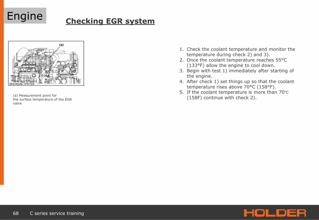
1. Check the coolant temperature and monitor the temperature during check 2) and 3).
2. Once the coolant temperature reaches 55°C (133°F) allow the engine to cool down.
3. Begin with test 1) immediately after starting of the engine.
4. After check 1) set things up so that the coolant temperature rises above 70°C (158°F).
5. If the coolant temperature is more than 70℃
(158F) continue with check 2). (a) Measurement point for the surface temperature of the EGR valve
Engine

69 C series service training
Engine Checking EGR system
If the coolant temperature is below 55°C (131°F), the surface temperature of the EGR valve must be below 100°C (212°F).
Below 100°C (212°F)
The EGR system is OK
The surface temperature falls
Thermal valve defective
Is the surface temperature of the EGR valve above 100 °C (212°F) with a coolant temperature below 55°C (131°F)?
Above 100°C (212 °F)
Disconnect the turbo pressure hose from the EGR valve.
Measure the surface temperature of the EGR valve
The surface temperature is still above 100°C (212°F)
EGR valve is defective
Engine

70 C series service training
Engine Checking EGR system
2) If the coolant temperature is above 70 ℃ (131°F), the surface temperature of the EGR valve
must be above 100°C (212°F).
Is the surface temperature of the EGR valve above 100℃ (212°F) with a coolant temperature above 70℃ (158F)?
Below 100°C (212°F) Above 100°C (212 °F)
The EGR system is OK Connect the hose directly between the intake distributor flange and the EGR valve.
Measure the surface temperature of the EGR valve
The surface temperature rises
Thermal valve defective
The surface temperature is still below 100°C (212°F)
EGR valve is defective
Engine

71 C series service training
Engine
Air
Air taken in for engine from above
→ Polluted air behind the vehicle
is not taken in
Air intake Engine

72 C series service training
1 General
2 Frame / steering
4
Power train 3
Engine
5 Wheelmotor / brake
6 Drive hydraulics
Service
Working hydraulics
Electrics
Maintenance
Trouble shooting on the vehicle
7
8
9
10

73 C series service training
Wheelmotor
MCR 3N wheelmotor
Cross-sectional view

74 C series service training
Hub motor
Pressure applied
Depressurised
Cross-sectional view of the power unit for a wheelmotor
Mode of operation
Wheelmotor

75 C series service training
Hub motor
Differential lock housing
Differential lock selector shaft
Connecting tube
Brake drums
Wheelmotor

76 C series service training
Brakes
Adjuster
Brake shoe
Slave cylinder

77 C series service training
Brakes
Master cylinder
Pressure switch for brake light
Brake fluid supply reservoir
Service brakes

78 C series service training
Brakes
Electric servomotor
Pull cable for parking brake
Parking brake

79 C series service training
1 General
2 Frame / steering
4
Power train 3
Engine
5 Wheelmotor / brake
6 Drive hydraulics
Service
Working hydraulics
Electrics
Maintenance
Trouble shooting on the vehicle
7
8
9
10

80 C series service training
Driving hydraulics
Trouble shooting
Vehicle electronics in general Faults in vehicle electronics Fault lamp lights up or flashes if the following conditions are met: - Ignition on - Drive program switch set to 1, 2, 3 or 4 - Direction switch is set to Neutral.
Read Bodem fault memory 1) Remedy fault 1) Delete fault in fault memory1)
No forward and repair 1) backward travel Direction switch set to Neutral Set direction switch to desired direction
Machine started with preselected direction Set direction switch to neutral and preselect desired direction
No power supply for the electronics Check fuses
Electrical connection to servopump interrupted Check electrical connection Restore connection 1)
Direction switch defective or poor contact Replace direction switch Restore contact 1)
Drive programme switch set to 0 Select desired drive programme
Fast-slow cannot be switched Drive programme switch defective Hydraulic valve for slow/fast defective or no pressure available
Replace drive programme switch 1)
Check low-pressure valve 1)
Electrical connection to hydraulic valve for fast/slow interrupted, or bad contact
Restore connection 1)

81 C series service training
Driving hydraulics
Trouble shooting
Not enough traction Fault in supply or high-pressure system Check return suction filter 1) Check hydraulic system supply pressure Check high-pressure hydraulic system 1) Check leakage on servopumps and wheel motors 1)
Check control devices and proportional magnets of the servopumps 1)
Check maximum current on proportional magnets 1)
No forward and backward travel or only one
direction
Fault in supply or high-pressure system Check hydraulic system supply pressure 1) Check high-pressure hydraulic system 1) Check control devices and proportional magnets
of the servopumps
Only one direction of travel Direction switch defective Electrical connection to servopump interrupted
Replace direction switch Restore connection
Driving hydraulics

82 C series service training
Driving hydraulics
Technical Data
•Main circuit 28 cm3
•Supply pump 15.1 cm3
•Rotational speed 2700 rpm
Drive pump
Control unit
Supply pump
Driving hydraulics

83 C series service training
Driving hydraulics Holder
MeGu bearing
Drive pump
Driving hydraulics

84 C series service training
Driving hydraulics
Drive pump
Front axle
Rear axle
High-pressure system
Driving hydraulics
85 C series service training
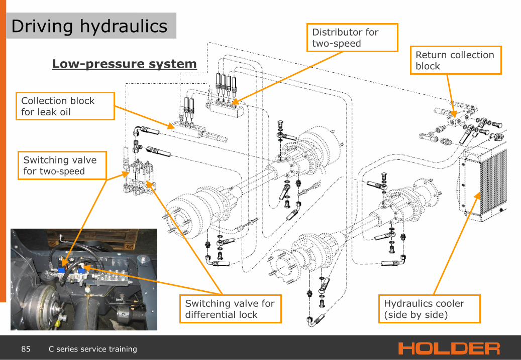
Driving hydraulics
Low-pressure system
Collection block for leak oil
Switching valve for differential lock
Switching valve for two-speed
Distributor for two-speed
Return collection block
Hydraulics cooler (side by side)
Driving hydraulics

86 C series service training
1 General
2 Frame / steering
4
Power train 3
Engine
5 Wheelmotor / brake
6 Drive hydraulics
Service
Working hydraulics
Electrics
Maintenance
Trouble shooting on the vehicle
7
8
9
10

87 C series service training
Working hydraulics
Multiway valve
Cartridge for independent floating position
Priority valve
Pilot control valve Working hydraulics

88 C series service training
Working hydraulics
Pilot control valve SA switching valve
Priority valve DA switching valve Flow divider, circuit 1
Module for independent floating position
Working hydraulics

89 C series service training
Working hydraulics
Hydraulic block schematic
Power regulator for motor operation
Priority
valv
e f
or
ste
ering
Pro
p.
pilot
contr
ol
valv
e
Module
-indep.
floating p
ositio
n f
or
double
-acting m
ode,
flanged o
nto
2/2
way v
alv
e (
double
-acting)
or
separa
tely
mounte
d
Exis
ting 2
/2 m
odule
(double
-acting )
as s
ingle
-acting v
alv
e
with e
xt.
tank lin
e
Module
-indep.
floating p
ositio
n f
or
sin
gle
-acting m
ode,
flanged o
nto
2/2
way v
alv
e (
double
-acting)
or
separa
tely
mounte
d
2/2
way v
alv
e (
double
-acting)
norm
al m
odule
Working hydraulics

90 C series service training
Working hydraulics
Connection plate
Hydraulic tank
Valve block for working hydraulics
Working hydraulics measuring connection
Hydraulic pump for working hydraulics and steering
Steering servo
Oil circulation
Working hydraulics

91 C series service training
Working hydraulics Working hydraulics

92 C series service training
Working hydraulics Working hydraulics

93 C series service training
Working hydraulics
Functions of the front lift
Function Operation Symptom Example Photograph/symbol/ remark
1. Lifting/lowering Joystick forwards/backwards
Lift and front unit raises and lower themselves proportionally to the joystick movement and correspondingly fast raised unit automatically pressed horizontal at the top selected floating position is deactivated.
Raising or lowering of a front implement, e.g., hedge clippers
2. Lifting Pull joystick back
Lift raises itself Hydro reservoir fills itself time-offset
Front implement spontaneously rises without delay, important, e.g., when facing obstacles while ploughing snow
3. Driving with raised implement
No operation necessary
Hydro reservoir damps vibrations Driving mode Implement acts as a damping mass on the vehicle
Suspension properties with implement better than without
4. Single-acting setting
Toggle switch under arm rest
EW: Implement cannot be actively pressed, can passively evade upwards
EW: Mower cannot be loaded by the machine.
5. Double-acting setting
Toggle switch under arm rest
DW: active operation in both directions
DW: Snow plough can be pressed downwards
6. Floating position Button on joystick
Lift and front implement freely movable vertically Is deactivated while lifting Indicator lamp on operating console
Necessary if ground adaptation of the implement is desired
Working hydraulics

94 C series service training
Working hydraulics
Functions of the front lift
7. Transverse inclination "OFF“
Shut-off switch under arm rest
Transverse direction of the front lift (in the longitudinal axis) is preserved (lifter transversely rigid)
Moving on inclines Cutting through hard snow
8. Transverse inclination "ON“
Mode switch under arm rest
Lift freely movable transversely (floats)
Implement is intended to adapt to the ground in connection with implement relief
9. Transverse inclination „AUTO“
Mode switch under arm rest
Lift is freely movable as soon as floating position for "lowering" is activated Is automatically deactivated when lifting
Optimal for many devices: floating position vertically and transversely automatic for optimal adaptation to the ground and easy operation
10. Active transverse
inclination adjustment (option)
Toggle switch on operating console or joystick
Lift is actively adjusted transversely Speed adjustable via potentiometer Mode switch "Transverse" to "Off"
Snow cutter can be actively adjusted transversely to produce a horizontal base
11. Active lateral adjustment (option)
Toggle switch on operating console or joystick
Lift is actively adjusted laterally (about vertical axis)
Implement can be displaced somewhat laterally or steered in the curve
12. Hydraulic implement relief (option)
Switch on operating console Pressure setting on B-pillar at right Floating position "Off" must be "On"
Front implement is "carried" with set pressure in the front left, so that it lies with less weight on the ground. Amount of relief adjustable via pressure gauge Indicator lamp on operating console Is deactivated when lifting
Mower: easier guidance of the implement, better traction and steering ability of the vehicle Snow plough see above
Working hydraulics

95 C series service training
Working hydraulics
Valve block for working hydraulics
Cylinder for hydraulic tipping system
Tipping system
Working hydraulics

96 C series service training
Cardan shaft for mechanical Side adjustment
for front lift
Lower link frame
Cylinder for front lift
Front lift
Catch hook
Working hydraulics Working hydraulics

97 C series service training
Working hydraulics Pressure accumulator
Valve for inclination adjustment
Fast lift valve
Switching valve for differential lock
Front lift
Hydraulic cylinder
Collection block for reflux
Pilot control valve
On wheel load balance

98 C series service training
Hydraulics plan for front lift
(1) Priority valve for steering
(2) Input module with pressure scale and prop. pilot control valve
(3) Module-indep. Floating position for single-acting mode, flanged onto 2/2 way valve (double-acting) (4) 2/2 way valve (double-acting) normal module (5) Module-indep. Floating position for double-acting mode, on 2/2 way valve (double-acting)
E. hydr. implement relief
Fast lift valve
Hydr. Stabilizer
Front lift Float position transverse
Active inclination adjustment
Working hydraulics

99 C series service training
1 General
2 Frame / steering
4
Power train 3
Engine
5 Wheelmotor / brake
6 Drive hydraulics
Service
Working hydraulics
Electrics
Maintenance
Trouble shooting on the vehicle
7
8
9
10
100 C series service training
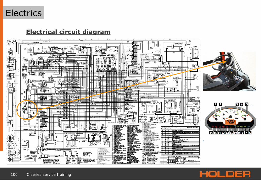
Electrics
Electrical circuit diagram
Electrics

101 C series service training
Electrics
Electrical circuit diagram
Electrics

102 C series service training
Electrics
Electrical circuit diagram
Electrics

103 C series service training
Electrics
Electrical circuit diagram
Electrics

104 C series service training
Electrics
Electrical circuit diagram
Electrics

105 C series service training
Electrics
Electrical circuit diagram
Electrics

106 C series service training
Electrics
PTO shut-off
Electrics
107 C series service training
Electrics
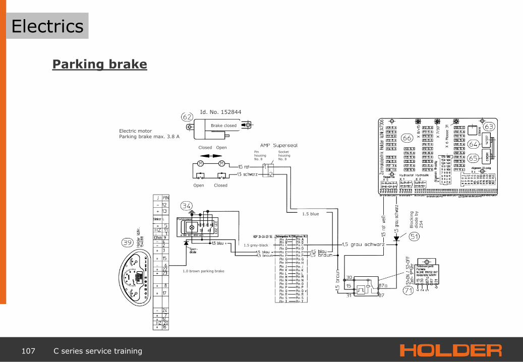
Parking brake
Electric motor Parking brake max. 3.8 A
Brake closed
Closed Open
Open Closed
1.5 blue
1.0 brown parking brake
Id. No. 152844
Pin housing No. 8
Socket housing No. 8
Blo
ckin
g
dio
de b
y
254
1.5 grey-black
Electrics

108 C series service training
Electrics
Fuse assignment
Fuse Maximum current conductor trace
Supply from source
Circuit designation Nominal current of the equipped fuse
Transfer to plug
connector
F01 15 15 Multifunction display Remote thermometer Hydraulic oil 15A -X4.5
F02 15 15 Inductive switch , speed/2-pole Heck socket 15A -X4.3
F03 15 15 Room lamp/interior lamp 15A -X4.5
F04 15 X4.7+8+9 Parking light 58 R 15A X 3.17
F05 15 X4.7+8+9 For multifunction device Remote hydr. thermometer For flashing
warning light switch
15A -X3.13
F06 15 X4.7+8+9 Left parking light 58 L; Label lighting, cab rear 15A -X3.13
F07 15 X4.11 Full beam remote light indicator lamp 15A X 3.9
F08 15 X4.11 Dipped beam light 15A -X3,7
F09 20 15 Front wiper interval 15A not implem.
F10 20 30 Warning light 20A -X3.1/-X3.3
F11 15 30 Radio 30 15A -X3.5
F12 20 15 Air-conditioning system 15A -X4.4/-X4.6
F13 15 15 2-pin socket/electrical seat adjustment 15 15A -X4.2
F14 15 15 Heatable external mirror 10A -X5.4
F15 15 15 Brake light 15A -X3.15
F16 15 15 Blinking signal light/head lamp 0-pos/washer 15A -X3.18
Electrics

109 C series service training
Electrics
Fuse assignment
Fuse Maximum current conductor trace
Supply from source
Circuit designation Nominal current of the equipped fuse
Transfer to plug
connector
F17 15 15 Cigarette lighter Working spotlight, cab rear 15A -X3.16
F18 20 15 Deutz shutdown solenoid 15A -X3.12/-X3.14
F19 20 15 Heater fan 15A -X3 8/-X3.10
F20 15 16 Reserve 15A -X3.5
F21 15 15 Radio 15 15A -X3 4
F22 15 15 Flashing light 15A -X3 2
F23 15 30 Reserved general vehicle electronics 15A -X5.7
F24 15 30 Reserved general vehicle electronics 15A -X5 5
F25 15 15 Seat heater 15A -X5 8
F26 15 15 Reverse key switch/implement pump coding 1A -X5.3
F27 15 15 Reserve 15A -X 5.1
F28 15 15 Bucher electronics PIN34 15A -X5.2
F29 15 15 Diff. lock/2-stage starring/parking brake solenoid 15A -X2.3
F30 15 15 Solenoid valve, PTO shaft back 15A -X2.2
F31 15 15 Solenoid valve, PTO shaft front 15A -X2.1
F32 15 15 Hydraulics solenoid, membrane keypad On-Off 15A -X2.4
F33 15 15 Hydraulics Bucher electronics position 23 15A -X2.5
F34 15 15 Hydraulics Bucher electronics position 05 15A -X2.6
Electrics
110 C series service training
Electrics
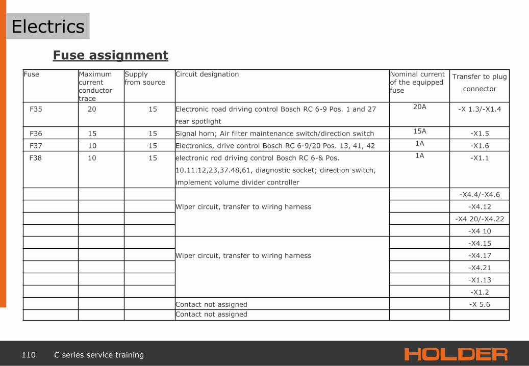
Fuse assignment
Fuse Maximum current conductor trace
Supply from source
Circuit designation Nominal current of the equipped fuse
Transfer to plug
connector
F35 20 15 Electronic road driving control Bosch RC 6-9 Pos. 1 and 27
rear spotlight
20A -X 1.3/-X1.4
F36 15 15 Signal horn; Air filter maintenance switch/direction switch 15A -X1.5
F37 10 15 Electronics, drive control Bosch RC 6-9/20 Pos. 13, 41, 42 1A -X1.6
F38 10 15 electronic rod driving control Bosch RC 6-& Pos.
10.11.12,23,37.48,61, diagnostic socket; direction switch,
implement volume divider controller
1A -X1.1
Wiper circuit, transfer to wiring harness
-X4.4/-X4.6
-X4.12
-X4 20/-X4.22
-X4 10
Wiper circuit, transfer to wiring harness
-X4.15
-X4.17
-X4.21
-X1.13
-X1.2
Contact not assigned -X 5.6
Contact not assigned
Electrics

111 C series service training
Electrics
Circuit diagram for working hydraulics

112 C series service training
1 General
2 Frame / steering
4
Power train 3
Engine
5 Wheelmotor / brake
6 Drive hydraulics
Service
Working hydraulics
Electrics
Maintenance
Trouble shooting on the vehicle
7
8
9
10

113 C series service training
Maintenance
Maintenanceschedule
Maintenance

114 C series service training
Maintenance
Use Supply Specification Season Amount to be filled
Engine (see Kubota operating manual)
Multi-grade motor oil
SAE 5W-40
All-year ACEA E2-36 ; E3-96/E5-02 ;
E4-99/E6-04 incl. filter, 8.5
litres
API CH-4/CG-4: DHD-1
Cooling system Cooler antifreeze and
water ASTMD4985 All-year 3.0 litres
Hydraulic tank Hydraulic oil
HE-oils (hydr. ester) VG46 All-year
Mineral-based hydraulic-oil HVLP per DIN 51524
VG46 Winter 35 litres
VG68 Summer
Fuel tank (see Deutz operating manual)
Diesel fuel
Commercial diesel fuel with a sulphur content below 0.5% All-year
DIN EN 590
Brake system Brake fluid D0T4 All-year 0.4 litres
Air-conditioning system Refrigerant R134 a All-year 850 g
Lubrication nipple Multipurpose grease Penetration number of 260 to 230 All-year as needed
Battery terminals Acid protection
grease Ordinary commercial battery
pole grease All-year as needed
Window wising system Radiator antifreeze
and water
Water + commercial cleaning solution Summer 1.5 litres
Water + commercial cleaning solution with antifreeze properties
Winter 1.5 litres
Paint preservation Preservation wax Ordinary commercial preservation wax Winter [winter
service protection]
as needed
Supplies and lubricants C250, C270

115 C series service training
Thank you for your attention!
Dietmar Fecht Tel: 07123-966 218 Fax: 07123-966 228 E-mail: [email protected]

116 C series service training
1 General
2 Frame / steering
4
Power train 3
Engine
5 Wheelmotor / brake
6 Drive hydraulics
Service
Working hydraulics
Electrics
Maintenance
Trouble shooting on the vehicle
7
8
9
10

117 C series service training
1 General
2 Body/steering
4
Drive train 3
Engine
5 Hub motor/brake
6 Driving hydraulics
C series service training
Working hydraulics
Electrics
Maintenance
Trouble shooting on the vehicle
7
8
9
10

118 C series service training
Trouble shooting on the vehicle
Notes

119 C series service training
Trouble shooting on the vehicle
Notes
Trouble shooting on the vehicle

120 C series service training
Trouble shooting on the vehicle
Notes
Trouble shooting on the vehicle

121 C series service training
Trouble shooting on the vehicle
Notes
Trouble shooting on the vehicle

122 C series service training
Trouble shooting on the vehicle
Notes
Trouble shooting on the vehicle