Embed Size (px)
Citation preview
C S e r i e s B I O S
1
C Series BIOSBIOS SETUP UTILITYThe BIOS Setup Utility is a program that sets up the operating environment for your notebook. Your BIOSis set at the factory for normal operating conditions, therefore there is no need to set or change the BIOS’ environment to operate your notebook.
The BIOS Setup Utility configures:
■ Device control feature parameters, such as changingI/O addresses and boot devices.
■ System Data Security feature parameters, suchas passwords.
Entering the BIOS Setup Utility
To enter the BIOS Setup Utility do the following:
1. Turn on or restart your notebook.
2. Press the [F2] key once the Fujitsu logo appearson the screen. This will open the main menuof the BIOS Setup Utility with the currentsettings displayed.
3. Press the [RIGHT ARROW] or [LEFT ARROW] key to scroll through the other setup menus to review or alter the current settings.
Navigating Through The Setup Utility
The BIOS setup utility consists of seven menus; Main, Advanced, Security, Power, Boot, Info and Exit. This document explains each menu in turn including all submenus and setup items.
The following procedures allow you to navigate the setup utility menus:
1. To select a menu, use the cursor keys: .
2. To select a field within a menu or a submenu, use the cursor keys: , .
3. To select the different values for each field, press the [Spacebar] or [+] to change to the next higher selec-tion and [F5] or [-] to go to the next lower selection.
4. To activate a submenu press the [Enter] key.
5. To return to a menu from a submenu, pressthe [Esc] key.
6. To go to the Exit menu from any other menu,press the [Esc] key.
7. Pressing the [F9] key resets all items in the BIOS to the default values.
8. Pressing the [F10] key saves the current configura-tion and exits the BIOS Setup Utility. You will be asked to verify this selection before it is executed.
9. Pressing the [F1] key gives you a general help screen.
Entering the Setup Utility After a Configuration Change or System Failure
If there has been a change in the system configuration that does not agree with the parameter settings storedin your BIOS memory, or there is a failure in the system, the system beeps and/or displays an error message after the Power On Self Test (POST). If the failure is nottoo severe, it will give you the opportunity to modifythe settings of the setup utility, as described in the following steps:
1. When you turn on or restart the computer there isa beep and/or the following message appears onthe screen:
Error message - please run SETUP program Press <F1> key to continue, <F2> to run SETUP
P O I N T
Selecting a field causes a help message about that field to be displayed on the right-hand side of the screen.
P O I N T
Pressing the Enter key with the highlight on a selection that is not a submenu or auto selection will cause a list of all options for that item to be displayed. Pressing the Enter key again will select the highlighted choice.
,
L i f e B o o k C S e r i e s B I O S
2. If an error message is displayed on the screen, and you want to continue with the boot process and start the operating system anyway, press the [F1] key.
3. If an error message is displayed on the screen, and you want to enter the setup utility, press the [F2] key.
4. When the setup utility starts with a fault present, the system displays the following message:
Warning!
Error message
[Continue]
5. Press any key to enter the setup utility. The system will then display the Main Menu with current parameters values.
C A U T I O N
If your notebook beeps a series of beeps that sounds like a code and the display is blank, please refer to the Troubleshooting Section. The Troubleshooting Section includes a list of error messages and their meanings.
P O I N T
If your data security settings require it, you may be asked for a password before the operating system will be opened.
2
M a i n M e n u
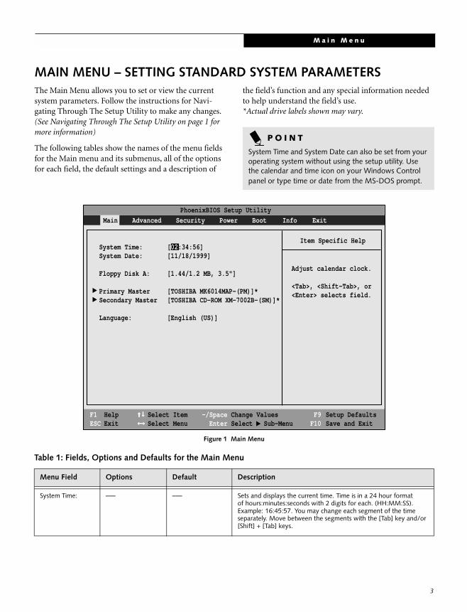
MAIN MENU – SETTING STANDARD SYSTEM PARAMETERSThe Main Menu allows you to set or view the current system parameters. Follow the instructions for Navi-gating Through The Setup Utility to make any changes. (See Navigating Through The Setup Utility on page 1 for more information)
The following tables show the names of the menu fields for the Main menu and its submenus, all of the options for each field, the default settings and a description of
the field’s function and any special information needed to help understand the field’s use.*Actual drive labels shown may vary.
Figure 1 Main Menu
P O I N T
System Time and System Date can also be set from your operating system without using the setup utility. Use the calendar and time icon on your Windows Control panel or type time or date from the MS-DOS prompt.
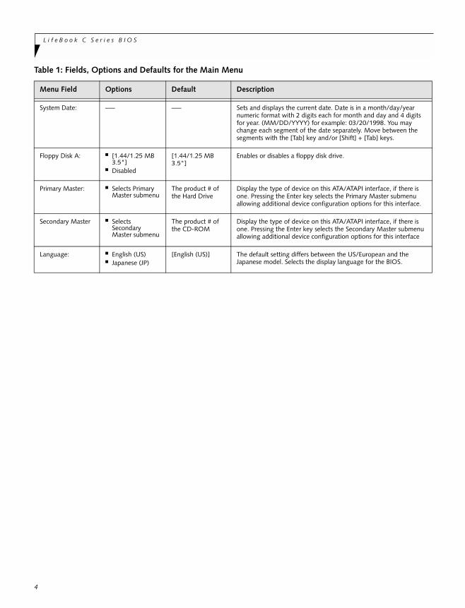
Table 1: Fields, Options and Defaults for the Main Menu
Menu Field Options Default Description
System Time: –— –— Sets and displays the current time. Time is in a 24 hour formatof hours:minutes:seconds with 2 digits for each. (HH:MM:SS). Example: 16:45:57. You may change each segment of the time separately. Move between the segments with the [Tab] key and/or [Shift] + [Tab] keys.
System Time: [02:34:56]System Date: [11/18/1999]
Floppy Disk A: [1.44/1.2 MB, 3.5"]
Primary Master [TOSHIBA MK6014MAP-(PM)]*Secondary Master [TOSHIBA CD-ROM XM-7002B-(SM)]*
Language: [English (US)]
PhoenixBIOS Setup Utility
F1 HelpESC Exit
Select ItemSelect Menu
-/Space Change Values Enter Select Sub-Menu
F9 Setup Defaults F10 Save and Exit
▲
Main Advanced Security Power Boot Info Exit
Item Specific Help
Adjust calendar clock.
<Tab>, <Shift-Tab>, or<Enter> selects field.
▲ ▲
3
L i f e B o o k C S e r i e s B I O S
4
System Date: –— –— Sets and displays the current date. Date is in a month/day/yearnumeric format with 2 digits each for month and day and 4 digits for year. (MM/DD/YYYY) for example: 03/20/1998. You maychange each segment of the date separately. Move between the segments with the [Tab] key and/or [Shift] + [Tab] keys.
Floppy Disk A: ■ [1.44/1.25 MB 3.5"]
■ Disabled
[1.44/1.25 MB 3.5"]
Enables or disables a floppy disk drive.
Primary Master: ■ Selects PrimaryMaster submenu
The product # of the Hard Drive
Display the type of device on this ATA/ATAPI interface, if there is one. Pressing the Enter key selects the Primary Master submenu allowing additional device configuration options for this interface.
Secondary Master ■ Selects Secondary Master submenu
The product # of the CD-ROM
Display the type of device on this ATA/ATAPI interface, if there is one. Pressing the Enter key selects the Secondary Master submenu allowing additional device configuration options for this interface
Language: ■ English (US)■ Japanese (JP)
[English (US)] The default setting differs between the US/European and theJapanese model. Selects the display language for the BIOS.
Table 1: Fields, Options and Defaults for the Main Menu
Menu Field Options Default Description
M a i n M e n u
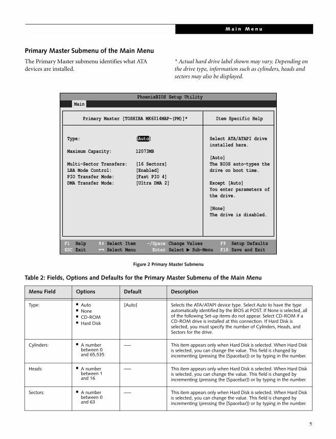
Primary Master Submenu of the Main Menu
The Primary Master submenu identifies what ATA devices are installed.
* Actual hard drive label shown may vary. Depending on the drive type, information such as cylinders, heads and sectors may also be displayed.
Figure 2 Primary Master Submenu
Table 2: Fields, Options and Defaults for the Primary Master Submenu of the Main Menu
Menu Field Options Default Description
Type: ■ Auto■ None■ CD-ROM■ Hard Disk
[Auto] Selects the ATA/ATAPI device type. Select Auto to have the type automatically identified by the BIOS at POST. If None is selected, all of the following Set-up items do not appear. Select CD-ROM if a CD-ROM drive is installed at this connection. If Hard Disk is selected, you must specify the number of Cylinders, Heads, and Sectors for the drive.
Cylinders: ■ A number between 0and 65,535
–— This item appears only when Hard Disk is selected. When Hard Disk is selected, you can change the value. This field is changed by incrementing (pressing the [Spacebar]) or by typing in the number.
Heads: ■ A number between 1and 16
–— This item appears only when Hard Disk is selected. When Hard Disk is selected, you can change the value. This field is changed by incrementing (pressing the [Spacebar]) or by typing in the number.
Sectors: ■ A number between 0and 63
–— This item appears only when Hard Disk is selected. When Hard Disk is selected, you can change the value. This field is changed by incrementing (pressing the [Spacebar]) or by typing in the number.
PhoenixBIOS Setup Utility
F1 HelpESC Exit
Select ItemSelect Menu
-/SpaceEnter
F9 Setup DefaultsF10 Save and Exit
Change ValuesSelect Sub-Menu
Main
Item Specific Help
Select ATA/ATAPI driveinstalled here.
[Auto]The BIOS auto-types thedrive on boot time.
Except [Auto]You enter parameters ofthe drive.
[None]The drive is disabled.
Primary Master [TOSHIBA MK6014MAP-(PM)]*
Type: [Auto]
Maximum Capacity: 12073MB
Multi-Sector Transfers: [16 Sectors]LBA Mode Control: [Enabled]PIO Transfer Mode: [Fast PIO 4]DMA Transfer Mode: [Ultra DMA 2]
▲
5
L i f e B o o k C S e r i e s B I O S
6
MaximumCapacity:
■ Display only –— Displays the maximum capacity of the drive calculated from the parameters of the hard disk when Hard Disk is selected.
Multi-SectorTransfers:
■ Disabled■ 2 Sectors■ 4 Sectors■ 8 Sectors■ 16 Sectors■ 32 Sectors■ 64 Sectors■ 128 Sectors
[16 Sectors] This option cannot be changed when Auto is selected. Specify the number of sectors per block for multiple sector transfer. MAX refers to the size the disk returns when required.
LBA Mode Control:
■ Enabled■ Disabled
[Enabled] Enables or disables logical Block Addressing in place of Cylinder, Head, Sector addressing. This option cannot be changed when Auto is selected.
PIO Transfer Mode:
■ Standard■ Fast PIO 1■ Fast PIO 2■ Fast PIO 3■ Fast PIO 4
[Fast PI0 4] Selects the method for moving data to/from the drive. Autotype the drive to select the optimum transfer mode. This option cannot be changed when Auto is selected. Multi-word DMA is automatically set to mode 1 for Fast PIO 1, Fast PIO 2, Fast PIO 3, and set to mode 2 for Fast PIO 4 / DMA.
DMA Transfer Mode:
■ Disabled■ Multiword
DMA 1■ Multiword
DMA 2■ Ultra DMA 0■ Ultra DMA 1■ Ultra DMA 2
[Ultra DMA 2] Selects the method for moving data to/from the drive. Autotype the drive to select the optimum transfer mode. This option cannot be changed when Auto is selected.
Table 2: Fields, Options and Defaults for the Primary Master Submenu of the Main Menu
Menu Field Options Default Description
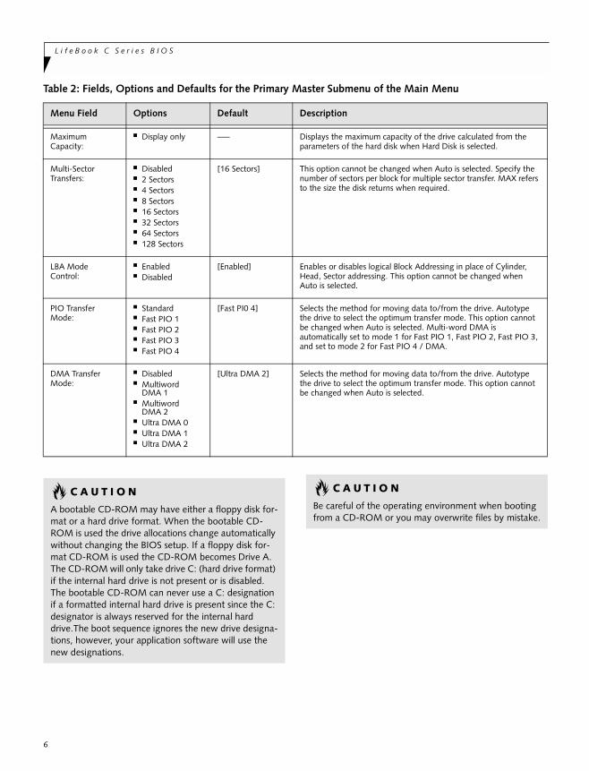
C A U T I O N
A bootable CD-ROM may have either a floppy disk for-mat or a hard drive format. When the bootable CD-ROM is used the drive allocations change automatically without changing the BIOS setup. If a floppy disk for-mat CD-ROM is used the CD-ROM becomes Drive A. The CD-ROM will only take drive C: (hard drive format) if the internal hard drive is not present or is disabled. The bootable CD-ROM can never use a C: designation if a formatted internal hard drive is present since the C: designator is always reserved for the internal hard drive.The boot sequence ignores the new drive designa-tions, however, your application software will use the new designations.
C A U T I O N
Be careful of the operating environment when booting from a CD-ROM or you may overwrite files by mistake.
M a i n M e n u
7
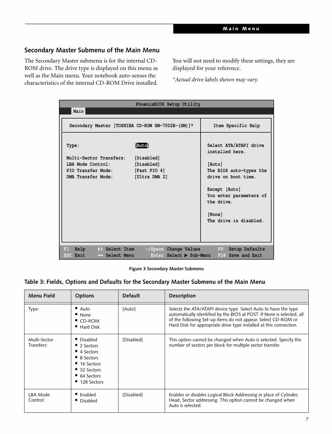
Secondary Master Submenu of the Main Menu
The Secondary Master submenu is for the internal CD-ROM drive. The drive type is displayed on this menu as well as the Main menu. Your notebook auto-senses the characteristics of the internal CD-ROM Drive installed.
You will not need to modify these settings, they are displayed for your reference.
*Actual drive labels shown may vary.
Figure 3 Secondary Master Submenu
Table 3: Fields, Options and Defaults for the Secondary Master Submenu of the Main Menu
Menu Field Options Default Description
Type: ■ Auto■ None■ CD-ROM■ Hard Disk
[Auto] Selects the ATA/ATAPI device type. Select Auto to have the type automatically identified by the BIOS at POST. If None is selected, all of the following Set-up items do not appear. Select CD-ROM or Hard Disk for appropriate drive type installed at this connection.
Multi-SectorTransfers:
■ Disabled■ 2 Sectors■ 4 Sectors■ 8 Sectors■ 16 Sectors■ 32 Sectors■ 64 Sectors■ 128 Sectors
[Disabled] This option cannot be changed when Auto is selected. Specify the number of sectors per block for multiple sector transfer.
LBA Mode Control:
■ Enabled■ Disabled
[Disabled] Enables or disables Logical Block Addressing in place of Cylinder, Head, Sector addressing. This option cannot be changed when Auto is selected.
PhoenixBIOS Setup Utility
F1 HelpESC Exit
Select ItemSelect Menu
-/SpaceEnter
F9 Setup DefaultsF10 Save and Exit
Change ValuesSelect Sub-Menu
Main
Item Specific Help
Select ATA/ATAPI driveinstalled here.
[Auto]The BIOS auto-types thedrive on boot time.
Except [Auto]You enter parameters ofthe drive.
[None]The drive is disabled.
Secondary Master [TOSHIBA CD-ROM XM-7002B-(SM)]*
Type: [Auto]
Multi-Sector Transfers: [Disabled]LBA Mode Control: [Disabled]PIO Transfer Mode: [Fast PIO 4]DMA Transfer Mode: [Ultra DMA 2]
▲
L i f e B o o k C S e r i e s B I O S
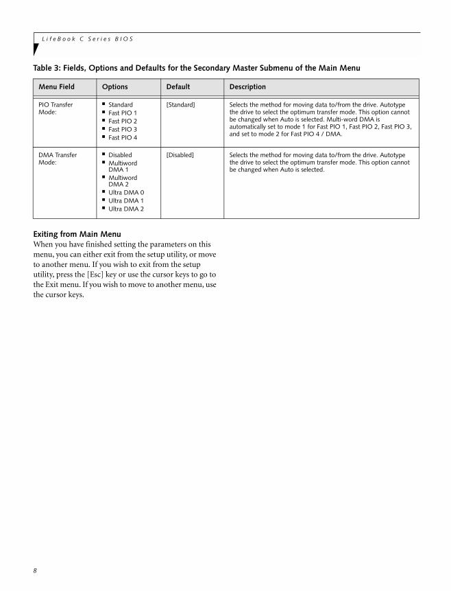
Exiting from Main MenuWhen you have finished setting the parameters on this menu, you can either exit from the setup utility, or move to another menu. If you wish to exit from the setup utility, press the [Esc] key or use the cursor keys to go to the Exit menu. If you wish to move to another menu, use the cursor keys.
PIO Transfer Mode:
■ Standard■ Fast PIO 1■ Fast PIO 2■ Fast PIO 3■ Fast PIO 4
[Standard] Selects the method for moving data to/from the drive. Autotype the drive to select the optimum transfer mode. This option cannot be changed when Auto is selected. Multi-word DMA is automatically set to mode 1 for Fast PIO 1, Fast PIO 2, Fast PIO 3, and set to mode 2 for Fast PIO 4 / DMA.
DMA Transfer Mode:
■ Disabled■ Multiword
DMA 1■ Multiword
DMA 2■ Ultra DMA 0■ Ultra DMA 1■ Ultra DMA 2
[Disabled] Selects the method for moving data to/from the drive. Autotype the drive to select the optimum transfer mode. This option cannot be changed when Auto is selected.
Table 3: Fields, Options and Defaults for the Secondary Master Submenu of the Main Menu
Menu Field Options Default Description
8
A d v a n c e d M e n u
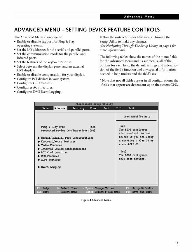
ADVANCED MENU – SETTING DEVICE FEATURE CONTROLSThe Advanced Menu allows you to:■ Enable or disable support for Plug & Play
operating systems.■ Set the I/O addresses for the serial and parallel ports.■ Set the communication mode for the parallel and
infrared ports.■ Set the features of the keyboard/mouse.■ Select between the display panel and an external
CRT display.■ Enable or disable compensation for your display.■ Configure PCI devices in your system.■ Configures CPU features.■ Configures ACPI features.■ Configures DMI Event Logging.
Follow the instructions for Navigating Through the Setup Utility to make any changes.(See Navigating Through The Setup Utility on page 1 for more information)
The following tables show the names of the menu fields for the Advanced Menu and its submenus, all of the options for each field, the default settings and a descrip-tion of the field’s function and any special information needed to help understand the field’s use.
* Note that not all fields appear in all configurations; the fields that appear are dependent upon the system CPU.
Figure 4 Advanced Menu
PhoenixBIOS Setup Utility
F1 HelpESC Exit
Select ItemSelect Menu
-/SpaceEnter
F9 Setup DefaultsF10 Save and Exit
Change ValuesSelect Sub-Menu
▲
Main Advanced Security Power Boot Info Exit
Item Specific Help
▲ ▲
▲ ▲
▲ ▲
▲
Plug & Play O/S: [Yes]Protected Device Configurations:[No]
Serial/Parallel Port ConfigurationsKeyboard/Mouse FeaturesVideo FeaturesInternal Device ConfigurationsPCI Configuration:CPU FeaturesACPI Features
Event Logging
[No]The BIOS configuresalso non-boot devices.Select if you are usinga non-Plug & Play OS ora non-ACPI OS.
[Yes]The BIOS configuresonly boot devices.
▲
9
L i f e B o o k C S e r i e s B I O S
10
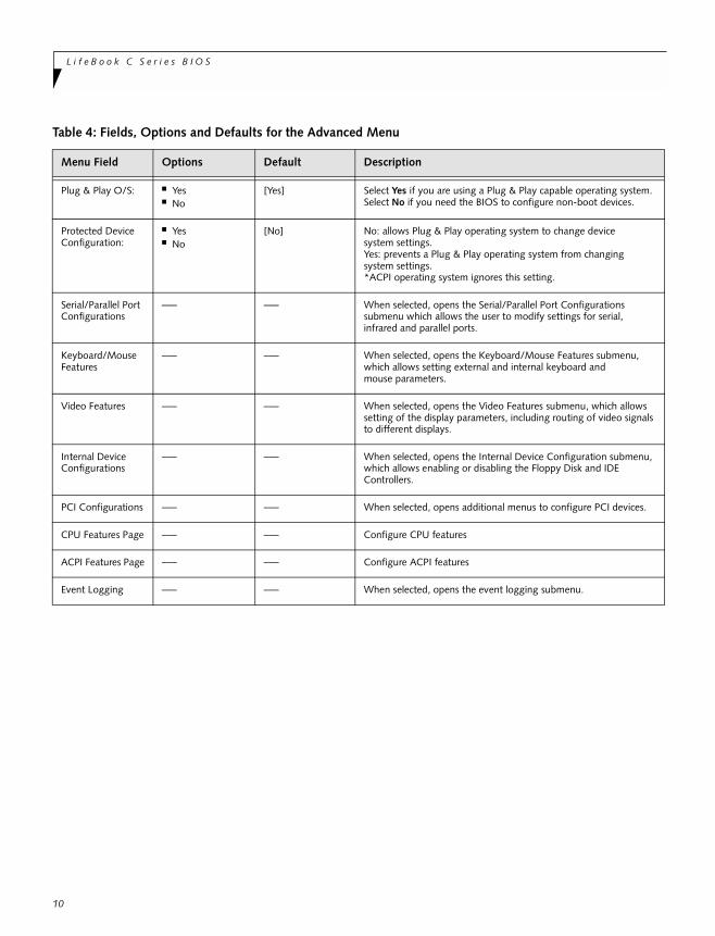
Table 4: Fields, Options and Defaults for the Advanced Menu
Menu Field Options Default Description
Plug & Play O/S: ■ Yes■ No
[Yes] Select Yes if you are using a Plug & Play capable operating system. Select No if you need the BIOS to configure non-boot devices.
Protected Device Configuration:
■ Yes■ No
[No] No: allows Plug & Play operating system to change device system settings. Yes: prevents a Plug & Play operating system from changing system settings. *ACPI operating system ignores this setting.
Serial/Parallel PortConfigurations
–— –— When selected, opens the Serial/Parallel Port Configurations submenu which allows the user to modify settings for serial, infrared and parallel ports.
Keyboard/Mouse Features
–— –— When selected, opens the Keyboard/Mouse Features submenu, which allows setting external and internal keyboard andmouse parameters.
Video Features –— –— When selected, opens the Video Features submenu, which allows setting of the display parameters, including routing of video signals to different displays.
Internal Device Configurations
–— –— When selected, opens the Internal Device Configuration submenu, which allows enabling or disabling the Floppy Disk and IDE Controllers.
PCI Configurations –— –— When selected, opens additional menus to configure PCI devices.
CPU Features Page –— –— Configure CPU features
ACPI Features Page –— –— Configure ACPI features
Event Logging –— –— When selected, opens the event logging submenu.
A d v a n c e d M e n u
11
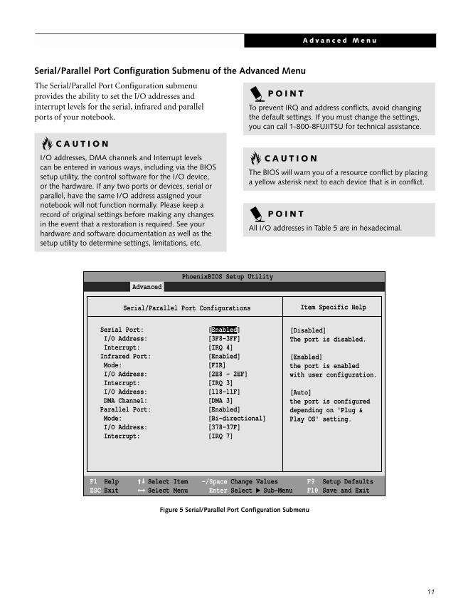
Serial/Parallel Port Configuration Submenu of the Advanced Menu
The Serial/Parallel Port Configuration submenu provides the ability to set the I/O addresses andinterrupt levels for the serial, infrared and parallelports of your notebook.
Figure 5 Serial/Parallel Port Configuration Submenu
C A U T I O N
I/O addresses, DMA channels and Interrupt levelscan be entered in various ways, including via the BIOS setup utility, the control software for the I/O device,or the hardware. If any two ports or devices, serial or parallel, have the same I/O address assigned your notebook will not function normally. Please keep a record of original settings before making any changesin the event that a restoration is required. See your hardware and software documentation as well as the setup utility to determine settings, limitations, etc.
P O I N T
To prevent IRQ and address conflicts, avoid changing the default settings. If you must change the settings, you can call 1-800-8FUJITSU for technical assistance.
C A U T I O N
The BIOS will warn you of a resource conflict by placing a yellow asterisk next to each device that is in conflict.
P O I N T
All I/O addresses in Table 5 are in hexadecimal.
PhoenixBIOS Setup Utility
F1 HelpESC Exit
Select ItemSelect Menu
-/SpaceEnter
F9 Setup DefaultsF10 Save and Exit
Change ValuesSelect Sub-Menu
▲
Advanced
Item Specific Help
Serial Port: [Enabled] I/O Address: [3F8-3FF] Interrupt: [IRQ 4]Infrared Port: [Enabled] Mode: [FIR] I/O Address: [2E8 - 2EF] Interrupt: [IRQ 3] I/O Address: [118-11F] DMA Channel: [DMA 3]Parallel Port: [Enabled] Mode: [Bi-directional] I/O Address: [378-37F] Interrupt: [IRQ 7]
[Disabled]The port is disabled.
[Enabled]the port is enabledwith user configuration.
[Auto]the port is configureddepending on 'Plug &Play OS' setting.
Serial/Parallel Port Configurations
L i f e B o o k C S e r i e s B I O S
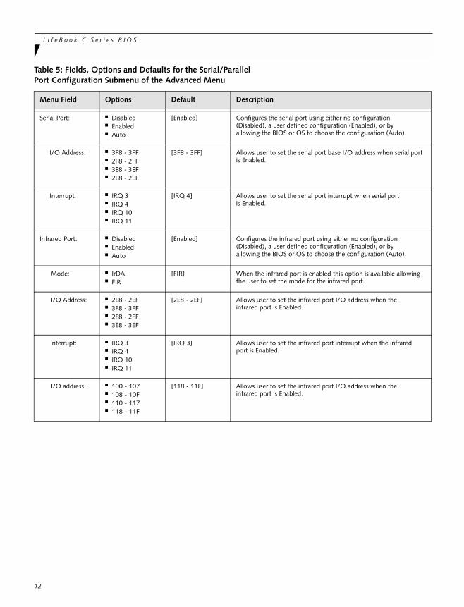
Table 5: Fields, Options and Defaults for the Serial/Parallel Port Configuration Submenu of the Advanced Menu
Menu Field Options Default Description
Serial Port: ■ Disabled■ Enabled■ Auto
[Enabled] Configures the serial port using either no configuration(Disabled), a user defined configuration (Enabled), or byallowing the BIOS or OS to choose the configuration (Auto).
I/O Address: ■ 3F8 - 3FF■ 2F8 - 2FF■ 3E8 - 3EF■ 2E8 - 2EF
[3F8 - 3FF] Allows user to set the serial port base I/O address when serial port is Enabled.
Interrupt: ■ IRQ 3■ IRQ 4■ IRQ 10■ IRQ 11
[IRQ 4] Allows user to set the serial port interrupt when serial port is Enabled.
Infrared Port: ■ Disabled■ Enabled■ Auto
[Enabled] Configures the infrared port using either no configuration(Disabled), a user defined configuration (Enabled), or byallowing the BIOS or OS to choose the configuration (Auto).
Mode: ■ IrDA■ FIR
[FIR] When the infrared port is enabled this option is available allowing the user to set the mode for the infrared port.
I/O Address: ■ 2E8 - 2EF■ 3F8 - 3FF■ 2F8 - 2FF■ 3E8 - 3EF
[2E8 - 2EF] Allows user to set the infrared port I/O address when theinfrared port is Enabled.
Interrupt: ■ IRQ 3■ IRQ 4■ IRQ 10■ IRQ 11
[IRQ 3] Allows user to set the infrared port interrupt when the infraredport is Enabled.
I/O address: ■ 100 - 107■ 108 - 10F■ 110 - 117■ 118 - 11F
[118 - 11F] Allows user to set the infrared port I/O address when theinfrared port is Enabled.
12
A d v a n c e d M e n u
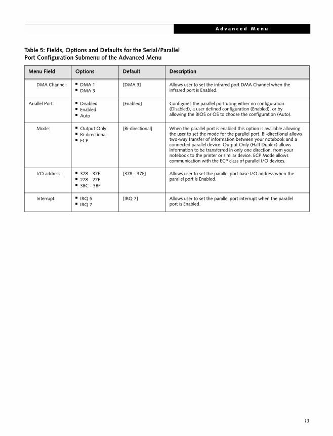
DMA Channel: ■ DMA 1■ DMA 3
[DMA 3] Allows user to set the infrared port DMA Channel when the infrared port is Enabled.
Parallel Port: ■ Disabled■ Enabled■ Auto
[Enabled] Configures the parallel port using either no configuration(Disabled), a user defined configuration (Enabled), or byallowing the BIOS or OS to choose the configuration (Auto).
Mode: ■ Output Only■ Bi-directional■ ECP
[Bi-directional] When the parallel port is enabled this option is available allowing the user to set the mode for the parallel port. Bi-directional allows two-way transfer of information between your notebook and aconnected parallel device. Output Only (Half Duplex) allowsinformation to be transferred in only one direction, from yournotebook to the printer or similar device. ECP Mode allowscommunication with the ECP class of parallel I/O devices.
I/O address: ■ 378 - 37F■ 278 - 27F■ 3BC - 3BF
[378 - 37F] Allows user to set the parallel port base I/O address when theparallel port is Enabled.
Interrupt: ■ IRQ 5■ IRQ 7
[IRQ 7] Allows user to set the parallel port interrupt when the parallelport is Enabled.
Table 5: Fields, Options and Defaults for the Serial/Parallel Port Configuration Submenu of the Advanced Menu
Menu Field Options Default Description
13
L i f e B o o k C S e r i e s B I O S
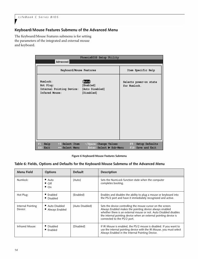
Keyboard/Mouse Features Submenu of the Advanced Menu
The Keyboard/Mouse Features submenu is for setting the parameters of the integrated and external mouse and keyboard.
Figure 6 Keyboard/Mouse Features Submenu
Table 6: Fields, Options and Defaults for the Keyboard/Mouse Submenu of the Advanced Menu
Menu Field Options Default Description
Numlock: ■ Auto■ Off■ On
[Auto] Sets the NumLock function state when the computercompletes booting.
Hot Plug: ■ Enabled■ Disabled
[Enabled] Enables and disables the ability to plug a mouse or keyboard intothe PS/2 port and have it immediately recognized and active.
Internal Pointing Device:
■ Auto Disabled■ Always Enabled
[Auto Disabled] Sets the device controlling the mouse cursor on the screen.Always Enabled makes the pointing device always enabledwhether there is an external mouse or not. Auto Disabled disables the internal pointing device when an external pointing device is connected to the PS/2 port.
Infrared Mouse: ■ Disabled■ Enabled
[Disabled] If IR Mouse is enabled, the PS/2 mouse is disabled. If you want to use the internal pointing device with the IR Mouse, you must select Always Enabled in the Internal Pointing Device.
F1 HelpESC Exit
Select ItemSelect Menu
-/SpaceEnter
F9 Setup DefaultsF10 Save and Exit
Change ValuesSelect Sub-Menu
▲
Advanced Security Power Savings Exit
Item Specific Help
PhoenixBIOS Setup Utility
Selects power-on statefor Numlock.
Keyboard/Mouse Features
Numlock:Hot Plug:Internal Pointing Device:Infared Mouse:
[Auto][Enabled][Auto Disabled][Disabled]
14
A d v a n c e d M e n u
15
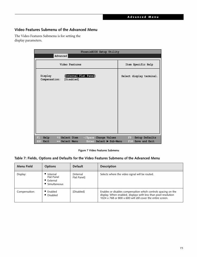
Video Features Submenu of the Advanced Menu
The Video Features Submenu is for setting the display parameters.
Figure 7 Video Features Submenu
Table 7: Fields, Options and Defaults for the Video Features Submenu of the Advanced Menu
Menu Field Options Default Description
Display: ■ Internal Flat Panel
■ External■ Simultaneous
[Internal Flat Panel]
Selects where the video signal will be routed.
Compensation: ■ Enabled■ Disabled
[Disabled] Enables or disables compensation which controls spacing on thedisplay. When enabled, displays with less than pixel resolution1024 x 768 or 800 x 600 will still cover the entire screen.
Display [Internal Flat Panel]Compensation: [Disabled]
F1 HelpESC Exit
Select ItemSelect Menu
-/SpaceEnter
F9 Setup DefaultsF10 Save and Exit
Change ValuesSelect Sub-Menu
▲
Main Advanced Security Power Savings Exit
Item Specific Help
Select display terminal.
Video Features
PhoenixBIOS Setup Utility
L i f e B o o k C S e r i e s B I O S
16
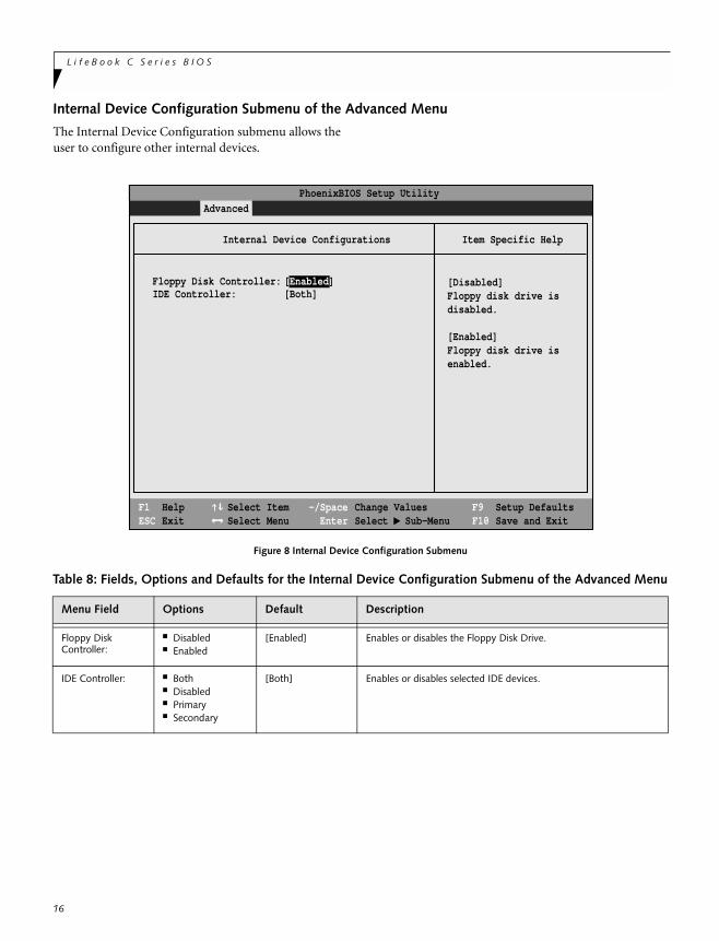
Internal Device Configuration Submenu of the Advanced Menu
The Internal Device Configuration submenu allows the user to configure other internal devices.
Figure 8 Internal Device Configuration Submenu
Table 8: Fields, Options and Defaults for the Internal Device Configuration Submenu of the Advanced Menu
Menu Field Options Default Description
Floppy Disk Controller:
■ Disabled■ Enabled
[Enabled] Enables or disables the Floppy Disk Drive.
IDE Controller: ■ Both■ Disabled■ Primary■ Secondary
[Both] Enables or disables selected IDE devices.
F1 HelpESC Exit
Select ItemSelect Menu
-/SpaceEnter
F9 Setup DefaultsF10 Save and Exit
Change ValuesSelect Sub-Menu
▲
Main Advanced Security Power Savings Exit
Item Specific Help
[Disabled]Floppy disk drive isdisabled.
[Enabled]Floppy disk drive isenabled.
Internal Device Configurations
PhoenixBIOS Setup Utility
Floppy Disk Controller: [Enabled]IDE Controller: [Both]
A d v a n c e d M e n u
17
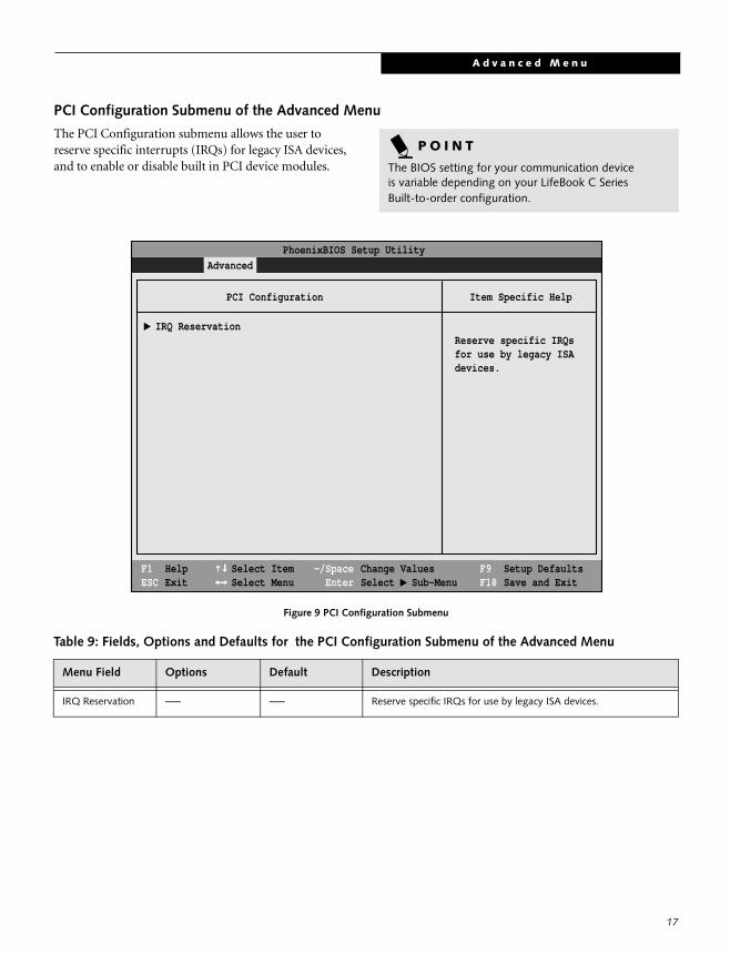
PCI Configuration Submenu of the Advanced Menu
The PCI Configuration submenu allows the user to reserve specific interrupts (IRQs) for legacy ISA devices, and to enable or disable built in PCI device modules.
Figure 9 PCI Configuration Submenu
P O I N T
The BIOS setting for your communication deviceis variable depending on your LifeBook C SeriesBuilt-to-order configuration.
Table 9: Fields, Options and Defaults for the PCI Configuration Submenu of the Advanced Menu
Menu Field Options Default Description
IRQ Reservation –— –— Reserve specific IRQs for use by legacy ISA devices.
F1 HelpESC Exit
Select ItemSelect Menu
-/SpaceEnter
F9 Setup DefaultsF10 Save and Exit
Change ValuesSelect Sub-Menu
▲
Main Advanced Security Power Savings Exit
Item Specific Help
Reserve specific IRQsfor use by legacy ISAdevices.
PCI Configuration
IRQ Reservation
PhoenixBIOS Setup Utility
▲
L i f e B o o k C S e r i e s B I O S
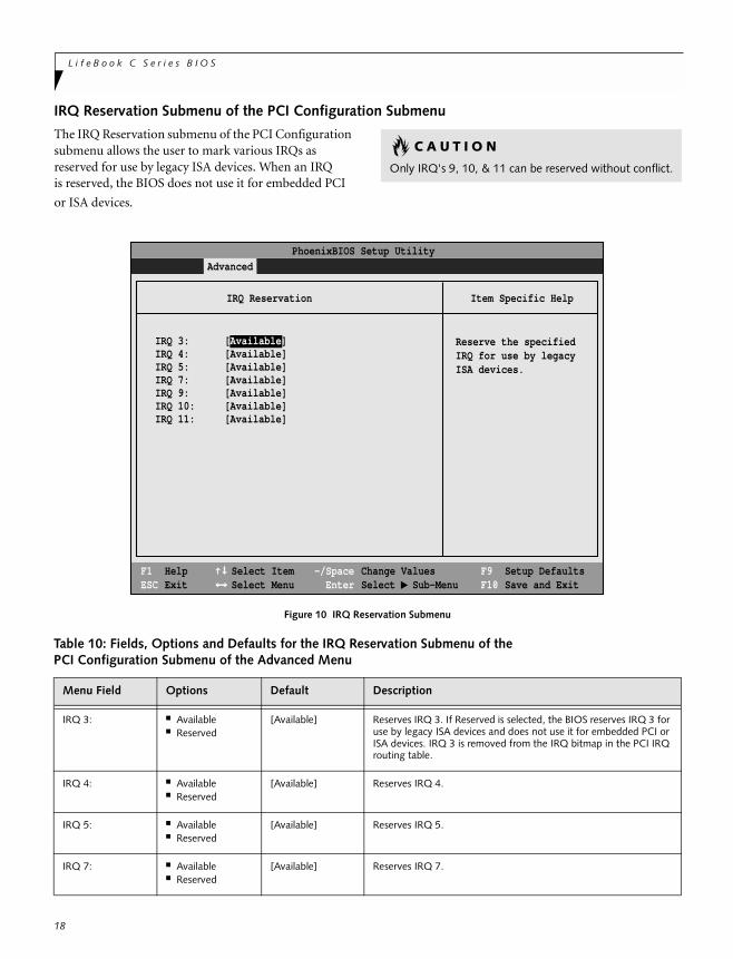
IRQ Reservation Submenu of the PCI Configuration Submenu
The IRQ Reservation submenu of the PCI Configuration submenu allows the user to mark various IRQs as reserved for use by legacy ISA devices. When an IRQis reserved, the BIOS does not use it for embedded PCI
or ISA devices.
Figure 10 IRQ Reservation Submenu
C A U T I O N
Only IRQ's 9, 10, & 11 can be reserved without conflict.
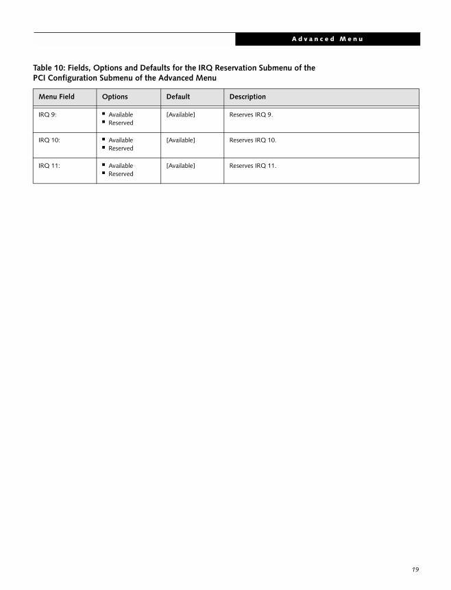
Table 10: Fields, Options and Defaults for the IRQ Reservation Submenu of thePCI Configuration Submenu of the Advanced Menu
Menu Field Options Default Description
IRQ 3: ■ Available■ Reserved
[Available] Reserves IRQ 3. If Reserved is selected, the BIOS reserves IRQ 3 for use by legacy ISA devices and does not use it for embedded PCI or ISA devices. IRQ 3 is removed from the IRQ bitmap in the PCI IRQ routing table.
IRQ 4: ■ Available■ Reserved
[Available] Reserves IRQ 4.
IRQ 5: ■ Available■ Reserved
[Available] Reserves IRQ 5.
IRQ 7: ■ Available■ Reserved
[Available] Reserves IRQ 7.
F1 HelpESC Exit
Select ItemSelect Menu
-/SpaceEnter
F9 Setup DefaultsF10 Save and Exit
Change ValuesSelect Sub-Menu
▲
Main Advanced Security Power Savings Exit
Item Specific Help
Reserve the specifiedIRQ for use by legacyISA devices.
IRQ Reservation
PhoenixBIOS Setup Utility
IRQ 3: [Available]IRQ 4: [Available]IRQ 5: [Available]IRQ 7: [Available]IRQ 9: [Available]IRQ 10: [Available]IRQ 11: [Available]
18
A d v a n c e d M e n u
IRQ 9: ■ Available■ Reserved
[Available] Reserves IRQ 9.
IRQ 10: ■ Available■ Reserved
[Available] Reserves IRQ 10.
IRQ 11: ■ Available■ Reserved
[Available] Reserves IRQ 11.
Table 10: Fields, Options and Defaults for the IRQ Reservation Submenu of thePCI Configuration Submenu of the Advanced Menu
Menu Field Options Default Description
19
L i f e B o o k C S e r i e s B I O S
20
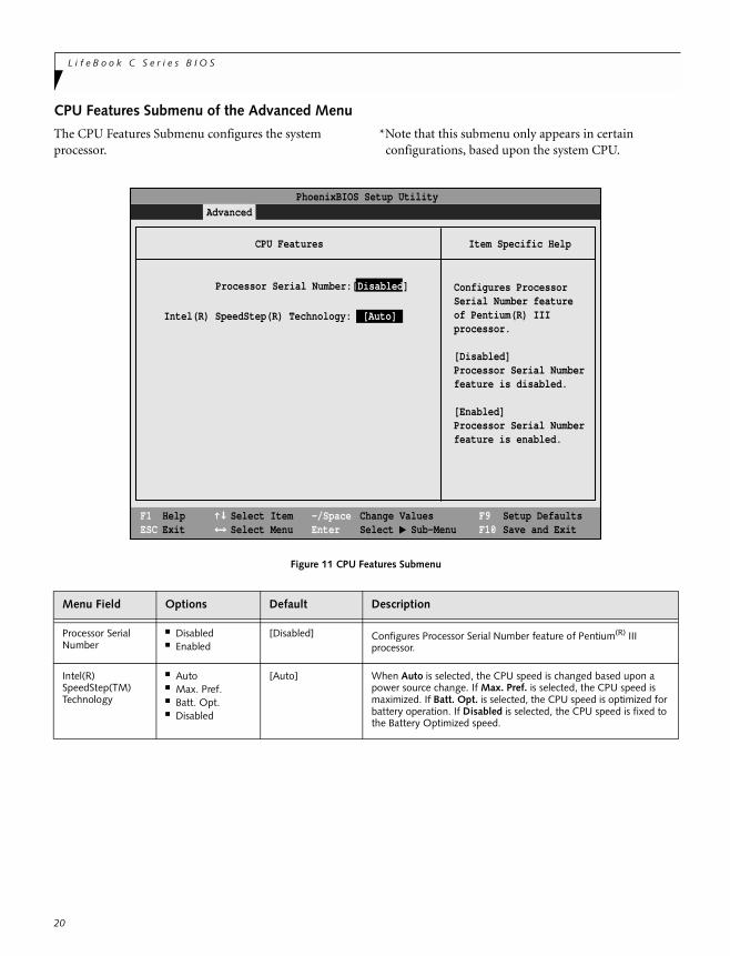
CPU Features Submenu of the Advanced Menu
The CPU Features Submenu configures the system processor.
*Note that this submenu only appears in certain configurations, based upon the system CPU.
Figure 11 CPU Features Submenu
Menu Field Options Default Description
Processor Serial Number
■ Disabled■ Enabled
[Disabled] Configures Processor Serial Number feature of Pentium(R) III processor.
Intel(R) SpeedStep(TM) Technology
■ Auto■ Max. Pref.■ Batt. Opt.■ Disabled
[Auto] When Auto is selected, the CPU speed is changed based upon a power source change. If Max. Pref. is selected, the CPU speed is maximized. If Batt. Opt. is selected, the CPU speed is optimized for battery operation. If Disabled is selected, the CPU speed is fixed to the Battery Optimized speed.
F1 HelpESC Exit
Select ItemSelect Menu
-/SpaceEnter
F9 Setup DefaultsF10 Save and Exit
Change ValuesSelect Sub-Menu
▲
Main Advanced Security Power Savings Exit
Item Specific Help
PhoenixBIOS Setup Utility
Configures ProcessorSerial Number featureof Pentium(R) IIIprocessor.
[Disabled]Processor Serial Numberfeature is disabled.
[Enabled]Processor Serial Numberfeature is enabled.
CPU Features
Processor Serial Number:[Disabled]
Intel(R) SpeedStep(R) Technology: [Auto]
A d v a n c e d M e n u
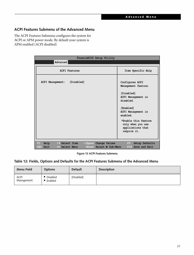
ACPI Features Submenu of the Advanced Menu
The ACPI Features Submenu configures the system for ACPI or APM power mode. By default your system is APM enabled (ACPI disabled)
Figure 12 ACPI Features Submenu
Table 12: Fields, Options and Defaults for the ACPI Features Submenu of the Advanced Menu
Menu Field Options Default Description
ACPIManagement:
■ Disabled■ Enabled
[Disabled]
F1 HelpESC Exit
Select ItemSelect Menu
-/SpaceEnter
F9 Setup DefaultsF10 Save and Exit
Change ValuesSelect Sub-Menu
▲
Main Advanced Security Power Savings Exit
Item Specific Help
Configures ACPIManagement feature.
[Disabled]ACPI Management isdisabled.
[Enabled]ACPI Management isenabled.
ACPI Features
PhoenixBIOS Setup Utility
ACPI Management: [Disabled]
*Enable this feature only when you use applications that require it.
21
L i f e B o o k C S e r i e s B I O S
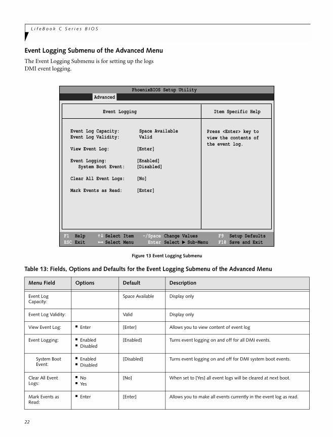
Event Logging Submenu of the Advanced Menu
The Event Logging Submenu is for setting up the logs DMI event logging.
Figure 13 Event Logging Submenu
Table 13: Fields, Options and Defaults for the Event Logging Submenu of the Advanced Menu
Menu Field Options Default Description
Event Log Capacity:
Space Available Display only
Event Log Validity: Valid Display only
View Event Log: ■ Enter [Enter] Allows you to view content of event log
Event Logging: ■ Enabled■ Disabled
[Enabled] Turns event logging on and off for all DMI events.
System Boot Event:
■ Enabled■ Disabled
[Disabled] Turns event logging on and off for DMI system boot events.
Clear All Event Logs:
■ No■ Yes
[No] When set to [Yes] all event logs will be cleared at next boot.
Mark Events as Read:
■ Enter [Enter] Allows you to make all events currently in the event log as read.
F1 HelpESC Exit
Select ItemSelect Menu
-/SpaceEnter
F9 Setup DefaultsF10 Save and Exit
Change ValuesSelect Sub-Menu
▲
Main Advanced Security Power Savings Exit
Item Specific Help
Press <Enter> key toview the contents ofthe event log.
Event Logging
PhoenixBIOS Setup Utility
Event Log Capacity: Space AvailableEvent Log Validity: Valid
View Event Log: [Enter]
Event Logging: [Enabled] System Boot Event: [Disabled]
Clear All Event Logs: [No]
Mark Events as Read: [Enter]
22
S e c u r i t y M e n u
SECURITY MENU – SETTING THE SECURITY FEATURESThe Security menu allows you to set up the data security features of your notebook to fit your operating needs and to view the current data security configuration. Follow the instructions for Navigating Through the Setup Utility to make any changes. (See Navigating Through The Setup Utility on page 1 for more information)
The following tables show the names of the menu fields for the Security menu and its submenus, all of the options for each field, the default settings and a description of the field's function and any special information needed to help understand the field's use. The default condition is no passwords required and no write protection.
P O I N T
If you set a password, write it down and keep it in a safe place. If you forget the password you will have to contact your support representative to regain access to your secured functions and data.
C A U T I O N
Entering a password incorrectly 3 times in a row will cause the keyboard and mouse to be locked out and the warning [System Disabled] to be displayed. If this happens restart the computer by turning off and on the power with the power switch and use the correct password on reboot.
P O I N T
If you make an error when re-entering the passworda [Warning] will be displayed on the screen. To try again press the Enter key and then retype the password. Press the Esc key to abort the password setting process.
C A U T I O N
If Password On Resume is Enabled and Password On Boot is Disabled you will not have to type your password upon resuming the system from the Suspend or Save-to-Disk modes. Password On Resume will work only if Password On Boot is enabled.
P O I N T
Boot sector protection must be set to [Normal] to install or upgrade an operating system.
23
L i f e B o o k C S e r i e s B I O S
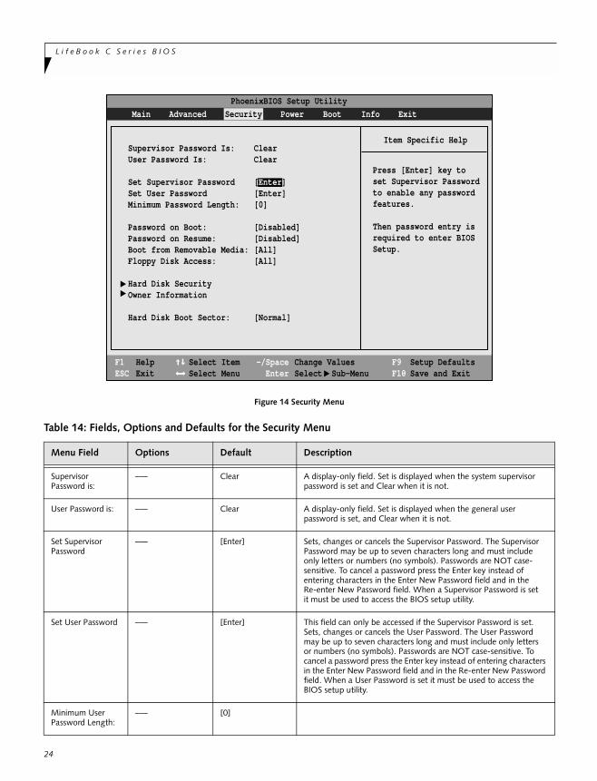
Figure 14 Security Menu
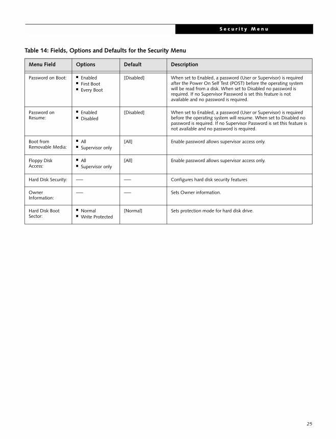
Table 14: Fields, Options and Defaults for the Security Menu
Menu Field Options Default Description
SupervisorPassword is:
–— Clear A display-only field. Set is displayed when the system supervisor password is set and Clear when it is not.
User Password is: –— Clear A display-only field. Set is displayed when the general userpassword is set, and Clear when it is not.
Set Supervisor Password
–— [Enter] Sets, changes or cancels the Supervisor Password. The SupervisorPassword may be up to seven characters long and must include only letters or numbers (no symbols). Passwords are NOT case- sensitive. To cancel a password press the Enter key instead ofentering characters in the Enter New Password field and in theRe-enter New Password field. When a Supervisor Password is setit must be used to access the BIOS setup utility.
Set User Password –— [Enter] This field can only be accessed if the Supervisor Password is set.Sets, changes or cancels the User Password. The User Password may be up to seven characters long and must include only letters or numbers (no symbols). Passwords are NOT case-sensitive. To cancel a password press the Enter key instead of entering characters in the Enter New Password field and in the Re-enter New Password field. When a User Password is set it must be used to access the BIOS setup utility.
Minimum User Password Length:
–— [0]
F1 HelpESC Exit
Select ItemSelect Menu
-/SpaceEnter
F9 Setup DefaultsF10 Save and Exit
Change ValuesSelect Sub-Menu
▲
Main Advanced Security Power Boot Info Exit
Item Specific Help
Press [Enter] key toset Supervisor Passwordto enable any passwordfeatures.
Then password entry isrequired to enter BIOSSetup.
PhoenixBIOS Setup Utility
Supervisor Password Is: ClearUser Password Is: Clear
Set Supervisor Password [Enter]Set User Password [Enter]Minimum Password Length: [0] Password on Boot: [Disabled]Password on Resume: [Disabled]Boot from Removable Media: [All]Floppy Disk Access: [All]
Hard Disk SecurityOwner Information
Hard Disk Boot Sector: [Normal]
▲ ▲
24
S e c u r i t y M e n u
Password on Boot: ■ Enabled■ First Boot■ Every Boot
[Disabled] When set to Enabled, a password (User or Supervisor) is required after the Power On Self Test (POST) before the operating system will be read from a disk. When set to Disabled no password is required. If no Supervisor Password is set this feature is not available and no password is required.
Password on Resume:
■ Enabled■ Disabled
[Disabled] When set to Enabled, a password (User or Supervisor) is required before the operating system will resume. When set to Disabled no password is required. If no Supervisor Password is set this feature is not available and no password is required.
Boot from Removable Media:
■ All■ Supervisor only
[All] Enable password allows supervisor access only.
Floppy Disk Access:
■ All■ Supervisor only
[All] Enable password allows supervisor access only.
Hard Disk Security: –— –— Configures hard disk security features
Owner Information:
–— –— Sets Owner information.
Hard Disk Boot Sector:
■ Normal■ Write Protected
[Normal] Sets protection mode for hard disk drive.
Table 14: Fields, Options and Defaults for the Security Menu
Menu Field Options Default Description
25
L i f e B o o k C S e r i e s B I O S
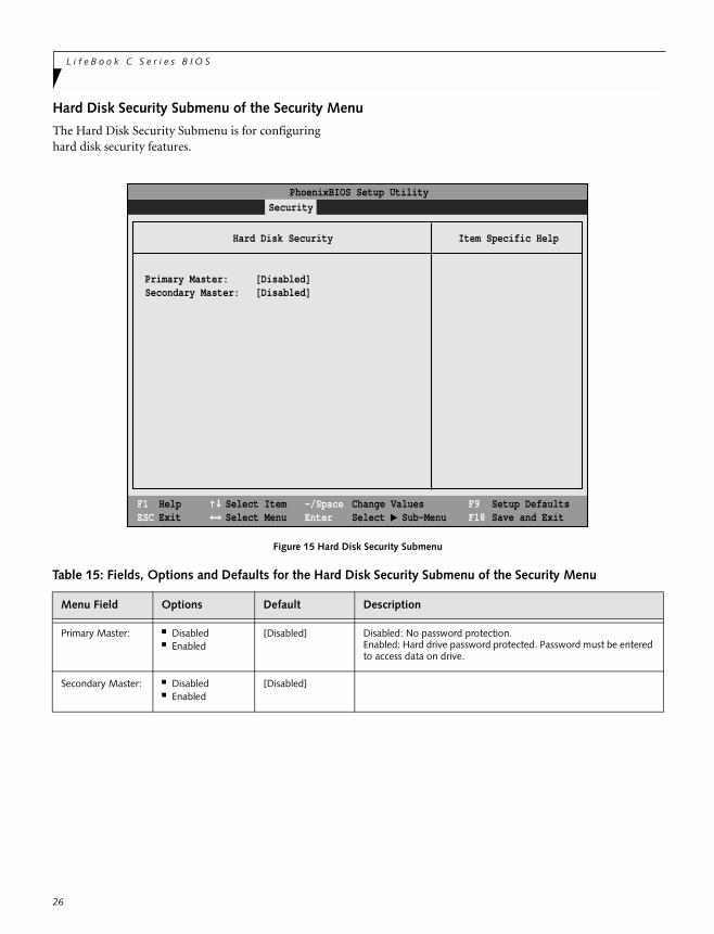
Hard Disk Security Submenu of the Security Menu
The Hard Disk Security Submenu is for configuring hard disk security features.
Figure 15 Hard Disk Security Submenu
Table 15: Fields, Options and Defaults for the Hard Disk Security Submenu of the Security Menu
Menu Field Options Default Description
Primary Master: ■ Disabled■ Enabled
[Disabled] Disabled: No password protection.Enabled: Hard drive password protected. Password must be entered to access data on drive.
Secondary Master: ■ Disabled■ Enabled
[Disabled]
F1 HelpESC Exit
Select ItemSelect Menu
-/SpaceEnter
F9 Setup DefaultsF10 Save and Exit
Change ValuesSelect Sub-Menu
▲
Main Advanced Security Power Savings Exit
Item Specific Help
PhoenixBIOS Setup Utility
Hard Disk Security
Primary Master: [Disabled]Secondary Master: [Disabled]
26
S e c u r i t y M e n u
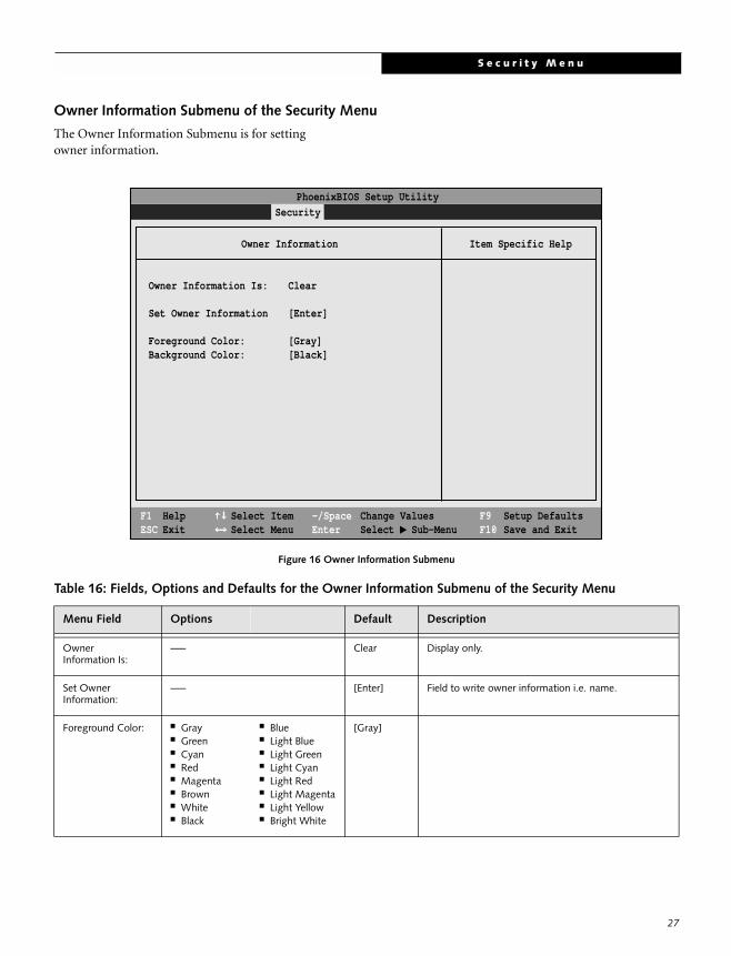
Owner Information Submenu of the Security Menu
The Owner Information Submenu is for setting owner information.
Figure 16 Owner Information Submenu
Table 16: Fields, Options and Defaults for the Owner Information Submenu of the Security Menu
Menu Field Options Default Description
Owner Information Is:
–— Clear Display only.
Set Owner Information:
–— [Enter] Field to write owner information i.e. name.
Foreground Color: ■ Gray ■ Green■ Cyan■ Red■ Magenta■ Brown■ White■ Black
■ Blue■ Light Blue■ Light Green■ Light Cyan■ Light Red■ Light Magenta■ Light Yellow■ Bright White
[Gray]
F1 HelpESC Exit
Select ItemSelect Menu
-/SpaceEnter
F9 Setup DefaultsF10 Save and Exit
Change ValuesSelect Sub-Menu
▲
Main Advanced Security Power Savings Exit
Item Specific Help
PhoenixBIOS Setup Utility
Owner Information
Owner Information Is: Clear
Set Owner Information [Enter]
Foreground Color: [Gray]Background Color: [Black]
27
L i f e B o o k C S e r i e s B I O S
28
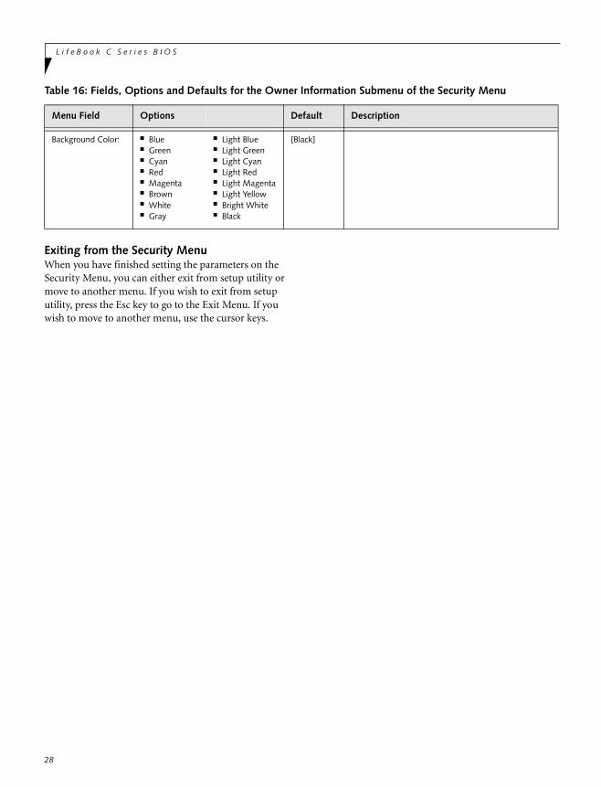
Exiting from the Security MenuWhen you have finished setting the parameters on the Security Menu, you can either exit from setup utility or move to another menu. If you wish to exit from setup utility, press the Esc key to go to the Exit Menu. If you wish to move to another menu, use the cursor keys.
Background Color: ■ Blue ■ Green■ Cyan■ Red■ Magenta■ Brown■ White■ Gray
■ Light Blue■ Light Green■ Light Cyan■ Light Red■ Light Magenta■ Light Yellow■ Bright White■ Black
[Black]
Table 16: Fields, Options and Defaults for the Owner Information Submenu of the Security Menu
Menu Field Options Default Description
P o w e r M e n u
POWER MENU – SETTING POWER MANAGEMENT FEATURES The Power menu allows you to set and change the power management parameters. Follow the instructions for Navigating Through the Setup Utility to make any changes. (See Navigating Through The Setup Utility on page 1 for more information)
The following tables show the names of the menu fields for the Power menu and its submenus, all of the options for each field, the default settings and a description of the field's function and any special information needed to help understand the field's use.
P O I N T
In Windows 98 Auto-suspend Timeout, Hard Disk Timeout, and Video Timeout features are available exclusively through the operating system.
P O I N T
When resuming from a Save-to-Disk suspension there will be a delay while the contents of system memory and operating parameters are loaded from the hard drive.
C A U T I O N
In Save-to-Disk mode there is no indication on the Status Indicator to let you know you are suspended rather than shut off from the power switch. You may want to make a habit of always trying the Suspend/Resume button before using the power switch.
C A U T I O N
Wake on Modem ring when enabled will draw power from the bridge battery alone when your system is running off battery power. this may potentially drain your bridge battery. Disabling Wake on Modem ring will prevent this from happening.
29
L i f e B o o k C S e r i e s B I O S
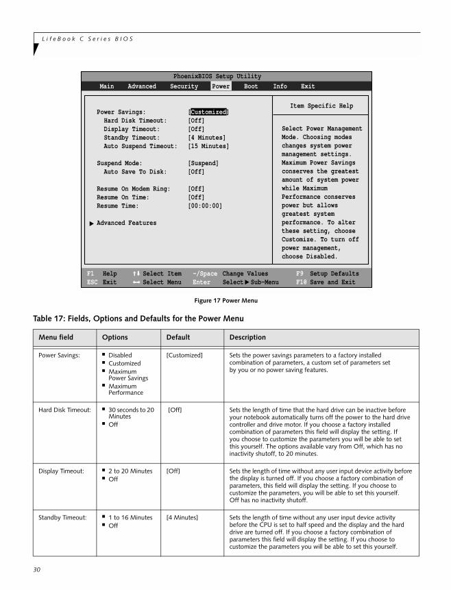
Figure 17 Power Menu
Table 17: Fields, Options and Defaults for the Power Menu
Menu field Options Default Description
Power Savings: ■ Disabled■ Customized■ Maximum
Power Savings■ Maximum
Performance
[Customized] Sets the power savings parameters to a factory installedcombination of parameters, a custom set of parameters setby you or no power saving features.
Hard Disk Timeout: ■ 30 seconds to 20 Minutes
■ Off
[Off] Sets the length of time that the hard drive can be inactive before your notebook automatically turns off the power to the hard drivecontroller and drive motor. If you choose a factory installedcombination of parameters this field will display the setting. Ifyou choose to customize the parameters you will be able to setthis yourself. The options available vary from Off, which has noinactivity shutoff, to 20 minutes.
Display Timeout: ■ 2 to 20 Minutes■ Off
[Off] Sets the length of time without any user input device activity before the display is turned off. If you choose a factory combination of parameters, this field will display the setting. If you choose tocustomize the parameters, you will be able to set this yourself.Off has no inactivity shutoff.
Standby Timeout: ■ 1 to 16 Minutes■ Off
[4 Minutes] Sets the length of time without any user input device activitybefore the CPU is set to half speed and the display and the harddrive are turned off. If you choose a factory combination ofparameters this field will display the setting. If you choose tocustomize the parameters you will be able to set this yourself.
Power Savings: [Customized] Hard Disk Timeout: [Off] Display Timeout: [Off] Standby Timeout: [4 Minutes] Auto Suspend Timeout: [15 Minutes]
Suspend Mode: [Suspend] Auto Save To Disk: [Off]
Resume On Modem Ring: [Off]Resume On Time: [Off]Resume Time: [00:00:00]
Advanced Features
F1 HelpESC Exit
Select ItemSelect Menu
-/SpaceEnter
F9 Setup DefaultsF10 Save and Exit
Change ValuesSelect Sub-Menu
▲
Item Specific Help
Select Power ManagementMode. Choosing modeschanges system powermanagement settings.Maximum Power Savingsconserves the greatestamount of system powerwhile MaximumPerformance conservespower but allowsgreatest systemperformance. To alterthese setting, chooseCustomize. To turn offpower management,choose Disabled.
PhoenixBIOS Setup Utility
▲
Main Advanced Security Power Boot Info Exit
30
P o w e r M e n u
31
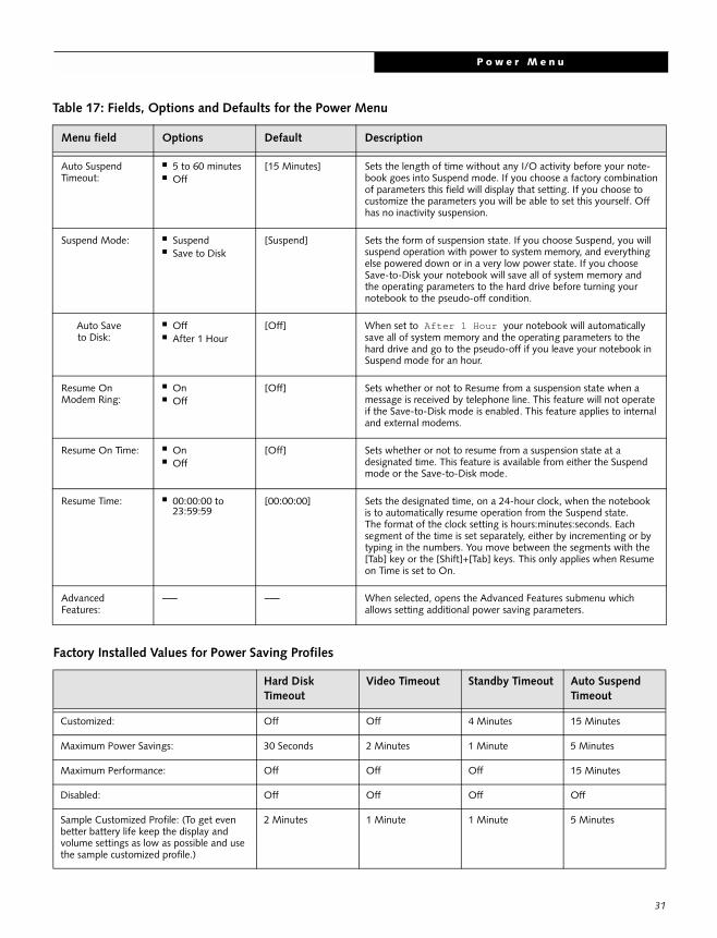
Auto SuspendTimeout:
■ 5 to 60 minutes■ Off
[15 Minutes] Sets the length of time without any I/O activity before your note-book goes into Suspend mode. If you choose a factory combinationof parameters this field will display that setting. If you choose tocustomize the parameters you will be able to set this yourself. Offhas no inactivity suspension.
Suspend Mode: ■ Suspend■ Save to Disk
[Suspend] Sets the form of suspension state. If you choose Suspend, you willsuspend operation with power to system memory, and everythingelse powered down or in a very low power state. If you chooseSave-to-Disk your notebook will save all of system memory andthe operating parameters to the hard drive before turning yournotebook to the pseudo-off condition.
Auto Saveto Disk:
■ Off■ After 1 Hour
[Off] When set to After 1 Hour your notebook will automatically save all of system memory and the operating parameters to the hard drive and go to the pseudo-off if you leave your notebook in Suspend mode for an hour.
Resume On Modem Ring:
■ On■ Off
[Off] Sets whether or not to Resume from a suspension state when amessage is received by telephone line. This feature will not operateif the Save-to-Disk mode is enabled. This feature applies to internaland external modems.
Resume On Time: ■ On■ Off
[Off] Sets whether or not to resume from a suspension state at adesignated time. This feature is available from either the Suspendmode or the Save-to-Disk mode.
Resume Time: ■ 00:00:00 to23:59:59
[00:00:00] Sets the designated time, on a 24-hour clock, when the notebookis to automatically resume operation from the Suspend state.The format of the clock setting is hours:minutes:seconds. Eachsegment of the time is set separately, either by incrementing or bytyping in the numbers. You move between the segments with the[Tab] key or the [Shift]+[Tab] keys. This only applies when Resume on Time is set to On.
AdvancedFeatures:
–— –— When selected, opens the Advanced Features submenu whichallows setting additional power saving parameters.
Factory Installed Values for Power Saving Profiles
Hard DiskTimeout
Video Timeout Standby Timeout Auto Suspend Timeout
Customized: Off Off 4 Minutes 15 Minutes
Maximum Power Savings: 30 Seconds 2 Minutes 1 Minute 5 Minutes
Maximum Performance: Off Off Off 15 Minutes
Disabled: Off Off Off Off
Sample Customized Profile: (To get even better battery life keep the display and volume settings as low as possible and use the sample customized profile.)
2 Minutes 1 Minute 1 Minute 5 Minutes
Table 17: Fields, Options and Defaults for the Power Menu
Menu field Options Default Description
L i f e B o o k C S e r i e s B I O S
32
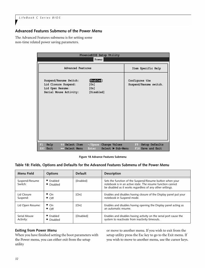
Advanced Features Submenu of the Power Menu
The Advanced Features submenu is for setting some non-time related power saving parameters.
Figure 18 Advance Features Submenu
Exiting from Power MenuWhen you have finished setting the boot parameters with the Power menu, you can either exit from the setup utility
or move to another menu. If you wish to exit from the setup utility press the Esc key to go to the Exit menu. If you wish to move to another menu, use the cursor keys.
Table 18: Fields, Options and Defaults for the Advanced Features Submenu of the Power Menu
Menu Field Options Default Description
Suspend/Resume Switch:
■ Enabled■ Disabled
[Enabled] Sets the function of the Suspend/Resume button when your notebook is in an active state. The resume function cannotbe disabled as it works regardless of any other settings.
Lid ClosureSuspend:
■ On■ Off
[On] Enables and disables having closure of the Display panel put yournotebook in Suspend mode.
Lid Open Resume: ■ On■ Off
[On] Enables and disables having opening the Display panel acting asan automatic resume.
Serial Mouse Activity:
■ Enabled■ Disabled
[Disabled] Enables and disables having activity on the serial port cause thesystem to reactivate from inactivity timeouts.
PhoenixBIOS Setup Utility
F1 HelpESC Exit
Select ItemSelect Menu
-/SpaceEnter
F9 Setup DefaultsF10 Save and Exit
Change ValuesSelect Sub-Menu
Item Specific Help
Configures theSuspend/Resume switch.
▲
Power
Advanced Features
Suspend/Resume Switch: [Enabled]Lid Closure Suspend: [On]Lid Open Resume: [On]Serial Mouse Activity: [Disabled]
B o o t M e n u
33
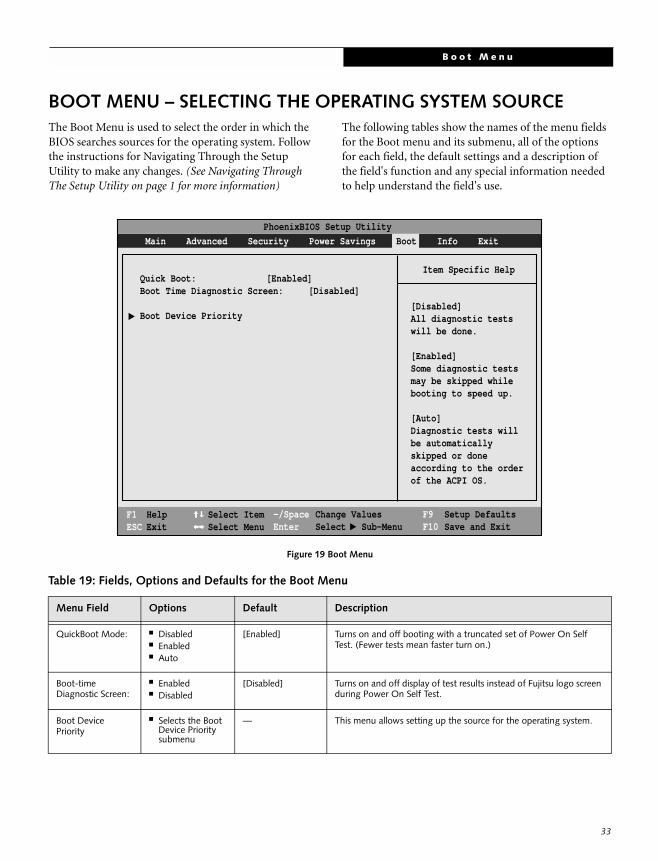
BOOT MENU – SELECTING THE OPERATING SYSTEM SOURCEThe Boot Menu is used to select the order in which the BIOS searches sources for the operating system. Follow the instructions for Navigating Through the Setup Utility to make any changes. (See Navigating Through The Setup Utility on page 1 for more information)
The following tables show the names of the menu fields for the Boot menu and its submenu, all of the options for each field, the default settings and a description of the field's function and any special information needed to help understand the field's use.
Figure 19 Boot Menu
Table 19: Fields, Options and Defaults for the Boot Menu
Menu Field Options Default Description
QuickBoot Mode: ■ Disabled■ Enabled■ Auto
[Enabled] Turns on and off booting with a truncated set of Power On Self Test. (Fewer tests mean faster turn on.)
Boot-timeDiagnostic Screen:
■ Enabled■ Disabled
[Disabled] Turns on and off display of test results instead of Fujitsu logo screen during Power On Self Test.
Boot DevicePriority
■ Selects the Boot Device Prioritysubmenu
— This menu allows setting up the source for the operating system.
PhoenixBIOS Setup Utility
F1 HelpESC Exit
Select ItemSelect Menu
Item Specific Help
[Disabled]All diagnostic testswill be done.
[Enabled]Some diagnostic testsmay be skipped whilebooting to speed up.
[Auto]Diagnostic tests willbe automaticallyskipped or doneaccording to the orderof the ACPI OS.
Quick Boot: [Enabled]Boot Time Diagnostic Screen: [Disabled]
Boot Device Priority
▲
-/SpaceEnter
F9 Setup DefaultsF10 Save and Exit
Change ValuesSelect Sub-Menu
▲
Main Advanced Security Power Savings Boot Info Exit
34
L i f e B o o k C S e r i e s B I O S
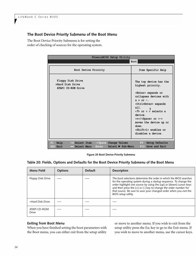
The Boot Device Priority Submenu of the Boot Menu
The Boot Device Priority Submenu is for setting the order of checking of sources for the operating system.
Figure 20 Boot Device Priority Submenu
Exiting from Boot MenuWhen you have finished setting the boot parameters with the Boot menu, you can either exit from the setup utility
or move to another menu. If you wish to exit from the setup utility press the Esc key to go to the Exit menu. If you wish to move to another menu, use the cursor keys.
Table 20: Fields, Options and Defaults for the Boot Device Priority Submenu of the Boot Menu
Menu Field Options Default Description
Floppy Disk Drive –— –— The boot selections determine the order in which the BIOS searches for the operating system during a startup sequence. To change the order highlight one source by using the [up] or [down] cursor keys and then press the [+] or [-] key to change the order number for that source. Be sure to save your changed order when you exit the BIOS setup utility.
+Hard Disk Drive –— –— –—
ATAPI CD-ROM Drive
–— –— –—
PhoenixBIOS Setup Utility
F1 HelpESC Exit
Select ItemSelect Menu
Main Advanced Security Power Savings Boot
Item Specific Help
The top device has thehighest priority.
<Enter> expands orcollapses devices witha + or -.<Ctrl+Enter> expandsall.< > or < > selects adevice.<+>/<Space> or <->moves the device up ordown.<Shift+1> enables ordisables a device.
Floppy Disk Drive+Hard Disk Drive ATAPI CD-ROM Drive
-/SpaceEnter
F9 Setup DefaultsF10 Save and Exit
Change ValuesSelect Sub-Menu
▲
Boot Device Priority
➞
➞
I n f o M e n u
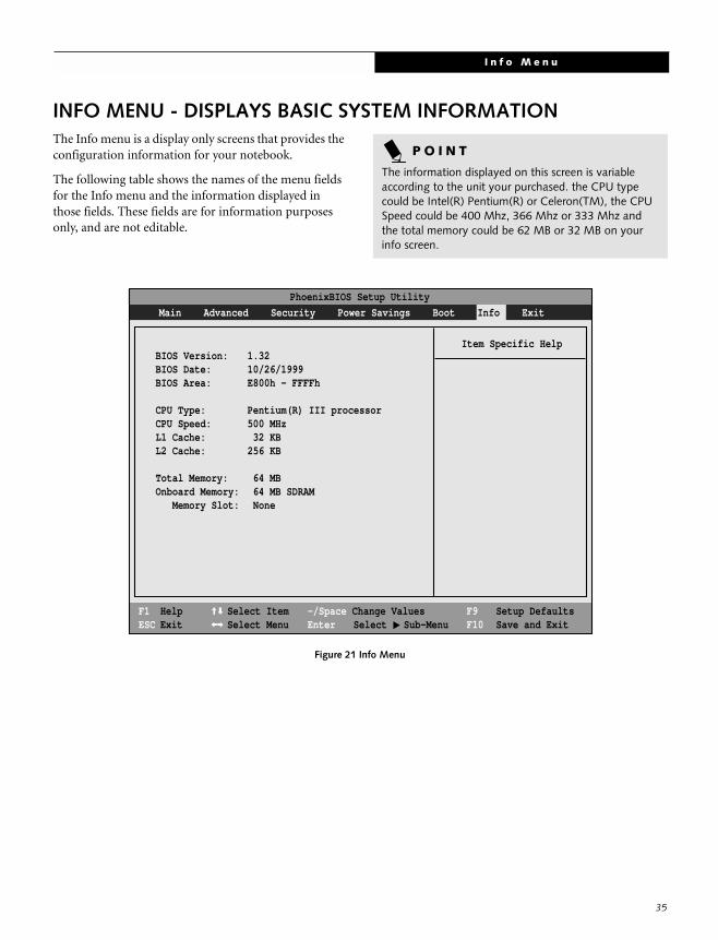
INFO MENU - DISPLAYS BASIC SYSTEM INFORMATIONThe Info menu is a display only screens that provides the configuration information for your notebook.
The following table shows the names of the menu fields for the Info menu and the information displayed in those fields. These fields are for information purposes only, and are not editable.
Figure 21 Info Menu
P O I N T
The information displayed on this screen is variable according to the unit your purchased. the CPU type could be Intel(R) Pentium(R) or Celeron(TM), the CPU Speed could be 400 Mhz, 366 Mhz or 333 Mhz and the total memory could be 62 MB or 32 MB on your info screen.
PhoenixBIOS Setup Utility
F1 HelpESC Exit
Select ItemSelect Menu
-/Space Change Values Enter Select Sub-Menu
F9 Setup DefaultsF10 Save and Exit
Main Advanced Security Power Savings Boot Info Exit
Item Specific HelpBIOS Version: 1.32BIOS Date: 10/26/1999BIOS Area: E800h - FFFFh
CPU Type: Pentium(R) III processor CPU Speed: 500 MHzL1 Cache: 32 KBL2 Cache: 256 KB
Total Memory: 64 MBOnboard Memory: 64 MB SDRAM Memory Slot: None
▲
35
L i f e B o o k C S e r i e s B I O S
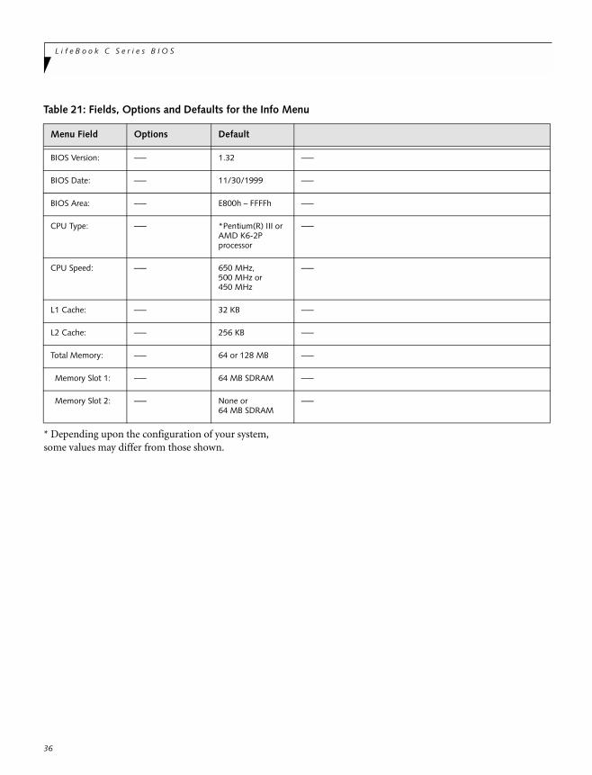
* Depending upon the configuration of your system, some values may differ from those shown.
Table 21: Fields, Options and Defaults for the Info Menu
Menu Field Options Default
BIOS Version: –— 1.32 –—
BIOS Date: –— 11/30/1999 –—
BIOS Area: –— E800h – FFFFh –—
CPU Type: –— *Pentium(R) III or AMD K6-2Pprocessor
–—
CPU Speed: –— 650 MHz,500 MHz or450 MHz
–—
L1 Cache: –— 32 KB –—
L2 Cache: –— 256 KB –—
Total Memory: –— 64 or 128 MB –—
Memory Slot 1: –— 64 MB SDRAM –—
Memory Slot 2: –— None or 64 MB SDRAM
–—
36

E x i t M e n u
EXIT MENU – LEAVING THE SETUP UTILITYThe Exit Menu is used to leave the setup utility. Follow the instructions for Navigating Through the Setup Utility to make any changes. (See Navigating Through The Setup Utility on page 1 for more information)
The following table shows the names of the menu fields for the Exit menu, the default settings and a description of the field's function and any special information needed to help understand the field's use.
Figure 22 Exit Menu
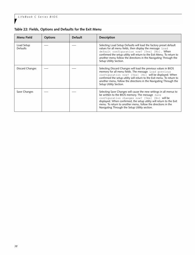
Table 22: Fields, Options and Defaults for the Exit Menu
Menu Field Options Default Description
Exit Saving Changes
–— –— Exit Saving Changes and Exit will store all the entries on everymenu of the setup utility to the BIOS memory and then exit thesetup utility. A confirmation message Save Configuration changes and exit now? [Yes] [No] will be displayed.
Exit Discarding Changes
–— –— Selecting Exit Discarding Changes and Exit will exit the setup utility with out writing to the BIOS memory. A setup warning message Configuration has not been saved! Save before exiting? [Yes] [No] will be displayed when your settings have changed. When the BIOS recognizes the Exit Discarding Changes selection it will load the operating system and begin operation.
PhoenixBIOS Setup Utility
F1 HelpESC Exit
Select ItemSelect Menu
-/Space Change Values Enter Select Sub-Menu
F9 Setup DefaultsF10 Save and Exit
Main Advanced Security Power Savings Boot Exit
Item Specific Help
Exit System Setup andsave your changes toCMOS.
Exit Saving ChangesExit Discarding ChangesLoad Setup DefaultsDiscard Changes Save Changes
▲
37
L i f e B o o k C S e r i e s B I O S
Load Setup Defaults
–— –— Selecting Load Setup Defaults will load the factory preset default values for all menu fields, then display the message Load default configuration now? [Yes] [No]. When confirmed the setup utility will return to the Exit Menu. To return to another menu follow the directions in the Navigating Through the Setup Utility Section.
Discard Changes –— –— Selecting Discard Changes will load the previous values in BIOS memory for all menu fields. The message Load previous configuration now? [Yes] [No] will be displayed. When confirmed the setup utility will return to the Exit menu. To return to another menu, follow the directions in the Navigating Through the Setup Utility Section.
Save Changes –— –— Selecting Save Changes will cause the new settings in all menus to be written to the BIOS memory. The message Save configuration changes now? [Yes] [No] will be displayed. When confirmed, the setup utility will return to the Exit menu. To return to another menu, follow the directions in the Navigating Through the Setup Utility section.
Table 22: Fields, Options and Defaults for the Exit Menu
Menu Field Options Default Description
38