Embed Size (px)
Citation preview
ww
w.sla
mte
c.com
Shanghai Slamtec.Co.,Ltd
RPLIDAR 360 Degree Laser Range Scanner
Interface Protocol and Application Notes
Applied to RPLIDAR A and S Series
2019
-03-28 rev.2
.1
CONTENTS ................................................................................................................................................... 3
OVERVIEW ................................................................................................................................................... 3
SDK AND DEMO PROGRAM .............................................................................................................................. 3
PROTOCOL BASICS .................................................................................................................................... 4
BASIC COMMUNICATION MODE ........................................................................................................................ 4
REQUEST PACKETS’ FORMAT ........................................................................................................................... 6
RESPONSE PACKETS’ FORMAT ......................................................................................................................... 7
WORKING STATE AND MECHANISM ................................................................................................. 10
MAJOR WORKING STATES AND TRANSITION CONDITIONS ............................................................................ 10
SCANNING STATUS ........................................................................................................................................... 11
REQUEST AND RESPONSE DATA ......................................................................................................... 12
SCAN MODE AND MEASUREMENT FREQUENCY .............................................................................................. 12
REQUESTS OVERVIEW ....................................................................................................................................... 13
STOP REQUEST ................................................................................................................................................ 13
RPLIDAR CORE RESET(RESET) REQUEST ...................................................................................................... 14
START SCAN(SCAN) REQUEST AND RESPONSE ......................................................................................... 14
EXPRESS SCAN(EXPRESS_SCAN) REQUEST AND RESPONSE ........................................................................ 17
FORCE SCAN(FORCE_SCAN) REQUEST AND RESPONSE ............................................................................... 32
GET DEVICE INFO (GET_INFO) REQUEST AND RESPONSE ............................................................................. 33
GET DEVICE HEALTH STATUS (GET_HEALTH) REQUEST AND RESPONSE ..................................................... 35
GET SAMPLE RATE(GET_SAMPLERATE) REQUEST ........................................................................................ 36
DEVICE CONFIGURATION QUERY COMMAND (GET_LIDAR_CONF) .............................................................. 37
DEVICE MOTOR SPEED CONTROL COMMAND (MOTOR_SPEED_CTRL) ....................................................... 43
APPLICATION NOTES ............................................................................................................................. 44
TYPICAL WORK FLOW OF RETRIEVING SCANNING DATA FROM AN RPLIDAR ................................................. 44
CALCULATE RPLIDAR SCANNING SPEED ........................................................................................................ 45
REVISION HISTORY ................................................................................................................................. 47
APPENDIX .................................................................................................................................................. 48
IMAGE AND TABLE INDEX ................................................................................................................................. 48

3 / 49
Copyright (c) 2009-2013 RoboPeak Team
Copyright (c) 2013-2019 Shanghai Slamtec Co., Ltd.
The host system communicates with RPLIDAR core system via the TTL UART serial
interface. Based on the communication protocol defined in this document, the host
system can retrieve the scan data, the device status, the health information etc. and
manipulate RPLIDAR’s working mode.
Figure 1-1 The Communication Between RPLIDAR and Host System
Please refer to the RPLIDAR datasheet for information about the bottom layer
communication protocol and the electrical level definition of the serial signals used
to communicate with RPLIDAR. The communication protocol based on UART serial
port and the data transmission format will be introduced in this document.
SDK and Demo Program
SLAMTEC provides open-sourced SDK and demo program for customers to
integrate RPLIDAR into their systems quickly. The SDK implements all the
communication stacks, driver logics and related data structures described in this
document. The public SDK is open-sourced and can be retrieved from GitHub:
https://github.com/slamtec/rplidar_sdk .
The SDK supports multiple platforms including Windows, Linux, MacOS and even
bare systems without an OS.
Please refer to the SDK manual for details.
Overview
TX
RX
GND
Host System
4 / 49
Copyright (c) 2009-2013 RoboPeak Team
Copyright (c) 2013-2019 Shanghai Slamtec Co., Ltd.
Basic Communication Mode
The RPLIDAR uses a non-textual binary data packet based protocol to communicate
with host systems. And all the packets transmitted on the interface channel share
uniform packet formats.
A communication session is always initialized by a host system, i.e. a MCU, a PC, etc.
RPLIDAR itself won’t send any data out automatically after powering up.
If a data packet is sent from host systems to RPLIDARs, such a packet is called a
Request. Once an RPLIAR receives a request, it will reply the host system with a data
packet called a Response.
RPLIDAR will only start performing related operations required by a host system
once after it receives a request. If RPLIDAR should reply to the host system, it will
send one or more required response packets.
In order to let an RPLIDAR start scanning operation and send out data, a host system
is required to send a pre-defined Start Scan request packet to RPLIDAR. RPLIDAR
will start scanning operation once after it receives the request and the scan result
data is sent out to the host system continuously.
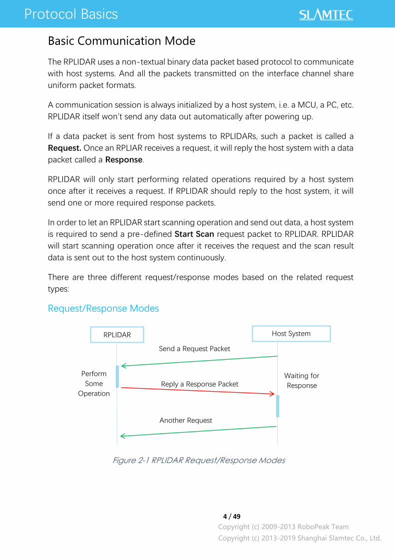
There are three different request/response modes based on the related request
types:
Request/Response Modes
Figure 2-1 RPLIDAR Request/Response Modes
Protocol Basics
RPLIDAR Host System
Send a Request Packet
Perform
Some
Operation Reply a Response Packet
Waiting for
Response
Another Request

5 / 49
Copyright (c) 2009-2013 RoboPeak Team
Copyright (c) 2013-2019 Shanghai Slamtec Co., Ltd.
Host system should prevent sending extra request packets if the RPLIDAR is busy
with handing the current request and hasn’t replied to the host system yet.
Otherwise,
these extra request packets will be discarded by the RPLIDAR’s protocol stack and
the RPLIDAR will not have any chance to handle it.
Single Request-Multiple Response Modes
This mode is used when the RPLIAR is asked to perform the scan operation. After a
host system sending a Start Scan request, RPLIDAR will take distance scan
measurement continuously. Once a scan measurement sample is retrieved, its
related result data (distance, angle value) will be sent out as individual response
packets.
Host systems are only required to send a single request packet with this mode but
will receive a continuous response packet stream with multiple response packets.
Figure 2-2 RPLIDAR Single Request - Multiple Response Mode
The host system can interrupt RPLIDAR and let it leave the multiple responses mode
by sending a STOP request or any request packet. After leaving the multiple
RPLIDAR Host System
Send a Start Scan
Request
Initialization Reply a response descriptor
Waiting for
response
Prepare for
receiving
Scan
Operation
Measurement Sample1
Measurement Sample2
Receiving data
… Measurement Samplen
Another response Exit the scan
operation
Handle other
responses
6 / 49
Copyright (c) 2009-2013 RoboPeak Team
Copyright (c) 2013-2019 Shanghai Slamtec Co., Ltd.
responses mode, the RPLIDAR will continue to handle the request which has
interrupted it.
The request packets sent by the host system during the multiple responses mode
will be cached by the RPLIDAR’s protocol stack. After leaving the multiple responses
mode, RPLIDAR will handle the cached request.
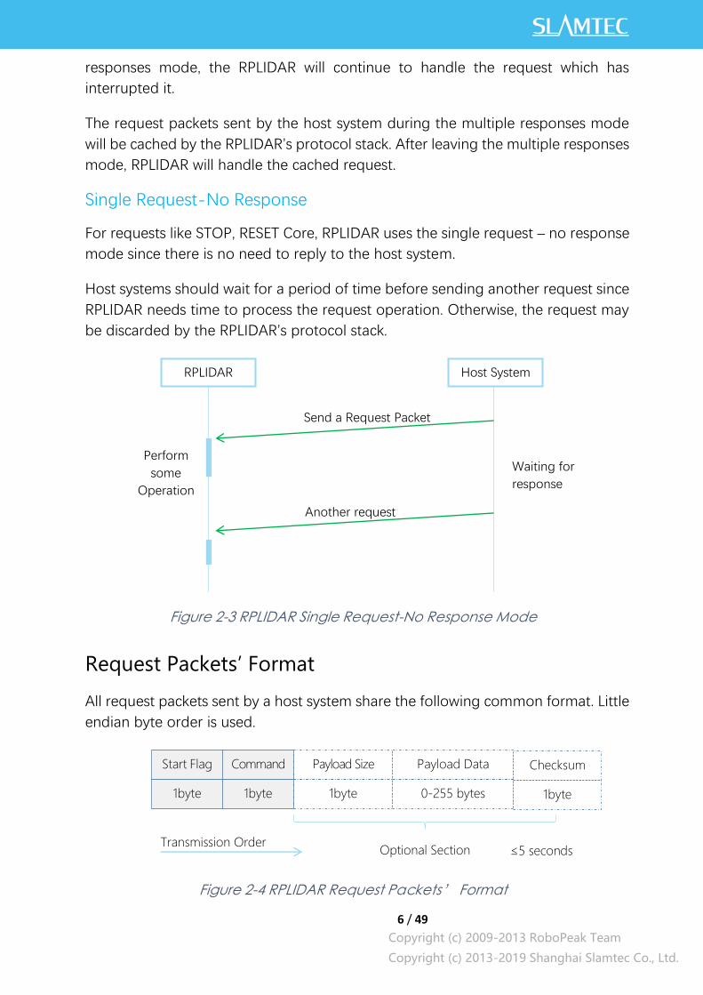
Single Request-No Response
For requests like STOP, RESET Core, RPLIDAR uses the single request – no response
mode since there is no need to reply to the host system.
Host systems should wait for a period of time before sending another request since
RPLIDAR needs time to process the request operation. Otherwise, the request may
be discarded by the RPLIDAR’s protocol stack.
Figure 2-3 RPLIDAR Single Request-No Response Mode
Request Packets’ Format
All request packets sent by a host system share the following common format. Little
endian byte order is used.
Figure 2-4 RPLIDAR Request Packets’ Format
RPLIDAR Host System
Send a Request Packet
Perform
some
Operation
Waiting for
response
Another request
Start Flag Command Payload Size Payload Data Checksum
1byte
(0xA5)
1byte 1byte 0-255 bytes 1byte
Optional Section Transmission Order
≤5 seconds

7 / 49
Copyright (c) 2009-2013 RoboPeak Team
Copyright (c) 2013-2019 Shanghai Slamtec Co., Ltd.
A fixed 0xA5 byte is used for each request packet, RPLIDAR uses this byte as the
identification of a new request packet. An 8bit (1byte) command field must follow
the start flag byte.
If the current request carries extra payload data, an 8bit (1byte) payload size field is
required to be transmitted after sending the command field and then follows the
payload data. After the payload data has been transmitted, an 8bit (1byte) checksum
field calculated from the previous sent data should be transmitted.
The checksum value can be calculated using the following equation:
checksum = 0 ⨁ 0𝑥𝐴5 ⨁ 𝐶𝑚𝑑𝑇𝑦𝑝𝑒 ⨁ 𝑃𝑎𝑦𝑙𝑜𝑎𝑑𝑆𝑖𝑧𝑒 ⨁ 𝑃𝑎𝑦𝑙𝑜𝑎𝑑[0] ⨁ … ⨁𝑃𝑎𝑦𝑙𝑜𝑎𝑑[𝑛]
Note: Timing Consideration
All bytes within a request packet must be transmitted to RPLIDAR within 5 seconds.
Otherwise, the communication stack of RPLIDAR will discard the current request
packet.
Response Packets’ Format
All the response packets are divided into two classes: response descriptors and
data responses. If the current request received by RPLIDAR requires a response,
RPLDAR will always send a response descriptor packet first and then send one or
more data response packets based on the type of requests. Only one response
descriptor packet will be sent out during a request/response session. The response
descriptors carry the information of the incoming data responses. All the response
descriptors share a same format.

8 / 49
Copyright (c) 2009-2013 RoboPeak Team
Copyright (c) 2013-2019 Shanghai Slamtec Co., Ltd.
Figure 2-5 Response Packets Sent during a Single Request-Single Response
Mode
Figure 2-6 Response Packets Sent during a Single Request-Multiple Response
Mode
The format of response descriptors is depicted in the following figure.
Figure 2-7 RPLIDAR Response Descriptors’ Format
RPLIDAR Host System
Request #1
Response Descriptor
Data Response
Request #2
2 …
RPLIDAR
Host System
Request #1
Response Descriptor
Data Response
Request #2
2 …
Data Response
Data Response
…
Start Flag1 Start Flag2 Data Response Length Send Mode Data Type
1byte (0xA5) 1byte (0x5A)
30bits 2bits 1byte
Transmission Order
9 / 49
Copyright (c) 2009-2013 RoboPeak Team
Copyright (c) 2013-2019 Shanghai Slamtec Co., Ltd.
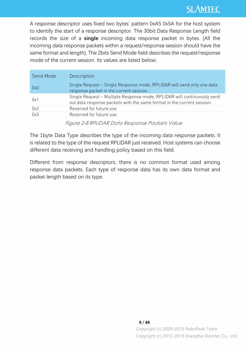
A response descriptor uses fixed two bytes’ pattern 0xA5 0x5A for the host system
to identify the start of a response descriptor. The 30bit Data Response Length field
records the size of a single incoming data response packet in bytes. (All the
incoming data response packets within a request/response session should have the
same format and length). The 2bits Send Mode field describes the request/response
mode of the current session. Its values are listed below:
0x0 Single Request – Single Response mode, RPLIDAR will send only one data
response packet in the current session.
0x1 Single Request – Multiple Response mode, RPLIDAR will continuously send
out data response packets with the same format in the current session.
0x2 Reserved for future use
0x3 Reserved for future use
Figure 2-8 RPLIDAR Data Response Packets Value
The 1byte Data Type describes the type of the incoming data response packets. It
is related to the type of the request RPLIDAR just received. Host systems can choose
different data receiving and handling policy based on this field.
Different from response descriptors, there is no common format used among
response data packets. Each type of response data has its own data format and
packet length based on its type.
Send Mode Description
10 / 49
Copyright (c) 2009-2013 RoboPeak Team
Copyright (c) 2013-2019 Shanghai Slamtec Co., Ltd.
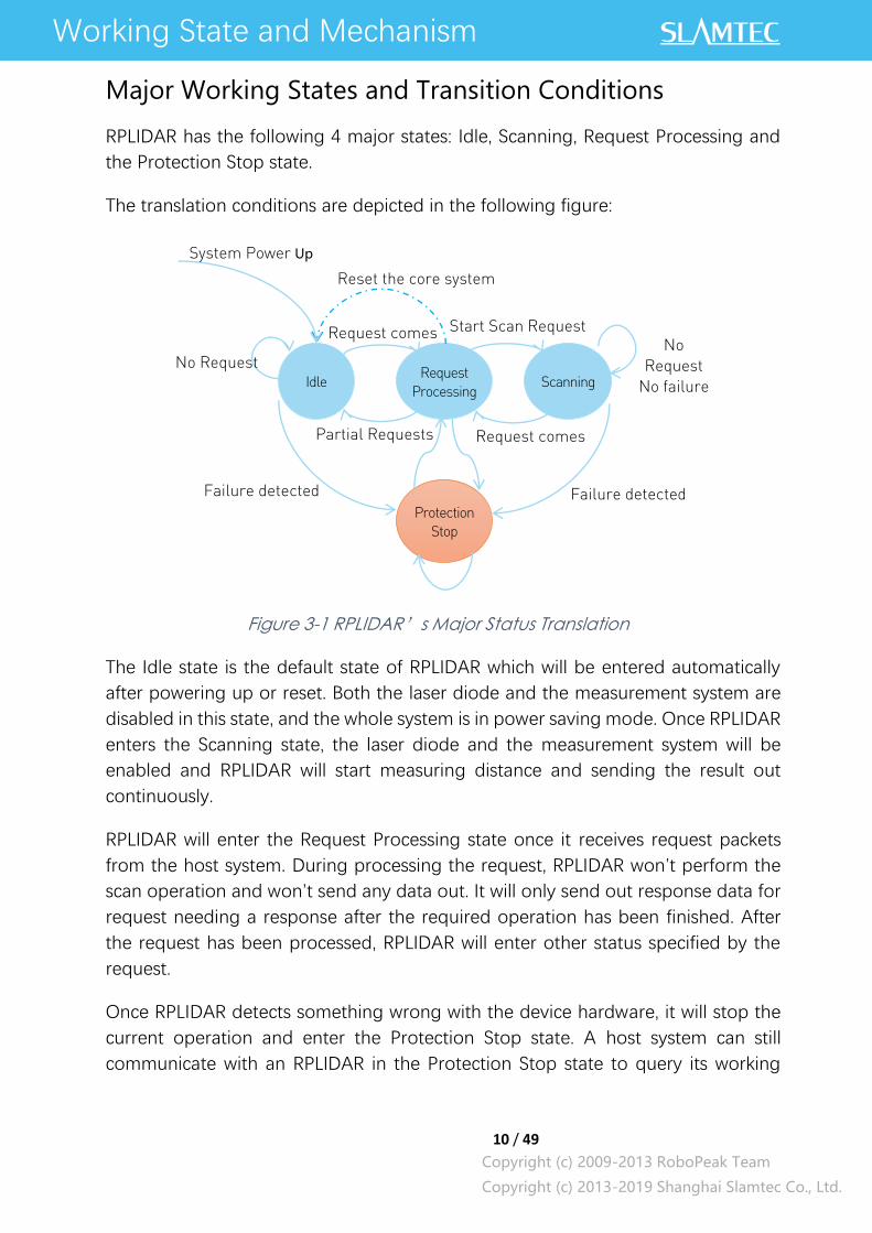
Major Working States and Transition Conditions
RPLIDAR has the following 4 major states: Idle, Scanning, Request Processing and
the Protection Stop state.
The translation conditions are depicted in the following figure:
Figure 3-1 RPLIDAR’s Major Status Translation
The Idle state is the default state of RPLIDAR which will be entered automatically
after powering up or reset. Both the laser diode and the measurement system are
disabled in this state, and the whole system is in power saving mode. Once RPLIDAR
enters the Scanning state, the laser diode and the measurement system will be
enabled and RPLIDAR will start measuring distance and sending the result out
continuously.
RPLIDAR will enter the Request Processing state once it receives request packets
from the host system. During processing the request, RPLIDAR won’t perform the
scan operation and won’t send any data out. It will only send out response data for
request needing a response after the required operation has been finished. After
the request has been processed, RPLIDAR will enter other status specified by the
request.
Once RPLIDAR detects something wrong with the device hardware, it will stop the
current operation and enter the Protection Stop state. A host system can still
communicate with an RPLIDAR in the Protection Stop state to query its working
Working State and Mechanism
Idle Scanning Request
Processing
Protection
Stop
Reset the core system
No Request No
Request
No failure
System Power Up
Request comes
Partial Requests
Start Scan Request
Request comes
Failure detected
Failure detected
11 / 49
Copyright (c) 2009-2013 RoboPeak Team
Copyright (c) 2013-2019 Shanghai Slamtec Co., Ltd.
status. But the host system cannot ask the RPLIDAR to perform scan operations
unless the host system send a Reset request to reboot the RPLIDAR core system.
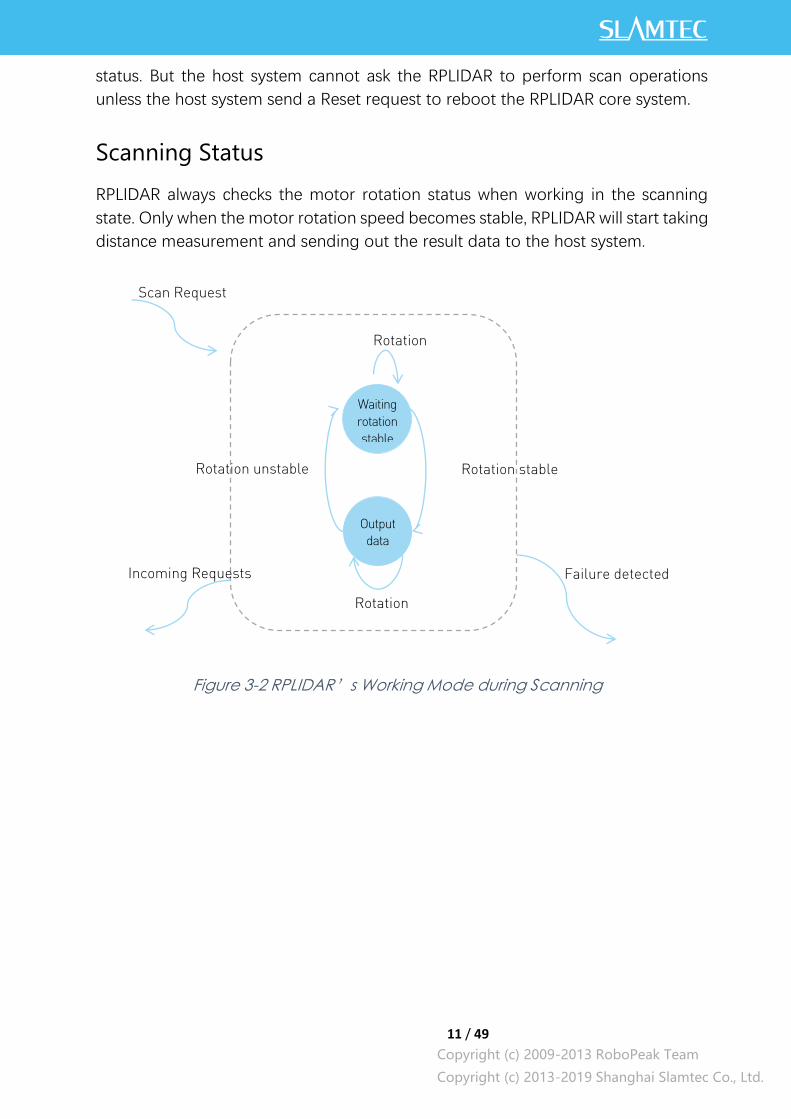
Scanning Status
RPLIDAR always checks the motor rotation status when working in the scanning
state. Only when the motor rotation speed becomes stable, RPLIDAR will start taking
distance measurement and sending out the result data to the host system.
Figure 3-2 RPLIDAR’s Working Mode during Scanning
Output
data
Waiting
rotation
stable
Scan Request
Rotation
stable
Rotation stable
Rotation unstable
Incoming Requests
Failure detected
Rotation
unstable

12 / 49
Copyright (c) 2009-2013 RoboPeak Team
Copyright (c) 2013-2019 Shanghai Slamtec Co., Ltd.
Scan Mode and Measurement Frequency
A new concept called ‘scan mode’ is introduced since firmware version 1.24.
RPLIDAR’s following performance may differ in different scan modes:
Measurement frequency
Max measurement distance
Sensitivity of detection
Environment light elimination
Different model of RPLIDAR support different set of scan modes. Each of them is
optimized for specified work environment. Some typical scan modes are defined as
below:
Scan
Mode
Name
Description Max Sample
Rate (sps)
Max
Distance Extra Features
Legacy Traditional
Mode
2000 for A1/A2,
4000 for A3 16 m
Reflection rate
Express Traditional
Express Mode
4000 for A1/A2,
8000 for A3
Boost Performance
Priority Mode
8000 for A1/A2,
16000 for A3
28m
Optimized for sample rate
Sensitivity Sensitivity
Priority Mode
n/a for A1/A2,
16000 for A3
Optimized for longer range,
better sensitivity, but weak
environment light elimination.
Stability Stability
Priority Mode
n/a for A1/A2,
16000 for A3
Optimized for environment light
elimination performance, but
shorter range and lower sample
rate.
Figure 3-3 Typical scan modes of RPLIDAR
A new command GET_LIDAR_CONF has been added to help host system to
enumerate all scan modes supported by a LIDAR device, as well as the performance
parameters of each scan mode. This command can also be used to get “Typical Scan
Mode” of a LIDAR, which is the recommend work mode for particular LIDAR model
by Slamtec.
To avoid problems, SLAMTEC highly recommends users manipulate work modes of
an RPLIDAR via the RPLIDAR Public SDKs.
Request and Response Data
13 / 49
Copyright (c) 2009-2013 RoboPeak Team
Copyright (c) 2013-2019 Shanghai Slamtec Co., Ltd.
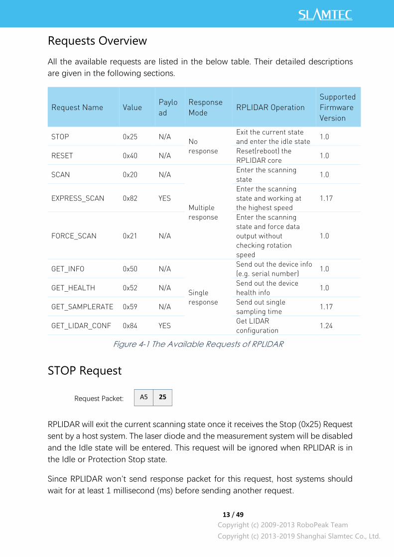
Requests Overview
All the available requests are listed in the below table. Their detailed descriptions
are given in the following sections.
Request Name Value Paylo
ad
Response
Mode RPLIDAR Operation
Supported
Firmware
Version
STOP 0x25 N/A No
response
Exit the current state
and enter the idle state 1.0
RESET 0x40 N/A Reset(reboot) the
RPLIDAR core 1.0
SCAN 0x20 N/A
Multiple
response
Enter the scanning
state 1.0
EXPRESS_SCAN 0x82 YES
Enter the scanning
state and working at
the highest speed
1.17
FORCE_SCAN 0x21 N/A
Enter the scanning
state and force data
output without
checking rotation
speed
1.0
GET_INFO 0x50 N/A
Single
response
Send out the device info
(e.g. serial number) 1.0
GET_HEALTH 0x52 N/A Send out the device
health info 1.0
GET_SAMPLERATE 0x59 N/A Send out single
sampling time 1.17
GET_LIDAR_CONF 0x84 YES Get LIDAR
configuration 1.24
Figure 4-1 The Available Requests of RPLIDAR
STOP Request
RPLIDAR will exit the current scanning state once it receives the Stop (0x25) Request
sent by a host system. The laser diode and the measurement system will be disabled
and the Idle state will be entered. This request will be ignored when RPLIDAR is in
the Idle or Protection Stop state.
Since RPLIDAR won’t send response packet for this request, host systems should
wait for at least 1 millisecond (ms) before sending another request.
A5 25 Request Packet:

14 / 49
Copyright (c) 2009-2013 RoboPeak Team
Copyright (c) 2013-2019 Shanghai Slamtec Co., Ltd.
Figure 4-2 The Timing Sequence of a STOP Request
RPLIDAR Core Reset(RESET) Request
Host systems can make RPLIDAR core to reset (reboot) itself by sending this request.
A reset operation will make RPLIDAR revert to a similar state as it has just been
powered up. This request is useful when RPLIDAR has entered the Protection Stop
state. After a core reset, RPLIDAR will return to the idle state which will accept the
start scan request again.
Since RPLIDAR won’t send response packet for this request, host systems should
wait for at least 2 milliseconds (ms) before sending another request.
Figure 4-3 The Timing Sequence of a RESET Request
Start Scan(SCAN) Request and Response
Note: RPLIDAR device models support 4khz or higher sampling rate will lower the sampling
rate when processing this request. Please use EXPRESS_SCAN for the best performance.
This command supports Legacy scan mode only.
RP
LID
AR
Host S
ystem
A5 25 A5 …
≥1m
s
Next request
A5 40 Request Packet:
RP
LID
AR
Host S
ystem
统
A5 40 A5 …
≥2m
s
Next Request
15 / 49
Copyright (c) 2009-2013 RoboPeak Team
Copyright (c) 2013-2019 Shanghai Slamtec Co., Ltd.
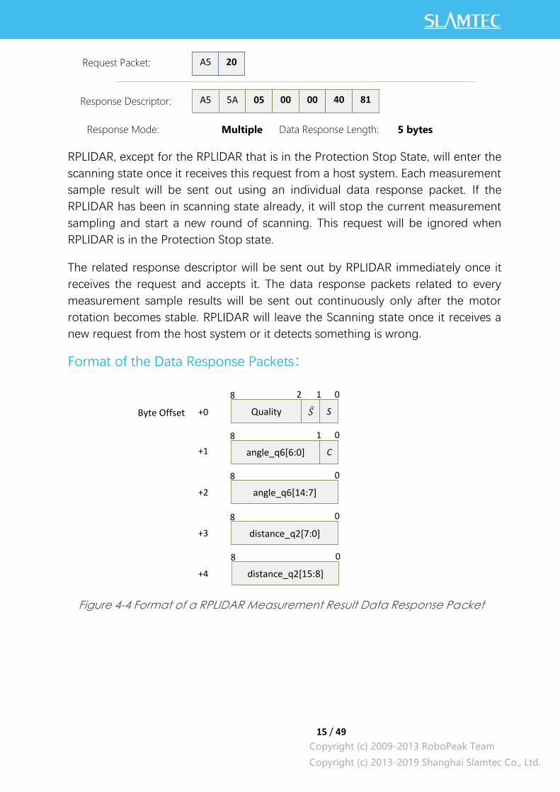
RPLIDAR, except for the RPLIDAR that is in the Protection Stop State, will enter the
scanning state once it receives this request from a host system. Each measurement
sample result will be sent out using an individual data response packet. If the
RPLIDAR has been in scanning state already, it will stop the current measurement
sampling and start a new round of scanning. This request will be ignored when
RPLIDAR is in the Protection Stop state.
The related response descriptor will be sent out by RPLIDAR immediately once it
receives the request and accepts it. The data response packets related to every
measurement sample results will be sent out continuously only after the motor
rotation becomes stable. RPLIDAR will leave the Scanning state once it receives a
new request from the host system or it detects something is wrong.
Format of the Data Response Packets:
Figure 4-4 Format of a RPLIDAR Measurement Result Data Response Packet
A5 20 Request Packet:
A5 5A Response Descriptor:
05 00 00 40 81
Response Mode: Multiple Data Response Length: 5 bytes
Quality S 𝑆ҧ
8 2 1 0
angle_q6[6:0] C
8 1 0
angle_q6[14:7]
8 0
distance_q2[7:0]
8 0
distance_q2[15:8]
8 0
+0
+1
+2
+3
+4
Byte Offset

16 / 49
Copyright (c) 2009-2013 RoboPeak Team
Copyright (c) 2013-2019 Shanghai Slamtec Co., Ltd.
RPLIDAR encapsulates each measurement sample into a data response packet with
the format showed in the above figure and send the packet out. The descriptions of
every field within the packet are listed in the following table:
S Start flag bit of a new scan
When S is set to 1, the current
and incoming packets belong to a
new 360o scan.
�̅� Inversed start flag bit, always has 𝑆ҧ = ! 𝑆
Can be used as a data check bit.
C Check bit, constantly set to 1 Can be used as a data check bit.
quality Quality of the current measurement
sample
Related the reflected laser pulse
strength.
angle_q6
The measurement heading angle
related to RPLIDAR’s heading. In
degree unit, [0-360)
Stored using fix point number.
Refer to the below figure for
details.
Actual heading =
angle_q6/64.0 Degree
distance_q2
Measured object distance related to
RPLIDAR’s rotation center.
In millimeter (mm) unit.
Represents using fix point. Set to 0
when the measurement is invalid.
Refer to the below figure for
details.
Actual Distance =
distance_q2/4.0 mm
Figure 4-5 Field Definition of a RPLIDAR Measurement Result Data Response
Packet
The geometric definition of the included angle and distance value is shown as below:
Figure 4-6 Angle and Distance Value Geometric Definition for RPLIDAR A1
series
Field Name Description Examples / Notes
θ [0,360)
17 / 49
Copyright (c) 2009-2013 RoboPeak Team
Copyright (c) 2013-2019 Shanghai Slamtec Co., Ltd.
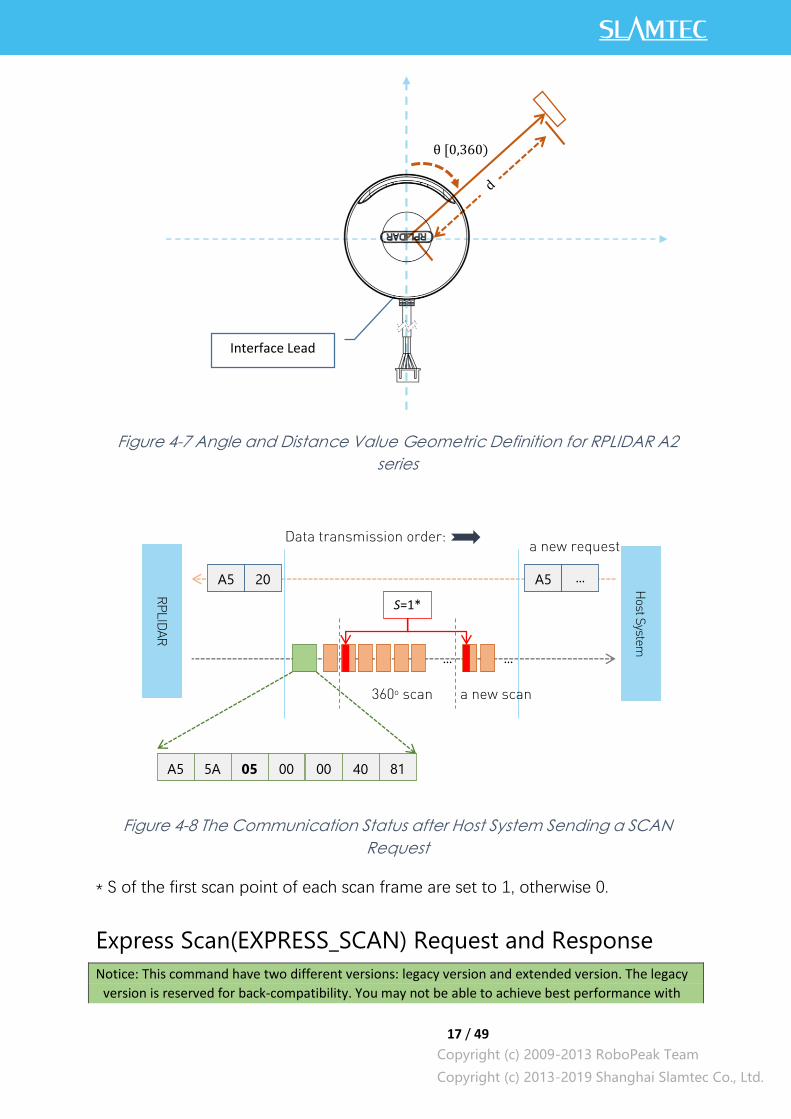
Figure 4-7 Angle and Distance Value Geometric Definition for RPLIDAR A2
series
Figure 4-8 The Communication Status after Host System Sending a SCAN
Request
* S of the first scan point of each scan frame are set to 1, otherwise 0.
Express Scan(EXPRESS_SCAN) Request and Response
Notice: This command have two different versions: legacy version and extended version. The legacy
version is reserved for back-compatibility. You may not be able to achieve best performance with
θ [0,360)
Interface Lead
RP
LID
AR
Host S
ystem
A5 20 A5 …
a new request Data transmission order:
… …
S=1*
360o scan a new scan
A5 5A 05 00 00 40 81

18 / 49
Copyright (c) 2009-2013 RoboPeak Team
Copyright (c) 2013-2019 Shanghai Slamtec Co., Ltd.
legacy version. Please use extended version for scan modes sample more than 4000 times per
second and max distance of which exceeds 16m.
RPLIDAR Public SDK has been updated to hide the complexity and variety of the protocol. It selects
scan mode automatically according to user’s requirement, and is back-compatible to RPLIDARs with
firmware prior to 1.24.
Legacy Version
Extended Version1
Dense Version
1 Lagacy Vesion and Dense Version have same request packet, their response depend on RPLIDAR. The field ‘M’ denotes the expected scan mode id, while ‘C’ is the checksum of this request.
A5 82
A5 5A 54 00 00 40 82
84 bytes
05 00 00 00 00 00 22 Request Packet:
Response Descriptor:
Response Mode:
Multiple
Data Response Length:
A5 82
A5 5A 84 00 00 40 84
132 bytes
05 M 00 00 00 00 C Request Packet:
Response Descriptor:
Response Mode:
Multiple
Data Response Length:
A5 82
A5 5A 54 00 00 40 85
84 bytes
05 00 00 00 00 00 22 Request Packet:
Response Descriptor:
Response Mode:
Multiple
Data Response Length:
19 / 49
Copyright (c) 2009-2013 RoboPeak Team
Copyright (c) 2013-2019 Shanghai Slamtec Co., Ltd.
RPLIDAR will enter the measurement sampling mode once it receives the express
scan(EXPRESS_SCAN) request. Different from the scan(SCAN) request, this request
will make RPLIDAR work at the sampling rate as high as it can be. For LIDARs support
sampling more than 4000 times per second, the host system should use
GET_LIDAR_CONF command to get “Typical Scan Mode”, and use this command to
make LIDAR work under its best performance and output measurement sample data
accordingly.
The host system can use GET_LIDAR_CONF to get all scan modes, as well as
performance parameters, such as sample frequency, measurement range and etc.
The sample duration of standard and express mode could also be fetched via
command GET_SAMPLERATE.
RPLIDAR uses the same state machine and processing logic for this request as the
one of the scan(SCAN) request, but uses the different response format.
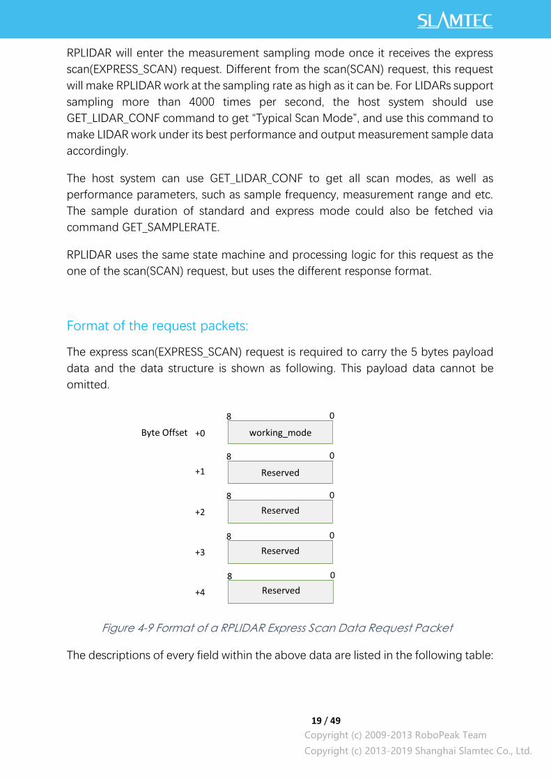
Format of the request packets:
The express scan(EXPRESS_SCAN) request is required to carry the 5 bytes payload
data and the data structure is shown as following. This payload data cannot be
omitted.
Figure 4-9 Format of a RPLIDAR Express Scan Data Request Packet
The descriptions of every field within the above data are listed in the following table:
working_mode
8 0
Reserved
8 0
Reserved
8 0
Reserved
8 0
Reserved
8 0
+0
+1
+2
+3
+4
Byte Offset
20 / 49
Copyright (c) 2009-2013 RoboPeak Team
Copyright (c) 2013-2019 Shanghai Slamtec Co., Ltd.
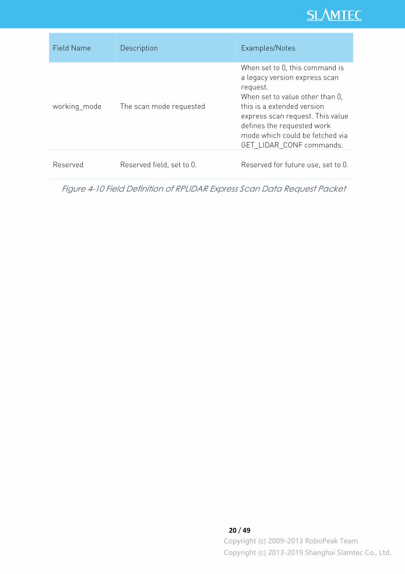
Field Name Description Examples/Notes
working_mode The scan mode requested
When set to 0, this command is
a legacy version express scan
request.
When set to value other than 0,
this is a extended version
express scan request. This value
defines the requested work
mode which could be fetched via
GET_LIDAR_CONF commands.
Reserved Reserved field, set to 0. Reserved for future use, set to 0.
Figure 4-10 Field Definition of RPLIDAR Express Scan Data Request Packet
21 / 49
Copyright (c) 2009-2013 RoboPeak Team
Copyright (c) 2013-2019 Shanghai Slamtec Co., Ltd.
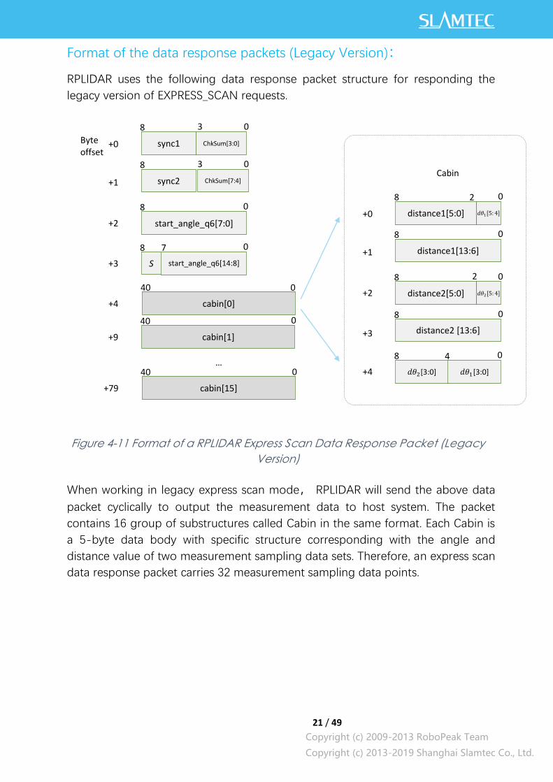
Format of the data response packets (Legacy Version):
RPLIDAR uses the following data response packet structure for responding the
legacy version of EXPRESS_SCAN requests.
Figure 4-11 Format of a RPLIDAR Express Scan Data Response Packet (Legacy
Version)
When working in legacy express scan mode, RPLIDAR will send the above data
packet cyclically to output the measurement data to host system. The packet
contains 16 group of substructures called Cabin in the same format. Each Cabin is
a 5-byte data body with specific structure corresponding with the angle and
distance value of two measurement sampling data sets. Therefore, an express scan
data response packet carries 32 measurement sampling data points.
ChkSum[7:4]
sync1 ChkSum[3:0]
8 3 0
start_angle_q6[7:0]
8 0
start_angle_q6[14:8]
8 0
cabin[0]
40 0
+0
+1
+2
+3
+4
Byte offset
sync2
8 3 0
S
7
cabin[1]
40 0
+9
cabin[15]
40 0
+79
…
𝑑𝜃1[5: 4]
8 2 0
+0
+1
+2
+3
distance1[13:6]
8 0
𝑑𝜃2[3:0]
8 0
+4
distance1[5:0]
𝑑𝜃2[5: 4]
8 2 0
distance2 [13:6]
8 0
distance2[5:0]
𝑑𝜃1[3:0]
4
Cabin
22 / 49
Copyright (c) 2009-2013 RoboPeak Team
Copyright (c) 2013-2019 Shanghai Slamtec Co., Ltd.
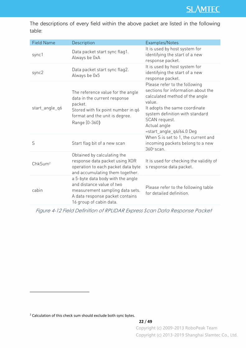
The descriptions of every field within the above packet are listed in the following
table:
Field Name Description Examples/Notes
sync1 Data packet start sync flag1.
Always be 0xA
It is used by host system for
identifying the start of a new
response packet.
sync2 Data packet start sync flag2.
Always be 0x5
It is used by host system for
identifying the start of a new
response packet.
start_angle_q6
The reference value for the angle
data in the current response
packet.
Stored with fix point number in q6
format and the unit is degree.
Range [0-360)
Please refer to the following
sections for information about the
calculated method of the angle
value.
It adopts the same coordinate
system definition with standard
SCAN request.
Actual angle
=start_angle_q6/64.0 Deg
S Start flag bit of a new scan
When S is set to 1, the current and
incoming packets belong to a new
360o scan.
ChkSum2
Obtained by calculating the
response data packet using XOR
operation to each packet data byte
and accumulating them together.
It is used for checking the validity of
s response data packet.
cabin
a 5-byte data body with the angle
and distance value of two
measurement sampling data sets.
A data response packet contains
16 group of cabin data.
Please refer to the following table
for detailed definition.
Figure 4-12 Field Definition of RPLIDAR Express Scan Data Response Packet
2 Calculation of this check sum should exclude both sync bytes.

23 / 49
Copyright (c) 2009-2013 RoboPeak Team
Copyright (c) 2013-2019 Shanghai Slamtec Co., Ltd.
The following table describes the filed definition of the Cabin data.
Field Definition Description Examples/Notes
distance1
distance2
The distance data for the first and
second measurement sampling.
The unit is millimeter(mm)
When the value is 0, the matched
sampling point is invalid.
The first sampling time is
before the second.
𝑑𝜃1 𝑑𝜃2
The angular compensation value
for the first and second
measurement sampling.
It uses fix point number in q3
format and the unit is degree. The
top digit is sign bit.
Please refer to the following
sections for how to calculate
the included angle value of
every measurement sampling
point.
Figure 4-13 Field Definition of RPLIDAR Express Scan Cabin Data Response
Packet
The following figure describes the communication status after the host system
sending out the express scan request.3
Figure 4-14 The Communication Status Sending Out the Express Scan Request
3 Only the first cabin of the first scan after start scan command will be marked as S=1, all other cabins are marked as S=0. A new scan starts at a measurement point whose raw angle is smaller than previous one.
RP
LID
AR
Host system
A5 A5 …
A new request Data transmission order:
… …
S=0
360° scan A new scan
A5 5A 54 00 00 40 82
82 05 …
S=1
24 / 49
Copyright (c) 2009-2013 RoboPeak Team
Copyright (c) 2013-2019 Shanghai Slamtec Co., Ltd.
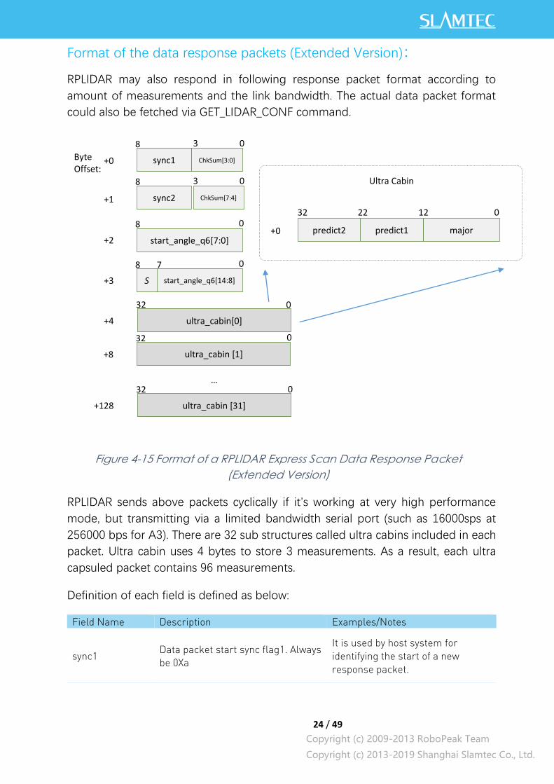
Format of the data response packets (Extended Version):
RPLIDAR may also respond in following response packet format according to
amount of measurements and the link bandwidth. The actual data packet format
could also be fetched via GET_LIDAR_CONF command.
Figure 4-15 Format of a RPLIDAR Express Scan Data Response Packet
(Extended Version)
RPLIDAR sends above packets cyclically if it’s working at very high performance
mode, but transmitting via a limited bandwidth serial port (such as 16000sps at
256000 bps for A3). There are 32 sub structures called ultra cabins included in each
packet. Ultra cabin uses 4 bytes to store 3 measurements. As a result, each ultra
capsuled packet contains 96 measurements.
Definition of each field is defined as below:
Field Name Description Examples/Notes
sync1 Data packet start sync flag1. Always
be 0Xa
It is used by host system for
identifying the start of a new
response packet.
ChkSum[7:4]
sync1 ChkSum[3:0]
8 3 0
start_angle_q6[7:0]
8 0
start_angle_q6[14:8]
8 0
ultra_cabin[0]
32 0
+0
+1
+2
+3
+4
Byte Offset:
sync2
8 3 0
S
7
ultra_cabin [1]
32 0
+8
ultra_cabin [31]
32 0
+128
…
12 0
+0 major
Ultra Cabin
predict1 predict2
22 32
25 / 49
Copyright (c) 2009-2013 RoboPeak Team
Copyright (c) 2013-2019 Shanghai Slamtec Co., Ltd.
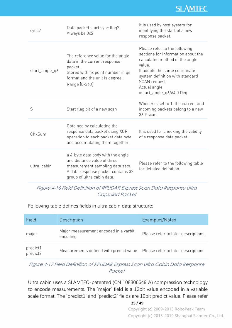
sync2 Data packet start sync flag2.
Always be 0x5
It is used by host system for
identifying the start of a new
response packet.
start_angle_q6
The reference value for the angle
data in the current response
packet.
Stored with fix point number in q6
format and the unit is degree.
Range [0-360)
Please refer to the following
sections for information about the
calculated method of the angle
value.
It adopts the same coordinate
system definition with standard
SCAN request.
Actual angle
=start_angle_q6/64.0 Deg
S Start flag bit of a new scan
When S is set to 1, the current and
incoming packets belong to a new
360o scan.
ChkSum
Obtained by calculating the
response data packet using XOR
operation to each packet data byte
and accumulating them together.
It is used for checking the validity
of s response data packet.
ultra_cabin
a 4-byte data body with the angle
and distance value of three
measurement sampling data sets.
A data response packet contains 32
group of ultra cabin data.
Please refer to the following table
for detailed definition.
Figure 4-16 Field Definition of RPLIDAR Express Scan Data Response Ultra
Capsuled Packet
Following table defines fields in ultra cabin data structure:
Field Description Examples/Notes
major Major measurement encoded in a varbit
encoding Please refer to later descriptions.
predict1
predict2 Measurements defined with predict value Please refer to later descriptions
Figure 4-17 Field Definition of RPLIDAR Express Scan Ultra Cabin Data Response
Packet
Ultra cabin uses a SLAMTEC-patented (CN 108306649 A) compression technology
to encode measurements. The `major` field is a 12bit value encoded in a variable
scale format. The `predict1` and `predict2` fields are 10bit predict value. Please refer
26 / 49
Copyright (c) 2009-2013 RoboPeak Team
Copyright (c) 2013-2019 Shanghai Slamtec Co., Ltd.
to the source of our public SDK or related patent for technical details. Using open-
sourced SDK is preferred, comparing to implement decoder on your own.
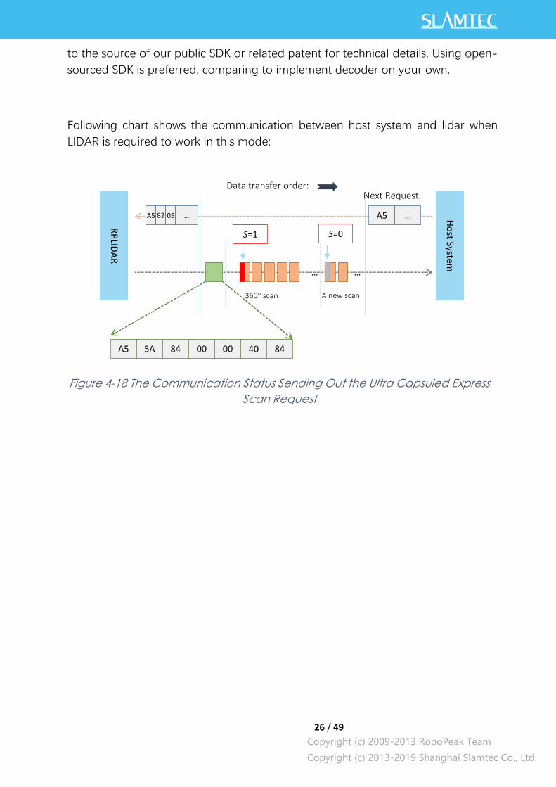
Following chart shows the communication between host system and lidar when
LIDAR is required to work in this mode:
Figure 4-18 The Communication Status Sending Out the Ultra Capsuled Express
Scan Request
RP
LIDA
R
Ho
st System
A5 A5 …
Next Request Data transfer order:
… …
S=0
360° scan A new scan
A5 5A 84 00 00 40 84
82 05 …
S=1

27 / 49
Copyright (c) 2009-2013 RoboPeak Team
Copyright (c) 2013-2019 Shanghai Slamtec Co., Ltd.
Format of the data response packets (Dense Version):
RPLIDAR may respond in following response packet format according to amount of
measurements and the link bandwidth. The actual data packet format could also be
fetched via GET_LIDAR_CONF command.
Figure 4-19 Format of a RPLIDAR Express Scan Data Response Packet (Dense
Version)
If RPLIDAR had received the request to work in dense scan mode, it would cyclically
output the measurement data to host system by the above data packet. The packet
contains 40 group of substructures also called Cabin in the same format. Each Cabin
is a 2-byte data body corresponding with a measurement sampling data. Therefore,
a dense scan data response packet contains 40 measurement sampling data points.
The following table describes the filed definition of the Dense Capsule data.
Field Name Description Examples/Notes
sync1 Data packet start sync flag1.
Always be 0xA
It is used by host system for
identifying the start of a new
response packet.
sync2 Data packet start sync flag2.
Always be 0x5
It is used by host system for
identifying the start of a new
response packet.
ChkSum[7:4]
sync1 ChkSum[3:0]
8 3 0
start_angle_q6[7:0]
8 0
start_angle_q6[14:8]
8 0
cabin[0]
16 0
+0
+1
+2
+3
+4
Byte Offset:
sync2
8 3 0
S
7
cabin[1]
16 0
+6
cabin[40]
16 0
+82
…
8 0
+0 distance[15:0]
Cabin
28 / 49
Copyright (c) 2009-2013 RoboPeak Team
Copyright (c) 2013-2019 Shanghai Slamtec Co., Ltd.
start_angle_q6
The reference value for the angle
data in the current response
packet.
Stored with fix point number in q6
format and the unit is degree.
Range [0-360)
Please refer to the following
sections for information about the
calculated method of the angle
value.
It adopts the same coordinate
system definition with standard
SCAN request.
Actual angle
=start_angle_q6/64.0 Deg
S Start flag bit of a new scan
When S is set to 1, the current and
incoming packets belong to a new
360o scan.
ChkSum
Obtained by calculating the
response data packet using XOR
operation to each packet data byte
and accumulating them together.
It is used for checking the validity of
s response data packet.
cabin
a 2-byte data body with the angle
and distance value of two
measurement sampling data sets.
A data response packet contains
40 groups of cabin data.
Please refer to the following table
for detailed definition.
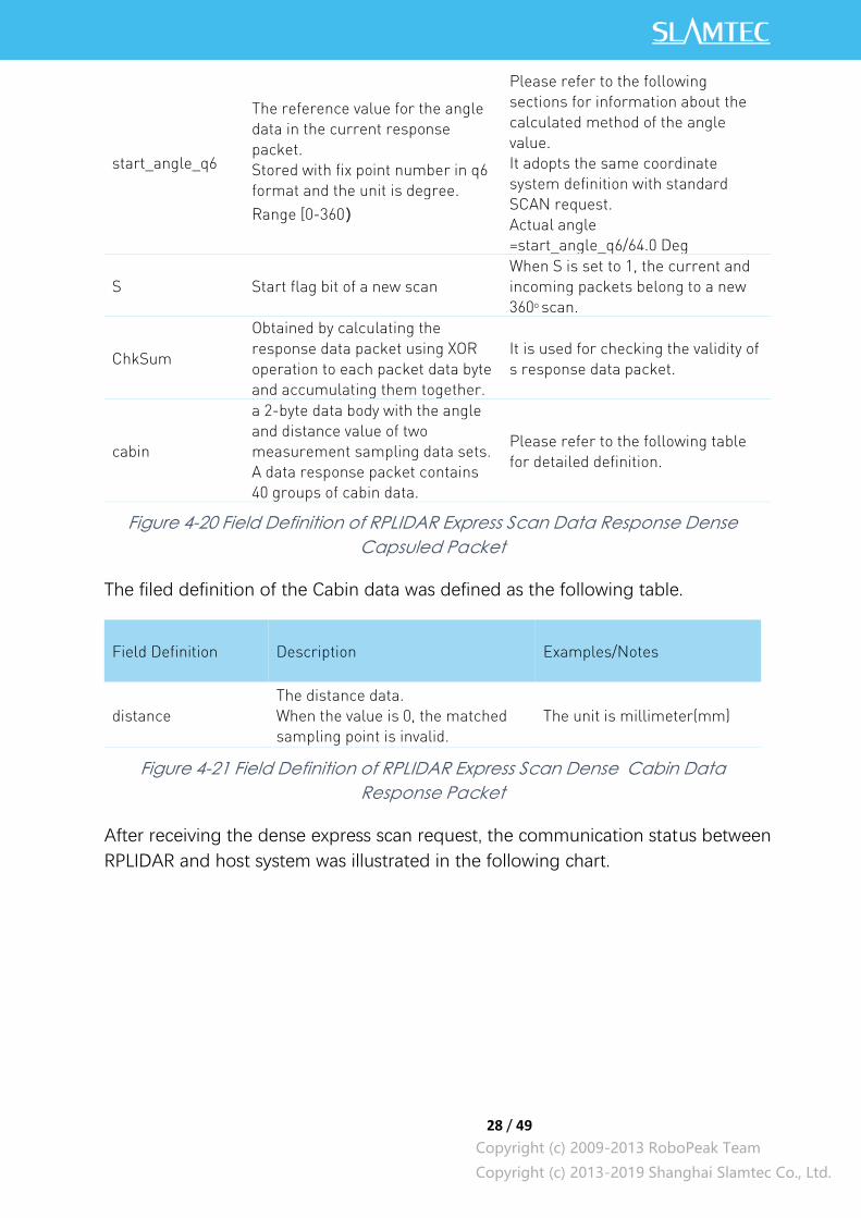
Figure 4-20 Field Definition of RPLIDAR Express Scan Data Response Dense
Capsuled Packet
The filed definition of the Cabin data was defined as the following table.
Field Definition Description Examples/Notes
distance
The distance data.
When the value is 0, the matched
sampling point is invalid.
The unit is millimeter(mm)
Figure 4-21 Field Definition of RPLIDAR Express Scan Dense Cabin Data
Response Packet
After receiving the dense express scan request, the communication status between
RPLIDAR and host system was illustrated in the following chart.
29 / 49
Copyright (c) 2009-2013 RoboPeak Team
Copyright (c) 2013-2019 Shanghai Slamtec Co., Ltd.
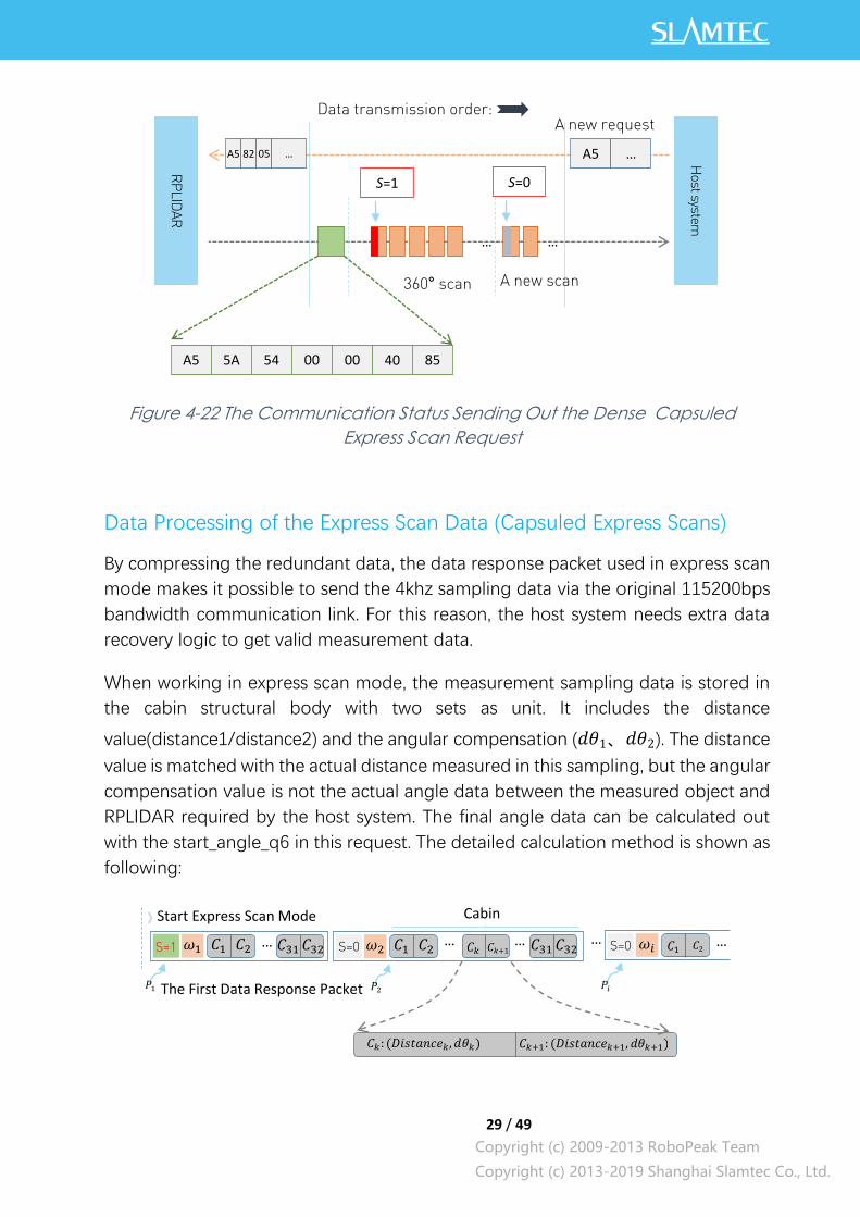
Figure 4-22 The Communication Status Sending Out the Dense Capsuled
Express Scan Request
Data Processing of the Express Scan Data (Capsuled Express Scans)
By compressing the redundant data, the data response packet used in express scan
mode makes it possible to send the 4khz sampling data via the original 115200bps
bandwidth communication link. For this reason, the host system needs extra data
recovery logic to get valid measurement data.
When working in express scan mode, the measurement sampling data is stored in
the cabin structural body with two sets as unit. It includes the distance
value(distance1/distance2) and the angular compensation (𝑑𝜃1、𝑑𝜃2). The distance
value is matched with the actual distance measured in this sampling, but the angular
compensation value is not the actual angle data between the measured object and
RPLIDAR required by the host system. The final angle data can be calculated out
with the start_angle_q6 in this request. The detailed calculation method is shown as
following:
RP
LID
AR
Host system
A5 A5 …
A new request Data transmission order:
… …
S=0
360° scan A new scan
A5 5A 54 00 00 40 85
82 05 …
S=1
Start Express Scan Mode
S=0 𝜔2 𝐶2 𝐶1 𝐶𝑘+1 𝐶𝑘 𝐶32 𝐶31 … S=1 𝜔1 𝐶2 𝐶1 𝐶32 𝐶31 … S=0 𝜔𝑖 𝐶2 𝐶1 … …
The First Data Response Packet
Cabin
𝑃1 𝑃2 𝑃𝑖
𝐶𝑘: (𝐷𝑖𝑠𝑡𝑎𝑛𝑐𝑒𝑘, 𝑑𝜃𝑘) 𝐶𝑘+1: (𝐷𝑖𝑠𝑡𝑎𝑛𝑐𝑒𝑘+1, 𝑑𝜃𝑘+1)
…
30 / 49
Copyright (c) 2009-2013 RoboPeak Team
Copyright (c) 2013-2019 Shanghai Slamtec Co., Ltd.
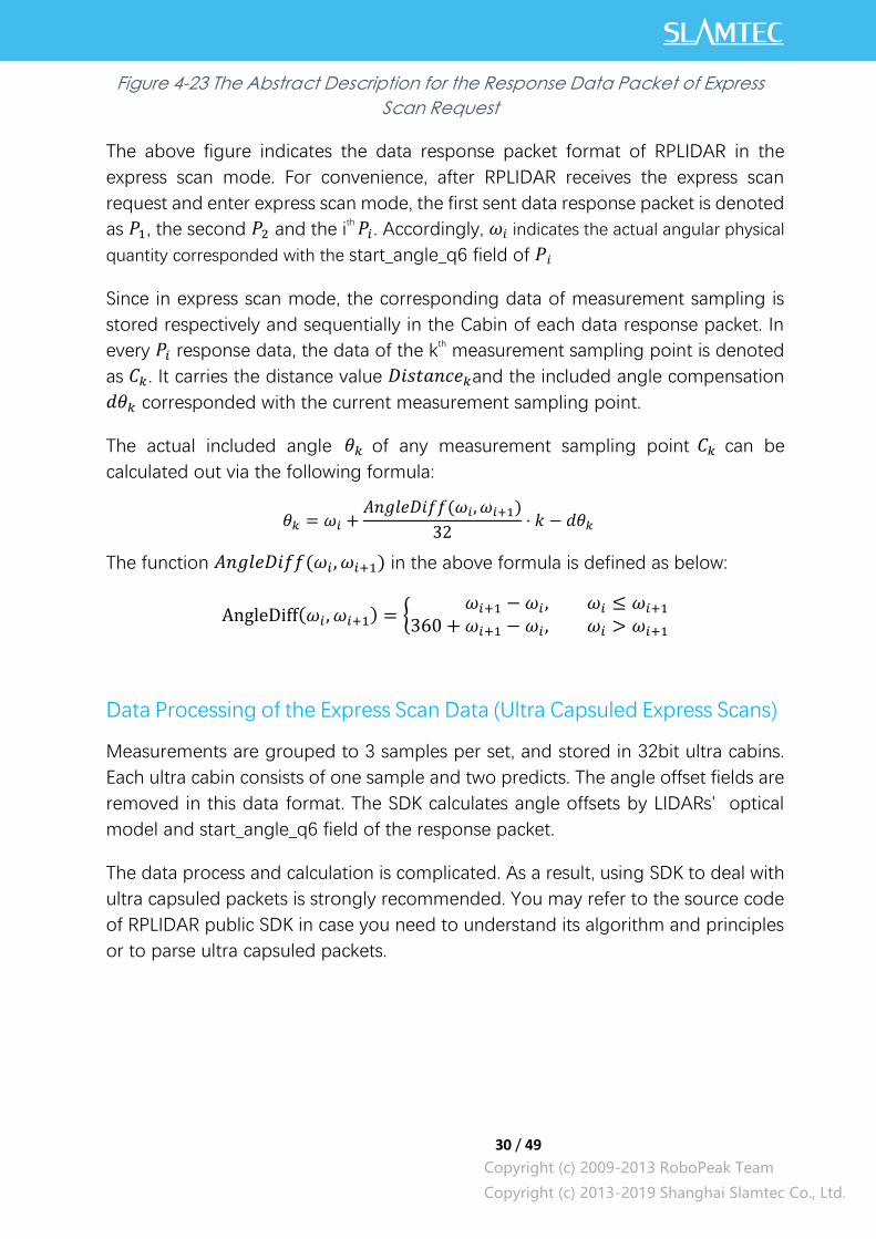
Figure 4-23 The Abstract Description for the Response Data Packet of Express
Scan Request
The above figure indicates the data response packet format of RPLIDAR in the
express scan mode. For convenience, after RPLIDAR receives the express scan
request and enter express scan mode, the first sent data response packet is denoted
as 𝑃1, the second 𝑃2 and the ith 𝑃𝑖 . Accordingly, 𝜔𝑖 indicates the actual angular physical
quantity corresponded with the start_angle_q6 field of 𝑃𝑖
Since in express scan mode, the corresponding data of measurement sampling is
stored respectively and sequentially in the Cabin of each data response packet. In
every 𝑃𝑖 response data, the data of the kth measurement sampling point is denoted
as 𝐶𝑘. It carries the distance value 𝐷𝑖𝑠𝑡𝑎𝑛𝑐𝑒𝑘and the included angle compensation
𝑑𝜃𝑘 corresponded with the current measurement sampling point.
The actual included angle 𝜃𝑘 of any measurement sampling point 𝐶𝑘 can be
calculated out via the following formula:
𝜃𝑘 = 𝜔𝑖 +𝐴𝑛𝑔𝑙𝑒𝐷𝑖𝑓𝑓(𝜔𝑖, 𝜔𝑖+1)
32⋅ 𝑘 − 𝑑𝜃𝑘
The function 𝐴𝑛𝑔𝑙𝑒𝐷𝑖𝑓𝑓(𝜔𝑖 , 𝜔𝑖+1) in the above formula is defined as below:
AngleDiff(𝜔𝑖 , 𝜔𝑖+1) = {𝜔𝑖+1 − 𝜔𝑖 , 𝜔𝑖 ≤ 𝜔𝑖+1
360 + 𝜔𝑖+1 − 𝜔𝑖 , 𝜔𝑖 > 𝜔𝑖+1
Data Processing of the Express Scan Data (Ultra Capsuled Express Scans)
Measurements are grouped to 3 samples per set, and stored in 32bit ultra cabins.
Each ultra cabin consists of one sample and two predicts. The angle offset fields are
removed in this data format. The SDK calculates angle offsets by LIDARs’ optical
model and start_angle_q6 field of the response packet.
The data process and calculation is complicated. As a result, using SDK to deal with
ultra capsuled packets is strongly recommended. You may refer to the source code
of RPLIDAR public SDK in case you need to understand its algorithm and principles
or to parse ultra capsuled packets.
31 / 49
Copyright (c) 2009-2013 RoboPeak Team
Copyright (c) 2013-2019 Shanghai Slamtec Co., Ltd.
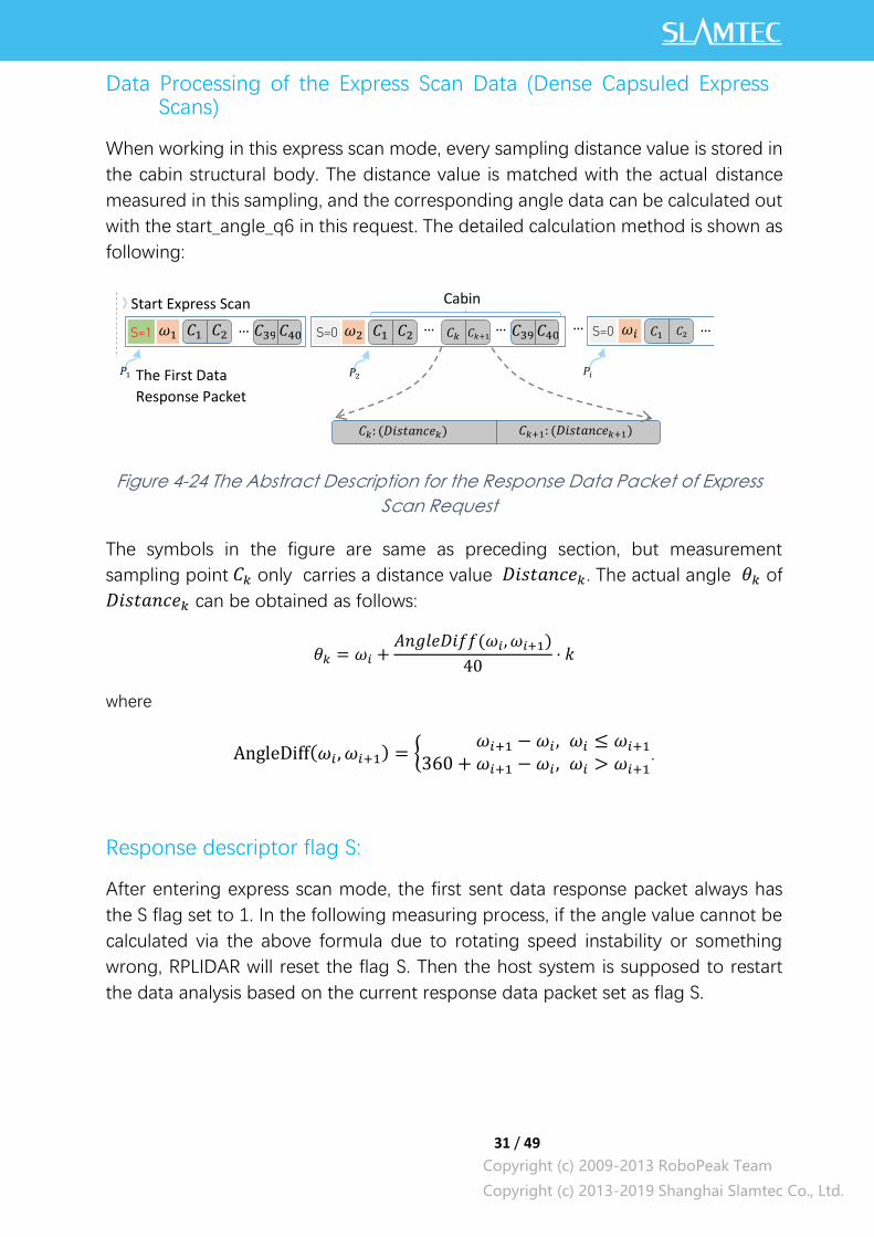
Data Processing of the Express Scan Data (Dense Capsuled Express Scans)
When working in this express scan mode, every sampling distance value is stored in
the cabin structural body. The distance value is matched with the actual distance
measured in this sampling, and the corresponding angle data can be calculated out
with the start_angle_q6 in this request. The detailed calculation method is shown as
following:
Figure 4-24 The Abstract Description for the Response Data Packet of Express
Scan Request
The symbols in the figure are same as preceding section, but measurement
sampling point 𝐶𝑘 only carries a distance value 𝐷𝑖𝑠𝑡𝑎𝑛𝑐𝑒𝑘. The actual angle 𝜃𝑘 of
𝐷𝑖𝑠𝑡𝑎𝑛𝑐𝑒𝑘 can be obtained as follows:
𝜃𝑘 = 𝜔𝑖 +𝐴𝑛𝑔𝑙𝑒𝐷𝑖𝑓𝑓(𝜔𝑖, 𝜔𝑖+1)
40⋅ 𝑘
where
AngleDiff(𝜔𝑖 , 𝜔𝑖+1) = {𝜔𝑖+1 − 𝜔𝑖 , 𝜔𝑖 ≤ 𝜔𝑖+1
360 + 𝜔𝑖+1 − 𝜔𝑖 , 𝜔𝑖 > 𝜔𝑖+1.
Response descriptor flag S:
After entering express scan mode, the first sent data response packet always has
the S flag set to 1. In the following measuring process, if the angle value cannot be
calculated via the above formula due to rotating speed instability or something
wrong, RPLIDAR will reset the flag S. Then the host system is supposed to restart
the data analysis based on the current response data packet set as flag S.
Start Express Scan
Mode S=0 𝜔2 𝐶2 𝐶1 𝐶𝑘+1 𝐶𝑘 𝐶40 𝐶39 … S=1 𝜔1 𝐶2 𝐶1 𝐶40 𝐶39 … S=0 𝜔𝑖 𝐶2 𝐶1 … …
The First Data
Response Packet
Cabin
𝑃1 𝑃2 𝑃𝑖
𝐶𝑘: (𝐷𝑖𝑠𝑡𝑎𝑛𝑐𝑒𝑘) 𝐶𝑘+1: (𝐷𝑖𝑠𝑡𝑎𝑛𝑐𝑒𝑘+1)
…
32 / 49
Copyright (c) 2009-2013 RoboPeak Team
Copyright (c) 2013-2019 Shanghai Slamtec Co., Ltd.
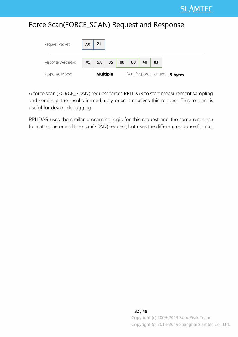
Force Scan(FORCE_SCAN) Request and Response
A force scan (FORCE_SCAN) request forces RPLIDAR to start measurement sampling
and send out the results immediately once it receives this request. This request is
useful for device debugging.
RPLIDAR uses the similar processing logic for this request and the same response
format as the one of the scan(SCAN) request, but uses the different response format.
A5 21 Request Packet:
A5 5A Response Descriptor:
05 00 00 40 81
Response Mode:
Multiple
Data Response Length:
5 bytes

33 / 49
Copyright (c) 2009-2013 RoboPeak Team
Copyright (c) 2013-2019 Shanghai Slamtec Co., Ltd.
Get Device Info (GET_INFO) Request and Response
RPLIDAR will send out its device information (e.g. serial number, firmware/hardware
version) to the host system once it receives this request.
Format of the Device Info Response Packets:
Figure 4-25 Format of a Device Info Data Response Packet
A5 50 Request Packet:
A5 5A Response Descriptor:
14 00 00 00 04
Response Mode: Single
Data Response
Length:
20 bytes
model
8 0
firmware_minor
8 0
firmware_major
8 0
hardware
8 0
serialnumber[0]
8 0
+0
+1
+2
+3
+4
Byte Offset
serialnumber[15]
8 0
+19
…
34 / 49
Copyright (c) 2009-2013 RoboPeak Team
Copyright (c) 2013-2019 Shanghai Slamtec Co., Ltd.
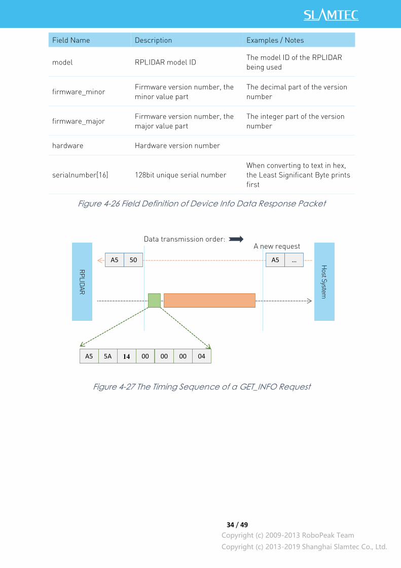
Field Name Description Examples / Notes
model RPLIDAR model ID The model ID of the RPLIDAR
being used
firmware_minor Firmware version number, the
minor value part
The decimal part of the version
number
firmware_major Firmware version number, the
major value part
The integer part of the version
number
hardware Hardware version number
serialnumber[16] 128bit unique serial number
When converting to text in hex,
the Least Significant Byte prints
first
Figure 4-26 Field Definition of Device Info Data Response Packet
Figure 4-27 The Timing Sequence of a GET_INFO Request
RP
LID
AR
Host S
ystem
A5 50 A5 …
A new request Data transmission order:
A5 5A 14 00 00 00 04
35 / 49
Copyright (c) 2009-2013 RoboPeak Team
Copyright (c) 2013-2019 Shanghai Slamtec Co., Ltd.
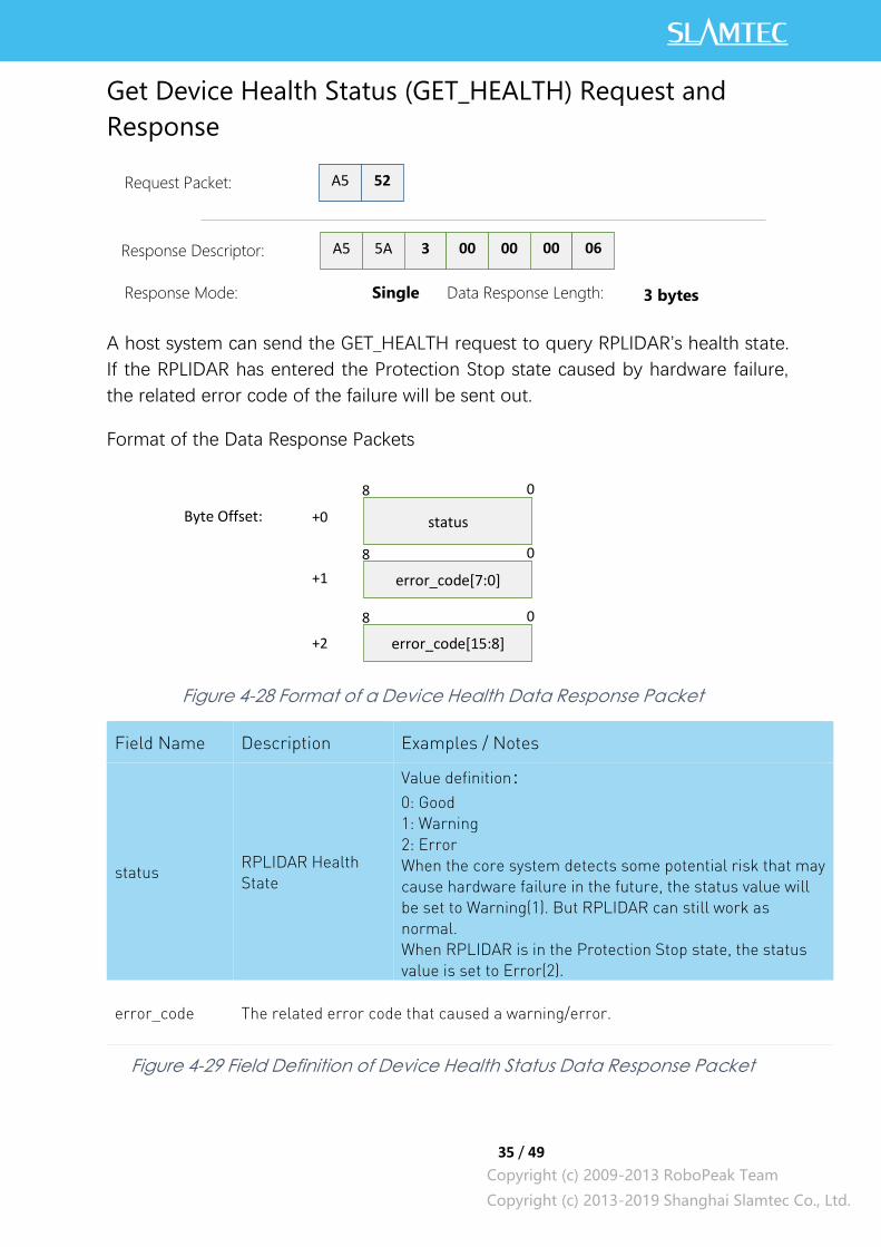
Get Device Health Status (GET_HEALTH) Request and
Response
A host system can send the GET_HEALTH request to query RPLIDAR’s health state.
If the RPLIDAR has entered the Protection Stop state caused by hardware failure,
the related error code of the failure will be sent out.
Format of the Data Response Packets
Figure 4-28 Format of a Device Health Data Response Packet
status RPLIDAR Health
State
Value definition:
0: Good
1: Warning
2: Error
When the core system detects some potential risk that may
cause hardware failure in the future, the status value will
be set to Warning(1). But RPLIDAR can still work as
normal.
When RPLIDAR is in the Protection Stop state, the status
value is set to Error(2).
error_code The related error code that caused a warning/error.
Figure 4-29 Field Definition of Device Health Status Data Response Packet
Field Name Description Examples / Notes
A5 52 Request Packet:
A5 5A Response Descriptor:
3 00 00 00 06
Response Mode:
Single
Data Response Length:
3 bytes
status
8 0
error_code[7:0]
8 0
error_code[15:8]
8 0
+0
+1
+2
Byte Offset:
36 / 49
Copyright (c) 2009-2013 RoboPeak Team
Copyright (c) 2013-2019 Shanghai Slamtec Co., Ltd.
When a host system detects RPLIDAR has entered the Protection Stop state, it can
set a RESET request to let RPLIDAR core system reboot to escape the Protection
Stop state. However, if RPLIDAR enters the Protection Stop state for several times,
this may be a sign of some unrecoverable damage has occurred in RPLIDAR.
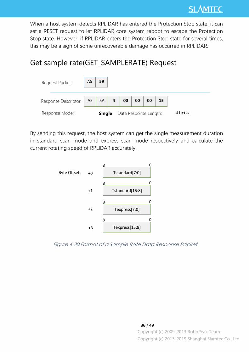
Get sample rate(GET_SAMPLERATE) Request
By sending this request, the host system can get the single measurement duration
in standard scan mode and express scan mode respectively and calculate the
current rotating speed of RPLIDAR accurately.
Figure 4-30 Format of a Sample Rate Data Response Packet
A5 59
A5 5A 4 00 00 00 15
4 bytes
Request Packet
Response Descriptor:
Response Mode:
Single
Data Response Length:
Tstandard[7:0]
8 0
Tstandard[15:8]
8 0
+0
+1
+2 Texpress[7:0]
8 0
Texpress[15:8]
8 0
+3
Byte Offset:
37 / 49
Copyright (c) 2009-2013 RoboPeak Team
Copyright (c) 2013-2019 Shanghai Slamtec Co., Ltd.
The following table describes the filed definition of the above packet.
Tstandard
In scan(SCAN) mode, the time used
when RPLIDAR takes a single laser
ranging
Unit: microsecond(uS)
It can be used for debugging the
rotating speed when the RPLIDAR
uses the SCAN request.
Texpress
In express scan(EXPRESS_SCAN)
mode, the time used when RPLIDAR
takes a single laser ranging
Unit: microsecond(uS)
It can be used for debugging the
rotating speed when the RPLIDAR
uses the EXPRESS_SCAN request.
Figure 4-31 Field Definition of Sample Rate Data Response Packet
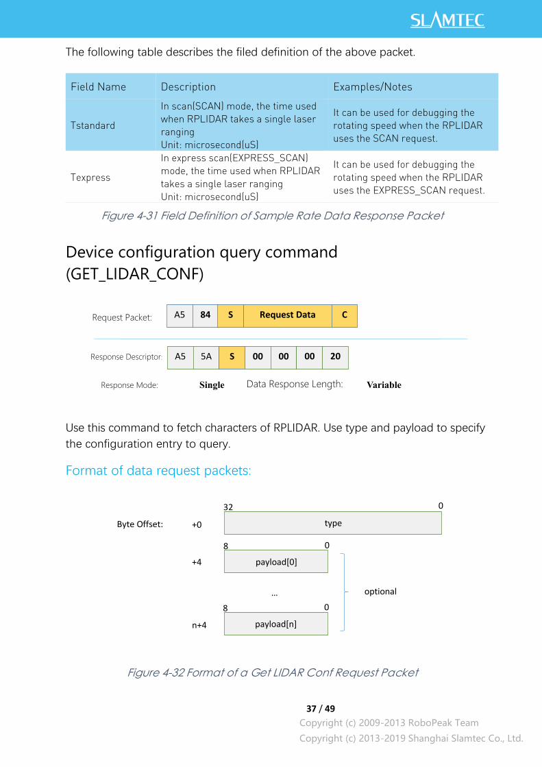
Device configuration query command
(GET_LIDAR_CONF)
Use this command to fetch characters of RPLIDAR. Use type and payload to specify
the configuration entry to query.
Format of data request packets:
Figure 4-32 Format of a Get LIDAR Conf Request Packet
Field Name Description Examples/Notes
A5 84 Request Packet:
A5 5A Response Descriptor:
S 00 00 00 20
Response Mode: Single Data Response Length:
Variable
S Request Data C
type
32 0
payload[0]
8 0
+0
+4
Byte Offset:
payload[n]
8 0
n+4
… optional
38 / 49
Copyright (c) 2009-2013 RoboPeak Team
Copyright (c) 2013-2019 Shanghai Slamtec Co., Ltd.
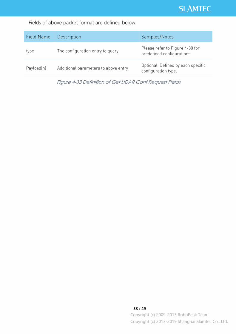
Fields of above packet format are defined below:
Field Name Description Samples/Notes
type The configuration entry to query Please refer to Figure 4-30 for
predefined configurations
Payload[n] Additional parameters to above entry Optional. Defined by each specific
configuration type.
Figure 4-33 Definition of Get LIDAR Conf Request Fields
39 / 49
Copyright (c) 2009-2013 RoboPeak Team
Copyright (c) 2013-2019 Shanghai Slamtec Co., Ltd.
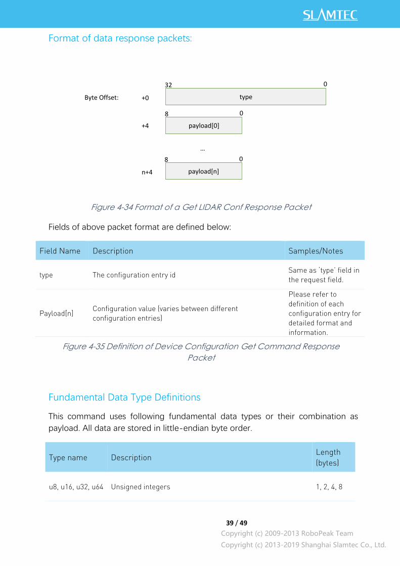
Format of data response packets:
Figure 4-34 Format of a Get LIDAR Conf Response Packet
Fields of above packet format are defined below:
Field Name Description Samples/Notes
type The configuration entry id Same as ‘type’ field in
the request field.
Payload[n] Configuration value (varies between different
configuration entries)
Please refer to
definition of each
configuration entry for
detailed format and
information.
Figure 4-35 Definition of Device Configuration Get Command Response
Packet
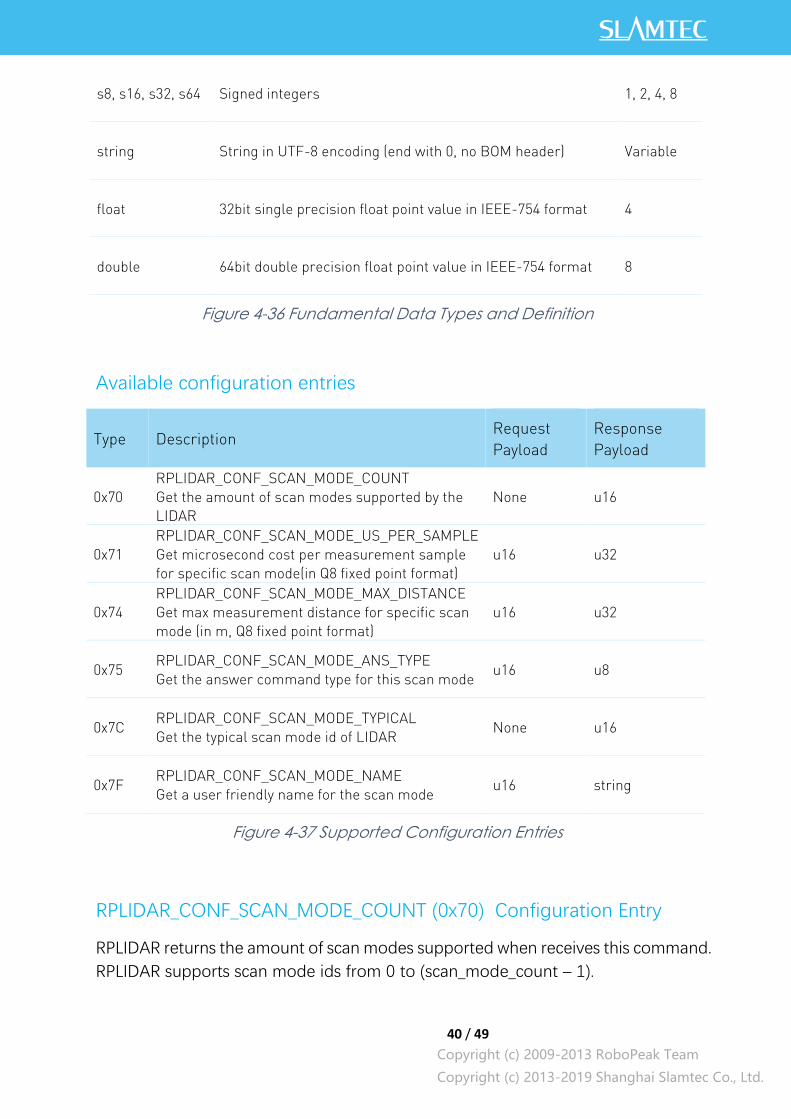
Fundamental Data Type Definitions
This command uses following fundamental data types or their combination as
payload. All data are stored in little-endian byte order.
Type name Description Length
(bytes)
u8, u16, u32, u64 Unsigned integers 1, 2, 4, 8
type
32 0
payload[0]
8 0
+0
+4
Byte Offset:
payload[n]
8 0
n+4
…
40 / 49
Copyright (c) 2009-2013 RoboPeak Team
Copyright (c) 2013-2019 Shanghai Slamtec Co., Ltd.
s8, s16, s32, s64 Signed integers 1, 2, 4, 8
string String in UTF-8 encoding (end with 0, no BOM header) Variable
float 32bit single precision float point value in IEEE-754 format 4
double 64bit double precision float point value in IEEE-754 format 8
Figure 4-36 Fundamental Data Types and Definition
Available configuration entries
Type Description Request
Payload
Response
Payload
0x70
RPLIDAR_CONF_SCAN_MODE_COUNT
Get the amount of scan modes supported by the
LIDAR
None u16
0x71
RPLIDAR_CONF_SCAN_MODE_US_PER_SAMPLE
Get microsecond cost per measurement sample
for specific scan mode(in Q8 fixed point format)
u16 u32
0x74
RPLIDAR_CONF_SCAN_MODE_MAX_DISTANCE
Get max measurement distance for specific scan
mode (in m, Q8 fixed point format)
u16 u32
0x75 RPLIDAR_CONF_SCAN_MODE_ANS_TYPE
Get the answer command type for this scan mode u16 u8
0x7C RPLIDAR_CONF_SCAN_MODE_TYPICAL
Get the typical scan mode id of LIDAR None u16
0x7F RPLIDAR_CONF_SCAN_MODE_NAME
Get a user friendly name for the scan mode u16 string
Figure 4-37 Supported Configuration Entries
RPLIDAR_CONF_SCAN_MODE_COUNT (0x70) Configuration Entry
RPLIDAR returns the amount of scan modes supported when receives this command.
RPLIDAR supports scan mode ids from 0 to (scan_mode_count – 1).
41 / 49
Copyright (c) 2009-2013 RoboPeak Team
Copyright (c) 2013-2019 Shanghai Slamtec Co., Ltd.
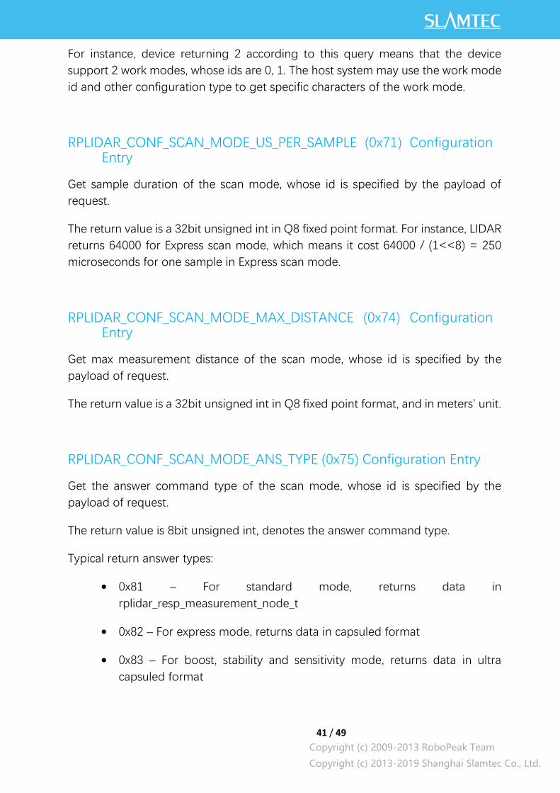
For instance, device returning 2 according to this query means that the device
support 2 work modes, whose ids are 0, 1. The host system may use the work mode
id and other configuration type to get specific characters of the work mode.
RPLIDAR_CONF_SCAN_MODE_US_PER_SAMPLE (0x71) Configuration Entry
Get sample duration of the scan mode, whose id is specified by the payload of
request.
The return value is a 32bit unsigned int in Q8 fixed point format. For instance, LIDAR
returns 64000 for Express scan mode, which means it cost 64000 / (1<<8) = 250
microseconds for one sample in Express scan mode.
RPLIDAR_CONF_SCAN_MODE_MAX_DISTANCE (0x74) Configuration Entry
Get max measurement distance of the scan mode, whose id is specified by the
payload of request.
The return value is a 32bit unsigned int in Q8 fixed point format, and in meters’ unit.
RPLIDAR_CONF_SCAN_MODE_ANS_TYPE (0x75) Configuration Entry
Get the answer command type of the scan mode, whose id is specified by the
payload of request.
The return value is 8bit unsigned int, denotes the answer command type.
Typical return answer types:
0x81 – For standard mode, returns data in
rplidar_resp_measurement_node_t
0x82 – For express mode, returns data in capsuled format
0x83 – For boost, stability and sensitivity mode, returns data in ultra
capsuled format
42 / 49
Copyright (c) 2009-2013 RoboPeak Team
Copyright (c) 2013-2019 Shanghai Slamtec Co., Ltd.
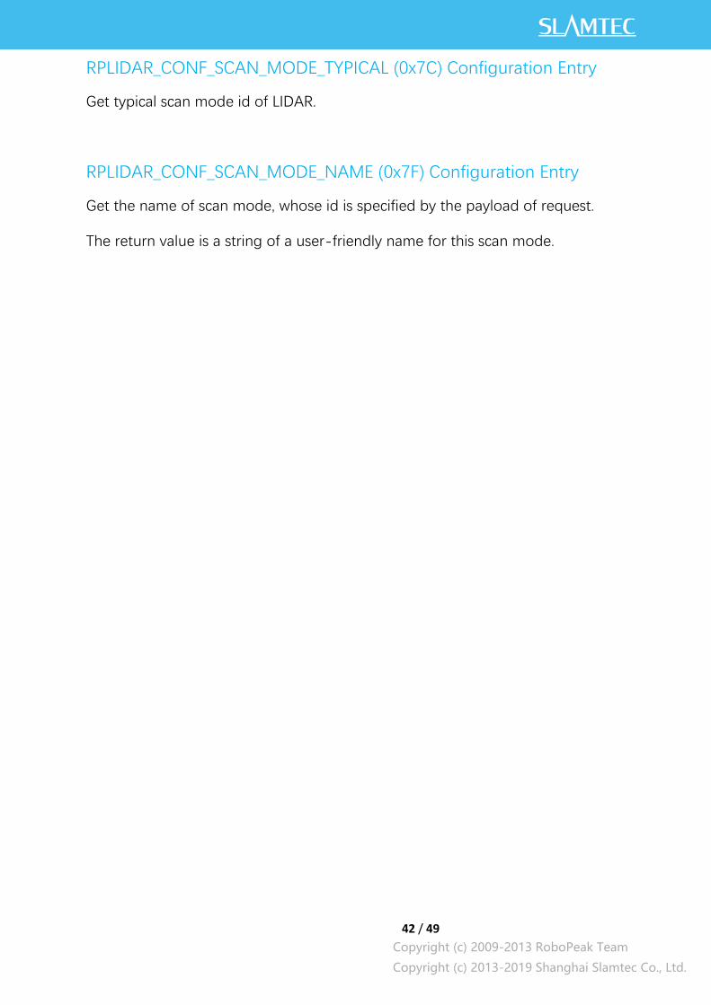
RPLIDAR_CONF_SCAN_MODE_TYPICAL (0x7C) Configuration Entry
Get typical scan mode id of LIDAR.
RPLIDAR_CONF_SCAN_MODE_NAME (0x7F) Configuration Entry
Get the name of scan mode, whose id is specified by the payload of request.
The return value is a string of a user-friendly name for this scan mode.

43 / 49
Copyright (c) 2009-2013 RoboPeak Team
Copyright (c) 2013-2019 Shanghai Slamtec Co., Ltd.
Device motor speed control command
(MOTOR_SPEED_CTRL)4
A host system can send this command to control the real-time motor speed of
RPLIDAR. And RPLIDAR will be enter the idle state only if have received the
command with Rpm = 0.
Format of the Data Request Packets:
Figure 4-38 Format of a MOTOR_SPEED_CTRL Request Packet
4Only RPLIDAR S1 serials support this command at present.
Request Packet:
A5 A8 02 Rpm C
Rpm
16 0
+0 Byte Offset:

44 / 49
Copyright (c) 2009-2013 RoboPeak Team
Copyright (c) 2013-2019 Shanghai Slamtec Co., Ltd.
Typical work flow of retrieving scanning data from an
RPLIDAR
It is recommended that a host system always follows the below sequence to enable
RPLIDA’s scanning operation and retrieve the scanning data. Before sending a SCAN
request, the host system should send a GET_HEALTH request in advance to query
the RPLIDAR’s health status. In case RPLIDAR is in the Protection Stop state, the host
system can send a RESET request to try to escape the Protection Stop state. Please
refer to the SDK code for implementation details.
Figure 5-1 Recommendation for Starting RPLIDAR Scanning and Data
Retrieving
Application Notes
Send a GET_HEALTH request
Receive timeout? Communication Error
Protection Stop? Send a RESET Request
Wait for 2ms
RPLIDAR hardware failure
Send a SCAN Request
RPLIDAR powered up
Receive timeout? Communication Error
Wait the Response Descriptor
Receive Measurement Sample
Receive timeout
Send a GET_HEALTH
request, check health
status
Process sample data
End of operation? Send a STOP request
Wait for 1ms
No
Yes
≥N
1st
No
Yes
Check motor status
Yes
No
No
No
Yes
45 / 49
Copyright (c) 2009-2013 RoboPeak Team
Copyright (c) 2013-2019 Shanghai Slamtec Co., Ltd.
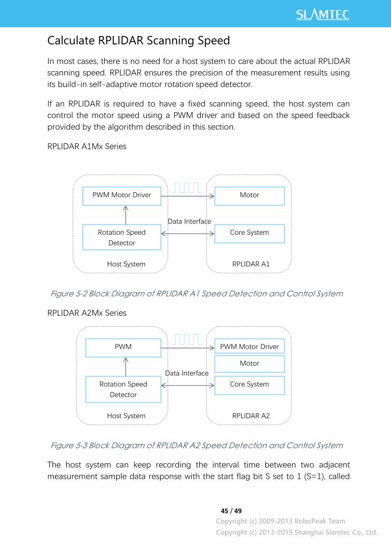
Calculate RPLIDAR Scanning Speed
In most cases, there is no need for a host system to care about the actual RPLIDAR
scanning speed. RPLIDAR ensures the precision of the measurement results using
its build-in self-adaptive motor rotation speed detector.
If an RPLIDAR is required to have a fixed scanning speed, the host system can
control the motor speed using a PWM driver and based on the speed feedback
provided by the algorithm described in this section.
RPLIDAR A1Mx Series
Figure 5-2 Block Diagram of RPLIDAR A1 Speed Detection and Control System
RPLIDAR A2Mx Series
Figure 5-3 Block Diagram of RPLIDAR A2 Speed Detection and Control System
The host system can keep recording the interval time between two adjacent
measurement sample data response with the start flag bit S set to 1 (S=1), called
Core System
Motor
Rotation Speed
Detector
PWM Motor Driver
Data Interface
Host System RPLIDAR A1
Core System
PWM Motor Driver
Rotation Speed
Detector
PWM
Data Interface
Host System RPLIDAR A2
Motor

46 / 49
Copyright (c) 2009-2013 RoboPeak Team
Copyright (c) 2013-2019 Shanghai Slamtec Co., Ltd.
∆T. The interval time represents how long the RPLIDAR has spent to perform a 360o
scan. So the actual scan speed can be calculated using the following equation:
RPM =1
∆𝑇∗ 60
The calculated value can be used as a feedback to control the motor speed.

47 / 49
Copyright (c) 2009-2013 RoboPeak Team
Copyright (c) 2013-2019 Shanghai Slamtec Co., Ltd.
Revision History
Date Description
2013-3-5 Initial version
2014-1-25 Modified related descriptions
2014-3-8 Added descriptions about the time requirement of sending request packet.
2015-8-21 Modified the incoherence in the context of GET_HEALTH
2016-4-10 Added descriptions for the RPLIDAR A2 newly added protocol
2016-5-4 Fixed a description bug
2016-10-28 Fixed a description bug in the EXPRESS_SCAN protocol section
2017-05-15 Release 1.0 Version
2018-03-08 Added notes for higher class scan modes in Express Mode protocol
2018-11-11 Added notes for GET_LIDAR_CONF and Ultra Capsuled Mode protocol
2019-03-28 Added note for Dense Capsuled Mode protocol
48 / 49
Copyright (c) 2009-2013 RoboPeak Team
Copyright (c) 2013-2019 Shanghai Slamtec Co., Ltd.
Image and Table Index
FIGURE 1-1 THE COMMUNICATION BETWEEN RPLIDAR AND HOST SYSTEM ..................................................... 3
FIGURE 2-1 RPLIDAR REQUEST/RESPONSE MODES ............................................................................................ 4
FIGURE 2-2 RPLIDAR SINGLE REQUEST - MULTIPLE RESPONSE MODE .............................................................. 5
FIGURE 2-3 RPLIDAR SINGLE REQUEST-NO RESPONSE MODE .......................................................................... 6
FIGURE 2-4 RPLIDAR REQUEST PACKETS’ FORMAT .......................................................................................... 6
FIGURE 2-5 RESPONSE PACKETS SENT DURING A SINGLE REQUEST-SINGLE RESPONSE MODE ........................... 8
FIGURE 2-6 RESPONSE PACKETS SENT DURING A SINGLE REQUEST-MULTIPLE RESPONSE MODE ....................... 8
FIGURE 2-7 RPLIDAR RESPONSE DESCRIPTORS’ FORMAT ................................................................................ 8
FIGURE 2-8 RPLIDAR DATA RESPONSE PACKETS VALUE ..................................................................................... 9
FIGURE 3-1 RPLIDAR’S MAJOR STATUS TRANSLATION .................................................................................. 10
FIGURE 3-2 RPLIDAR’S WORKING MODE DURING SCANNING ...................................................................... 11
FIGURE 3-3 TYPICAL SCAN MODES OF RPLIDAR ................................................................................................ 12
FIGURE 4-1 THE AVAILABLE REQUESTS OF RPLIDAR ......................................................................................... 13
FIGURE 4-2 THE TIMING SEQUENCE OF A STOP REQUEST ................................................................................. 14
FIGURE 4-3 THE TIMING SEQUENCE OF A RESET REQUEST ................................................................................ 14
FIGURE 4-4 FORMAT OF A RPLIDAR MEASUREMENT RESULT DATA RESPONSE PACKET .................................. 15
FIGURE 4-5 FIELD DEFINITION OF A RPLIDAR MEASUREMENT RESULT DATA RESPONSE PACKET ................... 16
FIGURE 4-6 ANGLE AND DISTANCE VALUE GEOMETRIC DEFINITION FOR RPLIDAR A1 SERIES ........................ 16
FIGURE 4-7 ANGLE AND DISTANCE VALUE GEOMETRIC DEFINITION FOR RPLIDAR A2 SERIES ........................ 17
FIGURE 4-8 THE COMMUNICATION STATUS AFTER HOST SYSTEM SENDING A SCAN REQUEST ....................... 17
FIGURE 4-9 FORMAT OF A RPLIDAR EXPRESS SCAN DATA REQUEST PACKET .................................................. 19
FIGURE 4-10 FIELD DEFINITION OF RPLIDAR EXPRESS SCAN DATA REQUEST PACKET .................................... 20
FIGURE 4-11 FORMAT OF A RPLIDAR EXPRESS SCAN DATA RESPONSE PACKET (LEGACY VERSION) .............. 21
FIGURE 4-12 FIELD DEFINITION OF RPLIDAR EXPRESS SCAN DATA RESPONSE PACKET .................................. 22
FIGURE 4-13 FIELD DEFINITION OF RPLIDAR EXPRESS SCAN CABIN DATA RESPONSE PACKET ....................... 23
FIGURE 4-14 THE COMMUNICATION STATUS SENDING OUT THE EXPRESS SCAN REQUEST .............................. 23
FIGURE 4-15 FORMAT OF A RPLIDAR EXPRESS SCAN DATA RESPONSE PACKET (EXTENDED VERSION) .......... 24
FIGURE 4-16 FIELD DEFINITION OF RPLIDAR EXPRESS SCAN DATA RESPONSE ULTRA CAPSULED PACKET ..... 25
FIGURE 4-17 FIELD DEFINITION OF RPLIDAR EXPRESS SCAN ULTRA CABIN DATA RESPONSE PACKET ........... 25
FIGURE 4-18 THE COMMUNICATION STATUS SENDING OUT THE ULTRA CAPSULED EXPRESS SCAN REQUEST 26
FIGURE 4-19 FORMAT OF A RPLIDAR EXPRESS SCAN DATA RESPONSE PACKET (DENSE VERSION) ............... 27
FIGURE 4-20 FIELD DEFINITION OF RPLIDAR EXPRESS SCAN DATA RESPONSE DENSE CAPSULED PACKET ..... 28
FIGURE 4-21 FIELD DEFINITION OF RPLIDAR EXPRESS SCAN DENSE CABIN DATA RESPONSE PACKET .......... 28
FIGURE 4-22 THE COMMUNICATION STATUS SENDING OUT THE DENSE CAPSULED EXPRESS SCAN REQUEST
..................................................................................................................................................................... 29
FIGURE 4-23 THE ABSTRACT DESCRIPTION FOR THE RESPONSE DATA PACKET OF EXPRESS SCAN REQUEST .... 30
FIGURE 4-24 THE ABSTRACT DESCRIPTION FOR THE RESPONSE DATA PACKET OF EXPRESS SCAN REQUEST .... 31
Appendix
49 / 49
Copyright (c) 2009-2013 RoboPeak Team
Copyright (c) 2013-2019 Shanghai Slamtec Co., Ltd.
FIGURE 4-25 FORMAT OF A DEVICE INFO DATA RESPONSE PACKET................................................................... 33
FIGURE 4-26 FIELD DEFINITION OF DEVICE INFO DATA RESPONSE PACKET ....................................................... 34
FIGURE 4-27 THE TIMING SEQUENCE OF A GET_INFO REQUEST ...................................................................... 34
FIGURE 4-28 FORMAT OF A DEVICE HEALTH DATA RESPONSE PACKET .............................................................. 35
FIGURE 4-29 FIELD DEFINITION OF DEVICE HEALTH STATUS DATA RESPONSE PACKET ..................................... 35
FIGURE 4-30 FORMAT OF A SAMPLE RATE DATA RESPONSE PACKET ................................................................. 36
FIGURE 4-31 FIELD DEFINITION OF SAMPLE RATE DATA RESPONSE PACKET ..................................................... 37
FIGURE 4-32 FORMAT OF A GET LIDAR CONF REQUEST PACKET ...................................................................... 37
FIGURE 4-33 DEFINITION OF GET LIDAR CONF REQUEST FIELDS ...................................................................... 38
FIGURE 4-34 FORMAT OF A GET LIDAR CONF RESPONSE PACKET .................................................................... 39
FIGURE 4-35 DEFINITION OF DEVICE CONFIGURATION GET COMMAND RESPONSE PACKET ............................. 39
FIGURE 4-36 FUNDAMENTAL DATA TYPES AND DEFINITION .............................................................................. 40
FIGURE 4-37 SUPPORTED CONFIGURATION ENTRIES .......................................................................................... 40
FIGURE 5-1 RECOMMENDATION FOR STARTING RPLIDAR SCANNING AND DATA RETRIEVING ....................... 44
FIGURE 5-2 BLOCK DIAGRAM OF RPLIDAR A1 SPEED DETECTION AND CONTROL SYSTEM ............................ 45
FIGURE 5-3 BLOCK DIAGRAM OF RPLIDAR A2 SPEED DETECTION AND CONTROL SYSTEM ............................ 45