Embed Size (px)
Citation preview

Operating Manual
az Packer
C-Pack 900
MG5088 BAG0137.2 04.21 Printed in Germany
Read and observe this operating manual before using
the implement for the first time! Keep it in a safe place
for future use.
en

2 C-Pack BAG0137.2 04.21
Reading the instruc-tion
manual and to adhere to it should not appear to be inconvenient and superfluous as it is not enough to hear from others and to realise that a machine is good, to buy it and to believe that now everything would work by itself. The person con-cerned would not only harm himself but also make the mistake of blaming the machine for the reason of a possible failure instead of himself. In order to ensure a good success one should go into the mind of a thing or make himself familiar with every part of the machine and to get acquainted with its handling. Only this way, you would be satisfied both with the machine as also with yourself. To achieve this is the purpose of this in-struction manual.
Leipzig-Plagwitz 1872.
Identification data
C-Pack BAG0137.2 04.21 3
Identification data
Manufacturer: AMAZONEN-WERKE
H. DREYER SE & Co. KG
Implement ID No.
Type: C-Pack
Permissible system pressure in bar:
Year of manufacture:
Factory:
Basic weight (kg):
Permissible total weight (kg):
Maximum load (kg):
Manufacturer's address
AMAZONEN-WERKE
H. DREYER SE & Co. KG
Postfach 51
D-49202
Tel.:
Fax:
E-mail:
Hasbergen, Germany
+ 49 (0) 5405 50 1-0
+ 49 (0) 5405 501-234
Spare part orders
Spare parts lists are freely accessible in the spare parts portal at www.amazone.de.
Please send orders to your AMAZONE dealer.
Formalities of the operating manual
Document number: MG5088
Compilation date: 04.21
Copyright AMAZONEN-WERKE H. DREYER SE & Co. KG, 2021
All rights reserved.
Reprinting, even of sections, permitted only with the approval of AMAZONEN-WERKE H. DREYER GmbH & Co. KG.

Foreword
4 C-Pack BAG0137.2 04.21
Foreword
Dear Customer,
You have chosen one of the quality products from the wide product range of AMAZONEN-WERKE, H. DREYER SE & Co. KG. We thank you for your confidence in our products.
On receiving the implement, check to see if it has been damaged during transport or if parts are missing. Using the delivery note, check that the implement has been delivered in full, including any special equipment ordered. Damage can only be rectified if problems are signalled immediately.
Before commissioning, read and understand this operating manual, and particularly the safety information. Only after careful reading will you be able to benefit from the full scope of your newly purchased implement.
Please ensure that all the implement operators have read this operat-ing manual before the implement is commissioned.
Should you have any questions or problems, please consult this op-erating manual or contact your local service partner.
Regular maintenance and timely replacement of worn or damaged parts increases the lifespan of your implement.
User evaluation
Dear Reader,
We update our operating manuals regularly. Your suggestions for improvement help us to create ever more user-friendly manuals. Send us your suggestions by fax.
AMAZONEN-WERKE
H. DREYER SE & Co. KG
Postfach 51
D-49202
Tel.:
Fax:
E-mail:
Hasbergen, Germany
+ 49 (0) 5405 50 1-0
+ 49 (0) 5405 501-234

Table of contents
C-Pack BAG0137.2 04.21 5
1 User Information .......................................................................................... 7 1.1 Purpose of the document ......................................................................................................... 7 1.2 Locations in the operating manual ........................................................................................... 7 1.3 Diagrams .................................................................................................................................. 7
2 General Safety Instructions ........................................................................ 8 2.1 Obligations and liability ............................................................................................................ 8 2.2 Representation of safety symbols .......................................................................................... 10 2.3 Organisational measures ....................................................................................................... 11 2.4 Safety and protection equipment ........................................................................................... 11 2.5 Informal safety measures ....................................................................................................... 11 2.6 User training ........................................................................................................................... 12 2.7 Safety measures in normal operation .................................................................................... 13 2.8 Danger from residual energy ................................................................................................. 13 2.9 Maintenance and repair work, fault elimination ..................................................................... 13 2.10 Design changes ..................................................................................................................... 13 2.10.1 Spare and wear parts and aids .............................................................................................. 14 2.11 Cleaning and disposal ............................................................................................................ 14 2.12 User workstation .................................................................................................................... 14 2.13 Warning symbols and other signs on the implement ............................................................. 15 2.14 Potential risks from not observing the safety instructions ...................................................... 18 2.15 Safety-conscious working ...................................................................................................... 18 2.16 Safety information for users ................................................................................................... 19 2.16.1 General safety and accident prevention information ............................................................. 19 2.16.2 Cleaning, maintenance and repair ......................................................................................... 22
3 Loading and unloading ............................................................................. 23
4 Product description ................................................................................... 24 4.1 Overview of the assemblies ................................................................................................... 24 4.2 Transportation equipment ...................................................................................................... 25 4.3 Intended use .......................................................................................................................... 26 4.4 Danger areas and danger points ........................................................................................... 27 4.5 Rating plate and CE mark ...................................................................................................... 27 4.6 Technical Data ....................................................................................................................... 28 4.7 Necessary tractor equipment ................................................................................................. 29 4.8 Noise production data ............................................................................................................ 29
5 Layout and function ................................................................................... 30 5.1 Packer rings and cleaning lines ............................................................................................. 30 5.2 Three-point hitch frame .......................................................................................................... 31 5.3 Cam ring roller ....................................................................................................................... 31
6 Start-up ....................................................................................................... 32 6.1 Checking the suitability of the tractor ..................................................................................... 33 6.1.1 Calculating the actual values for the total tractor weight, tractor axle loads and load
capacities, as well as the minimum ballast ............................................................................ 33 6.2 Securing the tractor / implement against unintentional start-up and rolling ........................... 37
7 Coupling and uncoupling the implement ................................................ 38 7.1 Coupling the implement ......................................................................................................... 39 7.2 Uncoupling the implement ..................................................................................................... 40
8 Use of the implement ................................................................................. 41 8.1 Transportation ........................................................................................................................ 41

Table of contents
6 C-Pack BAG0137.2 04.21
8.2 Transport position / working position ..................................................................................... 42 8.3 Use ........................................................................................................................................ 45
9 Cleaning, maintenance and repair ........................................................... 46 9.1 Cleaning ................................................................................................................................ 47 9.2 Lubrication specifications ...................................................................................................... 47 9.3 Screw tightening torques ....................................................................................................... 49

User Information
C-Pack BAG0137.2 04.21 7
1 User Information
The User Information section provides information on use of the oper-ating manual.
1.1 Purpose of the document
This operating manual
• describes the operation and maintenance of the implement.
• provides important information on safe and efficient handling of the implement.
• is a component part of the implement and should always be kept with the implement or the towing vehicle.
• Keep it in a safe place for future use.
1.2 Locations in the operating manual
All the directions specified in the operating manual are always seen in the direction of travel.
1.3 Diagrams
Instructions and responses
Activities to be carried out by the user are given as numbered instruc-tions. Always keep to the order of the instructions. The reaction to instructions is given by an arrow. Example:
1. Instruction 1
→ Implement response to instruction 1
2. Instruction 2
Lists
Lists without an essential order are shown as a list with bullets. Ex-ample:
• Point 1
• Point 2
Item numbers in diagrams
Numbers in round brackets refer to items in diagrams.
Example (6) → Item 6

General Safety Instructions
8 C-Pack BAG0137.2 04.21
2 General Safety Instructions
This section contains important information on safe operation of the implement.
2.1 Obligations and liability
Comply with the instructions in the operating manual
Knowledge of the basic safety information and safety regulations is a basic requirement for safe handling and fault-free implement opera-tion.
Obligations of the operator
The operator is obliged only to let those people work with/on the im-plement who
• are aware of the basic workplace safety information and accident prevention regulations.
• Have been introduced to working with/on the implement.
• have read and understood this operating manual.
The operator is obliged
• to keep all the warning symbols on the implement in a legible state.
• to replace damaged warning symbols.
Obligations of the user
Before starting work, anyone charged with working with/on the imple-ment is obliged
• to comply with the basic workplace safety instructions and acci-dent prevention regulations.
• To read and observe the section "General safety information" of this operating manual.
• To read the section "Warning symbols and other labels on the implement" (page 15) of this operating manual and to follow the safety instructions represented by the warning symbols when operating the implement.
• To get to know the implement. • To read the sections of this operating manual, important for car-
rying out your work.
If the user discovers that a function is not working properly, then they must eliminate this fault immediately. If this is not the task of the user or if the user does not possess the appropriate technical knowledge, then they should report this fault to their superior (operator).

General Safety Instructions
C-Pack BAG0137.2 04.21 9
Risks in handling the implement
The implement has been constructed to the state-of-the art and the recognised rules of safety. However, operating the implement may cause risks and restrictions to
• the health and safety of the user or third parties,
• the implement,
• other property.
Only use the implement
• for the purpose for which it was intended.
• in a perfect state of repair.
Eliminate any faults immediately which could impair safety.
Guarantee and liability
Our "General conditions of sales and delivery" are always applicable. These shall be available to the operator, at the latest on conclusion of the contract. Guarantee and liability claims for damage to people or property will be excluded if they can be traced back to one or more of the following causes:
• Improper use of the implement.
• Improper installation, commissioning, operation and mainte-nance of the implement.
• Operation of the implement with defective safety equipment or improperly attached or non-functioning safety equipment.
• Non-compliance with the instructions in the operating manual regarding commissioning, operation and maintenance.
• Unauthorised design changes to the implement.
• Insufficient monitoring of implement parts which are subject to wear.
• Improperly executed repairs.
• Disasters through the impact of foreign bodies and Acts of God.

General Safety Instructions
10 C-Pack BAG0137.2 04.21
2.2 Representation of safety symbols
Safety instructions are indicated by the triangular safety symbol and the highlighted signal word. The signal word (danger, warning, cau-tion) describes the severity of the risk, and carries the following mean-ing:
DANGER identifies a direct threat at high risk which can result in death or most serious bodily harm (loss of limbs or long-term harm), should it not be prevented. If the instructions are not followed, then this will result in imme-diate death or serious physical injury.
WARNING
Indicates a medium risk, which could result in death or (serious) physical injury if not avoided. If the instructions are not followed, then this may result in death or serious physical injury.
CAUTION Indicates a low risk which could cause minor or medium level physical injury or damage to property if not avoided.
IMPORTANT Indicates an obligation to special behaviour or an activity re-quired for proper implement handling. Non-compliance with these instructions can cause faults on the implement or disturbance to the environment.
NOTE Indicates handling tips and particularly useful information. These instructions will help you to use all the functions of your implement in the best way possible.

General Safety Instructions
C-Pack BAG0137.2 04.21 11
2.3 Organisational measures
The operator must provide the necessary personal protective equip-ment as per the information provided by the manufacturer of the crop protection agent to be used, such as:
• Protective goggles,
• Safety shoes,
• Protective overall,
• Skin protection agents etc.
The operation manual
• Must always be kept at the place at which the implement is op-erated.
• Must always be easily accessible for the user and maintenance personnel.
Check all the available safety equipment regularly.
2.4 Safety and protection equipment
Before starting up the implement each time, all the safety and protec-tion equipment must be properly attached and fully functional. Check all safety and protection equipment regularly.
Faulty safety equipment
Faulty or disassembled safety and protection equipment can lead to dangerous situations.
2.5 Informal safety measures
As well as all the safety information in this operating manual, comply with the general, national regulations pertaining to accident prevention and environmental protection.
When driving on public roads and routes you should comply with the statutory road traffic regulations.

General Safety Instructions
12 C-Pack BAG0137.2 04.21
2.6 User training
Only trained and instructed persons should be allowed to work with/on the implement. The responsibilities of the operating and maintenance personnel must be clearly defined.
People being trained may only work with/on the implement under the supervision of an experienced person.
Person
Activity
Person special-ly trained for the
activity 1)
Trained person 2)
Persons with specialist training
(specialist workshop) 3)
Loading/Transport X X X
Start-up -- X --
Set-up, tool installation -- -- X
Operation -- X --
Maintenance -- -- X
Troubleshooting and fault elimina-tion
X -- X
Disposal X -- --
Legend: X..permitted --..not permitted
1) A person who can assume a specific task and who can carry out this task for an appropriately qualified company.
2) Instructed persons are those who have been instructed in their assigned tasks and in the possible risks in the case of improper behaviour, have been trained if necessary, and have been in-formed about the necessary protective equipment and measures.
3) People with specialist technical training shall be considered as a specialist. Due to their specialist training and their knowledge of the appropriate regulations, they can evaluate the work with which they have been charged and detect possible dangers.
Comment: A qualification equivalent to specialist training can be obtained
from several years' experience in the relevant field.
If maintenance and repair work on the implement is additionally marked "Workshop work", only a specialist workshop may carry out such work. The personnel of a specialist workshop shall possess the appropriate knowledge and suitable aids (tools, lifting and support equipment) for carrying out the maintenance and repair work on the implement in a way which is both appropriate and safe.

General Safety Instructions
C-Pack BAG0137.2 04.21 13
2.7 Safety measures in normal operation
Only operate the implement if all the safety and protection equipment is fully functional.
Check the implement at least once a day for visible damage and check the function of the safety and protection equipment.
2.8 Danger from residual energy
Note that there may be residual mechanical, hydraulic, pneumatic and electrical/electronic energy on the implement.
Use appropriate measures to inform the operating personnel. You can find detailed information in the relevant sections of this operating manual.
2.9 Maintenance and repair work, fault elimination
Carry out prescribed setting, maintenance and inspection work in good time.
Secure all media such as compressed air and the hydraulic system against unintentional start-up.
Carefully fix and secure larger assemblies to lifting gear when carry-ing out replacement work.
Check loosened threaded connections for tightness. When the maintenance work is completed, check the functioning of the safety devices.
2.10 Design changes
You may make no changes, expansions or modifications to the im-plement without the authorisation of AMAZONEN-WERKE. This also applies when welding support parts.
Any expansion or modification work shall require the written approval of AMAZONEN-WERKE. Only use modification and accessory parts approved by AMAZONEN-WERKE so that the type approval, for ex-ample, remains valid in accordance with national and international regulations.
Vehicles with an official type approval or with equipment connected to a vehicle with a valid type approval or approval for road transport according to the German road traffic regulations must be in the state specified by the approval.
WARNING Risk of crushing, cutting, being trapped or drawn in, or impact through the failure of support parts. It is strictly forbidden to • drill holes in the frame or on the running gear. • increase the size of existing holes on the frame or the running
gear. • weld support parts.
General Safety Instructions
14 C-Pack BAG0137.2 04.21
2.10.1 Spare and wear parts and aids
Immediately replace any implement parts which are not in a perfect state.
Only use genuine AMAZONE spare and wear parts, or those ap-proved by AMAZONEN-WERKE, so that the operating permit remains valid according to the national and international regulations. The use of spare and wear parts from third parties does not guarantee that they have been constructed such that they meet the requirements placed on them.
AMAZONEN-WERKE shall accept no liability for damage caused by the use of non-approved spare and wear parts or aids.
2.11 Cleaning and disposal
Handle and dispose of any materials used carefully, in particular
• when carrying out work on lubrication systems and equipment and
• when cleaning using solvents.
2.12 User workstation
The implement may be operated by only one person sitting in the driver's seat of the tractor.

General Safety Instructions
C-Pack BAG0137.2 04.21 15
2.13 Warning symbols and other signs on the implement
Always keep all the warning pictograms of the implement clean and in a legible state. Replace illegible warning pictograms. You can obtain the warning pictograms from your dealer using the order number (e.g. MD 075).
Warning symbols - structure
Warning pictograms indicate danger areas on the implement and warn of residual dangers. Permanent or unexpected dangers exist in these areas.
A warning symbol consists of two fields:
Field 1
is a symbol describing the danger, surrounded by triangular safety symbol.
Field 2 is a symbol showing how to avoid the danger.
Warning symbols - explanation
The column Order number and explanation provides an explanation of the neighbouring warning symbol. The description of the warning symbols is always the same and specifies, in the following order:
1. A description of the danger.
For example: risk of cutting
2. The consequence of non-compliance with the risk avoidance instructions.
For example: causes serious injuries to fingers or hands.
3. Risk avoidance instructions.
For example: only touch implement parts when they have come to a complete standstill.

General Safety Instructions
16 C-Pack BAG0137.2 04.21
Order No. and explanation Warning symbols
MD 078 Risk of crushing of fingers/hand by accessi-ble, moving parts of the implement! This hazard can cause extremely serious injuries resulting in the loss of limbs.
Never reach into the danger area when the trac-tor engine is running with the PTO shaft or hy-draulic/electrical system connected.
MD 095 Read and follow the operating manual and safety information before starting up the implement!
MD 097 Risk of crushing and contusions between the rear of the tractor and the implement when coupling and uncoupling the implement! These dangers can cause extremely serious and potentially fatal injuries.
• It is forbidden to actuate the three-point hydraulic system of the tractor as long as persons are standing between the rear of the tractor and the implement.
• Actuate the operator controls for the trac-tor's three-point hydraulic system: ο Only from the intended workstation
alongside the tractor. ο Only when you are outside the danger
area between the tractor and the im-plement.
MD 100 This symbol indicates attachment points for lifting gear for loading the implement.

General Safety Instructions
C-Pack BAG0137.2 04.21 17
MD 102 Dangerous situations for the operator due to unintentional starting / rolling of the imple-ment during all work on the implement, e.g. installation, adjustment, troubleshooting, cleaning or maintenance. The potential dangers can inflict severe and po-tentially fatal injuries on all parts of the body. • Secure the tractor and the implement
against unintentional start-up and rolling be-fore any intervention in the implement.
• Depending on the type of intervention, read and understand the information in the rele-vant sections of this operating manual.
MD 114 This symbol indicates a lubrication point
General Safety Instructions
18 C-Pack BAG0137.2 04.21
2.14 Potential risks from not observing the safety instructions
Non-compliance with the safety information
• can pose both a danger to people and also to the environment and implement.
• can lead to the loss of all warranty claims.
In particular, non-compliance with the safety information could pose the following risks:
• Danger to people through non-secured working areas.
• Failure of important implement functions.
• Failure of prescribed methods of maintenance and repair.
• Danger to people through mechanical and chemical influences.
• Risk to the environment through leakage of hydraulic fluid.
2.15 Safety-conscious working
In addition to the safety information in this operating manual, compli-ance with the generally applicable national workplace safety and ac-cident prevention regulations is mandatory.
Comply with the accident prevention instructions on the warning pic-tograms.
When driving on public roads and routes, comply with the appropriate statutory road traffic regulations.

General Safety Instructions
C-Pack BAG0137.2 04.21 19
2.16 Safety information for users
WARNING Before starting up the implement and the tractor, always check their traffic and operational safety.
2.16.1 General safety and accident prevention information
• Beside these instructions, comply with the generally applicable national safety and accident prevention regulations.
• The warning symbols and other labels attached to the implement provide important information on safe implement operation. Compliance with this information is in the interests of your safety.
• Before moving off and starting up the implement, check the im-mediate area of the implement (children). Ensure that you can see clearly.
• It is forbidden to ride on the implement or use it as a means of transport!
• Drive in such a way that you always have full control over the tractor with the attached implement.
In so doing, take your personal abilities into account, as well as the road, traffic, visibility and weather conditions, the driving characteristics of the tractor and the connected or coupled im-plement.
Coupling and uncoupling the implement
• You may only couple and transport the implement on a tractor that fulfils the power requirements.
• When connecting implements to the tractor's three-point hydrau-lic system, the attachment categories of the tractor and the im-plement must always be the same!
• When coupling implements to the front or the rear of the tractor, the following may not be exceeded:
ο The approved total tractor weight
ο The approved tractor axle loads
ο The approved load capacities of the tractor tyres
• Secure the tractor and the implement against unintentional movement before coupling or uncoupling the implement.
• It is forbidden for people to stand between the implement to be coupled and the tractor while the tractor is moving towards the implement!
Any helpers may only act as guides standing next to the vehi-cles, and may only move between the vehicles when both are at a standstill.
• Secure the operating lever of the tractor hydraulic system so that unintentional raising or lowering is impossible, before connecting the implement to or disconnecting the implement from the trac-tor's three-point hydraulic system.
General Safety Instructions
20 C-Pack BAG0137.2 04.21
• When coupling and uncoupling implements, move the support equipment (if available) to the appropriate position (stability).
• When actuating the support equipment, there is a danger of inju-ry from contusion and cutting points!
• Be particularly careful when coupling the implement to the tractor or uncoupling it from the tractor! There are contusion and cutting points in the area of the coupling point between the tractor and the implement.
• It is forbidden for people to stand between the tractor and the implement when actuating the three-point hydraulic system.
• Connect the implement to the prescribed equipment in accord-ance with the specifications.
• The release ropes for quick action couplings must hang loosely and may not release themselves when lowered.
• Also ensure that uncoupled implements are stable!
Use of the implement
• Before starting work, ensure that you understand all the equip-ment and actuation elements of the implement and their function. There is no time for this when the implement is already in opera-tion.
• Do not wear loose-fitting clothing. Loose clothing increases the risk of being caught by the drive shaft.
• Only start-up the implement, when all the safety equipment has been attached and is in the safety position.
• Comply with the maximum load of the connected implement and the approved axle and support loads of the tractor. If necessary, drive only with a partially filled tank.
• It is forbidden to stand in the working area of the implement. • It is forbidden to stand in the turning and swivel range of the
implement. • There are crushing and cutting points at externally-actuated (e.g.
hydraulic) implement points. • Only actuate externally-actuated implement parts when you are
sure that no-one is standing within the prescribed safety dis-tance.
• Secure the tractor against unintentional start-up and rolling, be-fore you leave the tractor.
For this: ο Lower the implement onto the ground ο apply the parking brake ο Switch off the tractor engine ο Remove the ignition key

General Safety Instructions
C-Pack BAG0137.2 04.21 21
Implement transportation
• When using public roads, national road traffic regulations must be observed.
• Before moving off, check: ο The correct connection of the supply lines ο The lighting system for damage, function and cleanliness ο The brake and hydraulic system for visible damage ο That the parking brake is completely released ο The functioning of the brake system
• Ensure that the tractor has sufficient steering and braking power. Any implements and front/rear weights connected to the tractor
influence the driving behaviour and the steering and braking power of the tractor.
• If necessary, use front weights. The front tractor axle must always be loaded with at least 20% of
the empty tractor weight, in order to ensure sufficient steering power.
• Always fix the front or rear weights to the intended fixing points according to regulations.
• Comply with the maximum load of the connected implement and the approved axle and support loads of the tractor.
• The tractor must guarantee the prescribed brake delay for the loaded vehicle combination (tractor plus connected implement).
• Check the brake power before moving off. • When turning corners with the implement connected, take the
broad load and balance weight of the implement into account. • Before moving off, ensure sufficient side locking of the tractor
lower links, when the implement is attached to the three-point hydraulic system or lower links of the tractor.
• Before moving off, move all the swivel implement parts to the transport position.
• Before moving off, secure all the swivel implement parts in the transport position against risky position changes. Use the transport locks intended for this.
• Before moving off, lock the operating lever of the tractor's three-point hydraulic system against the unintentional raising or lower-ing of the connected or hitched implement.
• Check that the transport equipment, e.g. lighting, warning equipment and protective equipment, is correctly mounted on the implement.
• Before transportation, carry out a visual check that the upper and lower link bolts are firmly fixed with the lynch pin against uninten-tional release.
• Adjust your driving speed to the prevailing conditions. • Before driving downhill, switch to a low gear.
• Before moving off, always switch off the independent wheel braking (lock the pedals).

General Safety Instructions
22 C-Pack BAG0137.2 04.21
2.16.2 Cleaning, maintenance and repair
• Repair-, maintenance- and cleaning operations as well as the remedy of function faults should principally be conducted with
ο The drive is switched off
ο The tractor engine is at a standstill
ο the ignition key has been removed
ο The implement plug has been disconnected from the on-board computer
• Regularly check the nuts and bolts for firm seating and retighten them as necessary.
• Secure the raised implement and/or raised implement parts against unintentional lowering before performing any cleaning, maintenance or repair work on the implement!
• When replacing work tools with blades, use suitable tools and gloves.
• Dispose of oils, greases and filters in the appropriate way.
• Disconnect the cable to the tractor generator and battery, before carrying out electrical welding work on the tractor and on at-tached implements.
• Spare parts must comply at least with the specified technical requirements of AMAZONEN-WERKE. This is ensured through the use of genuine AMAZONE spare parts.

Loading and unloading
C-Pack BAG0137.2 04.21 23
3 Loading and unloading
WARNING Risk of crushing due to accidental falling of a implement at-tached to a load carrier during loading and unloading!
• Use only slings (ropes, belts, chains, etc.) with a minimum ten-sile strength greater than the total weight of the implement (see Technical data).
• Only attach your lifting equipment to/at the designated points. • Never remain in or enter the area below a raised, unsecured
load.

Product description
24 C-Pack BAG0137.2 04.21
4 Product description
This section:
• provides a comprehensive overview of the implement structure.
• provides the names of the individual modules and controls.
If possible, read this section when actually at the implement. This helps you to understand the implement better.
4.1 Overview of the assemblies
(1) Three-point hitch
(2) Packer rings
(3) Cleaning line
(4) Hook linkage
(5) Stands
(6) Transport safeguard
Product description
C-Pack BAG0137.2 04.21 25
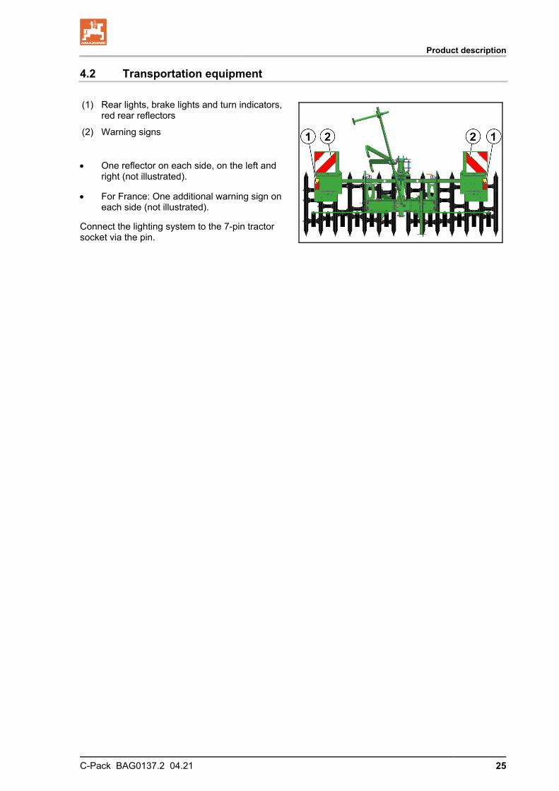
4.2 Transportation equipment
(1) Rear lights, brake lights and turn indicators, red rear reflectors
(2) Warning signs
• One reflector on each side, on the left and right (not illustrated).
• For France: One additional warning sign on each side (not illustrated).
Connect the lighting system to the 7-pin tractor socket via the pin.

Product description
26 C-Pack BAG0137.2 04.21
4.3 Intended use
The C-Pack roller
• Is built for conventional use as a trailing packer roller for AMA-ZONE ploughs in agricultural operations.
• Is coupled to the tractor for transportation using the tractor top link and lower link and is operated by one person.
• Is not suitable for front mounting.
Sloping terrain can be traversed as follows:
• Along the contours
Direction of travel to left 20 %
Direction of travel to right 20 %
• Along the gradient
Up the slope 20 %
Down the slope 20 %
"Intended use" also covers:
• Compliance with all the instructions in this operating manual.
• Execution of inspection and maintenance work.
• Exclusive use of genuine AMAZONE spare parts.
Other uses to those specified above are forbidden and shall be con-sidered as improper.
For any damage resulting from improper use
• the operator bears the sole responsibility,
• AMAZONEN-WERKE accepts no liability.

Product description
C-Pack BAG0137.2 04.21 27
4.4 Danger areas and danger points
The danger area is the area around the implement in which people can be caught:
• work movements made by the implement and its tools
• materials or foreign bodies thrown out of the implement
• by unintentional rolling of the tractor and the implement
Within the implement danger area, there are danger points with per-manent or unexpected risks. Warning pictograms indicate these dan-ger points and warn against residual dangers, which cannot be elimi-nated for construction reasons. Here, the special safety regulations of the appropriate section shall be valid.
No-one may stand in the implement danger area:
• as long as the tractor and implement are not protected against unintentional start-up and running.
The operating person may only move the implement or switch or drive the tools from the transport position to the working position or vice-versa when there is no-one in the implement danger area.
The following danger areas exist:
• Between the tractor and the implement, particularly during cou-pling and uncoupling procedures.
• Where there are moving components.
• When the implement is in motion.
• Underneath raised, unsecured implements or parts of imple-ments.
4.5 Rating plate and CE mark
Machine rating plate
The following information is specified on the ra-ting plate and the CE mark:
(1) Implement number
(2) Vehicle identification number
(3) Product
(4) Permissible technical implement weight
(5) Model year
(6) Year of manufacture

Product description
28 C-Pack BAG0137.2 04.21
4.6 Technical Data
C-Pack 2400-900
2600-900
2800-900
3000-900
Working width [mm] 2400 2600 2800 3000
Transport width [mm] 2270 2470 2670 2870
Spacing of the rings [mm] 200 200 200 200
Ring diameter [mm] 900 900 900 900
Number of rings 12 13 14 15
Ring profile 36° 36° 36° 36°
Attachment category Category II
Centre of gravity distance (d) [mm] 655
With cam ring roller 1010
Basic weight (empty weight)
C-Pack 2400-900
2600-900
2800-900
3000-900
Basic implement C-Pack 900S [kg] 375 375 375 375
Packer ring set [kg] 964 990 1130 1200
Cleaning line set [kg] 16 18 20 22
Cam ring roller [kg] 690 690 706 706
Lighting [kg] 25 25 25 25
The basic weight (net weight) is the total weight of the basic imple-ment and the respective implement attachments.

Product description
C-Pack BAG0137.2 04.21 29
4.7 Necessary tractor equipment
For operation of the implement in compliance with the intended use, the tractor must fulfil the following requirements.
Electrical system
Battery voltage: • 12 V (volts)
Lighting socket: • 7-pin
Three-point hitch
• The lower links of the tractor must have lower link hooks.
• The upper links of the tractor must have upper link hooks.
4.8 Noise production data
The workplace-related emission value (acoustic pressure level) is 74 dB(A), measured in operating condition at the ear of the tractor driver with the cabin closed.
Measuring unit: OPTAC SLM 5.
The noise level is primarily dependent on the vehicle used.

Layout and function
30 C-Pack BAG0137.2 04.21
5 Layout and function
The C-Pack packer breaks the soil clods after ploughing and provides
a level soil surface.
During operation, the packer is pulled on the hook linkage by the swivel arm of the plough, it is uncoupled at the headlands, and after the headlands it is coupled via the second hook linkage and is pulled behind the plough in the opposite direction.
The width of the packer should exceed the width of the plough by 10%.
5.1 Packer rings and cleaning lines
The number of mounted packer rings determines the working width.
Additional packer rings can be mounted.
The cleaning lines prevent soil from clinging to the packer rings.
(1) Packer ring
(2) Cleaning line

Layout and function
C-Pack BAG0137.2 04.21 31
5.2 Three-point hitch frame
The frame is designed such that it meets the dimensions of a Category II three-point hitch.
(1) Upper coupling point for Category II locking bolts.
(2) Lower coupling point for Category II locking bolts.
• Upper link pins and lower link pins with locking linch pins.
5.3 Cam ring roller
The cam ring roller is a trailing roller behind the C-Pack.
In transport position, it is transported with the C-Pack packer.
(1) Cam rings
(2) Hook tube for attachment in transport posi-tion
(3) Support for the lighting
(4) Folding linkage for coupling on the C-Pack
(5) Swivelling hook for locking the folding link-age in operating position
(6) Coupling point on the C-Pack

Start-up
32 C-Pack BAG0137.2 04.21
6 Start-up
This section contains information • on initial operation of your implement • on checking how you may mount / tow the implement to your
tractor.
• Before operating the implement for the first time the operator must have read and understood the operating manual.
• Follow the instructions given in the section "Safety instructions for the operator" from page 19 onwards when ο Coupling and uncoupling the implement ο Implement transportation ο Use of the implement
• Only couple and transport the implement to/with a tractor which is suitable for the task.
• Tractor and implement must satisfy the national road traffic regu-lations!
• Vehicle owner and vehicle operator are responsible for compli-ance with the statutory provisions of the national road traffic reg-ulations!

Start-up
C-Pack BAG0137.2 04.21 33
6.1 Checking the suitability of the tractor
WARNING Danger of breaking during operation, insufficient stability and insufficient tractor steering and braking power in the event of improper use of the tractor!
• Check the suitability of your tractor before you attach or hitch the implement to the tractor.
You may only connect the implement to tractors suitable for the purpose.
• Carry out a brake test to check whether the tractor achieves the required braking delay with the implement connected.
Requirements for the suitability of a tractor are, in particular:
• The approved total weight • The approved axle loads • The load capacity of the installed tyres You can find this data on the rating plate or in the vehicle docu-
mentation and in the tractor operating manual.
The front axle of the tractor must always be subjected to at least 20% of the empty weight of the tractor.
The tractor must achieve the brake delay specified by the tractor manufacturer, even with the implement connected.
6.1.1 Calculating the actual values for the total tractor weight, tractor axle loads and load capacities, as well as the minimum ballast
The approved total tractor weight, specified in the vehicle documenta-tion, must be greater than the sum of the • tractor empty weight • ballast weight and • total weight of the attached implement or drawbar load of the
hitched implement.
This notice applies only to Germany: If, having tried all possible alternatives, it is not possible to comply with the axle loads and / or the approved total weight, then a survey by an officially-recognised motor traffic expert can, with the approval of the tractor manufacturer, be used as a basis for the responsible authority to issue an exceptional approval according to § 70 of the German Regulations Authorising the Use of Vehicles for Road Traffic and the required approval according to § 29, paragraph 3 of the Ger-man Road Traffic Regulations.

Start-up
34 C-Pack BAG0137.2 04.21
6.1.1.1 Data required for the calculation
Fig. 1
TL [kg] Tractor empty weight See tractor operating manual or vehicle documentation TV [kg] Front axle load of the empty tractor
TH [kg] Rear axle load of the empty tractor
GH [kg] Total weight of rear-mounted implement or rear ballast
See technical data for the implement or rear ballast
GV [kg] Total weight of front-mounted implement or front ballast
See technical data for front-mounted imple-ment or front ballast
a [m] Distance between the centre of gravity of the front implement mounting or the front weight and the centre of the front axle (total a1 + a2)
See technical data of tractor and front im-plement mounting or front weight or meas-urement
a1 [m] Distance from the centre of the front axle to the centre of the lower link connection
See tractor operating manual or measure-ment
a2 [m] Distance between the centre of the lower link connection point and the centre of gravi-ty of the front-mounted implement or front ballast (centre of gravity distance)
See technical data of front implement mounting or front weight or measurement
b [m] Tractor wheel base See tractor operating manual or vehicle documents or measurement
c [m] Distance between the centre of the rear axle and the centre of the lower link connection
See tractor operating manual or vehicle documents or measurement
d [m] Distance between the centre of the lower link connection point and the centre of gravi-ty of the rear-mounted implement or rear ballast (centre of gravity distance)
See technical data for the implement

Start-up
C-Pack BAG0137.2 04.21 35
6.1.1.2 Calculation of the required minimum ballasting at the front GV min of the tractor to en-sure steering capability
babTbTdcGG LVH
V +••+•−+•
=2,0)(
min Enter the numeric value for the calculated minimum ballast GV min,
required on the front side of the tractor, in the table (section 6.1.1.7).
6.1.1.3 Calculation of the actual front axle load of the tractor TV tat
bdcGbTbaGT HVV
tatV
)()( +•−•++•=
Enter the numeric value for the calculated actual front axle load and the approved tractor front axle load specified in the tractor operating manual in the table (section 6.1.1.7).
6.1.1.4 Calculation of the actual total weight of the combined tractor and implement
HLVtat GTGG ++=
Enter the numeric value for the calculated actual total weight and the approved total tractor weight specified in the tractor operating manual in the table (section 6.1.1.7).
6.1.1.5 Calculation of the actual rear axle load of the tractor TH tat
tatVtattatH
TGT −=
Enter the numeric value for the calculated actual rear axle load and the approved tractor rear axle load specified in the tractor operating manual in the table (section 6.1.1.7).
6.1.1.6 Tyre load capacity for the tractor tyres
Enter the double value (two tyres) of the approved load capacity (see, for example, tyre manufacturer's documentation) in the table (section 6.1.1.7).

Start-up
36 C-Pack BAG0137.2 04.21
6.1.1.7 Table
Actual value according to calculation
Approved value ac-cording to tractor instruction manual
Double approved load capacity (two tyres)
Minimum ballast front / rear / kg -- --
Total weight kg ≤ kg --
Front axle load kg ≤ kg ≤ kg
Rear axle load kg ≤ kg ≤ kg
• You can find the approved values for the total tractor weight, axle loads and load capacities in the tractor registration papers.
• The actual calculated values must be less than or equal to ( ≤ ) the permissible values!
WARNING Risk of contusions, cutting, catching, drawing in and impact through insufficient stability and insufficient tractor steering and brake power. It is forbidden to couple the implement to the tractor used as the basis for calculation, if • One of the actual, calculated values is greater than the approved
value. • There is no front weight (if required) attached to the tractor for
the minimum front ballast (GV min).
You must use a front weight, which is equal to at least the required minimum front ballast (GV min).

Start-up
C-Pack BAG0137.2 04.21 37
6.2 Securing the tractor / implement against unintentional start-up and roll-ing
WARNING Risk of crushing, shearing, cutting, catching, drawing in and knocks during all work on the implement • By driven work elements. • By unintentional movement of work elements or uninten-
tional actuation of hydraulic functions when the tractor en-gine is running.
• By unintentional starting and rolling of the tractor and mounted implement.
• Secure the tractor and the implement against unintentional start-ing and rolling before any intervention in the implement.
• It is forbidden to make any intervention in the implement, such as installation, adjustment, troubleshooting, cleaning, mainte-nance and repairs ο When the implement is being operated. ο As long as the tractor engine is running with a connected
PTO shaft / hydraulic system. ο If the ignition key is inserted in the tractor and the tractor
engine can be started unintentionally with the PTO shaft / hydraulic system connected
ο If moving parts are not blocked against unintentional movement
ο If there are persons (children) on the tractor.
Particularly during these operations there are dangers due to unintentional contact with driven, unguarded work elements.
1. Switch off the tractor engine.
2. Remove the ignition key.
3. Apply the tractor parking brake.
4. Ensure that there are no persons (children) on the tractor.
5. If necessary, lock the tractor cab door.

Coupling and uncoupling the implement
38 C-Pack BAG0137.2 04.21
7 Coupling and uncoupling the implement
When coupling and uncoupling implements, follow the instructions given in the section "Safety instructions for the operator" page 19.
WARNING Risk of crushing, catching, drawing in and/or knocks due to un-intentional starting and rolling of the tractor when coupling or uncoupling the PTO shaft and supply lines. Secure the tractor and implement against unintentional starting and rolling before entering the danger area between the tractor and im-plement to couple or uncouple the the PTO shaft and supply lines. See page 37.
WARNING Risk of crushing and contusions between the rear of the tractor and the implement when coupling and uncoupling the imple-ment!
• It is forbidden to actuate the three-point hydraulic system of the tractor as long as persons are standing between the rear of the tractor and the implement.
• Actuate the operator controls for the tractor's three-point hydrau-lic system: ο Only from the intended workstation alongside the tractor. ο Only when you are outside the danger area between the
tractor and the implement.

Coupling and uncoupling the implement
C-Pack BAG0137.2 04.21 39
7.1 Coupling the implement
WARNING Risk of crushing and contusions between the tractor and the implement when coupling the implement! Instruct people to leave the danger area between the tractor and the implement before you approach the implement.
Any helpers may only act as guides standing next to the tractor and the implement, and may only move between the vehicles when both are at a standstill.
WARNING Risk of crushing, drawing in, catching or contusions if the im-plement unexpectedly comes away from the tractor!
• Use the intended equipment to connect the tractor and the im-plement in the proper way.
• When coupling the implement to the tractor's three-point hydrau-lic system, ensure that the attachment categories of the tractor and the implement are the same.
• Only use the upper and lower link pins provided (original pins) for coupling the implement.
• Check the top and lower link pins for visible damage each time you couple the implement. Replace the top and lower link pins if there are clear signs of wear.
• Use locking pins to secure the upper and lower link pins against accidental loosening.
• Visually check that the upper and lower link hooks are correctly locked before you drive off.
WARNING Danger of breaking during operation, insufficient stability and insufficient tractor steering and braking power in the event of improper use of the tractor! You may only connect the implement to tractors suitable for the pur-pose. See section "Checking tractor suitability", page 33.
1. Always inspect the implement for visible signs of damage when
coupling. Observe here the chapter "Obligations of the user", page 8.
2. Secure the ball sleeves over the upper and lower link pins in the pivot points of the three-point attachment frame.
3. Secure each of the upper and lower link pins with lynch pins to ensure that they do not accidentally come loose. See chapter "Three-point attachment frame", from page 32.
4. Direct people out of the danger area between the tractor and implement before you approach the implement with the tractor.
5. First connect the supply lines to the tractor before coupling the implement to the tractor as follows: 5.1 Drive the tractor up to the implement in such a way that a

Coupling and uncoupling the implement
40 C-Pack BAG0137.2 04.21
gap (approx. 25 cm) remains between tractor and imple-ment.
5.2 Secure the tractor against unintentional starting and rolling away. To do so, see the Chapter "Securing the tractor against unintentional starting and rolling away" starting from page 37.
5.4 Connect the light system. 5.5 Position the lower link hooks so that they are aligned with
the lower pivot points on the implement. 6. Now reverse the tractor further towards the implement so that
the tractor's lower link hooks connect with the lower pivot points of the implement.
7. Raise the tractor's three-point hydraulic system until the lower link hooks connect with the ball bushings and automatically lock.
8. Couple the upper links over the upper link hooks with the upper pivot point of the three-point attachment frame from the tractor seat.
→ The top link hook locks automatically.
9. Visually check that the upper and lower link hooks are correctly locked before you drive off.
7.2 Uncoupling the implement
1. Always inspect the implement for obvious signs of damage dur-ing uncoupling. Observe here the chapter "Obligations of the user", page 8.
2. Uncouple the implement from the tractor as follows: 2.1 Relieve the top links.
2.2 Unlock and uncouple the upper link hooks from the tractor seat.
2.3 Relieve the lower links.
2.4 Unlock and uncouple the lower link hooks from the tractor seat.
2.5 Drive the tractor approx. 25 cm forwards. → This will allow more clearance between tractor and imple-
ment and give better access for uncoupling the supply lines.
2.6 Secure the tractor against unintentional starting and rolling away, see chapter "Securing the tractor against uninten-tional starting and rolling away", from page 37.
2.8 Disconnect the light system.

Use of the implement
C-Pack BAG0137.2 04.21 41
8 Use of the implement
DANGER!
• Observe the chapter "Safety instructions for the user", page 19, when using the implement.
• Observe the warning symbols on the implement. The warn-ing symbols give you important information for safe opera-tion of the implement. Compliance with this information is in the interests of your safety.
8.1 Transportation
DANGER
• During transportation, follow the instructions given in the section "Safety instructions for the operator", page 21.
• Both vehicle owner and operator are responsible for observ-ing to the national road traffic regulations!
• Check the proper function of the light system!
• The tractor lights must not be hidden during transport of the attachment.
• The transport width of 3 m must not be exceeded!
• When driving on the road with the implement raised, the operating levers on the tractor must be locked to prevent unintentional lowering and folding out!
When the packer is equipped with more than 15 (19) rings, the transport width of 3 (3.5) m is exceeded.

Use of the implement
42 C-Pack BAG0137.2 04.21
8.2 Transport position / working position
Putting the C-Pack in transport position
1. Put the hook linkage in transport position.
2. Couple the implement to the 3-point hydrau-lic system.
3. Secure the packer rings against turning during transport.
Putting the C-Pack in working position
1. Lower the implement at the intended work starting point and uncouple from the 3-point hydraulic system.
2. Put the hook linkage into working position.
3. Release the turning safeguard of the packer rings.
Putting the hook linkage in transport position / working position
Put both hook linkages in transport position / working position in the same way.
Transport position:
1. Loosen the bolted connections on the hook and keep in a suitable place.
2. Swivel the hook linkage to the side.
3. Swivel the hook linkage upwards.
4. Deposit the hook towards the middle of the implement.
Working position:
To put the hook linkage into working position, proceed in the opposite sequence.

Use of the implement
C-Pack BAG0137.2 04.21 43
Putting the turning safeguard of the packer rings in transport position / working position
(1) Tightening of the turning safeguard for transportation.
(2) Releasing the turning safeguard before operation.

Use of the implement
44 C-Pack BAG0137.2 04.21
Putting the C-Pack with trailing element in transport position
1. Put the hook linkage in transport position.
2. Release the locking hook on the upper belt.
3. Secure the packer rings against turning during transport.
4. Couple the implement to the 3-point hydrau-
lic system.
5. Slowly drive up to the trailing element with the lowered C-Pack roller until the cross tube on the trailing element is attached by the hooks on the C-Pack.
Putting the C-Pack with trailing element in working position
1. Lower the implement at the intended work starting point.
2. Slowly drive forwards, so that the attach-ments of the C-Pack roller release the trail-ing element.
3. Drive forward until the C-Pack and trailing element are separated by the greatest pos-sible distance.
4. Lock the upper belt with the locking hooks.
5. Uncouple the implement from the 3-point hydraulic system.
6. Put the hook linkage in working position.
7. Release the turning safeguard of the packer rings.
Use of the implement
C-Pack BAG0137.2 04.21 45
8.3 Use
Grab the packer slowly and carefully with the swivel arm of the plough on the hook linkage laid out at the side and pull along behind the plough while ploughing.
At the headland, uncouple the packer hydraulically using the plough.
After the headland, the packer is coupled using the second hook link-age and is pulled behind the plough in the opposite direction.
Operation of the C-Pack with trailing element
During operation, the trailing element is pulled behind the packer using the linkage.
Be careful when attaching the packer after the headlands.
• The trailing element easily rolls backwards.
• The packer is pulled in the tractor track under the linkage of the trailing element.
• The trailing element turns around the packer in the opposite direction.

Cleaning, maintenance and repair
46 C-Pack BAG0137.2 04.21
9 Cleaning, maintenance and repair
WARNING Risk of crushing, shearing, cutting, being caught and/or drawn in, or impact through • unintentional lowering of the implement raised using the
tractor's 3-point hydraulic system. • unintentional falling of raised, unsecured implement parts. • Unintentional start-up and rolling of the tractor-implement
combination. Secure the tractor and implement against unintentional starting and unintentional rolling away before you perform any cleaning, servicing or maintenance work on the implement. See page 37.
DANGER!
• During cleaning, maintenance and repair work, observe chapter "Safety instructions for the user" from page Seite 22,
• Always use suitable supports when carrying out mainte-nance work on the raised implement.
• Check the proper function of the light system!
• After repair work involving repainting, the product logos and in-struction signs must be replaced!
• Worn and damaged parts must be replaced. Use only OEM spare parts!
• All marked lubrication points must be lubrication according to the lubrication plan (page 48) and the sliding and pivot points greased accordingly!
• Clean the tools after work!

Cleaning, maintenance and repair
C-Pack BAG0137.2 04.21 47
9.1 Cleaning
• After cleaning, grease the implement, in particular after cleaning with a high pressure cleaner/steam jet or liposoluble agents.
• Observe the statutory requirements for the handling and removal of cleaning agents.
Cleaning with a high-pressure cleaner / steam cleaner
• Always observe the following points when using a high pressure cleaner/steam jet for cleaning:
ο Do not clean any electrical components.
ο Never direct the cleaning jet from the nozzle of the high pressure cleaner/steam jet directly towards lubrication and bearing points.
ο Always maintain a minimum jet distance of 300 mm be-tween the high pressure or steam jet cleaning nozzle and the implement.
ο Comply with the safety regulations when working with high pressure cleaners.
9.2 Lubrication specifications
Grease all lubricating nipples (keep seals clean).
Lubricate / grease the implement at the specified intervals.
Lubrication points on the implement are indicated with a sticker.
Carefully clean the lubrication points and grease gun before lubrication so that no dirt is pressed into the bearings. Press the dirty grease out of the bearings completely and replace it with new grease.

Cleaning, maintenance and repair
48 C-Pack BAG0137.2 04.21
Lubricants
For lubrication work use a lithium saponified multipurpose grease with EP additives:
Company Lubricant designation
Normal operating condi-tions
Extreme operating con-ditions
ARAL Aralub HL 2 Aralub HLP 2
FINA Marson L2 Marson EPL-2
ESSO Beacon 2 Beacon EP 2
SHELL Retinax A Tetinax AM

C-Pack BAG0137.2 04.21 49
9.3 Screw tightening torques
M S 8.8 10.9 12.9 M 8
13 25 35 41
M 8x1 27 38 41 M 10
16 (17) 49 69 83
M 10x1 52 73 88 M 12
18 (19) 86 120 145
M 12x1.5 90 125 150 M 14
22 135 190 230
M 14x1.5 150 210 250 M 16
24 210 300 355
M 16x1.5 225 315 380 M 18
27 290 405 485
M 18x1.5 325 460 550 M 20
30 410 580 690
M 20x1.5 460 640 770 M 22
32 550 780 930
M 22x1.5 610 860 1050 M 24
36 710 1000 1200
M 24x2 780 1100 1300 M 27
41 1050 1500 1800
M 27x2 1150 1600 1950 M 30
46 1450 2000 2400
M 30x2 1600 2250 2700
M M4 M5 M6 M8 M10 M12 M14 M16 M18 M20 M22 M24
2,4 4,9 8,4 20,6 40,7 70,5 112 174 242 342 470 589


![-C 70 y 70 E 24 365B 365B 365B sanpuku 24 24] (900 x 900 x](https://img.pdfslide.us/doc/110x75/61689095d394e9041f70a554/c-70-y-70-e-24-365b-365b-365b-sanpuku-24-24-900-x-900-x-.jpg)