Embed Size (px)
Citation preview

CICS Transaction Server for z/OS
CICSPlex SM Concepts and PlanningVersion 5 Release 5
IBM


CICS Transaction Server for z/OS
CICSPlex SM Concepts and PlanningVersion 5 Release 5
IBM

NoteBefore using this information and the product it supports, read the information in “Notices” on page 331.
This edition applies to the IBM CICS Transaction Server for z/OS Version 5 Release 5 (product number 5655-Y04)and to all subsequent releases and modifications until otherwise indicated in new editions.
The IBM CICS Transaction Server for z/OS, V5.5 open beta is referred to in the product and documentation as CICSTransaction Server V5.5. The CICS Explorer V5.5 open beta is referred to in the product and documentation as CICSExplorer V5.5.
© Copyright IBM Corporation 1989, 2018.US Government Users Restricted Rights – Use, duplication or disclosure restricted by GSA ADP Schedule Contractwith IBM Corp.

Contents
About this PDF. . . . . . . . . . . . v
Chapter 1. CICSPlex SM overview . . . 1Features of CICSPlex SM . . . . . . . . . . 2The CICSPlex SM environment . . . . . . . . 5
The CICSplex . . . . . . . . . . . . . 7The managed application system (MAS) . . . . 8CICSPlex SM address space (CMAS) . . . . . 9Environment Services System Services (ESSS) . . 10CICSPlex SM objects . . . . . . . . . . 10The data repository. . . . . . . . . . . 12CICS management client interface (CMCI) . . . 12
Chapter 2. Setting up CICSPlex SM . . 21Designing your CICSPlex SM environment . . . . 21
Designing your CICSplexes . . . . . . . . 22Locating CMASs. . . . . . . . . . . . 30Planning the location of WUI servers . . . . . 37Naming your CICSPlex SM entities . . . . . 40A staged implementation . . . . . . . . . 41
Planning CICSPlex SM setup . . . . . . . . 41Security planning for CICSPlex SM . . . . . 41Defining time zones . . . . . . . . . . 42Reuse of CICSPlex SM object definitions. . . . 43
Defining the CICSPlex SM configuration andtopology . . . . . . . . . . . . . . . 44
Defining the CMAS configuration . . . . . . 44Defining CICSplex topology . . . . . . . . 45
Setting up a CICSPlex SM address space (CMAS) . 49Before you set up a CMAS . . . . . . . . 49CICSPlex SM auxiliary storage usage . . . . . 50Preparing to transmit generic alerts to IBM TivoliNetView . . . . . . . . . . . . . . 51Preparing to start a CMAS . . . . . . . . 51Creating and managing the CICSPlex SM datarepository . . . . . . . . . . . . . . 54Editing CICSPlex SM system parameters . . . 62CMAS-related CICS system initializationparameters . . . . . . . . . . . . . 62Controlling tasks in a CMAS . . . . . . . 65Creating and customizing CMAS data sets . . . 66Controlling CICS storage in a CMAS . . . . . 67START command for a CMAS . . . . . . . 68CMAS journaling . . . . . . . . . . . 69Shutting down a CMAS . . . . . . . . . 71Restarting a CMAS . . . . . . . . . . . 72
Setting up a CICS managed application system(MAS) . . . . . . . . . . . . . . . . 73
Before you set up a MAS . . . . . . . . . 73Using CICS global user exits and user-replaceablemodules . . . . . . . . . . . . . . 73Controlling the use of modules from the LPA . . 74Preparing to start a z/OS MAS . . . . . . . 74Stopping and restarting management of a CICSsystem . . . . . . . . . . . . . . . 82
Controlling the number of long running tasks ina MAS . . . . . . . . . . . . . . . 83
Configuring CICSPlex SM . . . . . . . . . 84Creating a CICSplex . . . . . . . . . . 84Creating a CICS system definition . . . . . . 84Creating a CICS system group . . . . . . . 85Adding a CICS system to a CICS system group 86Assigning a CMAS to a CICSplex . . . . . . 86Establishing CMAS to CMAS connections . . . 87
Setting up a CICSPlex SM Web User Interface server 88Preparing a CICS system to act as the Web UserInterface server . . . . . . . . . . . . 89Reviewing CICS system initialization parametersfor the WUI . . . . . . . . . . . . . 90Specifying language and code page informationfor the WUI . . . . . . . . . . . . . 91Preparing the code page conversion table for theWUI . . . . . . . . . . . . . . . . 92Creating the Web User Interface server repository(EYUWREP) . . . . . . . . . . . . . 92Creating and customizing the WUI data set . . 93Specifying the WUI customizable view and menuhelp data set . . . . . . . . . . . . . 95Specifying Web User Interface serverinitialization parameters . . . . . . . . . 96Creating transient data queue definitions for theWUI . . . . . . . . . . . . . . . 106Specifying the JCL DD statements for the WUI 106Starting and stopping the Web User Interface 107
Setting up CMCI for HTTP system managementclients . . . . . . . . . . . . . . . . 108
Setting up CMCI with CICSPlex SM. . . . . 108Setting up CMCI in a stand-alone CICS region 125
CICSPlex SM system parameters . . . . . . . 129Creating resources with BAS . . . . . . . . 144
ATOMSERVICE resource definitions . . . . . 145BUNDLE resource definitions . . . . . . . 146Db2 connection resource definitions . . . . . 148Db2 entry resource definitions. . . . . . . 150Db2 transaction resource definitions . . . . . 152Document template resource definitions . . . 153FEPI node list resource definitions . . . . . 155FEPI pool resource definitions . . . . . . . 157FEPI property set resource definitions . . . . 158FEPI target list resource definitions . . . . . 160FILE resource definitions . . . . . . . . 162File key segment resource definitions . . . . 163Enqueue model definitions . . . . . . . . 165IPCONN resource definitions . . . . . . . 166ISC/MRO connection resource definitions . . . 169Journal model resource definitions . . . . . 170JVMSERVER resource definitions . . . . . . 172LIBRARY resource definitions . . . . . . . 174LSR pool resource definitions . . . . . . . 175Map set resource definitions . . . . . . . 177MQCONN resource definitions . . . . . . 179
© Copyright IBM Corp. 1989, 2018 iii
||

MQMONITOR resource definitions . . . . . 180Partition set resource definitions . . . . . . 182Partner resource definitions . . . . . . . 184Pipeline resource definitions . . . . . . . 185PROCESSTYPE definitions . . . . . . . . 187Profile resource definitions . . . . . . . . 188PROGRAM resource definitions . . . . . . 190Session resource definitions. . . . . . . . 191TCPIPSERVICE resource definitions . . . . . 192Transient data queue resource definitions . . . 194Terminal resource definitions . . . . . . . 196Transaction resource definitions . . . . . . 197Transaction class definitions . . . . . . . 199Temporary storage model definitions . . . . 200Typeterm resource definitions . . . . . . . 202URIMAP resource definitions . . . . . . . 204Web service resource definitions . . . . . . 205
Customizing the Web User Interface. . . . . . 207Managing user favorites . . . . . . . . . 207User group profiles . . . . . . . . . . 212Customized WUI menus, views and maps. . . 216Customizable view and menu help . . . . . 227Using the view editor . . . . . . . . . 228
Configuring workload management . . . . . . 253Workload requirements . . . . . . . . . 254Establishing a workload . . . . . . . . . 255Activating workload management . . . . . 268
Configuring dynamic routing . . . . . . . . 270Dynamic routing with CICSPlex SM . . . . 270Requesting additional dynamic routing support 289
Routing program-link requests . . . . . . . 296Static routing . . . . . . . . . . . . 296Dynamic routing . . . . . . . . . . . 296
Chapter 3. Administering resourceswith CICSPlex SM . . . . . . . . . 297Managing resources using Business ApplicationServices (BAS) . . . . . . . . . . . . . 297
What is Business Application Services (BAS)? 297Managing BAS . . . . . . . . . . . . 301Migrating your resource definitions . . . . . 305Defining resources. . . . . . . . . . . 306Using migration form BAS . . . . . . . . 307Using full-function form BAS . . . . . . . 307Installing applications and resources. . . . . 309Security considerations . . . . . . . . . 309Planning for BAS . . . . . . . . . . . 310Implementing BAS . . . . . . . . . . 310Where next? . . . . . . . . . . . . . 312
Chapter 4. Monitoring CICSPlex SM 313Monitoring using real-time analysis (RTA). . . . 313
What is real-time analysis? . . . . . . . . 313System Availability Monitoring (SAM) . . . . 315MAS resource monitoring (MRM) . . . . . 316Analysis point monitoring (APM) . . . . . 317Managing RTA . . . . . . . . . . . . 318Planning for RTA . . . . . . . . . . . 321Implementing RTA . . . . . . . . . . 321
Collecting statistics using CICSPlex SM monitoring 323What is monitoring? . . . . . . . . . . 323Monitoring of resources . . . . . . . . . 324The monitor interval . . . . . . . . . . 324The sample interval . . . . . . . . . . 324Managing monitoring functions . . . . . . 324Planning CICSPlex SM monitoring . . . . . 326Implementing CICSPlex SM monitoring . . . 328Where next? . . . . . . . . . . . . . 330
Notices . . . . . . . . . . . . . . 331
Index . . . . . . . . . . . . . . . 337
iv CICS TS for z/OS: CICSPlex SM Concepts and Planning

About this PDF
This PDF provides a general introduction to CICSPlex SM. It is for systemdesigners, planners, and programmers responsible for preparing an enterprise forthe introduction of CICSPlex SM.
It describes:v At a high level, how CICSPlex SM works, and introduces some new conceptsv The main functions and benefits of CICSPlex SM as a CICS® system
management toolv How to approach the design of a CICSPlex SM configurationv How to start defining your CICSPlex SM environmentv How to plan for use of CICSPlex SM Business Application Services, workload
management, real-time analysis, and monitoring functionsv How to prepare for the installation of CICSPlex SM.
These tasks are done in conjunction with the Program Directory.
For details of the terms and notation used, see Conventions and terminology usedin the CICS documentation in IBM Knowledge Center.
Date of this PDF
This PDF was created on December 22nd 2017.
© Copyright IBM Corp. 1989, 2018 v

vi CICS TS for z/OS: CICSPlex SM Concepts and Planning

Chapter 1. CICSPlex SM overview
The CICSPlex® System Manager element of CICS® Transaction Server for z/OS® isa system management tool that enables you to manage multiple CICS systemsfrom a single control point.
Enterprises in which CICSPlex SM might be needed range from those running 10or 15 CICS regions, to those running two or three hundred (or more) CICS regions:in the latest z/OS sysplex environment, having such large numbers of CICSregions to support a transaction processing workload is becoming increasinglycommon.
CICSPlex SM has the following key aspects:
CICSPlex SM conforms to the IBM® strategy for system management
v It provides consistent creation and management of system managementdata.
v It is an enterprise-wide system management application.v It supports increased automation of system management tasks.v It is structured into manager and agent components, has an enterprise
information base, a coordination information base, and is based on adata model.
CICSPlex SM has many reliability, availability, and serviceability (RAS) featuresFor example:v User application CICS regions are managed by a discrete controlling
region that has no associated terminals or use application elements orcomponents. There can be multiple instances of this managing region.
v User access to CICSPlex SM functions is provided using a separateaddress space, of which there can also be multiple instances in anenterprise.
v System management data is held separately in data-space caches, so thatit is unaffected by what happens in both managing and managed CICSsystems.
CICSPlex SM is secure
Even though CICSPlex SM has the potential to allow access to all of anenterprise's CICS resources from a single session, it ensures that security isnot compromised. You can use a SAF-compliant external security managerto prevent unauthorized access to:v CICSPlex SM procedures and datav CICSPlex SM system management functions and the CICS resources they
manage
Security checks that are usually performed by CICS (that is, CICScommand checking and CICS resource checking) are performed instead byCICSPlex SM.
© Copyright IBM Corp. 1989, 2018 1
Features of CICSPlex SMCICSPlex SM incorporates a number of system management functions, including areal-time single-system image, a single point of control, business applicationmanagement, and operations for the entire CICSplex.v A real-time, single-system image (SSI)
CICSPlex SM provides a real-time, single-system image (SSI) of all CICS regionsand resources that make up the transaction processing environment of yourenterprise. CICSPlex SM creates an inventory of the CICS systems and resourcesand maps the relationships between them; this process is called the CICSPlexSM topology. The operator no longer needs to know the location of a resourcebefore working with it. The SSI is provided by the CICSPlex SM operatingfunction and applies to all CICSPlex SM applications: operations, monitoring,real-time analysis (RTA), and workload management (WLM).
v A single point of control
The CICSPlex SM operator can manage all of the enterprise CICS systems andtheir resources from a single session. That is, CICSPlex SM can provide a singlepoint of control for the enterprise, which in turn means that the CICSPlex SMoperator is able to manage large and complex configurations of CICS resources.Furthermore, you can have multiple points of control, so that multiple CICSoperators in multiple locations can each have a complete view of the enterpriseCICS systems and resources, or a view of those systems and resources that istailored to their individual requirements. Finally, because the physical location ofthese points of control is irrelevant, you have total flexibility in appointingcontrol locations.
v Management of your business applications
CICSPlex SM enables you to manage your enterprise in terms of your businessapplications rather than your CICS systems. Business Application Services(BAS) enables you to manage your resources at the application level, byproviding:– A single point of definition for your resources. All the resources for the
CICSplex, and the relationships between them, are held in one place, on theCICSPlex SM data repository, giving a single-system image for the CICSplex.CICSPlex SM produces local and remote instances of a resource from a singledefinition.
– Logical scoping, which enables you to link and manage your resourcesaccording to their business relationship, rather than by their physical locationin a CICS system.
– Installation of those resources, either automatically when the CICS system isstarted, or dynamically, as required, into a running CICSplex.
BAS provides an alternative to resource definition online (RDO). RDO is basedon a structure in which definitions are tied to a single group, and groups areprocessed sequentially from a group list. BAS frees resource definitions fromassociations with only one group. You can reuse a resource definition andassociate it with more than one group as needed. BAS enables you to associateyour resources according to their use in your enterprise. You can manageindividual resources, rather than a group. For example, you could disable all thefiles associated with your payroll system, without affecting any other files in theCICSplex.See Managing resources using Business Application Services (BAS).
v Operations for the entire CICSplex
From any point of control, the operator can take advantage of the SSI to performtasks, either across the entire CICSplex or across a selected subset. You can
2 CICS TS for z/OS: CICSPlex SM Concepts and Planning

display information about the status of one or more instances of a CICS resourcein an enterprise, and you can also change the status of the resources with asingle entry.You use the Web User Interface action buttons to affect the status of the displayedresources. The responses are displayed in panels known as operations views, thatcan summarize related facts and provide access, using links, to other, relatedinformation. The operations views mirror the functionality currently providedfor CICS systems. Operators can therefore work in essentially the same way asthey are used to, without any change to their basic approach to daily systemactivities.See CICS operations views and The CICSPlex SM Web User Interface for moreinformation about operations views.
v Management of your workloads
CICSPlex SMworkload management (WLM) uses the dynamic routing programEYU9XLOP to route eligible work requests from a requesting region to a suitabletarget region selected at the time the transaction is initiated.EYU9XLOP handles the dynamic routing of:– Transactions initiated at a terminal– Eligible EXEC CICS START requests that are associated with a terminal– Eligible EXEC CICS START requests that are not associated with a terminal– Dynamic program link (DPL) requests that are received using:
- The CICS Web Interface- The CICS Gateway for Java- External CICS interface (EXCI) client programs- Any CICS client workstation products using the External Call Interface
(ECI)- Open Network Computing (ONC) RPCs- Any function that issues an EXEC CICS LINK PROGRAM request
– Transactions associated with CICS business transaction services (BTS)activitiesCICSPlex SM provides management support for BTS by dynamically routingBTS work across a BTS-set, and by monitoring the management of data in adistributed environment. For full details, see Overview of BTS.You do not have to use CICSPlex SM workload management to route BTSactivities, but using CICSPlex SM can offer many benefits:- Management of distributed data- Workload separation and workload routing functions of workload
management- User replaceable dynamic routing program EYU9XLOP- Reduction in link definitions if you also use BAS- Cooperation between BAS and BTS in the management of your business
environmentYou can write your own program to replace EYU9XLOP, and use it with theCICS-supplied user-replaceable programs DFHDYP and DFHDSRP, to handleyour dynamic routing requirements.See Managing workloads through CICSPlex SM for more information aboutdynamic routing and workload management.
v Automated exception reporting for CICS resources
Chapter 1. CICSPlex SM overview 3
CICSPlex SM Real Time Analysis (RTA) function provides automatic, externalnotification of conditions in which you have expressed an interest. Thenotification can take the form of a console message, or of a generic alert toNetView®, or both. Real time analysis is not concerned solely with commonlyrecognized error conditions: you can ask to be notified about any aspect of thestatus of a resource. With real time analysis you can take actions without havingto use a separate automation product.The RTA functions of CICSPlex SM are described in greater detail in Monitoringusing real-time analysis (RTA). For full details, see Real-time analysis inMonitoring.
v Monitoring functions for the collection of statistical data for CICS resources
The CICSPlex SM monitoring functions support the collection ofperformance-related data, at user-defined intervals, for named resource instancesin a set of CICS systems.The monitoring functions of CICSPlex SM are described in more detail inCollecting statistics using CICSPlex SM monitoring. For full details, seeReal-time analysis in Monitoring.
v An application programming interface (API)
CICSPlex SM provides an application programming interface (API) that enablesapplications to:– Access information about CICS and CICSPlex SM resources.– Invoke the services of CICSPlex SM.A command-level interface is available to programs that are written in theselanguages:– Assembly– PL/I– COBOL– C
In addition, a REXX runtime interface is available.You can use the CICSPlex SM API to write external programs that automate themanagement of CICSPlex SM and CICS resource definitions. Such programscould be used to integrate the CICSPlex SM system management functions intoyour enterprise-wide change management process. For example, you could writean API program to coordinate resource definition changes with database or fileupdates, or the standard life cycle of an application. For a complete descriptionof the API, see CICSPlex SM commands overview.
v Management of the CICSPlex SM environment
You manage the CICSPlex SM environment using:– CICSPlex SM objects
To define the configuration of your CICS systems to CICSPlex SM (and todefine your BAS, WLM, RTA, and monitoring requirements), you createCICSPlex SM objects, and associate them with each other. For each object, andfor each association or link between them, a record is created in a CICSPlexSM data repository. CICSPlex SM objects are described in “CICSPlex SMobjects” on page 10.
– Data repository
The data repository contains the objects that define the CICSPlex SMcomponents, resources, system management requirements, and the
4 CICS TS for z/OS: CICSPlex SM Concepts and Planning

relationships between them. The definitions can be created using the WebUser Interface, the CICSPlex SM API, or the batched repository-updatefacility.
– The batched repository-update facility
With the batched repository-update facility you can create and update largenumbers of CICSPlex SM and CICS resource definitions by submitting onecommand that is used as the template for other definitions. The batchedrepository-update facility is also used for migrating your definitions from oneplatform to another, and for backing up the data repository. For details, seeAdministering CICSPlex SM.
v Management of time-dependent activity
Much of CICSPlex SM activity is time-dependent. For example, you can specifyon your RTA and monitoring definitions when you want the definition to beactive. Also, you might want CICS systems running in the same CICSplex butdifferent time zones to run as if they were in the same time zone. You are able tocreate time-period definitions that control:– Exactly when any part of your enterprise is operational, regardless of the
local time zone– The times you want certain system management functions to be operationalThe international standard for time zones is used, based on Greenwich MeanTime (GMT). You select the time zone in which you want your CICSplex to run.You can then make adjustments, either for locations that have implementedtimes that are not different from GMT by 60 minute multiples, and for daylightsaving.Details of time-period definition are in Administering CICSPlex SM.
The CICSPlex SM environmentBefore you begin to define your CICSPlex SM environment, you must understandthe components of CICSPlex SM, either because you have to define them orbecause they can affect the design of your environment.
What is a CICSplex?A CICSplex is any grouping of CICS systems that you want to manage andmanipulate as if they were a single entity. That is, a CICSPlex SM is amanagement domain, made up of those CICS systems for which you wantto establish a single system image (SSI).
Read more...
What is a MAS?
Each CICS region that is managed by CICSPlex SM is called a managedapplication system (MAS). You define and manage MASs as part of aCICSplex. Every MAS in a CICSplex is managed by a CICSPlex SM addressspace (CMAS). More than one CMAS can manage the MASs in a CICSplex,but a MAS can connect only to one CMAS at any given time.
Read more...
What is a CMAS?
In every CICSplex, there is one CICSPlex SM address space (CMAS) that isdefined as the maintenance point. The maintenance point CMAS isresponsible for maintaining the data integrity of the objects in every datarepository by synchronizing its data repository with the data repository of
Chapter 1. CICSPlex SM overview 5

other CMASs. It performs this synchronization by using CMAS-to-CMASlinks, which are typically used for routing management commands anddata between CMASs.
Read more...
What is CMCI?
The CICS management client interface (CMCI) is a system managementapplication programming interface for use by HTTP client applicationsincluding IBM CICS Explorer. You can use this interface to develop HTTPclient applications that manage installed and definitional CICS andCICSPlex SM resources in CICS regions in a CICSPlex SM or CICSresources in stand-alone CICS regions.
Read more...
What are the tools that you can use to administrate CICSPlex SM?
All CICSPlex SM components, resources, system managementrequirements, and the relationships between them, are held as objects in adata repository. You can manage these objects using one or more of theprovided interfaces:v CICS Explorer®
CICS Explorer is an Eclipse-based tool that you can use to create, install,and manage the objects in the data repository. It requires a CMCI or SMData connection to connect to CICS regions.Read more...
v The CICSPlex SM Web User Interface (WUI)
The CICSPlex SM WUI provides a customizable, platform-independentweb interface to create, install, and manage the objects in the datarepository. With the WUI, you can access CICSPlex SM through standardweb browser software to perform operational and administrative taskssuch as monitoring and controlling the resources of CICS systems,defining and maintaining the CICSPlex SM configuration, specifyingBAS, WLM, RTA, and monitoring requirements, and so on. The webbrowser client contacts a WUI server by an HTTP request via the CICSWeb Interface.The WUI server is a dedicated CICS region that runs as a CICSPlex SMlocal MAS and communicates with the managed resources via theCMAS to which it is connected. You can have more than one WUI serveractive; for example, you might have a requirement for differentlanguages to be used or different systems available to different servers.
Note: The Web User Interface server code must be at the same releaselevel as the CICS region on which it runs and the CMAS to which it isconnected.All the menu and view definitions are stored on a server repository.There is one repository for each WUI server. The menu and viewdefinitions can be exported for backup purposes, for distributingdefinitions to other servers, and for transferring menus and views whenupgrading to a new product release.Read more...
v The batched repository-update facility
The batched repository-update facility provides a batch job to createCICSPlex SM resource definition objects.
6 CICS TS for z/OS: CICSPlex SM Concepts and Planning

The batched repository-update facility can help you in the migration ofyour CICS definitions to CICSPlex SM. You can use the EXTRACTcommand of the CICS DFHCSDUP utility to read CSD records. CICSPlexSM provides an exit routine EYU9BCSD that generates, from theDFHCSDUP output, equivalent resource definitions for input to thebatched repository-update facility.The batched repository-update facility is also useful for migrating yourdefinitions from one platform to another. You can use it to retrieveexisting resource definitions from the CICSPlex SM data repository then,after making any required changes to the definitions, input the changesto another batched repository-update facility run that creates resourcedefinitions on the new platform.
Related information:
Setting up CICSPlex SM
The CICSplexA CICSplex managed by CICSPlex SM could include every CICS system in yourenterprise. Alternatively, you could define multiple CICSplexes, each of whichwould include a logical grouping of CICS systems.
CICSplex
Web UserInterfaceServerMAS
CMAS
WebBrowser
Agent Code
MAS
CMAS-to-CMAS Link
WUIRepository
CICSplex
DataRepository
Figure 1. Key components of a CICSPlex SM configuration
Chapter 1. CICSPlex SM overview 7

For example, a CICSplex could comprise all CICS systems on a particular MVSimage, or all CICS systems accessible by a subset of your users, or all CICSsystems serving a particular geographical area. Furthermore, the composition of aCICSplex can be altered without affecting the functions of the underlying CICSsystems. The CICS systems in a single CICSplex managed by CICSPlex SM do nothave to be explicitly connected to each other for management purposes.
The most significant facts about a CICSplex managed by CICSPlex SM are:v The CICSplex is the largest unit you can work with. That is, you cannot group
CICSplexes and manipulate such a group as a single entity.v You cannot copy CICSPlex SM data from one CICSplex to another. For system
management purposes, the CICSplex is “sealed” against other CICSplexes.v CICSplexes are mutually exclusive, so no CICS system can belong to more than
one CICSplex.
CICSPlex SM enables you to define subsets of a CICSplex, which are known asCICS system groups. CICS system groups are not mutually exclusive, and canreference the same CICS systems. Thus, if you decide to include every CICSsystem in your enterprise in a single CICSplex, there are mechanisms for managinggroups of CICS systems within the CICSplex in a single system image manner.
You can assign an unlimited number of CICS systems and CICS system groups toan existing CICSplex.
Although you can define a CICS system to only one CICSplex, you can assign aCICS system to multiple CICS system groups within the CICSplex. You can alsoassign the CICS system group to any number of other CICS system groups.
The managed application system (MAS)Each running CICS system that is being managed by CICSPlex SM is known as amanaged application system (MAS).
For details of the supported CICS releases that CICSPlex SM can manage, see theinformation about upgrading CICSPlex SM in Upgrading.
All the MASs within a CICSplex are managed by the same CICSPlex SM AddressSpace (CMAS) or the same group of CMASs.
CMAS
MVS
datarepository
MAS(CICS system)
Agent code
Figure 2. MASs and their CMAS. Each of these components is described in this section.
8 CICS TS for z/OS: CICSPlex SM Concepts and Planning

Each MAS contains CICSPlex SM agent code that implements CICSPlex SMfunction, such as data collection, for the CMAS by which it is managed. Forexample, if resource monitoring is active for a particular MAS, agent code in theMAS monitors the selected resources and feeds the resulting data to the CMAS.
The MASs within a single CICSplex do not have to be explicitly connected to eachother for CICSPlex SM-specific communication. However, CICS connectionsrequired in support of transaction routing and function shipping are still required.
MASs can be defined and managed as individual CICS systems or grouped intosystem groups within the CICSplex. Each system group is one or more CICSsystems that you want to manage as a unit subset of the CICSplex. System groupsare described in Identifying system groups.
All MASs are local, that is they run on the same MVS image as the CMAS bywhich they are managed. You do not need to define an explicit link between theCMAS and the local MAS. For local MASs, system-management data isaccumulated in data-space caches (as shown in Figure 1 on page 7) and iscommunicated to the CMAS via the Environment Services System Services (ESSS)address space (which is described in Environment Services System Services (ESSS)).
A MAS can be set up as a CICSPlex SM Web User Interface server. In this case, theCICS release level of the MAS and the CICSPlex SM Web User Interface servermust be the same.
CICSPlex SM address space (CMAS)The CICSPlex SM address space (CMAS) is the hub of any CICSPlex SMconfiguration, because it is responsible for most of the work involved in managingand reporting on CICS systems and their resources. Every CICSplex is managed byat least one CMAS. The CMAS is responsible for the single system image (SSI) thatenables the operator to manage a CICSplex as if it were a single CICS system,regardless of the number of CICS systems defined as belonging to the CICSplex,and regardless of their physical location.
The CMAS implements the BAS, WLM, RTA, and monitoring functions ofCICSPlex SM, and maintains configuration information about the CICSplexes it ismanaging. It also holds information about its own links with other CMASs. Itstores this information in its data repository. (See Figure 2 on page 8).
A CMAS is a CICS Transaction Server for z/OS system. Most CMAS componentsrun as CICS tasks, and CMAS connections to other components are implementedusing CICS intercommunication methods.
Note: The CMAS does not support user applications or terminals, and itsresources should not be considered available for non-CMAS tasks, including(without limitation) the use of any monitoring and performance tool other thanthose supplied as a part of CICSPlex SM.
A CMAS cannot be running a lower release of CICS than its MASs. Also, both theCMAS and the MASs must be running the same release of CICSPlex SM.
A CMAS is not part of any CICSplex: a single CMAS can participate in themanagement of multiple CICSplexes, but belongs to none of them.
If a CICSplex is managed by multiple CMASs:
Chapter 1. CICSPlex SM overview 9

v The CMASs are connected to each other by CMAS-to-CMAS links defined toCICSPlex SM. These links ensure that each CMAS can access data held by otherCMASs, and a single-system image can be presented to the operators.
v One of the CMASs is designated the maintenance point CMAS. That CMAS isresponsible for maintaining all the CICSPlex SM definitions relating to aCICSplex and keeping all the data repositories in synchronization.
CICSPlex SM can issue SNA generic alerts to NetView, provided that a CMAS isinstalled on the same MVS™ image as the NetView instance with which CICSPlexSM is working.
Environment Services System Services (ESSS)Environment Services System Services (ESSS) is a limited-function, MVS systemaddress space that provides z/OS services to CICSPlex SM components. Inparticular, ESSS owns all of the MVS/ESA data spaces on an z/OS image, so thatthey can exist independently of CMASs and MASs, yet remain accessible by both.
The benefit of this arrangement is that the CICSPlex SM data accumulating in thedata spaces is not vulnerable to events in the MAS and CMAS components. ESSSalso plays a part in some aspects of communication between a CMAS and anyNetView instance on the same z/OS image as the CMAS.
There is one instance of ESSS for each version or level of CMAS on any z/OSimage.
CICSPlex SM objectsTo define the configuration of your CICS systems to CICSPlex SM, and to defineyour BAS, WLM, RTA, and monitoring requirements, you create CICSPlex SMobjects, and associate them with each other.
For each object, and for each association or link between them, a record is createdin a CMAS data repository. Figure 3 on page 11 shows how the CICSPlex SMobjects relate to each other.
10 CICS TS for z/OS: CICSPlex SM Concepts and Planning

These objects can be split into three categories:1. CICSplex and CICS system objects, used for defining the CICSplexes and CICS
systems to be managed by CICSPlex SM. This includes defining the linksbetween CICS systems and creating CICS system groups. These objects aredescribed in Designing your CICSPlex SM environment; information ondefining these objects is in Defining the CICSPlex SM configuration andtopology.
2. BAS objects, used for logical scoping and managing the CICS resourcedefinition and installation processes. You can look on the objects in thiscategory as defining what resources you want your CICS systems to use. TheseCICSPlex SM objects are described in Multiple versions of a resource definition.Information on defining BAS objects is in Using full-function form BAS.
3. Operation objects are those objects used for operating the CICS resources thatexist in running CICS systems. You can look on the objects in this category asidentifying the resources you want to monitor at run-time, for automatedworkload management, automated exception reporting, and collection of
This figure contains a high-resolution graphic that is not supported in this display format. To view the graphic,please use the CICS Information Center.
MVS
CMASdata
repositoryCICS
systemdefinition
System group
CICSplex
CICS system(region)
Startup oroperator
install
Resourceassignment
Resourcedefinition
CICSresource
Resourcegroup
CICSplex
RTA, WLM,or MONdefinition
Subcomponentdefinitions
for RTA
Evaluationdefinition
Statusdefinition
Actiondefinition
RTA, WLM,or MON
specification
RTA, WLM,or MONgroup
Resourcedescription
Figure 3. The CICSPlex SM object model
Chapter 1. CICSPlex SM overview 11

statistical data. These CICSPlex SM objects are described in Managingmonitoring functions, Workload management resources, and Managing RTA.
The data repositoryThe single-system image of a CICS system or group of CICS systems is providedby the CMAS using the CICSPlex SM and resource definitions held in the datarepository.
Each CMAS has its own data repository. The data repository is a VSAM KSDS thatis created using a CICSPlex SM post-installation job. As with all data sets, youneed to take regular backups of each data repository in your environment.
CICSPlex SM definitions and CICS resource definitions held on the data repositorycan be managed in the following ways:v Using CICS Explorer. See Working with views in the CICS Explorer product
documentation and .v Using WUI views. See The CICSPlex SM Web User Interface.v Using the EYU9XDBT CICSPlex SM definition utility.v Using the batched repository-update facility (BATCHREP); see The batched
repository-update facility in Administering.v Using the API
You can generate a visual map of the definitions in your data repository. The mapcan be of business application services, resource monitoring, real-time analysis, orworkload monitoring. You select a starting point for the map, which might be forexample, a CICS system group or an individual resource, from a WUI detail ortabular view. CICSPlex SM displays the starting point and all the definitions thateither refer to that definition or are referred to by it. See How to map CICSPlex SMdefinitions.
CICS management client interface (CMCI)The CICS management client interface (CMCI) is a system management applicationprogramming interface for use by HTTP client applications such as IBM CICSExplorer. CMCI provides the CMCI REST API and the CMCI GraphQL API forCICS system management clients that manage installed and definitional systemresources. It also provides support for client authentication.
You can use CMCI either in a CICSPlex SM environment or in a stand-alone CICSregion (SMSS).
CMCI in a CICSPlex SM environmentIf you use CMCI with CICSPlex SM, you can manage definitional,operational, and CSD resources in all of the CICS regions managed byCICSPlex SM.
CMCI in a SMSS environmentIf you use CMCI in a stand-alone CICS region, you can manage only theoperational and CSD resources associated with that region, and the contextis specified as the application ID of that CICS region.
CMCI REST API versus CMCI GraphQL API: What is it? Andwhat's the difference?
The CMCI REST API and the CMCI GraphQL API are both HTTP-basedapplication programming interfaces that can be used to develop HTTP client
12 CICS TS for z/OS: CICSPlex SM Concepts and Planning

applications that manage installed and definitional CICS and CICSPlex SMresources on CICS regions being managed by CICSPlex SM.
The CMCI REST API is designed based on Representational State Transfer(RESTful) principles, so you need to retrieve data from multiple endpoints withfixed data structures. In comparison, the GraphQL API exposes only a singleendpoint with more flexibility. This means that in a single query request, a clientcan query many types of CICS resources across CICSplexes, and specify exactlywhat data it needs with explicitly expressed inherent relationships.
For example, the GraphQL query in Figure 4 retrieves data about the local filescount in all regions in all connected CICSplexes. To achieve the same effect withthe CMCI REST API, you might first access an endpoint that returns all theCICSplexes, then an endpoint that returns all the regions in the specified CICSplex,and last an endpoint that returns the local files count of the specified region.Therefore, relationships within the queried resources are also more explicitlyshown through the CMCI GraphQL API than through the CMCI REST API.
What is the CMCI JVM server?
The CMCI JVM server is an optional, but highly recommended component ofCMCI that handles CMCI requests. This component performs client authenticationand provides support for the CMCI GraphQL API.
The enablement of the CMCI JVM server is controlled by feature togglecom.ibm.cics.cmci.jvmserver={false|true}.
Note: Stand-alone CICS regions (SMSS) do not support the CMCI JVM server.
How it works: CMCI REST APIThe CICS management client interface (CMCI) provides a REST applicationprogramming interface (API) for system management clients such as IBM CICSExplorer.
The CMCI REST API is supported through HTTP. The client initiates an HTTPrequest to the CMCI. If the interface determines that the request is valid, itconstructs a CICSPlex SM API command or, in the case of a stand-alone CICSregion, a CICS system command. After running the command, the CMCI creates anHTTP response. If the request is successful, this takes the form of an HTTP 200(OK) response and an XML feed containing a result set, which it passes back to theclient. If the request is not successful, the response consists of a non-OK HTTPresponse code with details of the failure.
The format for CMCI HTTP requests and responses is based on the HTTP/1.1protocol. See The HTTP protocol for more information about this protocol.
{cicsplexes {
regions {locfile {
count}
}}
}
Figure 4. CMCI GraphQL API Query requesting local files count
Chapter 1. CICSPlex SM overview 13
|
|||
||
|

How to make CMCI HTTP requests
A CMCI request takes the form of an HTTP header followed by a URI (UniversalResource Identifier) and, where appropriate, an XML body containing details ofany changes to be made to CICS or CICSPlex SM resources.
The header incorporates one of the following HTTP methods:
DELETERemoves resources from the CICSPlex SM data repository, removesresources from the CSD, or discards installed resources.
GET Retrieves information about resources in the CICSPlex SM data repository,retrieves information about resources on the CSD, or retrieves informationabout installed resources.
POST Creates resources on the CICSPlex SM data repository or resources in theCSD.
PUT Updates existing resources in the CICSPlex SM data repository, updatesexisting resources in the CSD , or sets attributes and performs actions oninstalled resources. Also performs actions on CICSPlex SM and CSDresources.
The URI includes the name of a CICS or CICSPlex SM resource, and specifies aseries of parameters that refine the scope and nature of the query to identify oneor more instances of the specified resource. In a GET request, the URI also specifieswhether the API retains or discards a set of results. If the API retains the results, anew request can act on the retained results without having to repeat the retrievaloperation. You can also use subsequent requests to page through the retainedresults selecting one or more records at a time.
POST and PUT requests include an XML body. In a PUT request the body containseither details of the changes to be made to resource attributes, or the action to beperformed on the targeted resources. In a POST request, the body incorporates theattribute values you want to give to the new resource instance.
GET and DELETE requests do not require an XML body. If additional parametersare required for a DELETE request, those parameters must be included in the URIand can optionally be added to the XML body.
Find out more
CMCI RESTful API programming reference gives your details on the DELETE,GET, POST, and PUT methods, CMCI resource names, CMCI XML body elements,diagnostic aids, and so on.
How it works: CMCI GraphQL APIThe CICS management client interface (CMCI) provides a GraphQL applicationprogramming interface (API) for system management clients such as IBM CICSExplorer. The CMCI GraphQL API is supported through HTTP. With the GraphQLAPI, a client can query many types of CICS resources across CICSplexes in a singlerequest. In the single query request, the client can specify exactly what data itneeds about multiple CICS resources, with explicitly expressed inherentrelationships between the CICS resources.
The aggregation function in CICS Explorer 5.5 open beta requires the CMCIGraphQL API. For more information about GraphQL, see .
14 CICS TS for z/OS: CICSPlex SM Concepts and Planning
||||||||
||

What is a GraphQL query?
A simple GraphQL query request looks like this:
At the root of the query is the cicsplexes field, which finds all the CICSplexes thatthe WUI server is connected to. The name field nested in the cicsplexes fieldrequests the name of each CICSplex.
Query responses are returned as JSON objects, with the requested data enclosed inthe value of the data field. The structure of the response follows that in the query.
To retrieve more information, add more fields to the query, including nested ones.See “Sample queries” on page 16.
How to make GraphQL API requests
The GraphQL API endpoint is at:https://host:port/graphql
where host and port are the host name and the port number of your CMCI JVMserver.
The GraphQL API accepts GET and POST requests.
For GET requests:
A Content-Type: application/json header must be sent. A queryoperation is set by using the query query parameter. For example, thesimple query in Figure 5 can be sent by using the following URL:https://host:port/graphql?query={cicsplexes{name}}
You can also specify the query operation by using the optionaloperationName query parameter.
For POST requests:
A Content-Type: application/json header must be sent. The body of therequest must be a JSON-encoded object.
{cicsplexes {
name}
}
Figure 5. Simple query requesting CICSplex names
{"data": {
"cicsplexes": [{
"name": "CICSPLX01"},{
"name": "CICSPLX02"}
]}
}
Figure 6. Response to simple query about CICSplex names
Chapter 1. CICSPlex SM overview 15
||||||||
|||||||||||||||
|
||
|||
|||
||
|
|
|
||
|
|
|||
|
||
|
||

{"query": "query_body","operationName": "operation_name"
}
where only the query field is mandatory.
Alternatively, a Content-Type: application/graphql header can be sent onPOST requests. In this case, the body of the request must be the GraphQLquery itself, and no operation name can be specified.
See “Sample queries” for sample code of GraphQL queries.
Sample queries
You can use GraphiQL, an online GraphQL visualization editor, to test yourGraphQL queries or the samples. The URL to GraphiQL is:https://host:port/graphiql
where host and port are the host name and the port number of your CMCI JVMserver.
GraphiQL tips:
v GraphiQL provides auto-completion and an inherent documentation explorer forGraphQL schema reference. You can display available field names by pressingCtrl+Space.
v To easily differentiate queries in GraphiQL history, you can specify a uniquequery name by prefixing the query with query QueryName.
The following example queries the count of local files of all regions in all theconnected CICSplexes, and the name of each CICSplex and region.query RegionsInCICSplexes {
cicsplexes {nameregions {
namelocfile {count
}}
}}
This example queries all CICSplexes and all the regions in each CICSplex. Withineach region, the query retrieves the name, useCount, and status fields of all thelocal transactions.{
cicsplexes {nameregions {
nameloctran {records {
nameuseCountstatus
}
16 CICS TS for z/OS: CICSPlex SM Concepts and Planning
||||
|
|||
|
|
||
|
||
|
|||
||
||
|||||||||||
|||
|||||||||||

}}
}}
Removing the regions field, this example queries all connected CICSplexes and thename, useCount, and status fields of all the local transactions in those CICSplexes.{
cicsplexes {nameloctran {
records {nameuseCountstatus
}}
}}
This example is similar to the previous one, except that it uses a filter to retrieveonly transactions starting with CED.{
cicsplexes {nameloctran(filter: {name: {value: "CED*"}}) {
records {nameuseCountstatus
}}
}}
This query performs aggregation of all local files in each CICSplex, grouping themby common values of the name attribute and retrieving the count of aggregatedrecords within each aggregation group, the name of each group, and the average,minimum, and maximum readCount within each group.{
cicsplexes {namelocfile {
groupBy(attribute: "name") {countsummary {
name {value
}readCount {
averageminmax
}}
}}
}}
This simple request queries the names of all programs in the IYCWEZJ1 region inthe CICSEXCD CICSplex.
Chapter 1. CICSPlex SM overview 17
||||
||
||||||||||||
||
||||||||||||
||||
||||||||||||||||||||
||

{cicsplex(name: "CICSEXCD") {region(name: "IYCWEZJ1") {
program {records {
name}
}}
}}
CMCI security features: How CMCI authenticates clientsWhen an HTTP system management client such as CICS Explorer attempts to signon, CMCI verifies the user credentials. The user credentials can be a user ID andpassword, a PassTicket, an MFA token or a certificate. The authentication process ishandled by the CMCI JVM server.
Figure 7 illustrates the client authentication workflow based on CICS Explorer.
1. When a user logs on from CICS Explorer, CICS Explorer passes the usercredentials to the CMCI JVM server. The user credentials can be a user ID andpassword, a PassTicket, an MFA token or a certificate.
2. The CMCI JVM server validates the user credentials and generates an LTPAtoken.
3. The CMCI JVM server replies to CICS Explorer with the response and the LTPAtoken.
In subsequent requests, CICS Explorer will use the LTPA token to authenticate theuser.
With the single sign-on (SSO) configuration support in Liberty, you can set upLiberty to allow the sharing of LTPA tokens among multiple regions. HTTP clientusers can authenticate once and have access to other regions that share the sameLTPA keys. For more information, see .
Note:
v The HTTP client must accept cookies.v Although a JVM server is used for the transport and authentication of CMCI,
most of the processing still occurs in the CICS core; therefore, do not expectincreased zIIP offload from the CMCI JVM server.
CICS Explorer
WUI region
CMCI JVM server
user credentials
LTPA token
Figure 7. CMCI HTTP client authentication workflow
18 CICS TS for z/OS: CICSPlex SM Concepts and Planning
|||||||||||
|
Find out more
gives you an overview of the authentication process in Liberty and describes LTPAand SSO in details.
Setting up CMCI gives you instructions on how to set up CMCI.
Chapter 1. CICSPlex SM overview 19

20 CICS TS for z/OS: CICSPlex SM Concepts and Planning

Chapter 2. Setting up CICSPlex SM
CICSPlex SM is the system management component of CICS and can provide asingle-image view of your CICS regions. Set up CICSPlex SM if you have tomanage a large number of regions, want to implement workload management, oruse platforms, applications, and policies in CICS.
Designing your CICSPlex SM environmentMap out your enterprise to design a CICSPlex SM environment that meets yoursystem management requirements. Your design must include topology information,such as identifying the CICSplexes, CMASs, and WUI server regions that arerequired, as well as making other design decisions such as what namingconvention to follow.
Before you begin
To design a CICSPlex SM environment, you must be familiar with the conceptsand components of CICSPlex SM
Be aware of some considerations that can help to avoid issues with the set-up ormaintenance of CICSPlex SM:v When you apply service to CICSPlex SM, PTFs that are applied to the ESSS are
not intended to be downward-compatible with earlier maintenance levels at thesame release. This means that all CMASs, MASs, WUI Server regions and APIprograms must run at the same maintenance level as the ESSS for their release.Otherwise, abends, data corruption, and unexpected results might occur. Whenyou apply PTFs to CICSPlex SM, it is essential that all ++HOLD ACTION itemsassociated with the SMP/E maintenance are followed carefully.
v Additionally, consider the following guidelines when you design a CICSPlex SMtopology:1. Avoid running Production and non-Production (for example, test,
development, or QA) regions on the same LPAR. All regions that run thesame CICSPlex SM release use one copy of the ESSS: that is, they share theESS. As a result, applying a PTF to this shared ESSS requires an outage ofboth the Production and the non-Production regions.
2. Connect the WUI server directly to the maintenance point CMAS (MPCMAS), so that they are both at the at the highest CICSPlex SM releaselevel.This configuration ensures that the WUI server uses the latest resourcetables and WUI views, and simplifies upgrading procedures.When you run a mixed release environment, you might need more than oneWUI server. In that case, this advice still applies. Have one WUI server at thelatest release level and connected directly into the latest release CMAS, andany other earlier release WUI servers connected into the appropriate releaseCMAS, if required.
3. Connect the MP CMAS only to other CMASs and a WUI server. If MASs areconnected directly into the MP CMAS, this configuration prevents the MPCMAS from being easily moved to a different LPAR if an outage occurs.
© Copyright IBM Corp. 1989, 2018 21

4. Use a single MP CMAS to prevent complexity during upgrades. For example,this helps avoid a potential conflict of CICSPlex SM release levels, which cancause CMASs to be isolated from the management of a CICSplex during anupgrade.
Procedure1. Decide how to group your CICS regions into system groups to identify what
CICSplexes are required. The CICSplex is the largest unit that you can managein your CICSPlex SM configuration.
2. Decide how many CMASs are required for each CICSplex and how to linkthem together. The CMAS is the component of the CICSPlex SM topology thatis responsible for most of the work involved in managing and reporting onCICS regions and their resources. Each CICSplex must have at least one CMAS.
3. Decide how many WUI servers are required and how to link them to thecorrect CMAS.
4. Decide on a naming convention for the CICSPlex SM components. The namingconvention must be meaningful and extendable.
5. Decide on an implementation strategy.
Results
Following these steps results in a detailed topology map of your enterprise.
What to do next
After you complete your map of the enterprise, you are ready to plan theinstallation of CICSPlex SM to create your proposed configuration. Make sure thatyou keep your map up-to-date as you add more system groups or regions or makechanges to the topology, because an accurate map makes it easier to maintain theCICSPlex SM configuration and topology data.
Designing your CICSplexesThe CICSplex is the largest unit that you can manipulate in your CICSPlex SMconfiguration. A CICSplex is made up of an association of CICS systems and CICSsystem groups. This section gives guidance on deciding how to group your CICSsystems into system groups, and then to identify CICSplexes.
Identifying your CICS systems and regionsThe first action when planning to install CICSPlex SM is to identify the CICSsystems or regions in your enterprise. You might already have a clear picture ofthe systems you have, and of where they are installed. However, in the largerenterprises, where CICS systems are numbered in the hundreds, it's possible thatno one individual has this complete view.
The goal is to document the current arrangement of your CICS systems in agraphical form. The “map” you produce should be a logical representation of yourCICS systems rather than a physical one, so you do not need to record details suchas where specific processors are located. When you record the map, for example byusing a graphics tool, ensure that you leave plenty of space so that you can updatethe map with CICSPlex SM components as you work through this exercise.
In your initial map of the enterprise CICS systems, include every operatingenvironment in which CICS is installed. Also show the following information:v The current version and release of the operating systems in use
22 CICS TS for z/OS: CICSPlex SM Concepts and Planning

v The CICS systems running in each environment, and the CICS platform, version,and release of each one
v The resource-manager role of each CICS system, if applicable
If you cannot fit all this detail on your map, record it separately from the graphicalrepresentation of the CICS systems.
Figure 8 on page 24 shows an example of the type of map you should be aiming toproduce.
Chapter 2. Setting up CICSPlex SM 23

CICSPlex SM can manage all supported CICS releases. The CICS systems becomeyour managed application systems (MASs).
FOR 1
CICS Transaction Server
for z/OS 3.2
AOR 4
CICS Transaction Server
for z/OS 3.1
CICS/400 3.1
CICS/400 3.1
AOR 8
CICS Transaction Server
for z/OS 2.3
AOR 9
CICS Transaction Server
for z/OS 2.3
TOR 3
CICS Transaction Server
for z/OS 2.2
AOR 6
CICS Transaction Server
for z/OS 2.2
AOR 7
CICS Transaction Server
for z/OS 2.3
AOR 5
CICS Transaction Server
for z/OS 3.1
AOR 1
CICS Transaction Server
for z/OS 3.2
TOR 1
CICS Transaction Server
for z/OS 3.2
AOR 2
CICS Transaction Server
for z/OS 3.2
TOR 2CICS Transaction Serverfor z/OS 3.2
AOR 3CICS Transaction Serverfor z/OS 3.2
System FSystem E
z/OS 1.2z/OS 1.2
z/OS 1.7 z/OS 1.7 z/OS 1.7 OS/400 3.1
System B System C System DSystem A
Figure 8. A map of the enterprise CICS systems
24 CICS TS for z/OS: CICSPlex SM Concepts and Planning

How many CICSplexes are there in your enterprise?When you have identified those CICS systems or regions in your enterprise thatcan be managed by CICSPlex SM, your next task is to decide how manyCICSplexes you want to define to CICSPlex SM, and which of your CICS systemsshould belong to each CICSplex.
You can have any number of CICSplexes. For example, you could define oneCICSplex for:v The entire enterprisev Each geographical locationv Each business unit in the enterprisev Each existing TOR-AOR-FOR configurationv Each processor
If you do not plan to use workload management facilities, there are no restrictionson how you combine CICS systems and CICS system groups to form a CICSplex.For example, you might associate CICS systems by:v Geographic area in the CICSplexv Function, such as all CICS systems that are application-owning regions (AORs),
file-owning regions (FORs), or terminal-owning regions (TORs)v Application, such as the CICS systems serving as AORs, FORs, and TORs that
are used by a specific application or group of applicationsv Time period, such as all CICS systems that are normally active during specific
hours of the day or night
If you do plan to use workload management facilities, you must ensure that:v Each CICS system that is to act as a target for specific workload processing must
be in the same CICSplex as the CICS systems acting as routing regions. (Therouting regions and target regions associated with a CICSplex can be in the sameor different MVS images.)
v CICS systems acting as the routing regions must be CICS TS systems.
If you plan to use the logical scoping, resource management, or installationfunctions of BAS, keep a business application in one CICSplex.
If you plan to use CICS BTS, you should keep a BTS-set with one CICSplex.
The question is, how do you decide what to do? There are no hard-and-fast rulesgoverning the number of CICSplexes you define, but there are some guidelinesthat will help you select the most suitable configuration for your enterprise. Theseguidelines are presented in the form of a three-step process:1. Decide to have a single CICSplex for the entire enterprise.2. Look for reasons why a single CICSplex might not be feasible.3. Confirm your decision.
Step 1: Have a single CICSplex for the entire enterpriseThe majority of enterprises find that having a single CICSplex best suitstheir system management goals.
The CICSplex is the largest single entity that CICSPlex SM can manage.None of the CICSPlex SM definitions or specifications can cross a CICSplexboundary. Furthermore, CICSplexes are mutually exclusive. No CICS
Chapter 2. Setting up CICSPlex SM 25

system can belong to more than one CICSplex. Therefore, having a singleCICSplex for the enterprise brings several advantages. For example:v Providing the greatest opportunity for sharing and reusing BAS, WLM,
RTA, and monitoring specifications and definitions.v Giving you the most flexibility in managing the CICS workload when
using the CICSPlex SM workload routing functions.v Giving a single system image (SSI) of the entire enterprise. Also, the
CICS operator is able to have a complete view of the enterprise CICSresources from a single CICSPlex SM window. (Because any CICSPlexSM window can display data from only a single context—that is, asingle CICSplex—multiple windows would have to be displayed in amulti-CICSplex environment.)
In summary, having one CICSplex means that there are no systemmanagement barriers between one group of the enterprise CICS systemsand another.
Step 2: Look for reasons why a single CICSplex might not be feasibleThe single CICSplex solution is not the best approach in every enterprise,either because implementation is not possible, or because it does notaccord with other system management goals.
Firstly, you must ask whether the organization of your enterprise lendsitself to a single CICSplex. For example, if you have processors in differentgeographical locations, are there connections between those processors, orare they managed as separate entities, each with its own workload? If youhave these separate units in your enterprise, it is likely that you will needto define multiple CICSplexes, and so manage the enterprise CICS systemsas if they belonged to more than one enterprise.
Similarly, is your enterprise organized and run as multiple, separatebusiness units? For example, if you are running a bureau that providescomputing services to a variety of customers, the absolute separation ofone set of regions from another, even in a single processor, might simplifyother processes, such as security management, customer billing, orworkload management. If you have similar reasons for wanting to keep themanagement of some regions entirely separate from the management ofothers, consider defining multiple CICSplexes instead of one.
If you have decided that you need to define more than one CICSplex, it isprobably obvious to you already which CICS system or CICS systemsshould belong to each. If it is not, consider revisiting your decision to havemultiple CICSplexes because it suggests that you are trying to erectartificial barriers. As a final check, ensure that the way you separate theregions is not disruptive to your other system management goals. Forexample, if you want to use CICSPlex SM WLM functions, both routingregions and the target regions to which they route transactions mustbelong to the same CICSplex, unless you are planning to customize thesupplied dynamic routing program.
Step 3: Confirm your decisionWhen you have decided whether to have one CICSplex or many, checkyour decision against these other considerations:v Does your CICSplex organization mirror your enterprise organization? If
your enterprise is structured as multiple, independent units, havingmultiple CICSplexes is probably the better approach. If it is structured asa single entity, the single-CICSplex solution is likely to be the moresuitable.
26 CICS TS for z/OS: CICSPlex SM Concepts and Planning

v Does your decision conflict with your enterprise's plans, either for itsbusiness or its information systems? For example, if your enterprisecurrently operates as multiple, separate entities, are there plans to unifythem?
v Is your proposed configuration as simple as it could be? For example,are you planning to define four CICSplexes when two would supportyour system management goals?
v If you are planning multiple CICSplexes, have you considered whetherCICS system groups could be used to achieve your goals? CICS systemgroups, unlike CICSplexes, are not mutually exclusive. This can be anadvantage or a disadvantage, depending on your reasons for havingmultiple CICSplexes.
Remember that you can alter your decision. Ideally, you will discover thebest possible configuration at your first attempt. However, if you decideafter a while that a different CICSplex configuration would be better, youcan make the necessary changes.
In Figure 9 on page 28, the example enterprise operates as two discrete units: thefirst three MVS images process a different workload from the remaining two, andthere is no sharing of resources between those two groups. Accordingly, theenterprise CICS systems are divided between two CICSplexes.
Chapter 2. Setting up CICSPlex SM 27

FOR 1
CICS Transaction Server
for z/OS 3.2
AOR 4
CICS Transaction Server
for z/OS 3.1
CICS/400 3.1
CICS/400 3.1
AOR 8
CICS Transaction Server
for z/OS 2.3
AOR 9
CICS Transaction Server
for z/OS 2.3
TOR 3
CICS Transaction Server
for z/OS 2.2
AOR 6
CICS Transaction Server
for z/OS 2.2
AOR 7
CICS Transaction Server
for z/OS 2.3
AOR 5
CICS Transaction Server
for z/OS 3.1
AOR 1
CICS Transaction Server
for z/OS 3.2
TOR 1
CICS Transaction Server
for z/OS 3.2
AOR 2
CICS Transaction Server
for z/OS 3.2
TOR 2CICS Transaction Serverfor z/OS 3.2
AOR 3CICS Transaction Serverfor z/OS 3.2
CICSplex 2
CICSplex 1
System FSystem E
z/OS 1.2z/OS 1.2
z/OS 1.7 z/OS 1.7 z/OS 1.7 OS/400 3.1
System B System C System DSystem A
Figure 9. Identifying the CICSplexes in the example enterprise
28 CICS TS for z/OS: CICSPlex SM Concepts and Planning

Identifying system groupsYou can identify one or more subsets of the CICS systems within a CICSplex as aCICS system group, which can be manipulated as a single entity andindependently of the rest of CICSplex.
For example, if you define a CICSplex made up of TOR, AOR, and FOR CICSsystems, you might want to define the AORs as a CICS system group, so that youcan use a single CICSPlex SM command to make changes to, or request data from,all CICS systems in that category.
Alternatively, you could define a single group for any of the following:v Particularly heavily loaded CICS systemsv CICS systems that have different security requirements from the other CICS
systems in the CICSplexv CICS systems in which particular applications run
CICS system groups, unlike CICSplexes, do not have to be mutually exclusive: aCICS system can belong to any number of groups in a CICSplex. However, becausethe CICS system group is a subset of the CICSplex, a system group cannot crossCICSplex boundaries.
In the example configuration in Figure 9 on page 28, some suggested CICS systemgroups are as follows:v CICSplex 1
– Group 1: TOR 1 and TOR 2– Group 2: AOR 1 through AOR 5– Group 3: FOR 1– Group 4: All CICS systems on System A– Group 5: All CICS systems on System B– Group 6: All CICS systems on System C– Group 7: Group 4 and Group 5– Group 8: All CICS systems in CICSplex 1
v CICSplex 2– Group 1: TOR 3– Group 2: AOR 6 through AOR 9– Group 4: All CICS systems on System E– Group 5: All CICS systems on System F– Group 6: Group 4 and Group 5– Group 7: All CICS systems in CICSplex 2
Notice that Group 7 in CICSplex 1 and Group 6 in CICSplex 2 comprise of othergroups. Defining groups within groups is very efficient, both for you (because itmeans less effort) and for CICSPlex SM.
Group 8 in CICSplex 1 and Group 7 in CICSplex 2 include the same set of CICSsystems as the CICSplex to which it belongs. These are often useful groups todefine because the scope value (as specified for a monitor specification, forexample) can be a CICS system or a CICS system group name only: it cannot bethe name of a CICSplex.
Chapter 2. Setting up CICSPlex SM 29
This is merely an initial list of system groups. It is likely to be added to (or altered)when BAS, WLM, RTA, and monitoring requirements are identified.
Groups within groups
You can create CICS system groups from other groups. For example, if you want asingle group to contain all AORs and all TORs in CICSplex, you can define itsmembers as:v The CICS system group comprising all AORsv The CICS system group comprising all TORs
Any duplication of CICS system names that occurs in this way (for example, if aparticular CICS system belongs to more than one constituent group) isaccommodated by CICSPlex SM. When a CICS system group is the target of aCICSPlex SM command, CICS systems appearing in the group more than once areacted on once only.
Locating CMASsThe CMAS is the component of the CICSPlex SM topology that is responsible formost of the work involved in managing and reporting on systems and theirresources.
It is the CMAS that is responsible for presenting the SSI to the operator. EachCICSplex is managed by at least one CMAS. This section gives you guidance ondeciding where to put CMASs and how many to have.
Where to install CMASsAfter you decide which CICS systems will be managed by CICSPlex SM, and howthey will be organized into CICSplexes, you should think about where CMASs arerequired.
The rules and recommendations governing where a CMAS can, and must, beinstalled are as follows:v Each CICSplex must be managed by at least one CMAS.v Each CICSplex must have a maintenance point CMAS.v A CMAS can participate in the management of multiple CICSplexes.v The SDFH* libraries and the SEYU* libraries in the CMAS must be the same
level, and the CMAS must be appropriate to the level of CICSPlex SM that youare running. See, Upgrading CICSPlex SM
v If you want CICSPlex SM to issue SNA generic alerts to a NetView instance, aCMAS must be installed on the same MVS image as the NetView instance.
v Install one CMAS on each MVS image on which managed CICS systems arerunning.
v You can have more than one production CMAS in an MVS image, but it isunlikely to be necessary.
You should also consider the performance implications of your decision. EachCMAS has its space requirements and its own data repository.
If these rules and recommendations are applied to the example enterprise, you cansee that:v You must have at least one CMAS in the enterprise.
30 CICS TS for z/OS: CICSPlex SM Concepts and Planning
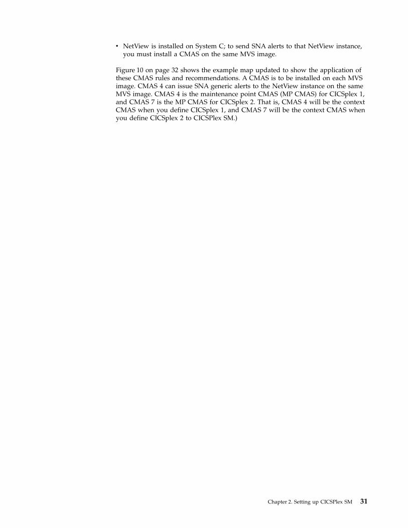
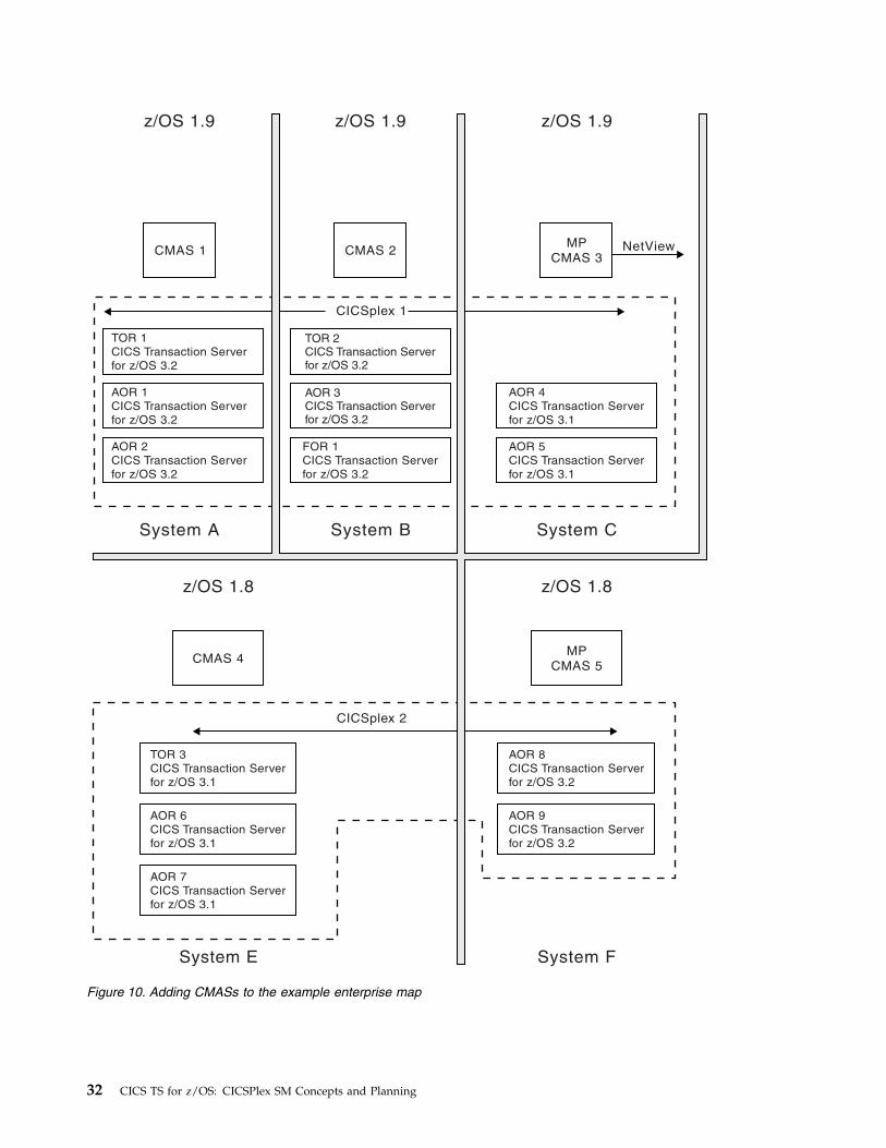
v NetView is installed on System C; to send SNA alerts to that NetView instance,you must install a CMAS on the same MVS image.
Figure 10 on page 32 shows the example map updated to show the application ofthese CMAS rules and recommendations. A CMAS is to be installed on each MVSimage. CMAS 4 can issue SNA generic alerts to the NetView instance on the sameMVS image. CMAS 4 is the maintenance point CMAS (MP CMAS) for CICSplex 1,and CMAS 7 is the MP CMAS for CICSplex 2. That is, CMAS 4 will be the contextCMAS when you define CICSplex 1, and CMAS 7 will be the context CMAS whenyou define CICSplex 2 to CICSPlex SM.)
Chapter 2. Setting up CICSPlex SM 31
FOR 1
CICS Transaction Server
for z/OS 3.2
AOR 4
CICS Transaction Server
for z/OS 3.1
AOR 8
CICS Transaction Server
for z/OS 3.2
AOR 9
CICS Transaction Server
for z/OS 3.2
TOR 3
CICS Transaction Server
for z/OS 3.1
AOR 6
CICS Transaction Server
for z/OS 3.1
AOR 7
CICS Transaction Server
for z/OS 3.1
AOR 5
CICS Transaction Server
for z/OS 3.1
AOR 1
CICS Transaction Server
for z/OS 3.2
TOR 1
CICS Transaction Server
for z/OS 3.2
AOR 2
CICS Transaction Server
for z/OS 3.2
TOR 2CICS Transaction Serverfor z/OS 3.2
AOR 3CICS Transaction Serverfor z/OS 3.2
CMAS 4MP
CMAS 5
CMAS 1 CMAS 2MP
CMAS 3
CICSplex 2
CICSplex 1
NetView
System FSystem E
z/OS 1.8z/OS 1.8
z/OS 1.9 z/OS 1.9 z/OS 1.9
System B System CSystem A
Figure 10. Adding CMASs to the example enterprise map
32 CICS TS for z/OS: CICSPlex SM Concepts and Planning

CMAS-to-CMAS linksWhen a CICSplex crosses multiple MVS images, multiple CMASs are likely to beinvolved in managing that CICSplex. The CMASs must be connected to each other(by using CICS intercommunication methods) so that data relating to the CICSsystems belonging to the CICSplex is accessible by all relevant CMASs, and asingle system image (SSI) can be presented to the CICS operator.
The minimum requirement is that CMASs managing the same CICSplexes belinked to form an open chain of CMASs, so that each CMAS is linked, if onlyindirectly, to every other CMAS. Meeting this requirement ensures that there is atleast one path from each CMAS to every other CMAS involved in managing thesame CICSplex. To achieve the best performance and availability, link every CMASdirectly to every other CMAS.
The links between multiple CMASs involved in managing the same CICSplex areresponsible for the SSI of the CICS systems or systems that belong to thatCICSplex. However, you do have a degree of choice regarding the number of linksyou define. First, here's a reminder of the rules and recommendations concerningCMAS-to-CMAS links:v To establish an SSI of a CICSplex, the CMASs managing that CICSplex should at
the very least be linked to form an open chain.v The more links you establish, the better the performance. The best performance
is achieved when every CMAS is directly connected to every other CMASinvolved in the management of a single CICSplex.
v A multiplicity of CMAS-to-CMAS links is also better for availability: if CMAS 1is at the end of the chain and is connected to CMAS 2 only, the failure of CMAS2 breaks the chain and leaves no connection to CMAS 1.
Figure 11 on page 34 illustrates the concept of direct and indirect CMAS-to-CMASlinks. This CICSplex comprises six CICS systems; three systems are managed byCMAS 1, and three systems are managed by CMAS 5. Without a direct linkbetween the two CMASs, CICSPlex SM can navigate dynamically around its“network” to gather information relevant to the CICSplex. It could go throughCMAS 4 or, if CMAS 4 is unavailable, it could go through CMAS 2 and CMAS 3.However, for optimum performance, a direct link should be added between CMAS1 and CMAS 5.
Chapter 2. Setting up CICSPlex SM 33

In the example enterprise configuration in Figure 12 on page 36, fullCMAS-to-CMAS connectivity is established for each of the two CICSplexes. That is,for management of CICSplex 1, CMASs 1, 2, 3 and 4 are directly connected to eachother; for management of CICSplex 2, CMASs 5, 6, and 7 are directly connected toeach other. Thus, the following CMAS-to-CMAS links must be defined:
CICSplex 1 CICSplex 2CMAS1 to CMAS2 CMAS5 to CMAS6CMAS1 to CMAS3 CMAS5 to CMAS7CMAS1 to CMAS4 CMAS6 to CMAS5CMAS2 to CMAS1 CMAS6 to CMAS7CMAS2 to CMAS3 CMAS7 to CMAS5CMAS2 to CMAS4 CMAS7 to CMAS6CMAS3 to CMAS1CMAS3 to CMAS2CMAS3 to CMAS4CMAS4 to CMAS1CMAS4 to CMAS2CMAS4 to CMAS3
If you decided to not link CMAS 1 to CMAS 3 directly, this arrangement wouldmeet the minimum CMAS-to-CMAS link requirement (by having an open chain ofCMASs) and you would need to define two less links. Some information would beobtained indirectly. For example, information requested from System C about CICSresources on System A would be obtained indirectly through the adjacent CMAS,CMAS 2. Wherever full connectivity is not established among a group of CMASs,CICSPlex SM works out the quickest route to the requested data dynamically.
The performance impact is slightly higher when information is obtained indirectly,but you must balance this against the overhead of setting up and maintaining the
Figure 11. CMAS-to-CMAS links in a CICSplex
34 CICS TS for z/OS: CICSPlex SM Concepts and Planning

CMAS-to-CMAS links. In fact, if the example enterprise configuration had oneCICSplex rather than two, full connectivity among the CMASs would be feasible.That is, you would need 42 CMAS-to-CMAS links, because the number of linksrequired is n² - n, where n is the number of CMASs to be connected. However, ifyou have ten CMASs managing a single CICSplex, the number of links required is90; for 15 CMASs,210 links. So you must decide how many direct links you areprepared to define, and where indirect links can be accommodated, alwaysremembering that the minimum requirement is for an open chain ofCMAS-to-CMAS links.
Figure 12 on page 36 shows the CMAS-to-CMAS links in the example enterpriseconfiguration. 18 links are defined, giving full connectivity among CMASsmanaging the same CICSplexes.
Chapter 2. Setting up CICSPlex SM 35

When there are multiple CMASs on the same MVS system, managing the sameCICSplex, a local MAS that specifies only the CICSPLEX(name) CICSPlex SMsystem parameter, and not the CMASSYSID(name) CICSPlex SM system parameter,
FOR 1
CICS Transaction Server
for z/OS 3.2
AOR 4
CICS Transaction Server
for z/OS 3.1
CICS/400 3.1
CICS/400 3.1
AOR 8
CICS Transaction Server
for z/OS 2.3
AOR 9
CICS Transaction Server
for z/OS 2.3
TOR 3
CICS Transaction Server
for z/OS 2.2
AOR 6
CICS Transaction Server
for z/OS 2.2
AOR 7
CICS Transaction Server
for z/OS 2.3
AOR 5
CICS Transaction Server
for z/OS 3.1
AOR 1
CICS Transaction Server
for z/OS 3.2
TOR 1
CICS Transaction Server
for z/OS 3.2
AOR 2
CICS Transaction Server
for z/OS 3.2
TOR 2CICS Transaction Serverfor z/OS 3.2
AOR 3CICS Transaction Serverfor z/OS 3.2
CMAS 4MP
CMAS 5
CMAS 1 CMAS 2MP
CMAS 3
CICSplex 2
CICSplex 1
NetView
System FSystem E
z/OS 1.2z/OS 1.2
z/OS 1.7 z/OS 1.7 z/OS 1.7 OS/400 3.1
System B System C System DSystem A
Figure 12. Adding CMAS-to-CMAS links to the example enterprise map
36 CICS TS for z/OS: CICSPlex SM Concepts and Planning

will connect to the last CMAS to initialize on the MVS image that manages thenamed CICSplex for a specific release of CICSPlex SM.
CMAS-to-CMAS links for multiple CICSplexes
The example enterprise configuration has two CICSplexes. To enable the CICSPlexSM operator to access CICSplex 2 data from System B, for example, you couldestablish a link between any one (or more) of the CMASs involved in managingCICSplex 1 and any one (or more) of the CMASs involved in managing CICSplex2. For example, you could establish a link from CMAS 1 to CMAS 5, thus forminga chain of all of the enterprise CMASs.
Locating the maintenance point CMASWhen a single CICSplex is managed by multiple CMASs, one of them isdesignated the maintenance point CMAS (MP CMAS).
The MP CMAS is responsible for maintaining all CICSPlex SM definitions relatingto a CICSplex, and for distributing up-to-date information to the other CMASsinvolved in managing the same CICSplex, so that no data repository is out of stepwith any other.
The MP CMAS is the CMAS that is the context value when the CICSplex is definedto CICSPlex SM. Each CICSplex can have only one MP CMAS, but a single CMAScan be the MP CMAS for more than one CICSplex. If the MP CMAS is unavailableat any time, no changes to any CICSPlex SM definitions can be made.
An MP CMAS can also function as a non-maintenance point CMAS for otherCICSplexes.
Note: The CICSPlex SM single point of control means that changes to the MPCMAS can be made from any system on which the CICSPlex SM WUI is available.
Ideally, connect the MP CMAS only to other CMASs and a Web User Interface(WUI) server. Do not connect the MP CMAS to other CICS regions. Thisconfiguration means that the MP CMAS can easily be moved between MVSimages, or have maintenance applied, without affecting other regions.
Planning the location of WUI serversThe location and number of WUI server regions in your enterprise depend on youravailability requirements and globalization support.
Before you begin
You must have planned where to install the CMASs and how to link them togetherbefore planning where to install the WUI server regions.
About this task
The WUI server is a CICS region that acts as a CICSPlex SM application, using theAPI to view and manage objects in the data repositories of CMASs.
Procedure1. Decide if you want a WUI server to be available in every MVS image. If you
have a WUI server on each MVS image, you do not have to connect the WUIservers directly to the CMAS on each MVS image.
Chapter 2. Setting up CICSPlex SM 37
||||

Tip: If you define a separate CICSplex for the WUI servers, the number ofCMAS maintenance points across your enterprise are kept to a minimum. Italso separates the WUI servers from statistics generated from CICSplexes thatare running CICS applications.
2. Decide what national languages the WUI must support. If you want to displaythe WUI in more than one language, you require a WUI server for eachlanguage.
3. Decide what connections are required from each WUI server region to theCMASs.v The CMAS to which the WUI server connects must be managing all the
CICSplexes to which the WUI server requires access. However, it is notnecessary for the CMAS to which the WUI connects to be managing any ofthe MASs in these CICSplexes.
v The CMAS and the WUI server that you want to connect must be at thesame release level of CICS Transaction Server.
4. Update your topology map to include the WUI server regions.
Example
On system F, a WUI server is connected to the maintenance point, CMAS 7, and isin a separate CICSplex called CICSplex 4. The WUI server and CMAS 7 are both atthe same level of CICS Transaction Server. CMAS 7 is the maintenance point forboth CICSplex 2 and CICSplex 4.
38 CICS TS for z/OS: CICSPlex SM Concepts and Planning

FOR 1
CICS Transaction Server
for z/OS 3.2
AOR 4
CICS Transaction Server
for z/OS 3.1
CICS/400 3.1
CICS/400 3.1
AOR 8
CICS Transaction Server
for z/OS 2.3
AOR 9
CICS Transaction Server
for z/OS 2.3
TOR 3
CICS Transaction Server
for z/OS 2.2
AOR 6
CICS Transaction Server
for z/OS 2.2
AOR 7
CICS Transaction Server
for z/OS 2.3
AOR 5
CICS Transaction Server
for z/OS 3.1
AOR 1
CICS Transaction Server
for z/OS 3.2
TOR 1
CICS Transaction Server
for z/OS 3.2
AOR 2
CICS Transaction Server
for z/OS 3.2
TOR 2CICS Transaction Serverfor z/OS 3.2
AOR 3CICS Transaction Serverfor z/OS 3.2
CMAS 4
MP
CMAS 5
CTS 2.3
WUI
Server
CTS 2.3
WUI Server
CTS 3.2
WUI
Server
WUI
Server
WUI
Server
CICSplex 4CAS
CMAS 1
CTS 3.2
CMAS 2
CTS 3.2
MP
CMAS 3
CTS 3.2
CICSplex 2
CICSplex 1
CICSplex 3
NetView
System FSystem E
z/OS 1.2z/OS 1.2
z/OS 1.7 z/OS 1.7 z/OS 1.7 OS/400 3.1
System B System C System DSystem A
Figure 13. Adding WUI servers to the example map
Chapter 2. Setting up CICSPlex SM 39

Naming your CICSPlex SM entitiesAll the entities that you have defined, and entered on to your CICSPlex SM map,have to be named. You must devise a convention for naming those entities that isboth meaningful and extendable.
The rules governing the naming of CICSPlex SM elements are as follows:v Each element name can be up to 8 characters.v The element name must begin with an alphabetic (or national) character, and
must have no embedded blanks. Subsequent characters can be alphabetic ornumeric.
v Names of CICSplexes and of CMASs must be unique in the enterprise.v Names of CICS systems and CICS system groups must be unique in the
CICSplex.v All other names must be unique for their type in the CICSplex.
The entity types, for each instance of which a name is required, are:v CICSPlex SM components and CICSplex entities
– CMAS, CICSplex, MAS (CICS system or WUI server), CICS system group,and time-period definition.
v BAS entities– Resource assignments, resource descriptions, resource definitions, and
resource groups.Application resource definitions are:- Db2 transactions, files, map sets, partition sets, programs, transient data
queues, transactions, CICS BTS process types, document templates, FEPInodes, FEPI pools, FEPI property sets, FEPI targets, file and key filesegment definitions, LIBRARY definitions, map sets, sysplex enqueuemodels, TCP/IP services, temporary storage models
Region resource definitions are:- Db2 entries, enterprise beans, journals, journal models, local shared
resource (LSR) pools, profiles, temporary storage queue models, transactionclasses, terminals, typeterms
System–system connectivity resource definitions are:- Connections, Db2 connections, IPIC connections, partners, sessions
v Monitor entities– Monitor definition, monitor group, and monitor specification
v Analysis entities– Analysis definition, analysis group, analysis point specification, analysis
specification, action definition, evaluation definition, and status definitionv Workload management entities
– Transaction group, workload definition, workload group, and workloadspecification.
Ensure that any convention you select can accommodate all of these entity types.
40 CICS TS for z/OS: CICSPlex SM Concepts and Planning

Generic names
CICSPlex SM supports the use of generic names in many of its commands. Forexample, you can specify that all transactions whose names begin with the letters“DNW” are monitored once every 300 seconds. You do not need to name eachtransaction individually.
The rules governing the use of generic names are as follows:v The asterisk character (*) can be used in place of one or more characters. It can
appear once only in any name, and must appear at the end of any partial string.For example, the string “DNW*” means all names beginning with the lettersDNW.
v The plus sign (+) can replace any single character and can occur in any positionin the name. For example, “DNW+++L” means any name of 7 characters startingwith the letters DNW and ending with the letter L.
A staged implementationIf you have a very large number of CICS systems, or if you have decided to createmultiple CICSplexes, you might want to consider implementing CICSPlex SM instages.
You can install CICSPlex SM on a subset of your systems and use it to manage asingle CICSplex or, if you have defined a single CICSplex for the enterprise, youcan use it to manage particular system groups. Additional CICS systems can beadded to the configuration gradually.
If you opt for the gradual approach, you will need to revisit your final map of theenterprise CICS systems and identify those you plan to start with. For example, ifa staged implementation were adopted for your example map, you could decide tobegin by implementing CICSplex 2 only. The CMAS-to-CMAS links would bemuch reduced in number (six CMAS-to-CMAS links, rather than 18), but the otherdecisions made about CICSplex 2 are still valid. That is, the same CICS systemgroups can be defined, and the CMAS installations are still required.
Planning CICSPlex SM setupCICSPlex SM is installed as part of the product. To set up CICSPlex SM you mustplan the security that is required, and which time zones to use in the CICSplex.
To implement CICSPlex SM in your existing environment, you can use the samplesthat are supplied with CICS to get started.
Security planning for CICSPlex SMCICSPlex SM uses a SAF-compliant external security manager, such as RACF® toprevent unauthorized access to CICSPlex SM functions and CICS resources, and tocontrol the simulation of CICS command checking and CICS resource checking.
In both cases, security checking is handled by the CMASs managing the CICSsystems that are the target of any request to access a resource. For example, if aCICSplex is managed by two CMASs, and a request is made to access a resource inall CICS systems belonging to that CICSplex, the security check is performed inboth CMASs.
Chapter 2. Setting up CICSPlex SM 41

To activate security checking, you must modify the JCL used to start the CMAS orits managed CICS systems. If security checking is switched off for the CICSsystem, no checking occurs, regardless of the CMAS setting. However, if securitychecking is switched off for the CMAS but switched on for the CICS system, theCICS system is not able to connect to the CMAS.
Begin by deciding how much security checking you need. In particular, identifythose users who need access to CICSPlex SM, and ensure that an individual userhas the same user ID across all systems on which a CMAS is installed. The user IDagainst which the security check is performed is the RACF ID that has been usedto sign on to CICSPlex SM. Consider also the type of security checking you wantto implement.
See Implementing CICSPlex SM security for more information about how to set upCICSPlex SM security.
Protecting access to CICSPlex SM functions and CICS resources
To prevent unauthorized access, you create security profiles for combinations ofCICSPlex SM functions, and CICS resources that are to be protected. In most cases,the security provided by CICSPlex SM security profiles is adequate.
An external security manager is also used to protect CICSPlex SM libraries,procedures and Web User Interface resources. Full details of how to protectCICSPlex SM libraries and procedures are provided in Implementing CICSPlex SMsecurity. In order to protect Web User Interface views, menus, help informationand the View Editor, you need to create an appropriate profile in the FACILITYclass. See Controlling access to Web User Interface resources for more information.
Special considerations for BAS
Take special care in the protection of the BAS views, so that unauthorized userscannot create and administer resources. The equivalent in RDO terms is leavingyour CSD unprotected.
Also take care if you use the EXEC CICS CREATE command to build new resources.Any definition created with the CICSplex as the context is automaticallydistributed to all CMASs in the CICSplex. Therefore, giving a user authority tocreate BAS objects is equivalent to giving authority to install resources on anyCICS system in the CICSplex. When the CICS system starts, there is no check onwho installed the resource in the system.
CICS command and resource checking
CICS command and resource checking is simulated by CICSPlex SM in the CMASsto which a request is directed. This allows you to protect CICS systems that do notsupport your external security manager. It also allows for a level of consolidationof your security checking.
Determine where CICS resource and command checking is in effect, and decidewhether it needs to be retained along with other CICSPlex SM security checking.
Defining time zonesMuch of the activity of CICSPlex SM is time dependent.
42 CICS TS for z/OS: CICSPlex SM Concepts and Planning
For example, you can specify that a monitor definition or an analysis definition isto be active during a particular time period. CICSPlex SM does not require everyMAS in a single CICSplex to be running in the same time zone, and so must beable to accommodate any time-zone differences between entities. Therefore:v Whenever you create a time-period definition (using the CICSPlex SM Time
period definitions view), you must specify a time zone in the definition.Forexample, you could create a time-period definition called “MORNING” for thehours 0800 through 1159 Eastern standard time.
v You must specify a time zone for each CMAS in its data-repository initializationjob, EYU9XDUT. A permanent change to the CMAS time-zone value can bemade, even while the CMAS is running, via the CICSPlex SM Web UserInterface.
v A time zone must be established for each managed CICS system. When youdefine a CICS system to CICSPlex SM, you can specify the time zone in whichthe system is running. Alternatively, if you don't specify a time zone in the CICSsystem definition, the CICS system is assumed to be running in the time zonethat is the default for the CMAS to which it connects. You are recommended toallow the time zone of a managed CICS system to default to that of its CMAS.The time zone of a managed CICS system can be altered subsequently while theCICS system is running. Any change made in this way lasts for the lifetime ofthe CICS system, or until it is next changed, whichever is sooner.
v A time zone must be specified for every CICSplex when it is first defined. Thistime zone is used by the CICSPlex SM monitor function to determine the actualtime at which the monitor interval for the CICSplex expires. The CICSplex timezone can be altered via the CICSPlex SM end-user interface.
Time zones are specified using single-character codes in the range B through Z. Forexample, code “S” represents Mountain Standard Time, code “T” representsCentral Standard Time, and code “C” represents Eastern Europe time. For acomplete list of the codes, see Time zone setting in a period definition. CICSPlexSM allows offsets (known as “time zone adjustments”) in the range 0 through 59minutes to be specified to accommodate regions that are not running in thestandard time zones. Also, daylight saving time can be specified.
Because multiple CICSPlex SM entities require a time zone to be specified, there isobvious potential for “conflicting” time-zones to be specified. For example, it isquite possible that a CMAS and a MAS in the same CICSplex could be in differenttime zones. CICSPlex SM always honors the time zone of the MAS. For example,if:v The time-period definition time zone is S
andv The CMAS time zone is B
andv The MAS time zone is C
time zone C is used by the MAS, and the CMAS makes any necessary adjustmentsbetween time zones B, C, and S to ensure that the time zone is honored.
Reuse of CICSPlex SM object definitionsCICS does not provide identical support for resources and functions across all ofits platforms or releases.
Chapter 2. Setting up CICSPlex SM 43

For example, a resource, such as FEPI, that is supported in the CICS TSenvironment might not be supported on other platforms. Similarly, the amount ortype of data available for a resource can vary among CICS platforms and releases.These variations in support pose a special challenge to CICSPlex SM, which offersa SSI of multiple and varied CICS systems.
Here are some examples that illustrate how CICSPlex SM handles variations insupport for resources and functions throughout a CICSplex that includes CICSTS.systems.v Example 1: monitoring of transient data queues
You create a monitor definition for transient data queues, add it to a monitorgroup, and associate the monitor group with a monitor specification. The scopeof the monitor specification is every CICS system in the CICSplex. As each CICSsystem starts, CICSPlex SM determines whether it can install the monitordefinition in that system. If not, CICSPlex SM issues a message to inform youthat the monitor definition could not be installed. Both the monitor function andtransient data queue resources are supported underCICS TS, so CICSPlex SMinstalls the monitor definition in those environments and monitoring begins.
v Example 2: RTA of monitored programs
You create an evaluation definition and name MPROGRAM (monitoredprograms) as the resource to be evaluated by theCICSPlex SM RTA function. Theevaluation definition is named in an analysis definition, which is linked, via ananalysis group, to an analysis specification. The scope of the analysisspecification is every CICS system in the CICSplex. The analysis definition isinstalled in the CICS TS systems. If an analysis definition names multipleevaluation definitions, CICSPlex SM installs those that are supported in thetarget environment.
In summary, if you request a function that isn't available in a particular CICSenvironment, CICSPlex SM issues a warning message. You do not have to respondto the message and, more importantly, you do not have to take variations insupport into account when creating CICSPlex SM object definitions: you shouldalways consider CICSPlex SM object definitions to be reusable.
Defining the CICSPlex SM configuration and topologyOnce CICSPlex SM has been installed, and you have a map of your CICSPlex SMenvironment, you can define the configuration and topology.
Defining the CMAS configurationFor each CMAS you have defined, you must provide certain information toCICSPlex SM.
The following information must be provided:v The name of each CICSplex that it is to manage, if it is a maintenance-point
CMASv Link definitions for each CMAS to which it is connected
To enter this information, you can use the appropriate CMAS configurationadministration views, accessed from the CMAS configuration administrationmenu, or the batched repository-update facility.
44 CICS TS for z/OS: CICSPlex SM Concepts and Planning

Managing the CMAS configurationThe following WUI view sets and related objects are used to manage your CMASconfiguration:
Table 1. View sets for managing your CMAS configuration
WUI view set Object name Description
Batchedrepository-updaterequests
BATCHREP To create, update, remove, list, or dump oneor more definitions from the data repositoryassociated with the local CMAS.
CMAS to CMAS linkdefinitions
CMTCMDEF To display information about the directLU6.2 and MRO communication linksbetween the local CMAS and any otherCMASs.
CICSplex definitions CPLEXDEF To define a CICSplex to the local CMASand to administer CICSplex definitions forthe local CMAS.
CMAS in CICSplexdefinitions
CPLXCMAS To administer information about CMASsassociated with a CICSplex, where the localCMAS is the maintenance point for thatCICSplex.
CICSPlex SM also provides the following WUI view sets and resource objects thatyou can use to manage CMAS configuration definitions when the associatedCMASs are active.
Table 2. View sets for managing active CMASs
WUI view set Object name Description
CMASs managingCICSplex
CICSPLEX To display information about the CMASsassociated with a CICSplex known to thelocal CMAS.
CMASs known tolocal CMAS
CMAS To display information about CMASsknown to the local CMAS, shut down aCMAS, and alter CMAS component tracesettings.
CICSplexes managedby CMAS
CMASPLEX To display information about theCICSplexes being managed by the localCMAS and to remove the CMAS frommanaging CICSplexes when the MPSTATEis INVALID or NOTCONNECTED.
CMAS to CMAS links CMTCMLNK To display information about all or specificCMASs linked to the local CMAS and todiscard a CMAS-to-CMAS link.
CMAS to MAS links CMTPMLNK To display information about all or specificMASs linked to the local CMAS and todiscard the CMAS-to-MAS link.
Defining CICSplex topologyWhen you have identified your CICSplexes and MASs, you need to create thedefinition objects that will identify them to CICSPlex SM. You should be awarethat you will not have all the information required at this point; more informationwill emerge as the design of your CICSPlex SM system proceeds.
Chapter 2. Setting up CICSPlex SM 45

More information about designing CICSplexes is given in “Designing yourCICSplexes” on page 22
Preparing CICSplex definitionsEach CICSplex must be defined to CICSPlex SM by a name that is unique withinthe enterprise.
Naming conventions are given in “Naming your CICSPlex SM entities” on page 40.You also should be aware that you will need other information for the CICSplexdefinition, which will become available as you proceed with the design of yourCICSPlex SM system. This information includes:v The name of the CMAS to which the CICSplex is to be defined. (This is the
maintenance point CMAS for the CICSplex.)v The names of any other CMASs that are to participate in management of the
CICSplex.v A time zone for the CICSPlex SM monitor function.v Whether CICS command checking is to be simulated.v Whether CICS resource checking is to be simulated.
Managing the CICSplex definitions:
You identify a CICSplex identified to CICSPlex SM with the CICSplex definitionsview (CPLEXDEF object).
.
To enter this information, you can use either the appropriate CMAS configurationadministration views, accessed from the CMAS configuration administrationmenu, or the batched repository-update facility.
When you have created a CICSplex definition, you can associate CICS systems(MASs) and CICS system groups with the CICSplex. See “Planning CICS systemdefinitions.”
Planning CICS system definitionsTo manage a CICS region with CICSPlex SM, you must associate the CICS regionwith a CICSplex that is defined to CICSPlex SM. The definition that establishes thisassociation also contains information about how the CICS system is to use theBAS, WLM, RTA, and monitoring components of CICSPlex SM.
About this task
For every CICS region that is to be managed by CICSPlex SM, you must gather thefollowing information:
Procedure1. Gather the basic information about your CICS region to create a definition.
a. Decide the name by which this CICS region is to be known to CICSPlex SM.This name can be up to 8 characters in length.
b. Find the APPLID, that is, the z/OS Communications Server applicationidentifier of the CICS region.
c. Find the SYSID, that is, the CICS system identifier of the CICS region.
46 CICS TS for z/OS: CICSPlex SM Concepts and Planning

This information is sufficient to add the definition to the data repository. If youhave special BAS, WLM, RTA, or monitoring requirements for any CICS region,you can gather the information before adding the definition or update thedefinition later.
2. Optional: Gather additional information about your CICS region for thedefinition.a. If you are implementing system availability monitoring (SAM), find the
name of the primary CMAS and the hours of operation of the CICS region.The primary CMAS is the CMAS that the CICS region usually connects to.
b. Decide whether or not to simulate CICS command checking.c. Decide whether or not to simulate CICS resource checking.d. Decide what types of connections are required to other CICS regions and
how many sessions to allow on each connection. If you want to create IPinterconnectivity (IPIC) connections, you must also the port number, thehost name, and network ID of the CICS region.
e. Decide what time zone of the CICS region is to use, if it is not to be thesame as that of its CMAS.
What to do next
When you have gathered the information necessary to create a system definition,you can use the CICS Explorer or the Topology administration views in the WebUser Interface to create the definition in the data repository.
Preparing CICS system group definitions:
For each CICS system group to be defined to CICSPlex SM, you need provide onlya name for the group, which may be unique within the CICSplex.
The CICS system group must be defined before you can add CICS systems to it. Todefine a CICS system group, you use the Topology administration (ADMTOPOL)views.
Defining CICS system groups, perhaps more than any other part of the designstage, is an iterative process and a cumulative one. It might be obvious to youalready that there are natural groupings of CICS systems within your CICSplexes,and that you will want to manipulate each of those groups as a single entity. If thisis the case, start to document the groups now. Because groups do not have to bemutually exclusive, and because a CICS system can belong to any number ofgroups, you can add CICS system group definitions as new requirements emerge.
To create CICS system groups, you use the System group definitions view(CSYSGRP object).
You can display information about the CICS system groups, and the CICS systemsassociated with them, that are known to the CICSplex identified as the currentcontext, by using the System group definitions view (CSYSGRP object).
CICS system definition views:
The Web User Interface provides a number of views to help you define, install, andmanage CICS system definitions. You can also use the CICS Explorer to performthe same tasks.
These views are described in detail in CPSM administration views.
Chapter 2. Setting up CICSPlex SM 47

Table 3. View sets to manage CICS system definitions
WUI view set Object name Description
ISC/MRO connectiondefinitions
CONNDEF To create and administer connectiondefinitions that identify remote systems thata CICS region communicates with usingintersystem communication (ISC) ormultiple region operation (MRO).
CICS systemdefinitions
CSYSDEF To create and administer the definition thatassociates a CICS system with a CICSplex.The definition also contains informationabout how the CICS system is to use theWLM, real-time analysis, resourcemonitoring, and business applicationservices components of CICSPlex SM.
System groupdefinitions
CSYSGRP To create and administer CICS systemgroups within a CICSplex, including addingCICS regions to CICS system groups.
IPIC connectiondefinitions
IPCONDEF To create and administer TCP/IPconnection definitions that describe theoutbound attributes of connections betweenCICS regions that communicate using IPinterconnectivity (IPIC) connections.
Time perioddefinitions
PERIODEF To create and administer time perioddefinitions, which identify specific ranges ofhours and minutes to be used with resourcemonitoring and real-time analysis.
Session definitions SESSDEF To create and administer session definitionsthat describe the nature of logicalconnections between regions thatcommunicate using intersystemcommunication (ISC) or multiple regionoperation (MRO).
CICS system links SYSLINK To create and administer the links betweenCICS regions in the CICSplex.
TCP/IP servicedefinitions
TCPIPS To create and administer TCP/IPconnection definitions that describe theinbound attributes of connections betweenCICS regions.
CICSPlex SM provides the Runtime MAS display (MAS) view set that you canuse to manage configuration definitions when the associated CICS regions areactive.
48 CICS TS for z/OS: CICSPlex SM Concepts and Planning

Table 4. View set to manage configuration definitions in an active CICS region
WUI view set Object name Description
Runtime MAS display MAS To manage information about active CICSregions known to a CICSplex or connectedto the designated CMAS involved inmanaging the CICSplex.
v Display information about the activeCICS regions
v Browse or temporarily update thegeneral, WLM, real-time analysis,resource monitoring, and MAS traceattributes of an active CICS region.
v Stop MAS agent code in an active CICSregion.
Note: Using the CICS system definitions view (CSYSDEF object) and the Timeperiod definitions view (PERIODEF object) to update definitions affects both acurrently running system and the definitions in the data repository. Updates madeusing the Runtime MAS display view (MAS object), however, are not included inthe data repository.
Where next?You have a working CICSPlex SM environment, with your configuration andtopology defined, and with the links between the entities defined.
The entities can communicate with each other and you can run transactions.However, to optimize the operation of your enterprise and to take full advantageof the facilities offered by CICSPlex SM, you need to set up your BAS, WLM, RTA,and monitoring requirements. For guidance, go to Managing resources usingBusiness Application Services (BAS), Managing workloads, Monitoring usingreal-time analysis (RTA), or Collecting statistics using CICSPlex SM monitoring, asappropriate.
Setting up a CICSPlex SM address space (CMAS)Perform these steps to make a CICSPlex SM address space (CMAS) operational.
For a summary of the CMAS setup tasks that you use while performing them, seeCICSPlex SM setup checklist and worksheets.
Before you set up a CMASCheck your initialization values, changes between releases, release levelcompatibility and maintenance you might need to apply to your system.
Check the considerations for setting up CMAS, described in “Designing yourCICSPlex SM environment” on page 21.
Check the IEASYSxx member of SYS1.PARMLIB that you use for MVS initializationand make note of the initialization values that are referenced during installation.For details about the initialization values, see Noting IEASYSxx values forCICSPlex SM.
Chapter 2. Setting up CICSPlex SM 49

If you are converting your CICSPlex SM system or systems from a previousrelease to CICSPlex SM for CICS TS for z/OS, Version 5.5 open beta, read theupgrading information for your level of CICSPlex SM.
A CICSPlex SM CMAS runs only in a CICS system at the same release level. Forexample, a CICS TS 5.5 open beta CMAS runs only in a CICS TS 5.5 open betaregion. During startup, the CMAS checks the CICS release level and ends withmessage EYUXL0142 if the releases do not match. Managed CICS systems do nothave the same restriction.
For details about applying corrective or preventive maintenance to CICSPlex SM,see .
Note the information in CICSPlex SM address space (CMAS) about appropriateuses of a CMAS.
CICSPlex SM auxiliary storage usageWhen a CMAS is initialized, a number of MVS data spaces are created.
CICSPlex SM uses these data spaces to allow quick access to data from a CMASand the MASs attached to it. Although the data spaces are logically owned by theCMAS, they are physically owned by the ESSS address space (EYUX550). The dataspaces are deleted when the CMAS that logically owns the data spaces, and alllocal MASs, and batch jobs, that are attached to that CMAS are stopped. The dataspaces are re-created when the CMAS is initialized again.
The number of data spaces created depends on the CACHEDSNUM value for theCMAS. This setting controls the number of data spaces allocated for eachcomponent, except the data cache manager, which has only one data space.Therefore, the number of SCOPE=ALL data spaces required for a CMAS can becalculated as follows:
number of SCOPE=ALL data spaces = ( 9 * CACHEDSNUM ) + 1
The default value of the CACHEDSNUM parameter is 2, and normally you do notchange it unless advised to do so by IBM Support. Therefore, each CMAS typicallyrequires 19 SCOPE=ALL data spaces.
The size of the data spaces depends on the amount of work (such as end-userinterface, workload management, MAS resource monitoring, and real-time analysisprocessing) that the CMAS is performing, and the number of MASs connected tothe CMAS. The size ranges from 20 MB of storage in a relatively idle CICSPlex SMconfiguration to well over 100 MB of storage in a configuration that is complex inboth the number of MASs and the amount of work requested. If you do notprepare for such an increase in storage usage, you might encounter auxiliarystorage shortages when you first start to use CICSPlex SM.
To avoid such auxiliary storage shortages, ensure that your auxiliary storage canhandle an increase of 100 MB of storage in the environment. Additionally, you canmonitor the CICSPlex SM data space use by using an external monitor package todetermine the amount of storage the EYUX550 job uses.
If you contact IBM support personnel because of auxiliary storage shortages, youmight be asked to use CICSPlex SM online debugging transactions (COD0 and
50 CICS TS for z/OS: CICSPlex SM Concepts and Planning

CODB) to evaluate the storage use of EYUX550. For information about the COD0and CODB transactions, see Using the interactive debugging transactions (COD0and CODB).
If auxiliary storage shortages do occur, you can alleviate the problem by eitherdynamically increasing your auxiliary storage capability, or causing CICSPlex SMto free the allocated data spaces:1. To dynamically increase auxiliary storage capacity, allocate an additional page
data set, then use the MVS console command PAGEADD to make the newpage data set available.
2. To cause CICSPlex SM to free the allocated data spaces, first stop the CICSPlexSM agent in all local MASs connected to the CMAS. To stop the agent, use theCOSH transaction for each MAS or, if the MAS is a WUI server, use the COVCand COSH transactions.If a local MAS is acting as a CICSPlex SM WLM TOR, and the DTR program isspecified as EYU9XLOP for that MAS, you must change the DTR program fromEYU9XLOP before you can use the COSH transaction against that MAS. Forexample, you can change it to the IBM default program DFHDYP.
3. After the CICSPlex SM agent is stopped in all local MASs, stop the CMAS itselfusing the COSD transaction.
4. After the auxiliary storage capability is increased, you can restart the CMAS. Toreconnect any local MASs that remained active after the CICSPlex SM agentwas stopped, run the COLM transaction in those CICS regions.
You can run COLM using a modify command from the CONSOLE.
Preparing to transmit generic alerts to IBM Tivoli NetViewYou can have the real-time analysis (RTA) component of CICSPlex SM transmitgeneric alerts to an IBM Tivoli® NetView system when one or more user-definedconditions occur during analysis.
To be sure that an IBM Tivoli NetView system is ready to receive the alerts, use theNPDA command:
DFILTER AREC
This command verifies that the Event Type record IMPD is being passed to theIBM Tivoli NetView database in the IBM Tivoli NetView system.
The resulting list shows an ACTION of PASS for ETYPES of IMPD and RSLV.
If you need to add these record types to the filter, you can issue the followingNPDA commands:
SRFILTER AREC PASS E IMPDSRFILTER AREC PASS E RSLV
If the name of the IBM Tivoli NetView Alert Receiver has been changed from thedefault value (NETVALRT), you can use the CICSPlex SM system parameterALERTRCVR to specify the required name. See “CICSPlex SM system parameters”on page 129 for details of the ALERTRCVR parameter.
Preparing to start a CMASYou can start a CICSPlex SM address space (CMAS) during the IPL of an MVSsystem, from the system console, or as a batch job.
Chapter 2. Setting up CICSPlex SM 51

v To start a CMAS during the IPL of an MVS system, complete the followingsteps:– Verify that the CMAS startup procedure is in a system procedure library, such
as SYS1.PROCLIB.– Verify that the CMAS startup procedure is in the 'Started Tasks' table of the
external security manager (ESM).– Change the COMMNDaa member that is referenced by the IEASYSxx
member of SYS1.PARMLIB, as described in Noting IEASYSxx values forCICSPlex SM, to include a START command for the CMAS.The START command to be included is described in “START command for aCMAS” on page 68.
v To start a CMAS from the system console, complete the following steps:– Verify that the CMAS startup procedure is in a system procedure library, such
as SYS1.PROCLIB.– Verify that the CMAS startup procedure is in the 'Started Tasks' table of the
external security manager (ESM).– Have the operator issue the START command described in “START command
for a CMAS” on page 68.v To start a CMAS as a batch job, complete the following steps:
– Verify that the CMAS startup procedure is in a system procedure library, suchas SYS1.PROCLIB.
– Construct a job stream to invoke the CMAS procedure.– Submit the job to invoke a CMAS.
Whichever method you use to start a CMAS, you must verify that the procedurereferences the appropriate parameters:v CICS SIT parameters, as described in “CMAS-related CICS system initialization
parameters” on page 62.v CICSPlex SM startup parameters, as described in “CICSPlex SM system
parameters” on page 129.
The purpose of the CMAS is to manage a CICSPlex SM managed applicationsystem (MAS), so it is important that the CMAS runs at a higher dispatchingpriority than any MAS in the sysplex. The CMAS communicates with otherCMASs that it is connected to; these CMASs need to run at an equal dispatchingpriority, so that a CMAS on one LPAR does not process and send information outfaster than other CMASs that need to receive that data. Therefore, define theCMAS jobs to the MVS service class SYSSTC. Failure to do so can result in severeperformance problems for CICSPlex SM.
After you start a CMAS for the first time, you must configure the CMAS to yourenvironment. This configuration includes establishing the CICSplexes that theCMAS is to manage, and any communication links that are required between thisCMAS and another CMAS.
A sample procedure that you can use to start a CMAS is supplied in theEYUCMASP member. This member was generated when you ran the DFHISTARjob. The member is stored in the library that you specified on the LIB parameter ofthe DFHISTAR job.
52 CICS TS for z/OS: CICSPlex SM Concepts and Planning
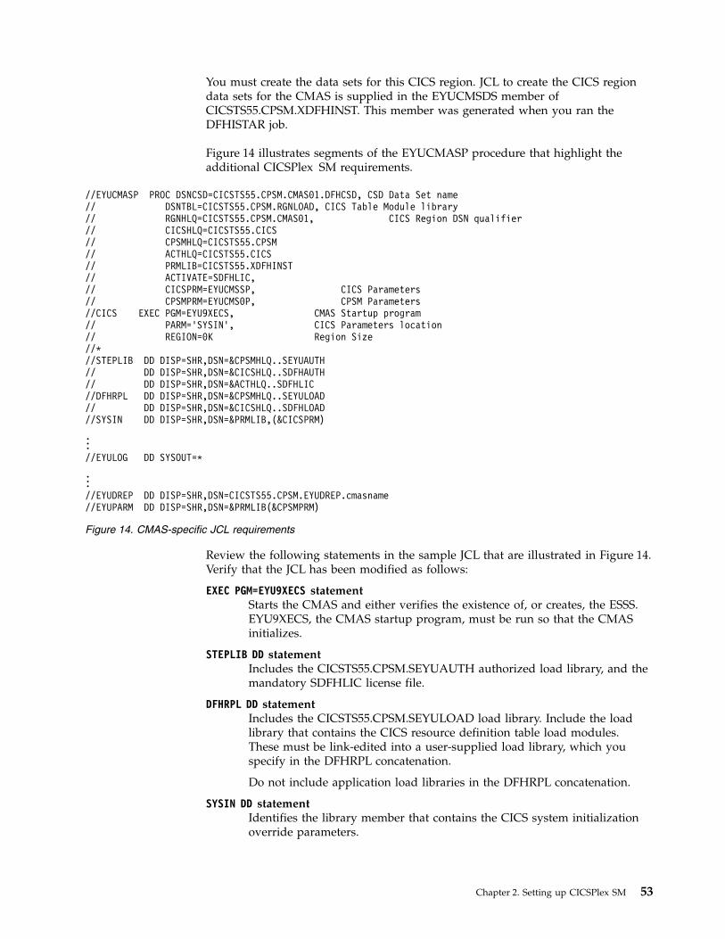
You must create the data sets for this CICS region. JCL to create the CICS regiondata sets for the CMAS is supplied in the EYUCMSDS member ofCICSTS55.CPSM.XDFHINST. This member was generated when you ran theDFHISTAR job.
Figure 14 illustrates segments of the EYUCMASP procedure that highlight theadditional CICSPlex SM requirements.
Review the following statements in the sample JCL that are illustrated in Figure 14.Verify that the JCL has been modified as follows:
EXEC PGM=EYU9XECS statementStarts the CMAS and either verifies the existence of, or creates, the ESSS.EYU9XECS, the CMAS startup program, must be run so that the CMASinitializes.
STEPLIB DD statement Includes the CICSTS55.CPSM.SEYUAUTH authorized load library, and themandatory SDFHLIC license file.
DFHRPL DD statement Includes the CICSTS55.CPSM.SEYULOAD load library. Include the loadlibrary that contains the CICS resource definition table load modules.These must be link-edited into a user-supplied load library, which youspecify in the DFHRPL concatenation.
Do not include application load libraries in the DFHRPL concatenation.
SYSIN DD statementIdentifies the library member that contains the CICS system initializationoverride parameters.
//EYUCMASP PROC DSNCSD=CICSTS55.CPSM.CMAS01.DFHCSD, CSD Data Set name// DSNTBL=CICSTS55.CPSM.RGNLOAD, CICS Table Module library// RGNHLQ=CICSTS55.CPSM.CMAS01, CICS Region DSN qualifier// CICSHLQ=CICSTS55.CICS// CPSMHLQ=CICSTS55.CPSM// ACTHLQ=CICSTS55.CICS// PRMLIB=CICSTS55.XDFHINST// ACTIVATE=SDFHLIC,// CICSPRM=EYUCMSSP, CICS Parameters// CPSMPRM=EYUCMS0P, CPSM Parameters//CICS EXEC PGM=EYU9XECS, CMAS Startup program// PARM=’SYSIN’, CICS Parameters location// REGION=0K Region Size//*//STEPLIB DD DISP=SHR,DSN=&CPSMHLQ..SEYUAUTH// DD DISP=SHR,DSN=&CICSHLQ..SDFHAUTH// DD DISP=SHR,DSN=&ACTHLQ..SDFHLIC//DFHRPL DD DISP=SHR,DSN=&CPSMHLQ..SEYULOAD// DD DISP=SHR,DSN=&CICSHLQ..SDFHLOAD//SYSIN DD DISP=SHR,DSN=&PRMLIB,(&CICSPRM)
...//EYULOG DD SYSOUT=*
...//EYUDREP DD DISP=SHR,DSN=CICSTS55.CPSM.EYUDREP.cmasname//EYUPARM DD DISP=SHR,DSN=&PRMLIB(&CPSMPRM)
Figure 14. CMAS-specific JCL requirements
Chapter 2. Setting up CICSPlex SM 53

EYULOG DD statement Identifies the log to which messages from the CMAS and its associatedmanaged application systems (MASs) are to be directed.
When you are using a sequential data set for the EYULOG, allocate threeprimary cylinders and one secondary cylinder.
EYUDREP DD statement Identifies the library to be used as the data repository by the CMAS, wherecmasname is the name you specified for the CMASNAME parameter on theDFHISTAR job. The CMASNAME value is used by EYU9XDUT to createthe CICSPlex SM data repository.
EYUPARM DD statement Identifies the library that contains the CICSPlex SM system parameters.
Creating and managing the CICSPlex SM data repositoryUse the EYUCMSDS postinstallation job to create the CICSPlex SM data sets. TheEYUCMSDS job is generated when you run the DFHISTAR job.
CICSPlex SM postinstallation members describes how to create a simple CICSPlexSM configuration. The EYUCMSDS job is stored in the library that you specifiedon the LIB parameter of the DFHISTAR job.
The alternate data repository file definition, EYUDREPN, is used by the CMAS insituations where logging are not needed. The current functions that bypass loggingare importing or adding a CICSplex, and removing or deleting a CICSplex. Inthese situations, no backout is necessary, therefore no logging is required. Do notmodify the recovery attributes of the EYUDREPN file definition.
The EYUDREP file definition is created dynamically during PLTPI by EYU9XLCDin the CMAS and specifies attribute LSRPOOLID(1). The CMAS does not createLSRPOOL 1, and if it does not exist, CICS file control DFHFCL calculates the sizeof LSRPOOL 1 and dynamically creates it when the EYUDREP is first opened inthe CMAS. You can choose instead to define your own specifications for LSRPOOL1 in the DFHCSD. If you choose to define your own LSRPOOL 1, monitorLSRPOOL 1 usage statistics to ensure adequate performance for the CMAS.
Creating the CICSPlex SM data repositoryThe CMAS-related data set is the data repository. Each CMAS must have a uniquedata repository associated with it. The data repository contains the CICSPlex SMadministration definitions applicable to its associated CMAS.
The data repository is a critical component of CICSPlex SM system management.You must take regular backups that are associated with each CMAS in yourenvironment.
The data repository is defined to CICS as being a recoverable file that participatesin SYNCPOINT and SYNCPOINT ROLLBACK operations. The CMAS must have aCICS system log so that these operations work correctly. Therefore, do not run aCMAS with a system log that is defined as type DUMMY because you willcompromise data integrity on the CICSPlex SM data repository.
To create the data set that contains the data repository, you can use theEYUCMSDS postinstallation job.
54 CICS TS for z/OS: CICSPlex SM Concepts and Planning

If you are running multiple CMASs in the same MVS image, you must create adata repository for each CMAS. You can edit and resubmit the DFHISTAR job,which generates the EYUCMSDS postinstallation job.
To ensure that you do not overwrite your existing customized jobs, you can usethe SELECT parameter, as described in “Setting up a CICSPlex SM address space(CMAS)” on page 49. Alternatively, if you prefer not to resubmit DFHISTAR, youcan edit the EYUCMSDS job, giving the SYSIDNT and CMASNAME parametersunique names each time you run the job.
Note: If you run the DREPCNVT step to upgrade an existing CMAS DREP to thelatest version, use the DREP dataset itself as input and not a copy of it. Otherwise,CMAS isolation issues might occur when the CMAS is restarted.
The EYUCMSDS job includes the following steps that relate to creating the datarepository:
DELDREPThis step deletes the data repository set. It allows you to resubmit the job.
DEFDREPThis step allocates the VSAM KSDS cluster for the data repository data set:
dsindex.EYUDREP.cmasname
dsindexIs defined by the DSINFO parameter of the DFHISTAR job.
cmasnameIs defined by the CMASNAME parameter of the DFHISTAR job.
CICSPlex SM does not support VSAM records that span control intervals.Make sure that the IDCAMS job that you use to create a CICSPlex SM datarepository does not specify the SPANNED parameter. Accept the IDCAMSdefault of nonspanned records.
DREPINITThis step is used to set up the data repository for a CICS TS for z/OS,Version 5.5 open beta CMAS.
The DREPINIT step is generated in the EYUCMSDS job if you did notspecify a value with the OLDDREP parameter when you ran theDFHISTAR job. This step runs EYU9XDUT to initialize the new datarepository that was allocated by step DREPALOC. The new data repositorydoes not contain any records from a previous version of CICSPlex SM. TheEYU9XDUT utility uses the following parameters for step DREPINIT:
CMASNAME=xxxxxxxx
v You cannot change this name after the data repository isinitialized.
v This name must be unique in the CICSPlex SM environment. Donot use the same name as that of another CMAS, a CICSplex, aCICS system, or a CICS system group.
v Position 1 must be alphabetic or national, and cannot benumeric.
v Positions 2 through 8 can be alphabetic, national, or numeric.
SYSID=xxxx
v You cannot change this identifier after the data repository isinitialized.
Chapter 2. Setting up CICSPlex SM 55

v This value must match the SYSIDNT (SIT parameter) for theCMAS; see “CMAS-related CICS system initializationparameters” on page 62.
v This value must not be the same as the SYSID for any otherCMAS or CICS system that is defined to CICSPlex SM.
v Positions 1 through 4 can be alphabetic, national, or numeric.
TIMEZONE=xx must be a single alphabetic character (B through Z), representingone of the Greenwich time zone codes.
ZONEOFFSET=nnnn must be a two-digit numeric value (00 through 59), representingan adjustment (offset) to the TIMEZONE.
DAYLIGHT=xx must be a single character (Y or N), representing daylight savingtime.
The DREPINIT step requires a DD statement for EYUXDPRM, which setsup the WUI parameters:
WUI=YES|NOThe default of WUI=YES creates the CICSPlex SM resourcedefinitions required to start a WUI server and its CICSplex.Thisparameter allows you to create the resource definitions required tostart a WUI server and its CICSplex when you create the datarepository. To add a WUI to an existing system, use theEYU9XDBT or BATCHREP utilities.
WUIAPPLID=xxxxxxxxxxxxxxxx must be alphabetic, national, or numeric characters,specifying the APPLID allocated to a WUI. The first character mustbe alphabetic or national. This parameter is mandatory ifWUI=YES is specified.
WUINAME=xxxxxxxxxxxxxxxx must be alphabetic, national, or numeric characters,specifying the name allocated to a WUI. The first character must bealphabetic or national. If WUINAME is not specified, it takes thevalue specified for WUIAPPLID.
WUIPLEX=xxxxxxxxxxxxxxxx must be alphabetic, national, or numeric characters,specifying the name allocated to a WUI CICSplex. The firstcharacter must be alphabetic or national. The default is createdfrom the characters WUIP, followed by the CMSSYSID. Forexample, using the default CMSSYSID, CM01, the defaultWUIPLEX name is WUIPCM01.
WUISYSID=xxxxxxxx must be alphabetic, national, or numeric characters, specifyingthe name allocated to a WUI system identifier. The first charactermust be alphabetic or national. This parameter is mandatory ifWUI=YES is specified.
DREPCNVTThis step is generated if you specified the name of an existing datarepository on the OLDDREP parameter. This step runs EYU9XDUT to
56 CICS TS for z/OS: CICSPlex SM Concepts and Planning

convert existing data repository records from a previous release ofCICSPlex SM for use by CICSPlex SM for CICS TS for z/OS, Version 5.5open beta.
Note: If you run the DREPCNVT step to upgrade an existing CMAS DREPto the latest version, use the DREP dataset itself as input and not a copy ofit. Otherwise, CMAS isolation issues might occur when the CMAS isrestarted.All the records from the input data repository specified on the OLDDREPparameter are added to the new data repository that was allocated by stepDREPALOC. The input data repository is not modified. The EYU9XDUTutility uses the following parameter for step DREPCNVT:
TARGETVER=05500550 represents the version of the new output data repository.
See “CMAS-related CICS system initialization parameters”
Note: The EYU9XDUT utility is also used to back out a data repository.For details, see Upgrading CICSPlex SM.
Populating the CICSPlex SM data repositoryYou can use the CICSPlex SM-supplied extract routine EYU9BCSD to generateCICSPlex SM resource definition records for each CSD record identified in yourinput file.
The output from EYU9BCSD is used to populate the data repository.
CMAS-related CICS system initialization parametersThe EYUCMSSP member is supplied, uncustomized, in TDFHINST and,customized by DFHISTAR, in XDFHINST. This contains the CICS systeminitialization parameters for a CMAS.
Table 5 identifies the CMAS-related CICS system initialization parameters and theirdefault settings.1. When the second column in the table contains an asterisk, before you start a
CMAS supply your own value for the parameter listed in the first column.2. When the second column of the table does not contain an asterisk, do not
change the value of the parameter in the first column.
Table 5. CICS system initialization parameters for a CMAS
Parameter Your value Explanation
AIEXIT=DFHZATDX z/OS Communications Server terminal autoinstallprogram.
APPLID= * z/OS Communications Server application ID for thisCICS, which is acting as a CMAS. Used as CMAS namewhen NAME(value) is not specified as a CICSPlex SMsystem parameter.
AUXTR=ON Auxiliary trace - exception records.
AUTORESETTIME=YES Time-of-day synchronization.
AUXTRSW=NEXT No continuous auxiliary trace switching.
CICSSVC=216 * CICS SVC installed in LPA.
CPSMCONN=CMAS Initialize this region as a CMAS.
Chapter 2. Setting up CICSPlex SM 57

Table 5. CICS system initialization parameters for a CMAS (continued)
Parameter Your value Explanation
CSDACC=READWRITE Enable read and write updates to CSD.
CSDRECOV=ALL CSD forward recovery and backout.
DFLTUSER=CICSUSER * Non-CESN RACF user ID.
DSALIM=5M Limit of DSA storage below 16 MB. 5 MB is a minimuminitial value.
DUMPDS=A * Transaction dump data set.
DUMPSW=NEXT * Switch to next transaction dump data set.
EDSALIM=800M Limit of EDSA storage above 16 MB but below 2 GB. See“Controlling CICS storage in a CMAS” on page 67 foradditional information.
FCT=NO No file control table.
GMTEXT='CICSPlex System ManagerCICS Transaction Server for z/OS'
* Default logon message.
GRPLIST=DFHLIST CICS group list. See Overriding the dynamically createdCICS resource definitions for CICSPlex SM for additionalinformation.
ICV=100 Region exit interval.
ICVR=20000 Runaway task interval. For a CMAS running on a smallprocessor and having a large number of resourcesdefined through BAS, this value can be increased toabout 90000.
ICVTSD=0 Terminal scan delay interval.
INTTR=ON Activate main storage trace.
IRCSTRT=YES IRC started at system initialization.
ISC=YES Load programs required for interregion or intersystemcommunications during initialization.
MXT=500 Maximum tasks to exist. See “Controlling CICS storage ina CMAS” on page 67 for additional information.
PSTYPE=NOPS No persistent sessions for CMAS
RENTPGM=PROTECT Specifies that CICS allocates ERDSA from readonly key 0protected storage.
58 CICS TS for z/OS: CICSPlex SM Concepts and Planning

Table 5. CICS system initialization parameters for a CMAS (continued)
Parameter Your value Explanation
SEC=NO * Indicates whether CICS external security checking isperformed for this CMAS. The CICS security checking isindependent of the CICSPlex SM external securitychecking, which is controlled with the CICSPlex SM SECsystem parameter, as specified in the EYUPARM DD. Forinformation about the SEC CICSPlex SM systemparameter for CMAS, see “CICSPlex SM systemparameters” on page 129.
You can specify the CICS external security checkingsystem initialization parameter in the normal way, withthe other CICS security related options; for example,XTRAN and XCMD.
CICS command or resource security is not appropriate ina CMAS. The XTRAN system initialization parameter istypically used to control access to the various CICSPlexSM transactions used in a CMAS.No CICSPlex SMsupplied transaction definitions have CMDSEC=YES orRESSEC=YES. If this definition is changed, or theCMDSEC=ALWAYS or RESSEC=ALWAYS systeminitialization parameters are set in a CMAS, and aCICSPlex SM transaction receives a NOTAUTH response,results are unpredictable.
SIT=6$ System initialization table suffix.
SPOOL=YES System spooling interface. Required when you are goingto use the CICSPlex SM batched repository-updatefacility.
START=AUTO You can normally specify START=AUTO and let CICSinitialization decide the type of start to perform.
The first time that you start a CMAS, ensure the CICSglobal and local catalog data sets are newly initialized.Use DFHRMUTL and DFHCCUTL respectively, withAUTOINIT on the SET_AUTO_START parameter ofDFHRMUTL, to make sure that the CMAS performs aninitial start, which installs the necessary CICS resourcedefinitions and establishes CMAS-to-CMAS connections.
Subsequently, you can change the type of start for aCMAS by resetting the global catalog data set, usingDFHRMUTL to specify either AUTOINT or AUTOCOLD.For more information, see “Restarting a CMAS” on page72.
SYSIDNT= * CICS System ID. The SYSIDNT value must match theEYU9XDUT SYSID parameter value used to initialize thedata repository that is being referenced by the EYUDREPDD statement.
SYSTR=OFF No system activity trace.
TCT=NO No terminal control table required.
TST=NO No temporary storage table required.
USERTR=ON Enable user trace facility.
WRKAREA=2048 Bytes for Common Work Area.
XAPPC=NO RACF checking of APPC sessions.
Chapter 2. Setting up CICSPlex SM 59

Table 5. CICS system initialization parameters for a CMAS (continued)
Parameter Your value Explanation
XCMD=NO For a CMAS you must specify NO for CICS commands.
XDB2=NO RACF checking of Db2 resources.
XDCT=NO RACF checking of transient data queues.
XFCT=NO For a CMAS you must specify NO for files.
XHFS=NO Security checking of Web client access to z/OS UNIXfiles. For a CMAS, you must specify XHFS=NO.
XJCT=NO RACF checking of journals.
XPCT=NO CMAS must have NO for started transactions.
XPPT=NO CMAS must have NO for PPT entries.
XPSB=NO RACF checking of DL/I PSBs.
XRES=NO RACF checking of CICS document templates.
XRF=NO No XRF support. The extended recovery facility (XRF) isnot supported because of the way in which a CMAS usesMVS data spaces.
XTRAN=NO RACF checking of transaction-attach.
XTST=NO RACF checking of temporary storage queues.
Expanding the CICSPlex SM data repositoryThe CICSPlex SM data repository might fill up and require expansion. To expandthe CICSPlex SM data repository, use the IDCAMS utility REPRO function. Anexample of the JCL to do this is in the EYUJXDRP member of theCICSTS55.CPSM.SEYUSAMP library.
In that JCL, on the RECORDS(xx,yy) statement, specify a primary (xx) and asecondary (yy) value that are appropriate for your environment. The initial valuesare 500 and 3000.
Taking backups of the CICSPlex SM data repositoryThe CICSPlex SM data repository is defined to CICS as a VSAM file calledEYUDREP. Because the data set is accessed using CICS File Control, all the normalCICS methods of taking backups of VSAM data sets for disaster recovery purposesare available for use with the data repository.
You can use the following techniques for taking copies of the data repository andfor restoring the data repository after a data set failure.v Use HSM, or DSS, or other utilities to take copies while the associated CMAS is
not running, possibly using the Concurrent Copy technique to reduce the timeduring which the repository is unavailable.
v Use HSM or DSS to take copies while the associated CMAS is running using theBackup While Open technique, and possibly also using the Concurrent Copytechnique, which improves the ease of use of Backup While Open. Thisprocedure requires a forward recovery log; see “Defining a forward recovery logfor the data repository” on page 61.
v Use HSM or DSS to restore the data set after a data set failure.v Use a Forward Recovery product, such as CICS VSAM Recovery (CICS/VR), to
reapply updates that were made to the data set after the most recent copy wastaken. This procedure requires a forward recovery log.
60 CICS TS for z/OS: CICSPlex SM Concepts and Planning

v Use remote site recovery techniques if you require an up-to-date copy of thedata set at a remote site for disaster recovery purposes. This requires a forwardrecovery log.
Defining a forward recovery log for the data repository:
You define the data repository in the CMAS as a VSAM file called EYUDREP.
CICSPlex SM provides a default definition that defines this file without anassociated forward recovery log, and therefore as not eligible for forward recovery.
If you use forward recovery, you require a journal log stream. Defining and settingup CICS log streams is described in Planning log streams for use by your forwardrecovery logs.
If you want to use forward recovery, Backup While Open, or remote site recovery,change the definition of EYUDREP. Specify the following keywords on thedefinition of EYUDREP to define it as having a forward recovery log:RECOVERY(ALL)FWDRECOVLOG(nn)
nn is a number between 1 and 99.
See Overriding the dynamically created CICS resource definitions for CICSPlex SMfor an example of how to do this.
The default definition of EYUDREP also does not define the repository as beingeligible for Backup While Open. To make the repository eligible for Backup WhileOpen, specify the following keywords:RECOVERY(ALL)FWDRECOVLOG(nn)BACKUPTYPE(DYNAMIC)
where nn is a number between 1 and 99.
The RECOVERY, FWDRECOVLOG, and BACKUPTYPE parameters of DEFINEFILE are described in FILE attributes.1. Do not change any keywords on the EYUDREP definition other than
RECOVERY, FWDRECOVLOG, and BACKUPTYPE. In addition, you must notset RECOVERY(NONE). Setting RECOVERY(NONE) causes repositorycorruption after transaction or CMAS failures.
2. Do not change the recovery options of the EYUDREPN FILE definition. Thisdefinition is used when CICSPlex SM determines that Data Repository fileoperations do not require logging. It is usual to receive LSR pool messages forEYUDREPN during CMAS initialization and ignore them. Make sure that theCICS JCL does not have a DD statement for EYUDREPN, and do not associateEYUDREPN with a data set name.
3. If CICSPlex SM Data Repository initialization fails (as reported by messageEUIXD0105E) because the EYUDREP data set requires Batch Backout (forexample, CICS issues message DFHFC0921), you must recover the EYUDREPdata set and then delete and redefine the CMAS Local and Global catalogs inorder to reset the CICS backout required status for the data set.
4. Requesting Backup While Open for the CICSPlex SM data repository data setusing the IDCAMS DEFINE CLUSTER definition in the ICF catalog is notsupported.
Chapter 2. Setting up CICSPlex SM 61

Editing CICSPlex SM system parametersThe EYUCMS0P member, in the CICSTS55.CPSM.XDFHINST or TDFHINST dataset, contains sample parameters for a CMAS; you must edit this member.
“CICSPlex SM system parameters” on page 129 gives a detailed description of eachparameter.
When the CMAS is to connect to a MAS for which security is active (the CICSsystem initialization parameter for the MAS is SEC=YES), the CMAS must haveCICSPlex SM security active. When CICSPlex SM security is not activated in theCMAS, the connection between the CMAS and the MAS cannot be established. Ifthe connection is attempted, the following message is issued to the console, theCMAS joblog, and the CMAS EYULOG:EYUCR0007E Security mismatch between CMAS cmasname and
MAS masname. Connection terminating.
To activate CICSPlex SM security in the CMAS, specify the CICSPlex SM systemparameter SEC(YES). The default is SEC(NO). For more information about the SECparameter, see “CICSPlex SM system parameters” on page 129. SpecifyingSEC=YES in the CICS system initialization parameters for the CMAS does notaffect CICSPlex SM security.
CMAS-related CICS system initialization parametersThe EYUCMSSP member is supplied non-customized in TDFHINST, andcustomized by DFHISTAR in XDFHINST. The member contains the CICS systeminitialization parameters for a CMAS.
Table 6 identifies the CMAS-related CICS system initialization parameters and theirdefault settings.v If the second column in the table contains an asterisk, before you start a CMAS,
you must supply your own value for the parameter listed in the first column.v If the second column of the table does not contain an asterisk, do not change the
value of the parameter in the first column.
Table 6. CICS system initialization parameters for a CMAS
Parameter Your value Explanation
AIEXIT=DFHZATDX z/OS Communications Server terminal autoinstallprogram.
APPLID= * z/OS Communications Server application ID for thisCICS, which is acting as a CMAS. Used as CMAS namewhen NAME(value) is not specified as a CICSPlex SMsystem parameter.
AUXTR=ON Auxiliary trace exception records.
AUTORESETTIME=IMMEDIATE Time-of-day synchronization.
AUXTRSW=NEXT No continuous auxiliary trace switching.
CICSSVC=216 * CICS SVC installed in LPA.
CPSMCONN=CMAS Initialize this region as a CMAS.
CSDACC=READWRITE Enable read and write updates to CSD.
CSDRECOV=ALL CSD forward recovery and backout.
DFLTUSER=CICSUSER * Non-CESN RACF user ID.
62 CICS TS for z/OS: CICSPlex SM Concepts and Planning

Table 6. CICS system initialization parameters for a CMAS (continued)
Parameter Your value Explanation
DSALIM=5M Limit of DSA storage below 16 MB. 5 MB is a minimuminitial value.
DUMPDS=A * Transaction dump data set.
DUMPSW=NEXT * Switch to next transaction dump data set.
EDSALIM=800M * Limit of EDSA storage above 16 MB but below 2 GB. Formore information see “Controlling CICS storage in aCMAS” on page 67.
FCT=NO No file control table.
GMTEXT='CICSPlex System ManagerCICS Transaction Server for z/OS'
* Default logon message.
GRPLIST=DFHLIST CICS group list. For more information see Overriding thedynamically created CICS resource definitions forCICSPlex SM.
ICV=100 Region exit interval.
ICVR=20000 Runaway task interval. For a CMAS running on a smallprocessor and having a large number of resourcesdefined through BAS, this value can be increased toabout 90000.
ICVTSD=0 Terminal scan delay interval.
INTTR=ON Activate main storage trace.
IRCSTRT=YES IRC started at system initialization.
ISC=YES Load programs required for interregion or intersystemcommunications during initialization.
MXT=500 Maximum tasks to exist. See “Controlling CICS storage ina CMAS” on page 67 for additional information.
PSTYPE=NOPS No persistent sessions for CMAS.
RENTPGM=PROTECT Specifies that CICS allocates ERDSA from readonly key 0protected storage.
Chapter 2. Setting up CICSPlex SM 63
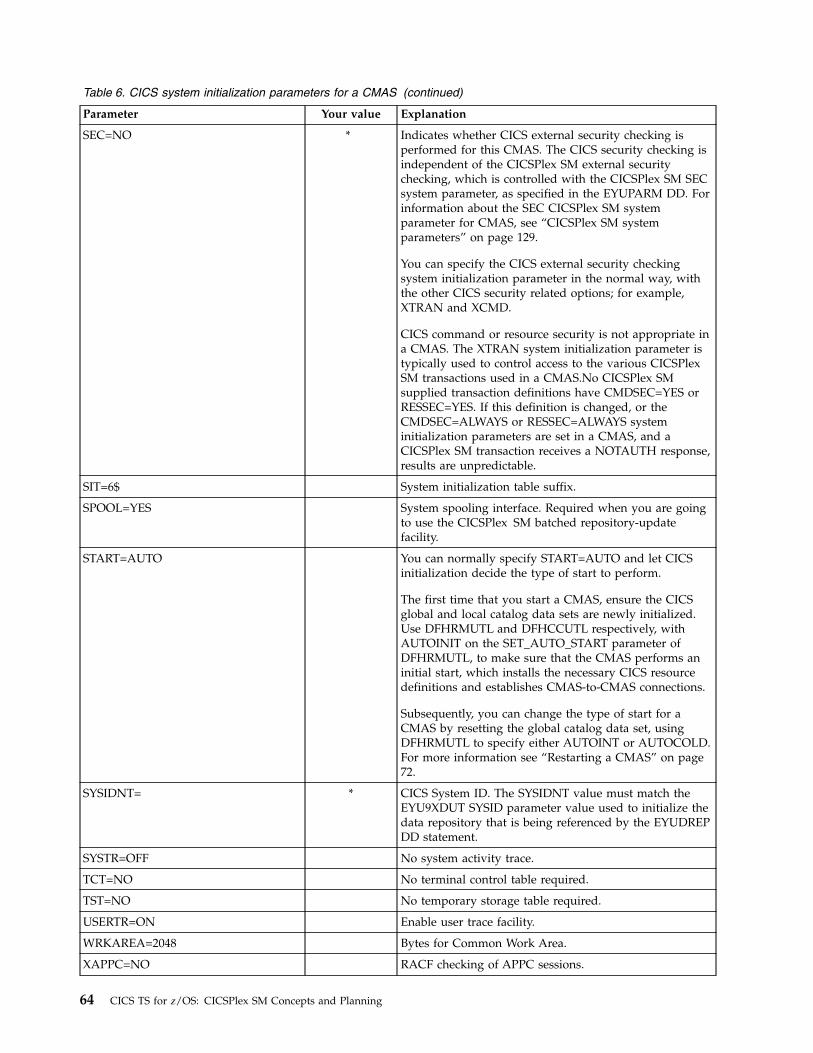
Table 6. CICS system initialization parameters for a CMAS (continued)
Parameter Your value Explanation
SEC=NO * Indicates whether CICS external security checking isperformed for this CMAS. The CICS security checking isindependent of the CICSPlex SM external securitychecking, which is controlled with the CICSPlex SM SECsystem parameter, as specified in the EYUPARM DD. Forinformation about the SEC CICSPlex SM systemparameter for CMAS, see “CICSPlex SM systemparameters” on page 129.
You can specify the CICS external security checkingsystem initialization parameter in the normal way, withthe other CICS security related options; for example,XTRAN and XCMD.
CICS command or resource security is not appropriate ina CMAS. The XTRAN system initialization parameter istypically used to control access to the various CICSPlexSM transactions used in a CMAS.No CICSPlex SMsupplied transaction definitions have CMDSEC=YES orRESSEC=YES. If this definition is changed, or theCMDSEC=ALWAYS or RESSEC=ALWAYS systeminitialization parameters are set in a CMAS, and aCICSPlex SM transaction receives a NOTAUTH response,results are unpredictable.
SIT=6$ System initialization table suffix.
SPOOL=YES System spooling interface. Required when you are goingto use the CICSPlex SM batched repository-updatefacility.
START=AUTO You can normally specify START=AUTO and let CICSinitialization decide the type of start to perform.
The first time that you start a CMAS, ensure the CICSglobal and local catalog data sets are newly initialized.Use DFHRMUTL and DFHCCUTL respectively, withAUTOINIT on the SET_AUTO_START parameter ofDFHRMUTL, to make sure that the CMAS performs aninitial start, which installs the necessary CICS resourcedefinitions and establishes CMAS-to-CMAS connections.
Subsequently, you can change the type of start for aCMAS by resetting the global catalog data set, usingDFHRMUTL to specify either AUTOINT or AUTOCOLD.For more information see “Restarting a CMAS” on page72.
SYSIDNT= * CICS System ID. The SYSIDNT value must match theEYU9XDUT SYSID parameter value used to initialize thedata repository that is being referenced by the EYUDREPDD statement.
SYSTR=OFF No system activity trace.
TCT=NO No terminal control table required.
TST=NO No temporary storage table required.
USERTR=ON Enable user trace facility.
WRKAREA=2048 Bytes for Common Work Area.
XAPPC=NO RACF checking of APPC sessions.
64 CICS TS for z/OS: CICSPlex SM Concepts and Planning

Table 6. CICS system initialization parameters for a CMAS (continued)
Parameter Your value Explanation
XCMD=NO For a CMAS you must specify NO for CICS commands.
XDB2=NO RACF checking of Db2 resources.
XDCT=NO RACF checking of transient data queues.
XFCT=NO For a CMAS you must specify NO for files.
XHFS=NO Security checking of Web client access to z/OS UNIXfiles. For a CMAS, you must specify XHFS=NO.
XJCT=NO RACF checking of journals.
XPSB=NO RACF checking of DL/I PSBs.
XRES=NO RACF checking of CICS document templates.
XRF=NO No XRF support. The extended recovery facility (XRF) isnot supported because of the way in which a CMAS usesMVS data spaces.
XTRAN=NO RACF checking of transaction-attach.
XTST=NO RACF checking of temporary storage queues.
Controlling tasks in a CMASMany operations in a CMAS are run by multiple asynchronous tasks, in particulara number of tasks that are performed between CMASs in a CMAS network.
Operations such as data repository synchronization, workload management statesharing and single system image can result in a number of interdependentasynchronous tasks being established or used to run the request. The number oftasks that can be used is based on other factors, such as the size of a CMASnetwork, how many MASs are being managed, how many CICSplexes are defined,how much API activity is performed, the scope of WUI/API/RTA requests and allthe major functions offered by CICSPlex SM.
Although a CMAS can self-regulate its tasking model and has tolerance of delayedrequests and responses through timeout mechanisms, maximum user tasks (MXT)does not apply to controlling an interdependent multitasked asynchronous taskingmodel. Set inappropriately, you might also experience WUI hanging for longdurations if one or more of the asynchronous tasks required to run the requestedfunction is delayed waiting for an MXT slot. Set MXT to avoid delays in taskattachment.
As task usage in a CMAS grows with the additional requirements that are placedon it, for example, increased use of the API, more CMASs, more MASs, and newfunction use, set the MXT value to a level that continues to avoid MXT delays.
Monitor any MXT value for its relationship against the task activity in each CMASat regular intervals. If the CMAS is starting to experience MXT delays, adjust theMXT value to avoid these delays.
To monitor the tasking activity in an individual CMAS, collect and study thestatistics generated by the CICS system that underlies the CMAS that it hosts. CICStransaction manager global statistics contain information on the effect the MXTvalue has on task attachment.
Chapter 2. Setting up CICSPlex SM 65

Creating and customizing CMAS data setsDFHISTAR allows you to create and customize your CMAS data sets, according tothe parameters you set when you submit the DFHISTAR job.
DFHISTAR postinstallation members for a CMAS
When you run DFHISTAR, with a SCOPE of POST or ALL, it creates the followingpostinstallation members for a CMAS in the XDFHINST library:v EYUCMSDS – creates and initializes all the data sets for a CMAS. EYUCMSDS
includes steps to delete the data sets so that you can rerun the job, if required.These deletions are expected to fail the first time you run the job. EYUCMSDScontains the following steps:1. DELDREP and DEFDREP delete and define a new CMAS data repository.2. DREPINIT is included if you do not specify the DFHISTAR OLDDREP
parameter. It initializes the new CMAS data repository using theEYU9XDUT utility. EYU9XDUT creates records on the data repository todefine the CMAS and, by default, a WUI CICSplex. A WUI CICSplex is notcreated if you specify the DFHISTAR WUI=NO option.
3. DREPCNVT is included if you specify the name of an existing datarepository using the DFHISTAR OLDDREP parameter. It copies all therecords from the existing repository to the new data repository, upgradingthem to a format suitable for the CICS TS for z/OS, Version 5.5 open betarelease.
4. DELREGDS deletes the CICS data sets.5. DEFTRACE defines the CICS auxiliary trace data sets, DFHAUXT and
DFHBUXT.6. DEFHTML defines the CICS DFHHTML data set.7. DEFDMPS defines the CICS transaction dump data sets, DFHDMPA and
DFHDMPB.8. DEFTSTD defines the CICS auxiliary temporary storage data set,
DFHTEMP.9. DEFINTD defines the CICS intrapartition transient data set, DFHINTRA.
10. DEFLCD defines the CICS local catalog, DFHLCD.11. INITLCD uses the DFHCCUTL utility to initialize the CICS local catalog.12. DEFGCD defines the CICS global catalog, DFHGCD.13. INITGCD uses the DFHRMUTL utility to initialize the CICS global catalog.14. DEFLRQ defines the CICS local request queue data set, DFHLRQ.15. JES3DELA and JES3DELB are included if you specify the DFHISTAR
JES=JES3 option. They delete and define the CICS DFHCSD data set.16. DELCSD deletes the CICS DFHCSD data set.17. DEFCSD defines the CICS DFHCSD data set.18. INITCSD uses the DFHCSDUP utility to initialize the DFHCSD data set.
v EYUCMSSP – CICS system initialization overrides for a CMAS.v EYUCMS0P – EYUPARM parameters for a CMAS.v EYUCMASP – starts a CMAS.v EYUCMASJ – JCL to start a CMAS. It runs EYUCMASP.
If you use the default values for the CICSPlex SM parameters, the EYUCMASPPROC statement is shown in the following code sample:
66 CICS TS for z/OS: CICSPlex SM Concepts and Planning

EYUCMASP PROC DSNCSD=’CICSTS55.CPSM.CMAS01.DFHCSD’,RGNHLQ=’CICSTS55.CPSM.CMAS01’,CICSHLQ=’CICSTS55.CICS’,CPSMHLQ=’CICSTS55.CPSM’,PRMLIB=’CICSTS55.XDFHINST’ACTHLQ=CICSTS55.CICSACTIVATE=SDFHLIC,CICSPRM=EYUCMSSP, CICS ParametersCPSMPRM=EYUCMS0P CPSM Parameters
Customizing postinstallation jobs using DFHISTAR
You can use DFHISTAR to generate copies of the CMAS postinstallation jobs for adifferent CMAS. DFHISTAR has a SELECT parameter that allows you to specify anew name for a copy of a postinstallation job. It has the format:SELECT jobname newname
jobnameIs the name of the job you want to regenerate.
newnameIs the name for the new copy.
You can specify more than one SELECT parameter to select multiple jobs to beregenerated in a single run of the DFHISTAR job. When you include a SELECTparameter in the DFHISTAR job, only those jobs specified by the SELECT aregenerated.
For a CMAS with the name CMAS02 and a CICS system identifier of CM02, youcan change your DFHISTAR parameters to specify the following values:CMASNAME CMAS02CMSSYSID CM02WUI YESWUIPLEX WUIPCM02WUINAME WUINCM02WUISYSID WU02SELECT EYUCMSDS CM02CMDS JCL to create the data sets for CMAS02SELECT EYUCMSSP CM02CMSP CICS SIT overrides for CMAS02SELECT EYUCMS0P CM02CM0P CICSPlex SM EYUPARM parameters for CMAS02
Using these parameters, CM02CMDS includes a step to initialize the CMAS datarepository with the definitions for a WUI called WUINCM02, in a CICSplex calledWUIPCM02. You can then start CMAS CMAS02, using the procedure EYUCMASP,to specify these parameters:START EYUCMASP, DSNCSD=’CICSTS55.CPSM.CMAS02.DFHCSD’,RGNHLQ=’CICSTS55.CPSM.CMAS02’, CICSHLQ=’CICSTS55.CICS’,CPSMHLQ=’CICSTS55.CPSM’, PRMLIB=’CICSTS55.XDFHINST’ACTHLQ=CICSTS55.CICSACTIVATE=SDFHLIC, CICSPRM=CM02CMSP, CPSMPRM=CM02CM0P
If you are using EYUCMASJ to start the WUI, edit it to specify these values:CICSPRM=CM02CMSP, CPSMPRM=CM02CM0P
Controlling CICS storage in a CMASA CICSPlex SM address space (CMAS) uses both MVS dataspace storage andstorage provided by the CICS system that hosts the CMAS. You must set theEDSALIM value and monitor the CICS storage use in a CMAS to ensure that theCMAS operates effectively.
Chapter 2. Setting up CICSPlex SM 67
A CMAS is a special application dedicated to the management and control ofmanaged application systems (MASs). A CMAS does not have a typical taskingmodel and uses MVS dataspace storage extensively. However, it also uses thestorage provided by the CICS system that hosts the CMAS.
With an interdependent multitasked asynchronous tasking model, a CMAS relieson shared storage to communicate between the tasks and the functions beingperformed. Also, depending on the requirements of a CMAS, it relies heavily onshared storage to buffer requests and responses to be transmitted usingCMAS-to-CMAS and CMAS-to-MAS links. The CICS system that hosts the CMASmanages this shared storage.
CICS storage use in a CMAS grows with the additional requirements that areplaced on it. For example, CICS storage use increases with increased use of theAPI, more CMASs, more MASs, increased CMAS-to-CMAS network traffic, andnew function uses.
The overall limit for the extended dynamic storage area (EDSA) is specified by theEDSALIM value. Set EDSALIM to a value that provides the CMAS with enoughstorage to operate unimpeded. In particular, sufficient storage for CMAS-to-CMASand CMAS-to-MAS network traffic is critical to WUI response times, because largeamounts of data might be awaiting shipment on any of the links on which aCMAS communicates.
Monitor any EDSALIM value for its effect on the storage use in each CMAS atregular intervals. If the CMAS experiences short on storage (SOS) conditions orstorage fragmentation, or there is a trend towards such conditions, considerincreasing the EDSALIM value to meet the storage requirements of the CMAS.Storage fragmentation below a largest free area of 64 KB can adversely affectthroughput and response times.
To monitor the storage use in an individual CMAS, collect and study the statisticsgenerated by the CMAS CICS system. CICS storage manager global statisticscontain information about the overall usage of CICS storage by the CMAS that ithosts.
START command for a CMASThe syntax of the command that you can use to start a CMAS is explained.START procname [,DSNCSD=dsn][,RGNHLQ=idx][,CICSHLQ=idx] [,CPSMHLQ=idx] [,PRMLIB=lib][,CICSPRM=mem][,CPSMPRM=mem]
procnameIs the 1- to 8-character name of the procedure. EYUCMASP is the name ofthe sample procedure. It is supplied, uncustomized, in the TDFHINSTlibrary and, customized by DFHISTAR, in the XDFHINST library.
DSNCSD=dsnSpecifies the name of the data set that contains the CSD file for the CMAS.
RGNHLQ=idxSpecifies the high-level qualifier that is used with the DFHxxxx data setsthat are unique to this CMAS.
CICSHLQ=idxSpecifies the high-level qualifier that is used with the SDFHAUTH andSDFHLOAD libraries.
68 CICS TS for z/OS: CICSPlex SM Concepts and Planning

CPSMHLQ=idxSpecifies the high-level qualifier that is used with the SEYUAUTH andSEYULOAD libraries.
PRMLIB=idxSpecifies the name of the library containing the members identified byCICSPRM and CPSMPRM.
CICSPRM=memIdentifies the member that contains the CICS system initializationparameters. The EYUCMSSP sample is supplied, uncustomized, in theTDFHINST library and, customized by DFHISTAR, in the XDFHINSTlibrary.
CPSMPRM=memIdentifies the member that contains the CICSPlex SM system parameters.The EYUCMS0P sample is supplied, uncustomized, in the TDFHINSTlibrary and, customized by DFHISTAR, in the XDFHINST library.
CMAS journalingA CMAS can produce CICS journal records to track a variety of activities in theCICSplex. These journal records provide an audit trail that can aid in the recoveryof data or the reconstruction of events that affected the CICSplex.
A journal record can be written under these circumstances:v A definition in the data repository is added, removed, or updated.v An operations action is issued against a MAS.v A real-time analysis event is generated.
The journal records are stored in a 32 KB buffer and are flushed to thecorresponding log streams when the buffer becomes full or when a normalshutdown of the CICS region is initiated.
To force the buffer to be flushed to a log stream when the CICS region is stillactive, you can specify the WAIT option on the WRITE JOURNALNAMEcommand using EXEC CICS or the CECI transaction.
To request one or more of the record types, specify the appropriate CICSPlex SMsystem parameters in the startup JCL of a CMAS:
JRNLDEFCH(YES)For data repository definition changes
JRNLOPACT(YES)For operations actions
JRNLRTAEV(YES)For real-time analysis events
For more information on these parameters, see “CICSPlex SM system parameters”on page 129.
If you do not want to use the default log stream name of EYUJRNL, define aJOURNALMODEL resource in the CSD that has the required log stream name.
Chapter 2. Setting up CICSPlex SM 69

v To make the JOURNALMODEL resource definition available during CMASinitialization, include the JOURNALMODEL resource definition in a CSD grouplist. Include this group list in your CMAS startup using the system initializationGRPLIST parameter.
v To add the JOURNALMODEL resource to the CSD, either edit and run the JCLcontained in sample member CICSTS55.CPSM.SEYUSAMP(EYUJRNE$) to runbatch utility DFHCSDUP or use the CICS CEDA transaction.
v You must also update the CICS system initialization parameters used to start theCMAS by setting the GRPLIST parameter to reference the new group list.
The journal records produced by a CMAS contain data mapped by a DSECT calledEYUBCPJR. Each record consists of a standard prefix and a variable data area. Thecontents of the data area are specific to the type of journal record being written.
Figure 15 on page 71 shows the format of EYUBCPJR.
*---------------------------------------------------------------------** EYUBCPJR DSECT Prefix **---------------------------------------------------------------------*EYUBCPJR DSECTEYUBCPJR DS 0D
CPJR_PREFIX DS 0D Prefix of recordCPJR_CMASNAME DS CL8 CMAS Name which produced recordCPJR_CONTEXT DS CL8 Plex NameCPJR_SCOPE DS CL8 Scope NameCPJR_USER DS CL8 User NameCPJR_STCK DS D Store clockCPJR_VERSION DS H Current record versionCPJR_VER_ZERO EQU 0000 Version 0CPJR_VER_ONE EQU 0001 Version 1CPJR_VER_CURR EQU CPJR_VER_ONE Current VersionCPJR_TYPE DS H Record typeCPJR_TYPE_DEFCH EQU 0001 Definition Add/Change/DeleteCPJR_TYPE_RTAEV EQU 0002 Rta EventCPJR_TYPE_OPACT EQU 0003 Operation actionCPJR_LENGTH DS F Length of entire record plus x
prefix areaDS FL8 Available for use
CPJR_LEN EQU *-CPJR_PREFIX Length of Prefix areaCPJR_DATA_AREA DS 0H Data area
*---------------------------------------------------------------------** Data record for RTA Events **---------------------------------------------------------------------*
CPJR_RTA_DATA DS 0HCPJR_RTA_TYPE DS X Record typeCPJR_RTATYPE_CRT EQU 0001 Event CreatedCPJR_RTATYPE_REM EQU 0002 Event RemovedCPJR_RTATYPE_UPD EQU 0003 Event UpdatedCPJR_RTATYPE_RES EQU 0004 Event ResolvedCPJR_RTA_GTYPE DS X Generated by typeCPJR_RTAGTYPE_SAM EQU 0001 Event produced by SamCPJR_RTAGTYPE_APM EQU 0002 Event produced by ApmCPJR_RTAGTYPE_MRM EQU 0003 Event produced by MrmCPJR_RTA_EVENT DS CL8 Event NameCPJR_RTA_MSGSTRT DS CL30 External Entry MessageCPJR_RTA_MSGEND DS CL30 External Exit MessageCPJR_RTA_EVENTXT DS CL30 Event TextCPJR_RTA_SEVERITY DS CL3 Severity LevelCPJR_RTA_DATA_L EQU *-CPJR_RTA_DATA Length of the record
70 CICS TS for z/OS: CICSPlex SM Concepts and Planning
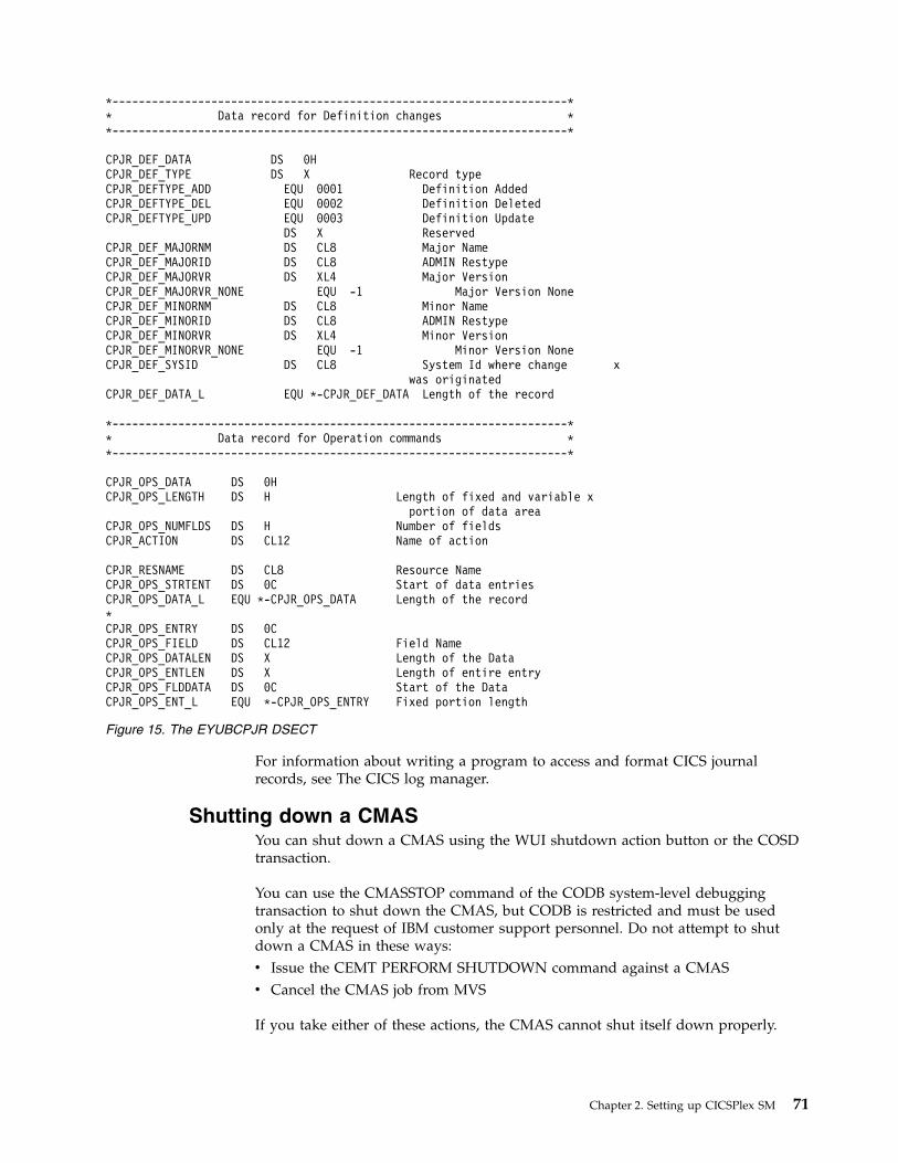
For information about writing a program to access and format CICS journalrecords, see The CICS log manager.
Shutting down a CMASYou can shut down a CMAS using the WUI shutdown action button or the COSDtransaction.
You can use the CMASSTOP command of the CODB system-level debuggingtransaction to shut down the CMAS, but CODB is restricted and must be usedonly at the request of IBM customer support personnel. Do not attempt to shutdown a CMAS in these ways:v Issue the CEMT PERFORM SHUTDOWN command against a CMASv Cancel the CMAS job from MVS
If you take either of these actions, the CMAS cannot shut itself down properly.
*---------------------------------------------------------------------** Data record for Definition changes **---------------------------------------------------------------------*
CPJR_DEF_DATA DS 0HCPJR_DEF_TYPE DS X Record typeCPJR_DEFTYPE_ADD EQU 0001 Definition AddedCPJR_DEFTYPE_DEL EQU 0002 Definition DeletedCPJR_DEFTYPE_UPD EQU 0003 Definition Update
DS X ReservedCPJR_DEF_MAJORNM DS CL8 Major NameCPJR_DEF_MAJORID DS CL8 ADMIN RestypeCPJR_DEF_MAJORVR DS XL4 Major VersionCPJR_DEF_MAJORVR_NONE EQU -1 Major Version NoneCPJR_DEF_MINORNM DS CL8 Minor NameCPJR_DEF_MINORID DS CL8 ADMIN RestypeCPJR_DEF_MINORVR DS XL4 Minor VersionCPJR_DEF_MINORVR_NONE EQU -1 Minor Version NoneCPJR_DEF_SYSID DS CL8 System Id where change x
was originatedCPJR_DEF_DATA_L EQU *-CPJR_DEF_DATA Length of the record
*---------------------------------------------------------------------** Data record for Operation commands **---------------------------------------------------------------------*
CPJR_OPS_DATA DS 0HCPJR_OPS_LENGTH DS H Length of fixed and variable x
portion of data areaCPJR_OPS_NUMFLDS DS H Number of fieldsCPJR_ACTION DS CL12 Name of action
CPJR_RESNAME DS CL8 Resource NameCPJR_OPS_STRTENT DS 0C Start of data entriesCPJR_OPS_DATA_L EQU *-CPJR_OPS_DATA Length of the record*CPJR_OPS_ENTRY DS 0CCPJR_OPS_FIELD DS CL12 Field NameCPJR_OPS_DATALEN DS X Length of the DataCPJR_OPS_ENTLEN DS X Length of entire entryCPJR_OPS_FLDDATA DS 0C Start of the DataCPJR_OPS_ENT_L EQU *-CPJR_OPS_ENTRY Fixed portion length
Figure 15. The EYUBCPJR DSECT
Chapter 2. Setting up CICSPlex SM 71

If you shut down more than one CMAS at the same time, you might receivemessage EYUCP0205S. In this situation, the message does not indicate a problem,and CICSPlex SM does not produce a diagnostic SVC dump as it normally wouldwhen this message is issued. You can avoid the message by staggering your CMASshutdowns.
Using the Shutdown button1.
v From the main menu, click CICSPlex SM operations views > CMASsknown to local CMAS to open the CMASs known to local CMAS tabularview.
v Select the record check box beside the CMAS and click Shutdown.... TheShutdown confirmation view is displayed.
v Click Yes to confirm. The CMASs known to local CMAS tabular view isdisplayed again, showing a status of INACTIVE for that CMAS.
2.
v From the main menu, click CICSPlex SM operations views > MASs knownto CICSplex to display the MASs known to CICSplex tabular view.
v Click the CMAS name to display the CMAS detail view.v Click Shutdown.... The Shutdown confirmation view is displayed.v Click Yes to confirm. The MASs known to CICSplex tabular view is
displayed again.
Using the COSD transaction
You can issue the transaction ID, COSD, from any terminal, including an MVSconsole:COSD
Restarting a CMASYou can restart a CMAS automatically, by performing a cold restart, or by doing anemergency restart.
Automatic restart
You can perform an automatic restart for a CMAS that you stopped normallyeither with the COSD transaction, or the WUI SHUTDOWN button. Automatedrestart is the preferred way of restarting a CMAS because it delegates the decisionon whether to do an initial, cold, warm or emergency restart to CICS. CICS makesthe decision by inspecting two records in the global catalog: the recovery managercontrol record, and the recovery manager autostart override record.
To do an automatic restart:v Specify the AUTO option on the START system initialization parameter.
Cold restart
A manual cold restart is necessary if you have modified any of the CICS resourcedefinitions that are used by the CMAS. You must also perform a manual coldrestart if you have added or removed any of the CMAS-to-CMAS (CMTCMDEF)connection definitions.
To do a cold restart:
72 CICS TS for z/OS: CICSPlex SM Concepts and Planning

v Specify the COLD option on the START system initialization parameter.
Emergency restart
A manual emergency restart is necessary if a CMAS ends abnormally (in any wayother than from the COSD transaction, or from using the WUI SHUTDOWNbutton). During an emergency restart, CICS performs essential backout processing.If the CMAS is registered with the MVS automatic restart manager (ARM), anemergency restart occurs automatically. If the CMAS is not registered with ARMyou must perform the emergency restart yourself.
To do an emergency restart:v Specify the AUTO option on the START system initialization parameter.
A CMAS initializes and functions properly after an emergency restart, providedthat you have made no changes to the CICS resource definitions or CICSPlex SMconnection definitions.
If you have made changes since the last run of the CMAS (that is, the run thatended abnormally), the CMAS might not function properly. In this situation, youmust shut down the CMAS using either the COSD transaction, or theWUI SHUTDOWN button and restart the CMAS, specifying the START=COLDoption. For information about shutting down a CMAS, see “Shutting down aCMAS” on page 71.
Setting up a CICS managed application system (MAS)There are a number of steps you must perform so that a CICS system can beknown as a managed application system (MAS) to CICSPlex SM.
Note: If a MAS specifies a CMASSYSID and the CMAS is active but does notmanage the CICSplex, the MAS waits until the specified CMAS is managing theCICSplex before it joins the CICSplex. This behavior is the same as whenCMASSYSID is not specified.
Before you set up a MASCheck your initialization values, changes between releases and maintenance youmight need to apply to your system.
Check the considerations for setting up a MAS, described in “Designing yourCICSPlex SM environment” on page 21.
Check the IEASYSxx member of SYS1.PARMLIB that you use for MVS initializationand note the initialization values that are referenced during installation. For detailsabout initialization values, see Noting IEASYSxx values for CICSPlex SM.
If you are converting your CICSPlex SM system or systems from a previous releaseto CICSPlex SM for CICS Transaction Server for z/OS, Version 5 Release 5 openbeta , read the upgrading information for your level of CICSPlex SM.
Using CICS global user exits and user-replaceable modulesYou can use CICS global user exits and the user replaceable module, DTRPROG tomonitor a MAS.
Chapter 2. Setting up CICSPlex SM 73

The way these exits are used by CICSPlex SM conforms to the standard describedin Customizing with user-replaceable programs in Developing system programs.CICSPlex SM uses these exits only to acquire information; the applicationenvironment is not altered.
The XMNOUT and XSTOUT exits are used when monitoring services are enabledfor a CICSPlex SM managed application system (MAS):v The XMNOUT exit obtains task and CICS monitoring data. XMNOUT is used
only with a local MAS.v The XSTOUT exit obtains statistical data before the data is reset by CICS.
These exits obtain monitoring and statistics information and always return a“continue processing” return code. They are not available when a shutdownrequest for the MAS is received.
The XMEOUT, XDUREQ, XDUREQC, XRSINDI, XSNOFF, and XDUOUT exits areused when topology requests are enabled for a local MAS:v The XMEOUT exit detects short-on-storage events.v The XDUREQ exit detects system dump and transaction dump events.v The XDUREQC exit detects the completion of dump action.v The XRSINDI exit detects topology resource changes.v The XSNOFF exit detects user sign-off events.v The XDUOUT exit detects transaction dump events.
CICSPlex SM uses the dynamic routing program user replaceable module(DTRPROG) as part of workload balancing.
Controlling the use of modules from the LPAYou can control whether CICS uses modules from the LPA, either by specifying theLPA and PRVMOD CICS system initialization parameters , or by including orexcluding the SYS1.CICSTS55.CPSM.SEYULPA library (defined to MVS as an LPAlibrary) in the STEPLIB or DFHRPL concatenations.1. A module that is link-edited with the RMODE(ANY) attribute is loaded into
the ELPA.2. It is important to remember that the LPA-resident version of a module that is
usually loaded from STEPLIB is not used from the LPA if it is left in theSTEPLIB DD concatenation of libraries. If a module is found in the STEPLIBconcatenation, it is loaded into the private area of the address space, and theLPA version ignored. You can avoid this situation by moving the LPA-eligiblemodules into an LPA library, as described in Installing CICSPlex SM modulesinto the LPA.
For further information about controlling the use of LPA-eligible modules, seeInstalling CICSPlex SM modules in the MVS link pack area, taking particular noteof information concerning:v The module-not-found warning message DFHLD0109Iv CICS system initialization parameters related to LPA modules
Preparing to start a z/OS MASBefore you start a MAS, create your data sets, change startup JCL, activate externalconnections, review system initialization parameters, and prepare your logs.
74 CICS TS for z/OS: CICSPlex SM Concepts and Planning

Start any MASs (that is, the CICS systems the CMAS is to manage) after theCMAS, because a CICS system is unknown to CICSPlex SM until the CMAS withwhich the CICS system is associated is started.
Note: If a MAS specifies a CMASSYSID and the CMAS is active but does notmanage the CICSplex, the MAS waits until the specified CMAS is managing theCICSplex before it joins the CICSplex. This behavior is the same as whenCMASSYSID is not specified.
Creating and customizing MAS data setsUse DFHISTAR to create and customize your managed CICS system (MAS) datasets, according to the parameters that you set when you submit the DFHISTAR job.
DFHISTAR postinstallation members for a MAS
When you run DFHISTAR, with a SCOPE of POST or ALL, it creates the followingpostinstallation members for a managed CICS system (MAS) in the XDFHINSTlibrary:v EYUCSYDS – creates and starts all the data sets for a MAS. EYUCSYDS includes
steps to delete the data sets so that you can rerun the job, if required. Thesedeletions are expected to fail the first time that you run the job. EYUCSYDScontains the following steps:1. DELHIST and DEFHIST delete and define CICSPlex SM history data sets
EYUHISTA and EYUHISTB.2. HISTINIT uses the EYU9XHID utility to start the history data sets.3. JES3DELA and JES3DEFA are included if you specify the DFHISTAR
JES=JES3 option. They delete and define the CICS local catalog, the globalcatalog, and the local request queue.
4. DELREGDS deletes the CICS data sets.5. DEFTRACE defines the CICS auxiliary trace data sets, DFHAUXT and
DFHBUXT.6. DEFHTML defines the CICS DFHHTML data set.7. DEFDMPS defines the CICS transaction dump data sets, DFHDMPA and
DFHDMPB.8. DEFTSTD defines the CICS auxiliary temporary storage data set,
DFHTEMP.9. DEFINTD defines the CICS intrapartition transient data set, DFHINTRA.
10. DEFLCD defines the CICS local catalog, DFHLCD.11. INITLCD uses the DFHCCUTL utility to start the CICS local catalog.12. DEFGCD defines the CICS global catalog, DFHGCD.13. INITGCD uses the DFHRMUTL utility to start the CICS global catalog.14. DEFLRQ defines the CICS local request queue data set, DFHLRQ.15. JES3DEFA and JES3DELB are included if you specify the DFHISTAR
JES=JES3 option. They delete and define the CICS DFHCSD data set.16. DELCSD deletes the CICS DFHCSD data set.17. DEFCSD defines the CICS DFHCSD data set.18. INITCSD uses the DFHCSDUP utility to start the DFHCSD data set.
v EYUJHIST creates a pair of CICSPlex SM history data sets. EYUCSYDS includessteps to create two history data sets, EYUHISTA and EYUHISTB. You can useEYUJHIST if you want to add more history data sets (up to a maximum of 26).It contains the following steps:
Chapter 2. Setting up CICSPlex SM 75

– DELHIST and DEFHIST delete and define a pair of CICSPlex SM history datasets.
– HISTINIT uses the EYU9XHID utility to start the history data sets.v EYULMSSP provides CICS system initialization overrides for a managed CICS
system.v EYULMS0P provides CICSPlex SM EYUPARM parameters for a managed CICS
system.v EYUCSYSP starts a managed CICS system.v EYUCSYSJ starts a managed CICS system. It runs EYUCSYSP.
If you use the default values for the CICSPlex SM parameters, the EYUCSYSPPROC statement is shown in the following code sample:
EYUCSYSP PROC DSNCSD=’CICSTS55.CPSM.CSYS01.DFHCSD’,RGNHLQ=’CICSTS55.CPSM.CSYS01’,CICSHLQ=’CICSTS55.CICS’,CPSMHLQ=’CICSTS55.CPSM’,PRMLIB=’CICSTS55.XDFHINST’,CICSPRM=EYULMSSP, CICS ParametersCPSMPRM=EYULMS0P CPSM Parameters
Customizing postinstallation jobs using DFHISTAR
You can use DFHISTAR to generate copies of the managed CICS systempostinstallation jobs for a different CICS region. Use the DFHISTAR SELECTparameter to specify a new name for a copy of a postinstallation job. It has thisformat:SELECT jobname newname
jobnameIs the name of the job that you want to regenerate
newnameIs the name for the new copy.
You can specify more than one SELECT parameter to select multiple jobs to beregenerated in a single run of the DFHISTAR job. When you include a SELECTparameter in the DFHISTAR job, only those jobs specified by the SELECT aregenerated.
For a MAS with the name CSYS02 and a CICS system identifier of CS02, you canchange your DFHISTAR parameters to specify these options:
CMASNAME name of the CMAS to which this managed system connectsCMSSYSID CICS system identifier of the CMAS to which this managed system connectsCSYSPLEX name of the CICSplex to which this managed system is to be associatedCSYSNAME CSYS02CSYSYSID CS02SELECT EYUCSYDS CS02CSDS JCL to create the data sets for CSYS02SELECT EYULMSSP CS02CSSP CICS system initialization overrides for CSYS02SELECT EYULMS0P CS02CS0P CICSPlex SM EYUPARM parameters for CSYS02
You can then start the managed CICS system, CSYS02, using the procedureEYUCSYSP:START EYUCSYSP, DSNCSD=’CICSTS55.CPSM.CSYS02.DFHCSD’,RGNHLQ=’CICSTS55.CPSM.CSYS02’, CICSHLQ=’CICSTS55.CICS’,CPSMHLQ=’CICSTS55.CPSM’, PRMLIB=’CICSTS55.XDFHINST’CICSPRM=CM02CSSP, CPSMPRM=CM02CS0P
If you are using EYUCSYSJ to start the WUI, edit it to specify these options:CICSPRM=CS02CSSP, CPSMPRM=CS02CS0P
76 CICS TS for z/OS: CICSPlex SM Concepts and Planning

Changing startup JCL before starting a MASChange the startup JCL for the system by modifying your DD statements toinclude the CICSPlex SM data sets and verifying that the appropriate CICS systeminitialization parameters are included.
The DD statements that you must modify are shown in Figure 16.
...//STEPLIB DD DSN=CICSTS55.CPSM.SEYUAUTH,DISP=SHR//DFHRPL DD DSN=CICSTS55.CPSM.SEYULOAD,DISP=SHR//EYUPARM DD DSN=(Any PO or PS data set with LRECL=80)//EYUHISTA DD DSN=(Optional 1st history data set)//EYUHISTB DD DSN=(Optional 2nd history data set)//EYUHISTn DD DSN=(Optional nth history data set)
...
When you change these DD statements in the startup JCL for a CICS system, codethese statements as follows:
STEPLIB DD statement Includes the CICSTS55.CPSM.SEYUAUTH authorized load library.
DFHRPL DD statement Includes the CICSTS55.CPSM.SEYULOAD load library.
EYUPARM DD statement Identifies the library containing the CICSPlex SM parameters.v Member EYULMS0P, in the CICSTS55.CPSM.SEYUPARM data set,
contains sample system parameters for a local MAS; you must edit thismember. See “CICSPlex SM system parameters” on page 129 for adetailed description of each parameter. EYULMS0P is supplied,uncustomized, in TDFHINST and customized in XDFHINST.
v If you want to use Business Application Services to install CICSresources in a MAS, you must specify the CICSPlex SM systemparameter MASPLTWAIT(YES) for that system. This parameter suspendsCICS PLT processing until all CICS resources are installed and theCICSPlex SM MAS is fully initialized.
v If you want to include a MAS in a platform, you must also specify theCICSPlex SM system parameter MASPLTWAIT(YES) for that system.This parameter is required to automatically install CICS resources for anapplication or platform when the CICS region is initialized.
EYUHISTx DD statement Identifies the history data sets for the MAS. Each MAS must have its ownset of CICSPlex SM history data sets. You allocate the data sets to the MASregion by means of DD cards in the JCL with DD names of the formEYUHISTx, where x is a character suffix taking values A through Z.Dynamic allocation is not supported. Allocate the data sets with adisposition of OLD. Use the suffix letters in ascending sequence and omitno letters. For example, if four history data sets are required, use DDnames EYUHISTA, EYUHISTB, EYUHISTC, and EYUHISTD. See“Preparing the MAS for history recording” on page 81.
Activating Db2 and IBM MQ connections during CICS startupIf you are using Db2 or IBM MQ with CICS, you must make special arrangementsto define and activate your connections.
Figure 16. z/OS MAS-specific JCL requirements
Chapter 2. Setting up CICSPlex SM 77

Db2 connections
When you use CICS Transaction Server for z/OS, Version 5 Release 5 open betaCICS systems with the CICS Db2 attachment facility, you make specialarrangements when you use BAS to install a Db2 connection defined toCICSPlex SM. When BAS is used to define and then install a Db2 connection, theconnection starts in NOTCONNECTED status. You can use the WUI to cause theconnection to the Db2 subsystem to be activated in the following way:1. From the WUI Main menu, click CICS operations views > DB2, DBCTL and
IBM MQ operations views > Connections (under DB2 operations views).2. Select the objects to change.3. Click the Connect button.
In a test environment, you might be able to wait for the MAS to start and theninstall the BAS definition. Then issue a CONNECT command against the resultingDB2CONN.
However, in a production system, you might want the connection to beautomatically activated when the MAS starts up, as part of the PLT processingsequence, so that the Db2 subsystem can be accessed immediately by programsand users. Specifying the CICS system initialization parameter DB2CONN=YESdoes not by itself activate the connection, because at the time the systeminitialization parameters are processed, CICSPlex SM has not yet installed anyDB2CDEF objects.
Activate a Db2 connection during CICS startup in the following way:1. Ensure that you can install an appropriate DB2CDEF resource definition for
CICSPlex SM, and that the definition is set up for automatic installation.2. Specify the MASPLTWAIT(YES) CICSPlex SM parameter, which causes the
DB2CDEF resource definition (as well as all other BAS resource definitions) tobe installed during PLT processing.
3. Arrange for the appropriate Db2 connect program to be started after the MASstartup program (EYU9NXLM for a local MAS).
IBM MQ connections
You cannot use BAS to define and install a IBM MQ for z/OS connection beforethe CICSPlex SM environment has been initialized.
z/OS MAS-related CICS system initialization parametersVerify that the sequential data set or partitioned data set member identified by theCICS SYSIN statement includes the appropriate CICS system initializationparameters.
Table 7 on page 79 describes the parameters in more detail.
Review all of the listed parameters for each MAS, to ensure that the valuesspecified are appropriate. When you specify YES for a specific resource type(XCMD, XFCT, XPCT, or XPPT), a CICSPlex SM security profile must exist for thatresource type. See the CICSPlex SM security for information about creating securityprofiles.
Note: To get all data available for the TASK and MLOCTRAN views, MCT musthave a value specified, CICS monitoring for performance classes must be activated,
78 CICS TS for z/OS: CICSPlex SM Concepts and Planning

and you must be collecting performance class data. See the note for MCT,MONITOR, MN, and MNPER parameters in the following table .
Table 7. CICS system initialization parameters for a z/OS MAS
Parameter Explanation
APPLID= z/OS Communications Server application ID for this CICS system. Usedas MAS name when NAME(value) is not specified as a CICSPlex SMsystem parameter.
AIEXIT=DFHZATDX z/OS Communications Server terminal autoinstall program.
AUTORESETTIME=YES Time-of-day synchronization.
AUXTR=ON Auxiliary trace - exception records.
AUXTRSW=NEXT No continuous auxiliary trace switching.
CPSMCONN=LMAS Initialize the region as a local MAS.
DFLTUSER=userid Specify the user identifier that is to be used for security checking when auser is not defined to the ESM.
DSALIM=5M Limit of DSA storage in 24-bit (below-the-line) storage. Set this value to atleast 5 MB.
EDSALIM=800M Limit of EDSA storage in 31-bit (above-the-line) storage.
DSRTPGM=EYU9XLOP Distributed START routing program.
DTRPGM=EYU9XLOP Dynamic routing program.
DUMPDS=A Transaction dump data set.
DUMPSW=NEXT Switch to next transaction dump data set.
FCT=NO A file control table is not used.
GMTEXT='CICSPlex System Manager -CICS Transaction Server for z/OS'
Default logon message.
GRPLIST=DFHLIST Add group lists for your application resource definitions. See CICSresource definitions for CICSPlex SM for additional information.
ICV=100 Region exit interval.
ICVR=5000 Runaway task interval.
ICVTSD=0 Terminal scan delay interval.
INTTR=ON Activate main storage trace.
IRCSTRT=YES IRC started at system initialization.
ISC=YES Code YES to include the CICS programs that are required for interregionand intersystem communications.
MCT= Monitoring control table. If you have CICS performance class monitoringactive, you must specify a value for this parameter. You can use 2$ (thedefault) or an existing table. See note.
MN=ON Activates CICS Monitor. See note.
MNFREQ=001500 Writes performance class data every 15 minutes.
MNPER=ON Tells CICS to monitor performance classes. See note.
Note for MCT, MONITOR, MN, and MNPER parameters: To obtain all data available for the TASK andMLOCTRAN views, MCT must have a value specified, CICS monitoring for performance classes must be activated,and you must be collecting performance class data.
If you do not want this data written to an SMF data set, you can suppress the monitor records. See the descriptionof the SUPPRESSCMF parameter in “CICSPlex SM system parameters” on page 129.
Chapter 2. Setting up CICSPlex SM 79

Table 7. CICS system initialization parameters for a z/OS MAS (continued)
Parameter Explanation
MXT=500 Maximum tasks. Increase by 20 from your normal value for the CICSregion to accommodate the CICSPlex SM MAS tasks. CICSPlex SM rarelyuses all 20 of these additional tasks. If you are using the MXT value aloneto control application transactions, increasing this value can allow moreapplication transactions to run concurrently. To prevent this situation fromoccurring, you can define a transaction class for the application. Then, seta class maximum task (CMXT) value that limits the number of concurrenttransactions.
SEC= {YES|NO} Indicate whether external security checking is to be performed for thisCICS system:
YES When READ access is granted:
v READ is permitted
v UPDATE is refused.
When UPDATE access is granted:
v READ is permitted
v UPDATE is permitted.
NO Security checking is not performed.
1. For CICS security, the value specified with SEC= for a CMAS overridesthe value specified with SEC= for a MAS.
2. For CICSPlex SM security to be active, set SEC=YES for a MAS. TheCMAS to which it connects must have the CICSPlex SM systemparameter SEC(YES). When CICSPlex SM security is not activated inthe CMAS, the connection between the CMAS and the MAS cannot beestablished. If the connection is attempted, message EYUCR0007E isissued to the console, the CMAS joblog, and the EYULOG.
For more information about the SEC parameter for the CMAS, see“CICSPlex SM system parameters” on page 129.
SECPRFX={YES | NO |prefix} Specify whether the user ID is used as the prefix that is added to thebeginning of all resource names to distinguish this CICS system fromother CICS systems.
SIT=6$ System initialization table suffix.
SPOOL=YES System spooling interface.
START=AUTO Cold start overriding other options.
SYSIDNT= Indicate the ID of the CICS system. This name must be unique in aCICSplex.
SYSTR=OFF Auxiliary trace - no system activity.
TCT=NO A terminal control table is not used.
TS=(COLD,3) Cold start temporary storage.
TST=NO A temporary storage table is not used.
USERTR=ON Auxiliary trace - enable user trace.
XAPPC=NO RACF checking of APPC sessions.
TCPIP=YES Activate CICS TCPIP services.
XCMD= {YES|name|NO} Indicate whether EXEC CICS system commands are to be included insecurity checking.
XDB2= {No|name} Indicate whether Db2 resources are to be included in security checking.
XDCT=NO RACF checking of transient data queues.
80 CICS TS for z/OS: CICSPlex SM Concepts and Planning

Table 7. CICS system initialization parameters for a z/OS MAS (continued)
Parameter Explanation
XFCT= {YES|name|NO} Indicate whether files are to be included in security checking.
XHFS=NO Security checking of Web client access to z/OS UNIX files.
XPCT= NO RACF checking of EXEC-started transactions.
XPPT= {YES|name|NO} Indicate whether programs are to be included in security checking.
XRES=NO Security checking of access to CICS resources subject to XRES securitychecks. For a list of resources subject to XRES security checks, see Securityusing the XRES resource security parameter.
XRF=NO XRF support is not generated.
XPSB=NO RACF checking of DL/I PSBs.
XTRAN=NO RACF checking of transaction-attach.
XTST=NO RACF checking of temporary storage queues.
XUSER={YES|NO} Indicates whether CICS is to perform surrogate user checks. If you specifyYES, you must define the CICS region user ID as a surrogate of the userID that starts a MAS using the COLM or CORM transaction.
Preparing the MAS for history recordingWith CICSPlex SM, you can save and view data for completed tasks; that is,historical task data.
When an active task completes, its data is stored in a historical data store. The datastore is made up of a number of VSAM KSDS data sets. You need a minimum oftwo data sets and a maximum of twenty six data sets.
Each MAS must have its own set of CICSPlex SM history data sets. Allocate thedata sets to the MAS region by means of DD cards in the JCL with DD names ofthe form EYUHISTx, where x is a character suffix taking values A through Z.Dynamic allocation is not supported. Allocate the data sets with a disposition ofOLD. Use the suffix letters in ascending sequence with no letters omitted. Forexample, if four history data sets are required, use DD names EYUHISTA,EYUHISTB, EYUHISTC, and EYUHISTD.
Define the CICSPlex SM history data sets with the REUSE keyword. Task historyrecording uses the least recently used data set, or, when starting for the first time,EYUHISTA. When EYUHISTA becomes full, it switches to use EYUHISTB and soon in sequence. Each full data set remains open with its data available until thehistory recorder has filled all data sets and starts reusing the data sets. At thistime, EYUHISTA is set closed, emptied, reopened, and reused first, followed byEYUHISTB and so on in sequence. If a data set is reused, its previous contents aredestroyed.
Until the history recorder has to empty a data set to reuse it, the historical taskdata is available for use. The data is maintained across CMAS and MAS restarts.You do not have to define the history data sets as recoverable because unit-of-workrecoverability is not required. However, the CICSPlex SM history recorder doesrequire files to be defined as nonrecoverable to avoid unnecessary logging in theMAS region.
In addition, do not define the history data sets to use VSAM compression. TheCICSPlex SM history function initializes the data sets to calculate how manyrecords fit in the data set, so that it can safely use sequential writes to the data set,
Chapter 2. Setting up CICSPlex SM 81

thereby reducing I/O use. Use of VSAM compression spoils that calculation andcauses data to be lost when the data set becomes full and a data set switch isrequired.
CICSPlex SM provides a tuning aid, the HISTRECSMSG EYUPARM parameter, todetermine the optimum size for history data sets. HISTRECSMSG can activate theperiodic output of messages detailing how many thousand records have beenwritten to the data set. Each completed task has one record. Because CICS filecontrol supports extended format KSDS data sets, you can define large history datasets over 4 GB in size. However, when considering the use of very large data sets,take into account that when the CICSPlex SM history recorder reuses a data set byemptying it, a large amount of data is lost and not available for subsequentqueries. An alternative approach to a small number of very large data sets is tospread the data over more data sets. For example, by having 25 data sets, each onecapable of holding one hour's worth of completed task data, at least one day'sworth of data can always be maintained. When the oldest data set is reused, onlyone hour's worth of data is lost.
CICSPlex SM provides a sample job, EYUJHIST, for defining and initializing twohistory data sets. It is supplied, non-customized, in TDFHINST, and customized byDFHISTAR in XDFHINST.
Stopping and restarting management of a CICS systemYou can stop and restart management of a MAS in an active CICS system. You canalso check that MAS shutdown processing is properly installed.
Stopping management of a CICS system
You can stop the MAS agent code in an active CICS system in two ways:v From the WUI Main menu, click CICSPlex SM operations views > MASs
known to CICSplex > , select the CICS systems and click Stop, orv Run transaction COSH in the MAS. You start COSH at a 3270 terminal, at a
console, or using ATI.
When you stop the MAS agent, CICSPlex SM cannot access the MAS until eitherthe CICS system is restarted (see “Preparing to start a z/OS MAS” on page 74) orthe COLM or CORM transaction is issued.
When a MAS is active as a CICSPlex SM workload management routing region,and the dynamic routing program is set to EYU9XLOP, the STOP command is notrun. In this situation, before you issue the STOP command, you must use the WUICICS regions operations view to change the dynamic routing program fromEYU9XLOP to the CICS default dynamic routing program, DFHDYP, or anothervalid dynamic routing program.
Restarting management of a CICS system
To reactivate a running CICS system as a MAS, issue the CICS COLM transaction.
If you want a local MAS to be recognized as a workload management routingregion when CICSPlex SM resumes managing the system, set the dynamic routingprogram to EYU9XLOP. To change the dynamic routing program, use the CICSCEMT transaction before you reactivate the local MAS.
82 CICS TS for z/OS: CICSPlex SM Concepts and Planning

Terminating a MAS
To verify that the CICSPlex SM MAS shutdown processing is properly installed,you can end the CICS system and check the log for the following shutdownmessage.
EYUXL0016I MAS shutdown complete
To end a CICS system running the MAS agent code:1. From the WUI Main menu click CICS regions >
2. Select the CICS system(s)3. Click Shutdown
Controlling the number of long running tasks in a MASThe MAS agent contains one primary long running system task (LRT), which runsunder transaction CONL. By default, this task handles most requests directed tothe MAS through the API, WUI, and RTA. The CONL system task also handlesinternal requests for the MAS, including collecting information on dynamicallyinstalled resources and delivering this information to the CMAS. If the LRTbecomes busy handling one request, all subsequent requests directed to the MASare delayed until the current request ends.
Alternate LRTs, which run under a system task that uses the CONA transaction ID,can be requested by specifying a non-zero value for the MASALTLRTCNTEYUPARM. If activated, the alternate LRTs handle the API, WUI, and RTA requestsnormally handled by the primary LRT. Only one alternate LRT is active at a giventime. If the active alternate LRT becomes busy for longer than the value specifiedby the MASALTLRTTIM EYUPARM, subsequent API, WUI, and RTA requestsdirected to the MAS are directed to another CONA system task.
Using alternate LRTs allows subsequent requests to be processed even though aprevious request has yet to be completed. This also allows the primary LRT toprocess internal requests without being delayed by the processing of a WUI, API,or RTA request.
The number of alternate long running system tasks (MASALTLRTCNT) can betuned based on the EYUNL0911I, EYUNL0912I, and EYUNL0913I messages issuedwhen a MAS terminates or goes into restart mode. EYUNL0911I displays thenumber of active CONA system tasks for this execution. EYUNL012I displays themaximum number of concurrently busy CONA system tasks. If this value is lessthan the value displayed by EYUNL0911I, you might want to lower theMASALTLRTCNT so that it equals or is one greater than the value displayed byEYUNL0912I. If the value of EYUNL0912I is equal to the value displayed byEYUNL0911I, the value displayed by EYUNL0913I, which is the number of timesall active CONA system tasks were busy at the same time, is non-zero. Based uponthis value, you can increase the value of MASALTLRTCNT.
The priority of the alternate LRTs can be controlled by the MASALTLRTPRIEYUPARM. Specifying a MASALTLRTPRI value that is less than the default valueof 255 can adversely affect the response time of API and WUI users, and mightresult in RTA EVENTs not being created or resolved in a timely manner.
Note: Specifying different values for MASALTLRTCNT for multiple WLM targetregions might result in an uneven distribution of transactions to those regionsbecause of differing long running task counts.
Chapter 2. Setting up CICSPlex SM 83

Configuring CICSPlex SMTo configure CICSPlex SM you must create a CMAS and data repository, create aWUI server, and configure your CICS regions. You can organize your regions intogroups that logically belong together. You can also create more than one CMAS toprovide a highly available environment and create connections between theCMASs.
About this task
To create a single-system image of the CICS regions comprising a CICSplex, youhave to create topology definitions. These definitions associate CICS regions with aCICSplex, and optionally identify subsets of those regions as CICS system groups.The names of the CICS regions and system groups must be unique in eachCICSplex.
Creating a CICSplexTo create a CICSplex, use the CICS Explorer or Web User Interface to create adefinition in the data repository.
About this task
The CMAS that is identified as the current context when you define the CICSplexbecomes the maintenance point CMAS for the CICSplex. You can associate asmany CICSplexes as you want with a CMAS.
Procedure1. Create a CICSplex definition, setting the context to the CMAS that you want as
the maintenance point.v In CICS Explorer, open the SM Administration perspective and click
Definitions > CICSplex definitions.v In the Web User Interface, open the CICSplex definitions tabular view and
click Create.2. Enter the name for the CICSplex. You can enter a name up to 8 characters. You
can also set additional options such as security settings.3. Create the definition.
Results
The CICSplex is defined in the data repository that is associated with selectedCMAS. The CICSplex becomes available as soon as the definition is added to thedata repository.
What to do next
Define the CICS regions that comprise the CICSplex. You can assign an unlimitednumber of CICS regions to the CICSplex.
Creating a CICS system definitionTo add a CICS region to a CICSplex, you must configure the region to supportCICSPlex SM and create a system definition in the data repository. You can useCICS Explorer or the Web User Interface to create the definition.
84 CICS TS for z/OS: CICSPlex SM Concepts and Planning

About this task
A CICS region that is managed by CICSPlex SM is called a MAS. A MAS is local tothe CMAS with which it is associated. A local MAS resides in the same MVS imageas the CMAS and uses the Environment Services System Services (ESSS) tocommunicate with the CMAS. The ESSS is the component that owns all the dataspaces used by CICSPlex SM in an MVS image.
Procedure1. Update the JCL for the CICS region to add the EYUPARM parameters and
restart the CICS region.2. Create the CICS system definition, setting the context to the CICSplex.v In the CICS Explorer, open the SM Administration perspective and click
Definitions > System definitions.v In the Web User Interface, click Topology administration views > System
definitions and click Create.3. Enter the name for the system definition. The name must be unique in the
CICSplex and not exceed 8 characters in length. The name can match any namethat is not assigned by CICSPlex SM, such as the VTAM APPLID. You can alsoset whether security checking is required and the time zone in which the CICSregion is running.
Results
Creating a CICS system groupYou can optionally create one or more CICS system groups to logically groupsimilar CICS regions together. CICS system groups can be useful if you want touse workload management or deploy resources into a set of CICS regions using ascope.
About this task
You can create a CICS system group using the CICS Explorer or the Web UserInterface. There is no limit to the number of system groups that you can associatewith a CICSplex.
Procedure1. Create the CICS system group definition, setting the context to the CICSplex.v In the CICS Explorer, open the SM Administration perspective and click
Definitions > System group definitions.v In the Web User Interface, click Administration views > Topology
administration views > System group definitions and click Create.2. Enter the name of the system group. The name can be up to 8 characters in
length and must be unique to the CICSplex.3. Save the definition to the data repository.
Results
The CICS system group is associated with the CICSplex.
Chapter 2. Setting up CICSPlex SM 85

What to do next
After you create the CICS system groups for your CICSplex, assign the CICSsystems to the appropriate groups.
Adding a CICS system to a CICS system groupYou can assign a CICS system to one or more system groups to logically groupsimilar regions together. You can also implement workload management usingsystem groups, so assigning the systems to appropriate groups is important.
About this task
If you do not want to use workload management, you can organize CICS systemsinto CICS system groups as required. For example, you might group allapplication-owning regions (AORs) together, all file-owning regions (FORs)together, and all terminal-owning regions (TORs) together.
If you do want to use workload management, you must ensure that each CICSsystem that acts as a target region for specific workload processing is in the sameCICSplex as the CICS systems acting as routing regions. The routing regionsassociated with a CICSplex can be in the same or different MVS images. Also CICSsystems acting as routing regions must be locally attached to a CMAS.
You can add CICS systems to a system group using CICS Explorer or the Web UserInterface.
Procedurev Using the CICS Explorer, open the SM perspective and click Window > Show
View > System definitions to list the system definitions.1. Right-click the system definition that you want to assign and click Add to
Group.2. Select the system group.
v Using the Web User Interface, click Topology administration views > Systemdefinitions.1. Select a CICS system definition and click Add to CICS system group.2. Specify the name of an existing system group and click Yes.
Results
The CICS system is added to the specified system group.
What to do next
After you have created a basic topology, you can add additional CMASs to create ahighly available environment.
Assigning a CMAS to a CICSplexYou can create additional CMASs to manage a CICSplex to provide a highlyavailable environment. You have to associate these additional CMASs with theCICSplex.
86 CICS TS for z/OS: CICSPlex SM Concepts and Planning

About this task
When you create a CICSplex, the CMAS that is the context when you create thedefinition becomes the maintenance point CMAS for that CICSplex. There is norestriction on the number of CMASs that can be involved in the management of asingle CICSplex.
You can assign a CMAS to a CICSplex using CICS Explorer or the Web UserInterface.
Procedure
Using the Web User Interface, open the CICSplex definitions view to select theCICSplex.1. Click Assign.2. Specify the name of the CMAS that you want to associate with the specified
CICSplex.3. Click Yes to confirm.
Results
The specified CMAS is added to the CICSPlex definition in the data repository.
What to do next
Connect the CMASs together. After communication is established, the maintenancepoint CMAS informs the other CMASs that they are involved in managing theCICSplex. The maintenance point CMAS also synchronizes the data repositories toensure that they contain the same information.
For additional information about working with multiple CMASs, see Working withmaintenance point CMASs.
Establishing CMAS to CMAS connectionsIf more than one CMAS is to be involved in the management of a CICSplex, youare recommended to create links between those CMASs. This example describeshow to define links between two CMASs, CMSSYS1 and CMSSYS2, which willboth be involved in managing the CICSplex PLXPROD1.
Note that you must define the CMAS to CMAS links before defining CICSplexPLXPROD1 to the CMASs. If you define PLXPROD1 to the CMASs before creatingthe CMAS to CMAS links, a duplicate maintenance point condition is raised andthe CMAS to CMAS connection is terminated.
The CMASs are running on separate MVS images. You have to create two links,one from CMSSYS1 to CMSSYS2, and one from CMSSYS2 back to CMSSYS1. BothCMASs should be running while you define these links.1. Log on to the WUI connected directly to CMAS CMSSYS1.2. Display any existing CMAS to CMAS links defined from CMSSYS1.
a. From the main menu click Administration views > CMAS configurationadministration views > CMAS to CMAS link definitions to open theCMAS to CMAS link definitions tabular view.
b. The context, which is displayed near the top of the tabular view, must bethe CMAS for any configuration task. Start with CMSSYS1, if the context is
Chapter 2. Setting up CICSPlex SM 87

not CMSSYS1, specify CMSSYS1 in the CMAS context field and clickRefresh. The context is then fixed for all subsequent views and menus untilchanged.
3. Create a new CMAS to CMAS link.a. Click Create to open the CMAS to CMAS link definition create view.b. Provide the following information:
Target CMAS CMSSY2
DescriptionLink to CMSSYS2 on system 2
Target VTAM application IDCMSSYS2
Note: VTAM is now z/OS Communications Server.Target system ID
CM2BLink protocol
LU62Send buffer size
4060Receive buffer size
4060Type of attach-time security to be used
LOCAL
Other fields can remain blank.c. Click Yes to confirm.
The CMAS to CMAS link definition view is redisplayed, and includes anentry for the link you have just created. This confirms that the link fromCMSSYS1 to CMSSYS2 has been defined in the data repository of CMSSYS1.Now you have to create the corresponding link from CMSSYS2 toCMSSYS1.
4. Log on to a WUI that is connected directly to CMAS CMSSYS2.5. Repeat step 2 on page 87 and 3, using appropriate data for a link from
CMASSYS2 to CMASSYS1.
A two-way link has now been created between CMSSYS1 and CMSSYS2. The linkis available immediately: you do not have to restart the CMASs first. When theCMASs are restarted the required definitions are created automatically during theCMAS startup.
Note: With MRO connections, this can result in a transient error (messageDFHIR3788, return code X'68') if the connection has not yet been created on theremote CMAS. The error should resolve itself automatically once the connectionhas been created.
Setting up a CICSPlex SM Web User Interface serverTo use the CICSPlex SM Web User Interface, you work through a number of tasks,including specifying parameters, creating data sets, and so on.
88 CICS TS for z/OS: CICSPlex SM Concepts and Planning

About this task
You should also set up security for the CICSPlex SM Web User Interface. Thisincludes user security access, Secure Sockets Layer (SSL) support, and access toMVS data sets. For details, see CICSPlex SM Web User Interface security accessoverview.
Preparing a CICS system to act as the Web User Interfaceserver
High-level planning guidance and steps are provided to help you set up your CICSsystem to act as your Web User Interface server and to enable web support.v The CICS system that you select to act as your Web User Interface server must
be a dedicated CICS Transaction Server for z/OS, Version 5 Release 5 open betaCICSPlex SM MAS connected to a CICS Transaction Server for z/OS, Version 5Release 5 open beta CMAS. For information about how to set up a MAS, see“Setting up a CICS managed application system (MAS)” on page 73.
v Check the considerations for setting up a WUI server, described in “Designingyour CICSPlex SM environment” on page 21.
v Decide how many Web User Interface servers you require:– If you intend to support more than one national language, you require a Web
User Interface server for every language you want to support.– You can have Web User Interface servers on multiple MVS images.– You can have more than one Web User Interface server for availability
reasons.– The Web User Interface server creates and maintains state data when a user
signs on using a web browser (or when an application using the datainterface DATA/CONNECTs). Because of this state data, an affinity betweenthe web browser or the application using the data interface and the server iscreated.The use of techniques like dynamic virtual IP addresses (DVIPA) ordistributed DVIPA might not be able to preserve this affinity. If this affinity isnot preserved, web browsers usually redisplay the sign-on screen, or datainterface applications receive a BADSTUB status.
– If the Web User Interface server has a different local IP address or name fromthe one used by users in their web browsers, for example, because of afirewall or another reason that causes network address translation, you canuse the TCPIPHTTPHOST Web User Interface server initialization parameterto control the way the Web User Interface server generates web addressessent to web browsers.
To set up your CICS system to act as a Web User Interface server, follow thesesteps:1. Create the CICS system and confirm that it is operational using the
CICS-supplied installation verification procedures.2. Configure a separate CICSplex for your Web User Interface servers.3. Ensure that the CMAS to which the Web User Interface connects is managing
all CICSplexes to which the Web User Interface server requires access, becausethe Web User Interface server acts as an CICSPlex SM API application.However, the CMAS, to which the Web User Interface connects, does not haveto manage any of the MASs in these CICSplexes.
Chapter 2. Setting up CICSPlex SM 89

If more than one CMAS is on the MVS image on which the Web User Interfaceserver runs, consider which CMAS the Web User Interface connects todepending on which CICSplexes the CMAS is managing. You have two ways tocontrol this connection:v Ensure that the CICSplex to which the Web User Interface server local MAS
belongs is managed only by the CMAS or CMASs to which the Web UserInterface connects, or
v Ensure that the Web User Interface server connects to a specific CMAS byspecifying the CMASSYSID EYUPARM for the server local MAS.
4. Define the Web User Interface server CICS system to CICSPlex SM as a localMAS and ensure that the CICS system has been set up correctly using theCICSPlex SM installation verification procedures.
5. Consider basic monitoring of your Web User Interface servers. You can usestandard CICSPlex SM monitoring because the Web User Interface server isdefined as a MAS.
Configuring CICS web support
You can configure the Web User Interface to provide web support.1. On Web User Interface initialization, a TCPIPSERVICE resource definition is
created and opened for you by the Web User Interface. However, you mustcreate a temporary TCPIPSERVICE resource definition to run the CICS websupport sample applications. Discard this temporary TCPIPSERVICE resourcedefinition after CICS web support has been tested and before Web UserInterface initialization has begun.
2. For SSL, the Web User Interface can either use the default certificate in the keydatabase or a named certificate. However, it can only use a named certificateonly if the label contains only alphanumeric characters and is a maximum of 32characters.
Configuring CICS web support components explains how to set up the basecomponents of CICS web support and verify its operation using the suppliedsample programs.
Configuring CICS to use SSL explains the additional configuration that is requiredif you want to use the secure sockets layer (SSL).
Reviewing CICS system initialization parameters for the WUIReview these system initialization parameters when setting up a CICSPlex SM Webuser Interface server to ensure that CICS is properly configured.1. Specify the storage key for the CICS common work area (CWA) and the
amount of storage required for the CWA on the CWAKEY and WRKAREACICS system initialization parameters.Use the following format:CWAKEY=CICSWRKAREA=2048
2. To ensure that Web User Interface exception trace entries are written to theCICS auxtrace data set, as required to achieve first failure data capture, specifythe USERTR, SYSTR, and AUXTR CICS system initialization parameters:USERTR=ONSYSTR=OFFAUXTR=ON
90 CICS TS for z/OS: CICSPlex SM Concepts and Planning

3. Specify the CPSMCONN CICS system initialization parameter to start CICSPlexSM code automatically during CICS initialization and initialize the region as aCICSPlex SM Web User Interface server. Using the system initializationparameter is the alternative to specifying the CICSPlex SM WUI initializationand shutdown programs in initialization and shutdown program list tables(PLTPI and PLTSD).CPSMCONN=WUI
4. Specify the action CICS takes if, at the next local midnight, the CICStime-of-day differs from the system time-of-day by more than 30 minutes (forexample, after setting clocks forward or back to adjust for Summer and Wintertime):AUTORESETTIME=IMMEDIATE
Clients continue to issue the CEMT PERFORM RESET command.5. In addition to specifying the necessary CICS system initialization parameters
for running CICSPlex SM local MAS, specify the appropriate CICS systeminitialization parameters to provide CICS Web Interface support, for yourrelease of CICS.
Specifying language and code page information for the WUIThe Web User Interface requires an INITPARM system initialization parameter tospecify the server language and the client code page.
Code EYU9VKEC to represent the language of the Web User Interface server andEYU9VWAN to represent the code page of the client on the INITPARM parameter.
You can select the server language and the client code page from Table 8 andspecify them on the INITPARM parameter:INITPARM=(EYU9VKEC=’xxx’,EYU9VWAN=’yyyy’)
xxx is the language identifier of the Web User Interface server and yyyy is the codepage identifier of the client.
Table 8. Language and code page identifiers for INITPARM
Language
Language identifier(EYU9VKEC)
Client code page
Default client codepage identifier(EYU9VWAN)
US English ENU ISO-8859-1 (819) ENU1
Japanese JPN Shift-JIS (943) JPN1
Simplified Chinese CHS GB2312 (1381) CHS1
Simplified Chinese CHS GB18030 (05488) CHS2
For example, if your chosen language is English, code the INITPARM parameter:INITPARM=(EYU9VKEC=’ENU’,EYU9VWAN=’ENU1’)
1. You can override the code page identifier for individual user requests byplacing it in the web address used to access the Web User Interface, as shownin this example:http://hostname:port/CICSPlexSM/code page
hostname is the name specified on the TCPIPHOSTNAME Web User Interfaceserver initialization parameter and port is the value specified on theTCPIPPORT Web User Interface server initialization parameter. For information
Chapter 2. Setting up CICSPlex SM 91

about the Web User Interface server initialization parameters, see “SpecifyingWeb User Interface server initialization parameters” on page 96.
2. If the INITPARM system initialization parameter is not specified or if a value isnot specified for EYU9VKEC or EYU9VWAN, the default values are ENU forthe language and ENU1 for the code page. However, operator messages areissued every time default values are used.
3. A simplified Chinese WUI server can support client Web browsers using eitherGB2312 (CHS1) or GB18030 (CHS2). For GB2312 clients, the server uses theEBCDIC code page, 935. For GB18030 clients, the server assumes a secondEBCDIC code page, 1388, which is a superset of code page 935.View sets and menus edited using a GB2312 client Web browser are stored in935 and can be used in either client code page. However, if a view set or menuis edited using a GB18030 client and characters not available in 935 are used,the resulting views set or menu are not displayed correctly on GB2312 clients.
4. Some Web browsers do not support all the available client code pages. Forexample, many older Web browsers do not support GB18030.
Preparing the code page conversion table for the WUIYou can use the default version of DFHCNV, provided in the SDFHLOAD library,which includes the CICSPlex SM code pages automatically.
If you use your own version of the DFHCNV source module, assemble andlink-edit it using the CICS procedures for maintaining conversion table loadmodules.
A sample copybook is provided in CICSTS55.CPSM.SEYUSAMP calledEYU$CNV1, to show which entries are automatically added to DFHCNV whenyou assemble the table. This copybook contains an entry for every language andclient code page combination that is supported:
EYUENU1Entry for English
EYUJPN1Entry for Japanese
EYUCHS1Entry for simplified Chinese (GB2312 clients)
EYUCHS2Entry for simplified Chinese (GB18030 clients)
You do not have to include a copy statement for EYU$CNV1 in the DFHCNVsource.
Note: You should use the DFHCNVW $ sample not the EYU$CNV1 sample. TheEYU$CNV1 sample is included just to show what the CICSPlex SM conversiondefinitions are. However, the DFHCNV macro generates the definitions and theydo not have to be explicitly added to any DFHCNV table. The DFHCNV tableincluded with CICS also contains entries for DFHWBUD and DFHWBHH, but theonly time you should modify these particular entries is when using different codepages.
Creating the Web User Interface server repository (EYUWREP)The Web User Interface server repository, EYUWREP, contains the Web UserInterface server view and menu definitions.
92 CICS TS for z/OS: CICSPlex SM Concepts and Planning
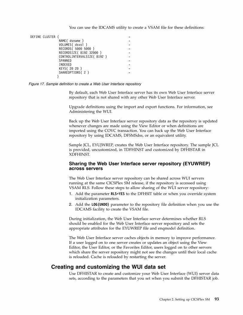
You can use the IDCAMS utility to create a VSAM file for these definitions:
By default, each Web User Interface server has its own Web User Interface serverrepository that is not shared with any other Web User Interface server.
Upgrade definitions using the import and export functions. For information, seeAdministering the WUI.
Back up the Web User Interface server repository data as the repository is updatedwhenever changes are made using the View Editor or when definitions areimported using the COVC transaction. You can back up the Web User Interfacerepository by using IDCAMS, DFSMSdss, or an equivalent utility.
Sample JCL, EYUJWREP, creates the Web User Interface repository. The sample JCLis provided, uncustomized, in TDFHINST and customized by DFHISTAR inXDFHINST.
Sharing the Web User Interface server repository (EYUWREP)across servers
The Web User Interface server repository can be shared across WUI serversrunning at the same CICSPlex SM release, if the repository is accessed usingVSAM RLS. Follow these steps to allow sharing of the WUI server repository:1. Add the parameter RLS=YES to the DFHSIT table or when you override system
initialization parameters.2. Add the LOG(UNDO) parameter to the repository file definition when you use the
IDCAMS facility to create the VSAM file.
During initialization, the Web User Interface server determines whether RLSshould be enabled for the Web User Interface server repository and sets theappropriate attributes for the EYUWREP file and enqmodel definition.
The Web User Interface server caches objects in memory to improve performance.If a user logged on to one server creates or updates an object using the ViewEditor, the User Editor, or the Favorites Editor, users logged on to other serverswhich share the server repository might not see the changes until their local cacheis reloaded. Cache is reloaded by restarting the server.
Creating and customizing the WUI data setUse DFHISTAR to create and customize your Web User Interface (WUI) server datasets, according to the parameters that you set when you submit the DFHISTAR job.
DEFINE CLUSTER ( -NAME( dsname ) -VOLUMES( dsvol ) -RECORDS( 5000 5000 ) -RECORDSIZE( 8192 32000 ) -CONTROLINTERVALSIZE( 8192 ) -SPANNED -INDEXED -KEYS( 20 20 ) -SHAREOPTIONS( 2 ) -)
Figure 17. Sample definition to create a Web User Interface repository
Chapter 2. Setting up CICSPlex SM 93

DFHISTAR postinstallation members for a WUI
When you run DFHISTAR, with a SCOPE of POST or ALL, it creates the followingpostinstallation members for a CICSPlex SM Web User Interface (WUI) server inthe XDFHINST library:v EYUWUIDS – creates and starts all the data sets for a WUI. EYUWUIDS
includes steps to delete the data sets so that you can rerun the job, if required.These deletions are expected to fail the first time that you run the job.EYUWUIDS contains the following steps:– DELWREP deletes the CICSPlex SM WUI data repository, EYUWREP.– DEFWREP defines the CICSPlex SM WUI data repository, EYUWREP.– DELCOVDS deletes the WUI import and export data sets, EYUCOVI and
EYUCOVE– DEFCOVDS defines the WUI import and export data sets, EYUCOVI and
EYUCOVE– JES3DELA and JES3DEFA are included if you specify the DFHISTAR JES=JES3
option. They delete and define the CICS local catalog, the global catalog, andthe local request queue.
– DELREGDS deletes the CICS data sets.– DEFTRACE defines the CICS auxiliary trace data sets, DFHAUXT and
DFHBUXT.– DEFHTML defines the CICS DFHHTML data set.– DEFDMPS defines the CICS transaction dump data sets, DFHDMPA and
DFHDMPB.– DEFTSTD defines the CICS auxiliary temporary storage data set, DFHTEMP.– DEFINTD defines the CICS intrapartition transient data set, DFHINTRA.– DEFLCD defines the CICS local catalog, DFHLCD.– INITLCD uses the DFHCCUTL utility to start the CICS local catalog.– DEFGCD defines the CICS global catalog, DFHGCD.– INITGCD uses the DFHRMUTL utility to start the CICS global catalog.– DEFLRQ defines the CICS local request queue data set, DFHLRQ.– JES3DELA and JES3DELB are included if you specify the DFHISTAR JES=JES3
option. They delete and define the CICS DFHCSD data set.– DELCSD deletes the CICS DFHCSD data set.– DEFCSD defines the CICS DFHCSD data set.– INITCSD uses the DFHCSDUP utility to start the DFHCSD data set.
v EYUJWREP – creates the WUI data repository, EYUWREP. EYUWUIDS includessteps to delete and define EYUWREP. You can run EYUJWREP if you want todelete and define only EYUWREP but none of the other data sets for a WUI.– DELWREP: delete the CICSPlex SM WUI data repository, EYUWREP.– DEFWREP: define the CICSPlex SM WUI data repository, EYUWREP.
v EYUWUISP – CICS system initialization parameter overrides for a WUI.v EYUWUI0P – CICSPlex SM EYUPARM parameters for a WUI.v EYUWUIIN – CICSPlex SM EYUWUI parameters for a WUI.v EYUWUIP – starts a WUI.v EYUWUIJ – invokes EYUWUIP.
If you use the default values for the CICSPlex SM parameters, the EYUWUIPPROC statement is shown in the following code sample:
94 CICS TS for z/OS: CICSPlex SM Concepts and Planning

EYUWUIP PROC DSNCSD=’CICSTS55.CPSM.WUINCM01.DFHCSD’,RGNHLQ=’CICSTS55.CPSM.WUINCM01’,CICSHLQ=’CICSTS55.CICS’,CPSMHLQ=’CICSTS55.CPSM’,PRMLIB=’CICSTS55.XDFHINST’,CICSPRM=EYUWUISP, CICS ParametersCPSMPRM=EYUWUI0P, CPSM ParametersWUIPRM=EYUWUIIN WUI Parameters
Customizing postinstallation jobs using DFHISTAR
You can use DFHISTAR to generate copies of the WUI postinstallation jobs for adifferent CICS region. Use the DFHISTAR SELECT parameter to specify a newname for a copy of a postinstallation job. It has this format:SELECT jobname newname
jobnameIs the name of the job you that want to regenerate
newnameIs the name for the new copy.
You can specify more than one SELECT parameter to select multiple jobs to beregenerated in a single run of the DFHISTAR job. When you include a SELECTparameter in the DFHISTAR job, only those jobs specified by the SELECT aregenerated.
For a WUI with the name WUINCM02 and a CICS system identifier of WU02,which connects to a CMAS with the name CMAS02 and CICS system identifierCM02, you can change your DFHISTAR parameters to specify these options:CMASNAME CMAS02CMSSYSID CM02WUIPLEX WUIPCM02WUINAME WUINCM02WUISYSID WU02TCPIPHST TCP/IP host name for this WUITCPIPPRT TCPIP port number for this WUISELECT EYUWUIDS WU02WUDS JCL to create the data sets for WUINCM02SELECT EYUWUISP WU02WUSP CICS SIT overrides for WUINCM02SELECT EYUWUI0P WU02WU0P CICSPlex SM EYUPARM parameters for WUINCM02SELECT EYUWUIIN WU02WUIN CICSPlex SM EYUWUI parameters for WUINCM02SELECT EYUWUIJ CW02WUIJ JCL statementSELECT EYUWUIP CW02WUIP PROC statement
You can then start the WUI WUINCM02, using the procedure EYUWUIP withthese commands:START EYUWUIP, DSNCSD=’CICSTS55.CPSM.WUINCM02.DFHCSD’,RGNHLQ=’CICSTS55.CPSM.WUINCM02’, CICSHLQ=’CICSTS55.CICS’,CPSMHLQ=’CICSTS55.CPSM’, PRMLIB=’CICSTS55’, CICSPRM=WU02WUSP, CPSMPRM=WU02WU0P,WUIPRM=WU02WUIN
If you are using EYUWUIJ to start the WUI, edit it to specify these values:CICSPRM=WU02WUSP, CSMPRM=WU02WU0P, WUIPRM=WU02WUIN
Specifying the WUI customizable view and menu help data setThe Web User Interface allows a site to provide customized help for individualviews and menus.
Chapter 2. Setting up CICSPlex SM 95

This help takes the form of HTML documents that can be served by the Web UserInterface server or by an external server. If the Web User Interface is to serve theHTML documents, you must provide a partitioned data set to contain the HTMLdocuments.
You can use the View Editor to customize your views and menus to include a linkto the customizable view and menu help data set. With the View Editor you canspecify these options:v No help to be available for this view or menuv Member name of a help page to be served by the Web User Interface from
DFHHTMLv Web address of an external help page to be served by another HTTP server
For information about the View Editor, see Customizing the Web User Interface.
The customizable view and menu help data set (DFHHTML) must be a single dataset and not concatenated with any other data set.
Specifying Web User Interface server initialization parametersYou can specify the Web User Interface (WUI) server initialization parameters inthe startup job or in a fixed block 80 data set.
For a summary of changes by release to CICSPlex SM WUI server initializationparameters, see Changes to CICSPlex SM.
See “Specifying the JCL DD statements for the WUI” on page 106 for the DDname. All of these parameters are subject to the following conditions unlessotherwise stated:v Lines with an asterisk in column 1 are comments and are ignored.v Values must not contain lowercase characters.v Values must be specified in parentheses immediately following the parameter.v Values must not be greater than 32 characters.
Example* An EYUWUI parameter data setDEFAULTMENU(OURHOME)TCPIPHOSTNAME(MVSXX.COMPANY.COM)TCPIPPORT(4445)CMCIPORT(4446)
Required parameters for the WUISet the TCPIPHOSTNAME and TCPIPPORT parameters to initialize the Web UserInterface server. The Web User Interface supports names up to 44 characters inlength for all parameters.
TCPIPHOSTNAME(name)Specify the TCP/IP host name of this Web User Interface server. This name isnormally the host name and domain name of the MVS system; that is, afully-qualified name, but can be a specific IP address in colon hexadecimal ordotted decimal format. The host name is normally used by the Web UserInterface to construct Web addresses, depending on the client HTTP versionand the value of the TCPIPHTTPHOST Web User Interface server parameter.
This value is always returned in the TCPIPHOSTNAME header of aDATA/CONNECT Web User Interface Data Interface request.
96 CICS TS for z/OS: CICSPlex SM Concepts and Planning

TCPIPPORT(value)Specify the TCP/IP port number of the port that you have allocated for theWeb User Interface.
Optional parameters for the WUIYou can specify a number of optional initialization parameters when setting upyour Web User Interface server. Certain parameters are required in certaincircumstances. For example, if you want to use the CICS management clientinterface (CMCI) with CICSPlex SM, you must set the CMCIPORT parameter.
TCP/IP options
You can specify additional TCP/IP options to configure your TCP/IP connections.The Web User Interface supports names up to 44 characters in length for alloptions:
TCPIPADDRESS(name | INADDR_ANY)Specifies the dotted decimal or colon hexadecimal IP address on which theWeb User Interface listens for incoming requests. If INADDR_ANY is specified(the default), the Web User Interface listens on any of the addresses known tothe TCP/IP for z/OS host.
You do not normally have to specify the TCPIPADDRESS option unless thez/OS host has multiple TCP/IP addresses.
TCPIPHTTPHOST(NO|YES)Indicates whether you require the TCP/IP host name used to construct Webaddresses to be generated based on the incoming HTTP request for HTTPversion 1.1 requests or later.
This option has no effect on HTTP requests sent before 1.1 to the Web UserInterface server. The Web User Interface server always constructs Webaddresses using the host name specified in the TCPIPHOSTNAME Web UserInterface server parameter for HTTP 1.0 (and earlier) requests.NO For HTTP 1.1 (or later) requests, the host name used in Web addresses
constructed by the Web User Interface server is based on the valuespecified in the TCPIPHOSTNAME Web User Interface serverparameter.
YES For HTTP 1.1 (or later) requests, the host name used in Web addressesconstructed by the Web User Interface server is based on the incomingURI or HTTP 'Host' header, according to the HTTP 1.1 specification.
When HTTP 1.1 clients are used with a Web User Interface server runningTCPIPHTTPHOST(YES), the IP address or name used on the server, does nothave to be the same as that used by the HTTP 1.1 client. In this way the WebUser Interface can be used when name address translation (NAT) is performed,perhaps because of a firewall.
If TCPIPSSL(YES) is used with TCPIPHTTPHOST(YES) and HTTP 1.1 clientsare used with different IP address names, you might receive SSL certificatewarnings because of host name mismatches.
TCPIPSSL(YES | NO)Indicates whether you require data encryption between your Web UserInterface server and web browser. If you select YES, specify the appropriatesystem initialization parameters to enable SSL support in the CICS WebInterface. For information, see SSL with CICS web support.
Chapter 2. Setting up CICSPlex SM 97

If TCPIPSSL is set to YES, then TCPIPSSLCERT and TCPIPSSLCIPHERS settings willalways apply, unless the optional CMCISSL parameter is set with the NO orATTLSAWARE value.
TCPIPSSLCERT(name)Specifies the label for the SSL certificate that is to be used for the connectionbetween the Web User Interface and the web browser. If you specify an explicitcertificate, the label must be no longer than 44 characters.
The default is the default certificate in the key ring. This field is case-sensitiveand is not converted to uppercase.
TCPIPSSLCIPHERS(cipher_list)The TCPIPSSLCIPHERS attribute can be specified in either of two ways:v A string of up to 44 hexadecimal digits that is interpreted as a list of up to
22 2-digit cipher suite codes.v The name of the SSL cipher suite specification file, which is a z/OS UNIX
file in the security/ciphers subdirectory of the directory that is specified bythe USSCONFIG system initialization parameter. For example if USSCONFIG isset to /var/cicsts/dfhconfig and TCPIPSSLCIPHERS is set tostrongciphers.xml, the fully qualified file name is /var/cicsts/dfhconfig/security/ciphers/strongciphers.xml.
The cipher suite codes are used to describe the set of algorithms that aresupported by the Web User Interface server for SSL communications. If theTCPIPSSLCIPHERS parameter is not specified, the cipher suite is set using theENCRYPTION system initialization option that the Web User Interface server isusing.
For details, see Cipher suites and cipher suite specification files.
CMCI options
You can specify additional parameters to enable the use of CMCI with CICSPlexSM. The defaults for CMCI are derived from the SEC CICS system initializationparameter and the TCPIPSSL WUI server initialization parameter. If TCPIPSSL is setto YES, CMCI will use the TCPIPSSLCERT and TCPIPSSLCIPHERS parameters.
If the optional CMCIAUTH and CMCISSL parameters are specified then the CMCI willuse these parameters to define the level of security. If CMCISSL is set to YES orCLIENTAUTH, CMCI will use the TCPIPSSLCERT and TCPIPSSLCIPHERS parameters.For more information on the TCPIPSERVICE attributes affected by CMCIAUTH andCMCISSL, see TCPIPSERVICE attributes.
CMCIPORT(value)Specifies the TCP/IP port number allocated to the CICS management clientinterface (CMCI). This parameter is required so that you can use CMCI in aCICSPlex SM environment. Specify a number in the range 1 - 65535 but do notuse the same port number as specified for the WUI in the TCPIPPORTparameter. When you set this parameter, TCPIPSERVICE and URIMAPdefinitions are autoinstalled to support CMCI.
CMCIAUTH(NO | BASIC | CERTIFICATE | AUTOREGISTER | AUTOMATIC)Specifies the settings for the CMCI TCPIPSERVICE AUTHENTICATE attribute.If CMCIAUTH is specified then CMCISSL must also be specified.
CMCISSL(NO | YES | CLIENTAUTH | ATTLSAWARE)Specifies the settings for the CMCI TCPIPSERVICE SSL attribute. If CMCISSL isspecified then CMCIAUTH must also be specified.
98 CICS TS for z/OS: CICSPlex SM Concepts and Planning

Note: TCPIPSSLCERT and TCPIPSSLCIPHERS settings are ignored when thisparameter is set with the NO or ATTLSAWARE value.
Import options
The import options allow you to automatically import WUI data repositorydefinitions from the Web User Interface. The WUI data repository includes viewsets and menus, WUI map objects, user objects, and user group profiles.Definitions can be imported from a specified transient data queue or a data set, orboth.
Auto-import is an alternative to the import function of the COVC transaction.When you use auto-import, you can use all three parameters to specify a transientdata queue and a data set. When using COVC, you are restricted to specifyingeither a transient data queue or a data set in one import operation.
AUTOIMPORTDSN(dsn_name)Specifies the name of the data set containing IBM-supplied view and menudefinitions. Currently, the supplied set of WUI view and menu definitions is inthe SEYUVIEW data set. If you specify an AUTOIMPORTDSN name, you mustspecify the name of a data set member using the AUTOIMPORTMEMparameter.
Use the AUTOIMPORTDSN and AUTOIMPORTMEM parameters when youwant to import specific IBM-supplied view set and menu definitions as a resultof service (by a PTF).
AUTOIMPORTMEM(member_name)Specifies the name of the data set member containing the specific IBM-suppliedview and menu definitions that you want to import. You can use an asterisk atthe end of the name to specify a group of data set members that begin withthe same characters. For example, specifying AUTOIMPORTMEM(EYUEA*)with the IBM-supplied SEYUVIEW data set in AUTOIMPORTDSN imports allof the members beginning with the characters EYUEA.
Use the AUTOIMPORTDSN and AUTOIMPORTMEM parameters when youwant to import specific IBM-supplied view set and menu definitions as a resultof service (by a PTF).
AUTOIMPORTTDQ(tdq_name)Specifies the name of the CICS extrapartition transient data queue from whichyou want the server to import a complete set of WUI data repositorydefinitions during server initialization. To use this option, you enter a valueexplicitly. There is no automatic default; however, queue name COVI (DDname EYUCOVI) is defined as shown in sample EYU£WDEF.
You use the AUTOIMPORTTDQ parameter when starting a WUI server for thefirst time or if you are already a CICSPlex SM user and want to import otherdata repository definitions, including your own customized definitions, into anexisting data set. Avoid using this parameter at other times because of theresources required to perform the import operation.
Data formatting options
These options determine how data appears on Web User Interface displays.
CVDASTYLE(MIXED | UPPER)Indicates whether the CVDAs and EYUDAs are displayed in uppercase ormixed case characters.
Chapter 2. Setting up CICSPlex SM 99

MIXEDMixed case text, that is, the first character uppercase and the restlowercase, for example, 'Enabled'.
UPPERText is displayed in uppercase only.
DATEFORMAT (format | MMDDYY)Specifies the format to be used to display the date on Web User Interfacedisplays:
YYMMDD
DDMMYY
MMDDYY
YYYYMMDD
DDMMYYYY
MMDDYYYY
where:
DD is the day.
MM is the month.
YY is the year in two-digit format.
YYYY is the year in four-digit format.
DATESEPARATOR(character | / )Specifies the character to be used to separate the date elements on Web UserInterface displays.
DECIMALSEPARATOR(character | . )Specifies the character to be used to denote the decimal point on Web UserInterface displays.
GMMTEXTMSG( NO | YES | BEFORE | AFTER)Specifies how the CICS "good morning" message is handled.
NO The message is not issued
YES The message is issued before and after sign-on.
BEFOREThe message is issued before sign-on only.
AFTERThe message is issued after sign-on only.
MSGCASE (MIXED | UPPER)Indicate whether messages destined for the operator or EYULOGs should bedisplayed in mixed case or uppercase characters.
MIXEDMixed case text is displayed, that is, the first character uppercase andthe rest lowercase, for example, 'Enabled'.
If you specify MIXED, output may be displayed incorrectly onKatakana display terminals, where lowercase characters are displayedas Katakana symbols.
UPPERText is displayed in uppercase only.
100 CICS TS for z/OS: CICSPlex SM Concepts and Planning

Note that while MSGCASE(MIXED) is the default, it takes effect after all theEYUWUI parameters have been read. Certain EYUWUI parameters such asTCPIPSSLCERT may contain values that are in mixed case. They will beechoed back in the EYULOG in uppercase unless MSGCASE(MIXED) is thefirst parameter in the EYUWUI input stream.
THOUSNDSEPARATOR(character | , )Specifies the character to be used to separate thousands on Web User Interfacedisplays, when required. For example, 100 000 is displayed as 100,000 if thedefault is used.1. The space character (hex 40) is a valid THOUSNDSEPARATOR value,
allowing digits to be grouped by a space.2. Use 0 (zero) to suppress the THOUSNDSEPARATOR value.3. The THOUSNDSEPARATOR value is used only when required by the
individual view definition.
TIMESEPARATOR(character | : )Specifies the character to be used to separate hours, minutes, and seconds onWeb User Interface displays.
Environment options
These options specify the context and scope values, the home menu and navigationframe, default map objects, and the appearance of newly opened maps.
AUTOREFRESH(YES | NO)Disables the automatic refresh option for a WUI server. The default setting,YES, displays automatic refresh control, based on the view definition. WhenNO is specified, automatic refresh control is not displayed, even if automaticrefresh control is set on the view definition. For more information about theautomatic refresh option, see Refreshing views.
DEFAULTCMASCTXT(name | EYUCMS1A)Specifies the CMAS context that is set when the user signs on to the Web UserInterface.
DEFAULTCONTEXT(name | EYUPLX01)Specifies the context that is set when the user signs on to the Web UserInterface.
DEFAULTMAPBAS(name | EYUSTARTMAPBAS)Specifies the name of the map object used to generate maps of businessapplication services definitions.
DEFAULTMAPCOLL(value | 0)Specifies the number of rows in a generated map below which a map opens inthe expanded state. If the number of rows to be displayed is above thisnumber, the map opens in a fully collapsed state. The default value of 0 meansthat in every generated map all of the rows are visible when opened.
DEFAULTMAPMON(name | EYUSTARTMAPMON)Specifies the name of the map object used to generate maps of monitoringdefinitions.
DEFAULTMAPRTA(name | EYUSTARTMAPRTA)Specifies the name of the map object used to generate maps ofreal-time-analysis definitions.
Chapter 2. Setting up CICSPlex SM 101

DEFAULTMAPWLM(name | EYUSTARTMAPWLM)Specifies the name of the map object used to generate maps of workloadmanagement definitions.
DEFAULTMENU(name | EYUSTARTMENU)Specifies the name of the menu that is presented to users after sign-on to theWeb User Interface.
DEFAULTNAVIGATE(name | EYUSTARTNAVIGATE)Specifies the name of the navigation frame that is presented to users aftersign-on to the Web User Interface.
DEFAULTSCOPE(name | EYUPLX01)Specifies the scope that is set when the user signs on to the Web User Interface.
DEFAULTWARNCNT(value)Specifies the number of records required to trigger the record count warningmechanism. This integer value is in the range of 0 to 99999999, the defaultvalue is 0 meaning that no warnings are issued. This option affects thebehavior of both the WUI and the CICS management client interface (CMCI).
For the WUI only, you can also set a record count warning value applying to agroup of users when setting up a WUI user group; settingDEFAULTWARNCNT in a user group applies to the WUI only if the WUI isrunning with security switched on. A value set in a user group takesprecedence over a value set in the DEFAULTWARNCNT parameter for theusers in that group.
GLOBALPREFILTER(YES | NO)Specifies filter parameters the first time that a view is displayed; that is, beforedata is collected. You can also specify this parameter when setting up a WUIuser group if the WUI is running with security enabled. A value set in a usergroup takes precedence, for users in that group, over the value set in theGLOBALPREFILTER parameter.
RESOURCELIMIT(WARNING | FAIL)Specifies whether a warning or failure is issued when the resource limit isreached.
WARNINGFor the WUI only, the default setting, WARNING, issues messageEYUVC1258W, and the user can select OK to bypass the warningthreshold.
For the CMCI only, the CMCI responds with an HTTP 403 responseincluding message DFHWU4302. The user can bypass the warningthreshold by using the CMCI request URI optionOVERRIDEWARNINGCOUNT.
FAIL For the WUI only, specify FAIL to issue message EYUVC1267E anddeny the new resource request.
For the CMCI only, the CMCI responds with an HTTP 403 responseincluding message DFHWU4302 denying the new resource request.
Operation options
These options name the default view set to be used if the Web User Interfacereceives an external request that does not specify a view set name but specifies an
102 CICS TS for z/OS: CICSPlex SM Concepts and Planning

object name. The view sets that you name in these options must represent theobjects that can be specified. For more information, see Providing access to WUIviews and menus.
You can ignore these parameters if you do not intend to launch Web User Interfacedisplays in this manner.
DEFAULTCICSPLEX(name | EYUSTARTCICSPLEX)Specifies the name of the default CICSplex view set.
DEFAULTCICSRGN(name | EYUSTARTCICSRGN)Specifies the name of the default CICS region view set.
DEFAULTCONNECT(name | EYUSTARTCONNECT)Specifies the name of the default connection view set.
DEFAULTCSYSGRP(name | EYUSTARTCSYSGRP)Specifies the name of the default CICS system group view set.
DEFAULTDB2SS(name | EYUSTARTDB2SS)Specifies the name of the default Db2 subsystem view set.
DEFAULTEJCOBEAN(name | EYUSTARTEJCOBEAN)Specifies the name of the default enterprise bean in a CorbaServer view set.
DEFAULTEJDJBEAN(name | EYUSTARTEJDJBEAN)Specifies the name of the default enterprise bean in a CICS-deployed JAR fileview set.
DEFAULTEVENT(name | EYUSTARTEVENT)Specifies the name of the default event view set.
DEFAULTLOCFILE(name | EYUSTARTLOCFILE)Specifies the name of the default local file view set.
DEFAULTLOCTRAN(name | EYUSTARTLOCTRAN)Specifies the name of the default local transaction view set.
DEFAULTPROGRAM(name | EYUSTARTPROGRAM)Specifies the name of the default program view set.
DEFAULTREMFILE(name | EYUSTARTREMFILE)Specifies the name of the default remote file view set.
DEFAULTREMTRAN(name | EYUSTARTREMTRAN)Specifies the name of the default remote transaction view set.
DEFAULTTASK(name | EYUSTARTTASK)Specifies the name of the default task view set.
User options
These options specify user settings that you can configure.
INACTIVETIMEOUT(value | 30)Specifies the period, in minutes, after which inactive user sessions are ended.The maximum period allowed is 10080 minutes (7 days).
MAXUSERS(value | 20)Specifies the maximum number of concurrent users of the Web User Interface.The maximum number of concurrent users allowed is 50.
SIGNONPANEL(BASIC | ENHANCED)Specifies, if the Web user Interface server has CICS security active (SEC=YES in
Chapter 2. Setting up CICSPlex SM 103

the system initialization parameter), whether the Web User Interface sign onpanel takes one of the following actions:v Displays a GROUP optionv Saves previously used USER and GROUP valuesv Positions the cursor in the sign-on field requiring input
When the default value, ENHANCED, is specified, the GROUP option isdisplayed on the sign-on screen and the following events occur:v If the user enters a value, sign on proceeds and if:
– The user ID is connected to the specified group, the group is used for theWUI user group profile
– The user ID is not connected to the specified group or the group name isnot valid, sign on continues, but the WUI group profile is set to thedefault group of the user, and message EYUVC1227W is issued to theWUI user after sign on is complete. Message EYUVS0024W is written tothe WUI server's EYULOG.
v If the user does not enter a value, the user group profile is set to the defaultgroup of the user
The GROUP option does not change the current connect group of the userbeing signed on. The security environment built by the WUI is always basedon the default group of the user. The group option on the WUI sign-on screenspecifies which WUI user group profile the user should be associated with anddoes not change any security decisions that might be made by the ExternalSecurity Manager.
When the SIGNONPANEL(ENHANCED) option is set and JavaScript isenabled in the web browser, the sign-on process performs the followingactions:v Saves the user ID and group values in a cookie, so that when the sign-on
process next runs, the form is filled with previously entered valuesv Positions the cursor to the sign-on field requiring input
When the value, BASIC, is specified, the GROUP option is not displayed onthe sign on screen, and the user group profile is set to the default group of theuser. Values are not saved and the cursor is not positioned on the sign-onpanel.
Whether the Web User Interface user group profile is set based on the defaultgroup, or specified on the GROUP option, if no matching Web User Interfacegroup profile is found, the values usually set using a user group profile are setto the system default.
The SIGNONPANEL option is ignored if the Web User Interface server isrunning with CICS Security inactive (SEC=NO in the system initializationparameter).
Accessibility options
These options specify the default colors for the Web User Interface displays.
The accessibility options are not normally changed as they affect all users of theWeb User Interface server. If you want to change these options for reasons ofaccessibility, take care to ensure that the Web User Interface displays do notbecome unreadable.
104 CICS TS for z/OS: CICSPlex SM Concepts and Planning

Each option specifies a color as six hexadecimal digits. The first 2 digits describethe red component. The second 2 digits describe the green component. The last 2digits describe the blue component. For example, FFFFFF represents white, 000000represents black, FF0000 represents bright red, 00FF00 represents bright green, and0000FF represents bright blue.
COLORPAPER(color)Main work frame background color.
COLORPAPERHEAVY(color)Navigation and assistance frame background color.
COLORPAPERLIGHT(color)Background color used for many interface items; for example, informationmessages, table column headings, detail view labels, view selection and refresharea.
COLORPAPERWARN(color)Background color for warning messages.
COLORPAPERERROR(color)Background color for error messages.
COLORPAPERALT(color)Background color for alternate rows on tabular displays.
COLORPAPERRULE(color)Background color for assistance frame bar containing the navigation and helpicons.
COLORINK(color)Main work frame text color.
COLORINKBANNER(color)Navigation and assistance frame text color.
COLORINKLINK(color)Unvisited link text color.
COLORINKVLINK(color)Visited link text color.
Problem determination option
This option allows you to specify the level of tracing you require for the Web UserInterface server.
Attention: Only activate trace at the request of IBM Support Center personnel.
WUITRACE(trace levels)Specifies the level of tracing for the Web User Interface server.
The trace levels that you specify must be separated by a comma, as shown inthis example:WUITRACE(8,11,13,15,18)
You can define a range of trace levels as shown in these examples:WUITRACE(1:5)
activates trace levels 1 through 5
WUITRACE(1:5,13,28:31)activates trace levels 1 through 5, 13, and 28 through 31
Chapter 2. Setting up CICSPlex SM 105

Creating transient data queue definitions for the WUIYou require definitions for the COVP, COLG, COVI and COVE transient dataqueues (TDQs).
COVP The Web User Interface server initialization parameters data set, EYUWUI.This data set is a fixed block 80 input data set.
COLG The CICSPlex SM output log, EYULOG. This data set is a variable-lengthoutput data set.
COVI Sample definition for the Web User Interface import data set, EYUCOVI.This data set is a variable-length input data set.
COVE Sample definition for the Web User Interface export data set, EYUCOVE.This data set is a variable-length output data set.
CICS Transaction Server definitions
The transient data queue (TDQ) definitions are provided in the EYU$WDEFsample, which is supplied in the SEYUSAMP library. COVI and COVE areprovided as samples that can be used to create additional import and exporttransient data queues.
Specifying the JCL DD statements for the WUIAdd DD statements to the Web User Interface server for the EYUWUI, EYUWREP,EYULOG, DFHHTML, EYUCOVI and EYUCOVE data sets.
EYUWUIThe Web User Interface server initialization parameters data set. See“Specifying Web User Interface server initialization parameters” on page96.
EYUWREPThe Web User Interface server repository data set. See “Creating the WebUser Interface server repository (EYUWREP)” on page 92.
EYULOGThe CICSPlex SM output log.
DFHHTMLThe customizable view and menu help data set. See “Specifying the WUIcustomizable view and menu help data set” on page 95. This statement isoptional.
EYUCOVIThe Web User Interface server import data set. For more information, see“Creating transient data queue definitions for the WUI.” This statement isoptional.
EYUCOVEThe Web User Interface server export data set. For more information see“Creating transient data queue definitions for the WUI.” This is statementoptional.
Here is an example://*//DFHHTML DD DISP=SHR,DSN=data set name//EYUWREP DD DISP=SHR,DSN=data set name//EYUCOVI DD DISP=SHR,DSN=data set name//EYULOG DD SYSOUT=*//EYUWUI DD *
106 CICS TS for z/OS: CICSPlex SM Concepts and Planning

DEFAULTMENU(OURHOME)TCPIPHOSTNAME(MVSXX.COMPANY.COM)TCPIPPORT(4445)/*
Starting and stopping the Web User InterfaceAfter you have set up the Web User Interface, you must complete some additionaltasks.
Submitting startup JCL
Submit the startup JCL for the Web User Interface server to start it for the firsttime.
Messages on the job log are displayed to confirm that the Web User Interfaceserver has started successfully.08.52.33 JOB03331 +EYUVS0001I IYCQCTA5 CICSPLEX SM WEB USER INTERFACE INITIALIZATION STARTED.08.52.37 JOB03331 +EYUVS0002I IYCQCTA5 CICSPlex SM Web User Interface initialization complete.
If you choose not to start the Web User Interface server during PLTPI processing,you can start it using the COVC transaction Start command.
Checking the web browser connection
Check the connection between the Web User Interface and the web browser bytyping in the web address: http://hostname:port/CICSPlexSM.
hostname is the name specified on the TCPIPHOSTNAME Web User Interfaceserver initialization parameter and port is the value specified on the TCPIPPORTWeb User Interface server initialization parameter.
For information about the Web User Interface server initialization parameters, see“Specifying Web User Interface server initialization parameters” on page 96. Youare presented with the Web User Interface server Welcome panel containing aBegin Signon button.
Obtaining view and menu definitions
When the Web User Interface has been started, you can obtain some view andmenu definitions. You can obtain these views in two ways:v Log in to the CICS terminal and run the COVC transaction. Use the Import
option of the COVC transaction to import the starter set views and menus. Thestarter set views and menus are provided in CICSTS55.CPSM.SEYUVIEW. Forinformation about the COVC transaction, see The CICSPlex SM Web UserInterface transaction (COVC).
v Use the View Editor, which is described in Using the view editor in Configuring.
Shutting down the Web User Interface server
You can shut down the Web User Interface server by shutting down the CICSsystem in which the Web User Interface server is running, or by using the COVCtransaction. For more information about the COVC transaction, see The CICSPlexSM Web User Interface transaction (COVC).
Chapter 2. Setting up CICSPlex SM 107

Setting up CMCI for HTTP system management clientsTo configure and manage CICS regions from an HTTP system management clientsuch as CICS Explorer, you must set up the CICS management client interface(CMCI) in your CICS environment.
About this task
You can set up the CMCI in a CICSPlex SM environment or in a stand-alone CICSregion (SMSS).
If you use CMCI with CICSPlex SM, with an HTTP client such as CICS Explorer,users can manage definitional, operational, and CSD resources in all of the CICSregions managed by CICSPlex SM.
If you use CMCI in a stand-alone CICS region (SMSS), with an HTTP client suchas CICS Explorer, users can manage only the operational and CSD resourcesassociated with that region, and the context is specified as the application ID ofthat CICS region.
Setting up CMCI with CICSPlex SMTo install the CICS management client interface (CMCI) in a CICSPlex SMenvironment, you must configure CMCI in a WUI region.
Planning for CMCI setup1. It is recommended that CMCI is set up on a dedicated CICSPlex SM WUI
region. This WUI region is to serve all connection requests from HTTP systemmanagement clients, while another CICSPlex SM WUI region is a dedicatedCICSPlex SM WUI web server.
2. For high availability, you can have multiple CICSPlex SM WUI regions that areset up with CMCI running in your CICSPlex SM environment.
3. It is strongly recommended to use the CMCI JVM server with CMCI. TheCMCI JVM server provides support for client authentication and the GraphQLAPI.It is still possible to use CMCI without the CMCI JVM server. However, somefeatures, such as support for multi-factor authentication (MFA) and support forthe CMCI GraphQL API, will not be available.
Note: This CMCI configuration procedure assumes that you use the CMCI JVMserver with CMCI. If do not want to use this, use the instructions in Setting upCMCI with CICSPlex SM in the CICS TS 54 product information.
Before you begin
One or more CICSPlex SM WUI regions have been configured for CMCI setup. Toset up a CICSPlex SM WUI region, follow Setting up a CICSPlex SM Web UserInterface server.
Setup guide
Scenario 1: You want to set up CMCI in a WUI region that does not have CMCIconfigured
Follow the instructions in “Configuring CMCI in a WUI region” on page109.
108 CICS TS for z/OS: CICSPlex SM Concepts and Planning
|
||
|
||||
||
|||
|||
|||
|
|||
|
||
||
Scenario 2: You have a WUI region that is already set up with CMCI but it doesnot use the CMCI JVM server. You want to upgrade the WUI region to use theCMCI JVM server.
For instructions, see “Configuring a WUI region to use the CMCI JVMserver” on page 113.
Scenario 3: You want to have several CMCI JVM servers running in a CICSplex
If you have several CMCI JVM servers running in a CICSplex, you canconfigure the single sign-on (SSO) support in Liberty to enable HTTP clientusers to authenticate once with one CMCI JVM server, thus having accessto other CMCI JVM servers in the same CICSplex withoutre-authentication. For instructions, see “Setting up for multiple CMCI JVMservers in a CICSplex” on page 116.
Configuring CMCI in a WUI regionIf a WUI region does not have CMCI, you can set up CMCI in this WUI region.This procedure assumes that you will use the CMCI JVM server with CMCI.
If you opt not to use the CMCI JVM server, follow the instructions in Setting upCMCI with CICSPlex SM in the CICS TS 54 product information.
Before you begin
System requirements for the CMCI JVM server
1. Verify that all of the required Java components are installed. You canfollow the Java components checklist.
2. Ensure that Java support is set up in the region. For instructions, seeSetting up Java support.
Additional requirements for enabling connections with multi-factorauthentication (MFA) credentials
v You must have IBM Multi-Factor Authentication for z/OS or anequivalent product configured with RACF to support multi-factorauthentication. If you use an alternative external security manager(ESM), refer to your vendor for details.
v MFA is supported by CICS TS V5.4 with APAR PI87691 or later. Ensurethat the region where the CMCI JVM server will be running, and theCMAS are at the same CICS level that is CICS TS V5.4 with APARPI87691 or later. For information about CICS level considerations forsetting up your CICSPlex SM topology, see Designing your CICSPlex SMenvironment.
Additional requirements for the GraphQL API feature
v The region is at CICS TS 5.5 open beta or later.
Procedure1. Specify appropriate levels of 64-bit (above-the-bar) storage in the region, and
auxiliary storage, as follows:v Use the z/OS MEMLIMIT parameter to set the limit for 64-bit storage in the
regionv Use the MAXAUXCPSM and MAXAUXTOTL CICSPlex SM system parameters, to set
auxiliary storage for the CMAS.See “Estimating storage requirements for CMCI” on page 123 for guidanceabout setting these values to avoid possible storage problems.
Chapter 2. Setting up CICSPlex SM 109
|||
||
|
||||||
|||
||
|
|
||
||
||
||||
||||||
|
|
|
||
||
||
||

2. Ensure that the CICS system initialization parameter CSDSTRNO is at least four(CSDSTRNO=4) so that CICS Explorer can inquire on CICS resources on the CSD,for example, programs, files, or transactions.If CSDSTRNO is lower than four, the request might fail with CNX0591ERESP=CSDERR RESP2=5 (insufficient VSAM strings).
3. Review the values of KEYRING, NISTSP800131A, and SEC system initializationparameters. These system initialization parameters, together with APPLID andDFLTUSER, are mapped to the CMCI JVM server configuration parameters. Youshould know how these values are mapped. Be aware that in some cases,additional configuration might be required in the CMCI JVM server. For moreinformation, see “Configuration parameter mapping between CICSPlex SMWUI server and CMCI JVM server” on page 116.
4. Specify WUI server initialization parameters to enable the use of CMCI withCICSPlex SM. These parameters include CMCI options, TCP/IP options,environment options, and so on.When you specify the WUI server initialization parameters, consider thefollowing issues:v You must specify a unique value for the CMCIPORT parameter. This
parameter allocates a TCP/IP port number to CMCI. Setting a value for theCMCIPORT parameter ensures that CMCI is installed on the WUI region withthe necessary URIMAP and TCPIPSERVICE definitions. CMCI must use adifferent TCPIPSERVICE definition to the WUI region.
v By default, URIMAP, and TCPIPSERVICE resource definitions areautoinstalled with security settings derived from the SEC CICS systeminitialization parameter and the TCPIPSSL WUI server initializationparameter. You can override the default CMCI TCPIPSERVICE settings byusing the optional CMCIAUTH and CMCISSL parameters to enable SSLcertification for greater security. See CICSPlex SM Web User Interfacesecurity access overview for more information about setting up security forthe WUI.
v Consider setting a nonzero value for the DEFAULTWARNCNT WUI serverinitialization parameter. Setting an appropriate value for this parameterprevents the retrieval of unacceptable amounts of data and can avoid longwaits and potential storage problems when making requests on CICSresources. See “Record count warnings in CMCI” on page 119 for guidanceabout the warning count mechanism in CMCI.
For detailed instructions, see Web User Interface server initializationparameters.
Note: It is helpful to know how the WUI server initialization parameters suchas the CMCI options and TCP/IP options are mapped to the CMCI JVMserver configuration parameters. Be aware that some values are notcompatible with the CMCI JVM server. For more information, see“Configuration parameter mapping between CICSPlex SM WUI server andCMCI JVM server” on page 116.
5. Ensure that resource definition group DFHWU is installed. Group DFHWUcontains the resource definitions that are required for a CMCI environment.
Configuring the CMCI JVM server
6. Add the following system initialization parameters to the region:v USSHOME
v JVMPROFILEDIR
v START=INITIAL
110 CICS TS for z/OS: CICSPlex SM Concepts and Planning
|||
||
|||||||
|||
||
|||||
||||||||
||||||
||
||||||
||
|
|
|
|
|

v EDSALIM
Note: The CMCI JVM server needs at least 400 MB of 31-bit storage inaddition to the value specified on EDSALIM. For details, see Calculatingstorage requirements for JVM servers .
7. Create the JVM profile for the CMCI JVM server.a. Copy EYUCMCIJ.jvmprofile from /usr/lpp/cics55/JVMProfiles to the
location that is specified in the JVMPROFILEDIR system initializationparameter.
b. Validate or update the values of JAVA_HOME and WORK_DIR in the JVMprofile. For details, see Symbols used in the JVM profile.
8. Configure the Liberty angel process started task for the CMCI JVM server.a. If you don't have a Liberty angel process running, follow the steps in The
Liberty server angel process to create one.b. If you already have a Liberty angel process running, ensure the version of
Liberty specified in the ROOT symbolic parameter in the angel JCL is atthe same or a higher level to the version of Liberty supplied with CICS.
Example: Identifying the Liberty version from the started task system log
If the Liberty angel process is running Liberty 18.0.0.2 or above, the startedtask system log contains a message that indicates the Liberty version:
CWWKB0079I THE ANGEL BUILD LEVEL IS 18.0.0.2 20180619-0654 2018.7.0.0 20180619-0654
Example: Identifying the Liberty version from message DFHSJ1405
The version of a Liberty running in a CICS JVM server is available in thefollowing message:
DFHSJ1405I 08/22/2018 17:04:39 IYK3ZDRI JVMSERVER EYUCMCIJ is running WebSphere Application ServerVersion 18.0.0.2 Liberty - (18.0.0.2-cl180220180619-0403) process ID 67174497.
Example: Identifying the Liberty version by running scripts
Suppose that the angel JCL specifies the following ROOT parameter:// SET ROOT=’/usr/lpp/zosmf/wlp’,
To find out what the version of Liberty is, run the following script:/usr/lpp/zosmf/wlp/bin/productInfo version --verbose
For CICS, run the following script:/usr/lpp/cicsts55/wlp/bin/productInfo version --verbose
Chapter 2. Setting up CICSPlex SM 111
|
|||
|
|||
||
|
||
|||
|
||
|
|
||
||
|
|
|
|
|
|
|
|

c. If the version of Liberty is at a lower level to the version of Libertysupplied with CICS, configure a named angel process using the CICSLiberty install:1) Uncomment the following line in the JVM profile for the CMCI JVM
server, EYUCMCIJ.jvmprofile:#-Dcom.ibm.ws.zos.core.angelName=<named_angel>
2) Specify the angel name in the -Dcom.ibm.ws.zos.core.angelNameproperty.This property enables the CMCI JVM server to connect to the namedangel process. For details, see The Liberty server angel process.
d. Ensure that the Liberty angel process is ready before starting the region.9. Configure security for the region to use the Liberty angel process.
a. Take a copy of the CLIST EYU$ANGL in SEYUSAMP.b. Update the copy with the region userid and the name of your named
angel (if you are using one).c. Run the CLIST.
10. Update the region JCL to include new DD statements for CMCI diagnostics.//JVMOUT DD SYSOUT=*,LRECL=1024//JVMERR DD SYSOUT=*,LRECL=1024//JVMTRACE DD SYSOUT=*,LRECL=1024//MSGLOG DD SYSOUT=*,LRECL=1024
11. Set the following feature toggle to enable the use of the CMCI JVM server.com.ibm.cics.cmci.jvmserver=true
For detailed instructions, see Specifying feature toggles.
WebSphereApplicationServer.properties:com.ibm.websphere.productId=com.ibm.websphere.appservercom.ibm.websphere.productOwner=IBMcom.ibm.websphere.productVersion=16.0.0.3com.ibm.websphere.productName=WebSphere Application Servercom.ibm.websphere.productInstallType=Archivecom.ibm.websphere.productEdition=zOScom.ibm.websphere.productLicenseType=IPLA
WebSphereApplicationServerZOS.properties:com.ibm.websphere.productId=com.ibm.websphere.appserver.zoscom.ibm.websphere.productOwner=IBM CORPcom.ibm.websphere.productVersion=16.0.0.3 <== Liberty Versioncom.ibm.websphere.productName=WAS FOR Z/OScom.ibm.websphere.productPID=5655-WAScom.ibm.websphere.productQualifier=WAS Z/OScom.ibm.websphere.productReplaces=com.ibm.websphere.appservercom.ibm.websphere.productEdition=com.ibm.websphere.gssp=true
zOSMF.properties:com.ibm.websphere.productId=com.ibm.zoszmfcom.ibm.websphere.productOwner=IBMcom.ibm.websphere.productVersion=2.2.0com.ibm.websphere.productName=z/OSMFcom.ibm.websphere.productPID=5650-ZOScom.ibm.websphere.productQualifier=z/OSMFcom.ibm.websphere.productReplaces=com.ibm.websphere.appserver.zoscom.ibm.websphere.productEdition=N/A
Figure 18. Example output
112 CICS TS for z/OS: CICSPlex SM Concepts and Planning
|||||||||||||||||||||||||||||||||||
||
|
||
||
|
|
|
||
|
|
||||
|
|
|

12. Enable users to authenticate through the CMCI JVM server. You must giveusers access to authenticate with the CMCI JVM server, including theauthority to use CMCI.a. Take a copy of the CLIST EYU$CMCI in SEYUSAMP.b. Update the copy with your region userid, applid and a list of groups or
userids of users.c. Run the CLIST.
What to do next
If you want to limit clients that can connect to the CMCI JVM server, you candefine a client whitelist to the CMCI JVM server. For instructions, see “Defining aclient whitelist to CMCI JVM server” on page 124.
Configuring a WUI region to use the CMCI JVM serverIf a WUI region has CMCI configured with the CMCI JVM server disabled, youcan upgrade the WUI region to use the CMCI JVM server.
Before you begin
System requirements for the CMCI JVM server
1. Verify that all of the required Java components are installed. You canfollow the Java components checklist.
2. Ensure that Java support is set up in the region. For instructions, seeSetting up Java support.
Additional requirements for enabling connections with multi-factorauthentication (MFA) credentials
v You must have IBM Multi-Factor Authentication for z/OS or anequivalent product configured with RACF to support multi-factorauthentication. If you use an alternative external security manager(ESM), refer to your vendor for details.
v MFA is supported by CICS TS V5.4 with APAR PI87691 or later. Ensurethat the region where the CMCI JVM server will be running, and theCMAS are at the same CICS level that is CICS TS V5.4 with APARPI87691 or later. For information about CICS level considerations forsetting up your CICSPlex SM topology, see Designing your CICSPlex SMenvironment.
Additional requirements for the GraphQL API feature
v The region is at CICS TS 5.5 open beta or later.
About this task
You must configure and enable the use of the CMCI JVM server in the WUI region.
Procedure1. Add the following system initialization parameters to the region:v USSHOME
v JVMPROFILEDIR
v START=INITIAL
v EDSALIM
Chapter 2. Setting up CICSPlex SM 113
|||
|
||
|
|
|||
|||
|
|
||
||
||
||||
||||||
|
|
|
|
|
|
|
|
|
|
Note: The CMCI JVM server needs at least 400 MB of 31-bit storage inaddition to the value specified on EDSALIM. For details, see Calculatingstorage requirements for JVM servers .
2. Review the values of KEYRING, NISTSP800131A, and SEC system initializationparameters. These system initialization parameters, together with APPLID andDFLTUSER, are mapped to the CMCI JVM server configuration parameters. Youshould know how these values are mapped. Be aware that in some cases,additional configuration might be required in the CMCI JVM server. For moreinformation, see “Configuration parameter mapping between CICSPlex SMWUI server and CMCI JVM server” on page 116.
3. Review your WUI server initialization parameters such as CMCI options andTCP/IP options. You might need to change some values that are incompatiblewith the CMCI JVM server. For details, see “Configuration parameter mappingbetween CICSPlex SM WUI server and CMCI JVM server” on page 116.
4. Create the JVM profile for the CMCI JVM server.a. Copy EYUCMCIJ.jvmprofile from /usr/lpp/cics55/JVMProfiles to the
location that is specified in the JVMPROFILEDIR system initializationparameter.
b. Validate or update the values of JAVA_HOME and WORK_DIR in the JVM profile.For details, see Symbols used in the JVM profile.
5. Configure the Liberty angel process started task for the CMCI JVM server.a. If you don't have a Liberty angel process running, follow the steps in The
Liberty server angel process to create one.b. If you already have a Liberty angel process running, ensure the version of
Liberty specified in the ROOT symbolic parameter in the angel JCL is at thesame or a higher level to the version of Liberty supplied with CICS.
Example: Identifying the Liberty version from the started task system log
If the Liberty angel process is running Liberty 18.0.0.2 or above, the startedtask system log contains a message that indicates the Liberty version:
CWWKB0079I THE ANGEL BUILD LEVEL IS 18.0.0.2 20180619-0654 2018.7.0.0 20180619-0654
Example: Identifying the Liberty version from message DFHSJ1405
The version of a Liberty running in a CICS JVM server is available in thefollowing message:
DFHSJ1405I 08/22/2018 17:04:39 IYK3ZDRI JVMSERVER EYUCMCIJ is running WebSphere Application ServerVersion 18.0.0.2 Liberty - (18.0.0.2-cl180220180619-0403) process ID 67174497.
Example: Identifying the Liberty version by running scripts
Suppose that the angel JCL specifies the following ROOT parameter:// SET ROOT=’/usr/lpp/zosmf/wlp’,
To find out what the version of Liberty is, run the following script:/usr/lpp/zosmf/wlp/bin/productInfo version --verbose
For CICS, run the following script:/usr/lpp/cicsts55/wlp/bin/productInfo version --verbose
114 CICS TS for z/OS: CICSPlex SM Concepts and Planning
|||
|||||||
||||
|
|||
||
|
||
|||
|
||
|
|
||
||
|
|
|
|
|
|
|
|

c. If the version of Liberty is at a lower level to the version of Liberty suppliedwith CICS, configure a named angel process using the CICS Liberty install:1) Uncomment the following line in the JVM profile for the CMCI JVM
server, EYUCMCIJ.jvmprofile:#-Dcom.ibm.ws.zos.core.angelName=<named_angel>
2) Specify the angel name in the -Dcom.ibm.ws.zos.core.angelNameproperty.This property enables the CMCI JVM server to connect to the namedangel process. For details, see The Liberty server angel process.
d. Ensure that the Liberty angel process is ready before starting the region.6. Configure security for the region to use the Liberty angel process.
a. Take a copy of the CLIST EYU$ANGL in SEYUSAMP.b. Update the copy with the region userid and the name of your named angel
(if you are using one).c. Run the CLIST.
7. Update the region JCL to include new DD statements for CMCI diagnostics.//JVMOUT DD SYSOUT=*,LRECL=1024//JVMERR DD SYSOUT=*,LRECL=1024//JVMTRACE DD SYSOUT=*,LRECL=1024//MSGLOG DD SYSOUT=*,LRECL=1024
8. Set the following feature toggle to enable the use of the CMCI JVM server.com.ibm.cics.cmci.jvmserver=true
For detailed instructions, see Specifying feature toggles.9. Enable users to authenticate through the CMCI JVM server. You must give
users access to authenticate with the CMCI JVM server, including the authorityto use CMCI.
WebSphereApplicationServer.properties:com.ibm.websphere.productId=com.ibm.websphere.appservercom.ibm.websphere.productOwner=IBMcom.ibm.websphere.productVersion=16.0.0.3com.ibm.websphere.productName=WebSphere Application Servercom.ibm.websphere.productInstallType=Archivecom.ibm.websphere.productEdition=zOScom.ibm.websphere.productLicenseType=IPLA
WebSphereApplicationServerZOS.properties:com.ibm.websphere.productId=com.ibm.websphere.appserver.zoscom.ibm.websphere.productOwner=IBM CORPcom.ibm.websphere.productVersion=16.0.0.3 <== Liberty Versioncom.ibm.websphere.productName=WAS FOR Z/OScom.ibm.websphere.productPID=5655-WAScom.ibm.websphere.productQualifier=WAS Z/OScom.ibm.websphere.productReplaces=com.ibm.websphere.appservercom.ibm.websphere.productEdition=com.ibm.websphere.gssp=true
zOSMF.properties:com.ibm.websphere.productId=com.ibm.zoszmfcom.ibm.websphere.productOwner=IBMcom.ibm.websphere.productVersion=2.2.0com.ibm.websphere.productName=z/OSMFcom.ibm.websphere.productPID=5650-ZOScom.ibm.websphere.productQualifier=z/OSMFcom.ibm.websphere.productReplaces=com.ibm.websphere.appserver.zoscom.ibm.websphere.productEdition=N/A
Figure 19. Example output
Chapter 2. Setting up CICSPlex SM 115
||||||||||||||||||||||||||||||||||
||
|
||
||
|
|
|
||
|
|
||||
|
|
|
|||

a. Take a copy of the CLIST EYU$CMCI in SEYUSAMP.b. Update the copy with your region userid, applid and a list of groups or
userids of users.c. Run the CLIST.
What to do next
If you want to limit clients that can connect to the CMCI JVM server, you candefine a client whitelist to the CMCI JVM server. For instructions, see “Defining aclient whitelist to CMCI JVM server” on page 124.
Setting up for multiple CMCI JVM servers in a CICSplexYou can have several CMCI JVM servers running in a CICSplex. However, toenable HTTP client users to authenticate once with one CMCI JVM server, thushaving access to other CMCI JVM servers in the same CICSplex withoutre-authentication, you must configure the single sign-on (SSO) support in Liberty.
SSO enables a user to authenticate with one CMCI JVM server and access the otherCMCI JVM servers in the CICSplex without getting prompted again. When a useris authenticated with one CMCI JVM server, the SSO token that is created for theuser during the authentication process is transported to the client in a cookie. Thecookie is used to propagate the authentication information to the other CMCI JVMservers in the same CICSplex.
For an overview of Liberty support for LTPA and SSO, see Authentication.
About this task
To make SSO work across CMCI JVM servers, the CMCI JVM servers running inthe CICSplex must use the same LTPA keys and share the same user registry.
You can configure SSO to support CMCI JVM servers that are in different domains.
Procedurev Configuring LTPA in Liberty See for LTPA properties that you can set in the
Liberty server configuration.v Customizing SSO configuration using LTPA cookies in Liberty
Configuration parameter mapping between CICSPlex SM WUIserver and CMCI JVM serverSome CICSPlex SM WUI server initialization parameters (such as CMCI optionsand TCP/IP options) and WUI region SIT parameters are mapped to CMCI JVMserver configuration parameters. The mapping between these parameters and theireffect on CMCI configured with the CMCI JVM server is listed. For someparameters, additional configuration is required in the CMCI JVM server.
Table 9 on page 117 shows how CICSPlex SM WUI server initialization parametersare mapped to the CMCI JVM server configuration parameters and indicates anyadditional configuration that is required in the CMCI JVM server.
116 CICS TS for z/OS: CICSPlex SM Concepts and Planning
|
||
|
|
|||
|||||
||||||
|
|
||
|
|
||
|
|||||||
|||
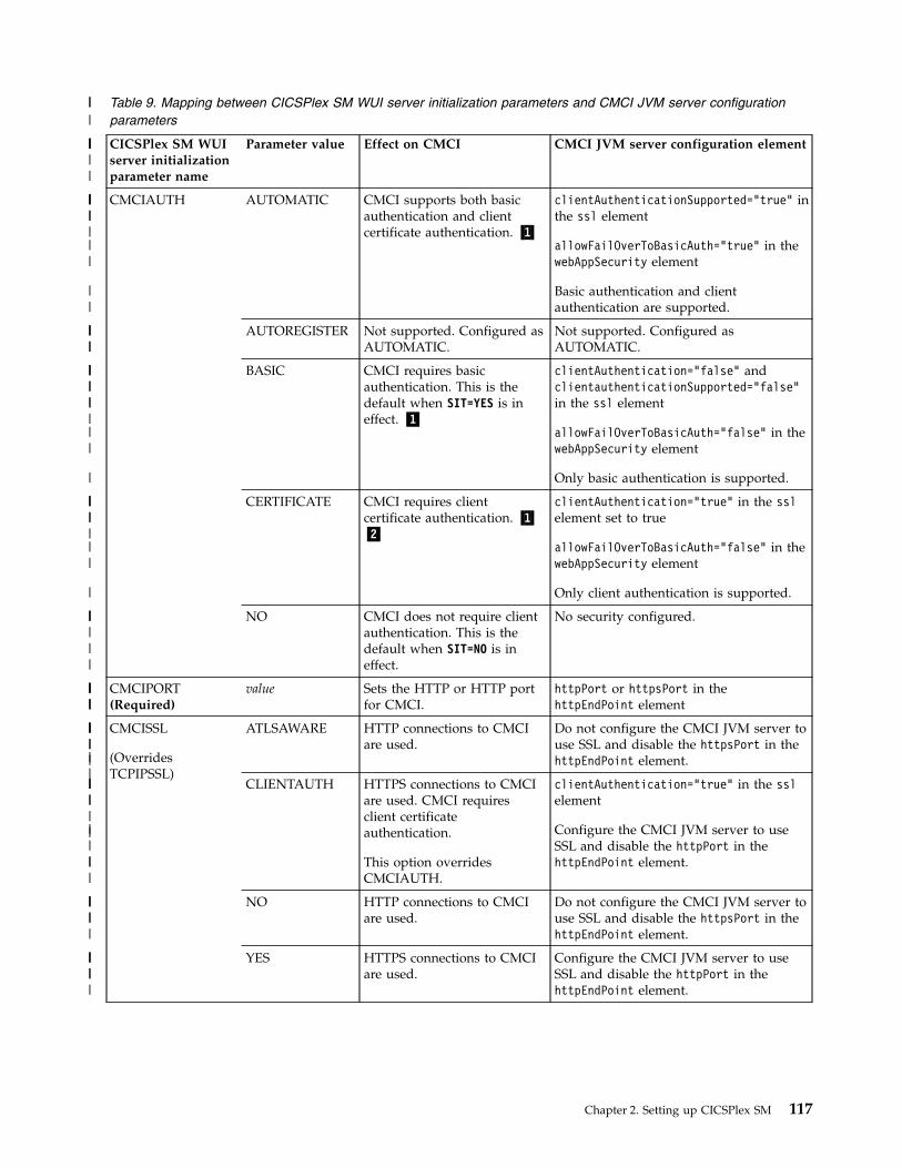
Table 9. Mapping between CICSPlex SM WUI server initialization parameters and CMCI JVM server configurationparameters
CICSPlex SM WUIserver initializationparameter name
Parameter value Effect on CMCI CMCI JVM server configuration element
CMCIAUTH AUTOMATIC CMCI supports both basicauthentication and clientcertificate authentication. ▌1▐
clientAuthenticationSupported="true" inthe ssl element
allowFailOverToBasicAuth="true" in thewebAppSecurity element
Basic authentication and clientauthentication are supported.
AUTOREGISTER Not supported. Configured asAUTOMATIC.
Not supported. Configured asAUTOMATIC.
BASIC CMCI requires basicauthentication. This is thedefault when SIT=YES is ineffect. ▌1▐
clientAuthentication="false" andclientauthenticationSupported="false"in the ssl element
allowFailOverToBasicAuth="false" in thewebAppSecurity element
Only basic authentication is supported.
CERTIFICATE CMCI requires clientcertificate authentication. ▌1▐▌2▐
clientAuthentication="true" in the sslelement set to true
allowFailOverToBasicAuth="false" in thewebAppSecurity element
Only client authentication is supported.
NO CMCI does not require clientauthentication. This is thedefault when SIT=NO is ineffect.
No security configured.
CMCIPORT(Required)
value Sets the HTTP or HTTP portfor CMCI.
httpPort or httpsPort in thehttpEndPoint element
CMCISSL
(OverridesTCPIPSSL)
ATLSAWARE HTTP connections to CMCIare used.
Do not configure the CMCI JVM server touse SSL and disable the httpsPort in thehttpEndPoint element.
CLIENTAUTH HTTPS connections to CMCIare used. CMCI requiresclient certificateauthentication.
This option overridesCMCIAUTH.
clientAuthentication="true" in the sslelement
Configure the CMCI JVM server to useSSL and disable the httpPort in thehttpEndPoint element.
NO HTTP connections to CMCIare used.
Do not configure the CMCI JVM server touse SSL and disable the httpsPort in thehttpEndPoint element.
YES HTTPS connections to CMCIare used.
Configure the CMCI JVM server to useSSL and disable the httpPort in thehttpEndPoint element.
Chapter 2. Setting up CICSPlex SM 117
|||
|||
|||
|||||
||
||
||
|||||
|||||
|||
||
|
||||
||
||
|
|||||
|
|||||||
|
||
||||||
|||||
||
||
|||
||||||
||||||

Table 9. Mapping between CICSPlex SM WUI server initialization parameters and CMCI JVM server configurationparameters (continued)
CICSPlex SM WUIserver initializationparameter name
Parameter value Effect on CMCI CMCI JVM server configuration element
TCPIPADDRESS
(OverridesTCPIPHOSTNAME)
name Allows client connections toCMCI by using only theprovided TCP/IP address.
host in the httpEndPoint element
INADDR_ANY Allows client connections toCMCI by using any TCP/IPaddress associated with theLPAR.
host="*" in the httpEndPoint element
TCPIPHOSTNAME(Required)
name Provides the host name forclient connections to CMCI.
host in the httpEndPoint element
ALL Allows client connections byusing any host nameassociated with the LPAR.
host="*" in the httpEndPoint element
TCPIPHTTPHOST YES|NO Not used by CMCI. Not applicable
TCPIPSSL YES HTTPS connections to CMCIare used.
Configure the CMCI JVM server to useSSL and disable the httpPort in thehttpEndPoint element.
NO HTTP connections to CMCIare used. This is the default.
Do not configure the CMCI JVM server touse SSL and disable the httpsPort in thehttpEndPoint element.
TCPIPSSLCERT name Not used by CMCI. Not used.
Liberty will use the default certificate. ▌3▐
TCPIPSSLCIPHERS cipher_list Provides the list of ciphersavailable to CMCI. ▌4▐
enabledCiphers in the ssl element
Only used when SSL is active. ▌4▐
Note:
1. Valid when SEC=YES is in effect.2. The KEYRING system initialization parameter must be in effect.3. Ensure that a default SSL certificate is configured in Liberty. For more
information, see SSL defaults in Liberty.4. If the list contains any invalid ciphers, CICS removes invalid ciphers and
continues as long as at least one valid cipher remains. If there are no validciphers, access to CMCI will be rejected. Liberty allows invalid ciphers to beconfigured but rejects connections with message Unsupported ciphersuite inthe Liberty logs. In such cases, the following messages help you identify thecause of the problem:
DFHSO0145W indicates that invalid ciphers have been supplied.DFHSO0146I lists the invalid ciphers that were removed by CICS.
Table 10 on page 119 shows how the WUI region system initialization parametersare mapped to the CMCI JVM server configuration parameters and indicates whatadditional configuration is required in the CMCI JVM server.
118 CICS TS for z/OS: CICSPlex SM Concepts and Planning
||
|||
|||
|
||
||||
|
|||||
|
||||||
||||
|
||
||
||
|||||||
||||||
||||
|
|||||
||
|
|
|
||
||||||
|
|
|||

Table 10. Mapping between CICSPlex SM WUI region system initialization parameters and CMCI JVM serverconfiguration parameters
CICSPlex SM WUIregion systeminitializationparameter name
Parameter value Effect on CMCI CMCI JVM server configurationelement
APPLID applid Sets the prefix for CMCIsecurity profiles.
profilePrefix in the safCredentialselement
DFLTUSER userid Sets the CMCIunauthenticated default user.
unauthenticatedUser in thesafCredentials element
Used when security is active.
KEYRING keyring-name Provides the name of theKeyring used for HTTPS orclient certificateauthentication.
location in the keyStore element
Used when SSL or client certification isactive.
MINTLSLEVEL Not used by CMCI. You can configure sslProtocol in thessl element to set the SSL protocol.
NISTSP800131A NOCHECK|CHECK Instructs CMCI to check forconformance to the NISTSP800-131A standard.
Configure Liberty to run inSP800-131a.
SEC NO Disables authentication. Disables Liberty security.
YES Enables basic authenticationin CMCI, unless overriddenby CMCIAUTH.
Enables Liberty security.
Record count warnings in CMCISetting up record count warnings causes a CICS management client interface(CMCI) request to fail if a request is likely to result in the retrieval of anunacceptably large amount of data. You set up record count warnings byspecifying a nonzero value for the DEFAULTWARNCNT initialization parameter duringWUI server configuration when setting up CMCI.
DEFAULTWARNCNT can take an integer value in the range 0 - 99999999. The defaultvalue is 0, meaning that no warnings are issued.
If the warning mechanism determines that the number of records to be returned isgreater than the value of the warning count, the request fails with an HTTP 403response code. Users must issue a new request with different values for theSCOPE, CRITERIA and, in some cases, PARAMETER options to retrieve anyresults. If the returned value is less than or equal to the warning count value, therequest is processed, in the usual way.
Note: In CMCI requests, the options count, index and SUMMONLY can be used tolimit or prevent the display of records. However, these options do not influence thenumber of records requested and have no affect on the record count warningmechanism.
How to allow users to bypass record count warnings
If DEFAULTWARNCNT is set to a nonzero value, a warning count limit is in effect.Users can bypass the warning count limit by using the CMCI URI optionOVERRIDEWARNINGCOUNT in their requests. For the CMCI URI optionOVERRIDEWARNINGCOUNT to take effect, when setting up CMCI, you must set the
Chapter 2. Setting up CICSPlex SM 119
|||
||||
||||
||||||
||||||
|
||||||
|
||
|||||
|||||
||
||||
||||
|
|
||||||
||
||||||
||||
|
||||

RESOURCELIMIT initialization parameter to WARNING during WUI serverconfiguration. If you want to prevent users from bypassing the warning countlimit, set RESOURCELIMIT to FAIL.
When RESOURCELIMIT(WARNING) is in effect, if a request results in the retrievalof an amount of data larger than the warning count limit, a 403 HTTP response isreturned and indicates that the errorInfo attribute override_warning_count_allowedis set to yes. The user can then bypass the warning count limit by using the CMCIURI option OVERRIDEWARNINGCOUNT in the request.
However, when RESOURCELIMIT(FAIL) is in effect, such requests are denied, andin the 403 HTTP response, the errorInfo attribute override_warning_count_allowedis set to no. Issuing a request with the OVERRIDEWARNINGCOUNT option will still resultin the same 403 HTTP response.
Which CMCI resources are applicable
This feature does not apply to all resources. In the CMCI, record count warningsapply only to CMCI requests associated with the following resources:
CMCI Resources
AIMODEL
ATOMSERV
BRFACIL
BUNDLE
BUNDPART
CFDTPOOL
CICSDSA
CICSPAGP
CICSRGN
CICSSTOR
CLCACHE
CMDT
CONNECT
DBCTLSS
DB2CONN
DB2ENTRY
DB2TRN
DOCTEMP
DOMSPOOL
DSNAME
DSPGBL
DSPMODE
DSPPOOL
EJCOBEAN
EJCOSE
EJDJAR
120 CICS TS for z/OS: CICSPlex SM Concepts and Planning
|||
|||||
||||
|
||
||
|
|
|
|
|
|
|
|
|
|
|
|
|
|
|
|
|
|
|
|
|
|
|
|
|
|

CMCI Resources
EJDJBEAN
ENQUEUE
ENQMODEL
EPADAPT
EPADSET
EPAINSET
EVCSDATA
EVCSINFO
EVCSOPT
EVCSPEC
EVNTBIND
EVNTGBL
EXCI
EXITGLUE
EXITTRUE
EXTRATDQ
FEPICONN
FEPINODE
FEPIPOOL
FEPIPROP
FEPITRGT
HOST
HTASK
INDTDQ
INTRATDQ
IPCONN
IPFACIL
JRNLMODL
JRNLNAME
JVM
JVMPOOL
JVMPROF
JVMSERV
LIBDSN
LIBRARY
LOADACT
LOADER
LOCFILE
LOCTRAN
LSRPBUF
LSRPOOL
Chapter 2. Setting up CICSPlex SM 121
|
|
|
|
|
|
|
|
|
|
|
|
|
|
|
|
|
|
|
|
|
|
|
|
|
|
|
|
|
|
|
|
|
|
|
|
|
|
|
|
|
|

CMCI Resources
MASHIST
MODENAME
MONITOR
MQCON
MQCONN
MQINI
MVSESTG
MVSTCB
MVSTCBGL
MVSWLM
OSGIBUND
OSGISERV
PARTNER
PIPELINE
PROCTYP
PROFILE
PROGRAM
RECOVERY
REMFILE
REMTDQ
REMTRAN
REQID
RPLLIST
RQMODEL
RULE
STREAMNM
SYSDUMP
SYSPARM
TASK
TASKASSC
TASKESTG
TASKFILE
TASKRMI
TASKTSQ
TCPIPGBL
TCPIPS
TDQGBL
TERMNL
TRANCLAS
TRANDUMP
TSKSPOLS
122 CICS TS for z/OS: CICSPlex SM Concepts and Planning
|
|
|
|
|
|
|
|
|
|
|
|
|
|
|
|
|
|
|
|
|
|
|
|
|
|
|
|
|
|
|
|
|
|
|
|
|
|
|
|
|
|

CMCI Resources
TSKSPOOL
TSMODEL
TSPOOL
TSQGBL
TSQNAME
TSQSHR
UOW
UOWDSNF
UOWENQ
UOWLINK
URIMAP
URIMPGBL
WEBSERV
WORKREQ
XMLTRANS
Estimating storage requirements for CMCITo avoid possible storage problems when you use the CICS management clientinterface, you must specify appropriate levels of 64-bit (above-the-bar) storage inthe CICS region, and auxiliary storage. Use the z/OS MEMLIMIT parameter to set thelimit for 64-bit storage in your WUI server or CICS region, and the MAXAUXCPSM andMAXAUXTOTL CICSPlex SM system parameters to set auxiliary storage for the CMAS.
About this task
Running CMCI with large workloads can lead to short-on-storage situations on theWUI server and possible CMAS shutdowns caused by running out of auxiliarystorage.
CMCI stores retained results sets for the WUI server in 64-bit storage in the CICSregion, in subpool WU_64 in the GCDSA.
During a CMCI request, the CMAS collects and stores the requested resourcerecords, which are then backed up in auxiliary storage. Running requestsconcurrently through the CMCI multiplies the number of records held by theCMAS with each request.
Procedure1. Calculate the storage requirement for a typical request. Select the resource that
is likely to generate the largest number of records in a request and multiply thenumber of records by the size of each record. See the appropriate table inCICSPlex SM resource tables in Reference to determine the record size.
2. Calculate your total requirements for 64-bit storage for retained result sets.Estimate your expected maximum number of retained result records for asingle request and multiply this figure by your estimate of the storage requiredfor each request. For example, if you can have 100,000 CICS terminals in asingle request, multiply this figure by the size of the resource record asdetermined in step 1.
Chapter 2. Setting up CICSPlex SM 123
|
|
|
|
|
|
|
|
|
|
|
|
|
|
|
||
||||||
|
|||
||
||||
|
||||
||||||

3. If you are setting up CMCI in a CICSPlex SM environment, estimate yourauxiliary storage requirements for your CMAS. Estimate the maximum numberof concurrent requests that you can expect and multiply this figure by yourestimate of the storage required for each request as calculated in step 2. Youcan derive your estimate of concurrent requests from the total number of usersthat you expect to be using CMCI at any one time and how many simultaneousrequests they are likely to make.
4. Consider adding more storage for metadata. CMCI stores all requested resourcerecords for each request for a new retained result. For the initial request of anew resource type, for example, a first request for CICS programs, a smallamount of attribute metadata is also stored. For large requests, the size of theattribute metadata and any other storage used while making the request isnegligible compared to the storage required for records themselves. Consideradding an extra 2% to your final estimate to cover any extra metadata usedinternally by CMCI on the WUI server. This extra metadata is not necessary forthe CMAS calculation.
What to do nextv If CMCI is installed in a CICSplex SM environment, use your estimate of
auxiliary storage to set values for the MAXAUXCPSM and MAXAUXTOTL parameters onthe CMAS associated with your WUI server.
v Use your estimate of the 64-bit storage required for retained result sets to helpdetermine the z/OS MEMLIMIT value for your WUI server, or your CICS region ifyou are running the single server version of CMCI. You must allow for the otherCICS facilities that use 64-bit storage.For information about the MEMLIMIT value for CICS, and instructions to check thevalue of MEMLIMIT that currently applies to the CICS region, see Estimating,checking, and setting MEMLIMIT in Improving performance. For furtherinformation about MEMLIMIT in z/OS, see Limiting the use of private memoryobjects in the z/OS MVS Programming: Extended Addressability Guide.
Defining a client whitelist to CMCI JVM serverYou can use a client whitelist to limit clients that can connect to the CMCI JVMserver. For example, you can limit which levels of CICS Explorer can connect tothe CMCI JVM server.
About this task
The client whitelist is an ASCII file that contains a list of valid User-agent HTTPheaders that are sent by a client such as CICS Explorer.
You use the com.ibm.cics.jvmserver.cmci.user.agent.white.list JVM propertyto specify the location to the whitelist file. If the property is not defined in the JVMprofile of the CMCI JVM server, all clients are accepted.
If a user-agent is not in the file, the request is rejected with HTTP code 403, andmessage DFHSJ1412 is issued. You can specify an alternative response text toreturn to the user by using thecom.ibm.cics.jvmserver.cmci.user.agent.white.list.reject.text JVM property.
Note: The CICS Explorer user-agent encodes the versions of several CICS Explorercomponents and therefore can change when components are updated. With CICSExplorer Version 5.4.0.5 or later, you can discover the user-agent that a runningCICS Explorer installation presents by clicking Help > About > Installation
124 CICS TS for z/OS: CICSPlex SM Concepts and Planning
|||||||
|||||||||
|
|||
||||
|||||
||||
|
||
|||
||||
||||

Details > Configuration. The CMCI User Agent string is listed in theConfiguration tab of the Installation Details dialog box.
Procedure1. Define a client whitelist file.
The file must be saved in the ASCII file encoding. Example:# CICS Explorer User-Agent headerIBM_CICS_Explorer/5.4.0.201705302008 IBM_zOS_Explorer/3.1.0.201706061805 JRE/1.8.0 (Windows 7)
2. Specify the file location as follows:Uncomment the following line in the JVM profile for the CMCI JVM server,EYUCMCIJ.jvmprofile, and specify the file location.
-Dcom.ibm.cics.jvmserver.cmci.user.agent.white.list=/var/userAgentWhiteList
If a user attempts to connect to the CMCI JVM server from a client that is not inthe whitelist, the request is rejected with HTTP code 403 by default. If you want toreturn a custom response text to the user, continue with step 3.3. Optional: In the JVM profile for the CMCI JVM server, EYUCMCIJ.jvmprofile,
add the following line, where response_text is your message to the user:-Dcom.ibm.cics.jvmserver.cmci.user.agent.white.list.reject.text=response_text
Results
Only user-agents that are defined in the whitelist are allowed to connect to CMCI.
Troubleshooting: If no user-agents are allowed access to CMCI, there might be anissue with the client whitelist configuration. For example, the file specified in thecom.ibm.cics.jvmserver.cmci.user.agent.white.list JVM property cannot befound, or the file contains invalid values. In such cases, message DFHSJ1408 isissued.
What to do next
Updating the whitelist
The whitelist values in this file are held in a cache, which by default isrefreshed by Liberty cache file monitoring. Liberty cache file monitoringchecks whether the file has changed every 10 seconds by default.
If you need to update the list, you might want to override the default bysetting the following Java system property in the JVM profile of the CMCIJVM server:-Dcom.ibm.cics.jvmserver.cmci.user.agent.white.list.monitor.interval=20s
Setting up CMCI in a stand-alone CICS regionTo use the CICS management client interface (CMCI) in a stand-alone CICS region(SMSS) without using CICSPlex SM, you must add the SEYUAUTH andSEYULOAD libraries to the startup JCL of your CICS region and then installURIMAP and TCPIPSERVICE resource definitions.
About this task
When CMCI is set up in a CICS region, you can use it to manage CICS operationalresources and CICS definitional resources. See CICS management client interfaceresource names in Reference for a complete list of the operational resources thatthe interface can manage.
Chapter 2. Setting up CICSPlex SM 125
||
|
|
|
||
|
||
|
|||
||
|
|
|
|||||
|
|
|||
|||
|
|

Sample resource definitions are provided for setting up the CICS managementclient interface. DFH$WUUR is a sample URIMAP definition and DFH$WUTC is asample TCPIPSERVICE definition. The samples are included in the CICS systemdefinition file (CSD) in group DFH$WU. You can install these resources as theyare, or more typically you can copy and modify them to tailor them for yourenvironment. However, you must always specify the URIMAP path asCICSSystemManagement/*. This procedure does not activate security on the interface.For more information about security settings, see “Setting up CMCI in a CICSregion with active security” on page 128.
If security is not active, messages that are produced by auditing systemprogramming interface commands contain the default user ID of the region.
Use the following procedure to set up the CICS management client interface byusing the samples provided.
Procedure1. Change your CICS startup JCL:
a. Add the hlq.CPSM.SEYUAUTH library to the STEPLIB concatenation, wherehlq is your high-level qualifier; for example CICSTS55
b. Add the hlq.CPSM.SEYULOAD library to the DFHRPL concatenation, wherehlq is your high-level qualifier; for example CICSTS55
These libraries must be at the same CICS TS level as those for CICS; that is, thesame as the CICS hlq.CICS.SDFHAUTH and CICS hlq.CICS.SDFHLOADlibraries in the STEPLIB concatenation.
2. Ensure that the system initialization parameter CPSMCONN is set to NO foryour CICS region. CPSMCONN must be set to NO for CICS Explorer toconnect to a CMCI standalone region.
3. Ensure that the RDO group DFHFEPI is being installed in a list that is includedin the group list (GRPLIST) at CICS startup. The DFHFEPI group is included inthe default CICS startup list DFHLIST. The group contains resources that arerequired by CMCI.
4. Start your CICS region.5. Install the sample URIMAP definition, DFH$WUUR. This sample URI map
uses transaction CWWU and calls program DFHWBA to analyze the CICS webrequest. DFH$WUUR includes the following attribute values:
Attribute name Attribute value
Description Sample System Management Interface URImap
Group DFH$WU
Host *
Path CICSSystemManagement/*
Port No
Program DFHWUIPG
Scheme HTTP
Status Enabled
TCP/IP service name DFH$WUTC
Transaction CWWU
URI map DFH$WUUR
126 CICS TS for z/OS: CICSPlex SM Concepts and Planning

Attribute name Attribute value
Usage Server
Other attributes in the sample definition retain their default values.
Note: The TCP/IP service name must match your TCPIPSERVICE definition. Ifyou use a TCPIPSERVICE definition with a name other than DFH$WUTC,ensure that you rename the TCP/IP service name in the URIMAP definitionaccordingly.
6. Copy and rename the sample TCPIPSERVICE definition, DFH$WUTC andchange the port number to a unique value. DFH$WUTC includes the followingattribute values:
Attribute name Attribute value
Authentication level No
CICS transaction ID CWXN
Description Sample System Management InterfaceTCPIP service
Group DFH$WU
Host Any
Port 1490
Protocol HTTP
Queue backlog limit 0
SSL No
Status Open
TCP/IP service name DFH$WUTC
Timeout for socket close No
User-replaceable module name DFHWBAAX
Other attributes in the sample definition can retain their default values.7. Install the TCPIPSERVICE definition.
Tips:
v You must define the following transactions to RACF, or an equivalentexternal security manager, and ensure that CMCI users are authorized toaccess the transactions: CODB, COD0, COD1, COD2, COSH, COLU, CWWU,and CWXN.
v Ensure that the DFHCNV table used by CICS contains a DFHWBUD entry.v If you use your own version of the DFHCNV source module, you must
assemble and link-edit it using the new macros or ensure that you includethe necessary code pages.
What to do next
Use CICS Explorer or a browser to check that your setup works correctly.
If necessary, you can use the following checks:
Chapter 2. Setting up CICSPlex SM 127

1. Check that the TCPIPSERVICE is OPEN and URIMAP is ENABLED on thestand-alone region. Confirm the port and that the URIMAP references theTCPIPSERVICE with the new name and not the old DFH$WUTC resource thatyou copied.
2. Try to access the URL by using the following request in your browser. If thebrowser returns a result, your setup is working as expected. The CMCIURIMAP responds only to requests for URLs that begin as follows:http://hostname:port/CICSSystemManagement/CICSTask/
3. Check for any SMSS related messages on the region job log, for example:EYUXL0022I xxxxxxxx SMSS Phase I initialization completeEYUXL0007I xxxxxPhase II initialization completeEYUNL0099I xxxxxxxx SMSS LRT initialization complete
4. Check for any installation errors in both the job log and the MSGUSR log.5. Try to connect CICS Explorer to the CMCI port to check whether that
connection works.
Setting up CMCI in a CICS region with active securityTo set up CMCI with active security in a standalone CICS region (SMSS), you mustchange the settings in the sample definitions. Copy and rename the samples, thenchange the TCPIPSERVICE definition to enable security, and update the URIMAPdefinition to refer to the updated TCPIPSERVICE definition.
About this task
You can choose to use either HTTP basic authentication, or for a higher level ofsecurity, secure sockets layer (SSL) authentication. See Security for CICS websupport for information about the security measures you can use to protect accessto the interface.
If security is active, messages produced by auditing system programming interfacecommands contain the user ID used to log on to CICS Explorer.
To set up the CICS management client interface with active security using thesample definitions, use the following procedure.
Procedure1. Copy and rename the sample TCPIPSERVICE definition, DFH$WUTC, and the
sample URIMAP definition, DFH$WUUR. These samples are included in theCICS system definition file (CSD) in group DFH$WU.
2. Change the TCPIPSERVICE definition to incorporate the security features thatyou want. See Creating TCPIPSERVICE resource definitions for CICS websupport for guidance about creating TCPIPSERVICE definitions that includesecurity for web clients.
3. Change the TCPIPSERVICE attribute in your URIMAP definition to refer toyour renamed TCPIPSERVICE. You can also change the SCHEME attributefrom HTTP to HTTPS, but this is not essential because this change is madeautomatically to an installed URIMAP if its associated TCPIPSERVICE hassecurity enabled.
4. Install the definitions into your CICS region. See Ways of defining CICSresources for an explanation of the methods that you can use to install theseresource definitions.
128 CICS TS for z/OS: CICSPlex SM Concepts and Planning
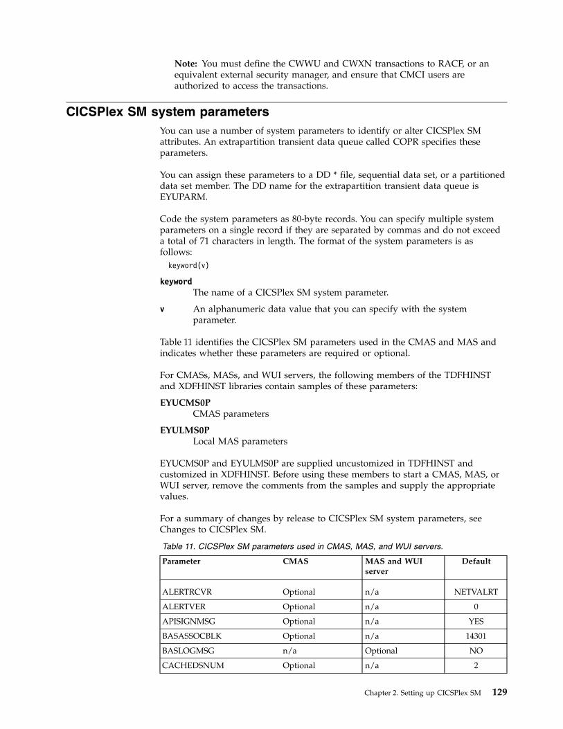
Note: You must define the CWWU and CWXN transactions to RACF, or anequivalent external security manager, and ensure that CMCI users areauthorized to access the transactions.
CICSPlex SM system parametersYou can use a number of system parameters to identify or alter CICSPlex SMattributes. An extrapartition transient data queue called COPR specifies theseparameters.
You can assign these parameters to a DD * file, sequential data set, or a partitioneddata set member. The DD name for the extrapartition transient data queue isEYUPARM.
Code the system parameters as 80-byte records. You can specify multiple systemparameters on a single record if they are separated by commas and do not exceeda total of 71 characters in length. The format of the system parameters is asfollows:
keyword(v)
keywordThe name of a CICSPlex SM system parameter.
v An alphanumeric data value that you can specify with the systemparameter.
Table 11 identifies the CICSPlex SM parameters used in the CMAS and MAS andindicates whether these parameters are required or optional.
For CMASs, MASs, and WUI servers, the following members of the TDFHINSTand XDFHINST libraries contain samples of these parameters:
EYUCMS0PCMAS parameters
EYULMS0PLocal MAS parameters
EYUCMS0P and EYULMS0P are supplied uncustomized in TDFHINST andcustomized in XDFHINST. Before using these members to start a CMAS, MAS, orWUI server, remove the comments from the samples and supply the appropriatevalues.
For a summary of changes by release to CICSPlex SM system parameters, seeChanges to CICSPlex SM.
Table 11. CICSPlex SM parameters used in CMAS, MAS, and WUI servers.
Parameter CMAS MAS and WUIserver
Default
ALERTRCVR Optional n/a NETVALRT
ALERTVER Optional n/a 0
APISIGNMSG Optional n/a YES
BASASSOCBLK Optional n/a 14301
BASLOGMSG n/a Optional NO
CACHEDSNUM Optional n/a 2
Chapter 2. Setting up CICSPlex SM 129

Table 11. CICSPlex SM parameters used in CMAS, MAS, and WUI servers. (continued)
Parameter CMAS MAS and WUIserver
Default
CICSPLEX n/a Required
CMASSYSID n/a Optional See description
CMTCMLNKACQ Optional n/a RECONN
COHTTASKPRI n/a Optional 200
COIRTASKPRI n/a Optional 200
COMMTSBLOCKS Optional Optional 128 (MAS)
512 (CMAS)
HISTORYONLY n/a Optional NO
HISTRECSMSG n/a Optional 0
HISTSECS n/a Optional 30
JRNLDEFCH Optional n/a NO
JRNLOPACT Optional n/a NO
JRNLRTAEV Optional n/a NO
MASALTLRTCNT n/a Optional 0
MASALTLRTPRI n/a Optional 255
MASALTLRTTIM n/a Optional 10
MASINITTIME n/a Optional 10
MASPLTWAIT n/a Optional NO
MASTASKPROT Optional n/a NO
MAXAUXCPSM Optional n/a 50
MAXAUXTOTL Optional n/a 70
MAXHISTRECS n/a Optional 1
MSGBUCKETS n/a Optional 1024
NAME Optional Optional
RESSTATUS Optional n/a NOTIFY
SEC Optional n/a NO
SECLOGMSG Optional n/a NO
SECRPTLVL Optional n/a RESPONSE
SECTIMEOUT Optional n/a 30
SPOOLCLASS Optional Optional P
STALLASYTSK n/a Optional 4
STALLASYCNT n/a Optional 4
STALLCONTSK n/a Optional 2
STALLCONCNT n/a Optional 3
STALLDBCTSK n/a Optional 4
STALLDBCCNT n/a Optional 4
STALLDB2TSK n/a Optional 4
STALLDB2CNT n/a Optional 4
STALLDLITSK n/a Optional 4
130 CICS TS for z/OS: CICSPlex SM Concepts and Planning

Table 11. CICSPlex SM parameters used in CMAS, MAS, and WUI servers. (continued)
Parameter CMAS MAS and WUIserver
Default
STALLDLICNT n/a Optional 4
STALLDSPTSK n/a Optional 4
STALLDSPCNT n/a Optional 2
STALLEJBTSK n/a Optional 2
STALLEJBCNT n/a Optional 3
STALLENQTSK n/a Optional 4
STALLENQCNT n/a Optional 4
STALLFLETSK n/a Optional 3
STALLFLECNT n/a Optional 4
STALLILKTSK n/a Optional 2
STALLILKCNT n/a Optional 3
STALLIPCTSK n/a Optional 2
STALLIPCCNT n/a Optional 3
STALLLCKTSK n/a Optional 4
STALLLCKCNT n/a Optional 4
STALLLGRTSK n/a Optional 2
STALLLGRCNT n/a Optional 3
STALLITVTSK n/a Optional 0
STALLITVCNT n/a Optional 0
STALLJNLTSK n/a Optional 1
STALLJNLCNT n/a Optional 3
STALLMQSTSK n/a Optional 2
STALLMQSCNT n/a Optional 3
STALLPGMTSK n/a Optional 2
STALLPGMCNT n/a Optional 4
STALLRMITSK n/a Optional 2
STALLRMICNT n/a Optional 3
STALLSESTSK n/a Optional 2
STALLSESCNT n/a Optional 3
STALLSOCTSK n/a Optional 2
STALLSOCCNT n/a Optional 3
STALLSTGTSK n/a Optional 1
STALLSTGCNT n/a Optional 2
STALLTDQTSK n/a Optional 3
STALLTDQCNT n/a Optional 4
STALLTRMTSK n/a Optional 0
STALLTRMCNT n/a Optional 0
STALLTSKTSK n/a Optional 0
STALLTSKCNT n/a Optional 0
Chapter 2. Setting up CICSPlex SM 131

Table 11. CICSPlex SM parameters used in CMAS, MAS, and WUI servers. (continued)
Parameter CMAS MAS and WUIserver
Default
STALLTSQTSK n/a Optional 3
STALLTSQCNT n/a Optional 4
STALLUSRTSK n/a Optional 0
STALLUSRCNT n/a Optional 0
STALLWEBTSK n/a Optional 2
STALLWEBCNT n/a Optional 3
STALLXMGTSK n/a Optional 4
STALLXMGCNT n/a Optional 2
STALLXRFTSK n/a Optional 1
STALLXRFCNT n/a Optional 2
SUPPRESSCMF n/a Optional NO
TOBATCHREQ Optional n/a 0
TOONLINEREQ Optional n/a 0
TOPOLLINT Optional n/a 300
WLMLCUSH n/a Optional 20
Note: Support for the WLMLOADCOUNT and WLMLOADTHRSH EYUPARMvalues is discontinued in CICS TS for z/OS, Version 4.1.
ALERTRCVR(NETVALRT | name)Identifies the 1- 8-character name of the NetView Alert Receiver to be usedby the CMAS if the CMAS sends NetView Generic Alerts to NetView.
ALERTVER( 0 | 1 )Identifies the version of the CICSPlex SM generic alert record that theCMAS sends to NetView. See Generic alert and resolution structures fordetails about the generic alert Records that CICSPlex SM sends to NetView.
ALERTVER is relevant only for a CMAS that i named in an ACTNDEF asa CMAS that sends generic alerts to NetView.
APISIGNMSG(YES | NO)Indicates whether the successful signon and signoff message, EYUXD0807I,is issued when a CICSPlex SM API user connects to, or disconnects(TERMINATE) from, the CICSPlex SM API.
BASASSOCBLK(value | 14301)Specifies the number of BAS association blocks that can be acquired from asingle association element. The default EYUPARM value creates anassociation segment size requiring approximately 1.2 MB of storage. If youspecify the maximum value of 114597 blocks-per-segment is specified, thenthe resultant segment size is just over 8 MB.
BASLOGMSG(YES | NO)Indicates whether CICS resources defined using BAS must have theirdefinitions logged to the CSDL Transient Data Queue of the MAS whenthey are installed.
If the CICS version used by the MAS does not support the LOGMESSAGEoption of the EXEC CICS CREATE command, BASLOGMSG has no effect.
132 CICS TS for z/OS: CICSPlex SM Concepts and Planning

CACHEDSNUM(value | 2)
Specifies the number of data spaces that this CMAS creates for eachCICSPlex SM component. At least 1MB is allocated in each data cachewhen the data space is created. The value must be in the range 1 to 9.
You can change this parameter only on a CPSM CMAS cold start.Normally, do not change this parameter unless advised to do so by IBMSupport.
CICSPLEX(name)Identifies the 1- to 8-character name of the CICSplex to which the localMAS is to be associated.
The name of a CICSplex must not be the same as the name of a CMAS, aCICS system, or a CICS system group.
CMASSYSID(name)Identifies the 1- to 4-character name of the CMAS to which a MAS is to beattached. If a MAS specifies a CMASSYSID and the CMAS is active butdoes not manage the CICSplex, the MAS waits until the specified CMAS ismanaging the CICSplex before it joins the CICSplex.
You can also use this parameter when a local MAS is to attach to a specificCMAS in the same MVS image.
Note: This parameter is optional. However; for a specific release ofCICSPlex SM, if you do not specify a value for the CMASSYSID parameterand you have multiple CMASs on an MVS system, a local MAS willconnect to the last CMAS initialized on the MVS system that manages theCICSplex specified by the CICSPLEX parameter.
CMTCMLNKACQ(ALWAYS | RECONN)Specifies whether you want the CMAS to attempt to reacquire LU6.2CMAS to CMAS links (CMTCMLNKs) if the initial acquire attempt madeby CICS fails. The initial acquire attempt is made by CICS when a CMASis started, a z/OS Communications Server ACB is opened, or a CMAS toCMAS definition (CMTCMDEF) is installed. If the initial acquire attemptfails, CICSPlex SM network surveillance might attempt to re-acquire theLU6.2 CMAS to CMAS links depending on the value of CMTCMLNKACQ:v If CMTCMLNKACQ is set to ALWAYS, the CMAS attempts to acquire
CMTCMLNKs, independent of whether the links were established in thecurrent CMAS run.
v If CMTCMLNKACQ is set to RECONN, the CMAS attempts tore-acquire CMTCMLNKs only where CMTCMLNKs were established inthe current CMAS run.
If the CMTCMLNKs were not acquired in the current CMAS run and theinitial acquire attempts fail, CMTCMLNK must manually be acquired.
Depending on the CMTCMLNKACQ option that you are using, repeatedfailed acquire attempts can produce messages DFHZC3437, DFHZC3462and DFHZC2405 and z/OS Communications Server IST663 and IST664.
CMTCMLNKACQ can be dynamically changed in a CMAS using theCOD0 SET command.
COHTTASKPRI(value | 200)Specifies the task priority of COHT, in the range 0 - 255. COHT is aCICSPlex SM system task that you can use to process evaluationdefinitions, EVALDEFs, independent of the MAS. COHT is invoked in a
Chapter 2. Setting up CICSPlex SM 133

MAS when an API or a Web User Interface query for completed taskhistory records (HTASK records) is directed to the MAS. Use thisparameter to tune the priority of HTASK requests so that aresource-intensive query does not affect the performance of other tasks inthe MAS.
COIRTASKPRI(value | 200)Specifies the task priority of COIR, in the range 0 - 255. COIR is aCICSPlex SM system task that you can use to process evaluationdefinitions, EVALDEFs, independent of the MAS.
For each EVALDEF that requests a separate task, an instance of COIR isstarted at the specified priority. If you specify a priority of 0, no separateCOIR system tasks are started; all EVALDEFs are processed by the MASlong running task (LRT).
COMMTSBLOCKS((value | 512/128)Specifies the number of sets of control blocks allocated at CMAS or MASstartup for CICSPlex SM Communications Transport Services. These controlblocks are used when data must be shipped between a CMAS or MAS andother CMASs or MASs.
The default and minimum values for this parameter are 512 in a CMASand 128 in a MAS. The maximum value is 8192 in either a CMAS or MAS.
Each set requires 1204 bytes of storage allocated in ESDSA in the CMAS orMAS. If the defaults are used, this amount of total storage is allocated:CMAS: 512 * 1204 = 616,448 bytesMAS: 128 * 1204 = 154,112 bytes
If the maximum value is specified, this amount of total storage is allocated:CMAS: 8192 * 1204 = 9,863,168 bytesMAS: 8192 * 1204 = 9,863,168 bytes
If a shortage occurs while running a CMAS or MAS, message EYUCT0105Eis issued. At termination of the CMAS or MAS, message EYUCT0106W isissued. The later message includes a value equal to the highest concurrentshortage of sets (high-water mark). Increase the COMMTSBLOCKSparameter for the CMAS or MAS by at least the amount specified by theEYUCT0106W message before restarting the CMAS or MAS.
HISTORYONLY( YES | NO)Specifies whether history data is collected without collecting normalCICSPlex SM monitoring data as well. For example, if MLOCTRAN andMREMTRAN data is not required set HISTORYONLY(YES) to prevent thisdata from being collected.
HISTRECSMSG( value | 0)Specifies that message EYUNL0179I 'Task History Recorder data setEYUHISTx has accrued nnnn records' is produced each time 'value'thousand records are written to the history data sets. The maximumallowed value is 1000 which specifies that a message is produced everytime 1 million records are written to the history data sets.
The message is an aid to determining the optimum size of the history datasets. A value of 0 means that no EYUNL0179I messages are to beproduced.
HISTSECS( value | 30)Specifies the number of seconds to use as the default when API or Web
134 CICS TS for z/OS: CICSPlex SM Concepts and Planning

User Interface users specify a parameter of RECENT(HISTSECS) whenrequesting completed task (HTASK) resource table records. The maximumallowed value is 86400 seconds (24 hours).
JRNLDEFCH(YES | NO)Causes a journal record to be written for each data repository add, delete,and update operation.
JRNLOPACT(YES | NO)Causes a journal record to be written for each successful action commandissued against a MAS or CMAS.
JRNLRTAEV(YES | NO)Causes a journal record to be written each time a real-time analysis (RTA)event is generated.
MASALTLRTCNT(0 - 5 | 0)Indicates the number of alternate long-running system tasks (CONA)started in the MAS during MAS agent initialization. These system tasksremain active until the MAS agent stops or goes into restart mode, andhandle all API, WUI, or RTA requests normally handled by the CONLsystem task, allowing the CONL system task to perform other processingin the MAS. At any time, only one of the CONA system tasks processesrequests. If the CONA system task that is currently processing requestsbecomes busy (as determined by the value of the MASALTLRTTIMEYUPARM), subsequent requests are directed to another CONA systemtask.
If you specify zero (0), no CONA system tasks are started and the CONLsystem task services the API, WUI or RTA requests that are normallydirected to the long running system task. Specifying different values forMASALTLRTCNT for multiple WLM target regions cause an unevendistribution of transactions to those regions because of differinglong-running task counts.
MASALTLRTPRI(0 - 255 | 255)Specifies the priority given to the CONA transaction for running thecurrent MAS. If you specify this value as less than 255 you mightadversely affect the response time of API and WUI users and stop RTAEVENTs from being created or resolved in a timely manner.
MASALTLRTTIM(1 - 3600 | 10)Specifies the amount of time in seconds for which a CONA task can bebusy before subsequent requests are directed to another active CONA task.
MASINITTIME(value | 10)Specifies the number of minutes, from 5 to 59, that CICSPlex SM waits forthe MAS to initialize.v If you specify MASPLTWAIT(YES), the MASINITTIME value is the
maximum length of time that PLT processing can be suspended for MASinitialization. (By suspending PLT processing, the chance of completingMAS initialization in a specified time is increased, because you areasking for less work to be done in a given time interval and therebyreducing the scope for contention during that time).
v If you specify MASPLTWAIT(NO), the MASINITTIME value is themaximum length of time that can elapse before MAS initialization ishalted if it does not complete.
MASPLTWAIT(YES | NO)
Chapter 2. Setting up CICSPlex SM 135
Indicates whether CICSPlex SM suspends all PLT processing until the MASis fully initialized and connected to the CMAS.v When you specify MASPLTWAIT(YES), no CICS applications can be
started and no users can sign on to the system until CICSPlex SMcompletes the installation of resources and resumes PLT processing.
v If CICSPlex SM does complete the installation of resources and resumePLT processing in the time interval specified by MASINITTIME, messageEYUTS0003I is issued.
v If it does not complete in the time interval specified by MASINITTIME,one of two messages will be issued:– EYUNL0090W is issued when MAS initialization is halted and PLT
processing resumes to allow the region to function as a CICS regionwithout CICSPlex SM control.
– EYUXL0090W is issued when MAS initialization is halted and PLTprocessing resumes to allow the region to function as a CICS regionwithout CICSPlex SM control, but the MAS agent continues to waitfor the CICSplex to be registered with the ESSS subsystem by astarting CMAS. When a CMAS registers the CICSplex, MAS agentinitialization will continue.
v MAS initialization can be retried by entering the COLM transactionmanually.
v When you specify MASPLTWAIT(NO), CICSPlex SM still observes theMASINITTIME value waiting for the MAS agent to complete thetopology connect.
v If CICSPlex SM does not complete the topology connect in the timeinterval specified by MASINITTIME or its default value, messageEYUNL0090W is issued, the MAS initialization is halted, and the PLTprocessing resumes to allow the region to function as a CICS regionwithout CICSPlex SM control.
v MAS initialization can be retried by entering the COLM transactionmanually.
If you are including a CICS system in a platform, or if you are usingBusiness Application Services (BAS) to automatically install resources atCICS system initialization, specify MASPLTWAIT(YES) for that system.MASPLTWAIT(YES) is required to automatically install resources for anapplication or platform, or BAS resources, when the CICS region isinitialized.
If you are using Business Application Services (BAS) to automaticallyinstall a Db2 connection, and you want the connection to be activatedduring CICS startup, see “Activating Db2 and IBM MQ connections duringCICS startup” on page 77.
MASTASKPROT (YES | NO)Controls whether the CICSPlex SM API, Web User Interface (WUI), andCICS Management Client Interface (CMCI) are allowed to perform actionsor set attribute values forCICSPlex SM MAS agent system tasks withtransaction IDs COIE, COI0, CONA, or CONL.
Note: Beginning with CICS TS Version 5.4, CICSPlex SM MAS agent tasksthat execute in a MAS that is at CICS TS Version 5.4 cannot be terminatedwith FORCEPURGE. If the MAS is at a release level earlier than CICS TSVersion 5.4, these tasks can be terminated with FORCEPURGE.
136 CICS TS for z/OS: CICSPlex SM Concepts and Planning

v If you specify MASTASKPROT(NO), the default, users of the CICSPlexSM API, WUI, and CMCI are allowed to FORCEPURGE or modifyattribute values for CICSPlex SM MAS agent tasks.
v If you specify MASTASKPROT(YES), CICSPlex SM validates thetransaction ID of all tasks before allowing actions to be performed, orattribute values to be modified for active tasks. If the transaction IDindicates that the task runs as part of the CICSPlex SM MAS agent, therequest is not processed, and a CICS response is set as follows:– RESP = TASKIDERR– RESP2 = 2 (The task is protected by CICS and is not eligible for
modification with this command.)The function code (EIBFN) is null, to indicate that the response issimulated and not set by the CICS SPI.
MAXAUXCPSM(value | 50)Specifies the percentage of total auxiliary storage that can be committed toeach CMAS, in the range of 0 to 99. A value of 0 stops CICSPlex SM fromchecking the amount of space used.
Important: Setting a value of 0 might result in a shortage of auxiliarystorage, requiring an IPL of the MVS system.
Each CMAS requires 24,160 4 KB pages (94 MB) of cache storage atinitialization. If a request for additional cache storage would cause theCMAS to exceed the MAXAUXCPSM threshold, an SDUMP is taken andthe CMAS is terminated. If the threshold is exceeded during CMASinitialization, the CMAS was unable to acquire the initial allocations for allrequired component data cache areas. Either increase the value ofMAXAUXCPSM, or increase the total amount of auxiliary storage byadding or expanding external page data sets. If this threshold is reachedduring an attempt to create or extend a data cache after CMASinitialization has completed, the automatic restart mechanism (ARM) isinvoked to attempt to restart the CMAS.
MAXAUXTOTL(value | 70)Specifies the maximum total auxiliary storage use at which the CMASallows a request for additional cache storage to be made, in the range of 0to 99. A value of 0 stops CICSPlex SM from checking the amount of spaceused.
Important: Setting a value of 0 might result in a shortage of auxiliarystorage, requiring an IPL of the MVS system.
Setting a nonzero value for MAXAUXTOTL prevents the CMAS fromrequesting an amount of cache storage that would cause the MVS systemto enter a state of auxiliary storage shortage. If a request for additionalcache storage causes the CMAS to exceed this threshold, an SDUMP istaken and the CMAS is terminated. This parameter can cause a CMAS toshut down even though the CMAS is not the largest user of auxiliarystorage. If such a shutdown occurs during CMAS initialization, the CMASwas unable to acquire the initial allocations for all required componentdata cache areas. You must increase the total amount of auxiliary storageavailable by adding or expanding external page data sets. If this thresholdis reached during an attempt to create or extend a data cache after CMASinitialization has completed, the automatic restart mechanism (ARM) isinvoked to attempt to restart the CMAS.
Chapter 2. Setting up CICSPlex SM 137

MAXHISTRECS( value | 1)Specifies a value in thousands, in the range 1 to 50. This value is a limit onthe number of records returned on a completed task query from the MAS.You can limit the amount of data in a request for completed task (HTASK)resource table records. When this limit is reached, the CICSPlex SM APIGET request receives a WARNING response and MAXRECORDS reason.
MSGBUCKETS(value | 1024)Specifies a value in the range 1 - 32768. This value specifies the number ofbuffers to be allocated for Topology data collection in the MAS. Each bufferis 64 bytes long. The buffer pool, allocated in the MAS cache data space, isused by CICSPlex SM XMEOUT and XRSINDI global user exits and by theMAS Heartbeat task. The number of buffers must equal or exceed the totalnumber of connections, DSNAMEs, GLUEs, TRUEs, and FEPI connectionsdefined in the MAS. If the number of buffers is not sufficient for theTopology mapped resources in the MAS, a trace record with debug textXDATLOST is written at every other heartbeat interval when MASTopology resource data is collected. Without sufficient buffers, resourcesare missing from Topology Resource Maps for the MAS in all CMASes inthe CICSplex, and query or action requests entered from the WUI or APIfor specific resources can fail because the target resources are not known toTopology.
NAME(name)Identifies the 1- to 8-character name of the CMAS or local MAS that is tobe started. If you do not specify this parameter, the default is the z/OSCommunications Server application ID.
RESSTATUS(NOTIFY | MSG | CONMSG)Indicates how the CMAS is to respond when a CICS resource that is beingreported to the resource status facility has a change in operational state:
NOTIFYIssues event notifications in the form of ERESSTAT resource tablerecords.
You can monitor these event notifications by using the LISTENcommand of the CICSPlex SM API. For more information, seeLISTEN command.
MSG Writes external messages to EYULOG.
If you specify MSG, event notifications are produced in addition tothe messages.
CONMSGWrites external messages to the job log, console, and EYULOG.
If you specify CONMSG, event notifications are produced inaddition to the messages. Use this option with care. It can causemany messages to be sent to the console.
SEC(YES | NO)For a CMAS, indicates whether the CMAS is to perform security checkingof CICSPlex SM requests directed to the CICS systems it manages.
If you specify NO, all security-related parameters are ignored.
If a CMAS manages any CICS regions that are running with security active(SEC=YES specified as a system initialization parameter), the CMAS mustinclude SEC(YES) in EYUPARM. If you do not activate CICSPlex SMsecurity in the CMAS, a connection cannot be established to a CICS system
138 CICS TS for z/OS: CICSPlex SM Concepts and Planning

that specifies SEC=YES. If a connection is attempted, the followingmessage is issued to the console, the CMAS job log, and the CMASEYULOG:
EYUCR0007E Security mismatch between CMAS cmasname and MAS masname. Connection terminating.
If a CMAS that is started with SEC(NO) connects directly or indirectly to aCMAS started with SEC(YES), any request sent to the SEC(YES) CMASfails.v If the request originates from the CICSPlex SM API connected to the
SEC(NO) CMAS, the API request receives: RESPONSE 1031 NOTPERMITREASON 1345 USRID
v If the request originates from the CICSPlex SM Web User Interfaceserver connected to a SEC(NO) CMAS, the Web browser receives themessage EYUVC1220E
SECLOGMSG(NO | YES | ALL)Controls whether CICSPlex SM issues message EYUCR0009I to the CMASEYULOG to record security failures.
When you specify NO, the default, message EYUCR0009I is not issued.
Specify YES, or ALL, to cause message EYUCR0009I to be issued.
SECLOGMSG(YES) can be useful if the External Security Manager (ESM)does not issue messages when it cannot make a decision or when a failureoccurs.
When you specify SECLOGMSG(YES), EYUCR0009I is issued only forrequests that are to be logged to the ESM.
SECLOGMSG(ALL) causes EYUCR0009I to be issued even when the ESMpermits access to the resource. The ALL operand can produce manyEYUCR0009I messages and must normally be used only under thedirection of IBM Support.
You can change SECLOGMSG dynamically in a CMAS with the COD0 SETcommand.
SECRPTLVL (NONE | RESPONSE | DETAIL)Controls the level of detail available to a client API task when a responseof NOTPERMIT with reason USRID is returned by a request.
When you specify NONE, all indications of a security validation exceptionare suppressed. A response of OK or NODATA, as appropriate, is returnedto the client API task.
Specifying the default, RESPONSE, causes the original API response ofNOTPERMIT and reason of USRID to be returned to the client task.
Specifying DETAIL causes a result set of MASQRYER resources to be built,identifying the regions in which the requesting user was denied access to aresource. MASQRYER resources can be retrieved by running a FETCHcommand, passing the QUERYERROR parameter.
Note: The SECRPTLVL parameter controls the response from the CMASin which it is processed even though the API request might haveoriginated in a different CMAS. Thus a CMAS which manages MASescontaining sensitive resources can be started with SECRPTLVL(NONE),while other CMASes managing MASes with lower sensitivity can bestarted with SECRPTLVL(RESPONSE) or SECRPTLVL(DETAIL).
Chapter 2. Setting up CICSPlex SM 139

SECTIMEOUT(value | 30)Specifies the time in minutes, in the range of 1 through 1440 (1 day), thatidle user IDs are to remain signed on in the CMAS before being consideredfor timeout.
You can also use this value to control how often the CMAS checks for idleusers to timeout. For example, with the default value of 30, the CMASchecks every 30 minutes for users who have not used the CMAS for 30minutes. However, because the times are not synchronized the user IDmight not be timed out for up to double the SECTIMEOUT value. Setting alow value increases the number of calls to the External Security Manager(ESM). Setting a high value means that users might have to wait a longtime before automatically picking up security changes that affect the userID (for example, adding the user to a new group).
You can use the CMAS or CMASLIST PURGE request, available from theAPI and WUI, to force a CMAS to check for users to time out immediately.
You can use the CMAS or CMASLIST RESET USERID request, availablefrom the API and WUI, to force the CMAS to rebuild the user's securityinformation the next time it is used. This request is used after adding orremoving a user ID to or from a group, and the user does not want to waitto be timed out to pick up the change.
SPOOLCLASS(class | P)Specifies a SYSOUT class value, from A to Z or 0 to 9, that identifies whereCICSPlex SM spool output is to be sent.
Spool output can be generated by these CICSPlex SM functions:v The online utility transaction COLUv The PRINT and CAPTURE commands of the interactive debugging
transaction COD0
STALLxxxCNTxxx represents a CICSPlex SM suspend class. The values for xxx are shownin Table 12 on page 141.
Identifies the number of consecutive occurrences of an entry in thesuspend class required for CICSPlex SM to report a STALL. The value canbe 0 - 999. Use 0 to indicate that STALL detection for the xxx suspend classis not active. The default value for each task is shown in Table 11 on page129.
Note:
v From CICS Transaction Server for z/OS V5.4, tasks that are internallyinitiated in a MAS by CICSPlex SM no longer execute as user tasks. As aresult, these tasks no longer qualify for STALL detection.
v From CICS Transaction Server for z/OS V5.4, MQSERIES suspends onthe GETWAIT resource are not applicable for STALL detection.
STALLxxxTSKxxx represents a CICSPlex SM suspend class. The values for xxx are shownin Table 12 on page 141.
Identify the minimum number of concurrent tasks required to enter thesuspend class. The value can be 0 - 999. Use 0 to indicate that STALLdetection for the xxx suspend class is not active. The default value for eachtask is shown in Table 11 on page 129.
140 CICS TS for z/OS: CICSPlex SM Concepts and Planning

Note:
v From CICS Transaction Server for z/OS V5.4, tasks that are internallyinitiated in a MAS by CICSPlex SM no longer execute as user tasks. As aresult, these tasks no longer qualify for STALL detection.
v From CICS Transaction Server for z/OS V5.4, MQSERIES suspends onthe GETWAIT resource are not applicable for STALL detection.
Table 12. CICSPlex SM suspend classes
Suspend class CICS suspend typesValue in STALLxxxparameters
Text in EYUPNxxxxmessages
Allocate Session ALLOCATE SES ALLCSESS
Asynchronous services AS_ANYAS_CHILDASPARENT
ASY ASYNC
Console CQSYSTEM CON CONSOLE
DBCTL DBCTL DBC DBCTL
Db2 CDB2CONNCDB2RDYQCDB2TCBDB2_INITDB2DB2CDISCDB2EDISA
DB2® DB2
DLI DLI DLI DLI
Dispatcher DS_ASSOCDS_HELDDISPATCH
DSP DISP
Enterprise Java™ EJ.ST.DJ.EJ.ST.DC.
EJB EJB
Enterprise Java RZRSTRAN EJB EJB
Enterprise Java RZRSTRIG EJB EJB
Enterprise Java SHREQEST EJB EJB
Enterprise Java SHSYSTEM EJB EJB
Enqueue KC_ENQENQUEUE
ENQ ENQUEUE
File FCxxxxxxCFDTxxxx
FLE FILE
File FCBFSUSP FLE FILE
File FCWAITQ FLE FILE
Interval Control ICxxxxxx ITV INTV
Interval Control TIEXPIRY ITV INTV
IP Interconnectivity IS_xxxx IPC IPIC
Journal JASUBTASJCxxxxxx
JNL JOURNAL
Lock Manager LMQUEUE LCK LOCK
Logger LGxxxxxx LGR LOGGER
Log Manager LGxxxxxx LGR LOGGER
Chapter 2. Setting up CICSPlex SM 141

Table 12. CICSPlex SM suspend classes (continued)
Suspend class CICS suspend typesValue in STALLxxxparameters
Text in EYUPNxxxxmessages
MQSeries® MQSERIESWMQ_INITWMQCDISC
MQS MQSERIES
Program Loader APRDR PGM PROGRAM
Program Loader CPI PGM PROGRAM
Program Loader EDF PGM PROGRAM
Program Loader PROGRAM PGM PROGRAM
Resource manager DFHPTTW RMI RM
Resource manager PRM RMI RM
Resource manager RMCLIENT RMI RM
Resource manager RMUOWOBJ RMI RM
Resource manager UNSHUNT RMI RM
Sockets domain CCACHE SOC SOCKETS
Sockets domain SOCKETS SOC SOCKETS
Storage SMSYSTEM STG STORAGE
Storage xDSAExDSA
STG STORAGE
Terminal NOTI ILK IRLINK
Transaction manager FOREVER XMG TRANSACT
Transaction manager RESYNC XMG TRANSACT
Transaction manager SOCBNOTI XMG TRANSACT
Transaction manager SOCFNOTI XMG TRANSACT
Transaction manager TRANDEF XMG TRANSACT
Transaction manager XMCHILD XMG TRANSACT
Transaction manager XMPARENT XMG TRANSACT
Transient Data MBCB_xxxMRCB_xxxTDEPLOCKTDIPLOCKTD_INITTD_READ
TDQ TSDATA
Terminal Control ZCxxxxxx TRM TERM
Task Wait EKCWAITKCCOMPAT
TSK TASKWAIT
Temporary Storage TSxxxxxx TSQ TEMPSTOR
Terminal IRLINK ILK IRLINK
Terminal Control AITM TRM TERM
Transaction Manager XM_HELDMXT TCLASS
XMG TRANSACT
User wait USERWAITEDF
USR USERWAIT
Web services WBALIASWEB_ECB
WEB WEBSERV
142 CICS TS for z/OS: CICSPlex SM Concepts and Planning

Table 12. CICSPlex SM suspend classes (continued)
Suspend class CICS suspend typesValue in STALLxxxparameters
Text in EYUPNxxxxmessages
Webservices PIISLSTN WEB WEBSERV
Webservices PIPELINE WEB WEBSERV
Webservices RZCBNOTI WEB WEBSERV
XRF XRxxxxxx XRF XRF
EYUPNxxxx messages are issued when a stall condition occurs that generates areal-time analysis system availability monitoring (SAM) event.
SUPPRESSCMF(YES | NO)For a local MAS, indicates whether the records collected by the CICSMonitor Facility are written to SMF.
The parameter suppresses only CICS type 3 performance class records.Type 4 exception records and type 5 transaction resource records are notsuppressed. The type 3 performance records are suppressed only if theCICS region has an active CICSPlex SM monitor definition installed for theMTRAN monitoring class. You can verify which CICS regions have activemonitoring for the MTRAN class by using the WUI Active monitorspecifications (POLMON) tabular view.
TOBATCHREQ(value | 0)Specifies the time in seconds before a batch request directed to a MAS istimed out. This time includes RTA requests and API requests initiated fromnon-CICS programs. Specify zero or a value in the range 10 - 1800.v If you specify zero, the default value of 240 seconds (4 minutes) is
applied. This value is then doubled when the request is transmitted tothe MAS.
v If you specify a non-zero value in the range 10 - 1800, that value is used.v If you specify a non-zero value less than 10, TOBATCHREQ is set to 10.
Depending on the value specified for TOBATCHREQ, more timeouts canbe received. You can check in the following ways:
RTA requestsNo data is processed for any MAS that times out and no externalmessage is displayed. This occurrence might mean that an event isnot created or might lead to premature termination of existingevents.
API requests initiated from non-CICS programsAll API requests initiated from non-CICS programs receive aRESPONSE of ENVIRONERROR (1030) and REASON ofREQTIMEOUT (1342) and no data records are returned, regardlessof the CONTEXT and SCOPE of the request.
TOONLINEREQ(value | 0)Specifies the time in seconds before an online request directed to a MAS istimed out, including WUI requests and API requests initiated from CICSprograms. Specify zero, or a value in the range 10 - 1800.v If you specify zero, the default value of 240 seconds (4 minutes) is
applied. This value is then doubled when a CMAS-to-CMAS link iscrossed. For example, you might have a WUI connected to CMAS-1 andMAS-2 is connected to CMAS-2. If you inquire from the WUI to MAS-2,
Chapter 2. Setting up CICSPlex SM 143

the TOONLINEREQ default value of 240 seconds is doubled to 480seconds because the request is transmitted from CMAS-1 to CMAS-2.
v If you specify a non-zero value in the range 10 - 1800, that value is used.v If you specify a non-zero value less than 10, TOONLINEREQ is set to 10.
Depending on the value specified for TOONLINEREQ, more timeouts canbe received. You can check in the following ways:
WUI requestsAll WUI requests receive the following message and no datarecords are displayed, regardless of the CONTEXT and SCOPE ofthe request.EYUVC1220E
CICSPlex SM API command (GET) failed. (Environerror,Reqtimeout)
API requests initiated from CICS programsAll API requests initiated from CICS programs receive aRESPONSE of ENVIRONERROR (1030) and REASON ofREQTIMEOUT (1342) and no data records are returned, regardlessof the CONTEXT and SCOPE of the request.
TOPOLLINT(value | 300)Specifies the time in seconds that a CMAS delays between checking allrequests to check if they exceed their timeout time. Because polling is usedto check when to timeout a request, more reliable timeouts occur if thisvalue is set less than or equal to both TOBATCHREQ andTOONLINEREQ.
When a request is directed to a MAS that is not connected to theoriginating CMAS, it is transmitted from the originating CMAS to theremote CMAS to which the MAS is connected. In this case, the remoteCMAS performs the timeout processing, based on the TOBATCHREQ andTOONLINEREQ values specified in the originating CMAS and theTOPOLLINT value specified in the remote CMAS. For this reason, timeoutprocessing is more consistent if all CMASes in the network have the sameTOPOLLINT value.
WLMLCUSH(value | 20)Specifies the percentage of additional pre-allocated storage that CICSPlexSM WLM list management uses in addition to the value of MAXTASK atregion initialization. This value is in the range of 0 to 100.
Important: If this value is lower than the known variance of MAXTASKfrom the initial MXT value, additional allocation and deallocation of storagein the routing region occurs, leading to degraded performance. In suchcircumstances, you must increase the initial values of MXT or WLMLCUSHand restart the routing region.
Creating resources with BASYou can use the CICS Explorer or Web User Interface to create BAS resourceobjects to model and install the required CICS resources.
About this task
Creating resource objects is a three stage process.
144 CICS TS for z/OS: CICSPlex SM Concepts and Planning

Procedure1. Access the appropriate resource definition view.2. Create the definition.3. Install the definition.
What to do next
After you install the resource object, you can use the CICS Explorer or Web UserInterface to inquire on the resulting resources.
ATOMSERVICE resource definitionsATOMSERVICE resource definitions specify the resources that CICS uses toproduce an Atom service, feed, collection, or category document.
Viewing BAS ATOMSERVICE definitionsYou can view information about your existing ATOMSERVICE resource definitionsusing the CICS Explorer or the Web User Interface.
About this task
The BAS resource definition that represents an ATOMSERVICE resource is calledATOMDEF. The Atomservice definitions view in the Web User Interface displaysthe list of ATOMDEF definitions.
Procedure1. From the main menu, click Administration views.2. From the Administration views menu, click either Basic CICS resource
administration views or Fully functional Business Application Services (BAS)administration views.
3. Click Resource definitions to display the CICS resource definitions menu.4. Click Atomservice definitions.
Results
The Web User Interface displays the list of ATOMDEF definitions for the currentcontext.
What to do next
From this view you can create, update, remove, or install ATOMSERVICE resourcedefinitions.
Defining ATOMSERVICE resources using BASYou define a resource definition for an Atom service, feed, collection, or categorydocument by creating a BAS resource object, ATOMDEF.
About this task
You can define the resource object using the CICS Explorer or the Web UserInterface. These instructions explain the procedure for the Web User Interface.
Chapter 2. Setting up CICSPlex SM 145

Procedure1. From the main menu, click Administration views > Basic CICS resource
administration views > Resource definitions > Atomservice definitions toview the list of ATOMDEF resource definitions.
2. Click the Create... button. To use an existing definition as the basis for the newdefinition, click the check box before clicking the Create... button. TheAtomservice definitions view displays.
3. Complete the relevant fields and click Yes to create the definition.
Results
The Atomservice definitions view displays showing the new definition.
What to do next
To add the definition to a resource group, click the Add to resource group...button.
Installing BAS ATOMSERVICE definitionsInstall the BAS resource object for the ATOMSERVICE resource to make theresource available to the CICS region.
Before you begin
You must have created the required ATOMDEF resource object in the datarepository to install the ATOMSERVICE resource in the CICS region.
About this task
You can install the BAS resource object using the CICS Explorer or the Web UserInterface. These instructions explain the procedure for the Web User Interface.
Procedure1. From the main menu, click Administration views > Basic CICS resource
administration views > Resource definitions > Atomservice definitions toview the list of ATOMDEF resource definitions.
2. Click the Record check box to select an ATOMDEF definition and click theInstall... button. Alternatively, click an ATOMDEF definition name and click theInstall... button on the ATOMDEF definitions detailed view.
Results
The ATOMSERVICE resource is installed in the specified CICS region.
What to do next
After the resource definition installs successfully, you can inquire about theresource from the main menu by clicking CICS operations views > TCP/IP serviceoperations views > Atomservice definitions.
BUNDLE resource definitionsBUNDLE resource definitions describe bundles, the unit of deployment for anapplication. The BUNDLE resource defines where the bundle is deployed on z/OSUNIX and its status.
146 CICS TS for z/OS: CICSPlex SM Concepts and Planning

Viewing BUNDLE definitionsYou can view information about your existing BUNDLE definitions using the IBMCICS Explorer or the Web User Interface.
About this task
The BAS resource definition that represents a BUNDLE is called BUNDDEF. TheBundle definitions view in the Web User Interface displays the list of BUNDDEFdefinitions.
Procedure1. From the main menu, click Administration views.2. From the Administration views menu, click either Basic CICS resource
administration views or Fully functional resource administration views.3. Click Resource definitions > BUNDLE definitions.
Results
The Web User Interface displays the list of BUNDDEF definitions for the currentcontext.
What to do next
From this view you can create, remove, or install BUNDLE resource definitions.
Defining a bundle using BASYou define a resource definition for an application bundle by creating a BASresource object, BUNDDEF.
About this task
You can define the resource object using the IBM CICS Explorer or the Web UserInterface. These instructions explain the procedure for the Web User Interface.
Procedure1. From the main menu, click Administration views > Basic CICS resource
administration views > Resource definitions > Bundle definitions to view thelist of BUNDDEF resource definitions.
2. Click the Create... button. To use an existing definition as the basis for the newdefinition, click the check box before clicking the Create... button. The Bundledefinitions create view displays.
3. Complete the relevant fields and click Yes to create the definition.
Results
The Bundle definitions view displays showing the new definition.
What to do next
To add the definition to a resource group, click the Add to resource group...button.
Chapter 2. Setting up CICSPlex SM 147

Installing BAS bundle definitionsInstall the BAS resource object for the bundle to make it available to the CICSregion.
Before you begin
You must have created the required BUNDDEF resource object in the datarepository to install the bundle in the CICS region.
About this task
You can install the BAS resource object using the IBM CICS Explorer or the WebUser Interface. These instructions explain the procedure for the Web User Interface.
Procedure1. From the main menu, click Administration views > Basic CICS resource
administration views > Resource definitions > Bundle definitions to view thelist of BUNDDEF resource definitions.
2. Click the Record check box to select a definition and click the Install... button.Alternatively, click on a bundle definition name and click the Install... buttonon the Bundle definitions detailed view.
Results
The application bundle installs in the specified CICS region. CICS dynamicallycreates any additional resources that are defined in the bundle manifest.
What to do next
After the resource definition installs successfully, you can inquire about enabledapplication bundles from the WUI main menu by selecting CICS operations views> Applications. You can view the status of all the resources that are installed aspart of the bundle using the IBM CICS Explorer.
Db2 connection resource definitionsA Db2 connection definition establishes the global characteristics of connectionsbetween CICS regions and a Db2 subsystem that use the Db2 attachment facility.
Viewing BAS Db2 connection definitionsYou can view information about your existing Db2 connection definitions using theCICS Explorer or the Web User Interface.
About this task
The BAS resource definition that represents a Db2 connection is called DB2CDEF.The DB2 connection definitions view in the Web User Interface displays the list ofDB2CDEF definitions.
Procedure1. From the main menu, click Administration views.2. From the Administration views menu, click either Basic CICS resource
administration views or Fully functional Business Application Services (BAS)administration views.
3. Click Resource definitions to display the CICS resource definitions menu.
148 CICS TS for z/OS: CICSPlex SM Concepts and Planning

4. Click DB2 connection definitions.
Results
The Web User Interface displays the list of Db2 connection definitions for thecurrent context.
What to do next
From this view you can also create, update, remove, or install Db2 connectiondefinitions.
Defining Db2 connections using BASYou define a resource definition for a Db2 connection by creating a BAS resourceobject, DB2CDEF.
About this task
You can define the resource object using the CICS Explorer or the Web UserInterface. These instructions explain the procedure for the Web User Interface.
Procedure1. From the main menu, click Administration views > Basic CICS resource
administration views > Resource definitions > DB2 connection definitions toview the list of DB2CDEF resource definitions.
2. Click the Create... button. To use an existing definition as the basis for the newdefinition, click the check box before clicking the Create... button. The DB2connection definitions view displays.
3. Complete the relevant fields and click Yes to create the definition.
Results
The DB2 connection definitions view displays showing the new definition.
What to do next
To add the definition to a resource group, click the Add to resource group...button.
Installing BAS Db2 connection definitionsInstall the BAS resource object for the Db2 connection to make the connectionavailable to the CICS region.
Before you begin
You must have created the required DB2CDEF resource object in the datarepository to install the Db2 connection in the CICS region.
About this task
You can install the BAS resource object using the CICS Explorer or the Web UserInterface. These instructions explain the procedure for the Web User Interface.
Chapter 2. Setting up CICSPlex SM 149

Procedure1. From the main menu, click Administration views > Basic CICS resource
administration views > Resource definitions > DB2 connection definitions toview the list of DB2CDEF resource definitions.
2. Click the Record check box to select a Db2 connection definition and click theInstall... button. Alternatively, click a Db2 connection definition name and clickthe Install... button on the DB2 connection definitions detailed view.
Results
The Db2 connection is installed in the specified CICS region.
What to do next
After the resource definition installs successfully, you can inquire about theresource from the main menu by clicking CICS operations views > DB2, DBCTLand IBM MQ operations views > Connections.
Db2 entry resource definitionsA Db2 entry definition specifies the resources required by CICS transactions thatuse the Db2 attachment facility to access a Db2 subsystem.
Viewing Db2 entry definitionsYou can view information about your existing Db2 entry definitions using theCICS Explorer or the Web User Interface.
About this task
The BAS resource definition that represents a Db2 entry is called DB2EDEF. TheDB2 entry definitions view in the Web User Interface displays the list ofDB2EDEF definitions.
Procedure1. From the main menu, click Administration views.2. From the Administration views menu, click either Basic CICS resource
administration views or Fully functional Business Application Services (BAS)administration views.
3. Click Resource definitions to display the CICS resource definitions view.4. Click DB2 entry definitions.
Results
The Web User Interface displays the list of Db2 entry definitions for the currentcontext.
What to do next
From this view you can also create, update, remove, or install Db2 entrydefinitions.
Defining Db2 entries using BASYou define a resource definition for a CICS-deployed JAR file by creating a BASresource object, DB2EDEF.
150 CICS TS for z/OS: CICSPlex SM Concepts and Planning

About this task
You can define the resource object using the CICS Explorer or the Web UserInterface. These instructions explain the procedure for the Web User Interface.
Procedure1. From the main menu, click Administration views > Basic CICS resource
administration views > Resource definitions > DB2 entry definitions
2. From the DB2 entry definitions view, click the Create... button. To use anexisting definition as the basis of the new one, click the check box beforeclicking the Create... button. The DB2 entry definitions create view displays.
3. Complete the relevant fields and click Yes to create the definition.
Results
The DB2 entry definitions view displays showing the new definition.
What to do next
To add the definition to a resource group, click the Add to resource group...button.
Installing BAS Db2 entry definitionsInstall the BAS resource object for the Db2 entry to make the definition available tothe CICS region.
Before you begin
You must have created the required DB2EDEF resource object in the datarepository to install the Db2 entry in the CICS region.
About this task
You can install the BAS resource object using the CICS Explorer or the Web UserInterface. These instructions explain the procedure for the Web User Interface.
Procedure1. From the main menu, click Administration views > Basic CICS resource
administration views > Resource definitions > DB2 entry definitions to viewthe list of DB2EDEF resource definitions.
2. Click the Record check box to select a JAR file definition and click the Install...button. Alternatively, click a Db2 entry definition name and click the Install...button on the DB2 entry definitions detailed view.
Results
The Db2 entry resource is installed in the specified CICS region.
What to do next
After the resource definition installs successfully, you can inquire about theresource from the main menu by clicking CICS operations views > DB2, DBCTLand IBM MQ operations views > DB2 operations views > Entries.
Chapter 2. Setting up CICSPlex SM 151

Db2 transaction resource definitionsA Db2 transaction definition identifies transactions that use the resources specifiedin a Db2 entry definition.
Viewing Db2 transaction definitionsYou can view information about your existing Db2 transaction definitions using theCICS Explorer or the Web User Interface.
About this task
The BAS resource definition that represents a Db2 transaction is called DB2TDEF.The DB2 transaction definitions view in the Web User Interface displays the list ofDB2TDEF definitions.
Procedure1. From the main menu, click Administration views.
2. From the Administration views menu, click either Basic CICS resourceadministration views or Fully functional Business Application Services (BAS)administration views.
3. Click CICS resource definitions to display the CICS resource definitions view.4. Click DB2 transaction definitions.
Results
The Web User Interface displays the list of Db2 transaction definitions for thecurrent context.
What to do next
From this view you can also create, update, remove, or install Db2 transactiondefinitions.
Defining Db2 transactions using BASYou define a resource definition for a Db2 transaction by creating a BAS resourceobject, DB2TDEF.
About this task
You can define the resource object using the CICS Explorer or the Web UserInterface. These instructions explain the procedure for the Web User Interface.
Procedure1. From the main menu, click Administration views > Basic CICS resource
administration views > Resource definitions > DB2 transaction definitions
2. From the DB2 transaction definitions view, click the Create... button. To use anexisting definition as the basis of the new one, click the check box beforeclicking the Create... button. The DB2 transaction definitions create viewdisplays.
3. Complete the relevant fields and click Yes to create the definition.
Results
The DB2 transaction definitions view displays showing the new definition.
152 CICS TS for z/OS: CICSPlex SM Concepts and Planning

What to do next
To add the definition to a resource group, click the Add to resource group...button.
Installing BAS Db2 transaction definitionsInstall the BAS resource object for the Db2 transaction to make the definitionavailable in the CICS region.
Before you begin
You must have created the required DB2TDEF resource object in the datarepository to install the Db2 transaction definition in the CICS region.
About this task
You can install the BAS resource object using the CICS Explorer or the Web UserInterface. These instructions explain the procedure for the Web User Interface.
Procedure1. From the main menu, click Administration views > Basic CICS resource
administration views > Resource definitions > DB2 transaction definitions toview the list of DB2TDEF resource definitions.
2. Click the Record check box to select a Db2 transaction definition and click theInstall... button. Alternatively, click a Db2 connection definition name and clickthe Install... button on the DB2 transaction definitions detailed view.
Results
The Db2 transaction installs in the specified CICS region.
What to do next
After the resource definition installs successfully, you can inquire about theresource by clicking CICS operations views > DB2, DBCTL and IBM MQoperations views > DB2 operations views.
Document template resource definitionsDocument template definitions define document templates for use in managedCICSregions.
Viewing document template definitionsYou can view information about your existing document template definitions usingthe CICS Explorer or the Web User Interface.
About this task
The BAS resource definition that represents a document template is calledDOCDEF. The Document template definitions view in the Web User Interfacedisplays the list of DOCDEF definitions.
Procedure1. From the main menu, click Administration views.
Chapter 2. Setting up CICSPlex SM 153

2. From the Administration views menu, click either Basic CICS resourceadministration views or Fully functional Business Application Services (BAS)administration views.
3. Click CICS resource definitions to display the CICS resource definitions view.4. Click Document template definitions.
Results
The Web User Interface displays the list of document template definitions for thecurrent context.
What to do next
From this view you can also create, update, remove, or install document templatedefinitions.
Defining document templates using BASYou define a resource definition for a document template by creating a BASresource object, DOCDEF.
About this task
You can define the resource object using the CICS Explorer or the Web UserInterface. These instructions explain the procedure for the Web User Interface.
Procedure1. From the main menu, click Administration viewsBasic CICS resource
administration viewsResource definitionsDocument definitions.2. From the Document definitions view, click the Create... button. To use an
existing definition as the basis of the new one, click the check box beforeclicking the Create... button. The Document template definitions create viewdisplays.
3. Complete the relevant fields and click Yes to create the definition.
Results
The Document definitions view displays showing the new definition.
What to do next
To add the definition to a resource group, click the Add to resource group...button.
Installing BAS document template definitionsInstall the BAS resource object for the document template to make the definitionavailable in the CICS region.
Before you begin
You must have created the required DOCDEF resource object in the data repositoryto install the document template in the CICS region.
154 CICS TS for z/OS: CICSPlex SM Concepts and Planning

About this task
You can install the BAS resource object using the CICS Explorer or the Web UserInterface. These instructions explain the procedure for the Web User Interface.
Procedure1. From the main menu, click Administration views > Basic CICS resource
administration views > Resource definitions > Document templatedefinitions to view the list of DOCDEF resource definitions.
2. Click the Record check box to select a document template definition and clickthe Install... button. Alternatively, click a document template definition nameand click the Install... button on the Document template definitions detailedview.
Results
The document template resource installs in the specified CICS region.
What to do next
After the resource definition installs successfully, you can inquire about theresource by clicking CICS operations views > Document template operationsviews > Document template.
FEPI node list resource definitionsFEPI node list definitions describe the physical and operational characteristics ofFEPI nodes.
Viewing FEPI node list definitionsYou can view information about your existing FEPI node list definitions using theCICS Explorer or the Web User Interface.
About this task
The BAS resource definition that represents a FEPI node list is called FENODDEF.The FEPI node list definitions view in the Web User Interface displays informationabout existing FEPI node definitions.
Procedure1. From the main menu, click Administration views.2. From the Administration views menu, click either Basic CICS resource
administration views or Fully functional Business Application Services (BAS)administration views.
3. Click CICS resource definitions to display the CICS resource definitions view.4. Click FEPI node list definitions.
Results
The Web User Interface displays the list of FEPI node definitions.
What to do next
From this view you can also create, update, remove, or install FEPI node listdefinitions.
Chapter 2. Setting up CICSPlex SM 155
Defining FEPI node lists using BASYou define a resource definition for a FEPI node list by creating a BAS resourceobject, FENODDEF.
About this task
You can define the resource object using the CICS Explorer or the Web UserInterface. These instructions explain the procedure for the Web User Interface.
Procedure1. From the main menu, click Administration viewsBasic CICS resource
administration viewsResource definitionsFEPI node list definitions.2. From the FEPI node list definitions view, click the Create... button. To use an
existing definition as the basis of the new one, click the check box beforeclicking the Create... button. The FEPI node list definitions create viewdisplays.
3. Complete the relevant fields and click Yes to create the definition.
Results
The FEPI node list definitions view displays showing the new definition.
What to do next
To add the definition to a resource group, click the Add to resource group...button.
Installing BAS FEPI node list definitionsInstall the BAS resource object for the FEPI node list to make the definitionavailable in the CICS region.
Before you begin
You must have created the required FENODDEF resource object in the datarepository to install the FEPI node list in the CICS region.
About this task
You can install the BAS resource object using the CICS Explorer or the Web UserInterface. These instructions explain the procedure for the Web User Interface.
Procedure1. From the main menu, click Administration views > Basic CICS resource
administration views > Resource definitions > FEPI node list definitions toview the list of FENODDEF resource definitions.
2. Click the Record check box to select a FEPI node list definition and click theInstall... button. Alternatively, click a FEPI node list definition name and clickthe Install... button on the FEPI node list definitions detailed view.
Results
The FEPI node list resource installs in the specified CICS region.
156 CICS TS for z/OS: CICSPlex SM Concepts and Planning

What to do next
After the resource definition installs successfully, you can inquire about theresource by clicking CICS operations views > FEPI operations views > Nodes.
FEPI pool resource definitionsFEPI pool definitions describe the physical and operational characteristics of FEPIpools.
Viewing FEPI pool definitionsYou can view information about your existing FEPI pool definitions using the CICSExplorer or the Web User Interface.
About this task
The BAS resource definition that represents a FEPI pool is called FEPOODEF. TheFEPI pool definitions view in the Web User Interface displays information aboutexisting FEPI pool definitions.
Procedure1. From the main menu, click Administration views.2. From the Administration views menu, click either Basic CICS resource
administration views or Fully functional Business Application Services (BAS)administration views.
3. Click CICS resource definitions to display the CICS resource definitions view.4. Click FEPI pool definitions.
Results
The Web User Interface displays the list of FEPI pool definitions.
What to do next
From this view you can also create, update, remove, or install FEPI pooldefinitions.
Defining FEPI pools using BASYou define a resource definition for a FEPI pool by creating a BAS resource object,FEPOODEF.
About this task
You can define the resource object using the CICS Explorer or the Web UserInterface. These instructions explain the procedure for the Web User Interface.
Procedure1. From the main menu, click Administration viewsBasic CICS resource
administration viewsResource definitionsFEPI pool definitions.2. From the FEPI pool definitions view, click the Create... button. To use an
existing definition as the basis of the new one, click the check box beforeclicking the Create... button. The FEPI pool definitions create view isdisplayed.
3. Complete the relevant fields and click Yes to create the definition.
Chapter 2. Setting up CICSPlex SM 157

Results
The FEPI pool definitions view displays showing the new definition.
What to do next
To add the definition to a resource group, click the Add to resource group...button.
Installing BAS FEPI pool definitionsInstall the BAS resource object for the FEPI pool to make the definition available inthe CICS region.
Before you begin
You must have created the required FEPOODEF resource object in the datarepository to install the FEPI pool in the CICS region.
About this task
You can install the BAS resource object using the CICS Explorer or the Web UserInterface. These instructions explain the procedure for the Web User Interface.
Procedure1. From the main menu, click Administration viewsBasic CICS resource
administration viewsResource definitionsFEPI pool definitions to view thelist of FEPOODEF resource definitions.
2. Click the Record check box to select a FEPI pool definition and click theInstall... button. Alternatively, click a FEPI pool definition name and click theInstall... button on the FEPI pool definitions detailed view.
Results
The FEPI pool resource installs in the specified CICS region.
What to do next
After the resource definition installs successfully, you can inquire about theresource by clicking CICS operations views > FEPI operations views > Pools.
FEPI property set resource definitionsFEPI property set definitions describe the physical and operational characteristicsof FEPI property sets.
Viewing FEPI property set definitionsYou can view information about your existing FEPI property set definitions usingthe CICS Explorer or the Web User Interface.
About this task
The BAS resource definition that represents a FEPI property set is calledFEPRODEF. The FEPI property set definitions view in the Web User Interfacedisplays information about existing FEPI property set definitions.
158 CICS TS for z/OS: CICSPlex SM Concepts and Planning

Procedure1. From the main menu, click Administration views.2. From the Administration views menu, click either Basic CICS resource
administration views or Fully functional Business Application Services (BAS)administration views.
3. Click CICS resource definitions to display the CICS resource definitions view.4. Click FEPI property set definitions.
Results
The Web User Interface displays the list of FEPI property set definitions.
What to do next
From this view you can also create, update, remove, or install FEPI property setdefinitions.
Defining FEPI property sets using BASYou define a resource definition for FEPI property set by creating a BAS resourceobject, FEPRODEF.
About this task
You can define the resource object using the CICS Explorer or the Web UserInterface. These instructions explain the procedure for the Web User Interface.
Procedure1. From the main menu, click Administration viewsBasic CICS resource
administration viewsResource definitionsFEPI property set definitions.2. From the FEPI property set definitions view, click the Create... button. To use
an existing definition as the basis of the new one, click the check box beforeclicking the Create... button. The FEPI property set definitions create viewdisplays.
3. Complete the relevant fields and click Yes to create the definition.
Results
The DB2 entry definitions view displays showing the new definition.
What to do next
To add the definition to a resource group, click the Add to resource group...button.
Installing BAS FEPI property set definitionsInstall the BAS resource object for the FEPI property set to make the definitionavailable in the CICS region.
Before you begin
You must have created the required FEPRODEF resource object in the datarepository to install the FEPI property set in the CICS region.
Chapter 2. Setting up CICSPlex SM 159

About this task
You can install the BAS resource object using the CICS Explorer or the Web UserInterface. These instructions explain the procedure for the Web User Interface.
Procedure1. From the main menu, click Administration views > Basic CICS resource
administration views > Resource definitions > FEPI property set definitionsto view the list of FEPRODEF resource definitions.
2. Click the Record check box to select a FEPI node list definition and click theInstall... button. Alternatively, click a property set definition name and click theInstall... button on the FEPI property set definitions detailed view.
Results
The FEPI property set resource installs in the specified CICS region.
What to do next
After the resource definition installs successfully, you can inquire about theresource by clicking CICS operations views > FEPI operations views > Propertysets.
FEPI target list resource definitionsFEPI target list definitions describe the physical and operational characteristics ofFEPI targets.
Viewing FEPI target list definitionsYou can view information about your existing FEPI property set definitions usingthe CICS Explorer or the Web User Interface.
About this task
The BAS resource definition that represents a FEPI target list is called FETRGDEF.The FEPI target list definitions view in the Web User Interface displaysinformation about existing FEPI target list definitions.
Procedure1. From the main menu, click Administration views.2. From the Administration views menu, click either Basic CICS resource
administration views or Fully functional Business Application Services (BAS)administration views.
3. Click CICS resource definitions to display the CICS resource definitions view.4. Click FEPI target list definitions.
Results
The Web User Interface displays the list of FEPI target list definitions.
What to do next
From this view you can also create, update, remove, or install FEPI target listdefinitions.
160 CICS TS for z/OS: CICSPlex SM Concepts and Planning

Defining FEPI target lists using BASYou define a resource definition for FEPI target list by creating a BAS resourceobject, FETRGDEF.
About this task
You can define the resource object using the Web User Interface. These instructionsexplain this procedure.
Procedure1. From the main menu, click Administration views > Basic CICS resource
administration views > Resource definitions > FEPI target list definitions.2. From the FEPI target list definitions view, click the Create... button. To use an
existing definition as the basis of the new one, click the check box beforeclicking the Create... button. The FEPI target list definitions create viewdisplays.
3. Complete the relevant fields and click Yes to create the definition.
Results
The FEPI target list definitions view displays showing the new definition.
What to do next
To add the definition to a resource group, click the Add to resource group...button.
Installing BAS FEPI target list definitionsInstall the BAS resource object for the FEPI target list to make the definitionavailable in the CICS region.
Before you begin
You must have created the required FETRGDEF resource object in the datarepository to install the FEPI target list in the CICS region.
About this task
You can install the BAS resource object using the CICS Explorer or the Web UserInterface. These instructions explain the procedure for the Web User Interface.
Procedure1. From the main menu, click Administration views > Basic CICS resource
administration views > Resource definitions > FEPI target list definitions toview the list of FETRGDEF resource definitions.
2. Click the Record check box to select a FEPI target list definition and click theInstall... button. Alternatively, click a FEPI target list definition name and clickthe Install... button on the FEPI target list definitions detailed view.
Results
The FEPI target list resource installs in the specified CICS region.
Chapter 2. Setting up CICSPlex SM 161

What to do next
After installation of a FEPI target list resource definition, you can enquire about theresultant object using: CICS operations views > FEPI operations views > Targets
FILE resource definitionsFILE resource definitions describe the physical and operational characteristics offiles.
Viewing BAS file definitionsYou can view information about your existing FILE definitions using the CICSExplorer or the Web User Interface.
About this task
The BAS resource definition that represents a FILE resource is called FILEDEF. TheFile definitions view in the Web User Interface displays information about existingFILE definitions.
Procedure1. From the main menu, click Administration views.2. From the Administration views menu, click either Basic CICS resource
administration views or Fully functional Business Application Services (BAS)administration views.
3. Click CICS resource definitions to display the CICS resource definitions view.4. Click File definitions.
Results
The Web User Interface displays the list of FILE definitions.
What to do next
From this view you can also create, update, remove, or install FILE definitions.
Defining files using BASYou define a resource definition for a file by creating a BAS resource object,FILEDEF.
About this task
You can define the resource object using the CICS Explorer or the Web UserInterface. These instructions explain the procedure for the Web User Interface.
Procedure1. From the main menu, click Administration viewsBasic CICS resource
administration viewsResource definitionsFile definitions
2. From the File definitions view, click the Create... button. To use an existingdefinition as the basis of the new one, click the check box before clicking theCreate... button. The File definitions create view is displayed.
3. Complete the relevant fields and click Yes to create the definition.
162 CICS TS for z/OS: CICSPlex SM Concepts and Planning

Results
The File definitions view displays showing the new definition.
What to do next
To add the definition to a resource group, click the Add to resource group...button.
Installing BAS file definitionsInstall the BAS resource object for the FILE definition to make the file available inthe CICS region.
Before you begin
You must have created the required FILEDEF resource object in the data repositoryto install the FILE resource in the CICS region.
About this task
You can install the BAS resource object using the CICS Explorer or the Web UserInterface. These instructions explain the procedure for the Web User Interface.
Procedure1. From the main menu, click Administration views > Basic CICS resource
administration views > Resource definitions > File definitions
2. Click the Record check box to select a file definition and click the Install...button. Alternatively, click a file definition name and click the Install... buttonon the File definitions detailed view.
Results
The FILE resource installs in the specified CICS region.
What to do next
After the resource definition installs successfully, you can inquire about theresource by clicking CICS operations views > File operations views. Select the filetype that you are interested in from the menu.
File key segment resource definitionsFile key segment definitions describe the parts of a Windows file record that are tobe used as the record key.
Key segments are valid only for:v Entry-sequenced files (type E)v Key-sequenced files (type K)
Key segments are not valid for:v Alternate index files (type A)v Relative-record files (type R)v Remote files
You cannot install file key segment definitions.
Chapter 2. Setting up CICSPlex SM 163

Viewing file segment definitionsYou can view information about your existing file segment definitions using theCICS Explorer or the Web User Interface.
About this task
The BAS resource definition that represents a file segment resource is calledFSEGDEF. The File segment definitions view in the Web User Interface displaysinformation about existing file segment definitions.
Procedure1. From the main menu, click Administration views.2. From the Administration views menu, click either Basic CICS resource
administration views or Fully functional Business Application Services (BAS)administration views.
3. Click CICS resource definitions to display the CICS resource definitions view.4. Click File segment definitions.
Results
The Web User Interface displays the list of file segment definitions.
What to do next
From this view you can also create, update, or remove file segment definitions.
Defining file key segments using BASYou define a resource definition for a file key segment by creating a BAS resourceobject, FSEGDEF.
About this task
You can define the resource object using the CICS Explorer or the Web UserInterface. These instructions explain the procedure for the Web User Interface.
Procedure1. From the main menu, click Administration views > Basic CICS resource
administration views > Resource definitions > File key segment definitions.2. From the File key segment definitions view, click the Create... button. To use
an existing definition as the basis of the new one, click the check box beforeclicking the Create... button. The File key segment definitions create viewdisplays.
3. Complete the relevant fields and click Yes to create the definition.
Results
The File key segment definitions view displays showing the new definition.
What to do next
To add the definition to a resource group, click the Add to resource group...button.
164 CICS TS for z/OS: CICSPlex SM Concepts and Planning

Installing file key segment definitionsAbout this task
You cannot install file key segment definitions.
Enqueue model definitionsEnqueue model definitions describe how enqueue models are to run in a CICSregion.
Viewing global enqueue model definitionsYou can view information about your existing global enqueue model definitionsusing the CICS Explorer or the Web User Interface.
About this task
The BAS resource definition that represents a global enqueue model resource iscalled ENQMDEF. The Global enqueue model definitions view in the Web UserInterface displays information about existing global enqueue model definitions.
Procedure1. From the main menu, click Administration views.2. From the Administration views menu, click either Basic CICS resource
administration views or Fully functional Business Application Services (BAS)administration views.
3. Click CICS resource definitions to display the CICS resource definitions view.4. Click Global enqueue model definitions.
Results
The Web User Interface displays the list of global enqueue model definitions.
What to do next
From this view you can also create, update, install, or remove global enqueuemodel definitions.
Defining global enqueue models using BASYou define a resource definition for a global enqueue model by creating a BASresource object, ENQMDEF.
About this task
You can define the resource object using the CICS Explorer or the Web UserInterface. These instructions explain the procedure for the Web User Interface.
Procedure1. From the main menu, click Administration views > Basic CICS resource
administration views > Resource definitions > Global enqueue modeldefinitions.
2. From the Global enqueue model definitions view, click the Create... button. Touse an existing definition as the basis of the new one, click the check box beforeclicking the Create... button. The Global enqueue model definitions createview displays.
3. Complete the relevant fields and click Yes to create the definition.
Chapter 2. Setting up CICSPlex SM 165

Results
The Global enqueue models definitions view displays showing the newdefinition.
What to do next
To add the definition to a resource group, click the Add to resource group...button.
Installing BAS global enqueue model definitionsInstall the BAS resource object for the global enqueue model definition to make itavailable in the CICS region.
Before you begin
You must have created the required ENQMDEF resource object in the datarepository to install the global enqueue model definition in the CICS region.
About this task
Enqueue models forming nested generic enqueue names must be installed either inthe disabled state or in order, from the most specific (for example, ABCD) to theleast specific (for example, AB*). If another enqueue model with the same or a lessspecific nested enqueue name is already installed and enabled, the installation fails.You can install disabled enqueue models in any order, but you must enable themin order from most specific to least specific.
You can install the BAS resource object using the CICS Explorer or the Web UserInterface. These instructions explain the procedure for the Web User Interface.
Procedure1. From the main menu, click Administration views > Basic CICS resource
administration views > Resource definitions > Global enqueue modeldefinitions
2. Click the Record check box to select a enqueue model definition and click theInstall... button. Alternatively, click a enqueue model definition name and clickthe Install... button on the Global enqeue detailed view.
Results
The global enqueue model definition installs in the specified CICS region.
What to do next
After the resource definition installs successfully, you can inquire about theresource by clicking CICS operations views > Global enqueue model operationsviews > Global enqueue model.
IPCONN resource definitionsIPCONN resource definitions define the outbound attributes of an IPinterconnectivity (IPIC) connection from a local CICS region to a remote CICSregion or system.
166 CICS TS for z/OS: CICSPlex SM Concepts and Planning

Viewing BAS IPIC connection definitionsYou can view information about your existing IPIC connection definitions usingthe CICS Explorer or the Web User Interface.
About this task
The BAS resource definition that represents an IPCONN resource is calledIPCONDEF. The IPIC connection definitions view in the Web User Interfacedisplays the list of IPCONDEF definitions.
Procedure1. From the main menu, click Administration views.2. From the Administration views menu, click either Basic CICS resource
administration views or Fully functional Business Application Services (BAS)administration views.
3. Click Resource definitions to display the CICS resource definitions view.4. Click IPIC connection definitions to display a list of the IPIC connections that
are defined.
Results
The Web User Interface displays the list of IPIC connection definitions.
What to do next
From this view you can also create, update, install, or remove IPIC connectiondefinitions.
Defining IPIC connections using BASYou can define IPIC connections by creating a BAS resource object, IPCONDEF.
About this task
You can define the resource object using the CICS Explorer or the Web UserInterface. The steps in this task use the Web User Interface.
Procedure1. From the main menu, click Administration views > Basic CICS resource
administration views > Resource definitions > IPIC connection definitions toview the list of IPCONDEF resource definitions.
2. Click Create.... To use an existing definition as the basis for the new definition,click the check box before clicking Create.... The IPIC connection definitionscreate view is displayed.
3. Complete the relevant fields:a. The name of the IPCONDEF must be the same as the SYSID of the partner
CICS region. You can view this information in the CICS system definitionsview.
b. The APPLID of the IPCONDEF must be the APPLID of the partner CICSregion. You can view this information in the CICS system definitions view.
c. Optional: The host, network ID, and port number of the IPCONDEF arepopulated from the partner CICS region if defined in the system definition.If the values are not populated, you can specify a host name and networkID if the partner CICS region is in a different network. The combination of
Chapter 2. Setting up CICSPlex SM 167

APPLID and the network ID ensures that the remote CICS region is referredto by a unique name. You can also specify a port number for the partnerCICS region. If you specify different values from the definitions in thepartner region, your values are overridden when the definition is created.
d. Specify the name of the TCPDEF resource object on the local CICS regionthat define the inbound attributes of the IPIC connection.
e. Click Yes to create the definition.
Results
The IPIC connection definitions view displays the new definition.
What to do next
To add the definition to a resource group, click Add to resource group.... You mustalso create an IPCONDEF resource object for the partner CICS region and ensurethere are suitable TCPDEF resource objects for each region.
Installing BAS IPIC connection definitionsInstall the BAS resource object for the IPCONN resource definition to make theresource available in the CICS region.
Before you begin
You must have created the required IPCONDEF resource object in the datarepository to install the IPCONN resource in the CICS region.
About this task
You can either install IPIC connection definitions into each CICS region manually,using the CICS Explorer or the Web User Interface, or use the SYSLINK resourceobject to install the required definitions automatically into target CICS regions. Thesteps in this task use the Web User Interface.
Procedure1. From the main menu, click Administration views > Basic CICS resource
administration views > Resource definitions > IPIC connection definitions toview the list of IPCONDEF resource definitions.
2. Click the Record check box to select a CICS system and click Install....Alternatively, click a CICS system name and click Install... on the IPICconnection definitions detailed view.
3. Install the TCPDEF resource object to create a TCPIPSERVCE resource thatreferences the IPCONN resource. You must have both IPCONN andTCPIPSERVICE resources installed in the local and remote CICS regions toestablish an IPIC connection.
Results
The IPIC connection is installed in the specified CICS region.
What to do next
After the IPIC connection definition installs successfully, you can inquire about theconnection from the main menu by clicking CICS operations views > Connectionoperations views.
168 CICS TS for z/OS: CICSPlex SM Concepts and Planning

ISC/MRO connection resource definitionsISC/MRO connection definitions identify remote regions or systems that a CICSregion communicates with using intersystem communication (ISC) or multipleregion operation (MRO).
Viewing BAS ISC and MRO connection definitionsYou can view information about your existing ISC and MRO connection definitionsusing the CICS Explorer or the Web User Interface.
About this task
The BAS resource definition that represents an ISC or MRO CONNECTIONresource is called CONNDEF. The ISO/MRO connection definitions view in theWeb User Interface displays the list of CONNDEF definitions.
Procedure1. From the main menu, click Administration views.2. From the Administration views menu, click either Basic CICS resource
administration views or Fully functional Business Application Services (BAS)administration views.
3. Click Resource definitions to display the CICS resource definitions view.4. Click ISC/MRO connection definitions to display a list of the ISC and MRO
connections that are defined.
Results
The Web User Interface displays the list of ISC and MRO connection definitions.
What to do next
From this view you can also create, update, install, or remove ISC and MROconnection definitions.
Defining ISC and MRO connections using BASYou define a resource definition for an ISC or MRO connection by creating a BASresource object, CONNDEF.
About this task
You can define the resource object using the CICS Explorer or the Web UserInterface. These instructions explain the procedure for the Web User Interface.
Procedure1. From the main menu, click Administration views > Basic CICS resource
administration views > Resource definitions > ISC/MRO connectiondefinitions.
2. From the ISC/MRO connection definitions view, click the Create... button. Touse an existing definition as the basis of the new one, click the check box beforeclicking the Create... button. The ISO/MRO connection definitions create viewdisplays.
3. Complete the relevant fields and click Yes to create the definition.
Chapter 2. Setting up CICSPlex SM 169

Results
The ISC/MRO connection definitions view displays showing the new definition.
What to do next
To add the definition to a resource group, click the Add to resource group...button.
Installing BAS ISC and MRO connection definitionsInstall the BAS resource object for the CONNECTION resource definition to makethe resource available in the CICS region.
Before you begin
You must have created the required CONNDEF resource object in the datarepository to install the CONNECTION resource in the CICS region.
About this task
You can either install the connections into each CICS region manually, using theCICS Explorer or the Web User Interface, or use the SYSLINK resource object toinstall the required definitions automatically into target CICS regions. Theseinstructions explain the procedure for the Web User Interface.
Procedure1. From the main menu, click Administration views > Basic CICS resource
administration views > Resource definitions > ISC/MRO connectiondefinitions.
2. Click the Record check box to select a CICS system and click the Install...button. Alternatively, click a CICS system name and click the Install... buttonon the ISO/MRO connection definitions detailed view.
Results
The ISC or MRO connection is installed in the specified CICS region.
What to do next
After the connection installs successfully, you can inquire about the connectionfrom the main menu by clicking CICS operations views > Connection operationsviews.
Journal model resource definitionsJournal model definitions describe the association between a CICS journal nameand the MVS system log streams or the SMF log.
Viewing journal model definitionsYou can view information about your existing journal model definitions using theCICS Explorer or the Web User Interface.
170 CICS TS for z/OS: CICSPlex SM Concepts and Planning

About this task
The BAS resource definition that represents a journal model resource is calledJRNMDEF. The Journal model definitions view in the Web User Interface displaysthe list of JRNMDEF definitions.
Procedure1. From the main menu, click Administration views.2. From the Administration views menu, click either Basic CICS resource
administration views or Fully functional Business Application Services (BAS)administration views.
3. Click Resource definitions to display the CICS resource definitions view.4. Click Journal model definitions.
Results
The Web User Interface displays the list of journal model definitions.
What to do next
From this view you can also create, update, install, or remove journal modeldefinitions.
Defining journal models using BASYou define a resource definition for journal model by creating a BAS resourceobject, JRNMDEF.
About this task
You can define the resource object using the CICS Explorer or the Web UserInterface. These instructions explain the procedure for the Web User Interface.
Procedure1. From the main menu, click Administration views > Basic CICS resource
administration views > Resource definitions > Journal model definitions.2. From the Journal model definitions view, click the Create... button. To use an
existing definition as the basis of the new one, click the check box beforeclicking the Create... button. The Journal model definitions create view isdisplayed.
3. Complete the relevant fields and click Yes to create the definition.
Results
The Journal model definitions view is displayed showing the new definition.
What to do next
To add the definition to a resource group, click the Add to resource group...button.
Installing BAS journal model definitionsInstall the BAS resource object for the journal model to make the resource availablein the CICS region.
Chapter 2. Setting up CICSPlex SM 171

Before you begin
You must have created the required JRNMDEF resource object in the datarepository to install the journal model resource in the CICS region.
About this task
You can install the BAS resource object using the CICS Explorer or the Web UserInterface. These instructions explain the procedure for the Web User Interface.
Procedure1. From the main menu, click Administration views > Basic CICS resource
administration views > Resource definitions > Journal model definitions.2. Click the Record check box to select a journal model definition and click the
Install... button. Alternatively, click a journal model definition name and clickthe Install... button on the Journal model definitions detailed view.
Results
The journal model definition installs in the specified CICS region.
What to do next
After the journal model installs successfully, you can inquire about the resource byclicking CICS operations views > Journal operations views > Models.
JVMSERVER resource definitionsA JVMSERVER resource definition defines the runtime environment for a JVMserver. The JVMSERVER resource defines the location of the JVM profile, theLanguage Environment enclave options, and other configuration information tocontrol the initialization of the JVM.
Viewing JVMSERVER definitionsYou can view information about your existing JVMSERVER definitions using theIBM CICS Explorer or the Web User Interface.
About this task
The BAS resource definition that represents a JVMSERVER resource is calledJVMSVDEF. The JVMSERVER definitions view in the Web User Interface displaysthe list of JVMSVDEF definitions.
Procedure1. From the main menu, click Administration views.2. From the Administration views menu, click either Basic CICS resource
administration views or Fully functional resource administration views.3. Click Resource definitions > JVMSERVER definitions.
Results
The Web User Interface displays the list of JVMSVDEF definitions for the currentcontext.
172 CICS TS for z/OS: CICSPlex SM Concepts and Planning

What to do next
From this view you can create, remove, or install JVMSERVER resource definitions.
Defining JVMSERVER resources using BASYou define a resource definition for a JVM server by creating a BAS resourceobject, JVMSVDEF.
About this task
You can define the resource object using the IBM CICS Explorer or the Web UserInterface. These instructions explain the procedure for the Web User Interface.
Procedure1. From the main menu, click Administration views > Basic CICS resource
administration views > Resource definitions > Bundle definitions to view thelist of JVMSVDEF resource definitions.
2. Click the Create... button. To use an existing definition as the basis for the newdefinition, click the check box before clicking the Create... button. The Bundledefinitions create view displays.
3. Complete the relevant fields and click Yes to create the definition.
Results
The JVM server definitions view displays showing the new definition.
What to do next
To add the definition to a resource group, click the Add to resource group...button.
Installing BAS JVMSERVER definitionsInstall the BAS resource object for the JVM server to make it available to the CICSregion.
Before you begin
You must have created the required JVMSVDEF resource object in the datarepository to install the JVM server in the CICS region.
About this task
You can install the BAS resource object using the IBM CICS Explorer or the WebUser Interface. These instructions explain the procedure for the Web User Interface.
Procedure1. From the main menu, click Administration views > Basic CICS resource
administration views > Resource definitions > JVM server definitions toview the list of JVMSVDEF resource definitions.
2. Click the Record check box to select a definition and click the Install... button.Alternatively, click on a JVM server definition name and click the Install...button on the JVM server definitions detailed view.
Chapter 2. Setting up CICSPlex SM 173

Results
The JVM server installs in the specified CICS region.
What to do next
After the resource definition installs successfully, you can inquire about enabledJVM servers from the WUI main menu by selecting CICS operations views >Enterprise Java operations views > JVM servers.
LIBRARY resource definitionsLIBRARY definitions describe the attributes for dynamic program LIBRARYresources.
Viewing LIBRARY definitionsYou can view information about your existing LIBRARY definitions using the CICSExplorer or the Web User Interface.
About this task
The BAS resource definition that represents a LIBRARY resource is called LIBDEF.The LIBRARY definitions view in the Web User Interface displays informationabout existing LIBRARY definitions.
Procedure1. From the main menu, click Administration views.2. From the Administration views menu, click either Basic CICS resource
administration views or Fully functional Business Application Services (BAS)administration views.
3. Click Resource definitions to display the CICS resource definitions view.4. Click LIBRARY definitions.
Results
The Web User Interface displays the list of LIBRARY definitions.
What to do next
From this view you can also create, update, install, or remove LIBRARYdefinitions.
Defining LIBRARY resources using BASYou define a LIBRARY resource definition by creating a BAS resource object,LIBDEF.
About this task
You can define the resource object using the CICS Explorer or the Web UserInterface. These instructions explain the procedure for the Web User Interface.
Procedure1. From the main menu, click Administration views > Basic CICS resource
administration views > Resource definitions > LIBRARY definitions.
174 CICS TS for z/OS: CICSPlex SM Concepts and Planning

2. From the LIBRARY definitions view, click the Create... button. To use anexisting definition as the basis of the new definition, click the check box beforeclicking the Create... button. The LIBRARY definitions create view displays.
3. Complete the relevant fields and click Yes to create the definition.
Results
The LIBRARY definitions view displays showing the new definition.
What to do next
To add the definition to a resource group, click the Add to resource group...button.
Installing BAS LIBRARY definitionsInstall the BAS resource object for the LIBRARY resource to make the definitionavailable in the CICS region.
Before you begin
You must have created the required resource object in the data repository to installthe LIBRARY resource in the CICS region.
About this task
You can install the BAS resource object using the CICS Explorer or the Web UserInterface. These instructions explain the procedure for the Web User Interface.
Procedure1. From the main menu, click Administration views > Basic CICS resource
administration views > Resource definitions > LIBRARY definitions.2. Click the Record check box to select a program definition and click the Install...
button. Alternatively, click a LIBRARY definition name and click the Install...button on the LIBRARY definitions detailed view.
Results
The LIBRARY resource installs in the CICS region.
What to do next
After the LIBRARY resource installs successfully, you can inquire about theresource by clicking CICS operations views > Program operations views >LIBRARYs, including DFHRPL.
LSR pool resource definitionsLSR pool definitions describe the size and characteristics of local shared resourcepools that VSAM uses for certain files.
Viewing LSR pool definitionsYou can view information about your existing LSR pool definitions using the CICSExplorer or the Web User Interface.
Chapter 2. Setting up CICSPlex SM 175

About this task
The BAS resource definition that represents an LSR pool is called LSRDEF. TheLSR pool definitions view in the Web User Interface displays information aboutexisting LSR pool definitions.
Procedure1. From the main menu, click Administration views.2. From the Administration views menu, click either Basic CICS resource
administration views or Fully functional Business Application Services (BAS)administration views.
3. Click CICS resource definitions to display the CICS resource definitions view.4. Click LSR pool definitions.
Results
The Web User Interface displays the list of LSR pool definitions.
What to do next
From this view you can also create, update, install, or remove LSR pool definitions.
Defining LSR pools using BASYou define an LSR pool resource by creating a BAS resource object, LSRDEF.
About this task
You can define the resource object using the CICS Explorer or the Web UserInterface. These instructions explain the procedure for the Web User Interface.
Procedure1. From the main menu, click Administration views > Basic CICS resource
administration views > Resource definitions > LSR pool definitions.2. From the LSR pool definitions view, click the Create... button. To use an
existing definition as the basis of the new definition, click the check box beforeclicking the Create... button. The LSR pool definitions create view displays.
3. Complete the relevant fields and click Yes to create the definition.
Results
The LSR pool definitions view displays showing the new definition.
What to do next
To add the definition to a resource group, click the Add to resource group...button.
Installing BAS LSR pool definitionsInstall the BAS resource object for the LSR pool resource to make the definitionavailable in the CICS region.
176 CICS TS for z/OS: CICSPlex SM Concepts and Planning

Before you begin
You must have created the required resource object in the data repository to installthe LSR pool resource in the CICS region.
About this task
You can install the BAS resource object using the CICS Explorer or the Web UserInterface. These instructions explain the procedure for the Web User Interface.
Procedure1. From the main menu, click Administration views > Basic CICS resource
administration views > Resource definitions > LSR pool definitions.2. Click the Record check box to select a LSR pool definition and click the
Install... button. Alternatively, click a LSR pool definition name and click theInstall... button on the LSR pool definitions detailed view.
Results
The LSR pool resource installs in the CICS region.
What to do next
After the LSR pool resource definition installs successfully, you can inquire aboutthe resource by clicking CICS operations views > File operations views. From theFile operations views menu, select either VSAM LSR pool buffers or VSAM LSRpools.
Map set resource definitionsMap set definitions describe the characteristics of a group of related screen layouts,or maps.
Viewing map set definitionsYou can view information about your existing map set definitions using the CICSExplorer or the Web User Interface.
About this task
The BAS resource definition that represents a map set is called MAPDEF. The Mapset definitions view in the Web User Interface displays information about existingmap set definitions.
Procedure1. From the main menu, click Administration views.2. From the Administration views menu, click either Basic CICS resource
administration views or Fully functional Business Application Services (BAS)administration views.
3. Click CICS resource definitions to display the CICS resource definitions view.4. Click Map set definitions.
Results
The Web User Interface displays the list of map set definitions.
Chapter 2. Setting up CICSPlex SM 177
What to do next
From this view you can also create, update, install, or remove map set definitions.
Defining map sets using BASYou define a map set resource by creating a BAS resource object, MAPDEF.
About this task
You can define the resource object using the CICS Explorer or the Web UserInterface. These instructions explain the procedure for the Web User Interface.
Procedure1. From the main menu, click Administration views > Basic CICS resource
administration views > Resource definitions > Map set definitions.2. From the Map set definitions view, click the Create... button. To use an
existing definition as the basis of the new definition, click the check box beforeclicking the Create... button. The Map set definitions create view displays.
3. Complete the relevant fields and click Yes to create the definition.
Results
The Map set definitions view displays showing the new definition.
What to do next
To add the definition to a resource group, click the Add to resource group...button.
Installing BAS map set definitionsInstall the BAS resource object for the map set resource to make the definitionavailable in the CICS region.
Before you begin
You must have created the required resource object in the data repository to installthe map set resource in the CICS region.
About this task
You can install the BAS resource object using the CICS Explorer or the Web UserInterface. These instructions explain the procedure for the Web User Interface.
Procedure1. From the main menu, click Administration views > Basic CICS resource
administration views > Resource definitions > Map set definitions.2. Click the Record check box to select a map set definition and click the Install...
button. Alternatively, click a map set definition name and click the Install...button on the Map set definitions detailed view.
Results
The map set resource installs in the specified CICS region.
178 CICS TS for z/OS: CICSPlex SM Concepts and Planning

MQCONN resource definitionsThe MQCONN resource definition for the CICS region defines the attributes of theconnection between CICS and IBM MQ.
Viewing BAS MQCONN definitionsYou can view information about your existing MQCONN resource definitionsusing the CICS Explorer or the Web User Interface.
About this task
The BAS resource definition that represents an MQCONN resource is calledMQCONDEF. The IBM MQ connection definitions view in the Web User Interfacedisplays the list of MQCONDEF definitions. Only one MQCONN resourcedefinition can be installed and used at a time in a CICS region.
Procedure1. From the main menu, click Administration views.2. From the Administration views menu, click either Basic CICS resource
administration views or Fully functional Business Application Services (BAS)administration views.
3. Click Resource definitions to display the CICS resource definitions menu.4. Click IBM MQ connection definitions.
Results
The Web User Interface displays the list of MQCONDEF definitions for the currentcontext.
What to do next
From this view you can create, update, remove, or install MQCONN resourcedefinitions.
Defining MQCONN resources using BASYou define a resource definition for the connection between CICS and IBM MQ bycreating a BAS resource object, MQCONDEF.
About this task
You can define the resource object using the CICS Explorer or the Web UserInterface. These instructions explain the procedure for the Web User Interface.
Procedure1. From the main menu, click Administration views > Basic CICS resource
administration views > Resource definitions > IBM MQ connectiondefinitions to view the list of MQCONDEF resource definitions.
2. Click the Create... button. To use an existing definition as the basis for the newdefinition, click the check box before clicking the Create... button. The IBM MQconnection definitions view displays.
3. Complete the relevant fields and click Yes to create the definition.
Results
The IBM MQ connection definitions view displays showing the new definition.
Chapter 2. Setting up CICSPlex SM 179

What to do next
To add the definition to a resource group, click the Add to resource group...button.
Installing BAS MQCONN definitionsInstall the BAS resource object for the MQCONN resource to replace the existingIBM MQ connection definition for the CICS region with your new definition.
Before you begin
You must have created the required MQCONDEF resource object in the datarepository to install the MQCONN resource in the CICS region.
About this task
You can install the BAS resource object using the CICS Explorer or the Web UserInterface. These instructions explain the procedure for the Web User Interface. Onlyone MQCONN resource definition can be installed at a time in a CICS region, sowhen you install a second MQCONN resource definition, CICS implicitly discardsthe existing MQCONN definition before proceeding with the installation, unlessyou are reinstalling an MQCONN resource definition with the same name.
Procedure1. From the main menu, click Administration views > Basic CICS resource
administration views > Resource definitions > IBM MQ connectiondefinitions to view the list of MQCONDEF resource definitions.
2. Click the Record check box to select an MQCONDEF definition and click theInstall... button. Alternatively, click an MQCONDEF definition name and clickthe Install... button on the MQCONDEF definitions detailed view.
Results
The MQCONN resource is installed in the specified CICS region.
What to do next
After the resource definition installs successfully, you can inquire about theresource from the main menu by clicking CICS operations views > DB2, DBCTLand IBM MQ operations views > IBM MQ connection definitions.
MQMONITOR resource definitionsMQMONITOR resource definitions define attributes for WebSphere MQ messageconsumers, such as the trigger monitor transaction CKTI.
Viewing BAS MQMONITOR definitionsYou can view information about your existing MQMONITOR resource definitionsusing the CICS Explorer or the Web User Interface.
About this task
The BAS resource definition that represents an MQMONITOR resource is calledMQMONDEF. The WebSphere MQ monitor definitions view in the Web UserInterface displays the list of MQMONDEF definitions.
180 CICS TS for z/OS: CICSPlex SM Concepts and Planning

Procedure1. From the main menu, click Administration views.2. From the Administration views menu, click either Basic CICS resource
administration views or Fully functional Business Application Services (BAS)administration views.
3. Click Resource definitions to display the CICS resource definitions menu.4. Click WebSphere MQ monitor definitions.
Results
The Web User Interface displays the list of MQMONDEF definitions for the currentcontext.
What to do next
From this view you can create, update, remove, or install MQMONITOR resourcedefinitions.
Defining MQMONITOR resources using BASYou define a resource definition for an MQ monitor, which can be a triggermonitor, an MQ bridge monitor, or a user-written monitor, by creating a BASresource object, MQMONDEF.
About this task
You can define the resource object using the CICS Explorer or the Web UserInterface. These instructions explain the procedure for the Web User Interface.
Procedure1. From the main menu, click Administration views > Basic CICS resource
administration views or Fully functional Business Application Services (BAS)administration views > Resource definitions > WebSphere MQ monitordefinitions to view the list of MQMONDEF resource definitions.
2. Click the Create button. To use an existing definition as the basis for the newdefinition, click the check box before clicking the Create button. TheWebSphere MQ monitor definition view displays.
3. Complete the relevant fields and click Yes to create the definition.
Results
The WebSphere MQ monitor definitions view displays showing the newdefinition.
What to do next
To add the definition to a resource group, click the Add to resource group button.
Installing BAS MQMONITOR definitionsInstall the BAS resource object for the MQMONITOR resource to make thedefinition available in the CICS region.
Chapter 2. Setting up CICSPlex SM 181
Before you begin
You must have created the MQMONDEF resource object in the data repository toinstall the MQMONITOR resource in the CICS region.
About this task
You can install the BAS resource object using the CICS Explorer or the Web UserInterface. These instructions explain the procedure for the Web User Interface.
Procedure1. From the main menu, click Administration views > Basic CICS resource
administration views > Resource definitions > WebSphere MQ monitordefinitions to view the list of MQMONDEF resource definitions.
2. Click the Record check box to select an MQMONDEF definition and click theInstall button. Alternatively, click an MQMONDEF definition name and clickthe Install button on the WebSphere MQ monitor definitions detailed view.
Results
The MQMONITOR resource is installed in the CICS region.
What to do next
After the resource definition installs successfully, you can inquire about theresource from the main menu by clicking CICS operations views > DB2, DBCTLand WebSphere MQ operations views > WebSphere MQ operations views >WebSphere MQ monitors.
Partition set resource definitionsPartition set definitions describe the characteristics of a display partitionconfiguration.
Viewing partition set definitionsYou can view information about your existing partition set definitions using theCICS Explorer or the Web User Interface.
About this task
The BAS resource definition that represents a partition set is called PRTNDEF. ThePartition set definitions view in the Web User Interface displays informationabout existing partition set definitions.
Procedure1. From the main menu, click Administration views.2. From the Administration views menu, click either Basic CICS resource
administration views or Fully functional Business Application Services (BAS)administration views.
3. Click CICS resource definitions to display the CICS resource definitions view.4. Click Partition set definitions.
Results
The Web User Interface displays the list of partition set definitions.
182 CICS TS for z/OS: CICSPlex SM Concepts and Planning

What to do next
From this view you can also create, update, install, or remove partition setdefinitions.
Defining partition sets using BASYou define a partition set resource by creating a BAS resource object, PRTNDEF.
About this task
You can define the resource object using the CICS Explorer or the Web UserInterface. These instructions explain the procedure for the Web User Interface.
Procedure1. From the main menu, click Administration views > Basic CICS resource
administration views > Resource definitions > Partition set definitions.2. From the Partition set definitions view, click the Create... button. To use an
existing definition as the basis of the new one, click the check box beforeclicking the Create... button. The Partition set definitions create view displays.
3. Complete the relevant fields and click Yes to create the definition.
Results
The Partition set definitions view displays showing the new definition.
What to do next
To add the definition to a resource group, click the Add to resource group...button.
Installing BAS partition set definitionsInstall the BAS resource object for the partition set resource to make the definitionavailable in the CICS region.
Before you begin
You must have created the required resource object in the data repository to installthe partition set resource in the CICS region.
About this task
You can install the BAS resource object using the CICS Explorer or the Web UserInterface. These instructions explain the procedure for the Web User Interface.
Procedure1. From the main menu, click Administration views > Basic CICS resource
administration views > Resource definitions > Partition set definitions.2. Click the Record check box to select a partition set definition and click the
Install... button. Alternatively, click a partition set definition name and click theInstall... button on the Partition set definitions detailed view.
Results
The partition set resource installs in the specified CICS region.
Chapter 2. Setting up CICSPlex SM 183

Partner resource definitionsPartner definitions enable CICS application programs to communicate with apartner application program running on a remote region using APPC protocols.
Viewing partner definitionsYou can view information about your existing partner definitions using the CICSExplorer or the Web User Interface.
About this task
The BAS resource definition that represents a partner definition is called PARTDEF.The Partition definitions view in the Web User Interface displays informationabout existing partner definitions.
Procedure1. From the main menu, click Administration views.2. From the Administration views menu, click either Basic CICS resource
administration views or Fully functional Business Application Services (BAS)administration views.
3. Click CICS resource definitions to display the CICS resource definitions view.4. Click Partner definitions.
Results
The Web User Interface displays the list of partner definitions.
What to do next
From this view you can also create, update, install, or remove partner definitions.
Defining partner definitions using BASYou define a partner resource by creating a BAS resource object, PARTDEF.
About this task
You can define the resource object using the CICS Explorer or the Web UserInterface. These instructions explain the procedure for the Web User Interface.
Procedure1. From the main menu, click Administration views > Basic CICS resource
administration views > Resource definitions > Partner definitions.2. From the Partner definitions view, click the Create... button. To use an existing
definition as the basis of the new one, click the check box before clicking theCreate... button. The Partner definitions create view displays.
3. Complete the relevant fields and click Yes to create the definition.
Results
The Partner definitions view displays showing the new definition.
What to do next
To add the definition to a resource group, click the Add to resource group...button.
184 CICS TS for z/OS: CICSPlex SM Concepts and Planning

Installing BAS partner definitionsInstall the BAS resource object for the partner resource to make the definitionavailable in the CICS region.
Before you begin
You must have created the required resource object in the data repository to installthe partner resource in the CICS region.
About this task
You can install the BAS resource object using the CICS Explorer or the Web UserInterface. These instructions explain the procedure for the Web User Interface.
Procedure1. From the main menu, click Administration views > Basic CICS resource
administration views > Resource definitions > Partner definitions.2. Click the Record check box to select a partner definition and click the Install...
button. Alternatively, click a partner definition name and click the Install...button on the Partner definitions detailed view.
Results
The partner definition installs in the specified CICS region.
Pipeline resource definitionsA PIPELINE resource definition is used when a CICS application is acting as a webservice provider or requester. It provides information about the message handlerprograms that act on a web service request and on the response.
Viewing pipeline definitionsYou can view information about your existing pipeline definitions using the CICSExplorer or the Web User Interface.
About this task
The BAS resource definition that represents a pipeline definition is called PIPEDEF.The Pipeline definitions view in the Web User Interface displays informationabout existing pipeline definitions.
Procedure1. From the main menu, click Administration views.2. From the Administration views menu, click either Basic CICS resource
administration views or Fully functional Business Application Services (BAS)administration views.
3. Click CICS resource definitions to display the CICS resource definitions view.4. Click Pipeline definitions.
Results
The Web User Interface displays the list of pipeline definitions.
Chapter 2. Setting up CICSPlex SM 185

What to do next
From this view you can also create, update, install, or remove pipeline definitions.
Defining pipeline definitions using BASYou define a PIPELINE resource by creating a BAS resource object, PIPEDEF.
About this task
You can define the resource object using the CICS Explorer or the Web UserInterface. These instructions explain the procedure for the Web User Interface.
Procedure1. From the main menu, click Administration views > Basic CICS resource
administration views > Resource definitions > Pipeline definitions.2. From the Pipeline definitions view, click the Create... button. To use an
existing definition as the basis of the new definition, click the check box beforeclicking the Create... button. The Pipeline definitions create view displays.
3. Complete the relevant fields and click Yes to create the definition.
Results
The Pipeline definitions view displays showing the new definition.
What to do next
To add the definition to a resource group, click the Add to resource group...button.
Installing BAS pipeline definitionsInstall the BAS resource object for the pipeline resource to make the definitionavailable in the CICS region.
Before you begin
You must have created the required resource object in the data repository to installthe PIPELINE resource in the CICS region.
About this task
You can install the BAS resource object using the CICS Explorer or the Web UserInterface. These instructions explain the procedure for the Web User Interface.
Procedure1. From the main menu, click Administration views > Basic CICS resource
administration views > Resource definitions > Pipeline definitions.2. Click the Record check box to select a pipeline definition and click the Install...
button. Alternatively, click a pipeline definition name and click the Install...button on the Pipeline definitions detailed view.
Results
The PIPELINE resource installs in the specified CICS region.
186 CICS TS for z/OS: CICSPlex SM Concepts and Planning

PROCESSTYPE definitionsPROCESSTYPE resource definitions describe the physical and operationalcharacteristics of CICS business transaction services (BTS) process types.
Viewing process type definitionsYou can view information about your existing process type definitions using theCICS Explorer or the Web User Interface.
About this task
The BAS resource definition that represents a pipeline definition is calledPROCDEF. The Process type definitions view in the Web User Interface displaysinformation about existing process type definitions.
Procedure1. From the main menu, click Administration views.2. From the Administration views menu, click either Basic CICS resource
administration views or Fully functional Business Application Services (BAS)administration views.
3. Click CICS resource definitions to display the CICS resource definitions view.4. Click Process type definitions.
Results
The Web User Interface displays the list of process type definitions.
What to do next
From this view you can also create, update, install, or remove process typedefinitions.
Defining process types using BASYou define a PROCESSTYPE resource by creating a BAS resource object,PROCDEF.
About this task
You can define the resource object using the CICS Explorer or the Web UserInterface. These instructions explain the procedure for the Web User Interface.
Procedure1. From the main menu, click Administration views > Basic CICS resource
administration views > Resource definitions > Process type definitions.2. From the Process types definitions view, click the Create... button. To use an
existing definition as the basis of the new definition, click the check box beforeclicking the Create... button. The Process types definitions create viewdisplays.
3. Complete the relevant fields and click Yes to create the definition.
Results
The Process types definitions view displays showing the new definition.
Chapter 2. Setting up CICSPlex SM 187

What to do next
To add the definition to a resource group, click the Add to resource group...button.
Installing BAS process type definitionsInstall the BAS resource object for the PROCESSTYPE resource to make thedefinition available in the CICS region.
Before you begin
You must have created the required resource object in the data repository to installthe PROCESSTYPE resource in the CICS region.
About this task
You can install the BAS resource object using the CICS Explorer or the Web UserInterface. These instructions explain the procedure for the Web User Interface.
Procedure1. From the main menu, click Administration views > Basic CICS resource
administration views > Resource definitions > Process type definitions.2. Click the Record check box to select a process type definition and click the
Install... button. Alternatively, click a process type definition name and click theInstall... button on the Process type definitions detailed view.
Results
The PROCESSTYPE resource installs successfully in the specified CICS region.
Profile resource definitionsProfile definitions control the interactions between transactions and terminals orlogical units.
Viewing profile resource definitionsYou can view information about your existing profile definitions using the CICSExplorer or the Web User Interface.
About this task
The BAS resource definition that represents a profile definition is called PROFDEF.The Profile definitions view in the Web User Interface displays information aboutexisting profile definitions.
Procedure1. From the main menu, click Administration views.2. From the Administration views menu, click either Basic CICS resource
administration views or Fully functional Business Application Services (BAS)administration views.
3. Click CICS resource definitions to display the CICS resource definitions view.4. Click Profile definitions.
188 CICS TS for z/OS: CICSPlex SM Concepts and Planning

Results
The Web User Interface displays the list of profile definitions.
What to do next
From this view you can also create, update, install, or remove profile definitions.
Defining profiles using BASYou define a PROFILE resource by creating a BAS resource object, PROFDEF.
About this task
You can define the resource object using the CICS Explorer or the Web UserInterface. These instructions explain the procedure for the Web User Interface.
Procedure1. From the main menu, click Administration views > Basic CICS resource
administration views > Resource definitions > Profile definitions.2. From the Profile definitions view, click the Create... button. To use an existing
definition as the basis of the new one, click the check box before clicking theCreate... button. The Profile definitions create view displays.
3. Complete the relevant fields and click Yes to create the definition.
Results
The Profile definitions view displays showing the new definition.
What to do next
To add the definition to a resource group, click the Add to resource group...button.
Installing BAS profile definitionsInstall the BAS resource object for the PROFILE resource to make the definitionavailable in the CICS region.
Before you begin
You must have created the required resource object in the data repository to installthe PROFILE resource in the CICS region.
About this task
You can install the BAS resource object using the CICS Explorer or the Web UserInterface. These instructions explain the procedure for the Web User Interface.
Procedure1. From the main menu, click Administration views > Basic CICS resource
administration views > Resource definitions > Profile definitions.2. Click the Record check box to select a profile definition and click the Install...
button. Alternatively, click a profile definition name and click the Install...button on the Profile definitions detailed view.
Chapter 2. Setting up CICSPlex SM 189

Results
The PROFILE resource installs successfully in the specified CICS region.
PROGRAM resource definitionsPROGRAM resource definitions describe the control information for a programthat is stored in the program library and used to process a transaction.
Viewing program definitionsYou can view your existing program definitions using the CICS Explorer or theWeb User Interface.
About this task
The BAS resource definition that represents a program definition is calledPROGDEF. The Program definitions view in the Web User Interface displaysinformation about existing program definitions.
Procedure1. From the main menu, click Administration views.2. From the Administration views menu, click either Basic CICS resource
administration views or Fully functional Business Application Services (BAS)administration views.
3. Click CICS resource definitions to display the CICS resource definitions view.4. Click Program definitions.
Results
The Web User Interface displays the list of program definitions.
What to do next
From this view you can also create, update, install, or remove program definitions.
Defining programs using BASYou define a PROGRAM resource by creating a BAS resource object, PROGDEF.
About this task
You can define the resource object using the CICS Explorer or the Web UserInterface. These instructions explain the procedure for the Web User Interface.
Procedure1. From the main menu, click Administration views > Basic CICS resource
administration views > Resource definitions > Program definitions.2. From the Program definitions view, click the Create... button. To use an
existing definition as the basis of the new one, click the check box beforeclicking the Create... button. The Program definitions create view displays.
3. Complete the relevant fields and click Yes to create the definition.
Results
The Program definitions view displays showing the new definition.
190 CICS TS for z/OS: CICSPlex SM Concepts and Planning

What to do next
To add the definition to a resource group, click the Add to resource group...button.
Installing BAS program definitionsInstall the BAS resource object for the PROGRAM resource to make the definitionavailable in the CICS region.
Before you begin
You must have created the required resource object in the data repository to installthe PROGRAM resource in the CICS region.
About this task
You can install the BAS resource object using the CICS Explorer or the Web UserInterface. These instructions explain the procedure for the Web User Interface.
Procedure1. From the main menu, click Administration views > Basic CICS resource
administration views > Resource definitions > Program definitions.2. Click the Record check box to select a program definition and click the Install...
button. Alternatively, click a program definition name and click the Install...button on the Program definitions detailed view.
Results
The PROGRAM resource installs successfully in the specified CICS region.
What to do next
After the resource installs, you can inquire on the resource by clicking CICSoperations views > Program operations views.
Session resource definitionsSession definitions describe the nature of logical links between regions or systemsthat communicate using intersystem communication (ISC) or multiple regionoperation (MRO).
Viewing session definitionsYou can view your existing session definitions using the CICS Explorer or the WebUser Interface.
About this task
The BAS resource object that represents a session definition is called SESSDEF. TheSession definitions view in the Web User Interface displays information aboutexisting session definitions.
Procedure1. From the main menu, click Administration views.2. From the Administration views menu, click either Basic CICS resource
administration views or Fully functional Business Application Services (BAS)administration views.
Chapter 2. Setting up CICSPlex SM 191
3. Click CICS resource definitions to display the CICS resource definitions view.4. Click Session definitions.
Results
The Web User Interface displays the list of session definitions.
What to do next
From this view you can also create, update, or remove session definitions.
Defining sessions using BASYou define a SESSION resource by creating a BAS resource object, SESSDEF.
About this task
You can define the resource object using the CICS Explorer or the Web UserInterface. These instructions explain the procedure for the Web User Interface.
Procedure1. From the main menu, click Administration views > Basic CICS resource
administration views > Resource definitions > Session definitions.2. From the Session definitions view, click the Create... button. To use an existing
definition as the basis of the new one, click the check box before clicking theCreate... button. The Session definitions create view displays.
3. Complete the relevant fields and click Yes to create the definition.
Results
The Session definitions view is displayed showing the new definition.
What to do next
To add the definition to a resource group, click the Add to resource group...button.
TCPIPSERVICE resource definitionsTCPIPSERVICE resource definitions define which TCP/IP services are to useinternal sockets support.
Viewing TCP/IP service definitionsYou can view your existing TCPIPSERVICE resource definitions using the CICSExplorer or the Web User Interface.
About this task
The BAS resource object that represents a TCPIPSERVICE definition is calledTCPDEF. The TCP/IP service definitions view in the Web User Interface displaysinformation about existing TCPIPSERVICE definitions.
Procedure1. From the main menu, click Administration views.
192 CICS TS for z/OS: CICSPlex SM Concepts and Planning

2. From the Administration views menu, click either Basic CICS resourceadministration views or Fully functional Business Application Services (BAS)administration views.
3. Click CICS resource definitions to display the CICS resource definitions view.4. Click TCP/IP service definitions.
Results
The Web User Interface displays the list of TCPIPSERVICE definitions.
What to do next
From this view you can also create, update, install, or remove TCPIPSERVICEdefinitions.
Defining TCP/IP services using BASYou define a TCPIPSERVICE resource by creating a BAS resource object, TCPDEF.
About this task
You can define the resource object using the CICS Explorer or the Web UserInterface. These instructions explain the procedure for the Web User Interface.
Procedure1. From the main menu, click Administration views > Basic CICS resource
administration views > Resource definitions > TCP/IP service definitions.2. From the TCP/IP service definitions view, click the Create... button. To use an
existing definition as the basis of the new one, click the check box beforeclicking the Create... button. The TCP/IP service definitions create viewdisplays.
3. Complete the relevant fields and click Yes to create the definition.
Results
The TCP/IP service definitions view displays showing the new definition.
What to do next
To add the definition to a resource group, click the Add to resource group...button.
Installing a BAS TCP/IP service definitionInstall the BAS resource object for the TCPIPSERVICE resource to make thedefinition available in the CICS region.
Before you begin
You must have created the required resource object in the data repository to installthe TCPIPSERVICE resource in the CICS region.
About this task
You can install the BAS resource object using the CICS Explorer or the Web UserInterface. The following procedure uses the Web User Interface.
Chapter 2. Setting up CICSPlex SM 193
Procedure1. From the main menu, click Administration views > Basic CICS resource
administration views > Resource definitions > TCP/IP service definitions.2. Click the Record check box to select a TCP/IP service definition and click the
Install... button. Alternatively, click a TCP/IP service definition name and clickthe Install... button on the TCP/IP service definitions detailed view.
Results
The TCPIPSERVICE installs in the specified CICS region.
What to do next
After the resource installs successfully, you can inquire on the resource by clickingCICS operations views > TCP/IP service operations views
Transient data queue resource definitionsTransient data queue definitions describe intrapartition, extrapartition, indirect, andremote transient data destinations.
Viewing transient data queue definitionsYou can view information about your existing TDQUEUE resource definitionsusing the CICS Explorer or the Web User Interface.
About this task
The BAS resource object that represents a TDQUEUE definition is called TDQDEF.The Transient data queue definitions view in the Web User Interface displaysinformation about existing TDQUEUE definitions.
Procedure1. From the main menu, click Administration views.2. From the Administration views menu, click either Basic CICS resource
administration views or Fully functional Business Application Services (BAS)administration views.
3. Click CICS resource definitions to display the CICS resource definitions view.4. Click Transient data queue definitions.
Results
The Web User Interface displays the list of TDQUEUE definitions.
What to do next
From this view you can also create, update, install, or remove TDQUEUEdefinitions.
Defining transient data queues using BASYou define a TDQUEUE resource by creating a BAS resource object, TDQDEF.
About this task
You can define the resource object using the CICS Explorer or the Web UserInterface. These instructions explain the procedure for the Web User Interface.
194 CICS TS for z/OS: CICSPlex SM Concepts and Planning

Procedure1. From the main menu, click Administration views > Basic CICS resource
administration views > Resource definitions > Transient data queuedefinitions.
2. From the Transient data queue definitions view, click the Create... button. Touse an existing definition as the basis of the new one, click the check box beforeclicking the Create... button. The Transient data queue definitions create viewis displays.
3. Complete the relevant fields and click Yes to create the definition.
Results
The Transient data queue definitions view displays showing the new definition.
What to do next
To add the definition to a resource group, click the Add to resource group...button.
Installing BAS transient data queue definitionsInstall the BAS resource object for the TDQUEUE resource to make the definitionavailable in the CICS region.
Before you begin
You must have created the required resource object in the data repository to installthe TDQUEUE resource in the CICS region.
About this task
You can install the BAS resource object using the CICS Explorer or the Web UserInterface. These instructions explain the procedure for the Web User Interface.
Procedure1. From the main menu, click Administration views > Basic CICS resource
administration views > Resource definitions > Transient data queuedefinitions.
2. Click the Record check box to select a transient data queue definition and clickthe Install... button. Alternatively, click a transient data queue definition nameand click the Install... button on the Transient data queue definitions detailedview.
Results
The TDQUEUE resource installs in the specified CICS region.
What to do next
After the resource installs successfully, you can inquire about the resource byclicking CICS operations views > Transient data queue (TDQ) operations views.
Chapter 2. Setting up CICSPlex SM 195

Terminal resource definitionsTerminal resource definitions describe the unique characteristics of the terminaldevices, including visual display units, printers, and operating system consoles,with which CICS communicates.
Viewing terminal definitionsYou can view information about your existing TERMINAL resource definitionsusing the CICS Explorer or the Web User Interface.
About this task
The BAS resource object that represents a TERMINAL definition is calledTERMDEF. The Terminal definitions view in the Web User Interface displaysinformation about existing TERMINAL definitions.
Procedure1. From the main menu, click Administration views.2. From the Administration views menu, click either Basic CICS resource
administration views or Fully functional Business Application Services (BAS)administration views.
3. Click CICS resource definitions to display the CICS resource definitions view.4. Click Terminal definitions.
Results
The Web User Interface displays the list of TERMINAL definitions.
What to do next
From this view you can also create, update, install, or remove TERMINALdefinitions.
Defining terminals using BASYou define a TERMINAL resource by creating a BAS resource object, TERMDEF.
About this task
You can define the resource object using the CICS Explorer or the Web UserInterface. These instructions explain the procedure for the Web User Interface.
Procedure1. From the main menu, click Administration views > Basic CICS resource
administration views > Resource definitions > Terminal definitions.2. From the Terminal definitions view, click the Create... button. To use an
existing definition as the basis of the new one, click the check box beforeclicking the Create... button. The Terminal definitions create view displays.
3. Complete the relevant fields and click Yes to create the definition.
Results
The Terminal definitions view displays showing the new definition.
196 CICS TS for z/OS: CICSPlex SM Concepts and Planning
What to do next
To add the definition to a resource group, click the Add to resource group...button.
Installing BAS terminal definitionsInstall the BAS resource object for the TERMINAL resource to make the definitionavailable in the CICS region.
Before you begin
You must have created the required resource object in the data repository to installthe TERMINAL resource in the CICS region.
About this task
You can install the BAS resource object using the CICS Explorer or the Web UserInterface. These instructions explain the procedure for the Web User Interface.
Procedure1. From the main menu, click Administration views > Basic CICS resource
administration views > Resource definitions > Terminal definitions.2. Click the Record check box to select a terminal definition and click the Install...
button. Alternatively, click a terminal definition name and click the Install...button on the Terminal definitions detailed view.
Results
The TERMINAL resource installs in the specified CICS region.
What to do next
After the TERMINAL resource installs successfully, you can inquire on the resourceby clicking CICS operations views > Terminal operations views.
Transaction resource definitionsTransaction definitions describe how transactions are to run in a CICS region.
Viewing transaction definitionsYou can view information about your existing transaction resource definitionsusing the CICS Explorer or the Web User Interface.
About this task
The BAS resource object that represents a transaction definition is calledTRANDEF. The Transaction definitions view in the Web User Interface displaysinformation about existing transaction definitions.
Procedure1. From the main menu, click Administration views.2. From the Administration views menu, click either Basic CICS resource
administration views or Fully functional Business Application Services (BAS)administration views.
3. Click CICS resource definitions to display the CICS resource definitions view.
Chapter 2. Setting up CICSPlex SM 197
4. Click Transaction definitions.
Results
The Web User Interface displays the list of transaction definitions.
What to do next
From this view you can also create, update, install, or remove transactiondefinitions.
Defining transactions using BASYou define a transaction resource by creating a BAS resource object, TRANDEF.
About this task
You can define the resource object using the CICS Explorer or the Web UserInterface. These instructions explain the procedure for the Web User Interface.
Procedure1. From the main menu, click Administration views > Basic CICS resource
administration views > Resource definitions > Transaction definitions.2. From the Transaction definitions view, click the Create... button. To use an
existing definition as the basis of the new one, click the check box beforeclicking the Create... button. The Transaction definitions create view isdisplayed.
3. Complete the relevant fields and click Yes to create the definition.
Results
The Transaction definitions view displays showing the new definition.
What to do next
To add the definition to a resource group, click the Add to resource group...button.
Installing BAS transaction definitionsInstall the BAS resource object for the transaction resource to make the definitionavailable in the CICS region.
Before you begin
You must have created the required resource object in the data repository to installthe transaction resource in the CICS region.
About this task
You can install the BAS resource object using the CICS Explorer or the Web UserInterface. These instructions explain the procedure for the Web User Interface.
Procedure1. From the main menu, click Administration views > Basic CICS resource
administration views > Resource definitions > Transaction definitions.
198 CICS TS for z/OS: CICSPlex SM Concepts and Planning

2. Click the Record check box to select a transaction definition and click theInstall... button. Alternatively, click a transaction definition name and click theInstall... button on the Transaction definitions detailed view.
Results
The TRANSACTION resource installs in the specified CICS region.
What to do next
After the resource installs successfully, you can inquire on the resource by clickingCICS operations views > Transaction operations views .
Transaction class definitionsTransaction class definitions describe the operational characteristics for transactionsbelonging to the class.
Viewing transaction class definitionsYou can view existing information about your transaction class definitions usingthe CICS Explorer or the Web User Interface.
About this task
The BAS resource object that represents a transaction class definition is calledTRNCLDEF. The Transaction definitions view in the Web User Interface displaysinformation about existing transaction class definitions.
Procedure1. From the main menu, click Administration views.2. From the Administration views menu, click either Basic CICS resource
administration views or Fully functional Business Application Services (BAS)administration views.
3. Click CICS resource definitions to display the CICS resource definitions view.4. Click Transaction definitions.
Results
The Web User Interface displays the list of transaction class definitions.
What to do next
From this view you can also create, update, install, or remove transaction classdefinitions.
Defining transaction classes using BASYou define a transaction class resource by creating a BAS resource object,TRNCLDEF.
About this task
You can define the resource object using the CICS Explorer or the Web UserInterface. These instructions explain the procedure for the Web User Interface.
Chapter 2. Setting up CICSPlex SM 199

Procedure1. From the main menu, click Administration views > Basic CICS resource
administration views > Resource definitions > Transaction class definitions.2. From the Transaction class definitions view, click the Create... button. To use
an existing definition as the basis of the new one, click the check box beforeclicking the Create... button. The Transaction class definitions create view isdisplayed.
3. Complete the relevant fields and click Yes to create the definition.
Results
The Transaction class definitions view displays showing the new definition.
What to do next
To add the definition to a resource group, click the Add to resource group...button.
Installing BAS transaction class definitionsInstall the BAS resource object for the transaction class resource to make thedefinition available in the CICS region.
Before you begin
You must have created the required resource object in the data repository to installthe transaction class resource in the CICS region.
About this task
You can install the BAS resource object using the CICS Explorer or the Web UserInterface. These instructions explain the procedure for the Web User Interface.
Procedure1. From the main menu, click Administration views > Basic CICS resource
administration views > Resource definitions > Transaction class definitions.2. Click the Record check box to select a transaction class definition and click the
Install... button. Alternatively, click a transaction class definition name and clickthe Install... button on the Transaction class definitions detailed view.
Results
The resource installs into the specified CICS region.
Temporary storage model definitionsTemporary storage definitions describe the attributes that govern the characteristicsof CICS temporary storage queues.
Viewing temporary storage model definitionsYou can view existing information about your temporary storage model definitionsusing the CICS Explorer or the Web User Interface.
200 CICS TS for z/OS: CICSPlex SM Concepts and Planning

About this task
The BAS resource object that represents a transaction class definition is calledTSMDEF. The Temporary storage model definitions view in the Web UserInterface displays information about existing transaction class definitions.
Procedure1. From the main menu, click Administration views.2. From the Administration views menu, click either Basic CICS resource
administration views or Fully functional Business Application Services (BAS)administration views.
3. Click CICS resource definitions to display the CICS resource definitions view.4. Click Temporary storage model definitions.
Results
The Web User Interface displays the list of temporary storage model definitions.
What to do next
From this view you can also create, update, install, or remove temporary storagemodel definitions.
Defining temporary storage models using BASYou define a temporary storage queue by creating a BAS resource object, TSMDEF.
About this task
You can define the resource object using the CICS Explorer or the Web UserInterface. These instructions explain the procedure for the Web User Interface.
Procedure1. From the main menu, click Administration views > Basic CICS resource
administration views > Resource definitions > Temporary storage modeldefinitions.
2. From the Temporary storage model definitions view, click the Create... button.To use an existing definition as the basis of the new one, click the check boxbefore clicking the Create... button. The Temporary storage model definitionscreate view displays.
3. Complete the relevant fields and click Yes to create the definition.
Results
The Temporary storage model definitions view displays showing the newdefinition.
What to do next
To add the definition to a resource group, click the Add to resource group...button.
Installing BAS temporary storage model definitionsInstall the BAS resource object for the TSMODEL resource to make the definitionavailable in the CICS region.
Chapter 2. Setting up CICSPlex SM 201

Before you begin
You must have created the required resource object in the data repository to installthe TSMODEL resource in the CICS region.
About this task
You can install the BAS resource object using the CICS Explorer or the Web UserInterface. These instructions explain the procedure for the Web User Interface.
Procedure1. From the main menu, click Administration views > Basic CICS resource
administration views > Resource definitions > Temporary storage modeldefinitions.
2. Click the Record check box to select a temporary storage model definition andclick the Install... button. Alternatively, click a temporary storage modeldefinition name and click the Install... button on the Temporary storage modeldefinitions detailed view.
Results
The temporary storage model resource installs in the specified CICS region.
What to do next
After the temporary storage definition installs, you can inquire about the resourceby clicking CICS operations views > Temporary storage queue (TSQ) operationsviews
Typeterm resource definitionsTypeterm definitions are partial terminal definitions that describe a set of commonattributes for a group of terminals.
Viewing typeterm definitionsYou can view existing information about your typeterm definitions using the CICSExplorer or the Web User Interface.
About this task
The BAS resource object that represents a typeterm definition is called TYPTMDEF.The Typeterm definitions view in the Web User Interface displays informationabout existing typeterm definitions.
Procedure1. From the main menu, click Administration views.2. From the Administration views menu, click either Basic CICS resource
administration views or Fully functional Business Application Services (BAS)administration views.
3. Click CICS resource definitions to display the CICS resource definitions view.4. Click Typeterm definitions.
Results
The Web User Interface displays the list of typeterm definitions.
202 CICS TS for z/OS: CICSPlex SM Concepts and Planning

What to do next
From this view you can also create, update, install, or remove typeterm definitions.
Defining typeterms using BASYou define a typeterm resource by creating a BAS resource object, TYPTMDEF.
About this task
You can define the resource object using the CICS Explorer or the Web UserInterface. These instructions explain the procedure for the Web User Interface.
Procedure1. From the main menu, click Administration views > Basic CICS resource
administration views > Resource definitions > Typeterm definitions.2. From the Typeterm definitions view, click the Create... button. To use an
existing definition as the basis of the new one, click the check box beforeclicking the Create... button. The Typeterm definitions create view displays.
3. Complete the relevant fields and click Yes to create the definition.
Results
The Typeterm definitions view displays showing the new definition.
What to do next
To add the definition to a resource group, click the Add to resource group...button.
Installing BAS typeterm definitionsInstall the BAS resource object for the TYPETERM resource to make the definitionavailable in the CICS region.
Before you begin
You must have created the required resource object in the data repository to installthe TYPETERM resource in the CICS region.
About this task
You can install the BAS resource object using the CICS Explorer or the Web UserInterface. These instructions explain the procedure for the Web User Interface.
Procedure1. From the main menu, click Administration views > Basic CICS resource
administration views > Resource definitions > Typeterm definitions.2. Click the Record check box to select a typeterm definition and click the
Install... button. Alternatively, click a typeterm definition name and click theInstall... button on the Typeterm definitions detailed view.
Results
The TYPETERM resource installs in the specified CICS region.
Chapter 2. Setting up CICSPlex SM 203

What to do next
After the resource installs successfully, you can inquire on the resource by clickingCICS operations views > Terminal operations views
URIMAP resource definitionsA URIMAP resource definition matches the URIs of HTTP or web service requests.
Viewing URI mapping definitionsYou can view information about your existing URIMAP resource definitions usingthe CICS Explorer or the Web User Interface.
About this task
The BAS resource object that represents a URIMAP resource definition is calledURIMPDEF. The URI mapping definitions view in the Web User Interfacedisplays information about existing typeterm definitions.
Procedure1. From the main menu, click Administration views.2. From the Administration views menu, click either Basic CICS resource
administration views or Fully functional Business Application Services (BAS)administration views.
3. Click CICS resource definitions to display the CICS resource definitions view.4. Click URI mapping definitions.
Results
The Web User Interface displays the list of URIMAP definitions.
What to do next
From this view you can also create, update, install, or remove URIMAP definitions.
Defining URIMAP definitions using BASYou define a URIMAP resource by creating a BAS resource object, URIMPDEF.
About this task
You can define the resource object using the CICS Explorer or the Web UserInterface. These instructions explain the procedure for the Web User Interface.
Procedure1. From the main menu, click Administration views > Basic CICS resource
administration views > Resource definitions > URI mapping definitions.2. From the URI mapping definitions view, click the Create... button. To use an
existing definition as the basis of the new one, click the check box beforeclicking the Create... button. The URI mapping definitions create view isdisplayed.
3. Complete the relevant fields and click Yes to create the definition.
Results
The URI mapping definitions view displays showing the new definition.
204 CICS TS for z/OS: CICSPlex SM Concepts and Planning

What to do next
To add the definition to a resource group, click the Add to resource group...button.
Installing BAS URI mapping definitionsInstall the BAS resource object for the URIMAP resource to make the definitionavailable in the CICS region.
Before you begin
You must have created the required resource object in the data repository to installthe URIMAP resource in the CICS region.
About this task
You can install the BAS resource object using the CICS Explorer or the Web UserInterface. These instructions explain the procedure for the Web User Interface.
Procedure1. From the main menu, click Administration views > Basic CICS resource
administration views > Resource definitions > URI mapping definitions.2. Click the Record check box to select a URI map definition and click the
Install... button. Alternatively, click a URI map definition name and click theInstall... button on the URI mapping definitions detailed view.
Results
The URIMAP resource installs in the specified CICS region.
Web service resource definitionsA web service resource definition defines aspects of the runtime environment for aCICS application program deployed as a web service, where mapping betweenapplication data structure and SOAP messages has been generated using the CICSweb services assistant.
Viewing web service definitionsYou can view information about your existing WEBSERVICE resource definitionsusing the CICS Explorer or the Web User Interface.
About this task
The BAS resource object that represents a WEBSERVICE resource definition iscalled WEBSVDEF. The Web service definitions view in the Web User Interfacedisplays information about existing web service definitions.
Procedure1. From the main menu, click Administration views.2. From the Administration views menu, click either Basic CICS resource
administration views or Fully functional Business Application Services (BAS)administration views.
3. Click CICS resource definitions to display the CICS resource definitions view.4. Click Web service definitions.
Chapter 2. Setting up CICSPlex SM 205

Results
The Web User Interface displays the list of WEBSERVICE definitions.
What to do next
From this view you can also create, update, install, or remove WEBSERVICEdefinitions.
Defining web service definitions using BASYou define a URIMAP resource by creating a BAS resource object, WEBSVDEF.
About this task
You can define the resource object using the CICS Explorer or the Web UserInterface. This procedure uses the Web User Interface.
Procedure1. From the main menu, click Administration views > Basic CICS resource
administration views > Resource definitions > Web service definitions.2. From the Web service definitions view, click the Create... button. To use an
existing definition as the basis of the new one, click the check box beforeclicking the Create... button. The Web service definitions create view displays.
3. Complete the relevant fields and click Yes to create the definition.
Results
The Web service definitions view displays showing the new definition.
What to do next
To add the definition to a resource group, click the Add to resource group...button.
Installing BAS web service definitionsInstall the BAS resource object for the WEBSERVICE resource to make thedefinition available in the CICS region.
Before you begin
You must have created the required resource object in the data repository to installthe WEBSERVICE resource in the CICS region.
About this task
You can install the BAS resource object using the CICS Explorer or the Web UserInterface. These instructions explain the procedure for the Web User Interface.
Procedure1. From the main menu, click Administration views > Basic CICS resource
administration views > Resource definitions > Web service definitions.2. Click the Record check box to select a web service definition and click the
Install... button. Alternatively, click a web service definition name and click theInstall... button on the Web service definitions detailed view.
206 CICS TS for z/OS: CICSPlex SM Concepts and Planning

Results
The WEBSERVICE resource installs in the specified CICS region.
Customizing the Web User InterfaceThe WUI offers a number of customization facilities.
You should be familiar with the operation of the Web User Interface menus andviews before customizing the menus and views.
Managing user favoritesUser favorites gives all WUI users the ability to save tabular and detail views onan ad hoc basis to an easily-accessible and editable menu of favorites. This allowsyou to reach frequently used views with just one click. Administrators have theadditional authority to update the favorites of other users.
Hyperlinks to user favorites are displayed under the heading Favorites in thenavigation frame of WUI views and menus.
The favorites function is available on WUI tabular and detailed views but not onmap screens. You cannot hyperlink to a map screen directly.
To create a new user favorite item, click the Add to favorites icon at the topright of the work frame. The Add to favorites screen opens. Optionally, type a titlefor the new favorite, then click OK to add it to your favorites list.
Note: If you open another WUI window for the same user ID, locking problemsmight prevent you from updating your favorites in either session.
You can perform more operations on your favorites using the favorites editor. Thisallows you to specify opening context and scope settings and to update otherinformation such as link titles. To access the favorites editor, click the hyperlink inthe navigation frame. See “Managing favorites with the favorites editor” forguidance on using the favorites editor to manage your own user favorites. See“Creating and managing favorites for other WUI users” on page 210 for guidanceon managing the favorites of other WUI users.
The information for user favorites is held in an object called user. The user objectholds a menu group that contains hyperlinks for the favorites of a user. There aretwo ways of creating a user object:v It can be created the first time a user creates a favorite. When a user creates a
favorite, the WUI searches for a user object that has an ID matching the user'sID. If a matching user object cannot be found, the WUI server automaticallycreates a matching user object for that user.
v It can be created by an administrator in the user editor.
Managing favorites with the favorites editorAs well as being able to add views to your own favorites list using the add to
favorites ( ) icon, you can also work with your favorites using the favoriteseditor.
Chapter 2. Setting up CICSPlex SM 207

To open this editor, click Favorites editor under Special in the WUI navigationframe.
The Favorites Editor screen gives you a number of options:
Move Alter the listed position of an existing favorite:
Click Move, select a favorite from the list and click OK. Now select a newposition favorite and click OK. To move the selected favorite to the end ofthe list, click OK without first selecting a new position.
Copy Copy an existing favorite and give it a new title:
Click Copy, select a favorite from the list, and click OK. This opens a CopyFavorite screen.
Figure 20. The favorites editor
208 CICS TS for z/OS: CICSPlex SM Concepts and Planning

Now you can give the copy a new title and select its position on yourfavorites list by selecting the existing favorite from the list above which thenew copy will be positioned. If you want to position the new copy at thebottom of the list, do not select an existing favorite. Click OK to confirmthe operation.
Edit Change the components of a favorite including title, destination, contextand scope, and filter settings.
From the Favorites Editor screen, click Edit. Select the favorite you want toedit from the list, then click OK to open the Components of Favoritescreen. This gives you two options:v Click Title and annotation to alter the text of the link to a selected
favorite. Enter new text in the Title field, and click OK.v Click Destination to alter context and scope settings or filter attributes
and parameters.– Clicking on Context and Scope settings opens the View Link Context
and Scope Settings screen. You can enter new values for context andscope or chose to inherit values from the current menu or view.
– Clicking Filter attributes and parameters opens the View Link Filtersscreen. This allows you to work with attribute and parameter filtersettings of the selected favorite. You can append, insert, edit or deletefilter expressions. However, ensure you do not include more than onefilter expression for any particular attribute. Specifying multiple filter
Figure 21. Copy Favorite screen
Chapter 2. Setting up CICSPlex SM 209

expressions for the same attribute will lead to unexpected results. SeeFiltering data for more information about filters.
Delete Remove an item from your list of favorites.
Click Delete, select one of your favorites from the list and click OK toconfirm.
The favorites editor allows you to edit your own list of favorites. It does not allowyou to manage the favorites of other users. Only WUI administrators with accessto the user editor have the authority to do this.
Creating and managing favorites for other WUI usersTo create and manage the favorites of other WUI users you need to be anadministrator with at least update access to the ESM facility profileEYUWUI.wui_server_applid.USER.
If you have the necessary access, the hyperlink that starts the user editor appearsin the Special section of the navigation frame. Clicking this hyperlink starts theCICSPlex SM Web User Interface User Editor in a new web browser window. Towork with favorites, select Users. This opens the User Editor screen.
Figure 22 on page 211 Illustrates screens in the user editor used to edit userfavorites.
210 CICS TS for z/OS: CICSPlex SM Concepts and Planning

This screen gives you the following options:
Create Use this option to create a user object in the repository. Each user needs auser object to hold a list of favorites. The WUI automatically creates a userobject the first time a user creates a favorite (if one does not already exist),so most existing users will already have one. Once the user object iscreated, the Favorites editor screen is displayed to enable you to create andedit favorites for the new user.
Edit Use this option to work with the favorites of an existing user. It allows youto create, move, copy, edit, and delete a user's favorites.
Delete Use this option to delete a user object from the repository. This also deletesany existing favorites for that user.
You can use the user editor to create a user object and add some favorites asfollows:1. Create the new user object:
a. Click User editor in the navigation frame to open a new CICSPlex SM WebUser Interface User editor window.
b. Click User to open the User Editor screen.
User GroupsUsers
Create
Edit
Delete
Finish
User Editor
OK
Create New User
User name
Cancel
OK Cancel
Edit User
Select:
OK Cancel
Confirm User Delete
User:
OK Cancel
Delete User
Select:
Save
Favorites Editor
Create
Move
Copy
Edit
Delete
Abandon
Figure 22. User screens in the user editor
Chapter 2. Setting up CICSPlex SM 211

c. Click Create, and in the Create user screen, type in the new user name.User names are restricted to a maximum of eight characters. Validcharacters are A-Z, 0-9, # (X'23'), $ (X'24') and @ (X'40'.
d. Click OK. This confirms the operation and opens the Favorites Editorscreen used to create and manage a user's list of favorites.
2. Create a new favorite item:a. In the Favorites Editor screen, click Create. This opens the edit screen that
is used by the user editor for editing detail items. From this screen you canperform all of the actions on a favorite that you can on a menu item in theview editor.
b. Complete this screen by giving the new favorite a title and type in thetarget view or menu, the context and scope settings, and the filter settings.
c. Click Save. This saves the updates in the repository and returns you to theUser screen. If you click Abandon, all of your changes, including the newuser object, are discarded.
3. Create more favorites and add them to the new user object:a. From the User screen, click Edit This opens the Edit user screen.b. Select the newly created user ID and click OK. This takes you back to the
Favorites Editor screen.c. Create a new favorite item as before, and save your updates.
Repeat this step for each favorite you want to add to the new user object.
User group profilesWhat individual users see and do when they log on to the WUI can be controlledby the user group profile to which they belong.
This gives WUI administrators the ability to tailor the WUI to the needs of variousgroups of users. You can, for example, use the view editor to create a new WUImenu containing only operations views and make this the default menu for agroup of users. This would provide a simplified operational WUI for users whoonly need to carry out this kind of task.
A user group profile can contain the following information:v Result set warning countv Name of the default main menuv Name of the default navigation menuv Default contextv Default scopev Default CMAS contextv Force filter confirmation flagv Default map objects
If a profile does not have some of these values specified; for example if the defaultmenu value is blank, the corresponding WUI parameter value specified in the JCLis used. This is also the case for any invalid values set in the profile, for example ifthe specified default menu does not exist.
User group profiles are created and managed using the user editor, which can beaccessed by administrators with the necessary authority from the WUI navigationmenu. See "Controlling access to Web User Interface resources"
212 CICS TS for z/OS: CICSPlex SM Concepts and Planning

To facilitate this CICSPlex SM uses an object called a user group. User groupobjects, like view and menu objects, can be imported and exported using theCOVC transaction.
User group profiles can be used only if security is active in the Web User Interface.A user group object relates to a group name in the external security manager(ESM). When a user signs on to the Web User Interface, the user group object isassigned in different ways depending on the SIGNONPANEL Web User Interfacesystem parameter.
SIGNONPANEL(ENHANCED)This is the default. The GROUP option is displayed on the sign-on screen:v If the user does not enter a value, the user group profile is set according
to the user's default group.v If the user does enter a value, the signon proceeds.v If the user ID is connected to the specified group, this group is used as
the WUI user group profile.v If the user ID is not connected to the specified group, or the group name
is not valid, the signon continues but the WUI User group profile is setbased on the default group of the user and when sign-on is completemessage EYUVC1227W is issued to the WUI user and messageEYUVS0024W is written to the WUI server's EYULOG.
Note: The GROUP option does not change the current connect group ofthe user being signed on. The security environment built by the WUI isalways based on the user's default group. The only effect that the groupoption on the WUI signon screen has is to specify which WUI user groupprofile the user should be associated with. It does not change any securitydecisions that might be made by the External Security Manager.
SIGNONPANEL(BASIC):v The GROUP option is not displayed on the sign-on screen.v The user group profile is set according to the user's default group.
Whether the Web User Interface user group profile is set based on the defaultgroup, or specified on the GROUP option, if no matching Web User Interfacegroup profile is found, the values normally set via a user group profile is set basedon system defaults.
Note: The Web User Interface supports user group names that contain only thefollowing characters:v A through Z (you can enter lowercase characters but they are folded to
uppercase)v 0 through 9v # (X'7B'), £ (X'5B'), @ (X'7C'), * (X'5C'), & (X'50') = (X'7E') and ? (X'6F')
Depending on the ESM in use, not all of these characters can be specified in agroup name.
Use of * (X'5C') in a user group name causes some restrictions if the COVCEXPORT function is used. See the description of the Name field in Exporting WUIdefinitions for details.
In order to manage user group profiles an administrator needs update access to anew ESM facility profile named EYUWUI.wui_server_applid.USER wherewui_server_applid is the application ID of the WUI server to which this profilerelates.
Chapter 2. Setting up CICSPlex SM 213

Creating and managing user group profilesSetting up a new user group involves three steps.
About this task1. Creating a new user group profile in the WUI using the user editor.2. Creating a user group with the same name in the ESM.3. Setting the user group as one or more users' default user group in the ESM.
This section describes how to create and manage user group profiles in the usereditor. The user editor is also used to create user profiles.
The hyperlink that launches the user editor appears in the Special section of thenavigation frame. A signed on user can see a user editor hyperlink only if he orshe has at least update access to the ESM facility profileEYUWUI.wui_server_applid.USER where wui_server_applid is the application ID ofthe WUI server. Clicking on this hyperlink launches a new web browser window.
When you launch the user editor you can choose to edit user groups or users.Figure 23 on page 215 illustrates the relationships between the screens in the usergroup section of the user editor.
214 CICS TS for z/OS: CICSPlex SM Concepts and Planning

Using the user editor is straightforward. For example to create a new user groupprofile follow this procedure:1. Navigate to the Create Group screen:
a. Click User editor in the navigation frame to open a new CICSPlex SM WebUser Interface User editor window.
b. Click User Groups to open the User Group Editor screen. This screen givesyou options to create, edit or delete a profile
c. Click Create to open the Create New User Group screen.2. Name the new group profile:
a. Type in the name of the new group. Names are restricted to a maximum ofeight characters. As in the ESM, the allowed characters are A-Z (upper case)0-9, #, $ and @.
b. Click OK. This confirms the operation and opens the Edit User GroupProfile screen.
Save
User Group:
Edit User Group Profile
Warning record count
Default main manu
Default navigation menu
Default context
Default scope
Default CMAS context
Force filter confirmation
Map collapse count
Default WLM map
Default MON map
Default RTA map
Default BAS map
Abandon
OK
OK
OKOK
Create New User Group
Name
Cancel
Cancel
CancelCancel
User GroupsUsers
Create
Edit
Delete
Finish
User Group Editor
Confirm Group Delete
User Group:
Edit User Group
Select:
Delete User Group
Select:
Figure 23. User group screens in the user editor
Chapter 2. Setting up CICSPlex SM 215

3. Type in the user group details. You need to provide some or all of thefollowing information. Any fields that you leave blank or complete incorrectlyrevert to existing defaults.Warning record count
Maximum number of records displayed without a warning message.Values can be in the range 0 to 99999999.
Default main menuName of the default main menu
Default navigation menuName of the default navigation menu
Default contextDefault 8–character context setting
Default scopeDefault 8–character scope setting
Default CMAS contextDefault 8–character CMAS context setting
Force filter confirmationFlag that forces users to specify filter criteria before a view is displayed
Map collapse countMaximum number of records displayed on a map screen when it isopened. If there are more than this number of records, the map isdisplayed in a collapsed state. Values can be in the range 0 to 99999999.
Default WLMmap Name of the map object to be used to generate workload management
type resource maps
Map names can consist of up to 16 alphanumeric charactersDefault MON map
Name of the map object to be used to generate monitoring typeresource maps
Default RTA mapName of the map object to be used to generate real-time analysis typeresource maps
Default BAS mapName of the map object to be used to generate business applicationservices type resource maps.
4. Click Save to create the new profile or Abandon to cancel the operation.
Note: Before using a user group, there needs to be a matching user group namedefined in the ESM.
To edit a group, click Edit in the User Group Editor screen to open the Edit UserGroup screen. Select an existing group and click OK. This opens an Edit UserGroup Profile screen containing details of the selected group. Make your changesand click Save to update the profile.
To delete a group, click Delete in the User Group Editor screen to open the DeleteUser Group screen. Select an existing group and click OK to open the ConfirmUser Group Delete screen. Click OK again to confirm the operation.
Customized WUI menus, views and mapsYou can customize WUI menus, views and maps to create a unique workingenvironment.
216 CICS TS for z/OS: CICSPlex SM Concepts and Planning

The CICSPlex SM WUI includes a set of supplied views and menus that you canuse either as supplied or as the basis from which to create your own customizedWUI. For example, you might want to create views that apply to a specific task orset of data.
You can create your own version using a supplied menu, view or map object as amodel, or you can start from scratch.
Customized view sets and viewsA view set is a number of related views that are used together to manage the samemanaged object, that is, a CICS or a CICSPlex SM resource represented by aresource table. You can create as many view sets for a particular managed object asyou like.
A view is a display that is used to interact in a particular way with the managedobject. Each view is contained within a view set, and is always displayed in thework frame of the Web User Interface display. There are several types of view:v Tabular view, see “Tabular views”v Detail view, see “Detail views” on page 218v Confirmation panel, see “Confirmation panels” on page 219v Maps, see How to map CICSPlex SM definitions.
For general use, view sets and views are identified by names of up to 16alphanumeric characters. View set names must be unique within the serverrepository. View names are unique within a view set. It is recommended that youadopt a naming convention for the naming of view sets and views.
Note: For IBM use, and for use by independent software vendors (ISVs) anunderscore (_) is permitted in view set names. View set and menu namesbeginning with IBM_ and with EYU are reserved for IBM use.
The Web User Interface includes a set of view sets that you can use either assupplied or as the basis from which to create your own customized views.
Tabular views: You use a tabular view to display:v Selected attributes from multiple instances of a managed object.v Summarized records based on one selected attribute of the managed object.
When you create a tabular display, you first select the managed object and then theattributes you want to display. The view editor offers you the choice of all theattributes available for that managed object. You can create one or more tabularviews for each managed object, each tabular view containing attributes that arerelevant to a specific task.
Fields in a tabular display can be defined as text or graphical representations. Theyare display only and cannot be modified. You can specify whether the data for thatattribute can be sorted in ascending and descending order, and whether theattribute can be used as the basis for a summarized view. Depending on the typeof data in the column, you can also indicate how this attribute should besummarized on a summarized view when another attribute in the same view isused as the basis of a summary view.
Note: Specifying a summary type for an attribute, will set the same summary typefor all fields using the same attribute name on the view.
Chapter 2. Setting up CICSPlex SM 217

You can link from a tabular view to one or more tabular and detail views,depending on the task you want the user to perform. For example, from a tabularview of task resources, you could link to detail views showing clock settings,terminal details, and so on. See “Components of a view” on page 221 for details ofhow you might do this.
You can add buttons to a tabular view that perform an action immediately, or youcan choose to display a confirmation panel. See “Confirmation panels” on page 219for details.
You can control the display options available to each tabular view. These displayoptions allow you to:v Make this tabular view the default view for the view set. If you select this
option, this view will be used for view links that do not target a specific viewwithin the view set. See “Default views” on page 220 for information aboutdefault views.
v Choose whether the automatic refresh option will be available for this view.v Choose whether all object instances on this view can be selected at once so that
an action can be performed against them all, or if each object instance should beselected in turn.
v Select the maximum number of rows that should be displayed on a single pageof this view.
v In the case of views related to definitional objects, choose whether or not toinclude a Map button in order to generate a map of associated definitions. SeeHow to map CICSPlex SM definitions for information about the map function.
The summarized view is a special case of the tabular view. When you create atabular view, you specify which of the attributes in the view may be used as thebasis of the summary view. You can select as many attributes as you like, or noneat all. When a tabular view is summarized, the same view is used to display thesummarized data.
Detail views:
You use a detail view to display a selection of attribute information for a particularinstance of a resource and also to allow the user to change attribute values.
You can opt to display the information in one or two columns. Two-column detailviews increase the amount of data that can be displayed on your screen andreduce the need for screen scrolling. Each column includes the attribute name, theattribute value, and an optional annotation. See “Creating a two-column detailedview” on page 248 for guidance on creating a two-column view.
You can define an attribute value field to be:v A read-only, textual representation of the attribute value.v A modifiable field, so that the user can enter another value.v A graphical representation of the attribute value.
The optional annotation text appears next to the attribute value and can be used toprovide additional information, such as names, valid values, and warnings.
It is advisable to keep the annotation text short, otherwise the contents of the detailview may become less clear.
218 CICS TS for z/OS: CICSPlex SM Concepts and Planning

You can include white space (blank lines) in a detail view to separate groups ofattributes. You may also include static text that can be used to provide titles forgroups of related attribute fields, or to form explicitly labeled links to other views.
A detail view can be used to provide information for the user, but you can also usea detail view to implement a SET action, allowing the user to change one or moreattributes for the selected instance of the managed object.
You can link from a detail view to one or more detail or tabular views, dependingon the task you want the user to perform. For example, from a detail view of atask resource, you could link to other detail views showing clock settings, terminaldetails, and so on. See “Components of a view” on page 221 for details of how youmight do this.
You can add buttons to a detail view that perform an action immediately, or youcan choose to display a confirmation panel. See “Confirmation panels” for details.
You can control the display options available to each detail view. These displayoptions allow you to:v Make this detail view the default view for the view set. If you select this option,
this view will be used for view links that do not target a specific view withinthe view set. See “Default views” on page 220 for information about defaultviews.
v Choose whether the automatic refresh option will be available for this view.v In the case of views related to definitional objects, choose whether or not to
include a Map button in order to generate a map of associated definitions. SeeHow to map CICSPlex SM definitions for information about the map function.
Confirmation panels:
Confirmation panels have a similar appearance to detail views.
Confirmation panels are used to:v Confirm the action that has been selected on the previous viewv Provide any parameter valuesv Create panels that allow one or more attributes to be SET on many instances of
a resource.v Provide an opportunity to confirm or override filter values before data retrieval
is initiated.
Note: Some actions have parameters that are required or are optional. Forexample, the SNAP action on the CICSRGN managed object requires the parameterDUMPCODE. In order to determine if a particular parameter is required oroptional, you can check the CICSPlex SM resource tables.
The No to all, Yes, and No action buttons are added automatically by the vieweditor, and you can add a Yes to all button if you want. You can also include a listof parameters for an action on a confirmation panel.
For example, since shutting down a CICS region may have a significant impact onusers of the system, you may decide to have a tabular view from which the usercan select a CICS region for shutdown. Also on the tabular view you could have
Chapter 2. Setting up CICSPlex SM 219

an action button labeled Shutdown that links to a confirmation panel. On theconfirmation panel you could list the parameters, such as IMMEDIATE andNORMAL, for the shutdown action.
Confirmation panels that invoke the definitional actions create and update aresomewhat different from those associated with other actions. When you use theview editor to design a confirmation panel for the create action, you can also usethe same panel for the update action. The action button, which launches the panel,determines which action it is used for. This avoids any potential problems involvedin keeping separate but identical create and update screens in step during thedesign process.
Filter confirmation screens:
A filter confirmation screen allows you to specify filter criteria before the WUIretrieves the data for a view.
When designing views in the view editor, you have the option to specify that afilter confirmation screen should be displayed before the data retrieval is executed.There are no filter confirmation screens associated with supplied views. A typicalfilter confirmation screen is shown in Figure 24.
See “Creating a filter confirmation screen” on page 251 for guidance on setting upfilter confirmation.
Default views:
A default view is a view that is displayed when a view set is opened and nospecific view has been named on the link. One view within a view is set as thedefault view.
Figure 24. Filter confirmation screen
220 CICS TS for z/OS: CICSPlex SM Concepts and Planning

The default view is normally a tabular view, but can be a detail view, if you want.When you build a link from menus to view sets, or from one view set to another,you can specify that the default view is displayed. If you do not name an explicitview on the link, because you have chosen to display the default view set, youcould change or replace the default view without having to amend all of the linksto the view set.
The default view set is used for external requests that specify an object name butdo not specify a view set name. The default view set is named on the Web UserInterface server initialization operation options parameter, that represents thespecified object.
Components of a view:
You can define some or all of the components of a view.
Contents of the viewThe columns or items of data that are to be displayed in the view.
Title The title of the view is displayed at the top of the page.
View annotationYou can add text as an annotation to any view. It will appear below thedata display. An annotation can be any text and may be in your nationallanguage. You could, for instance, provide guidance for the user on whatto do next, if the view forms part of a procedure.
Action buttonsYou can add as many action buttons as you want to a view. You select theaction you want to perform, and the text that you want to appear on thebutton. See “Action buttons” on page 227 for more information.
Link to customizable view and menu helpThis link, if defined, is located alongside the view title. For more detailsabout the customizable view and menu help, see “Customizable view andmenu help” on page 227.
Selection criteriaSelection criteria are the context and scope settings and any filters availableto the user. You can define whether the context and scope fields are to behidden, read-only, or modifiable by the user.
You can also specify any attributes or parameters that will always beavailable to the user as filters.
Automatic refreshUsers with Javascript-enabled browsers can update views periodically. Ifautomatic refresh is defined as available, an entry field and a check boxappear in the Selection criteria and refresh area. The user is then able toturn the automatic refresh facility on or off, and change the refreshinterval.
Links Links connect a field in one view with related information in another view,which may or may not be in the same view set.
Link to a view in the same view setYou can create a link from a specific attribute, such as a transactionname, to a detail view in the same view set. As the views are inthe same view set the details displayed will reflect the status of thetransaction at the time the original view was created. That is, thedata is not refreshed.
Chapter 2. Setting up CICSPlex SM 221

Link to a view in another view setYou can create a link to related resources, for example, from a taskto a transaction, in another view set. In this case, new data iscollected, and filters can be defined on the link. For example, youcan set the scope for the target view.
Conditional linksYou can specify whether a link is always to be available on a viewor, is conditional based on an attribute value at the source of thelink. The conditions that the attribute value can be tested againstare:v If the attribute is valid at this release of CICS, and the attribute
value is equal to the specified value.v If the attribute is valid at this release of CICS, and the attribute
value is not equal to the specified value.v If the attribute is valid at this release of CICS.
You can specify only one condition for each link but you candefine many links.
For an example of setting up a conditional link, see “Using viewlinks and attribute filters” on page 244.
Customized menusA menu is a list of related topics from which the user can select one or more items.
Menus are identified by names of up to 16 alphanumeric characters (but see notebelow). Menu names must be unique within the server repository, but a menu mayhave the same name as a view set. It is recommended that you adopt a namingconvention for the naming of menus.
Note: For IBM use, and for use by independent software vendors (ISVs) anunderscore (_) is permitted in menu names. View set and menu names beginningwith IBM_ are reserved for IBM use.
Components of a menu:
You can define a number of components for a work frame menu, but somecomponents are not used when the menu is a navigation frame:
Title The title to be displayed at the top of the menu. This component is notused for a navigation frame menu.
Link to customizable view and menu helpThis link, if defined, is located alongside the menu title. For more detailsabout the customizable view and menu help, see “Customizable view andmenu help” on page 227. This component is not used for a navigationframe menu.
Context and scopeYou can define whether the context and scope fields are to be hidden,read-only, or modifiable by the user. This component is not used for anavigation frame menu.
Menu group titlesYou can group the menu choices by providing a group title for each group.
Menu choicesEach menu choice is a link and may be:
222 CICS TS for z/OS: CICSPlex SM Concepts and Planning

v A link to another menu, possibly setting context and scope.v A link to a view, possibly setting selection criteria, including context and
scope.v An external link to a location served by an external web server. The
contents of an external location are displayed in a separate web browserwindow.
In addition to the type and destination of a link, you can define contextand scope settings for each menu choice, so that you can build, forexample:v A menu of CICSplex names. Each CICSplex name linking to the same
menu but with a different context.v A menu of application names. Each application goes to the same menu
but with a different logical scope.
You can define other selection criteria for each menu choice, so that youcan display, for example:v An active workload view for a specific workloadv A view of terminals matching a generic name
Menu annotation You can add general annotations to a menu. The menu annotation, thatappears above the menu contents, may be used to provide, for example,instructions on how to use the menu or comments explaining the menu.
Menu choice annotationYou can add annotations to individual menu choices. Menu choiceannotation appear below the menu choice and may be used for explainingthe menu choice or the effect of selecting it.
Navigation frame:
Usually menus are displayed in the work frame, but you can select one menu to bedisplayed in the navigation frame.
This menu is the same for all users so you can group the menu choices to reflectdifferent user roles or tasks. You can group the menu choices by providing a grouptitle for each group. The groups are automatically displayed as expandable andcollapsible groups. The menu to be displayed in the navigation frame is named onthe DEFAULTNAVIGATE Web User Interface server initialization environmentoptions parameter.
Customized map objectsYou can use the view editor to create, edit, copy, or delete your own customizedmap objects. Customized map objects can include hyperlinks to views you specify.You can also enable the map function for customized definitional views by addinga map button.
You can use the view editor for the following map-related tasksv Enable the map function on a customized view.
The map function is available on both tabular and detail views that are relatedto definitional objects.
v Create or edit a customized map object.By default the map generated from a particular view is the IBM-supplied mapobject for the selected resource type. However you can create your own map
Chapter 2. Setting up CICSPlex SM 223

objects using the view editor and then link these to particular resources bysetting WUI server initialization parameters, or for particular groups of users, inuser group profiles.When you create a map object you can specify the destination of the hyperlinksfrom the resource names displayed on the generated map. In this way you canspecify links to customized views from generated maps.
Presenting dataIn many cases, you can control the way that data is presented, changed, andselected on views.
Display-only fieldsData can be presented as a display-only field that cannot be changed.
Entry fieldsEntry boxes allow the user to enter an attribute or parameter value.
Selection listsSelection lists contain all the values available to the user for a givenattribute or parameter, on this view. Where the user is asked to enter avalue, you can create a selection list of appropriate values. Creatingselection lists can make a view easier to use and provides an additionallevel of confirmation of the data by offering a choice of acceptable valuesto the user.
Graphical presentationsDepending on the type of attribute, you can choose to display your datagraphically either as warning lights or as bar gauges.
Warning lights
You can use different colored warning lights to indicate the value of an attribute.You can set presentation thresholds (a single value or, for numeric attributes only, arange of values), and have a different color for each one. You can also have aflashing warning light as an extra alert for the user. Optionally, you can alsodisplay the value of the attribute next to the warning light.
For example, you could indicate the severity of system availability monitoringevents in your CICS regions by using flashing red for Very High Severe (VHS) andHigh Severe (HS), orange for High Warning (HW) and Low Warning (LW) , andyellow for the lowest levels of severity, Low Severe (LS) and Very Low Severe(VLS). For an example of how to do this, see “Using warning lights” on page 246.
Bar gauges
Only attributes with numeric data types can use bar gauges. A bar gauge is ahorizontal bar that represents the value of the attribute. You can also display thenumerical value of the attribute, or the size of the bar gauge as a percentage of thefull range, or both.
You specify values for the upper and lower limits of the range, which may beeither a specified fixed value or the value of the numeric attribute in the samemanaged object (resource table). For example, you can display the load in a CICSregion as a bar gauge, by comparing current task with maximum tasks.
Within the limits, you can specify threshold values and allocate display colors inthe same way as for warning lights.
224 CICS TS for z/OS: CICSPlex SM Concepts and Planning
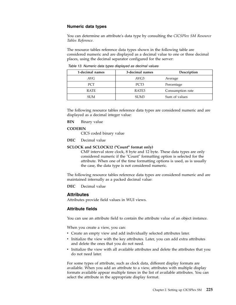
Numeric data types
You can determine an attribute's data type by consulting the CICSPlex SM ResourceTables Reference.
The resource tables reference data types shown in the following table areconsidered numeric and are displayed as a decimal value to one or three decimalplaces, using the decimal separator configured for the server:
Table 13. Numeric data types displayed as decimal values
1-decimal names 3-decimal names Description
AVG AVG3 Average
PCT PCT3 Percentage
RATE RATE3 Consumption rate
SUM SUM3 Sum of values
The following resource tables reference data types are considered numeric and aredisplayed as a decimal integer value:
BIN Binary value
CODEBINCICS coded binary value
DEC Decimal value
SCLOCK and SCLOCK12 ("Count" format only)CMF interval store clock, 8 byte and 12 byte. These data types are onlyconsidered numeric if the "Count" formatting option is selected for theattribute. When one of the time formatting options is used, as is usuallythe case, the data type is not considered numeric.
The following resource tables reference data types are considered numeric and aremaintained internally as a packed decimal value:
DEC Decimal value
AttributesAttributes provide field values in WUI views.
Attribute fields
You can use an attribute field to contain the attribute value of an object instance.
When you create a view, you can:v Create an empty view and add individually selected attributes later.v Initialize the view with the key attributes. Later, you can add extra attributes
and delete the ones that you do not need.v Initialize the view with all available attributes and delete the attributes that you
do not need later.
For some types of attribute, such as clock data, different display formats areavailable. When you add an attribute to a view, attributes with multiple displayformats available appear multiple times in the list of available attributes. You canselect the attribute in the appropriate display format.
Chapter 2. Setting up CICSPlex SM 225

Display formats for time fields
Clock data can be displayed in up to four different formats, depending on the datatype.
Attributes with the data type SCLOCK12, which use the 12-byte CMF interval storeclock, can be displayed in any of the time formats. For attributes with the datatype SCLOCK (the 8-byte store clock), you can use only certain time formats.
In the time formats that include fractions of a second, t is tenths of seconds, h ishundredths of seconds, m is milliseconds, i is ten-thousandths of seconds, j ishundred-thousandths of seconds, and u is microseconds.v HHHH:MM:SS.thmiju, which shows a 4-digit count for hours, and displays the time
to 6 decimal places (down to one microsecond). This format is the default for thedata type SCLOCK12. It is not available for SCLOCK. This format is the same asthe format used in the CICS statistics reports.
v DDD.HH:MM:SS.thmiju, which shows a count for days, and displays the time to 6decimal places (down to one microsecond). This format is available for the datatype SCLOCK12. It is not available for SCLOCK.
v HH:MM:SS.thmi, which shows a 2-digit count for hours, and displays the time to4 decimal places (down to one ten-thousandth of a second). This format is thedefault for the data type SCLOCK, and it is also available for SCLOCK12.
v HH:MM:SS, which shows a 2-digit count for hours and no decimal places. Thisformat is available for both the data types SCLOCK and SCLOCK12.
Choose one of the longer time formats for larger time values, such as those forlong-running tasks, or for time values where you need maximum precision.
For attributes with the data types SCLOCK12 and SCLOCK, you can also display acount. The count is taken from the last 4 bytes of the clock data. It gives thenumber of measurement periods during which the time recorded by the timercomponent of the clock was accumulated.
Attribute filters
You use attribute filters to select the records displayed in a view. The filter for anattribute may be either an entry field or a selection list of possible attribute values.You can edit the selection list to suit the circumstances under which the view willbe used. These attribute filters will always be available to users of this view.
Note: You cannot specify the EYU_CICSNAME or EYU_CICSREL attributes, orattributes with a maximum length over 256 bytes as attribute filters.
ParametersParameters are available for each managed object in CICSPlex SM.
Action parameter fieldsYou can include action parameters on a confirmation panel and ask theuser to select one before the action is implemented.
Parameter filtersParameter filters are available only for certain resource types. You useparameter filters to select the records that are displayed in a view. You candisplay the parameter filter as either an entry field, into which the user cantype a value, or a selection list, from which the user selects a value. Theseparameter filters will always be available to users of this view.
226 CICS TS for z/OS: CICSPlex SM Concepts and Planning

Action buttonsAction buttons allow you to operate on resources and are available on tabularviews and detail views.
All action buttons except the create action button operate on those objects on aview selected by the user. For example, on a CICS region tabular view, selectingone or more CICS regions for shutdown and selecting the Shutdown action buttonwould shut down all of the selected regions. On a detail view, the action affectsonly the managed object displayed in the view. For example, to allow a user toenable or disable a file resource, you could create a detail view with the fileattribute FILESTATUS, and the attribute CVDA values of ENABLED andDISABLED displayed in a selection list. The user could select the value required,and select a SET action button. The action button is labeled Set, by default, but youcan customize the label to display any text, possibly in your national language.
The create action is not related to objects selected on a view. When present on aview, the create action is always available, and functions even on views thatpresent no data.
Action buttons can either:v Issue an appropriate command. This is in the case of a direct action which
requires no confirmation, orv Display a panel to confirm the action, perhaps with fields for further input.
These action buttons automatically have an ellipsis appended to the end of theirlabel.
Customizable view and menu helpIn addition to the Web User Interface help provided with the CICSPlex SM WebUser Interface, you can create help that is tailored to your customized views andmenus, and that provides information relevant to your business procedures.
The help text may be in your national language and might include, for example,site-specific contact names and telephone numbers, or special procedures. You cancreate your customizable view and menu help in a number of ways. For example:v You can edit HTML using a text editor or an HTML editor.v You can export it from a word processor.v You can link to a server that provides access to a database via a Web browser,
for example, Lotus® Domino®.
The help pages can be served either by the Web User Interface server or by anexternal server.
You can use the View Editor to include a link to the customizable view and menuhelp when you create a view. The options are:v Default view-specific help.v Member name of a help page to be served by the Web User Interface from
DFHHTML.v URL of an external help page to be served by another HTTP server. The external
help page should not target the Web User Interface server.
Chapter 2. Setting up CICSPlex SM 227

Considerations when creating pages to be served by the WebUser Interface serverWhen creating your help pages to be served by the Web User Interface server, youshould consider the following:v The names of the help pages must be no more than 8 characters and consist of
uppercase letters and numerical digits.v When developing the help pages on a workstation, name the files with one of
the following extensions as appropriate for your platform:– .htm– .html– .HTM– .HTML
v When uploading the help pages to the DFHHTML data set, use the 8–characterpage name (with the extension removed) as the member name.
You may link between your help pages if you want, perhaps to create a contentspage. To do this, you must specify the page name (including the extension)without any path. For example,<A HREF="PAGE2.HTM">Another Page</A>
This allows you to test your help pages and the links between them before youupload the pages to the DFHHTML data set.
When uploading the help pages to the DFHHTML data set, you do not need tochange any of the links as the Web User Interface server will recognize the pageregardless of the extension you used.
Using the view editorThe CICSPlex SM Web User Interface view editor is the tool for customizing yourmenus, views and map objects.
The navigation frame of the Web User Interface display contains a link to the vieweditor. However, if your Web User Interface server is running with security active,the view editor is restricted to nominated users. You will not see the link to theview editor unless you have the required authority.
You should leave the view editor by returning to the CICSPlex SM Web UserInterface Editor screen or by signing off.
Note:
1. If your web browser session times out, because the INACTIVETIMOUT periodis reached, any changes not saved before the session being timed out are lost.
2. This information uses supplied views to provide examples that show how theview editor can be used to edit views. However, you cannot save changes tothe supplied views and menus. You must copy the required view set and edityour copy. See “Example tasks” on page 244.
3. A view set, menu, or map object is locked whenever it is opened for edit.Changes are not committed until the view set or menu is finally saved or theedit is abandoned. While locked other users cannot edit the same view set ormenu. Users may continue to use the view set or menu while it is being edited,in which case the original version of the view set or menu will be used until itis opened after the changes have been committed.
228 CICS TS for z/OS: CICSPlex SM Concepts and Planning

Accessing the view editorTo access the view editor, select View editor in the navigation frame.
A view editor session is opened in a new window and you are presented with theCICSPlex SM Web User Interface Editor screen. You can have more than oneview editor session running at any one time.
Web User Interface supplied views and menusThe CICSPlex SM Web User Interface includes a set of views and menus that youcan use either as supplied or as the basis from which to create your owncustomized views and menus.
When you work with either menus or views, the supplied menus and view setsare listed in a selection box. You can select the one that you want to base yourcustomized view on.
Note: You cannot save changes to the supplied view sets and menus. View set andmenu names beginning with EYU are reserved for IBM use. You must copy therequired supplied view set or menu then edit your copy.
All supplied views are named EYUSTARTobject, where object is a CICSPlex SMresource table name.
Working with customized menusTo work with menus, select the Menus option from the CICSPlex SM Web UserInterface Editor screen.
You have the options of creating a new menu, editing an existing menu, copyingan existing menu, or deleting a menu.
Working with customized view setsTo work with views, select the View sets option from the CICSPlex SM Web UserInterface Editor screen.
This opens the View Set Editor screen, as shown in Figure 25 on page 230. Youhave the options of creating a new view set, editing an existing view set, copyingan existing view set, or deleting a view set.
Chapter 2. Setting up CICSPlex SM 229
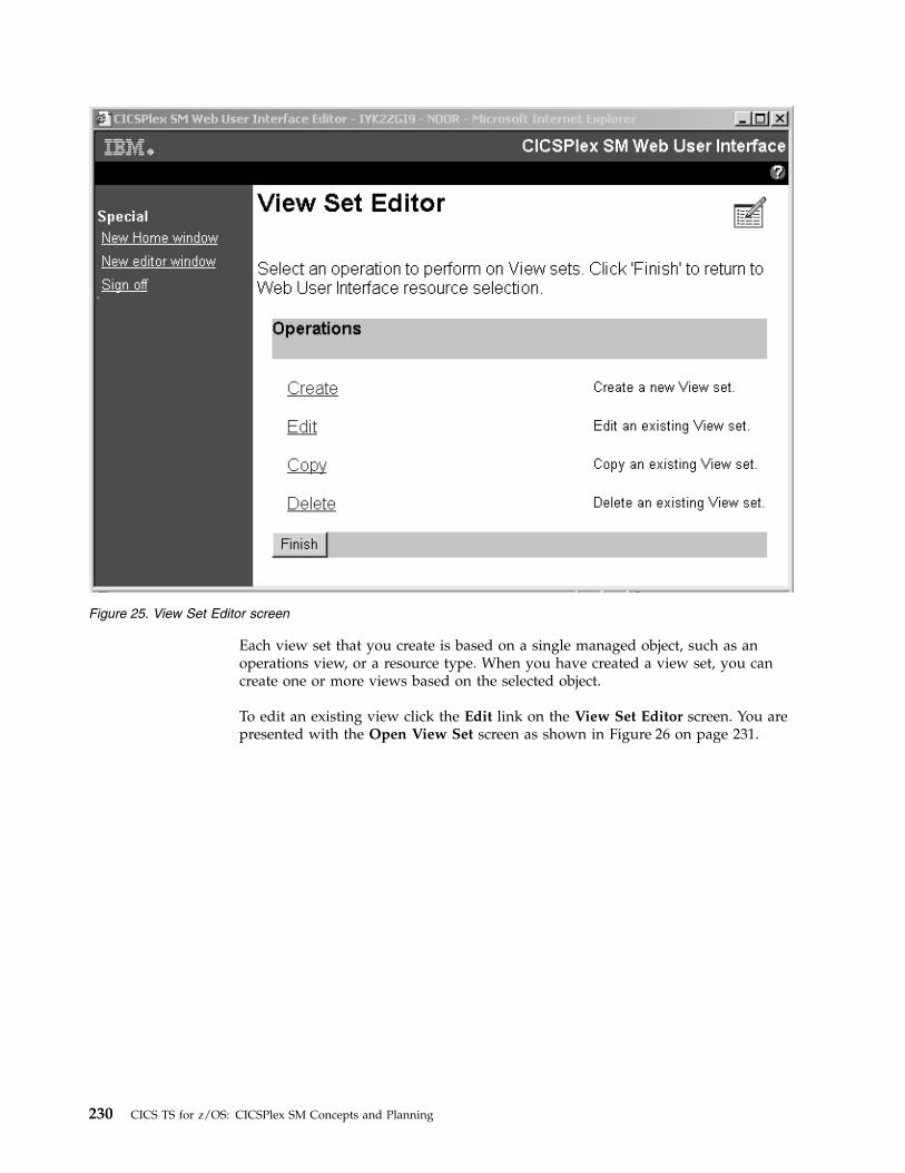
Each view set that you create is based on a single managed object, such as anoperations view, or a resource type. When you have created a view set, you cancreate one or more views based on the selected object.
To edit an existing view click the Edit link on the View Set Editor screen. You arepresented with the Open View Set screen as shown in Figure 26 on page 231.
Figure 25. View Set Editor screen
230 CICS TS for z/OS: CICSPlex SM Concepts and Planning

From the Open View Set screen you can select the view set that you want to editto be presented with the View Set Contents screen similar to the screen shown inFigure 27 on page 232. This screen shows that the selected view set EJBS contains atabular view and a detail view.
Figure 26. Open View Set screen
Chapter 2. Setting up CICSPlex SM 231

From the View Set Contents screen, you can add a new view, edit, copy, or deletean existing view from the view set that you are working with.
Working with customized viewsTo edit an existing view you select the view from the View Set Contents screen byselecting the radio button against the view and clicking Edit.
You can select one view to edit at a time. The View Set Contents screen isredisplayed after editing a view allowing you to select another view to edit, ifrequired.
For example, by selecting the Tabular view from the View Set Contents screen,you will be presented with the Tabular View Components screen shown inFigure 28 on page 233.
Figure 27. View Set Contents screen
232 CICS TS for z/OS: CICSPlex SM Concepts and Planning

From the Tabular View Components screen you select the component that youwant to edit and a new screen is displayed. When you have finished editing yourselection you are returned to the Tabular View Components screen, from whereyou can select another component to edit, click OK to return to the View SetContents screen, or Cancel to lose all the changes that you have made to this viewand return to the View Set Contents screen.
For example, to edit the columns and contents of the EJBS tabular view, select theTable contents component. This displays the Table Contents screen shown inFigure 29 on page 234.
Figure 28. Tabular View Components screen
Chapter 2. Setting up CICSPlex SM 233

From the Table Contents screen you can:v Click Append to add a new column to the end of the table, even if a column has
been selected.v Select a column and click Insert to add a new column before the one that you
have selected.v Select a column and click Edit to edit the contents of the column.v Select a column and click Delete to delete the column.
A column is selected by selecting the radio button in the title box of the column.
When you have finished editing the Table Contents screen, click OK to return tothe Tabular View Components screen from where you may decide to work withthe action buttons available on the Journal Name view.
To edit the action buttons that are available on the EJBS view select the Actionbuttons component.. This displays the View Buttons screen.
Figure 29. Table Contents screen
234 CICS TS for z/OS: CICSPlex SM Concepts and Planning

From the View Buttons screen you may want to add a new button. Click theAppend button, as instructed on this screen, to display the New View Button.
From the New View Button screen you can select the button action:
Figure 30. View Buttons screen
Figure 31. New View Button screen
Chapter 2. Setting up CICSPlex SM 235
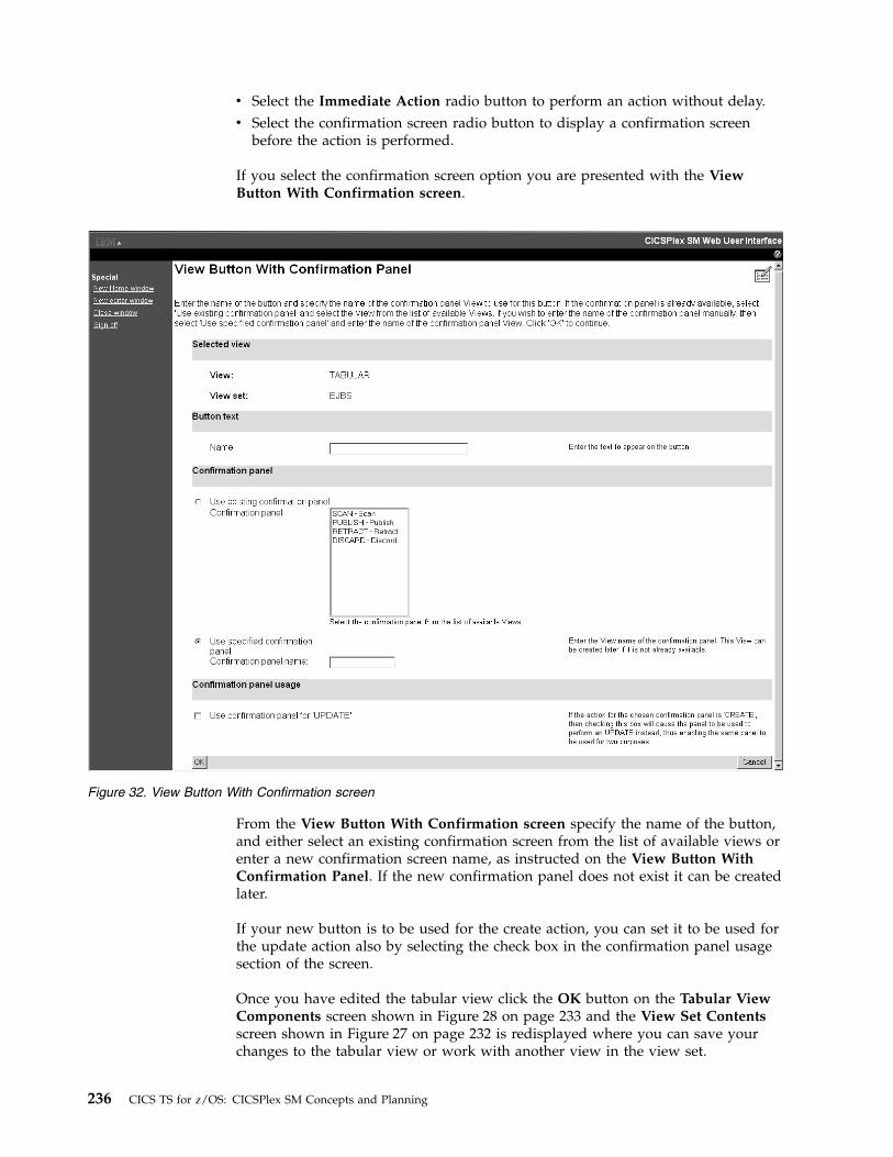
v Select the Immediate Action radio button to perform an action without delay.v Select the confirmation screen radio button to display a confirmation screen
before the action is performed.
If you select the confirmation screen option you are presented with the ViewButton With Confirmation screen.
From the View Button With Confirmation screen specify the name of the button,and either select an existing confirmation screen from the list of available views orenter a new confirmation screen name, as instructed on the View Button WithConfirmation Panel. If the new confirmation panel does not exist it can be createdlater.
If your new button is to be used for the create action, you can set it to be used forthe update action also by selecting the check box in the confirmation panel usagesection of the screen.
Once you have edited the tabular view click the OK button on the Tabular ViewComponents screen shown in Figure 28 on page 233 and the View Set Contentsscreen shown in Figure 27 on page 232 is redisplayed where you can save yourchanges to the tabular view or work with another view in the view set.
Figure 32. View Button With Confirmation screen
236 CICS TS for z/OS: CICSPlex SM Concepts and Planning

Note: Some attribute fields are derived from CICS CMF performance classmonitoring data. In order for these fields to function correctly, you need to ensurethat the CICS monitoring facility is active by setting the CICS system initializationparameters MNPER and MNRES to YES.
Working with view componentsFrom the Tabular View Components screen you select the component that youwant to edit and a new screen is displayed.
When you have finished editing your selection you are returned to the TabularView Components screen, from where you can select another component to edit,click OK to return to the View Set Contents screen, or Cancel to lose all thechanges that you have made to this view and return to the View Set Contentsscreen.
For example, to edit the columns and contents of the EJBS tabular view, select theTable contents component. This displays the Table Contents screen shown inFigure 33.
From the Table Contents screen you can:v Click Append to add a new column to the end of the table, even if a column has
been selected.v Select a column and click Insert to add a new column before the one that you
have selected.v Select a column and click Edit to edit the contents of the column.v Select a column and click Delete to delete the column.
A column is selected by selecting the radio button in the title box of the column.
Figure 33. Table Contents screen
Chapter 2. Setting up CICSPlex SM 237
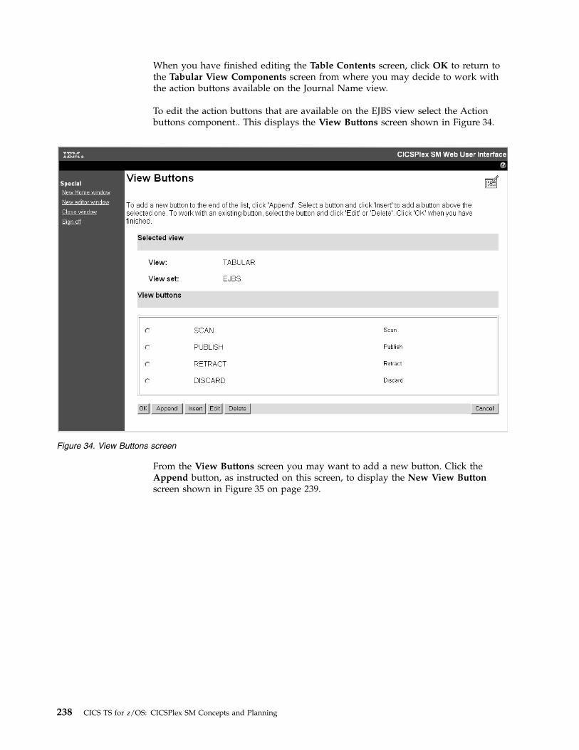
When you have finished editing the Table Contents screen, click OK to return tothe Tabular View Components screen from where you may decide to work withthe action buttons available on the Journal Name view.
To edit the action buttons that are available on the EJBS view select the Actionbuttons component.. This displays the View Buttons screen shown in Figure 34.
From the View Buttons screen you may want to add a new button. Click theAppend button, as instructed on this screen, to display the New View Buttonscreen shown in Figure 35 on page 239.
Figure 34. View Buttons screen
238 CICS TS for z/OS: CICSPlex SM Concepts and Planning

From the New View Button screen you can select the button action:v Select the Immediate Action radio button to perform an action without delay.v Select the confirmation screen radio button to display a confirmation screen
before the action is performed.
If you select the confirmation screen option you are presented with the ViewButton With Confirmation screen shown in Figure 36 on page 240.
Figure 35. NewView Button screen
Chapter 2. Setting up CICSPlex SM 239

From the View Button With Confirmation screen specify the name of the button,and either select an existing confirmation screen from the list of available views orenter a new confirmation screen name, as instructed on the View Button WithConfirmation Panel. If the new confirmation panel does not exist it can be createdlater.
If your new button is to be used for the create action, you can set it to be used forthe update action also by selecting the check box in the confirmation panel usagesection of the screen.
Once you have edited the tabular view click the OK button on the Tabular ViewComponents screen shown in Figure 28 on page 233 and the View Set Contentsscreen shown in Figure 27 on page 232 is redisplayed where you can save yourchanges to the tabular view or work with another view in the view set.
Note: Some attribute fields are derived from CICS CMF performance classmonitoring data. In order for these fields to function correctly, you need to ensurethat the CICS monitoring facility is active by setting the CICS system initializationparameters MNPER and MNRES to YES.
Working with customized map objectsYou can use the view editor to create and edit customized map objects.
Figure 36. View Button With Confirmation screen
240 CICS TS for z/OS: CICSPlex SM Concepts and Planning

Enabling the map function on a customized view:
To enable the map function on a customized view, use the view editor to add amap button.
Before you begin
You can add a map button to any tabular or detail view that relates to adefinitional object.
About this task
The following task describes how to add a map button to a tabular view. The taskassumes that you have already created a tabular view as a target for this operation.If you want to add a map button to a detailed view the procedure is the same butthe Tabular View Components screen is replaced by the Detailed FormComponents screen.
Procedure
1. Open the view editor, click View sets > Edit, and select the view set containingyour target view from the list.
2. Click OK to open the View Set Contents panel, which lists all of the views inyour selected view set.
3. Select the target view from the list and click Edit to open the Tabular ViewComponents panel.
4. Click Tabular View display options to open the View display options panel.The panel displays a number of headings.
5. Scroll to the Map button section and select Map button available. Click OK toreturn to the Tabular View Components panel.
6. Assuming you are not making any more changes to the view, click OK toreturn to the View Set Contents panel and then Save to confirm the operation.
Results
Your view now includes a map button. If the selected resource type can generatemore than one type of map, for example Monitoring and RTA in the case of a timeperiod definition, the view also contains a drop-down box next to the map buttonlisting the available choices.
What to do next
When you click Map on your newly customized view, a map of associateddefinitions is generated. Unless you have specified otherwise, the map generated isbased on the default supplied map object for that resource type. You can alter thisbehavior by specifying a customized map in the WUI server initializationparameters during system setup, or for a particular group of users in a user groupprofile.
Creating a customized map object:
You can create your own map objects for resource types to customize the map'shyperlinks. This process is in two-stages. First you create the map using the vieweditor, and then associate it with resources to make it accessible.
Chapter 2. Setting up CICSPlex SM 241

Before you begin
The view editor includes a number of panels to enable you to create and edit yourown maps as shown in Figure 37.
Maps contain mostly standard elements that cannot be changed. The purpose ofcreating your own map objects is to customize the map's hyperlinks. On a suppliedmap, clicking one of the displayed resource names takes you to a detailed view ofthat resource definition. On a customized map object, you can change this behaviorto link to any detailed view, including customized views, that relates to the sameobject type. For example, you can link from a CSYSDEF resource to anyCSYSDEF-related view. However, you cannot link from a CSYSDEF resource to aPROGDEF-related view, for example.
Before you can create and edit maps, you must have update authority to thesecurity profile that most closely matches the map object. A security profile of theform EYUWUI.wui_server_applid.MAP.mapname governs access to map objects in anexternal security manager.
Standard View Editor
Edit Hyperlinks Screen
View Editor
MenusView setsMaps
Map Editor
CreateEditCopyDelete
Finish
Copy Map
Select:
Name:
OK Cancel
Delete Map
Select:
OK Cancel
Confirm Delete
Name:
OK Cancel
Edit Map
Select:
OK Cancel
Create Map
Name:
Type:
OK Cancel
WLMRTABASMON
Edit Hyperlinks
Save Edit Abandon
Col1 Col2 Col3 Col4
Figure 37. Map editing panels in the View Editor
242 CICS TS for z/OS: CICSPlex SM Concepts and Planning

You can import and export customized map definitions using the COVCtransaction.
About this task
You can create a new map object in two ways; you can either copy and rename anexisting one, or create a new one from scratch. The procedures are very similar.Follow this procedure to create one from scratch:
Procedure
1. Open the view editor and click Maps to open the main Map Editor panel fromwhich you can choose to create, edit, copy, or delete a map.
2. Click Create to open the Create Map panel.3. Type in a name for your new map object. Map object names consist of letters
and digits and have a maximum length of 16 characters.4. Select the type of map you want to create from workload management (WLM),
real-time analysis (RTA), business application services (BAS) or monitoring(MON). Choose one and click OK to continue. The Edit Hyperlinks panelopens, which shows the resource columns in your new map. The number ofcolumns varies according to the type of map you are creating; BAS, WLM, andmonitoring maps have five resource columns, RTA maps have six.
5. Select a column and click Edit to set its hyperlink. The Target view set panelopens.
6. Select the view set that includes the target view for the hyperlink, or enter thename of the view set, and then click OK.
7. This opens the Target View panel. This panel gives you three choices:v Select Default View name to link to the supplied view that is the default for
the resource type.v Select Use an existing View and select a view from the list to link to an
existing supplied or customized view.v Select Use a specified View and type in a view name to link to a new view
that has not been created yet.
Make your selection and click OK to continue. This takes you back to the EditHyperlinks panel. The hyperlink for the column you selected in step 7 is nowset. You can now continue to set the other columns by repeating steps 5 to 7.
8. When you have finished setting the hyperlinks, click Save on the EditHyperlinks panel to save your new map screen in the data repository. MessageEYUVE1030I confirms that the operation has been successful.
Results
The alternative method of creating a new map object is to copy an existing one andedit it. To do this, select Copy from the Map Editor panel, select an existing mapand give it a new name. Now you can select Edit from the Map Editor panel toupdate the new map's hyperlinks.
Having created a map object, you must associate it with the appropriate resourcetype before you can use it. You can do this in two ways:v You can specify the association when you are configuring your WUI using the
following WUI server initialization parameters:DEFAULTMAPBAS for a BAS mapDEFAULTMAPMON for a monitoring map
Chapter 2. Setting up CICSPlex SM 243
DEFAULTMAPRTA for an RTA mapDEFAULTMAPWLM for a WLM map.
v You can specify the association in a user group profile so that you can specifydifferent map associations for different groups of users. Using this methodmeans that you do not have to stop and reconfigure your WUI server.
Applying or rejecting updatesThe view editor provides buttons that allow you to commit or cancel updates.
CancelCancel the operation represented by the screen and any changes made aspart of the operation.
OK Submit the changes and continue.
Finish Return to the previous screen.
Save Save the changes associated with a view set or menu in the Web UserInterface server repository.
AbandonDo not save the changes associated with a view set or menu in the WebUser Interface server repository.
The Cancel and OK buttons appear together, as do the Save and Abandonbuttons, on view editor panels.
Note: If your web browser session times out, because the INACTIVETIMOUTperiod is reached, any changes not saved before the session being timed out arelost. For information about the INACTIVETIMEOUT Web User Interface serverinitialization parameter, see Web User Interface server initialization parameters.
Example tasksTwo typical tasks illustrate some of the customization facilities offered by the WebUser Interface view editor. In both cases, the starting point is a supplied view set.
The view editor guides you with additional on-screen instructions.
Using view links and attribute filters:
This sample task describes how to link from a tabular view of task resources to adetail view displaying terminal information, when the principal facility is aterminal.
The task involves editing a copy of the supplied view to add a new column for theFACILITY attribute, setting up a conditional link and supplying an attribute filter.
The FACILITY attribute column will be defined to link to a view for the TERMNLresource when the attribute contains a terminal ID. This is achieved by making thelink conditional on the value of the FACILITYTYPE attribute and using an attributefilter to specify that the TERMID of the target resource is equal to the FACILITY ofthe source.
For information on the attributes, see CICSPlex SM resource tables.1. Prepare the view set
a. Copy the supplied view set EYUSTARTTASK with the new nameTASKVIEWSET (This name is an example only).
244 CICS TS for z/OS: CICSPlex SM Concepts and Planning

b. On the View Set Editor screen, click Edit and, from the Open View Setscreen, select TASKVIEWSET from the list.
c. On the View Set Contents screen, select the view called TABULAR andclick the Edit button.
2. Add a column
a. On the Tabular View Components screen, select Table contents. The tablelayout is displayed.
b. Select the User ID column by selecting the radio button in the columnheading. Click the Insert button. This inserts the new column before theUser ID column.
c. On the New Table Column Attribute screen, select FACILITY from theattribute list and click OK.
3. Create a conditional link
a. On the Table Column Components screen, click View links.b. On the View Links screen, click Append.c. On the New View Link Type screen, select the View set radio button to
link to a view within another view set and click OK.d. On the View Link Condition screen, the View link conditional on
Attribute check box is selected by default. Select FACILITYTYPE and clickOK.
e. On the View Link Components screen, select Condition test.f. On the View Link Condition screen, select the condition attribute test radio
button Is valid and equal to and select TERM in the selection list. Click OK.4. Specify the target view set and view
a. On the View Link Components screen, select Target.b. On the Local Target Link screen, the Target view set selected from list
radio button is selected by default. Select the name of the supplied viewEYUSTARTTERMNL from the selection list and click OK.
c. On the Confirm Object for View Set screen, confirm that the object typeTERMNL is already highlighted and click OK.
d. From the Target View screen, select the Target view selected from list radiobutton, select the view called DETAILED and click OK.
5. Specify target selection criteria
a. On the View Link Components screen, select Context and Scope.b. On the View Link Context and Scope Settings screen, retain the context
and CMAS context defaults. Change the scope setting by selecting the Setto value of attribute radio button. Select EYU_CICSNAME and click OK.
c. On the View Link Components screen, select Filter attributes andparameters.
d. On the View Link Filters screen, click the Append button. On the ViewLink Filter Type screen, the Attribute filter radio button is selected bydefault. Click OK.
e. On the View Link Filter screen, select the TERMID filter attribute and clickOK.
f. On the View Link Filter Settings screen, the equals operator is selected bydefault. If the FACILITYTYPE field contains the value TERM, the FACILITYfield contains a terminal ID. Select the Value of attribute radio button andselect filter value FACILITY from the selection list. (The FACILITY fieldcontains a terminal ID if the FACILITYTYPE field contains TERM.) ClickOK.
Chapter 2. Setting up CICSPlex SM 245

6. Save your changes
a. Return to the View Set Contents screen by selecting the appropriatebuttons on the screens to save your changes. The buttons have differentnames depending on the function, and may be labeled OK or Finish.
b. On the View Set Contents screen, you have the choice of saving orabandoning your changes.
You can test your view by creating a link from a menu, or see Providing access toWUI views and menus for information on how to display your view directly.
Using warning lights:
This sample task describes how you can replace the textual representation of eventseverity data in a tabular view with warning lights.
Figure 38 shows detail of the Real Time Analysis (RTA) outstanding events view(EYUSTARTEVENT.TABULAR) as supplied, which is used as the basis for thistask. This sample task sets a flashing red warning light for the Very High Severitylevel. You can make your own choice for the other event severity levels.
Figure 38. Detail of view with text representation of event severity levels
246 CICS TS for z/OS: CICSPlex SM Concepts and Planning

1. Prepare the view set
a. Copy the supplied view set EYUSTARTEVENT with the new nameEVENTVIEWSET.
b. On the View Set Editor screen, click Edit, and on the Open View Setscreen, select EVENTVIEWSET from the view set list.
c. On the View Set Contents screen, select the view called TABULAR andclick Edit. On the Tabular View Components screen, select Table contents.The table layout is displayed.
2. Add warning lights to the Event Severity column
a. Select the Event Severity column by selecting the radio button in thecolumn heading. Click Edit.
b. On the Table Column Components screen, select Presentation options.c. On the Presentation type screen, select the Warning lights radio button and
click OK.d. On the Presentation Options screen, select the Show value radio button. It
is good practice to have the value displayed as well as the colored lights.Click OK.
3. Set the color thresholds
a. On the Presentation thresholds screen, click the Append button, and on thePresentation Threshold Components screen, select Threshold range.
b. On the Presentation Threshold Range screen, the Equal to field is selectedby default. In the entry field, type the attribute value VHS. This is the valuethat will cause this color. Click OK.
c. On the Presentation Thresholds Components screen, select Thresholdcolor.
Figure 39. Detail of view with warning light representation of event severity levels
Chapter 2. Setting up CICSPlex SM 247

d. On the Presentation Threshold Color screen, select the color RED. Selectthe Flashing check box and click OK.
e. On the Presentation Thresholds Components screen, click Finish to returnto the Presentation Thresholds screen.
f. Repeat these steps for each value that you want to define a color for,selecting the color required. When you have created all your presentationthresholds, click the OK button on the Presentation Thresholds screen.When no color is specified for a particular value, the color on the displaywill be grey.
4. Save your changes
a. Return to the View Set Contents screen by selecting on the appropriatebuttons on the screens to save your changes. The buttons have differentnames depending on the function, and are either labeled OK or Finish.
b. On the View Set Contents screen, you have the choice of saving orabandoning your changes.
You can test your view by creating a link from a menu, or see Providing access toWUI views and menus for information on how to display your view directly. Yourview might look like the example in Figure 39 on page 247.
Creating a two-column detailed view:
You can create a two-column detailed views using the WUI view editor.
Procedure
1. Open the view editor and navigate to the Add View screen.a. From the main menu navigation screen, click View editor > View sets >
Edit. The Open View Set screen is shown.b. Select the view set to which your new detailed view will belong, and click
OK to open the View Set Contents screen.c. Click Add. The Add View screen is shown, which you can use to create a
new view for the selected view set.2. Name the new view and define its display type.
a. Type in a name for your new view in the View name field.b. Select Two column detail form from the list of view types.c. Select Key attributes from the list of pre-fill options, and click OK. The
Detailed Form Components screen is shown.3. Add an attribute to the left column. When you choose to add an item to a
two-column detail view, the new element is placed in the left column. In orderto maintain left right alignment, a white space element is automatically placedin the right column opposite the new item.a. Select Form contents. This opens a Form Contents screen like the one
shown in Figure 40 on page 249.
248 CICS TS for z/OS: CICSPlex SM Concepts and Planning

Notice it contains a Space element type, which is necessary in the creationof two column screens in order to balance the right and left columns.
b. Click Append. The Form Item Type screen is shown.c. Select Attribute field and click OK to open the Form Attribute Field screen.
This screen contains a list of attributes including the attribute name, dataformat, and a short description.
d. Select an attribute from the list and click OK to open the Form ItemComponents screen.
e. Check the radio button of the attribute, and complete the definition of thenew attribute as follows:1) Type in the attribute title and any annotation.2) Select the display options, either normal or graphical.3) Add any view links.
f. Click Finish to add the new attribute to your new view. You are back to theForm Contents screen.
4. Add an attribute to the right hand column of the view. In order to add anelement to the right hand column, you need to select a white space elementand then edit it to change it to the type of element required.a. Select the white space element created in step 3 and click Edit. The Form
Item Type screen is shown.b. Select the type of element you want to add to the right hand column, and
follow the procedure outlined in step 3 to define it.c. Click Finish to add the right hand element to the view.
Note: You can repeat steps 3 and 4 as many times as necessary to add moreelements to the left and right columns.
Figure 40. Form contents screen for a two-column detail view
Chapter 2. Setting up CICSPlex SM 249

If you want to remove an item from the right hand column, select it and clickDelete item. This converts the item back to a white space element.
Note: You cannot delete an individual white space element but you canremove adjacent elements in both columns by clicking Delete row.
5. Complete the view definition as follows:a. Click OK on the Form Contents screen to return to the Detailed Form
Components screen.b. Add the rest of the components of the new view including a title, action
buttons, filters, context and scope and so on.c. When you have added all the required components, click OK to save the
new view and return to the View Set Contents screen.
Example
Figure 41 on page 251 shows an example of a two-column detail view.
250 CICS TS for z/OS: CICSPlex SM Concepts and Planning

Creating a filter confirmation screen:
You can use the view editor to set up filter confirmation for an existing (userdesigned) view.1. Start the view editor and click Menus to open the Menu Editor.2. Click Edit and select the menu containing the hyperlink to the intended view
from the list. This opens the Menu Components screen.
Figure 41. Example of a two-column detail view
Chapter 2. Setting up CICSPlex SM 251

3. Click Menu Contents, then scroll to the bottom of the Menu Contents screenand click Append. This opens the New Menu Item screen.
4. Select the Menu choice radio button and click OK. This opens the MenuChoice Components screen.
5. Click Destination to open the Menu Choice Type screen then select the Viewlink radio button. This opens the Target View Set screen similar to the oneshown in Figure 42.
6. Select the view set that includes the target view and click OK. This opens theConfirm Object for View Set screen.
7. Just for confirmation, select the object associated with your selected view setand click OK. This opens a Target View screen similar to Figure 43 on page253.
Figure 42. Target View Set screen
252 CICS TS for z/OS: CICSPlex SM Concepts and Planning

8. To create a filter confirmation screen associated with the selected view, scroll tothe bottom of the screen and select the box labelled Use filter confirmationbefore get. Click OK to confirm.
Now, before opening the target view, a filter confirmation screen is displayedallowing users to specify filter criteria before data retrieval takes place.
Configuring workload managementCICSPlex SM workload management optimizes processor capacity in yourenterprise by dynamically routing transactions and programs to whichever CICSregion is the most appropriate at the time, taking into account any transactionaffinities that exist.
Before you begin1. Ensure that you are familiar with the concepts involved with workload
management and the dynamic routing of transactions and programs. Fordetails, see Overview of CICSPlex SM workload management.
Figure 43. Target View screen showing filter confirmation box
Chapter 2. Setting up CICSPlex SM 253

2. You have determined the extent to which you can use CICSPlex SM workloadmanagement in your enterprise. This includes identifying the workloadsprocessed in your enterprise and inter-transaction affinities. Follow theinstructions in Planning for WLM.
3. Ensure that you follow the implementation process described in ImplementingWLM.
About this task
When you establish a workload, you are associating the work itself and the CICSsystems (acting as requesting, routing, and target regions), to form a single,dynamic entity. Within this entity, you can route the work:v To a target region selected on the basis of its availability. This type of routing,
known as workload balancing, allows you to balance work activity across all of thetarget regions associated with a workload. See “Management of the work in aworkload” on page 256 for additional information.
v To a subset of the target regions based on specific criteria. This type of routing,known as workload separation, allows you to separate transaction and programoccurrences and direct them to different target region subsets, where activity isbalanced across the target regions within the subset.The criteria you use to separate transactions or programs can be based on:– The terminal ID and user ID associated with a transaction or program
occurrence.– The process type associated with the CICS BTS activity.– The transaction.
See “Separating the work in a workload” on page 259 for additional information.v To a selected target region based on its affinity relationship and lifetime. This
type of routing, based on the transaction affinity of the target region, allows youto route specific transaction occurrences to the same target region for adesignated period of time. For additional information, see “Taking affinityrelations into consideration” on page 264.
Workload routing and workload separation can be active concurrently in the sameor different workloads associated with a CICSplex.
Note:
1. You can use the CICSPlex SM real-time analysis functions to produce data thatwill help in the selection of a target region during workload management. SeeUsing real-time analysis to select a target region for workload routing fordetails.
2. For additional information about how CICSPlex SM handles dynamic routingand how you can customize this facility, see “Dynamic routing withCICSPlex SM” on page 270.
Procedure
Workload requirementsAny CICS system can act as a requesting region, a routing region, or a targetregion, under certain conditions.v All the CICS systems associated with a workload are either part of the same
CICSplex, or, for BTS processes and activities, part of the same BTS-set. They donot have to reside in the same MVS image.
254 CICS TS for z/OS: CICSPlex SM Concepts and Planning

v For dynamic routing of both terminal-related and non-terminal-related EXEC CICSSTART commands, requesting, routing, and target regions must be a supportedrelease of CICS Transaction Server.
v For dynamic routing of DPLs, routing regions must be a supported release ofCICS Transaction Server; target regions can be any level of CICS.
v For CICS BTS activities, the routing region (which is also the requesting region)and the target region must be a supported release of CICS Transaction Server.They must also be in the same sysplex.
v For dynamic routing of transactions and static routing, the CICS system actingas the routing region must be running CICS Transaction Server. The CICSsystems acting as target regions can be running any version of any CICSplatform supported by CICSPlex SM.
v For dynamic routing of enterprise bean-related transactions, the CICS systemacting as the routing region and the target region must be running a supportedrelease of CICS Transaction Server.
v The routing region must be defined as local to a CMAS involved in managingthe CICSplex. It must use CICSPlex SM facilities to communicate with thatCMAS.
v For Link3270 bridge requests the target regions must be a supported release ofCICS Transaction Server.
v The regions involved in workload management must have an in-service andACQUIRED connection to each other.
A CICS system can act as a target region in one or more workloads; however, itcan act as a routing region in only one workload.
Note: A CICS system can act as a routing region and a target region in the sameworkload.
When a CICS system acting as a target region is combined with other targetregions to form a CICS system group, each of the target regions must have accessto all the resources required by any transactions that might be routed to that CICSsystem group. In the case of a CICS BTS workload, they must all be in the samesysplex.
Establishing a workloadThe criteria used to identify a workload are based on the information provided bya workload specification, one or more workload definitions and their optionaltransaction groups, and one or more workload groups.v A workload specification identifies the CICS systems or CICS system groups in a
CICSplex that are to be treated as routing regions and the default target regions.You can also use a workload specification to identify a default affinityrelationship and lifetime.A CICS region can be associated with none, or one, workload specification(WLMSPEC). For the CICS region to be a CICSPlex SM routing region, it mustbe associated with a workload. For the CICS region to be a CICSPlex SM targetregion, it depends on the type of routing being used:– For dynamic routing, the target region is not associated with a workload
(WLMSPEC). The target region can be a target for one or more workloads.– For distributed routing, the target region must be associated with a workload
(WLMSPEC). The target region can be a target for one workload.
Chapter 2. Setting up CICSPlex SM 255

If you currently use only dynamic routing, it is advisable that a target region is atarget for only one workload. This simplifies the situation if you decide toimplement distributed routing later.The name of a workload specification becomes the name of the workload itself.
v A workload definition includes specific or generic terminal and user names, or aspecific or generic process type, that are used when attempting to match atransaction occurrence to a workload definition. It also identifies the targetregion to which transaction occurrences matching the criteria are to be routed.
v A transaction group identifies one or more related transaction identifiers andindicates whether the terminal id or the user id specified in the workloaddefinition is to be used as the primary selection criterion in determining whichtransactions are to be routed to the set of target regions identified in theworkload definition. A transaction group is also used to define affinities.
v A workload group is a collection of workload definitions that are to be treated as asingle entity.
Note: When no workload definitions are installed in a workload, all transactionsand programs are routed to a target region in the default target scope identified bythe workload specification. However, when a workload definition is installed in aworkload, all transactions and programs that match the criteria in that workloaddefinition are routed to a target region in the target scope identified by thedefinition itself. A dynamic routing request that is not associated with anyworkload definition is routed to a target region in the default target scope of theworkload specification.
Management of the work in a workloadAll dynamic transactions and programs that are initiated from a set of requestingregions can be routed by a routing region to a specific set of target regions in thesame CICSplex.
The specific target region to which each request is routed is determined by theactivity and availability of all target regions in that set.
To establish workload routing, you need to define only a workload specification.
The dynamic routing processes are explained using Figure 44 on page 257, whichillustrates the Starter Set configuration. For dynamic transaction routing, anytransaction initiated from a terminal associated with the requesting regionEYUMAS1A (a TOR) is routed to the most appropriate target region (an AOR) inthe CICS system group EYUCSG01.
256 CICS TS for z/OS: CICSPlex SM Concepts and Planning

For dynamic routing of EXEC CICS START TRANSID TERMID commands, anytransaction initiated in the requesting region EYUMAS2A (an AOR) is sent toEYUMAS1A (a TOR), the routing region associated with the terminal identified inthe TERMID option of the START command. The routing region sends thetransaction to the most appropriate target region (an AOR) in the CICS systemgroup EYUCSG01.
For dynamic program linking, there are two possible scenarios. For an inboundclient request, the request is received in TOR EYUMAS1A, which acts as therequesting region and the routing region. The target region is any AOR in the CICSsystem group EYUCSG01. For a peer-to-peer request, the request is initiated by atransaction running in EYUMAS2A (an AOR). EYUMAS2A acts as the routingregion, and the target region may be any AOR in the CICS system groupEYUCSG01.
Using the queue algorithm
During workload processing using the queue algorithm, CICSPlex SM routes alltransactions and programs initiated in the requesting region to the mostappropriate target region in the designated set of target regions. See The queuealgorithm.
Using the link neutral queue algorithm
The link neutral queue (LNQUEUE) algorithm corresponds to the queue algorithm,except that the type of connection between the routing and target region is notconsidered. See The link neutral queue algorithm.
Data Repository
Workload Specifications
Name: EYUWMS01Match: userid/lunameTarget Scope: EYUCSG01Routing Scope: EYUMAS1AAlgorithm: QUEUE
CICSplex - EYUPLX01
System Group - EYUCSG01
MVS/ESASystemB
MVS/ESASystemA
(TOR)EYUMAS1A
(AOR)EYUMAS2A
(AOR)EYUMAS3A
(FOR)EYUMAS4A
MAS MAS MAS MAS
(Maintenancepoint)
EYUCMS1A
CMAS
EYUCSG05
(AOR)EYUMAS1B
MAS
Figure 44. Sample workload definition for dynamic routing
Chapter 2. Setting up CICSPlex SM 257

Using the goal algorithm
CICSPlex SM supports the z/OS goal algorithm. The goal algorithm selects thetarget region that is best able to meet the defined, average, or percentileresponse-time goals for all work in a workload.
The goal is defined by associating transactions, using the z/OS Workload Manager,to a service class. Service classes are assigned on a transaction, LU name, and userID basis. Service classes can define several types of response-time goals. However,CICSPlex SM recognizes average and percentile response-time goals only. Iftransactions are given velocity or discretionary goals, they are assumed to bemeeting their goals. CICSPlex SM manages at the service-class level; that is, it hasno internal knowledge of the transaction characteristics. By consistently allocatingservice classes to sets of target regions, it minimizes the amount of resourcereallocation by the z/OS Workload Manager.
You can use goal mode to provide efficient routing decisions, where routers andtargets are managed by the same CMAS, in the following scenarios:v Dynamic routing using DTRPGM for dynamic transactionsv Dynamic routing using DTRPGM for EXEC CICS START TERMID over APPC or
MRO connectionsv Distributed routing using DSRTPGM for business transaction service routing
For additional information about the goal algorithm, see The goal algorithm andz/OS MVS Planning: Workload Management.
The service level administrator must define goals that are realistic for theunderlying capacity of the target systems. Transactions of like attributes (forexample, transactions that have similar resource consumption, orpseudoconversational transactions) must be assigned to distinct service classes. Theresponse-time goals can be the same for several service classes. Use CICS statisticsto help you define these transaction sets. See Improving performance forinformation about CICS statistics.
Using the link neutral goal algorithm
The link neutral goal (LNGOAL) algorithm corresponds to the goal algorithm,except that the type of connection between the routing and target region is notconsidered. See The link neutral goal algorithm.
Control level for workload routing
To use workload routing, you must specify a default routing algorithm for theworkload at the workload specification (WLMSPEC) level. You can optionallyspecify a routing algorithm at the transaction group (TRANGRP) level. Analgorithm specified in a transaction group overrides the default algorithm that isassociated with the workload specification.
The default routing algorithm is applied to every routed dynamic transaction inthe workload, except those transactions that are associated with a transactiongroup that has a routing algorithm specified. You can specify one of the followingrouting algorithms:v QUEUEv LNQUEUE
258 CICS TS for z/OS: CICSPlex SM Concepts and Planning

v GOALv LNGOAL
To change the routing algorithm specified at the workload specification level, youmust close down all regions that participate in the workload so that workload isrefreshed with the new algorithm specification.
At the transaction group level, you can specify a routing algorithm dynamically.The specified dynamic routing algorithm is applied to every routed dynamictransaction that is associated with the transaction group. Therefore, you can applyan alternative routing algorithm to specific transaction codes in the same workload.
If you specify an alternative routing algorithm at the transaction group level, youcan change workload routing characteristics for specific target regions dynamicallywithout stopping your routing region. If you modify an installed transactiongroup, you must discard its associated WLM definition (WLMDEF) and thenreinstall it, so that the transaction group named by the WLM definition is alsorefreshed. To change the routing algorithm type immediately without discardingand reinstalling the associated WLMDEF, you can use the Active workloadtransaction groups (WLMATGRP) views and the SET command to change theALGTYPE attribute.
You can specify one of the following routing algorithms:v INHERITv QUEUEv LNQUEUEv GOALv LNGOAL
INHERIT means that transaction group uses the routing algorithm that isassociated with the workload specification for the workload.
Separating the work in a workloadYou can separate the work in a workload using the name of the user, the terminal,or both that are associated with a transaction or program, the transaction itself, orthe BTS process-type associated with the transaction.
You can separate a workload using either LU name and user ID, or process type.You cannot separate a workload using, for example, a generic process type and auser ID. Separation of enterprise bean workloads may be implemented onlythrough the user ID.
Separating by terminal or user name:
You can create a workload that routes requests from a set of requesting regions todifferent subsets of target regions based on the name of the terminal, user, or bothassociated with each occurrence of a transaction.
For example, you might want to route all requests initiated by certain individualsfrom specific terminals to a special subset of target regions.
Figure 45 on page 260 illustrates what such a workload might look like. In thiscase, if the user and terminal names associated with a transaction begin with SMand NET, respectively, the transaction is routed to the set of target regionsidentified as EYUCSG05. If either the user or terminal name begins with any other
Chapter 2. Setting up CICSPlex SM 259
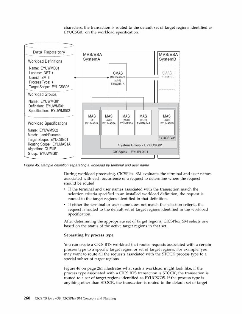
characters, the transaction is routed to the default set of target regions identified asEYUCSG01 on the workload specification.
During workload processing, CICSPlex SM evaluates the terminal and user namesassociated with each occurrence of a request to determine where the requestshould be routed.v If the terminal and user names associated with the transaction match the
selection criteria specified in an installed workload definition, the request isrouted to the target regions identified in that definition.
v If either the terminal or user name does not match the selection criteria, therequest is routed to the default set of target regions identified in the workloadspecification.
After determining the appropriate set of target regions, CICSPlex SM selects onebased on the status of the active target regions in that set.
Separating by process type:
You can create a CICS BTS workload that routes requests associated with a certainprocess type to a specific target region or set of target regions. For example, youmay want to route all the requests associated with the STOCK process type to aspecial subset of target regions.
Figure 46 on page 261 illustrates what such a workload might look like, if theprocess type associated with a CICS BTS transaction is STOCK, the transaction isrouted to a set of target regions identified as EYUCSG05. If the process type isanything other than STOCK, the transaction is routed to the default set of target
Workload Definitions
Name: EYUWMD01Luname: NETUserid: SMProcess Type:Target Scope: EYUCSG05
Workload Groups
Name: EYUWMG01Definition: EYUWMD01Specification: EYUWMS02
Data Repository
Workload Specifications
Name: EYUWMS02Match: userid/lunameTarget Scope: EYUCSG01Routing Scope: EYUMAS1AAlgorithm: QUEUEGroup: EYUWMG01 CICSplex - EYUPLX01
System Group - EYUCSG01
MVS/ESASystemB
MVS/ESASystemA
(TOR)EYUMAS1A
(AOR)EYUMAS2A
(AOR)EYUMAS3A
(FOR)EYUMAS4A
MAS MAS MAS MAS
(Maintenancepoint)
EYUCMS1A
CMAS
EYUCSG05
(AOR)EYUMAS1B
MAS
Figure 45. Sample definition separating a workload by terminal and user name
260 CICS TS for z/OS: CICSPlex SM Concepts and Planning
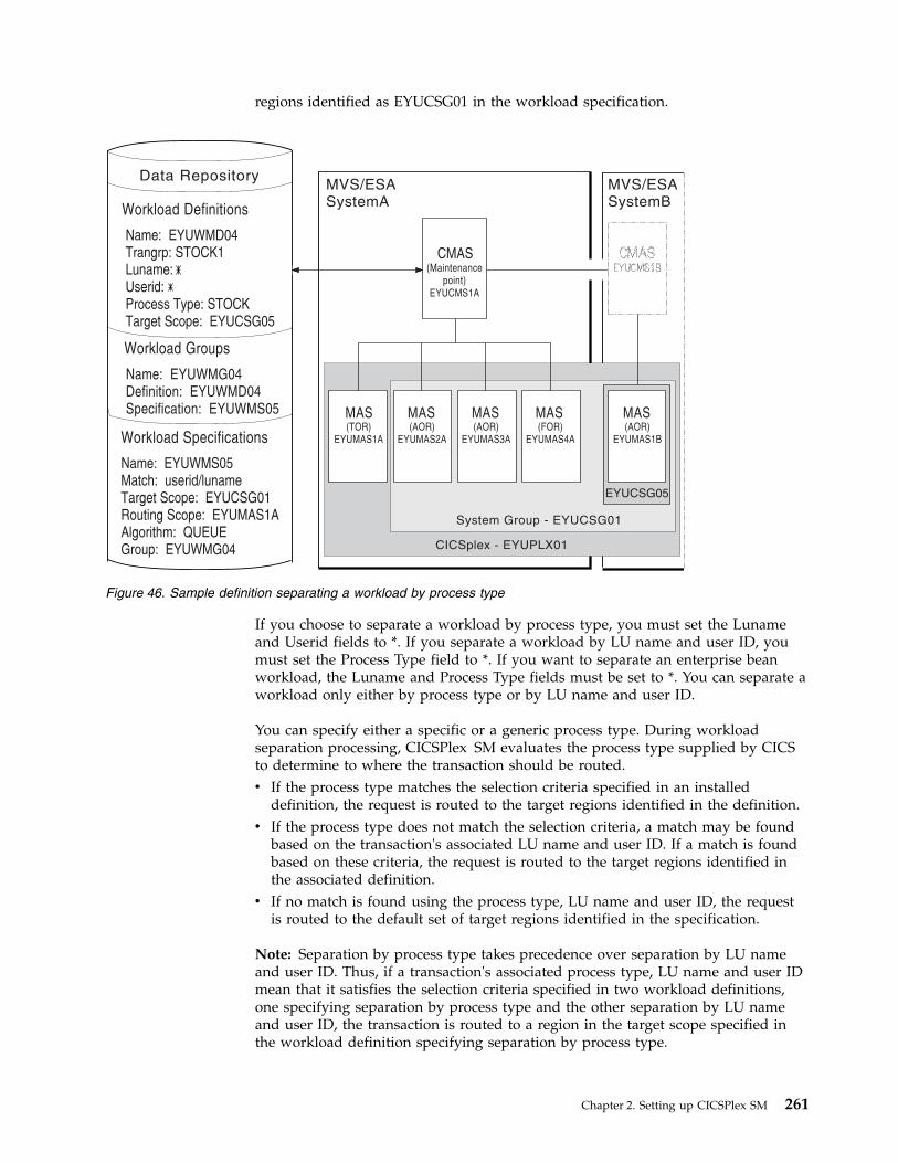
regions identified as EYUCSG01 in the workload specification.
If you choose to separate a workload by process type, you must set the Lunameand Userid fields to *. If you separate a workload by LU name and user ID, youmust set the Process Type field to *. If you want to separate an enterprise beanworkload, the Luname and Process Type fields must be set to *. You can separate aworkload only either by process type or by LU name and user ID.
You can specify either a specific or a generic process type. During workloadseparation processing, CICSPlex SM evaluates the process type supplied by CICSto determine to where the transaction should be routed.v If the process type matches the selection criteria specified in an installed
definition, the request is routed to the target regions identified in the definition.v If the process type does not match the selection criteria, a match may be found
based on the transaction's associated LU name and user ID. If a match is foundbased on these criteria, the request is routed to the target regions identified inthe associated definition.
v If no match is found using the process type, LU name and user ID, the requestis routed to the default set of target regions identified in the specification.
Note: Separation by process type takes precedence over separation by LU nameand user ID. Thus, if a transaction's associated process type, LU name and user IDmean that it satisfies the selection criteria specified in two workload definitions,one specifying separation by process type and the other separation by LU nameand user ID, the transaction is routed to a region in the target scope specified inthe workload definition specifying separation by process type.
Workload Definitions
Name: EYUWMD04Trangrp: STOCK1Luname:Userid:Process Type: STOCKTarget Scope: EYUCSG05
Workload Groups
Name: EYUWMG04Definition: EYUWMD04Specification: EYUWMS05
Data Repository
Workload Specifications
Name: EYUWMS05Match: userid/lunameTarget Scope: EYUCSG01Routing Scope: EYUMAS1AAlgorithm: QUEUEGroup: EYUWMG04 CICSplex - EYUPLX01
System Group - EYUCSG01
MVS/ESASystemB
MVS/ESASystemA
(TOR)EYUMAS1A
(AOR)EYUMAS2A
(AOR)EYUMAS3A
(FOR)EYUMAS4A
MAS MAS MAS MAS
(Maintenancepoint)
EYUCMS1A
CMAS
EYUCSG05
(AOR)EYUMAS1B
MAS
Figure 46. Sample definition separating a workload by process type
Chapter 2. Setting up CICSPlex SM 261
Separating by transaction:
You can also separate the work in a workload based on the transactionsthemselves. For example, you might want all occurrences of payroll-relatedtransactions initiated from terminals in an accounting department to be routed to aspecific set of target regions for processing.
Figure 47 on page 263 illustrates how you might separate the work in a workloadbased on transaction identifiers. In this case, if the user and terminal namesassociated with any transaction identified in transaction group EYUWMT01 beginwith SM and NET, respectively, the transaction is routed to the target regionsidentified as EYUCSG05. If the transaction identifier, user name, or terminal namedoes not match the criteria, the transaction is routed to the default target regionsidentified as EYUCSG01.
During workload processing, CICSPlex SM evaluates the transaction identifiersupplied by CICS to determine which transaction group to use.v If the transaction is defined to a transaction group, CICSPlex SM notes whether
the match key for that group is USERID or LUNAME.v If the transaction is not part of a transaction group, CICSPlex SM uses the match
key from the default transaction group for the specification. The match key isthe value specified with the associated specification. For additional information,see Transaction group definitions - TRANGRP.
CICSPlex SM uses the match key value to establish the order in which theterminal and user names associated with the transaction are to be evaluated. Theevaluation is used to determine where the transaction should be directed:v If the terminal and user names associated with the transaction match the
selection criteria specified in an installed workload definition, the request isrouted to the target regions identified in that definition.
v If the terminal and user names do not match the selection criteria, the request isrouted to the default set of target regions identified in the workloadspecification.
After determining the appropriate set of target regions, one is selected based onthe status of the active target regions in that set.
Note: If you are adding new transaction codes to a transaction group, or removingtransaction codes from a transaction group, you do not need to discard the WLMdefinition that refers to the transaction group if no other attributes of thetransaction group are being changed. New transaction codes added to a transactiongroup can be dynamically activated within an active workload by reinstalling theWLM definition that refers to the transaction group.A transaction (a DTRINGRP object) can be associated with one parent transactiongroup (TRANGRP) only, regardless of any parent workload association andirrespective of whether the transaction group is in active use or not. Changes at thetransaction group level, and at the WLM definition (WLMDEF) level, can bedynamically activated without terminating an active workload. Only changes at theWLM specification (WLMSPEC) level normally require an active workload to beterminated.
262 CICS TS for z/OS: CICSPlex SM Concepts and Planning

Separating Link3270 bridge workloads:
Link3270 bridge workloads can be separated by user ID, LU name, and transactiongroup.
For Link3270 bridge workloads the LU name can be produced in three differentways:1. It can be supplied by the user in the BRIH-NETNAME parameter on the
Link3270 call.2. It can be generated randomly by the Link3270 bridge facility.3. The CICS autoinstall user replaceable program can be used in conjunction with
either of the other two methods to accept, reject or modify the supplied orgenerated NETNAME.
You can separate Link3270 bridge workloads by LU name only if you are usingmethods 1 or 3 of those listed, so that the LU name is known in advance. If youare using the method 2, the LU name is not known in advance and cannot be usedfor workload separation.
To separate by the bridge facility NETNAME and not the name associated with theclient program that started the Link3270 bridge, you must modify the EYU9WRAMmodule. You can use the CICS API commands EXEC CICS ASSIGN USERID() and
CICSplex - EYUPLX01
System Group - EYUCSG01
MVS/ESASystemB
MVS/ESASystemA
(TOR)EYUMAS1A
(AOR)EYUMAS2A
(AOR)EYUMAS3A
(FOR)EYUMAS4A
MAS MAS MAS MAS
(Maintenancepoint)
EYUCMS1A
CMAS
EYUCSG05
(AOR)EYUMAS1B
MAS
Transaction Groups
Workload Definitions
Name: EYUWMD02Trangrp: EYUWMT01Luname: NETUserid: SMProcess Type:Target Scope: EYUCSG05
Workload Groups
Name: EYUWMG02Definition: EYUWMD02Specification: EYUWMS03
Name: EYUWMT01Match: luname/useridTranid: PAY1, PAY2,
INV1, INV2
Workload Specifications
Name: EYUWMS03Match: userid/lunameTarget Scope: EYUCSG01Routing Scope: EYUMAS1AAlgorithm: QUEUEGroup: EYUWMG02
Data Repository
Figure 47. Sample definition separating a workload by transaction
Chapter 2. Setting up CICSPlex SM 263

EXEC CICS ASSIGN BRFACILITY NETNAME() to assign the user ID and LU name. Youcan use the NETNAME returned from the INQUIRE BRFACILITY() command ratherthan the NETNAME passed via the DFHDYPDS commarea parameterDYRNETNM to separate the workload.
For more information about Link3270 bridge facility definitions, see Overview ofCICS external interfaces.
Taking affinity relations into considerationAn affinity is a relationship that you define between two or more transactions forthe duration, or lifetime, of that relationship.
When an affinity relationship exists between transactions, those transactions mustbe processed by the same target region. You can use affinities to route transactionsfrom one or more requesting regions to a specific target region based on the rulesapplying to a particular combination of an affinity relation and lifetime. For a listof affinity relation and lifetime values, see Affinity relations and affinity lifetimes.
When multiple CMASs in the CICSplex manage affinities for the workload, andone of these CMASs is brought down and the local MASs stay up, the workloadbecomes frozen. When the workload is frozen, it cannot be changed, however thecurrent workload remains active.
When a CMAS is down, and you have any of the following affinity life times andaffinity relationships, a new affinity instance cannot be created, and the transactioncannot be routed to the target MAS associated with the affinity, because the localTORs cannot be informed of the workload changes while the workload is frozen.
Affinity relation Affinity lifetime
BAPPL v SYSTEM
v PERMANENT
v ACTIVITY
v PROCESS
GLOBAL v SYSTEM
v PERMANENT
LOCKED v UOW
LUNAME v SYSTEM
v PERMANENT
USERID v SYSTEM
v PERMANENT
When the CMAS is brought back up and reconnects to the MASs, the workload isunfrozen and is able to be changed.
You can use the IBM CICS Interdependency Analyzer for z/OS to detect existingaffinities between transactions and between BTS processes and activities. Theoutput from the Reporter component of that utility can be used as input to theCICSPlex SM batched repository-update facility. For more information, see CICSInterdependency Analyzer for z/OS.
264 CICS TS for z/OS: CICSPlex SM Concepts and Planning

Note: You cannot use CICS Interdependency Analyzer to detect affinities betweennon-terminal-related EXEC CICS START commands, and between DPLs that arenot associated with either a user ID or a terminal ID. For these request types, youshould try to remove or avoid all affinities, and ensure that your applications canhonor any remaining affinities.
CICS BTS considerations:
Although BTS itself does not introduce any affinities, and discouragesprogramming techniques that do, it does support existing code that may introduceaffinities.
You must define such affinities to workload management. It is particularlyimportant to specify each affinity's lifetime. Failure to do this may restrictunnecessarily the workload management routing options.
It is important to note that a given activity can be run both synchronously andasynchronously. Workload management is only able to honor invocations that aremade asynchronously. Furthermore, you are strongly encouraged not to createthese affinities, particularly activity and process affinities, because these affinitiesare synchronized across the BTS-set. This could have serious performance impactson your systems.
You should also note that, with CICSPlex SM, the longest time that an affinity canbe maintained is while a CMAS involved in the workload is active; that is, anaffinity of PERMANENT. If there is a total system failure, or a planned shutdown,affinities will be lost, but activities in CICS will be recovered from the BTS RLSdata set.
Link3270 bridge considerations:
For Link3270 bridge transactions, affinities are managed by CICS and not byCICSPlex SM. Transaction affinity relation and lifetime fields in the workloadmanagement views should be left blank.
Adding affinities into a workload:
For non-Link3270 bridge transactions, affinities are managed by CICSPlex SMTransaction affinity relation and lifetime fields in the workload managementviews. You specify these fields to isolate transactions to particular systems and todefine affinity types and lifetimes.
Figure 48 on page 266 illustrates how you might separate the work in a workloadbased on transaction identifiers and then associate an affinity relation and lifetimewith those transactions. With this example, the first occurrence of a transactionnamed PAY1, where the associated terminal and user names are NET1 and SMITH,respectively, is directed to the appropriate target region within the set of targetregions identified as EYUCSG05. The specific target region receiving thetransaction and the affinity relation and lifetime associated with the transactiongroup to which PAY1 belongs are noted. All subsequent occurrences of anytransaction in the transaction group that meet the terminal and user name criteriaare directed to the same target region for the designated period of time.
Note: If you do not specify a default affinity relation and lifetime, then you canuse the same workload specification for workload routing and separation.
Chapter 2. Setting up CICSPlex SM 265

Note: During workload processing, CICSPlex SM evaluates the transactionidentifier supplied by CICS to determine which transaction group to use.v If the transaction is defined to a transaction group, CICSPlex SM notes the
match key for that group.v If the transaction is not part of a transaction group, CICSPlex SM uses the match
key from the default transaction group for the workload specification.
CICSPlex SM uses this value to establish the order in which the terminal and usernames associated with the transaction are to be evaluated. The evaluation is todetermine where the transaction is to be directed:v If the terminal and user names associated with the transaction match the
selection criteria specified in an installed workload definition, CICSPlex SMchecks to see if an affinity relation and lifetime are associated with thetransaction group.– When an affinity relation and lifetime are associated with the transaction
group:- If it is the first occurrence, CICSPlex SM notes the affinity relation and
lifetime. Based on target region availability, CICSPlex SM then selects atarget region and directs the transaction to it.
- If it is not the first occurrence, CICSPlex SM routes the transaction to thepreviously selected target region. As long as the affinity relation and
Transaction Groups
Workload Definitions
Workload Groups
Workload Specifications
Name: EYUWMT01Match: luname/useridAffinity: USERIDLifetime: SIGNONTranid: PAY1, PAY2
INV1, INV2
Name: EYUWMD03Trangrp: EYUWMT01Luname: NET #Userid: SM #Process Type: #Target Scope: EYUCSG05Group: EYUWMG03
Name: EYUWMG03Definition: EYUWMD03Specification: EYUWMS04
Name: EYUWMS04Match: userid/lunameAffinity: USERIDLifetime: SystemTarget Scope: EYUCSG01Routing Scope: EYUMAS1AAlgorithm: QUEUEGroup: EYUWMG03
CMAS(Maintenance
point)EYUCMS1A
CMASEYUCMS1B
MAS(TOR)
EYUMAS1A
MAS(AOR)
EYUMAS2A
MAS(AOR)
EYUMAS3A
MAS(FOR)
EYUMAS4A
MAS(AOR)
EYUMAS1B
EYUCSG05
System Group - EYUCSG01
CICSplex - EYUPLX01
Data Repository MVSSYSTEM A
MVSSYSTEM B
Figure 48. Sample definition adding transaction affinity to a workload
266 CICS TS for z/OS: CICSPlex SM Concepts and Planning

lifetime are applicable, subsequent occurrences of any transaction in thetransaction group are directed to the same target region.
– When no affinity relation and lifetime are associated with the transactiongroup, the transaction is routed to the most appropriate target region in thedesignated set of target regions.
v If the terminal and user names do not match the selection criteria, thetransaction is routed to the default set of target regions identified in theworkload specification. One is selected based on the status of the active targetregions in that set.
Note: When transactions in a series of terminal-initiated transactions are associatedwith separate transaction groups, affinities for each transaction group follow therules defined for that transaction group.
Abend probabilities and workload managementCICSPlex SM can evaluate the health and the activity (or load) of each regionidentified by the target scope. CICSPlex SM uses this information with theacceptable abend load threshold value (ABENDTHRESH) and the acceptable levelof abend probability value (ABENDCRIT) that you provide when definingtransaction groups to CICSPlex SM, in determining to which target region atransaction is routed.
In CICSPlex SM, the abend probability for transactions that are associated with atransaction group is calculated either for each transaction individually or for theentire group.v If the transaction is associated with a transaction group that either has no
defined affinity relation and lifetime, or uses the default values defined in aworkload specification, the abend probability is calculated individually for thattransaction.
v If the transaction is associated with a transaction group that has a definedaffinity relation and lifetime, the abend probability for that transaction iscalculated for the entire group of transactions.
The abend probability for transactions that are not associated with a transactiongroup is derived from the default abend probability values defined in theworkload specification.
The acceptable abend load threshold value (ABENDTHRESH) and the acceptablelevel of abend probability value (ABENDCRIT) that you provide apply to both thehealth and the load of a potential target region. You can specify these values eitherin the workload specification (default rule) or a transaction group definition(associated with a specific rule) by using WUI or CICS® TS Explorer, as shown inthe following table:
Table 14. Fields for ABENDTHRESH and ABENDCRIT in WUI and CICS TS Explorer
Parameters WUI CICS Explorer
ABENDTHRESH Acceptable abend loadthreshold
Threshold
ABENDCRIT Acceptable level of abendprobability
Critical
When an unhandled abend occurs in a target region:
Chapter 2. Setting up CICSPlex SM 267

v For the transaction, or transactions associated with the transaction, that abends,the abend probability percentage is set to 100% in the target region, which isimmediately considered unhealthy as a result.
v CICSPlex SM then gradually reduces the abend probability percentage. Whenthe abend probability percentage is below the specified acceptable level of abendprobability (ABENDCRIT) yet above the specified acceptable abend loadthreshold (ABENDTHRESH), the target region is no longer consideredunhealthy. However, the region's perceived load is doubled, making itproportionally less attractive as a target for routing than other equally loadedregions.
v CICSPlex SM continues to reduce the abend probability percentage. When theabend probability percentage falls below the acceptable abend load threshold,the target region's load is set to normal, making it equally attractive as a targetfor routing as other equally loaded target regions.
v If a further unhandled abend occurs at any point, the process is reset and theabend probability is recalculated from the initial starting point, where the regionis considered unhealthy.
v If the target region is considered unhealthy, CICSPlex SM attempts to avoidrouting the transaction to that target region. However, if there is no healthiertarget region, the transaction might be routed to that target region.
Notes:
1. Abend probabilities are taken into account only if you are using the dynamicrouting exit DTRPGM. Abend probabilities are not considered if you are usingthe distributed routing exit DSRTPGM.
2. If an affinity is active, all subsequent transactions are routed to the same targetregion for as long as the affinity remains active, regardless of its abendprobability.
3. If a transaction abends in a target region where the EXEC CICS HANDLEABENDcommand is active, CICSPlex SM does not receive the information thatthe abend has occurred. Therefore, CICSPlex SM cannot take such abends intoaccount when calculating the abend probability for the transaction in that targetregion. The abend probability might stay low in this situation, even thoughabends occurred.
4. If an application avoids making calls to resource managers because it knowsthe connection to the resource manager is not active, or it processes an errorreturn code as a result of the connection being unavailable, and proceeds toissue an error message and return normally rather than abend, it could deludethe workload manager into routing more work to the CICS region. Thissituation is called the “storm drain effect”. See Avoiding the storm drain effect.
Activating workload managementTo activate workload management, you must associate a workload specificationwith the CICS system and update the CICS system to use the dynamic routing ordistributed routing program.
Before you begin
You must identify the CICS systems that you want to use for dynamic routing ofyour workloads. The requesting regions are where the requests are initiated, forexample a terminal-owning region; the routing regions decided where to routetransactions or programs; the target regions are where the transaction or programrun, for example an application-owning region. Together, the requesting, routing,
268 CICS TS for z/OS: CICSPlex SM Concepts and Planning

and target regions form a single entity within which you can route work.
About this task
For more information about dynamic routing, see “Dynamic routing withCICSPlex SM” on page 270.
Procedure1. Associate a workload specification with the CICS system, using the WLMSPEC
view, as described in Associating a CICS system or system group with aworkload specification.
2. Identify the dynamic routing program EYU9XLOP to the CICS systems actingas requesting regions and any routing region:v If the CICS system is not active, you can make workload management
processing available the next time the CICS system starts up. Set theDTRPGM system initialization parameter in the requesting region and in anytarget region that acts as a routing region:
DTRPGM=EYU9XLOP
For non-terminal-related EXEC CICS START commands, BTS activities, and forall regions in a logical server, set the DSRTPGM system initializationparameter in the region that initiates the request and in all potential targetregions:
DSRTPGM=EYU9XLOP
v If the CICS system is active, you can use the CICS regions detailed view, asdescribed in CICS regions - CICSRGN, to set the name of the dynamicrouting program and the distributed routing program.
3. Activate workload management for the CICS system. You can do this using thefollowing views:v Use the CICS system definitions view to change the CICS system definition
in the data repository.v Use the MASs known to CICSplex view to temporarily activate workload
management for an active CICS system.
Results
When either the first routing region associated with a CICSplex is started, or youuse the MASs known to CICSplex detailed view to activate workloadmanagement for the first routing region in a CICSplex, the appropriate workloadspecifications are installed automatically. All CMASs involved in managing theCICSplex are also notified. All workload definitions and transaction groups,associated with the specification by workload groups, are also installedautomatically. As long as the CICS system remains active, additional workloaddefinitions can be installed manually in the CICS system.
Note: When a requesting region associated with a CICSplex, and defined witheither DTRPGM=EYU9XLOP or DSRTPGM=EYU9XLOP, is starting, it connects toits target CMAS and workload management is activated. However, if the targetCMAS is not active when the routing region is starting, any transactions initiatedfrom that routing region and processed by the EYU9XLOP program waitindefinitely until the CMAS becomes active and the requesting region fullyconnects to it. After the requesting region connects to the CMAS and workloadmanagement is activated, the CMAS can become inactive and workloadmanagement remains active.
Chapter 2. Setting up CICSPlex SM 269

When a workload is active, subsequent changes to workload definitions andtransaction groups are noted in the data repository. To include these changes in anactive workload, you must use action commands to install or discard them.
Installed workload definitions become active immediately and remain active aslong as the workload is active or until you discard them. To verify that thedefinition is installed in the workload and that all of the CMASs involved inmanaging the CICSplex using that workload know about the definition, you canuse the Active workload definitions view.
How long a workload remains active depends on the affinity lifetime associatedwith the workload:v When an affinity lifetime of PERMANENT is in effect, the workload remains
active as long as any CMAS involved in managing the workload is active.v When any other affinity lifetime, or no affinity lifetime, is associated with the
workload, the workload remains active as long as any CICS system that isassociated with that workload remains connected to a CMAS that manages theCICSplex to which that CICS system belongs.
What to do next
When workload management is active, do not attempt to deactivate it while anyworkloads are active. When CICSPlex SM is routing or separating the work in aworkload, unpredictable results might occur if you attempt to deactivate workloadmanagement. Unacceptable results occur if you attempt this action when affinityrelations are associated with active workloads. For details, see Discarding an activetransaction from a workload.
Configuring dynamic routingYou can define a transaction to CICS as either local or remote. Local transactionsalways run in the requesting region; remote transactions can be routed to any CICSsystem connected to the routing region. Routing of remote transactions can bedynamic, static, or ATI-controlled.
Dynamic routing with CICSPlex SMUse CICSPlex SM to select the most appropriate target region for the execution of adynamic transaction by using the workload management facility.
When a remote transaction is initiated, the CICS relay program is invoked. TheCICS relay program links to the dynamic routing program EYU9XLOP. EYU9XLOPcreates the environment necessary for CICSPlex SM-based dynamic routing andsets up the CICSPlex SM runtime environment. You must specify EYU9XLOP inthe system initialization table (SIT) parameter.v For static routing, ATI, and dynamic routing, set the DTRPGM SIT parameter
that is associated with the requesting region that initiates the transaction:DTRPGM=EYU9XLOP
Any target region that is also to act as a routing region must also specifyDTRPGM in the SIT and must be set up as a routing region as described inAssociating a CICS system or system group with a workload specification.
vFor non-terminal-related EXEC CICS START commands, BTS activities, orenterprise beans, specify the system initialization parameter DSRTPGM=EYU9XLOP in
270 CICS TS for z/OS: CICSPlex SM Concepts and Planning

the requesting region that initiates the request. Also set DSRTPGM=EYU9XLOP in allpotential target regions if the DYROPTER field in the communications area orcontainer for the routing program (mapped by the DFHDYPDS copybook) is tobe set to Y.If you use CICSPlex SM to route non-terminal-related EXEC CICS STARTcommands, the DYROPTER field is always set to Y. You must therefore alwaysspecify the system initialization parameter DSRTPGM=EYU9XLOP and ensure that thetarget region is part of the workload. Failing to ensure that the target region isdefined to the workload results in the started transaction waiting for theworkload to become available and the transaction hangs.
Note: If the target region is not going to be set up as a routing region, then do notspecify EYU9XLOP in the DTRPGM and DSTRPGM SIT parameters. Specifyingthis parameter causes an endless loop for routed transactions in EYU9XLOPwaiting for the workload, which never arrives.
CICS notifies EYU9XLOP of all routing requests. These requests are as follows:v Route selection, route selection error, and transaction termination.v For BTS (all supported releases of CICS), transaction initiation, transaction
abend, and routing attempt complete.v For non-terminal EXEC CICS START requests (all supported releases of CICS),
transaction initiation, transaction abend, and routing attempt complete.
When CICS links to EYU9XLOP, it passes the CICS communication areaDFHDYPDS to it.
Control then passes to the CICSPlex SM workload management facilities.CICSPlex SM initializes the workload management MAS agent code and engagesits routing action process. This process is called internally if any of the followingconditions are true:v The EYU9WRAM user-replaceable module is not defined to CICSv EYU9WRAM is defined to CICS, but is not availablev EYU9WRAM is defined to CICS, is available, and the load module is the
assembly language version of the module as distributed with CICSPlex SM.
The internal routing action process produces the same results as running theassembly language version of EYU9WRAM as it is distributed with CICSPlex SM.If no additional dynamic routing control is required at your enterprise, the internalprocess provides better performance.
The EYU9WRAM module, or its equivalent internal process, receives theCICSPlex SM-based communication area EYURWCOM. An entry for EYU9WRAMis added to the CICS system definition file, DFHCSD, for each CICS system duringinstallation. As distributed with CICSPlex SM, EYU9WRAM drives CICSPlex SMworkload management processing. EYU9WRAM does this by first obtaining theappropriate list of target region candidates, based on the transaction group, andthe terminal ID, LU-name, user ID, or process type. Then, EYU9WRAM selects atarget region from the list of candidates.
Chapter 2. Setting up CICSPlex SM 271

CICS release requirements for dynamic routingHere are CICS release requirements for regions involved in dynamic routing.
Table 15. Release requirements for regions involved in dynamic routing.
Releaserequirementfor: Routing regions Target regions
Requestingregions
Dynamictransactionrouting
Any supported release ofCICS
Any supported release ofCICS
-
EXEC CICSSTARTcommands
Any supported release ofCICS
Any supported release ofCICS
Any supportedrelease of CICS
CICS BusinessTransactionServices (BTS)
Any supported release ofCICS
Any supported release ofCICS
Any supportedrelease of CICS
Distributedprogram link(DPL)
Any supported release ofCICS
Any supported release ofCICS
-
Enterprisebeans
CICS Transaction Serverfor z/OS, Version 4Release 2 or earlier
CICS Transaction Serverfor z/OS, Version 4Release 2 or earlier
-
Link3270 bridge Any supported release ofCICS
Any supported release ofCICS
-
Sample source programs and copy booksFollowing installation, the module EYU9WRAM is loaded into CICSPlex SM.
It is an assembler-language, command-level program; its corresponding copy booksare:
EYURWCOMDefines the communication area
EYURWCODDefines literals for EYURWCOM
EYURWSVEDefines each element of a target region scope list
EYURWSVDDefines literals for EYURWSVE
To assist you in your customization effort, sample source programs and copybooks for assembler, C, COBOL, and PL/I are distributed with CICSPlex SM.Copy books are located in language-specific libraries. All samples programs arelocated in the SEYUSAMP library. The names of the sample programs and copybooks, and the CICSPlex SM libraries in which they can be found are listed inTable 16.
Table 16. Table 1. Sample programs and copy booksLanguage Member name Alias LibraryAssembler:Program EYUAWRAM EYU9WRAM SEYUSAMPCopybook 1 EYUAWCOM EYURWCOM SEYUMACCopybook 2 EYUAWCOD EYURWCOD SEYUMAC
272 CICS TS for z/OS: CICSPlex SM Concepts and Planning

Table 16. Table 1. Sample programs and copy books (continued)Language Member name Alias LibraryCopybook 3 EYUAWSVE EYURWSVE SEYUMACCopybook 4 EYUAWSVD EYURWSVD SEYUMACCOBOL:Program EYULWRAM EYU9WRAM SEYUSAMPCopybook 1 EYULWCOM EYURWCOM SEYUCOBCopybook 2 EYULWCOD EYURWCOD SEYUCOBCopybook 3 EYULWSVE EYURWSVE SEYUCOBCopybook 4 EYULWSVD EYURWSVD SEYUCOBPL/I:Program EYUPWRAM EYU9WRAM SEYUSAMPCopybook 1 EYUPWCOM EYURWCOM SEYUPL1Copybook 2 EYUPWCOD EYURWCOD SEYUPL1Copybook 3 EYUPWSVE EYURWSVE SEYUPL1Copybook 4 EYUPWSVD EYURWSVD SEYUPL1C:Program EYUCWRAM EYU9WRAM SEYUSAMPCopybook 1 EYUCWCOM EYURWCOM SEYUC370Copybook 2 EYUCWCOD EYURWCOD SEYUC370Copybook 3 EYUCWSVE EYURWSVE SEYUC370Copybook 4 EYUCWSVD EYURWSVD SEYUC370
Implementing optimized dynamic workload routingCICSPlex SM provides dynamic workload management for CICS. CICSPlex SM canaugment its workload management decisions using current status informationposted directly from CICS by using a region status (RS) server.
Before you begin
Full workload optimization can be achieved with sysplex optimized workloadrouting. However, this capability requires that all workload regions are migrated toCICS TS for z/OS, Version 4.1 and later.
Sysplex optimized workload routing takes place automatically when all workloadregions are running at CICS TS 4.1 and later, and when a region status (RS) serveris started in the same z/OS image as each region in the workload in the CICSplex.
You can mix CICS TS for z/OS, Version 4.1 and later regions in a workload withregions at a level earlier than CICS TS 4.1. However, workloads will run in anonoptimized state.
For details about sysplex optimized workload routing, see Sysplex optimizedworkload routing overview.
About this task
To optimize workload routing in a sysplex, you must configure and monitor aregion status (RS) server, as part of a coupling facility data table. For instructions,see Setting up and running a region status server and Security for coupling facilitydata tables.
Chapter 2. Setting up CICSPlex SM 273

Procedure
In the CICSplex definition, you can set the coupling facility (CF) tuning parametersfor the region status (RS) server, which provide sysplex optimized workloadrouting. You define and modify CICSplexes using the EYUSTARTCPLEXDEF viewset. The coupling facility (CF) tuning parameters are in the CPLEXDEF detail view.
Note: You can also modify the default region status (RS) pool name that will beused by all regions in the CICSplex. When you do not to use the default nameDFHRSTAT, you must change the name before starting any other regions in theCICSplex. CICSPlex SM will not prevent you from changing the pool name whilethe CICSplex is active. If you make a change while the CICSplex is active, allCMAS and MAS regions in the CICSplex must be restarted as soon as possible.Failure to do so can result in inconsistent data in the CICSPlex SM WLM viewsand WLM optimization is deactivated until all the regions in the CICSplex arerestarted.Configuring for workload routingYou can set the following configurations:v How long region status data is cached by a routing region before requesting a
refresh for sysplex optimized workload routing. See Region status server, readinterval parameter (READRS).
v How often the coupling facility is updated with task throughput data for sysplexoptimized workload routing. See Region status server, update frequencyparameter (UPDATERS).
v The task load range that triggers workload distribution updates to the couplingfacility (CF) during periods of low throughput. See Region status server,bottom-tier parameter (BOTRSUPD).
v A task load top tier that controls the workload when the region is close to theMAXTASK (MXT) setting during periods of high throughput. See Region statusserver, top-tier parameter (TOPRSUPD).
Viewing optimization status
v For a workload, view the Active workloads list view in the CICSPlex SM WebUser Interface (WUI).
v For a CICS region, view the Routing regions or Target regions views located inthe Active workloads menu.For more information, see “Optimization status” on page 278.
Region status server, read interval parameter (READRS):
You use the region status server read interval parameter in the CPLEXDEF,CSYSDEF, and MAS views to control how long region status data is cached by arouting region before requesting a refresh for sysplex optimized workload routing.
READRS={200|number}
In a workload running in optimized mode, the READRS value specifies theminimum interval, in milliseconds, between refreshes of a target region status froma CICS region status (RS) server. These refresh requests are issued by a routingregion that is evaluating a target region for a dynamic routing request.
Note: You should only change the READRS value after considering the impact thatthe change might have on your workload and coupling facility throughput.
274 CICS TS for z/OS: CICSPlex SM Concepts and Planning

The value range is from 0 - 2000:v A value of 0 means that a routing region requests a status update of a target
region on every occasion that it examines the status of the target region.v Values from 1 - 2000 specify the minimum time interval that must expire before
the status of a target region can be refreshed.
A low interval value means that the RS server is polled more often for a statusupdate. For workloads in QUEUE mode, this low value results in a smoother taskload spread across the CICS regions in the workload target scope, assuming all otherhealth and link factors are equal. However, the utilization of the RS server iscorrespondingly increased, which might result in higher utilization of your z/OScoupling facility.
The default value of the READRS parameter is 200 milliseconds.
The value specified in the EYUSTARTCPLEXDEF view set sets the read interval atthe CICSplex level. However, you can override the interval at the CICS definitionlevel to allow fine tuning of the value on an individual CICS target region basis.
You specify both the UPDATERS and the READRS parameters at the CICSplexdefinition (CPLEXDEF) level to establish default values for all regions in theCICSplex. You can override these values at the CICS system definition (CSYSDEF)level or at the MAS agent runtime (MAS) level.
At the CICS definition level, the value for UPDATERS and READRS is INHERIT, so thatthe values are adopted from the CICS system definition. By changing these valuesto explicit numeric values, the CICS system adopts the values specified on eachsuccessive restart. To implement a change to a running CICS region, the valuesmust be applied using the MAS base tables or view sets. When the target region isrestarted, it reemploys the specification from its CSYSDEF.
Region status server, update frequency parameter (UPDATERS):
You use the region status server update frequency parameter in the CPLEXDEF,CSYSDEF, and MAS views to control how often the coupling facility is updatedwith task throughput data for sysplex optimized workload routing.
UPDATERS={15|number}
In a workload running in optimized mode, the UPDATERS value indicates thefrequency that the CICS region status (RS) server is called to modify the value ofthe task load in a target CICS region. This value is the default frequency value forall target CICS regions in the current CICSplex definition.
Note: You should only change the UPDATERS value after considering the impact thatthe change might have on your workload and coupling facility throughput.
The value range is from 0 - 25:v A value of 0 means that the RS server is not notified of any task load count
changes, because the optimized workload function for target regions in thisCICSplex is not enabled.
Note: A value of 0 does not suppress optimization of the workload routingfunction; a value of 0 suppresses only the target region RS domain broadcastingprocess.
Chapter 2. Setting up CICSPlex SM 275

v Values from 1 - 25 are applied as an arithmetic percentage to the MAXTASKSsetting for a target. The resulting task count value is used as a numericthreshold to drive an update call to the RS server.
Specifying a value of zero effectively disables the optimized routing function forthe target regions. For an optimized routing decision to be made, both the routerand target must be in optimized mode.
For example, with a MAXTASKS setting of 120, and the UPDATERS set to 20, theRS server is called to update the WLM load count when the task count for a targetregion changes between these numbers of tasks:v 23 and 24 tasks (20% of 120)v 47 and 48 tasks (40% of 120)v 71 and 72 tasks (60% of 120)v 95 and 96 tasks (80% of 120)v 119 and 120 tasks (100% of 120)
The RS server is updated when the task load for a target region increments ordecrements across these boundaries.
If you set the UPDATERS parameter to a low value, the frequency of updates to theRS server increases across the task load range. For workloads in QUEUE mode,this low value results in a smoother task load spread across the target CICSregions in the workload scope, assuming all other health and link factors are equal.However, the utilization of the RS server is correspondingly increased, whichmight result in higher utilization of your z/OS coupling facility.
The default value for the UPDATERS parameter is 15.
The value specified in the EYUSTARTCPLEXDEF view set sets the update intervalat the CICSplex level. However, you can override the interval at the CICSdefinition level to allow fine tuning of the value on an individual CICS targetregion basis.
You specify both the UPDATERS and the READRS parameters at the CICSplexdefinition (CPLEXDEF) level to establish default values for all target regions in theCICSplex. You can override these values at the CICS system definition (CSYSDEF)level or at the MAS agent runtime (MAS) level.
At the CICS definition level, the value for UPDATERS and READRS is INHERIT, so thatthe values are adopted from the CICS system definition. By changing these valuesto explicit numeric values, the CICS system adopts the values specified on eachsuccessive restart. To implement a change to a running CICS region, the valuesmust be applied using the MAS base tables or view sets. When the target region isrestarted, it uses the specification from its CSYSDEF.
Region status server, bottom-tier parameter (BOTRSUPD):
You use the region status server bottom-tier tuning parameter in the CPLEXDEF,CSYSDEF, and MAS views to control the workload distribution updates to thecoupling facility (CF) during periods of low throughput.
276 CICS TS for z/OS: CICSPlex SM Concepts and Planning

BOTRSUPD={1|number}
For sysplex optimized workloads, the BOTRSUPD value is converted from a task loadpercentage to a real task count. That count is used to define the bottom-tier taskload range, from zero up to this value.
Note: You should only change the BOTRSUPD value after considering the impact thatthe change might have on your workload and coupling facility throughput.
The value range is from 1 - 25. When the task load for a region falls within thisrange, the task load is then broadcast to the coupling facility (CF) for every changein the task load. When the load reaches this value, the RS server update frequencytask rules are activated.
The default value of the BOTRSUPD parameter is 1%.
Change this value only after considering the impact that the change might have onyour workload and coupling facility throughput. The BOTRSUPD parameter providesa smoother distribution of the workload during periods of low throughput. Whenyour CICSplex consists of many target regions and you increase this value toomuch, you risk overloading the CF with update requests, which can result indegraded WLM and general z/OS subsystem performance.
When you need to modify the BOTRSUPD value, ensure that you monitor theperformance of your coupling facility and WLM throughput capabilities for at leastseveral days after modification.
Region status server, top-tier parameter (TOPRSUPD):
You use the region status server top-tier tuning parameter in the CPLEXDEF,CSYSDEF, and MAS views. It controls the workload when the workloadmanagement (WLM) max task health indicator is switched off for a target region,to limit updates to the coupling facility (CF) when the region is close to theMAXTASK (MXT) setting during periods of high throughput.
TOPRSUPD={5|number}
For sysplex optimized workloads, the TOPRSUPD value is converted from a task loadpercentage to a real task count. That count is subtracted from the MAXTASKS valuefor the region to determine the top-tier task load range.
Note: You should only change the TOPRSUPD value after considering the impact thatthe change might have on your workload and coupling facility throughput.
The value range is from 1 - 25. The value is applied as an arithmetic percentage tothe MAXTASKS setting for a region. The task count value is then subtracted from theMAXTASKS setting for the region to establish a task load top tier. When the task loadin a region runs up to its MAXTASKS limit, the task load must then drop back belowthis value before the MAXTASKS state for the region is switched off and broadcast tothe coupling facility.
The default value of the TOPRSUPD parameter is 5%.
Change the TOPRSUPD value only after considering the impact that the change mighthave on your workload and coupling facility throughput. When you increase thisvalue too much, you see a workload batching effect in the upper load range of the
Chapter 2. Setting up CICSPlex SM 277

workload. When you decrease the value too much, the upper-tier batching effect isreduced, but updates to the coupling facility can be significantly increased.
When you need to modify the TOPRSUPD value, ensure that you monitor theperformance of your coupling facility and WLM throughput capabilities for at leastseveral days after modification.
Optimization status:
You can use the Active workloads list view in the CICSPlex SM Web User Interface(WUI) to view the status of workloads.
Optimization status of the workload
You can use the Active workloads list view in the CICSPlex SM Web User Interface(WUI) to view the status of each workload active in the CICSplex.
The Optimization status attribute reports the sysplex optimization status of thecurrent workload. The value is a combination of all of the workload routeroptimization statuses and all of the workload target optimization statuses.
These values are possible:v ACTIVE: All targets and routers in the workload are running in optimized
workload state.v PARTIAL: At least one target and one router are running in optimized workload
mode. Use the Active routing regions and Active target regions hyperlinks todetermine which regions are not running in optimized state.
v INACTIVE: The workload is not running in an optimized state, for one or moreof the following reasons:– No routing regions in the workload are running in an optimized state.– No target regions in the workload are running in an optimized state.– No regions in the workload are running in an optimized state.– The workload is designated as being nonoptimized by specifying a value of 0
for the RS server update frequency on the CICSplex definition or on all targetCICS system definitions for this workload.
Optimization status for a CICS region
You can use the Routing regions or Target regions views located in the Activeworkloads menu to view the optimization status for the region.
The Optimization status attribute reports the status of the current target regionfor the optimized workload routing function.
These values are possible:v ACTIVE: This target region is running in an optimized workload state.v INACTIVE: This region can run in an optimized workload state; however, it is
not currently optimized for one or more of the following reasons:– The region has no connection to an RS server.– The region is connected to an RS server; however, the server cannot connect
to the z/OS coupling facility.
278 CICS TS for z/OS: CICSPlex SM Concepts and Planning

– The optimization enablement setting for the region is set to Disabled. Theenablement setting for the region must be set to Enabled before any optimizedrouting functions can be activated.
Note: You can reset the optimization enablement setting in the CICS systemdefinition view to change the value in preparation for the next region startup.The enablement setting can also be changed in an active region using theMAS view, but will revert to the setting in the CICS system definition whenthe region is restarted.
– The RS server update frequency value for this region is 0, which means thatthe optimization capabilities for this region when acting as a routing targetare not enabled.
Note: You can set the UPDATERS value to 0 for regions that are used asdynamic routers only. Setting this value to 0 prevents the region from makingunnecessary region status broadcasts to the Region Status (RS) server.
v N_A: The target region is not at a CICS release that supports region statusrecording. Only nonoptimized WLM routing decisions can be made.
Nonoptimized workload routing:
In releases before CICS TS for z/OS, Version 4.1, for nonoptimized workloadmanagement, and when a coupling facility is not available, workload routing ismanaged by CICSPlex SM Workload Manager using a data space owned by aCMAS to share cross-region load and status data.
Every CMAS manages a single WLM data space that it shares with every userCICS region (MAS) that it directly manages. When the CMAS initializes, it verifiesand formats the data space with the structures necessary for all workloadsassociated with the CICS regions that it manages. When the user CICS regionsbegin routing dynamic traffic, the state of those CICS regions is recorded in thisdata space. Every 15 seconds, the CICSPLex SM agent in the user CICS regiondetermines the task count at that time and reports to its owning CMAS. TheCMAS updates the load count in the target region descriptor of its WLM dataspace and broadcasts that value to other CMASs participating in workloadsassociated with the user CICS region.
In an environment in which all user CICS regions are managed by the sameCMAS, all routing and target regions refer to the same physical structures in theWLM data space. Dynamic routing decisions are based on the most current loaddata for a potential routing target region. A routing decision is based on acombination of factors. For details, see Factors that contribute to dynamicworkload routing decisions.
Workloads are spread across multiple z/OS images, so additional CMASs areconfigured to manage the user CICS regions on the disparate LPARs. Each WLMdata space must maintain a complete set of structures to describe every CICSregion in the workload, not just the CICS regions for which each CMAS isresponsible. The WLM data space owned by each CMAS must be periodicallysynchronized with the WLM data spaces owned by other CMASs that areparticipating in the workload. This synchronization occurs every 15 seconds fromthe MASs to their CMASs, and then out to all other CMASs in the workload.
The behavior of CICSPlex SM is different for DTRPGM and DSRTPGM requests:
Chapter 2. Setting up CICSPlex SM 279

v For DTRPGM requests, the routing region calls, from CICS, to decide if thetarget regions are synchronized with the execution of the request at the selectedtarget, which is then followed by a call back from CICS on completion of thedynamic request. This call allows the router to increment the task load countbefore informing CICS of the target region system ID, and also to decrement thecount on completion of the request.
v For DSRTPGM requests, the routing region calls, from CICS, to decide if targetsare not synchronized with the selected target. Typically, these dynamic requestsare asynchronous CICS starts. The router has no notification of when the routedtransaction starts or finishes. Because of a lack of notification, CICSPlex SMstipulates that a DSRTPGM target region must also have the workloadassociated with the region, which transforms the targets into logical routingregions. This call allows the CICSPlex SM routing processes to determine thatthey are being called at the DSRTPGM target and, therefore, allows the task loadcount to be adjusted at transaction start and finish.
CICSPlex SM routing regions count the dynamic transaction throughput in aCICSplex, introducing an additional problem in that transactions started locally onthe target regions remain unaccountable by the routing regions until a heartbeatoccurs. The router transaction counts are not accurately synchronized until twoheartbeats have occurred, the first to increment the count, and the second todecrement it again. This discrepancy, however, is not considered as severe as whena router and target are managed by different CMASs.
For multiple CMASs, the router regions evaluate status data for a target region asdescribed in its local WLM data space. If that target region is managed by adifferent CMAS to that owned by the router, status data describing that targetregion can be up to 15 seconds old. For DTRPGM requests, this latency does nothave a severe effect. For DSRTPGM requests, however, the effect can be significant,particularly when the workload throughput increases. The effect is known asworkload batching.
For more information, see “Workload batching.”
Workload batching:
Workload batching occurs in heavily used workloads in multiple CMASenvironments, where dynamic distributed (DSRTPGM) routing requests are beingprocessed.
A target region and its routing regions can be managed by different CMASes. Thisis always the case when the router runs in a different LPAR to the targets. In thisscenario, the router is using a different descriptor structure to evaluate the targetstatus from the real descriptor structure employed by the target itself.
The target descriptor reviewed by the router is synchronized with the realdescriptor at 15-second intervals by the CICSPlex SM heartbeat. The task count forthe target region, as seen by the router, is refreshed at the same time. During a15-second heartbeat interval, the router regards the target as being relatively busy,or relatively quiet, when compared to other potential target regions in theworkload. Therefore, for that 15-second duration, the router continues to divertwork towards, or away from, the target, depending on how busy it seems to be,because the current task count in the target is not seen to change until the nextheartbeat. This routing, based on the previous status, can make the target verybusy or unused. The router reacts to this situation by more actively routing worktowards, or away from, the target, so the batching cycle continues. This state
280 CICS TS for z/OS: CICSPlex SM Concepts and Planning

continues until activity in the workload throughput declines, which settles downthe batching cycle until the throughput activity increases.
If you are monitoring the task load across the CICSplex, you see some regionsrunning at their MAXTASKS limit and being continually given dynamically routedtraffic, and others remain unused. A snapshot taken 15 seconds later might show areversal of utilization; the busy regions might be idle and the idle regions mightnow be at the MAXTASKS limit.
When you start your region status servers and optimize workloads, the effects ofworkload batching are removed.
Modifying dynamic routingYou can customize CICSPlex SM workload management processing by modifyingthe module EYU9WRAM.
EYU9WRAM uses the CICSPlex SM dynamic routing application programminginterface (API), which is a special-purpose, call-level interface that provides themechanism needed to request workload management actions. All calls areconstructed using standard CALL statements. The CALL statement generates thelinkage between the EYU9WRAM module and the CICSPlex SM WorkloadManager component. The format of the CALL statement is shown here:
CALL WAPIENPT(DA_TOKEN,function)
where:
DA_TOKENIdentifies the dynamic routing API token supplied via the EYURWCOMcommunication area. This token is used by EYU9WAPI and must not bealtered.
functionIs the function to be performed, specified as:
SM_SCOPEReturns a list of eligible target regions.
SM_BALANCESelects a target region from the list of eligible target regions.
SM_ROUTERoutes a transaction to a specific target region.
SM_CREAFFCreates an affinity.
SM_DELAFFDeletes an active affinity.
You can use SM_SCOPE and SM_BALANCE together to obtain a list of targetregions and then select the target region to which a transaction is to be routed.
If you know that a transaction is always to be directed to a specific target region,you can use just SM_ROUTE.
As distributed, EYU9WRAM issues SM_SCOPE and SM_BALANCE calls. It doesnot include any SM_ROUTE calls. It includes unexecuted calls to SM_CREAFF andSM_DELAFF. You can modify the program to issue these calls.
Chapter 2. Setting up CICSPlex SM 281

Although all the examples use the assembler language form of the dynamicrouting API verbs, you can also use these verbs in programs written in C, COBOL,and PL/I. Sample programs distributed with CICSPlex SM contain examples of theCALL statements for each of these languages.
Note: If you are modifying dynamic routing, be aware that:v If they are not set, the values for application context are either zero (for the
version) or nulls/low-values (for platform, application, and operation).v String fields are padded with nulls, not spaces.
Important: As distributed, EYU9WRAM handles the workload routing andseparation established via the workload management definitions by using the APIverbs. Any changes you make to EYU9WRAM, therefore, might adversely impactthe CICSPlex SM workload management facilities. For example, if you do not useSM_SCOPE, SM_BALANCE, or SM_ROUTE, each transaction occurrence is routedto the default target region identified when the transaction was defined to CICS.Thus, all CICSPlex SM workload management definitions are bypassed.
Nondynamic transaction considerations:
You do not have to include any calls through the API if a transaction is staticallyrouted or is started by ATI. In these cases, the target region cannot be changed.The routing function is route notify. The route notify function is intended to notifythe EYU9WRAM program that such a transaction is being routed.
If you do include any of these functions, the following occurs:v An SM_SCOPE call returns a single entry in the SCOP_VECT. The entry is the
target region associated with the statically defined transaction when it wasdefined, or with the destination specified on the EXEC CICS START commandfor ATI transactions.
v An SM_BALANCE call selects the target region associated with the transactionwhen it was defined to CICS. The CICSPlex SM Workload Manager will notcreate any affinity for the transaction.
v An SM_ROUTE call returns an exception response.
When EYU9WRAM is called for:v Notification, any existing affinity relations are ignored and none are created.v Route selection error, any existing affinity relations are ignored and none are
created. In addition, the EYU9WRAM program as delivered will write a terminalmessage and terminate.
v Routing attempt complete, for CICS BTS transactions only. Any existing affinitiesare ignored. Any dynamic routing API function call results in a bad response.See “Non-terminal-related STARTs and CICS BTS considerations” on page 283.
v Transaction initiation, for CICS BTS transactions only. Any existing affinities areignored. Any dynamic routing API function call results in a bad response. See“Non-terminal-related STARTs and CICS BTS considerations” on page 283.
v Transaction termination, any existing affinities are ignored. Any dynamic routingAPI function call results in an error response.
v Transaction abend, any existing affinities are ignored. Any dynamic routing APIfunction call results in an error response.
282 CICS TS for z/OS: CICSPlex SM Concepts and Planning

Non-terminal-related STARTs and CICS BTS considerations:
When routing a transaction associated with either a CICS BTS activity or anon-terminal-related EXEC CICS START comand, the routing program, identifiedin the DSRTPGM SIT parameter, is invoked for both static and dynamic routing.
In the case of statically routed transactions, the EYU9WRAM program cannot alterthe target region; see “Nondynamic transaction considerations” on page 282. In thecase of dynamically routed transactions, the EYU9WRAM program may alter thetarget region; see “Selecting a target region from a set of target regions.” However,in both cases, the EYU9WRAM program is invoked only for:v In the requesting region:
– Notification– Route selection– Route selection error– Route attempt complete
v In the target region:– Transaction initiation– Transaction termination– Transaction abend
For details of the function of route initiation, see Dynamically routing DPLrequests.
Selecting a target region from a set of target regions:
As distributed, EYU9WRAM uses SM_SCOPE and SM_BALANCE to select a targetregion from the list of target regions defined for a transaction. The options that youset affect the way that the target region is chosen.v SM_SCOPE returns a list of target regions for the current transaction occurrence.
The target regions are those that are explicitly or implicitly associated with therequesting region by a workload specification.
v SM_BALANCE selects a target region from the list of candidate target regionsreturned by SM_SCOPE.
After an SM_SCOPE or SM_BALANCE call, the result of the operation is indicatedin the response and reason fields of the EYURWCOM communication area.
Actions during route selection
A dynamic route selection occurs when a transaction or program is scheduled forrouting.v When SM_SCOPE is issued, the EYURWCOM communication area Scope Vector
pointer is updated with the address of the target region scope list descriptionarea, SCOP_VECT. Also, the element count field is updated to contain the countof elements in the scope vector. Each element in the scope vector identifies acandidate target region and indicates its current status.During SM_BALANCE processing, the target region appearing first in theordered list is selected for routing, unless the scope vector element EYURWSVEis marked ignore.
v When no affinity is associated with the current transaction occurrence, anSM_SCOPE call sorts the SCOP_VECT elements so that the target region that isthe best candidate is placed first in the list.
Chapter 2. Setting up CICSPlex SM 283

During SM_BALANCE processing, the APPLID and SYSID of the most suitabletarget region are placed in the fields WCOM_SEL_AOR andWCOM_SEL_SYSID, respectively. Typically, this will be the first target regionrepresented in the scope vector. However, if the EYU9WRAM program hasmarked the WSVE-IGNORE field on some of the SCOP_VECT elements todenote that the target region is to be ignored, the first target region in the scopevector that is not marked to be ignored will be selected.
Note:
1. If the transaction identifier and the ids of the terminal and user associatedwith that transaction match a transaction group to which an affinity isdefined, the affinity is made active during SM_BALANCE processing.
2. With DPL, you can update the transaction id before the SM_SCOPE call.v When an affinity is associated with the current transaction occurrence, an
SM_SCOPE call normally causes only the target region with which the affinityexists to be identified in SCOP_VECT. An SM_BALANCE call then selects thattarget region. If the target region is not available for routing, the SM_BALANCEfunction will set a warning indicator. It will not attempt to select another targetregion.
v If the transaction is defined as a DTRTRAN, the EYURWCOM communicationarea will contain indicators denoting that the transaction is a DTRTRAN andthat it will not be rejected by the Workload Manager. Processing is generallyidentical to the normal, non-DTRTRAN, case. Issuing SM_SCOPE returns aSCOP_VECT. Issuing SM_BALANCE selects a target region.The EYU9WRAM module might opt to reject the transaction before issuing theSM_SCOPE call. In this case, the Workload Manager returns to CICS with thereject indicator set to Y in the DFHDYPDS communication area. The sampleEYU9WRAM program causes a DTRTRAN transaction to be rejected only if thetransaction identifier is all blanks.
Actions during notification
Notification occurs when a static transaction or ATI transaction is being scheduledfor routing.v For statically routable transactions, ATI transactions, and BTS static routing
requests, issuing SM_SCOPE causes the scope vector to contain a single targetregion. This is the target region associated with the transaction.
Actions during routing attempt complete
None, but you can tidy up and release any resources at this stage.
Actions during route selection error
A route selection error call occurs if the CICS link between the requesting regionand target region is not available or is not defined.v When no affinity is active: issue SM_SCOPE again. The candidate target regions
identified by the SCOP_VECT it returns will not include the target region thatcaused the error. You can then use SM_BALANCE to select a new target region.
v When affinity became active as a result of the previous route selection:– If the lifetime associated with the affinity is PERMANENT, SYSTEM,
ACTIVITY, or PROCESS, the target region causing the error will be includedin scope list returned by SM_SCOPE. SM_BALANCE is required by affinity
284 CICS TS for z/OS: CICSPlex SM Concepts and Planning

rules to select that target region. It also returns a warning to EYU9WRAM.EYU9WRAM should then notify the user that an error has occurred.
– If the lifetime associated with the affinity is SIGNON, LOGON, DELIMIT, orPCONV, the active affinity status is removed before control returns toEYU9WRAM. When you reissue SM_SCOPE, the target region causing theerror will not be included in the scope list. If the workload specification isdefined with Create Affinity YES for the transaction group, EYU9WRAM isnotified that an affinity is defined and will be activated when you issueSM_BALANCE.
v When affinity was activated by a previous transaction instance, and you issueSM_SCOPE again, the scope list returned contains the previously selected targetregion. Since SM_BALANCE is required by affinity rules to select that targetregion, a warning is returned to EYU9WRAM. EYU9WRAM should then notifythe user that an error has occurred.
Actions during transaction termination
Transaction termination occurs when a transaction has terminated normally.v EYU9WRAM should release any resources it may have acquired.v Issuing SM_SCOPE or SM_BALANCE or SM_ROUTE causes an exception
response to be returned.
Actions during transaction abend
Transaction abend occurs when a transaction has terminated abnormally.v EYU9WRAM should release any resources it may have acquired.v Issuing SM_SCOPE or SM_BALANCE or SM_ROUTE causes an exception
response to be returned.
Actions during transaction initiation
Transaction initiation occurs when a CICS BTS-related transaction, or an enterprisebean-related transaction, has been routed to the target region. No specific action istaken. The call is issued for information purposes only.
Selecting a specific target region:
SM_ROUTE requests that a specific target region is selected for routing. UseSM_ROUTE when you have application- or data-dependent requirements forexplicit routing. For example, you might want to route a transaction associatedwith a specific user ID to a specific target region.
After an SM_ROUTE call, the result of the operation is stored in the response andreason fields of the EYURWCOM communication area.
A sample SM_ROUTE call is show here:CALL WAPIENPT(DA_TOKEN,SM_ROUTE)
DA_TOKEN identifies the dynamic routing API token supplied via theEYURWCOM communication area. This token is used by EYU9WAPI and must notbe altered.
Chapter 2. Setting up CICSPlex SM 285

Actions during route selection
The actions during route selection are:v If there is only one connection between a requesting region and the target
region, you can supply either the SYSID or the APPLID of the target region(CICSPlex SM will determine the appropriate, corresponding ID). Place theAPPLID in the WCOM_SEL_AOR field of the EYURWCOM communicationarea. Place the SYSID in the WCOM_SEL_SYSID field.If there are multiple connections between a requesting region and the targetregion, supply both the SYSID and the APPLID, as described previously, toensure that the correct target region is selected. Note that when both the SYSIDand APPLID are supplied, they are not validated.The target region need not be defined to CICSPlex SM. The affinity status is notchecked. Thus, no affinity is established as a result of this call and, if an affinitywas in effect, it is ignored.
v Issuing SM_ROUTE during Route Notify processing causes an exceptionresponse to be returned.
Actions during routing attempt complete
None, but you can tidy up and release any resources at this stage.
Actions during route selection error
The EYU9WRAM program may issue a message and terminate. You may thenissue SM_ROUTE again specifying a different target region, or issue SM_SCOPEand SM_BALANCE.
Actions during transaction termination
v EYU9WRAM should terminate any resources it may have acquired.v Calling any API function causes an exception response to be returned.
Actions during transaction abend
v Calling any API function causes an exception response to be returned.
Actions during transaction initiation
At transaction initiation:v EYU9WRAM should terminate any resources it may have acquired.v Calling any API function causes an exception response to be returned.
Creating an affinity:
You can use SM_CREAFF to create an affinity if one does not already exist in thetransaction group established for the transaction.
The transaction group must be defined with an affinity type and lifetime. Theaffinity created will have the same affinity type and lifetime as defined in thetransaction group.
You should review “Affinity considerations” on page 287 before usingSM_CREAFF.
286 CICS TS for z/OS: CICSPlex SM Concepts and Planning
Before calling SM_CREAFF, you must first call SM_SCOPE to obtain a scope list.SM_CREAFF will not create an affinity to an target region that is not in the scopelist. In addition, you should set the EYUWRCOM communication area fieldsWCOM_SEL_AOR and WCOM_SEL_SYSID to the APPLID and SYSID,respectively, of the target region for which you want the affinity created.
EYU9WRAM contains a fragment of unexecuted code that you can use as atemplate for implementing the SM_CREAFF function.
The SM_CREAFF function cannot be called during:v Route terminationv Route abendv Route notifyv Route initiatev Route complete
Deleting an affinity:
You can use SM_DELAFF to delete an active affinity.
You should review “Affinity considerations” before using SM_DELAFF.
Before calling SM_DELAFF, you must first call SM_SCOPE to obtain a scope list.The WCOM_AFF_STAT field in the EYURWCOM communication area contains avalue indicating whether an affinity is active or committed. An active affinity canbe deleted using SM_DELAFF. A committed affinity has a lifetime of SYSTEM orPERMANENT and cannot be deleted using SM_DELAFF.
EYU9WRAM contains a fragment of unexecuted code that you can use as atemplate for implementing the SM_DELAFF API function.
The SM_DELAFF function cannot be called during:v Route notifyv Route initiatev Route complete
Affinity considerations:
When you define an affinity, you must specify its lifetime. The affinity normallypersists until its specified lifetime expires.
You can define one of the following types of lifetime:
ActivityExpires when the CICS BTS activity ends
DelimitExpires when the PCONV mode of the transaction is END
Logon Expires when the terminal user logs off.
Pconv Expires when a transaction uses EXEC CICS RETURN specifying noNEXTTRANSID or the PCONV mode of the transaction is END.
CICS does not support pseudoconversations for APPC (LUTYPE6.2)devices.
Chapter 2. Setting up CICSPlex SM 287

PermanentExpires when the workload of which the target region is a part terminates
ProcessExpires when the CICS BTS process ends
SignonExpires when the terminal user signs off.
SystemExpires when the target region terminates
UOW Expires when the unit of work associated with the transaction ends. Theunit of work ends either when a CICS SYNCPOINT or ROLLBACK requestis run, or when the originating task terminates.
There are circumstances when SM_SCOPE generates a scope list containing asingle affinity target region, but the target region is not available for routing. Thishappens when:v The target region is down.v The CICS link to the target region is down.v The target region is currently active but it was shutdown and restarted after the
affinity was created.
In these cases, the EYU9WRAM default processing issues a terminal messageindicating that the affinity target region is not available and causes the transactionto terminate. If the affinity lifetime is PCONV (pseudoconversation), CICSPlex SMautomatically deletes the affinity because it has expired (there is noNEXTTRANSID). However, the default EYU9WRAM processing does not deleteany other affinities because the characteristics of the actual affinity to the targetregion are unknown. For example, a LOGON affinity may involve the use of theTCTUA to pass information to the target region. If the affinity is deleted when thetarget region is not available, the next transaction for the transaction group wouldcause a new target region to be selected. The transaction might fail upon using theTCTUA contents when routed to the new target region.
The sample EYU9WRAM program, which implements the default processing,contains a subroutine that checks on affinity status after a call to SM_SCOPE.When an affinity is active to an target region, but not committed, and the affinitytarget region status is not OK, the subroutine sends a message to the terminal userand then exits so that the EYU9WRAM program terminates. The subroutinecontains an unexecuted code fragment that can be used to delete the affinity usingthe SM_DELAFF call. Before the unexecuted code fragment is a series of tests forthe affinity lifetime of the active affinity. One or more of the branches can bechanged to jump to the code fragment. The code fragment itself deletes the affinity,issues a message, and then returns so that the EYU9WRAM program exits, therebycausing the transaction to terminate. This processing can be modified so that theaffinity is deleted, no message is issued, and the subroutine exits causing themainline process to reexecute the SM_SCOPE call. In that case, a new set of targetregions is received for use by SM_BALANCE.
The same subroutine also contains an unexecuted code fragment that can beenabled to create an affinity. In this case, the subroutine has determined that anaffinity is defined but not active. It then checks the WCOM_AFF_AUTO indicatorto determine whether CICSPlex SM should automatically create affinities duringSM_BALANCE. The subroutine exits normally no matter what the answer is. Youcan enable the SM_CREAFF fragment in order to cause an affinity to be created.
288 CICS TS for z/OS: CICSPlex SM Concepts and Planning

The SM_CREAFF call may be used regardless of whether WCOM_AFF_AUTOdoes or does not indicate the automatic creation of affinities duringSM_BALANCE. The SM_CREAFF call can therefore be used to:v Create an affinity when CICSPlex SM will not.v Create an affinity to a target region that CICSPlex SM would ordinarily not
select.
The SM_CREAFF code fragment creates an affinity to the target region thatappears first in the scope list returned by SM_SCOPE.
The following fields in the EYURWCOM communication area provide informationregarding CICSPlex SM affinity processing.v WCOM_AFF_STATv WCOM_AFFAOR_STATv WCOM_AFF_TYPEv WCOM_AFF_LIFEv WCOM_AFF_AUTOv WCOM_WORK_NAMEv WCOM_TGRP_NAME
CICSPlex SM data areasThe EYU9WRAM program uses two data areas, communication area EYURWCOMand scope vector element EYURWSVE.
Literals for EYURWCOM are defined in EYURWCOD and literals for EYURWSVEare defined in EYURWSVD.
The names of the copy books that you can use to map these data areas areidentified in Sample programs and copy books.
The scope vector element, EYURWSVE, contains information about the individualtarget regions associated with the list of candidate target regions returned bySM_SCOPE.
Creating a user-replacement module for EYU9WRAMYou can use the sample procedures provided in CICSTS55.CPSM.SEYUPROC tocreate replacement modules for EYU9WRAM.
The procedure members are as follows:
Assembler EYUEITALC EYUEITDLPL/I EYUEITPLCOBOL EYUEITVL
1. Copy these procedures to a cataloged system procedure library. You can use thesamples in Sample user-replacement modules.
2. Use the JCL samples to run the procedure and create the replacement modulefor EYU9WRAM. Replace the lower case values shown in the sample JCL withthe appropriate values for your site. Also, you cannot use the CICSPlex SM APIin EYU9WRAM.
Requesting additional dynamic routing supportThis section contains Product-sensitive Programming Interface Information.
Chapter 2. Setting up CICSPlex SM 289

You can access the CICSPlex SM workload management facilities directly from anapplication program.
Note: If you are running CICS Transaction Server for OS/390® Version 1 Release 3and later, it is recommended that you use the CICSPlex SM-supplied programEYU9XLOP for all your dynamic routing requirements. You need the informationin this section only if you want to continue to use this function during migrationto CICS Transaction Server for OS/390 Version 1 Release 3.
If your routing regions are CICS Transaction Server for OS/390 Version 1 Release 3and later, or if you are using CICS BTS or enterprise beans, you do not need theinformation in this section. You should use the distributed routing facilitiesdescribed in “Dynamic routing with CICSPlex SM” on page 270.
To write such a program, you should be familiar with:v The interface between the CICS relay program and the defined dynamic routing
program.v CICSPlex SM workload management processing, as described in Overview of
CICSPlex SM workload management.v The CICSPlex SM workload management routing action module, EYU9WRAM,
as described in “Dynamic routing with CICSPlex SM” on page 270.
The primary method of invoking CICSPlex SM workload management is bydefining module EYU9XLOP to CICS as the dynamic routing program. This causesEYU9XLOP to be invoked by the CICS relay program, allowing CICSPlex SMworkload management to make a routing decision about each work request thatcan be sent to another CICS system.
If necessary, CICSPlex SM workload management can be invoked directly from anapplication program, without going through the CICS relay program. For CICSreleases prior to CICS Transaction Server for OS/390 Version 1 Release 3, you canuse CICSPlex SM Workload Management to determine the best target region for adistributed program link (DPL) from a requesting region. The application programyou write must follow certain guidelines:v The program must run in a CICS system that is defined and running as a
routing region. You cannot access CICSPlex SM workload management from atarget region.
v The program must issue its INIT and TERM calls from the same task.CICSPlex SM expects the program to imitate the processing done by the CICSrelay program, which always calls at route initiation and route termination.
Note: Accessing workload management through a program that issues an EXECCICS START command is not recommended with an asynchronous transactionstart. Furthermore, EXEC CICS START commands that are not related with either aterminal or a user should not be used for transactions that have affinityrelationships, as those relationships cannot be correctly resolved using thisinterface.
Accessing workload management from a program using a dynamic program loadis not supported. CICSPlex SM workload management uses the CICS applicationprogramming interface to gather information about the current environment inwhich it is running. Due to DPL restrictions some of that information is notavailable, and unpredictable results may occur.
290 CICS TS for z/OS: CICSPlex SM Concepts and Planning

In order to make a routing decision, CICSPlex SM workload management needscertain information that is normally supplied by the CICS relay program. The CICSrelay program derives the information from data available to CICS for the instanceof the transaction being relayed. When you invoke CICSPlex SM workloadmanagement directly, you need to provide this information, includingterminal-oriented data and the equivalent of a transaction name to identify thework to be routed.
How to start CICSPlex SM workload managementTo start the CICSPlex SM workload management facilities, use an EXEC CICSLINK command, specifying EYU9XLOP as the program and identifyingEYURWTRA as the communication area.
The format of the command is:EXEC CICS LINK
PROGRAM(EYU9XLOP)COMMAREA(EYURWTRA)LENGTH(=AL2(WTRA_LENGTH))
Much of the data normally passed from the CICS relay program to the dynamicrouting program in the DFHDYPDS communication area must be generated byyour program and passed to CICSPlex SM workload management. Other data thatis normally derived by CICSPlex SM workload management from a transaction-and terminal-oriented environment must also be provided by your program. Theassembler copy book EYURWTRA provides a map of the communication area to bepassed to CICSPlex SM workload management.
The corresponding copy books and the CICSPlex SM libraries in which they canbe found are:
Language Member name Library
Assembler EYUAWTRA SEYUMACCOBOL EYULWTRA SEYUCOBPL/I EYUPWTRA SEYUPL1C EYUCWTRA SEYUC370
Before invoking CICSPlex SM workload management, you must initialize theEYURWTRA communication area.
For a list of the possible response and reason code values that can be returned inWTRA_API_RESP and WTRA_API_REAS, refer to the assembler copy bookmember EYURWCOD.
Processing considerationsAfter CICSPlex SM workload management processing, the WTRA_RESPONSEfield contains a return code of either zero (0) or 8.
If the return code is 0, WTRA_SYSID contains the SYSID of the selected targetregion, and WTRA_APPLID contains its APPLID. With that information, you canproceed to route the unit of work to the target region.
If the return code is 8, you should inspect the WTRA_API_RESP andWTRA_API_REAS fields for more information. These fields contain the lastresponse and reason codes returned to the CICSPlex SM workload managementrouting action module (EYU9WRAM). In most cases, the response and reason
Chapter 2. Setting up CICSPlex SM 291

codes describe what caused CICSPlex SM workload management to generate thereturn code of 8. Based on that information, you can decide how to proceed.
In some cases, however, the WTRA_RESPONSE field may contain a return code of8, while the WTRA_API_RESP and WTRA_API_REAS fields have not been set byCICSPlex SM workload management. In those cases, an error was detected beforeinvoking the routing action process. CICSPlex SM user trace records are written tothe CICS trace data set for those types of errors. When this happens, your programshould terminate processing.
When the return code is 8, you should also inspect the WTRA_OPTER field. If itsvalue is WTRA_CALLYES:1. Set the WTRA_FUNC field to WTRA_FUNCTRM for route termination.2. Reinvoke CICSPlex SM workload management.3. Terminate processing for the proposed unit of work.
If the WTRA_OPTER field contains a value of WTRA_CALLNO, terminate furtherprocessing for the proposed unit of work.
After the unit of work has completed in the target region, set the WTRA_FUNCfield according to how the unit of work completed. If the unit of work completedsuccessfully:1. Set the WTRA_FUNC field to WTRA_FUNCTRM for route termination.2. Optionally, set the WTRA_NEXTTRAN field to the ID of the next transaction to
be used in the process. If there is no next transaction, set the field to all blanks.3. Reinvoke CICSPlex SM workload management to request termination
processing for the transaction.
If the unit of work abended or generated an error that you consider abnormal:1. Set the WTRA_FUNC field to WTRA_FUNCABD to notify CICSPlex SM
workload management that the routed transaction abended.2. Reinvoke CICSPlex SM workload management to request abnormal
termination processing for the transaction.
Route error considerations:
After you receive the SYSID and APPLID of a target region, you can attempt toroute the unit of work to the target region.
However, the routing attempt may result in an error condition if the system isunavailable. When this happens, you should:1. Set the WTRA_FUNC field to WTRA_FUNCERR to indicate a routing error.2. Specify the reason for the error in the WTRA_ERR field.3. Reinvoke CICSPlex SM workload management.
CICSPlex SM workload management provides another target from the scope list, ifpossible. If no other systems are available, the WTRA_RESPONSE field is set to 8and the WTRA_API_RESP and WTRA_API_REAS fields describe the reason for thefailure. You may have to invoke CICSPlex SM workload management more thanonce for routing errors until you receive a valid target region.
292 CICS TS for z/OS: CICSPlex SM Concepts and Planning

Transaction affinity considerations:
If the WTRA_TRANID, WTRA_USERID and WTRA_LUNAME fields causeCICSPlex SM workload management to select a transaction group that includes anaffinity, the rules of transaction affinities are obeyed.
In this case, you should ensure that the WTRA_NEXTTRAN field is initializedwith the ID of the next transaction before calling the route termination function.
If your units of work, or any subset of them, have an affinity relation defined, becareful in how you define that affinity. Since your program cannot provideSIGNOFF or LOGOFF processing, an affinity lifetime of SIGNON or LOGON,though valid, may cause an affinity relation to be built that is not removed untileither the requesting region or the target region terminates.
The WTRA_NEXTTRAN field is most useful for pseudo-conversation affinities. Forthis affinity lifetime, CICSPlex SM workload management normally issues theEXEC CICS ASSIGN NEXTTRANSID command to retrieve the next transaction ID,if any, for the facility. Since that command is not available when CICSPlex SMworkload management is invoked by your program, it is your responsibility toprovide the ID of the next transaction.
For a description of CICSPlex SM workload management affinity processing, seeTaking affinity relations into consideration. For details on specifying affinityrelation and lifetime values, see Creating a transaction group.
Abend compensation considerations:
If the target region is running CICS TS, transactions initiated by your program canparticipate in abend compensation processing, provided that the activeCICSPlex SM workload specifies it.
You should note that, if the work requests are either non-terminal-related EXECCICS START commands, or BTS activities, the routing and target regions must bewithin the same MVS image for the routing region to detect that an abend hasoccurred.
Your program should notify CICSPlex SM workload management that a particularunit of work abended by specifying WTRA_FUNCABD in the WTRA_FUNC field.Then, if possible, CICSPlex SM workload management will tend to avoid selectingthe same target region for the transaction (or set of transactions, if an affinity isdefined) on subsequent route select functions.
For a description of CICSPlex SM workload management abend compensationprocessing, see Abend probabilities and workload management. For details onrequesting abend compensation, see Creating a workload specification.
CMAS availability considerations:
If your program issues an EXEC CICS LINK for the EYU9XLOP program, but therequesting region in which your program is running has not yet fully connected toits target CMAS, you see message EYUXL0020I, indicating that an ESSS connectionis in progress.
Your program waits indefinitely until the CMAS becomes available and therequesting region is joined to a workload. If you have connected successfully to the
Chapter 2. Setting up CICSPlex SM 293

CMAS and the MAS, but the CMAS has not installed any workload definitions tothe MAS, you see a message indicating that the requesting region is waiting for aworkload. You may need to set up and install workloads to rectify this situation.
Note: Once the requesting region has successfully connected to the CMAS, theCMAS can become inactive and workload management remains active.
Sample calling sequenceThis code example illustrates a sample calling sequence for a program that accessesCICSPlex SM workload management facilities. It is not intended to be used as asample program and is, therefore, not complete in every detail.*---------------------------------------------------------------------*
DFHEISTG , Define WorkareaWRK_WTRA DS CL(WTRA_LENGTH)
DS 0DWRK_UOWCOMM DS 0CWRK_UOW_RESP DS FWRK_UOWCOMM_L EQU *-WRK_UOWCOMM
COPY EYURWTRA Include DSECT to map WTRASRVPGM DFHEIENT EIBREG=R11,DATAREG=R13,CODEREG=R12
*---------------------------------------------------------------------** Initialize the WTRA COMMAREA. **---------------------------------------------------------------------*
LA R8,WRK_WTRA --> WTRAUSING EYURWTRA,R8 *** USING WTRA ***MVC WTRA_SLENGTH,=AL2(WTRA_LENGTH)
Set length of block.MVI WTRA_ARROW,C’>’ Set arrow.MVC WTRA_NAME,=C’EYURWTRA’ Set the name.MVI WTRA_BLANK,C’ ’ Set blank delimit.MVC WTRA_PGMNAME,=CL8’SRVPGM ’
Set program name.MVC WTRA_TERMID,=CL4’TRM1’ Set TermID.MVC WTRA_USERID,=CL8’USR1’ Set USERID.MVC WTRA_LUNAME(8),=CL8’.NET1’
Set LUNAME.MVC WTRA_TRANID,=CL8’TRN1’ Set TRANID.MVC WTRA_SYSID,=C’SYS1’ Set SYSID.MVC WTRA_APPLID,=C’APPLID1’ Set Applid.
** Set Application Context*
MVC WTRA_PLATFORM,=CL64’PLATFORM_1.0.0’MVC WTRA_APPLICATION,=CL64’APPLICATION_1.0.2’MVC WTRA_MAJORVER,=F’1’MVC WTRA_MINORVER,=F’1’MVC WTRA_MICROVER,=F’1’MVC WTRA_OPERATION,=CL64’PLEASE_ROUTE’MVI WTRA_FUNC,WTRA_FUNCSEL Set the Route Select Function.MVI WTRA_DYRTYPE,WTRA_DYRTYPE_DYN
*---------------------------------------------------------------------** Invoke the WLM MAS Agent for Route Select. **---------------------------------------------------------------------*ROUTE_SELECT DS 0H
BAS R5,LINK_WLM Go do it.CLC WTRA_RESPONSE,=F’0’ Call go OK?BNE CHECK_OPTER ..no.BAS R5,START_UOW Go Start the UOW.LTR R15,R15 Work Completed?BZ ROUTE_TERM ..yes.BP ROUTE_ABND UOW gave non zero return code.C R15,=F’-4’ SYSID error?BNE ROUTE_ABND ..no.
294 CICS TS for z/OS: CICSPlex SM Concepts and Planning
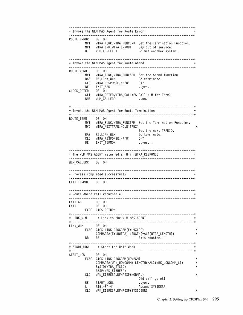
*---------------------------------------------------------------------** Invoke the WLM MAS Agent for Route Error. **---------------------------------------------------------------------*ROUTE_ERROR DS 0H
MVI WTRA_FUNC,WTRA_FUNCERR Set the Termination Function.MVI WTRA_ERR,WTRA_ERROUT Say out of service.B ROUTE_SELECT Go Get another system.
*---------------------------------------------------------------------** Invoke the WLM MAS Agent for Route Abend. **---------------------------------------------------------------------*ROUTE_ABND DS 0H
MVI WTRA_FUNC,WTRA_FUNCABD Set the Abend function.BAS R5,LINK_WLM Go terminate.CLC WTRA_RESPONSE,=F’0’ OK?BE EXIT_ABD ..yes.
CHECK_OPTER DS 0HCLI WTRA_OPTER,WTRA_CALLYES Call WLM for Term?BNE WLM_CALLERR ..no.
*---------------------------------------------------------------------** Invoke the WLM MAS Agent for Route Termination **---------------------------------------------------------------------*ROUTE_TERM DS 0H
MVI WTRA_FUNC,WTRA_FUNCTRM Set the Termination Function.MVC WTRA_NEXTTRAN,=CL8’TRN2’ X
Set the next TRANID.BAS R5,LINK_WLM Go terminate.CLC WTRA_RESPONSE,=F’0’ OK?BE EXIT_TERMOK ..yes. .
*---------------------------------------------------------------------** The WLM MAS AGENT returned an 8 in WTRA_RESPONSE **---------------------------------------------------------------------*WLM_CALLERR DS 0H
*---------------------------------------------------------------------** Process completed successfully **---------------------------------------------------------------------*EXIT_TERMOK DS 0H
*---------------------------------------------------------------------** Route Abend Call returned a 0 **---------------------------------------------------------------------*EXIT_ABD DS 0HEXIT DS 0H
EXEC CICS RETURN*---------------------------------------------------------------------** LINK_WLM : Link to the WLM MAS AGENT **---------------------------------------------------------------------*LINK_WLM DS 0H
EXEC CICS LINK PROGRAM(EYU9XLOP) XCOMMAREA(EYURWTRA) LENGTH(=AL2(WTRA_LENGTH)) X
BR R5 Exit routine.
*---------------------------------------------------------------------** START_UOW : Start the Unit Work. **---------------------------------------------------------------------*START_UOW DS 0H
EXEC CICS LINK PROGRAM(UOWPGM) XCOMMAREA(WRK_UOWCOMM) LENGTH(=AL2(WRK_UOWCOMM_L)) XSYSID(WTRA_SYSID) XRESP(WRK_EIBRESP)
CLC WRK_EIBRESP,DFHRESP(NORMAL) XDid call go ok?
BE START_UOWL ..yes.L R15,=F’-4’ Assume SYSIDERRCLC WRK_EIBRESP,DFHRESP(SYSIDERR) X
Chapter 2. Setting up CICSPlex SM 295

Is there one?BE START_UOWX ..yes.L R15,=F’-8’ Load Failure code.B START_UOWX Go exit.
START_UOWL DS 0HL R15,WORK_UOW_RESP Load Response Code.
START_UOWX DS 0HBR R5 Exit routine.
Routing program-link requests“Traditional” CICS-to-CICS distributed program link (DPL) calls, instigated byEXEC CICS LINK PROGRAM commands, can be daisy-chained from region toregion by defining the program as remote in each region except the last (server)region, where it is to execute.
Important: For detailed information about routing program-link requests, see CICSdistributed program link. This appendix is an overview of how program-linkrequests received from outside CICS can be routed to other regions.
The same applies to program-link requests received from outside CICS. Forexample, all of the following types of program-link request can be routed:v Calls received from:
– CICS Web support– The CICS Transaction Gateway
v Calls from external CICS interface (EXCI) client programsv External Call Interface (ECI) calls from any of the CICS Client workstation
productsv ONC/RPC calls.
Static routingA program-link request received from outside CICS can be statically routed to aremote CICS region by specifying the name of the remote region on theREMOTESYSTEM option of the installed program definition.
Dynamic routingA program-link request received from outside CICS can be dynamically routed bydefining the program to CICS as DYNAMIC(YES), and coding your dynamicrouting program to route the request.
296 CICS TS for z/OS: CICSPlex SM Concepts and Planning

Chapter 3. Administering resources with CICSPlex SM
You can manage all of your CICS and CICSPlex SM resources through any of thefollowing interfaces; the CICS Explorer, the CICS Management Client Interface(CMCI), a WUI view, or using the CICSPlex SM API.
Manage your resource definitions in the following ways:v Using the CMCI, which accepts HTTP requests from your application.v Using the CICS Explorer, which takes advantage of CMCI.v Using the CICSPlex SM Web User Interface (WUI).v Adding CICSPlex SM API commands directly to your application.
Managing and installing resources
Use Business Application Services (BAS) to manage and install CICS resources thatare stored on the CICSPlex SM data repository.
Use CSD to manage and install CICS resources that are stored on the CICS SystemDefinition (CSD) repository.
You must define a CSDGROUP for a CSD resource and a DEFVER for a BASresource.
Managing resources using Business Application Services (BAS)Business Applications Services is the component of CICSPlex SM that you use tomanage the CICS resource definition and installation process for businessapplications at your enterprise.
What is Business Application Services (BAS)?Business Application Services (BAS) is an alternative to resource definition online(RDO) that enables you to manage CICS resources in terms of the businessapplication to which they belong, rather than their physical location in theCICSplex.
A business application can be any set of resources that represent a meaningfulentity in your enterprise. Within the application, you can group together resourcesof a particular type and define the run-time characteristics of that group. Atrun-time, you can refine the selection of resources to be installed by using a filterexpression, and you can change the resource attributes by using an overrideexpression.
Limitations of RDORDO is the traditional CICS method of defining resources to CICS systems.
With RDO, resource definitions are tied to a single group and groups that areprocessed sequentially from a group list. Any duplicate definition found later inthe process overrides any earlier one. In addition, the very nature of the definitionsthat RDO requires and the extent to which they are available to multiple CICSsystems can prove limiting. RDO has several disadvantages in a CICSPlex SMenvironment:
© Copyright IBM Corp. 1989, 2018 297

v Resources are assigned to groups that are assigned to specified CICS systems.v Resource definitions have to be duplicated across CICS systems, unless the CSD
is shared.v Each end of every communications link has to be defined explicitly.
BAS conceptsBAS enables you to view and manage your resources in terms of their use in yourbusiness, and independently of their physical location.
This section introduces the basic concepts of the BAS function.
Logical scoping:
Once your CICS resources are defined to CICSPlex SM, you can monitor andcontrol resources in terms of their participation in a named business application,rather than their physical location in the CICSplex.
Logically-related resources can be identified and referred to as a set, regardless ofwhere they reside at any given time.
Sets of definitions can be reused and associated with any number of other logicalassociations of resources that reflect your business needs, rather than your systemconfiguration.
If you set the scope to be your application, any operation or monitoring views willdisplay only those resources that satisfy your selection criteria. This gives you thepower to control precisely how those resources are managed.
Multiple versions of a resource definition:
With BAS, you can have multiple versions of the same resource.
Each time you create a new definition for the same resource and the same name,BAS allocates a new version number. Note that a new version number is notcreated if you update the resource. You can specify a specific version of a resourcedefinition by its version number.
Version support allows you to develop resource definitions as your businessapplications develop. You can then have, for example, a single version of aresource in multiple groups, or multiple versions of the resource throughout theCICSplex. Note that you can install only one version of a resource in a CICSsystem at one time.
Centralized resource definition:
RDO definitions are held in a CICS System Definition (CSD) file. BAS resources areheld on a central data repository that is accessed by all the CICS systems in theCICSplex.
The CICSPlex SM data repository (EYUDREP) serves as the central repository forall your CICS resource definitions. This minimizes the number of resourcedefinitions you need for your CICSplex by:v Providing a single system image approach to defining CICS resources across all
supported platforms.v Producing both local and remote instances of a resource from a single definition.
298 CICS TS for z/OS: CICSPlex SM Concepts and Planning

v Managing multiple versions of a definition. For example, you can have differentversions of the resources for an application as it progresses through a number oftest phases.
v Generating multiple CICS communication links from a single set of connectionand session definitions.
CICS system links:
With Business Application Services, you can create one set of BAS resource objectsto define the connection definitions and reuse them in many CICS regions by usinga system link (SYSLINK) object. The established method of defining connectionsbetween CICS regions is to use RDO to manually create and install definitions thatdescribe the connection. Each resource definition is unique to the CICS region andcannot be reused in other regions.
The system link definition describes the type of connection and connectiondefinitions that are required to create a connection between a pair of CICS regions.You can use these connection definitions as a model to create any number ofsystem links that share the same characteristics.
You can define different types of connections using SYSLINK objects:v MRO or ISC connections require CONNDEF and SESSDEF resource objects to
describe the CONNECTION and SESSION resources.v IPIC connections require IPCONDEF and TCPDEF resource objects to describe
the IPCONN and TCPIPSERVICE resources.
When you install a SYSLINK that uses these model definitions, the resourcedefinitions are installed in the CICS regions automatically to create the connection.
Distributed resource installation:
Resources that are defined to CICSPlex SM must still be installed in theappropriate systems, either by CICS or by CICSPlex SM.
You can use BAS to install your resources either automatically, at CICSinitialization, or dynamically, while a system is running. A single resource can beinstalled in multiple CICS systems either locally or remotely, as appropriate.
Two forms of BASYou can use BAS in two ways; The migration form, or in the full-function form.You can use either or both of these forms, depending on the situation and degreeof precision you require.v Migration form, in which resource groups are associated with resource
descriptions. In this form, resource descriptions are similar to group lists. SeeFigure 49 on page 300 and “Using migration form BAS” on page 307.
v Full-function form, in which resource assignments are used to qualify thecontents of resource groups and resource descriptions, and to control theassignment of resources to CICS systems. See Figure 50 on page 301 and “Usingfull-function form BAS” on page 307.
The simplest form is the migration form using resource descriptions. You createresource definitions and resource groups, and associate them with one or moreresource descriptions. It is the resource description that defines the logical scopefor the resources. The resources are assigned to specific CICS systems and youtherefore still need separate definitions for a resource that is local to one system
Chapter 3. Administering resources with CICSPlex SM 299

and remote to another. This approach to BAS is similar to using RDO, in that theresource description is analogous to the group list. You in effect create a version ofyour CSD on the CICSPlex SM data repository. Though this is a good positionfrom which to establish your CICSPlex SM resources environment, you cannot takeadvantage of all the facilities offered by BAS.
To take advantage of the facilities offered by BAS to manage your resources interms of the business application rather than location, you need to use resourceassignments. A resource assignment selects resources of a particular type from agroup, and assigns them to the appropriate CICS system. A resource assignment isassociated with a resource description. The resource description then no longerfunctions like a group list, but becomes a user-defined, logical set of resources,such as an application.
Using resource assignments allows you to manage your individual resources andchange their attributes for individual systems, or to suit special circumstances. Youcan:v Control resources of a given type in a given group.v Identify resources as either local or remote, and assign them to various CICS
systems with a single resource definition.v Process selected resources from a group by specifying a filter expression.v Modify resource attributes for a particular use by specifying override
expressions.
CSD Group List
CSD Group
PROGRAM
Resource Group
ResourceDescription
CICS System
RDO BAS
PROGRAM TRANSACTION
Figure 49. Migration form BAS
300 CICS TS for z/OS: CICSPlex SM Concepts and Planning

Advantages of using BASThe BAS approach to the management of resources offers several advantages overRDO.
The advantages are as follows:v A familiar, RDO-like definition process with a choice of interfaces (WUI, batch or
API).v Logical scoping, that allows you to handle your resources in terms of business
application rather than location.v A common definition repository for all resources in a CICSplex, across all
supported CICS platforms.v A reduction in the number of definitions required, with the ability to reuse
definitions and override individual attributes as needed.v Consistent resource definitions and a great deal of control over the definition
process.v A resource can be added to additional regions by adding it to the groups that
define where the application will run.v Because the application is known to CICSPlex SM, commands can be directed to
a scope that matches the application, not to an arbitrary group of regions.
Managing BASYour BAS environment is set up and managed using these WUI view sets andresource administration objects.
Resource Group
ResourceDescription
ResourceAssignment
CICS System
PROGRAM TRANSACTION
Figure 50. Full-function BAS
Chapter 3. Administering resources with CICSPlex SM 301

Table 17. WUI view sets and resource administration objects
WUI view set Object name Description
Resource assignmentdefinitions
RASGNDEF A resource assignment describes the characteristics of theselected resource definition type, and how those resources areto be assigned to CICS systems. The assigned resources mustall be of one type, for example, files, and must belong to aresource group. A resource can be assigned as both local andremote in one or more CICS systems. Before you can use theresource assignment, you must associate with a resourcedescription; see the Resource description definitions(RESDESC) view. This object is also used to identify theattributes to be used in selecting the resources to be assignedand any attribute values to be changed when the resources areassigned.
Resource assignments inresource description
RASINDSC This view displays information about resource descriptions,and the resource assignments associated with them. Thisinformation includes, for each resource, its resource group andany assigned CICS system to CICS system group.
Resource selected byresource assignments
RASPROC This view displays the resources that will be processed whenthe specified resource assignment is processed. The resourcesdisplayed are selected from those in the associated resourcegroup, using any supplied selection criteria.
Resource selected byresource description
RDSCPROC This view displays the resources that will be selected when aspecified resource description is processed. The resources canbe selected from resource groups that are directly related tothe resource description, as in migration form BAS, and fromresource assignments, using any selection criteria currently ineffect.
Resource descriptiondefinitions
RESDESC A resource description identifies a set of resource groups, andhence resource definitions. You use this object to specifywhether or not you want to use logical scoping for thisresource description, and the CICS systems for the associatedresource groups.
Resource groupdefinitions
RESGROUP This object is used to associate one or more related resourcedefinitions. The resource definitions may be of the same ordifferent types.
Resource groups indescriptions
RESINDSC This view displays information about existing resourcedescriptions and the resource groups associated with them.
Resource definitions inresource groups
RESINGRP This view displays information about existing resource groupsand the resource definitions associated with them.
CICS system linkdefinitions
SYSLINK This view displays information about the links that existbetween CICS systems in the CICSplex. The informationincludes the names of the CICS systems and the names of theconnection and session definitions used in defining the link.
CICS system resources SYSRES This view displays the resources that will be assigned to aspecified CICS system. The resources are selected on the basisof the resource descriptions currently associated with the CICSsystem.
302 CICS TS for z/OS: CICSPlex SM Concepts and Planning

Table 17. WUI view sets and resource administration objects (continued)
WUI view set Object name Description
Resource definitions resDEF
where res identifies theresource being defined
For each resource definition type, there is a resource definitionobject that defines the attributes for that definition. Theavailable resource types (shown in parentheses) and the WUIviews used to define them for CICSPlex SM are:
v Atomservice definitions view (ATOMDEF object)
v BUNDLE definitions view (BUNDDEF object)
v CICS-deployed jar file definitions view (EJDJDEF object)
v DB2 connection definitions view (DB2CDEF object)
v DB2 entry definitions view (DB2EDEF object)
v DB2 transaction definitions view (DB2TDEF object)
v Deployed enterprise java archive definitions view (EJCODEFobject)
v Document template definitions view (DOCDEF object)
v FEPI node list definitions view (FENODDEF object)
v FEPI pool definitions view (FEPOODEF object)
v FEPI property definitions view (FEPRODEF object)
v FEPI target list definitions view (FETRGDEF object)
v File definitions view (FILEDEF object)
v File segment view (FSEGDEF object)
v Global enqueues view (ENQMDEF object)
v IPIC connection definitions (IPCONDEF object)
v ISC/MRO connection definitions view (CONNDEF object)
v Journal definitions view (JRNLDEF object)
v Journal model definitions view (JRNMDEF object)
v LIBRARY definitions view (LIBDEF object)
v LSR pool definitions view (LSRDEF object)
v Map set definitions view (MAPDEF object)
v Partner definitions view (PARTDEF object)
v Pipeline definitions view (PIPELINE object)
v Process type definitions view (PROCDEF object)
v Profile definitions view (PROFDEF object)
v Program definitions view (PROGDEF object)
v Partition set definitions view (PRTNDEF object)
v Request model definitions view (RQMDEF object)
v Session definitions view (SESSDEF object)
v TCPIP service definitions view (TCPDEF object)
v Transient data queue definitions view (TDQDEF object)
v Terminal definitions view (TERMDEF object)
v Transaction definitions view (TRANDEF object)
v Transaction class definitions view (TRNCLDEF object)
v Temporary storage model definitions view (TSMDEF object)
v Typeterm definitions view (TYPTMDEF object)
v IBM MQ connection definition view (MQCONDEF object)
The object models showing the relationships between these objects are shown inFigure 51 on page 304 and Figure 52 on page 305. The view titles are followed by
Chapter 3. Administering resources with CICSPlex SM 303

the resource name in parentheses.
Resource group definitions(RESGROUP)
System group definitions(CSYSGRP)
Resource groups in resource description(RESINDSC)
Groups in Description
CICS resource definitions in group(RESINGRP)
Definitions in Group
Resource description definitions(RESDESC)
Logical ScopeAuto InstallResource Group Scope
resource
res
definitions( DEF)
Resource Attributes
Auto InstallError Handling
CICS system definitions (CSYSDEF)
Figure 51. The migration form BAS object model
304 CICS TS for z/OS: CICSPlex SM Concepts and Planning
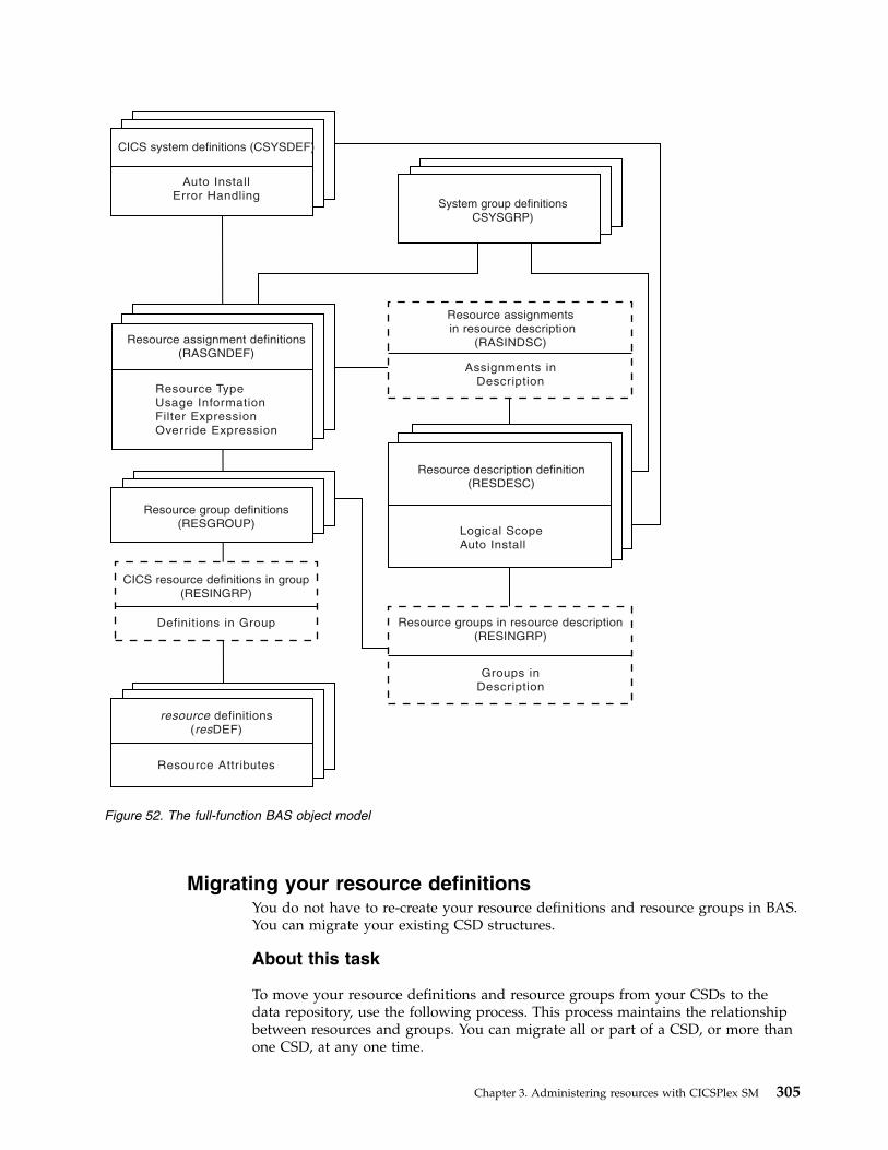
Migrating your resource definitionsYou do not have to re-create your resource definitions and resource groups in BAS.You can migrate your existing CSD structures.
About this task
To move your resource definitions and resource groups from your CSDs to thedata repository, use the following process. This process maintains the relationshipbetween resources and groups. You can migrate all or part of a CSD, or more thanone CSD, at any one time.
Auto InstallError Handling
Resource group definitions(RESGROUP)
CICS resource definitions in group(RESINGRP)
Definitions in Group
Resource description definition(RESDESC)
Logical ScopeAuto Install
resource
res
definitions( DEF)
Resource Attributes
CICS system definitions (CSYSDEF)
Resource assignmentsin resource description
(RASINDSC)
Resource groups in resource description(RESINGRP)
Assignments inDescription
Groups inDescription
Resource assignment definitions(RASGNDEF)
Resource TypeUsage InformationFilter ExpressionOverride Expression
System group definitionsCSYSGRP)
Figure 52. The full-function BAS object model
Chapter 3. Administering resources with CICSPlex SM 305

Procedure1. Use the EXTRACT command of the DFHCSDUP utility routine to read the CSD
records.2. Use the CICSPlex SM extract routine EYU9BCSD to create batched
repository-update facility commands.3. Input these commands to The batched repository-update facility in
Administering to create resource definitions and resource groups, and theobjects that link them.
Defining resourcesYou can use BAS to define and maintain resource definitions across a CICSplex. Bycreating resource definition objects in the data repository, you can use these objectsas templates for creating large numbers of resource definitions.
The definition of resources for CICSPlex SM is similar to CICS RDO. To define aresource, you create a resource definition object. You describe the attributes of theresource in the definition but you do not have to define every occurrence of everyresource; you can use a small number of resource definitions as templates for thecreation of large numbers of resources. The resource definitions are stored in thedata repository for the CICSplex.
The differences between CICSPlex SM resource definition objects and CICSresource definitions are:v The same resource definition can be used by any CICS region in the CICSplex,
across all supported platforms.v You can define to CICSPlex SM all the attributes of each resource, including both
local and remote values. CICSPlex SM determines the correct subset of attributesto use when the resource definition is assigned to a CICS region.
v You do not have to define every instance of your resources from scratch. Youcan create a resource definition as a “template” for many resources with similar,even identical, attribute values. You can specify temporary or permanentvariations, called overrides, for CICSPlex SM to create resources with differentsets of values.
v You can create multiple versions of the same named resource definition. Eachversion is effectively a different resource definition, and can be used by differentCICS systems or for different system requirements. For example, you might havedifferent resource requirements for development and test systems. See“Validating resources.”
You can create resource definition objects in three ways:v Use the administration views in CICS Explorer or the BAS administration and
definition views in the Web User Interface.v Use the batched repository-update facility; see The batched repository-update
facility in Administering.v Use the CICSPlex SM API; see Developing CICSPlex SM applications.
Validating resourcesBAS performs many of the same resource definitions checks as RDO does.
As individual resources are defined and installed, BAS checks:v Individual attributes of a resourcev Interdependent resources attributes
306 CICS TS for z/OS: CICSPlex SM Concepts and Planning

v Release-specific resource attributes
In addition, BAS checks that each set of resources is consistent. Every time youmake a change to a resource set, BAS checks that the resource being added orupdated is not in conflict with a resource already in the CICS system. For example,you would get an inconsistent set error if you tried to assign different versions ofthe same resource to the same CICS system, or assign a resource as both local andremote.
BAS also provides a MAP function that allows you to check that your resourceassociations are what you want. You use this facility to display the structure ofyour resource associations, starting at any point in hierarchy.
Defining resource groupsA resource group is a set of related resource definitions that you want to manage asa unit. Resources groups are defined using the Resource group view (RESGROUPobject). The resource definitions in a group may be of the same type or of differenttypes, but usually have something in common. They might be logically related bytheir use in a given application or communications network, or geographicallyrelated by their use at a given site.
There is no real limit to the number or combination of resource definitions that canmake up a group. However, only one version of any given resource can beincluded in a resource group at one time. You have to maintain each version of aresource definition in a different resource group.
Using migration form BASWith migration form BAS, your resource groups are associated directly withresource descriptions.
A resource description specifies whether or not you are using logical scoping, andthe CICS systems for the resource groups associated with the resource description.See Figure 51 on page 304.
When you have migrated or defined your resources and resource groups, you needto create resource descriptions to define your applications. Resource descriptionsare defined using the RESDESC object. A resource description is directly related toone or more resource groups that are to be managed as an entity. In the migrationform BAS model, this relationship can be considered to represent a logical scope,but the resource description is really analogous to a RDO group list, in that all theresources are tied to a given CICS system or CICS system group.
Using full-function form BASWith full-function form BAS, resource groups are not associated directly withresource descriptions.
An additional object, the resource assignment (RASGNDEF), defines thecharacteristics and usage of a selected resource type from a resource group. Theresource assignment is associated with a resource description, which can then beused to represent a business application. See Figure 52 on page 305.
These objects are used to define your resources in terms of their businessapplication.
Chapter 3. Administering resources with CICSPlex SM 307

Using resource assignmentsPower and flexibility in the management of resources is offered by the resourceassignment (RASGNDEF) object.
Note: If you are using the migration form of BAS, you do not use resourceassignments.
Each resource assignment relates to one resource type within a resource group, andit must be associated with a resource description, if it is to be used in logicalscoping or automatically installed. Each resource group can be in more than oneresource assignment.
You can further refine the selection of resources within the type specified by theresource assignment by using a filter expression, and you can change the resourceattributes using an override expression. You can combine in the expression anunlimited number of attribute values, using the logical operators AND, OR, andNOT. When the resource description is specified as the scope, CICSPlex SMprocesses only those resources that meet the specified selection criteria. This givesyou a great deal of control over the management of your resources.
Each resource assignment must be added to a resource description, if it is to beinstalled and used in logical scoping. Creating resource assignments and addingthem to a resource description enables you to manage sets of resources with alogical scope that can span many CICS systems. In this case, the resourcedescription becomes, in effect, a user-defined, logical set of resources, such as anapplication. You might have several different resource descriptions associated witha given CICS system, each one representing a different set of resources.
For example, with a resource assignment, you can:v Select specific resources from a resource group.v Identify the CICS systems where local and remote instances of a resource should
be assigned.v Temporarily override the values of specific resource attributes.
The resources selected by a resource assignment cannot be managedindependently. The resources must be members of a resource group and the resourceassignment must be associated with at least one resource description.
Using resource descriptionsWith full-function BAS, a resource description represents an application, that is, aset of logically-related resources that can span more that one CICS system. Theresource description thus identifies the logical scope of the application.
Each resource group to be used as part of the application must be added to theresource description. You can associate whole resource groups with a resourcedescription to create a larger set of resources (much like a CSD group list). Thisallows you to manage the resources more efficiently. The set of resources identifiedin a resource description can be:v Identified as a logical scope (such as an application) for use in subsequent
CICSPlex SM requestsv Installed either automatically, when the CICS system identifies itself to CICSPlex
SM as a MAS, or dynamically, while the CICS system is up and running.
308 CICS TS for z/OS: CICSPlex SM Concepts and Planning

The BAS objects that are used for creating and managing these resourceassociations shown in Figure 51 on page 304 and their functions are summarized inTable 17 on page 302.
Installing applications and resourcesOptionally, as an alternative to installing resources from the CSD, you can use BASto install your resources, from the data repository.
BAS allows you to install all the resources associated with an application, byinstalling the resource description, or one resource group. BAS applies anyresource assignments you have associated with the application resource descriptionor resource group, and selects the actual resources to be installed on the basis ofthose criteria. Alternatively, you can install an individual resource into one or moreCICS systems, either locally or remotely, as appropriate.
BAS can install resources either automatically at system initialization time ordynamically into an active CICS system. Before installing a resource, CICSPlex SMperforms checks to determine whether the resource already exists in the CICSsystem. The normal situation is that if the resource exists, the new resource isconsidered a duplicate and is not installed. However, when you dynamically installresources, BAS offers the option of bypassing the duplicate resource checking andforcing the unconditional installation of resources.
Automatic installation When a CICS system initializes and identifies itself to a CMAS, BASreviews the resources associated with that system and decides the set ofresources to be installed.
Dynamic installation You can install resources dynamically into an active CICS system byclicking the install button either from the appropriate resource definitionview, or from one of the following views:v Resource group definitions view.v Resource description definitions view.v System link definitions view.
Security considerationsBecause of the importance of resource definitions to your CICSPlex SMenvironment, you need to consider carefully the implications of allowing usersaccess to certain types of resource or to certain functions.
You can allow a user to have access to all resource definition views and theirrelated administration views, or you can restrict access to the definition views for aparticular resource type. You can also define the type of access a user has, forexample, one user might have read-only access to ISC/MRO connectiondefinitions views (CONNDEF object) and Session definitions views (SESSDEFobject), but update access (which permits creation and administration of resources)to all other resource types. You need to make sure that the BAS views areadequately protected, so that unauthorized users cannot create and administerresources.
You should also take care if you are running CICS TS, and are using the EXECCICS CREATE command to build new resources. Any definition created with theCICSplex as the context is automatically distributed to all CMASs in the CICSplex.Therefore, giving a user authority to create BAS objects is potentially equivalent to
Chapter 3. Administering resources with CICSPlex SM 309

giving authority to install resources on any CICS system in the CICSplex. Whenthe CICS system starts, there is no check on who installed the resource in thesystem.
For details on setting up security for CICSPlex SM at your enterprise, see BASsecurity considerations.
Planning for BASBAS allows you to create CICSPlex SM objects that define your resources and togroup them in such a way that you have close control over the running of yourapplications.
You do not have to transfer all your CSD resources to CICSPlex SM at the sametime, neither do you have to decide at the outset which approach you will use. Youcan extract the resource definition records from one or more CSDs, or only a subsetof records from one CSD. You can move directly to using full-function BAS, or youcan use migration form BAS, and gradually move towards full-function BAS. Youcan use RDO, migration form BAS, and full-function BAS in the same CICSplex.
This section poses some of the questions you might like to consider when you startplanning to implement BAS in your enterprise:v If you are going to use the extract facilities:
– In what order do you want to extract your CSDs?– Do you want all the records from a CSD or a subset?– Are you going to extract more than one CSD at a time?
v Are you going to use the migration form approach?v Are you going to implement full-function BAS? You then need to think about
how your business applications use resources and the assignments you need tocreate.
v Which resources are to be installed automatically and which are to be installeddynamically?
v Which definitions are required before PLT processing? Definitions requiredbefore PLT phase 2 processing must be in the CSD.
v Where are the resources to be installed?v Do you need to define manually any resources that are not defined in the CSD?v What security measures do you need to implement? (See “Security
considerations” on page 309).
The CICS Interdependency Analyzer can assist you in the planning andunderstanding of your application resource flow; it shows you:v Transaction resource dependencies; that is, the sets of resources used by
individual CICS transactions, and on which the transactions depend in order torun successfully
v Transaction affinities; that is, those groups of transactions that have affinitieswith each other, meaning that the whole group must be installed in the sameregion, or in a particular region
For more information about CICS Interdependency Analyzer, see CICSInterdependency Analyzer for z/OS.
Implementing BASThis section describes a route you could take to implement BAS on your CICSplex.
310 CICS TS for z/OS: CICSPlex SM Concepts and Planning

Creating migration for BASThe first stage in the process of moving to using BAS is to migrate your resourcesfrom CICS to CICSPlex SM:v Move your resource definitions, resource groups, and the relationships between
them, from the CSD to the CICSPlex SM data repository. This process, which isdescribed in “Migrating your resource definitions” on page 305, gives you anintermediary resource hierarchy that is very like CEDA, in that each resourcedefinition is in a resource group.
v Create definitions and groups for any resources that are not held on the CSD.v Create applications by associating each resource group with a resource
description.
There are no resource assignments and, although you can now run your CICSPlexSM system perfectly satisfactorily, you will not be taking advantage of the specialfunctionality offered by BAS.
Once you have extracted your CEDA definitions, you can proceed to migrate yourresource definitions to full BAS function, as described in “Migrating to the use ofresource assignments.”
Migrating to the use of resource assignmentsYou don't have to migrate all your resources to resource assignments at the sametime.
You can identify certain resources in which you are interested, remove them fromdirect association with resource definitions, and create resource assignments, usingthe Resource assignment definitions view (RASGNDEF object) for them. Whenyou are happy with the resource assignments, you can move on to defininganother set of resource definitions.
As you move towards processing your resource definitions more full-functionally,you should remove resource groups from direct association with a resourcedescription and identify them instead in one or more resource assignments.
Note: You can use the same resource description to manage both whole resourcegroups and selected resources identified in resource assignments. As you begin totake advantage of the resource assignment capabilities, you may have to updatesome of the underlying resource definitions. For example, a resource definition thatwas previously associated as is with a CICS system might require additionalattributes before it can be assigned as both a local and remote resource in differentCICS systems.
A recommended approachWhen you decide to implement BAS functions in your enterprise, you shouldbegin by defining the appropriate objects.
This section summarizes the preceding sections. You should:v Extract resource definitions and resource groups from the CSD, as described in
“Migrating your resource definitions” on page 305. Alternatively:– Use the appropriate resource definition views to create resource definitions.– Use the Resource group definitions view to create resource groups
(RESGROUP objects).v Use the Resource assignment definitions view to create resource assignments
(RASGNDEF object) .
Chapter 3. Administering resources with CICSPlex SM 311

v Use the Resource description definitions view to a create resource descriptionto associate the definitions and assignments just created (RESDESC object).
Then, to create associations between these objects:v Use the appropriate resource definition view to add resource definitions to a
resource group (RESINGRP object).v Use the Resource group definitions (RESGROUP) view to add the resource
group to a resource description (RESINDESC object).v Use the Resource assignment definitions view (RASGNDEF object) to associate
the resource assignment with a resource description (RASINDSC object).v Use the Resource assignment definitions view (RASGNDEF object) to associate
the resource assignment with a CICS system or CICS system groups.
You can use the Map action button to display a visual map of the BAS definitionsin your data repository. If you want to see a list of the objects and associations youhave already defined, use the Resource definitions in resource groups view(RESINGRP object).
Where next?Once you have identified your BAS requirements, you need to set up yourresources and their associations.
This is described in Creating resources with BAS.
312 CICS TS for z/OS: CICSPlex SM Concepts and Planning

Chapter 4. Monitoring CICSPlex SM
There are several methods you can use to monitor CICSPlex SM.
Monitoring using real-time analysis (RTA)Real-time analysis is the component of CICSPlex SM that you use to define andmanage notification of exception conditions at your enterprise.
When you have identified your RTA requirements, define them to CICSPlex SM asdescribed in Working with real-time analysis administration views.
What is real-time analysis?CICSPlex SM real-time analysis (RTA) function provides automatic, external,notification of conditions in which you have expressed an interest.
Real-time analysis is not concerned solely with commonly recognized errorconditions: you can ask to be notified about any aspect of a resource's status.
The RTA functions are:v System Availability Monitoring (SAM): see “System Availability Monitoring
(SAM)” on page 315v RTA resource monitoring, which includes:
– MAS resource monitoring (MRM): see “MAS resource monitoring (MRM)” onpage 316
– Analysis point monitoring (APM): see “Analysis point monitoring (APM)” onpage 317
For example, if you tell CICSPlex SM that all files used by CICS systems AORPAY1must be in ENABLED status, CICSPlex SM sends out warning messages when thestatus of any of those files is other than ENABLED. However, CICSPlex SM isn'trestricted to telling you about a problem only after it has occurred. CICSPlex SMreal strength lies in its ability to detect potential problems with CICS resources.Indeed, CICSPlex SM is unrivaled in its ability to detect and warn of the slightestchange in the status of a CICS resource. For example, CICSPlex SM can tell youthat resource contention is growing, or that the dynamic storage area (DSA) freespace is falling, or that the number of users of a particular transaction is high:these can all be indicators of future problems that you could avoid by takingpreventive action.
The notification can take the form of a console message, or of a generic alert toNetView, or both. The CICSPlex SM application programming interface (API)makes it possible for automation products actively to gather status informationfrom CICSPlex SM, rather than waiting for CICSPlex SM to send out MVSmessages and SNA generic alerts.
Why automate?The CICSPlex SM operator can monitor RTA messages and take appropriate action.
For example, the CICSPlex SM operator can change the status of a file fromDISABLED to ENABLED using the CICSPlex SM Local files view set (LOCFILE
© Copyright IBM Corp. 1989, 2018 313
object). However, this approach is becoming less satisfactory as CICS availabilityand performance requirements grow. Most enterprises are using more and moreCICS systems, often via cloning, to process a growing workload. This factor alonehas made the CICSPlex SM operator's task more difficult and error prone. At thesame time, however, service-level agreements are setting performance andavailability targets that are more demanding than ever before. Consequently, theideal environment is one in which the CICSPlex SM operator is presented withproblems only in the most exceptional circumstances. Such an environment is nowpossible, because most actual and potential problems detected by CICSPlex SM canbe corrected or prevented by intelligent use of automation products, such as:v NetViewv Automated Operations Control/MVS (AOC/MVS)v Automated Operations Control/MVS CICS Automation (AOC/MVS CICS
Automation)v CICSPlex SM itself. (Not only does CICSPlex SM provide detailed and timely
information about CICS resource status to other automation products, it is alsocapable of correcting many of the problems it detects.)
The RTA external notificationsAn RTA external notification is generated when the status of a CICS resource is notas expected. The notification can take the form of either an external message or anSNA generic alert, or both.
External messages:
External messages are operator messages that are written to the MVS console bydefault. External messages can also be viewed from the CICSPlex SM RTAoutstanding events view (EVENT object) while a condition is active.
When a condition has been resolved, it disappears from the RTA outstandingevents view (EVENT object). (However, external messages written to the RTAoutstanding events view (EVENT object) view are also written to the CICSPlex SMEYULOG to provide a record of the contents of the RTA outstanding events view(EVENT object).) In the RTA outstanding events view (EVENT object), externalmessages are sorted in order of urgency, with the message about the most urgentcondition at the top of the list. The urgency of a condition is user-defined.
External messages are issued in pairs: one message is issued at the start of acondition, and another is issued when the condition ends. The messages all havethe prefix “EYUPN”. External messages can be intercepted by automationproducts, such as NetView, AOC/MVS, and AOC/MVS CICS Automation.
SNA generic alerts:
CICSPlex SM can construct SNA generic alerts and transmit them, via the NetViewprogram-to-program interface (PPI), to NetView for processing.
NetView can trap SNA generic alerts in its automation table, which can either takeaction itself to resolve the problem, or start some automation code from acommand list (CLIST) or command processor.
Advantages of RTAThere are a number of advantages of using RTA. These are as follows:v Actions can be taken within CICS, removing the requirement to use external
automation products.
314 CICS TS for z/OS: CICSPlex SM Concepts and Planning

v Potential problems are detected and corrected before they become critical.v Performance to the end-user is improved by the early detection of bottlenecks
that could affect response time.v The volume of information presented to operators is reduced by filtering out
unnecessary messages.
System Availability Monitoring (SAM)CICSPlex SM has a system availability monitoring (SAM) function that monitorsCICS systems during their planned hours of availability.
If any of a set of predefined conditions occurs while a CICS system is beingmonitored, CICSPlex SM sends out external notifications at the start of thecondition and also when it is resolved. The conditions are:
SAMMAXCICS has reached maximum tasks.
SAMOPSThe CICS system is not available.
SAMNRMA CMAS has lost contact with an active MAS that it is managing.
The SAMNRM event is raised after the MAS fails to respond to a queryfrom the CMAS for a period of 60 seconds. Unlike other SAM conditions,this event can be detected only when the CMAS interacts with the MAS.The condition is not detected if no CMAS to MAS interaction occurs.
SAMSDMA CICS system dump is in progress.
SAMSOSA CICS dynamic storage area (DSA) is short on storage.
SAMSTLOne or more tasks in a CICS system are stalled because of contention forresources such as DBCTL, DL/I, transient data, files, journals, andtemporary storage .
SAMTDMA CICS transaction dump is in progress.
For example, if CICS system AORPAY2 must be active from 0900 hours to 1200hours and CICSPlex SM finds it inactive at 0930 hours, CICSPlex SM issuesexternal messages by default. A typical response, from the CICSPlex SM operatoror from an automation product, would be to try to restart the CICS system, orperhaps to start another.
Customizing the SAM external notificationsWhen any of the SAM conditions occurs, CICSPlex SM issues an external messageby default.
Each of the SAM conditions has a default severity and priority value thatdetermines the position of the external message, relative to other externalmessages, in the EVENT view. For example, the SAMTDM condition has a severityof HW (High Warning) and a priority of 128, whereas the SAMSOS condition has aseverity of HS (High Severe) and a priority of 255 (the highest priority), soSAMSOS precedes SAMTDM in the RTA outstanding events view (EVENT object).
Chapter 4. Monitoring CICSPlex SM 315

You can customize the default SAM notifications for any CICS system by creating aCICSPlex SM action definition. Using an action definition, you can change:v The type of notification that is issued for a SAM condition. For example, you
could specify that, for a particular CICS system, the SAMSOS condition willcause an SNA generic alert to be sent to NetView (so that NetView can takecorrective action), and that no external message is to appear in the RTAoutstanding events view (EVENT object).
v The severity value and the priority value of a SAM condition. For example, youcould specify that the SAMTDM condition must have a severity of LW (LowWarning) in a particular CICS system, and that the SAMSOS condition musthave a priority of 128.
You can also use the action definition to request that CICS TS systems affected by acondition are to be cancelled and restarted using the MVS automatic restartmanager (ARM). This might be a suitable automation action for the SAMOPScondition, for example.
Automation and SAMAn automation product, such as AOC/MVS or NetView, can intercept SAMnotifications and take corrective action, such as starting up or shutting down aCICS system, disabling a transaction, or requesting a dump.
For example, if a CICS system becomes unavailable, one of the automationproducts could attempt to restart the system, or perhaps start another.
However, most of the SAM notifications relate to actual problems that are alreadyhaving an effect on users, so your scope for preventive action is small.Consequently, the best automation option for most SAM conditions is usually torequest a dump, which can provide more information about a problem and itscauses.
MAS resource monitoring (MRM)Using CICSPlex SM MAS resource monitoring (MRM) function, you can monitorthe status of any specific or generic CICS resource, and be informed when its statusdeviates from a specified norm.
(SAM, by contrast, is the monitoring and evaluation of a “default” resource, theCICS system itself. Although you can tailor the type of notification you receivefrom SAM, the condition that triggers the notification is defined by CICSPlex SM.)Using MRM, you can select both the resource status you are interested in and thetype of external notification it generates. Here are some examples of the ways inwhich MRM can be used:v You can use MRM to inform you of changes in the absolute status of a resource.
For example, if the status of an LU6.2 connection is ever RELEASED at a timewhen you have specified it must be ACQUIRED, external notifications can beissued so that the CICSPlex SM operator or an automation product can attemptto reacquire the connection. MRM can warn you of changes in the absolutestatus of many resources. For example, you can ask to be informed when ajournal is CLOSED, when a transient data queue is DISABLED, when a FEPInode or a terminal is OUTSERVICE, when a transaction is DISABLED, and soon.
v In addition to monitoring absolute status values of CICS resources, CICSPlex SMcan provide information about subtle changes in a resource status, such asdegradations in the response time of a transaction, or increases in the number of
316 CICS TS for z/OS: CICSPlex SM Concepts and Planning

users of a program, or changes in the number of Db2 threads in a CICS system.These are all examples of trends in resource behavior that might be indicators ofincipient problems.
v Using MRM, you can specify complex conditions. For example, you can ask foran external notification to be issued when the number of users of a particulartransaction reaches a specified level and the dynamic storage area (DSA) free sizeis falling. Only when both conditions are true is the notification issued.Conditions can be of any complexity.
v MRM even supports the monitoring of non-CICS resources, such as Db2, and ofother members of the CICS family, such as CICS/400, by invoking user-writtenprograms called status probes.
As its name suggests, MAS resource monitoring operates at the CICS system level.That is, if a resource's status changes in two regions, two sets of externalnotifications are issued, one for each region.
Automation and MRMMRM offers great scope for automation of CICS resource management, because itcan alert you to both actual and potential problems.
In alerting you to actual problems, MRM provides you with an opportunity to takeremedial action; in alerting you to potential problems, MRM provides you with anopportunity to take preventive action. Furthermore, an automated response ispossible to all MRM-detected problems.
When changes in the absolute status of a resource occur (for example, when a filethat should be ENABLED becomes DISABLED, or when a connection that shouldbe INSERVICE goes OUTSERVICE), remedial action is usually required. CICSPlexSM itself can correct the status of such resources automatically, as can any of theautomation products, such as NetView or AOC/MVS CICS Automation.
When more subtle changes in a resource's status occur, an automation productsuch as NetView can tailor its response to the severity of the problem. Forexample, CICSPlex SM could monitor the DSA free size in a CICS system everyfive seconds. If CICSPlex SM finds the DSA free size to be:v Between 86KB and 100KB 4 times in succession, it issues an SNA generic alert to
NetView with a severity of LW (low warning)v Between 71KB and 85KB three times in succession, it issues an SNA generic alert
to NetView with a severity of LS (low severe)v 70KB or less twice in succession, it issues an SNA generic alert with a severity of
VLS (very low severe).
In response to any of these alerts, the NetView automation table could issue anMVS modify command to the affected region to increase the DSA size dynamically,thereby preventing a short-on-storage condition (the SAMSOS condition, in fact)from occurring. The amount by which the DSA is increased in each case couldvary according to the severity attached to the SNA generic alert by CICSPlex SM.
Analysis point monitoring (APM)CICSPlex SM has an analysis point monitoring (APM) function which is the sameas its MRM function, except that when resources are monitored in multiple CICSsystems (a CICS system group or an entire CICSplex), the occurrence of the sameproblem in any number of those CICS systems can result in one externalnotification rather than several.
Chapter 4. Monitoring CICSPlex SM 317

APM is especially useful in environments that use cloned AORs, where regions areidentical and one notification is sufficient to alert you to a general problem. APMdoes not support the use of status probes for monitoring non-CICS resources. In allother respects, however, APM offers the same opportunities as MRM for earlydetection of potential problems, and for an automated response in such situations.
Managing RTARTA is set up and managed using the WUI view sets and resource objects.
This is described in Table 18.
Table 18. Real-time analysis objects
WUI view set Object name Description
Installed analysis definitionsassociated with an analysispoint specification
APACTV This object shows information about RTA definitionsassociated with an RTA point specification.
Action definitions ACTION An action definition designates the type of externalnotification that is to occur when the condition orconditions identified in an RTA definition are true.
RTA analysis pointspecifications
APSPEC This object shows information about RTA pointspecifications. An RTA analysis point specificationidentifies one or more CMASs that are to be responsiblefor analyzing CICS systems within the CICSplexidentified as the context.
RTA specifications inprimary CMASs
CMDMPAPS This object shows the association between RTAspecifications and a primary CMAS.
RTA specifications insecondary CMASs
CMDMSAPS This object shows the association between RTAspecifications and secondary CMASs.
Evaluation definitions EVALDEF This object shows information about evaluationdefinitions. An evaluation definition identifies theresources in one or more CICS systems that are to besampled and evaluated. When the result of theevaluation is true, an associated RTA definition is usedto determine if a notifiable condition has occurred.
Real Time Analysis (RTA)outstanding events
EVENT This object shows information about outstandingchanges in the status of a CICSplex or one of its CICSsystems.
Specifications to systemgroup links
LNKSRSCG This object shows CICS system groups associated withanalysis specifications.
RTA specifications to CICSsystem links
LNKSRSCS This object shows CICS systems associated with analysisspecifications.
Real Time Analysis (RTA)installed analysis and statusdefinitions
RTAACTV This object shows information about RTA and statusdefinitions installed in CICS systems known to theCICSplex identified as the current context.
RTA definitions RTADEF An RTA definition identifies the evaluations to beperformed on a periodic basis and the actions to betaken should a notifiable condition occur.
RTA groups RTAGROUP An RTA group is used to associate one or more relatedRTA definitions, status definitions, or both.
RTA group in analysis pointspecifications
RTAINAPS This object displays the names of RTA groups associatedwith RTA point specifications.
RTA definitions in RTAgroups
RTAINGRP This object displays the names of RTA groups and theRTA and status definitions associated with them.
318 CICS TS for z/OS: CICSPlex SM Concepts and Planning

Table 18. Real-time analysis objects (continued)
WUI view set Object name Description
RTA groups in RTAspecifications
RTAINSPC This object shows the names of RTA specifications andthe RTA groups associated with them.
RTA specifications RTASPEC An RTA specification identifies the default controlattributes that are used for system availabilitymonitoring and provides an anchor for all RTAdefinitions and status definitions associated with a CICSsystem.
Status definitions in RTAgroups
STAINGRP This object shows status definitions in RTA groups.
Status probe definitions STATDEF A status probe definition identifies a user-program thatis to be called by CICSPlex SM at specific intervals.
The RTA object model is shown in Figure 53 on page 320. This figure shows thetitles of the WUI views with the names of the resources in parentheses.
Chapter 4. Monitoring CICSPlex SM 319

RTA groups (RTAGROUP)
RTA definitions (RTADEF)
System group definitions(CSYSGRP)
CICS system definitions (CSYSDEF)
RTA specifications (RTASPEC)
RTA groups in RTA specifications(RTAINSPC)
RTA definitions in RTA groups(RTAINGRP)
Time period definitions(PERIODEF)
Groups in Specification
Definitions in Group
Active Period
RTA Active
SAM ActionSAM Severity
Sample Interval
Event
Sample Interval
Program Name
Evaluation Definitions
Console Message
Resource Table
Call Interval
Entry and Exit Intervals
NetView Alert
Resource Names
Exit and Entry Intervals
Action
ARM Restart
Evaluation String
Action
Perform Modification
Modification String
Action definitions (ACTNDEF)
Status probe definitions(STATDEF)
Evaluation definitions (EVALDEF)
Figure 53. The real-time analysis object model
320 CICS TS for z/OS: CICSPlex SM Concepts and Planning

Planning for RTAWhen you are planning to implement RTA, you might consider the followingpoints:v You will probably want to use SAM, because not only is it very easy to
implement (see “Implementing system availability monitoring (SAM)”) but youwill need to be aware when any of your CICS systems are not active when theyshould be. You need to:– Decide whether you want to customize any of the default conditions– Identify the primary CMAS for each CICS system
v To use MRM and APM, you need to identify:– The resources you are interested in– The point at which their status becomes of interest to you– How you want to be notified of an interesting status– The interval at which you require resource evaluations– The interval at which you require data analysis– The primary CMAS
Note: For APM only, you may also specify one or more secondary CMASs.
Implementing RTAReal-time analysis should be implemented gradually and in response to anestablished need for the resultant information, especially if you are not planning toautomate your responses to exception conditions.
You are recommended to begin by implementing SAM, and to implement MRMafter having analyzed records, such as problem logs, that give you some indicationof where MRM would be useful.
Implementing system availability monitoring (SAM)You are recommended to implement SAM as follows:1. Use the Time period definitions view to create time-period definitions
(PERIODEF objects) for the expected availability times of each CICS system tobe managed by CICSPlex SM. For example, if seven of your CICS systemsshould be active from 0800 hours through 1900 hours, create one time-perioddefinition for that part of the day.
2. When you define each CICS system to CICSPlex SM, supply the name of thetime-period definition that defines the system's hours of availability.
These two actions are sufficient to activate SAM and to cause the default externalnotifications to be generated when a noteworthy condition occurs. As you can see,you can implement SAM as soon as CICSPlex SM is installed in your enterprise,and with very little additional effort. You are recommended to continue using SAMwith the default notifications, at least until you have had an opportunity to see thedefault notifications of all SAM conditions. If you decide to customize any of thenotifications, start by creating an action definition for one of the SAM conditionsand apply it to a single CICS system to test the effects. When you are happy withthe change, apply it to other SAM conditions and other CICS systems, asappropriate.
The overheads associated with SAM are not high, so you can activate it throughoutthe enterprise CICSplexes without affecting the general performance of CICSPlexSM or the CICS systems it manages.
Chapter 4. Monitoring CICSPlex SM 321

Implementing MAS resource monitoring (MRM)You should start by implementing MRM on a system-by-system basis. Select asingle resource type, such as connections or files, in a single CICS system, andcreate these CICSPlex SM objects:v An evaluation definition, to identify the instances of the resource you are
interested in, the frequency with which CICSPlex SM is to evaluate the resourcestatus, how CICSPlex SM is to interpret its findings, and the severity to beassigned to a true condition
v An analysis definition, to identify the frequency with which CICSPlex SM is toanalyze the results and the point at which an external notification should beissued
v An action definition, to identify the type of external notification to be issued
The interval between resource evaluations (as specified in the evaluationdefinition) and the intervals at which data is to be analyzed (as specified in theanalysis definition) should be intelligently matched (and ideally the same). Inparticular, do not analyze the data more frequently than it is evaluated. Also,resource evaluations should be performed as infrequently as possible while stillproviding useful data: the more frequently data is collected, the greater the cost ofits collection.
Begin by installing the analysis definition manually in the active CICS system.When you are satisfied that MAS resource monitoring is working as you expected,consider whether automatic installation of the analysis definition would be useful.If it would, add the analysis definition to an analysis group, and associate theanalysis group with an analysis specification. At this point, decide whether tomonitor additional resources in the same CICS system. To extend MAS resourcemonitoring to other resources, an additional evaluation definition would berequired, an additional analysis definition might be required, but the originalaction definition could probably be reused.
Implementing analysis point monitoring (APM)When you are happy with the MAS resource monitoring results, progress toanalysis point monitoring (APM), which is applied to a logical grouping of CICSsystems. You should consider which CICSplexes are affected by your analysis pointmonitoring requirements, and identify the CMASs involved in management ofthose CICSplexes.
As most of the CICSPlex SM definitions required for MAS resource monitoring canbe reused for analysis point monitoring, the cost of staging the implementation inthis way is not high. For example, a single action definition is likely to be usableby multiple analysis definitions. However, for analysis point monitoring you mustcreate at least one analysis point specification. As in the case of MAS resourcemonitoring, you should start analysis point monitoring with simple definitions,and move gradually to using more complex definitions.
A recommended approachWhen you decide to implement RTA functions in your enterprise, you shouldbegin by defining the appropriate objects.
You should:v Use the RTA definitions view to create an analysis definition (RTADEF object).v Use the Evaluation definitions and Action definitions views to create the
required subcomponents of an analysis definition (EVALDEF and ACTIONobjects).
322 CICS TS for z/OS: CICSPlex SM Concepts and Planning

v Use the RTA groups view to create an analysis group (RTAGROUP object).v Use the RTA specifications view to create an analysis specification (RTASPEC
object).
Then, to create associations between these objects:v Use the RTA definitions view to add the analysis definition to the analysis
group (RTAINGRP object).v Use the RTA groups view to add the analysis group to the analysis specification
(RTAINAPS object).v Use the RTA specifications to CICS system links view (LNKSRSCS object) or
the RTA specifications to CICS system groups links view (LNKSRSCG object)to associate the analysis specification with a CICS system or CICS system group.For more information about the LNKSxSCG parameters, see Special attributeand resource table considerations: LNKSxSCG Records (LNKSMSCG,LNKSRSCG, LNKSWSCG).
You can use the Map action button to display a visual map of the real-timeanalysis definitions in your data repository. If you want to see a list of the objectsand associations you have already defined, use the RTA definitions in RTAgroups view (RTAINGRP object), the RTA groups in RTA specifications view(RTAINSPC object), the RTA specifications to CICS system links view(LNKSRSCS object), and the RTA specifications to CICS system groups links view(LNKSRSCG object).
Collecting statistics using CICSPlex SM monitoringMonitoring is the component of CICSPlex SM that you use to define and managethe collection of performance-related data in your enterprise.
What is monitoring?CICSPlex SM monitoring supports the collection of performance-related data, atuser-defined intervals, for named resource instances within a set of CICS systems.
CICSPlex SM monitoring offers the following advantages:v Summary and detailed information on resources is readily available, enabling
you to provide an improved help-desk service.v System availability and performance are improved by allowing operators to be
more effective in investigating problems and seeking out bottlenecks.
At user-defined intervals, monitoring gathers status information and statistics forselected resources, wherever they exist in the CICSplex, and makes them availableat any point of control. CICSPlex SM gathers information using standard CICSinterfaces (EXEC CICS INQUIRE, EXEC CICS COLLECT STATISTICS) and can beused instead of the CICS Monitoring Facility (CMF). If CMF is running, CICSPlexSM exploits the information provided. Monitoring need not be specified forresources being overseen by real time analysis (see “Implementing RTA” on page321), as these are monitored separately.
The CICSPlex SM monitoring functions are:v Monitoring of resources: see “Monitoring of resources” on page 324v Monitoring interval: see “The monitor interval” on page 324v Sampling interval: see “The sample interval” on page 324
Chapter 4. Monitoring CICSPlex SM 323

Monitoring of resourcesCICSPlex SM has monitor functions that can periodically monitor the performanceof CICS resources.
The data collected by this monitoring activity is either the type of data that iscollected by the CICS command EXEC CICS COLLECT STATISTICS, or is derivedfrom such data, that is, CICSPlex SM calculates rates, totals, averages, andpercentages from the raw statistics data. For local MASs only, CICSPlex SM canalso obtain some detailed monitoring data via the CICS monitoring facility (CMF).
The monitor intervalWhen you monitor the activity of a particular resource, you are usually interestedin its performance over a specific period of time. Therefore, when you define aCICSplex to CICSPlex SM, you specify a monitor interval for the CICSplex.
Use the CICSplex definitions view (CPLEXDEF object) to define a CICSplex. Themonitor interval is a period of time, at the end of which counters holding derivedmonitoring data are reset to zero. For example, if you set the monitor interval to 60minutes, counters are incremented for 60 minutes, then are reset to zero and theaccumulation of monitoring data starts again. This sequence is repeated whilemonitoring is active. The interval is specified in minutes (15 through 1440), anddefaults to 480 minutes (8 hours). Values derived by CICSPlex SM during themonitor interval are prefixed with the letters “MI” in relevant views.
The sample intervalFor each type of resource you monitor (such as files or connections), you specify asample interval. The sample interval governs the frequency with which CICSPlexSM collects performance-related data for selected instances of that resource type.
For example, you can specify a sample interval of 300 seconds for files used in aparticular group of CICS systems. Values derived by CICSPlex SM during thelatest sample interval are prefixed with the letters “CS” in relevant views. Thus,the CS values allow you to identify rapid rates of change, whereas the MI valuesare more useful in identifying longer-term trends.
Managing monitoring functionsThe monitoring functions are set up and managed using the WUI view sets andresource objects.
These are described in Table 19.
Table 19. Monitoring WUI view sets and resource objects
WUI view set Object name Description
Monitor definitions MONDEF A monitor definition qualifies a resource type identifiedin a monitor specification by indicating the occurrencesof the resource that are to be included in or excludedfrom monitoring. A monitor definition also identifieswhich resources are to be reported to the resource statusfacility when it is activated.
Monitor groups MONGROUP A monitor group is used to associate one or morerelated monitor definitions.
324 CICS TS for z/OS: CICSPlex SM Concepts and Planning

Table 19. Monitoring WUI view sets and resource objects (continued)
WUI view set Object name Description
Monitor definitions ingroups
MONINGRP This object displays the names of monitor groups, themonitor definitions associated with them, and the timeperiod during which the monitor definitions are to beactive.
Monitor groups in monitorspecifications
MONINSPC This object displays the names of monitor specificationsand the monitor groups associated with them.
Monitor specifications tosystem group links
LNKSMSCG This object shows CICS system groups associated withmonitor specifications.
Monitor specifications toCICS system links
LNKSMSCS This object shows CICS systems associated with monitorspecifications.
Active monitorspecifications
POLMON This object shows information about monitor definitionsinstalled in CICS systems known to the CICSplexidentified as the current context.
The monitoring object model is shown in Figure 54 on page 326. The titles of theWUI views are followed by the resource names in parentheses.
Chapter 4. Monitoring CICSPlex SM 325

Planning CICSPlex SM monitoringWhen you are planning what to monitor in your enterprise using CICSPlex SM,the following recommendations can help you make best use of the monitoringfunctions that are available.
Always have a use for the monitor data you requestEach resource class with a sample interval greater than zero has a CICStask in each MAS (that is, in each managed CICS system) for which
Monitor group definitions(MONGROUP)
System group definitions(CSYSGRP)
Time period definitions(PERIODEF)
Monitor groups in monitor specifications(MONINSPC)
Groups in Specification
Monitor definitions in groups(MONINGRP)
Definitions in GroupActive Period
CICS system definitions (CSYSDEF)
MON Active
Monitor specifications(MONSPEC)
MON ActiveData RetentionSample IntervalsRODM CMAS
Monitor definitions(MONDEF)
Resource TypeResource NamesInclude or ExcludeRODM Status
Figure 54. The resource monitoring object model
326 CICS TS for z/OS: CICSPlex SM Concepts and Planning

monitoring is required. So, for example, if you activate monitoring oftransactions in every CICS system in a CICSplex, each MAS is supportinga CICS task to monitor transactions at the specified interval. Also, CMASprocessing is required to maintain the monitor-data cache. You can see thatgeneral and unrestricted monitoring would very quickly become anunacceptable overhead. Therefore, do not activate monitoring for any CICSsystem nor for any CICS resource class without being aware of why youwant the data.
Identify resources as specifically as possibleCICSPlex SM monitoring is a specialized function that provides detailedusage and performance data. In general, it will be most useful to you forshort-term trend analysis, in anticipating future problems, or dealing withactual problems. For example:v Resources that are limited in quantity can be candidates for monitoring
if their use levels are high, because the monitor data will help you todecide whether to increase quantities of the resource.
v Resources for which there is contention are also good candidates. Suchdata can help you to assess the impact of contention on throughput.
However, you should give some thought to understanding which resourcesare of greatest interest to you. For example, are you really interested inCICS-supplied resources? Often it is tempting to supply an asterisk (*) asthe resource name, which effectively means any instance of the specifiedresource. If you are not interested in every occurrence, use generic namepatterns; for example, you can ask for monitoring of all transactionsbeginning “PAY” by specifying the resource name “PAY*”. Similarly,resources whose status is being reported to the resource status facilityshould be identified as fully as possible.
Specify as long a sample interval as you canThe shorter the sample interval you specify for a resource class, the greaterthe cost of gathering the monitoring data. For example, if you set thesample interval to one second for every resource, no other CICSPlex SMwork is going to get done at all. Therefore, always specify the longestpossible sample interval at which you can obtain useful data. To determineexactly what this interval should be, you must apply what you alreadyknow about any particular resource instance. In general, the sampleinterval should reflect the probable level of use of the resource: if you findthat successive sampling of a resource is not showing significant changes,you should increase the sample interval. The sample interval should alsohave some relationship to the frequency with which the CICSPlex SM orNetView operator will be looking at the monitor data.
Specify as long a monitor interval as you canThe monitor interval determines the frequency with which countersholding accumulated monitor data are reset to zero. You should set it to avalue that is significant in your enterprise, so that the information you getfrom it is also significant. For example, the interval could be a shiftduration, or some other time during which a particular workload is beingprocessed.
You are recommended not to make the interval too short, not only becauseCICSPlex SM overheads grow as the monitor interval reduces, but alsobecause too short an interval is unlikely to provide you with usefulstatistics.
Chapter 4. Monitoring CICSPlex SM 327
Do not define more monitor specifications than you really needAvoid having too many monitor specifications, not only because of theextra work involved in creating them and associating them with CICSsystems, but also because a CICS system can belong to only one monitorspecification at a time. The more monitor specifications you define, thesmaller the opportunity for establishing a general-purpose monitoringpolicy.
Specify a suitable retention period You don't have to specify a retention period. However, the retention perioddefaults to zero minutes, and so as soon as monitoring stops for any CICSsystem, that system's monitor data is lost. If some unexpected event occurs,the data could be invaluable, so setting the retention period greater thanzero is advisable. Note, however, that if a CICS system stops, monitor datais lost when you restart the system regardless of any retention period youmay have specified. In this case, it's important to look at the monitor databefore you restart the CICS system.
You can set the retention period to any value between 1 and 1440 minutes(24 hours). You can specify a retention period on the monitor specification,in which case that period applies to every CICS system associated with themonitor specification. Alternatively, you can specify a retention period inthe CICSPlex SM CICS system definition.
Decide when to activate monitor definitionsWhen you add a monitor definition to a monitor group, you can specifythe part of the day during which it is to be active. You should makeconsidered use of this feature. For example, you probably will not wantmonitoring active overnight, or during any period when general use is lowand no one is around to view the data, so ensure that monitor definitionsare not in effect at those times. Also, if you're monitoring resources forwhich there is contention, think about when this contention occurs. Is itconstant, or does it occur only between 0900 and 1100 hours? If the latter,limit your monitoring to that period.
Implementing CICSPlex SM monitoringPossibly the best way to implement CICSPlex SM monitoring is to start with nomonitoring at all, and to implement it piecemeal for particular CICS systems andCICS resource instances.
That is:1. Create a monitor specification, and associate it with every CICS system in the
CICSplex. However, ensure that every sample interval remains at its defaultvalue of zero, and that monitor status remains set to “OFF”. This is because theone thing you must have in place before you can gather any monitoring data isa monitor specification. If you follow these instructions, monitoring will beenabled, but not activated.
2. When you decide to monitor a particular resource instance, as used by one ofthe CICS systems in the CICSplex, you must:a. Update the CICS system definition to switch monitoring on, and to specify
a sample interval for the resource. You make this change to an active CICSsystem, using the Topology Runtime MAS display view (MAS object), andit applies for the current execution of the CICS system only.
b. Create a monitor definition to name the resource instance, and install itmanually in the CICS system.
328 CICS TS for z/OS: CICSPlex SM Concepts and Planning

3. Repeat this piecemeal approach to monitoring until it becomes apparent thatyou have some regular requirements. At that point, consider installing themonitor definitions automatically (and for every execution of the CICS system)by adding the monitor definitions to a monitor group, and associating themonitor group with the monitor specification. You can make the sampleinterval and monitor status permanent by setting them either in the monitorspecification—in which case, they apply to all CICS systems associated with themonitor specification and for which an appropriate monitor definition has beenprovided—or in the CICS system definition, in which case they affect no otherCICS system.
You can refine your approach to monitoring gradually, by creating additionalmonitor specifications for the CICSplex, for example, and by using timed monitordefinitions, which are installed automatically for a specified duration. Rememberthat:v Although you can make changes to a monitor specification while it is in use, the
effect of those changes is not felt until the CICS system is next started. Note,however, that you can use the MAS view to change monitoring values for anactive CICS system.
v A CICS system can be associated with only one monitor specification at a time.v You can associate a monitor specification with a CICS system that is already
running, but the effect of that new association is not felt until the CICS system isnext started.
Aim to ensure that any monitor specifications and monitor definitions you providesupport the normal situation, and that CICS system overrides are used for theexceptions.
Activating the resource status facilityTo activate the resource status facility you must do the following:v Update the CICSPlex SM definitions of those CICSplexes whose resources are to
be reported to the resource status facility.v Update or create monitor definitions to set the resource status facility Status flag
to YES and to identify resource instances.v Update or create monitor specifications to set the sample interval for each
resource type.
Instructions for all of these tasks are provided in Administering CICSPlex SM andResource monitoring.
For more information about the resource status facility see the description of theRESSTATUS parameter in CICSPlex SM system parameters.
Using the CICS Monitoring Facility (CMF) with CICSPlex SMSome classes of monitoring data for CICSPlex SM, in particular detailedtask-related data that is displayed in some transaction monitoring views, cannot becollected unless CICS performance class data monitoring is active in the monitoredCICS system.
You can activate performance class data monitoring for an active CICS regionusing the CICSPlex SM operations functions, the CICS monitoring facilitytransaction CEMN, or the SET MONITOR command. Alternatively, you can activateperformance class data monitoring permanently using CICS system initializationparameters.
Chapter 4. Monitoring CICSPlex SM 329

CICS monitoring data is usually written to an SMF data set. However, if youprefer, you can collect monitoring data for use by CICSPlex SM without having itwritten to an SMF data set, by specifying the CICSPlex SM system parameterSUPPRESSCMF. For more information about this parameter, see CICSPlex SM systemparameters.
For more information about the different classes of monitoring data, and aboutcontrolling the CICS monitoring facility, see Introduction to CICS monitoring.
A recommended approachWhen you decide to implement monitoring functions in your enterprise, begin bydefining the appropriate objects.1. Create the following objects:v Use the Monitor definitions view to create a monitor definition (MONDEF
object).v Use the Monitor groups view to create a monitor group (MONGROUP
object).v Use the Monitor specifications view to create a monitor specification
(MONSPEC object).2. Create associations between these objects:v Use the Monitor definitions view to add the monitor definition to the
analysis group (MONINGRP object).v Use the Monitor groups view to add the monitor group to the analysis
specification (MONINSPC object).v Use the Monitor specifications to CICS system links view (LNKSMSCS
object) and the Monitor specifications to CICS system group links view(LNKSMSCG object) to associate the monitor specification with a CICSsystem or CICS system group. For more information about the LNKSxSCGparameters, see Special attribute and resource table considerations:LNKSxSCG Records (LNKSMSCG, LNKSRSCG, LNKSWSCG).
You can use the Map button to display a visual map of the monitor definitions inyour data repository. If you want to see a list of the objects and associations youhave already defined, use the Monitor definitions in groups view (MONINGRPobject), the Monitor groups in monitor specifications view (MONINSPC object),the Monitor specifications to CICS system links view (LNKSMSCS object), andthe Monitor specifications to CICS system group links view (LNKSMSCG object)view.
Where next?Once you have identified your monitoring requirements, you should define themto CICSPlex SM.
This is described in IBM 3174 Functional Description.
330 CICS TS for z/OS: CICSPlex SM Concepts and Planning

Notices
This information was developed for products and services offered in the U.S.A.This material might be available from IBM in other languages. However, you maybe required to own a copy of the product or product version in that language inorder to access it.
IBM may not offer the products, services, or features discussed in this document inother countries. Consult your local IBM representative for information on theproducts and services currently available in your area. Any reference to an IBMproduct, program, or service is not intended to state or imply that only that IBMproduct, program, or service may be used. Any functionally equivalent product,program, or service that does not infringe any IBM intellectual property rights maybe used instead. However, it is the user's responsibility to evaluate and verify theoperation of any non-IBM product, program, or service.
IBM may have patents or pending patent applications covering subject matterdescribed in this document. The furnishing of this document does not grant youany license to these patents. You can send license inquiries, in writing, to:
IBM Director of LicensingIBM CorporationNorth Castle Drive, MD-NC119Armonk, NY 10504-1785United States of America
For license inquiries regarding double-byte (DBCS) information, contact the IBMIntellectual Property Department in your country or send inquiries, in writing, to:
Intellectual Property LicensingLegal and Intellectual Property LawIBM Japan Ltd.19-21, Nihonbashi-Hakozakicho, Chuo-kuTokyo 103-8510, Japan
INTERNATIONAL BUSINESS MACHINES CORPORATION PROVIDES THISPUBLICATION “AS IS” WITHOUT WARRANTY OF ANY KIND, EITHEREXPRESS OR IMPLIED, INCLUDING, BUT NOT LIMITED TO, THE IMPLIEDWARRANTIES OF NON-INFRINGEMENT, MERCHANTABILITY, OR FITNESSFOR A PARTICULAR PURPOSE. Some jurisdictions do not allow disclaimer ofexpress or implied warranties in certain transactions, therefore this statement maynot apply to you.
This information could include technical inaccuracies or typographical errors.Changes are periodically made to the information herein; these changes will beincorporated in new editions of the publication. IBM may make improvementsand/or changes in the product(s) and/or the program(s) described in thispublication at any time without notice.
Any references in this information to non-IBM websites are provided forconvenience only and do not in any manner serve as an endorsement of thosewebsites. The materials at those websites are not part of the materials for this IBMproduct and use of those websites is at your own risk.
© Copyright IBM Corp. 1989, 2018 331

IBM may use or distribute any of the information you supply in any way itbelieves appropriate without incurring any obligation to you.
Licensees of this program who want to have information about it for the purposeof enabling: (i) the exchange of information between independently createdprograms and other programs (including this one) and (ii) the mutual use of theinformation which has been exchanged, should contact
IBM Director of LicensingIBM CorporationNorth Castle Drive, MD-NC119Armonk, NY 10504-1785US
Such information may be available, subject to appropriate terms and conditions,including in some cases, payment of a fee.
The licensed program described in this document and all licensed materialavailable for it are provided by IBM under terms of the IBM Customer Agreement,IBM International Programming License Agreement, or any equivalent agreementbetween us.
Information concerning non-IBM products was obtained from the suppliers ofthose products, their published announcements or other publicly available sources.IBM has not tested those products and cannot confirm the accuracy ofperformance, compatibility or any other claims related to non-IBM products.Questions on the capabilities of non-IBM products should be addressed to thesuppliers of those products.
This information contains examples of data and reports used in daily businessoperations. To illustrate them as completely as possible, the examples include thenames of individuals, companies, brands, and products. All of these names arefictitious and any similarity to actual people or business enterprises is entirelycoincidental.
COPYRIGHT LICENSE:
This information contains sample application programs in source language, whichillustrate programming techniques on various operating platforms. You may copy,modify, and distribute these sample programs in any form without payment toIBM, for the purposes of developing, using, marketing or distributing applicationprograms conforming to the application programming interface for the operatingplatform for which the sample programs are written. These examples have notbeen thoroughly tested under all conditions. IBM, therefore, cannot guarantee orimply reliability, serviceability, or function of these programs. The sampleprograms are provided "AS IS", without warranty of any kind. IBM shall not beliable for any damages arising out of your use of the sample programs.
Programming interface information
CICS supplies some documentation that can be considered to be ProgrammingInterfaces, and some documentation that cannot be considered to be aProgramming Interface.
332 CICS TS for z/OS: CICSPlex SM Concepts and Planning

Programming Interfaces that allow the customer to write programs to obtain theservices of CICS Transaction Server for z/OS, Version 5 Release 5 open beta areincluded in the following sections of the online product documentation:v Developing applicationsv Developing system programsv Securing overviewv Developing for external interfacesv Reference: application developmenthv Reference: system programmingv Reference: connectivity
Information that is NOT intended to be used as a Programming Interface of CICSTransaction Server for z/OS, Version 5 Release 5 open beta , but that might bemisconstrued as Programming Interfaces, is included in the following sections ofthe online product documentation:v Troubleshooting and supportv Reference: diagnostics
If you access the CICS documentation in manuals in PDF format, ProgrammingInterfaces that allow the customer to write programs to obtain the services of CICSTransaction Server for z/OS, Version 5 Release 5 open beta are included in thefollowing manuals:v Application Programming Guide and Application Programming Referencev Business Transaction Servicesv Customization Guidev C++ OO Class Librariesv Debugging Tools Interfaces Referencev Distributed Transaction Programming Guidev External Interfaces Guidev Front End Programming Interface Guidev IMS Database Control Guidev Installation Guidev Security Guidev Supplied Transactionsv CICSPlex SM Managing Workloadsv CICSPlex SM Managing Resource Usagev CICSPlex SM Application Programming Guide and Application Programming
Referencev Java Applications in CICS
If you access the CICS documentation in manuals in PDF format, information thatis NOT intended to be used as a Programming Interface of CICS TransactionServer for z/OS, Version 5 Release 5 open beta , but that might be misconstrued asProgramming Interfaces, is included in the following manuals:v Data Areasv Diagnosis Referencev Problem Determination Guidev CICSPlex SM Problem Determination Guide
Notices 333

Trademarks
IBM, the IBM logo, and ibm.com® are trademarks or registered trademarks ofInternational Business Machines Corp., registered in many jurisdictions worldwide.Other product and service names might be trademarks of IBM or other companies.A current list of IBM trademarks is available on the Web at Copyright andtrademark information at www.ibm.com/legal/copytrade.shtml.
Adobe, the Adobe logo, PostScript, and the PostScript logo are either registeredtrademarks or trademarks of Adobe Systems Incorporated in the United States,and/or other countries.
Intel, Intel logo, Intel Inside, Intel Inside logo, Intel Centrino, Intel Centrino logo,Celeron, Intel Xeon, Intel SpeedStep, Itanium, and Pentium are trademarks orregistered trademarks of Intel Corporation or its subsidiaries in the United Statesand other countries.
Java and all Java-based trademarks and logos are trademarks or registeredtrademarks of Oracle and/or its affiliates.
Linux is a registered trademark of Linus Torvalds in the United States, othercountries, or both.
Microsoft, Windows, Windows NT, and the Windows logo are trademarks ofMicrosoft Corporation in the United States, other countries, or both.
UNIX is a registered trademark of The Open Group in the United States and othercountries.
Terms and conditions for product documentation
Permissions for the use of these publications are granted subject to the followingterms and conditions.
ApplicabilityThese terms and conditions are in addition to any terms of use for the IBMwebsite.
Personal useYou may reproduce these publications for your personal, noncommercialuse provided that all proprietary notices are preserved. You may notdistribute, display or make derivative work of these publications, or anyportion thereof, without the express consent of IBM.
Commercial useYou may reproduce, distribute and display these publications solely withinyour enterprise provided that all proprietary notices are preserved. Youmay not make derivative works of these publications, or reproduce,distribute or display these publications or any portion thereof outside yourenterprise, without the express consent of IBM.
Rights Except as expressly granted in this permission, no other permissions,licenses or rights are granted, either express or implied, to the publicationsor any information, data, software or other intellectual property containedtherein.
334 CICS TS for z/OS: CICSPlex SM Concepts and Planning

IBM reserves the right to withdraw the permissions granted hereinwhenever, in its discretion, the use of the publications is detrimental to itsinterest or, as determined by IBM, the above instructions are not beingproperly followed.
You may not download, export or re-export this information except in fullcompliance with all applicable laws and regulations, including all UnitedStates export laws and regulations.
IBM MAKES NO GUARANTEE ABOUT THE CONTENT OF THESEPUBLICATIONS. THE PUBLICATIONS ARE PROVIDED "AS-IS" ANDWITHOUT WARRANTY OF ANY KIND, EITHER EXPRESSED ORIMPLIED, INCLUDING BUT NOT LIMITED TO IMPLIED WARRANTIESOF MERCHANTABILITY, NON-INFRINGEMENT, AND FITNESS FOR APARTICULAR PURPOSE.
IBM online privacy statement
IBM Software products, including software as a service solutions, (“SoftwareOfferings”) may use cookies or other technologies to collect product usageinformation, to help improve the end user experience, to tailor interactions withthe end user or for other purposes. In many cases no personally identifiableinformation is collected by the Software Offerings. Some of our Software Offeringscan help enable you to collect personally identifiable information. If this SoftwareOffering uses cookies to collect personally identifiable information, specificinformation about this offering’s use of cookies is set forth below:
For the CICSPlex SM Web User Interface (main interface): Depending upon the configurations deployed, this Software Offering mayuse session and persistent cookies that collect each user’s user name andother personally identifiable information for purposes of sessionmanagement, authentication, enhanced user usability, or other usagetracking or functional purposes. These cookies cannot be disabled.
For the CICSPlex SM Web User Interface (data interface):Depending upon the configurations deployed, this Software Offering mayuse session cookies that collect each user's user name and other personallyidentifiable information for purposes of session management,authentication, or other usage tracking or functional purposes. Thesecookies cannot be disabled.
For the CICSPlex SM Web User Interface ("hello world" page):Depending upon the configurations deployed, this Software Offering mayuse session cookies that collect no personally identifiable information.These cookies cannot be disabled.
For CICS Explorer:Depending upon the configurations deployed, this Software Offering mayuse session and persistent preferences that collect each user’s user nameand password, for purposes of session management, authentication, andsingle sign-on configuration. These preferences cannot be disabled,although storing a user's password on disk in encrypted form can only beenabled by the user's explicit action to check a check box during sign-on.
If the configurations deployed for this Software Offering provide you, as customer,the ability to collect personally identifiable information from end users via cookiesand other technologies, you should seek your own legal advice about any lawsapplicable to such data collection, including any requirements for notice andconsent.
Notices 335

For more information about the use of various technologies, including cookies, forthese purposes, see IBM Privacy Policy and IBM Online Privacy Statement, thesection entitled “Cookies, Web Beacons and Other Technologies” and the IBMSoftware Products and Software-as-a-Service Privacy Statement.
336 CICS TS for z/OS: CICSPlex SM Concepts and Planning

Index
Special characters, introduction to 1(CMASD object 45
Aabend compensation
when accessing workloadmanagement directly 293
abend healthABENDCRIT 267
abend loadABENDTHRESH 267
abend probability 267accessibility options 104action buttons 3, 227Action definitions view 318action parameters 226activating workload management 268Active monitor specifications 325adding a CICS system to a CICS system
group 86address space (CMAS)
add CICS system definitions 55administering 45CICS SIT parameters 129CICS system initialization
parameters 57, 62configuration 45create data repository 54defining 45definitions 44links to other CMASs 33maintenance point 37NetView 10performance considerations 30restarting 72START command for a CMAS 68starting
as a batch job 52from the system console 52
use of ESSS 10where to install 30
ADMCONFG menu 46administering the CMAS
configuration 45administering the topology of a
CICSplex 46affinity lifetimes 287affinity, workload
description of 264agent code, MAS 9aggregation
group 15alerts to IBM Tivoli NetView
preparing IBM Tivoli NetView toreceive 51
analysis definition 318analysis group 318
analysis point monitoring (APM)automation and 313description of 318implementing 322
analysis specification 319AOC CICS Automation 314APPC 287application programming interface
(API) 4assigning a CMAS to a CICSplex
definition 87associating a CMAS with a CICSplex 87associating CICS system with CICS
system group 86ATOMDEF object 145, 303Atomservice definitions view 145
ATOMDEF 145ATOMSERVICE definitions view 303attribute filters 226attributes 225auto-import options 99AUTOIMPORTDSN 99AUTOIMPORTMEM 99AUTOIMPORTTDQ 99automatic installation
of a monitor definition 329of an analysis definition 322of resources 309
AUTOREFRESH 101AUTORESETTIME 91auxiliary storage usage 50
Bbacking up the data repository 60bar gauge 224batched repository-update facility 5
description of 5EXTRACT routine 311
batched repository-update job view 45BATCHREP object 45BBACTDEF DD statement
with CMAS startup JCL 52BUNDDEF object 303BUNDLE definitions view 303Business Application Services (BAS)
creating resource definitions 306definition of 2description of 297EXTRACT routine 311functions 297objects 11resource installation 297resource versions 298
CCHS 91CHS1 91CHS2 91
CICS business transaction services(BTS) 255
BTS-set 254CICSplex considerations 254dealing with affinities 254release requirements 264, 272
CICS management client interfaceCICS region setup 125CMCIPORT WUI server initialization
parameter 98DFH$WUTC sample 125DFH$WUUR sample URI map 125security set up 128set up 108, 125, 128storage requirements 123
CICS monitoring data 237, 240CICS Monitoring Facility (CMF) 79, 323,
324, 329CICS SIT parameters 129CICS storage in a CMAS 68CICS system 22
as part of CICS system groupadding to 86
CICS system definition 85CICS system definitions view 47CICS system group 8, 29
adding member to 86creating 85defining 47identifying 47using instead of CICSplexes 27
CICS system initializationparameters 57, 62, 90, 91
CPSMCONN 91CWAKEY 90INITPARM
EYU9VKEC 91EYU9VWAN 91
MNPER 237, 240MNRES 237, 240WRKAREA 90z/OS MAS-related 78
CICS system objects 22CICS system resources view 302CICS-deployed jar file definitions
view 303CICS-deployed JAR file definitions
view 150CICSplex
CMASs associated withadding 87
definition 8definitions 46identifying 25when to have more than one 26
CICSplex definitionsassigning a CMAS to 87creating 84
CICSplex definitions view 45, 46CICSPlex SM 84
initialization parameters 85
© Copyright IBM Corp. 1989, 2018 337

CICSPlex SM address space (CMAS)release level 9
CICSPLEX system parameter 133CICSplex topology
administering 46defining 46
CICSPLEX) view object 45CICSplexes managed by CMAS view 45CMAS 9
create data sets 66customize data sets 66
CMAS ( address space)add CICS system definitions 55CICS SIT parameters 129CICS system initialization
parameters 57, 62restarting 72START command for a CMAS 68
CMAS (address space)create data repository 54starting
as a batch job 52from the system console 52
CMAS (CICSPlex SM address space)controlling CICS storage 68controlling tasks 65
CMAS configuration administrationview 44
CMAS detail view 45CMAS in CICSplex definitions view 45CMAS journaling 69CMAS object 45CMAS to CMAS link definitions
view 45CMAS to CMAS link detail view 45CMAS to CMAS link view 45CMAS to MAS link detail view 45CMAS to MAS link view 45CMAS-specific JCL requirements
BBACTDEF 52CICS EXEC 52DFHRPL 52EYUCMASP 52EYUDREP 52EYULOG 52EYUPARM 52STEPLIB 52
CMASNAME parameter ofEYU9XDUT 55
CMASPLEX object 45CMASs known to local CMAS view 45CMASs managing CICSplex view 45CMASSYSID system parameter 133CMCI
CMCIPORT WUI server initializationparameter 98
DEFAULTWARNCNT 119set up 108setting record count warnings 119storage requirements 123
CMCIPORT 98CMTCMDEF object 45CMTCMLND) object 45CMTCMLNK object 45CMTPMLND object 45CMTPMLNK object 45code page 91
code page (continued)CHS1 91CHS2 91ENU1 91JPN1 91
code page conversion table 92COIRTASKPRI system parameter 134COLG 106color of screens 104COLORINK 105COLORINKBANNER 105COLORINKLINK 105COLORINKVLINK 105COLORPAPER 105COLORPAPERALT 105COLORPAPERERROR 105COLORPAPERHEAVY 105COLORPAPERLIGHT 105COLORPAPERRULE 105COLORPAPERWARN 105COMMNDaa, operator commands
memberfor CMAS 52
communication areasEYURWCOM 289EYURWTRA 291
Components of Favorite screen 209configuration
CMAS 45Configuration administration view 46configuration and topology
establishing CMAS-to-CMASconnections 87
configuring 84configuring CPSM 21confirmation panel 219CONNDEF object 169, 303connecting regions 299copy books 272COVC 107
map objects 243COVE 106COVI 106COVP 106CPLEXDEF 84CPLEXDEF object 45, 46CPLXCMAS object 45CPSM.EYUDREP
in CMAS startup JCL 52CPSM.SEYUADEF
in CMAS startup JCL 52CPSM.SEYUAUTH
in CMAS startup JCL 52CPSM.SEYULOAD
in CMAS startup JCL 52CPSM.SEYUVDEF
in CMAS startup JCL 52CPSM310.SEYUAUTH
in MAS startup JCL 77CPSM310.SEYULOAD
in MAS startup JCL 77CPSMCONN 91creating a transaction affinity 286creating a user-replacement for
EYU9WRAM 289creating CICS system definition
data repository 54
creating CICS system groupdefinition 85
creating resource definitions 306creating typeterms 203creating view sets 230CSYSGRP object 47customizable view and menu help 96,
227writing 227
customizable view and menu help dataset 96
customized map objects 223customizing 207CVDASTYLE 99CWAKEY 90
Ddata repository 4, 12
backing up 60creating 54defining forward recovery log for 61expanding 60for each CMAS 54identified in CMAS startup JCL 52upgrading 54
data-repository initialization job 43DATEFORMAT 100DATESEPARATOR 100DAYLIGHT parameter of
EYU9XDUT 56DB2 connection definition view 303DB2 connection definitions view 148
DB2CDEF 148DB2 entry definitions views view 303DB2 transaction definitions view 152,
303DB2CDEF object 148, 303DB2EDEF object 150, 303DB2TDEF object 152, 303DECIMALSEPARATOR 100default values, setting 212, 214default view 221DEFAULTCICSPLEX 103DEFAULTCICSRGN 103DEFAULTCMASCTXT 101DEFAULTCONNECT 103DEFAULTCONTEXT 101DEFAULTCSYSGRP 103DEFAULTDB2SS 103DEFAULTEJCOBEAN 103DEFAULTEJDJBEAN 103DEFAULTEVENT 103DEFAULTLOCFILE 103DEFAULTLOCTRAN 103DEFAULTMAPBAS 101DEFAULTMAPCOLL 101DEFAULTMAPMON 101DEFAULTMAPRTA 101DEFAULTMAPWLM 102DEFAULTMENU 102DEFAULTNAVIGATE 102DEFAULTPROGRAM 103DEFAULTREMFILE 103DEFAULTREMTRAN 103DEFAULTSCOPE 102DEFAULTTASK 103
338 CICS TS for z/OS: CICSPlex SM Concepts and Planning

DEFAULTWARNCNT 102defining resources
connections 169DB2 entries 150DB2 transactions 152document template 154enqueue model 165FEPI nodes 155FEPI pools 157FEPI property sets 158FEPI targets 160file key segments 164files 162IPIC connections 167journal models 171LIBRARYs 174LSR pools 176map sets 178partition sets 183partners 184pipelines 186process types 187profiles 189programs 190sessions 192TCP/IP service 193temporary storage model 201terminal 196transaction 198transaction class 199transient data queue 194URIMAPs 204web services 206
defining the CMAS configuration 44, 45defining the topology of a CICSplex 46Deployed enterprise java archive
definition view 303derived MONITOR data 324detail view 218
two-column 218detailed views
creating 248DFH$WUTC sample TCP/IP service 125DFH$WUUR sample URI map 125DFHCNV 92DFHHTML 96, 106DFHISTAR
CMASNAME parameter 55customizing CMAS postinstallation
jobs 67customizing MAS postinstallation
jobs 76customizing WUI postinstallation
jobs 95DSINFO 55postinstallation members for a
CMAS 66postinstallation members for a
MAS 75postinstallation members for a
WUI 94DFHRPL (dynamic transaction routing
exit)in CMAS startup JCL 52in MAS startup JCL 77
DFLTUSER system initializationparameter
for z/OS MAS 79distributed program link (DPL) 254, 290,
291release requirements 272
DOCDEF object 153, 303Document template definition view 153document template definitions
view 153, 303DSRTPGM SIT parameter 268, 270DTRPGM SIT parameter 268, 270DTRPROG API 281dynamic installation of resources 309dynamic routing 3
customizing CICSPlex SM processinginstalling user-replacement
programs 289customizing CICSPlex SM processing
CICSPlex SM data areas 289modifying the DTR program 281non-dynamic transactions 282overview of CICSPlex SM
processing 270release requirements 272sample programs 272selecting an target region 283transaction routing actions 283,
285requesting additional support
abend compensationconsiderations 293
EYURWTRA communicationarea 291
invoking CICSPlex SM workloadmanagement 291
overview 290processing considerations 291route error considerations 292sample calling sequence 294transaction affinity
considerations 293
EECLOGMSG system parameter 139editing view sets 230EJCODEF object 303EJDJDEF object 303ENQMDEF object 165ENQMODE object 303Enqueue model definitions view 165enterprise beans
workload routing 256entity types
CICSPlex SM 40entry box 224entry field 224ENU 91ENU1 91Environment Services System Services
(ESSS) 10Evaluation definitions view 318expanding the data repository 60external messages, RTA 314external notifications, RTA 314EXTRACT routine 311
EYU$CNV1 92EYU9DXDUT 43EYU9VKEC 91EYU9VWAN 91EYU9WRAM routing action module 289
copy books 272creating a user-replacement 289
EYU9XDUT 55EYU9XLOP dynamic routing
program 268, 270, 290EYUCHS1 92EYUCHS2 92EYUCMS01
CICS system initializationparameters 57, 62
EYUCMS1A 101EYUCOVE 106EYUCOVI 106EYUDREP data set
creating the data repository 55in CMAS startup JCL 52
EYUENU1 92EYUHISTx 81EYUHISTx DD statement 77EYUJPN1 92EYUJWREP 93EYULOG 106EYULOG DD statement
CMAS startup JCL 52EYUPARM DD statement
in CMAS startup JCL 52in MAS startup JCL 77
EYUPARM parametersdescription of 132summary of 129topology requirements 85
EYUPLX01 101EYURWCOD copy book 272, 289EYURWCOM communication area 272,
289EYURWSVD copy book 272, 289EYURWSVE copy book 272, 289EYURWTRA communication area 291EYUWREP (Web User Interface server
repository) 93, 106EYUWUI 106
Ffavorites 207
creating 212editing 208
favorites editor 207FENODDEF object 155, 303FEPI node list definitions view 155, 303FEPI pool definitions view 157, 303FEPI property definitions view 303FEPI property set definitions view 158FEPI target definition 160FEPI target list definitions view 160, 303FEPOODEF object 157, 303FEPRODEF object 158, 303FETRGDEF object 160, 303file definitions view 162File definitions view 162, 303File key segment definitions view 163file segment definitions view 164
Index 339

File segment definitions view 303FILEDEF object 162, 303filter confirmation screen 220filtering data
in user favorites 209forward recovery log for data
repository 61FSEGDEF object 163, 164, 303functions of 1
Ggeneric alert, SNA
CMAS considerations 30generic names
CICSPlex SM 40global enqueue model definitions
view 165global enqueues view 303globalization 89globalization support 37GLOBALPREFILTER 102GMMTEXTMSG 100goal algorithm
description 256graphical presentation of data 224graphql
api 15group profiles 212group, CICS system 29, 47, 314GRPLIST
z/OS MAS parameter 79
Hhelp
customizable view and menuhelp 96
history recording 81HISTRECSMSG 81hostname 91, 107HTML help files 228http 91, 107
IIBM CICS Explorer 5IBM Tivoli NetView
sending generic alerts to 51import options 99INACTIVETIMEOUT 103inconsistent set 307initialize CMAS 52initialize data repository 55initialize z/OS MAS 75, 77INITPARM 91
EYU9VKEC 91EYU9VWAN 91
installation of resourcesautomatic 309dynamic 309
installation planning 41Installed analysis definitions associated
with an analysis point specificationview 318
installing resourcesIPIC connections 168
installing typeterms 203installing URIMAPs 205installing user-replacement program 289installing web services 206inter-transaction affinity
creating 286deleting 287description of 264
IPCONDEF object 167, 303IPIC connection definitions view 167,
303IPIC connections 299ISC/MRO connection definitions
view 169, 303
JJournal definition view 303Journal model definitions view 170, 303journal records, CMAS 69JPN 91JPN1 91JRNLDEF object 303JRNLDEFCH system parameter 135JRNLOPACT system parameter 135JRNLRTAEV system parameter 135JRNMDEF object 170, 303
Kkey segment definition 163
Llanguage 91Language identifiers 91
CHS 91ENU 91JPN 91
language support 37, 89LIBDEF object 174LIBRARY definitions view 174LIBRARYdefinitions view 303Link between CICS system and CICS
system group view 47links, communication
CMAS-to-CMAS 33LNKSMSCG object 325LNKSMSCS object 325local MAS 9, 89LSR pool definitions view 175, 176, 303LSRDEF object 175, 176, 303LU6.2 connection definition 169LUTYPE6.2 287
Mmaintenance point 84maintenance point CMAS 37managed application system (MAS)
definition 8local 85remote 85
map functionadding a map button to a view 241customized maps 242security profile 242
map objects 223customizing 241
map of CICS systems, producing 22Map set definitions view 177, 303MAPDEF object 177, 303maps
creating and editing 242customized map objects 223editing map objects 241
MAS 89create data sets 75customize data sets 75
MAS (managed application system)local 85remote 85
MAS agent code 9MAS resource monitoring (MRM)
automation and 317description of 316implementing 322
MAS-related parametersCICS system initialization 78
MAS-specific JCL requirementsDFHRPL DD 77EYUPARM DD 77STEPLIB DD 77
MASALTLRTCNT system parameter 135MASALTLRTPRI system parameter 135MASALTLRTTIM system parameter 135MASINITTIME system parameter 135MASPLTWAIT system parameter 136MASTASKPROT system parameter 136MAXUSERS 103menu
ADMCONFIG 46CMAS configuration administration
menu 44Topology administration 46
menus 229customized 222customizing 229
message log (EYULOG)with CMAS JCL 52
MONDEF object 324MONGROUP object 324MONINGRP object 325MONINSPC object 325monitor definition 324Monitor definitions in groups view 325Monitor definitions view 324monitor group 324Monitor groups in monitor specifications
view 325Monitor groups view 324monitor interval 324, 327Monitor specifications to CICS system
links 325Monitor specifications to system group
links 325monitoring
CICS Monitoring Facility (CMF) 329definition of 4introduction to 323
340 CICS TS for z/OS: CICSPlex SM Concepts and Planning

monitoring (continued)monitor interval 324, 327sample interval 324, 327
MQCONDEF object 179, 303MRO connections
transient error messageDFHIR3788 88
MRO/ISC connections 299MSGCASE 100
NNAME system parameter 138naming convention
entities 40Starter Set 40
navigation frame menu 223NetView 10, 30notifications, external, RTA 314
Oobject
ACTDEF 318APACTV 318APSPEC 318ATOMDEF 303BATCHREP 45BUNDDEF 303CICSPLEX 45CMAS 45CMASD 45CMASPLEX 45CMDMPAPS 318CMDMSAPS 318CMTCMDEF 45CMTCMLND 45CMTCMLNK 45CMTPMLND 45CMTPMLNK 45CONNDEF 303CPLEXDEF 45, 46CPLXCMAS 45CSYSDEF 47CSYSDEF object 47CSYSGRP 47CSYSGRP object 47DB2CDEF 303DB2EDEF 303DB2TDEF 303DOCDEF 303EJCODEF 303EJDJDEF 303ENQMDEF 303EVALDEF 318FENODDEF 303FEPOODEF 303FEPRODEF 303FETRGDEF 303FILEDEF 303FSEGDEF 303IPCONDEF 303JRNLDEF 303JRNMDEF 303LIBDEF 303LNKSMSCG 325
object (continued)LNKSMSCS 325LNKSRSCG 318LNKSRSCS 318LSRDEF 303MAPDEF 303MAS 48MONDEF 324MONGROUP 324MONINGRP 325MONINSPC 325MQCONDEF 303PARTDEF 303PERIODEF 43, 47, 321PIPELINE 303POLMON 325PROCDEF 303PROFDEF 303PROGDEF 303PRTNDEF 303RASGNDEF 302RASINDSC 302RASPROC 302RDSCPROC 302RESDESC 302RESGROUP 302, 307RESINDSC 302RESINGRP 302RQMDEF 303RTAACTV 318RTADEF 318RTAGROUP 318RTAINAPS 318RTAINGRP 318RTAINSPC 319RTASPEC 319SESSDEF 303STAINGRP 319STATDEF 319SYSLINK 47, 302SYSRES 302TCPDEF 303TDQDEF 303TERMDEF 303TRANDEF 303TRNCLDEF 303TSMDEF 303TYPTMDEF 303
object model, recommended usagebusiness application services 311monitoring 330real-time analysis 322
operating objects 11operations views 3
Pparameter filters 226parameters 226
CICS system initializationfor z/OS MAS 78
CICS system initialization parametersfor CMAS 57, 62
CICSPlex SM system 129in CMAS startup JCL 129in MAS startup JCL 129
PARTDEF object 184, 303
Partition set definitions view 182, 184,303
Partner definitions view 184, 303performance considerations
CMAS 30CMAS-to-CMAS links 33of monitoring 326
PERIODEF object 43, 47PIPEDEF object 185Pipeline definitions view 185, 190, 303PIPELINE object 303planning WUI servers 37POLMON object 325port 91, 107postinstallation jobs
EYUCMASP 52presentation thresholds, view editor 224PROCDEF object 187, 303process type (BTS) 255Process type definitions view 187, 303PROFDEF object 188, 303profile definitions view 188Profile definitions view 188, 303PROGDEF object 190, 303Program definitions view 190, 303PRTNDEF object 182, 303
Qqueue algorithm
description 256
RRASGNDEF object 302RASINDSC object 302RASPROC object 302RDSCPROC object 302real-time analysis (RTA)
analysis point monitoring(APM) 318, 322
AOC CICS Automation 314definition of 4external messages 314implementing 321introduction to 313MAS resource monitoring
(MRM) 316, 322planning 321SNA generic alert 314system availability monitoring
(SAM) 315, 321record count warnings 119release requirements 272release synchronization of CMAS and
CICS 50remote MAS
description of 85removing
a transaction affinity 287routing region scope from
specification 272Request model definitions view 303requesting region
release requirements 272RESDESC object 302
Index 341

RESGROUP object 302RESINDSC 302RESINGRP object 302resource assignment
migrating toward using 311Resource assignment process view 302Resource assignment view 302Resource assignments in resource
description view 302resource checking 306Resource definition in resource group
view 302resource definition views
Atomservice definitions 145CICS-deployed JAR file
definitions 150DB2 connection definitions 148DB2 entry definition 150DB2 transaction definitions 152DB2 transaction resource
definitions 152document template definitions 153Document template resource
definitions 153Enqueue model definitions 165FEPI node list definitions 155FEPI pool definitions 157FEPI property set definitions 158FEPI target list definitions 160file definitions 162FILE definitions 162File key segment definitions 163file segment definitions 164global enqueue model
definitions 165IPIC connection definitions view 167ISC/MRO connection definitions 169Journal model definitions 170LIBRARY definitions 174LSR pool definitions 175, 176Map set definitions 177Partition set definitions 182, 184Partner definitions 184Pipeline definitions 185Process type definitions 187profile definitions 188Profile definitions 188program definitions 190Program definitions 190session definitions 191Session definitions 191TCP/IP service definitions 192temporary storage definitions 201Temporary storage model
definitions 200Terminal definitions 196Transaction class definitions 199Transaction definitions 197Transient data queue definitions 194typeterm definitions 202Typeterm definitions 202URI mapping definitions 204URIMAP definitions 204web service definitions 205WEBSERVICE definitions 205WebSphere MQ connection
definitions 179
Resource description process view 302Resource descriptions view 302Resource group (RESGROUP) view 307Resource groups in description view 302Resource groups view 302Resource Object Data Manager (RODM)
activating the interface to 329resource status facility
activating 329resource versions 298RESOURCELIMIT 102resources
automatic installation of 309dynamic installation of 309
RESSTATUS system parameter 138restarting CMAS 72restarting MVS MAS 82result set warning counts 119retention period
monitoring 328route selection 285route selection error 285routing attempt complete 285routing region
activating workload managementwhen CICS system active 268when CICS system not active 268when CMAS not active 269
RQMDEF object 303RTA analysis point specifications
view 318RTA definitions in RTA groups view 318RTA definitions view 318RTA group in analysis point specifications
view 318RTA groups in RTA specifications
view 319RTA groups view 318RTA installed analysis and status
definitions view 318RTA specifications in primary CMASs
view 318RTA specifications in secondary CMASs
view 318RTA specifications to CICS system links
view 318Runtime MAS display (MAS) view 48
Ssample interval
monitoring 324, 327sample JCL
CMAS 52MAS 77
sample programs 272EYU$CNV1 92EYUJWREP 93
SEC system parameter 138SECRPTLVL system parameter 139SECTIMEOUT system parameter 140security
BAS 309for CICS management client
interface 128planning 41
security considerationsmap objects 242
selecting a target regionfrom a set 283notification (route) 283route selection 283route selection error 283routing attempt complete 283specific 285transaction abend 283transaction initiation 283transaction termination 283
selection list 224server 89SESSDEF object 191, 303Session definitions view 191, 303setting up
CICSPlex SM 84CMAS 49MVS MAS 73
setting up CICSPlex SM 21shutting down a CMAS 71SIGNONPANEL 103single point of control
definition of 2single-system image (SSI)
definition of 2role of CMAS in providing 9
SIT 57, 62SIT parameters, CICS 129SM_BALANCE 282, 283SM_CREAFF 286SM_DELAFF 287SM_ROUTE 282, 285SM_SCOPE 282, 283SMSS
set up 125set up with security 128
SNA generic alert 314CMAS considerations 10, 30
Specifications to system group linksview 318
Specifications view 319SPOOLCLASS system parameter 140staged implementation 41STALL system parameters 140START command
CMAS 68START commands
dynamic routing of 256START commands, dynamic routing
of 254, 282, 290, 291release requirements 272
startingCMAS
as a batch job 52from the system console 52sample procedure 52
z/OS MAS 77STATDEF view 319Status definitions in RTA groups
view 319stopping
MVS MAS 82storage requirements
for the CICS management clientinterface 123
342 CICS TS for z/OS: CICSPlex SM Concepts and Planning

summarized view 218supplied views and menus 229SUPPRESSCMF system parameter 79,
143suppressing CMF records 79, 143synchronization of CMAS and CICS
releases 50SYS1.PARMLIB library
COMMNDaa member with operatorcommands 52
SYS1.PROCLIBCMAS startup procedure 52
SYSID parameter of EYU9XDUT 55SYSLINK object 47, 302SYSLINK view 47SYSRES object 302system availability monitoring (SAM)
automation and 316customizing external
notifications 315description of 315implementing 321
system group 29System group definition view 47System group definitions view 47system initialization parameters, CICS
z/OS MAS-related 78System link view 302system parameters
description of 132summary of 129topology requirements 85
Ttabular view 217target region
CICSplex requirements 86release requirements 272
TCP/IP serviceDFH$WUTC sample 125
TCP/IP service definition 192TCP/IP service definitions view 192TCPDEF object 192TCPIP object 303TCPIP service definitions view 303TCPIPADDRESS 97TCPIPHOSTNAME 91, 96, 107TCPIPHTTPHOST 97TCPIPPORT 91, 97, 107TCPIPSSL 97TCPIPSSLCERT 98TCPIPSSLCIPHERS 98TDQDEF object 194temporary storage definitions view 201Temporary storage model definitions
view 200, 303TERMDEF object 196, 303Terminal definitions view 196, 303THOUSNDSEPARATOR 101time format 226time period definitions view 43Time period definitions view 47, 321time zone 5, 43TIMESEPARATOR 101TIMEZONE parameter
EYUINST EXEC 56
TOBATCHREQCICSPlex SM system parameter 143
TOONLINEREQCICSPlex SM system parameter 143
TOPOLLINTCICSPlex SM system parameter 144
topology 2administration 46
Topology administration menu 46topology and configuration
establishing CMAS-to-CMASconnections 87
topology definitionscreating
CICS system groups 85TRANDEF object 197, 303transaction abend 285transaction affinity
creating 286deleting 287description of 264
Transaction class definitions view 199,303
Transaction definitions (TRANDEF)view 303
Transaction definitions view 197transaction group
description of 255transaction initiation 285transaction termination 285transient data queue definitions 106
COLG 106COVE 106COVI 106COVP 106
Transient data queue definitionsview 194, 303
TRNCLDEF object 199, 303TSMDEF object 200, 201, 303two-column detail views 218two-column detailed views
creating 248typeterm definitions
creating 203installing 203
typeterm definitions view 202Typeterm definitions view 202, 303TYPTMDEF object 202, 303
Uupdating scope association
transaction groupdescription of 255
URI mapDFH$WUUR sample 125
URI mapping definitions view 204URIMAP definitions
installing 205URIMAP object 204URIMPDEF object 204user editor 210user favorites 207
creating 212user group profile
creating 215user group profiles 212
user group profiles (continued)creating and editing 214
user object 207creating 211
Vvalidating resources 306view
CMAS configurationadministration 44
Time period definitions 43View display options screen 241view editor 217
abandon button 244accessing 229action buttons 227attributes 225bar gauge 224cancel button 244conditional links 222confirmation panel 219creating a detailed view 248creating view sets 230customized map objects 223, 241customized view sets and views 217data presentation 224default view 221defining view components 221detail view 218editing view sets 230editing views 232finish button 244graphical presentations 224menus 222, 229navigation frame menu 223OK button 244parameters 226presentation thresholds 224save button 244summarized view 218supplied views 229tabular view 217using 228view sets 229warning lights 224writing customizable view and menu
help 227View Link Context and Scope Settings
screen 209View Link Filters screen 209view sets
customizing 229view, default 221view, detail 218view, summarized 218view, tabular 217views
adding a map button 241customized 217customizing 232
Wwarning lights, view editor 224
Index 343

warning record countsetting in user group profile 216
web browser connection 107Web service definitions
installing 206web service definitions view 205Web User Interface 5Web User Interface (WUI)
globalization support 37where to locate 37
Web User Interface server 89create data sets 94customize data sets 94
Web User Interface server initializationoptional parameters 97
Web User Interface server initializationparameters 96
AUTOREFRESH 101CMCIPORT 98COLORINK 105COLORINKBANNER 105COLORINKLINK 105COLORINKVLINK 105COLORPAPER 105COLORPAPERALT 105COLORPAPERERROR 105COLORPAPERHEAVY 105COLORPAPERLIGHT 105COLORPAPERRULE 105COLORPAPERWARN 105CVDASTYLE 99DATEFORMAT 100DATESEPARATOR 100DECIMALSEPARATOR 100DEFAULTCICSPLEX 103DEFAULTCICSRGN 103DEFAULTCMASCTXT 101DEFAULTCONNECT 103DEFAULTCONTEXT 101DEFAULTCSYSGRP 103DEFAULTDB2SS 103DEFAULTEJCOBEAN 103DEFAULTEJDJBEAN 103DEFAULTEVENT 103DEFAULTLOCFILE 103DEFAULTLOCTRAN 103DEFAULTMAPBAS 101DEFAULTMAPCOLL 101DEFAULTMAPMON 101DEFAULTMAPRTA 101DEFAULTMAPWLM 102DEFAULTMENU 102DEFAULTNAVIGATE 102DEFAULTPROGRAM 103DEFAULTREMFILE 103DEFAULTREMTRAN 103DEFAULTSCOPE 102DEFAULTTASK 103DEFAULTWARNCNT 102GLOBALPREFILTER 102GMMTEXTMSG 100INACTIVETIMEOUT 103MAXUSERS 103MSGCASE 100RESOURCELIMIT 102SIGNONPANEL 103TCPIPADDRESS 97
Web User Interface server initializationparameters (continued)
TCPIPHOSTNAME 91, 96, 107TCPIPHTTPHOST 97TCPIPPORT 91, 97, 107TCPIPSSL 97TCPIPSSLCERT 98TCPIPSSLCIPHERS 98THOUSNDSEPARATOR 101TIMESEPARATOR 101WUITRACE 105
Web User Interface server initializationrequired parameters 96
Web User Interface server repository(EYUWREP) 93, 106
WEBSERVICE definitions view 205WebSphere MQ connection definition
view 303WebSphere MQ connection definitions
view 179MQCONDEF 179
WEBSVDEF object 205workload affinity
description of 264workload definition
description of 255workload group
description of 255workload management
activating in routing regionwhen CICS system is active 269when CMAS not available 269
CICSplex requirements 86description of 255
workload management (WLM)definition of 3
workload routingdescription of 256
workload separationdescription of 259
WRKAREA 90WUI
importing data repositorydefinitions 99
WUI parameter of EYU9XDUT 56WUIAPPLID parameter of
EYU9XDUT 56WUINAME parameter of
EYU9XDUT 56WUIPLEX parameter of EYU9XDUT 56WUISYSID parameter of EYU9XDUT 56WUITRACE 105
ZZONEOFFSET parameter of
EYU9XDUT 56
344 CICS TS for z/OS: CICSPlex SM Concepts and Planning


IBM®


![B VS 1 ]ZR E O g - Tufport · T] ` O R S R WQ O bS R b`O \ a^ ] `b d S V WQ ZS ; O R S T`] [ W\ R c ab `WO Z U `O R S aO \ R e WQ V Q ] `S Q ] [ ^ ] aWbS bV S R c `O P ZS 9 = = :](https://img.pdfslide.us/doc/110x75/5ba13a4e09d3f2716b8be275/b-vs-1-zr-e-o-g-t-o-r-s-r-wq-o-bs-r-bo-a-b-d-s-v-wq-zs-o-r-s.jpg)