Embed Size (px)
Citation preview
Basic graphicsC H A P T E R t w o
Learning objectives
in this chapter you will learn about:
eraserThere are many erasers available today capable of producing excellent results for most applications. Most stationery retailers will be able to recommend a suitable eraser to suit individual requirements.
Drawing setWhile not essential, the ancillary equipment often included in drawing sets makes their purchase desirable and permits a greater range of applications for the divider and compass. A compass is essential and can be purchased separately if the greater expense of a complete drawing set is not justified.
introDuctionSome of the most valuable skills in industry today are those used in communication. For any industry to be effective and economically viable it is vital that messages between architects, tradespeople, drafters, managers and customers are as clear and concise as possible. Professionally-prepared mechanical and building drawings provide a means of communication between designers and fabricators. Plumbers need to be able to interpret these drawings to obtain such information as the shape and dimensions of equipment.
This chapter is intended to serve as an introduction to the basic elements of drafting. It is by no means comprehensive, aiming only to provide the plumber with basic skills and understanding. It is divided into two sections: geometric concepts and building drawings.
Many principles are common to all graphic drawings. While these should always be followed, variations in skill and approach will permit an experienced person to develop an individual style. Figure 2.1 shows an example of the type of drawing required so that fabrication can take place.
equipment
pencilsA medium hard pencil such as a 3H or 4H will produce light lines suitable for the initial development or construction work. For outlines, lettering and dimensioning a softer pencil such as an HB or 2B will provide a darker result, contrasting with the previous lines.
scale rulerAll technical and building drawing measurements should be shown in millimetres. Using metric scale rulers will save a lot of time when drawings are being produced on a reduced or enlarged scale. Some common scales are 1:20, 1:50, 1:100.
32 DIA
50 R
86
45
20 DIA50
BSP THREAD
50 PCD 8 DIA 4 HOLESEQUALLY SPACED
70 DIA
LENGTH OF THREAD = 30 mmDEPTH OF THREAD = 3 mmANGLE AT END = 45°PCD = PITCH-CIRCLE DIAMETER
F i g 2 . 1 Pipe detai l : a typical technical drawing
2.1 drawing equipment and layout
2.2 geometric concepts
2.3 orthogonal projection
2.4 isometric drawing
2.5 how to read and interpret plans
2.6 pattern development.
Puffett_Ch02.indd 24 24/09/11 12:58 AM
sample
pages
only
C H A P T E R 2b a s i c g r a p h i c s
paper: sheet sizes (rectangular)Sheet sizes are related to each other. Generally, the smaller sheet measurement is doubled to form the next larger size of sheet. Each sheet will therefore have double the surface area of the next smaller size sheet.
• A4 = 210 mm # 297 mm
• A3 = 297 mm # 420 mm
• A2 = 420 mm # 594 mm
• A1 = 594 mm # 841 mm
• A0 = 841 mm # 1189 mm.
Therefore Al has an area equal to twice the area of A2, or four times the area of A3 or eight times the area of A4.
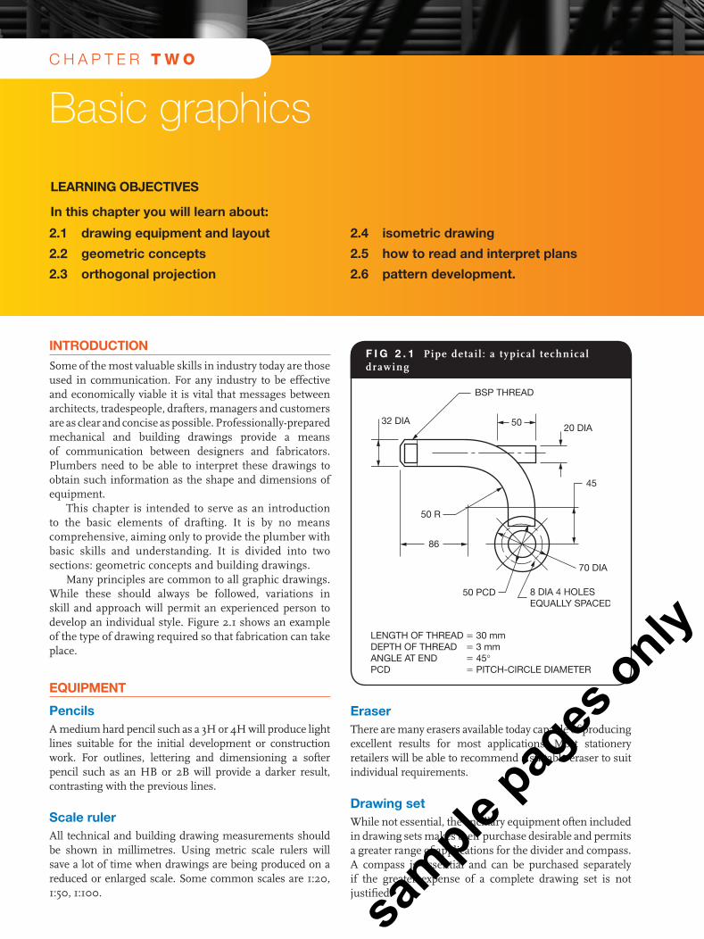
LayoutCare should be taken with a drawing in relation to the position of the main object, dimensions, lettering and title block. The drawing should be centrally-positioned on the sheet with sufficient room between the drawing and the edge of the sheet to allow for dimensions and lettering to be included. The title block is usually located towards the bottom right-hand corner of a drawing sheet.
Drawing boardsThese vary in size, but should be large enough to accommodate the drawing sheet to be used. The left-hand and right-hand edges of the board must be perfectly straight to allow accuracy when using a T square, and the board’s surface should be smooth and flat. A backing sheet should always be placed under the drawing sheet and both sheets should be held in place with masking tape or fastening clips. The use of drawing pins to secure drawing sheets is not recommended.
t squareAn accurate T square with a transparent working edge provides a good basis for any technical drawing. The T square can be used to produce horizontal, parallel lines, or by placing a set square against the working edge, accurate vertical or oblique lines. The plastic edge should be protected against damage at all times as every indentation will show up on the drawing sheet.
set squaresThe two most commonly used set squares are the 30° # 60° and the 45°. The clear plastic type with dimensions printed on the surface is the most suitable. Set square edges can easily be damaged so they require care both while being used and in storage. Regular cleaning will eliminate uneven linework and help to keep the drawing sheet clean. To obtain angles not available by the use of set squares a protractor is used.
Lettering guideAny drafters who are regularly required to include lettering on drawings should use a lettering guide. This instrument allows parallel guide lines for lettering to be drawn quickly and accurately to a variety of dimensions. Instructions on how to use the instrument will accompany any good lettering guide.
F i g 2 . 2 Drawing board, T square, set square and drawing sheet held down with masking tape
F i g 2 . 3 Drawing sheet showing locat ion of t i t le block with minimum detai l
TITLE OF DRAWING
NAME OF FIRM OR DEPARTMENT
DRAWINGJOB No.
SHEET No.
INITIALS OFDRAFTERSCALES
DATE
Alternativeposition ofTitle block
MARGIN
DRAWING SHEET
25
Puffett_Ch02.indd 25 24/09/11 12:58 AM
sample
pages
only
b a s i c g r a p h i c s
Sometimes the title block may extend right across the base of a drawing sheet or vertically down the right-hand side. The title block should contain the following information:
• title of drawing
• name of firm or department
• drawing job number
• sheet number
• scale
• initials of drafter and date
• date drawn or amended.
geometric conceptsAn understanding of basic geometric concepts will provide a good foundation for the development of graphic skills. Familiarity with geometric shapes or forms permit the easy recognition of solid forms from which geometric objects are made or developed.
plane figures
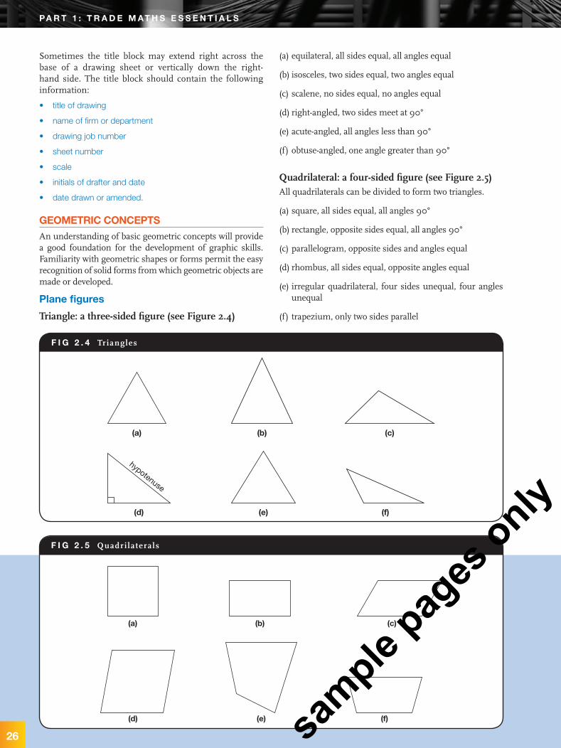
Triangle: a three-sided figure (see Figure 2.4)
(a) equilateral, all sides equal, all angles equal
(b) isosceles, two sides equal, two angles equal
(c) scalene, no sides equal, no angles equal
(d) right-angled, two sides meet at 90°
(e) acute-angled, all angles less than 90°
(f) obtuse-angled, one angle greater than 90°
Quadrilateral: a four-sided figure (see Figure 2.5)All quadrilaterals can be divided to form two triangles.
(a) square, all sides equal, all angles 90°
(b) rectangle, opposite sides equal, all angles 90°
(c) parallelogram, opposite sides and angles equal
(d) rhombus, all sides equal, opposite angles equal
(e) irregular quadrilateral, four sides unequal, four angles unequal
(f) trapezium, only two sides parallel
F i g 2 . 4 Triangles
(a) (b) (c)
(d) (e) (f)
hypotenuse
F i g 2 . 5 Quadri laterals
(a) (b) (c)
(d) (e) (f)
26
pa r t 1 : t r a D e m at h s e s s e n t i a L s
Puffett_Ch02.indd 26 24/09/11 12:58 AM
sample
pages
only
C H A P T E R 2b a s i c g r a p h i c s
27
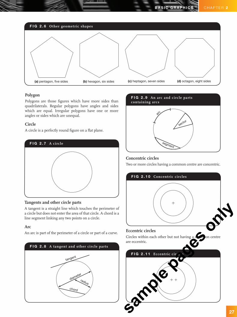
PolygonPolygons are those figures which have more sides than quadrilaterals. Regular polygons have angles and sides which are equal. Irregular polygons have one or more angles or sides which are unequal.
CircleA circle is a perfectly round figure on a flat plane.
tangent
diameter
radius
chord
F i g 2 . 6 Other geometric shapes
(a) pentagon, five sides (b) hexagon, six sides (c) heptagon, seven sides (d) octagon, eight sides
arc
sector
segment
Concentric circlesTwo or more circles having a common centre are concentric.
Tangents and other circle partsA tangent is a straight line which touches the perimeter of a circle but does not enter the area of that circle. A chord is a line segment linking any two points on a circle.
ArcAn arc is part of the perimeter of a circle or part of a curve. Eccentric circles
Circles within each other but not having a common centre are eccentric.
F i g 2 . 7 A circle
F i g 2 . 8 A tangent and other c irc le parts
F i g 2 . 9 An arc and circ le parts containing arcs
F i g 2 . 1 0 Concentric c irc les
F i g 2 . 1 1 Eccentric c irc les
Puffett_Ch02.indd 27 24/09/11 12:58 AM
sample
pages
only
b a s i c g r a p h i c s
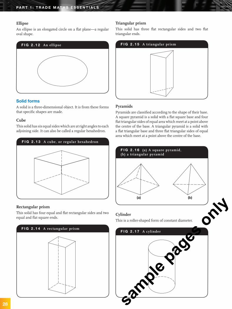
EllipseAn ellipse is an elongated circle on a flat plane—a regular oval shape.
Triangular prismThis solid has three flat rectangular sides and two flat triangular ends.
(a) (b)
solid formsA solid is a three-dimensional object. It is from these forms that specific shapes are made.
CubeThis solid has six equal sides which are at right angles to each adjoining side. It can also be called a regular hexahedron.
Rectangular prismThis solid has four equal and flat rectangular sides and two equal and flat square ends.
PyramidsPyramids are classified according to the shape of their base. A square pyramid is a solid with a flat square base and four flat triangular sides of equal area which meet at a point above the centre of the base. A triangular pyramid is a solid with a flat triangular base and three flat triangular sides of equal area which meet at a point above the centre of the base.
CylinderThis is a roller-shaped form of constant diameter.
28
F i g 2 . 1 2 An el l ipse
F i g 2 . 1 3 A cube, or regular hexahedron
F i g 2 . 1 4 A rectangular prism
F i g 2 . 1 5 A tr iangular prism
F i g 2 . 1 6 (a) A square pyramid, (b) a tr iangular pyramid
F i g 2 . 1 7 A cyl inder
pa r t 1 : t r a D e m at h s e s s e n t i a L s
Puffett_Ch02.indd 28 24/09/11 12:58 AM
sample
pages
only

C H A P T E R 2b a s i c g r a p h i c s
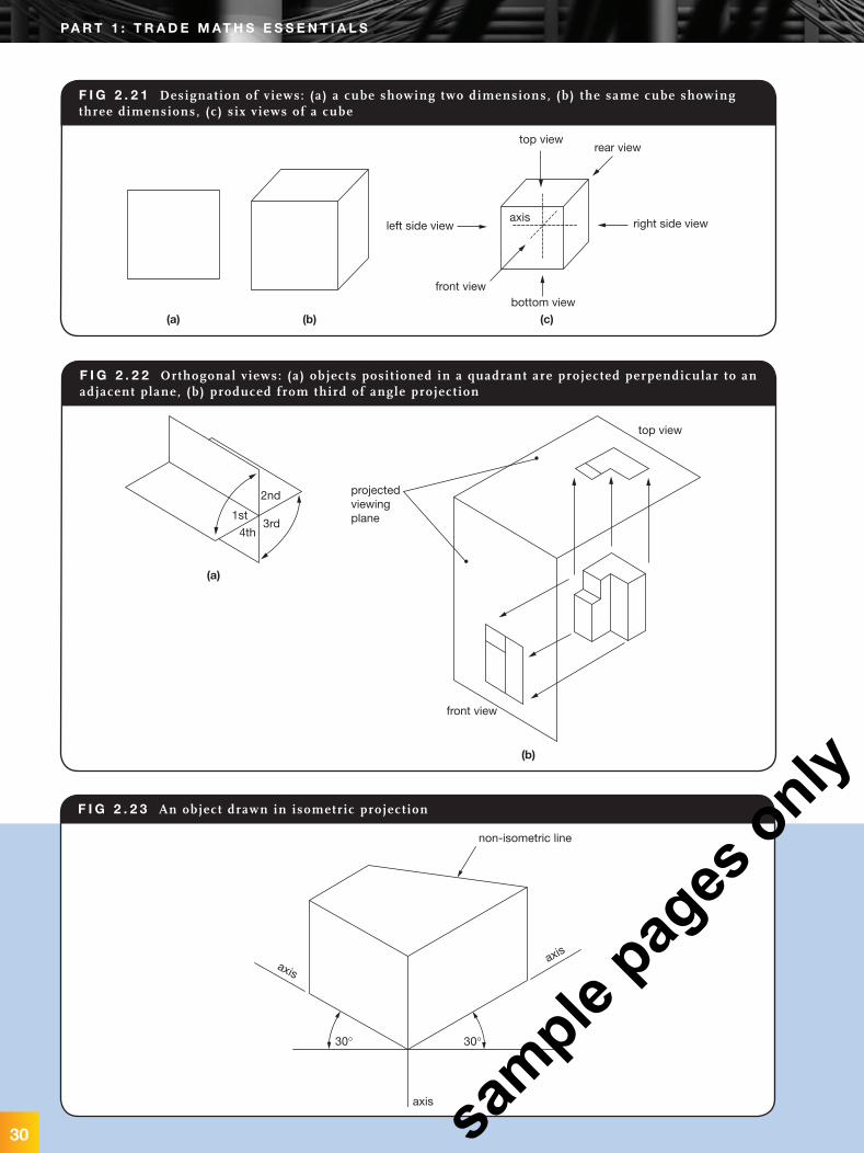
orthogonal or orthographic projectionThe drawing of an object can be achieved in many different ways. A single view may show three dimensions, or several views may be drawn, showing the dimensions as seen from various positions.
If we viewed a cube from a position where only two dimensions were visible, we would be viewing the cube perpendicularly (at right angles) to the plane or surface which is visible. The planes adjacent to the surface we are viewing would also be perpendicular to the visible plane. As we draw each visible plane, we are drawing an orthogonal projection—that is, a view that is perpendicular to the visible surface plane, but which only shows two dimensions of an object.
Of the six views available, only three are usually employed. These are the top side, the front side and the right side views. This method of drawing an object is known as ‘orthogonal projection’. ‘Third angle projection’ (Figure 2.22) is recommended as the standard method of orthogonal projection. In this method of drawing, the object is placed below or behind the plane on which the drawing is produced.
isometric drawingAn isometric drawing (Figure 2.23) shows three sides of an object with lines being drawn to actual length or to an even scale. A T square and a 30° # 60° set square are required for isometric work. The base or axis lines are drawn at 30° to the horizontal while vertical lines remain the same. Lines which are not parallel to vertical lines or axis lines are called ‘non-isometric’ lines. Isometric drawings are not confined to rectangular objects. The flat circular end of an object will
SphereThis is a circular solid of constant diameter. All diameters taken from any point on the surface and passing through the centre are equal.
F i g 2 . 2 0 Orthogonal project ion: third angle
top view
right side view rear view bottom view
left side view front view
ConeThis solid has a flat circular base and a curved side rising to a point above the centre of the base.
F i g 2 . 1 8 A cone
F i g 2 . 1 9 A sphere
29
Puffett_Ch02.indd 29 24/09/11 12:58 AM
sample
pages
only
b a s i c g r a p h i c s
F i g 2 . 2 1 Designation of v iews: (a) a cube showing two dimensions, (b) the same cube showing three dimensions, (c) s ix v iews of a cube
(a) (b) (c)
top viewrear view
right side viewleft side view
front viewbottom view
axis
F i g 2 . 2 2 Orthogonal v iews: (a) objects posi t ioned in a quadrant are projected perpendicular to an adjacent plane, (b) produced from third of angle project ion
1st
2nd
3rd4th
(a)
(b)
projectedviewingplane
top view
front view
30°30°
axis
axis
axis
non-isometric line
F i g 2 . 2 3 An object drawn in isometric project ion
30
pa r t 1 : t r a D e m at h s e s s e n t i a L s
Puffett_Ch02.indd 30 24/09/11 12:58 AM
sample
pages
only
C H A P T E R 2b a s i c g r a p h i c s
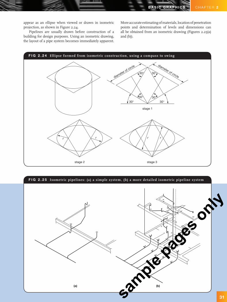
F i g 2 . 2 4 Ell ipse formed from isometric construct ion, using a compass to swing
r r r r
stage 3
stage 1
diameter of circlediameter of circle
30° 30°30°30°
30° 30°
stage 2
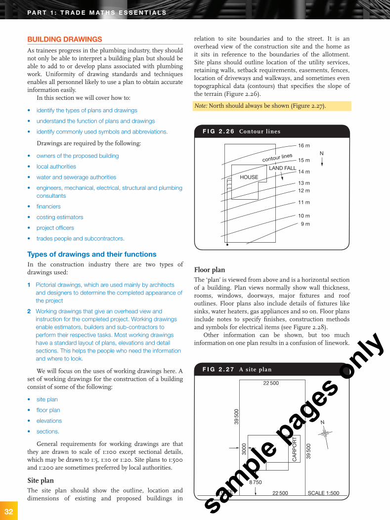
F i g 2 . 2 5 Isometric pipel ines: (a) a s imple system, (b) a more detai led isometric pipel ine system
(a) (b)
appear as an ellipse when viewed or drawn in isometric projection, as shown in Figure 2.24.
Pipelines are usually drawn before construction of a building for design purposes. Using an isometric drawing, the layout of a pipe system becomes immediately apparent.
More accurate estimating of materials, location of penetration points and determination of levels and dimensions can all be obtained from an isometric drawing (Figures 2.25(a) and (b)).
31
Puffett_Ch02.indd 31 24/09/11 12:58 AM
sample
pages
only
b a s i c g r a p h i c s
32
buiLDing DrawingsAs trainees progress in the plumbing industry, they should not only be able to interpret a building plan but should be able to add to or develop plans associated with plumbing work. Uniformity of drawing standards and techniques enables all personnel likely to use a plan to obtain accurate information easily.
In this section we will cover how to:
• identify the types of plans and drawings
• understand the function of plans and drawings
• identify commonly used symbols and abbreviations.
Drawings are required by the following:
• owners of the proposed building
• local authorities
• water and sewerage authorities
• engineers, mechanical, electrical, structural and plumbing consultants
• financiers
• costing estimators
• project officers
• trades people and subcontractors.
types of drawings and their functionsIn the construction industry there are two types of drawings used:
1 Pictorial drawings, which are used mainly by architects and designers to determine the completed appearance of the project
2 Working drawings that give an overhead view and instruction for the completed project. Working drawings enable estimators, builders and sub-contractors to perform their respective tasks. Most working drawings have a standard layout of plans, elevations and detail sections. This helps the people who need the information and where to look.
We will focus on the uses of working drawings here. A set of working drawings for the construction of a building consist of some of the following:
• site plan
• floor plan
• elevations
• sections.
General requirements for working drawings are that they are drawn to scale of 1:100 except sectional details, which may be drawn to 1:5, 1:10 or 1:20. Site plans to 1:500 and 1:200 are sometimes preferred by local authorities.
Site planThe site plan should show the outline, location and dimensions of existing and proposed buildings in
relation to site boundaries and to the street. It is an overhead view of the construction site and the home as it sits in reference to the boundaries of the allotment. Site plans should outline location of the utility services, retaining walls, setback requirements, easements, fences, location of driveways and walkways, and sometimes even topographical data (contours) that specifies the slope of the terrain (Figure 2.26).
Note: North should always be shown (Figure 2.27).
22 500
N
22 500
3950
0
3950
0
CA
RP
OR
T
STREET SCALE 1:500
8 750
3000
HOUSE
16 m
15 m
14 m
13 m12 m
11 m
10 m
9 m
N
LAND FALL
contour lines
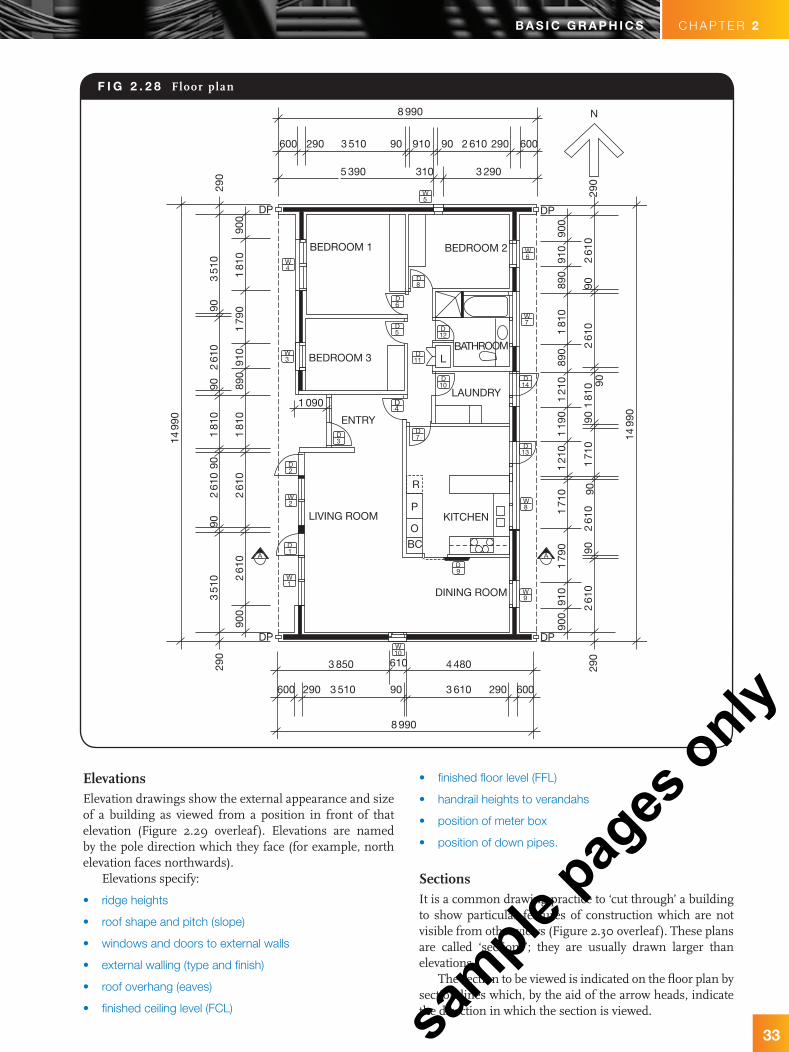
Floor planThe ‘plan’ is viewed from above and is a horizontal section of a building. Plan views normally show wall thickness, rooms, windows, doorways, major fixtures and roof outlines. Floor plans also include details of fixtures like sinks, water heaters, gas appliances and so on. Floor plans include notes to specify finishes, construction methods and symbols for electrical items (see Figure 2.28).
Other information can be shown, but too much information on one plan results in a confusion of linework.
F i g 2 . 2 6 Contour l ines
F i g 2 . 2 7 A si te plan
pa r t 1 : t r a D e m at h s e s s e n t i a L s
Puffett_Ch02.indd 32 24/09/11 12:58 AM
sample
pages
only
C H A P T E R 2b a s i c g r a p h i c s
33
• finished floor level (FFL)
• handrail heights to verandahs
• position of meter box
• position of down pipes.
SectionsIt is a common drawing practice to ‘cut through’ a building to show particular features of construction which are not visible from other views (Figure 2.30 overleaf). These plans are called ‘sections’; they are usually drawn larger than elevations.
The section to be viewed is indicated on the floor plan by section lines which, by the aid of the arrow heads, indicate the direction in which the section is viewed.
ElevationsElevation drawings show the external appearance and size of a building as viewed from a position in front of that elevation (Figure 2.29 overleaf). Elevations are named by the pole direction which they face (for example, north elevation faces northwards).
Elevations specify:
• ridge heights
• roof shape and pitch (slope)
• windows and doors to external walls
• external walling (type and finish)
• roof overhang (eaves)
• finished ceiling level (FCL)
F i g 2 . 2 8 Floor plan
8 990 N
2 610 29091090 903 510
5 390
BEDROOM 1
BEDROOM 3
BEDROOM 2
BATHROOM
ENTRY
L
R
P
O
BC
LAUNDRY
LIVING ROOM KITCHEN
DINING ROOM
310 3 290
290600 600
1499
0
290
290
DP
DP
900
351
0
900
900
261
02
610
9090
9090
890
910
910
179
0
261
090
261
02
610
261
090
9090
90
171
0
171
0
121
01
190
1499
0
121
089
01
810
181
0
890
910
900
290
290
179
0
181
02
610
261
03
510
181
01
810
4 480
3 610 290903 510
3 850 610
8 990
290600 600
DP
DP
1 090
10W
1W
1D
9D
2W
2D
4W
4D
5D
11D
10D
12D
5W
8D
6W
7W
14D
13D
6D
3W
3D 7
D
8W
9W
AA
Puffett_Ch02.indd 33 24/09/11 12:58 AM
sample
pages
only

34
b a s i c g r a p h i c spa r t 1 : t r a D e m at h s e s s e n t i a L s
It is very important to check the title block to ensure the latest version of the drawing is being used to make sure all amendments are noted.
The sectional elevation shows:
• height above ground level (GL)
• ceiling height
• depth of footing
• roof construction and pitch.
Title blockThe title block gives a professional appearance to printed plans and provides important document information. Title blocks are usually located at the bottom right-hand corner of the drawing (Figure 2.31).
Title block includes:
• plan name
• designer name
• project title
• building address
• date printed
• drawing number
• page number (when there is a set of drawings)
• signature of approving authority
• date of amendment
• scale.
F i g 2 . 2 9 Elevat ions
2400
2090
2400
1490
119020
90
EAST ELEVATION
WEST ELEVATION
F i g 2 . 3 0 A cross-sect ion A–A. See Figure 2.8
CEILING
2090
2400
HEAD
FLOOR
Client:
D.C. Brown
Project:
Proposed Child Care Centre
Location:
21 Drive RoadHappy View SA 5000
Project Consultants:
Black and Blue Consultants
Drawn: A.D. Checked:J.B.
Architect:
B.E. Sharp
Issue: A
Scale: 1:100 Date: March 2011
Project No:BCA- 652
Drawing No. WD- 03
F i g 2 . 3 1 Typical t i t le block
pa r t 1 : t r a D e m at h s e s s e n t i a L s
Puffett_Ch02.indd 34 24/09/11 12:58 AM
sample
pages
only
C H A P T E R 2b a s i c g r a p h i c s
35
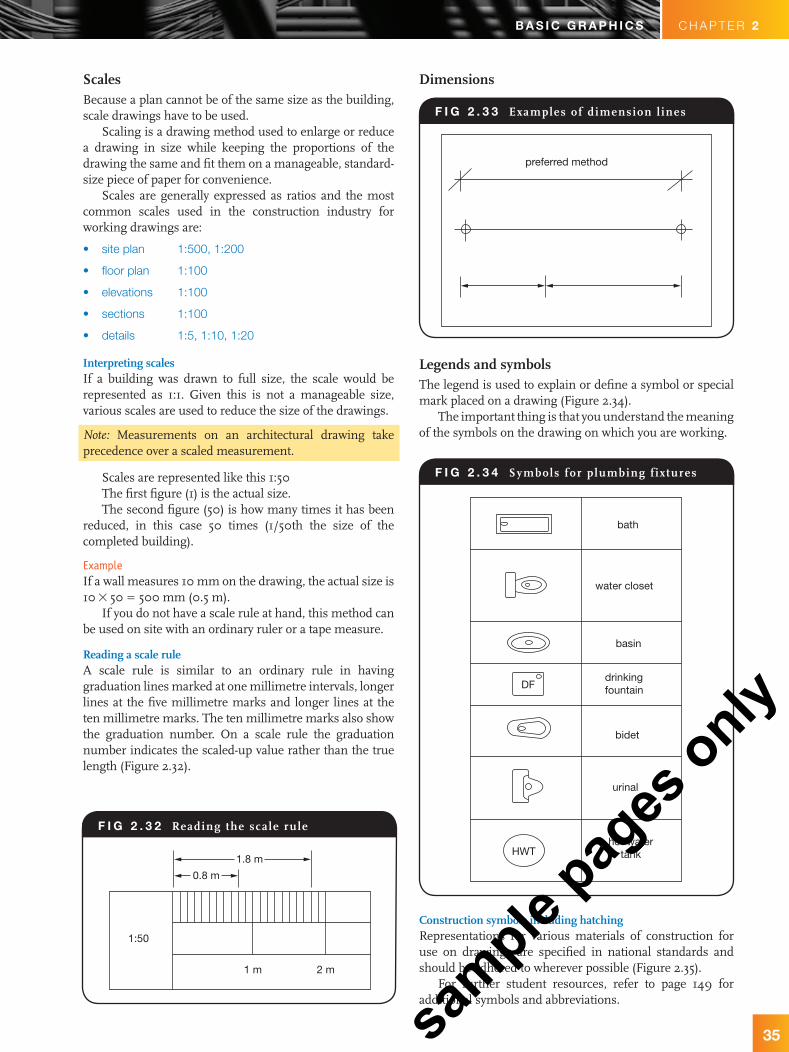
Legends and symbolsThe legend is used to explain or define a symbol or special mark placed on a drawing (Figure 2.34).
The important thing is that you understand the meaning of the symbols on the drawing on which you are working.
ScalesBecause a plan cannot be of the same size as the building, scale drawings have to be used.
Scaling is a drawing method used to enlarge or reduce a drawing in size while keeping the proportions of the drawing the same and fit them on a manageable, standard-size piece of paper for convenience.
Scales are generally expressed as ratios and the most common scales used in the construction industry for working drawings are:
• site plan 1:500, 1:200
• floor plan 1:100
• elevations 1:100
• sections 1:100
• details 1:5, 1:10, 1:20
Interpreting scalesIf a building was drawn to full size, the scale would be represented as 1:1. Given this is not a manageable size, various scales are used to reduce the size of the drawings.
Note: Measurements on an architectural drawing take precedence over a scaled measurement.
Scales are represented like this 1:50The first figure (1) is the actual size.The second figure (50) is how many times it has been
reduced, in this case 50 times (1/50th the size of the completed building).
ExampleIf a wall measures 10 mm on the drawing, the actual size is 10 # 50 = 500 mm (0.5 m).
If you do not have a scale rule at hand, this method can be used on site with an ordinary ruler or a tape measure.
Reading a scale ruleA scale rule is similar to an ordinary rule in having graduation lines marked at one millimetre intervals, longer lines at the five millimetre marks and longer lines at the ten millimetre marks. The ten millimetre marks also show the graduation number. On a scale rule the graduation number indicates the scaled-up value rather than the true length (Figure 2.32).
Dimensions
1.8 m
0.8 m
1:50
1 m 2 m
preferred method
bath
water closet
basin
drinkingfountainDF
HWT
bidet
urinal
hot watertank
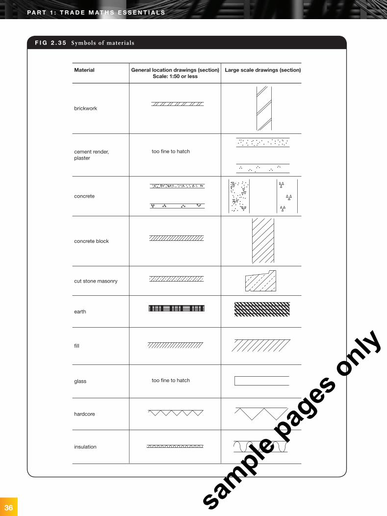
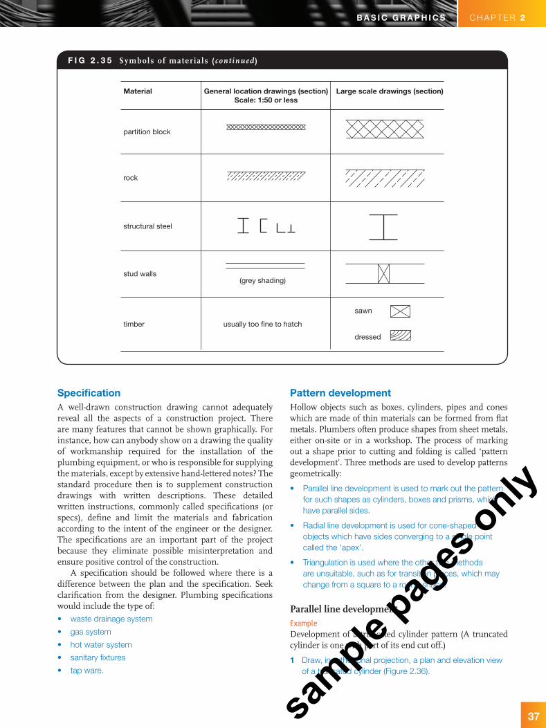
Construction symbols including hatchingRepresentations for various materials of construction for use on drawings are specified in national standards and should be adhered to wherever possible (Figure 2.35).
For further student resources, refer to page 149 for additional symbols and abbreviations.
F i g 2 . 3 2 Reading the scale rule
F i g 2 . 3 3 Examples of dimension l ines
F i g 2 . 3 4 Symbols for plumbing fixtures
Puffett_Ch02.indd 35 24/09/11 12:58 AM
sample
pages
only
36
b a s i c g r a p h i c s
too fine to hatch
too fine to hatch
brickwork
Material General location drawings (section)Scale: 1:50 or less
Large scale drawings (section)
cement render,plaster
concrete
concrete block
cut stone masonry
earth
fill
glass
hardcore
insulation
F i g 2 . 3 5 Symbols of materials
pa r t 1 : t r a D e m at h s e s s e n t i a L s
Puffett_Ch02.indd 36 24/09/11 12:58 AM
sample
pages
only
C H A P T E R 2b a s i c g r a p h i c s
37
specificationA well-drawn construction drawing cannot adequately reveal all the aspects of a construction project. There are many features that cannot be shown graphically. For instance, how can anybody show on a drawing the quality of workmanship required for the installation of the plumbing equipment, or who is responsible for supplying the materials, except by extensive hand-lettered notes? The standard procedure then is to supplement construction drawings with written descriptions. These detailed written instructions, commonly called specifications (or specs), define and limit the materials and fabrication according to the intent of the engineer or the designer. The specifications are an important part of the project because they eliminate possible misinterpretation and ensure positive control of the construction.
A specification should be followed where there is a difference between the plan and the specification. Seek clarification from the designer. Plumbing specifications would include the type of:
• waste drainage system
• gas system
• hot water system
• sanitary fixtures
• tap ware.
partition block
Material General location drawings (section)Scale: 1:50 or less
Large scale drawings (section)
rock
structural steel
stud walls(grey shading)
usually too fine to hatch
sawn
dressed
timber
F i g 2 . 3 5 Symbols of materials (cont inued )
pattern developmentHollow objects such as boxes, cylinders, pipes and cones which are made of thin materials can be formed from flat metals. Plumbers often produce shapes from sheet metals, either on-site or in a workshop. The process of marking out a shape prior to cutting and folding is called ‘pattern development’. Three methods are used to develop patterns geometrically:
• Parallel line development is used to mark out the pattern for such shapes as cylinders, boxes and prisms, which have parallel sides.
• Radial line development is used for cone-shaped objects which have sides converging to a single point called the ‘apex’.
• Triangulation is used where the other two methods are unsuitable, such as for transition pieces, which may change from a square to a round shape.
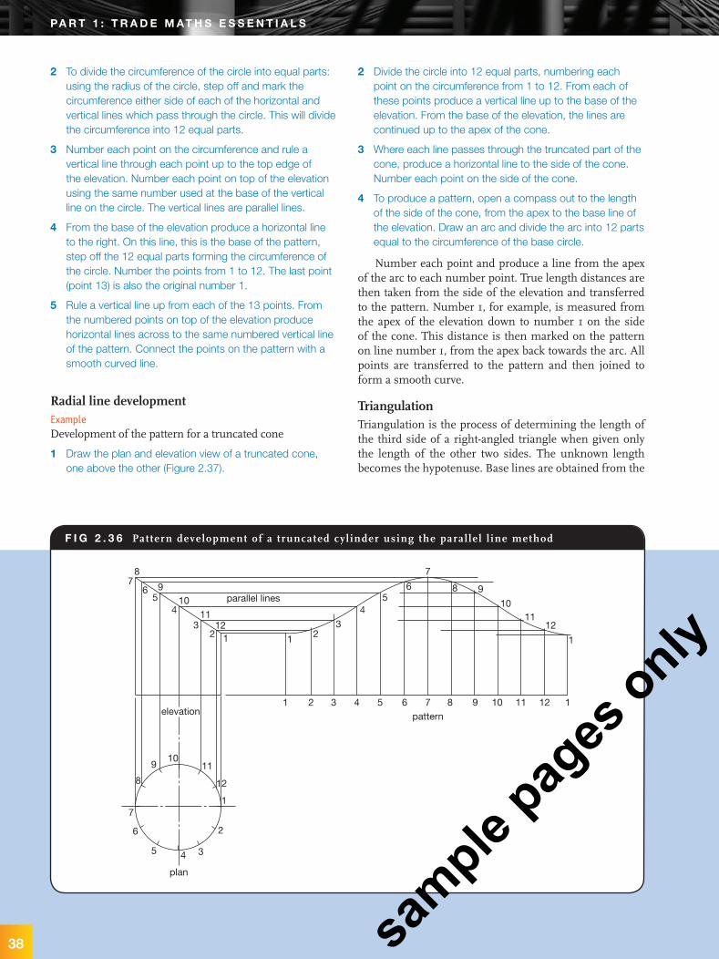
Parallel line developmentExampleDevelopment of a truncated cylinder pattern (A truncated cylinder is one with part of its end cut off.)
1 Draw, in orthogonal projection, a plan and elevation view of a truncated cylinder (Figure 2.36).
Puffett_Ch02.indd 37 24/09/11 12:58 AM
sample
pages
only
b a s i c g r a p h i c s
2 To divide the circumference of the circle into equal parts: using the radius of the circle, step off and mark the circumference either side of each of the horizontal and vertical lines which pass through the circle. This will divide the circumference into 12 equal parts.
3 Number each point on the circumference and rule a vertical line through each point up to the top edge of the elevation. Number each point on top of the elevation using the same number used at the base of the vertical line on the circle. The vertical lines are parallel lines.
4 From the base of the elevation produce a horizontal line to the right. On this line, this is the base of the pattern, step off the 12 equal parts forming the circumference of the circle. Number the points from 1 to 12. The last point (point 13) is also the original number 1.
5 Rule a vertical line up from each of the 13 points. From the numbered points on top of the elevation produce horizontal lines across to the same numbered vertical line of the pattern. Connect the points on the pattern with a smooth curved line.
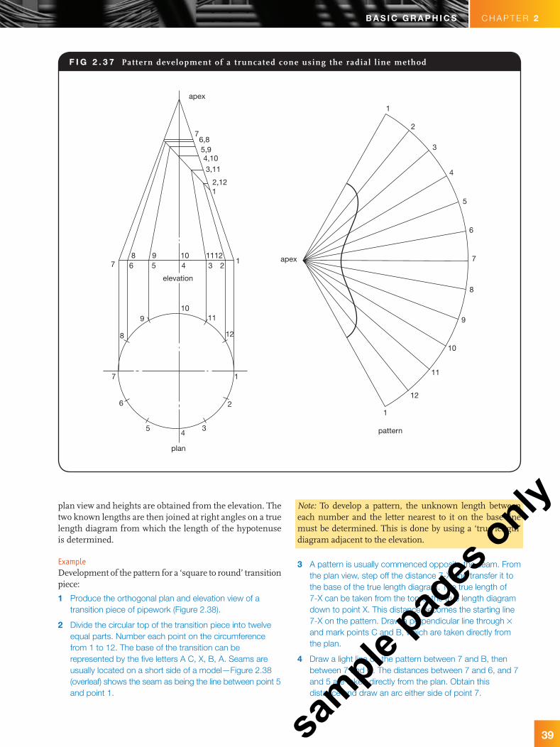
Radial line developmentExampleDevelopment of the pattern for a truncated cone
1 Draw the plan and elevation view of a truncated cone, one above the other (Figure 2.37).
2 Divide the circle into 12 equal parts, numbering each point on the circumference from 1 to 12. From each of these points produce a vertical line up to the base of the elevation. From the base of the elevation, the lines are continued up to the apex of the cone.
3 Where each line passes through the truncated part of the cone, produce a horizontal line to the side of the cone. Number each point on the side of the cone.
4 To produce a pattern, open a compass out to the length of the side of the cone, from the apex to the base line of the elevation. Draw an arc and divide the arc into 12 parts equal to the circumference of the base circle.
Number each point and produce a line from the apex of the arc to each number point. True length distances are then taken from the side of the elevation and transferred to the pattern. Number 1, for example, is measured from the apex of the elevation down to number 1 on the side of the cone. This distance is then marked on the pattern on line number 1, from the apex back towards the arc. All points are transferred to the pattern and then joined to form a smooth curve.
TriangulationTriangulation is the process of determining the length of the third side of a right-angled triangle when given only the length of the other two sides. The unknown length becomes the hypotenuse. Base lines are obtained from the
F i g 2 . 3 6 Pattern development of a truncated cyl inder using the paral le l l ine method
parallel lines10
10
10
10
11
11
11
11
12
12
12
12
1
1
1
1
1
1
2
2
elevation
2
2
3
3
3
3
4
4
plan
4
4
5
5
5
5
6
6
6
6
7
7
7
7pattern
8
8
8
8
9
9
9
9
38
pa r t 1 : t r a D e m at h s e s s e n t i a L s
Puffett_Ch02.indd 38 24/09/11 12:58 AM
sample
pages
only
C H A P T E R 2b a s i c g r a p h i c s
39
F i g 2 . 3 7 Pattern development of a truncated cone using the radial l ine method
apex
76,85,94,103,11
2,121
87 6 5 4 3 2
19 10 1112
elevation
11
12
109
7
6
54
3
2
1
8
apex
1
2
3
4
5
6
7
8
9
10
11
12
1
pattern
plan
plan view and heights are obtained from the elevation. The two known lengths are then joined at right angles on a true length diagram from which the length of the hypotenuse is determined.
ExampleDevelopment of the pattern for a ‘square to round’ transition piece:
1 Produce the orthogonal plan and elevation view of a transition piece of pipework (Figure 2.38).
2 Divide the circular top of the transition piece into twelve equal parts. Number each point on the circumference from 1 to 12. The base of the transition can be represented by the five letters A C, X, B, A. Seams are usually located on a short side of a model—Figure 2.38 (overleaf) shows the seam as being the line between point 5 and point 1.
Note: To develop a pattern, the unknown length between each number and the letter nearest to it on the base line must be determined. This is done by using a ‘true length’ diagram adjacent to the elevation.
3 A pattern is usually commenced opposite the seam. From the plan view, step off the distance 7-X and transfer it to the base of the true length diagram. The true length of 7-X can be taken from the top of the true length diagram down to point X. This distance becomes the starting line 7-X on the pattern. Draw a perpendicular line through # and mark points C and B, which are taken directly from the plan.
4 Draw a light line on the pattern between 7 and B, then between 7 and C. The distances between 7 and 6, and 7 and 5 are taken directly from the plan. Obtain this distance and draw an arc either side of point 7.
Puffett_Ch02.indd 39 24/09/11 12:58 AM
sample
pages
only

40
b a s i c g r a p h i c s
F i g 2 . 3 8 (a) Square to round transit ion piece, (b) pattern development using tr iangulat ion
7 1 1–12
BXC ASD X Belevation true length diagram
B
X
C D
S
A
1
2345
6
7
89
10 1112
plan1
2
3
45
6 7 89
10
11
12
1
S
D
CXB
A
S
(a)
(b)
pattern
For stuDent research• AS 1100 Technical Drawing:
1100.101 Part 101: General principles (1992),1100.201 Part 201: Mechanical
engineering drawing (1992),1100.301 Part 301: Architectural drawing (1985),1100.401 Part 401: Engineering survey and
engineering survey design drawing (1984),1100.501 Part 501: Structural engineering
drawing (1985)
• AS/NZS 3500: 2003 Plumbing and Drainage. Glossary of Terms
5 Measure the distance B-6 from the plan and transfer it to the base of the true length diagram. The true length of B-6 is the distance from the top of the true length diagram to point B; this distance is then transferred to the pattern. Place the compass point on B and draw an arc adjacent to 7 to locate point 6.
Note: There are only three different true lengths for the complete pattern. The numbers 1 to 12 are all equally spaced and taken directly from the plan. The distance between letters on the base line can be taken directly from the plan.
6 Point A is located on the pattern by using the true length diagram. Find the true length of 4-A and from point 4 draw an arc. Take the distance B-A from the plan and draw an arc from B to determine point A. The pattern starts and finishes on a seam line.
Note: Follow steps similar to those above to locate all the points.
pa r t 1 : t r a D e m at h s e s s e n t i a L s
Puffett_Ch02.indd 40 24/09/11 12:58 AM
sample
pages
only
C H A P T E R 2b a s i c g r a p h i c s
41
job title: Apprentice
plumber at Select
Solutions, Victoria
Eleri Dear was recently
awarded NMIT’s
Encouragement
Award for being the
runner up of NMIT’s
2010 1st Year
Apprentice of the
Year. As an apprentice
plumber she has dabbled in almost all plumbing jobs and wants to
one day have her own all-female plumbing business.
How did you get into plumbing?They were advertising for girl plumbers and I gave it a go and
I stuck to it. I was doing horse training before for ten years as
I had never been the girl to do an office job, and needed a career
change. I looked at all the different trades out there but a plumber just
gets to do a lot more than a carpenter or electrician does, there is a
lot more variety of work you do. You are never bored when you work!
What is the most difficult aspect of your job?That’s a hard one as everything is pretty tough. The hardest part
for me is just the physical work. You get used to it though. I was
thinking about doing more training to keep up with the boys but
before you know it you just get stronger. From when I first started,
I can tell I am a lot stronger than I used to be.
What is your most memorable experience?I was runner-up for Apprentice of the Year award at the end of last
year. Also just doing a reline of a house on my own—you get really
excited when you do it all on your own!
What has been the worst job you have done so far?I was doing a septic tank and it all poured out and I fell into it.
I stunk of it all day. You expect the worst in plumbing when you’re
working with toilets.
What do you most enjoy about your job?Just working outdoors, except when it’s 2 °C like today, which is
not the best, but every day is different. I have never been bored
once. As much as it’s hard to work in the cold sometimes you just
know tomorrow is not going to be the same as today.
What is it like working in a male-dominated industry? It’s not as bad as everyone thinks. As long as you get along with
guys reasonably well and deal with the common habits of burping
and farting and just being a normal bloke, it’s not that bad. They
don’t pick on you, or don’t act extra nice to you and feel sorry for
you. I get along with all the guys so I wasn’t concerned about it:
I could always stand up for myself.
What kind of job would you want to do in the future?Probably your household jobs, old people’s homes and that kind of
thing. There is a lot of opportunity there as a female as I think they
trust you more. It’s still really early in my apprenticeship and I have
a lot to learn, so I haven’t pinpointed exactly what I want to do but
I probably want to start an all-girls business. It hasn’t been done
and it is something I would want to look into to give other girls a
go. A lot of girls are probably worried about working with so many
guys as well.
Do you have any words of advice for future female plumbers?Just give it a go if you are thinking about it. If you can’t handle the
boys you are in the wrong industry.
e L e r i D e a r
pLumber proFiLe 2.1
Puffett_Ch02.indd 41 24/09/11 12:58 AM
sample
pages
only


![[PPT]PowerPoint Presentation - McGraw Hill Educationhighered.mheducation.com/olc2/dl/953407/Chap003.ppt · Web viewTitle PowerPoint Presentation Author Jagruti Gadekar Last modified](https://img.pdfslide.us/doc/110x75/5ae12dc87f8b9a6e5c8e64db/pptpowerpoint-presentation-mcgraw-hill-viewtitle-powerpoint-presentation-author.jpg)