Embed Size (px)
Citation preview
C-AMTE: A Location Mechanism for Flexible Cache
Management in Chip Multiprocessors
Mohammad Hammoud, Sangyeun Cho, and Rami Melhem
Department of Computer Science
University of Pittsburgh
Abstract
This paper describes Constrained Associative-Mapping-of-Tracking-Entries(C-AMTE), a scalable mechanism to facilitate flexible and efficient distributedcache management in large-scale chip multiprocessors (CMPs). C-AMTEenables fast locating of cache blocks in CMP cache schemes that employone-to-one or one-to-many associative mappings. C-AMTE stores in per-core data structures tracking entries to avoid on-chip interconnect trafficoutburst or long distance directory lookups. Simulation results using a fullsystem simulator demonstrate that C-AMTE achieves improvement in cacheaccess latency by up to 34.4%, close to that of a perfect location strategy.
Key words:
CMP, Shared Scheme, Private Scheme, Associative Mapping, FixedMapping, Tracking Entries.
1. Introduction
Crossing the billion-transistor per chip barrier has had a profound influenceon the emergence of chip multiprocessors (CMPs) as a mainstream archi-tecture of choice. As CMPs’ realm is continuously expanding, they mustprovide high and scalable performance. One of the key challenges to ob-taining high performance from CMPs is the management of the limited on-chip cache resources (typically the L2 cache) shared by multiple executingthreads/processes.
Economic, manufacturing, and physical design considerations suggesttiled CMP architectures (e.g., Tilera’s Tile64 and Intel’s Teraflops Research
Preprint submitted to Journal of Parallel and Distributed Computing November 13, 2010
R
Core
Tag
L2$
L1I$ L1D$
To Memory
R
Core
L2$
R
Core
Dir
Tag
L2$
L1I$ L1D$
Dir
Tag
L2$
L1I$ L1D$
To Memory
R
Core
Tag
L2$
L1I$ L1D$
Dir
Dir
(a) Shared L2 Design (b) Private L2 Design
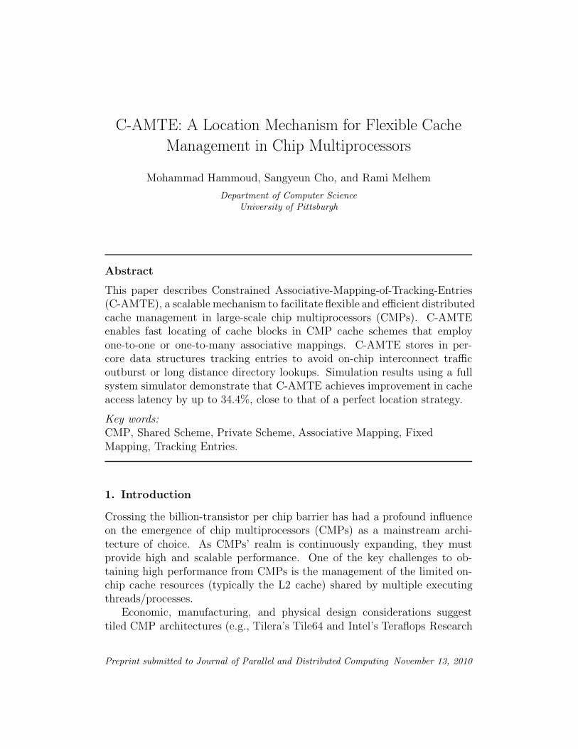
Figure 1: Two traditional cache organizations. (a) The shared L2 design backsup all the L1 caches. (b) The private L2 design backs up only the private L1cache on each tile. (Dir stands for directory and R for router).
Chip) that co-locate distributed cores with distributed cache banks in tilescommunicating via a network on-chip (NoC) [13]. A tile typically includes acore, private L1 caches (I/D), and an L2 cache bank. A traditional practice,referred to as the shared scheme, logically shares the physically distributed L2banks. On-chip access latencies differ depending on the distances betweenrequester cores and target banks creating a Non Uniform Cache Architec-ture (NUCA) [16]. As an example, the Intel CoreTM i7 processor introducesNUCA into its platform [25]. Another conventional practice referred to asthe private scheme, associates each L2 bank to a single core and providesno capacity sharing among cores. Fig. 1 demonstrates the two designs. Forsimplicity we show only a dual-core tiled CMP architecture. In addition, weassume a distributed directory protocol.
The private scheme replicates cache blocks at the L2 banks of the request-ing cores. Hence, an effective cache associativity which equates the aggregateassociativity of the L2 cache banks is provided [6]. That is, a cache block canmap to any of the private L2 banks, and if shared amongst cores, can residein multiple L2 banks. A high bandwidth on-chip directory protocol can beemployed to keep the multiple L2 banks coherent. The directory can be heldas a duplicate set of L2 tags distributed across tiles by set index [2, 32]. Wegenerally refer to a mapping process that exploits the aggregate associativ-ity of the L2 cache banks as an associative mapping strategy. In particular,we designate the mapping strategy of the private scheme as one-to-many
associative mapping because a single block can be mapped to multiple L2banks.
In contrast to the private design, the shared scheme maintains the exclu-
2
siveness of cache blocks at the L2 level. A core maps and locates a cacheblock, B, to and from a target L2 bank at a tile referred to as the static home
tile (SHT) of B. The SHT of B is determined by a subset of bits denoted ashome select bits (or HS bits) from B’s physical address. As such, the sharedstrategy requires maintaining coherence only at the L1 level. The SHT of Bcan store B itself and a bit vector indicating which cores had cached copiesof B in their L1 private caches. This on-chip coherence practice is referredto as an in-cache coherence protocol [5, 12, 32]. In this work we refer to anentry that tracks copies (either at L1 or L2) of a certain cache block as atracking entry. We, furthermore, identify a mapping process that maps anentry (block or tracking) to a fixed tile as a fixed mapping strategy (e.g., theshared design employs fixed mapping).
Recent research work on CMP cache management has recognized theimportance of the shared scheme [27, 12, 11, 14, 29, 15]. Besides, many oftoday’s multi-core processors, the Intel CoreTM2 Duo processor family [22],Sun Niagara [17], and IBM Power5 [26], have featured shared caches. Ashared design, however, suffers from a growing on-chip delay problem. Accesslatencies to L2 banks are non-uniform and proportional to the distancesbetween requester cores and target banks. This drawback is referred to asthe NUCA problem.
To mitigate the NUCA problem, many proposals have extended the nom-inal basic shared design to allow associative mapping (i.e., leveraging theaggregate associativity of the L2 cache banks). For instance, block migra-tion [3, 11, 14, 15, 31] exploits associative mapping by moving frequentlyaccessed blocks closer to requesting cores. We denote such a strategy as one-
to-one associative mapping due to the fact that the exclusiveness of cacheblocks at the L2 level is still preserved (only a single copy of a block is pro-moted along identical sets over different banks). In contrast to migration,replication duplicates cache blocks at different L2 banks [8, 6, 32]. Accord-ingly, a replication scheme is said to adopt one-to-many associative mapping.
A major shortcoming of using associative mapping for blocks in any CMPcache management scheme is the location process. For example, a migrationscheme that promotes a cache block B to a tile different than its home tile,denoted as the current host of B, can’t use anymore the HS bits of B’s phys-ical address to locate B. Consequently, different strategies for the locationprocess need to be considered. A tracking entry can always be retained ata centralized directory or at B’s home tile (if the underlying directory pro-tocol is distributed) to enable tracking B after promotion. Hence, if a core
3
requests B, the repository of the tracking entries is reached first then thequery is forwarded to B’s host tile to satisfy the request. The disadvantageof this option is the arousal of 3-way cache-to-cache transfers which can de-grade the average L2 access latency. An alternative location strategy couldbe to broadcast queries to all the tiles assuming no tracking entry for B iskept at a specific repository. Such a strategy can, however, burden the NoCand potentially degrade the overall system performance.
This paper proposes Constrained Associative-Mapping-of-Tracking-Entries(C-AMTE), a mechanism that flexibly accelerates cache management inCMPs. In particular, C-AMTE presents constrained associative mapping
that combines the effectiveness of both, the associative and fixed mappingstrategies and applies that to tracking entries to resolve the challenge oflocating cache blocks without broadcasting and with minimal 3-way commu-nications.
To summarize, the contributions of C-AMTE are as follows:
• It enables fast location of cache blocks without swamping the NoC.
• It can be applied whenever associative mapping is used for cache blocks,either in case of one-to-one (i.e, migration) or one-to-many (i.e, repli-cation).
• It can be generally applied to cache organizations that extend the con-ventional private or shared schemes. Furthermore, it opens opportu-nities for architects to propose more creative cache management de-signs with no necessity to stick to either private or shared traditionalparadigms.
The rest of the paper is organized as follows. Section 2 presents somerecent CMP cache management schemes. C-AMTE mechanism is detailed inSection 3. In Section 4 we evaluate C-AMTE, and we conclude in Section 5.
2. Related Work
Much work has been done to effectively manage CMP caches. Many propos-als advocate CMP cache management at either fine (block) or coarse (page)granularities and base their work on either the nominal shared or privateschemes. We briefly discuss below some of the prior work and describe thelocation process that each proposal employs. We note that C-AMTE is not
an independent CMP scheme that can be run by itself, but yet a location
4
mechanism that can be applied to CMP designs that employ one-to-one or
one-to-many associative mapping.Beckmann and Wood [3] and Huh et al. [14] studied generational promo-
tion and suggested Dynamic NUCA (DNUCA) that migrates blocks towardsbanks close to requesting processors. To locate migratory blocks, [14] adoptssending concurrent queries to L2 banks. To reduce the number of queriessent over the NoC, [3] staggers the location process by searching L2 bankssequentially in an increasing order of their distances from the requester cores.
Guz et al. [11] presented a new architecture that utilizes migration todivert only shared data to cache banks at the center of the chip close to allthe cores. To locate migratory blocks, sequential, hybrid (between sequentialand broadcast), and sequential with predictor policies have been scrutinized.Kandemir et al. [15] proposed a mechanism that determines a suitable lo-cation for a data block, B, within the shared L2 space at any given pointduring execution and then migrates B to that suitable place. To locate B, amultistep checking scheme was employed.
Zhang and Asanovic [31] examined direct promotion (upon first touch)and proposed Victim Migration that migrates a cache block, B, from its hometile to the initial requester tile. A victim migration (VM) table per each tilewas suggested to keep track of the locations of migratory blocks. Specifically,a migration tag for B is kept in the VM table at B’s home tile to point to thecurrent host of B. Later if a sharer core S reaches the home tile of B and failsto find a matching tag in the regular L2 tag array but hits in the associatedVM table, the current host of B, pointed out by the matched migration tag,satisfies the request using a 3-way cache-to-cache transfer. Clearly, VictimMigration fails to exploit distance locality. That is, the request of a sharercore S might incur significant latency to locate B (due to approaching B’shome tile), though B might reside in close proximity to S.
Marty and Hill [19] proposed imposing a two-level virtual coherence hier-archy on a physically flat CMP that harmonizes with virtual machines (VMs)assignments. A key challenge for an intra-VM protocol is to find the hometile of a requested block. For an intra-VM, the home tile is a function of twoproperties: which tiles belong to a VM and how many tiles belong to a VM.Awkwardly, a dynamic VM reassignment can change both. As such, theysuggest co-locating caches with tables within tiles. A table must be lookedup before a miss leaves a tile. Each table includes 64 six-bit entries indexedby the six least-significant bits of the block number. Tables would be set bya hypervisor (or OS) at a VM (or process) reassignment.
5
Hammoud et al. [12] proposed an adaptive controlled migration (ACM)scheme that relies on prediction to collect accessibility information regard-ing cores that accessed a block B in the past, and then assuming that eachof these cores will access B again in the future, dynamically migrates B toa bank that minimizes the overall network hops needed. To locate cacheblocks, the cache-the-cache-tag (CTCT) location policy has been suggested.CTCT is a specific version of the C-AMTE mechanism and had been pre-sented in [12] specifically to perform blocks’ locations for ACM. This papergeneralizes CTCT (now C-AMTE) to enable fast locating of cache blocks inCMP cache schemes that adopt one-to-one (i.e., migration) or one-to-many(i.e., replication) associative mappings.
Cho and Jin [9] proposed an OS-based page allocation algorithm appli-cable to NUCA architectures. Cache blocks are mapped and located to L2banks using interleaving on page frame numbers. Chaudhuri [7] suggestedPageNUCA which employs data migration at page granularity. Hardvellaset al. [13] presented R-NUCA that relies on OS to classify cache accessesinto either private, shared, or instructions and then places and locates eachdifferently at the L2 cache space. Both, PageNUCA and R-NUCA adoptdirect location strategies similar to C-AMTE. In Section 3.5 we detail thetwo schemes and compare and contrast them versus C-AMTE.
Lastly, many researchers explored data replication instead of migrationto mitigate the NUCA latency problem. Zhang and Asanovic [32] proposedvictim replication (VR) scheme based on the nominal shared design. VRkeeps replicas of local primary cache victims within only the local L2 cachebanks. As such, the location process becomes straightforward: local L2banks are looked up (seeking for replica hits) before potentially checkingwith blocks’ home tiles. However, many other cache schemes don’t limitthemselves to replicating blocks at only local L2 banks. Chang and Sohi [6]proposed cooperative caching based on the private scheme, and created aglobally managed shared aggregate on-chip cache. Chisti et al. [8] proposedCMP-NuRAPID that controls replication based on usage patterns. Both, [6]and [8] utilize 3-way cache-to-cache transfers to satisfy L2 requests uponmisses at local L2 banks.
6
3. The Proposed Mechanism
3.1. Description of the Mechanism
Constrained Associative-Mapping-of-Tracking-Entries (C-AMTE) is not anautonomous CMP cache organization that can run by itself but rather amechanism that can be applied to CMP cache designs that employ one-to-one (i.e., migration) or one-to-many (i.e., replication) associative mappings.A shared NUCA architecture maps and locates a cache block, B, to and froma home tile determined by a subset of bits (home select or HS bits) from B’sphysical address. Accordingly, B might be mapped to a bank far away fromthe requester core, causing the core significant latency to locate B. Sucha problem is referred to as the NUCA problem. Migration and replicationhave been suggested as techniques to alleviate the NUCA problem. To savelatency on subsequent requests to B, migration and replication relocate andreplicate, respectively B at a tile different than its home tile, denoted asthe host tile of B, closer to requesting cores. Consequently, B can have, inaddition to the home tile, one or more host tiles. To locate B at a host tile,the HS bits of B’s physical address can’t be used anymore. C-AMTE offersa robust and versatile location strategy to locate B at host tiles.
Assuming a distributed directory protocol, C-AMTE supports storing onetracking entry corresponding to a block B at the home tile of B. We referto this tracking entry as the principal tracking entry. The principal trackingentry points to B and can always be checked by any requester core to locateB at its current host. The principal tracking entry is stored using a fixedmapping strategy because the home tile of B is designated by the HS bits ofB’s physical address. C-AMTE also supports storing another type of trackingentries for B at requester tiles. We refer to this type of tracking entries asreplicated tracking entries. A replicated tracking entry at a requester tile alsopoints to the current host of B but can be rapidly checked by a requestercore to directly locate B (instead of checking with B’s home tile to achievethat). The idea of replicating tracking entries at requester tiles capitalizeson the one-to-many associative mapping strategy traditionally applied forcache blocks. C-AMTE combines associative and fixed mapping strategiesand apply that to tracking entries in order to efficiently solve the locationproblem. Table 1 illustrates the hybrid approach adopted by the C-AMTEmechanism. We refer to such a hybrid mapping process as a constrained
associative mapping strategy.
7
Block Mapping Tracking Entries Mapping
Private Scheme (P) Associative (at requesting tiles) Fixed (at home tiles)
Shared Scheme (S) Fixed (at home tiles) Fixed (at home tiles)
Scheme With C-AMTEAssociative (one-to-one or one-to-many Constrained=Fixed (at home tiles)
depending on the underlying cache scheme) + Associative (at requesting tiles)
Table 1: Mapping strategies of private and shared CMP caches and the hybridmapping approach of C-AMTE.
Based on the above discussion, per each tile, T, a principal trackingentry is kept for each cache block B whose home tile is T but had beenmapped/promoted to another tile. Besides, replicated tracking entries areretained at T to track the locations of other corresponding cache blocks thathave been recently accessed by T but whose home tile is not T. Thoughboth, principal and tracking entries essentially act as pointers to the currenthosts of cache blocks, we differentiate between them for consistency and re-placement purposes (more on this shortly). We can add two distinct datastructures per each tile to store the two types of the tracking entries. A datastructure, referred to as the principal tracking entries (PTR) table, can holdprincipal tracking entries, and a data structure, referred to as the replicatedtracking entries (RTR) table, can hold replicated ones. Alternatively, a singletable, could be referred to as the tracking entries (TR) table, can be addedto hold both classes of tracking entries pertaining that a hardware extension(i.e., an indicative bit) is engaged to distinguish between the two entries.
Assume a CMP organization with PTR and RTR tables. Whenever a coreissues a request to a block B, its RTR table is checked first for a matchingreplicated tracking entry. C-AMTE then proceeds as follows:
• On a miss at the RTR table, the home tile of B is reached and its PTRtable is looked up.
– If a miss occurs at the PTR table, B is fetched from the mainmemory and mapped to a tile T specified by the underlying cachescheme protocol. If T is not B’s home tile, principal and replicatedtracking entries are stored at the PTR table of B’s home tile andthe RTR table of the requester core, respectively. If, in contrary,T is B’s home tile, no tracking entries are kept at either PTR orRTR tables (B can be located directly using the HS bits of B’sphysical address).
– If, on the other hand, a hit occurs at the PTR table, B is locatedat its current host tile and a replicated tracking entry is stored at
8
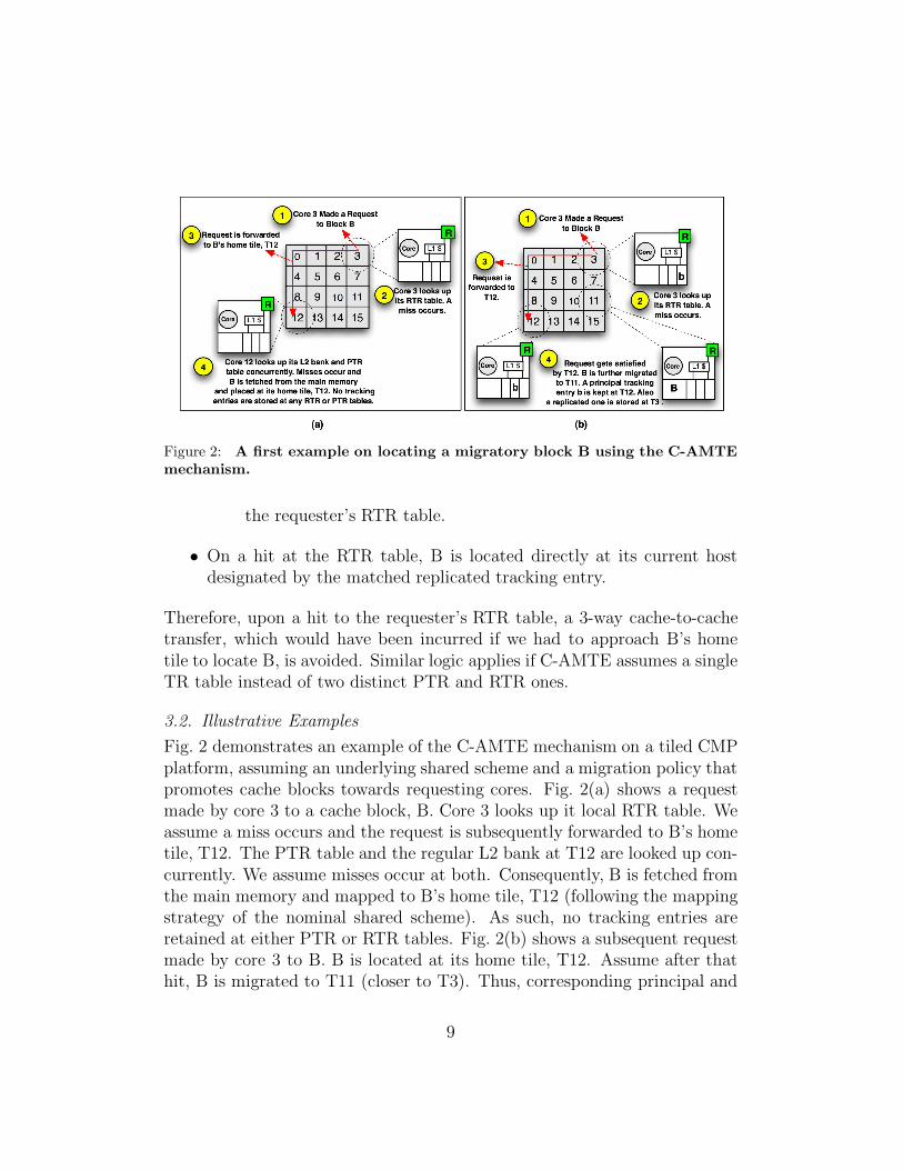
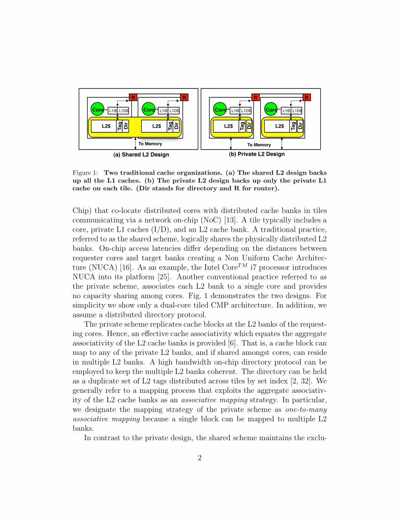
Figure 2: A first example on locating a migratory block B using the C-AMTEmechanism.
the requester’s RTR table.
• On a hit at the RTR table, B is located directly at its current hostdesignated by the matched replicated tracking entry.
Therefore, upon a hit to the requester’s RTR table, a 3-way cache-to-cachetransfer, which would have been incurred if we had to approach B’s hometile to locate B, is avoided. Similar logic applies if C-AMTE assumes a singleTR table instead of two distinct PTR and RTR ones.
3.2. Illustrative Examples
Fig. 2 demonstrates an example of the C-AMTE mechanism on a tiled CMPplatform, assuming an underlying shared scheme and a migration policy thatpromotes cache blocks towards requesting cores. Fig. 2(a) shows a requestmade by core 3 to a cache block, B. Core 3 looks up it local RTR table. Weassume a miss occurs and the request is subsequently forwarded to B’s hometile, T12. The PTR table and the regular L2 bank at T12 are looked up con-currently. We assume misses occur at both. Consequently, B is fetched fromthe main memory and mapped to B’s home tile, T12 (following the mappingstrategy of the nominal shared scheme). As such, no tracking entries areretained at either PTR or RTR tables. Fig. 2(b) shows a subsequent requestmade by core 3 to B. B is located at its home tile, T12. Assume after thathit, B is migrated to T11 (closer to T3). Thus, corresponding principal and
9
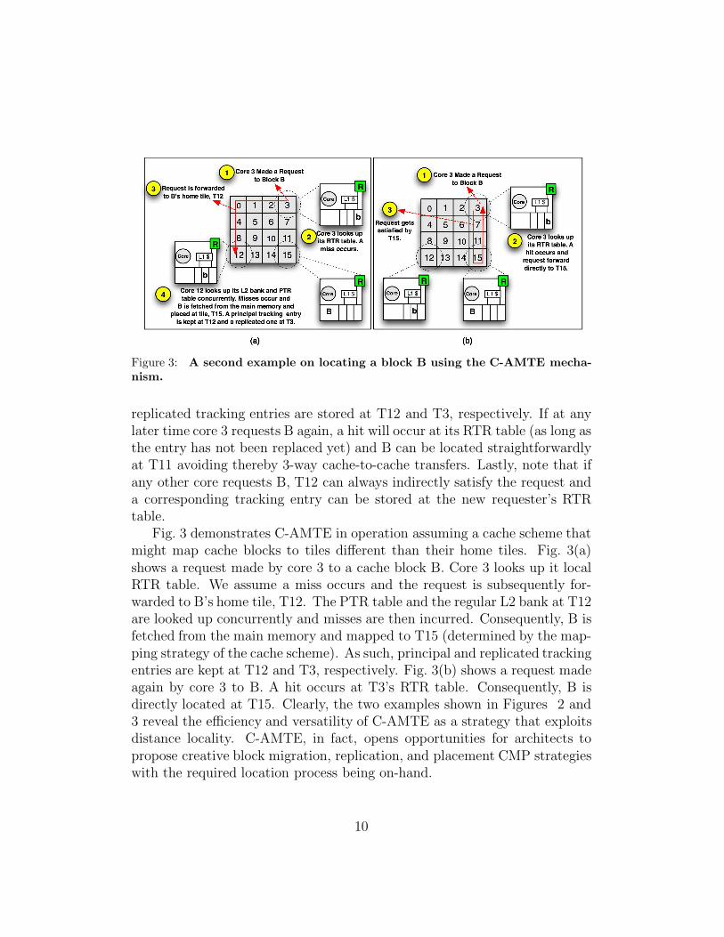
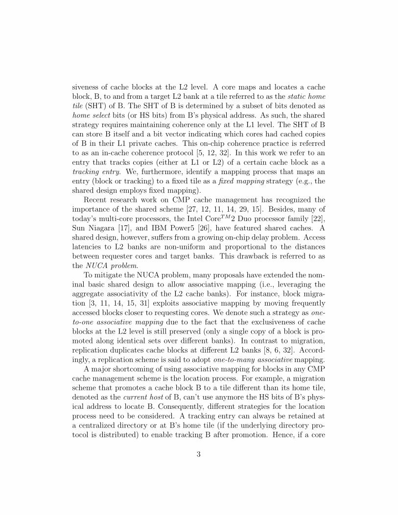
Figure 3: A second example on locating a block B using the C-AMTE mecha-nism.
replicated tracking entries are stored at T12 and T3, respectively. If at anylater time core 3 requests B again, a hit will occur at its RTR table (as long asthe entry has not been replaced yet) and B can be located straightforwardlyat T11 avoiding thereby 3-way cache-to-cache transfers. Lastly, note that ifany other core requests B, T12 can always indirectly satisfy the request anda corresponding tracking entry can be stored at the new requester’s RTRtable.
Fig. 3 demonstrates C-AMTE in operation assuming a cache scheme thatmight map cache blocks to tiles different than their home tiles. Fig. 3(a)shows a request made by core 3 to a cache block B. Core 3 looks up it localRTR table. We assume a miss occurs and the request is subsequently for-warded to B’s home tile, T12. The PTR table and the regular L2 bank at T12are looked up concurrently and misses are then incurred. Consequently, B isfetched from the main memory and mapped to T15 (determined by the map-ping strategy of the cache scheme). As such, principal and replicated trackingentries are kept at T12 and T3, respectively. Fig. 3(b) shows a request madeagain by core 3 to B. A hit occurs at T3’s RTR table. Consequently, B isdirectly located at T15. Clearly, the two examples shown in Figures 2 and3 reveal the efficiency and versatility of C-AMTE as a strategy that exploitsdistance locality. C-AMTE, in fact, opens opportunities for architects topropose creative block migration, replication, and placement CMP strategieswith the required location process being on-hand.
10
3.3. Maintenance and Coherence of the Tracking Entries
The principal and replicated tracking entries need to be kept coherent. Weaccomplish this by embedding a bit vector with each principal tracking entryat the PTR tables to indicate which cores had cached related replicatedtracking entries at their RTR tables (much similar to the in-cache coherenceprotocol in [5]). For instance, given the example depicted in Fig. 2, each timeB is migrated to a different tile, the principal and the replicated trackingentries that correspond to B are updated to point to the new host of B.Besides, C-AMTE can easily preclude potential false misses that can occurwhen L2 requests fail to hit on cache blocks because they are in transitbetween L2 banks. When migration is to be performed, a copy, B’, of thecache block B is kept at the current bank so as if an L2 request arriveswhile B is in transit, the request is immediately satisfied without incurringany delay. When B reaches the new host, an acknowledgement message issent back to the old host to discard B’. The old host keeps track of any tilethat accesses B’, and when receiving the acknowledgment message, sends anupdate message to the new host to indicate the new sharers that requestedB while it was in transit. The directory state entry of B is consecutivelyupdated. Clearly, enforcing coherence among tracking entries and precludingfalse misses impose traffic overhead on the network on-chip. Section 4.2demonstrates the increase in message hops per 1K instructions incurred bythe C-AMTE mechanism.
Finally, PTR and RTR tables can employ the LRU replacement policy.However, in case of a single TR table, it is wise to never evict a principaltracking entry in favor of a replicated one (this is the reason of why wesuggested distinguishing between the two entries). An eviction of a principaltracking entry causes evictions to the corresponding cache block and all therelated replicated tracking entries. Therefore, the TR replacement policyshould replace the following three classes of entries in an ascending order:(1) an invalid entry, (2) an LRU replicated tracking entry, (3) and an LRUprincipal tracking entry. Besides, upon storing a replicated tracking entry,only the first two classes are considered for replacement. If no entry belongingto one of these two classes is detected, a replicated tracking entry is notretained.
3.4. Hardware Cost and Scalability
The storage overhead incurred by C-AMTE pertains to the usage of principaland replicated tracking entries. As described earlier, C-AMTE incurs at least
11
!"
#!"
$!!"
$#!"
%!!"
%#!"
$&" '%" &(" $%)" %#&" #$%" $!%("*"+,
-./01/"23"4,56789"60-7/"
609
0-8:;"
<=>?/."23"@8A/1"
65BC@DEF=AAG" 65BC@DE62>9(G" 65BC@DE62>9)G"
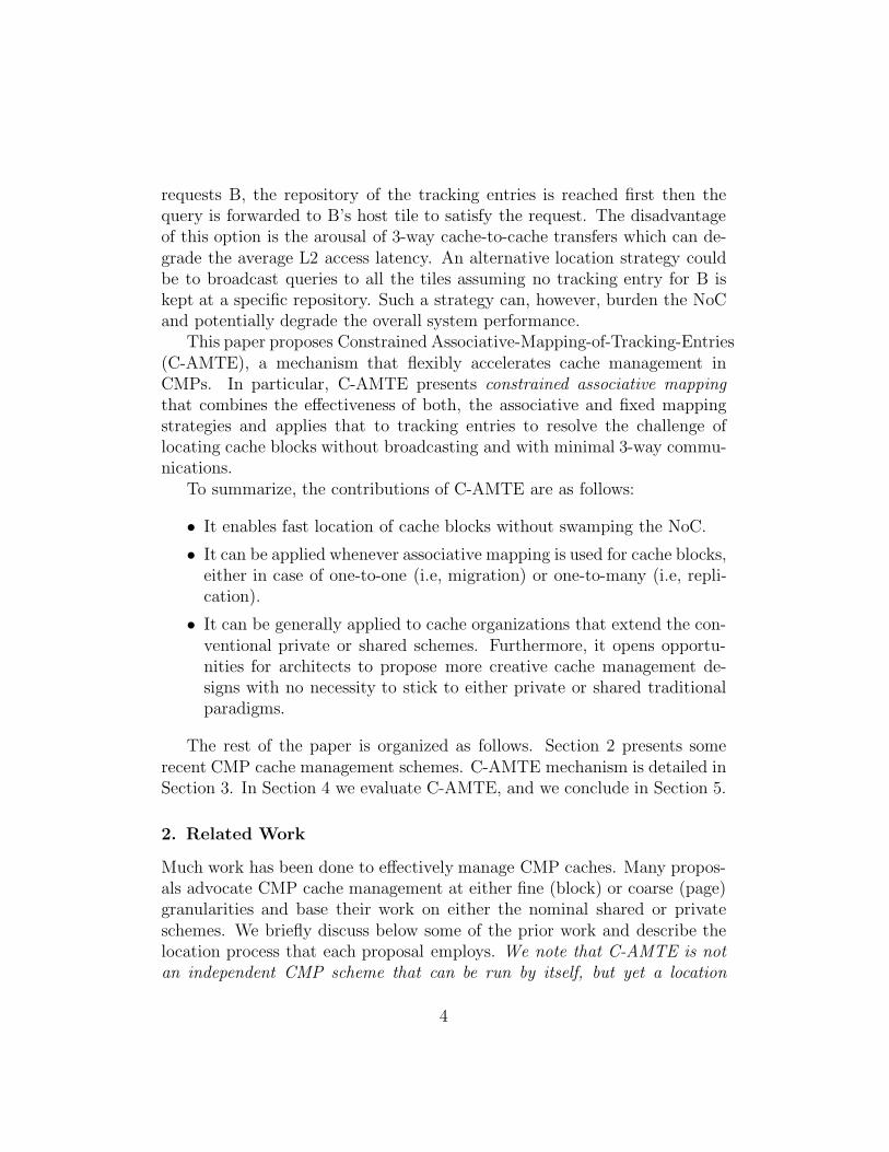
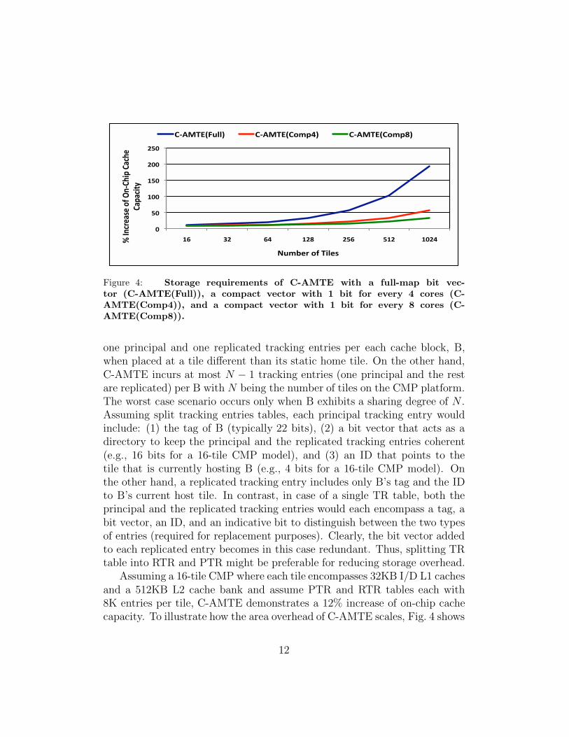
Figure 4: Storage requirements of C-AMTE with a full-map bit vec-tor (C-AMTE(Full)), a compact vector with 1 bit for every 4 cores (C-AMTE(Comp4)), and a compact vector with 1 bit for every 8 cores (C-AMTE(Comp8)).
one principal and one replicated tracking entries per each cache block, B,when placed at a tile different than its static home tile. On the other hand,C-AMTE incurs at most N − 1 tracking entries (one principal and the restare replicated) per B with N being the number of tiles on the CMP platform.The worst case scenario occurs only when B exhibits a sharing degree of N .Assuming split tracking entries tables, each principal tracking entry wouldinclude: (1) the tag of B (typically 22 bits), (2) a bit vector that acts as adirectory to keep the principal and the replicated tracking entries coherent(e.g., 16 bits for a 16-tile CMP model), and (3) an ID that points to thetile that is currently hosting B (e.g., 4 bits for a 16-tile CMP model). Onthe other hand, a replicated tracking entry includes only B’s tag and the IDto B’s current host tile. In contrast, in case of a single TR table, both theprincipal and the replicated tracking entries would each encompass a tag, abit vector, an ID, and an indicative bit to distinguish between the two typesof entries (required for replacement purposes). Clearly, the bit vector addedto each replicated entry becomes in this case redundant. Thus, splitting TRtable into RTR and PTR might be preferable for reducing storage overhead.
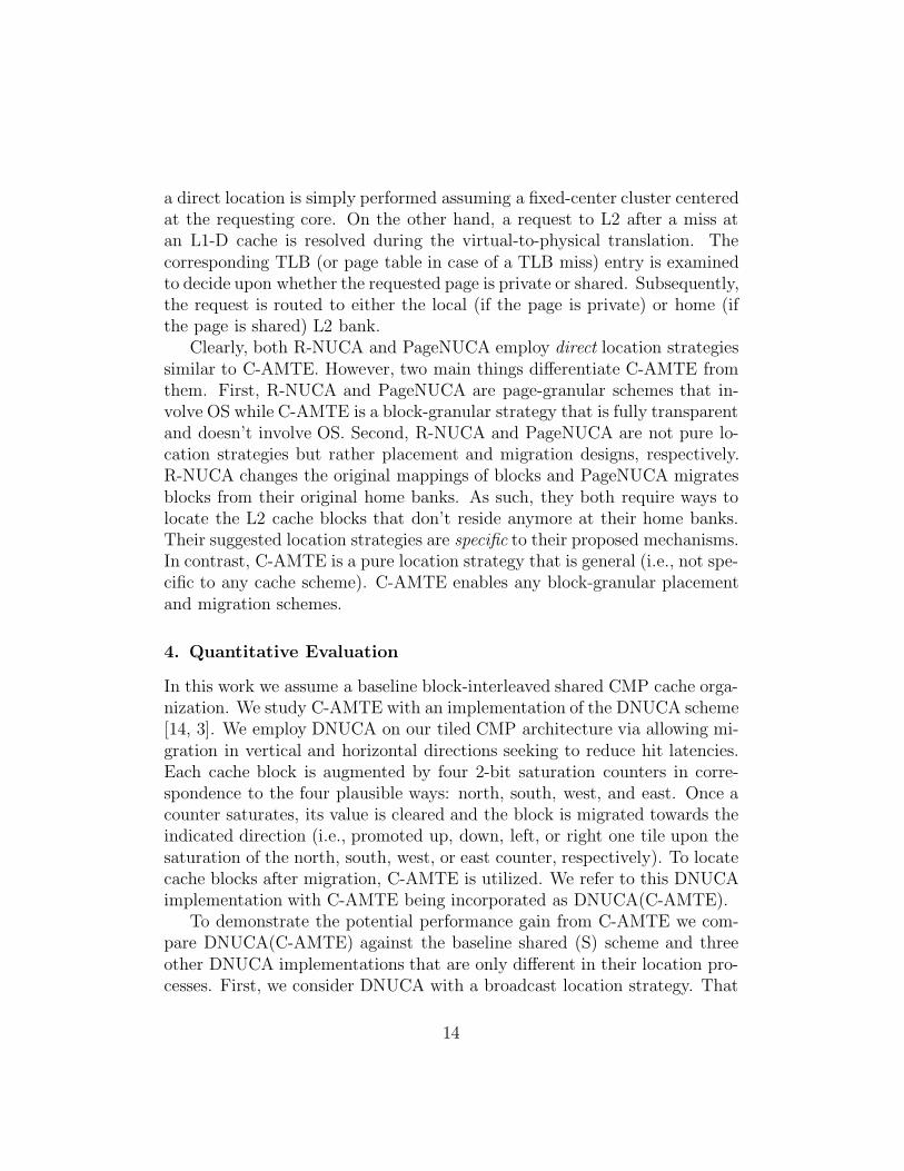
Assuming a 16-tile CMP where each tile encompasses 32KB I/D L1 cachesand a 512KB L2 cache bank and assume PTR and RTR tables each with8K entries per tile, C-AMTE demonstrates a 12% increase of on-chip cachecapacity. To illustrate how the area overhead of C-AMTE scales, Fig. 4 shows
12
the storage requirements of C-AMTE under 16-tile, 32-tile, 64-tile, 128-tile,256-tile, 512-tile, and 1024-tile platforms. The figure shows that C-AMTEwith full-map bit vector (one bit for every core) per each principal trackingentry (C-AMTE(Full)) scales poorly especially after involving more than 64cores on a single chip. Clearly, what makes C-AMTE non-scalable to alarge number of tiles is the bit vector associated with each principal trackingentry. C-AMTE, however, needs not incorporate full-map vectors. Similarto sparse directories [10] and SGI Origin style design [18], C-AMTE caninvolve more compact (coarse) vectors to improve upon the poor scalabilityat a moderate bandwidth increase. For instance, a bit vector can containone bit for every four cores (C-AMTE(Comp4)), or one bit for every eightcores (PDA(Comp8)) and rely on a broadcast or multicast protocol to trackreplicated tracking entries.
3.5. Qualitative Comparison with Closely Related Designs
Two of the closely related location strategies are those proposed and utilizedby PageNUCA [7] and R-NUCA [13]. Chaudhuri [7] suggested PageNUCAwhich employs data migration at page granularity. Access patterns of coresare dynamically monitored and pages are migrated to banks that minimizethe access time for the sharing cores. To locate the migratory pages at theL2 space, each core maintains at the L1 level two tables (organized exactly asTLBs) that map the original physical frame number of an instruction or datapage to the migrated frame number. These tables are referred to as iL1Mapand dL1Map, respectively. Upon each L2 request, the appropriate table islooked up before routing the request to the correct L2 bank. An entry inthe appropriate L1Map is loaded from another unified map table (L2Map)maintained at the L2 level when the corresponding page table entry is loadedin the TLB at the time of a TLB miss. On a migration, the new physicalframe number of a page is sent to the sharing cores (with the help of a sharingvector maintained at a table referred to as PACT) so that they can updatetheir L1Map tables appropriately.
Hardavellas et al. [13] proposed R-NUCA that also relies on OS. R-NUCAclassifies cache accesses to either private, shared, or instructions. Privatepages are placed at the local L2 banks of the requesting cores, shared at fixedaddress-interleaved on-chip locations, and instructions at non-overlappingfixed-center clusters of L2 banks. R-NUCA extends page table and TLBentries to distinguish between private and shared pages. A request to L2after a miss at the L1-I cache is immediately classified as an instruction and
13
a direct location is simply performed assuming a fixed-center cluster centeredat the requesting core. On the other hand, a request to L2 after a miss atan L1-D cache is resolved during the virtual-to-physical translation. Thecorresponding TLB (or page table in case of a TLB miss) entry is examinedto decide upon whether the requested page is private or shared. Subsequently,the request is routed to either the local (if the page is private) or home (ifthe page is shared) L2 bank.
Clearly, both R-NUCA and PageNUCA employ direct location strategiessimilar to C-AMTE. However, two main things differentiate C-AMTE fromthem. First, R-NUCA and PageNUCA are page-granular schemes that in-volve OS while C-AMTE is a block-granular strategy that is fully transparentand doesn’t involve OS. Second, R-NUCA and PageNUCA are not pure lo-cation strategies but rather placement and migration designs, respectively.R-NUCA changes the original mappings of blocks and PageNUCA migratesblocks from their original home banks. As such, they both require ways tolocate the L2 cache blocks that don’t reside anymore at their home banks.Their suggested location strategies are specific to their proposed mechanisms.In contrast, C-AMTE is a pure location strategy that is general (i.e., not spe-cific to any cache scheme). C-AMTE enables any block-granular placementand migration schemes.
4. Quantitative Evaluation
In this work we assume a baseline block-interleaved shared CMP cache orga-nization. We study C-AMTE with an implementation of the DNUCA scheme[14, 3]. We employ DNUCA on our tiled CMP architecture via allowing mi-gration in vertical and horizontal directions seeking to reduce hit latencies.Each cache block is augmented by four 2-bit saturation counters in corre-spondence to the four plausible ways: north, south, west, and east. Once acounter saturates, its value is cleared and the block is migrated towards theindicated direction (i.e., promoted up, down, left, or right one tile upon thesaturation of the north, south, west, or east counter, respectively). To locatecache blocks after migration, C-AMTE is utilized. We refer to this DNUCAimplementation with C-AMTE being incorporated as DNUCA(C-AMTE).
To demonstrate the potential performance gain from C-AMTE we com-pare DNUCA(C-AMTE) against the baseline shared (S) scheme and threeother DNUCA implementations that are only different in their location pro-cesses. First, we consider DNUCA with a broadcast location strategy. That
14
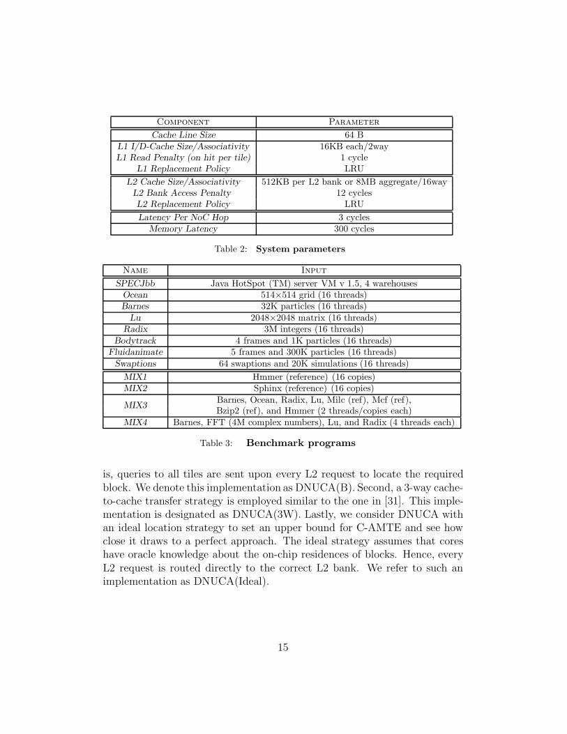
Component Parameter
Cache Line Size 64 B
L1 I/D-Cache Size/Associativity 16KB each/2wayL1 Read Penalty (on hit per tile) 1 cycle
L1 Replacement Policy LRU
L2 Cache Size/Associativity 512KB per L2 bank or 8MB aggregate/16wayL2 Bank Access Penalty 12 cyclesL2 Replacement Policy LRU
Latency Per NoC Hop 3 cyclesMemory Latency 300 cycles
Table 2: System parameters
Name Input
SPECJbb Java HotSpot (TM) server VM v 1.5, 4 warehousesOcean 514×514 grid (16 threads)Barnes 32K particles (16 threads)
Lu 2048×2048 matrix (16 threads)Radix 3M integers (16 threads)
Bodytrack 4 frames and 1K particles (16 threads)Fluidanimate 5 frames and 300K particles (16 threads)
Swaptions 64 swaptions and 20K simulations (16 threads)
MIX1 Hmmer (reference) (16 copies)MIX2 Sphinx (reference) (16 copies)
MIX3Barnes, Ocean, Radix, Lu, Milc (ref), Mcf (ref),Bzip2 (ref), and Hmmer (2 threads/copies each)
MIX4 Barnes, FFT (4M complex numbers), Lu, and Radix (4 threads each)
Table 3: Benchmark programs
is, queries to all tiles are sent upon every L2 request to locate the requiredblock. We denote this implementation as DNUCA(B). Second, a 3-way cache-to-cache transfer strategy is employed similar to the one in [31]. This imple-mentation is designated as DNUCA(3W). Lastly, we consider DNUCA withan ideal location strategy to set an upper bound for C-AMTE and see howclose it draws to a perfect approach. The ideal strategy assumes that coreshave oracle knowledge about the on-chip residences of blocks. Hence, everyL2 request is routed directly to the correct L2 bank. We refer to such animplementation as DNUCA(Ideal).
15
4.1. Methodology
We present our results based on a detailed full system simulation using Vir-tutech’s Simics 3.0.29 [1]. We use our own CMP cache modules fully de-veloped in-house. We implement the XY-routing algorithm and accuratelymodel congestion for all types of messages. A tiled CMP architecture com-prised of 16 UltraSPARC-III Cu processors is simulated running with Solaris10 OS. Each processor uses an in-order core model. The tiles are organizedas a 4×4 grid connected by a 2D mesh network on-chip (NoC). A 3-cyclelatency (in addition to the NoC congestion delay) per hop is incurred whena datum traverses through the mesh network [32, 31]. Each tile encompassesa switch, an aggregate 32KB I/D L1 cache, a 512KB L2 cache bank, and atracking table (TR) with 16K entries. The latency to lookup a TR table ishidden under the delay to enqueue the request in the port scheduler of thelocal switch [7]. Lastly, for coherence enforcement at the L1 cache level, a dis-tributed in-cache MESI-based directory protocol is employed (fully verifiedand tested). Table 2 details our configuration’s experimental parameters.
We use a mixture of multithreaded and multiprogramming workloads tostudy the five designs, S, DNUCA(B), DNUCA(3W), DNUCA(C-AMTE),and DNUCA(Ideal). For multithreaded workloads we use the commercialbenchmark SpecJBB [28], five shared memory programs from the SPLASH-2suite [30] (Ocean, Barnes, Lu, Radix, and FFT), and three applications fromthe PARSEC suite [4] (Bodytrack, Fluidanimate, and Swaptions). We com-posed multiprogramming workloads using the above considered SPLASH-2 benchmarks and five other applications from SPEC2006 [28] (Hmmer,Sphinx, Milc, Mcf, and Bzip2). Table 3 shows the data sets and other im-portant features of the simulated workloads. Lastly, the programs are fastforwarded to get past of their initialization phases. After various warm-upperiods, each SPLASH-2 and PARSEC benchmark is run until the comple-tion of its main loop, and each of SpecJBB, MIX1, MIX2, MIX3, and MIX4is run for 20 billion user instructions.
4.2. Results
Fig. 5 demonstrates the average L2 access latency (AAL) of S, DNUCA(B),DNUCA(3W), DNUCA(C-AMTE), and DNUCA(Ideal) schemes normalizedto S. The incurred latency per L2 access is defined depending on three sce-narios. First, it can involve only the L2 access time. This happens when a hitoccurs to a local L2 bank from a requesting core. Second, it can incorporatedistance latency (computed in terms of the number of hops traversed between
16
!"
!#$"
!#%"
!#&"
!#'"
("
(#$"
(#%"
)*+,-.." /,+01" .021+)" 20345" 67" )89:;<=>" .<?@AB9CD" EFGH?9=HI9AJ" K45(" K45$" K45L" K45%" 0MN#"
0MJB9NJ"6$"0CCJ>>"69AJ=C@"
.J=COI9BD>"
)" 317,0P.Q" 317,0PLRQ" 317,0P,S0KT+Q" 317,0P43+06Q"
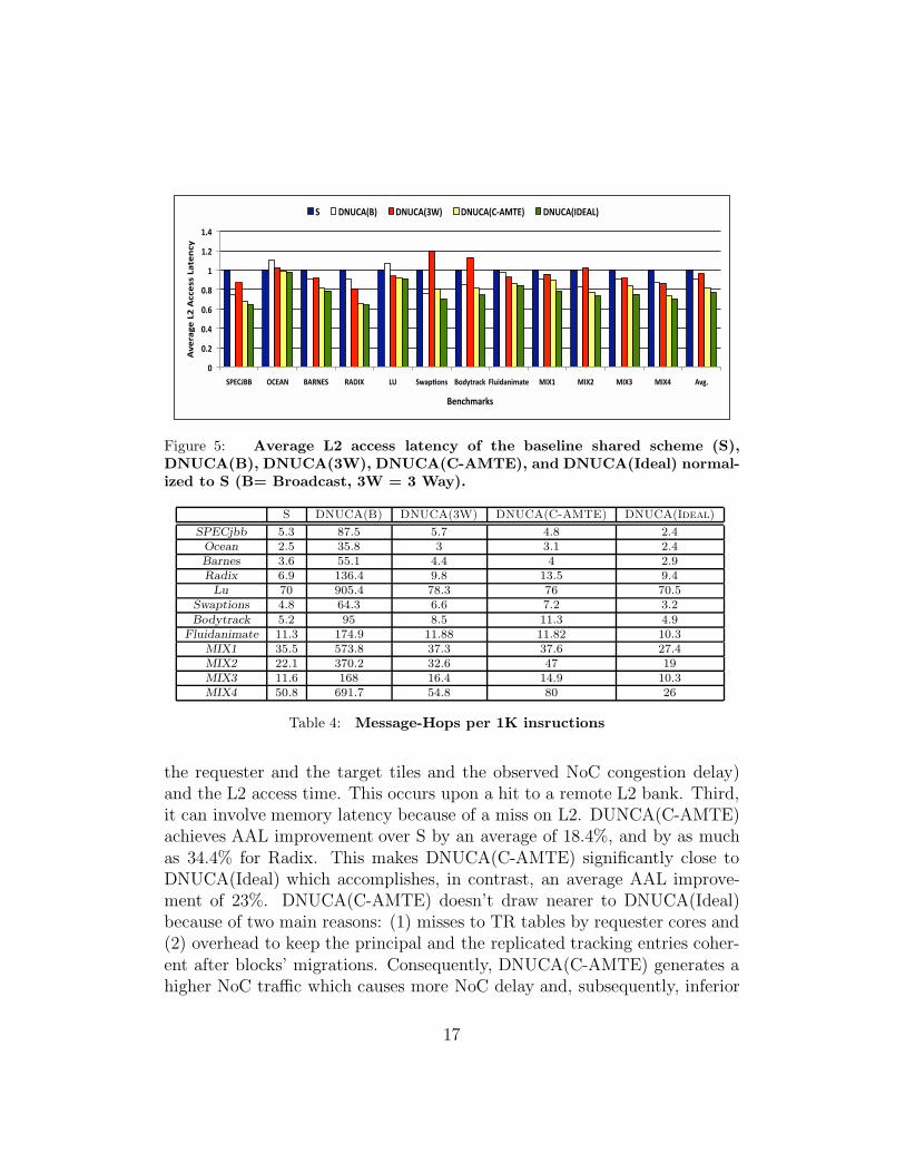
Figure 5: Average L2 access latency of the baseline shared scheme (S),DNUCA(B), DNUCA(3W), DNUCA(C-AMTE), and DNUCA(Ideal) normal-ized to S (B= Broadcast, 3W = 3 Way).
S DNUCA(B) DNUCA(3W) DNUCA(C-AMTE) DNUCA(Ideal)
SPECjbb 5.3 87.5 5.7 4.8 2.4Ocean 2.5 35.8 3 3.1 2.4Barnes 3.6 55.1 4.4 4 2.9Radix 6.9 136.4 9.8 13.5 9.4
Lu 70 905.4 78.3 76 70.5Swaptions 4.8 64.3 6.6 7.2 3.2
Bodytrack 5.2 95 8.5 11.3 4.9Fluidanimate 11.3 174.9 11.88 11.82 10.3
MIX1 35.5 573.8 37.3 37.6 27.4MIX2 22.1 370.2 32.6 47 19MIX3 11.6 168 16.4 14.9 10.3MIX4 50.8 691.7 54.8 80 26
Table 4: Message-Hops per 1K insructions
the requester and the target tiles and the observed NoC congestion delay)and the L2 access time. This occurs upon a hit to a remote L2 bank. Third,it can involve memory latency because of a miss on L2. DUNCA(C-AMTE)achieves AAL improvement over S by an average of 18.4%, and by as muchas 34.4% for Radix. This makes DNUCA(C-AMTE) significantly close toDNUCA(Ideal) which accomplishes, in contrast, an average AAL improve-ment of 23%. DNUCA(C-AMTE) doesn’t draw nearer to DNUCA(Ideal)because of two main reasons: (1) misses to TR tables by requester cores and(2) overhead to keep the principal and the replicated tracking entries coher-ent after blocks’ migrations. Consequently, DNUCA(C-AMTE) generates ahigher NoC traffic which causes more NoC delay and, subsequently, inferior
17
!"
!#$"
!#%"
!#&"
!#'"
("
(#$"
)*+,-.." /,+01" .021+)" 20345" 67" )89:;<=>" .<?@AB9CD" EFGH?9=HI9AJ" K45(" K45$" K45L" K45%" 0MN#"
+OJCG;<="PHI
J"
.J=CQI9BD>"
)" 317,0R.S" 317,0RLTS" 317,0R,U0KP+S" 317,0R4?J9FS"
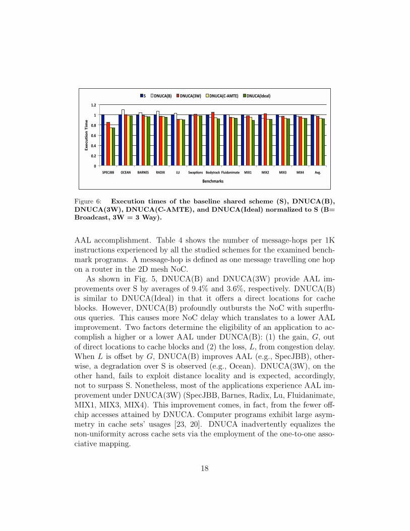
Figure 6: Execution times of the baseline shared scheme (S), DNUCA(B),DNUCA(3W), DNUCA(C-AMTE), and DNUCA(Ideal) normalized to S (B=Broadcast, 3W = 3 Way).
AAL accomplishment. Table 4 shows the number of message-hops per 1Kinstructions experienced by all the studied schemes for the examined bench-mark programs. A message-hop is defined as one message travelling one hopon a router in the 2D mesh NoC.
As shown in Fig. 5, DNUCA(B) and DNUCA(3W) provide AAL im-provements over S by averages of 9.4% and 3.6%, respectively. DNUCA(B)is similar to DNUCA(Ideal) in that it offers a direct locations for cacheblocks. However, DNUCA(B) profoundly outbursts the NoC with superflu-ous queries. This causes more NoC delay which translates to a lower AALimprovement. Two factors determine the eligibility of an application to ac-complish a higher or a lower AAL under DUNCA(B): (1) the gain, G, outof direct locations to cache blocks and (2) the loss, L, from congestion delay.When L is offset by G, DNUCA(B) improves AAL (e.g., SpecJBB), other-wise, a degradation over S is observed (e.g., Ocean). DNUCA(3W), on theother hand, fails to exploit distance locality and is expected, accordingly,not to surpass S. Nonetheless, most of the applications experience AAL im-provement under DNUCA(3W) (SpecJBB, Barnes, Radix, Lu, Fluidanimate,MIX1, MIX3, MIX4). This improvement comes, in fact, from the fewer off-chip accesses attained by DNUCA. Computer programs exhibit large asym-metry in cache sets’ usages [23, 20]. DNUCA inadvertently equalizes thenon-uniformity across cache sets via the employment of the one-to-one asso-ciative mapping.
18
To that end, Fig. 6 presents the execution times of S, DNUCA(B),DNUCA(3W), DNUCA(C-AMTE), and DNUCA(Ideal) normalized to S.Across all benchmarks, DNUCA(B), DNUCA(3W), DNUCA(C-AMTE), andDNUCA(Ideal) outperform S by averages of 1.4%, 2.6%, 6.7%, and 8%, re-spectively. Though DNUCA(B) accomplished 9% and 9.2% AAL reductionsover S for Barnes and Radix respectively, this didn’t effectively translate toan improvement in the overall system performance.
5. Concluding Remarks and Remaining Work
Cache management in CMP is crucial to fuel its performance growth. Thispaper proposes C-AMTE, a mechanism that effectively simplifies the processof locating cache blocks in CMP caching schemes that employ either one-to-one or one-to-many associative mappings. C-AMTE stores tracking entriesthat correspond to cache blocks at per-core data structures for direct loca-tions at subsequent accesses. We demonstrated the effectiveness of C-AMTEby applying it to the DNUCA [3, 14] migration scheme (i.e., a scheme thatadopts one-to-one associative mapping). A performance improvement of upto 25.2% has been achieved, close to that of a perfect location strategy.
Lastly, having established the effectiveness of C-AMTE, optimizations toreduce hardware cost, a sensitivity study to different RT table sizes (or al-ternatively RTR and PTR tables), alternatives on evicting principal trackingentries, protocols on replacing blocks, and applying C-AMTE to more CMPcaching schemes, specifically to schemes that incorporate one-to-many as-sociative mapping (e.g., replication schemes), are among the obvious futuredirections.
References
[1] Virtutech AB. Simics Full System Simulator “http://www.simics.com/”
[2] L. Barroso et al. “Piranha: A Scalable Architecture Based on Single-Chip Multiprocessing,” ISCA,May 2000.
[3] B. M. Beckmann and D. A. Wood. “Managing Wire Delay in Large Chip-Multiprocessor Caches,”MICRO, Dec. 2004.
[4] C. M. Bienia, S. Kumar, J. P. Singh, and K. Li. “The PARSEC Benchmark Suite: Characterizationand Architectural Implications,” PACT, Oct. 2008.
[5] L. Censier and P. Feautrier. “A New Solution to Coherence Problems in Multicache Systems,”IEEE Trans. Comput. C-27 (12): 1112- 1118, Dec. 1978.
[6] J. Chang and G. S. Sohi. “Cooperative Caching for Chip Multiprocessors,” ISCA, June 2006.
[7] M. Chaudhuri. “PageNUCA: Selected Policies for Page-grain Locality Management in Large SharedChip-multiprocessor Caches,” HPCA, pp. 227-238, Feb. 2009.
19
[8] Z. Chishti, M. D. Powell, and T. N. Vijaykumar. “Optimizing Replication, Communication, andCapacity Allocation in CMPs,” ISCA, June 2005.
[9] S. Cho and L. Jin “Managing Distributed Shared L2 Caches through OS-Level Page Allocation,”MICRO, Dec 2006.
[10] A. Gupta, W. D. Weber, and T. Mowry. “Reducing Memory and Traffic Requirements for ScalableDirectory-Based Cache Coherence Schemes,” Int’l Conference on Parallel Processing, August 1990.
[11] Z. Guz, I. Keidar, A. Kolodny, U. C. Weiser. “Utilizing Shared Data in Chip Multiprocessors. withthe Nahalal Architecture,” SPAA, June 2008.
[12] M. Hammoud, S. Cho, and R. Melhem. “ACM: An Efficient Approach for Managing Shared Cachesin Chip Multiprocessors ,” HiPEAC, pp. 319–330, Jan. 2009.
[13] N. Hardavellas, M. Ferdman, B. Falsafi, and A. Ailamaki. “Reactive NUCA: Near-Optimal BlockPlacement and Replication in Distributed Caches,” ISCA, June 2009.
[14] J. Huh, C. Kim, H. Shafi, L. Zhang, D. Burger, and S. W. Keckler. “A NUCA Substrate for FlexibleCMP Cache Sharing,” ICS, June 2005.
[15] M. Kandemir, F. Li, M. J. Irwin, and S. W. Son. “A Novel Migration-Based NUCA Design forChip Multiprocessors,” SC, Nov. 2008.
[16] C. Kim, D. Burger, and S. W. Keckler. “An Adaptive, Non-Uniform Cache Structure for Wire-DelayDominated On-Chip Caches,” ASPLOS, pp. 211–222, Oct. 2002.
[17] P. Kongetira, K. Aingaran, and K. Olukotun. “Niagara: A 32-Way MultithreadedSparc Processor,”IEEE Micro, 25(2): 21–29, March-April 2005.
[18] J. Laudon and D. Lenoski. “The SGI Origin: A ccNUMA Highly Scalable Server,” ISCA, June1997.
[19] M. R. Marty and M. D. Hill. “Virtual Hierarchies to Support Server Consolidation,” ISCA, June2007.
[20] M. K. Qureshi, D. Thompson, and Y. N. Patt. “The V-WAY Cache: Demand-Based Associativityvia Global Replacement,” ISCA, pp. 544–555, June 2005.
[21] N. Rafique, W. Lim, M. Thottethodi. “Architectural Support for Operating System-Driven CMPCache Management ,” PACT, Sep. 2006.
[22] Research at Intel. “Introducing the 45nm Next-Generation Intel CoreTM Microarchitecture,” WhitePaper.
[23] D. Rolan, B. B. Fraguela, and R. Doallo “Adaptive line placement with the set balancing cache,”MICRO, pp. 529–540, Dec. 2009.
[24] A. Ros, M. E. Acacio, and J. M. Garcıa “Scalable Directory Organization for Tiled CMP Architec-tures,” CDES, July 2008.
[25] K. Strandberg. “Which OS? Considerations for Performance-asymmetric, Multi-core Platforms,”Research at Intel, White Paper.
[26] B. Sinharoy, R. N. Kalla, J. M. Tendler, R. J. Eickemeyer, and J. B. Joyner. “POWER5 SystemMicroarchitecture,” IBM J. Res. & Dev., 49(1):–25, July. 2005.
[27] S. Srikantaiah, M. Kandemir, and M. J. Irwin. “Adaptive Set Pinning: Managing Shared Cachesin Chip Multiprocessors,” ASPLOS, pp. 135-144, March 2008.
[28] Standard Performance Evaluation Corporation. http://www.specbench.org.
[29] D. Tam, R. Azimi, L. Soares, and M. Stumm. “Managing Shared L2 Caches on Multicore Systemsin Software,” WIOSCA, 2007.
[30] S. C. Woo, M. Ohara, E. Torrie, J. P. Singh, and A. Gupta. “The SPLASH-2 Programs: Charac-terization and Methodological Considerations,” ISCA, pp. 24–36, July 1995.
[31] M. Zhang and K. Asanovic. “Victim Migration: Dynamically Adapting Between Private and SharedCMP Caches,” TR-2005-064, MIT, Oct. 2005.
[32] M. Zhang and K. Asanovic. “Victim Replication: Maximizing Capacity while Hiding Wire Delayin Tiled Chip Multiprocessors,” ISCA, June 2005.
20

![Improving Cache Performance using Victim Tag Stores · compactly implemented using a Bloom filter [ 3] and a counter. Our mechanism requires no modifications to the cache. In addition,](https://img.pdfslide.us/doc/110x75/5f0c2ab97e708231d4341192/improving-cache-performance-using-victim-tag-stores-compactly-implemented-using.jpg)


![Time/a]Ì^ : 2 hours (H³Oôç) Full Marks - Ajmal Foundationajmalfoundation.org/admin/myfiles/q2009c10.pdf · Time/a ]Ì^: 2 hours ... son of Baba Amte and his wife Mandkini Amte](https://img.pdfslide.us/doc/110x75/5a78dab07f8b9a70238d6a39/timea-2-hours-ho-full-marks-ajmal-found-2-hours-son-of-baba-amte.jpg)


![] Leveraging Vistex for SAP Implementations Makarand Amte March 31, 2011](https://img.pdfslide.us/doc/110x75/5a4d1b7a7f8b9ab0599b8ca2/-leveraging-vistex-for-sap-implementations-makarand-amte-march-31-2011.jpg)