Embed Size (px)
Citation preview

c© 2007 Linh Hoang Vu

INVERTIBILITY AND INPUT-TO-STATE STABILITY OF SWITCHEDSYSTEMS AND APPLICATIONS IN ADAPTIVE CONTROL
BY
LINH HOANG VU
B.Eng., University of New South Wales, 2002M.S., University of Illinois at Urbana-Champaign, 2003
DISSERTATION
Submitted in partial fulfillment of the requirementsfor the degree of Doctor of Philosophy in Electrical and Computer Engineering
in the Graduate College of theUniversity of Illinois at Urbana-Champaign, 2007
Urbana, Illinois
Doctoral Committee:
Associate Professor Daniel Liberzon, ChairProfessor Tamer BasarProfessor Rayadurgam SrikantAssociate Professor Christoforos Hadjicostis

ABSTRACT
This dissertation aims to study basic properties–invertibility and stability–of switched
systems and their applications in control.
We formulate the invertibility problem for switched linear systems, which concerns
finding conditions on a switched system so that one can uniquely recover the switching
signal and the input from an output and an initial state. In solving the invertibility
problem, we introduce the concept of singular pairs and we provide a necessary and
sufficient solution for invertibility of switched linear systems, which says that every
subsystem should be invertible and there is no singular pair. We propose a switching
inversion algorithm for switched systems to find inputs and switching signals that
generates a given output starting at a given initial state.
Another result of the dissertation addresses stability of switched nonlinear systems.
Unlike switched linear systems where there always exists a constant switching gain
among the Lyapunov functions of the subsystems, the existence of such constant gains
is not guaranteed for switched nonlinear systems in general. We provide conditions on
how slow the switching signals should be in order to guarantee input-to-state stability
(or asymptotic stability) of a switched system if all the subsystems are input-to-state
stable (or asymptotically stable, respectively), both when a constant switching gain
exists and when it does not. The slowly switching conditions are characterized via
switching profiles, dwell-time switching, and average dwell-time switching.
As control applications of switched systems, we apply our stability results for
switched systems to the problem of adaptively controlling uncertain nonlinear plants
and linear time-varying plants. For uncertain nonlinear plants with bounded noise
and disturbances, we show that using supervisory control, all the closed-loop signals
can be kept bounded for arbitrary initial conditions when the controllers provide the
ii

ISS property with respect to the estimation errors. We also show that supervisory
control is capable of stabilizing uncertain linear plants with large parameter varia-
tion in the presence of unmodeled dynamics and bounded noise and disturbances,
provided that the unmodeled dynamics are small enough and the parameters vary
slowly enough as described by switching profiles.
iii

To mom, dad, and my other half
iv

ACKNOWLEDGMENTS
I would like to express my deepest gratitude to my adviser, Professor Daniel Liberzon.
I have been very fortunate to have an adviser who completely understands and sup-
ports me throughout my graduate study. Daniel gave me freedom to explore on my
own, and at the same time, guidance and advice when I needed them. Sometimes the
research went slowly, and Daniel’s patience and support helped me overcome crises
and finish the dissertation. I am also grateful to Daniel for holding me to a high
research standard, never compromising thoroughness in favor of a quick publication.
More than just being an academic adviser, Daniel gave me valuable advice in career
and job situations (and also social situations). I am also thankful to Daniel for en-
couraging me to improve my writing and communication skills in English (which is
my second language).
I also thank Professor Tamer Basar, Professor Rayadurgam Srikant, and Professor
Christoforos Hadjicostis for serving on my thesis committee and giving comments
and constructive criticisms on my research and on the dissertation. I especially thank
Professor Hadjicostis who was on sabbatical at the time of the final defense but still
participated via phone conference despite his local time being evening.
I thank my friends and fellows in the Control Group: Debasish Chatterjee, Shreyas
Sundaram, Peter Hokayem, Aneel Tanwani, and Yoav Sharon, for giving me feedback
on my research and sharing research ideas, joy, and fun.
For their various forms of support during my graduate study, I also thank the
following former and current staff in the Control Group : Frances Bridges, Rebecca
Lonberger, Ronda Rigdon, John Bambenek, and Dan Block. I also thank the staff
in the Publications Office in the department of Electrical and Computer Engineering
(ECE) for helping correct typos in the draft of the dissertation.
v

The financial support provided by my adviser through a research assistantship
via grants from the National Science Foundation (NSF) and the Defense Advanced
Research Projects Agency (DARPA) and the financial support provided by the ECE
department through a teaching assistantship are gratefully acknowledged.
Last but not least, I thank my parents for all the love and support they have
provided me through the years, and Thu Pham, my other half, for all her love, care,
understanding, and never-failing support.
vi

TABLE OF CONTENTS
CHAPTER 1 INTRODUCTION . . . . . . . . . . . . . . . . . . . . 1
1.1 Switched Systems . . . . . . . . . . . . . . . . . . . . . . . . . . . . . 11.1.1 Autonomous switched systems . . . . . . . . . . . . . . . . . . 31.1.2 Switched systems with inputs . . . . . . . . . . . . . . . . . . 4
1.2 Examples of Switched Systems . . . . . . . . . . . . . . . . . . . . . . 51.3 Dissertation Contributions . . . . . . . . . . . . . . . . . . . . . . . . 101.4 Notations . . . . . . . . . . . . . . . . . . . . . . . . . . . . . . . . . 13
CHAPTER 2 INVERTIBILITY OF SWITCHED SYSTEMS . . . 18
2.1 Linear Time-Invariant Systems . . . . . . . . . . . . . . . . . . . . . 212.1.1 The structure algorithm and the range theorem . . . . . . . . 23
2.2 Invertibility Problem for Continuous-Time Switched Linear Systems . 292.3 Singular Pairs . . . . . . . . . . . . . . . . . . . . . . . . . . . . . . . 302.4 A Solution of the Invertibility Problem . . . . . . . . . . . . . . . . . 322.5 Output Generation . . . . . . . . . . . . . . . . . . . . . . . . . . . . 402.6 Examples . . . . . . . . . . . . . . . . . . . . . . . . . . . . . . . . . 462.7 Robust Invertibility . . . . . . . . . . . . . . . . . . . . . . . . . . . . 502.8 Discrete-Time Switched Systems . . . . . . . . . . . . . . . . . . . . . 51
2.8.1 Input invertibility . . . . . . . . . . . . . . . . . . . . . . . . . 522.8.2 Invertibility . . . . . . . . . . . . . . . . . . . . . . . . . . . . 57
2.9 Applications . . . . . . . . . . . . . . . . . . . . . . . . . . . . . . . . 622.9.1 Topology recovery in multiagent networked systems . . . . . . 64
CHAPTER 3 STABILITY OF SWITCHED SYSTEMS . . . . . . 69
3.1 Stability Definitions . . . . . . . . . . . . . . . . . . . . . . . . . . . . 693.2 Dwell-Time and Average Dwell-Time Switching . . . . . . . . . . . . 733.3 Input-to-State Properties With Average Dwell-Time Switching . . . . 753.4 Event Profiles . . . . . . . . . . . . . . . . . . . . . . . . . . . . . . . 793.5 Gain Functions . . . . . . . . . . . . . . . . . . . . . . . . . . . . . . 833.6 Class KLS, KLS2, and KLβ Functions . . . . . . . . . . . . . . . . . 853.7 Asymptotic Stability . . . . . . . . . . . . . . . . . . . . . . . . . . . 87
3.7.1 Problem formulation . . . . . . . . . . . . . . . . . . . . . . . 873.7.2 Asymptotic stability of switched systems . . . . . . . . . . . . 893.7.3 Asymptotic stability of impulsive systems . . . . . . . . . . . 943.7.4 Examples . . . . . . . . . . . . . . . . . . . . . . . . . . . . . 96
3.8 Input-to-State Stability . . . . . . . . . . . . . . . . . . . . . . . . . . 973.8.1 Problem formulation . . . . . . . . . . . . . . . . . . . . . . . 973.8.2 Input-to-state property of scalar jumped variables: The general
case . . . . . . . . . . . . . . . . . . . . . . . . . . . . . . . . 99
vii

3.8.3 Input-to-state property of scalar jumped variables: The expo-nentially decaying case . . . . . . . . . . . . . . . . . . . . . . 104
3.8.4 Input-to-state stability of switched systems . . . . . . . . . . . 1093.8.5 Affine profiles . . . . . . . . . . . . . . . . . . . . . . . . . . . 1113.8.6 Asymptotic stability for vanishing disturbances . . . . . . . . 1123.8.7 Input-to-state stability of impulsive systems . . . . . . . . . . 1143.8.8 Examples . . . . . . . . . . . . . . . . . . . . . . . . . . . . . 116
CHAPTER 4 SUPERVISORY CONTROL . . . . . . . . . . . . . . 119
4.1 The Supervisory Control Framework . . . . . . . . . . . . . . . . . . 1194.2 Supervisory Control of Uncertain Nonlinear Plants . . . . . . . . . . 123
4.2.1 Boundedness under weaker hypotheses . . . . . . . . . . . . . 1264.2.2 Example . . . . . . . . . . . . . . . . . . . . . . . . . . . . . . 128
4.3 Supervisory Control of Uncertain Linear Time-Varying Plants . . . . 1324.3.1 Supervisory control design . . . . . . . . . . . . . . . . . . . . 1354.3.2 Design parameters . . . . . . . . . . . . . . . . . . . . . . . . 1364.3.3 The closed-loop structure . . . . . . . . . . . . . . . . . . . . 1374.3.4 Interconnected switched systems . . . . . . . . . . . . . . . . . 1414.3.5 Interconnected switched systems with unmodeled dynamics . . 1514.3.6 Stability of the closed-loop control system . . . . . . . . . . . 1584.3.7 Example . . . . . . . . . . . . . . . . . . . . . . . . . . . . . . 161
4.4 Model Reference Supervisory Adaptive Control . . . . . . . . . . . . 1624.4.1 Model reference controller for a known LTI plant . . . . . . . 1634.4.2 Supervisory adaptive tracking . . . . . . . . . . . . . . . . . . 1654.4.3 Example . . . . . . . . . . . . . . . . . . . . . . . . . . . . . . 169
CHAPTER 5 CONCLUSIONS AND FUTURE WORK . . . . . . 171
REFERENCES . . . . . . . . . . . . . . . . . . . . . . . . . . . . . . . . 174
AUTHOR’S BIOGRAPHY . . . . . . . . . . . . . . . . . . . . . . . . 180
viii

CHAPTER 1
INTRODUCTION
1.1 Switched Systems
Many complex systems exhibit switching behaviors. These switching behaviors may
come from physical changes in the systems, such as an aircraft during different thrust
modes [1], a walking robot during leg impact and leg swing modes [2], or different
formations of a group of vehicles [3]. Switching behaviors can also arise as results of
control design, such as in gain scheduling control [4] or supervisory adaptive control
[5]. In numerous situations, dynamical systems with switching behaviors can be
described by switched systems. Formally, a switched system comprises:
1. A family of dynamical subsystems parameterized over an index set P. Denote
the family of the subsystems by Γp, p ∈ P, where Γp is the system with index
p. The subsystem dynamics are described by ordinary differential equations as
for nonswitched systems.
2. A switching signal σ : D → P that indicates the active subsystem at every time
instant, where D ⊆ [0,∞) is a time domain of the switched system. Switching
signals are piecewise right-continuous functions that take constant values in be-
tween every two consecutive discontinuities. The discontinuities of σ are called
switching times or switches. We assume that there is a finite number of switches
in every finite time interval. The phenomenon of infinitely many switches in
a finite interval is called Zeno behavior (see, for example, [6]). We explicitly
rule out Zeno behavior as it may cause finite escape time even if all the subsys-
tems are forward complete (i.e., solutions are defined over [0,∞) for all initial
states). Zeno behavior also translates to hardware components moving at very
high frequency and thus is not desirable in practice.
1

The following are standard assumptions on switched systems:
1. We assume that all the subsystems live in the same state space, which is also the
state space of the switched system. While it is theoretically feasible to obtain
more general results in the case the state spaces of the individual subsystems
are different, virtually all of the switched systems encountered in practice have
subsystems of the same state dimension. We will remark on the case of the
subsystems having different state spaces when it is applicable.
2. We assume that there are no state jumps at switching times unless it is clearly
stated otherwise. It is possible to extend the results in this thesis to include
the case of state jumps at switching times such that if τ is a switching time,
x(τ) = mσ(τ),σ(τ−)(x(τ−)) where mp,q : Rn → Rn, p, q ∈ P is a reset map for
the switched system’s state when the active subsystem changes from subsystem
with index p to subsystem with index q (here Rn denotes the state space of the
switched system). We will remark on more general cases of nonidentity reset
maps when it is applicable.
Remark 1.1 The switched system model described in this dissertation places empha-
sis on the sequence of active modes over the time and neglects the actual switching
mechanism (which may depend on the states as well as the inputs of the subsystems).
While we may lose certain detail, the sequence of active modes over the time is often
sufficient to draw conclusions about system properties (such as asymptotic stability
or input-to-state stability) of the switch system (see Chapter 3). However, it is noted
that in certain situations, more information about the switching signal (such as the
switching mechanism) may become useful [7].
2

1.1.1 Autonomous switched systems
For autonomous switched systems, the subsystem dynamics do not depend on external
signals. The subsystems can be written as
Γp :
x = fp(x),
y = hp(x),p ∈ P, (1.1)
where x ∈ Rn, y ∈ Rr, fp are locally Lipschitz, and hp are continuous for all p ∈ P.
The switched system with the subsystems (1.1) is written as
Γσ :
x = fσ(x),
y = hσ(x).(1.2)
For every switching signal σ, fσ(x) is piecewise right-continuous in t and locally
Lipschitz in x. Therefore, for every initial state x(t0) = x0, the nonlinear equation
x = fσ(x) has a unique solution over some interval [t0, Tmax) (see, for example, [8,
Theorem 3.1]). In particular, the solution can be written as
x(t) = x0 +
∫ t
t0
fσ(τ)(x(τ))dτ. (1.3)
The function (1.3) satisfies the differential equation x = fσ(x) everywhere except at
switching times. At a switching time τ , limt→τ+dxdt
= fσ(τ)(x(τ)) and limt→τ−dxdt
=
limt→τ− fσ(τ−)(x(τ)). In essence, solutions of (1.2) can be viewed as concatenations
of solutions of the active subsystems along the time. If every subsystem is forward
complete, then the switched system is also forward complete (i.e., solutions are defined
on [0,∞)) in view of the fact that switching signals do not have Zeno behavior.
3

1.1.2 Switched systems with inputs
For switched systems with inputs, the subsystems can be written as
Γp :
x = fp(x, u),
y = hp(x, u),p ∈ P, (1.4)
where x ∈ Rn, u ∈ Rℓ, y ∈ Rr, fp are locally Lipschitz, and hp are continuous for all
p ∈ P. The switched system with the subsystems (1.4) is then written as
Γσ :
x = fσ(x, u),
y = hσ(x, u).(1.5)
While inputs in (1.4) are functions, inputs in (1.5) are actually not functions in the
usual sense: an input u of the switched system (1.5) is a concatenation of the input
segments of the active subsystems, and these segments can have different dimensions.
To describe inputs and outputs of switched systems in general, we need to use the
concept of hybrid functions and compatible switching signals and inputs.
Definition 1.1 A function f : D → Rm1 , . . . ,Rmk is a (piecewise right-continuous)
hybrid function if
(i) for all t ∈ D, the function value f(t) ∈ Rmi for some i, 1 6 i 6 k, and lims↑t f(s)
and lims↓t f(s) exist;
(ii) f has a finite number of discontinuities in every finite interval, where t is a
discontinuity of f if lims↑t f(s) 6= lims↓t f(s);
(iii) f is continuous in between every two consecutive discontinuities and f is right
continuous at discontinuities, i.e., f(t) = lims↓t f(s).
Denote by Hpc,m1,...,mk the set of piecewise right-continuous hybrid functions on
Rm1 , . . . ,Rmk (the order ofm1, . . . , mk is irrelevant). When the dimensionsm1, . . . , mk
are not important, we will write Hpc instead.
4

Definition 1.2 Consider the switched system (1.5) where the input dimensions of
the subsystems are mp, p ∈ P. A hybrid function u is compatible with a switching
signal σ if the domains of σ and u are the same, and further, dim(u(t)) = mσ(t) for
all t in the domain.
The concept of hybrid functions and compatible switching signals and input func-
tions allows us to describe solutions of the switched system (1.5) rigorously. For the
switched system (1.5), denote by mP the set of input dimensions. Denote by Hpc,mP
the corresponding set of hybrid functions. This set Hpc,mP is the set of all admissible
inputs of the switched system. For every initial state x0, a switching signal σ, and a
compatible hybrid function u ∈ Hpc,mP , a solution of (1.5) exists and is unique, which
follows from the existence and uniqueness of solutions for each individual subsystem.
The solution can be written as
x(t) = x0 +
∫ t
t0
fσ(s)(x(s), u(s))ds. (1.6)
Equation (1.6) satisfies the differential equation x = fσ(x, u) everywhere except at
switching times. If τ is a switching time, then limt→τ+dxdt
= fσ(τ)(x(τ), u(τ)) and
limt→τ−dxdt
= limt→τ− fσ(τ−)(x(τ), u(τ−)). Similarly to autonomous switched systems,
solutions of switched systems with inputs can be viewed as concatenations of solutions
of the active subsystems along the time.
1.2 Examples of Switched Systems
We provide here some representative examples of switched systems encountered in
practice. The first two examples are switched systems resulting from controller design
even though the plants are nonswitched in nature. The last three examples are
examples of plants which are switched in nature.
5

1. Gain scheduling
Gain scheduling is a common control technique used in practice to handle plants’
nonlinearity (see, e.g., the survey paper [4]). Suppose that one wants to stabi-
lize or regulate a nonlinear plant x = f(x, u), y = h(x). One obtains a lin-
ear parameter-varying (LPV) model for the plant, either by rewriting nonlinear
terms as time-varying parameters (quasi-LPV method) or by linearizing the
plant around a family of operating points xp, p ∈ P (linearization scheduling
method). For each linear plant x = Apx+Bpu, y = Cpx with a fixed parameter
p ∈ P, one designs a linear controller Cp : xc = ApxC + Bpx, up = CpxC + Dpx
that meets the control objective. One constructs a variable θ (which is called
scheduling variable) that can be measured directly, and devises a map M :
Range(θ)→ P that maps behavior of θ to specific controllers. Then the closed-
loop control system can be approximated by the switched system xCL = AσxCL,
where xCL = (x, xC), Ap =
Ap +BpDp BpCp
Bp Ap
, and σ(t) := M(θ(t)) is the
switching signal that returns the index of the active controller at every time
based on the value of θ.
2. Switching supervisory control
Switching supervisory control (see, e.g., [9, Chapter 6] and the references therein;
we will also cover supervisory control in detail in Chapter 4) is an adaptive con-
trol scheme that employs switching among multiple controllers (in contrast to
other continuously tuning adaptive schemes). Consider a parameterized un-
certain plant x = f(p∗, x, u), y = h(p∗, x) where p∗ is the unknown constant
parameter. The range Ω of p∗ is partitioned into a finite number of subsets
Ωi, i ∈ P such that⋃
i∈P Ωi = Ω, where P is the index set. For each sub-
set Ωi, one selects a nominal value pi ∈ Ωi. One then designs a family of
controllers, one for each plant with p = pi, i ∈ P. One also designs a su-
pervisor which produces a switching signal σ : [0,∞) → P that indicates the
6

active controller at every time. Denote xp = f(p, xp, y), up = h(p, xp, y) the
dynamics of the controller with index p. It follows that the closed-loop con-
trol system is the switched system xCL = gσ(xCL), where xCL = (x, xσ) and
gp(xCL) =
f(p∗, x, h(p, xp, x))
f(p, xp, x)
, p ∈ P.
3. Aircraft during different flying modes
Aircraft that have multiple flying modes can be modeled as switched systems [10].
In conventional take-off and landing (CTOL), an aircraft moves in parallel to the
horizonal axis while in vertical take-off and landing (VTOL), an aircraft moves
up or down without significant change in the horizonal position (such as the
McDonnell Douglas YAV-8B Harrier). Some aircraft can operate in both CTOL
and VTOL modes, and changing between modes can be done via a transition
mode (TRANSITION). Each mode can be described by an ordinary differential
equation. Below is the example taken from [10] that describes the dynamics of
an aircraft in CTOL, VTOL, and TRANSITION modes, respectively:
Γ1 : M
x
z
= R(θ)
RT (α)
−D
L
+
T
−ǫu
−
0
Mg
,
Γ2 : M
x
z
= R(θ)
0
T − ǫu
−
0
Mg
,
Γ3 : M
x
z
= R(θ)
RT (α)
−D
L
+
T cos δ
T sin δ − ǫu
−
0
Mg
,
where x, z are coordinate variables, L is the lift, D is the drag, M is the mass, θ
is the pitch angle, α is the angle of attack, R(θ) and R(α) are rotation matrices, δ
is the nozzle angle, ǫ, g are constants, and T and u are control inputs. Switching
between TRANSITION and CTOL modes occurs when (δ, δ) = (0, 0) and switch-
ing between TRANSITION and VTOL modes occurs when (δ, δ) = (π/2, 0). The
7

switched system that describes the aircraft dynamics in this context is Γσ where
σ : [0,∞)→ 1, 2, 3 is a switching signal that indicates the mode the aircraft is
in at every instant of time. In [10], the authors used switched systems to analyze
trajectory tracking of an aircraft through different flight modes.
4. Multiagent systems
Switched systems can arise from switching among different topologies of a net-
work of agents [3, 11, 12]. A topology of a multiagent network is a graph G
whose nodes represent agents and edges between nodes denote communications
between the corresponding agents. For a node i, denote by Ni the set of neigh-
bors of node i where neighbors of a node i are all other nodes that have an edge
with node i. Denote by xi = fi(xi, ui) the dynamics of agent i where xi is the
state and ui is the control input. In cooperative multiagent systems, the agents’s
control law can use not only its own state but also information from neighbor-
ing agents and the control law is of the form ui = gi(xi, xj , j ∈ Ni). The
collective dynamics of the network of agents are obtained by putting together
all the agent dynamics and take the form x = FG(x), where x = (x1, . . . , xn)
and FG is a function depending on the structure of the graph G. For exam-
ple (see [3]), with the agent dynamics xi = ui and the cooperative control law
ui =∑
j∈Ni(xj − xi) (known as consensus protocol), the collective network dy-
namics are x = −L(G)x, where L(G) = [lij ], lij =
−1 if j ∈ Ni, j 6= i,
|Ni| i = j
is
the graph Laplacian of G.
Switching comes into the picture if we allow the topology G to vary over time,
G : [0,∞) → Gp, p ∈ P. We then have a network with switching topology.
Networks with switching topology can be modeled as switched systems where the
subsystems are the network dynamics with fixed topologies and the switching
signal, in this case, indicates the active topology at every time. In particular,
8
the switched system describing multiagent networks with switching topology is
x = Fσ(x), where x = Fp(x) is the collective dynamics of the network with
topology Gp, p ∈ P, and σ(t) := p : G(t) = Gp.
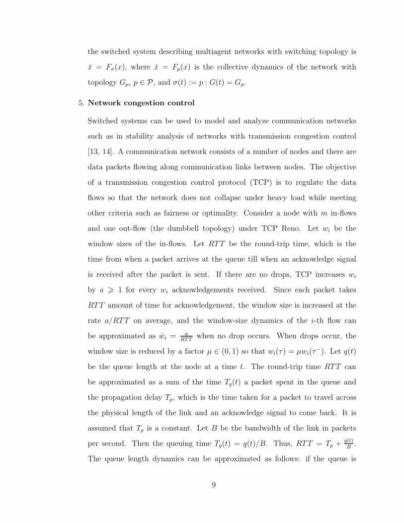
5. Network congestion control
Switched systems can be used to model and analyze communication networks
such as in stability analysis of networks with transmission congestion control
[13, 14]. A communication network consists of a number of nodes and there are
data packets flowing along communication links between nodes. The objective
of a transmission congestion control protocol (TCP) is to regulate the data
flows so that the network does not collapse under heavy load while meeting
other criteria such as fairness or optimality. Consider a node with m in-flows
and one out-flow (the dumbbell topology) under TCP Reno. Let wi be the
window sizes of the in-flows. Let RTT be the round-trip time, which is the
time from when a packet arrives at the queue till when an acknowledge signal
is received after the packet is sent. If there are no drops, TCP increases wi
by a > 1 for every wi acknowledgements received. Since each packet takes
RTT amount of time for acknowledgement, the window size is increased at the
rate a/RTT on average, and the window-size dynamics of the i-th flow can
be approximated as wi = aRTT
when no drop occurs. When drops occur, the
window size is reduced by a factor µ ∈ (0, 1) so that wi(τ) = µwi(τ−). Let q(t)
be the queue length at the node at a time t. The round-trip time RTT can
be approximated as a sum of the time Tq(t) a packet spent in the queue and
the propagation delay Tp, which is the time taken for a packet to travel across
the physical length of the link and an acknowledge signal to come back. It is
assumed that Tp is a constant. Let B be the bandwidth of the link in packets
per second. Then the queuing time Tq(t) = q(t)/B. Thus, RTT = Tp + q(t)B
.
The queue length dynamics can be approximated as follows: if the queue is
9

not full, there are∑
i wi
RTTincoming packets per second and there are B outgoing
packets per second; if the queue is full and there still are incoming packets,
then incoming packets will be dropped and the window sizes are reduced. We
then have q =
0 if q = 0,∑
i wi
RTT< B or q = qmax,
∑i wi
RTT> B
∑i wi
RTT− B else,
, where
the first case deals with the fact that the queue length can neither be negative
nor exceed the maximal length qmax.
A network with TCP Reno can be approximated by a switched system Γσ whose
subsystems Γ1 and Γ2 are the dynamics of the network when the queue is not
full and when the queue is full, respectively:
Γ1 :
wi = aBBTp+q
,
q = B∑
i wi
BTp+q− B,
Γ2 :
wi = aBBTp+q
,
q = 0,.
The switching signal is σ : [0,∞) → 1, 2. Switching from mode 1 to mode 2
occurs when the queue becomes full, i.e., q > qmax and∑
i wi
BTp+q> 1. Switching
from mode 2 to mode 1 occurs after RTT amount of time from the time a
switch from mode 1 to mode 2 happens. In this example, the reset map m1,2 is
the identity map but m2,1(wi) = µwi.
1.3 Dissertation Contributions
The contributions of the thesis can be categorized into three main areas:
1. We formulate the invertibility problem for switched systems (Section 2.2), which
is a new problem that has not been considered before. The invertibility problem
can be seen as an extension of the classic invertibility problem for nonswitched
systems [15, 16, 17] to switched systems as well as an extension of the mode
detection problem for autonomous switched systems [18, 19] to switched systems
with unknown inputs.
10

We provide a necessary and sufficient condition for a switched linear system to
be invertible (Section 2.4). In solving the invertibility problem, we introduce the
new concept of singular pairs for switched systems with inputs. This concept
can be seen as an extension of the concept of indistinguishable pairs for switched
systems without inputs in [18] to systems with unknown inputs. We provide a
necessary and sufficient algebraic criterion for checking singular pairs. Using the
singular pair concept, we find that a switched system is invertible over some
input set if and only if all the subsystems are invertible and there is no singular
pair over the output set.
We also consider the output generation problem for switched systems, which
concerns finding inputs and switching signals that can generate a given output
from a given initial state even if the switched system is not invertible (Section
2.5). We provide a switching inversion algorithm that produces all inputs and
switching signals capable of generating a given function in a finite time interval
from a given initial state, when there are finitely many such inputs and switching
signals. In the algorithm, the concept of singular pair plays a crucial role as it
allows us to identify potential switching times even though the output may be
smooth at these times.
2. The dissertation provides new stability results for switched nonlinear systems
as well as a new way to characterize the slow switching property of switching
signals.
Previously, switching signals have been characterized using the dwell-time and
average dwell-time like concepts [20, 21, 22]. To describe more general classes
of switching signals, we propose the use of event profiles – functions that can
be nonlinear in general to describe the relationship between the numbers of
switches in time intervals and the interval lengths – to characterize switching
signals (Section 3.4). Dwell-time and average dwell-time switching become the
11

special cases where the event profiles are uniform and affine.
Unlike the case of switched linear systems where there always exists a constant
switching gain among the Lyapunov functions of the subsystems, the existence
of such a constant is not guaranteed for switched nonlinear systems in general.
Using event profiles, we characterize classes of switching signals which guarantee
asymptotic stability of autonomous switched nonlinear systems with globally
asymptotically stable subsystems without requiring the existence of a constant
switching gain. This result significantly extends a previous result in [21] that uses
average dwell-time as well as assuming the existence of a constant switching gain.
For switched nonlinear systems with inputs, we study the input-to-state stability
(ISS) property. We provide conditions on the switching signals to guarantee ISS
of switched systems when all the subsystems are ISS, both when a constant
switching gain among the ISS-Lyapunov functions of the subsystems exists and
when it does not.
Event profiles can also be used to describe properties of sequences of time in-
stants, of which the switching times of a switching signal are one example. As
such, event profiles can also be used to characterize impulse times of impul-
sive systems. Using event profiles, we also obtain stability results for impulsive
systems.
3. The dissertation advances adaptive control by showing how switched supervisory
control can be used to stabilize uncertain nonlinear systems with disturbances
and to stabilize uncertain linear time-varying systems.
Previously, it was only known that switching supervisory control could stabilize
an uncertain nonlinear plant provided that switching stops in finite time with
the assumption that there are no disturbances [23, 24]. In the presence of dis-
turbances, switching is not guaranteed to stop. The contribution of the thesis is
to show that even if switching does not stop in finite time, it is still possible to
12

achieve boundedness of all the closed-loop continuous signals under some mild
assumptions on controller design. This result is built upon our ISS result for
switched nonlinear systems in Section 3.3.
We also show how supervisory control can be used to control uncertain linear sys-
tems with large time-varying unknown parameters. This result directly extends
reported results on supervisory control of uncertain linear plants with a constant
unknown parameter [20, 21, 25, 26]. Unlike the case with constant parameters,
closed-loop analysis leads to stability analysis of interconnected switched sys-
tems, in which two switched systems are interacting with each other via a non-
trivial way other than input-output connections. Using the ISS result in Section
3.8, we show that even if the unknown parameter is changing over time, the
supervisory control scheme still guarantees boundedness of all the closed-loop
states in the presence of noises and disturbances, provided that the parameter
varies slowly enough as described by certain event profiles.
1.4 Notations
Functions
Denote by K the class of continuous functions [0,∞) → [0,∞) which are zero at
zero and increasing. Denote by K∞ the subclass of K functions that are unbounded.
Denote by L the class of continuous functions [0,∞)→ [0,∞) which are decreasing
and converge to 0 as their argument tends to∞. Denote by KL the class of functions
[0,∞)2 → [0,∞) which are class K in the first argument and class L in the second
argument.
Denote by CnD the set of n times differentiable functions on a domain D ⊆ R; when
the domain is not relevant, we write Cn. Denote by FpcD the set of piecewise right-
continuous functions on a domain D ⊆ R. By piecewise right-continuous functions,
13

we mean that there is a finite number of jump discontinuities in any finite interval;
there are no hole discontinuities and vertical asymptotes; the function is continuous in
between every two consecutive discontinuities; and the function is continuous from the
right at discontinuities. To avoid excessive rigidness, we will use the term “piecewise
continuous” throughout the paper, and it is understood that “piecewise continuous”
means “piecewise right-continuous.” When the domain is not important, we write
Fpc. Denote by Fn the subset of Fpc whose elements are n times differentiable
between every two consecutive discontinuities. For a function u : D → Rn, denote by
uQ the restriction of u onto a subset Q of D. Denote by 0 the zero elements; whether
0 being the zero scalar, zero vectors or zero functions is clear from the context.
Operators
Denote by (·)t0,t, t > t0 > 0, the segmentation operator such that for a function f ,
(f)t0,t(τ) :=
f(τ) τ ∈ [t0, t)
0 else.
(1.7)
The segmentation operator is a generalization of the truncation operator where t0 = 0.
For a vector v, denote by | · | the Euclidean norm |v| := (vTv)12 . Denote by ‖(·)‖∞
the L∞ norm ‖x‖∞ := supt∈[0,∞) |x(t)|. We say that x ∈ L∞ if ‖x‖∞ exists and we
say x ∈ L∞e if ‖(x)0,t‖∞ exists for all t < ∞. Define the exponentially weighted L2
norm as
‖(x)t0,t‖2,λ :=
(∫ t
t0
e−λ(t−τ)|x(τ)|2dτ) 1
2
t > t0. (1.8)
Denote by ‖(x)t0,∗‖2,λ the function of t obtained when we let t be a variable in (1.8).
We refer to ‖ · ‖2,λ as the L2,λ norm (the 2 refers to the 2-norm of x and λ refers to
the exponentially decaying rate) and we say that x ∈ L2,λ if ‖(x)t0,t‖2,λ exists for all
t > t0. These norms are popular in functional analysis of input/output properties
of systems (see, e.g., [27, Chapter 3] or [8, Chapter 5]). It is often assumed that
14

t0 = 0 and hence, truncation is used, but nonzero initial time is important in our
analysis and this prompts the use of the segmentation operator. The L2,λ norm has
the following properties:
1. Addition and multiplication:
‖α(f)t0,t‖2,λ = α‖(f)t0,t‖2,λ ∀f ∈ L2,λ, α > 0. (1.9)
2. Finite gain for L∞e signals:
‖(f)t0,t‖2,λ 6‖(f)t0,t‖∞√
λ∀f ∈ L∞e. (1.10)
3. Reducing the rate of exponentially decaying functions:
‖(e−λ/2)t0,t‖2,λ 61√λ− λ
(e−λ/2)t0,t, ∀λ ∈ (0, λ). (1.11)
4. Composition of norms:
‖(‖(f)t0,∗‖2,λ)t0,t‖2,λ 61√λ− λ
‖(f)t0,t‖2,λ ∀f ∈ L2,λ, 0 < λ < λ > 0, t > τ > t0.
(1.12)
5. Chain rule:
‖(f)t0,t‖22,λ = ‖(f)t0,τ‖22,λe−λ(t−τ) + ‖(f)τ,t‖22,λ ∀t > τ > t0. (1.13)
6. Strictly decreasing in λ:
‖(f)t0,t‖2,λ+δ < ‖(f)t0,t‖2,λ ∀f ∈ L2,λ, δ > 0. (1.14)
Properties 1, 2, 5, and 6 can be verified directly from the definitions of L2,λ norm and
elementary calculus. Following are proofs of Properties (1.11) and (1.12).
15

Proof Proofs of (1.11) and (1.12). We have
‖(e−λ/2)t0,t‖22,2λ =
∫ t
t0
e−λ(t−τ)e−λτdτ = e−λt
∫ t
t0
e(λ−λ)τdτ = e−λt e(λ−λ)t − e(λ−λ)t0
λ− λ ,
=1
λ− λ(e−λt+(λ−λ)t0 − e−λt) 61
λ− λe−λt+λt0 =
1
λ− λe−λ(t−t0).
‖(‖(f)t0,∗‖2,λ)t0,t‖22,λ =
∫ t
t0
e−λ(t−s)
∫ s
t0
e−λ(s−τ)|f(τ)|2dτds
= e−λt
∫ t
t0
e(λ−λ)s
∫ s
t0
eλτ |f(τ)|2dτds
= e−λt 1
λ− λ
∫ t
t0
(∫ s
t0
eλτ |f(τ)|2dτ)de(λ−λ)s
= e−λt 1
λ− λ
(e(λ−λ)s
∫ s
t0
eλτ |f(τ)|2dτ −∫ t
t0
e(λ−λ)seλs|f(s)|2ds)
6 e−λt 1
λ− λ
∫ t
t0
e(λ−λ)seλs|f(s)|2ds
= e−λt 1
λ− λ
∫ t
t0
eλs|f(s)|2ds =:1
λ− λ‖(f)t0,t‖22,λ.
We define the concatenation of two functions as follows: let fi∈Fpc[ti,τi)
, i = 1, 2 (τi
could be ∞); define the concatenation map ⊕ : Fpc×Fpc→Fpc as
(f1 ⊕ f2)(t) :=
f1(t), if t ∈ [t1, τ1),
f2(t2+t−τ1), if t ∈ [τ1, τ1+τ2−t2).
Basically, f1 ⊕ f2 means putting the two functions together in that order. Note that
f1 ⊕ f2 = f1 ∀f2 if τ1 = ∞, and in general, f1 ⊕ f2 6= f2 ⊕ f1. The concatenation of
vector functions is defined as pairwise concatenation of the corresponding elements
(concatenations of functions of different dimensions are defined exactly the same with
the exception that the resulting functions are hybrid functions instead of functions).
The concatenation of an element f and a set S is f ⊕ S := f ⊕ g, g ∈ S. By
16

convention, f ⊕∅ = ∅ ∀f . Finally, the concatenation of two sets S and T is S⊕T :=
f ⊕ g, f ∈ S, g ∈ T; by convention, S ⊕ ∅ = ∅ and ∅ ⊕ S = ∅ ∀S.
Systems
For a linear system Γ, for an initial state x0 and an input u ∈ Fpc, denote by Γx0(u)
the trajectory of the system and by ΓOx0
(u) the corresponding output (the trajectory
exists (in the sense of Caratheodory) and is unique for every initial condition x0 and
input u ∈ Fpc). The initial time, which might be nonzero, is specified by the starting
time t0 in u as t0 = inft ∈ D where D is the domain of u.
For a switched system, denote by S the set of all admissible switching signals.
Denote by σp the constant switching signal such that σp(t) = p ∀t > 0. For a switched
system Γσ, for an initial state x0, a switching signal σ, and a compatible piecewise-
continuous hybrid function u, denote by Γx0,σ(u) the trajectory of the switched system
and by ΓOx0,σ(u) the corresponding output. For the subsystem with an index p ∈ P,
for an initial state x0 and an input u ∈ Fpc, denote by Γp,x0(u) the trajectory of the
subsystem and by ΓOp,x0
(u) the corresponding output.
17

CHAPTER 2
INVERTIBILITY OF SWITCHED SYSTEMS
In this chapter, we address the invertibility problem for switched systems, which
concerns the following question: What is the condition on the subsystems of a switched
system so that, given an initial state x0 and the corresponding output y generated with
some switching signal σ and input u, we can recover the switching signal σ and the
input u uniquely? The aforementioned problem is in the same vein with the classic
invertibility problem for nonswitched linear systems, where one wishes to recover the
input uniquely knowing the initial state and the output. The invertibility problem
for nonswitched linear systems has been studied extensively, first by Brockett and
Mesarovic [15], then with other algebraic criteria and the inversion constructions by
Silverman and Payne [16, 28] and Sain and Massey [17], and also, a geometric criterion
is given by Morse and Wonham [29] (see also the discussions and the references in [30]).
However, the invertibility problem for switched systems has not been investigated and
it is a research topic of this thesis. As in the classic setting, we start with an output
and an initial state, but here, the underlying process constitutes multiple models and
we have an extra ingredient to recover apart from the input, namely, the switching
signal.
On the one hand, switched systems can be seen as generalizations of nonswitched
linear systems (when the switching signal is constant, there is no switching and we
recover nonswitched linear systems). In this regard, the invertibility problem for
switched systems is an extension of the nonswitched counterpart in the sense that we
have to recover the switching signal in addition to the input, based on the output and
the initial state. On the other hand, switched systems can be viewed as higher-level
abstractions of hybrid systems. Recovering the switching signal for switched systems
is equivalent to mode (or discrete state) identification for hybrid systems. For au-
18

tonomous hybrid systems, this mode identification task is a part of the observability
problem for hybrid systems, which has been formulated and solved by Vidal et al.
[18, 19]. Mode detection for nonautonomous hybrid systems using known inputs and
outputs has been studied, for example, in [31, 32] (see also [33]). Here, the difference
is that we do not know the input and we wish to do both mode detection and input
recovery at the same time using the outputs of switched systems. To the best of our
knowledge, the invertibility problem for switched systems is a new problem formu-
lation that can be seen as a nontrivial extension of the classic invertibility problem
to switched systems as well as an extension of the mode identification problem for
hybrid systems to the case with unknown inputs.
Our approach to the invertibility problem is similar in spirit to the approach used
in the switching observability problem by Vidal et al. [18, 19]. In the observabil-
ity problem, the objective is to recover the switching signal and the state uniquely
from the output of a switched system without inputs. The basic idea is to do mode
identification by utilizing relationships among the outputs and the states of the indi-
vidual subsystems (more details are in Section 2.5). For nonswitched systems without
inputs, there is a straightforward relationship between the output and the state in-
volving the observability matrix, which was used to solve the switching observability
problem in [19]. For nonswitched systems with inputs, the relationship among the
output, the input, and the state is much more complicated and is realized using the
structure algorithm [16], with the help of which our results for switched systems are
subsequently developed.
A motivating example
Before going into detail in the next section, we present a motivating example to
illustrate an interesting aspect of the invertibility problem for switched systems that
does not have a counterpart in nonswitched systems (for more details, see Example
19

2.2 in Section 2.6). Consider a switched system consisting of the two subsystems
Γ1 :
x=
1 0
0 −1
x+
1
1
u,
y =[0 1
]x,
, Γ2 :
x=
1 0
−1 2
x+
−1
1
u,
y =[1 2
]x.
Both Γ1 and Γ2 are invertible, which means that for every output y in the output space
of Γ1 and every initial state x0, there exists a unique input u such that the system Γ1
with the initial state x0 and the input u generates the output y, and similarly for Γ2.
(Procedures for checking invertibility of nonswitched linear systems are well-known as
discussed previously; for more details on the invertibility of these Γ1,Γ2, see Example
2.2 in Section 2.6.) Suppose that one is given the following output:
y(t) =
2e2t − 3et, if t ∈ [0, t∗),
c1et + c2e
2t, if t ∈ [t∗, T ),
where t∗ = ln 3, T = 6/5, c1 = 15 + 18 ln(2/3), c2 = −4/3− 4 ln(2/3), and the initial
state x0 = (−1, 0)T , and is asked to reconstruct the switching signal σ and the input
u. Because the output has a discontinuity at time t = t∗ and is smooth everywhere
else, one can guess that t∗ must be a switching time and is the only one (assuming
that there is no state jump at switching times and hence, x is always continuous).
Following this reasoning, since there are two subsystems, there are only two possible
switching signals:
σ1(t) =
1, t ∈ [0, t∗),
2, t ∈ [t∗, T ),
σ2(t) =
2, t ∈ [0, t∗),
1, t ∈ [t∗, T ).
For a fixed switching signal, the active subsystem is known at every instant of time,
and so by invertibility of Γ1 and Γ2, given the output and the initial state, the input
can be reconstructed uniquely. One can then try both the switching signals σ1 and σ2
20

above to see which one gives an input that generates the output y. As it turns out,
none of the switching signals σ1 and σ2 would give an input that generates y. One
might falsely conclude that there are no input and switching signals for the switched
system to generate the given y with the initial state x0. Nonetheless, the output is
generated, uniquely in this case, by the following switching signal and input:
σ(t)=
2, t ∈ [0, t1),
1, t ∈ [t1, t∗),
2, t ∈ [t∗, T ),
u(t)=
0, t ∈ [0, t1),
6e2t−6et, t ∈ [t1, t∗),
0, t ∈ [t∗, T ),
where t1 = ln 2 (details are in Example 2.2 in Section 2.6). In Section 2.5, we will
show how a switch at a later time t = t∗ can be used to recover a switch at an earlier
time t = t1 even if the output is smooth at t = t1.
2.1 Linear Time-Invariant Systems
We provide some background and literature review on the invertibility of linear time-
invariant systems. Consider a linear time-invariant system
Γ :
x = Ax+ Bu,
y = Cx+Du.(2.1)
The invertibility problem for linear systems (more precisely, the left invertibility prop-
erty; from here onward, when we say invertibility we mean left invertibility) concerns
with finding conditions for a linear time-invariant (LTI) system so that for a given
initial state x0, the input-output map Hx0 : U → Y is one-to-one (injective), where U
is the input function space and Y is the corresponding output function space. There
are two major approaches to the problem: one is the algebraic approach where con-
ditions are obtained in terms of matrix rank equalities; the other is the geometric
21

approach that is based on the invariant properties of subspaces.
The algebraic approach relies on the observation that differentiating the output
y reveals extra information about the input u via the term Cx = CAx + CBu. If
one keeps differentiating the output, one obtains more information about the input
u from y, y, y, . . . . It turns out that one needs at most n differentiations, where n is
the state dimension, in order to conclude whether u can be recovered uniquely or not
and thus to establish invertibility of the system. Taking this approach, most well-
known results are the rank condition for invertibility by Sain and Massey [17] and
the structure algorithm by Silverman [16], where the latter differs from the former in
that it only differentiates parts of the output as needed and not the entire output.
The geometric approach is quite different from the algebraic one in that it does
not involve output differentiations. Instead, the invertibility property is realized from
the fact that (i) Hx0 is invertible if and only if the kernel of H0 is trivial, and (ii) the
kernel of H0 is the same as the set of inputs that yield the set V of states that are
reachable from the origin while keeping the output zero. The set V can be calculated
geometrically (in terms of its basis) using the concepts of invariant subspaces and
controllability subspaces (see, e.g., [34] for references on geometric control). Left
invertibility is equivalent to V ∩ B kerD = 0 and Ker B ∩Ker D = 0 (see, e.g.,
[35, Ch. 8.5]; see also [29, 36]).
Remark 2.1 The map Hx0 for nonswitched linear systems enjoys the following prop-
erty thanks to linearity. For nonswitched linear systems, the following are equivalent:
i. There is a unique u such that y = Hx0(u) for one particular pair (x0, y) where y
has a domain D ⊆ [0,∞).
ii. There is a unique u such that y = Hx0(u) for every y in the range of Γx0 for all
possible domains and for all x0 ∈ Rn.
Thus, for nonswitched linear systems, there is no distinction between unique input
recovery for one output and unique input recovery for an output set. Also, the time
22

domain is irrelevant. As a consequence, the output set Y can be taken as the set of
all output functions that are generated by continuous inputs on one arbitrary time
domain or on all possible time domains. As we will see later in Section 2.3, the map
Hx0 for switched systems (as defined in Section 2.2) does not have this property and
a careful consideration of the output set Y is needed. ⊳
2.1.1 The structure algorithm and the range theorem
We will pursue the algebraic approach (a geometric approach is equally interesting
and could be the topic for future research). In particular, we will employ the structure
algorithm for nonswitched linear systems by Silverman [16]. In this section, we cover
the structure algorithm for nonswitched linear systems, closely following [16] and [28].
The reader is referred to [28] for further technical details and proofs.
Consider the linear system (2.1). Let n be the state dimension, m the input
dimension, and ℓ the output dimension. For the moment, assume that the input
u is continuous (for piecewise continuous inputs, see Remark 2.4 below). Let q0 =
rank(D). There exists a nonsingular ℓ× ℓ matrix S0 such that D0 := S0D =
D0
0
,
where D0 has q0 rows and rank q0. Let y0 = S0y and C0 = S0C. Thus, we have
y0 = C0x+D0u. Suppose that at step k, we have yk = Ckx+Dku, where Dk has the
form
Dk
0
; Dk has qk rows and is full rank. Let the partition of Ck be
Ck
Ck
, where
Ck is the first qk rows, and the partition of yk be
yk
yk
, where yk is the first qk rows. If
qk < ℓ, let Mk be the differential operator Mk :=
Iqk0
0 Iℓ−qk(d/dt)
. Then Mkyk =
Ck
CkA
x +
Dk
CkB
u. Let qk+1 = rank
Dk
CkB
. There exists a nonsingular ℓ ×
23

ℓ matrix Sk+1 such that Dk+1 := Sk+1
Dk
CkB
=
Dk+1
0
, where Dk+1 has qk+1
rows and rank qk+1. Let yk+1 := Sk+1Mkyk, Ck+1 := Sk+1
Ck
CkA
. Then yk+1 =
Ck+1x+Dk+1u and we can repeat the procedure. Let Nk :=∏k
i=0 Sk−iMk−i−1, k =
0, 1, . . . (M−1 := I), Nk :=[Iqk
0qk×(ℓ−qk)
]Nk, and Nk :=
[0(ℓ−qk)×qk
Iℓ−qk
]Nk.
Then yk = Nky, yk = Nky, and yk = Nky. Notice that since Dk has ℓ rows and m
columns, qk 6 minℓ,m for all k and since qk+1 > qk, using the Cayley-Hamilton
theorem, it was shown in [28] that there exists a smallest integer α 6 n such that
qk = qα ∀k > α.
If qα = m, the system is invertible (left-invertible) and an inverse is
Γ−1 :
yα = Nαy,
z = (A− BD−1
α Cα)z +BD−1
α yα,
u = −D−1
α Cαz +D−1
α yα
(2.2)
with the initial state z(0) = x0. If qα < m, the system is not invertible, and then a
generalized inverse is
Γ−1 :
yα = Nαy,
z = (A− BD†
αCα)z +BD†
αyα +BKv,
u = −D†
αCαz +D†
αyα +Kv
(2.3)
with the initial state z(0) = x0, where K is a matrix whose columns form a basis
for the null space of Dα and D†
α := DT
α(DαDT
α)−1 is a right-inverse of Dα.1 The
system Γ−1 in (2.3) is called a generalized inverse because y = ΓOx0
(u) if and only if
u = Γ−1,Ox0
(yα, v) for some v.
1(DαDTα )−1 exists because the rows of Dα are linearly independent.
24

From the structure algorithm, it can be seen that yk = Ckx ∀k and hence,
N0
...
Nk
y =
y0
...
yk
=
C0
...
Ck
x =: Lkx ∀k. (2.4)
Using the Cayley-Hamilton theorem, Silverman and Payne have shown in [28] that
there exists a smallest number β, α 6 β 6 n, such that rank(Lk) = rank(Lβ) ∀k > β.
There also exists a number δ, β 6 δ 6 n such that Cδ =∑δ−1
i=0 Pi
(∏δj=i+1 Rj
)Ci for
some matrices Rj from the structure algorithm and some constant matrices Pi (see [28,
p.205] for details). The number δ is not easily determined as α and β. The significance
of β and δ is that they can be used to characterize the set of all outputs of a linear
system as in the range theorem [28, Theorem 4.3]. We include the range theorem
from [28] below. Define the differential operators M1 :=(
dδ
dtδ−∑δ−1
i=0 Pidi
dti
)∏αj=0 Rj
and M2 :=∑δ
j=0
(∏αℓ=j+1Rℓ
)Kj
dδ−1
dtδ−j −∑δ−1
j=0Pj×∑j
k=0
(∏αℓ=k+1Rℓ
)Kk
dj−k
dtj−k for some
matrices Ki from the structure algorithm (see [28] for more details). The notation |tmeans “evaluating at t.”
Theorem 2.1 [28] A function f : [t0, T )→ Rℓ is in the range of Γx0 if and only if
i. f is such that Nδf is defined and continuous;
ii. Nkf |t0 = Ckx0, k = 0, . . . , β − 1;
iii. (M1 −M2Nα)f ≡ 0.
To simplify the presentation of our paper, we paraphrase the range theorem into the
following lemma that is easier to understand at the expense of having to define extra
notations. Define
• N :=
N0
. . .
Nβ−1
, L := Lβ−1, and
25

• Y the set of functions f : D → Rℓ for all D ⊆ [0,∞) which satisfy (i) and
(iii) of Theorem 2.1. The set Y is the set of all outputs of the system Γ that
are generated by all possible continuous inputs and initial states for all possible
durations.
Lemma 2.1 For a linear system Γ, using the structure algorithm on the system ma-
trices, construct a set Y of functions, a differential operator N : Y → C0, and a matrix
L. There exists u ∈ C0 such that y = Γx0(u) if and only if y ∈ Y and Ny|t+0 = Lx0
where t0 is the initial time of y.
Remark 2.2 A special case is qα = ℓ, in which case M1 = M2 = 0 and the condition
(iii) becomes trivial. Also, in this case, α = β = δ. The set Y is simplified to the set of
functions f for which Nδf is defined and continuous. In particular, any Cn function
will be in Y. For an invertible system, qα = ℓ if the input and output dimensions are
the same. ⊳
Remark 2.3 Note from the structure algorithm that regardless of what the input is,
the output and the state are related by the equation Ny|t = Lx(t) for all t > t0, not
just at the initial time t0. The relationship between y and x for systems with inputs is
much more complicated than that for systems without inputs. For the linear system
without input x = Ax, y = Cx, the output is always smooth and the output and the
state are related via the observability matrix OA,C =[CT (CA)T . . . (CAn−1)T
]T
such that (y, y, . . . , y(n−1))T = OA,Cx. For systems with inputs, the output, in general,
is not smooth and the output and the state are related via the equation Ny = Lx for
some differential operator N. For further discussion, see [28, p.204]). ⊳
We found that Lemma 2.1 is better suited for our purpose in the paper than the
more detailed Theorem 2.1. The exact formulae of N, L, and Y are less important
in the understanding of the development for checking singularity in Section 2.3 than
the facts that N is some differential operator, L is some matrix, and Y is some set of
26

functions (when the actual formulae are needed, it is then referred to Theorem 2.1).
What is important is the necessary and sufficient condition asserted by Lemma 2.1.
Roughly speaking, the set Y characterizes continuous functions that can be generated
by the system from all initial positions (the components of the output must be related
in some way via the system matrices A,B,C,D; in some sense, the operators M1 and
M2 capture the coupling among the output components as one input component may
affect several output components). The condition Ny|t+0 = Lx0 guarantees that the
particular y can be generated starting from the particular initial state x0 at time t0.
We evaluate Ny at t+0 , which means limt→t+0Ny|t, to reflect that y does not need
to be defined for t < t0. This is especially useful later when we consider switched
systems where inputs and outputs can be piecewise right-continuous.
Remark 2.4 If we allow piecewise continuous inputs, the invertibility condition for
Γ is still the same (qα = m). The inverse (2.2) and the generalized inverse (2.3) are
still the same but v in (2.3) can be piecewise continuous functions. The inverse, the
generalized inverse, and Theorem 2.1 are applicable in between every two consecutive
discontinuities of the input (on every output segment y[t,τ) in which Nδy[t,τ) exists and
is continuous). ⊳
The differential operator N is used in Lemma 2.1 to deal with a general output y
that may not be differentiable but Ny exists (an example is that y is not differentiable
so y does not exist, but Ny = ddt
(y− y) exists and is continuous). As it will be useful
in our results for switched systems later, let us take a closer look at N. We have
M0y0 =
y0
˙y0
= M0S0y =
S0
0
y +
d
dt
0
S0
y
=: K0,0y +d
dtK0,1y. (2.5)
27

In general, let
Miyi = Ki,0y +d
dt(Ki,1y +. . .+
d
dt(Ki,iy+
d
dtKi,i+1y)). (2.6)
Then in view of Mi+1yi+1 =
Si+1
0
Miyi + d
dt
0
Si+1
Miyi, we have the ℓ× ℓ matrices
Ki,j defined recursively as follows:
Ki+1,j =
Si+1
0
Ki,j +
0
Si+1
Ki,j−1,
0 6 j 6 i+ 2, i > 0, (2.7)
where Ki,−1 = 0 ∀i by convention and K0,0, K0,1 are as in (2.5). Using the notation
in (2.6), in view of Nky = SkMi−1yi−1, then
Ny =: N0y +d
dt(N1y + · · ·+ d
dt(Nβ−2y +
d
dtNβ−1y)), (2.8)
where Ni :=
S0K−1,i
S1K0,i
...
Sβ−1Kβ−2,i
, 0 6 i 6 β − 1, K−1,0 = I and Kj,k = 0 ∀k > j + 2, ∀j by
convention. We then have the following lemma.
Lemma 2.2 Consider the linear system (2.1). Let β be the number and N be the
differential operator as described in the structure algorithm. For any κ > β, for every
y such that Ny exists and is continuous, we have Ny = N0y+ ddt
(N1+· · ·+ ddt
(Nκ−2y+
ddtNκ−1y)), where Ni, 0 6 i 6 β − 1, are as in (2.8) and Ni = 0, i > β.
Note that in general, Ny is calculated by a chain of differentiations and additions
as in the lemma. However, whenever y ∈ Cβ−1, calculating Ny can be simplified to
the matrix multiplication [N0 . . . Nβ−1] by (y, . . . , y(β−1))T .
28

2.2 Invertibility Problem for Continuous-Time Switched
Linear Systems
Consider a switched linear system
Γσ :
x = Aσx+Bσu,
y = Cσx+Dσu,(2.9)
where σ : [0,∞) → P is the switching signal that indicates the active subsystem at
every time, P is some index set in a real vector space, and Ap, Bp, Cp, Dp, p ∈ P, are
the matrices of the individual subsystems. For the sake of presentation, we assume
that the output dimensions of all the subsystems are the same, because detecting
switchings between two subsystems with different output dimensions is trivial. How-
ever, it is emphasized that it is just a technicality to restate our results presented
here to cover the general case where output dimensions are different. The input
dimensions of the subsystems can be different.
For the switched system (2.9), denote by n the state dimension, ℓ the output
dimension, and mp, p ∈ P the input dimensions of the subsystems. Denote by Hx0 :
S×U → Y the (switching signal × input)-output map for some input set U , switching
signal set S, and the corresponding output set Y . We will seek conditions on the
subsystem dynamics so that the map Hx0 is one-to-one for some sets S,U , and Y
(precise problem formulation is in Section 2.2). We do not yet specify here what the
sets U , S, and Y are as we will see in Section 2.3 that injectivity of the map Hx0
depends on particular sets Y and we cannot simply take Y to be the set of all possible
outputs generated by all possible combinations of inputs and switching signals (cf.
Remark 2.1 for nonswitched systems in Section 2.1 below).
The invertibility problem. Consider a (switching signal × input)-output map
Hx0 : S × U → Y for the switched system (2.9). Find a largest possible set Y and a
condition on the subsystems, independent of x0, such that the map Hx0 is one-to-one.
29

2.3 Singular Pairs
We discuss the invertibility of the map Hx0 : S × U → Y for the switched system
(2.9) in more detail. We say that Hx0 is invertible at y if Hx0(σ1, u1) = Hx0(σ2, u2) =
y ⇒ σ1 = σ2, u1 = u2 (similarly for nonswitched systems, Hx0 : U → Y is invertible
at y if Hx0(u1) = Hx0(u2) = y ⇒ u1 = u2). We say that Hx0 is invertible on Y if it
is invertible at y for all y ∈ Y . We say that the switched system is invertible on Y if
Hx0 is invertible on Y for all x0.
There is a major difference between the maps Hx0 for nonswitched systems and
for switched systems. The former is a linear map on vector spaces (i.e., the input
functions). The latter is a nonlinear map on the domain S × U , of which S is not
a vector space. The map Hx0 for nonswitched systems has the property that if Hx0
is invertible at y for one particular pair (x0, y), then the map Hx0 is invertible on
the set of all possible outputs generated by continuous inputs (see Remark 2.1).
In contrast, for switched systems, uniqueness of (σ, u) for one pair (x0, y) does not
imply uniqueness for other pairs, and thus, a switched system may be invertible
on one output set Y1 but not invertible on another set Y2 (which is not the case
for nonswitched systems). This situation prompts a more delicate definition of the
output set Y for switched systems, instead of letting Y be the set generated by all
possible combinations of piecewise continuous inputs and switching signals. For the
invertibility problem, we look for the largest possible set Y and a condition on the
subsystems so that unique recovery of (σ, u) is guaranteed for all y ∈ Y and all
x0 ∈ Rn.
One special case is x0 = 0, y ≡ 0. It is obvious that with u ≡ 0 and any switching
signal, we always have y ≡ 0; i.e., H0(σ, u) = 0 ∀σ regardless of the subsystem
dynamics and therefore the map H0 is not one-to-one if the function 0 ∈ Y . Note
that the available information is the same for both nonswitched systems and switched
systems, namely, the pair (x0, y), but the domain in the switched system case has been
30

enlarged to S × U , compared to U in the nonswitched system case. For nonswitched
systems, under a certain condition on the system dynamics (i.e., when the system
is invertible), the information (x0, y) = (0, 0) is sufficient to determine u uniquely,
while for switched systems that information is insufficient to determine (σ, u) uniquely,
regardless of what the subsystems are. This illustrates why we cannot take the output
set Y to be all the possible outputs. We call those pairs (x0, y) for which Hx0 is not
invertible at y singular pairs. Fortunately, x0 = 0 and y[0,ε) ≡ 0 for some ε > 0 are
the only type of singular pairs that are independent of the subsystems and for other
pairs (x0, y), the invertibility of Hx0 at y depends on the subsystem dynamics and
properties of y.
Definition 2.1 Let x0 ∈ Rn and y ∈ C0 be a function in Rℓ on some time interval.
The pair (x0, y) is a singular pair of the two subsystems Γp,Γq if there exist u1, u2
such that ΓOp,x0
(u1) = ΓOq,x0
(u2) = y.
Essentially, if a state and an output function (the time domain can be arbitrary)
form a singular pair, then there exist inputs for the two systems to produce that same
output starting from that same initial state. We proceed to develop a formula for
checking if (x0, y) is a singular pair of Γp,Γq, utilizing the range theorem by Silverman
and Payne (Theorem 2.1 in this paper). We will use our notations in Lemma 2.1. For
the subsystem indexed by p, denote by Np, Lp, and Yp the corresponding objects of
interest as in Lemma 2.1. It follows from Definition 2.1 and Lemma 2.1 that (x0, y)
is a singular pair if and only if y ∈ Yp ∩ Yq and
Np
Nq
y∣∣t+0
=
Lp
Lq
x0, (2.10)
where t0 is the initial time of y. For a given (x0, y), the condition (2.10) can be
directly verified since all Yp, Yq,Np,Nq, Lp, Lq are known. Observe that 0 ∈ Im
Lp
Lq
31

and we can always have (2.10) with x0 = 0 and y such that
Np
Nq
y|t+0 = 0. In
particular, if y[t0,t0+ε) ≡ 0 and x0 = 0, then (2.10) holds regardless of Np,Nq, Lp, Lq.
Apart from this case, in general,
Np
Nq
y∣∣t+0
= 0 depends on Np,Nq, and y, and it is
possible to find conditions on Np,Nq, Lp, Lq, and y so that there is no x0 satisfying
(2.10) if
Np
Nq
y
∣∣t+06= 0 .
Remark 2.5 The singular pair notion captures the situation where it is not possible
to distinguish between two dynamical systems just using the output and the initial
state. This property leads to the scenario where there is a switch in the underlying
dynamical system yet the output is still smooth at the switching time (as in the moti-
vating example in the introduction). A similar scenario but with a different objective
can be found in the context of bumpless switching [37], in which the objective is to
design the subsystems so that the output of the switched system is continuous. In the
invertibility problem considered here, the subsystems are fixed and the objective is to
recover the switching signal and the input.
2.4 A Solution of the Invertibility Problem
We now return to the invertibility problem. Let Yall be the set of outputs of the
system (2.9) generated by all possible piecewise continuous inputs and switching
signals from all possible initial states for all possible durations (the set Yall can be
seen as all the possible concatenations of all elements of Yp, ∀p ∈ P). Let Y ⊂ Yall
be the largest subset of Yall such that if y ∈ Y and y[t0,t0+ε) ∈ Yp ∩ Yq for some
p 6= q, p, q ∈ P, ε > 0, t0 > 0, then
Np
Nq
y
∣∣t+06= 0. Literally speaking, we avoid
functions whose segments can form singular pairs with x0 = 0 (so that even if x0 = 0,
there is no y ∈ Y that can form a singular pair with x0). Excluding such functions
32

from our output set, we can impose conditions on the subsystems to eliminate the
possibility of singular pairs for all x0 ∈ Rn and all y ∈ Y. Note that the singular pair
concept in Definition 2.1 is defined for continuous functions. Applying to switched
systems, we check for singular pairs for the continuous output segments in between
consecutive discontinuities at the output (note that Yp ∩ Yq ⊆ C0 if the intersection
is non-empty). We have the following result.
Theorem 2.2 Consider the switched system (2.9) and the output set Y. The switched
system is invertible on Y if and only if all the subsystems are invertible and the
subsystem dynamics are such that for all x0 ∈ Rn and y ∈ Y ∩ C0, the pairs (x0, y)
are not singular pairs of Γp,Γq for all p 6= q, p, q ∈ P.
Proof Sufficiency: Suppose that all the subsystems are invertible and the subsys-
tem dynamics are such that for all x0 ∈ Rn and y ∈ Y ∩C0, the pairs (x0, y) are not
singular pairs of Γp,Γq for all p 6= q, p, q ∈ P.
Suppose that Hx0(σ1, u1) = Hx0(σ2, u2) = y ∈ Y .
Let t1 := mint > 0 : u1 or u2 or σ1 or σ2 is discontinuous at t. Let p = σ1(0)
and q = σ2(0). From Lemma 2.1, we have Npy|0+ = Lpx0 and Nqy|0+ = Lqx0, and
y[0,t1) ∈ Yp ∩ Yq. By definition, (x0, y[0,t1)) is a singular pair of Γp,Γq if p 6= q. Also
by definition, y[0,t1) ∈ Y ∩C0. Since there is no singular pair for Γp,Γq, we must have
p = q, i.e., σ1(t) = σ2(t) = p ∀t ∈ [0, t1). Since Γp is invertible, u1[0,t1) = u2[0,t1) =
u[0,t1) = Γ−1,Op,x0
(y[0,t1)) is uniquely recovered on [0, t1) (recall from Section 1.4 that
Γ−1,Op,x0
(y[0,t1)) is the output of the inverse of Γp starting at x0 with input y[0,t1)). Let
x1 = x(t−1 ). By continuity of the trajectory, we have x(t1) = x(t−1 ) = x1. If t1 = ∞,
we then have σ1(t) = σ2(t) and u1(t) = u2(t) ∀t ∈ [0,∞).
Suppose that t1 < ∞. We have Hx1(σ1[t1,∞), u1[t1,∞)) = Hx1(σ2[t1,∞), u2[t1,∞)) =
y[t1,∞). Let t2 := mint > t1 : u1 or u2 or σ1 or σ2 is discontinuous at t. Repeating
the arguments in the previous paragraph, we must have σ1(t) = σ2(t) = q ∀t ∈ [t1, t2)
for some q ∈ P, and u1[t1,t2) = u2[t1,t2) = u[t1,t2) = Γ−1,Oq,x0
(y[t1,t2)) is uniquely recovered
33

on [t1, t2).
If t2 =∞, we then have σ1(t) = σ2(t) and u1(t) = u2(t) for all t ∈ [0,∞); otherwise,
repeat the procedure with y[t2,∞). Since there cannot be infinitely many discontinuities
in a finite interval (in other words, if there are infinitely many discontinuities, the
interval must be [0,∞)), we conclude that σ1(t) = σ2(t) and u1(t) = u2(t) ∀t ∈ [0,∞).
Necessity: Suppose that Γp is not invertible for some p ∈ P. Pick some x0 and
y ∈ Y ∩ Yp ; this is always possible from the definition of the set Y . Since y ∈ Yp,
there exists u such that y = Γp,x0(u). Since Γp is not invertible, there exists u 6= u such
that Γp,x0(u) = y (see Remark 2.1). Then Hx0(σp, u) = Hx0(σ
p, u) = y. That means
the map Hx0 is not invertible at y and thus, the switched system is not invertible on
Y , a contradiction. Therefore, Γp must be invertible for all p ∈ P.
Suppose that there are some x0 ∈ Rn, y ∈ Y ∩ C0 and p 6= q, p, q ∈ P such that
(x0, y) is a singular pair of Γp,Γq. This means ∃u1, u2 ∈ C0 (not necessarily different)
such that Γp,x0(u1) = Γq,x0(u2) = y and therefore, Hx0(σp, u1) = Hx0(σ
q, u2) = y.
Since σp 6= σq, the foregoing equality implies that Hx0 is not invertible at y, and thus,
the switched system is not invertible on Y , a contradiction. Therefore, for all x0 ∈ Rn
and y ∈ Y ∩ C0, (x0, y) are not singular pairs of Γp,Γq for all p 6= q, p, q ∈ P.
Theorem 2.2 provides a necessary and sufficient condition for a switched system
to be invertible on the set Y . While checking for singularity for given x0 and y is
feasible using the property (2.10), in general, checking for singularity for all x0 and
all y ∈ Y (and hence, checking invertibility) is not an easy task. We now develop a
rank condition for checking invertibility of switched systems, which is more compu-
tationally friendly. In the case when the subsystem input and output dimensions are
equal, the rank condition is also necessary. We first have the following lemma. For
an index p, let Wp := [Np,0 Np,1 . . . Np,n−1] where Np,0, . . . , Np,n−1 are the matrices
as in Lemma 2.2 for the subsystem with index p.
Lemma 2.3 Consider the switched system (2.9) and the output set Y. Consider the
34

following two statements:
S1. The subsystem dynamics are such that for all x0 ∈ Rn and y ∈ Y ∩C0, the pairs
(x0, y) are not singular pairs of Γp,Γq for all p 6= q, p, q ∈ P.
S2. The subsystem dynamics are such that
Rank
Wp Lp
Wq Lq
= Rank
Wp
Wq
+ Rank
Lp
Lq
(2.11)
for all p 6= q, p, q ∈ P such that Yp ∩ Yq 6= 0.
Then S2 always implies S1. If the subsystems are invertible and the input and output
dimensions are the same, then S1 also implies S2.
Proof S2 ⇒ S1:
Suppose that there exist x0 and y ∈ Y ∩ C0 such that (x0, y) is a singular pair of
Γp,Γq for some p 6= q. Then we have the equality (2.10). From Lemma 2.2, we have
Np
Nq
y =
Np,0
Nq,0
y +
d
dt
Np,1
Nq,1
y + · · ·+ d
dt
Np,n−2
Nq,n−2
y +
d
dt
Np,n−1
Nq,n−1
y
(2.12)
in view of the definition of Np,i, Nq,i, 0 6 i 6 n−1. Since
Np,n−1
Nq,n−1
y is in the range of
Np,n−1
Nq,n−1
, we must also have d
dt
Np,n−1
Nq,n−1
y ∈ Range
Np,n−1
Nq,n−1
. Then
Np,n−2
Nq,n−2
y +
ddt
Np,n−1
Nq,n−1
y is in the range of
Np,n−2 Np,n−1
Nq,n−2 Nq,n−1
. Continuing this procedure, we
conclude that
Np
Nq
y ∈ Range
Np,0 . . . Np,n−2 Np,n−1
Nq,0 . . . Nq,n−2 Nq,n−1
= Range
Wp
Wq
. The
35

rank condition (2.11) implies that Range
Wp
Wq
∩ Range
Lp
Lq
= 0. Therefore,
from (2.10), we must have
Np
Nq
y|t+0 = 0 if p 6= q. But this equality contradicts the
fact that y ∈ Y , and hence, there must be no x0, y that can form a singular pair for
some Γp,Γq, p 6= q.
S1 ⇒ S2 if the subsystems are invertible and input and output dimensions are the
same:
Suppose that the rank condition is violated for some p 6= q, p, q ∈ P. That
implies that Range
Wp
Wq
∩ Range
Lp
Lq
6= 0 and hence, there exist ξ and x0
such that
Wp
Wq
ξ =
Lp
Lq
x0 6= 0. If the subsystems are invertible and the input
and output dimensions are the same, then Cn functions are always in Yp, Yq (see
Remark 2.2). There always exists a Cn function y on an interval [0, ε) for some
ε > 0 such that (y, . . . , y(n−1))T∣∣0
= ξ and (y, . . . , y(n−1))T∣∣t/∈ ker
Wp
Wq
∀t ∈ [0, ε).
Since y ∈ Cn,
Np
Nq
y|0+ =
Wp
Wq
(y, . . . , y(n−1))T∣∣0+ =
Wp
Wq
ξ and
Np
Nq
y|t =
Wp
Wq
(y, . . . , y(n−1))T
∣∣t6= 0 ∀t ∈ [0, ε), i.e., y ∈ Yp ∩ Yq ∩ Y. It follows that x0, y
forms a singular pair for Γp,Γq, a contradiction.
From Theorem 2.2 and Lemma 2.3, we arrive at the following result.
Theorem 2.3 Consider the switched system (2.9) and the output set Y. The switched
system is invertible on Y if all the subsystems are invertible and the rank condition
(2.11) holds. If the input and output dimensions of all the subsystems are the same,
then invertibility of all the subsystems together with the rank condition is also neces-
sary for invertibility of the switched system.
36

Remark 2.6 If a subsystem has more inputs than outputs, then it cannot be invert-
ible. On the other hand, if it has more outputs than inputs, then some outputs are
redundant (as far as the task of recovering the input is concerned). Thus, the case of
input and output dimensions being equal is, perhaps, the most interesting case. ⊳
When a switched system is invertible, i.e., it satisfies the conditions of Theorem 2.2,
a switched inverse system can be constructed as follows. Define the index inversion
function Σ−1
: Rn ×Y → P as
Σ−1
: (x0, y) 7→ p : y ∈ Yp and Npy|t+0 = Lpx0, (2.13)
where t0 is the initial time of y. The function Σ−1
is well-defined since p is unique
by the fact that there is no singular pair, so the index p at every time t0 is uniquely
determined from the output y and state x. In the invertibility problem, it is assumed
that y ∈ Y is an output so the existence of p in (2.13) is guaranteed. Then a switched
inverse system is
Γ−1σ :
σ(t) = Σ−1
(z(t), y[t,t+ε)),
z = (A−BD−1
α Cα)σ(t)z+(BD−1
α Nα)σ(t)y,
u = −(D−1
α Cα)σ(t) z + (D−1
α Nα)σ(t) y
(2.14)
where t0 is the initial time of y. The function Σ−1
is well-defined since there is no
singular pair, so the index p at every time t0 is uniquely determined from the output
y and state x. In the invertibility problem, it is assumed that y ∈ Y is an output so
the existence of p in (2.13) is guaranteed. Then a switched inverse system is:
Γ−1σ :
σ(t) = Σ−1
(z(t), y[t,t+ε)),
z = (A−BD−1
α Cα)σ(t)z+(BD−1
α Nα)σ(t)y,
u = −(D−1
α Cα)σ(t) z + (D−1
α Nα)σ(t) y
(2.15)
37

with z(0) = x0, where ε > 0 is sufficiently small. The notation (·)σ(t) denotes the
object in the parentheses calculated for the subsystem with index σ(t). The initial
condition z(0) = x0 helps determine the initial active subsystem σ(0) = Σ−1
(x0, y[0,ε))
at t = 0, from which time onwards, the switching signal and the input as well as the
state are determined uniquely and simultaneously via (2.15). In (2.15), we use σ(t)
in the right-hand side of z and z(t) in the formula of σ(t) for notational convenience.
Indeed, if t is a switching time, Σ−1
helps recover σ at the time t using small enough
ε such that t + ε is less than the next switching time. If t is not a switching time,
σ is constant between t and the next switching time and is equal to σ at the last
switching time.
Remark 2.7 In (2.15), since we use a full order inverse for each subsystem, the
state z is exactly the same as the state x of the switched system, and hence, we can
use z in the index inversion function Σ−1
. If we use a reduced-order inverse for each
subsystem (see, e.g., [16]), we still get u but then need to plug this u into the switched
system to get x to use in Σ−1
.
Remark 2.8 Let β := maxp∈Pβp, where βp, p ∈ P, are the β as in Theorem
2.1 for the subsystems. In Lemma 2.3, instead of Wp, we can work with W p where
W pyβ :=[Np,0 . . . Np,β−1](y, . . . , y
(β−1))T . In general, W p have fewer columns than Wp,
which make checking the rank condition for systems with large dimensions simpler.
⊳
Remark 2.9 Our results can be extended to include the more general case of different
output dimensions. For switched systems whose subsystems are of different output
dimensions, the definition of singular pairs is unchanged. Definition 2.1 implies that
the output dimensions of the two systems must be the same in order for (x0, y) to
be a singular pair. If the output dimensions are different, then it is automatically
true that there is no singular pair for the two systems since Yp ∩ Yq = ∅. One needs
38

to use the concept of hybrid functions in Chapter 1 to describe the output set Y of
the switched system (which are now not functions but concatenations of functions
of different dimensions), but other than that, the statements of Theorem 2.2 and
Theorem 2.3 remain the same. ⊳
Remark 2.10 The results in this section can also be extended to include the case
when there are state jumps at switching times. Denote by fp,q : Rn → Rn the
jump map (also called reset map), i.e., if τ is a switching time, x(τ) = x(τ+) =
fσ(τ−),σ(τ)(x(τ−)). Note that the case of identity jump maps fp,q(x) = x ∀p, q ∈
P, ∀x ∈ Rn is the case considered in this paper. For nonidentity jump maps, the con-
cept of singular pairs changes to “(x0, y) is a singular pair of Γp,Γq if ∃ u1, u2 such
that ΓOp,x0
(u1) = ΓOq,fp,q(x0)
(u2) = y or ΓOp,fq,p(x0)(u1) = ΓO
q,x0(u2) = y.” Equation (2.10)
becomes:
Npqy|t0 =
Lpx0
Lqfp,q(x0)
or Npqy|t0 =
Lpfq,p(x0)
Lqx0
.
There will also be a distinction between identifying the initial switching mode and
subsequent switching modes.
Another generalization is to include switching mechanisms, such as switching sur-
faces. Denote by Sp,q the switching surface for system p changing to system q such
that x(t) = fp,q(x(t−)) if x(t−) ∈ Sp,q and σ(t−) = p. Then we only need to check for
singularity for x0 ∈ Sp,q and x0 ∈ Sq,p instead of x0 ∈ Rn for Γp,Γq. ⊳
Remark 2.11 It is worth mentioning that the discrete-time case is not a straightfor-
ward extension of the continuous-time case. The difficulty arises from the essential
difference between invertibility of discrete-time nonswitched linear systems and their
continuous-time counterpart, although the invertibility conditions are exactly the same
for the two cases. For the continuous-time case, the information in an infinitesi-
mally small interval y[t,t+δ), δ > 0, completely determines u(t). In contrast, for the
39
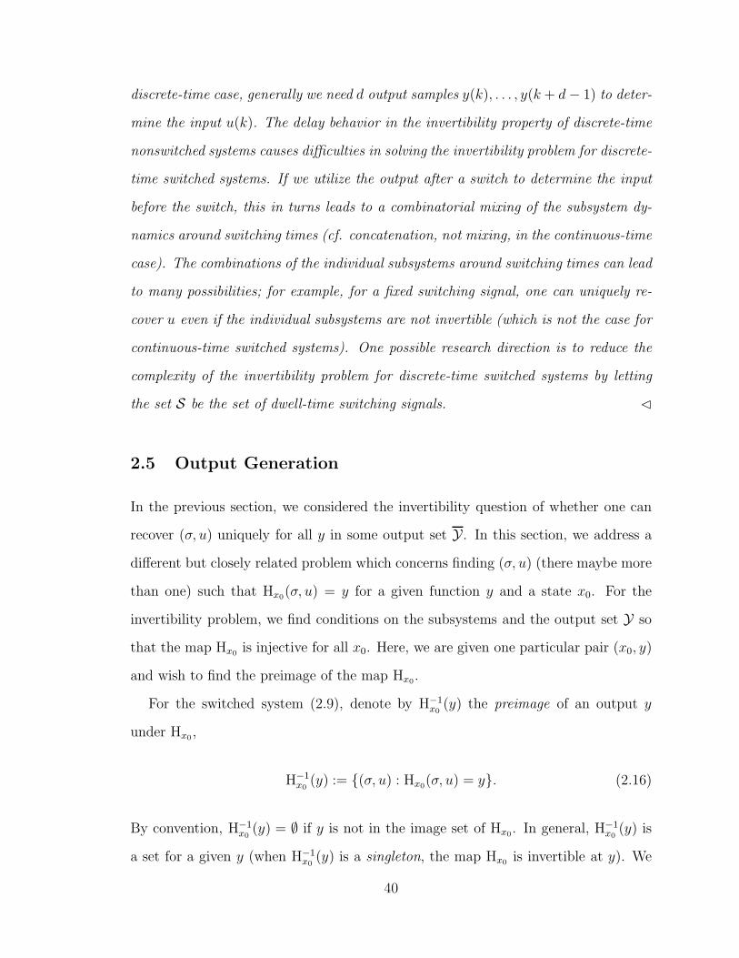
discrete-time case, generally we need d output samples y(k), . . . , y(k + d− 1) to deter-
mine the input u(k). The delay behavior in the invertibility property of discrete-time
nonswitched systems causes difficulties in solving the invertibility problem for discrete-
time switched systems. If we utilize the output after a switch to determine the input
before the switch, this in turns leads to a combinatorial mixing of the subsystem dy-
namics around switching times (cf. concatenation, not mixing, in the continuous-time
case). The combinations of the individual subsystems around switching times can lead
to many possibilities; for example, for a fixed switching signal, one can uniquely re-
cover u even if the individual subsystems are not invertible (which is not the case for
continuous-time switched systems). One possible research direction is to reduce the
complexity of the invertibility problem for discrete-time switched systems by letting
the set S be the set of dwell-time switching signals. ⊳
2.5 Output Generation
In the previous section, we considered the invertibility question of whether one can
recover (σ, u) uniquely for all y in some output set Y . In this section, we address a
different but closely related problem which concerns finding (σ, u) (there maybe more
than one) such that Hx0(σ, u) = y for a given function y and a state x0. For the
invertibility problem, we find conditions on the subsystems and the output set Y so
that the map Hx0 is injective for all x0. Here, we are given one particular pair (x0, y)
and wish to find the preimage of the map Hx0.
For the switched system (2.9), denote by H−1x0
(y) the preimage of an output y
under Hx0 ,
H−1x0
(y) := (σ, u) : Hx0(σ, u) = y. (2.16)
By convention, H−1x0
(y) = ∅ if y is not in the image set of Hx0. In general, H−1x0
(y) is
a set for a given y (when H−1x0
(y) is a singleton, the map Hx0 is invertible at y). We
40
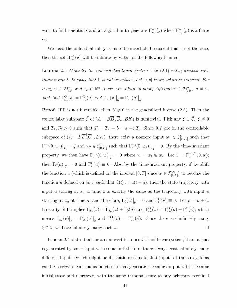
want to find conditions and an algorithm to generate H−1x0
(y) when H−1x0
(y) is a finite
set.
We need the individual subsystems to be invertible because if this is not the case,
then the set H−1x0
(y) will be infinite by virtue of the following lemma.
Lemma 2.4 Consider the nonswitched linear system Γ in (2.1) with piecewise con-
tinuous input. Suppose that Γ is not invertible. Let [a, b] be an arbitrary interval. For
every u ∈ Fpc[a,b] and xa ∈ Rn, there are infinitely many different v ∈ Fpc
[a,b], v 6= u,
such that ΓOxa
(v) = ΓOxa
(u) and Γxa(v)∣∣b= Γxa(u)
∣∣b.
Proof If Γ is not invertible, then K 6= 0 in the generalized inverse (2.3). Then the
controllable subspace C of (A − BD†
αCα, BK) is nontrivial. Pick any ξ ∈ C, ξ 6= 0
and T1, T2 > 0 such that T1 + T2 = b − a =: T . Since 0, ξ are in the controllable
subspace of (A − BD†
αCα, BK), there exist a nonzero input w1 ∈ C0[0,T1] such that
Γ−10 (0, w1)
∣∣T1
= ξ and w2 ∈ C0[0,T2]
such that Γ−1ξ (0, w2)
∣∣T2
= 0. By the time-invariant
property, we then have Γ−10 (0, w)
∣∣T
= 0 where w = w1 ⊕ w2. Let u = Γ−1,O0 (0, w);
then Γ0(u)∣∣T
= 0 and ΓO0 (u) ≡ 0. Also by the time-invariant property, if we shift
the function u (which is defined on the interval [0, T ] since w ∈ Fpc[0,T ]) to become the
function u defined on [a, b] such that u(t) := u(t− a), then the state trajectory with
input u staring at xa at time 0 is exactly the same as the trajectory with input u
starting at xa at time a, and therefore, Γ0(u)∣∣b
= 0 and ΓO0 (u) ≡ 0. Let v = u + u.
Linearity of Γ implies Γxa(v) = Γxa(u) + Γ0(u) and ΓOxa
(v) = ΓOxa
(u) + ΓO0 (u), which
means Γxa(v)∣∣b
= Γxa(u)∣∣b
and ΓOxa
(v) = ΓOxa
(u). Since there are infinitely many
ξ ∈ C, we have infinitely many such v.
Lemma 2.4 states that for a noninvertible nonswitched linear system, if an output
is generated by some input with some initial state, there always exist infinitely many
different inputs (which might be discontinuous; note that inputs of the subsystems
can be piecewise continuous functions) that generate the same output with the same
initial state and moreover, with the same terminal state at any arbitrary terminal
41

time T > 0. It is then clear that for a switched system with noninvertible active
subsystems, there are infinitely many inputs that generate the same output starting
from the initial state and with the same switching signal. The fact that invertibility
of all the subsystems is a necessary condition for invertibility of switched systems
(see Theorem 2.2) can also be inferred from Lemma 2.4. For our output generation
problem, we have the following corollary which states that if one active subsystem is
not invertible, then the set H−1x0
(y) will be infinite.
Corollary 2.1 Consider a function y = Hx0(σ, u) for some σ, u. Let Q ⊆ P be the
set of values of σ. If there exists q ∈ Q such that Γq is not invertible, then there exist
infinitely many u such that y = Hx0(σ, u).
The previous discussion motivates us to introduce the following assumption.
Assumption 2.1 The individual subsystems Γp are invertible for all p ∈ P.
However, we have no other assumption on the subsystem dynamics and the switched
system may not be invertible as the subsystems may not satisfy the invertibility
condition in the previous section. Since we look for an algorithm to find H−1x0
(y), we
only consider the functions y of finite intervals (and hence, there is a finite number of
switches) to avoid infinite loop reasoning when there are infinitely many switchings.
At a quick glance, it seems that one solution is straightforward: switchings occur
at times when the output loses continuity and since we have finite numbers of systems
and switches, there is a finite number of possible switching signals and an exhaustive
search would suffice (cf. the motivating example in the introduction). However, this
is far from being the only case because we can have a switching and the output is still
smooth at that switching time, and likewise, we can have no switching even if the
output looses continuity (because we allow discontinuous inputs for the subsystems
and we allow y to depend directly on u through D). As we shall see, it is possible
to use a switch at a later time to recover a “hidden switch” earlier (e.g., a switch at
42

which the output is smooth) and this phenomenon is peculiar to switched systems
with no counterpart in nonswitched systems.
We now present a switching inversion algorithm for switched systems that returns
H−1x0
(y) for a function y ∈ FpcD where D is a finite interval, when H−1
x0(y) is a finite set.
The parameters to the algorithm are x0 ∈ Rn and y ∈ FpcD , and the return is H−1
x0(y)
as in (2.16). In the algorithm, “←” reads “assigned as,” and “:=” reads “defined as.”
Define the index-matching map2 Σ−1 : Rn ×Fpc → 2P as
Σ−1(x0, y) := p : y ∈ Yp and Npy|t+0 = Lpx0, (2.17)
where t0 is the initial time of y. The index-matching map returns the indexes of the
subsystems that are capable of generating y starting from x0. If the returned set
is empty, no subsystem is able to generate that y starting from x0. Note that the
index-matching map Σ−1 in (2.17) is defined for every pair (x0, y) and always returns
a set, whereas the index inversion function Σ−1
in (2.13) is defined for nonsingular
pairs only and returns an element of P.
Algorithm
Begin of Function H−1x0
(y)
Let the domain of y be [t0, T ).
Let P := p ∈ P : y[t0,t0+ε) ∈ Yp for some ε > 0.Let t∗ := mint ∈ [t0, T ) : y[t,t+ε) /∈ Yp
for some p ∈ P, ε > 0 or t∗ = T otherwise.
Let P∗ := Σ−1(x0, y[t0,t0+ε)) for sufficiently small ε.
If P∗ 6= ∅,
Let A := ∅.For each p ∈ P∗,
Let u := Γ−1,Op,x0
(y[t0,t∗)),
2The symbol 2P denotes the set of all subsets of a set P.
43

T := t ∈ (t0, t∗) : (x(t), y[t,t∗)) is
a singular pair of Γp,Γq for some q 6= p.
If T is a finite set,
For each τ ∈ T , let ξ := Γp(u)(τ).
A ← A∪ (σp[t0,τ), u[t0,τ))⊕H−1
ξ (y[τ,T ))End For each
Else If T = ∅ and t∗ < T , let ξ = Γp(u)(t∗).
A ← A∪ (σp[t0,t∗), u)⊕H−1
ξ (y[t∗,T ))
Else If T = ∅ and t∗ = T ,
A ← A∪ (σp[t0,T ), u)
Else
A := ∅
End If
End For each
Else
A := ∅
End If
Return H−1x0
(y) := AEnd of Function
The idea behind the algorithm is based on the following relationship:
H−1x0
(y[t0,T )) = (σ, u)⊕ H−1Hx0(σ,u)(t)(y[t,T )),
(σ, u) ∈ H−1x0
(y[t0,t)) ∀t ∈ [t0, T ), (2.18)
which follows from the fact that Hx0(σ[t0,T ), u[t0,T ))(t) = Hx(s)(σ[s,T ), u[s,T )), x :=
Γx0,σ[t0,s)(u[t0,s)) ∀s ∈ [t0, T ), ∀t > s (this is known as the semigroup property for tra-
jectories of dynamical systems). Basically, (2.18) means that we can do the preimage
determination on a subinterval [t0, t) of [t0, T ) and then concatenate these with the
44

corresponding preimage on the rest of the interval [t, T ). Now, if t in (2.18) is the first
switching time after t0, then we can find H−1x0
(y[t0,t)) by singling out which subsystems
are capable of generating y[t0,t) using the index-matching map (2.17). So the problem
comes down to determining the first switching time t (and then the procedure is re-
peated for the function y[t,T )). The concept of singular pairs helps to identify possible
switching times when there is no irregularity at the output (e.g., when the output is
smooth at a switching time).
In light of the discussion in the previous paragraph, it is noted that the switching
inversion algorithm is a recursive procedure calling itself with different parameters
within the main algorithm (e.g., the function H−1x0
(y) uses the returns of H−1ξ (y[τ,T ))).
There are three stopping conditions: it terminates either when P∗ = ∅, in which case
there is no subsystem that can generate the output y at time t0 starting from x0,
or when T is not a finite set, in which case we cannot proceed because of infinitely
many possible switching times, or when T is an empty set and t∗ = T , in which case
the switching signal is a constant switching signal.
If the algorithm returns a nonempty set, the set must be finite and this set contains
pairs of switching signals and inputs that generate the given function y starting from
x0. If the algorithm returns an empty set, it means that there is no switching signal
and input that generate y, or there is an infinite number of possible switching times
(it is possible to further distinguish between these two cases by using an extra variable
in the algorithm that is assigned different values for the different cases). Notice the
utilization of the concatenation notation here: if at any instant of time, the return of
the procedure is an empty set, then that branch of the search will be empty because
f ⊕ ∅ = ∅.
Remark 2.12 When y ∈ Fn and the input and output dimensions are the same,
then t∗ in the algorithm can be simplified to be the first discontinuity of y in [t0, T )
(or t∗ = T if y is continuous). That is because in this case, Cn functions are always
45

in Yp for all p ∈ P (see Remark 2.2) and thus, P = P, and y[t,t+ε) /∈ Yp only if y is
discontinuous at t. ⊳
2.6 Examples
In this section, we provide detailed examples to illustrate our results. The first one
is an example of an invertible switched system. The second example illustrates the
use of the switching inversion algorithm on a noninvertible switched system.
Example 2.1 Consider the switched system generated by the following two subsys-
tems:
Γ1 :
x=
1 2
3 4
x+
1
2
u,
y =[0 1
]x,
Γ2 :
x=
3 1
5 4
x+
1
3
u,
y =[0 2
]x.
Using the structure algorithm, we can check that the two systems are invertible. In
this case, the operators N1,N2 are matrix operators and
N1 = W1 =[1
], L1 =
[0 1
],
N2 = W2 =[1
], L2 =
[0 2
].
In this example, the input and output dimensions are the same. We have
Rank
W1 L1
W2 L2
= Rank
W1
W2
+ Rank
L1
L2
.
By Theorem 2.2, we conclude that the switched system generated by Γ1,Γ2 is
invertible on Y := y ∈ Fpc :
W1
W2
y|t+ 6= 0 ∀t = y ∈ Fpc : y(t) 6= 0 ∀t.
46

Example 2.2 We return to the example in the introduction. Using the structure
algorithm, we can check that the two systems are invertible. We have
N1 = W1 =[1
], L1 =
[0 1
],
N2 = W2 =[1
], L2 =
[1 2
].
The rank condition is violated (Rank[W1,2 L1,2
]= 2 6= Rank W1,2 + Rank L1,2 =
3), and hence, the switched system generated by Γ1, Γ2 is not invertible. Consider
the output
y(t) =
2e2t − 3et, if t ∈ [0, t∗),
c1et + c2e
2t, if t ∈ [t∗, T ),
where t∗ = ln 3, T = 6/5, c1 = 15 + 18 ln(2/3), c2 = −4/3− 4 ln(2/3) and the initial
state x0 = (−1, 0)T .
We now illustrate how the inversion algorithm works. In this example, y is piece-
wise smooth and the subsystems’ input and output dimensions are the same, so t∗
in the algorithm coincides with t∗ in the definition of y (see Remark 2.12). We have
P∗ := Σ−1(x0, y[0,t∗)) = 2 by using the index-matching procedure (2.17) with x0
and y(0) = −1. The structure algorithm for Γ2 on [0, t∗) yields the inverse
Γ−12 :
z =
0 4
0 −2
z +
−1
1
y,
u(t) = y −[−1 4
]z,
t ∈ [0, t∗)
47

with z(0) = x0, which then gives
z(t) =
−et
−et + e2t
=: x(t),
u(t) = 0,
t ∈ [0, t∗). (2.19)
We want to find T = t 6 t∗ : (x(t), y[t,t∗)) is a singular pair of Γ1,Γ2, which is
equivalent to solving W1y(t) = L1x(t) (since we already have W2y(t) = L2x(t) ∀t ∈
[0, t∗)). This leads to the equation
2e2t − 3et = x2(t) = −et + e2t, t ∈ [0, t∗).
The foregoing equation has a solution t = ln 2 =: t1 < t∗, and hence, T = t1, which
is a finite set. We have ξ = x(t1) = (−2, 2)T and we repeat the procedure for the
initial state ξ and the output y[t1,T ). Now P∗ = Σ−1(ξ, y[t1,t∗)) = 1, 2.
• Case 1: p = 1. Using the structure algorithm, we obtain the inverse system of
Γ1,
Γ−11 :
z =
1 1
0 0
z +
1
1
y,
u = y −[0 −1
]z,
with the initial state z(t1) = ξ, which yields
z(t)=
(−13+6 ln 2)et + 6e2t−6tet
2e2t − 3et
=:x(t),
u(t) = 6e2t − 6et,
t > t1.
We find T = t1 < t 6 t∗ : (x(t), y[t,t∗)) is a singular pair of Γ1,Γ2, which is
48

equivalent to solving
W2y(t) = 2e2t − 3et
= L2x(t) = (−19 + 6 ln 2)et + 10e2t − 6tet
for t1 < t 6 t∗. It is not difficult to check that the foregoing equation does not
have a solution. We then let ξ = x(t∗) = (15 + 18 ln(2/3), 9) and repeat the
procedure with ξ and y[t∗,T ), which yields the unique solution σ = σ2[t∗,T ) and
u[t∗,T ) = 0.
• Case 2: p = 2. This case means that t1 is not a switching time. Then u(t) = 0
up to time t∗ by the structure algorithm, and hence,
x(t) =
−et
−et + e2t
, τ 6 t 6 t∗,
in view of (2.19). We then repeat the procedure with ξ = x(t∗) = (−3, 6)
and y[t∗,T ). We have y(t∗) = 33 + 18 ln(2/3), and since L1ξ /∈ W1y(t∗) and
L2ξ /∈W2y(t∗), the index-matching map returns an empty set, Σ−1(ξ, y[t∗,T )) = ∅.
Thus, the switching inversion algorithm returns (σ, u), where
σ(t) = σ2[0,t1) ⊕ σ1
[t1,t∗) ⊕ σ2[t∗,T ),
u(t) =
0, if 0 6 t < t1,
6e2t − 6et, if t1 6 t < t∗,
0, if t∗ 6 t 6 T.
As we can see, the output loses smoothness at t∗ and t∗ is a switching time.
However, there is another switching at t1 < t∗ whilst the output is smooth at t1.
Thus, without the concept of singular pairs, one might falsely conclude that there is no
switching signal and input after trying all the obvious combinations of the switching
49

signals (i.e., σ = σi[0,t∗) ⊕ σj
[t∗,T ), i, j ∈ 1, 2). Here, using the switching inversion
algorithm, we can recover the switching signal and in this case, the switching signal
and input are unique. This clearly demonstrates the usefulness of the singular-pair
concept.
2.7 Robust Invertibility
Note that the index matching function (2.13) requires exact knowledge of the initial
state x0 and the output y. To to handle disturbances, we replace this inversion map
(2.13) with the following map that returns the index with minimum cost. Define the
function
Σ−1 : (x0, y) 7→ argminp∈P ‖Npy|t+0 − Lpx0‖. (2.20)
We say that the switched system is robustly invertible with radius ε if
1. every subsystem has a stable inverse, and
2. a small disturbance of magnitude ε does not affect our detection algorithm, i.e.,
Σ−1(x0, y) = Σ−1
(x0, y) (2.21)
for all x0 ∈ Rn, y ∈ Y , ‖x− x‖ < ε, ‖Npy −Npy‖ < ε, p ∈ P.
Now (2.21) implies that we are able to recover the correct switching signal even in the
face of disturbances. If the subsystem has a stable inverse, then the state estimation
error |z − x|, where z as in (2.15), will asymptotically go to zero even if the initial
state z(0) 6= x0, provided that the initial error is small enough and the switching
signal is slow enough in the dwell-time or average dwell-time sense (see Section 3.2
for the definition of average dwell-time).
50

Proposition 2.1 Consider the switched system (2.9) and the output set Y. Suppose
that switched system is robustly invertible with radius ε. There exists a number δ > 0
and a class of switching signal Saverage[τa, N0] such that if the initial state error is
less than δ, then the switching signal can be reconstructed exactly and the input can
be recovered asymptotically for all switching signals in Saverage[τa, N0].
2.8 Discrete-Time Switched Systems
In this section, we address the invertibility problems for discrete-time switched lin-
ear systems. Consider a discrete-time switched linear system Γσ with the family of
subsystems Γp, p ∈ P,
Γσ :
x(k + 1) = Aσ(k)x(k) +Bσ(k)u(k),
y(k) = Cσ(k)x(k) +Dσ(k)u(k).(2.22)
We assume that the the individual subsystems live in the same state space Rn. The
discrete-time switching signal σ is a function σ : 0, 1, 2, . . . → P; switching times
are k such that σ(k) 6= σ(k−1), k > 1. Denote by S the set of discrete-time switching
signals. Unlike the case of continuous-time switching signals, we do not have further
restrictions on σ because a discrete-time signal already implies that there can only be
finitely many switches in any finite interval. The input set U is the set of functions
mapping 0, 1, 2, . . . into a value in the input spaces. A switching signal σ ∈ S
and an input u ∈ U are compatible if dim(u(k)) = mσ(k), where mi, i ∈ P are the
input dimensions of the individual subsystems. We assume that there is no jump at
switching times. For each initial state x0 ∈ Rn, a compatible (σ, u), σ ∈ S, u ∈ U ,
a unique trajectory of the switched system exists and is denoted by Γσ,x0(u); the
corresponding output is ΓOσ,x0
(u).
51

2.8.1 Input invertibility
In this subsection, we consider the input invertibility problem, which concerns with
recovering the input from the output of switched systems with known switching sig-
nals. For the continuous-time case, as we have seen, input invertibility is equivalent
to invertibility of the individual subsystems (a consequence of Lemma 2.4). For the
discrete-time case, we do not have the analogy of Lemma 2.4 (unless the switching
signal has the minimum dwell-time no less than 2n), and invertibility of the individual
subsystems is neither necessary nor sufficient (see Example 2.4 below).
We now present an extension of the structure algorithm to discrete-time switched
linear systems, which shall be called the hybrid structure algorithm. This algorithm
is essentially the structure algorithm for time-varying linear systems and is compli-
mentary to the other approach on input invertibility of discrete-time systems [17, 38]
which use the whole past output data, whereas here we only use partial past output
data. The name hybrid structure algorithm reflects the fact that the time-varying
system matrices only take a finite number of possible matrices, compared to the case
of general time-varying systems where there is no restriction on the system matrices.
When the switching signal is a constant switching signal, the algorithm reduces to
those of discrete-time nonswitched systems, which is numerically the same as those
for continuous-time algorithms except that differentiations are replaced by delay op-
erators.
The hybrid structure algorithm
Let qσ(ℓ, 0) = rank(Dσ(ℓ)). There exists a nonsingular matrix Sσ(ℓ, 0) such that
Sσ(ℓ, 0)Dσ(ℓ) =
Dσ(ℓ, 0)
0
, where Dσ(ℓ, 0) has qσ(ℓ, 0) rows and rank qσ(ℓ, 0). Let
52

zσ(ℓ, 0) = Sσ(ℓ, 0)y(ℓ) and Cσ(ℓ, 0) = Sσ(ℓ, 0)Cσ(ℓ). Thus, we have
zσ(ℓ, 0) =
zσ(ℓ, 0)
zσ(ℓ, 0)
=
Cσ(ℓ, 0)
Cσ(ℓ, 0)
x(ℓ) +
Dσ(ℓ, 0)
0
u(ℓ). (2.23)
We also have
zσ(ℓ+ 1, 0) =
zσ(ℓ+ 1, 0)
zσ(ℓ+ 1, 0)
=
Cσ(ℓ+ 1, 0)
Cσ(ℓ+ 1, 0)
x(ℓ + 1) +
Dσ(ℓ+ 1, 0)
0
u(ℓ+ 1),
and hence,
zσ(ℓ+ 1, 0) = Cσ(ℓ+ 1, 0)Aσ(ℓ)x(ℓ) + Cσ(ℓ+ 1, 0)Bσ(ℓ)u(ℓ). (2.24)
From (2.23) and (2.24), we obtain
zσ(ℓ, 0)
zσ(ℓ+ 1, 0)
=
Cσ(ℓ, 0)
Cσ(ℓ+ 1, 0)Aσ(ℓ)
x(ℓ) +
Dσ(ℓ, 0)
Cσ(ℓ+ 1, 0)Bσ(ℓ)
u(ℓ)
=: Cσ(ℓ, 1)x(ℓ) +Dσ(ℓ, 1)u(ℓ).
Let qσ(ℓ, 1) = rankDσ(ℓ, 1) and Sσ(ℓ, 1) such that Sσ(ℓ, 1)Dσ(ℓ, 1) =
Dσ(ℓ, 1)
0
,
where the rows of Dσ(ℓ, 1) are linear independent. We have
zσ(ℓ, 1) := Sσ(ℓ, 1)
zσ(ℓ, 0)
zσ(ℓ+ 1, 0)
=
Cσ(ℓ, 1)
Cσ(ℓ, 1)
x(ℓ) +
Dσ(ℓ, 1)
0
u(ℓ). (2.25)
The foregoing equation also implies
zσ(ℓ+ 1, 1) =
Cσ(ℓ+ 1, 1)
Cσ(ℓ+ 1, 1)
x(ℓ + 1) +
Dσ(ℓ+ 1, 1)
0
u(ℓ+ 1).
53

and hence,
zσ(ℓ+ 1, 1) = Cσ(ℓ+ 1, 1)Aσ(ℓ)x(ℓ) + Cσ(ℓ+ 1, 1)Bσ(ℓ)u(ℓ). (2.26)
From (2.25) and (2.26), we obtain
zσ(ℓ, 1)
zσ(ℓ+ 1, 1)
=
Cσ(ℓ, 1)
Cσ(ℓ+ 1, 1)Aσ(ℓ)
x(ℓ) +
Dσ(ℓ, 1)
Cσ(ℓ+ 1, 1)Bσ(ℓ)
u(ℓ).
Continuing the described procedure, we have the following recursive definition of the
structure algorithm starting at time ℓ and after k steps:
Dσ(ℓ, 0) := Dσ(ℓ), Cσ(ℓ, 0) := Cσ(ℓ)
Dσ(ℓ, k) :=
Dσ(ℓ, k − 1)
Cσ(ℓ+ 1, k − 1)Bσ(ℓ)
, qσ(ℓ, k) := rankDσ(ℓ, k)
Sσ(ℓ, k)Dσ(ℓ, k) =
Dσ(ℓ, k)
0
, rank Dσ(ℓ, k) = qσ(ℓ, k)
Cσ(ℓ, k) :=
Cσ(ℓ, k − 1)
Cσ(ℓ+ 1, k − 1)Aσ(ℓ)
,
Sσ(ℓ, k)Cσ(ℓ, k) :=
Cσ(ℓ, k)
Cσ(ℓ, k)
, Cσ(ℓ, k) is the first qσ(ℓ, k) rows of Sσ(ℓ, k)Cσ(ℓ, k)
zσ(ℓ, k) := Sσ(ℓ, k)
zσ(ℓ, k − 1)
zσ(ℓ+ 1, k − 1)
=
Cσ(ℓ, k)
Cσ(ℓ, k)
x(ℓ) +
Dσ(ℓ, k)
0
u(ℓ)
zσ(ℓ, k) :=
zσ(ℓ, k)
zσ(ℓ, k)
, zσ(ℓ, k) is the first qσ(ℓ, k) rows of zσ(ℓ, k)
zσ(ℓ, 0) := Sσ(ℓ, 0)y(ℓ).
(2.27)
54

Remark 2.13 For nonswitched systems, σ(ℓ) = p ∀ℓ for some p ∈ P. Then
Cσ(ℓ, 0) = C, Dσ(ℓ, 0) = D ∀ℓ.
It follows that Dσ(ℓ, k) is independent of ℓ, and hence, Sσ(ℓ, k) and qσ(ℓ, k) are also
independent of the starting time ℓ. In particular, Cσ(ℓ + 1, k − 1) = Cσ(ℓ, k − 1),
which means that we do not need to calculate Cσ(ℓ+1, k−1) but can use the available
Cσ(ℓ, k − 1) (this is the nested feature in the structure algorithm for nonswitched
systems). In this case, the hybrid structure algorithm (2.27) is exactly the same as
the structure algorithm described in the appendix.
The hybrid structure algorithm produces a sequence of integers qσ(ℓ, 0) 6 qσ(ℓ, 1) 6
qσ(ℓ, 2) 6 . . . . The following notion of relative degree is an extension of the same
notion for nonlinear systems by Singh in [39] to discrete-time switched linear systems.
Definition 2.2 The relative degree Γrσ(ℓ) of the switched system (2.22) at a time ℓ
is the least integer k such that qσ(ℓ, k) = mσ(ℓ) or Γrσ(ℓ) =∞ if qσ(ℓ, k) < mσ(ℓ) ∀k =
0, 1, . . . , where mσ(ℓ) is the input dimension of the system Γσ(ℓ).
For nonswitched systems (i.e., σ is a constant switching signal), because of the
time-invariant property, the relative degree is time-invariant (see Remark 2.13) and
is denoted by Γr. For switched systems, the relative degree is not time-invariant; it is
time-dependent so we must talk of a relative degree at a time. Also, for nonswitched
systems, there is a lower bound k on k such that q(k) = q(k) ∀k > k. In fact, k 6 n,
where n is the state dimension (this follows from the Cayley-Hamilton theorem). This
means that we can determine whether Γr < ∞ or Γr = ∞ after at most n steps in
the algorithm. In contrast, for switched systems, we do not have such a lower bound
on k and in general, Γr =∞ means we have infinite steps in the algorithm (in certain
cases, for example, when there is a pattern in σ, we can still verify that Γrσ(ℓ) = ∞;
see Example 2.3 below). We have the following lemma.
55

Lemma 2.5 For a fixed switching signal σ, the discrete-time switched system (2.22)
is invertible if Γrσ(ℓ) <∞ ∀ℓ = 0, 1, . . . .
Proof The proof is straightforward from the hybrid structure algorithm and the
definition of a relative degree. If Γrσ(ℓ) < ∞, we have qσ(ℓ, k) = mi for some k > 0,
which implies that the input u(ℓ) is uniquely recovered as u(ℓ) = D−1
σ (ℓ, k)(zσ(ℓ, k)−
Cσ(ℓ, k)x(ℓ)), where D−1
σ (ℓ, k) is the inverse of Dσ(ℓ, k). Since x(0) = x0 is known,
we can recover u(0). Then x(1) is known. Since Γrσ(1) < ∞, u(1) can be recovered
uniquely. It follows that x(ℓ), u(ℓ) are recovered uniquely for all ℓ > 0.
Lemma 2.5 is a sufficient condition for input invertibility. Whether this condition
is necessary or not remains an open question. Notice that, in the case of nonswitched
systems, Γr <∞ is both necessary and sufficient for invertibility (Γr <∞ is equiva-
lent to qα = m in the appendix).
Example 2.3 Consider the following two systems:
Γ1 :
x(k + 1) =
1 1
0 1
x(k) +
1
1
u(k)
y(k) =[1 0
]x(k)
,
Γ2 :
x(k + 1) =
1 −1
0 1
x(k) +
0
1
u(k)
y(k) =[1 −1
]x(k)
.
For the nonswitched system Γ1, we have C1B1 = 1, and hence Γ1 is invertible.
Similarly, Γ2 is invertible. Consider the switched system generated by Γ1,Γ2 with the
switching signal σ = 1, 2, 1, 2, 1, 2 . . ..
Using the hybrid structure algorithm, we can see that C(0, k) = C1, D(0, k) = 0,
and qσ(0, k) = 0 ∀k > 0. Hence, Γrσ(0) =∞. It can be shown that Γr
σ(ℓ) =∞ ∀ℓ > 0.
The switched system is not invertible because it can be checked by direct substitutions
56

that ΓOσ,x0
(u) = y for all u where y(ℓ) :=[1 0
]x0 ∀ℓ > 0.
Example 2.4 Consider the following two subsystems:
Γ1 :
x(k + 1) =
1 0
0 1
x(k) +
1
0
u(k)
y(k) =[0 1
]x(k)
,
Γ2 :
x(k + 1) =
1 1
0 1
x(k) +
0
1
u(k)
y(k) =[1 0
]x(k)
.
The system Γ1 is not invertible. To see this, we have y(1) = C1x(1) = C1A1x0 +
C1B1u0 = C1x0, and it can be shown that y(k) = C1x0 ∀k > 0. Thus, the system
Γ1 is not invertible. By a similar analysis, it can be shown that Γ2 is not invertible.
Consider the switched system generated by Γ1,Γ2 with the switching signal σ =
1, 2, 1, 2, . . .. Using the hybrid structure algorithm, we can calculate that Γrσ(0) =
1 < ∞. Similarly, we calculate that Γrσ(1) = 1. It can then be verified that Γr
σ(ℓ) =
1 <∞ ∀ℓ > 0 and by Lemma 2.5, u(ℓ), x(ℓ) can be recovered uniquely for all ℓ. Here,
we see that the input of the switched system can be recovered uniquely for all output
y even though the individual subsystems are not invertible.
2.8.2 Invertibility
The invertibility problem for discrete-time switched systems is formulated similarly
as those for the continuous-time case but there is a difference in that, for discrete-time
systems, delay plays an important role in invertibility.
Problem 2.1 Consider a (switching signal × input)-output map Hx0 : S×U → Y for
the discrete-time switched system (2.22). For a number d > 0, find a largest possible
set Y and a condition on the subsystems, independent of x0, such that y1[0:k] = y1
[0:k] ⇒
57

u1[0:k−d] = u2
[0:k−d] for all k > d.
It is worth mentioning that the case of discrete-time switched linear systems is
not parallel to the continuous-time counterpart, and we have not yet obtained a
necessary and sufficient condition for invertibility of discrete-time switched linear
systems (we do have a sufficient condition and a necessary condition separately).
The difficulty arises from the essential difference between invertibility of discrete-
time nonswitched linear systems and their continuous-time counterparts, although the
invertibility conditions are exactly the same for the two cases. For the continuous-time
case, the information in an infinitesimally small interval y[t,t+δ), δ > 0, completely
determines u(t). In contrast, for the discrete-time case, generally we need d-samples,
1 6 d 6 n, y(k), . . . , y(k + d− 1), to determine the input u(k). The delay behavior
in the invertibility property of discrete-time nonswitched systems causes difficulties in
solving the invertibility problem for discrete-time switched systems. That is because
it is not always possible to recover all the inputs in between consecutive switching
times just using the outputs in the same interval when the individual subsystems are
invertible; i.e., u(k), . . . , u(k +N) cannot all be recovered from y(k), . . . , y(k +N)
given σ(k) = · · · = σ(k + N) = p (cf. the continuous-time case). If we utilize the
output after a switch to determine the input before switching, this in turns leads to
a combinatorial mixing of the subsystem dynamics around switching times (cf. the
concatenation (not mixing) in the continuous-time case). The combinations of the
individual subsystems are hard to characterize as they can lead to many possibilities:
for a fixed switching signal, one can lose invertibility of the switched system even
if the individual subsystems are invertible, and one can gain invertibility even if the
individual subsystems are not invertible (see Examples 2.3 and 2.4 below; cf. Theorem
2.2 for the continuous-time case).
A necessary condition that is easy to see (by picking constant switching signals)
is that the individual subsystems must be invertible.
58

Lemma 2.6 If the map Hx0 is invertible, it is necessary that Γp are invertible for all
p ∈ P.
A sufficient condition is more complicated. We consider the case d = 0. The
instant identification property is characterized as follows, which is the discrete-time
counterpart of the singular pair notion of continuous-time systems.
Definition 2.3 A pair (x0, z), x0 ∈ Rn, z ∈ Rm is a singular pair for the two systems
Γp,Γq with zero delay if the output dimensions of the two systems are both m and
further, there exist u1(0), u2(0) such that Cpx0 +Dpu1(0) = Cqx0 +Dqu2(0) = z.
Similarly to the continuous-time case, a singular pair for discrete-time systems
means that we cannot distinguish between the two systems just by looking at the
current output and the current state (it may be possible to distinguish between the
two if more outputs are taken into account but here we aim for instant identification).
Conversely, if (x0, z) is not a singular pair, we can immediately determine which
system is able to generate z starting from x0 (cf. the continuous-time case). We
now develop a formula to check if (x0, z) is a singular pair with zero delay. The
equation Cpx0 +Dpu1(0) = Cqx0 +Dqu2(0) = z contains u, so we have to find a way
to eliminate u from the equations. From the structure algorithm, we have
Sp
Sp
z =
Sp
Sp
Cpx0 +
Sp
Sp
Dpu1(0) =:
[CpCp
]x0 +
Dp
0
u1(0)
for some nonsingular matrix Sp such that SpDp = Dp, where rank(Dp) = rank(Dp)
(Sp is the matrix Sp(0, 0) in the algorithm). So if Spz = Cpx0, we can always find
u1(0) such that Cpx0 + Dpu1(0) = z (since Dp is full rank). Define Sq, Cq similarly
for the system Γq. Then (x0, z) is a singular pair iff it is a solution to the following
59

equation:
Sp
Sq
z =
Cp
Cq
x0. (2.28)
Similarly to the continuous-time case, we define the set Rp,q(z) be the set of points
x ∈ Rn such that (x, z) forms a singular pair,
Rp,q(z) := x ∈ Rn : (x, z) is a singular pair for Γp,Γq. (2.29)
By convention, Rp,q(z) = ∅ if the output dimensions of Γp,Γq are different. We have
described the instant identification property. The instant recovery property, which
shall be called invertible with order 0, is formally defined as follows.
Definition 2.4 The system Γp is invertible with order 0 if rank(Dp) is equal the input
dimension.
For the sake of presentation, assume that the output dimensions of the individual
subsystems are the same. Let Y be the set of output functions such that Y = y :
y(k) ∈ Y ′. We then now have a sufficient condition for invertibility of discrete-time
switched linear systems.
Lemma 2.7 Consider a discrete-time switched systems generated by Γp, p ∈ P.
The switched system is invertible on Y if every subsystem is invertible with order 0
and Rp,q(z) = ∅ ∀p, q ∈ P, p 6= q, ∀z ∈ Y ′.
Proof Because Rp,q(z) = ∅ ∀p, q ∈ P, p 6= q∀z ∈ Y ′, it follows that (x0, y(0)) is
not a singular pair for any Γp,Γq, p 6= q. Therefore, the index σ(0) = p is recovered
uniquely such that Spy(0) = Cpx0. Then u(0) is recovered uniquely from x0 and y(0)
since Γp is invertible with order 0. We then have x(1) = Apx0 + Bpu(0) is known.
Since (x(1), y(1)) is not a singular pair for any Γp,Γq, p 6= q, the index σ(1) = q is
recovered uniquely such that Sqy(1) = Cqx(1). Then u(1) is recovered uniquely from
60

x(1) and y(1) since Γq is invertible with order 0. Repeating this procedure, we can
see that σ(ℓ), u(ℓ), and x(ℓ) are recovered uniquely for all ℓ > 0.
Remark 2.14 We have presented a sufficient condition for invertibility of discrete-
time switched systems with respect to the whole switching signal S (i.e., arbitrary
switching), using the instant identification and instant recovery properties. The in-
stant identification property can be seen as 0-order identification, and the instant
recovery property can be seen as 0-order invertibility. These notions can be extended
to k-order identification and k-order invertibility where one can use up to k additional
output samples instead of only the current output. To employ these properties, one
may need to consider the invertibility problem on a smaller class of switching signals,
such as those with the minimum dwell-time of at least k samples. We do not have a
result on this and this can be a topic of further research.
We present an example of an invertible discrete-time switched linear system below.
Example 2.5 Consider switched systems generated by the two subsystems
Γ1 :
x(k + 1) =
1 1
0 2
x(k) +
2
0
u(k)
y(k) =
2 1
1 0
x(k) +
1
0
u(k)
,
Γ2 :
x(k + 1) =
1 2
4 3
x(k) +
2
3
u(k)
y(k) =
1 1
3 1
x(k) +
1
1
u(k)
.
We have S1 =[0 1
], S2 =
[−1 1
], C1 =
[1 0
], C2 =
[2 0
]. We then calculate
61
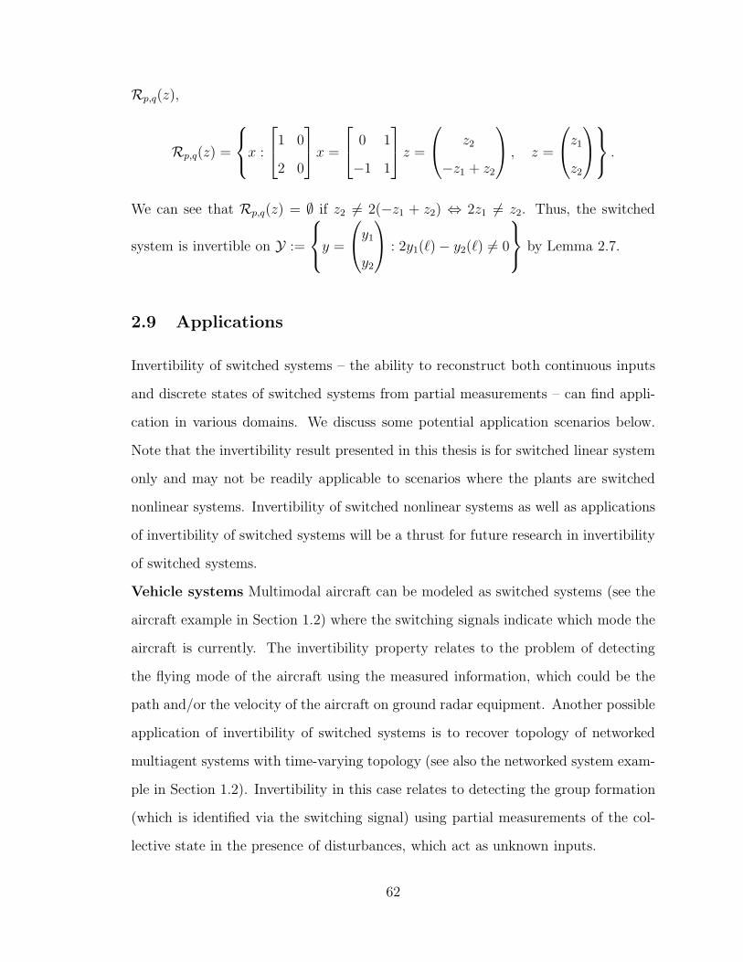
Rp,q(z),
Rp,q(z) =
x :
1 0
2 0
x =
0 1
−1 1
z =
z2
−z1 + z2
, z =
z1z2
.
We can see that Rp,q(z) = ∅ if z2 6= 2(−z1 + z2) ⇔ 2z1 6= z2. Thus, the switched
system is invertible on Y :=
y =
y1
y2
: 2y1(ℓ)− y2(ℓ) 6= 0
by Lemma 2.7.
2.9 Applications
Invertibility of switched systems – the ability to reconstruct both continuous inputs
and discrete states of switched systems from partial measurements – can find appli-
cation in various domains. We discuss some potential application scenarios below.
Note that the invertibility result presented in this thesis is for switched linear system
only and may not be readily applicable to scenarios where the plants are switched
nonlinear systems. Invertibility of switched nonlinear systems as well as applications
of invertibility of switched systems will be a thrust for future research in invertibility
of switched systems.
Vehicle systems Multimodal aircraft can be modeled as switched systems (see the
aircraft example in Section 1.2) where the switching signals indicate which mode the
aircraft is currently. The invertibility property relates to the problem of detecting
the flying mode of the aircraft using the measured information, which could be the
path and/or the velocity of the aircraft on ground radar equipment. Another possible
application of invertibility of switched systems is to recover topology of networked
multiagent systems with time-varying topology (see also the networked system exam-
ple in Section 1.2). Invertibility in this case relates to detecting the group formation
(which is identified via the switching signal) using partial measurements of the col-
lective state in the presence of disturbances, which act as unknown inputs.
62

Biological systems Systems approach to biology is one of the fastest growing trends
in biology, bringing the systematic view of engineering into the wealth of empirical
data available in biology in order to better understand how biological systems behave
within themselves and among a collection of systems [40, 41]. Among dynamical
system tools, hybrid dynamical systems are particularly suited to model biological
systems due to the inherent presence of switching mechanisms in biological systems
[42, 43, 44]. For example, in cell biology, gene activation and inhibition alter the
dynamics of chemical concentrations in cells, giving rise to hybrid models that in-
volve switching among multiple dynamics [45, 46, 47]. One potential application of
hybrid invertibility in the context of cell biology means the possibility of detecting
certain genes’s behaviors according to the active mode of a hybrid system model
(which is identified by the switching signal) in the presence of disturbances (which
act as unknown inputs) using measurements of concentration of proteins, mRNA, or
metabolites as the output.
Power networks The use of hybrid modeling tools in power networks can be found
in [48, 49, 50]. Switches are inherent in power networks and when there is a sig-
nificant change in the power load, for example when there is power surge or power
outage, switches/fuses will be active resulting in changes of the network dynamics. In
such events, it is essential to detect when power dynamics change and adjust power
distribution to recover stability. Understanding the invertibility property of hybrid
systems could lend a hand on the problem of identifying times of critical events using
partial measurements of power or voltage (which act as outputs).
Communication networks A communication network consists of a number of
nodes and there are data packets flowing along communication links between nodes.
To avoid congestion, network traffic is regulated by transmission control protocols
(TCPs), which tell nodes to drop packets if there is excessive incoming data compared
to outgoing data. When dropping occurs, dynamics of the nodes change abruptly and
this fact leads to the use of hybrid system to model communication networks [13, 14].
63

From the analysis point of view, one may want to detect changes in network dynam-
ics, maybe due to intrusion and attacks, using observed information. From security
point of view, one may want to design a hybrid system in such a way that the system
is not invertible to avoid letting others know its operating modes.
2.9.1 Topology recovery in multiagent networked systems
We present one application of invertibility of switched systems in recovering topol-
ogy of multiagent networked systems (see the multiagent example in Section 1.2 for
background and more discussion). Consider a network of n dynamical agents. Let xi
be the state of agent i and its dynamics be x = fi(xi, ui) where ui is the input. In
networked systems, the input action on an agent can depend not only on the state
of the agent but also the states of other agents in the network. The agents can com-
municate with each other and the communication among the agents is captured by
a graph G — also known as a topology of the network — whose nodes are agents
and edges denote communication links between the agents. The graph G can be a
directed graph or not. Denote by Ni the neighborhood of agent i which consists of
all the agents who have communication with agent i. The control action on agent i
is then of the form ui = g(xi, xj , j ∈ Ni). The collective dynamics of the network
of all agents are obtained by putting all the dynamics of the agents together and the
state of the networked multiagent system is x = (x1, . . . , xn). We will consider the
topology recovery problem for two different types of networked multiagent systems
in the following examples.
Cooperative consensus network
Consider a network of agents with undirected topologies. Assume the agents are
static when there are no external inputs: xi = ui + di, where di is a disturbance, and
the control action on the agent is a consensus protocol ui =∑
j∈Ni(xj − xi) with the
64

aim of reaching a common value x∗ among all the agents, xi(t)→ x∗ as t→∞. The
collective dynamics of the network are
x = −L(G)x+ Ind, (2.30)
where L(G) = [lij ], lij =
−1 if j ∈ Ni, j 6= i,
|Ni| i = j
is the graph Laplacian of G, In is
the identity matrix with dimension n, and d = (d1, . . . , dn).
Suppose that the network topology is varying with time and taking values in a
set of topologies such that G : [0,∞) → G1, . . . , Gm. We then write the network
dynamics as a switched system
x = Aσx+ Ind, (2.31)
where σ(t) := p : G(t) = Gp and Ap := L(Gp), p ∈ 1, . . . , m =: P. Suppose that
we also have output observation coming out of the network
y = Cσx, (2.32)
where y = Cpx is the observation corresponding to topology Gp, p ∈ P. Our in-
vertibility result implies that if the switched system described by (2.31) and (2.32) is
invertible, then it is guaranteed that we can recover the active topology at every time
using only output measurement and the initial state, even if there are disturbances.
For example, consider a network switching between two topologiesG1 =
0 1 1
1 0 1
1 1 0
(the element aij of the matrix is 1 if there is a link between node i and node j
65

and the element is 0 otherwise) and G2 =
0 1 0
0 0 1
1 0 0
. If the output observation
with the topology G1 is y =
x1
x1 + x2
x3
and the output with the topology G2 is
y =
x2
x1 + x3
x1
, then the rank condition (2.11) is violated. However, if the output
observation with the topology G1 is y =
x1
x1 + x2
x3
and the output with the topology
G2 is y =
x2
x1 + x3
x1 + x2
, then the rank condition is satisfied and we can guarantee
topology recovery in the presence of disturbance for all output y such that y(t) 6= 0∀t.
Cooperative work processing
Consider the scenario where a network of agents cooperate to process work (which
is viewed as “fluid”). There is a stream of work going into the network at rate u(t)
and the network returns processed work via an output y. There is a central unit that
divides the incoming work into portions and delegates them to a number of agents.
Suppose that an agent can process work at a rate fi. An agent can also pass work
to other agents (to share work load or because the work needs to be done through
several stages, each of which is managed by particular agents) and it can also receive
work from others. The relationship among the agents is captured by a directed graph
G = [gij ]; gij = 1 when there is a directed link from node i to node j and gij = 0
66

otherwise; gii = 0 for all i. Then an approximated fluid model of agent i is
xi = −fi −∑
j:gij>0
zij + ui, (2.33)
where xi is the buffer length, fi is the processing rate, zij is the work agent i send to
agent j per unit time, and ui is the coming work rate to buffer i,
ui = βiBiu+∑
j:gji>0
zji, (2.34)
where βiBiu is a portion of the incoming work u delegated to agent i from the central
unit (if βi = 0 or Bi = 0, agent i does not receive work from the central unit). The
constants βi satisfy the constraint∑
i βiBiu = u. We assume that the agent can
process work at a constant rate (there are other models for the work processing rate
and fi is a function of xi in general)
fi = λiIxi>0 (2.35)
and work passing among the agents is at a rate proportional to the buffer length,
zij = wijxi. (2.36)
Let G = [gij ], gij = gijwij be the weighted directed graph (or digraph) obtained by
associating the weight wij on the graph G. Assuming that xi > 0 for all i, from
(2.33), (2.34), and (2.36), the overall dynamics of the network are then
x = A(G)x+Bu+ λ, (2.37)
67

where x = (x1, . . . , xn), A(G) = [aij ], aii = −∑j:gij>0wij and aij = gji, j 6= i,
B =
β1B1
...
βnBn
, and λ := (λ1, . . . , λn). The processed work is then returned to the
central unit and the central unit puts processed work out of the network as an output
y = Cx. (2.38)
We call a tuple (G, B, C, λ) a network configuration, denoted by CF . Now, suppose
that the central unit has several configurations CF1, . . . , CFm and the network can
change its configuration according to some criteria (such as work load). Then the
network can be represented by the switched system
x = Aσx+Bσu+ λσ,
y = Cpx,(2.39)
where Ap = A(Gp) and Bp = B, p = 1, . . . , m. If the switched system is invertible,
then one can recover the network configuration using just the output y and an initial
state, without knowing u.
Invertibility of networked systems has an interpretation in a security context. If
an intruder has access to both u and y, he or she may be able to do hybrid system
identification (see, e.g., [33]). Now, suppose that an intruder only knows the data rate
y directly coming out of the network and the initial state x(0) and have no knowledge
of u and σ. The intruder may know the configurations from product specifications
(e.g., from vendors). The intruder then wants to figure out under which configuration
the network is currently operating and utilizes this type of information to carry out
network attacks. In other words, the intruder wants to recover σ from y and x(0).
This scenario fits into the invertibility problem for switched systems described above.
68

CHAPTER 3
STABILITY OF SWITCHED SYSTEMS
3.1 Stability Definitions
One of the fundamental issues in control is stability of systems. There are different
kinds of stabilities (such as bounded input-bounded output stability or periodic-cycle
stability), but here we concern ourselves with stability of equilibria, in particular
asymptotic stability for autonomous switched systems and input-to-state stability
for switched systems with inputs.
Trajectories of autonomous nonswitched systems are parameterized by the initial
state. However, for autonomous switched systems, trajectories depend on both the
initial state and the switching signal. This fact leads to the major difference in the
study of switched system properties compared to nonswitched system properties in
that switched system properties need to be characterized over all possible initial states
as well as all possible switching signals in some class of switching signals. Otherwise,
if a property holds for only one fixed switching signal, a switched system becomes a
time-varying nonlinear system and switching behavior plays a minimal role.
We first cover the concept of equilibria for switched systems. Consider the au-
tonomous switched system
Γσ : x = fσ(x) (3.1)
where σ : [0,∞)→ P for some index set P. Assume that the switched system state
space is Rn.
Definition 3.1 A state x⋆ is an equilibrium of the switched system (3.1) if it has
the property that whenever the switched system starts at x⋆, the state will remain at
69

x⋆ for all future time and for all possible switching signals.
From the definition, it is clear that x⋆ is an equilibrium of a switched system if
and only if it is a common equilibrium of all the subsystems. Therefore, x⋆ is an
equilibrium of (3.1) if and only if fp(x⋆) = 0 ∀p ∈ P.
We assume that the switched system (3.1) has an equilibrium x⋆ and without loss
of generality, we assume that x⋆ = 0 (otherwise, the change of variable x ← x − x⋆
will move the equilibrium to the origin). Asymptotic stability for switched systems
is defined as follows.
Definition 3.2 Consider the switched system (3.1) with the origin being an equilib-
rium. The origin is asymptotically stable (AS) over a class of switching signal S if
there exists a class KL function β and x0 > 0 such that |x(t)| 6 β(|x(0)|, t) ∀t > 0
for all |x(0)| 6 x0 and for all σ ∈ S.
We say that the origin is globally asymptotically stable (GAS) if we can take x0 =∞.
We also have input-to-state properties for switched systems with inputs. Consider
a switched system with input
Γσ : x = fσ(x, v). (3.2)
Assume that the unforced switched system with v = 0 has an equilibrium x⋆ and
without loss of generality, assume that x⋆ = 0. Denote by U the set of all piecewise
continuous hybrid functions that can be inputs to the switched system (3.2). Local
input-to-state stability (local ISS) for switched systems is defined as follows (see [51]
for the definition of local ISS for nonswitched systems):
Definition 3.3 Consider the switched system (3.2) with the origin being an equilib-
rium of the unforced system. The origin is locally input-to-state stable (locally ISS)
over a class of switching signals S if there exist β ∈ KL, α, γ ∈ K∞, and x0, u > 0
such that for all x(0) such that |x(0)| 6 x0, for all σ ∈ S, and for all compatible
70

hybrid functions v ∈ U such that |v(t)| 6 u ∀t, we have
α(|x(t)|) 6 β(|x(0)|, t) + γ(‖v‖[0,t)
)∀ t > 0. (3.3)
When we can take x0 = ∞ and u = ∞, we say that the origin is ISS. The function
α can be taken to be the identity function without loss of generality; see, e.g., [8,
Lemma 4.2]. We use the above formulation of ISS for the sake of consistency with
other input-to-state definitions below. The following definitions introduce a quanti-
tative measure of the “stability margin” via exponentially weighted signals.
Definition 3.4 Consider the switched system (3.2) with the origin being an equilib-
rium of the unforced system. The origin is locally eλt-weighted input-to-state stable
(locally eλt-weighted ISS) over a class of switching signal S for some λ > 0 if ∃
α1, α2, γ ∈ K∞ and x0, u > 0 such that for all x(0) such that |x(0)| 6 x0, for all
σ ∈ S, and for all compatible hybrid functions v ∈ U such that |v(t)| 6 u ∀t > 0, we
have
eλtα1(|x(t)|) 6 α2(|x(0)|)+sups∈[0,t)
eλsγ(|v(s)|)
∀ t > 0. (3.4)
Definition 3.5 Consider the switched system (3.2) with the origin being an equilib-
rium of the unforced system. The origin is locally eλt-weighted integral input-to-state
stable (locally eλt-weighted iISS) over a class of switching signal S for some λ > 0 if
∃ α1, α2, γ ∈ K∞, and x0, u > 0, such that for all x(0) such that |x(0)| 6 x0, for all
σ ∈ S, and for all compatible hybrid functions v ∈ U such that |v(t)| 6 u ∀t > 0, we
have
eλtα1(|x(t)|) 6 α2(|x(0)|)+∫ t
0
eλτγ(|v(τ)|)dτ ∀ t > 0. (3.5)
When we can take x0 = 0 and u = 0, we say that the origin is eλt-weighted ISS/ eλt-
weighted iISS. The eλt-weighted ISS and eλt-weighted iISS properties generalize ISS
71

and iISS properties1 in the spirit of exponentially weighted induced norms considered
in [21]. While the ISS property characterizes stability in general, the eλt-weighted
ISS and eλt-weighted iISS properties characterize stability with a “stability margin”
λ (similarly to stability margin of linear systems), which is useful in quantitative
analysis (e.g., in supervisory control as we will see later).
If in a definition, the set S is the set of all admissible switching signals, then we
say that the property is true for arbitrary switching. It has been shown [53] that GAS
of the switched system (3.1) for arbitrary switching is equivalent to the existence of
a common Lyapunov function V : Rn → [0,∞) such that ∀x,
α1(|x|) 6 V (x) 6 α2(|x|)∂V
∂xfp(x) 6 −γ(|x|) ∀p ∈ P,
for some functions α1, α2, γ ∈ K∞. Likewise, ISS of the switched system (3.1) for
arbitrary switching is equivalent to the existence of a common ISS-Lyapunov function
V : Rn → [0,∞) such that ∀x, u,
α1(|x|) 6 V (x) 6 α2(|x|)∂V
∂xfp(x) 6 −ρ(|x|) + γ(|u|) ∀p ∈ P,
for some functions α1, α2, γ, ρ ∈ K∞ [54].
Finding conditions on the subsystems to guarantee stability for arbitrary switch-
ing is one of the research directions in switched systems. For autonomous switched
nonlinear systems, it has been shown that if the vector fields fp of the subsystems are
commutative, then one can construct a common Lyapunov function and thus con-
clude asymptotic stability of the switched system for arbitrary switching [55]. Other
more general conditions in terms of Lie algebra have been found; see [56] for details
and the references therein. In general, requiring the subsystems to have a common
1See [52] for the original definition of iISS.
72

Lyapunov function places a restriction on the structure of the subsystems.
Another research direction is to find classes of switching signals that still guar-
antee stability of switched systems but with fewer requirements on the subsystems.
Earlier work leads to the class of dwell-time switching signals that guarantee GAS for
any switched system with asymptotically stable linear subsystems [20]. For switch-
ing signals with dwell-time τd, every switching interval is at least τd or longer. Later,
dwell-time switching has been extended to average dwell-time switching [21], in which
one can have arbitrarily small switching intervals as long as fast switching is com-
pensated by slower switching later so that on average, the dwell-time is sufficiently
large. It has been shown [21] that under average dwell-time switching, one still can
guarantee GAS of autonomous switched linear systems with GAS subsystems. With
large enough average dwell-time, one can also guarantee ISS, eλt-ISS, and eλt-iISS
of switched linear systems with ISS subsystems [21]. Several results on stability
of switched nonlinear systems over the classes of dwell-time and average dwell-time
switching have been obtained [7, 21, 57, 58]. Results with dwell-time switching [7, 58]
do not impose conditions on the subsystem dynamics compared to those with aver-
age dwell-time switching [21, 57], but the set of switching signals with dwell-time
switching for stability of switched systems is smaller than that with average dwell-
time switching. This chapter aims to obtain stability for switched nonlinear systems
for larger classes of switching signals and with fewer requirements on the subsystems
than the results currently reported in the literature.
3.2 Dwell-Time and Average Dwell-Time Switching
A switching signal has dwell-time τd if two consecutive switches are separated by at
least τd units of time. Dwell-time switching has been used to guarantee asymptotic
stability of switched linear systems with asymptotically stable subsystems in the
following way: since each subsystem is asymptotically stable, for a subsystem Γp,
73

p ∈ P, if the subsystem starts at an initial state x0, there exists a finite time τp
so that for all t > τ , the subsystem state |x(t)| 6 ρ|x0| for some constant ρ < 1.
It follows that if we dwell on the active subsystems for at least τd where τd is the
supremum of all τp of the subsystems, then the switched system state will decay to
zero. Specifically, if |x(t)| 6 Ce−λt|x(0)| for all the subsystems, then for all switching
signals with dwell-time τd > lnC/(λ−λ0) for any λ0 ∈ (0, λ), the state of the switched
system satisfies |x(t)| 6 e−λ0t|x(0)| in view of the fact that Ce−(λ−λ0)τd 6 1 (see [20,
Lemma 2]).
Dwell-time switching has the advantage of having simple implementation. In prac-
tice, switching with a dwell-time τd can be easily attained by not allowing a switch
to happen if the elapsed time from the last switch is less than τd. The drawback is
that sometimes, dwelling on for constant amounts of time may lead to undesirable
results such as spikes in signal magnitude. Average dwell-time switching alleviates
the need of being in a particular mode for longer time in case one is able to switch to
another mode in evidence of new data being available. Shorter switching intervals are
compensated by longer switching intervals so that on average, the switching interval
is large enough. Specifically, a switching signal has an average dwell-time τa [21] if
Nσ(T, t) 6 N0 +T − tτa
∀T > t (3.6)
for some number N0 > 1. The number N0 is called a chatter bound. Note that
N0 = 1 implies that there is no more than one switched in interval less than τa, and
hence, is corresponding to dwell-time switching.
Denote by Sdwell[τd] the class of switching signals with dwell-time τd and by
Saverage[τa, N0] the class of switching signals with average dwell-time τa and chat-
ter bound N0.
74

3.3 Input-to-State Properties With Average Dwell-Time
Switching
For autonomous switched nonlinear systems with average dwell-time switching sig-
nals, the switched system state is asymptotically stable if the subsystems are asymp-
totically stable and certain assumptions on the Lyapunov functions of the subsystems
hold [21]. For switched nonlinear systems with inputs and dwell-time switching sig-
nals, a switched system is input-to-state stable (ISS) if the individual subsystems are
ISS [58]; see also [59, Section 5]. If the individual subsystems are integral input-to-
state stable (iISS), the switched system remains iISS with state-dependent dwell-time
switching signals [7].
We extend the nonlinear results in [21] to switched nonlinear systems with inputs,
similarly to the results for switched linear systems with inputs (also in [21]). When
the individual subsystems of a switched system are ISS and their ISS-Lyapunov func-
tions satisfy a suitable condition (which was also used in [21]), we show that for
switching signals with sufficiently large average dwell-time, the switched system has
ISS, exponentially weighted-ISS, and exponentially weighted-iISS properties. Unlike
the ISS result in [58] which relies on dwell-time switching, our result only requires
average dwell-time switching, which is a less stringent requirement. Compared to
state-dependent dwell-time switching employed in [7] which requires the knowledge
of the state, average dwell-time switching can be achieved using simple hysteresis-
based switching logics [21, 60].
Theorem 3.1 Consider the switched system (3.2). Suppose that there exist continu-
ously differentiable functions Vp : Rn → [0,∞), p ∈ P, class K∞ functions α1, α2, γ,
75

and numbers λ0 > 0, µ > 1 such that ∀ ξ ∈ Rn, η ∈ Rℓ, and ∀ p, q ∈ P, we have
α1(|ξ|) 6 Vp(ξ) 6 α2(|ξ|), (3.7)
∂Vp
∂ξfp(ξ, η) 6 −λ0Vp(ξ) + γ(|η|), (3.8)
Vp(ξ) 6 µVq(ξ). (3.9)
Let σ be a switching signal having average dwell-time τa.
(i) If τa >lnµ
λ, then the switched system (3.2) is ISS.
(ii) If τa >lnµ
λ0 − λfor some λ ∈ (0, λ), then the switched system (3.2) is eλt-
weighted ISS.
(iii) Ifτa >
lnµ
λ0 − λ(3.10)
for some λ ∈ (0, λ), then the switched system (3.2) is eλt-weighted iISS.
Proof For notational brevity, define Gba(λ) :=
∫ b
aeλsγ(|v(s)|)ds. Let T > 0 be an
arbitrary time. Denote by τ1, . . . , τNσ(T,0) the switching times on the interval (0, T )
(by convention, τ0 := 0, τNσ(T,0)+1 := T ). Consider the piecewise continuously differ-
entiable function
W (s) := eλ0sVσ(s)(x(s)). (3.11)
On each interval [τi, τi+1), the switching signal is constant. From (3.11) and (3.8),
W (s) 6 eλ0sγ(|v(s)|) ∀ s ∈ [τi, τi+1). Integrating both sides of the foregoing inequality
from τi to τ−i+1 and using (3.9) we arrive at
W (τi+1) 6 µW (τ−i+1) 6 µ(W (τi) +Gτi+1τi
(λ0)). (3.12)
76

Iterating (3.12) from i = 0 to i = Nσ(T, 0), we get
W (T−) 6 µNσ(T,0)
W (0) +
Nσ(T,0)∑
k=0
µ−kGτk+1τk
(λ0)
. (3.13)
From (3.10), for every δ ∈ [0, λ0 − λ− lnµ/τa], we have τa > lnµ/(λ0 − λ− δ), and
by virtue of (3.6), we get
Nσ(T, s) 6 N + (λ0 − λ− δ)(T − s)/lnµ ∀ s ∈ [0, T ].
Since Nσ(T, 0)− k − 1 6 Nσ(T, τk+1), it follows that
µNσ(T,0)−k 6 µ1+Ne(λ0−λ−δ)(T−τk+1), (3.14)
for all k = 0, . . . , Nσ(T, 0). Since λ+ δ < λ0, we have
Gτk+1τk
(λ0) 6 e(λ0−λ−δ)τk+1Gτk+1τk
(λ+ δ). (3.15)
From (3.13), (3.14), and (3.15), we then arrive at
α1(|x(T )|) 6 ce−(λ+δ)T (α2(|x0|) +GT0 (λ+ δ)), (3.16)
c := µ1+N , (3.17)
by virtue of (3.11), (3.7) and since x is continuous. Letting δ = 0 in (3.16), we obtain
(3.5) with α1 := α1, α2 := cα2, γ := cγ. From the definition of Gba(λ), we have
GT0 (λ+ δ)6
c1c
e(λ+δ−λ)T supτ∈[0,T )
eλτγ(|v(τ)|)
(3.18)
77

for every λ ∈ [0, λ+ δ) where c1 := c/(λ+ δ − λ). From (3.18) and (3.16), we obtain
α1(|x(T )|) 6 ce−(λ+δ)Tα2(|x0|)
+ c1e−λT sup
τ∈[0,T )
eλτγ(|v(τ)|)
∀T > 0.
(3.19)
Picking some δ ∈ (0, λ0 − λ − lnµ/τa), and letting λ = λ in (3.19), we have the
property (3.4) with α1 := α1, α2 := cα2, and γ := c1γ. If we let λ = 0, δ = 0 in
(3.19), we have the property (3.3) with α := α1, β(r, s) := ce−λsα2(r), and γ := cγ/λ
by the fact that supτ∈[0,T ) γ(|v(τ)|) 6 γ(‖v‖[0,T )
).
An immediate consequence of Theorem 3.1 is that for a switched system satisfying
(3.7), (3.8), and (3.9), if the input v is bounded, then the state x is bounded for
average dwell-time switching signals with average dwell-time τa satisfying (3.10). If
the input goes to zero, the average dwell-time switching implies global asymptotic
stability of the switched system.
Remark 3.1 If each individual subsystem is ISS, then for every p ∈ P there exist
functions α1,p, α2,p, γp ∈ K∞, numbers λ,p > 0, and ISS-Lyapunov functions Vp,
satisfying α1,p(|ξ|) 6 Vp(ξ) 6 α2,p(|ξ|) and ∂Vp
∂ξfp(ξ) 6 −λ,pVp(ξ) + γp(|η|) ∀ ξ ∈
Rn, η ∈ Rℓ; see [61, 51]. If the set P is finite or if the set P is compact and suitable
continuity assumptions onα1,p, α2,p, γp
p∈P
and λ,pp∈P with respect to p hold,
then (3.7) and (3.8) follow. The set of possible ISS-Lyapunov functions is restricted
by (3.9). This inequality does not hold, for example, if Vp is quadratic for one value
of p and quartic for another. If µ = 1, (3.9) implies that V = Vp, p ∈ P is a common
ISS-Lyapunov function for the family of the systems, and the switched system is ISS
for arbitrary switching (also called uniformly input-to-state stable [54]).
The result in this section relies on the existence of a constant µ as in (3.9). While
this constant is always possible for a family of quadratic ISS-Lyapunov functions
(such as in the case of linear subsystems), in general, requiring such constant µ for
78

a family of ISS-Lyapunov functions of nonlinear subsystems seems rather restrictive.
We will relax the constant µ to a function µ of |x| and want to find classes of switching
signals that still guarantee certain input-to-state properties of the switched systems.
In doing so, we introduce a more general way of classifying switching signals using
event profiles (compared to average dwell-time) and obtain stability results that are
more general than those reported in the literature.
3.4 Event Profiles
We wish to quantify switching signals without taking into account the actual switching
intervals and the switching times. The rationale behind this approach stems from
the need to characterize switching signals using coarser information while still being
useful in assuring certain properties of switched systems. Obviously, one has more
information if the exact switching times are utilized, but this leads to a restrictive
description of switching signals that may not be very useful in implementation.
In light of that, we propose to quantify the relationship between the number of
switches in an interval and the interval length as Nσ(t, s) 6 α(t, s), ∀t > s, for some
function α. For every fixed s, a function α(t, s) can be written as a function of t− s
as αs(t−s) := α(t, s). For each fixed s, the function αs(t−s) must have the following
properties:
P1. αs(t− s) is bounded for bounded t. This is a direct consequence from the non-
Zeno property.
P2. αs(t−s) must be nondecreasing in t since the number of switches cannot decrease
if we allow a longer interval.
P3. Since Nσ(s, s) > 0 ∀σ, we must have αs(0) > 0 ∀s.
Actually, relationship of the form Nσ(t, s) 6 α(t, s) can be used to describe ad-
missible switching signals in general. From the ongoing reasoning, we see that if
79

Nσ(t, s) 6 α(t, s) and αs(t−s) has the properties P1-P3 for all s > 0, then the switch-
ing signal σ is admissible. Conversely, the existence of such a function α is guaranteed
for every admissible switching signal as we can always have α(t, s) = Nσ(t, s) and this
α(t, s) has the property P1 from admissibility of σ and the properties P2-P3 from the
properties of Nσ(t, s). This leads us to formally define admissible switching signals
as follows.
Definition 3.6 A switching signal σ ∈ S is said to have an event profile (or profile
for short) αs at s > 0 if
Nσ(t, s) 6 αs(t− s) ∀t > s (3.20)
for some nondecreasing function αs : [0,∞)→ [0,∞). A switching signal is admissi-
ble if it has some profile αs at s for every s > 0.
Remark 3.2 Note that in general, α is a function of both t and s. We can say a
profile α(t, s) or a profile αs(t− s) at s. Also note that for a given switching signal,
a profile is not unique (similarly to the case that switching signals with an average
dwell-time τa also have an average dwell-time τ < τa from the definition).
The function α(t, s) characterizes the switching times only without regarding the
actual values of the switching signal (hence the name event profile for switching
events). The concept and definition do not change if we replace switching signals by
sets of discrete times. Specifically, for a discrete set S of positive numbers, define
NS(T, t0) be the number of elements of S inside the interval [t0, T ). We say S has
a profile αt0 at t0 if NS(T, t0) 6 αt0(T − t0) ∀T > t0. This formulation is helpful
when we have sets of discrete times but not the switching signal (for example, sets of
impulse times for impulsive systems).
Straightforward as it seems, the concept of event profiles is useful because it enables
us to describe classes of switching signals that share the common property (3.20)
80

without resorting to the exact switching times/switching intervals. As we will see
later in Section 3.7, the property described by (3.20) can be used to analyze stability
of switched nonlinear systems and leads to broader results than those obtained using
only the dwell-time/average dwell–time concepts (which, indeed, are uniform affine
profiles). Moreover, event profiles also allow us to compare switching signals in a
more general way than what is currently available in the literature.
Remark 3.3 We point out here the conceptual similarity between using profiles to
describe admissible switching signals and using class K∞ functions to describe Lya-
punov stability of nonlinear systems. Here, admissibility is equivalent to the existence
of αs such that Nσ(t, s) 6 αs(t − s), while Lyapunov stability is equivalent to the
existence of γ ∈ K such that |x(t)| 6 γ(|x(s)|). Similarly to the Lyapunov stability
case where one can infer about stability without referring to the exact trajectory, we
can use event profiles to characterize switching signals without taking into account
the exact switching times.
Below are some classes of event profiles:
1. A profile α is a uniform profile if α does not depend on s, i.e., α(t, s) = α(t− s).
This means that the switching signal has the same profile at every starting time.
2. A profile αs is an affine profile if αs(t − s) is affine in t − s. For example,
αs(t − s) = as(t − s) + bs for some number as, bs is an affine profile. Uniform
affine profiles characterize average dwell-time switching as we shall see in the
next subsection.
We define the chatter bound Nα at s as
Nα(s) := αs(0), (3.21)
which is the upper bound on the number of switches in an arbitrarily small interval
[s, s+ δ).
81

A uniform profile has a constant chatter bound N at every time. A uniform profile
also has a generalized dwell-time, which is defined as2 τg := supt : α(t) < N + 1.
Then Nσ(t+ s, s) 6 α(t) 6 α(τg) < N + 1 ∀s, ∀s 6 t < s+ τg, which implies that we
can have no more than ⌈N⌉ switches in every interval of length less than τg. For a
uniform affine profile α(t, s) = a(t − s) + b, the generalized dwell-time becomes the
average dwell-time τa := 1/a, and the chatter bound is N = b. If b = 1, we have a
dwell-time profile because we cannot have more than 1 switches on every interval of
length less than 1/a.
Remark 3.4 As we can see, the statement “to have no more than N switches on
any interval of length less than τ” does not imply that the switching signal is an
average dwell-time switching signal. For example, the uniform event profile α(t, s) =
3 + (t− s)1/2 also implies that there are no more than 3 switches in any interval with
length less than 1 but this switching is not an average dwell-time switching. Here, the
notion of event profile provides some insight into the average dwell-time concept.
We can compare two event profiles as follows. We say that profile α is not slower
than profile β at s (or βs is not faster than αs) if
αs(t) > βs(t) ∀t > s. (3.22)
If the strict inequality holds, we say that αs is faster than βs. We say that profile α
is not slower than profile β if (3.22) holds for all s > 0. When αs is not slower than
βs, we write αs > βs (and similarly, α > β). Literally, αs > βs means that for all
t, in the same duration [s, t), switching signals having profile α are allowed (but not
necessarily always) to have more switches than signals having profile β do.
We say that profile αs dominates profile βs if there is a time τ > s such that
αs(t) > βs(t) ∀t > τ. (3.23)
2The supremum always exists because α is nondecreasing in t.
82

If this is the case, we write αs ≫ βs. It is clear that αs > βs implies αs ≫ βs, but
not the other way round. For example, the profile α(t, s) = 1 + (t− s) dominates the
profile β(t, s) = 3 + (t − s)/2 even though in the interval [s, s + 1), profile β allows
more switches than profile α.
3.5 Gain Functions
In studying stability of switched systems, we usually work with a collection of Lya-
punov functions (or ISS-Lyapunov functions) of the subsystems. The gain when
switching from one Lyapunov function to another plays an important role in stability
analysis. For a family of quadratic Lyapunov functions, the gain can be bounded by
a constant for all the pairs of the subsystems. In general, these gains depend on the
state at switching times and may be unbounded as the state norm goes to infinity.
We formally define gain functions as the class of nondecreasing scalar functions from
[0,∞) to [1,∞). The nondecreasing requirement makes gain functions useful in our
stability analysis, but this requirement is not a limitation as we can always find such
a nondecreasing gain function as we will see below.
For a set of continuous functions Vp : Rn → [0,∞), p ∈ P such that α1(|x|) 6
Vp(x) 6 α2(|x|) ∀x ∈ Rn, p ∈ P, a gain function µ is called a common gain function
for the family of the functions Vp, p ∈ P over a set X ⊆ Rn if
Vp(x) 6 µ(Vq(x))Vq(x) ∀x ∈ X, ∀p, q ∈ P. (3.24)
If gain functions exist for all pairs of Vp, Vq, then existence of a common gain function
for all p, q ∈ P as in (3.24) is guaranteed if the set P is a finite set or the gain functions
depend continuously on the index and the set P is compact. A common gain function
may not exist if we require X = Rn since a finite gain may not exist as |x| → 0 (for
example, if Vp is quadratic and Vq is quartic). But if we let X = x : |x| > δ for
any δ > 0, then a gain function µ as in (3.24) always exists as one can define µ(r) :=
83

supp,q supx:Vq(x)=r Vp(x)/r where r := minq∈P,|x|=δ Vq(x) and µ(τ) := µ(r) ∀τ ∈ [0, r).
The concept of a common gain function as in (3.24) is new and generalizes the
concept of a constant gain among the functions Vp [21, 57]. Prior to this work, it was
always assumed that, in (3.24),
1. µ is a constant,
2. X = Rn.
These two assumptions are always true for switched linear systems. When the sub-
systems are linear and asymptotically stable, we have quadratic Lyapunov functions
for the subsystems. Then α1(|x|) = a1|x|2 and α2(|x|) = a2|x|2 for some number a1
and a2, and therefore, for switched linear systems, we can always bound the function
µ by a2/a1 for all x ∈ Rn. Earlier research in stability of switched nonlinear systems
[21, 57] also assumes that µ is a constant and X = Rn in (3.24) for switched nonlinear
systems. Clearly, these assumptions are restrictive for switched nonlinear systems,
and in general, we must consider gain functions that may be unbounded as well as
the set X other than the entire state space Rn.
Example 3.1 In this example, we show how one can have µ as in (3.24) even though
a global and bounded µ does not exist for a given family of Lyapunov functions in
(3.28). Consider a switched system with two asymptotically stable subsystems in R2
whose Lyapunov functions are V1(x) = x21 + x2
2 and V2(x) = x21 + x4
2. The available
average dwell-time result [21] is not applicable in this case because there is no constant
µ such that V1(x) 6 µV2(x) and V2(x) 6 µV1(x) ∀x. For these V1, V2, we can define
a common gain function µ as follows:
ρ(r) :=max
sup
s∈[0,r]
s2−s+rr
, sups∈[0,r]
s+(r−s)1/2
r
, r > 0,
µ(r) := supz∈[δ,r)
ρ(z)
84

0 2 4 6 8 103
4
5
6
7
8
9
10
r
µ
Figure 3.1: Function µ
for some arbitrary δ > 0. We can chose α1(r) = min1, infs∈[0,r2](r2+s2−s)/r2r2, r >
δ, α2(r) = r2 + r4 so that α1(|x|) 6 V1(x), V2(x) 6 α2(|x|), |x| > δ. For δ = 0.1, we
plot µ in Fig. 3.1. ⊳
3.6 Class KLS, KLS2, and KLβ Functions
In this section, we specify subclasses ofKL functions that will be useful in our stability
analysis. We say a function β ∈ KLS if β ∈ KL and further, it has the following
properties:
S1. Semigroup property:
β(β(r, t), s) = β(r, t+ s), ∀r, t, s > 0. (3.25)
In fact, we can always set β(z(0), t) := z(t) being the solution of the stable scalar
system z = −ϕ(z), z(0) = r, but one can bound z(t) by a function instead of
finding the exact solution and obtain a different function β in (3.29). Note that
z = −ϕ(z) is scalar so in a large number of cases, we can obtain the β function
without much difficulties.
85

S2. Scalable from the initial state:
β(ar, t) 6 aβ(r, t) ∀r, t > 0, ∀a > 1. (3.26)
One example of such β is the exponentially decaying function β(r, t) = e−λtr (or
more generally, those of the form β(r, t) = φ(t)r). Another (nonlinear) example
is the solution of the stable system z = −z3, which gives β(r, t) = (2t+ r−2)−1/2
that satisfies (3.26) (note that we only require (3.26) for a > 1, not for all a > 0).
We say a function β ∈ KLS2 if β ∈ KLS and further, it has
S3. Subadditive property:
β(r1+r2, t) 6 β(r1, t)+β(r2, t) ∀r1, r2 > 0. (3.27)
Remark 3.5 β(r, t) = e−λtr satisfying all the three properties S1, S2, and S3 (also,
functions of the form β(r, t) = φ(t)r). An example of β that is nonlinear in r is
β(r, t) = (2t+ r−2)−1/2 as the solution of z = −z3, z(0) = r. It is straightforward to
check that β has the properties S1, S2, and S3.
We say that a function β ∈ KLβ, β ∈ KL, if β ∈ KL and further,
B1. β(r, t)/β(r, t) is nondecreasing in t for a fixed r.
As we shall see later, β is an envelope of a switched system state and β is an
envelope for the nonswitched subsystems. The quantity β(r, t)/β(r, t) relates
to the number of switches in the interval [0, t) so this nondecreasing property
ensures that we cannot have less switches in a longer interval, which is consistent
with Property P2 in Subsection 3.4.
B2. β(r, t)/β(r, t) is nonincreasing in r for a fixed t.
Property B2 means that for the same envelope β of the switched system state,
a larger initial state allows for less switching than a smaller initial state. This
86

follows from the assumption that a gain function µ in (3.24) is increasing, so
a larger state implies a larger switching gain, resulting in fewer switches if the
upper bound is still the same.
B3. β(r, 0)/β(r, 0) > 1 ∀r.
Properties B3 and B1 together imply that β(r, t)/β(r, t) > 1 ∀t, r, which means
that an envelope of the switched system state cannot be smaller than those of
the nonswitched subsystems. This fact follows from the assumption that gain
functions µ > 1 (thus, we do not gain stability by switching3).
3.7 Asymptotic Stability
3.7.1 Problem formulation
We now use the concept of event profiles to study the stability problem for switched
systems, which concerns with finding classes of switching signals that guarantee
asymptotic stability of a switched system given that all the subsystems are asymp-
totically stable. The problem formulation is as follows.
Problem 3.1 Consider the autonomous switched nonlinear system (3.1). Assume
that all the subsystems are globally asymptotically stable around the origin. Find a
class S of switching signals so that for the switched system, the origin is asymptotically
stable over S.
Since the individual subsystems are GAS, then by the converse Lyapunov theorem
(see, e.g., [8]), there always exist positive definite continuously differentiable functions
3In fact, we can gain stability by switching even among unstable subsystems, but the problem considered in thischapter is for the switched system to inherit the subsystem stability property, and so we assume that switching onlyhas destabilizing effects.
87

Vp : Rn → [0,∞) such that ∀x ∈ Rn,
α1(|x|) 6 Vp(x) 6 α2(|x|) (3.28a)
∂Vp(x)
∂xfp(x) 6 −ϕ(Vp(x)) (3.28b)
for some class K∞ functions α1, α2, ϕ. The existence of common functions α1, α2, ϕ
is guaranteed if the set P is discrete or if the function α1,p, α2,p and ϕp depends
continuously in p for every p and the set P is compact. The inequality (3.28b)
implies that there exists a KL function β such that
Vp(x(t)) 6 β(Vp(x(t0)), t− t0) ∀t > t0 > 0. (3.29)
Obviously, one can let β(r, t) be the solution of the nonlinear system z = −ϕ(z), z(0) =
r. However, Equation (3.29) allows flexibility in choosing β, such that β can be an
upper bound on the solution of z = −ϕ(z), z(0) = r.
Remark 3.6 In fact, one can assert the existence of exponentially decaying Lyapunov
functions for GAS systems (see, e.g., [61]) such that ∀x ∈ Rn,
α1(|x|) 6 Vp(x) 6 α2(|x|) (3.30a)
∂Vp(x)
∂xfp(x) 6 −λ0Vp(x) (3.30b)
for some class K∞ functions α1, α2 and λ0 > 0.
Remark 3.7 We can require that (3.28) holds true only for |x| > δ instead of for all
x ∈ Rn, thereby relaxing the requirement of GAS of the individual subsystems to be
globally practical stability. The results will be similar and for the sake of clarity of
the presentation, we stay with the GAS assumption.
88

3.7.2 Asymptotic stability of switched systems
Given functions β ∈ KL, β ∈ KLβ , a gain function µ, and a number r > δ, we have
the following procedure to construct a function αβ,β,µ,r (which will serve as a event
profile in Theorem 3.2 below). First, define the discrete function G : Z+ → [0,∞)
recursively as follows:
G0 := 1,
Gk+1 := µ(minGkr, β(r, 0))Gk, k > 0.(3.31)
We then “connect the dots” among Gk to get a continuous function G : [0,∞) →
[1,∞) in the following way: G(t) = Gk ∀t = k, k ∈ Z+; between every two con-
secutive points Gk and Gk+1, G(s) = fk(s), s ∈ [k, k + 1] for any nondecreasing
function fk such that fk(k) = Gk and fk(k + 1) = Gk+1. Then the function G will
be nondecreasing by construction and the fact that Gk+1 > Gk (since µ > 1). There
are many such functions fk; for the sake of presentation, and also in order to get a
result that align with the average dwell-time case, we chose the function G as follows:
G(s) = (Gk+1/Gk)s−kGk, s ∈ [k, k + 1), k ∈ Z. (3.32)
Since G is nondecreasing, define G−1(a) := supt > 0 : G(t) 6 a and then
G(G−1(a)) 6 a (note that G−1 becomes the inverse of G if G is strictly increasing).
Finally, define the profile
αβ,β,µ,z0(t) = G−1(β(z0, t)/β(z0, t)). (3.33)
We have the following result, which says that outside the ball of radius δ where δ
as in (3.24), the switched system state is decaying with the envelope β(r, t) if the
switching signal is slower than some predefined event profile.
Theorem 3.2 Consider the switched system (3.1). Assume that β ∈ KLS, where β
89

is as in (3.29). Let µ be a common gain function among Lyapunov functions of the
subsystems over the set x : |x| > δ for some δ > 0 as in (3.28). Let τ ok , k > 1 be
the times x(t) leaves the ball Bδ (by convention, τ o1 = 0 if |x(0)| > δ). Let β ∈ KLβ
and x0 > 0. Let r1 := α2(maxx0, δ) and r2 := α2(δ). Then for all |x(0)| 6 x0 and
for all switching signals that are not faster than αβ,β,µ,r1at time 0 and not faster than
αβ,β,µ,r2at times τ o
k , k > 2, we have
|x(t)| 6 max
maxδ, x0, α−11 (β(r1, t− τ o
1 ))∀t ∈ [0, τ o
2 ) (3.34a)
|x(t)| 6 maxδ, α−1
1 (β(r2, t− τ ok ))
∀t ∈ [τ o
k , τok+1) ∀k > 2. (3.34b)
Proof Let τ ik be the first time x(t) re-enters the ball Bδ after the time τ o
k . We will
show that
|x(t)| 6 maxδ, x0, t ∈ [0, τ o1 ) (3.35a)
|x(t)| 6 α−11 (β(r1, t− τ o
1 )), t ∈ [τ o1 , τ
i1) (3.35b)
|x(t)| 6 δ ∀t ∈ [τ ik, τ
ok+1), k > 1 (3.35c)
|x(t)| 6 α−11 (β(r2, t− τ o
k )), ∀t ∈ [τ ok , τ
ik), k > 2, (3.35d)
from which (3.34a) is the combination of (3.35a), (3.35b), and (3.35c); (3.34b) is the
combination of (3.35c) and (3.35d).
If |x(0)| > δ, then τ o1 = 0 and therefore (3.35a) holds. If |x(0)| 6 δ, from the
definition of τ o1 , we have |x(t)| 6 δ ∀t ∈ [0, τ o
1 ), and hence, we have (3.35a). Likewise,
the inequality (3.35c) follows from the definitions of τ ik, τ
ok .
To establish (3.35b) and (3.35d), we utilize the Lyapunov-like function Vσ(t)(x(t))
to show that between the times τ ok , τ
ik, we have Vσ(t)(x(t)) 6 β(r2, t − τ o
k )) if the
switching signal is not faster than the profile αβ,β,µ,r1at time 0 and is not faster than
the profiles αβ,β,µ,r2at times τ o
k , k > 2.
Consider an interval [τ ok , τ
ik) for some arbitrary k. For all s ∈ [τ o
k , τik), we have
90

|x(s)| > δ by definition. Let t ∈ [τ ok , τ
ik) be arbitrary. Denote by sj, j = 1, . . . , Nσ(t, τ o+
k )
the switching times on (t0, t); by convention, s0 = τ ok and sNσ(T,t+0 )+1 = t. Define
vk := Vσ(sk)(x(sk)) and v−k := Vσ(s−k
)(x(s−k )). From (3.29), we have
v−j+1 6 β(vj , sj+1 − sj) ∀j. (3.36)
Since |x(s)| > δ ∀s ∈ [τ ok , τ
ik), letting p = σ(sk) and q = σ(s−k ) in (3.24), in view of
x(sk) = x(s−k ), we obtain
vj 6 µ(v−j )v−j . (3.37)
From (3.36) and (3.37), we get
v−j+1 6 β(µ(v−j )v−j , sj+1 − sj) 6 µ(v−j )β(v−j , sj+1 − sj), (3.38)
where the second inequality follows from the property (3.26). Iterating (3.38) for
j = 1 to j = Nσ(t, t+0 ) and using (3.36) with j = 0, in view of (3.25), we obtain
Vσ(t−)(t−) 6 GNσ(t,t+0 )β(v0, t− τ o
k ), (3.39)
where Gℓ :=∏ℓ
j=1 µ(v−j ).
Consider k > 2. From (3.39), letting t = sj+1, we get v−j+1 6 Gjβ(v0, 0) 6
β(r2, 0) ∀j since v0 = Vσ(τok)(x(τ
ok )) 6 α2(δ) = r2. We also have v−j+1 6 Gjv0 6 Gjr2.
Therefore,
Gℓ+1 = µ(v−ℓ+1)Gℓ 6 µ(minGℓr2, β(r2, 0))Gℓ. (3.40)
From (3.31) and (3.40), it is not difficult to see that Gℓ 6 Gℓ ∀ℓ by induction starting
with G0 > 1 = G0. Since γτok
6 αβ,β,µ,r2for all t ∈ [τ o
k , τik), we have Nσ(t, τ o
k ) 6
γτok(t−τ o
k ) 6 αβ,β,µ,r2(t−τ o
k ), which yields that GNσ(t,τok) 6 GNσ(t,τo
k) = G(Nσ(t, τ o
k )) 6
91

G(αβ,β,µ,r2(t−τ o
k )) 6 β(r2, t−τ ok )/β(r2, t−τ o
k ) 6 β(v0, t−τ ok )/β(v0, t−τ o
k ), where the
penultimate inequality follows from the definition of αβ,β,µ,r2as in (3.33) and the last
equality follows from property B2 and the fact v0 6 r2. Since GNσ(t,τok
+) 6 GNσ(t,τok) 6
GNσ(t,τok ), we then have
GNσ(t,τok
+) 6 β(v0, t− τ ok )/β(v0, t− τ o
k ). (3.41)
From (3.39) and (3.41), we get Vσ(t−)(x(t−)) 6 β(v0, t−τ o
k ) 6 β(r2, t−τ ok ) ∀t ∈ [τ o
k , τik).
The foregoing inequality and (3.30a) yield (3.35d) in view of the fact that x(t) is
continuous.
For k = 1, note that |x(τ o1 )| 6 maxx0, δ from (3.35a) and the continuity of x(t).
In the previous paragraph, replacing r2 by r1 and replacing v0 = Vσ(τok)(x(τ
ok )) 6 r2
by Vσ(τo1 )(x(τ
o1 )) 6 r1, we obtain (3.35b).
Remark 3.8 The common gain function is only defined for |x(t)| > δ, in which re-
gion we have asymptotic practical stability4 if the event profile of the switching signal
is not faster than αβ,β,µ,r2. The cases (3.35a), (3.35b) deal with whether |x(0)| > δ or
not; if |x(0)| 6 δ, (3.35a) and (3.35b) coincide with (3.35c) and (3.35d), respectively.
A special case is when δ = 0. Then r1 = α2(x0), τo1 = 0, τ i
1 = ∞ ∀x(0) by
definition. Applying Theorem 3.2 with δ = 0, we obtain the following corollary,
which gives us asymptotic stability on [0,∞). Note that for asymptotic stability, we
only require the switching signal to have a slower profile at the starting time 0, not
at every time (since τ i1 =∞).
Corollary 3.1 Consider the switched system (3.1). Let the subsystems have the fam-
ily of Lyapunov functions as in (3.28) and the function µ as in (3.24) with δ = 0.
Let β ∈ KLβ and x0 > 0. Then for all |x(0)| 6 x0 and for all switching signals with
4Asymptotic practical stability is the property that |x(0)| > x0 ⇒ ∃T : |x(t)| 6 β(x(0), t) ∀t ∈ [0, T ).
92

profiles not faster than αβ,β,µ,α2(x0) at time 0, we have
|x(t)| 6 α−11 (β(α2(x0), t)), ∀t > 0. (3.42)
In Theorem 3.2, we require the switching signal to be not faster than certain
profiles at the time 0 and the times τ ok . When neglecting these actual times τ o
k in the
event profiles, we require the switching signals to have uniform profiles and obtain
the following result.
Corollary 3.2 Consider the switched system (3.1). Let the subsystems have the fam-
ily of Lyapunov functions as in (3.28) and the function µ as in (3.24). Let β ∈ KLβ
and x0 > 0. Let r := α2(maxx0, δ). Then for all |x(0)| 6 x0 and for all switching
signals with uniform profile not faster than the profile αβ,β,µ,r, we have
|x(t)| 6 maxr, α−1
1 (β(r, t− to))∀t > 0, (3.43)
where to 6 t is the latest time less than or equal t such that |x(to)| = r.
Remark 3.9 The result in Corollary 3.2 differs from the current results in the lit-
erature in that it treats both the case of practical stability5 as well as a more general
asymptotic property (cf. exponential stability in [21]), while not imposing the exis-
tence of a constant µ in (3.24) (cf. practical stabilities with constant µ in [62, 63];
exponential stabilities with constant µ in [21]).
Remark 3.10 For the exponentially decaying Lyapunov functions as in (3.30), one
can utilize the available average dwell-time results (e.g., [21]) by letting β(z0, t) =
Ce−λtz0, C > 1, λ ∈ (0, λ0) and replacing the function µ by its bound µ(Cz0).
One then obtains the profile α(t) = N + t/τ where N = lnC/ lnµ(Cz0) and
τ = lnµ(Cz0)/(λ0 − λ). However, for the same β function and z0, the result in
5Practical stability is the property that |x(0)| 6 α ⇒ |x(t)| 6 β ∀t > 0.
93

Theorem 3.2 gives faster event profiles (α > α). See Example 3.2 below for numerical
illustration.
Remark 3.11 We consider the class of switching signals with small dwell-time. The
dwell-time is small enough so that the dwell-time alone is not sufficient to guaran-
tee asymptotic stability of the impulsive system. However, we show how this small
dwell-time allows for a faster switching behavior (such as smaller average dwell-time)
compared to the case of arbitrarily small switching intervals. The dwell-time assump-
tion is realistic as it is what to expect in the actual implementation, where it takes
a certain amount of time for the computation before the next switch can happen (see
[20, p. 1418]).
Assume that the minimum dwell-time is τδ. From (3.36), we have v−k+1 6 β(v0, τδ) 6
β(v0, τδ). Then in (3.31), we have
Gk+1 := µ(β(minGkv0, β(v0, τδ), τδ))Gk, k > 0. (3.44)
We then use this (3.44) to construct the profile α as in (3.33). The statement of
Theorem 3.2 remains exactly the same since the arguments in the proof using event
profiles are carried over without any modifications.
3.7.3 Asymptotic stability of impulsive systems
Our results in this section can also be applied to impulsive systems, which can be
cast into the framework of (3.28) and (3.24). Consider the impulsive system
x(t) = f(x(t))
x(τ) = g(x(τ−)) ∀τ ∈ T(3.45)
where f is locally Lipschitz and g : R→ R is an impulse map, and T := τ1, τ2, . . .
is the set of impulse times; τ0 = 0 by convention. Assuming GAS of the nonimpul-
sive system, we want to see under what conditions that asymptotic stability of the
94

impulsive system is guaranteed.
Since the nonimpulsive system in (3.45) is GAS, there exists a positive definite
function V (x) such that ∀x,
α1(|x|) 6V (x) 6 α2(|x|) (3.46a)
∂V (x)
∂xf(x) 6 −ϕ(V (x)) (3.46b)
for some functions α1, α2, ϕ ∈ K∞. We assume that impulse map g is well-behaved
such that the impulse effect does not have an infinite gain for arbitrary small z; in
particular, assume that supx∈[0,r] α2(|g(x)|)/α1(r) <∞ ∀r <∞. Define
µ(r) := max1, supr16r
supx:V (x)=r1
α2(|g(x)|)/r1. (3.47)
The function µ is nondecreasing and µ > 1 by construction. From the definition of
µ, we have
V (x(τk)) 6 α2(|g(x(τ−k ))|)
6 µ(V (x(τ−k )))V (x(τ−k )) ∀τk ∈ T . (3.48)
We can see that (3.88) and (3.91) are almost identical to (3.28) and (3.24) (except
the subscripts). If we let the set P for the system in (3.28) be a singleton (i.e., it
has only one element) and view the switching signal in (3.1) as the set of switching
times (the switching values do not play a role in the stability analysis), then we will
obtain the relationship (3.88) and (3.91) for the impulsive system. It then follows
that we will have stability results as in Theorem 3.2, Corollary 3.1, and Corollary 3.2
for impulsive systems.
95

0 5 10 15 204
6
8
10
12
14
16
18
20
22
24
15.34
11.8103
Times (s)
Nσ(t
,0)
Event profiles
Profile α1
Profile α2
Figure 3.2: The profiles in Example 3.2
3.7.4 Examples
Example 3.2 Consider the switched systems with exponentially decaying Lyapunov
functions in (3.30) with the common gain function µ(r) = 1 + r. We have β(t, r) =
e−λ0tr and hence, η(a) = a and µ = µ. Consider β(t, r) = Ce−λtr, C > 1. For
z0 = Vσ(0)(0) = 0.1, C = 3, λ0 = 1, λ = 0.8, we plot in Fig. 3.2 the event profile α1 as
in (3.33) and the profile α2 obtained by using the current available average dwell-time
result (see Remark 3.10). As we can see, the event profile α1 given by Corollary 3.1
is faster than the profile α2 obtained by the current average dwell-time result. For
example, α1 allows for up to 15 switches in the interval [0, 10) while α2 only allow at
most 11 switches. ⊳
Example 3.3 Consider the same switched system and the same gain function µ
in Example 3.2. Consider the decaying function β(z0, t) = (1/t)z0 if t > 1 and
β(z0, t) = (2− t)z0 if t ∈ [0, 1]. For z0 = 0.1, λ0 = 1, we plot the event profile α1 as
in (3.33) in Fig. 3.3. (Profile α2 is the affine profile as in Example 3.2). As we can
see, profile α1 is strictly above α2 and α1 has a steeper slope for large t than α2. ⊳
Example 3.4 For the system in Example 3.2 with the same z0, β, λ0 and λ, now
96

0 5 10 15 200
10
20
30
40
50
60
70
Times (s)
Nσ(t
,0)
Event profiles
Profile α1
Profile α2
Figure 3.3: The profiles in Example 3.3
assume that the minimum dwell-time is τδ = 0.5 < τd = ln(µ(Cz0))/(λ0 − λ) (which
means the dwell-time alone does not guarantee asymptotic stability). We plot the
event profile constructed with G as in (3.44) in Fig. 3.4. The simulation shows that,
unlike the case without minimum dwell-time, the slope of α1 is smaller, which implies
that for the same number of switches, α1 allows a smaller interval compared to α2
(this can be thought of as a smaller average dwell-time). ⊳
3.8 Input-to-State Stability
3.8.1 Problem formulation
Problem 3.2 Consider the switched system (3.2). Assume that all the subsystems
are ISS around the origin. Find a class S of switching signal such that for the switched
system, the origin is locally ISS.
Since the subsystems are ISS, there always exist (see, e.g., [51]) positive definite
97

0 5 10 15 200
5
10
15
20
25
30
35
40
Times (s)
Nσ(t
,0)
Event profiles
Profile α1
Profile α2
Figure 3.4: The profiles in Example 3.4
continuously differentiable functions Vp : Rn → [0,∞) such that ∀x ∈ Rn,
α1(|x|) 6 Vp(x) 6 α2(|x|) (3.49a)
∂Vp(x)
∂xfp(x) 6 −ϕ(Vp(x)) + γ(|u|) (3.49b)
for some class K∞ functions α1, α2, ϕ, and γ. Like before, the existence of common
functions α1, α2, ϕ, and γ is guaranteed if the set P is discrete or if the family of
functions α1,p, α2,p, ϕp, and γp for the subsystems depend continuously in p and the
set P is compact. The property (3.49b) implies that there exists β ∈ KL such that
Vp(x) 6 β(Vp(t0), t− t0) + χ(‖u‖[t0,t)) (3.50)
for some χ ∈ K, where ‖u‖[0,t) := sups∈[0,t) |u|. Going from (3.49b) to (3.50) is
a standard technique in the ISS literature (see, e.g., [64] and also the example in
Remark 3.5).
Remark 3.12 In fact, one can assert the existence of ISS-Lyapunov functions with
the exponentially decaying property for ISS systems (see, e.g., [61]) such that ∀x ∈ Rn,
98

α1(|x|) 6 Vp(x) 6 α2(|x|) (3.51a)
∂Vp(x)
∂xfp(x) 6 −λ0Vp(x) + γ(|u|) (3.51b)
for some class K∞ functions α1, α2, γ and λ0 > 0.
Example 3.5 We illustrate how to arrive at (3.50) from (3.49b). Suppose that V 6
−2V 3 + |u|2 in (3.49b). We write V 6 −V 3 + |u|2−V 3, and so V 6 −V 3 if |u|2 < V 3.
Thus, it is either V (t) 6 (‖u‖[0,t))2/3 or V (t) 6 β(V (0), t) if (‖u‖[0,t))
2 < V 3, where
β(r, t) = (2t + r−2)−1/2 is the solution of z = −z3. Therefore, V (t) 6 β(V (0), t) +
(‖u‖[0,t))2/3. It is straightforward to check that β has Properties S1, S2, and S3. ⊳
3.8.2 Input-to-state property of scalar jumped variables: The general
case
Before stating our stability result for switched system, we will present a general
technical lemma for a scalar variable (with properties similar to those of Vσ(t)(x(t)))
and a set of event times (recall the definition of set of event times in Section 3.4).
Let v : [t0, T ) → [0,∞) be a piecewise right-continuous scalar function. For a set σ
of event times, for any number t > 0, denote tσ := maxτ ∈ σ : τ 6 t the latest
switching time before t; by convention, max ∅ := 0−. Suppose that v has the following
properties for all t ∈ [t0, T ):
v(t) 6
β(v0, t− t0) + χ(u(t)) if tσ 6 t0
µ(v(t−σ ))β(v(t−σ ), t− tσ) + χ(u(t)) else
(3.52)
for some set σ of event times, a number v0 > 0 (not necessarily equals v(t0)), and some
functions β ∈ KL with properties (3.25) and (3.26), χ ∈ K∞, u : [t0, T ) → [0,∞),
and µ is a gain function. The first case of (3.52) describes the situation from the time
99

t0 up to the first event time after t0 (if tσ 6 t0, then there is no event time in (t0, t]).
The number v0 may be different from v(t0) to allow flexibility as we have the same β
function in both the cases of (3.52). The second case of (3.52) describes the situation
from the first event time onwards. It will be clear later that Vσ(t)(x(t)) satisfies (3.52)
with the switching signal σ, in view of (3.50) and (3.24) (for stability results, the
terms “switching signal” and “sets of event times” are completely interchangeable).
The lemma is of independent interest as we encounter variables with property (3.52)
in situations other than the switched Lyapunov-like function Vσ(t)(x(t)), for example,
in impulsive systems or in switching supervisory control of time-varying plants.
Suppose that |u(t)| 6 u ∀t > 0 and we want
v(t) 6 β(v0, t) +D ∀t > 0 (3.53)
for some given function β ∈ KLβ and some number D > 0 that may depend on β (cf.
the condition β ∈ KLβ for the case without inputs in the previous section). Define
(β/β)−1r (a) := inf
t : (β/β)(r, t) > a
, (3.54)
where (β/β)(r, t) := β(r, t)/β(r, t). Recall that β ∈ KLβ so (β/β)−1r is well-defined.
For reasons that will be clear later in the analysis, we further assume that the function
β satisfies
νr(u) := χ(u) +
∞∑
i=1
µiβ(χ(u), (β/β)−1r (µi)) 6 D, (3.55)
where χ as in (3.50) and µ := µ(β(r, 0) + D) for some positive numbers r and D.
Note that β is given and D is not given but inferred from (3.55), if such one exists.
Note that µ is a function of D and so (3.55) is actually an equality having D in both
sides. In practice, for given β and β, numerical D satisfying (3.55) can be found
by comparing the graphs of the left-hand side and the right-hand side of (3.55) (see
100

Example 3.6). Intuitively, (3.55) gives a condition among β, β, and χ so that the
decaying of β and β can “accommodate” the increase in the state by the input via
χ. Note that νv0 ∈ K∞ since β ∈ KL and χ ∈ K∞, and νv0(u) is nondecreasing in v0
for a fixed u, i.e.,
r1 6 r2 ⇒ νr1 6 νr2 , (3.56)
which follows from the fact that β ∈ KLβ. For the functions β, β, µ, and numbers
r,D > 0, define
αβ,β,µ,r,D(t, s) :=ln(β/β)(r, t− s)lnµ(β(r, 0) +D)
. (3.57)
Lemma 3.1 Let v : [t0, T )→ [0,∞) be a pieceswise right-continuous scalar function
satisfying (3.52) and assume that β ∈ KLS2. Let β ∈ KLβ. Suppose that u(t) 6
u ∀t ∈ [0, T ) and suppose that there exist positive numbers D and v0 such that νv0(u) 6
D where ν is as in (3.55). Then for all v0 6 v0 and for all sets of event times σ that
are not faster than the uniform profile αβ,β,µ,v0,D where α is as in (3.57), we have
v(t−) 6 β(v0, t) + η(‖u‖t0,t) ∀t ∈ [t0, T ) (3.58)
for some η ∈ K∞.
Proof Let t ∈ [t0, T ) be an arbitrary time. Denote by τk, k = 1, . . . , Nσ(t, t+0 ) the
event times of σ inside the interval (t0, t) in the increasing order. By convention,
τ0 = t0 and τNσ(t,0+)+1 = t. From the second case of (3.52), we get
v(τ−i+1) 6 µ(v(τ−i ))β(v(τ−i ), τi+1 − τi) + χ(u(τi+1)) (3.59)
in view of τσ = τi. For any number ℓ 6 Nσ(t, 0+) + 1, iterating (3.59) for i = 1 to ℓ
and then using the first case of (3.52), in view of (3.25), (3.26), (3.27), and the fact
101

that u(τ) 6 ‖u‖t0,t ∀τ ∈ [t0, t], we then have ∀τ ∈ [τℓ, τℓ+1),
v(τ) 6 Gℓ,1β(v0, τ) + χℓ(‖u‖t0,τ), (3.60)
where
Gℓ,j :=ℓ∏
i=j
µ(v(τ−i )), 1 6 j 6 ℓ, (3.61)
χℓ(‖u‖t0,t) := χ(‖u‖t0,t) +
ℓ−1∑
j=0
Gℓ,j+1β(χ(‖u‖t0,t), t− τj+1). (3.62)
By convention Gℓ,j = 1 ∀ℓ < j.
We will show by induction that v(τ−j ) 6 β(v0, 0) +D ∀j, 1 6 j 6 Nσ(t, t+0 ) + 1.
1. In (3.60), letting ℓ = 0, we have v(τ−1 ) 6 β(v0, τ1−t0)+χ(‖u‖t0,τ1) 6 β(v0, 0)+D
since β(v0, τ1 − t0) 6 β(v0, τ1 − t0) 6 β(v0, 0) and since χ(‖u‖t0,τ1) 6 D in view
of the assumption u 6 u and (3.55).
2. Suppose that we have v(τ−j ) 6 β(v0, 0) + D ∀j, 1 6 j 6 ℓ for some number
ℓ 6 Nσ(t, t0).
3. Let µ := µ(β(v0, 0) + D). Since the set σ of event times is not faster than
αβ,β,µ,v0,D, we have Nσ(τ, s) 6 αβ,β,µ,v0,D(τ, s) ∀τ > s, which, in view of (3.57),
implies that
µNσ(τ,s) 6 (β/β)(r, τ − s), ∀τ > s. (3.63)
Note that Nσ(τ, τj+1) = ℓ − j ∀τ ∈ [τℓ, τℓ+1), 0 6 j 6 ℓ. We then have ∀τ ∈[τℓ, τℓ+1),
Gℓ,j+1 6 µℓ−j = µNσ(τ,τj+1) 6 (β/β)(v0, τ − τj+1) 6 (β/β)(v0, τ − τj+1), (3.64)
where the first inequality follows from (3.61) and the fact that µ(v(τ−i )) 6 µ ∀i =
102

1, . . . , ℓ (from the induction hypothesis and the assumption v0 6 v0); the sec-
ond inequality follows from (3.63); the last inequality follows from Property B2
of β and the fact v0 6 v0. From (3.64), we get Gℓ,1 6 (β/β)(v0, τ − τ1) 6
(β/β)(v0, τ) ∀τ ∈ [τℓ, τℓ+1) in view of Property B1 of β. We then have ∀τ ∈
[τℓ, τℓ+1),
Gℓ,1β(v0, τ) 6 β(v0, τ). (3.65)
From (3.63), in view of (3.54), we get
τ − s > (β/β)−1r (µNσ(τ,s)) ∀τ > s. (3.66)
Substituting (3.66) into (3.62) by letting τ − s in (3.66) play the role of τ − τj+1
in (3.62), we obtain ∀τ ∈ [τℓ, τℓ+1),
χℓ(‖u‖t0,τ ) 6 χ(‖u‖t0,τ ) +
ℓ−1∑
j=1
µℓ−jβ(χ(‖u‖t0,τ ), (β/β)−1r (µℓ−j))
6 χ(‖u‖t0,τ ) +∞∑
j=1
µjβ(χ(‖u‖t0,τ ), (β/β)−1r (µj)) = νv0(‖u‖t0,τ ).
(3.67)
From (3.60), (3.65), and (3.67), we arrive at
v(τ) 6 β(v0, τ) + νv0(‖u‖t0,τ ) ∀τ ∈ [τℓ, τℓ+1). (3.68)
From (3.68) and the fact ‖u‖0,τ 6 u, in view of the assumption (3.55), we get
v(τ−ℓ+1) 6 β(v0, 0)+D. By induction, we conclude that v(τ−j ) 6 β(v0, 0)+D ∀j,
1 6 j 6 Nσ(t, t+0 ).
In (3.68), letting ℓ = Nσ(t, t+0 ) and τ = τ−ℓ+1 = t−, we get (3.78) where η is some
class K∞ function (one can take η := νv0).
103

3.8.3 Input-to-state property of scalar jumped variables: The
exponentially decaying case
We provide another ISS result for scalar variables having property (3.52) when the β
function in (3.52) has an exponentially decaying form.
Consider a variable W satisfying an inequality of the form
W (t) 6 ρ(W (t−s ))W (t−s )e−λ(t−ts) + α3 (3.69)
for all ts > 0 and W (t) 6 W0e−λt+α3 ∀t ∈ [0, t1), where ρ is a nondecreasing function
and W0 = ρ(W (0))W (0).
Define the function
hρ(M,N, τ , δd,W0) := ρN(M)W0e−(λ−ln ρ(M)/τ)δd
+ α3 + α3ρN−1(M)
1− e−(λ−ln ρ(M)/τ )δd−M.
(3.70)
This hρ function stems from stability analysis of W later. Stability proof of W will
require hρ 6 0. We will next quantify conditions on N , δd, and τa to guarantee
hρ 6 0.
• Fix a δd. Define the set Aρ,δdparameterized by W0 as
Aρ,δd(W0) := (N, τ) : N > 1, τ > δd > 0, and ∃M :
τ > ln ρ(M)/λ and hρ(M,N, τ , δd,W0) 6 0. (3.71)
Note that for any ρ and W0, we can always have hρ,δd(M,N, τ ,W0) < 0 with
N=1 and M>2α3 if δd is large enough.
Since the function hρ is increasing in N and decreasing in τ , in view of (3.71),
there exists a function τ = φρ,δd,W0(N) that is the lower boundary of Aρ,δd(W0)
such that Aρ,δd(W0) := (n, t) : 1 6 n 6 Nmax, t > φρ,δd,W0(n) for some Nmax
(Nmax can be ∞). We will call φρ,δd,W0 an average dwell-time vs. chatter bound
104

curve. It is not easy to characterize the function φρ,δd,W0 analytically, but the
function can be calculated numerically for given ρ, α3, λ, κ, δd, and W0 (up to
approximation errors; the simplest way is using brute force: fix a N > 1; starting
from τ > τd and in increment of δ, check for existence of M in some range
(0,Mmax). The first τ that gives existence of M is an approximated value of
φρ,δd,W0(N). Repeat for new N with small increment). For example, for α1 =
1, α2 = 2, α3 = 0.01,W (0) = 0.01, κ = 1.5, λ = 0.1, δd = 0.5, we plot an
approximation of φρ,δd,W0 in Fig. 3.5.
1 1.2 1.4 1.6 1.8 2 2.20
20
40
60
80
100
120
N
τ
φρ,δd,W0
Aρ,δd(W0)
Figure 3.5: Average dwell-time vs. chatter bound curve
• Fix a N . Define the set Bρ,N parameterized by W0 as
Bρ,N(W0) := (τ , δd) : τ > δd > 0, and ∃M :
τ > ln ρ(M)/λ and hρ(M,N, τ , δd,W0) 6 0. (3.72)
Since the function h is decreasing in δd and also decreasing in τ , in view of
(3.72), there exists a function τ = ψρ,N,W0(δd) that is the lower boundary of
Bρ,N (W0) such that Bρ,N (W0) := (t, d) : δmind 6 d 6 δmax
d , t > ψρ,N,W0(d)
for some δmaxd > δmin
d . We call ψρ,N,W0an average dwell-time vs. dwell-time
curve. The function ψρ,N,W0is not easy to characterize analytically but can
be calculated numerically for given ρ, α3, λ, κ, N , and W0. For example, for
α1 = 1, α2 = 2, α3 = 0.01,W (0) = 0.01, κ = 1.5, λ = 0.1, N = 2, we plot an
105

approximation of ψρ,N,W0in Fig. 3.6.
2 4 6 8 10 120
20
40
60
80
100
120
δd
τψρ,N,W0
Bρ,N (W0)
Figure 3.6: Average dwell-time vs. dwell-time curve
Remark 3.13 When ρ is bounded, say ρ(M) 6 ρ ∀M , for every W0 > 0, δd > 0,
N > 1, and τ > ln ρ/λ, we can always have hρ(M,N, τ , δd,W0) < 0 for a large enough
M . Therefore, Aρ,δd(W0) = (N, τ) : N > 1, τ > ln ρ/λ, which does not depend on
W0 and δd, and also, Bρ,N(W0) = (t, d) : d > 0, t > ln ρ/λ, t > d, which does not
depend on N and W0. Both the sets A and B can be characterized by a single number
ln ρ/λ, which is exactly the lower bound on average dwell-time for stability of W (as
reported in [21, 57]; see also [65]). In general, when ρ is an unbounded function, the
set A is characterized by an average dwell-time vs. chatter bound curve (the curve
is a horizonal line when ρ is constant) and the set B is characterized by an average
dwell-time vs. dwell-time curve (the curve is a horizonal line when ρ is constant).
Now, for a function ρ, numbers δd,W0, define a function
fρ,W0(δd, N) := maxφρ,δd,W0(N), ψρ,N,W0(δd). (3.73)
Construct a uniform event profile αρ,W0,δd,N parameterized by δd and N as follows:
αρ,W0,δd,N(t, s) =
1 +t− sτd
if s 6 t < s+ τd,
N +t− s
fρ,W0,(δd,N)
if t > s+ τd.(3.74)
106

The first case of (3.74) implies that two consecutive switches must be separated by
at least τd. The second case of (3.74) implies that the switching signal has a chatter
bound N and an average dwell-time fρ,W0(δd, N).
Stability
Let ρ(M) := α1Mκ +α2 where α1, α2, κ are the constants as in Lemma 4.5. Suppose
that the initial state is bounded by X0: |x(0)|2 6 X0. Let W0 := ρ( c1a0
λ−λX0)
c1a0
λ−λX0
where c1, a0 are as in (4.61).
Lemma 3.2 The variable W in (3.69) satisfies the inequality
W (t) 6 γ1(W (0))e−λt + γ2(α3) ∀t > 0 (3.75)
for some γ1, γ2 ∈ K∞ and some λ > 0 for all |x(0)|2 6 X0 and for every switching
signal s not faster than αρ,W0,δd,N where fρ,W0 is as in (3.73) for some δd > 0, N > 1.
Proof Denote by t1, t2, . . . the switching times of s. Since τ > φρ,δd,W0(N), from the
definition of φρ,δd,W0, there exists M such that τ > lnµ/λ and
µNW0e−(λ−ln µ/τ)δd + α3 + α3µ
N−1 1
1− e−(λ−ln µ/τ )δd6 M (3.76)
where µ := α1Mκ + α2.
Let T be the number such that T := supt > 0 : W (t) 6 M. Consider an
arbitrary interval [0, t) ⊆ [0, T ) and let N be the number of switches in (0, t). Then
W (t−i+1) 6 µW (t−i )e−λ(ti+1−ti) + α3, i = 0, . . . , N
where by convention t0 = 0 and tN+1 = t. Iterating the foregoing inequality for i = 0
107

to i = N , we have
W (t) 6 µNρ(W (t0))W (t0)e−λ(t−t0) + α3 + α3
N−1∑
i=0
µN−i−1e−λ(t−ti+1).
Since the switching signal s has the property Ns(b, a) 6 N + (b − a)/τ for all b >
a, a, b ∈ [0, T ) and since there are N − i switches in the interval [ti+1, t), we have
N − i 6 N + (t− ti+1)/τ and so, µN−i−1 6 µN−1µ(t−ti+1)/τ , i = 0, . . . , N . Then
W (t) 6 µNρ(W (t0))W (t0)e−(λ−ln µ/τ )t + α3 + α3µ
N−1
N∑
i=0
e−(λ−ln µ/τ)(t−ti+1).
Let λ := λ − ln µ/τ . Since ti+1 − ti > δd, t − ti+1 > (N − i − 1)δd + (t − tN ),
i = 0, . . . , N − 1, and hence,∑N−1
i=0 e−λ(t−ti+1) 6∑N−1
i=0 e−λδd(N−i−1) 6 1/(1 − e−λδd)
since τ > ln µ/λ. Then
W (t)6 µNρ(W (t0))W (t0)e−λt+α3+α3µ
N−1 1
1− e−λδd(3.77)
for all t ∈ [0, T ). Since |x(0)|2 6 X0, we have W (t0) 6 c1a0
λ−λX0 and ρ(W (t0))W (t0) 6
W0 from the definition of W0. Since e−λt 6 e−λδd ∀t > t1, the inequalities (3.76) and
(3.77) imply that indeed W (t) 6 M ∀t ∈ [t−1 , T ). Clearly, W (t) 6 ρ(W (0))W (0) +
c3 6 W0 + c3 6 M ∀t ∈ [0, t−1 ) in view of (3.76). Therefore, W (t) 6 M ∀t ∈ [0, T )
and we must have T = ∞ from the definition of T . We then have (3.75) where
γ1(r) := µNρ(r)r and γ2(r) := r + rµN−1 1
1−e−λδd.
Remark 3.14 The switching signal s is characterized by a dwell-time δd, an average
dwell-time τ , τ > δd, and a chatter bound N . For the variable W having property
(4.62), it is not possible to guarantee stability using only average dell-time (we need
δd > 0). If using dwell-time alone (N = 1), a stability result will be more restrictive
(the dwell-time will be greater than δd whereas average dwell-time switching still allows
switching interval as small as δd).
108

3.8.4 Input-to-state stability of switched systems
Theorem 3.3 Consider the switched system (3.2). Assume that β ∈ KLS2 where β is
as in (3.50). Let µ be a common gain function among ISS-Lyapunov functions (3.49)
of the subsystems over the set x : |x| > δ for some δ > 0. Let r := α2(maxx0, δ)for some x0 > 0. Let β ∈ KLβ. Suppose that the input u is such that |u(t)| 6 u ∀t > 0
and suppose that there exists D > 0 such that νr(u) 6 D where ν is as in (3.55).
Then for all |x(0)| 6 x0 and for all switching signals that are not faster than the
uniform profile αβ,β,µ,r,D where α is as in (3.57), we have
|x(t)| 6 maxδ, α−1
1 (β(r, t−to) + η(‖u‖[to,t))) ∀t > 0 (3.78)
for some η ∈ K∞, where to 6 t is the latest time less than or equal t such that
|x(to)| = r and |x(to+)| > r.
Proof Let τ ok , k > 1 be the times x(t) leaves the ball Bδ (by convention, τ o
1 = 0 if
|x(0)| > δ). Let τ ik be the first time x(t) re-enters the ball Bδ after the time τ o
k . We
will show that ∀k,
|x(t)| 6 δ, t ∈ [τ ik, τ
ok+1) (3.79a)
|x(t)| 6 α−11 (β(r, t−τ o
k )+ η(‖u‖[τok,t))), t ∈ [τ o
k , τik), (3.79b)
from which (3.78) is the combination of (3.79a) and (3.79b).
The inequality (3.79a) follows directly from the definitions of τ ik, τ
ok .
Consider an interval [τ ok , τ
ik) for some k. Let t be an arbitrary time in [τ o
k , τik). Let
v : [τ ik, τ
ok )→ [0,∞) be defined as v(t) := Vσ(t)(x(t)). In view of the property (3.50),
we have v(τ) 6 β(v(τσ), τ − τσ) + χ(‖u‖τσ,τ ) for all τ ∈ [τ ok , τ
ik) by the fact that the
switching signal σ is constant in the time interval [τσ, τ). Since |x(τ)| > δ for all
τ ∈ [τ ok , τ
ik) by the definitions of τ i
k, τok , we have the property v(τ) 6 µ(v(τ−σ ))v(τ−σ )
for all τ ∈ [τ ok , τ
ik) in view of the existence of a gain function µ as in (3.24). In view
109

of (3.50), we have ∀τ ∈ [τ ok , τ
ik)
v(τ) 6
β(v(τ ok ), τ − τ o
k ) + χ(‖u‖τok,τ) if τσ 6 τ o
k
µ(v(τ−σ ))β(v(τ−σ ), τ − τσ) + χ(‖u‖τσ ,τ) else.
(3.80)
Therefore, the constructed function v satisfies the property (3.52) with v0 = v(τ ok ).
In view of (3.49a) and the fact that |x(τ ok )| 6 max|x(0)|, δ, we have v(τ o
k ) =
Vσ(τok)(x(τ
ok )) 6 r where r is defined as in the theorem statement. Applying Lemma
3.1, we then have
Vσ(t)(x(t)) 6 β(Vσ(τok)(x(τ
ok )), t− τ o
k ) + η(‖u‖τok ,t)
if the switching signal is not faster than the profile αβ,β,µ,r,D. The foregoing inequality
together with (3.49a) yields (3.79b).
If δ = 0, then τ o1 = 0, τ i
1 =∞, and r = x0. We have the following corollary.
Corollary 3.3 Consider the switched system (3.2). Let the subsystems having the
family of ISS-Lyapunov functions (3.49) with the gain function µ as in (3.24) over
Rn (i.e., δ = 0). Let r := α2(x0). Let β ∈ KLβ. Suppose that the input u satisfies
|u(t)| 6 u ∀t > 0 and suppose that there exists D > 0 such that νr(u) 6 D where ν
is as in (3.55). Then for all |x(0)| 6 x0 and for all switching signals with uniform
profile γ such that γ 6 αβ,β,r,D where α is as in (3.57), we have
|x(t)| 6 α−11 (β(α2(x(0)), t)+ η(‖u‖[0,t))), ∀t > 0 (3.81)
for some η ∈ K∞.
Remark 3.15 Our result, which is made possible with the concept of event profiles,
differs from the available results in the literature (e.g., [57]) in two ways. First, we
consider a general function µ in (3.51) while reported results always assume that µ is
110

constant. Second, we allow β and β to be general class KL functions while available
results in the literature assume that β and β are of the form Ce−λtr (which is a special
case of our result in which our event profiles become affine profiles; see Subsection
3.8.5 below).
3.8.5 Affine profiles
A case of special interest is when we have exponentially decaying ISS-Lyapunov
functions as in (3.51). Then β(r, t) = e−λ0tr clearly satisfies Properties S1, S2,
and S3. We also have an explicit formula for the function χ in (3.50), which is
χ(‖u‖[t,s)) = γ(‖u‖[t,s))/λ0 ∀t > s.
If we chose β(r, t) = Ce−λtr, λ ∈ (0, λ0), C > 1, then β ∈ KLβ. Then g(t −
s) = Ce(λ0−λ)(t−s) and g−1(a) = (ln a − lnC)/(λ0 − λ). Then ν(u) = χ(u)(1 +∑∞
i=1 µiµ−λ0/(λ0−λ)iCλ0/(λ0−λ)) = χ(u)(1 + c
∑∞i=1 a
i) where c = Cλ0/(λ0−λ) > 1 and
a = µ−λ/(λ0−λ) < 1. The profile αβ,β,r,D in (3.57) becomes ln(eλ0(t−s)Ce−λ(t−s))/ ln µ =
lnC/ ln µ+ (λ0 − λ)(t− s)/ ln µ, so we have the linear uniform profile
α(t, s) =lnC
ln µ+λ0 − λln µ
(t− s), (3.82)
which leads to the average dwell-time switching with τa = ln µ/(λ0 − λ).
Since 1 + c∑∞
i=1 ai 6 1− c + c/(1− a), we have νv0(u) 6 χ(u)(1− c+ c/(1− a))
so we need to find if there is such a number D that
χ(u)(1−c+c/(1−(µ(Cv0 +D))−λ/(λ0−λ))) 6 D. (3.83)
If µ is bounded above by some constant, say µ, then the left-hand side of (3.83)
is bounded by some constant and for every u, C, and v0, we can always pick D large
enough in order for (3.83) to be true, which implies that switching with average dwell
time not less than τa always guarantees ISS of the switched system for arbitrary initial
conditions.
111

For unbounded µ, (3.83) can be used to find D numerically. Notice that the left-
hand side of (3.83) is a decreasing function of D while the right-hand side of (3.83)
is an increasing function of D. By direct expansion, it is not difficult to see that the
left-hand side of (3.83) is positive for D = 0. Thus, we can always find D satisfying
(3.83) for any given C, z0, and u.
Lemma 3.3 For any given C, v0, and u, there always exists D > 0 satisfying (3.83).
However, notice that the chatter bound N0 = lnC/ ln µ, so to avoid triviality, we
need N0 > 1 (otherwise, N0 < 1 means no switching). We then have the following
problem: for a given v0 and u, find C > 1 and D > 0 satisfying (3.83) and such that
C > µ(Cv0 +D). This problem can be solved numerically (see Example 3.7).
An interesting observation of (3.83) is that the left-hand side of (3.83) can be
made arbitrarily small by choosing small enough u. Thus, for any given C and D,
there always exists a number u such that the switched system has the property (3.92)
for all u such that |u(t)| 6 u ∀t > 0. If u = 0, we recover asymptotic stability.
This can be seen as a robust stability property of average dwell-time switching that is
strictly slower than the profile α in (3.82) for switched systems without inputs with
Lyapunov functions in (3.30) (cf. ISS as robust stability for nonswitched nonlinear
systems [51]).
3.8.6 Asymptotic stability for vanishing disturbances
The result in the previous subsection implies that for a bounded input, the states will
be bounded under our event profiles. However, the inequality (3.93) is not really the
ISS property as in the case of nonswitched systems as we do not have the property
that |u| → 0 implies |x| → 0. That is because our event profile depends on the initial
state, so that if we shift the initial time while keeping the same event profile, (3.93)
is no longer applicable.
To have the asymptotic stability for vanishing disturbances, indeed we will need
112

event profiles that are slower than αβ,β,µ,r,D in Corollary 3.3. In particular, we replace
the profile αβ,β,µ,α2(x0),D in Corollary 3.3 by the profile αβ,β,µ,z,D where z = β(z0, 0)+D,
and we arrive at the following Theorem.
Theorem 3.4 Consider the switched system (3.2). Let the subsystems have the fam-
ily of ISS-Lyapunov functions (3.49) with the gain function µ as in (3.24) over Rn
(i.e., δ = 0). Let β ∈ KLβ. Suppose that the input u is such that |u(t)| 6 u∀t and
suppose that there exists D > 0 such that νr(u) 6 D where ν is as in (3.55) and
r := β(α2(x0), 0) + D. Then for all |x(0)| 6 x0 and for all switching signals with
uniform profile γ such that γ 6 αβ,β,µ,r,D where α is as in (3.57), we have
|x(t)| 6 α−11 (β(α2(x(0)), t)+ η(‖u‖[0,t))), ∀t > 0 (3.84)
for some η ∈ K and moreover, |x(t)| → 0 as t→∞ if |u(t)| → 0.
Proof The proof has two parts: the first part is to establish (3.84) and is a con-
sequence of Corollary 3.3; the second part is to show asymptotic stability if u is
vanishing.
Since g in (3.63) is nonincreasing in z0, µ is nondecreasing and β ∈ KL, from
(3.57), we have that αβ,β,µ,r,D is nonincreasing in r. Since r > α2(x0) = r, we then
have that αβ,β,µ,r,D 6 αβ,β,µ,r,D and by Corollary 3.3, we obtain (3.93).
Suppose that |u(t)| → 0. To show |x(t)| → 0 as t → ∞, we will show that for
every ε > 0, there exists T such that |x(t)| 6 ε ∀t > T . Since |u(t)| → 0, there exists
T1 such that |u(t)| 6 η−1(α1(ε)/2) ∀t > T1. In view of the fact ν(‖u‖[t,s)) 6 D, we
have z(t) 6 β(α2(x0), 0) + D = r ∀t > 0. In particular, z(T1) 6 r. Since the profile
γ 6 αβ,β,µ,r,D, we have
µNσ(t,T1)6 (β/β)(r, t− T1) ∀t > T1. (3.85)
From (3.85) and the fact z(T1) 6 r, in view of (3.63), we obtain GNσ(t,T1),1β(z(T1), t−
113

T1) 6 β(r, t− T1). In view of (3.60), we get z(t) 6 β(r, t− T1) + η(‖u‖[T1,t)) ∀t > T1.
Since β ∈ KL, there exists T2 > 0 such that β(r, T2) < α1(ε)/2 ∀t > T2. Therefore,
for all t > T1 + T2, we have z(t) 6 α1(ε)/2 + η(η−1(α1(ε)/2)) = α1(ε) and hence,
|x(t)| 6 ε ∀t > T1 + T2 in view of (3.49a). Thus, |x(t)| → 0 as t→∞.
Remark 3.16 Instead of a time-invariant µ in (3.24), we can also have a time-
dependent gain function µ : [0,∞)× [0,∞)→ [0,∞) such that
Vq(x(t)) 6 µ(Vp(x(t)), t)Vp(x(t)) ∀p, q ∈ P, ∀t > 0 (3.86)
provided that µ(Vp(x(t)), t) 6 µ ∀t > 0, Vp(x(t)) 6 z. That is because we bound µ by
µ and as long as we can assure µ 6 µ even if µ is time-dependent, all of our analysis
in the previous subsection still holds without any modification.
3.8.7 Input-to-state stability of impulsive systems
Consider the impulsive system
x = f(x, u) (3.87a)
x(τ) = g(x(τ−)) ∀τ ∈ T (3.87b)
where f is locally Lipschitz and g : R→ R is an impulse map, and T := τ1, τ2, . . .
is the set of impulse times; τ0 = 0 by convention. Assuming ISS of the nonimpulsive
system, we want to see under what conditions on the set of impulse times T the
impulsive system is ISS.
Since the nonimpulsive system (3.87a) is ISS, there exists a positive definite func-
tion V (x) such that ∀x,
α1(|x|) 6V (x) 6 α2(|x|) (3.88a)
∂V (x)
∂xf(x) 6 −ϕ(V (x)) + γ(u) (3.88b)
114

for some functions α1, α2, ϕ, γ ∈ K∞. Condition (3.88) also implies that there exist
β ∈ KL and χ ∈ K∞ such that
V (x(t)) 6 β(V (x(t0)), t) + χ(‖u‖[t0,t)) ∀t > t0. (3.89)
We assume that impulse map g is well-behaved such that the impulse effect does not
have an infinite gain for arbitrary small z; in particular, assume that
supx∈[0,r]
α2(|g(x)|)α1(r)
<∞ ∀r <∞.
Define
µ(r) := max
1, sup
r16rsup
x:V (x)=r1
α2(|g(x)|)r1
. (3.90)
The function µ is nondecreasing and µ > 1 by construction, and thus is a gain
function. From the definition of µ, we have
V (x(τk)) 6 α2(|g(x(τ−k ))|)
6 µ(V (x(τ−k )))V (x(τ−k )) ∀τk ∈ T . (3.91)
We can see that in view of (3.88) and (3.91), V (x) satisfies (3.52). In view of Lemma
3.1, we have the following result.
Theorem 3.5 Consider the impulsive system (3.87). Let the nonimpulsive system
have the ISS-Lyapunov function (3.88) with the gain function µ as in (3.91). Let
β ∈ KLβ where β as in (3.89). Suppose that the input u satisfies |u(t)| 6 u ∀t > 0
and suppose that there exists x0, D > 0 such that νr(u) 6 D where ν is as in (3.55)
and r = α2(x0). Then for all |x(0)| 6 x0 and for all switching signals with uniform
115

profile γ such that γ 6 αβ,β,r where α is as in (3.57), we have
|x(t)| 6 α−11 (β(α2(x(0)), t)+ η(‖u‖[0,t))), ∀t > 0 (3.92)
for some η ∈ K∞.
Theorem 3.6 Consider the impulsive system (3.87). Let the nonimpulsive system
have the ISS-Lyapunov function (3.88) with the gain function µ as in (3.91). Let
β ∈ KLβ where β as in (3.89). Suppose that the input u is such that |u(t)| 6 u∀t
and suppose that there exists x0, D > 0 such that νr(u) 6 D where ν is as in (3.55)
and r := β(α2(x0), 0) +D. Then for all |x(0)| 6 x0 and for all impulse times T with
uniform profile γ such that γ 6 αβ,β,µ,r,D where α is as in (3.57), we have
|x(t)| 6 α−11 (β(α2(x(0)), t)+ η(‖u‖[0,t))), ∀t > 0 (3.93)
for some η ∈ K and moreover, |x(t)| → 0 as t→∞ if |u(t)| → 0.
Remark 3.17 ISS property of impulsive systems is considered in [65], where the
impulse map also depends on the input. Here, we assume that the impulse map does
not depend on the input. Neglecting this difference, our result gives local ISS with less
requirement on the ISS-Lyapunov function V in (3.88), whereas [65] obtains ISS with
a stronger assumption on the ISS-Lyapunov function (in particular, the function V
in (3.88) is exponential with ϕ(r) = −cr for some c > 0, and the gain function µ in
(3.91) is constant).
3.8.8 Examples
Example 3.6 We will illustrate how to find D in (3.55) for a general β function even
though we have an infinite summation (recall that for the special case of exponential
decaying β and β, we have an explicit formula for the upper bound of ν(u) as in
Subsection 3.8.5).
116

0 200 400 600 800 10000
0.1
0.2
0.3
0.4
0.5
0.6
0.7
LHS of (44) up to 1000 termsD
Figure 3.7: Example 3.6
Suppose µ(r) = 1 + 0.1r, β(r, t) = e−2tr, v(r) = r2 and u = 0.1. Consider the
function β(r, t) = (2 − t)r, t ∈ [0, 1) and β(t, r) = (1/t)r, t > 1. It can be checked
that β ∈ KLβ.
Let z(0) = 1. Now z = β(z(0), 0) + D = 2 + D and so, µ(D) = 1.2 + 0.1D. We
will find D numerically: we start from some initial value, for example D0 = 0.1, and
increment D by some constant step Dk+1 = Dk + 0.1. For each Dk, we calculate
the left-hand side of (3.55) for summation of N = 1000 terms and see if the sum
converges graphically and if the sum is less than Dk. If this is true, Dk is the value
of D we want6 and we then verify mathematically by letting si = µie−λ0g−1(µi) and
check if the series∑si converge (for example, using the root test |si|1/i < 1 as i→∞
or the ratio test |si+1/si| < 1 as i → ∞), and if so, the expression in the left-hand
side of (3.55) indeed converges.
Using the above procedure, we find that D = 0.6 satisfies (3.55); see Fig. 3.7. ⊳
Example 3.7 In this example, we consider the special case of average dwell-time in
Subsection 3.8.5. Let λ0 = 2, λ = 1, z0 = 0.1, v(r) = r2, u = 1, µ(r) = 1 + r. Using
numerical search, we found C = 10 and D = 1 that satisfies (3.83) (see Fig. 3.8).6We do not go into details of the programming of the algorithm here; the algorithm may not always return a D
and we may want use a large upper bound on Dk to avoid infinite loop in the program.
117

0 0.2 0.4 0.6 0.8 10
0.1
0.2
0.3
0.4
0.5
0.6
0.7
0.8
0.9
1
LHS of (55)D
Figure 3.8: Example 3.7
Then τa ≈ 1.6095 and N0 ≈ 1.4307. ⊳
118

CHAPTER 4
SUPERVISORY CONTROL
4.1 The Supervisory Control Framework
We quickly review here the supervisory control framework for adaptively controlling
plants with large uncertainty; for details, see e.g. [9, Chapter 6] and the references
therein. In supervisory control, the basic idea is to discretized the uncertainty set
into a finite number of nominal values and then employ a family of controllers, one for
each nominal value. Switching among the controllers is orchestrated by a supervisor
in such a way that closed-loop stability is guaranteed. The benefits gained by this
approach include (i) simplicity and modularity in design: controller design amounts
to controller design for known linear time-invariant systems for which various com-
putationally efficient controller design tools are available; (ii) ability to handle larger
classes of systems than is possible with other approaches (see [5] for more discussion).
Consider an uncertain plant P that is parameterized by a parameter p∗, which can
be a constant or time-varying parameter,
x = f(x, u, p⋆, d),
y = h(x, p∗, w),
where x, y, u, d, w are the state, output, input, disturbance, and noise, respectively.
The goal is to stabilize the plant without knowing p∗. The basic idea of supervisory
control is to partition the uncertainty set (which p∗ belongs to) into a finite number
of subsets, design a controller for each subset, and at every time, chose an active
controller in certain way so that it can be proved that the closed-loop plant is stable.
The overall scheme is depicted in Fig. 4.1.
Suppose that the value of p∗ (or the range of p∗ if p∗ is time-varying) is in a
119

PlantController 2
SignalSwitching
Controller 1
Supervisor
yu
u1
u2
v w
.
.
.
Figure 4.1: The supervisory adaptive control framework
compact set Ω. We partition Ω into m subsets Ωi, i = 1, . . . , m. How to partition and
into how many subsets is a question of interest in its own but is not pursued here.
We just assume that each subset of the partition is small enough in some sense so
that for each subset Ωi, we can pick a nominal value pi ∈ Ωi such that there exists
a controller for the plant with the parameter pi that stabilizes all the plants with
constant parameters in Ωi. Let P = p1, . . . , pm.
A family of candidate controllers
xC = gq(xC, y, u),
uq = rq(xC, y),q ∈ P, (4.1)
are designed such that the qth controller stabilizes the plant with index q. The decision
maker comprises three subsystems (see Fig. 4.2):
Multi-Estimator Signal
GeneratorLogic
SwitchingMonitoring
p∈Pp∈Pp∈Pu
yµpyp ep σ−
+
Figure 4.2: The decision maker
120

(i) The first subsystem is a multiestimator:
xE = F (xE, y, u),
yp = hp(xE),p ∈ P. (4.2)
Let ep = yp − y, p ∈ P be the estimation errors. The multiestimator has the
following property.
Assumption 4.1 There exists a constant c0 > 0 such that |ep⋆(t)| 6 c0 ∀ t >
0.
There is a family of injected systems, where the injected system indexed by
q ∈ P comprises the multiestimator and the corresponding controller (see Fig.
4.3):
xCE =
gq(xC, y, rq(xC, y))
F (xE, y, rq(xC, y))
=: fq(xCE, eq, w)
by virtue of y = hq(xE, w)− eq ∀q ∈ P, where xCE :=[xT
CxT
E
]Tis the state of
the injected system; xCE ∈ Rn; eq ∈ Rℓ.
EstimatorMulti-
Process
Controlleruq
−
−
+
+
y
y
yq
Cq
eq
Figure 4.3: Injected system
The switched injected system is generated by the above family of injected systems
and some switching signal σ defined in (iii) below.1
1By switched injected system we mean that there are no jumps in xCE at switching instants. When implement-
121

(ii) The second subsystem is the monitoring signal generator, which generates the
monitoring signals µp, p ∈ P:
zp = −λzp + γ(|ep|), zp(0) = 0,
µp(t) = ε+ zp(t),(4.3)
for some ε > 0, λ ∈ (0, λ0), where λ0, γ are in (3.8).
(iii) The third subsystem is a switching logic. We use the scale-independent hysteresis
switching logic:
σ(t) :=
argminq∈P
µq(t) if ∃ q ∈ P such that
(1 + h)µq(t) 6 µσ(t−)(t),
σ(t−) else,
(4.4)
where h > 0 is called a hysteresis constant and is a design parameter.
Note that the above hysteresis switching logic is scale-independent—the switching
signal σ is unaltered when we multiply all the monitoring signals by a positive scalar.
Let µp(t) := eλtµp(t), t > 0, p ∈ P, be the scaled version of µp. From (4.3), for each
p ∈ P, we have
µp(t) = εeλt +
∫ t
0
eλsγ(|ep(s)|)ds, t > 0, (4.5)
which indicates that µp is continuous and monotonically nondecreasing. Lemma 4.1
below provides a property of the switching signals generated by the switching logic
(4.4) (cf. [60, Theorem 1]); the proof is along the lines of [60] (with more careful
counting).
ing (4.1), at each switching instant τi, we can ensure that xC(τ−
i ) = xC(τi), and thus xC is continuous; xE is continuousin view of (4.2).
122

Lemma 4.1 For every index q ∈ P and arbitrary t > t0 > 0, we have
Nσ(t, t+0 ) 6 m+m
ln(1 + h)ln
(µq(t)
minp∈P µp(t0)
), (4.6)
Nσ(t,t+0 )∑
k=0
(µσ(τk)(τk+1)− µσ(τk)(τk)
)
6 m
((1 + h)µq(t)−min
p∈Pµp(t0)
),
(4.7)
where τ1, τ2, . . . , τNσ(t,t0) are the discontinuities of σ on (t0, t) and τNσ(t,t+0 )+1 := t,
τ0 := t0.
4.2 Supervisory Control of Uncertain Nonlinear Plants
This section considers the problem of stabilizing uncertain nonlinear systems in the
presence of disturbances via switching supervisory control [5, 20, 25, 66]. This con-
trol scheme with the scale-independent hysteresis switching logic has been applied
successfully to linear systems in the presence of modeling uncertainty and distur-
bances [67], and a recent research direction is to extend the result to nonlinear plants.
For nonlinear plants with the same switching logic, it has been shown that if there
are no disturbances, then switching stops in finite time and the states converge to
zero [24, 23]. However, in the presence of disturbances, switching is not guaranteed
to stop and the states can diverge. We show that using supervisory control with
the scale-independent hysteresis switching logic, the states of an uncertain nonlinear
plant can be kept bounded for arbitrary initial conditions and bounded disturbances
when the controllers provide the ISS property with respect to the estimation errors.
We consider the case of exact matching, i.e., the unknown parameter p∗ is a con-
stant and p∗ is a member of the set P. Let the uncertain plant be
x = f(x, u, p⋆, d),
y = h(x, p∗).
123

(For the sake of presentation, assume that there is no measurement noise). The
hysteresis constant h is designed such that
ln(1 + h)
λm>
lnµ
λ0 − λ· (4.8)
We have the following result on supervisory control of nonlinear plants with distur-
bances.
Theorem 4.1 Suppose that
(i) the state x of the process P is bounded when the input u, output y, and distur-
bance d are bounded,
(ii) the multiestimator is designed such that Assumption 4.1 holds,
(iii) the candidate controllers are designed such that the hypotheses of Theorem 3.1
hold for the switched injected system.
Then under the supervisor with scale-independent hysteresis switching logic, all con-
tinuous states of the closed-loop system are bounded for arbitrary initial conditions
and bounded disturbances.
Proof From hypothesis (iii) and the condition on average dwell-time (4.8), it follows
from Theorem 3.1 that the state of switched injected system xCE has the eλt-weighted
iISS property:
eλtα1(|xCE(t)|) 6 α2(|xCE(0)|)+∫ t
0
eλsγ(|eσ(s)|)ds ∀t > 0 (4.9)
for some K∞ functions α1, α2 and γ.
Letting p = p⋆ in (4.5), in view of Assumption 4.1, we get
µp⋆(t) 6 κeλt, κ := ε+ γ(c0)/λ. (4.10)
124

Since minp∈P µp(t0) > εeλt0 ∀ t0 > 0, (4.6) with q = p⋆ and (4.10) yield Nσ(t, t0) 6
N +t− t0τa
, where N := m+m ln(κ/ε)/ ln(1 + h), and τa := ln(1 + h)/(λm). With
q = p in (4.7), from (4.5) and (4.10), we arrive at
∫ t
0
eλsγ(|eσ(s)(s)|)ds+ εeλt − ε =
Nσ(t,t0)∑
k=0
(µσ(τk)(τk+1)−µσ(τk)(τk)
)6 m(1+h)κeλt.
(4.11)
The inequalities (4.9) and (4.11) yield
|xCE(t)| 6 α−11 (α2(|xCE(0)|) + cm(1 + h)κ) =: c2 ∀t > 0. (4.12)
We have ∀ q ∈ P, ∀ t > 0, |yq(t)| = |hq(xE(t))| 6 supp∈P,|ξ|6c2|hp(ξ)| =: c3. Since
y = yp⋆ − ep⋆ and |ep⋆(t)| 6 c0 ∀ t > 0 (by Assumption 4.1), it follows that |y(t)| 6
c3 + c0 =: c4 ∀ t > 0. Also eq = yq − y, and therefore |eq(t)| 6 c0 + 2c3 =: c5 ∀ q ∈
P, ∀ t > 0. Further, we have ∀ t > 0, |u(t)| 6 supq∈P,|ξ|6c2,|η|6c4|rq(ξ, η)| =: c6.
Since d, u, and y are bounded, the state x is bounded in view of hypothesis (i).
Finally, every monitoring signal µq, q ∈ P, is bounded since |eq| is bounded ∀ q ∈ P.
Remark 4.1 Hypothesis (i) of Theorem 4.1 holds, for example, when the plant is
input-output-to-state stable (see [68] for the definition). Hypothesis (ii) requires that
at least one estimator provides a bounded estimation error in the presence of dis-
turbances. This is more or less a standard assumption in multiestimator design; a
similar assumption was used in [23] for plants without disturbances. Hypothesis (iii)
stipulates that the injected systems are ISS (which was also an assumption in [23]);
the design of ISS injected systems is nontrivial, and is a topic of ongoing research
(cf. [69]). All three hypotheses can be completely characterized via detectability and
stabilizability of the plant for linear systems [20], but characterizing the nonlinear
plants for which these hypotheses hold is still an open question. However, there are
125

certain nonlinear systems for which these conditions hold (see Example 4.1 below).
Remark 4.2 If the disturbance d is vanishing and in Assumption 4.1 we replace the
constant bound c0 with a time-varying bound c0(t)→ 0 as t→∞, and further, if the
plant is IOSS, then we can have |x(t)| → 0 as t→∞ if we use a nonnegative decaying
ε(t) in the monitoring signal generator such that ε(t)→ 0 and γ(c0(t))/ε(t) < ∞ as
t→∞ (which means ε should decay more slowly than γ(c0)). If this is the case, κ→ 0
in (4.10) and the chatter bound N < ∞. Then the iISS property of the switched
injected system together with (4.11) yields |xCE(t)| 6 α−11 (e−λtα2(|xCE(0)|) + cm(1 +
h)κ(t))→ 0 as t→∞; thus, c2 in (4.12) becomes a time-varying c2(t)→ 0 as t→∞.
It then follows that c3(t), c4(t), c5(t), c6(t)→ 0 as t→∞ where c3(t), c4(t), c5(t), c6(t)
are the time-varying bounds in places of c3, c4, c5, c6 in the proof of the theorem. Since
|u(t)| → 0, |y(t)| → 0 and the plant is IOSS, the state norm |x(t)| → 0 as t→∞.
4.2.1 Boundedness under weaker hypotheses
As noted in Remark 3.1, the existence of µ as in (3.9) for all ξ restricts the set of
possible ISS-Lyapunov functions. We now assume that we only have µ such that
the inequality (3.9) holds in some annulus Ω := ξ ∈ Rn : r1 6 |ξ| 6 r2, for some
numbers r2 > r1 > 0.
Consider the switched injected system described in the previous section. Suppose
µ > 1 such that Vp(ξ) 6 µVq(ξ), ∀ r1 6 |ξ| 6 r2 ∀ p, q ∈ P. We can set xCE(0) = 0.
Let t1 := inft > 0 : |xCE(t)| > r1. If t1 =∞, then |xCE(t)| 6 r1 ∀t > 0. Otherwise,
let t2 := inft > t1 : |xCE(t)| > r2 and t1 := inft > t1 : |xCE(t)| < r1 and
t := mint2, t1. Since r1 6 |xCE(t)| 6 r2 ∀t ∈ [t1, t), it follows from (4.12) that
∀t ∈ [t1, t), we have
|xCE(t)| 6 α−11 (α2(r1) + cm(1 + h)κ) =: c2 (4.13)
with c and κ as in (3.17), (4.10).
126

Let x0 and d be the bounds on the plant initial state and disturbance, respectively.
Then the bound c0 in Assumption 4.1 depends on x0 and d only. Suppose that x0 and
d are sufficiently small such that c2 6 r2. This inequality together with (4.13) and the
definition of t2 implies that we must have t2 =∞. If t1 =∞, then t =∞ and hence,
|xCE(t)| 6 c2 ∀ t > 0. If t1 <∞, then t = t1, and let t3 := inft > t1 : |xCE(t)| > r1.
If t3 =∞, then |xCE(t)| 6 r1 6 c2 ∀t > t1, and hence, |xCE(t)| 6 c2 ∀t > 0; otherwise,
repeat the current argument with t3 playing the role of t1. We can then conclude that
|xCE(t)| 6 c2 ∀t > 0. From the boundedness of xCE, we can prove that all continuous
states are bounded using similar arguments as in the proof of Theorem 4.1. We then
have the following result:
Theorem 4.2 Suppose that
(i) the state x of the process P is bounded when the input u, output y, and distur-
bance d are bounded,
(ii) the multiestimator is designed such that Assumption 4.1 holds,
(iii) the candidate controllers are designed such that hypotheses (3.7), (3.8) of Theo-
rem 3.1 hold for the switched injected system for some family of ISS-Lyapunov
functions Vpp∈P,
(iv) there exist positive numbers r1, r2, µ, such that Vq(ξ) 6 µVq(ξ) ∀ r1 6 |ξ| 6 r2
and positive numbers x0, d such that c2 6 r2 for some ε > 0, h > 0, 0 < λ < λ0
where c2 is as in (4.13).
Then under the supervisor with the scale-independent hysteresis switching logic, with
hysteresis constant h, all continuous states of the closed-loop system are bounded for
bounded disturbances |d(t)| 6 d, t > 0 whenever the initial plant state |x(0)| 6 x0.
On the one hand, when ISS-Lyapunov functions satisfying (3.9) are not available,
Theorem 4.2 can provide a way to achieve local boundedness of the plant state. There
127

are more choices of ISS-Lyapunov functions, which can lead to simpler controller and
multiestimator designs, but it may be difficult to find the positive numbers in hypoth-
esis (iv) in Theorem 4.2. Also, the hysteresis constant h cannot be chosen arbitrarily
small since λ cannot be arbitrarily small (c2 increases when λ decreases). On the
other hand, if we can find ISS-Lyapunov functions satisfying (3.9), Theorem 4.1 pro-
vides a global boundedness result. It also provides the flexibility to choose a small
hysteresis constant h, which can be made arbitrarily small by reducing λ (see (4.8)),
and a smaller h possibly leads to a better performance.
4.2.2 Example
We consider examples to illustrate our result on supervisory control of nonlinear
uncertain plant with disturbances.
Example 4.1 Consider a scalar nonlinear plant
y = y2 + p⋆u+ d, (4.14)
where p⋆ is an unknown constant belonging to a finite index set P of m elements,
P := p1, . . . , pm, and d is a disturbance. Our objective is to keep the state bounded
in the presence of a bounded disturbance. The unknown parameter enters as the input
gain, which makes the problem challenging to solve in the framework of conventional
adaptive control when the sign of p⋆ is unknown.
The multiestimator and the candidate controllers are
yp = −(yp − y)− (yp − y)3 + pu+ y2,
up =1
p(−y − y2 − y3),
p ∈ P.
The injected system for the controller with an index q is
yp = −(yp−y)−(yp−y)3+p
q(−y−y2−y3)+y2, p ∈ P. (4.15)
128

Consider the candidate ISS-Lyapunov functions
Vq(xCE) := a1y4q + b1y
2q +
∑
p 6=q,p∈P
a0y4p + b0y
2p, q ∈ P,
where xCE := [yp1, . . . , ypm]T is the state of the injected system, for some a1, b1, a0, b0 >
0 to be determined. One can pick µ := max
a1
a0, a0
a1, b1
b0, b0
b1
. The derivative of Vq
along the qth injected system is Vq = 4a1y3q yq + 2b1yqyq +
∑p 6=q,p∈P 4a0y
3p yp + 2b0ypyp.
Substituting (4.15) into the foregoing Vq, after some expansions and simplifications,
we arrive at
Vq 6 −a1y6q − 4a1y
4q − 2b1y
2q+
∑
p 6=q,p∈P
−a0y6p−4a0y
4p−2b0y
2p+(4a0y
3p+2b0yp)κpqg(y),
(4.16)
where κpq := (1− p/q) and g(y) := y+ y2 + y3. Define κmax := max|κpq| : p, q ∈ P.
Using completions of the squares with −a0y6p−b0y2
p +(4a0y3p +2b0y
2p)κpqg(y) and using
the triangle inequality with |g(y)|2 in (4.16), after some computations, we obtain
Vq 6 −Vq − (a1 − 256(4a0 + b0)mκ2max)y
6q
− (b1 − 16(4a0 + b0)mκ2max)y
2q
+ (4a0 + b0)mκ2max(16e2q + 256e6q).
If b0, a0 are chosen such that (4a0 + b0)mκ2max 6 1, a1 > 256, b1 > 16, we then get
Vq 6 −Vq + γ(|eq|), where γ(r) := 16r2 + 256r6 is a class K∞ function. The foregoing
inequality shows that for each fixed controller with index q, the corresponding injected
system is ISS with respect to the output error eq. By Theorem 4.1, all the continuous
states are bounded for arbitrary initial conditions and bounded disturbances under
the supervisor with scale-independent hysteresis switching logic for a large enough h
satisfying (4.8).
For P = −2,−1, 1, 2, p⋆ = 1, numerical values are m = 4, κmax = 3, a0 =
129

0 0.5 1 1.5 2 2.5 3 3.5 4−0.1
−0.05
0
0.05
0.1
0.15
0.2
0.25Plant state
vanishing disturbancesnon−vanishing disturbances
0 0.5 1 1.5 2 2.5 3 3.5 4−3
−2
−1
0
1
2
3 Switching signal
Time (s)
Figure 4.4: Example 4.1
6.5× 10⁻³, b0 = 0.5× 10⁻³, a1 = 256, b1 = 16, µ = 3.94× 10⁴. Choose ε = 10−6, λ =
2× 10⁻⁴. The hysteresis constant h = 0.02 satisfies the condition on average dwell-
time (4.8). Simulation results in MATLABr with disturbance uniformly distributed
between −5 and 5 (solid lines) and exponentially decaying disturbance (dotted lines),
and x0 = 0.1, xE(0) = 0 are plotted in Fig. 4.4. The simulation shows that the state
is bounded for the bounded disturbance and is decaying for the vanishing disturbance
(indeed, the bound in the simulation is much smaller than those given by the analysis).
⊳
Example 4.2 Consider the scalar nonlinear plant in Example 4.1, and the following
simpler multiestimator and candidate controllers:
yp = −(yp − y) + y2 + pu,
up = −1
p(y + y2),
p ∈ P.
The injected system with the controller indexed by q is
yp = −(yp − y) + y2 +p
q(−y − y2), p ∈ P.
Using the candidate ISS-Lyapunov function Vq := b1y4q + b2y
2q + a
∑p 6=q,p∈P
y2p, it can be
130

checked that for each fixed controller indexed by q ∈ P, the injected system is ISS:
Vq = −4b1y4q − 2b2y
2q + 2a
∑
p 6=q,p∈P
yp(−yp + κpqy + κpqy2)
6 −λ0Vq + γ(|eq|),
with y2 := |yq − eq|2 6 2(y2q + e2q) and y4 6 8(y4
q + e4q) for some 0 < λ0 < 2,
a1, a2 > 0, such that a1+a2 = 2−λ0, where κpq := (1−p/q), κmax := maxp,q∈P|κpq|,
b3 := a(m−1)κ2max, γ(r) := b3(2r
2/a1 +8r4/a2), and b1, b2, a such that b3 < min(4−
λ0)b1a2/8, (2− λ0)b2a1/2.
The ISS-Lyapunov functions Vq have the property (3.7), (3.8); however, there is
no global µ as in (3.9) because Vq is quartic in yq while Vp,p 6=q are quadratic in yq.
Nevertheless, we can obtain a stability result using Theorem 4.2.
We can choose α1(r) := minb2, ar2 =: η1r2 and α2(r) := max(b1r2
2+b2), ar2 =:
η2r2. Then µ := η2/η1. The error dynamics for p = p⋆ are ep⋆ = −ep⋆ − d and hence
the bound on ep⋆ is |ep⋆(t)| 6 |ep⋆(0)|+ d 6 x0 + d since |ep⋆(0)| = |yp⋆(0)−y(0)| 6 x0
by virtue of yp(0) = 0 ∀ p ∈ P. Now, c2 =(µ1+N(η2r
21 +m(1 + h)κ)/η1
)1/2< r2 if
r1 and d are small enough. Choosing the hysteresis constant h to satisfy the average
dwell-time condition, we conclude that all the continuous states x, xCE are bounded.
For P = −2,−1, 1, 2, p⋆ = 1, then m = 4, κmax = 3. Let r2 = 0.1, r1 = 10−8,
b1 = 2.96×10⁻⁹, b2 = 1.3×10⁻¹⁰, a = 8×10⁻¹², a1 = 1.75, a2 = 0.15, λ0 = 0.1. Then
µ = 19.95. Choose h = 0.05, λ = 0.0003, ε = 3.2914× 10⁻²¹. Then N = 4.0819. If
|x(0)| < 10−9 and d < 10−9, then all the states are bounded by c2 = 0.0836 for all
time. Simulation results are in Fig. 4.5. ⊳
131

0 0.5 1 1.5 2 2.5 3 3.5 4 4.5 5−6
−4
−2
0
2x 10
−11 Plant state
0 0.5 1 1.5 2 2.5 3 3.5 4 4.5 5
−2
−1
0
1
2
Switching signal
time (s)
Figure 4.5: Example 4.2
4.3 Supervisory Control of Uncertain Linear Time-Varying
Plants
Adaptive control of time-varying uncertain plants is a challenging control problem
which has attracted a considerable amount of research in the last few decades. For
time-varying uncertain plants, doing off-line parameter identification and control sep-
arately is difficult, and as such, an adaptive control approach is often necessary.
Various robust adaptive control solutions for linear time-varying systems have been
proposed, including direct model reference adaptive control [70], indirect adaptive
pole placement control [71, 72, 73, 74], and back-stepping adaptive control [75, 76]
(see also e.g., [77, 78, 79]). These works and a majority of the literature on adaptive
control of time-varying systems more or less employ a continuously parameterized
control law in combination with a continuously estimated parameter. A notably dif-
ferent approach is [80], where the strategy is to approximate the control input directly
using sampled output data. The reader is referred to the introduction in [80] for more
extensive literature review on adaptive control.
We present here a new approach to the adaptive control problem of time-varying
plants, using supervisory control. The supervisory adaptive control scheme has been
132

successfully applied to linear time-invariant systems with constant unknown param-
eters in the presence of unmodeled dynamics and noise [25, 26, 66, 67]. Nonetheless,
the supervisory adaptive control scheme has not been applied to time-varying systems
and it is the objective of this paper to explore this topic (see also a related problem of
identification and control of time-varying systems using multiple models [81]). When
the parameter’s variation is small such that the time-varying plant can be approx-
imated by a system with constant parameter and small (time-varying) unmodeled
dynamics, the robustness result in [67] can be applied. However, when the parame-
ter’s variation is large such that the previous approximation is not valid, the result in
[67] is no longer applicable. The main contribution of this paper is to show that super-
visory adaptive control is capable of stabilizing plants with large parameter variation,
provided that the parameters vary slowly enough in a certain sense. Further, this can
be achieved in the presence of unmodeled dynamics with bounded disturbances and
measurement noise, provided that the unmodeled dynamics are small enough.
Consider uncertain time-varying plants of the following form:
P :
x = A(t)x+B(t)u+ g∆(z, x, u, t) + v,
y = C(t)x+ h∆(z, x, u, t) + w,
z = f∆(z, x, u, t),
(4.17)
where x ∈ Rn is the state, u ∈ Rℓ is the input, y ∈ Rr is the output, v and w
are disturbance and measurement noise, respectively, and z ∈ Rn2 is the state of
the unmodeled dynamic. The functions A,B,C can be piecewise continuous and
f∆, g∆, h∆ are continuous (thus existence and uniqueness of solution of (4.17) for a
given initial condition is guaranteed). The plant is uncertain in the sense that we do
not completely know A(t), B(t), C(t).
Assumption 4.2 We know a compact set Ω ⊂ Rn×n × R
n×m × Rr×n such that
(A(t), B(t), C(t)) ∈ Ω ∀t.
133

The existence of such Ω is guaranteed, for example, if A,B,C are globally bounded.
We consider the following adaptive stabilization problem: asymptotically stabilize the
uncertain plant (4.17) in the absence of noise and unmodeled dynamics and guarantee
boundedness of all closed-loop states in the presence of noise and unmodeled dynamics.
We will approximate the time-varying system (4.17) by a switched system plus
unmodeled dynamics in the following way. We divide Ω into a finite number of
nonoverlapping subsets such that⋃
i∈P Ωi = Ω, where P = 1, . . . , m and m is the
number of subsets. How to divide and what the number of subsets is are interesting
research questions of their own and are not pursued here (see [26]). Intuitively, we
want the set Ωi small in some sense. Define a piecewise constant signal s : [0,∞)→ P
such that
s(t) := i : (A(t), B(t), C(t)) ∈ Ωi. (4.18)
Since A(t), B(t), C(t) are not completely known, s(t) is also not known a priori. For
every subset Ωi, i ∈ P, pick a nominal value (Ai, Bi, Ci) ∈ Ωi. We can rewrite the
plant (4.17) as
P :
x = As(t)x+Bs(t)u+ δA(t)x+ δB(t)u+ g∆(z, x, u, t) + v,
y = Cs(t)x+ δC(t)x+ h∆(z, x, u, t) + w,
z = f∆(z, x, u, t),
(4.19)
where δA(t) := A(t)−As(t), δB(t) := B(t)−Bs(t), and δC(t) := C(t)−Cs(t). Equation
(4.19) represents a switched system with unmodeled dynamics (note that even in the
case the original plant (4.17) does not include the unmodeled dynamics g∆, h∆, and
f∆, the approximation of a time-varying plant by a switched system still results in a
switched system with unmodeled dynamics as in (4.19) via δA, δB, δC).
Assumption 4.3 (Ai, Bi) are controllable and (Ai, Ci) are detectable ∀i ∈ P.
134

4.3.1 Supervisory control design
• Multiestimator: A multiestimator with state xE = (x1, . . . , xm) ∈ Rmn is
constructed as follows:
˙xq = Aqxq +Bqu+ Lq(Cqxq − y) q ∈ P, (4.20)
where Lq are such that Aq + LqCq are Hurwitz for all q ∈ P. We set xq(0) =
0 ∀q ∈ P. Let xq := x− xq and yq := y − Cxq.
• Multicontrollers: A family of candidate feedback gains Kq is designed such
that Aq +BqKq are Hurwitz for all q ∈ P. The family of controllers is
uq = Kqxq q ∈ P. (4.21)
The injected system with index p ∈ P for some k, 1 6 p 6 m, is formed by the
combination of the multiestimator and the controller with index p:
xE = ApxE + B(Cxp − y), (4.22)
where B = [LTp1. . . LT
pm]T and Ap is the square matrix of dimension nm whose
structure is AP = [Aij ], Aij ∈ Rn×n, 1 6 i, j 6 m, Aii = Ai + LiCi, Aip =
BiKp−LiCp for 1 6 i 6 m and i 6= p, App = Ap +BpKp, and Aij = 0nm×nm for
all other i, j. From the fact that Aq + BqKq and Aq + LqCq are Hurwitz for all
q ∈ P, it follows that Ap are Hurwitz for all p ∈ P.
There exists a family of quadratic Lyapunov functions Vq(xE) = xTEPqxE, P
Tq =
Pq > 0 such that ∀p ∈ P,
a1|xE|2 6 Vp(xE) 6 a2|xE|2 (4.23a)
∂Vp(xE)
∂x(ApxE + Byp) 6 −λ0Vp(xE) + γ|yp|2 (4.23b)
135

for some constants a1, a2, λ0, γ0 > 0 (the existence of such common constants
for the family of injected systems is guaranteed since we have a finite number of
systems). There exists a number µ > 1 such that
Vq(x) 6 µVp(x) ∀x ∈ Rn, ∀p, q ∈ P. (4.24)
We can always pick µ = a2/a1 but there may be other smaller µ satisfying (4.24)
(for example, µ = 1 if Vp are the same for all p even though a2/a1 > 1).
• Monitoring signals: The monitoring signals µp, p ∈ P are generated as
˙µp = −λµp + γ|yp|2, µp(0) = 0, (4.25)
µp = ε+ µp, (4.26)
for some ε > 0, λ ∈ (0, λ0), where λ0, γ are as in (4.23b).
• Switching logic: A switching logic produces a switching signal that indicates
at every time the active controller. The switching signal is produced by the
scale-independent hysteresis switching logic [21]:
σ(t) :=
argminq∈P
µq(t) if ∃ q ∈ P such that
(1+h)µq(t)6µσ(t−)(t),
σ(t−) else,
(4.27)
where h > 0 is called a hysteresis constant. At every switching time τ of σ, we
replace the current controller by the new controller with index σ(τ) and we set
xCE(τ) = xCE(τ−).
4.3.2 Design parameters
The design parameters h and λ must satisfy certain conditions to ensure closed-loop
stability. Let −λ/2 be the maximum eigenvalue (negative) of the matrices Ap +LpC
136

over all p ∈ P. For the proof of stability,
• the parameter h > 0 is chosen such that
ln(1 + h) 6 m lnµ, (4.28)
• then choose λ > 0 such that
(κ+ 1)λ < λ0, κ :=m lnµ
ln(1 + h), (4.29a)
λ < λ. (4.29b)
Remark 4.3 We can give the conditions (4.28), (4.29a), and (4.29b) the following
interpretations: (4.28) means that the switching logic must be active enough (smaller
h) to cope with changing parameters in the plant; (4.29a) implies that the “learning
rate” λ of the monitoring signal generator must be slower in some sense than the
“convergence rate” λ0 of the injected systems; and (4.29b) can be seen to mean that the
“learning rate” λ must be slower than the “estimation rate” λ of the multiestimator.
For the case of time-invariant plants (i.e., A,B,C are constant matrices), we only
need the condition (4.29a), not the extra conditions (4.29b) and (4.28), to prove
stability of the closed-loop system [66] (the condition (4.29a) can be rewritten as
ln(1 + h)/(λm) > lnµ/(λ0 − λ) exactly as in [66]).
4.3.3 The closed-loop structure
There are two switched systems in the closed loop:
1. The switched system Γs: The first switched system arises from the error
dynamics. Recall that xq := xq − x is the state estimation error of the qth
subsystem of the multiestimator, q ∈ P. Then from (4.20), since s is constant
137

in [ts, t), we have
˙xs(ts)(t) = (As(ts) + Ls(ts)Cs(ts))xs(ts)(t) + (δA(t) + Ls(ts)δC(t))x+ δB(t)u
+ g∆(z, x, u, t) + v(t)− Ls(ts)w(t).
Let Ap := Ap + LpCp, δ1(t) := δA(t) + Ls(ts)δC(t), and v1(t) = v(t)− Ls(ts)w(t);
Ap are Hurwitz for all p ∈ P. In view of u = Kσ(t)xσ(tσ ) and x = xs(ts) + xs(ts),
we have
˙xs(ts)(t) = As(ts)xs(ts)(t) + δ1(t)xs(ts)(t) + δ2(t)xCE(t) + g∆(z, x, u, t) + v1(t),
(4.30)
where δ2(t)xCE ≡ δ1(t)xs(ts) + δB(t)Kσ(ts)xσ(tσ) (recall that xp is a component of
xCE for all p ∈ P). Equation (4.30) is rewritten as a switched system
ζ = Asζ + δ1ζ + δ2xCE + ∆1 + v1 (4.31)
where ζ(t) := xs(ts) and ∆1 := g∆(z, x, u, t) . For the purpose of analysis later,
we will augment ζ by the variable ξ(t) = ‖(xts)0,t‖22,λ (which is the eλt-weighted
L2,λ norm of the [0, t) segment of xts) to arrive at the following switched system
with jumps:
Γs :
ζ = Asζ + ∆1 + v1,
ξ = −λξ + |ζ |2,
ζ(ts)
ξ(ts))
= ϕ
ζ(t−s )
ξ(t−s ))
∀t
(4.32a)
for some ϕ : Rn+1 → Rn+1.
138

2. The switched system Πσ: The second switched system is the switched injected
system from (4.22):
Πσ :
xCE = EσxCE + Bu1
xCE(tσ) = xCE(t−σ )∀t (4.33)
where Ep := Ap and u1 := −yp. The matrices Ep are Hurwitz for all p ∈ P.
These two switched systems interact as follows:
1. Constraint 1 This constraint tells how the state of the switched system Γs is
bounded in terms of the state of switched system Πσ: for all t > 0,
|ζ(ts)|2 6 2|ζ(t−s )|2 + 4|xCE(ts)|2, (4.34a)
ξ(ts) 6 2ξ(t−s ) + 4‖(xCE)0,t‖22,λ. (4.34b)
Proof Since xp(t) + xp(t) = xq(t) + xq(t) = x(t) ∀t, ∀p, q ∈ P, we have
|xp(t)|2 6 2|xq(t)|2 + 2|xp − xq|2
6 2|xq(t)|2 + 4|xCE(t)|2 ∀t (4.35)
in view of xCE = (x1, . . . , xq)T . Therefore, in view of ζ(t) = xs(t)(t), we have
(4.34a). Also from (4.35), ‖(xp)0,t‖22,λ 6 2‖(xq)0,t‖22,λ + 4‖(xCE)0,t‖22,λ, we get
(4.34b).
2. Constraint 2: This constraint tells how the switching signal Πσ is bounded in
terms of the state of Γs:
Nσ(t, t0) 6 N0(ξ(t)) +t− t0τa
, (4.36)
‖(u1)0,t‖22,λ 6m(1 + h)
γη(t), (4.37)
139

where
τa := ln(1 + h)/(mλ), (4.38a)
N0(ξ(t)) := m− m
ln(1 + h)ln ε+
m
ln(1 + h)ln η(t), (4.38b)
η(t) := ∆2 + γc2ξ(t) + v2, (4.38c)
v2(t) := ε+ 4γ‖(w)0,t‖22,λ, (4.38d)
∆2 := 4γc1‖(xCE)0,t‖22,λ + 4γ‖(h∆(z, x, u, τ)0,t‖22,λ (4.38e)
where c1 := 2(‖δC‖2[0,∞) + maxp,q∈P ‖Cp − Cq‖2) and c2 > 0.
Proof We have yp(t) = Cs(ts)x+ δC(t)x+ h∆(z, x, u, t) + w − Cpxp = (δC(t) +
Cs(ts)−Cp)xp(t)+ (Cs(ts) + δC(t))xp(t)+h∆(z, x, u, t)+w ∀p ∈ P, t > 0. In view
of the definition of xCE, we get
|yp(t)|2 6 4c1|xCE(t)|2+4c2|xp|2+4|h∆(z, x, u, t)|2+4|w(t)|2 (4.39)
where c2 := 2(‖δC‖2[0,∞) + maxp∈P ‖Cp‖2). Taking eλt-weighted L2 norm of both
sides of the foregoing inequality, in view of µp(t) = ε+ γ‖(yp)0,t‖22,λ from (4.25),
we obtain
µp(t) 6 4∆2 + 4γc2‖(xp)0,t‖22,λ + v2(t) (4.40)
for all p ∈ P.
The hysteresis switching logic has the following properties ([57, Lemma 4.2] with
µp = eλt(ε+µp(t); see also [60]): For every index q ∈ P and arbitrary t > t0 > 0,
we have ∀t > t0,
Nσ(t, t0) 6 m+ mln(1+h)
ln(
µq(t)ε
)+mλ(t− t0)ln(1+h)
, (4.41)
‖(yσ)t0,t‖22λ 6m(1 + h)
γµq(t). (4.42)
140

From (4.41), we have (4.36) in view of (4.40) and the definition of ξ(t). From
(4.42), the definition of u1 in (4.33), and (4.40), we have (4.37).
4.3.4 Interconnected switched systems
To avoid cumbersome notations, in this section, the symbols and notations (such as
x, u, etc.) are not related to the symbols in the previous sections i.e., this section is
self-contained.
In order to make it easier to understand the closed-loop structure in the previous
section, we consider a formalism of two switched systems in the loop which is called
an interconnected switched system. The two switched systems are interconnected in
the following way (see Fig. 4.6):
• The input u of the second switched system Πσ is bounded in terms of the state
x of the first switched system Γs.
• The switching signal σ of Πσ is bounded in terms of the state x of Γs.
• The jump map of Γs is influenced by the state z of Πσ.
u
σ
Πσ : z
Γs : x
|u| 6 G(|x|) |x(ti)| 6 F (|x(t−i )|, |z(t−i )|)
s
Figure 4.6: Interconnected switched system
Assuming that the subsystems of both switched systems are affine and zero-input
exponentially stable, we want to study stability of the closed loop.
Stability of certain interconnected switched systems has been studied in [82, 83, 84].
In these works, the connection between the two switched systems in a loop is the usual
141

input-output connection. In [82], a small-gain theorem for interconnected switched
systems is provided. References [83, 84] give passivity theorems for interconnected
switched systems and hybrid systems. However, for the loop in Fig. 4.6, the small-
gain theorem in [82] and the passitivity theorem in [83, 84] are not directly applicable
because it is difficult to quantify input-output relationship/input-output gains of the
two switched systems, in which the first switched system’s jump map is affected by
the second switched system and the second switched system’s switching signal is
constrained by the first switched system. We provide here tools for analyzing such
interconnected switched systems.
For the first switched system Γs, the switching signal is s : [0,∞) → P, where P
is the index set. The dynamics of the subsystems of Γs are
Γs :
x = Apx+ v,
ξ = −λξ + |x|2, ζ(ts)
ξ(ts))
= ϕ
ζ(t−s )
ξ(t−s ))
∀t
y = x,
p ∈ P, (4.43)
where (x, ξ) is the state (x ∈ Rn, ξ is scalar), v is a bounded disturbance, λ > 0, and
ϕ is a jump map. Assume that ξ(0) = 0 (ξ will later play the role of ξ in (4.32a)
where ξ(0) = 0 by the definition of ξ).
The second switched system is denoted by Πσ whose switching signal is σ :
[0,∞)→ P for the same index set P. The subsystems of Πσ are
Πσ :
z = Epz +Bpu,
z(tσ) = z(t−σ ) ∀tp ∈ P, (4.44)
where u is an input.
The two switched systems interact in the following way. For the first switched
142

system, at a switching time ti of the switching signal s, the state satisfies
|x(ti)|2 6 c1|x(t−i )|2 + c2|z(t−i )|2, (4.45a)
ξ(ti) 6 c1ξ(t−i ) + c2‖(z)0,t‖22,λ (4.45b)
for some constants c1, c2 > 0.
For the second switched system, the eλt-weighted L2 norm of the input u is bounded
in terms of ξ:
‖(u)t0,t‖22,λ 6 f(ξ(t)) ∀t > t0 > 0 (4.46)
for some increasing function fu : [0,∞) → [0,∞). The switching signal σ satisfies
the following inequality:
Nσ(t, t0) 6 N0(ξ(t)) +t− t0τa
∀t > t0, (4.47)
where τa > 0 is some number and N0 is an increasing function. If N0 is globally
bounded (or equivalently, is a constant), then the bound is known as a chatter bound
and τa is known as an average dwell-time (see Section 3.2). Here, N0 is not bounded
a priori and strictly speaking, τa is not an average dwell-time (as defined in [21]).
However, without causing confusion, we will abuse terminology and also call τa in
(4.47) an average dwell-time and N0(ξ(t)) a chatter bound (even though we do not
know whether N0 is bounded or not because it depends on ξ).
We assume that the chatter bound N0 in (4.47) has the following form:
N0(ξ(t)) := c3 + c4 ln η(t), η(t) := d+ cξ(t) (4.48)
for some numbers c3, c4, d, c > 0. We also assume that the function f in (4.46) has
143

the form
f(ξ(t)) := c5η(t) (4.49)
for some c5 > 0. The reason for these forms is that they stem from the analysis of
supervisory adaptive control later.
Assume that Ap, Ep are Hurwitz for all p ∈ P. Then there exists a family of
Lyapunov function Vp = zTPpz such that Vp 6 −λ0Vp + γ|u|2 for some λ0, γ > 0. Let
µ > 1 be a number such that Vp(z) 6 µVq(z) ∀z, ∀p ∈ P. Such µ always exists since
Vp are quadratic. Assume that τa in (4.47) satisfies
τa >lnµ
λ0 − λ. (4.50)
If the switching signal s is a constant signal, then (4.45a) and (4.45b) do not come
into effect and Γs is a nonswitched stable linear system. Therefore, |x(t)| will be
bounded for all t. Then ξ is bounded and the chatter bound N0 is also bounded. It
follows from (4.46) that s is an average dwell-time switching signal with a bounded
chatter bound. The input u is bounded in view of (4.46). Using the stability result
with average dwell-time switching [21], we can conclude that z is bounded if τa is
large enough, regardless of N0.
However, the situation is more complicated when s is not a constant signal. The
stability results [21, 57] for switched systems without jumps are not applicable here
because Γs has jumps. Moreover, the jump map of Γs involves the state of the second
switched system, while the input as well as the switching signal of the second switched
system is affected by the state of the first system. This type of mutual interaction
makes the analysis of the closed loop’s behavior between switching times difficult and
the stability result for impulsive systems [65] is also not applicable here (we are not
able to find a Lyapunov function as in [65]).
144

Before going into details, we outline the steps for proving stability of the intercon-
nected switched system.
1. We establish an input-to-state-like property of the switched system Γs in terms
of the disturbance v and the state z of Πσ between consecutive switches of s
(Lemma 4.2).
2. We establish an input-to-state-like property of the switched system Πσ with
respect to η (which relates to ξ of the first switched system) for arbitrary time
intervals using the property of Nσ (Lemma 4.4).
3. We define a Lyapunov-like function W which depends on the states of Γs and Πσ
and their norms, and analyze the behavior of W between consecutive switches
of s (Lemma 4.5).
4. We establish boundedness of W using a slow switching signal s (as described by
event profiles) and conclude boundedness of all continuous signals in the loop.
The switched system Γs
Let −λ0/2 < 0 be the largest real part of the eigenvalues of Ep for all p ∈ P and
−λ/2 < 0 be the largest real part of the eigenvalues of Ap for all p ∈ P.
The state of the first switched system is characterized by the following lemma.
The lemma quantifies how the state of the first switched system is bounded in terms
of all the states of the closed loop at the latest switching time and the disturbance v.
Lemma 4.2 For every λ < λ, for all t > 0,
|x(t)|26a0(c1|x(t−s )|2+c2|z(ts)|2)e−λ(t−ts)+γ‖(v)ts,t‖22,λ(4.51)
ξ(t) 6 f1(ts)e−λ(t−ts) +
γ
λ− λ‖(v)ts,t‖22,λ (4.52)
145

where f1(ts) := c1a0ξ(t−s ) + c2a0‖(z)0,ts‖22,λ + c1a0
λ−λ|x(t−s )|2 + c2a0
λ−λ|z(ts)|2 for some con-
stants a0, c1, c2, γ > 0.
Proof Since s is constant in [ts, t) and As(ts) is Hurwitz, we have
|x(t)|2 6 a0e−λ(t−ts)|x(ts)|2 + γ‖(v)ts,t‖22,λ
for some a0, γ. Using (4.45a), we then have (4.51). Taking eλt-weighted L2 norm of
(4.51), in view of (1.11) and (1.12), we get
‖(|x|)ts,t‖22,λ 6 (c1|x(t−s )|2 + c2|z(ts)|2)a0
λ− λe−λ(t−ts) +
γ
λ− λ‖(v)ts,t‖22,λ.
Combining the foregoing inequality with (4.45a), we get (4.52) in view of the fact
that ξ(t) = ξ(ts)e−λ(t−ts) + ‖(v2)ts,t‖22λ.
The switched system Πσ
We now characterize the state z of the second switched system. The lemma below
characterizes the state z during any interval [t0, t).
Lemma 4.3 For every λ < λ0,
|z(t)|2 6 γ1ηκ(t)eλ0−λκ|z(t0)|2 + γ2η
κ+1(t) ∀t > t0 (4.53)
for some constants γ1, γ2 > 0, κ > 1 and η(t) is as in (4.48).
Proof Let τk, k = 1, . . . , Nσ(t, t+0 ) be the switching times of σ in (t0, t). Let Vσ(t) :=
Vσ(t)(z(t)) where Vp(z) = zTPpz, ETp Pp + PpEp < 0, is a Lyapunov function for the
subsystem in (4.44) with index p. Then Vσ(t) 6 e−λ0(t−τk)Vσ(τk) + γ‖(u)τk,t‖22,λ0for
some γ. Let µ be a constant such that Vp(z) 6 µVq(z) ∀p, q ∈ P. Such µ exists
because Vp(z) are quadratic in z. Then Vσ(t) 6 e−λ0(t−τk)µVσ(τ−k ) + γ‖(u)τk,t‖22,λ0.
Letting t = τk+1 and iterating the foregoing inequality for k = 1 to Nσ(t, t+0 )− 1, we
146

then have
Vσ(t) 6 µNσ(t,t+0 )e−λ0(t−t0)Vσ(t0) + γ
Nσ(t,t+0 )∑
i=0
gi‖(u)τi,τi+1‖22,λ0
(4.54)
where gi := µNσ(t,t+0 )−ie−λ0(t−τi+1). Using (4.47), (4.48), and (4.50), we have
µNσ(t,t+0 ) 6 µc3+c4 ln η(t)µt−t0τa 6 γ0η
κ(t)e−λκ(t−t0) (4.55)
where γ0 = µc3 and κ = c4 lnµ. Since λ < λ0, we have
‖(u)τi,τi+1‖22,λ0
6 e(λ0−λ)τi+1‖(u)τi,τi+1‖22,λ
The foregoing inequality and (4.55) give
Nσ(t,t+0 )∑
i=0
gi‖(u)τi,τi+1‖22,λ0
6 γ0ηκ(t)‖(u)t0,t‖22,λ. (4.56)
From (4.54), (4.56), (4.46) and (4.49), we obtain
Vσ(t) 6 γ0e−λ0(t−t0)Vσ(t0) + γγ0c5η
κ+1(t).
Since Vp are quadratic, we have α1|x|2 6 Vp(x) 6 α2|x|2 for all x, p ∈ P for some
α1, α2 > 0. We then obtain (4.53) where γ1 := γ0α2/α1 and γ2 := γγ0c5/α1.
The following lemma characterizes z in terms of all of the states of the closed loop
at the latest switching time and the disturbance v.
Lemma 4.4 For every λ < λ,
|z(t)|2 6 g(t)e−λ(t−ts) + γ3νκ+1(t) (4.57)
‖(z)0,t‖22,λ 6 ‖(z)0,ts‖22,λe−λ(t−ts)+ 1
λ−λg(t)e−λ(t−ts) + γ3‖(ν
κ+12 )ts,t‖22,λ (4.58)
for all t > 0 where λ := minλ0 − λκ, (κ + 1)λ, ν(t) := d + cγ
λ−λ‖(v)ts,t‖22,λ, and
147

g(t) := (γ12κ−1cκfκ
1 (ts) + γ12κ−1‖ν‖κ[ts,t])|z(ts)|2 + γ2γ2
κcκ+1fκ+11 (ts) and f1 is as in
Lemma 4.2.
Proof From the definition of η in (4.53) and (4.52), we have
η(t) 6 d+ cf1(ts)e−λ(t−ts) +
cγ
λ− λ‖(v)ts,t‖22,λ. (4.59)
For the convex function ar, r > 1, we have (a/2 + b/2)r 6 (1/2)(ar + br) and so
(a + b)r 6 2r−1(ar + br) ∀a, b > 0. Using the foregoing inequality, for all τ ∈ [ts, t),
for all r > 1, we have
ηr(τ) 6 2r−1crf r1 (ts)e
−rλ(τ−ts) + 2r−1νr(τ), (4.60)
in view of the definition of ν as in the lemma. Using (4.60) with r = κ and r = κ+ 1
subsequently, from (4.59), (4.60), and (4.53), we get
|z(t)|2 6γ12κ−1cκfκ
1 (ts)e−λ0(t−ts)|xCE(ts)|2
+ γ12κ−1νκ(t)e−(λ0−λκ)(t−ts)|z(ts)|2
+ γ22κcκ+1fκ+1
1 (ts)e−(κ+1)λ(t−ts) + γ22
κνκ+1(t).
The foregoing inequality leads to (4.57) in view of the definition of g and the fact
ν(τ) 6 ‖ν‖[ts,t] ∀τ ∈ [ts, t). Taking eλt-weighted L2 norm of (4.57), we get ‖(z)ts,t‖22,λ 6
g(t)
λ−λe−λ(t−ts)+γ3‖(ν
κ+12 )ts,t‖22λ where γ3 := γ22
κ. The foregoing inequality and the fact
that ‖(z)0,t‖22λ 6 ‖(z)0,ts‖22,λe−λ(t−ts) + ‖(z)ts,t‖22,λ lead to (4.58).
Lyapunov-like function
We now introduce a Lyapunov-like function for the closed loop. Let
W(t):=c1a0ξ(t)+c2a0‖(z)0,t‖22,λ+c1a0
λ−λ|x(t)|2+c2a0
λ−λ|z(t)|2. (4.61)
By convention, W (0−) = W (0).
148

Lemma 4.5 Suppose that |v(t)| 6 v ∀t. We then have
W (t) 6 (α1Wκ(t−s ) + α2)W (t−s )e−λ(t−ts) + α3 ∀t > 0 (4.62)
where κ is as in (4.53) and
α1 := (c2a0
λ− λ +c2a0
λ− λ)γ4, (4.63a)
α2 := c1a0 +c2a0
λ− λγ5 +
c2a0c1a0
λ− λ+c2a0γ5
λ− λλ− λc2a0
, (4.63b)
α3 :=c1a0γv
2
(λ− λ)λ+
c2a0
λ− λγ3ν
κ+1 +c1a0γv
2
(λ− λ)λ+c2a0γ3ν
κ+1
λ, (4.63c)
ν := d+cγ
(λ− λ)λv2, (4.63d)
where γ3 := γ22κ, γ4 := γ12
κ−1cκ λ−λc2a0
+ γ2γ2κcκ+1, γ5 := γ12
κ−1νκ and γ1, γ2 are as
in (4.53).
Proof We have ν(t) 6 d+ cγ(λ−λ)λ
v2 = ν. Notice that W (t−s ) = f1(ts) and |z(ts)|2 6
λ−λc2a0
W (t−s ) from (4.61). We then have
g(t) 6 γ12κ−1cκ λ−λ
c2a0γW κ+1(t−s ) + γ12
κ−1vκ2 |z(ts)|2 + γ2γ2
κcκ+1W κ+1(t−s )
=: γ4Wκ+1(t−s ) + γ5|z(ts)|2 (4.64)
where γ4 := γ12κ−1cκ λ−λ
c2a0+ γ2γ2
κcκ+1 and γ5 := γ12κ−1νκ. From (4.57) and (4.64),
we get
|z(t)|2 6 (γ4Wκ+1(t−s )+γ5|z(ts)|2)e−λ(t−ts)+γ3ν
κ+1. (4.65)
From (4.58) and (4.64), we have
‖(z)0,t‖22,λ 6 (‖(z)0,ts‖22,λ +γ5
λ− λ |z(ts)|2)e−λ(t−ts)
+γ4
λ− λWκ+1(t−s )e−λ(t−ts) +
γ3νκ+1
λ.
(4.66)
149

From (4.52), we get
ξ(t) 6 W (t−s )e−λ(t−ts) +γγv2
(λ− λ)λ. (4.67)
From (4.65), (4.66), and (4.67), in view of (4.61), we have
W (t) 6 c1a0W (t−s )e−λ(t−ts) + c5Wκ+1(t−s )e−λ(t−ts)
+ (c6|z(ts)|2+ c1a0
λ−λa0c1|x(t−s )|2+c2a0‖(z)0,ts‖22,λ)e
−λ(t−ts) + c7, (4.68)
where c5 := c2a0γ4
λ−λ+ c2a0
λ−λγ4, c6 := c2a0
λ−λγ5 + c2a0c1a0
λ−λ+ c2a0γ5
λ−λ, and c7 := c1a0
λ−λ
γv2
λ+
c2a0
λ−λγ3ν
κ+1 + c1a0γv2
(λ−λ)λ+ c2a0γ3νκ+1
λ. Let c8 := maxc6 λ−λ
c2a0γ, c1a0, 1 = c6
λ−λc2a0
. Then from
(4.68), we get
W (t) 6 c1W (t−s )e−λ(t−ts) + c5Wκ+1(t−s )e−λ(t−ts)
+ c8W (t−s )e−λ(t−ts) + c7.
We then have (4.62) where α1 := c5, α2 := c1a0 + c8, and α3 := c7.
Stability of the closed-loop
Let W0(X0, Z0) := ρ( c1a0
λ−λX0 + c2a0
λ−λZ0)(
c1a0
λ−λX0 + c2a0
λ−λZ0) for some X0, Z0 > 0. We then
have the following theorem.
Theorem 4.3 Consider the interconnected switched system described in Section 4.3.4.
Let X0, Z0 > 0. Then for all |x(0)|2 6 X0, |z(0)|2 6 Z0, and for every switching signal
s not faster than αρ,W0(X0,Z0),δd,N where αρ,W0(X0,Z0),δd,N is as in (3.74), we have
max|x(t)|2, |z(t)|2 6 γ1(W0(X0, Z0))e−λ + γ2(α3) ∀t (4.69)
for some γ1, γ2 ∈ K∞ and δd > 0, N > 1.
Proof Using Lemma 3.2 with W in (4.61) and then letting γ1 := c0γ1, γ2 := c0γ2
where c0 := max λ−λc1a0
, λ−λc2a0, we will obtain (4.69).
150
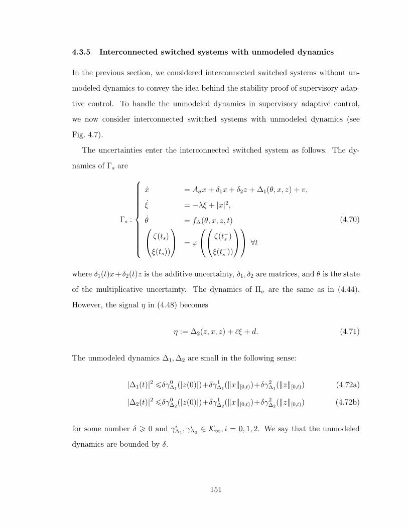
4.3.5 Interconnected switched systems with unmodeled dynamics
In the previous section, we considered interconnected switched systems without un-
modeled dynamics to convey the idea behind the stability proof of supervisory adap-
tive control. To handle the unmodeled dynamics in supervisory adaptive control,
we now consider interconnected switched systems with unmodeled dynamics (see
Fig. 4.7).
The uncertainties enter the interconnected switched system as follows. The dy-
namics of Γs are
Γs :
x = Aσx+ δ1x+ δ2z + ∆1(θ, x, z) + v,
ξ = −λξ + |x|2,θ = f∆(θ, x, z, t) ζ(ts)
ξ(ts))
= ϕ
ζ(t−s )
ξ(t−s ))
∀t
(4.70)
where δ1(t)x+ δ2(t)z is the additive uncertainty, δ1, δ2 are matrices, and θ is the state
of the multiplicative uncertainty. The dynamics of Πσ are the same as in (4.44).
However, the signal η in (4.48) becomes
η := ∆2(z, x, z) + cξ + d. (4.71)
The unmodeled dynamics ∆1,∆2 are small in the following sense:
|∆1(t)|2 6δγ0∆1
(|z(0)|)+δγ1∆1
(‖x‖[0,t))+δγ2∆1
(‖z‖[0,t)) (4.72a)
|∆2(t)|2 6δγ0∆2
(|z(0)|)+δγ1∆2
(‖x‖[0,t))+δγ2∆2
(‖z‖[0,t)) (4.72b)
for some number δ > 0 and γi∆1, γi
∆2∈ K∞, i = 0, 1, 2. We say that the unmodeled
dynamics are bounded by δ.
151

∆, δ1, δ2
Γs : (x, ξ)
Πσ : zu
σ
s
x
z
‖u‖22,λ 6 f(z, ξ, t) Nσ 6 f1(ξ) |x(ti)| 6 f2(|x(t
−
i )|, |z(t−i )|)ξ(ti) 6 f3(ξ(t
−
i ), |(z)0,t‖2,λ)
Figure 4.7: Interconnected switched systems with unmodeled dynamics
Compared to the interconnected system in Fig. 4.6, the configuration in Fig. 4.7
has the extra block ∆ and extra signals from ∆ coming into the function N0 and
f . The dash-dot box (Γs,Πσ) denotes the interconnected switched system without
unmodeled dynamics.
We assume that δ1(t) is small enough in the norm as follows. Since Ap are Hurwitz
for all p ∈ P, from linear system theory, there always exists a δ > 0 such that for all
‖δ1‖[0,∞) 6 δ and for all p ∈ P, the system x = (Ap+δ1(t))x is uniformly exponentially
stable i.e., |x(t)|2 6 ce−λ(t−t0)|x(t0)|2 ∀t > t0 for some c, λ > 0. Denote by δmax1 the
supremum of all such δ. Assume that ‖δ1‖[0,∞) 6 δ1 for some 0 < δ1 6 δmax1 .
The lemmas below are the extensions of corresponding lemmas for the case without
unmodeled dynamics in the previous section.
Lemma 4.6 For every λ < λ, for all t > 0,
|x(t)|2 6 a0(c1|x(t−s )|2+c2|z(ts)|2)e−λ(t−ts) + γ0δ2‖(z)ts,t‖22,λ
+ γ1‖(∆1)ts,t‖22,λ+ γ2‖(v)ts,t‖22,λ
(4.73)
ξ(t) 6 f1(ts)e−λ(t−ts) + γ0
λ−λ‖(z)ts,t‖22,λ+ γ1
λ−λ‖(∆1)ts,t‖22,λ+ γ2
λ−λ‖(v)ts,t‖22,λ
(4.74)
where f1(ts) := c1a0ξ(t−s ) + c2a0‖(z)0,ts‖22,λ + c1a0
λ−λ|x(t−s )|2 + c2a0
λ−λ|z(ts)|2 for some con-
152

stants a0, γ0, γ1, γ2 > 0 and δ2 := ‖δ2‖[0,∞).
Proof Since s is constant in [ts, t), we have
|x(t)|2 6 a0e−λ(t−ts)|x(ts)|2 + γ0δ2‖(z)ts,t‖22,λ
+ γ1‖(∆1)ts,t‖22,λ+ γ2‖(v)ts,t‖22,λ
for some a0, γ0, γ1, γ2 > 0. Using (4.45a), we then have (4.73). Taking eλt-weighted
L2 norm of (4.73), in view of (1.11) and (1.12), we get
‖(|x|)ts,t‖22,λ 6 (c1|x(t−s )|2 + c2|z(ts)|2)a0
λ− λe−λ(t−ts)
+γ0δ2
λ− λ‖(z)ts ,t‖22,λ +
γ1
λ− λ‖(∆1)ts,t‖22,λ +
γ2
λ− λ‖(v)ts,t‖22,λ.
Combining the foregoing inequality with (4.45a) and the fact that ξ(t) = ξ(ts)e−λ(t−ts)+
‖(v2)ts,t‖22λ, we get (4.74).
Lemma 4.7 For every λ < λ0
κ+1, α ∈ (0, 1),
|z(t)|2 6 gα(t)e−λ(t−ts) + γ3νκ+1(t) (4.75)
‖(z)0,t‖22,λ 6 ‖(z)0,ts‖22,λe−λ(t−ts) +
gα(t)
λ− λe−λ(t−ts) + γ3‖(ν
κ+12 )ts,t‖22,λ, ∀t > 0 (4.76)
where ν(t) := d+ |∆2(t)|+ cγ0δ2λ−λ‖(z)ts,t‖22,λ + cγ1
λ−λ‖(∆1)ts,t‖22,λ + cγ2
λ−λ‖(v)ts,t‖22,λ, gα(t) :=
(γ1α1−κcκfκ
1 (ts) + γ1(1 − α)1−κ‖ν‖κ[ts,t])|z(ts)|2 + γ2α−κcκ+1fκ+1
1 (ts) and f1 is as in
Lemma 4.6, and λ := minλ0 − λκ, (κ+ 1)λ.
Proof From the definition of η in (4.71) and (4.74), we have
η(t) 6 d+ |∆2(t)|+ cf1(ts)e−λ(t−ts)
+ cγ1
λ−λ‖(∆1)ts,t‖22,λ+ cγ2
λ−λ‖(v)ts,t‖22,λ.
(4.77)
For the convex function ar, r > 1 and any number α ∈ (0, 1), we have (a + b)r =
(αa/α + (1 − α)b/(1 − α))r 6 α1−rar + (1 − α)1−rbr ∀a, b > 0. Pick an α ∈ (0, 1),
153

using the foregoing inequality, for all τ ∈ [ts, t), for all r > 1, we have
ηr(τ) 6 α1−rcrf r1 (ts)e
−rλ(τ−ts) + (1− α)1−rνr(τ), (4.78)
in view of the definition of ν as in the lemma. Using (4.78) with r = κ and r = κ+ 1
subsequently, from (4.77), (4.78), and (4.53), we get
|z(t)|2 6 γ1α1−κcκfκ
1 (ts)e−λ0(t−ts)|z(ts)|2
+ γ1(1− α)1−κνκ(t)e−(λ0−λκ)(t−ts)|z(ts)|2
+ γ2α−κcκ+1fκ+1
1 (ts)e−(κ+1)λ(t−ts)
+ γ2(1−α)−κνκ+1(t).
The foregoing inequality leads to (4.75) in view of the definition of g and the fact
ν(τ) 6 ‖ν‖[ts,t] ∀τ ∈ [ts, t). Taking eλt-weighted L2 norm of (4.75), we get ‖(z)ts,t‖22,λ 6
g(x,ξ,z,ν,t)
λ−λe−λ(t−ts) + γ3‖(ν
κ+12 )ts,t‖22λ where γ3 := γ22
κ. The foregoing inequality and
the fact that ‖(z)0,t‖22λ 6 ‖(z)0,ts‖22,λe−λ(t−ts) + ‖(z)ts,t‖22,λ leads to (4.76).
Let
W(t):=c1a0ξ(t)+c2a0‖(z)0,t‖22,λ+c1a0
λ−λ|x(t)|2+c2a0
λ−λ|z(t)|2. (4.79)
Lemma 4.8 Suppose that |v(t)| 6 v, cγ0δ2λ−λ‖(z)ts ,t‖22,λ 6 δz ∀t > 0, |∆1(t)| 6 ∆1, and
|∆2(t)| 6 ∆2 ∀t ∈ [0, T ) for some T > 0. Suppose that 0 < λ < minλ, λ, λ∆. We
have
W (t) 6 (α1Wκ(t−s )+α2)W (t−s )e−λ(t−ts) + α3 ∀t ∈ [0, T ), (4.80)
154

where
α1 :=c2a0
λ− λγ4 +c2a0
λ− λγ4 (4.81a)
α2 := 2c1a0 + γ12κ−1νκ + γ12
κ−1νκ λ− λλ− λ (4.81b)
α3 :=c1a0
λ− λγv2
λ+
c2a0
λ− λγ3ν
κ+1 +c1a0γ2v
2
(λ− λ)λ+c2a0γ3ν
κ+1
λ+
c1a0
λ− λγ1δ1 +
c1a0γ1
(λ− λ)λδ1
(4.81c)
ν := d+ δz + ∆2 +cγ1
(λ− λ)λ∆1 +
cγ2
λ− λv2. (4.81d)
Proof In view of ν as in Lemma 4.7 and the lemma hypothesis, we have |ν(t)| 6 ν.
Notice that W (t−s ) = f1(ts) and |z(ts)|2 6 λ−λc2a0
W (t−s ) from (4.79). We then have
gα(t) 6 γ1α1−κcκ λ−λ
c2a0W κ+1(t−s ) + γ1(1− α)1−κνκ|z(ts)|2
+ γ2α−κcκ+1W κ+1(t−s )
=: γ4Wκ+1(t−s ) + γ5|z(ts)|2, (4.82)
where γ4 := γ1α1−κcκ λ−λ
c2a0+ γ2α
−κcκ+1 and γ5 := γ1(1 − α)1−κνκ. From (4.75) and
(4.82), we get
|z(t)|2 6 (γ4Wκ+1(t−s )+γ5|z(ts)|2)e−λ(t−ts)+γ3ν
κ+1, (4.83)
‖(z)ts,t‖22,λ 6 1λ−λ
(γ4Wκ+1(t−s )+γ5|z(ts)|2)e−λ(t−ts)
+γ3
λνκ+1. (4.84)
From (4.76) and (4.82), we have
‖(z)0,t‖22,λ 6 (‖(z)0,ts‖22,λ +γ5
λ− λ |z(ts)|2)e−λ(t−ts)
+γ4
λ− λWκ+1(t−s )e−λ(t−ts) +
γ3νκ+1
λ. (4.85)
155

From (4.73), we get
|x(t)|2 6 a0(c1|x(t−s )|2+c2|z(ts)|2)e−λ(t−ts)
+ γ0δ2γ5
λ−λ|z(ts)|2e−λ(t−ts)+ γ0δ2γ4
λ−λW κ+1(t−s )e−λ(t−ts)
+ γ0δ2γ3
(λ−λ)λνκ+1 + γ1∆1+
γ2
λv2.
(4.86)
From (4.74), we get
ξ(t) 6 W (t−s )e−λ(t−ts) + γ0δ2γ5
(λ−λ)(λ−λ)|z(ts)|2e−λ(t−ts)
+ γ0δ2γ4
(λ−λ)(λ−λ)W κ+1(t−s )e−λ(t−ts)
+γ0δ2γ3
(λ− λ)λνκ+1 +
γ1∆1
(λ− λ)λ+
γ2v2
(λ− λ)λ. (4.87)
From (4.83), (4.85), and (4.87), in view of (4.79), we have
W (t) 6 c1a0W (t−s )e−λ(t−ts) + c5Wκ+1(t−s )e−λ(t−ts) + c7
+ (c6|z(ts)|2+ c21a20
λ−λ|x(t−s )|2 + c2a0‖(z)0,ts‖22,λ)e
−λ(t−ts), (4.88)
where c5 := c1a0γ0δ2γ4
(λ−λ)(λ−λ)+ c2a0γ4
λ−λ+ c2a0
λ−λγ4, c6 := c1a0γ0δ2γ5
(λ−λ)(λ−λ)+ c2a0γ5
λ−λ+ c2a0
λ−λγ5 + (c2a0 +
γ0δ2γ5
λ−λ) c1a0
λ−λ, and c7 := c1a0
λ−λγ1δ1 + c1a0
λ−λ
γv2
λ+ c2a0
λ−λγ3ν
κ+1 + c1a0γ1δ1(λ−λ)λ
+ c1a0γ2v2
(λ−λ)λ+ c2a0γ3νκ+1
λ.
Let c8 := maxc6 λ−λc2a0γ
, c1a0, 1 = c6λ−λc2a0
. Then from (4.88), we get
W (t) 6 c1W (t−s )e−λ(t−ts) + c5Wκ+1(t−s )e−λ(t−ts)
+ c8W (t−s )e−λ(t−ts) + c7.
We then have (4.80) where α1 := c5, α2 := c1 + c8, and α3 := c7.
The following result quantifies the robustness property of a class of switching sig-
nals S in the following sense: every s ∈ S implies stability of the interconnected
switched system without unmodeled dynamics and the same switching signal still
guarantees stability in the presence of unmodeled dynamics provided that the un-
156

modeled dynamics are small enough. The set S depends on the bound of the initial
state and the bound on the unmodeled dynamics also depends on the bound of the
initial state of the interconnected switched system.
Let a = ∆1 and b = δz + ∆2 in (4.81d) and define the functions α2(a, b) := α2
and α3(a, b) := α3 with α2 as in (4.81b) and α3 as in (4.81c). Let ρa,b(M) :=
α1Mκ + α2(a, b) where κ is the constant as in Lemma 4.8 and α1 is as in (4.81a). Let
Wa,b(X0, Z0) := ρa,b(c1a0
λ−λX0 + c2a0
λ−λZ0)(
c1a0
λ−λX0 + c2a0
λ−λZ0) for some X0, Z0 > 0. Recall
that δ is the bound on the unmodeled dynamics of θ as in (4.72) and δ1, δ2 are the
bounds on L∞-norm of δ1(t) and δ2(t), respectively.
Theorem 4.4 Consider the interconnected switched system described in Section 4.3.5.
Let δa, δb, X0, Z0 > 0. Then for every E > 0, there exists a number δ > 0 such that if
maxδ, δ1, δ2 6 δ and |θ(0)| < E, then we have
max|x(t)|2, |z(t)|2 6 γ1(Wδa,δb(X0, Z0))e
−λ + γ2(α3(δa, δb)) ∀t (4.89)
for all |x(0)|2 6 X0, |z(0)|2 6 Z0 and every s not faster than αρ,W0,δd,N where αρ,W0,δd,N
is as in (3.74) for some γ1, γ2 ∈ K∞ and δd > 0, N > 1.
Proof Let T = supt : |∆1(t)| 6 ∆1, |∆2(t)| 6 ∆2,cγ0δ2λ−λ‖(z)ts,t‖22,λ 6 δ2. Then ap-
plying Lemma 3.2 using W as in (4.80), we have that W (t) 6 γ1(Wδa,δb(X0, Z0))e
−λt+
γ2(α3) ∀t ∈ [0, T ) for some γ1, γ2 ∈ K∞. Let W := γ1(Wδa,δb(X0, Z0)) + γ2(α3).
From the definition of W (t), we then have |x(t)|2 6 λ−λc1a0
W , |z(t)|2 6 λ−λc2a0
W . In
view of (4.72a), (4.72b), and the definition of δz, if δ 6 min(γ0∆1
(E) + γ1∆1
( λ−λc1a0
W ) +
γ2∆1
( λ−λc2a0
W ))−1δa, (γ0∆2
(E)+γ1∆2
( λ−λc1a0
W )+γ2∆2
( λ−λc2a0
W ))−1δb/2,δb
2c2a0
Wcγ0, δmax
1 =: δ, then
δ1 6 δ 6 δmax1 , |∆1(t)| 6 δa, |∆2(t)| + cγ0δ2
λ−λ‖(z)ts ,t‖22,λ 6 δb ∀t ∈ [0, T ). From the
definition of T , we conclude that T = ∞. Thus, if the unmodeled dynamics are
bounded by δ and the initial state of the unmodeled dynamic is bounded by E, then
W (t) 6 W ∀t > 0. It follows that all the states are bounded. We then have (4.95)
with γ1 := c0γ1, γ2 := c0γ2 where c0 := max λ−λc1a0
, λ−λc2a0.
157

4.3.6 Stability of the closed-loop control system
We say that the unmodeled dynamics of z are bounded by δ∆ if (it has bounded
input/output-to-state gain):
|g∆(z, x, u, t)|2 6δ∆γ0g(|z(0)|)e−λ∆t+δ∆γ
1g(‖x‖[0,t))+δ∆γ
2g (‖u‖[0,t)) (4.90a)
|h∆(z, x, u, t)|2 6δ∆γ0h(|z(0)|)e−λ∆t+δ∆γ
1h(‖x‖[0,t))+δ∆γ
2h(‖u‖[0,t)) (4.90b)
for some numbers δ∆, λ∆ > 0 and functions γig, γ
ih ∈ K∞, i = 0, 1, 2. Define
δP := max‖δA(t)‖[0,∞), ‖δB(t)‖[0,∞), ‖δC(t)‖[0,∞) + supp,q∈P
‖Cp − Cq‖. (4.91)
Theorem 4.5 Consider the supervisory adaptive control scheme described in Section
4.3.1. For every M, v, w > 0, there exist an event profile α and a number δ > 0 such
that if δP 6 δ, ‖v‖∞ 6 v, and ‖w‖∞ 6 w, for all unmodeled dynamics such that
maxδ∆, δP 6 δ and all the initial states |(x(0), z(0))| < M , all the closed-loop
signals are bounded and
|x(t)|2 6 γ(max|x(0)|, |z(0)|)e−λt + α ∀t > 0
for some γ ∈ K∞ and α > 0 for every switching signal s not faster than α. Further,
for every εx > 0, we can make |x(t)| < εx ∀t > T for a large enough T if v, w, and δ
are small enough.
Proof Bounds of the unmodeled dynamics
Note that u = Kσ(t)xσ(t) so |u(t)| 6 c|xCE(t)| = c|z(t)| and ‖u‖[0,t) 6 c‖z‖[0,t)
for some c > 0. Also, x = xs(t) + xs(t), so |x(t)| 6 |xs(t)(t)| + |xs(t)(t)| and ‖x‖[0,t) 6
‖ζ‖[0,t)+a‖z‖[0,t) for some constant a > 0. From (4.90a), using the separation property
of class K∞ functions (that for every γ ∈ K∞, ∃γ1, γ2 ∈ K∞ : γ(r + t) 6 γ1(r) +
158

γ2(t) ∀r, t), we have
|∆1(t)|2 = |g∆(z, x, u, t)|2 6δgγ0g (|z(0)|)e−λ∆t+δgγ
1g (‖ζ‖[0,t))+δgγ
2g (‖z‖[0,t)) (4.92)
for some γ1, γ2 ∈ K∞ and δg > 0 such that δg → 0 as δ∆ → 0. If λ∆ > λ, taking
eλt-weighted L2 of both sides of (4.90b) and using the separation property of class
K∞ functions, we have
‖(h∆(z, x, u, τ))0,t‖22,λ 6 δhγ0h(|z(0)|) e−λt
λ∆ − λ+δh
1
λγ1
h(‖ζ‖[0,t))+δh1
λγ2
h(‖z‖[0,t))
for some γ1∆2, γ2
∆2∈ K∞ and δh > 0 such that δh → 0 as δ∆ → 0. The foregoing
inequality and the definition of ∆2 as in (4.38e) yield
|∆2(t)|2 6 γc11
λ‖z‖2[0,t) + δhγ
0h(|z(0)|)+δh
1
λγ1
h(‖ζ‖[0,t))+δh1
λγ2
h(‖z‖[0,t)). (4.93)
We rewrite (4.92) and (4.93) into the forms as in (4.72):
|∆1(t)|2 6 δγ0∆1
(|z(0)|)+δγ1∆1
(‖ζ‖[0,t))+δγ2∆1
(‖xCE‖[0,t)), (4.94a)
|∆2(t)|2 6 δγ0∆2
(|z(0)|)+δγ1∆2
(‖ζ‖[0,t))+δγ2∆2
(‖xCE‖[0,t)) (4.94b)
for some γj∆i∈ K∞, i = 1, 2, j = 0, 1, 2 and δ > 0 such that δ → 0 if δ∆ → 0 and
c1 → 0.
Stability
The equations (4.32a), (4.33), (4.34a), (4.34b), (4.36), and (4.37) describe an inter-
connected switched system and the equation z = f∆(z, x, u, t) = f∆(z, ζ, z, t) (noting
that x(t) = z(t) + xs(t)(t) ∀t and u = Kσ(t)xσ(t)) and the inequality (4.94) describes
the unmodeled dynamics for the interconnected switched system as in the framework
presented in Section 4.3.5.
From the definition of δP as in (4.91), c1 → 0 if δP → 0 where c1 is as in (4.38).
Hence, δ → 0 if maxδ∆, δP → 0 where δ is as in (4.94). We also have that
159

δ1 → 0, δ2 → 0 if δP → 0. Thus, for every δ0 > 0, there exists δ > 0 such that if
maxδ∆, δP 6 δ, then maxδ1, δ2, δ 6 δ0.
The stability result for interconnected switched systems in Theorem 4.4 states
that for every δa, δb,X0, Z0, E > 0, there exists a number δ0 > 0 such that if
maxδ1, δ2, δ 6 δ0 and |z(0)| < E, then all the closed-loop signals are bounded
and
max|xs(t)(t)|2, |xCE(t)|2 6 γ1(Wδa,δb(|xs(0)(0)|, |xCE(0)|))e−λ + γ2(α3) ∀t (4.95)
for all |xs(t)(0)|2 6 X0, |xCE(0)|2 6 Z0 and every s not faster than the profile αρ,W0,δd,N
for some γ1, γ2 ∈ K∞. Let M := min√
2X20 + 2Z2
0 , E, γ(r) := γ1(Wδa,δb(r, r)), and
α = γ2(α3). Since γ1 ∈ K∞, we have γ ∈ K∞. Using |x(t)|2 6 2(|xs(t)(t)|2+ |xCE(t)|2),it follows that
|x(t)|2 6 γ(max|x(0)|, |z(0)|)e−λt + α ∀t > 0 (4.96)
for some γ ∈ K∞ if all the initial state is bounded by M .
No unmodeled dynamics, no disturbances, and no noise
Consider the case where there are no unmodeled dynamics, disturbances, and
noise, i.e., v = 0, w = 0, δ1 = δ2 = δ = 0. The constants α1, α2, α3 depends on ε as
follows. For notational brevity, we write a ≈ b if a = kb for some constant k that does
not depend on b. From (4.38) and (4.48), we have c3 = m− c4 ln ε, c4 = m/ ln(1+h),
and so γ0 = µc3 = µmε−c4 lnµ = µmε−κ, i.e., γ0 ≈ ε−κ. From the definitions of γ1, γ2
as in the proof of Lemma 4.3, γ1, γ2 ≈ γ0, and hence, γ1, γ2 ≈ ε−κ. It follows that
γ3 ≈ εκ. From the definition of ν in (4.63d) and (4.48), we have ν = d = ε. Then
νκ+1 ≈ εκ+1, and so γ3νκ+1 ≈ ε. From (4.63c), with v = 0, we get α3 ≈ ε which
means α3 → 0 as ε → 0. Equation (4.69) implies that there exists T > 0 such
that |x(t)|2, |z(t)|2 6 γ2(α3) + ǫ ∀t > T for a large enough T . Thus, we can get
|x(t)| be as small as desired by reducing ε close to 0. One possible way of reducing ε
160

is as follows. Choose ε(0) = ε0 small enough so that γ2(ε0) < minX0, Z02/4. Let
T0 := ln minX0,Z02/4−γ2(ε0)γ(M)
. Then |x(t)| 6 minX0, Z0/2 for all t > T0 in view of (??)
and (4.96). Choose ε1 < ε0 such that γ2(ε1) < minX0, Z02/16. At the time T0, set
ε to this value ε1. Note that α1(T0) ≈ γ1(T0), γ2(T0) ≈ ε−κ1 but W (T0) ≈ γ2(ε0) ≈ ε
(from the definition of γ2 as in the proof of Lemma 3.2 and γ2 = c0γ2), and so, we
have α1Wκ(T0) + α2 6 W . The equation (4.96) is also applicable starting from the
time T0 so if we let T1 := ln minX0,Z02/16−γ2(ε1)γ(M)
, then |x(t)| 6 minX0, Z0/4 for all
t > T0 + T1. Repeating the procedure, at step k, we have |x(t)| 6 minX0, Z0/2k
for all t > T0 + · · ·+ Tk−1. As k →∞, |x(t)| → 0.
Small boundedness for small unmodeled dynamics, disturbances, and noise
Denote by ν and α3 the values of ν and α3 in the case without unmodeled dynamics,
disturbances, and noise. In the case with unmodeled dynamics, disturbances, and
noise, we have d := ε+ 4γλw2 and hence, ν := ε+ 4γ
λw2 + δz + ∆2 + cγ1
(λ−λ)λ∆1 + cγ2
λ−λv2
in view of (4.81d). Sine δz → 0 as δ2 → 0, ∆1 → 0 as δ → 0, and ∆2 → 0 as
δ, δP → 0, we have ν → ν as v, w, δ2, δ, δP → 0. Also, from (4.81c), α3 → α3 as
v → 0 and δ1 → 0. Thus, we can asymptotically recover the case without unmodeled
dynamics, disturbances, and noise as v, w, δ2, δ, δP → 0, which means we can make
|x(t)| be as small as desired for all t > T for some large enough T if v, w, δ2, δ, and
δP are small enough.
4.3.7 Example
Example 4.3 Consider the following uncertain system:
x =
0 1
a1(t) a2(t)
x+
0
b(t)
u
y =[1 0
]x,
161

where a1(t), a2(t), and b(t) are unknown (this system with known constant b(t),
a1 = −2 sin(t), a2 = 6 is termed a “fast” system in example 7.26 in [85]). We know
the uncertainty set Ω which these parameters belong to, (a1(t), a2(t), b(t)) ∈ Ω =:
[−5, 5] × [−10, 10] × [−3, 3]. We design a supervisory adaptive controller for the
plant as outlined in Section 4.3.1, using the nominal values −4,−2, 2, 4 for a1(t),
−8,−4, 4, 8 for a2(t), and −2, 2 for b(t). Controllers place closed-loop poles at
−10,−5 and observer poles at −30,−20. The design constants are h = 0.01,λ =
0.4,ǫ = 10−6, γ = 104.
We simulate the supervisory adaptive control in the presence of unmodeled dy-
namics z, disturbances w, and noises v as follows:
x =
0 1
a1(t) a2(t)
x+
0
b(t)
u+ 0.01z + 0.01u+ w
y =[1 0
]x+ v
z = −0.8z + u,
where a1(t) = 1 + 2 sin(4t), a2(t) = −6, b(t) = (1 + 0.5 sin(2t)) cos(0.5t), w uniformly
randomly distributed between [−0.1, 0.1], and v uniformly randomly distributed be-
tween [−0.5, 0.5]. The result is plotted in Fig. 4.8. This control problem is challenging
for other adaptive control schemes due to the presence of unmodeled dynamics, dis-
turbances, and noises but especially because the sign of b(t) is not known. However,
Fig. 4.8 shows that the closed-loop states are bounded and close to zero except when
there are abrupt changes in the parameter b.
4.4 Model Reference Supervisory Adaptive Control
Our results on stability of interconnected switched systems can also be applied to
the output tracking problem for uncertain time-varying SISO systems. We describe
162

0 5 10 15 20 25 30 35 40 45 50−5
0
5
x
1
x2
0 5 10 15 20 25 30 35 40 45 50−100
−50
0
50
100
u
0 5 10 15 20 25 30 35 40 45 500
10
20
30
40
t
σ
Figure 4.8: supervisory adaptive stabilization
here a supervisory model reference adaptive control (SMRAC) scheme for uncertain
time-varying SISO plants. While much research has applied supervisory adaptive
control to stabilization and set-point tracking problems, supervisory adaptive control
has not been applied to model reference output tracking. We provide here details of
this application of supervisory adaptive control.
4.4.1 Model reference controller for a known LTI plant
We describe how to construct a particular model reference controller (MRC) for a
LTI SISO system (see [80]). Consider a plant in transfer function form
y
u= g
∑n−mi=0 bis
i
∑ni=0 aisi
=: gb(s)
a(s), (4.97)
163

where bn−m = an = 1. For an integer r, define 1r := [1 0 . . . 0]T ∈ Rr and 1r :=
[0 . . . 0 1]T ∈ Rr. Let
a(s)
b(s)= β(s)− α(s)
b(s), (4.98)
where α(s) =∑n−m−1
i=0 αisi and β(s) =
∑mi=0 βis
i, βm = 1. We construct the following
state-space realization of (4.97):
w
v
=
A1 1n−m1T
m
1mα A2
w
v
+
0
g1m
u
y =[0 1T
m
]w
v
(4.99)
where A1 =
0 1 0. . .
1
−b0 −b1 . . . −bn−m−1
, A2 =
0 1 0. . .
1
−β0 −β1 . . . −βm−1
, and α =
[α0 . . . αn−m−1].
We want the output y to track the output of a reference model
xm = Amxm +Bmum, xm(0) = x0m
ym = Cmxm
(4.100)
where xm ∈ Rnm , nm > m. Let Pm(s) = Cm(sI − Am)−1Bm. Let q(s) =∑m
i=0 qisi,
qm = 1, be an m-order polynomial that has all roots in the left-half complex plane.
Since nm > m, there exist k1 ∈ R1×nm and k2 ∈ R such that
Pm(s)
1Tm(sI − A2)−11m
= k2 + k1(sI −Am)−1Bm, (4.101)
164

where A2 =
0 1 0. . .
1
−q0 −q1 . . . −qm−1
. A tracking controller is given by
u =1
g(−αw + (q − β)v + k1xm + k2um) (4.102)
where q = [−q0 . . . − qm−1] and β = [−β0 . . . − βm−1].
4.4.2 Supervisory adaptive tracking
Consider an uncertain time-varying plant described in the linear time-varying (LTV)
differential equation model
y
u= g(t)
∑n−mi=0 bi(t)s
i
∑ni=0 ai(t)si
=: gb(s, t)
a(s, t), (4.103)
where some (or all) of the coefficients ai(t), bi(t) are not known. We group all unknown
coefficients into a vector ν(t) (also called the unknown parameter). We know the
uncertainty set Ω to which the unknown parameter belongs. The uncertain plant
(4.103) with model uncertainty is
y
u=
(gb(s, t)
a(s, t)+ ∆1
)(1 + ∆2), (4.104)
where ∆1,∆2 are unmodeled dynamics.
As before, we partition the uncertainty set into m nonoverlapping subsets and for
each subset, pick a nominal value νi, i ∈ P = 1, . . . ,m. Using the realization as in
the previous section, the state space representation for each model with a parameter
165

νp, p ∈ P is
x = Apx+Bpu (4.105)
y = Cx (4.106)
where x = (w, v), Ap =
A1,p 1n−m1T
m
1mα A2,p
, Bp :=
0
gp1m
, C = [0 1T
m], and
A1,p, A2,p, gp are the constants defined as in (4.99) for the system with parameter
νp.
The multiestimator is still exactly the same as in (4.20). The multicontroller is
up =1
gp(Kpxp + k1xm + k2um), (4.107)
where Kp = [−αp (q − βp)].
Analysis
The injected system with controller p is
xCE = ApxCE + Bp(k1xm + k2um) + Byp, (4.108)
where xCE = (x1, . . . , xm), Ap =
A1 + L1C . . . 1gpB1Kp − LpC . . . 0
0 Ap + 1gpBpKp . . . 0
0 1gpBmKp − LpC . . . Am + LmC
,
Bp := 1gp
B1
...
Bm
, B :=
L1
...
Lm
and y = y − Cxp. The matrix Ap are Hurwitz for all
p ∈ P.
Let ξ be the solution of the switched system with the switching signal σ and the
166

subsystems
ξ = Apξ + Bp(k1xm + k2um) (4.109)
and ξ(0) = 0. Let epy = Cpξ − Cmxm where Cp := [01×(p−1)n C 01×(m−p)n]. We have
ξ
xm
=
Ap Bpk1
0 Am
ξ
xm
+
B
1pk2
Bm
um. (4.110)
By construction (due to the model matching procedure), the transfer function um 7→ep
y of (4.110) is zero for all um and for all p ∈ P. That means epy = [Cp Cm]ζ(t) for
all t > t0 where ζ is a state of the switched system
ζ =
Ap Bpk1
0 Am
ζ =: Apζ. (4.111)
The matrix Ap are Hurwitz for all p ∈ P.
Consider the switched injected system and let xCE = xCE − ξ. From (4.108) and
(4.109), we have
˙xCE = xCE − ξ = Aσ(t)xCE + Byσ(t). (4.112)
Let e = y − ym be the output tracking error. Then e = Cxs(t) − Cmxm = C(xs(t) +
xs(t)(t))− Cmxm = Cxs(t)(t) + es(t)y .
The interconnected switched system that arises from the closed-loop control system
consists of the following switched systems:
1. The first switched system is the state error dynamics as in (4.30).
167

2. The second switched system is
z =
Aσ 0 0
0 Aσ Bσ
0 0 Am
z +
B
0
0
yσ, (4.113)
where z = (xCE, ζ).
Using the stability result in Section 4.3.5, we conclude that the model reference
supervisory adaptive control scheme can asymptotically drive output tracking error to
zero when there is no disturbance, provided that the plant varies slowly enough. In the
presence of disturbance and unmodeled dynamics, we can still guarantee boundedness
of all the closed-loop states if the disturbances and the unmodeled dynamics are small
enough.
Theorem 4.6 Consider the time-varying uncertain system (4.103). Design a model
reference supervisory adaptive control scheme as in Section 4.4.2. Suppose that the
initial state is bounded by X0. Let s be the approximate switching signal for the time-
varying plant and δ be the approximation error. There exist an average dwell-time
vs. chatter bound curve φδ,X0, and an average dwell-time vs. dwell-time curve ψδ,X0
such that for every switching signal s having a dwell-time δd, a chatter bound N , and
an average dwell-time τ such that τ > φδ,X0(N) and τ > ψδ,X0(δd), the tracking error
asymptotically goes to zero. In the presence of disturbances and unmodeled dynamics,
all the closed-loop states can be kept bounded if the disturbances and the unmodeled
dynamics are small enough.
168

4.4.3 Example
Example 4.4 The following model reference adaptive control problem is from [80].
Consider the time-varying uncertain plant
x = a(t)x+ g(t)u,
y = x,(4.114)
where (a(t), g(t)) belongs to the uncertainty set [−1, 1]× ([−2,−1]∪ [1, 2]). We want
to design a controller to track the output of the reference model Pm = 1s+1
. As noted
in [80], the fact that g(t) can be either positive or negative makes the adaptive control
problem challenging for adaptive control techniques that rely on the knowledge of the
sign of g(t).
We chose the nominal values of a(t) being −0.7,−0.3, 0.3, 0.7 and the nominal
values of g(t) being −1.5, 1.5. A multiestimator is
˙xp = apxp + gpu+ (−ap − 500)(xp − y) (4.115)
where p is an index, p ∈ 1, . . . , 8 (each p corresponding to a pair of nominal values
of a(t) and g(t)). For every p, a tracking controller is designed using the procedure
in [80]:
up =1
gp
((−100− ap)xp + xm + um), (4.116)
where xm is the state and um is the input of the reference model. The simulation result
is plotted in Fig. 4.9 for g(t) = (1.2+0.2 cos(3u/4))sgn(cos(u/4)) and a(t) = cos(u/3).
We add the sinusoidal noise 0.1 sin(10t) between 40 s and 60 s and a uniformly
distributed random noise between −0.05 and 0.05 from 60 s to 80 s. As we can see,
the control plant tracks the reference output very well. Note that the performance of
the adaptive control scheme in [80] would be affected in the presence of random noise
169

(see [80, Remark 6]) whereas, here, our control scheme still performs well in that
situation. On the other hand, the scheme in [80] can handle faster variation than the
supervisory control scheme here and [80] will also likely give a smaller control input.
0 10 20 30 40 50 60 70 80−2
−1
0
1
2
ab
0 10 20 30 40 50 60 70 80
−1
−0.5
0
0.5
1
y
m
y
0 10 20 30 40 50 60 70 800
2
4
6
8
t
σ
Figure 4.9: Model reference supervisory adaptive control
170
CHAPTER 5
CONCLUSIONS AND FUTURE WORK
In this dissertation, we formulated a new problem, namely, the invertibility problem
for switched systems. This problem seeks a condition on a switched system that
guarantees unique reconstruction of the switching signal and the input from an out-
put and a given initial state. In solving the invertibility problem, we introduced the
concept of singular pairs, which is peculiar to switched systems and does not have
a counterpart in nonswitched systems. We presented a necessary and sufficient con-
dition for invertibility of continuous-time switched linear systems, which says that
the individual subsystems should be invertible and there should be no singular pairs
with respect to the output set. For switched systems, not necessarily invertible but
with invertible subsystems, we provided an algorithm that finds switching signals
and inputs that generate a given output with a given initial state. We illustrated our
results by detailed examples.
Another contribution of the dissertation was to provide stability results for switched
nonlinear systems. We introduced the concept of event profiles to characterize slow
switching signals, which is a nonlinear generalization of the concept of average dwell-
time (which are equivalent to uniform affine event profiles). Using event profiles,
we classified classes of switching signals that guarantee asymptotic stability of au-
tonomous switched nonlinear systems when all subsystems are globally asymptoti-
cally stable, even when one cannot find a constant switching gain among the family
of Lyapunov functions of the subsystems. For switched nonlinear systems with in-
puts, when a constant switching gain among the family of ISS-Lyapunov functions
of the subsystems exists, we showed that under switching signals with large enough
average dwell-time, a switched system is ISS, eλt-weighted ISS, and eλt-weighted iISS,
if the individual subsystems are ISS. When such a constant does not exist, we also
171

provided a slow switching condition in terms of event profiles that guarantee ISS of
switched nonlinear systems.
We applied our ISS results for switched nonlinear systems to the problem of adap-
tively controlling uncertain plants. For nonlinear uncertain plants in the presence
of disturbances, using the scale-independent hysteresis switching logic, we showed
that the states can be kept bounded for arbitrary initial conditions and bounded
disturbances, provided that the injected systems are ISS with respect to the estima-
tion errors and there is a constant switching gain among ISS-Lyapunov functions of
the injected systems. We illustrated our results on a plant where it might be dif-
ficult to apply traditional adaptive control tools. We relaxed the requirement of a
global µ and achieved local boundedness of the plant state in the presence of bounded
disturbances; a detailed example of this was also included. For linear time-varying
uncertain plants, in the presence of unmodeled dynamics, disturbances, and noise,
we showed that the state can be kept bounded provided that the plant varies slowly
enough. Further, if there are no unmodeled dynamics, no disturbances, and no noise,
the closed-loop state can be made arbitrarily small with appropriate fine-tuning in
the supervisory control scheme.
There are several avenues for future research on the topics presented in this disser-
tation. For the invertibility problem, further investigation of the invertibility issues
for discrete-time switched systems as well as a geometric approach for continuous-time
switched systems are needed. A geometric result for invertibility will shed more in-
sight into intrinsic properties (that are coordinate independent) and will complement
the matrix-oriented approach presented here. For nonswitched systems, invertibility
for one time domain implies invertibility for every domain and it is not clear if this is
the case for switched systems. The robust invertibility property where the initial con-
dition is not known requires further investigation. An interesting design question is
to design the matrices C so that the switched system is invertible. Another direction
is to extend the results to switched nonlinear systems. Singular pairs for switched
172

nonlinear systems, though conceptually similar, could have different properties from
the linear counterpart and need further investigation. In solving the invertibility
problem for switched nonlinear systems, the extension of the structure algorithm for
nonswitched nonlinear systems [39] or the geometric approach [86] may be useful.
For stability of switched nonlinear systems, other stability properties such as input-
output-to-state stability can also be studied using event profiles. One can also try to
find out how the stability results of switched nonlinear systems presented here can
be applied to particular applications where the existence of constant switching gains
is not guaranteed.
Supervisory control can be further studied to address performance issues such as
how to choose the design parameters to achieve certain types of optimality or to
improve transient response. Another potential direction is to address the issue of
fast-switching plants by finding the design parameters that yield the largest class
of hybrid dwell-time signals. Also of future research interest is the case of time-
varying plants but with constant unknown parameters, which falls between the case
of time-invariant plants with constant unknown parameters and the case of plants
with time-varying unknown parameters considered in this dissertation.
173

REFERENCES
[1] J. Lygeros, C. Tomlin, and S. Sastry, “Controllers for reachability specificationsfor hybrid systems,” Automatica, vol. 35, no. 3, pp. 349–370, 1999.
[2] E. R. Westervelt, J. W. Grizzle, and D. E. Koditschek, “Hybrid zero dynamics ofplanar biped walkers,” IEEE Trans. Automat. Control, vol. 48, no. 1, pp. 42–56,2003.
[3] R. Olfati-Saber and R. M. Murray, “Consensus problems in networks of agentswith switching topology and time-delays,” IEEE Trans. Automat. Control,vol. 49, pp. 1520–1533, 2004.
[4] W. J. Rugh and J. S. Shamma, “Research on gain scheduling,” Automatica,vol. 36, no. 10, pp. 1401–1425, 2000.
[5] J. P. Hespanha, D. Liberzon, and A. S. Morse, “Overcoming the limitations ofadaptive control by means of logic-based switching,” Systems and Control Lett.,vol. 49, no. 1, pp. 49–65, 2003.
[6] M. Heymann, F. Lin, G. Meyer, and S. Resmerita, “Analysis of zeno behaviorsin a class of hybrid systems,” Automatica, vol. 50, no. 3, pp. 376–383, 2005.
[7] C. D. Persis, R. D. Santis, and A. Morse, “Switched nonlinear systems withstate-dependent dwell-time switching logic,” Systems and Control Lett., vol. 50,no. 4, pp. 291–302, 2003.
[8] H. Khalil, Nonlinear Systems, 3rd ed. New Jersey: Prentice Hall, 2002.
[9] D. Liberzon, Switching in Systems and Control. Boston: Birkhauser, 2003.
[10] M. Oishi and C. Tomlin, “Switching in nonminimum phase systems: Applicationsto a VSTOL aircraft,” in Proc. American Control Conference, vol. 1, 2000, pp.487–491.
[11] A. Jadbabaie, J. Lin, and A. S. Morse, “Coordination of groups of mobile au-tonomous agents using nearest neighbor rules,” IEEE Trans. Automat. Control,vol. 48, no. 6, pp. 988–1001, 2003.
[12] H. G. Tanner, A. Jadbabaie, and G. J. Pappas, “Stable flocking of mobile agentspart I: Dynamic topology,” in Proc. 42nd IEEE Conf. on Decision and Control,vol. 2, 2003, pp. 2016–2021.
[13] J. P. Hespanha, S. Bohacek, K. Obraczka, and J. Lee, “Hybrid modeling of TCPcongestion control,” in Lecture Notes in Computer Science, M. D. D. Benedettoand A. Sangiovanni-Vincentelli, Eds. Berlin: Springer-Verlag, 2001, vol. 2034,pp. 291–304.
174

[14] S. Bohacek, J. P. Hespanha, J. Lee, and K. Obraczka, “Modeling data com-munication networks using hybrid systems,” IEEE/ACM Trans. on Networking,vol. 15, pp. 630–643, 2007.
[15] R. W. Brockett and M. D. Mesarovic, “The reproducibility of multivariable con-trol systems,” J. Math. Anal. Appl., vol. 11, pp. 548–563, 1965.
[16] L. M. Silverman, “Inversion of multivariable linear systems,” IEEE Trans. Au-tomat. Control, vol. 14, no. 3, pp. 270–276, 1969.
[17] M. K. Sain and J. L. Massey, “Invertibility of linear time-invariant dynamicalsystems,” IEEE Trans. Automat. Control, vol. 14, pp. 141–149, 1969.
[18] R. Vidal, A. Chiuso, and S. Soatto, “Observability and identification of jumplinear systems,” in Proc. 41st IEEE Conf. on Decision and Control, vol. 41,2002, pp. 3614–3619.
[19] R. Vidal, A. Chiuso, S. Soatto, and S. Sastry, “Observability of linear hybridsystems,” in Hybrid Systems: Computation and Control, ser. Lecture Notes inComputer Science. Berlin: Springer-Verlag, 2003, vol. 2623, pp. 526–539.
[20] A. S. Morse, “Supervisory control of families of linear set-point controllers, part1: Exact matching,” IEEE Trans. Automat. Control, vol. 41, no. 10, pp. 1413–1431, 1996.
[21] J. P. Hespanha and A. S. Morse, “Stability of switched systems with averagedwell-time,” in Proc. 38th IEEE Conf. on Decision and Control, 1999, pp. 2655–2660.
[22] J. P. Hespanha, “Uniform stability of switched linear systems: Extensions ofLaSalle’s invariance principle,” IEEE Trans. Automat. Control, vol. 49, no. 4,pp. 470–482, 2004.
[23] J. P. Hespanha and A. S. Morse, “Certainty equivalence implies detectability,”Systems and Control Lett., vol. 36, no. 2, pp. 1–13, 1999.
[24] J. P. Hespanha, D. Liberzon, and A. S. Morse, “Supervision of integral-input-to-state stabilizing controllers,” Automatica, vol. 38, no. 8, pp. 1327–1335, 2002.
[25] A. S. Morse, “Supervisory control of families of linear set-point controllers, part2: Robustness,” IEEE Trans. Automat. Control, vol. 42, no. 11, pp. 1500–1515,1997.
[26] B. D. O. Anderson, T. S. Brinsmead, F. D. Bruyne, J. P. Hespanha, D. Liberzon,and A. S. Morse, “Multiple model adaptive control, part 1: Finite controllercoverings,” Int. J. Robust Nonlinear Control, vol. 10, pp. 909–929, 2000.
[27] P. A. Ioannou and J. Sun, Robust Adaptive Control. New Jersey: Prentice Hall,1996.
[28] L. M. Silverman and H. J. Payne, “Input-output structure of linear systemswith application to the decoupling problem,” SIAM J. Control, vol. 9, no. 2, pp.199–233, 1971.
175

[29] A. S. Morse and W. M. Wonham, “Status of noninteracting control,” IEEETrans. Automat. Control, vol. 16, no. 6, pp. 568–581, 1971.
[30] P. J. Moylan, “Stable inversion of linear systems,” IEEE Trans. Automat. Con-trol, vol. 22, no. 1, pp. 74–78, 1977.
[31] E. De Santis, M. D. Di Benedetto, and G. Pola, “On observability and detectabil-ity of continuous-time linear switching systems,” in Proc. 42nd IEEE Conf. onDecision and Control, 2003, pp. 5777–5782.
[32] M. Babaali and G. J. Pappas, “Observability of switched linear systems in con-tinuous time,” in Hybrid Systems: Computation and Control, ser. Lecture Notesin Computer Science, vol. 3414. Berlin: Springer-Verlag, 2005, pp. 103–117.
[33] K. Huang, A. Wagner, and Y. Ma, “Identification of hybrid linear time-invariantsystems via subspace embedding and segmentation,” in Proc. 43rd IEEE Conf.on Decision and Control, vol. 3, 2004, pp. 3227–3234.
[34] W. M. Wonham, Linear Multivariable Control: A Geometric Approach, 3rd ed.New York: Springer, 1985.
[35] H. L. Trentelman, A. Stoorvogel, and M. Hautus, Control Theory for LinearSystems. New York: Springer-Verlag, 2001.
[36] A. S. Morse, “Output controllability and system synthesis,” SIAM J. Control,vol. 9, no. 2, pp. 143–148, 1971.
[37] A. B. Arehart and W. A. Wolovich, “Bumpless switching controllers,” in Proc.35th IEEE Conf. Decision and Control, vol. 2, 1996, pp. 1654–1655.
[38] S. Sundaram and C. N. Hadjicostis, “Designing stable inverters and state ob-servers for switched linear systems with unknown inputs,” in Proc. 45th IEEEConf. on Decision and Control, 2006, pp. 4105–4110.
[39] S. Singh, “A modified algorithm for invertibility in nonlinear systems,” IEEETrans. Automat. Control, vol. 26, no. 2, pp. 595–598, 1981.
[40] M. Khammash and H. El-Samad, “Systems biology: From physiology to generegulation,” IEEE Control System Magazine, pp. 62–76, August 2004.
[41] E. D. Sontag, “Molecular systems biology and control,” European J. of Control,vol. 11, pp. 1–40, 2005.
[42] J. Pomerening, E. D. Sontag, and J. E. Ferrell, “Building a cell cycle oscillator:Hysteresis and bistability in the activation of Cdc2,” Nature Cell Biology, vol. 5,no. 4, pp. 346–351, 2003.
[43] R. Alur, C. Belta, F. Ivancic, V. Kumar, M. Mintz, G. J. Pappas, H. Rubin, andJ. Schug, “Hybrid modeling and simulation of biomolecular networks,” in HybridSystems: Computation and Control, ser. Lecture Notes in Computer Science,2001, vol. 2034, pp. 19–32.
176

[44] V. Rodionov, J. Yi, A. Kashina, A. Oladipo, and S. Gross, “Switching betweenmicrotubule- and actin-based transport systems in melanophores is controlled bycAMP levels,” Current Biology, vol. 13, no. 21, pp. 1837–1847, 2003.
[45] N. H. El-Farra, A. Gani, and P. D. Christofides, “A switched system approach forthe analysis and control of mode transition in biological networks,” in AmericanControl Conference, 2005, pp. 3247–3252.
[46] R. Ghosh and C. Tomlin, “Lateral inhibition through delta-notch signaling: Apiecewise affine hybrid model,” Lecture Notes in Computer Science, vol. 2034,pp. 232–246, 2001.
[47] R. Ghosh and C. Tomlin, “Hybrid system models of biological cell network sig-naling and differentiation,” in 39th Annual Allerton Conference on Communica-tions, Control and Computing, October 2001, pp. 942–951.
[48] A. Beccuti, T. Geyer, and M. Morari, “A hybrid system approach to powersystems voltage control,” in Proc. 44th IEEE Conf. on Decision and Control,2005, pp. 6774–6779.
[49] G. Fourlas, K. Kyriakopoulos, and C. Vournas, “Hybrid systems modeling forpower systems,” IEEE Circuits Syst. Mag., pp. 16–23, August 2004.
[50] I. Hiskens and M. Pai, “Hybrid systems view of power system modelling,” in2000 IEEE International Symposium on Circuits and Systems, vol. 2, 2000, pp.228–231.
[51] E. D. Sontag and Y. Wang, “On characterizations of the input-to-state stabilityproperty,” Systems and Control Lett., vol. 24, pp. 351–359, 1995.
[52] E. D. Sontag, “Comments on integral variants of ISS,” Systems and Control Lett.,vol. 34, pp. 93–100, 1998.
[53] J. L. Mancilla-Aguilar and R. A. Garcia, “A converse Lyapunov theorem fornonlinear switched systems,” Systems and Control Lett., vol. 41, no. 1, pp. 67–71, 2000.
[54] J. L. Mancilla-Aguilar and R. A. Garcia, “On the existence of common Lyapunovtriples for ISS and iISS switched systems,” in Proc. 39th IEEE Conf. on Decisionand Control, 2000, pp. 3507–3512.
[55] L. Vu and D. Liberzon, “Common Lyapunov functions for families of commutingnonlinear systems,” Systems and Control Lett., vol. 55, pp. 8–16, 2005.
[56] A. A. Agrachev and D. Liberzon, “Lie-algebraic stability criteria for switchedsystems,” SIAM J. Control Optim., vol. 40, pp. 253–269, 2001.
[57] L. Vu, D. Chatterjee, and D. Liberzon, “Input-to-state stability of switchedsystems and switching adaptive control,” Automatica, vol. 43, no. 4, pp. 639–646, 2007.
[58] W. Xie, C. Wen, and Z. Li, “Input-to-state stabilization of switched nonlinearsystems,” IEEE Trans. Automat. Control, vol. 46, no. 7, pp. 1111–1116, 2001.
177

[59] D. Liberzon, “ISS and integral-ISS disturbance attenuation with bounded con-trols,” in Proc. 38th IEEE Conf. on Decision and Control, 1999, pp. 2501–2506.
[60] J. P. Hespanha, D. Liberzon, and A. S. Morse, “Bounds on the number of switch-ings with scale-independent hysteresis: Applications to supervisory control,” inProc. 39th IEEE Conf. on Decision and Control, vol. 4, 2000, pp. 3622–3627.
[61] L. Praly and Y. Wang, “Stabilization in spite of matched unmodeled dynamicsand an equivalent definition of input to state stability,” Mathematics of Control,Signals and Systems, vol. 9, pp. 1–33, 1996.
[62] G. Zhai and A. N. Michel, “On practical stability of switched systems,” in Proc.41st IEEE Conf. on Decision and Control, vol. 3, 2002, pp. 3488–3493.
[63] X. Xu and G. Zhai, “Practical stability and stabilization of hybrid and switchedsystems,” IEEE Trans. Automat. Control, vol. 50, no. 11, pp. 1897–1903, 2005.
[64] E. D. Sontag, “Smooth stabilization implies coprimes factorization,” IEEETrans. Automat. Control, vol. 13, pp. 117–123, 1989.
[65] J. P. Hespanha, D. Liberzon, and A. R. Teel, “On input-to-state stability ofimpulsive systems,” in Proc. 44th IEEE Conf. on Decision and Control, 2005,pp. 3992–3997.
[66] J. P. Hespanha, D. Liberzon, and A. S. Morse, “Hysteresis-based switching algo-rithms for supervisory control of uncertain systems,” Automatica, vol. 39, no. 2,pp. 263–272, 2003.
[67] J. P. Hespanha, D. Liberzon, A. S. Morse, B. D. O. Anderson, T. S. Brinsmead,and F. Bruyne, “Multiple model adaptive control, part 2: Switching,” Int. J.Robust Nonlinear Control, vol. 11, pp. 479–496, 2001.
[68] E. D. Sontag and Y. Wang, “Output-to-state stability and detectability of non-linear systems,” Systems and Control Lett., vol. 29, pp. 279–290, 1997.
[69] D. Liberzon, E. D. Sontag, and Y. Wang, “Universal construction of feedbacklaws achieving ISS and integral-ISS disturbance attenuation,” Systems and Con-trol Lett., vol. 4, no. 2, pp. 111–127, 2002.
[70] K. Tsakalis and P. Ioannou, “Adaptive control of linear time-varying plants:A new model reference controller structure,” IEEE Trans. Automat. Control,vol. 34, no. 10, pp. 1038–1046, 1989.
[71] R. H. Middleton and G. C. Goodwin, “Adaptive control of time-varying linearsystems,” IEEE Trans. Automat. Control, vol. 33, no. 2, pp. 150–155, 1988.
[72] K. Tsakalis and P. Ioannou, “A new indirect adaptive control scheme for time-varying plants,” IEEE Trans. Automat. Control, vol. 35, no. 6, pp. 697–705,1990.
[73] P. G. Voulgaris, M. A. Dahleh, and L. S. Valavani, “Robust adaptive control:A slowly varying systems approach,” Automatica, vol. 30, no. 9, pp. 1455–1461,1994.
178

[74] D. Dimogianopoulos and R. Lozano, “Adaptive control for linear slowly time-varying systems using direct least-squares estimation,” Automatica, vol. 37, no. 2,pp. 251–256, 2001.
[75] Y. Zhang, B. Fidan, and P. Ioannou, “Backstepping control of linear time-varyingsystems with known and unknown parameters,” IEEE Trans. Automat. Control,vol. 48, no. 11, pp. 1908–1925, 2003.
[76] B. Fidan, Y. Zhang, and P. Ioannou, “Adaptive control of a class of slowly timevarying systems with unmodeling uncertainties,” IEEE Trans. Automat. Control,vol. 50, no. 6, pp. 915–920, 2005.
[77] G. Kreisselmeier, “Adaptive control of a class of slowly time-varying plants,”Systems and Control Lett., vol. 8, no. 2, pp. 97–103, 1986.
[78] F. Giri, M. M’Saad, L. Dugard, and J. Dion, “Robust adaptive regulation withminimal prior knowledge,” IEEE Trans. Automat. Control, vol. 37, no. 3, pp.305–315, 1992.
[79] R. Marino and P. Tomei, “Adaptive control of linear time-varying systems,”Automatica, vol. 39, pp. 651–659, 2003.
[80] D. E. Miller, “A new approach to model reference adaptive control,” IEEE Trans.Automat. Control, vol. 48, no. 5, pp. 743–757, 2003.
[81] M. J. Feiler and K. S. Narendra, “Simultaneous identification and control of time-varying systems,” in Proc. 45th IEEE Conf. on Decision and Control, 2006, pp.1093–1098.
[82] D. Nesic and D. Liberzon, “A small-gain approach to stability analysis of hybridsystems,” in Proc. 44th IEEE Conf. on Decision and Control, 2005, pp. 5409–5414.
[83] J. Zhao and D. Hill, “Dissipativity theory for switched systems,” in Proc. 44thIEEE Conf. Decision and Control and European Control Conf., 2005, pp. 7003–7008.
[84] M. Zefran, F. Bullo, and M. Stein, “A notion of passivity for hybrid systems,”in Proc. 40th IEEE Conf. on Decision and Control, 2001, pp. 771–773.
[85] K. Tsakalis and P. Ioannou, “Adaptive control of linear time-varying plants,”Automatica, vol. 23, no. 4, pp. 459–468, 1987.
[86] M. D. Benedetto, J. W. Grizzle, and C. H. Moog, “Rank invariants of nonlinearsystems,” SIAM J. Control Optim., vol. 27, no. 3, pp. 658–672, 1989.
179

AUTHOR’S BIOGRAPHY
Linh Hoang Vu was born in 1979 in Hanoi, Vietnam. He graduated from the Uni-
versity of New South Wales in Sydney, Australia, in May 2002 with a Bachelor of
Engineering in Electrical Engineering with highest honors. Vu went to the University
of Illinois at Urbana-Champaign in the Fall 2002 to pursue graduate study. He ob-
tained a Master of Science in Electrical Engineering in December 2003 and completed
his Ph.D. in Electrical Engineering in December 2007. Upon graduation, Vu will work
as a postdoctoral research associate at the University of Washington at Seattle.
180


![[Young Marketers Elite 2013] Assignment 14.1 - Hoang Thach - Hoang Lan](https://img.pdfslide.us/doc/110x75/54b72f904a795903318b46c0/young-marketers-elite-2013-assignment-141-hoang-thach-hoang-lan.jpg)