Embed Size (px)
Citation preview
BYU
Auxiliary Antenna Assisted Interference Cancellation for Radio Astronomy Imaging Arrays
Brian Jeffs and Karl Warnick
August 21, 2002
References
1. J. Raza, A-J Boonstra and A-J van der Veen, “Spatial Filtering of RF Interference in Radio Astronomy,” IEEE SP Letters, vol. 9, no. 2, Feb. 2002.
2. A. Leshem, A-J van der Veen, “Radio-Astronomical Imaging in the Presence of Strong Radio Interference,” IEEE Trans. On Information Theory, vol. 46, no. 5, Aug. 2000.
Summary
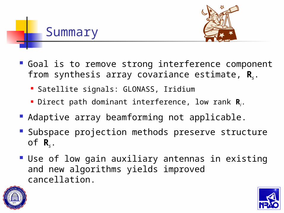
Goal is to remove strong interference component from synthesis array covariance estimate, Rs.
Satellite signals: GLONASS, Iridium
Direct path dominant interference, low rank Ri.
Adaptive array beamforming not applicable.
Subspace projection methods preserve structure of Rs.
Use of low gain auxiliary antennas in existing and new algorithms yields improved cancellation.
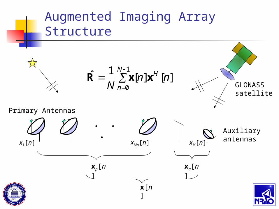
Augmented Imaging Array Structure
GLONASSsatellite
. . .Auxiliaryantennas
Primary Antennas
x1[n] xMp[n] xM[n]
xp[n] xa[n]
x[n]
][][1ˆ
1
0nn
NH
N
nxxR
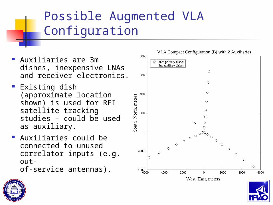
Possible Augmented VLA Configuration
Auxiliaries are 3m dishes, inexpensive LNAs and receiver electronics.
Existing dish (approximate location shown) is used for RFI satellite tracking studies – could be used as auxiliary.
Auxiliaries could be connected to unused correlator inputs (e.g. out-of-service antennas).
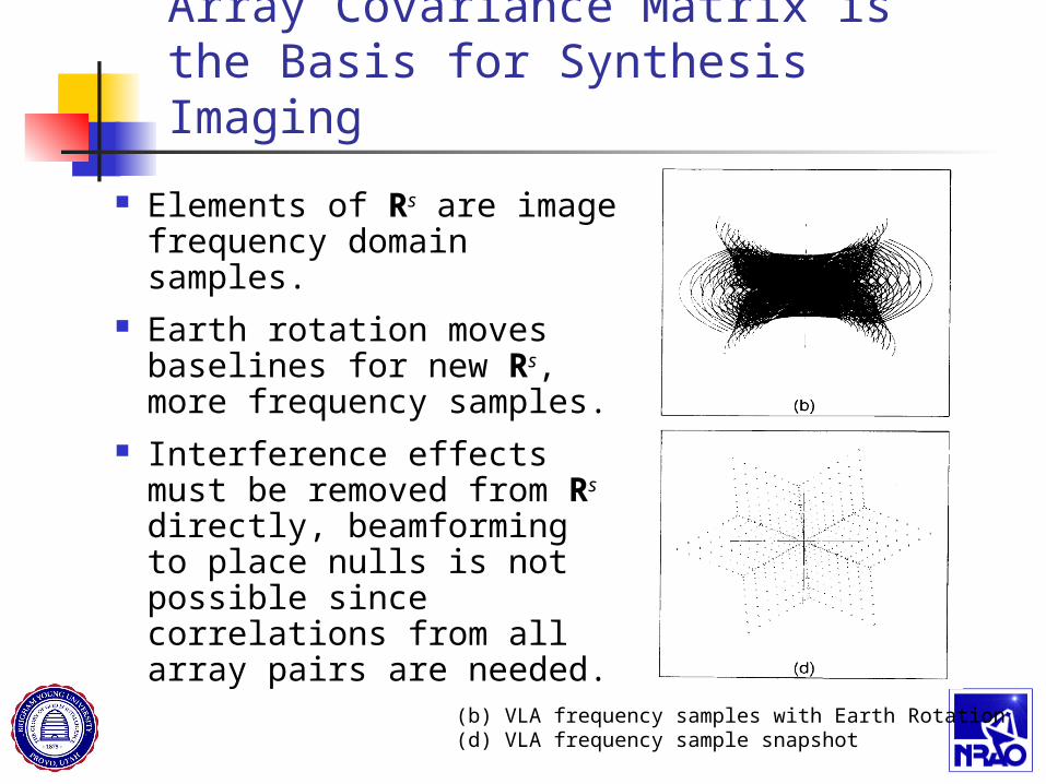
Array Covariance Matrix is the Basis for Synthesis Imaging
Elements of Rs are image frequency domain samples.
Earth rotation moves baselines for new Rs, more frequency samples.
Interference effects must be removed from Rs directly, beamforming to place nulls is not possible since correlations from all array pairs are needed.
(b) VLA frequency samples with Earth Rotation(d) VLA frequency sample snapshot
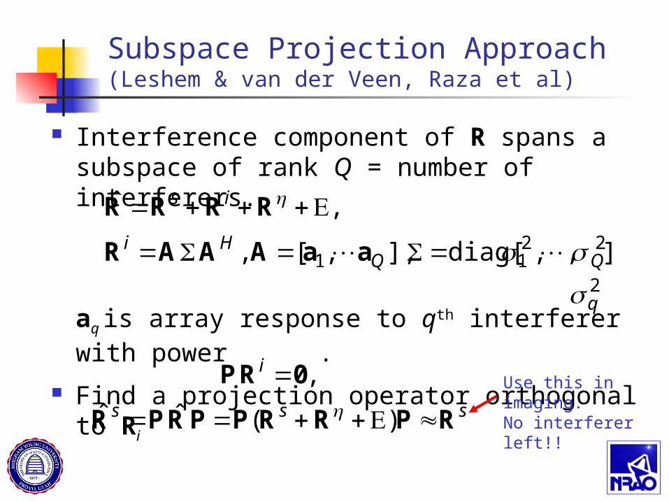
Subspace Projection Approach (Leshem & van der Veen, Raza et al)
Interference component of R spans a subspace of rank Q = number of interferers.
aq is array response to qth interferer with power .
Find a projection operator orthogonal to Ri
].,,diag[ ],,[,
,ˆ
2211 QQ
Hi
is
aaAAAR
RRRR
sss
i
RPRRPPRPR
0RP
)(ˆˆ
,
Use this in imaging.No interferer left!!
2q
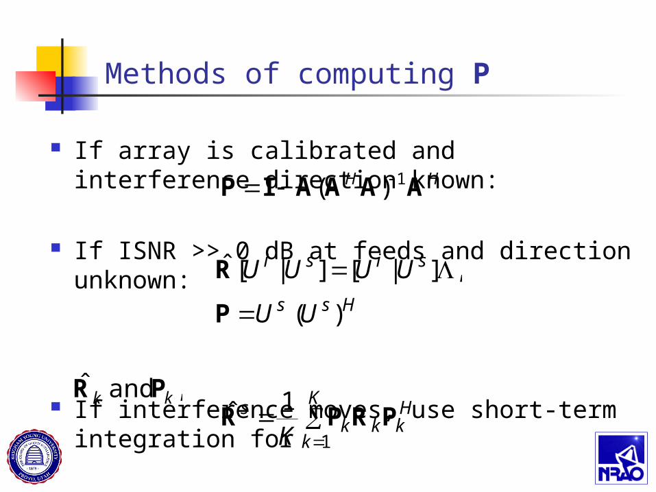
Methods of computing P
If array is calibrated and interference direction known:
If ISNR >> 0 dB at feeds and direction unknown:
If interference moves, use short-term integration for
HH AAAAIP 1)(
Hss
sisi
UU
UUUU
)(
,]|[]|[ˆ
P
R
, and ˆkk PR
Hk
K
kkk
s
KPRPR
1
1ˆ
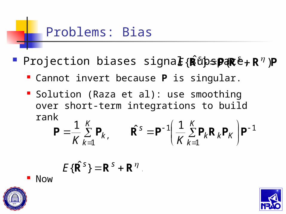
Problems: Bias
Projection biases signal subspace, Cannot invert because P is singular.
Solution (Raza et al): use smoothing over short-term integrations to build rank
Now
.)(}ˆ{ PRRPR ssE
.1ˆ1 1
1
1
1,
PPRPPRPP
K
kKkk
sK
kk KK
.}ˆ{ RRR ssE
Problems: Poor Subspace Estimates(main focus of this work)
Signal is many dB below noise.
High gain antennas help reject interferer, but make subspace estimation hard. Often INR 0 dB at feed.
Gain increases SIR by 70 dB.
Sometimes the signal or noise is identified as the interferer, and is projected out.
Poor interference subspace estimate leads to poor interference rejection from projection matrix P.
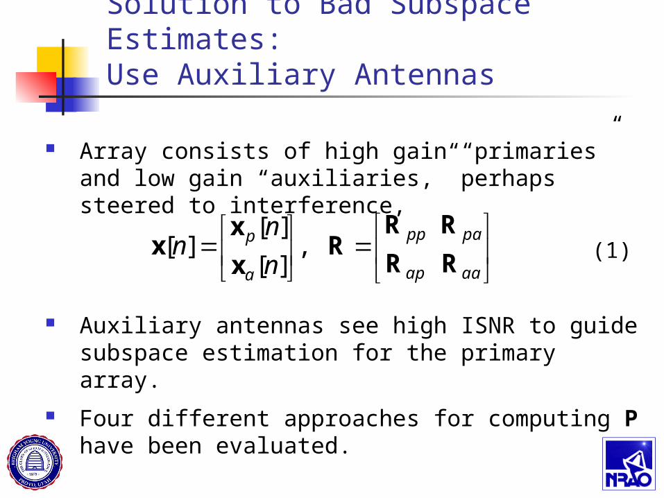
Solution to Bad Subspace Estimates:Use Auxiliary Antennas
Array consists of high gain “primaries” and low gain “auxiliaries,” perhaps steered to interference,
Auxiliary antennas see high ISNR to guide subspace estimation for the primary array.
Four different approaches for computing P have been evaluated.
.,][
][][
aaap
papp
a
p
n
nn
RR
RRR
x
xx (1)
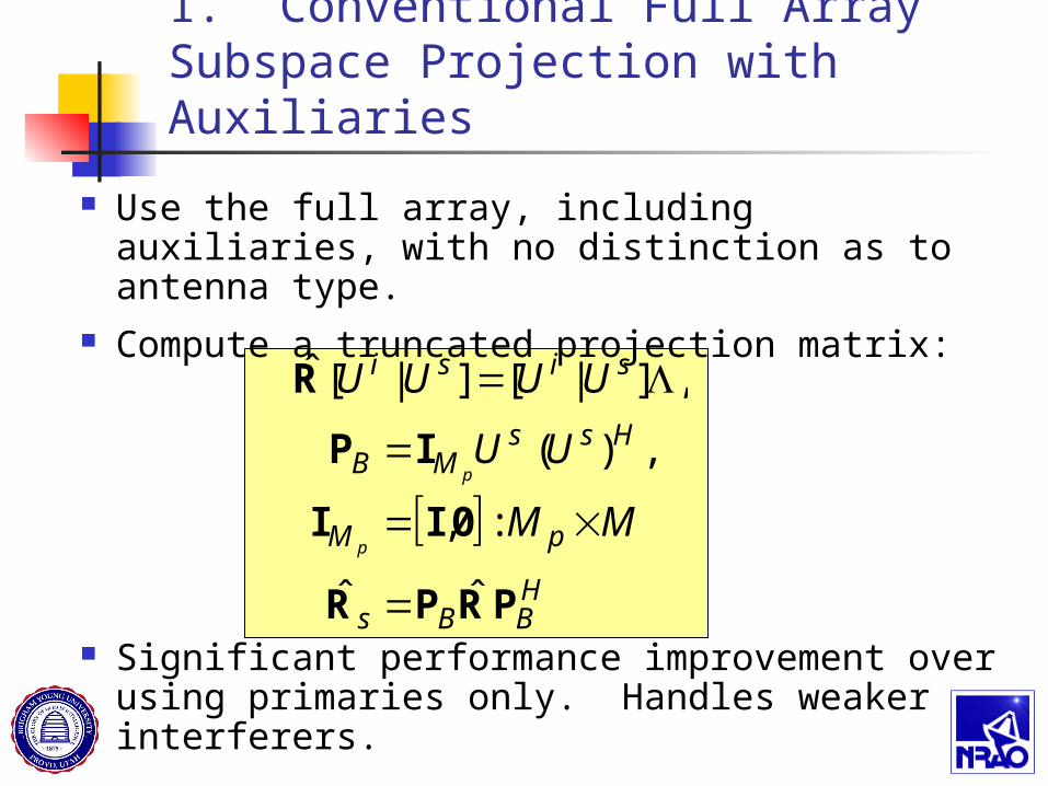
1. Conventional Full Array Subspace Projection with Auxiliaries
Use the full array, including auxiliaries, with no distinction as to antenna type.
Compute a truncated projection matrix:
Significant performance improvement over using primaries only. Handles weaker interferers.
HBBs
pM
HssMB
sisi
MM
UU
UUUU
p
p
PRPR
0II
IP
R
ˆˆ
:,
,)(
,]|[]|[ˆ
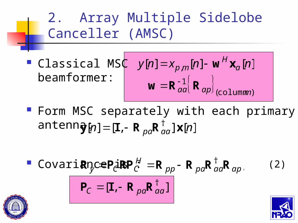
Classical MSC beamformer:
Form MSC separately with each primary antenna:
Covariance is :
2. Array Multiple Sidelobe Canceller (AMSC)
)column (
1
, ][][][
mapaa
aH
mp nnxny
RRw
xw
][],[][ † nn aapa xRRIy
],[
,
†
†
aapaC
apaapappHCCy
RRIP
RRRRRPPR
(2)
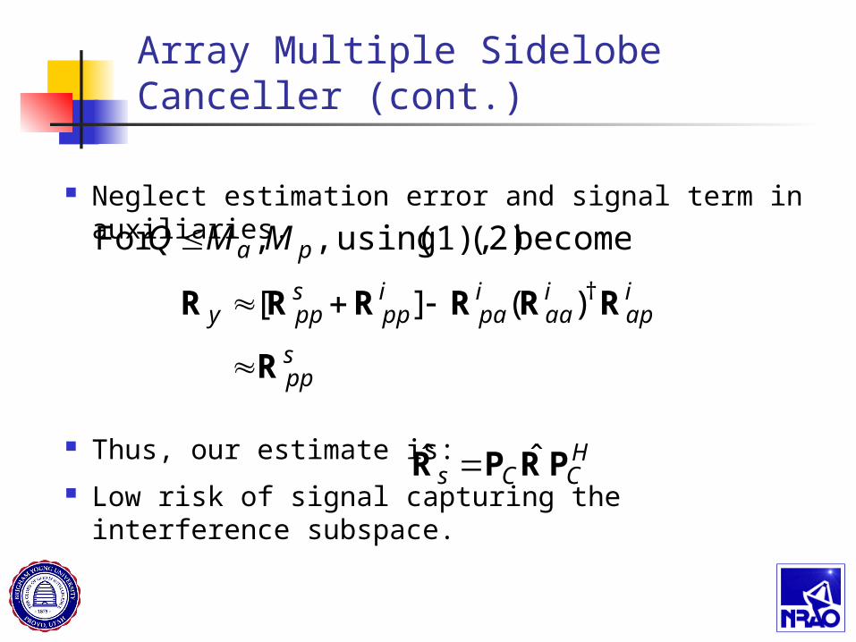
Array Multiple Sidelobe Canceller (cont.)
Neglect estimation error and signal term in auxiliaries.
Thus, our estimate is:
Low risk of signal capturing the interference subspace.
HCCs PRPR ˆˆ
becomes (2) (1), using ,,For pa MMQ
spp
iap
iaa
ipa
ipp
sppy
R
RRRRRR
†)(][
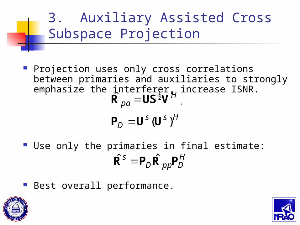
3. Auxiliary Assisted Cross Subspace Projection
Projection uses only cross correlations between primaries and auxiliaries to strongly emphasize the interferer, increase ISNR.
Use only the primaries in final estimate:
Best overall performance.
HDppD
s PRPR ˆˆ
HssD
Hpa
)(
,ˆ 21
UUP
VUSR
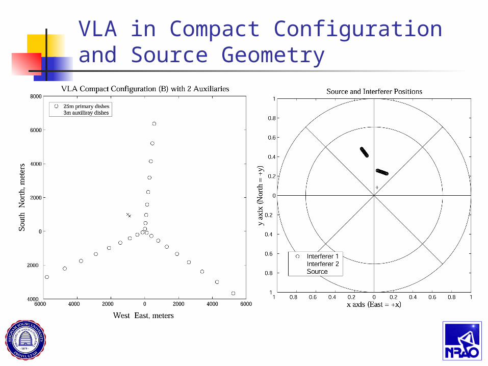
VLA in Compact Configuration and Source Geometry
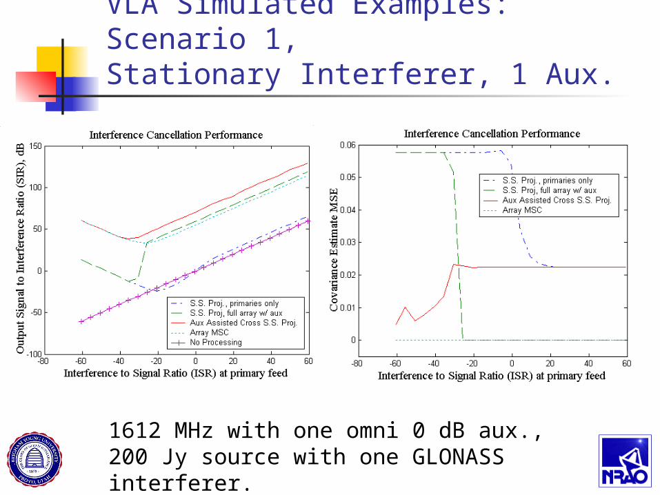
VLA Simulated Examples: Scenario 1, Stationary Interferer, 1 Aux.
1612 MHz with one omni 0 dB aux., 200 Jy source with one GLONASS interferer.
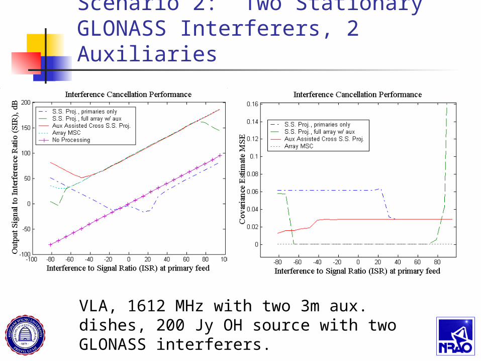
Scenario 2: Two Stationary GLONASS Interferers, 2 Auxiliaries
VLA, 1612 MHz with two 3m aux. dishes, 200 Jy OH source with two GLONASS interferers.
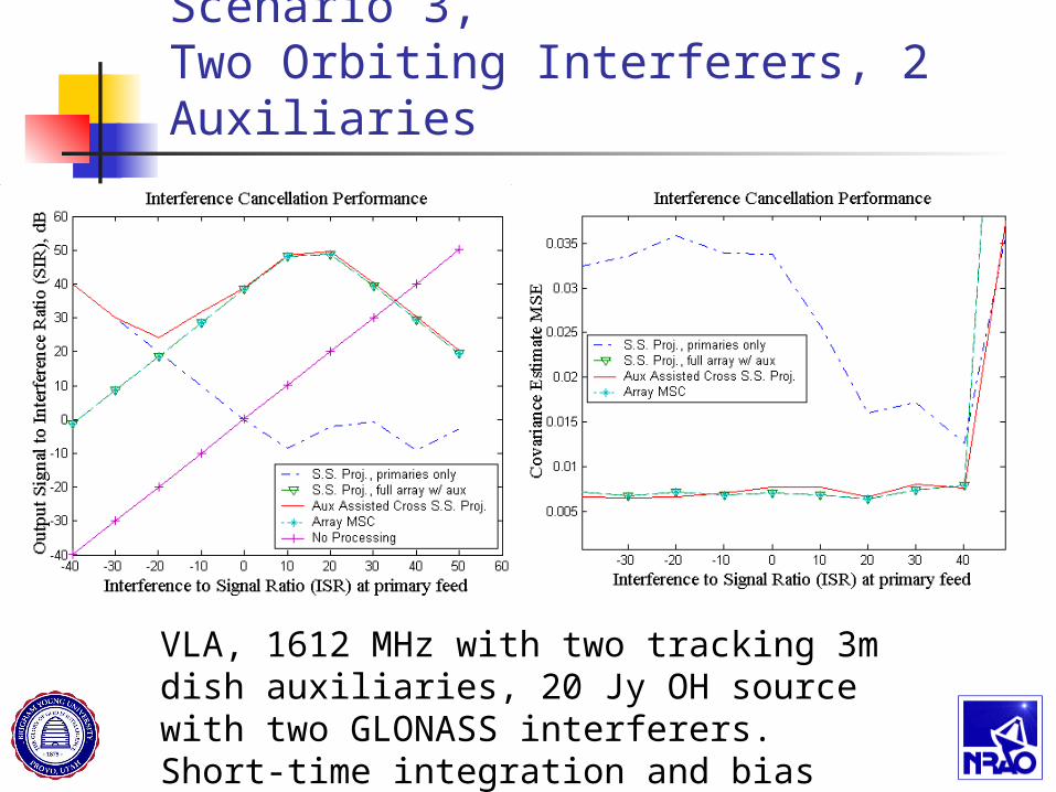
Scenario 3,Two Orbiting Interferers, 2 Auxiliaries
VLA, 1612 MHz with two tracking 3m dish auxiliaries, 20 Jy OH source with two GLONASS interferers. Short-time integration and bias removal.
Conclusions
In all cases, use of auxiliary antennas dramatically improved interference rejection.
Auxiliary assisted cross subspace projection performed best with weak interferer. No jammer detection needed.
AMSC has lowest covariance estimation error.
Auxiliary antennas are low cost, and can be added to existing arrays with modest investment.
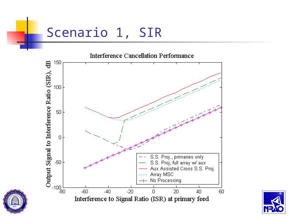
Scenario 1, SIR
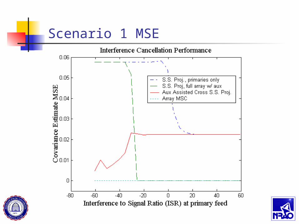
Scenario 1 MSE
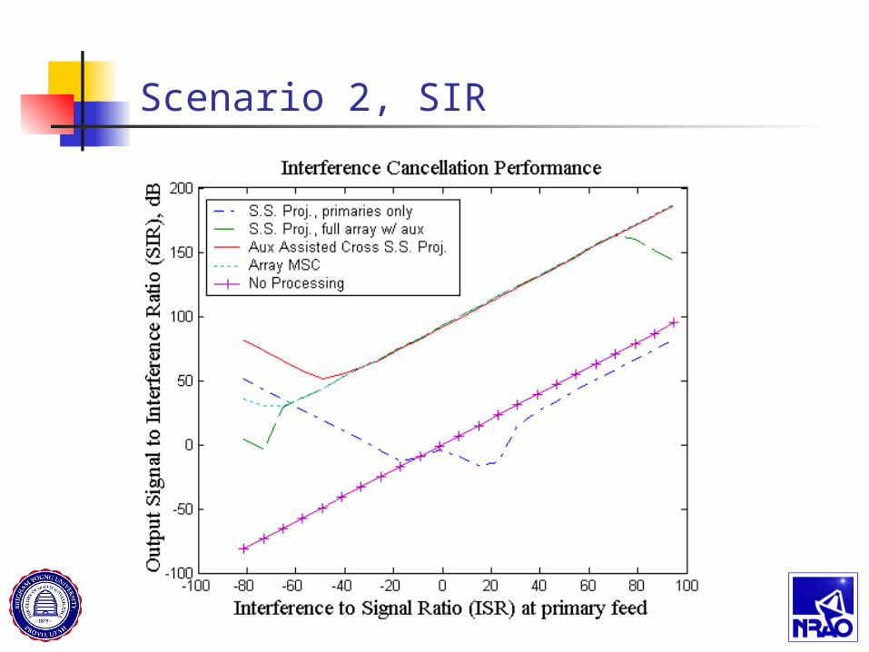
Scenario 2, SIR
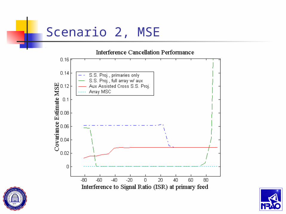
Scenario 2, MSE
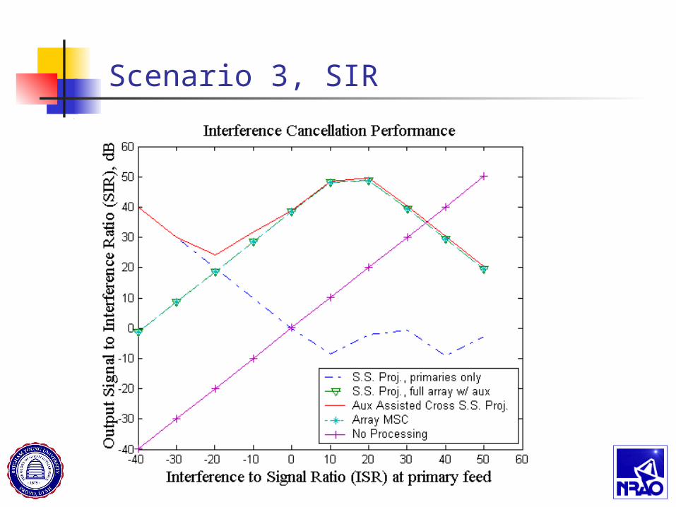
Scenario 3, SIR
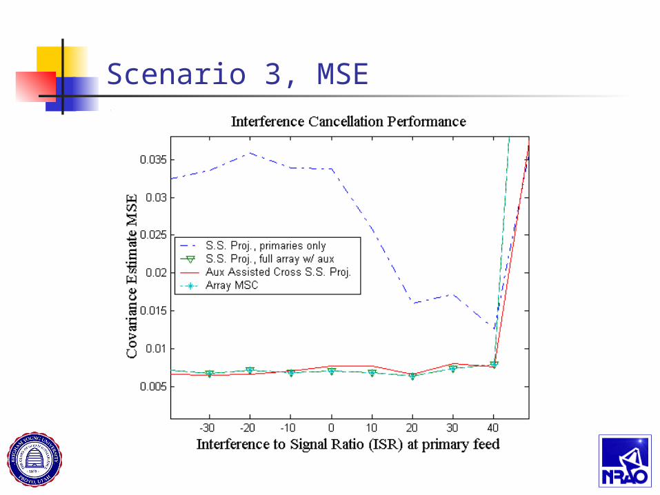
Scenario 3, MSE