Embed Size (px)
Citation preview

Frei
ght
Ele
vato
rD
oors
186 Educational Focus Compilation
EDUCATIONAL FOCUS: FREIGHT ELEVATOR DOORS
To many people in the industry, freight-elevator-doorcontrol systems seem complex. When they are up andrunning, they seem to work great, when the system isdown, it seems hard to even know where to start to trou-bleshoot. This does not have to be the case.
Freight-door controllers have come a long way from theold “clapper” relay logic door controllers with any numberof “Christmas Tree” switches that used to fill large doorcontrol cabinets with a maze of wiring. Today’s controllersare easier to install, have optional “slave” operation for simpleinterface with elevator controllers like Motion ControlEngineering, Inc. (MCE), they use the latest technologies likemicroprocessors or programmable logic controller alongwith proximity sensors for reliable trouble free operation.Freight-door manufacturers are now including light cur-tains as the standard door protection over the traditionalcontact reversing edge which allows user selectable auto-matic closing per the requirements of ASME A17.1-2000.You can be assured that in the latest freight-door con-trollers, consideration has been given to make the instal-lation, troubleshooting and maintenance as quick andeasy as possible.
Freight-door controllers start off with the followingbasic components:1. Door controller to elevator controller interface connec-tions typically for auto-open, inspection operation, fireservice and other control optional initiations and contacts.2. A processor unit using a microprocessor like a Program-mable Logic Controller (PLC) in order to keep the costdown and improve reliability.3. Door, gate and retiring cam motor control designed toprovide smooth reliable operation of what can be verylarge and heavy doors.4. A “zoning” method usually installed at the landing doorand activated by the retiring cam. The zone switch is usedto initiate only the landing door operators and push buttonsat the car’s landing destination.5. A reliable open and close limit switch arrangement forproper start, slowdown and sequence of operation of thedoors and gates.
To complete the door controller, today’s freight-doorsystems are fitted with easy-to-install safety edges such asnon-contact infrared light curtains for best protection, auto-matic or momentary pressure closing requiring an audiblesignal device. A power transformer is included. Transformerscan now be pre-wired and mounted within the controller cabi-
net making installation quicker by having to mount only onecontroller box. Physically smaller dimensions for micro-processors and PLCs have also eliminated the need for a secondcontrol box where the elevator has front and rear openings.
Let’s start with electrical interface requirements. Standardfreight-elevator-door controllers are equipped with SequenceOperation per EN81-1998, ASME A17.1-2000 and CSA B44-00.Sequence operation of the door and gate ensure that thecar gate does not begin to open until the bi-parting doorhas completed 2/3 of its opening before the car gate beginsto open, and that the car gate has finished 2/3 of its closingbefore the bi-parting door begins to close. This is to removethe tripping hazard caused by the lower panel of the bi-partingdoor by blocking the elevator car entrance with the cargate thus not allowing ingress or egress before the landingdoor is open. For door controllers designed for FirefightersEmergency Operation per ASME A17.1-2000, sequence ofoperation is not required during Phase 2 Operation in orderto allow faster operation of the door by the firefighters.
Freight-door controllers require the following initiations:u Retiring Cam – A constant initiation is required to pickthe retiring cam and lock the door for elevator travel. Oncethe doors are closed, the signal to lift the cam is receivedand the interlock functions to lock the door. Only after alocked signal is received by the elevator controller, aspart of the interlock circuit, is the car allowed to move.u Auto-Open – Momentary initiation allows the doors to auto-matically open once the car is leveling within the leveling zone.u Phase 1 Emergency Recall – A constant signal is requiredto initiate closing of the doors (in some cases a visual andaudible signal is provided to tell the operator to close thedoors). Reopening devices affected by smoke must be ignoredin this operation and, if the doors close automatically,they must be reduced in speed to keep their closing kineticenergy below 3.5 Joules or 2.5 ft-lb. The units for closingkinetic energy are not related to the closing force butrather the speed and mass of the car gate in the formulaKE=1/2mv^2. To illustrate an example of the calculationwe take a 100kg-car gate operating in slow speed at0.2mps (typical slow speed):
KE=1/2mv^2=1/2 x (100kg) x (0.2mps)^2=2 JoulesIf you are doing this calculation in imperial units, don’t
forget that the mass of the gate must be in units of slugsfor proper calculation.u Designated or Alternate Landing – During Phase 1 RecallOperation, this initiation will indicate to the freight-door
FREIGHT ELEVATOR DOOR CONTROL SYSTEMS EXPLAINED
by Steve Reynolds
03-09-1 pg186-195 2/11/09 10:17 AM Page 186

Educational Focus Compilation 187
EDUCATIONAL FOCUS: FREIGHT ELEVATOR DOORS
controller that the elevator is at the recall designated oralternate landing floor, and thus the door will remainopen awaiting use by the emergency personnel.u Phase 2 Emergency In-Car Operation “ON”, “HOLD” &“OFF” – Three separate initiations are required to indicatethe in-car operation of the elevator. Door operation andpush-button function are specific to each of the opera-tions. It should be noted that vertically sliding doors havespecific requirements different from passenger horizon-tally sliding doors.u Hall Door Button – Use the corridor door open andclose button control function initiation when switching toattendant operation. The latest freight-door controllers donot necessarily require corridor button cut-off in Phase 2Emergency Operation if the function is performed auto-matically within the door controller.u Inspection Circuit Cut-Off – During inspection, it is impor-tant to disable the freight-door controller using this initiationto avoid unwanted door operation.
In order to complete the interface, signals for car gate
fully open and for door fully closed, along with the requisiteinterlock and gate contact signals, are provided.
The freight door controller is typically installed in themachine room. Wiring from the freight door controllerneeds to connect to three places, the elevator car, thehoistway landing doors and the elevator controller.Therefore, it makes sense to install the controller in themachine room rather than the car top. Wiring to theelevator controller is required to facilitate the initia-tions and signals mentioned above. Another set ofwires goes to the elevator car for the car gate components,retiring cam, reopening device and other components.Finally, a set of wiring also goes down or up the hoist-way wall near the landing doors as wiring is requiredfor the hoistway door motors, hall push buttons andinterlock circuits.
Hoistway wiring offers the best opportunity for alter-nate methods to reduce the amount of wiring. One suchmethod that has been around for many years is the use ofthe zone switch. A zone switch integrated with the door
Figure 1: Master limit freight-door control
Freight
Elevato
rD
oors
03-09-1 pg186-195 2/11/09 10:17 AM Page 187

188 Educational Focus Compilation
EDUCATIONAL FOCUS: FREIGHT ELEVATOR DOORS
interlock allows a single set of wiring for all door motorsand landing door push buttons. The wires are connectedin parallel to one side of the zone switch at each floor.The operators and push buttons for each floor are wiredto the other side of its respective zone switch. When theelevator car is within the landing zone and the retiringcam is extended, the zone switch will initiate the motorsand push buttons of that floor only. Much installation timeand wiring is reduced this way.
Door limit switches also offer an opportunity to reducethe amount of hoistway wiring. Traditionally, at least twoswitches were provided for each landing door and acti-vated by the door for open and close slowdown. Theseswitches were either wired in series or parallel to each ofthe landing doors before being brought back to the doorcontroller. Every individual switch has to be adjusted andwhen many floors necessitated many switches, trou-bleshooting is like trying to find the one burnt-out bulb ina string of Christmas tree lights.
Another method is to mount two switches on the ele-vator car using proximity sensors. The latest in proximitysensor technology offers high reliability and the extendedranges necessary to control the landing doors from theside of the elevator car using a “master limit” arrange-ment. Figure 1 illustrates how the proximity sensors con-trol slowdown of the landing door from the car. With thedoor motor and hall push buttons properly zoned-in, op-eration of the landing door is controlled by the proximitysensors that function to control the speed of the landingdoor as it operates.
The advantage of this method of door control can befound in two items: 1) proximity sensors by nature donot require any physical contact, can only sense metallictargets (not effected by dirt, grease or water) and aresolid state lasting millions of cycles. Therefore, afterinstallation, no further adjustment or maintenance isrequired, and 2) since one set of limit switches operateall landing doors in that line, significant savings arehad in the installation and wiring compared with tradi-tional methods which require switches for each land-ing. The savings are a multiple of the number of floorsthe elevator serves.
On the car you will find a gate operator, a gate con-tact, a reopening device, a retiring cam, limit switchesand door/gate operation push buttons. The door openand close push buttons are typically part of the car-operating station. Ideally, #14AWG size wires shouldbe used for the car gate operator and retiring cammotor, although #18AWG will suffice in many cases,and these can be doubled up when necessary. Controlconductors are sufficiently served with #18AWG for mostfreight-door applications.
Once the hoistway door and car gate componentshave been wired per the manufacturer’s prints, it is timeto move on to the operation of the doors. It is importantto note the operation of the hoistway landing door andcar gate are dependant of each other because of theirsequence of operation. The car gate will not functionproperly without the proper operation of the landingdoor and vice-versa. Begin your initial startup with thedoors closed and the elevator leveled at a floor. Stay atthis floor until the door is working properly there. Startby making sure the retiring cam is extended and thezone relays or zone switch is fully activated. The zoneswitch usually has an input to the controller that willinitiate the door function, begin by finding this input. Itis usually part of a series of contacts starting with azone contact followed by stop switches or other stopdevices like unlocking device switch.
Once you know the controller is initiated throughthis input, make sure the input from the slowdownswitches is functioning properly. Typically, the normalopen speed input will be high for both door and gateand will go to low to initiate the slowdown. Make sureboth door and gate open limits are high when the doorand car gate is closed. The close limits should be low.Initiate the open push button. The open relay and thedoor and gate relay should start the motors. This iswhere you will find out if the three-phase motors arephased properly. If the door or car gate motors run inthe wrong direction and want to close the door ratherthan opening, it is likely the phase is reversed. Freightdoors use three-phase motors and can easily be reversedby switching any two wires to the motor. When you getthe doors to open, note that the landing door will openfirst and, once it reaches its open limit, the car gate willbegin to open (sequence operation). After both door andcar gate reach their open limits, a timer will time outthe final operation. This timer is typically user ad-justable. The close operation is more complex. Now,you will need to make sure your reopening device isfunctioning properly before you will be able to close thedoors. A fail-to-safe operation will not allow properclosing unless the input is high when the device is notobstructed. You will also need to apply continuouspressure to the close button unless momentary pres-sure or automatic close has been selected.
Once the basic operation is complete, try the initia-tions for the Emergency Operations and check forproper function. A properly functioning door and cargate at the initial floor will make adjustment easierwhen moving to the remaining floors in line. Typically,if the car gate was working at the initial floor, you will
Frei
ght
Ele
vato
rD
oors
03-09-1 pg186-195 2/11/09 10:17 AM Page 188

Educational Focus Compilation 189
EDUCATIONAL FOCUS: FREIGHT ELEVATOR DOORS
only have to check the functions of the landing door asyou move the car to the remaining floors for adjust-ment. Freight-elevator doors, installation and properadjustment are key. Once all the floors have been adjustedand the system is operating properly, it should provideyears of trouble-free operation.
With consolidation of the elevator industry and thedemand for quicker installations and easier commis-sioning, the application of new technologies and func-tions has demanded changes of the freight-door manu-facturers. There is the possibility of other devices andfeatures that can be applied someday to freight-doorcontrol. For example, many customers are asking whymotor drives have not been applied to freight doors.There has been some limited success in this researchbut motor drives by nature have hurtles to overcome.Because they use pulse-width modulation to providespeed control, the drive signals have high order har-monics that cause noise and cannot be transferredalong lengthy travel or hoistway cables due to interfer-ence that will cause possible motor burnouts.
Closed-loop operation is another industry buzzwordbeing asked of freight-elevator doors. The true definitonof a closed-loop controller basically ensures that the speedof the motor is regulated by the drive system despitefluctuations in load, similar to a car cruise control. Al-though accurate speed control may be ideal for elevatortraction motors or similar applications, it has the poten-tial for applying relatively high forces under heavyloads in order to keep its speed. This is not required indoor control and not desired where freight handlersand passengers are operating the doors. Best suited fortheir application, freight door motors are typicallyhigh slip in order to allow smooth safe operation ofthe doors. Precise speed control is not required.
If these hurtles are overcome, however, there may bea place for these technologies in freight doors. With theadvent of the machine-room-less elevator and otherfantastic new methods of elevating, the future for freight-elevator-door control may look entirely different than itdoes today.
Steve Reynolds is with Product Development at The Peelle
Company Ltd.
Freight
Elevato
rD
oors
03-09-1 pg186-195 2/11/09 10:17 AM Page 189

Frei
ght
Ele
vato
rD
oors
190 Educational Focus Compilation
EDUCATIONAL FOCUS: FREIGHT ELEVATOR DOORS
IntroductionThis article is meant to provide field mechanics with a
general step-by-step guide for the successful installation offreight elevator doors and gates. It should be noted, how-ever, that each manufacturer of freight elevator doors pro-vides specific installation instructions with their equipment.These job specific installation instructions should be fol-lowed in lieu of the general instructions set out below.Scope
While the ASME A17.1-2000 Code recognizes severaltypes of freight elevator entrances (Section 2.11.2.2ASME A17.1-2000 Code), this article will cover only ver-tically sliding bi-parting counterbalanced freight elevatordoors and gates. Bi-parting freight elevator doors consistof two panels, one that slides upward and one that slidesdownward when opening. Vertical bi-parting doors pro-vide full opening width access to the inside of the car, butrequire very little additional hoistway space. Bi-partingdoors can be applied in most hoistway situations, includ-ing short spandrel heights, shallow pit, and low over-heads. They can be power or manually operated and aredesigned to match the capacity and class of loading of thefreight elevator.General Code Requirements and Considerations
By definition, a freight elevator is “. . .an elevator usedprimarily for carrying freight, and on which only the operatorand the persons necessary for unloading and loading thefreight are permitted to ride” (Section 1.3, ASME A17.1-2000Code). Car gate and car door requirements are set forth inSections 2.11, 2.12, 2.13, 2.14 and 2.16 of the ASMEA17.1-2000 Code. These sections also include the require-ments for the contacts, interlocks and power, operationassociated with freight elevators.Hoistway Safety
Prior to starting the installation work, ensure that allnecessary barricades are in place and that they meet theOSHA and local authority requirements. This is especiallytrue in view of the fact that, very often, the door installa-tion work is performed from a running platform.
In addition, you will most certainly need a hoist or chainfall for the movement of the freight door materials. Makesure the hoist, hoist support, hoist chains, slings, straps,and any other accessories that will be used to hoist thedoor panels into position, are capable of safely supportingthe door panels. Carefully inspect each component of thehoisting system for damage or wear before use.
Identification and Handling of Freight DoorsFreight elevator door panels require special handling.
Always transport and store the freight door panels verti-cally, with the heavy side down. Never transport orstore the freight door panels laying flat.
Each door is identified with a number (Figure 1). Themanufacturer’s door number corresponds with the land-ing designation set out in the approved layout drawings. Thedoor number is used throughout the job to identify mateddoor panels, guides and other associated hardware. Typi-cally, the corresponding numbers are located on the sideangles of the upper and lower door panels.
Freight door installation and maintenance is principallyaccomplished from the hoistway side of the opening. Forthis reason, all freight door equipment is marked left orright hand, as viewed from the hoistway (standing in thecar looking out). For example, an interlock mounted onthe right hand side of the opening, viewed from the hoist-way side, is properly identified as a right hand interlock.The Field Survey
A field survey of the hoistway is the single most importantstep in the freight elevator door installation process. It isalso the step most ignored by elevator mechanics.
First, check floor heights, opening heights, and returnson the job, and compare them with your approved layoutdrawings. From the layout and your own measurements,make sure that floor heights are adequate so that alldoors can be opened fully without interfering with closeddoors at floors above or below. If the height is not adequate
INSTALLING FREIGHT ELEVATOR DOORSby Joseph De Simone
Figure 1: Panel identification
03-09-1 pg186-195 2/11/09 10:17 AM Page 190

Educational Focus Compilation 191
EDUCATIONAL FOCUS: FREIGHT ELEVATOR DOORS
at a particular floor or floors, it will be necessary to installa pass type door. (This should have been noted on the lay-out and the appropriate special materials provided.) Anydiscrepancy here must be immediately brought to the at-tention of the freight door manufacturer. Likewise, checkthe distance between the jamb and the side wall to insurethat there is sufficient space for the door operators, inter-locks, retiring cam and other freight door components.Again, any discrepancy here must be immediately reportedto the freight door manufacturer.
Finally, verify the distance from the car platform to the en-trance sill, and confirm that it is the same across the face ofthe opening at each landing. The distance from the car plat-form to the entrance sill must not cause the running clear-ance between the platform and the doors to drop below 1/2inch (13 millimeters), or increase to more than 1-1/2 inches(38 millimeters). Also, at each opening, verify that all sillsare level. Sills must be level to a tolerance of 1/8 inch (threemillimeters) for every eight feet (2,440 millimeters).
Remember, an incorrect hoistway equals a bad instal-lation. If after completing the field survey, it is determinedthat the existing hoistway conditions are incorrect or differentfrom that depicted in the approved layout drawings, stopand contact the freight door manufacturer. Do not assumeresponsibility for an incorrect hoistway.Step 1: Installation of Door Guide Rails
The entrance frames for a freight elevator door areusually installed by others. Since door guide rails run almostcontinuous from the bottom to the top of the hoistway,and are attached to the entrance frames, it is essentialthat the frames be installed directly above one another inproper relation to the elevator main guide rails. Theframes must be held square and plumb to within 1/4 inch(six millimeters).
Make a thorough survey of the conditions, and checkthem against your approved door layout drawings. Thiscan be done by one of two methods: Method 1 – drop aplumb line down the hoistway and use a guide rail gaugeangle to set the guide rails, or Method 2 – utilize the car
platform as a template. For purposes of this article, wewill describe the steps involved in Method 1. Method 2assumes that the car platform travel is true and plumbthroughout the entire hoistway and is not the preferredmethod for guide rail installation.
Locate the guide rail gauge angle provided by the freightelevator door manufacturer (Figure 2). The guide railgauge angle contains three factory-made marks at eachend: Mark 1 (towards the center of the opening) indicatesthe edge of the jamb. Mark 2 (center) is the edge of theguide. Mark 3 is the center of the bolt hole. These threemarks, along with a plumb line, are used to survey thehoistway entrances and insure proper opening width foryour freight door equipment.
Drop and secure a plumb line from top to bottom of thehoistway and verify the distance from the plumb line toeach jamb. The plumb line should be set approximatelytwo inches (50 millimeters) off the sill. This plumb linemust remain secure throughout the guide rail installation.
At the top, middle, and bottom of each opening, makea temporary mark on the guide rail gauge angle at theplumb line. Upon completion, make a permanent mark onthe guide rail gauge angle at the halfway point betweenthe two outside temporary plumb line marks (Figure 3).At each opening, align the permanent plumb line markon the guide rail gauge angle with the plumb line. Whileholding the guide rail gauge angle level, verify on bothsides of the hoistway: (1) the edge of guide mark does notfall inside the entrance at either side of the hoistway, and(2) the center of bolt hole mark does not fall closer than1/2 inch (13 millimeters) to the outside of the edge ofjamb. If you have either of these conditions, stop and callthe freight door manufacturer immediately.
Guide rails are manufactured and shipped in pairs (leftand right) for specific landings. There are three types ofguide rails – lower, intermediate and upper. Upper guidesare marked to correspond to the opening for which theyserve as the upper guide. Intermediate guides act as theupper guide for a lower opening and extend up to act as
Figure 2: Gauge angle
Figure 3: Permanent mark
Opening Width
Edge ofJambMark permanent
mark
plumbline
Place permanent markhalfway between two
outside temporary marks
Gauge Angle
Edge of Jamb
Edge of Guide
Center Line of Bolts
Plumb Line
PassGuide
PassGuide
Freight
Elevato
rD
oors
03-09-1 pg186-195 2/11/09 10:17 AM Page 191

Frei
ght
Ele
vato
rD
oors
192 Educational Focus Compilation
EDUCATIONAL FOCUS: FREIGHT ELEVATOR DOORS
the lower guide for next opening. Intermediate guides aremarked to correspond to the opening for which theyserve as the upper guide. Lower Guides are marked tocorrespond to the opening for which they serve as thelower guide, followed by the letter “A.”
Beginning with the lowest opening, measure up fromthe finished sill one half the designed opening height, asshown on the approved layout drawings, and place a centerline reference mark on each jamb (Figure 4). Using the guiderail gauge angle and level, make sure that the referencemarks are level with each other. If the marks are not level,use the lower of the two sides as the reference point.
On one side of the opening, set the bottom of theupper or intermediate guide even with the centerline reference mark (Figure 5). Please note that thereis a bright yellow label on the guide rail identifying thebottom end of the guide rail. Do not consider the strapwelded across the upper/intermediate guide rail whenlining up the bottom of the guide with the center linereference mark. Clamp the guide rail into position.Check the side-to-side position of the rail at severalplaces along its length using the guide rail gaugeangle and plumb line. Please note that intermediateguides extend upward to within 1/2 inch of the centerline reference mark of the opening above. If theguide rail is too long, the upper end may be sawed offto obtain the 1/2 inch (13 millimeter) clearance. If sig-nificantly more or less than 1/2 inch (13 millimeter)clearance exists, contact the freight door manufacturerimmediately for assistance.
Drill the appropriate hole at the top of every slot onthe guide rail within the entrance frame, and everyfourth slot outside the entrance frame. Apply a smallamount of lubricant to the threads of the self-tappingbolts provided by the manufacturer, and insert intoholes. It is important that you do not use washersunder the head of the guide rail bolts. Guide lugs areused to secure guide rails extending beyond the steelentrance frame.
Using the plumb line and level, verify that the guide railis plumb and true. Should the guide rails vary in and outfrom the jamb, it will be necessary to shim behind the guiderail to insure the rail is plumb and true. Slotted shims andkicker shims are provided for this purpose. Please notethat excessive shimming of the door guides may void theentrance fire rating, and may cause your installation tofail inspection.
After the upper/intermediate guide is set, install thelower guide rail 1/2 inch (13 millimeters) below thecenter line reference mark, using the same methoddescribed above.
Install all of the guide rails on one side of the hoistway,then return to the lowest landing and install the oppositeside guide rails. Begin installation at the lowest landingand progress up the hoistway. Use the guide rail gaugeangle to maintain accurate distance between guide rails,and to assure the second set of guide rails are exactlyparallel to the first.Step 2: Installation of the Door Operators
Mount a power door operator to the upper/interme-diate guide on each side of the opening with the motoron the back side (nearest the wall) and the junction box
Figure 4: Center line mark
Figure 5: Guide placement
03-09-1 pg186-195 2/11/09 10:17 AM Page 192

Educational Focus Compilation 193
EDUCATIONAL FOCUS: FREIGHT ELEVATOR DOORS
down (Figure 6).Each Operator hasa 3/8 inch (9.5 mil-limeters) roll pin be-tween the mountingbolt holes. Positionthe roll pin in thehole provided in theupper/intermediateguide rail to estab-lish proper locationand assist in themounting operation.Using the mountinghardware providedby the freight doormanufacturer, boltthe door operatorsto the side of theupper/intermediateguide rails in the
holes provided. Please note that for pass type doors, thedoor operator mounting holes are located in the passguide rail.
Step 3: Installation of the InterlockMount the interlock and side opposite latch (when applic-
able) to the lower end of the upper/intermediate guide rail,in the holes provided just above the center of the opening,using the mounting hardware provided by the freight doormanufacturer (Figure 7). Please note that for pass type
doors, the interlock mounting holes are located in the passguide rail. Refer to the approved layout drawings to confirmwhich side of the hoistway the interlocks mount. Do notinstall the interlock roller arms at this time.
When applicable, mount the center latch in the centerof the sill and lintel. It is very important that the center ofthe opening be accurately located, and that the devicesare accurately located in relation to this centerline.
Step 4: Installation of the Door PanelsThe lower door panel is installed first. Place the door
panel in an upright position on the floor, using woodenblocks beneath the side angles to guard against damageand injury. Wrap lifting straps around both door arms ofthe lower door panel and carefully lift the lower doorpanel into the opening (Figure 8). Important! Be sure thehoist, hoist support, hoist chains, slings, straps, and anyother accessories used to hoist the door panels into posi-tion, are capable of safely supporting the door panels.Carefully swing the lower door panel into position betweenguides and lower the door panel onto the guide stops orsill stops.
Push the door panel against the guide bolts. If both sideangles on the door panel are flat against all the guidebolts, twist is not present. You may proceed with installation.If both side angles are not flat against the guide bolts, thedoor panel has some twist that must be removed beforecontinuing with the installation of the door panel.
If twist exists, one method of removing it is as follows:(1) While the door panel is still hanging from the hoist,place a block at one corner of the door panel between theedge of the panel and the elevator platform. Grip the doorpanel at the corner diagonally opposite the blocked corner,and apply pressure to the upper edge of the panel oppositethe observed twist.
Figure 8: Door panels
Figure 7: Interlock
Figure 6: Door operator
Freight
Elevato
rD
oors
03-09-1 pg186-195 2/11/09 10:17 AM Page 193
194 Educational Focus Compilation
EDUCATIONAL FOCUS: FREIGHT ELEVATOR DOORS
Once you have determined that you are working with aflat door panel, install four guide shoes in the pre-drilledtapped holes on the door panel side angle. The guide shoemounting bolts should be loosely tightened at this point. Theguide shoes will be adjusted and tightened after the doorchains have been installed.
After installing guide shoes, lower the door panel to itsfull open position. Where applicable, adjust the guide stopsto insure that the lower door panel is 1/8 inch (three mil-limeters) below the sill and level from side-to-side. You cannow remove the lower door panel from the hoist.
After installing the lower door panel, install the upperdoor panel following the above steps. Hoist the upper doorpanel into an open position that is level from side-to-sideand 1/8 inch (three millimeters) above the lintel. The upperdoor panel should remain suspended from your hoist untildoor chain rods and chains are fully installed.Step 5: Installation of the Chain Rods and Chains
Hand actuate the latch on the interlock and insert thetemporary hold open clip provided by the freight elevatordoor manufacturer. Holding the chain rod with the threadedend down and the slots parallel to the door panel, pass thechain rod up through the latch and rod guide on the inter-lock. Insert the threaded end of the chain rod through thelower door panel pick-up and rod positioner. Allow thechain rod to rest on the temporary chain rod spacer that isstrapped to the rod. Thread a hex nut and lock nut onto thechain rod. Adjust and loosely tighten the rod positioner,located on the door panel door arm, to get the chain rodas true and plumb as possible at this time. Please notethat it is important to get the chain rod true and plumb;failure to do so will result in poor operation of thefreight door and could cause damage to the interlock.
The door chain isprovided with a dooradjustment rod atone end. Drop thedoor adjustment rodthrough the upperpanel chain hitchand secure it. Pullthe wire loop andchain through theoperator, to threadthe chain over theoperator sheave.(Figure 9). Pull thechain down to thetop end of the chainrod. Do not attachto the chain rod atthis time.
Locate the door panel gauge angle. Verify that the lengthof the door panel gauge angle equals the opening heightof the door panels plus 1/4 inch (six millimeters). Hoistthe upper panel to its full open height and be sure that thelower door panel is resting firmly on the guide stops. Usethe door panel gauge angle to verify that the doors are attheir full opening height. With the door panels at their fullopen height, cut the door chain to correct length and attachit to the chain rod. Repeat the process on the opposite side,and remove the chain rod spacers from both chain rods.
Carefully transfer the weight of the upper door panelfrom the hoist to the chain. Once all of the panel’s weightis supported by the chains, un-strap the upper door panelfrom the hoist. Adjust and tighten the door panel guideshoes to allow free movement of the door panels. Limitside-to-side play to about 1/16 inch (two millimeter).Close the door panels and remove the temporary inter-lock open clip. Using a level, check both door panels toinsure that they are square and level. Check to see thatthe chain rods are approximately centered in the rodguides. Tighten the rod positioner on the lower doorpanel door arms, adjust if necessary to center, and plumbthe chain rods. Secure the rod positioner in place.
With the interlock in the locked position, the door panelshould not be able to open more than 3/4 inch (19 millimeters).The lower chain rod may be adjusted slightly to accomplishthis. Please note that any adjustment to the lower chain rodsmust be compensated for by adjusting the door adjuster rod onthe upper panel to maintain door open height (e.g., if the lowerchain rod hex nuts are loosened two turns, the upper dooradjuster rod square nuts must be tightened two turns.Step 6: Installation of the Door Limit Switch
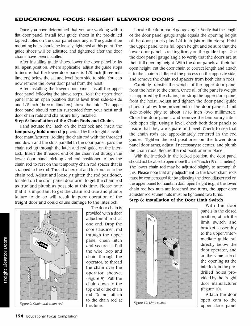
With the doorpanels in the closedposition, attach thelimit switch andbracket assemblyto the upper/inter-mediate guide raildirectly below thedoor operator, andon the same side ofthe opening as theinterlock in the pre-drilled holes pro-vided by the freightdoor manufacturer(Figure 10).
Attach the dooropen cam to theupper door panelFigure 9: Chain and chain rod Figure 10: Limit switch
Frei
ght
Ele
vato
rD
oors
03-09-1 pg186-195 2/11/09 10:17 AM Page 194

Educational Focus Compilation 195
EDUCATIONAL FOCUS: FREIGHT ELEVATOR DOORSEDUCATIONAL FOCUS: FREIGHT ELEVATOR DOORS
bracket and adjust to a middle position. There is a channelon the back side of the door open cam. This channel fitsover the square nut that secures the upper chain rod, andprevents any movement. Adjust the nylon gib so that thedoor open cam properly actuates the limit switch.
Open the door one-to-two inches (300-to-600 millimeters).Mount the door closed cam on the upper door panel in theholes provided by door manufacturer at the upper end of thedoor side angle. Adjust to a middle position, and check tomake sure that the door closed cam clears the door operator.
When applicable, attach an Auto-Sta Set Switch to theguide stop on the interlock side of the hoistway. TheAuto-Sta Set Switch is actuated by a permanent cam angleattached to the lower door arm. Adjust the position of theAuto-Sta Set Switch by means of the slot in the mountingbracket, so that the switch is actuated when the lowerdoor is 1/4 inch to 3/4 inch from full open.Step 7: Installation of the Emergency Unlocking Devices
When applicable, install the emergency unlocking device(EUD). Please refer to the approved layout drawings, andnote the designated floors for the EUD installation.
Drill a hole through the hoistway wall. This hole shouldbe aligned as closely as possible to the hole in the top ofthe interlock roller arm. Install the EUD pipe through thehoistway wall. Attach EUD box to EUD pipe on hall sideusing the mounting hardware provided by the freight elevatordoor manufacturer. Hold the EUD box in a plumb position andthen, using the hole in EUD box, drill the necessarymounting holes and fix the EUD box in position. Threadthe EUD chain and wiring through the EUD pipe from thehall/box side. Using an “S” hook, attach the EUD chain tothe hole at the top of the interlock roller arm. (Figure 11).
Operation of the interlock by the pull chain unlocks thefreight doors when the car is not present at the landing.For this reason, please limit access to the emergency un-locking device (EUD) keys.
Figure 11: EUD
ConclusionThis completes the mechanical portion of the freight
door installation process. Still remaining is the mechanicalinstallation of the car gate, hoistway and electrical wiring,and installation of the freight elevator door controller, allof which are beyond the scope of this article. It is importantto reiterate that the steps set out in this article are generalin nature. Please consult the specific installation instructionsprovided by the freight elevator door manufacturer beforestarting your job.
Joseph De Simone is vice president of Sales at Courion. His entire 40-year career has been in the freight elevator door industry, workingin Chicago, New York, and currently in St. Louis. He has been anactive participant and past treasurer of the Chicago Elevator Associa-tion. De Simone also has been an active member and supporter ofNational Association of Elevator Contractors (NAEC) serving forthree years on the Members Services Committee. In 2000, he waselected to serve a three-year term on the board of directors of NAECand has served as the elected treasurer for the past two years. Hecurrently is the Supplier Chairman, Finance Committee Chairmanand Board Liaison to the Awards Committee for the NAEC.
Freight
Elevato
rD
oors
03-09-1 pg186-195 2/11/09 10:17 AM Page 195