Embed Size (px)
Citation preview

By
Prof. Dr. Erol UYAR
R.A. Aytac GOREN
Mech. Eng. (M.Sc.) Alper AYBERK
A Combined Vision-Robot Arm System for Material Assortment

• Introduction
• Object Recognition via Classical Moments
• Control of a Robot Arm System
• Conclusion
Contents:

• In this project, an application of computer image processing to recognize various objects and the vision-based guidance of a robot arm to assort them are investigated.
• Captured image of the passing objects on the conveyor band are digitalized and features of the objects are calculated to identify them.
• After identification process, objects are assorted by a built up revolute jointed robot manipulator with five degrees of freedom with a gripper, as an end-effector, is used to assort the recognized objects to desired locations via a predefined trajectory.
Introduction

Introduction
PC
Lab Card (A -D I/O)
Lab Card (A -D I/O)
Grabber Card
Image Processing(Object Recognition via feature extraction,Edge Detection to define the place of the object to be hold by gripper)
Feedback of the control of the robot arm
Control of the robot arm using the points defined via image processing
Conveyor Band and CCD camera system
Grabber Card digitializes the images without any software to be fast

• After Hu presented moment invarients in 1962, they are widely used in many applications. Subsequently, Resis revised and Li reviewed and re-formulated, also produced higher order invariants. However, increasing complexity with increasing order and having redundant information because of not being derived from a family of orthogonal functions are the two main drawbacks of Hu moment invariants.
• Afterwards, in term of noise sensitivity, image description capability and redundancy of information Legendre moments, ortogonal moments, geometrical moments, Zernike moments, pseudo-Zernike moments and Orthogonal Fourier-Mellin moments are evaluated.
Image Processing via Classical Moments

Image Processing via Classical Moments
Central Moment of an Area:
),()()( yxfyyxx qp
yxpq
00
10
m
mx
00
01
m
my Whereas; and
If we calculate the central moments to the third order via using the equation (1), we have the following results:
(1)
),()()( 0110 yxfyyxx
yx
),()()( 1111 yxfyyxx
yx

Image Processing via Classical Moments
),()()( 0220 yxfyyxx
yx ),()()( 20
02 yxfyyxxyx
),()()( 2112 yxfyyxx
yx ),()()( 22
22 yxfyyxxyx
),()()( 3003 yxfyyxx
yx ),()()( 03
30 yxfyyxxyx
00
pqpq
12
qp
Denoting and as in the following formulas,
Hu moments can be found.
02201 (2)
211
202202 4)(
20321
212303 )3()3(
(3)
(4)

Image Processing via Classical Moments
20321
212304 )()(
2
03212
123003210321
20321
21203123012035
3))(3(
3))(3(
0321123011
20321
2123002206
4
)(
(5)
(6)
(7)
Six of these invariants are invariable if the image is mirrored. But the last changes its sign. There were no two patterns those are the mirror of each other. Thus, the first six moments are used for object recognition.

Image Processing via Classical Moments
Zernike Moments:
Zernike polynomials, form a complete orthogonal set over the interior of the unit circle x2+y2=1 . The Zernike function of order (p, q) is defined in the polar coordinate (r, ) as:
iqpqpq erRrW )(),(
where,
p
evenkpqk
kpqkqp rBrR
||,, ,)(
)!2/)(()!2/)(()!2/)((
)!2/)(()1( 2/)(
qkkqkp
kpB
kp
pqk
(8)
(9)
(10)

Image Processing via Classical Moments
Zernike moments of order p with repitation q for a digital image is the projections of the image function onto defined orthogonal basis functions (8),(9),(10) and can be shown as:
yxrWyxfp
Zx y
pqpq
),(),(1 *
Note that, ),(),( ,* rWrW qppq and thus qppq ZZ ,
*
(11)
r is the length of the vector from origin to pixel (x ,y ) and θ is the angle between vector r and the x -axis in the counter-clockwise direction. x2+y2=1, x =r cos θ y=r sin θ.

Image Processing via Classical Moments
Orthogonal Fourier-Mellin Moments:
r is the length of the vector from origin to pixel (x ,y ) and θ is the angle between vector r and the x -axis in the counter-clockwise direction. x2+y2=1, x =r cos θ y=r sin θ.
rdrderfrF iqppq
2
0 0
),( where q=0,±1, ±2,...
Then the discrete version of the Fourier-Mellin Moments and Orthogonal Fourier-Mellin moments can be defined as:
x y
iqppq yxeryxfF ),(

Image Processing via Classical Moments
x y
iqppq yxerQyxf
pO
)(),(
1
The magnitude of Hu moments, OFMMs and ZMs are rotation, translation and scaling invariant features of the captured images. In this respect, in application of the feature extraction, identifying and recognizing an object in a class, normalization must be made for scale invariance. Describing a circle and investigating if the feature of an object belongs to this circle or not is a way to have rotation invariance and to define an object in a similarity region.

Image Processing via Classical Moments
Light Shields(on both sides)
CCD Camera(connected to the grabber card on PC)
Conveyor Drums
Control Panel
Place where objects are passing
Application of Hu moments on a image recognition experimental system:

Image Processing via Classical Moments
Trigerring Line
Boundary Lines
Object Direction
Object
Conveyor Band
CCD Camera

Image Processing via Classical Moments
In this project, four types of image processing techniques are used:
1. Image Data Reduction
2. Segmentation
3. Feature Extraction
4. Object Recognition

Image Processing via Classical Moments
1 Image Data Reduction
a. Digital Conversion: It reduces the number of gray levels used by the machine vision system. For example,as we have used in the project, an 8-bit register used for each pixel would have 256 gray levels.
b. Windowing
It involves using only a portion of the total image stored in the frame buffer for image processing and analysis. In this project, we used windowing in choosing a smaller area for better feature extraction.

Image Processing via Classical Moments
2. Segmentation
a. Edge Detection In Edge Detection it is considered that the intensity change which occurs in the pixels at the boundary or edge of a part.Given that a region of similar attributes has been found, the boundary shape is unknown, the boundary can be determined via a simple edge following procedure.Canny Edge Detection Algorithym is used in this project in order to find the coordinates of the recognized object to handle by the robot arm.
b. Tresholding

Image Processing via Classical Moments
Some examples of Canny Edge Detection Algorithym can be seen below

Image Processing via Classical Moments
2. Segmentation
a. Edge Detection
b. TresholdingTresholding is a binary conversion technique in which each pixel is converted into a binary value, either black or white. This is accomplished by utilizing a frequency histogram of the image and establishing what intensity(gray level) to be the border between black and white.
In this project,adaptive tresholding is used to define the object area and the background area before feature extraction.

Image Processing via Classical Moments
2. Segmentation
a. Edge Detection
b. Tresholding
Max{[((k-j)2*h[k])] | (0<=k<255)}
J: First maximum point,
H[k]= k th histogram value

Image Processing via Classical Moments
Images of some of the objects, tresholded images and histograms of the real object onthe background can be seen in figure.

Image Processing via Classical Moments
3. Feature ExtractionHu moments, Legendre moments, ortogonal moments, geometrical moments, Zernike moments, pseudo-Zernike moments andOrthogonal Fourier-Mellin moments are some methods for feature extraction of an object. In this project, Hu moments are used to extract the features of the Objects. After calculating 6 features from Hu moments, thay are grouped as three ones in two groups to show 6 dimensional space as three dimensioned two spaces in the figures given below.

Image Processing via Classical Moments
4. Object RecognitionObject Recognition process can be defined as labeling theobjects which are modelled before.In this project, 14 object classes are used as seen in the figure.

Robot Arm System and Control
Motor # 5
Motor # 4
Motor # 3
Motor # 2
Motor # 1
Link # 1
Link # 2
Link # 3Link # 4
Gripper
A Robot Arm with Five Degree of Freedom

Robot Arm System and Control
First, kinematic analysis and “link table “ of the revolute jointed manipulator with five degrees of freedom is investigated. Furthermore, a path following and control algorithm software for joint motors is developed to move the manipulator through a given trajectory.
The body and the joints of the manipulator are all made from aluminium due to light weight and toughness of this material. For reducing the speed and also to increase the torques of the motors to desirable level, gear reduction mechanisms have been used for the actuators of the joints.

Robot Arm System and Control
Z1
X1
y2X2
z1
X3y3
z3
X4y4
z4
z5
y5
X5
y1
I i-1 Ai-1 Di I
1 0 0 210 1
2 +90 0 0 2
3 0 202 0 3
4 0 202 0 4
5 -90 360 0 5
Second step in forward kinematics is to construct a table to show all link parameters
Coordinates Located into the links
Table 1Figure 1
Robot Arm System and Control
1000
210100
00
00
11
11
01
cs
sc
T
1000
00
0100
00
22
212
12 cs
sc
T
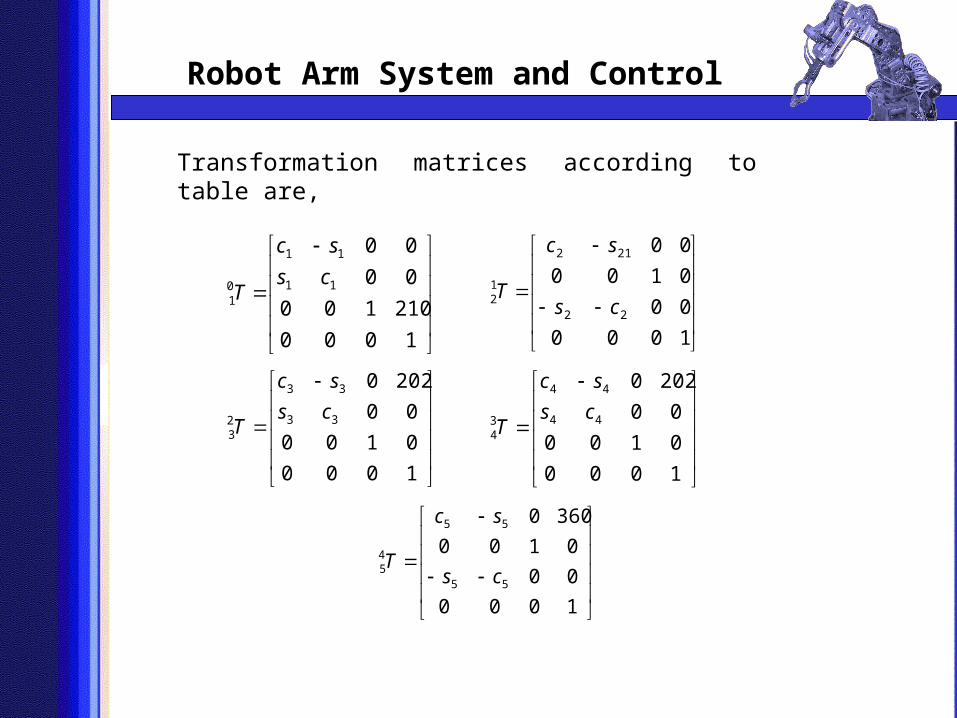
Transformation matrices according to table are,
1000
0100
00
2020
33
33
23
cs
sc
T
1000
0100
00
2020
44
44
34
cs
sc
T
1000
00
0100
3600
55
55
45 cs
sc
T
Robot Arm System and Control
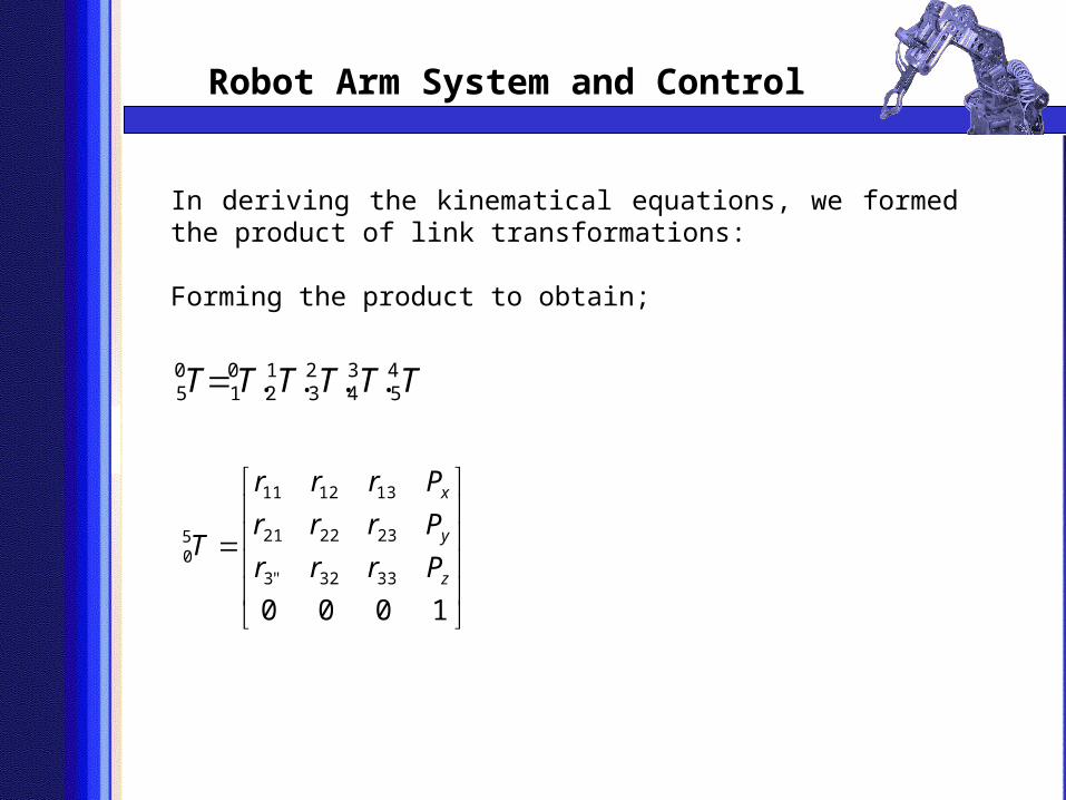
In deriving the kinematical equations, we formed the product of link transformations:
Forming the product to obtain;
50
10
21
32
43
54T T T T T T . . . .
10003332"3
232221
131211
50
z
y
x
Prrr
Prrr
Prrr
T

Robot Arm System and Control
Px , Py, Pz, can be found with respect to the angles θ1,2,3,4
After finding the solution matrices, program executes for choosing the best solution for the manipulator control. The criteria of choosing the best one are, searching the easiest and shortest movement of the manipulator.
In this study, the aim is obtaining a path control algorithm by using inverse kinematics method. As told before, by this method manipulator’s joints angles are determined from the required target given in Cartesian coordinates. And after these steps the main control program starts to execute by using joint base control algorithms.

Robot Arm System and Control
Before the path control applications, the position following capability of the manipulator is tested for each arm. First of all, reconsidering the mechanical design and its workspace; the possible motion capabilities of the manipulator are investigated. Joint based control is used for each joint by applying additional control algorithms. Responses of the joints for different control algorithms are tested.
Figure 2 Figure 3

Robot Arm System and Control
While planning a trajectory, first two or more points should be decided. By using inverse kinematics method these points can also be defined by angular positions of the arms.
Figure 4 Figure 5

Robot Arm System and Control
After defining these angles, the trajectory of a joint can be described by a polynomial equation as given below.
Θ(t)=a0 + a1 t + a2 t2 + a3 t
3
and the angular velocity can be defined as,
Θ’(t)= a1 + 2 a2 t + 3 a3 t2
.
If the coefficients can be determined correctly then the trajectory following will be possible.
After determining these coefficients, we can generate the control algorithm of the manipulator by applying the time depended angular velocity equation.

Robot Arm System and Control
.
As an example the trajectory and parameters of the manipulator are given in table below:
J0 J1 J2 J4
θ0=64.6 0 θ0=8.5 0 θ0= -5 0 θ0=57 0
θf=41.1 0 θf=8.8 0 θf=22.8 0 θf=58 0
Dθ=23.5 0 Dθ=-0.3 0 Dθ=27.8 0 Dθ=1 0
Dt=6.77 s Dt=0.05 s Dt=9.62 s Dt=0.27 s
Here Dθ represents the amount of the way that the manipulator takes among this trajectory, and also Dt represents the time that
the joint needs for reaching the end point. Dt can easily be
computed by the division of the (Dθ/ w) where w is in (0/s) format.
Table 2

Robot Arm System and Control
.
By this table, we can easily determine the needed time of the arms for whole trajectory. Since we want all joints to start and end their motions at the same time then we have to choose each joint a specific time value. After that, we can determine the angular velocities of the arms by using the equations which are formed via using Table 2.
Figure 6 Path for object A (in XY plane)
Figure 7 Path for object A (in XZ plane)
In this study there are two objects with their own placing points after picking from the conveyor band. Thus there are two paths determined for the manipulator and the path following features are observed for each of them. Results can be seen in figures below.

• After theoretical study, to test the performance of the presented algorithym, an application mechanism is prepared as shown before. During the tests, system classified 14 predefined objects in 500 times random taken photos of passing objects. In these tests, the 95% of the system decisions were right. And it is determined that most of the reasons of the faults were that the objects were far from the center of the conveyor band.
• Even there are a little data loss for the bigger objects in 14 classes, identification is realized whereas there were some problems (mentioned in 5% faults) for the smaller objects.
• In addition, when the noise in reduced data of the objects which are same in color with the conveyor band is homogenous, it doesn’t affect the identification algorithym; but if the noise is in the characteristic of damaging the region distrubition of any object, it causes errors for the algorithym.
• Improving the mechanical system of the conveyor system, performance of the software can be higher. Furthermore, with a conveyor band that has homogenous reflection coefficient distribution and is not swinging during moving the percentage of right identification can be improved,
Conclusion

•It is observed that, with its present design, manipulator is more favourable in pick and place operations. However, by adding a prismatic joint, manipulator will be more sensitive and smooth for two-dimensional motions.
•In addition, high reduction usage of the motion motors due to the limited sources has caused limited velocity adjustments, where it is necessary for smooth path control of the manipulator. Also the result of the low speed is observed when joints need high moments for path control. It is clear that usage of high capacity AC or DC servo-motors can prevent this problem.
•Again due to limited sources, multi-turn potentiometers are used for the measurement of the joint angles. And it is observed that the hysterisys of these potentiometers while the arms moves forward and backwards affect the smoothness and the repeatability features of the manipulator in negative way.
Conclusion


![arXiv:1602.00283v1 [math.AG] 31 Jan 2016 panaroma of the fundamental group of the modular orbifold A. Muhammed Uluda gand Ayberk Zeytin Department of Mathematics, Galatasaray University](https://img.pdfslide.us/doc/110x75/5ab14cec7f8b9a00728c24ac/arxiv160200283v1-mathag-31-jan-2016-panaroma-of-the-fundamental-group-of-the.jpg)