Embed Size (px)
Citation preview
By Patricia Carranza
Computer Engineering California Polytechnic State University, San Luis Obispo CPE 461 & 462 - Dr. John Oliver September 2015
1
Introduction .................................................................................................................................................. 3
Purpose ..................................................................................................................................................... 3
Background ............................................................................................................................................... 3
Functionality ............................................................................................................................................. 3
Technical Details ........................................................................................................................................... 4
System Requirements ............................................................................................................................... 4
System Specifications ................................................................................................................................ 4
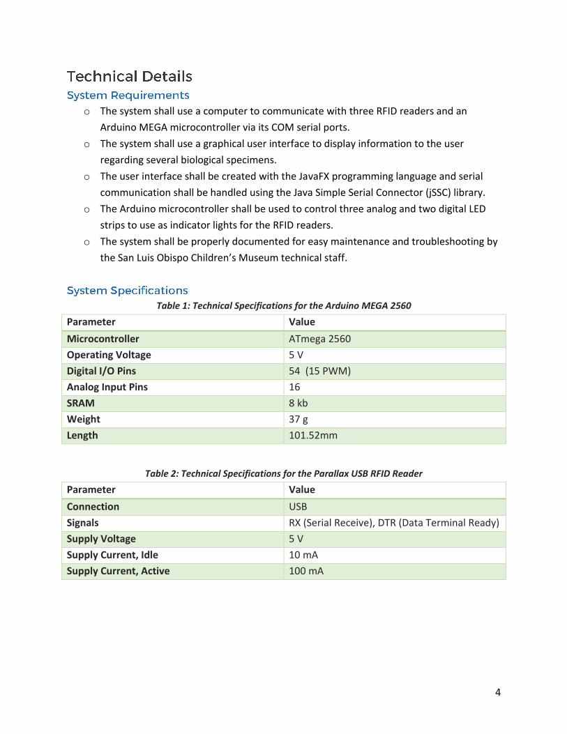
Table 1: Technical Specifications for the Arduino MEGA 2560 ............................................................ 4
Table 2: Technical Specifications for the Parallax USB RFID Reader ..................................................... 4
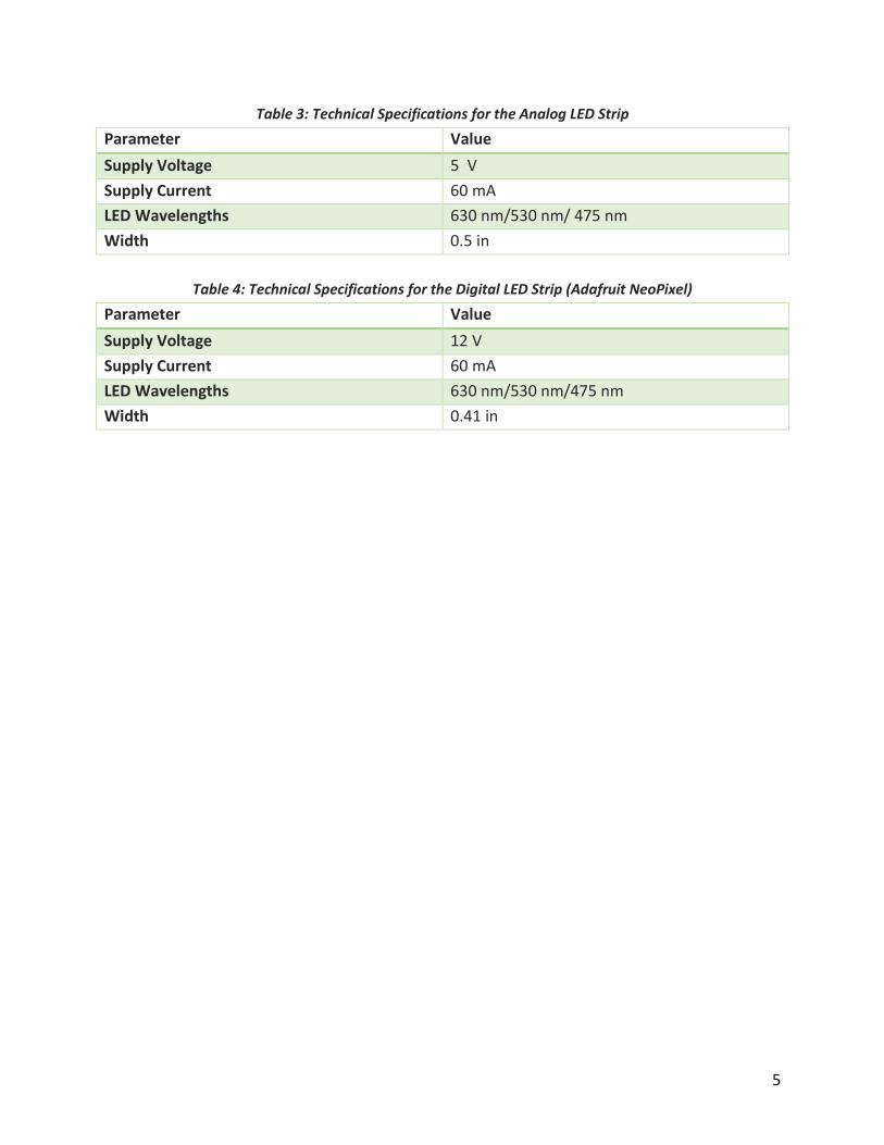
Table 3: Technical Specifications for the Analog LED Strip ................................................................... 5
Table 4: Technical Specifications for the Digital LED Strip (Adafruit NeoPixel) .................................... 5
System Architecture ...................................................................................................................................... 6
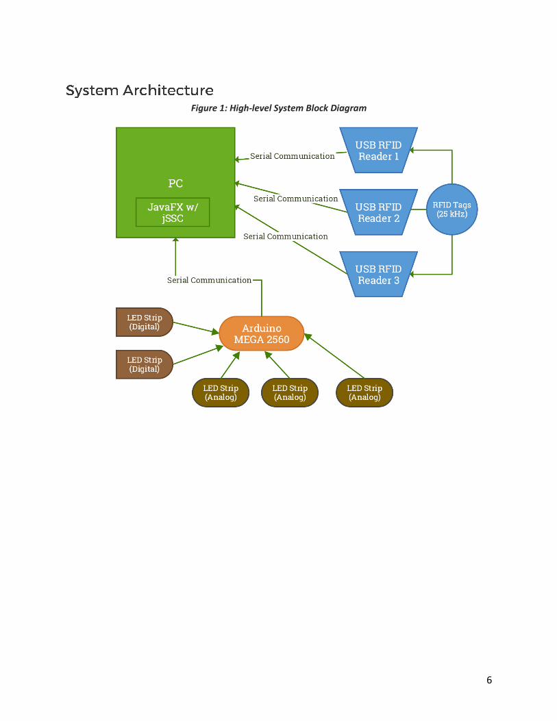
Figure 1: High-level System Block Diagram ........................................................................................... 6
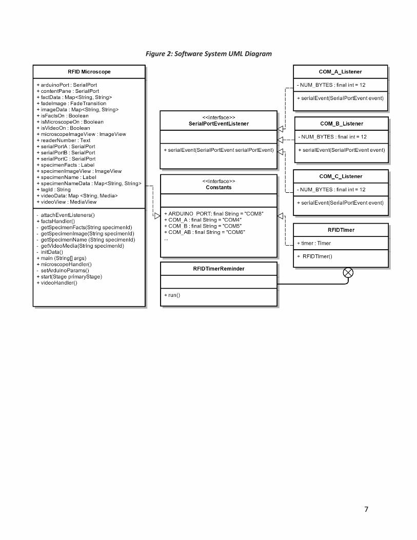
Figure 2: Software System UML Diagram ............................................................................................. 7
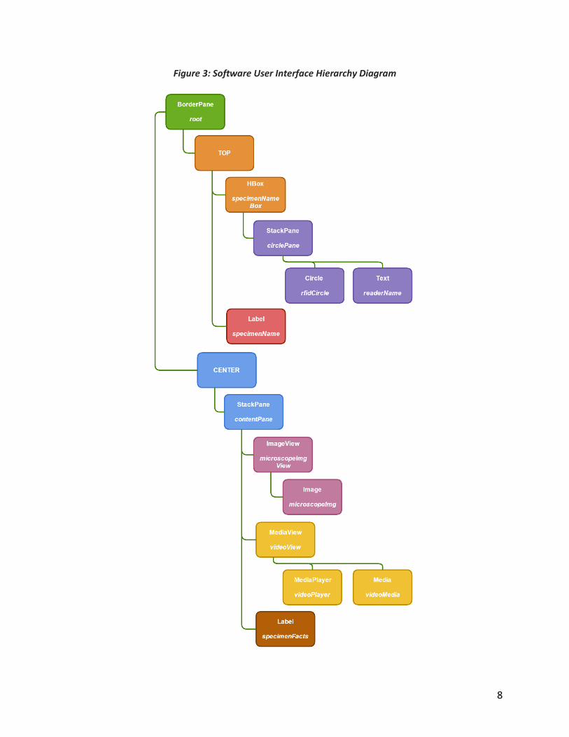
Figure 3: Software User Interface Hierarchy Diagram .......................................................................... 8
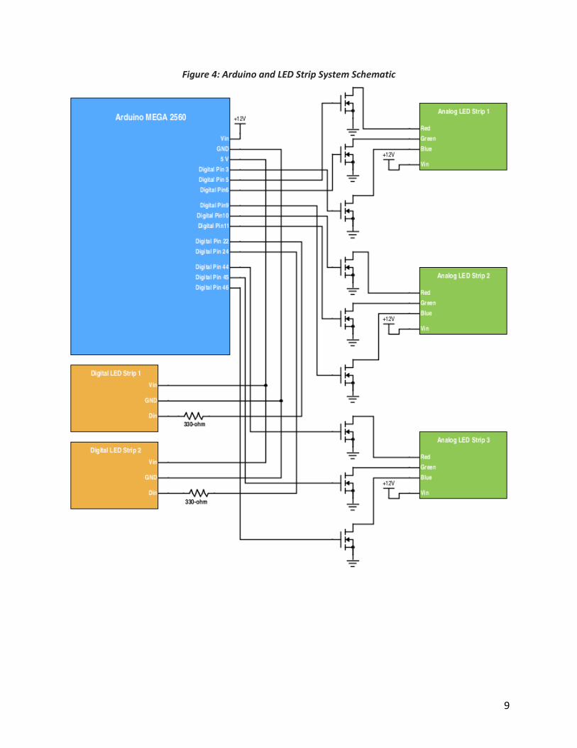
Figure 4: Arduino and LED Strip System Schematic .............................................................................. 9
Figure 5: Microcontroller/LED Strip Wiring Diagram .......................................................................... 10
Project Planning and Design ....................................................................................................................... 11
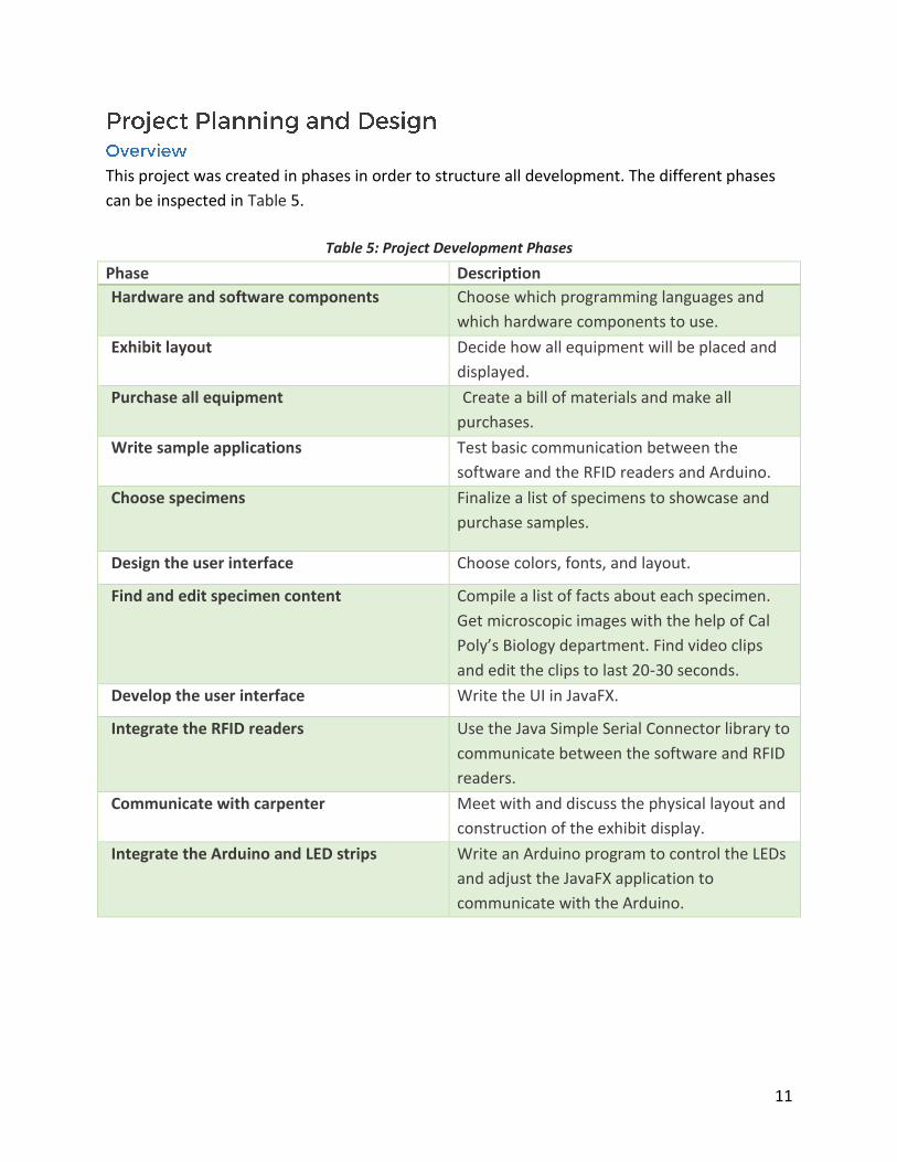
Overview ................................................................................................................................................. 11
Table 5: Project Development Phases ................................................................................................ 11
Hardware ................................................................................................................................................ 12
Software .................................................................................................................................................. 12
User Interface ......................................................................................................................................... 13
Figure 6: Initial UI Design .................................................................................................................... 14
Figure 7: Final UI Design ...................................................................................................................... 14
Content ................................................................................................................................................... 14
Table 6: List of Available Specimens ................................................................................................... 15
Exhibit Display ......................................................................................................................................... 17
Figure 8: User-facing Physical Layout ................................................................................................. 17
System Integration ...................................................................................................................................... 18
Writing the User Interface ...................................................................................................................... 18
2
Code Snippet 1: General format of a Runnable in JavaFX .................................................................. 18
Code Snippet 2: Equivalent Code Snippet 1 written as a lambda expression: ................................... 18
Setting up NetBeans with jSSC ................................................................................................................ 19
Communicating with the RFID readers ................................................................................................... 19
Table 7: RFID Reader USB Connection Specifications ......................................................................... 20
Code Snippet 3: Set up serial communication parameters ................................................................ 20
Communicating with the Arduino ........................................................................................................... 21
Table 8: Arduino Serial Connection Specifications ............................................................................. 21
Arduino Code and Component Structure ............................................................................................... 21
Table 9: Arduino Serial Commands ..................................................................................................... 21
Code Snippet 4: Setting Analog LED Strip Color .................................................................................. 22
Software Sequence ................................................................................................................................. 22
Figure 9: Software Timing Sequence .................................................................................................. 24
Conclusion ................................................................................................................................................... 25
Future Work ............................................................................................................................................ 25
Appendix ..................................................................................................................................................... 26
Appendix A - Parallax RFID Reader Datasheet ........................................................................................ 26
Appendix B - Parallax USB FTD Driver Link.............................................................................................. 26
Appendix C - Adafruit LED Strip Uber Guide ........................................................................................... 26
Appendix D - Link to jSSC GitHub Page ................................................................................................... 26
Appendix E - Adafruit NeoPixel Library GitHub Page .............................................................................. 26
Appendix F - Specimen Fact Sources ...................................................................................................... 26
Appendix G - Specimen Video Sources ................................................................................................... 28
Appendix H - Bill of Materials ................................................................................................................. 30
Appendix I - List of Specimen Facts ......................................................................................................... 31
Appendix J – Editing Specimen Content in NetBeans ............................................................................. 35
Appendix K - Arduino LED Strip Code ..................................................................................................... 37
3
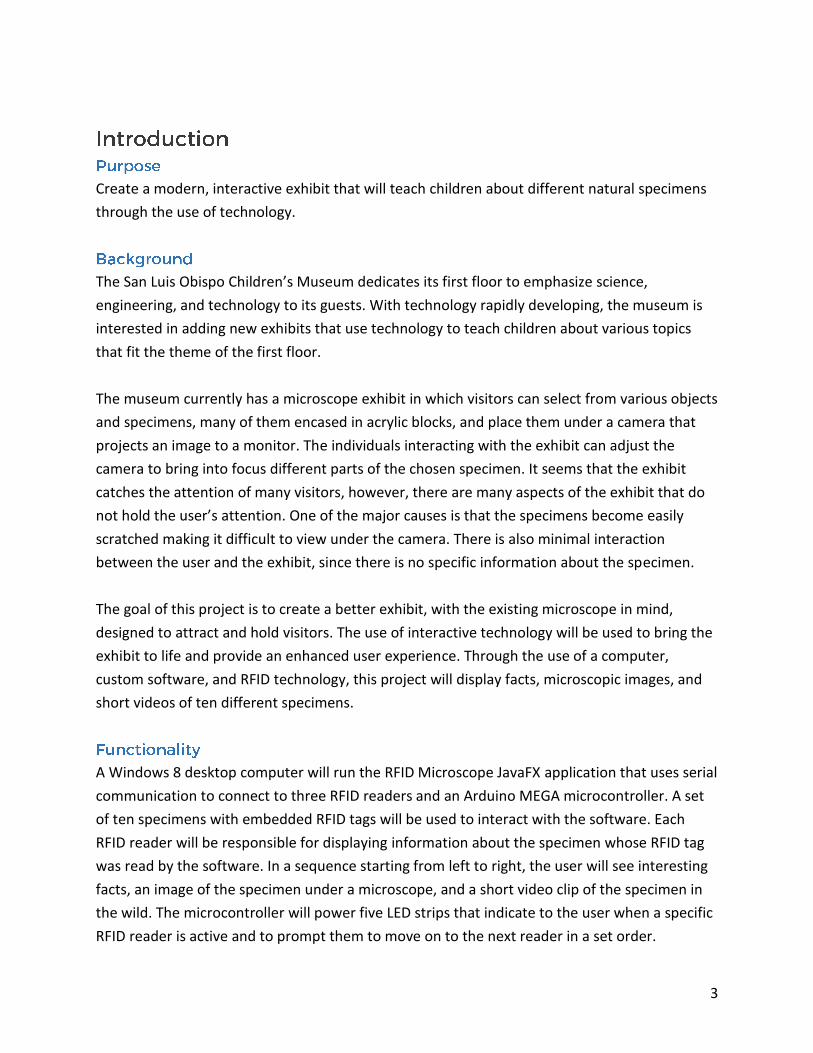
Create a modern, interactive exhibit that will teach children about different natural specimens
through the use of technology.
The San Luis Obispo Children’s Museum dedicates its first floor to emphasize science,
engineering, and technology to its guests. With technology rapidly developing, the museum is
interested in adding new exhibits that use technology to teach children about various topics
that fit the theme of the first floor.
The museum currently has a microscope exhibit in which visitors can select from various objects
and specimens, many of them encased in acrylic blocks, and place them under a camera that
projects an image to a monitor. The individuals interacting with the exhibit can adjust the
camera to bring into focus different parts of the chosen specimen. It seems that the exhibit
catches the attention of many visitors, however, there are many aspects of the exhibit that do
not hold the user’s attention. One of the major causes is that the specimens become easily
scratched making it difficult to view under the camera. There is also minimal interaction
between the user and the exhibit, since there is no specific information about the specimen.
The goal of this project is to create a better exhibit, with the existing microscope in mind,
designed to attract and hold visitors. The use of interactive technology will be used to bring the
exhibit to life and provide an enhanced user experience. Through the use of a computer,
custom software, and RFID technology, this project will display facts, microscopic images, and
short videos of ten different specimens.
A Windows 8 desktop computer will run the RFID Microscope JavaFX application that uses serial
communication to connect to three RFID readers and an Arduino MEGA microcontroller. A set
of ten specimens with embedded RFID tags will be used to interact with the software. Each
RFID reader will be responsible for displaying information about the specimen whose RFID tag
was read by the software. In a sequence starting from left to right, the user will see interesting
facts, an image of the specimen under a microscope, and a short video clip of the specimen in
the wild. The microcontroller will power five LED strips that indicate to the user when a specific
RFID reader is active and to prompt them to move on to the next reader in a set order.
4
o The system shall use a computer to communicate with three RFID readers and an
Arduino MEGA microcontroller via its COM serial ports.
o The system shall use a graphical user interface to display information to the user
regarding several biological specimens.
o The user interface shall be created with the JavaFX programming language and serial
communication shall be handled using the Java Simple Serial Connector (jSSC) library.
o The Arduino microcontroller shall be used to control three analog and two digital LED
strips to use as indicator lights for the RFID readers.
o The system shall be properly documented for easy maintenance and troubleshooting by
the San Luis Obispo Children’s Museum technical staff.
Table 1: Technical Specifications for the Arduino MEGA 2560
Parameter Value
Microcontroller ATmega 2560
Operating Voltage 5 V
Digital I/O Pins 54 (15 PWM)
Analog Input Pins 16
SRAM 8 kb
Weight 37 g
Length 101.52mm
Table 2: Technical Specifications for the Parallax USB RFID Reader
Parameter Value
Connection USB
Signals RX (Serial Receive), DTR (Data Terminal Ready)
Supply Voltage 5 V
Supply Current, Idle 10 mA
Supply Current, Active 100 mA
5
Table 3: Technical Specifications for the Analog LED Strip
Parameter Value
Supply Voltage 5 V
Supply Current 60 mA
LED Wavelengths 630 nm/530 nm/ 475 nm
Width 0.5 in
Table 4: Technical Specifications for the Digital LED Strip (Adafruit NeoPixel)
Parameter Value
Supply Voltage 12 V
Supply Current 60 mA
LED Wavelengths 630 nm/530 nm/475 nm
Width 0.41 in
6
Figure 1: High-level System Block Diagram
7
Figure 2: Software System UML Diagram
8
Figure 3: Software User Interface Hierarchy Diagram
9
Figure 4: Arduino and LED Strip System Schematic
10
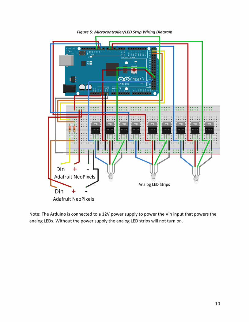
Figure 5: Microcontroller/LED Strip Wiring Diagram
Note: The Arduino is connected to a 12V power supply to power the Vin input that powers the
analog LEDs. Without the power supply the analog LED strips will not turn on.
11
This project was created in phases in order to structure all development. The different phases
can be inspected in Table 5.
Table 5: Project Development Phases
Phase Description
Hardware and software components Choose which programming languages and
which hardware components to use.
Exhibit layout Decide how all equipment will be placed and
displayed.
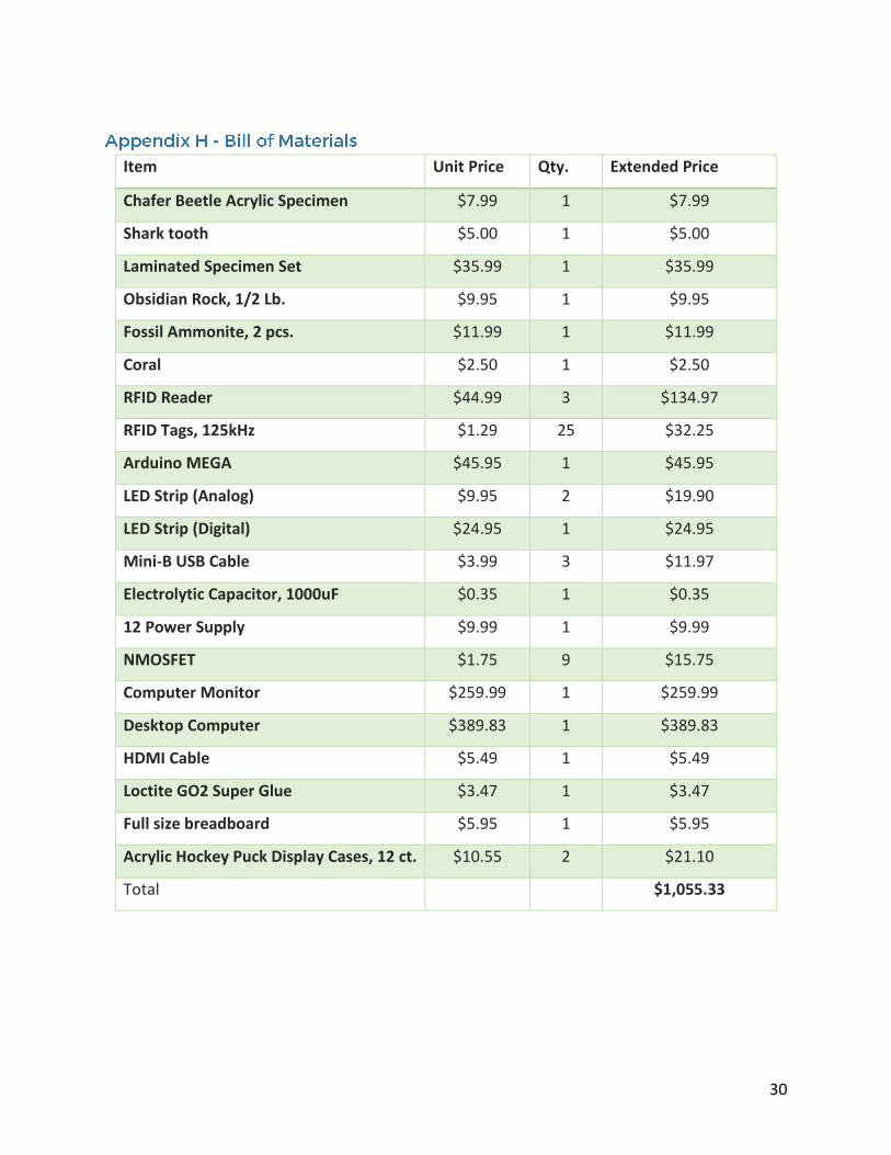
Purchase all equipment Create a bill of materials and make all
purchases.
Write sample applications Test basic communication between the
software and the RFID readers and Arduino.
Choose specimens
Finalize a list of specimens to showcase and
purchase samples.
Design the user interface Choose colors, fonts, and layout.
Find and edit specimen content Compile a list of facts about each specimen.
Get microscopic images with the help of Cal
Poly’s Biology department. Find video clips
and edit the clips to last 20-30 seconds.
Develop the user interface Write the UI in JavaFX.
Integrate the RFID readers Use the Java Simple Serial Connector library to
communicate between the software and RFID
readers.
Communicate with carpenter Meet with and discuss the physical layout and
construction of the exhibit display.
Integrate the Arduino and LED strips Write an Arduino program to control the LEDs
and adjust the JavaFX application to
communicate with the Arduino.

12
During the design process, there were three main considerations for the hardware component
setups:
1. Utilizing a Raspberry Pi to run the software and control the RFID readers and LED strips.
2. Using a computer to run the software and connect to an Arduino via serial
communication and have the Arduino control the RFID readers and LED strips.
3. Using a computer to run the software and control the RFID readers via serial
communication and communicate with an Arduino that would control the LED strips.
Ultimately, it was decided that option three fit the best combination of ease of development,
budget, and maintainability. Option one was ruled out first due to limitations in processing
power and memory of the Raspberry Pi, despite having the lowest budget. The software for this
project is very graphically intensive which requires better graphics and processing power to
avoid lag. Furthermore, learning to use a Raspberry Pi is more difficult for someone that has no
experience using one as opposed to using a desktop computer which would make it difficult to
maintain by the future museum technical staff.
Therefore, the next step was deciding whether to have the Arduino or the computer control the
RFID readers. The bulk of the functionality relies on communication between the RFID readers
and the computer, therefore, it made more sense to have the computer handle all
communication with the RFID readers. The Arduino is mostly used to give the user feedback,
but is not necessary for the project to function. If the Arduino were to fail for any reason the
rest of the software would still be functional and useable.
One of the main goals of this project is to allow a museum staff member with a bit of technical
knowledge to easily maintain and troubleshoot the exhibit. Given this environment it is
essential that a staff member be able to make small adjustments to specimen facts, images, and
videos as well as add new RFID tag ID’s in case one is lost or broken. With this in mind, this
project uses a Windows desktop computer to run the software and connect all of the essential
hardware via USB.
When deciding which programming language to use it was important that the language be able
to easily support styling and serial communication. After researching available languages and
libraries the two main options were:
1. JavaFX & CSS
2. Python & Qt

13
After researching a bit more it became clear that there is more documentation and examples
available for creating visually appealing applications with JavaFX than for Python. It was also an
added bonus that Cascading Style Sheet (CSS) styling was available with JavaFX.
After deciding on JavaFX as the programming language for the software application the next
important step was deciding which Java serial communication library to integrate. The two
main options are the RXTX library and the Java Simple Serial Connector (jSSC) library. RXTX has
been around longer than jSSC, however, RXTX is not being actively maintained and the code is
not open-sourced. In contrast, jSSC is actively maintained and is open-sourced, therefore, jSSC
is used in this project. The source code for the project is being hosted on GitHub and
maintained by user scream3r. See Appendix D for a link to the GitHub page that includes the
most recent release, source code, and documentation for the library. The library has gained
popularity and there are various examples and Q&A forums readily available that make it easy
to get started and get help if needed.
In order to make development a bit faster, the Netbeans IDE is used in this project. The IDE
makes it easier to build and test the application, as well as, make it easy to package the finished
application as an installer that creates an executable on the computer.
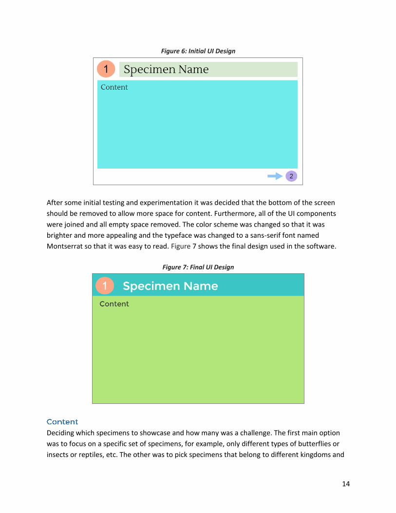
The main goal for the user interface (UI) was to create a design that was bright, appealing, and
easy to read while providing only the necessary information. Figure 6 shows the initial UI design
proposed for this project. The orange circle on the top left is intended to show which RFID
reader is currently active and the design prominently displays the name of the specimen being
viewed. Most of the screen real-estate is left for the specimen content (facts, images, and
videos) while the bottom is used to prompt the user to continue the necessary sequence.
14
Figure 6: Initial UI Design
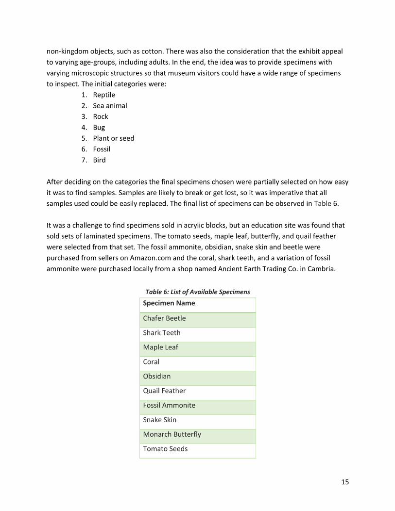
After some initial testing and experimentation it was decided that the bottom of the screen
should be removed to allow more space for content. Furthermore, all of the UI components
were joined and all empty space removed. The color scheme was changed so that it was
brighter and more appealing and the typeface was changed to a sans-serif font named
Montserrat so that it was easy to read. Figure 7 shows the final design used in the software.
Figure 7: Final UI Design
Deciding which specimens to showcase and how many was a challenge. The first main option
was to focus on a specific set of specimens, for example, only different types of butterflies or
insects or reptiles, etc. The other was to pick specimens that belong to different kingdoms and
15
non-kingdom objects, such as cotton. There was also the consideration that the exhibit appeal
to varying age-groups, including adults. In the end, the idea was to provide specimens with
varying microscopic structures so that museum visitors could have a wide range of specimens
to inspect. The initial categories were:
1. Reptile
2. Sea animal
3. Rock
4. Bug
5. Plant or seed
6. Fossil
7. Bird
After deciding on the categories the final specimens chosen were partially selected on how easy
it was to find samples. Samples are likely to break or get lost, so it was imperative that all
samples used could be easily replaced. The final list of specimens can be observed in Table 6.
It was a challenge to find specimens sold in acrylic blocks, but an education site was found that
sold sets of laminated specimens. The tomato seeds, maple leaf, butterfly, and quail feather
were selected from that set. The fossil ammonite, obsidian, snake skin and beetle were
purchased from sellers on Amazon.com and the coral, shark teeth, and a variation of fossil
ammonite were purchased locally from a shop named Ancient Earth Trading Co. in Cambria.
Table 6: List of Available Specimens
Specimen Name
Chafer Beetle
Shark Teeth
Maple Leaf
Coral
Obsidian
Quail Feather
Fossil Ammonite
Snake Skin
Monarch Butterfly
Tomato Seeds

16
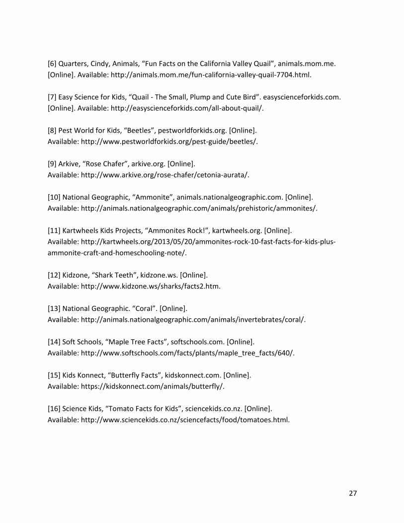
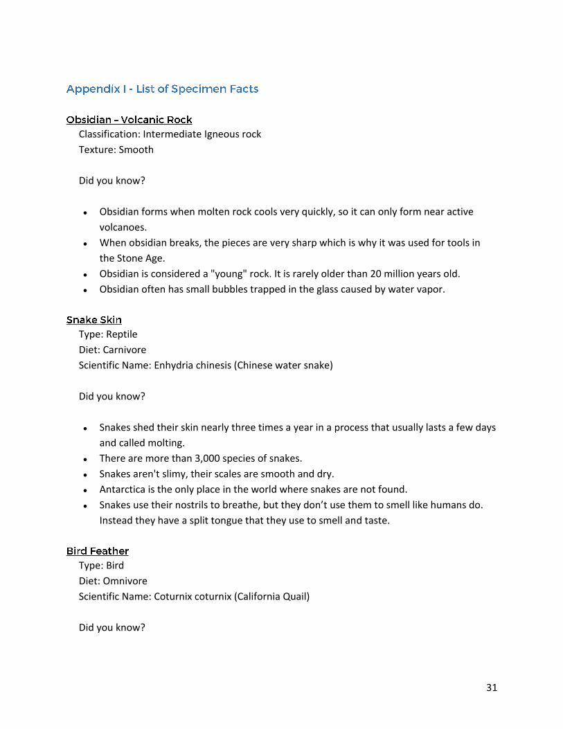
The interesting facts used for each specimen were mostly located from various online sites that
focused on teaching children, such as: National Geographic, Kids Konnect, Soft Schools and
Science Kids. The full list of facts and sources can be found in Appendix I and Appendix F,
respectively. The layout of the text in the user interface was organized in a way that was
consistent and structured by including every specimen’s name, type, and diet above the facts.
The main goal for the facts was to include a combination of quirky, interesting facts that are fun
to read and other facts that are essential to know about the type of specimen.
The images of the specimens under a microscope are mostly original pictures taken with the
help of Cal Poly’s Biology Department (a special Thank You to Doug Brewster and Michael Curto
for the help). Initially, most pictures were obtained from the internet, but it made more sense
for users to view a close-up image of the actual sample they are currently holding. Only the
coral and tomato seed images were downloaded from the internet.
The video content has a mixture of themes. Generally, the goal was to capture the essence of
the specimen and show it as it would act in the wild or show how it evolves over time. For
example, the butterfly clip shows how a butterfly starts as a caterpillar and then transforms
itself when it emerges from its cocoon. Other videos, like the obsidian video, focuses on
volcanic rock in general, how a volcano erupts and how lava flows and cools.
After taking into consideration the attention spans of children, it was determined that the
length of each video would be about thirty seconds. This was deemed a good length since it
provides enough time to show progression throughout the clip while preventing any dull
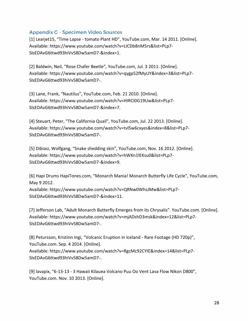
moments. All of the final video clips are edited versions of videos found on video sites Vimeo
and YouTube. The full list of video sources can be found in Appendix G.
17
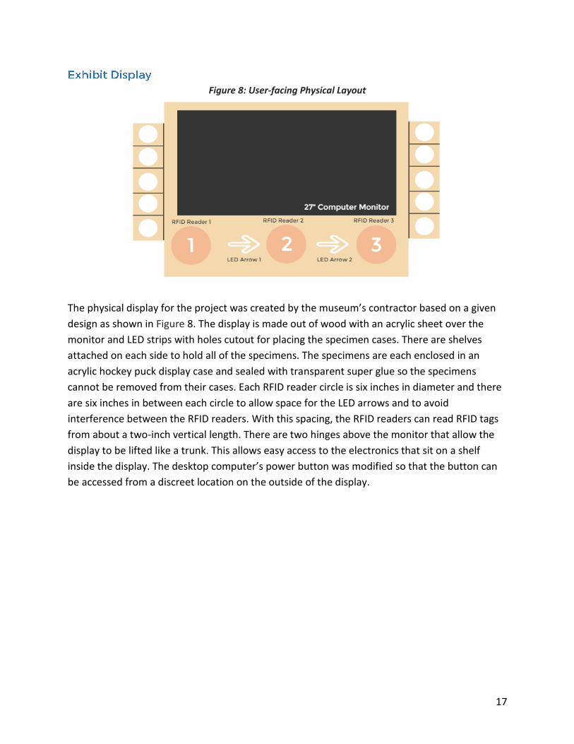
Figure 8: User-facing Physical Layout
The physical display for the project was created by the museum’s contractor based on a given
design as shown in Figure 8. The display is made out of wood with an acrylic sheet over the
monitor and LED strips with holes cutout for placing the specimen cases. There are shelves
attached on each side to hold all of the specimens. The specimens are each enclosed in an
acrylic hockey puck display case and sealed with transparent super glue so the specimens
cannot be removed from their cases. Each RFID reader circle is six inches in diameter and there
are six inches in between each circle to allow space for the LED arrows and to avoid
interference between the RFID readers. With this spacing, the RFID readers can read RFID tags
from about a two-inch vertical length. There are two hinges above the monitor that allow the
display to be lifted like a trunk. This allows easy access to the electronics that sit on a shelf
inside the display. The desktop computer’s power button was modified so that the button can
be accessed from a discreet location on the outside of the display.
18
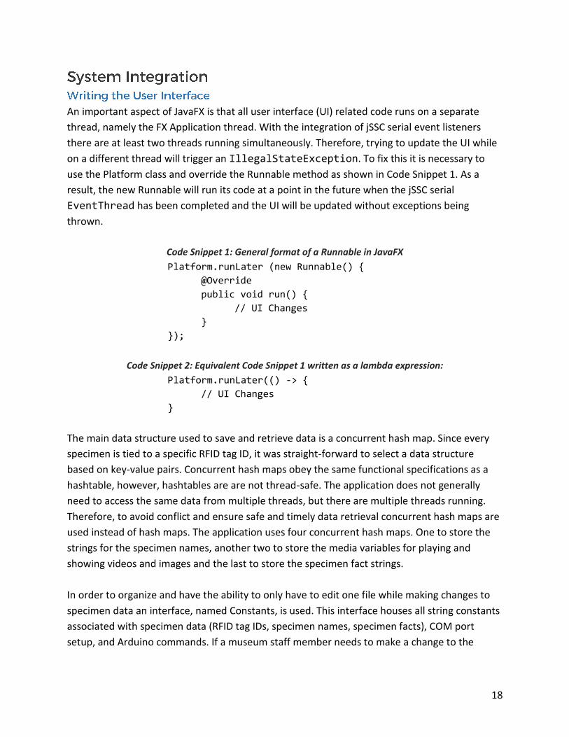
An important aspect of JavaFX is that all user interface (UI) related code runs on a separate
thread, namely the FX Application thread. With the integration of jSSC serial event listeners
there are at least two threads running simultaneously. Therefore, trying to update the UI while
on a different thread will trigger an IllegalStateException. To fix this it is necessary to
use the Platform class and override the Runnable method as shown in Code Snippet 1. As a
result, the new Runnable will run its code at a point in the future when the jSSC serial
EventThread has been completed and the UI will be updated without exceptions being
thrown.
Code Snippet 1: General format of a Runnable in JavaFX
Platform.runLater (new Runnable() {
@Override
public void run() {
// UI Changes
}
});
Code Snippet 2: Equivalent Code Snippet 1 written as a lambda expression:
Platform.runLater(() -> {
// UI Changes
}
The main data structure used to save and retrieve data is a concurrent hash map. Since every
specimen is tied to a specific RFID tag ID, it was straight-forward to select a data structure
based on key-value pairs. Concurrent hash maps obey the same functional specifications as a
hashtable, however, hashtables are are not thread-safe. The application does not generally
need to access the same data from multiple threads, but there are multiple threads running.
Therefore, to avoid conflict and ensure safe and timely data retrieval concurrent hash maps are
used instead of hash maps. The application uses four concurrent hash maps. One to store the
strings for the specimen names, another two to store the media variables for playing and
showing videos and images and the last to store the specimen fact strings.
In order to organize and have the ability to only have to edit one file while making changes to
specimen data an interface, named Constants, is used. This interface houses all string constants
associated with specimen data (RFID tag IDs, specimen names, specimen facts), COM port
setup, and Arduino commands. If a museum staff member needs to make a change to the
19
specimen data, image or video file paths, or RFID readers they would only need to edit this file
and rebuild the project in the Netbeans IDE.
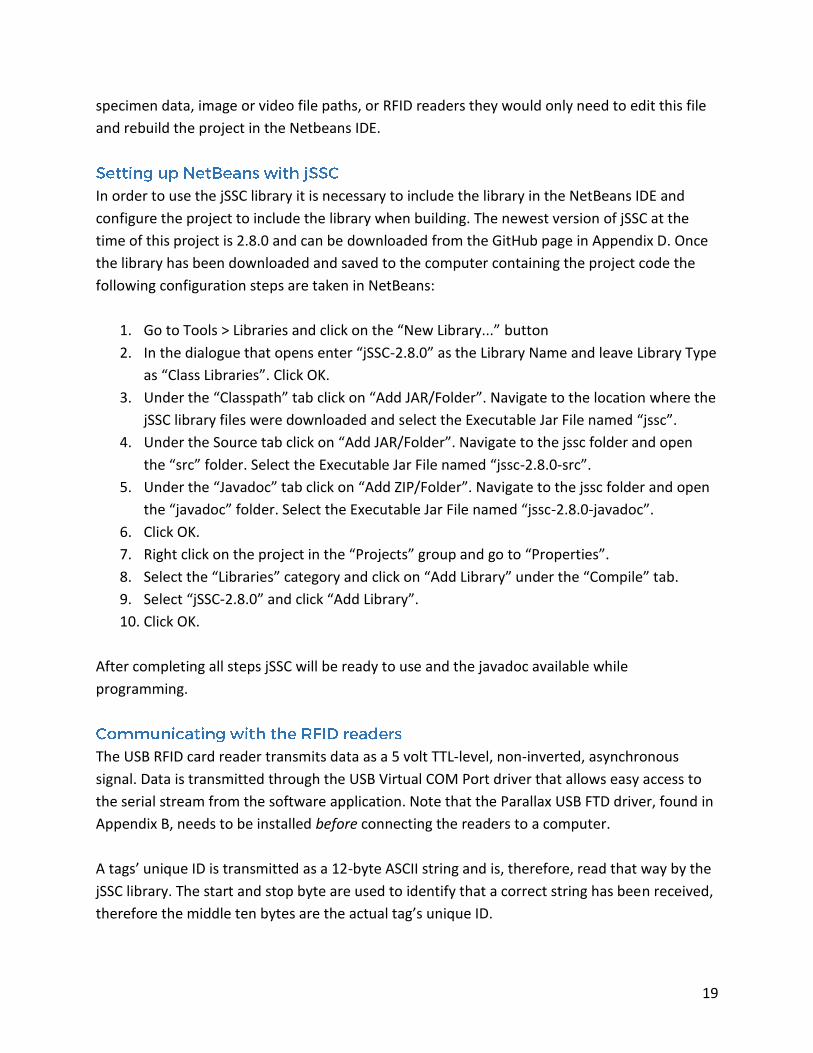
In order to use the jSSC library it is necessary to include the library in the NetBeans IDE and
configure the project to include the library when building. The newest version of jSSC at the
time of this project is 2.8.0 and can be downloaded from the GitHub page in Appendix D. Once
the library has been downloaded and saved to the computer containing the project code the
following configuration steps are taken in NetBeans:
1. Go to Tools > Libraries and click on the “New Library...” button
2. In the dialogue that opens enter “jSSC-2.8.0” as the Library Name and leave Library Type
as “Class Libraries”. Click OK.
3. Under the “Classpath” tab click on “Add JAR/Folder”. Navigate to the location where the
jSSC library files were downloaded and select the Executable Jar File named “jssc”.
4. Under the Source tab click on “Add JAR/Folder”. Navigate to the jssc folder and open
the “src” folder. Select the Executable Jar File named “jssc-2.8.0-src”.
5. Under the “Javadoc” tab click on “Add ZIP/Folder”. Navigate to the jssc folder and open
the “javadoc” folder. Select the Executable Jar File named “jssc-2.8.0-javadoc”.
6. Click OK.
7. Right click on the project in the “Projects” group and go to “Properties”.
8. Select the “Libraries” category and click on “Add Library” under the “Compile” tab.
9. Select “jSSC-2.8.0” and click “Add Library”.
10. Click OK.
After completing all steps jSSC will be ready to use and the javadoc available while
programming.
The USB RFID card reader transmits data as a 5 volt TTL-level, non-inverted, asynchronous
signal. Data is transmitted through the USB Virtual COM Port driver that allows easy access to
the serial stream from the software application. Note that the Parallax USB FTD driver, found in
Appendix B, needs to be installed before connecting the readers to a computer.
A tags’ unique ID is transmitted as a 12-byte ASCII string and is, therefore, read that way by the
jSSC library. The start and stop byte are used to identify that a correct string has been received,
therefore the middle ten bytes are the actual tag’s unique ID.
20
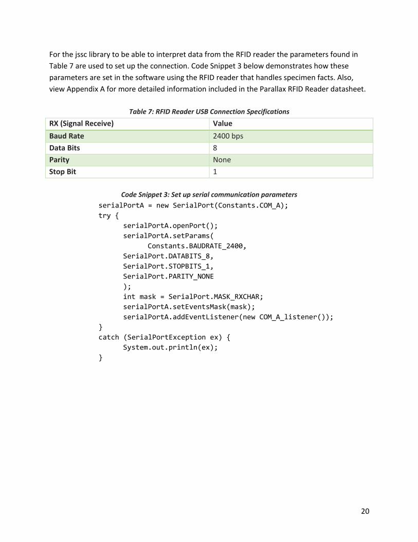
For the jssc library to be able to interpret data from the RFID reader the parameters found in
Table 7 are used to set up the connection. Code Snippet 3 below demonstrates how these
parameters are set in the software using the RFID reader that handles specimen facts. Also,
view Appendix A for more detailed information included in the Parallax RFID Reader datasheet.
Table 7: RFID Reader USB Connection Specifications
RX (Signal Receive) Value
Baud Rate 2400 bps
Data Bits 8
Parity None
Stop Bit 1
Code Snippet 3: Set up serial communication parameters
serialPortA = new SerialPort(Constants.COM_A);
try {
serialPortA.openPort();
serialPortA.setParams(
Constants.BAUDRATE_2400,
SerialPort.DATABITS_8,
SerialPort.STOPBITS_1,
SerialPort.PARITY_NONE
);
int mask = SerialPort.MASK_RXCHAR;
serialPortA.setEventsMask(mask);
serialPortA.addEventListener(new COM_A_listener());
}
catch (SerialPortException ex) {
System.out.println(ex);
}
21
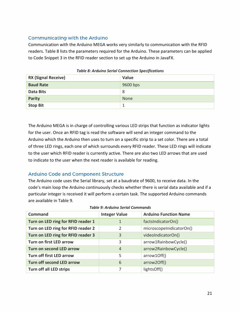
Communication with the Arduino MEGA works very similarly to communication with the RFID
readers. Table 8 lists the parameters required for the Arduino. These parameters can be applied
to Code Snippet 3 in the RFID reader section to set up the Arduino in JavaFX.
Table 8: Arduino Serial Connection Specifications
RX (Signal Receive) Value
Baud Rate 9600 bps
Data Bits 8
Parity None
Stop Bit 1
The Arduino MEGA is in charge of controlling various LED strips that function as indicator lights
for the user. Once an RFID tag is read the software will send an integer command to the
Arduino which the Arduino then uses to turn on a specific strip to a set color. There are a total
of three LED rings, each one of which surrounds every RFID reader. These LED rings will indicate
to the user which RFID reader is currently active. There are also two LED arrows that are used
to indicate to the user when the next reader is available for reading.
The Arduino code uses the Serial library, set at a baudrate of 9600, to receive data. In the
code’s main loop the Arduino continuously checks whether there is serial data available and if a
particular integer is received it will perform a certain task. The supported Arduino commands
are available in Table 9.
Table 9: Arduino Serial Commands
Command Integer Value Arduino Function Name
Turn on LED ring for RFID reader 1 1 factsIndicatorOn()
Turn on LED ring for RFID reader 2 2 microscopeInidicatorOn()
Turn on LED ring for RFID reader 3 3 videoIndicatorOn()
Turn on first LED arrow 3 arrow1RainbowCycle()
Turn on second LED arrow 4 arrow2RainbowCycle()
Turn off first LED arrow 5 arrow1Off()
Turn off second LED arrow 6 arrow2Off()
Turn off all LED strips 7 lightsOff()
22
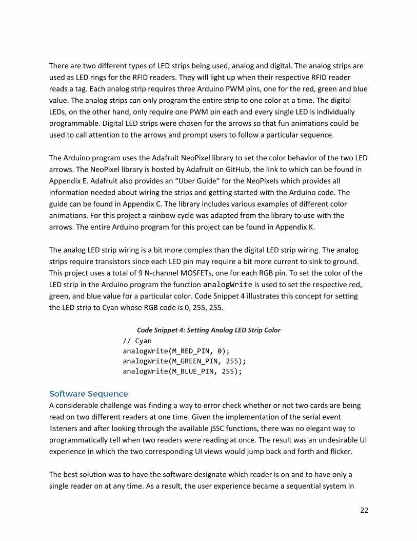
There are two different types of LED strips being used, analog and digital. The analog strips are
used as LED rings for the RFID readers. They will light up when their respective RFID reader
reads a tag. Each analog strip requires three Arduino PWM pins, one for the red, green and blue
value. The analog strips can only program the entire strip to one color at a time. The digital
LEDs, on the other hand, only require one PWM pin each and every single LED is individually
programmable. Digital LED strips were chosen for the arrows so that fun animations could be
used to call attention to the arrows and prompt users to follow a particular sequence.
The Arduino program uses the Adafruit NeoPixel library to set the color behavior of the two LED
arrows. The NeoPixel library is hosted by Adafruit on GitHub, the link to which can be found in
Appendix E. Adafruit also provides an “Uber Guide” for the NeoPixels which provides all
information needed about wiring the strips and getting started with the Arduino code. The
guide can be found in Appendix C. The library includes various examples of different color
animations. For this project a rainbow cycle was adapted from the library to use with the
arrows. The entire Arduino program for this project can be found in Appendix K.
The analog LED strip wiring is a bit more complex than the digital LED strip wiring. The analog
strips require transistors since each LED pin may require a bit more current to sink to ground.
This project uses a total of 9 N-channel MOSFETs, one for each RGB pin. To set the color of the
LED strip in the Arduino program the function analogWrite is used to set the respective red,
green, and blue value for a particular color. Code Snippet 4 illustrates this concept for setting
the LED strip to Cyan whose RGB code is 0, 255, 255.
Code Snippet 4: Setting Analog LED Strip Color
// Cyan
analogWrite(M_RED_PIN, 0);
analogWrite(M_GREEN_PIN, 255);
analogWrite(M_BLUE_PIN, 255);
A considerable challenge was finding a way to error check whether or not two cards are being
read on two different readers at one time. Given the implementation of the serial event
listeners and after looking through the available jSSC functions, there was no elegant way to
programmatically tell when two readers were reading at once. The result was an undesirable UI
experience in which the two corresponding UI views would jump back and forth and flicker.
The best solution was to have the software designate which reader is on and to have only a
single reader on at any time. As a result, the user experience became a sequential system in
23
which the software prompts the user to follow a certain order. At first this was seen as a
drawback to the user experience, but given the setting in which this exhibit will be used the
sequential order became a positive. Since where will be younger children that will experience
the exhibit it will be easier for them to have a logical order and instructions to follow.
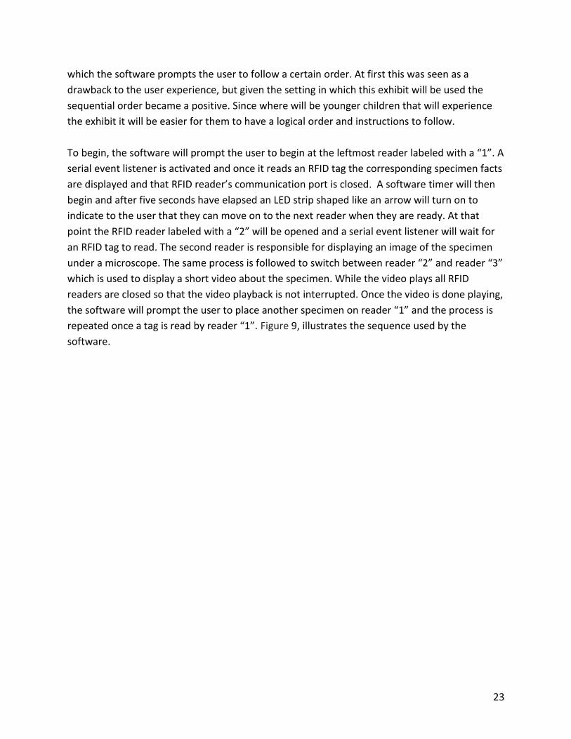
To begin, the software will prompt the user to begin at the leftmost reader labeled with a “1”. A
serial event listener is activated and once it reads an RFID tag the corresponding specimen facts
are displayed and that RFID reader’s communication port is closed. A software timer will then
begin and after five seconds have elapsed an LED strip shaped like an arrow will turn on to
indicate to the user that they can move on to the next reader when they are ready. At that
point the RFID reader labeled with a “2” will be opened and a serial event listener will wait for
an RFID tag to read. The second reader is responsible for displaying an image of the specimen
under a microscope. The same process is followed to switch between reader “2” and reader “3”
which is used to display a short video about the specimen. While the video plays all RFID
readers are closed so that the video playback is not interrupted. Once the video is done playing,
the software will prompt the user to place another specimen on reader “1” and the process is
repeated once a tag is read by reader “1”. Figure 9, illustrates the sequence used by the
software.
24
Figure 9: Software Timing Sequence
25
Overall, this was a very fun project to work on. It contained a very nice balance between
utilizing hardware and software components which is perfect for computer engineering. Like
usual there were certain frustrations when the software or hardware did not function as
expected, but all of those frustrations led to an enhanced understanding about every
component and about how programming languages work.
The finished result of this project ended up being better than expected and the hope is that the
same enthusiasm will be shared by the many visitors of the San Luis Obispo Children’s Museum.
With maintainability in mind, it would be great to also have a separate application that would
work as a utility for the RFID Microscope. This application could be used to connect to a
database that would contain all information about a specimen. Then, through this utility
specimens could be changed without having to directly edit and rebuild the code every time
any part of a specimen’s data is adjusted. This would make it easy for any member of the staff
to easily edit the project and be able to create special events. For example, if it is butterfly
month at the museum the project could be edited to showcase and teach about different types
of butterflies.
26
Parallax Inc., “RFID Card Reader, USB (#28340)”, USB RFID Reader datasheet, Oct. 2014 [Version
2.3].
Parallax Inc., “Parallax USB Driver Installer”, parallax.com, Jul. 2014. [Online].
Available: https://www.parallax.com/downloads/parallax-usb-driver-installer.
Burgess, Phillip, “Adafruit NeoPixel Uberguide”, Adafruit Industries, Jul. 2015.
Sokolov, Alexey (scream3r), “Java Simple Serial Connector”, github.com, Jan. 2014. [Online].
Available: https://github.com/scream3r/java-simple-serial-connector.
Adafruit Industries, “Adafruit NeoPixel Library”, github.com, Aug. 2015. [Online].
Available: https://github.com/adafruit/Adafruit_NeoPixel.
[1] Soft Schools, “Obsidian Rock Facts”, softschools.com. [Online].
Available: http://www.softschools.com/facts/rocks/obsidian_rock_facts/372/.
[2] Miller, Jim, Oregon State University, “Obsidian Is Hot Stuff”, oregonstate.edu. [Online].
Available: http://volcano.oregonstate.edu/obsidian.
[3] University College London, “Obsidian”, ucl.ac.uk. [Online].
Available: https://www.ucl.ac.uk/earth-
sciences/impact/geology/london/glossary/rocks/igneous/obsidian.
[4] Science Kids, “Fun Snake Facts for Kids”, sciencekids.co.nz. [Online].
Available: http://www.sciencekids.co.nz/sciencefacts/animals/snake.html.
[5] Bradford, Alina, Live Science, “Snake Facts & Types of Snakes”, livescience.com, Jun. 2014.
[Online]. Available: http://www.livescience.com/27845-snakes.html.
27
[6] Quarters, Cindy, Animals, “Fun Facts on the California Valley Quail”, animals.mom.me.
[Online]. Available: http://animals.mom.me/fun-california-valley-quail-7704.html.
[7] Easy Science for Kids, “Quail - The Small, Plump and Cute Bird”. easyscienceforkids.com.
[Online]. Available: http://easyscienceforkids.com/all-about-quail/.
[8] Pest World for Kids, “Beetles”, pestworldforkids.org. [Online].
Available: http://www.pestworldforkids.org/pest-guide/beetles/.
[9] Arkive, “Rose Chafer”, arkive.org. [Online].
Available: http://www.arkive.org/rose-chafer/cetonia-aurata/.
[10] National Geographic, “Ammonite”, animals.nationalgeographic.com. [Online].
Available: http://animals.nationalgeographic.com/animals/prehistoric/ammonites/.
[11] Kartwheels Kids Projects, “Ammonites Rock!”, kartwheels.org. [Online].
Available: http://kartwheels.org/2013/05/20/ammonites-rock-10-fast-facts-for-kids-plus-
ammonite-craft-and-homeschooling-note/.
[12] Kidzone, “Shark Teeth”, kidzone.ws. [Online].
Available: http://www.kidzone.ws/sharks/facts2.htm.
[13] National Geographic. “Coral”. [Online].
Available: http://animals.nationalgeographic.com/animals/invertebrates/coral/.
[14] Soft Schools, “Maple Tree Facts”, softschools.com. [Online].
Available: http://www.softschools.com/facts/plants/maple_tree_facts/640/.
[15] Kids Konnect, “Butterfly Facts”, kidskonnect.com. [Online].
Available: https://kidskonnect.com/animals/butterfly/.
[16] Science Kids, “Tomato Facts for Kids”, sciencekids.co.nz. [Online].
Available: http://www.sciencekids.co.nz/sciencefacts/food/tomatoes.html.
28
[1] Learjet15, “Time Lapse - tomato Plant HD”, YouTube.com, Mar. 14 2011. [Online].
Available: https://www.youtube.com/watch?v=LICDb8nM5rs&list=PLp7-
SlsEDAvG6ttwd93hiVv58Dw5amD7-&index=1.
[2] Baldwin, Neil, “Rose Chafer Beetle”, YouTube.com, Jul. 3 2011. [Online].
Available: https://www.youtube.com/watch?v=qygp52fMyUY&index=3&list=PLp7-
SlsEDAvG6ttwd93hiVv58Dw5amD7-.
[3] Lane, Frank, “Nautilus”, YouTube.com, Feb. 21 2010. [Online].
Available: https://www.youtube.com/watch?v=HIRCI0G19Uw&list=PLp7-
SlsEDAvG6ttwd93hiVv58Dw5amD7-&index=7.
[4] Steuart, Peter, “The California Quail”, YouTube.com, Jul. 22 2013. [Online].
Available: https://www.youtube.com/watch?v=tvl5w6cxyes&index=8&list=PLp7-
SlsEDAvG6ttwd93hiVv58Dw5amD7-.
[5] Dibiasi, Wolfgang, “Snake shedding skin”, YouTube.com, Nov. 16 2012. [Online].
Available: https://www.youtube.com/watch?v=hWXn1lEKsu0&list=PLp7-
SlsEDAvG6ttwd93hiVv58Dw5amD7-&index=9.
[6] Hapi Drums HapiTones.com, “Monarch Mania! Monarch Butterfly Life Cycle”, YouTube.com,
May 9 2012.
Available: https://www.youtube.com/watch?v=QRNw0WhsJMw&list=PLp7-
SlsEDAvG6ttwd93hiVv58Dw5amD7-&index=11.
[7] Jefferson Lab, “Adult Monarch Butterfly Emerges from its Chrysalis”. YouTube.com. [Online].
Available: https://www.youtube.com/watch?v=mjADshD3msk&index=12&list=PLp7-
SlsEDAvG6ttwd93hiVv58Dw5amD7-.
[8] Petursson, Kristinn Ingi, “Volcanic Eruption in Iceland - Rare Footage (HD 720p)”,
YouTube.com. Sep. 4 2014. [Online].
Available: https://www.youtube.com/watch?v=RgcMc92CYIE&index=14&list=PLp7-
SlsEDAvG6ttwd93hiVv58Dw5amD7-.
[9] lavapix, “6-13-13 - 3 Hawaii Kilauea Volcano Puu Oo Vent Lava Flow Nikon D800”,
YouTube.com. Nov. 10 2013. [Online].

29
Available: https://www.youtube.com/watch?v=Q8NXO6YxBmU&list=PLp7-
SlsEDAvG6ttwd93hiVv58Dw5amD7-&index=15.
[10] Volcano News, “Spectacular volcanic eruption at Batu Tara volcano, Indonesia”,
YouTube.com. Jul. 7 2015. [Online].
Available: https://www.youtube.com/watch?v=CsA05jdCj0M&index=16&list=PLp7-
SlsEDAvG6ttwd93hiVv58Dw5amD7-.
[11] Growing Wisdom, “How to choose a Japanese Maple such as Fire Glow & Autumn Moon!”,
YouTube.com. May 8 2013. [Online].
Available: https://www.youtube.com/watch?v=_FSc_nnbD2c&index=17&list=PLp7-
SlsEDAvG6ttwd93hiVv58Dw5amD7-.
[12] Va.Le Cinematografica 78, “Ocean life: Coral Reef”, Vimeo.com, Mar. 22 2010. [Online].
Available: https://vimeo.com/10355054.
[13] DPG Productions. “DPG Originals: Confronting Sharks”, Vimeo.com. Aug. 18 2014. [Online].
Available: https://vimeo.com/103725395.
[14] ajnosja, “Impressionen vom Haus des Meeres -
Nautilus,Feuerfisch,Muräne,Krebs,Garnele”, Vimeo.com, Jan. 21 2010. [Online].
Available: https://vimeo.com/8883847.
30
Item Unit Price Qty. Extended Price
Chafer Beetle Acrylic Specimen $7.99 1 $7.99
Shark tooth $5.00 1 $5.00
Laminated Specimen Set $35.99 1 $35.99
Obsidian Rock, 1/2 Lb. $9.95 1 $9.95
Fossil Ammonite, 2 pcs. $11.99 1 $11.99
Coral $2.50 1 $2.50
RFID Reader $44.99 3 $134.97
RFID Tags, 125kHz $1.29 25 $32.25
Arduino MEGA $45.95 1 $45.95
LED Strip (Analog) $9.95 2 $19.90
LED Strip (Digital) $24.95 1 $24.95
Mini-B USB Cable $3.99 3 $11.97
Electrolytic Capacitor, 1000uF $0.35 1 $0.35
12 Power Supply $9.99 1 $9.99
NMOSFET $1.75 9 $15.75
Computer Monitor $259.99 1 $259.99
Desktop Computer $389.83 1 $389.83
HDMI Cable $5.49 1 $5.49
Loctite GO2 Super Glue $3.47 1 $3.47
Full size breadboard $5.95 1 $5.95
Acrylic Hockey Puck Display Cases, 12 ct. $10.55 2 $21.10
Total $1,055.33
31
Classification: Intermediate Igneous rock
Texture: Smooth
Did you know?
● Obsidian forms when molten rock cools very quickly, so it can only form near active
volcanoes.
● When obsidian breaks, the pieces are very sharp which is why it was used for tools in
the Stone Age.
● Obsidian is considered a "young" rock. It is rarely older than 20 million years old.
● Obsidian often has small bubbles trapped in the glass caused by water vapor.
Type: Reptile
Diet: Carnivore
Scientific Name: Enhydria chinesis (Chinese water snake)
Did you know?
● Snakes shed their skin nearly three times a year in a process that usually lasts a few days
and called molting.
● There are more than 3,000 species of snakes.
● Snakes aren't slimy, their scales are smooth and dry.
● Antarctica is the only place in the world where snakes are not found.
● Snakes use their nostrils to breathe, but they don’t use them to smell like humans do.
Instead they have a split tongue that they use to smell and taste.
Type: Bird
Diet: Omnivore
Scientific Name: Coturnix coturnix (California Quail)
Did you know?
32
● Birds have both feathers and scales. You can find scales on the legs and feet of most
birds.
● There are four basic wing shapes that apply to most flying birds: Elliptical, long pointed,
long narrow, and broad.
● Feathers are very strong and flexible to allow both lift and forward movement.
● California Quail usually live in hot, dry areas and gain nutrients through moist plants.
● Quail can lay 10 to 20 eggs at one time.
Type: Insect
Diet: Carnivore
Scientific Name: Cetonia aurata
Did you know?
● Adult beetles have two sets of wings.
● Most beetles only live for one year.
● The metallic green coloring of the beetle is caused by the reflection of light.
● "Fireflies" and "Lightning bugs" are also beetles. They glow in the dark to communicate
and flash patterns unique to their species.
● Beetles cannot see very well, so they communicate using sound or vibrations
(pheromones).
● Beetles live everywhere – from hot deserts to the polar ice caps.
Type: Invertebrate
Diet: Carnivore
Scientific Name: Ammonitida
Did you know?
● Ammonites lived in the sea 240-65 million years ago, but became extinct along with the
dinosaurs.
● Scientists use the various shapes and sizes of ammonite shells to date other fossils.
● Ammonites were predatory, squid-like creatures that lived inside coil-shaped shells.
● They ate small fish, crabs, lobsters and shrimp.
● Ammonites constantly built new shells as they grew, but only lived in the outer
chamber.
33
Composition: Calcium phosphate minerals
Did you know?
● Sharks have the most powerful jaws on the planet and are able to move both their
upper and lower jaws.
● A shark may grow and use over 20,000 teeth in its lifetime!
● Each type of shark has a different shaped tooth depending on their diet. For example,
carnivorous sharks have much pointier teeth.
● Sharks never run out of teeth. If one is lost, another spins forward from the many rows
of backup teeth.
● Most sharks have about five rows of teeth at any time.
Type: Invertebrate
Diet: Carnivore
Scientific Name: Anthozoa
Did you know?
● Coral are tiny, soft-bodied organisms related to jellyfish.
● They have a protective limestone skeleton, which forms the structure of coral reefs.
● Coral reefs have been around for millions of years.
● The reefs grow best in warm, shallow, clear, sunny and moving water.
● Coral reefs contain 25% of the world's marine fish species.
● Coral polyps are actually semi-see-through animals. They get their many colors from the
billions of colorful algae they host.
Type: Insect
Diet: Herbivore
Scientific Name: Rhopalocera
Did you know?
● Butterflies taste through their feet. They usually feed on the nectar plants make.

34
● Butterflies can live anywhere from two days to 11 months.
● Most butterflies live in tropical rainforests, but they can live in all climates and altitudes
of the world.
● Butterflies are colorful so that they can attract mates, absorb heat and blend in with
flowers while feeding.
● Scientists estimate there are 28,000 species of butterflies throughout the world.
Type: Plant
Scientific Name: Solanum lycopersicom
Did you know?
● A tomato is considered a fruit since a tomato has seeds and grows from a flowering
plant.
● They originated in the South American Andes near what is now the country of Peru.
● Tomatoes were first used as a food by the Aztecs in Southern Mexico.
● Tomatoes have been grown in space before!
● It usually takes about 6-8 weeks to grow tomatoes after planting seeds.
● Most tomatoes are red, but there are also green, yellow, orange, pink, black, brown,
white and purple tomatoes.
Type: Plant
Scientific Name: Acer (Maple Tree)
Did you know?
● Maple leaves change color from green to different shades of yellow, orange and red
during the autumn.
● Maple syrup is made from a maple tree's sap.
● A maple leaf can be found in the center of Canada's flag.
● Leaves are divided in 3 to 9 sections. They are arranged opposite each other on the
branches.
● Maple trees produce winged seeds which spin like a helicopter when they fall from the
trees.
35
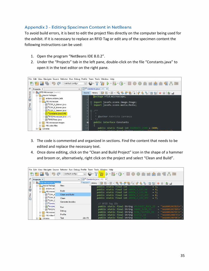
To avoid build errors, it is best to edit the project files directly on the computer being used for
the exhibit. If it is necessary to replace an RFID Tag or edit any of the specimen content the
following instructions can be used:
1. Open the program “NetBeans IDE 8.0.2”.
2. Under the “Projects” tab in the left pane, double-click on the file “Constants.java” to
open it in the text editor on the right pane.
3. The code is commented and organized in sections. Find the content that needs to be
edited and replace the necessary text.
4. Once done editing, click on the “Clean and Build Project” icon in the shape of a hammer
and broom or, alternatively, right click on the project and select “Clean and Build”.
36
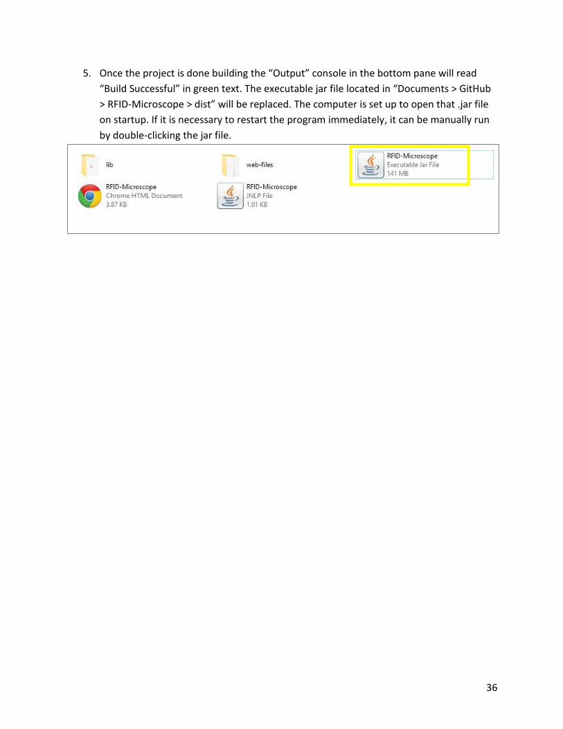
5. Once the project is done building the “Output” console in the bottom pane will read
“Build Successful” in green text. The executable jar file located in “Documents > GitHub
> RFID-Microscope > dist” will be replaced. The computer is set up to open that .jar file
on startup. If it is necessary to restart the program immediately, it can be manually run
by double-clicking the jar file.
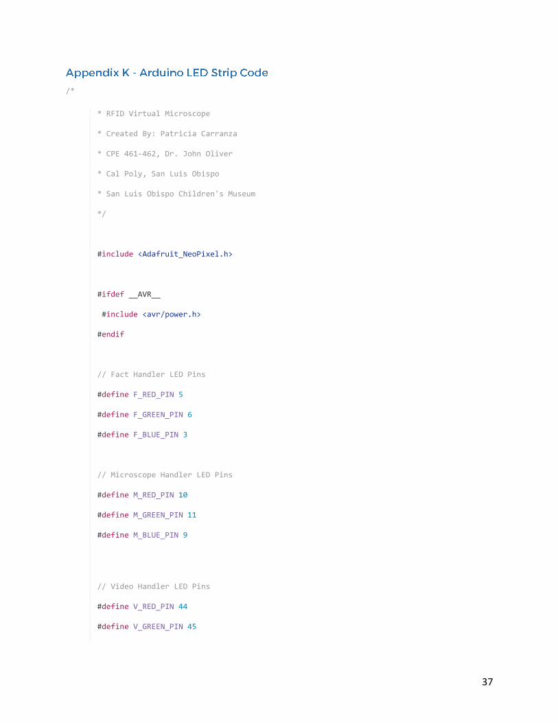
37
/*
* RFID Virtual Microscope
* Created By: Patricia Carranza
* CPE 461-462, Dr. John Oliver
* Cal Poly, San Luis Obispo
* San Luis Obispo Children's Museum
*/
#include <Adafruit_NeoPixel.h>
#ifdef __AVR__
#include <avr/power.h>
#endif
// Fact Handler LED Pins
#define F_RED_PIN 5
#define F_GREEN_PIN 6
#define F_BLUE_PIN 3
// Microscope Handler LED Pins
#define M_RED_PIN 10
#define M_GREEN_PIN 11
#define M_BLUE_PIN 9
// Video Handler LED Pins
#define V_RED_PIN 44
#define V_GREEN_PIN 45
38
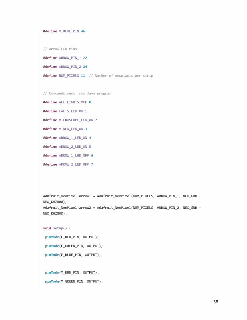
#define V_BLUE_PIN 46
// Arrow LED Pins
#define ARROW_PIN_1 22
#define ARROW_PIN_2 24
#define NUM_PIXELS 11 // Number of neopixels per strip
// Commands sent from Java program
#define ALL_LIGHTS_OFF 0
#define FACTS_LED_ON 1
#define MICROSCOPE_LED_ON 2
#define VIDEO_LED_ON 3
#define ARROW_1_LED_ON 4
#define ARROW_2_LED_ON 5
#define ARROW_1_LED_OFF 6
#define ARROW_2_LED_OFF 7
Adafruit_NeoPixel arrow1 = Adafruit_NeoPixel(NUM_PIXELS, ARROW_PIN_1, NEO_GRB +
NEO_KHZ800);
Adafruit_NeoPixel arrow2 = Adafruit_NeoPixel(NUM_PIXELS, ARROW_PIN_2, NEO_GRB +
NEO_KHZ800);
void setup() {
pinMode(F_RED_PIN, OUTPUT);
pinMode(F_GREEN_PIN, OUTPUT);
pinMode(F_BLUE_PIN, OUTPUT);
pinMode(M_RED_PIN, OUTPUT);
pinMode(M_GREEN_PIN, OUTPUT);
39
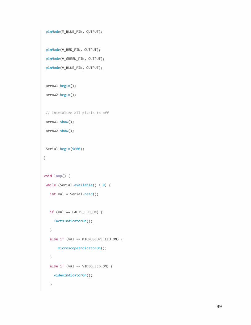
pinMode(M_BLUE_PIN, OUTPUT);
pinMode(V_RED_PIN, OUTPUT);
pinMode(V_GREEN_PIN, OUTPUT);
pinMode(V_BLUE_PIN, OUTPUT);
arrow1.begin();
arrow2.begin();
// Initialize all pixels to off
arrow1.show();
arrow2.show();
Serial.begin(9600);
}
void loop() {
while (Serial.available() > 0) {
int val = Serial.read();
if (val == FACTS_LED_ON) {
factsIndicatorOn();
}
else if (val == MICROSCOPE_LED_ON) {
microscopeIndicatorOn();
}
else if (val == VIDEO_LED_ON) {
videoIndicatorOn();
}
40
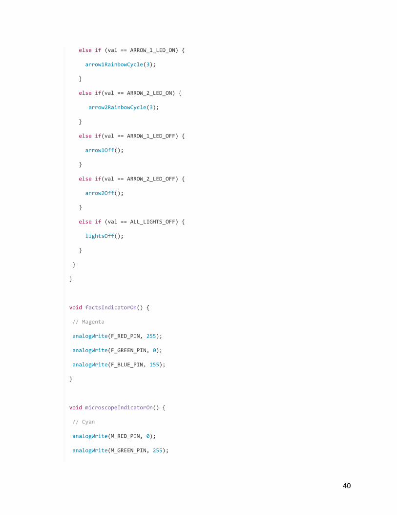
else if (val == ARROW_1_LED_ON) {
arrow1RainbowCycle(3);
}
else if(val == ARROW_2_LED_ON) {
arrow2RainbowCycle(3);
}
else if(val == ARROW_1_LED_OFF) {
arrow1Off();
}
else if(val == ARROW_2_LED_OFF) {
arrow2Off();
}
else if (val == ALL_LIGHTS_OFF) {
lightsOff();
}
}
}
void factsIndicatorOn() {
// Magenta
analogWrite(F_RED_PIN, 255);
analogWrite(F_GREEN_PIN, 0);
analogWrite(F_BLUE_PIN, 155);
}
void microscopeIndicatorOn() {
// Cyan
analogWrite(M_RED_PIN, 0);
analogWrite(M_GREEN_PIN, 255);
41
analogWrite(M_BLUE_PIN, 255);
}
void videoIndicatorOn() {
// Yellow
analogWrite(V_RED_PIN, 255);
analogWrite(V_GREEN_PIN, 200);
analogWrite(V_BLUE_PIN, 0);
}
void lightsOff() {
analogWrite(F_RED_PIN, 0);
analogWrite(F_GREEN_PIN, 0);
analogWrite(F_BLUE_PIN, 0);
analogWrite(M_RED_PIN, 0);
analogWrite(M_GREEN_PIN, 0);
analogWrite(M_BLUE_PIN, 0);
analogWrite(V_RED_PIN, 0);
analogWrite(V_GREEN_PIN, 0);
analogWrite(V_BLUE_PIN, 0);
arrow1Off();
arrow2Off();
}
/* Arrow 1 Rainbow Functions */
42
void arrow1RainbowCycle(uint8_t wait) {
uint16_t i, j;
for(j = 0; j < 256; j++) {
for(i = 0; i< arrow1.numPixels(); i++) {
arrow1.setPixelColor(i, arrow1Wheel(((i * 256 / arrow1.numPixels()) + j) &
255));
}
arrow1.show();
delay(wait);
}
}
// Input a value 0 to 255 to get a color value.
// The colours are a transition r - g - b - back to r.
uint32_t arrow1Wheel(byte WheelPos) {
WheelPos = 255 - WheelPos;
if(WheelPos < 85) {
return arrow1.Color(255 - WheelPos * 3, 0, WheelPos * 3);
}
if(WheelPos < 170) {
WheelPos -= 85;
return arrow1.Color(0, WheelPos * 3, 255 - WheelPos * 3);
}
WheelPos -= 170;
return arrow1.Color(WheelPos * 3, 255 - WheelPos * 3, 0);
}
void arrow1Off() {
int i;
43
for (i = 0; i < arrow1.numPixels(); i++) {
arrow1.setPixelColor(i, arrow1.Color(0, 0, 0));
}
arrow1.show();
}
/* Arrow 2 Rainbow Functions */
void arrow2RainbowCycle(uint8_t wait) {
uint16_t i, j;
for(j = 0; j < 256; j++) {
for(i = 0; i< arrow2.numPixels(); i++) {
arrow2.setPixelColor(i, arrow2Wheel(((i * 256 / arrow2.numPixels()) + j) &
255));
}
arrow2.show();
delay(wait);
}
}
// Input a value 0 to 255 to get a color value.
// The colours are a transition r - g - b - back to r.
uint32_t arrow2Wheel(byte WheelPos) {
WheelPos = 255 - WheelPos;
if(WheelPos < 85) {
return arrow2.Color(255 - WheelPos * 3, 0, WheelPos * 3);
}
if(WheelPos < 170) {
44
WheelPos -= 85;
return arrow2.Color(0, WheelPos * 3, 255 - WheelPos * 3);
}
WheelPos -= 170;
return arrow2.Color(WheelPos * 3, 255 - WheelPos * 3, 0);
}
void arrow2Off() {
int i;
for (i = 0; i < arrow2.numPixels(); i++) {
arrow2.setPixelColor(i, arrow2.Color(0, 0, 0));
}
arrow2.show();
}