Embed Size (px)
Citation preview
BY PASS DUST TRANSPORT AND CONSUMPTION SYSTEM SCOPE OF WORKS
D E C E M B E R 2 0 1 1
Page 1
The scope of work for the Project has been described herewith in three categories:
1. Civil.
2. Mechanical.
3. Electrical & Instrumentation.
General Contract terms & Conditions:
The Fabrication and Erection contractor must have the capabilities to execute all the above categories of works & should have skilled human
resources in all above categories to supervise the project activities, and for these purposes, the Fabrication and Erection Contractor
acknowledges and confirms that he acquired fully the capabilities and the skilled human resources to execute the Scope of work to the full
satisfaction of the Owner.
The Fabrication and Erection Contractor has to start from the existing completed and erected stage of the project & should complete the project
according to the full satisfaction of the QCC.
The Fabrication and erection contractor admitted that he visit the QCC project site and clearly understand the scope of works before submitting
the quotation.
The Fabrication and Erection contractor has to arrange required carnage, tools, tackles, scaffolding material, consumables, fittings, etc…. on his
scope that are required to complete successfully the project.
The cranes to be used for the Project should have certification from authentic agencies & such certifying agency should have to be accepted by
QCC safety section.
The Fabrication and Erection Contractor has to comply with safety rules, regulations & procedures that are enforced by the QCC safety
department. The Fabrication and Erection Contractor should observe and follow the Safety instructions given to him from time to time by QCC’s
safety inspectors. The QCC’s safety section has full rights to stop any of the ongoing activity which could be termed as dangerous according to
the safety point of view. The Erection Contractor needs to immediately rectify the defects & fulfill the safety requirement. The Fabrication and
Erection contractor is fully responsible for the delays that emerge due to any of such unsafe acts.
The Fabrication and Erection Contractor should provide all the required documents that are required to allow his employees to enter inside the
QCC plant premises in consultation with Procurement Department.
BY PASS DUST TRANSPORT AND CONSUMPTION SYSTEM SCOPE OF WORKS
D E C E M B E R 2 0 1 1
Page 2
To execute the Project if contractor need to isolate or block any of the roads that may reasonably hinder the movement of vehicles, he has to
inform & coordinate with QCC’s safety section prior a reasonable time of the commencement of work.
Both parties have to sign each page of the scope of works document as token of acceptance before awarding the Contract.
1. Civil :
Compressors : For this contractor to re use the existing foundations for the installation of New compressors. Prior Need to dismantle
the existing compressors along with drive motor, receiver tanks, air filter & all the dismantled items has to shift to the QCC store. Pour
50 mm concrete to make the level. Then According to the attached drawing make 6 holes by core drilling, fix the anchor bolts & to
perform the grouting. After completion of the job Contractor need to perform the back filling for the complete surrounding area.
For Air slides : Need to make opening in the wall of 300X300mm size at both PL1 & PL2 Cement mills to pass the air slide inside the mill
& thereafter perform the finishing.
The reference drawings are enclosed for the information.
2. Mechanical : The total Mechanical scope of works divided in to two sub categories :
A : Structural steel : Procurement, sand blasting , fabrication, painting, erection & installation.
B : Assembling, Erection , & Installation of QCC supplied bins, piping's, Equipments etc….
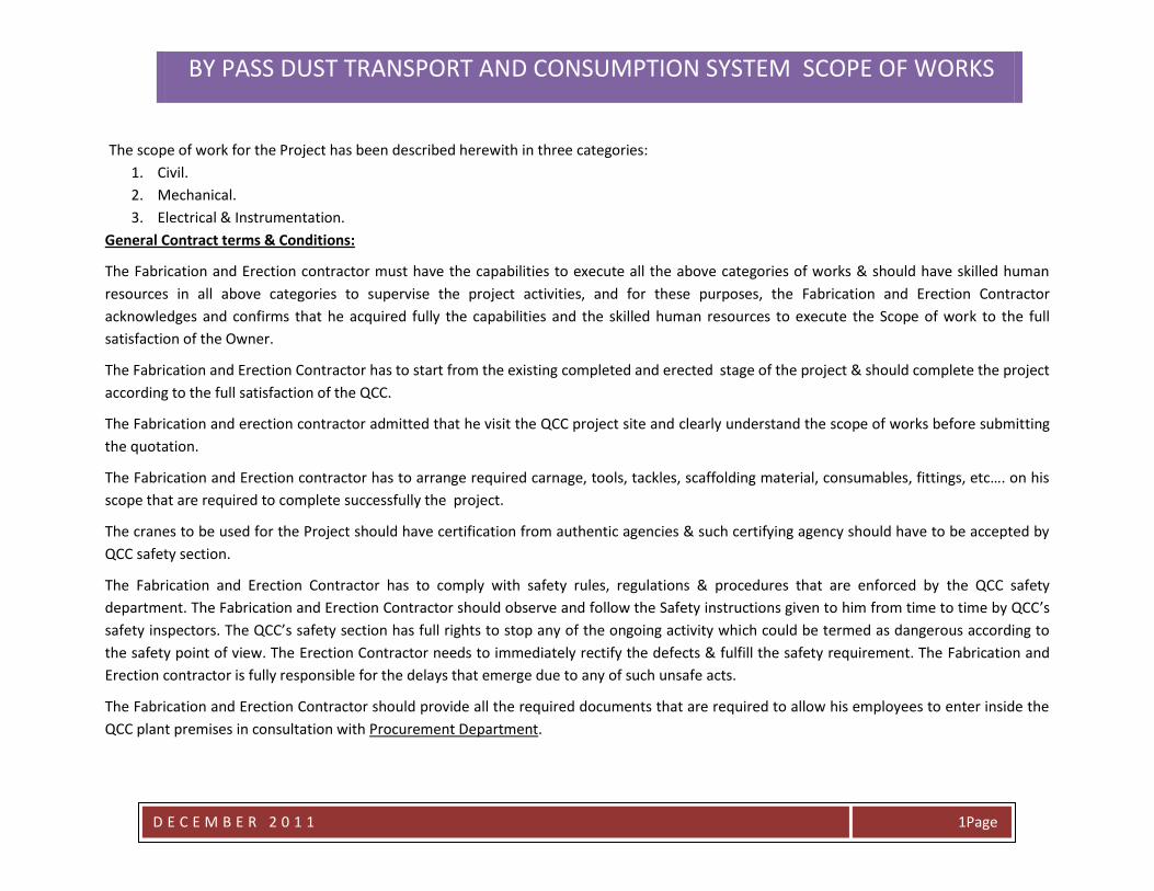
A : Structural steel & piping JOBS : as detailed below :
s.n Description Weight Kg Quantity Total
weight kg
Drawing no
01 Support structure for 100 ton bin 13,470 01 13,470 P-1-2007-163.
02 Support structure for 50 ton bin 12,522 02 25,044 P-1-2007-164.
03 Roof structures for 3 bins 985 03 2,955 P-1-2007-166.
04 Connecting walk way plat form
from PL3 Cement mill building to
100ton bin
397 01 397 P-1-2007-168.
05 Air slides maintenance plat form 1,150 3 3,450 P-1-2007-162.
06 Emergency truck loading platform 3,644 1 3,644 P-1-2007-165.
07 @+7.2m maintenance plat forms 1,024 3 3,072 P-1-2007-157/7.
BY PASS DUST TRANSPORT AND CONSUMPTION SYSTEM SCOPE OF WORKS
D E C E M B E R 2 0 1 1
Page 3
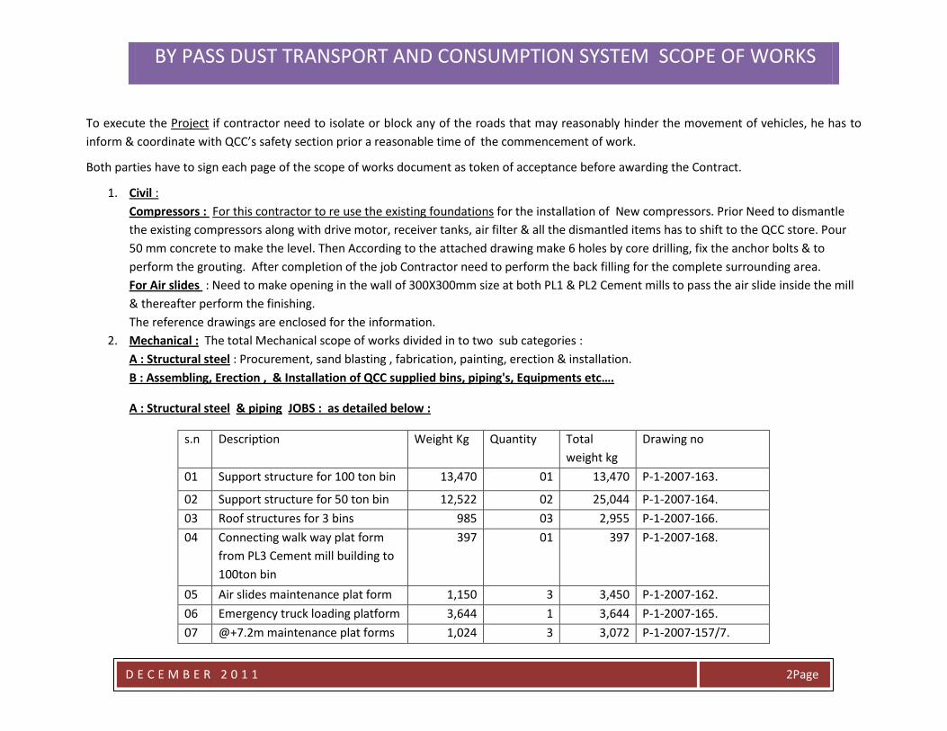
at 3 bins PL1,PL2 & PL3
08 @+5.2m maintenance plat form
at PL3 100ton bin
639 1 639 P-1-2007-157/6.
09 @+8.0m maintenance plat form
at PL3 100ton bin
1,275 1 1,275 P-1-2007-157/8.
10 PC pump hopper 186 2 372 3.5100.4.002
11 Miscellaneous steel required for
air slide fans, blowers, pc pumps,
compressors base frames &
chutes. (estimated)
5,000 1 5,000 These drawings will
be prepared during
the erection progress.
12 Feed chute to the pc pumps 1000 1 1,000 P-1-2007-148.
13 Maintenance plat forms for
diverters :
250 3 750 These will be installed
according to QCC
guidance.
14 Air slides 200TPH 350 1 350 These drawings will
be prepared soon. 15 Air slides 10TPH 700 1 700
16 Distribution box 3no 50 3 150
17
Miscellaneous steel required for
chutes & other steel work
according to site work (Reserve)
1500 1 1500 This quantity of steel
requirement is
assumed for
unforeseen jobs
Total 63,768 kg
BY PASS DUST TRANSPORT AND CONSUMPTION SYSTEM SCOPE OF WORKS
D E C E M B E R 2 0 1 1
Page 4
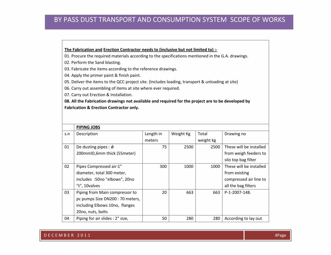
The Fabrication and Erection Contractor needs to (inclusive but not limited to) :-
01. Procure the required materials according to the specifications mentioned in the G.A. drawings.
02. Perform the Sand blasting.
03. Fabricate the items according to the reference drawings.
04. Apply the primer paint & finish paint.
05. Deliver the items to the QCC project site. (Includes loading, transport & unloading at site)
06. Carry out assembling of items at site where ever required.
07. Carry out Erection & Installation.
08. All the Fabrication drawings not available and required for the project are to be developed by
Fabrication & Erection Contractor only.
PIPING JOBS
s.n Description Length in
meters
Weight Kg Total
weight kg
Drawing no
01 De dusting pipes : ǿ
200mmID,6mm thick (55meter)
75 2500 2500 These will be installed
from weigh feeders to
silo top bag filter
02 Pipes Compressed air:1"
diameter, total 300 meter,
includes :50no "elbows", 20no
"t", 10valves
300 1000 1000 These will be installed
from existing
compressed air line to
all the bag filters
03 Piping from Main compressor to
pc pumps Size DN200 : 70 meters,
including Elbows 10no, flanges
20no, nuts, bolts
20 663 663 P-1-2007-148.
04 Piping for air slides : 2" size, 50 280 280 According to lay out
BY PASS DUST TRANSPORT AND CONSUMPTION SYSTEM SCOPE OF WORKS
D E C E M B E R 2 0 1 1
Page 5
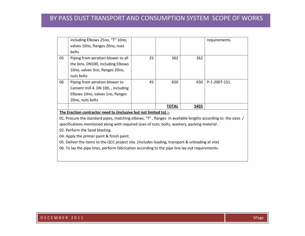
including Elbows 25no, "T" 10no,
valves 10no, flanges 20no, nuts
bolts
requirements.
05 Piping from aeration blower to all
the bins. DN100, including Elbows
10no, valves 3no, flanges 20no,
nuts bolts
25 362 362
06 Piping from aeration blower to
Cement mill 4. DN 100, , including
Elbows 10no, valves 1no, flanges
20no, nuts bolts
45 650 650 P-1-2007-151.
TOTAL 5455
The Erection contractor need to (inclusive but not limited to) :-
01. Procure the standard pipes, matching elbows, "T" , flanges in available lengths according to the sizes /
specifications mentioned along with required sizes of nuts, bolts, washers, packing material .
02. Perform the Sand blasting.
04. Apply the primer paint & finish paint.
05. Deliver the items to the QCC project site. (Includes loading, transport & unloading at site)
06. To lay the pipe lines, perform fabrication according to the pipe line lay out requirements.
BY PASS DUST TRANSPORT AND CONSUMPTION SYSTEM SCOPE OF WORKS
D E C E M B E R 2 0 1 1
Page 6
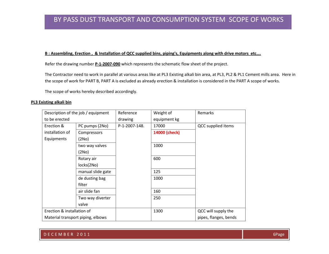
B : Assembling, Erection , & Installation of QCC supplied bins, piping's, Equipments along with drive motors etc….
Refer the drawing number P-1-2007-090 which represents the schematic flow sheet of the project.
The Contractor need to work in parallel at various areas like at PL3 Existing alkali bin area, at PL3, PL2 & PL1 Cement mills area. Here in
the scope of work for PART B, PART A is excluded as already erection & installation is considered in the PART A scope of works.
The scope of works hereby described accordingly.
PL3 Existing alkali bin
Description of the job / equipment
to be erected
Reference
drawing
Weight of
equipment kg
Remarks
Erection &
installation of
Equipments
PC pumps (2No) P-1-2007-148.
17000 QCC supplied items
Compressors
(2No)
14000 (check)
two way valves
(2No)
1000
Rotary air
locks(2No)
600
manual slide gate 125
de dusting bag
filter
1000
air slide fan 160
Two way diverter
valve
250
Erection & installation of
Material transport piping, elbows
1300
QCC will supply the
pipes, flanges, bends
BY PASS DUST TRANSPORT AND CONSUMPTION SYSTEM SCOPE OF WORKS
D E C E M B E R 2 0 1 1
Page 7
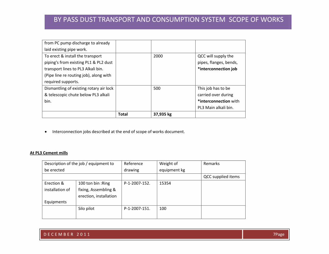
from PC pump discharge to already
laid existing pipe work.
To erect & install the transport
piping's from existing PL1 & PL2 dust
transport lines to PL3 Alkali bin.
(Pipe line re routing job), along with
required supports.
2000 QCC will supply the
pipes, flanges, bends,
*interconnection job
Dismantling of existing rotary air lock
& telescopic chute below PL3 alkali
bin.
500 This job has to be
carried over during
*interconnection with
PL3 Main alkali bin.
Total 37,935 kg
Interconnection jobs described at the end of scope of works document.
At PL3 Cement mills
Description of the job / equipment to
be erected
Reference
drawing
Weight of
equipment kg
Remarks
QCC supplied items
Erection &
installation of
Equipments
100 ton bin :Ring
fixing, Assembling &
erection, installation
P-1-2007-152.
15354
Silo pilot P-1-2007-151. 100
BY PASS DUST TRANSPORT AND CONSUMPTION SYSTEM SCOPE OF WORKS
D E C E M B E R 2 0 1 1
Page 8
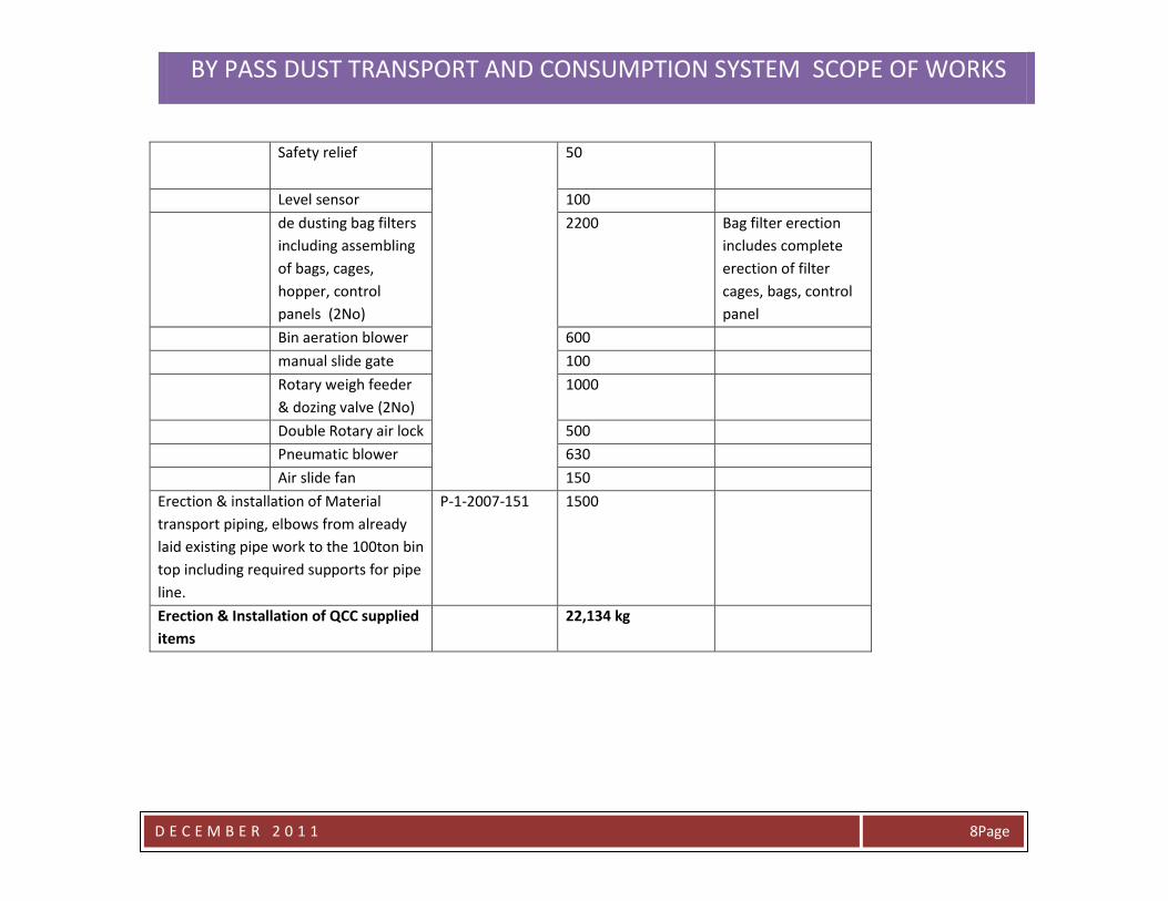
Safety relief 50
Level sensor 100
de dusting bag filters
including assembling
of bags, cages,
hopper, control
panels (2No)
2200 Bag filter erection
includes complete
erection of filter
cages, bags, control
panel
Bin aeration blower 600
manual slide gate 100
Rotary weigh feeder
& dozing valve (2No)
1000
Double Rotary air lock 500
Pneumatic blower 630
Air slide fan 150
Erection & installation of Material
transport piping, elbows from already
laid existing pipe work to the 100ton bin
top including required supports for pipe
line.
P-1-2007-151 1500
Erection & Installation of QCC supplied
items
22,134 kg
BY PASS DUST TRANSPORT AND CONSUMPTION SYSTEM SCOPE OF WORKS
D E C E M B E R 2 0 1 1
Page 9
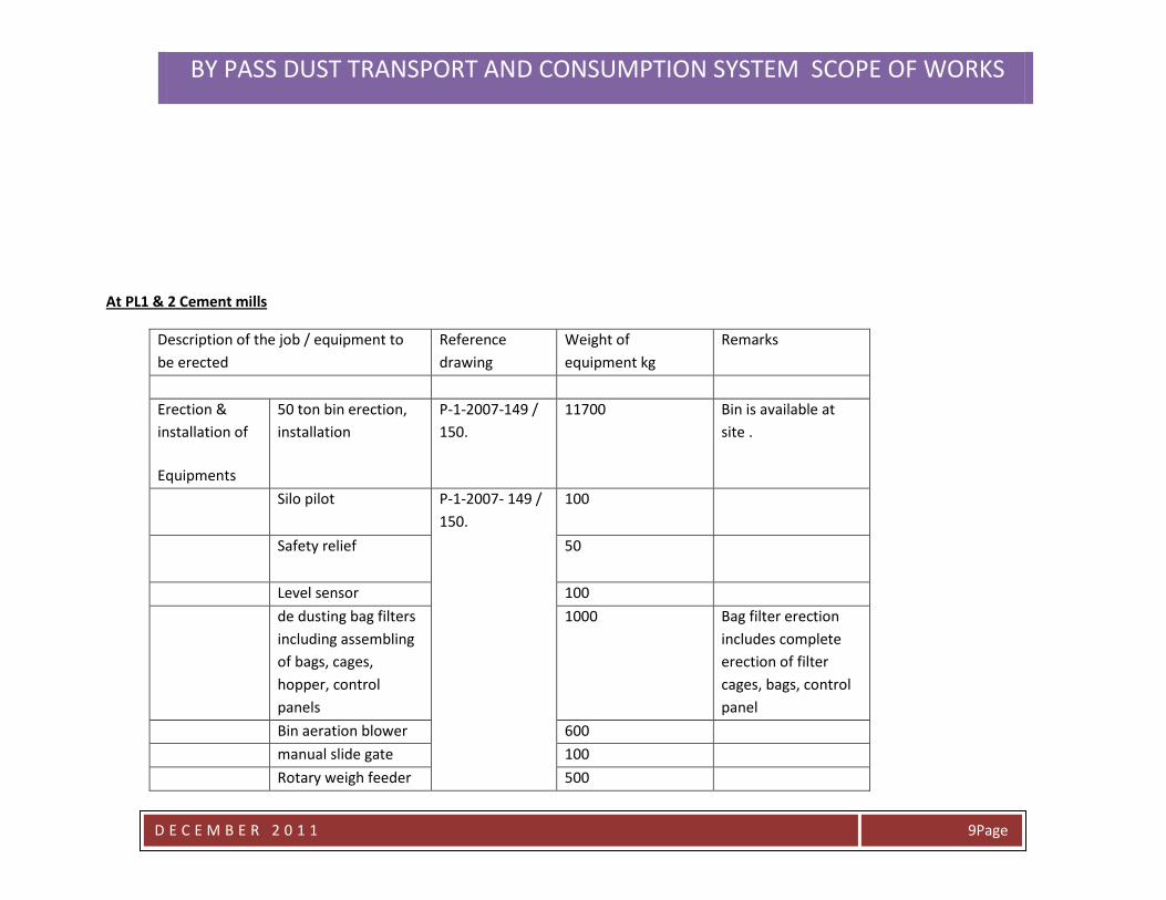
At PL1 & 2 Cement mills
Description of the job / equipment to
be erected
Reference
drawing
Weight of
equipment kg
Remarks
Erection &
installation of
Equipments
50 ton bin erection,
installation
P-1-2007-149 /
150.
11700 Bin is available at
site .
Silo pilot P-1-2007- 149 /
150.
100
Safety relief 50
Level sensor 100
de dusting bag filters
including assembling
of bags, cages,
hopper, control
panels
1000 Bag filter erection
includes complete
erection of filter
cages, bags, control
panel
Bin aeration blower 600
manual slide gate 100
Rotary weigh feeder 500
BY PASS DUST TRANSPORT AND CONSUMPTION SYSTEM SCOPE OF WORKS
D E C E M B E R 2 0 1 1
Page 11
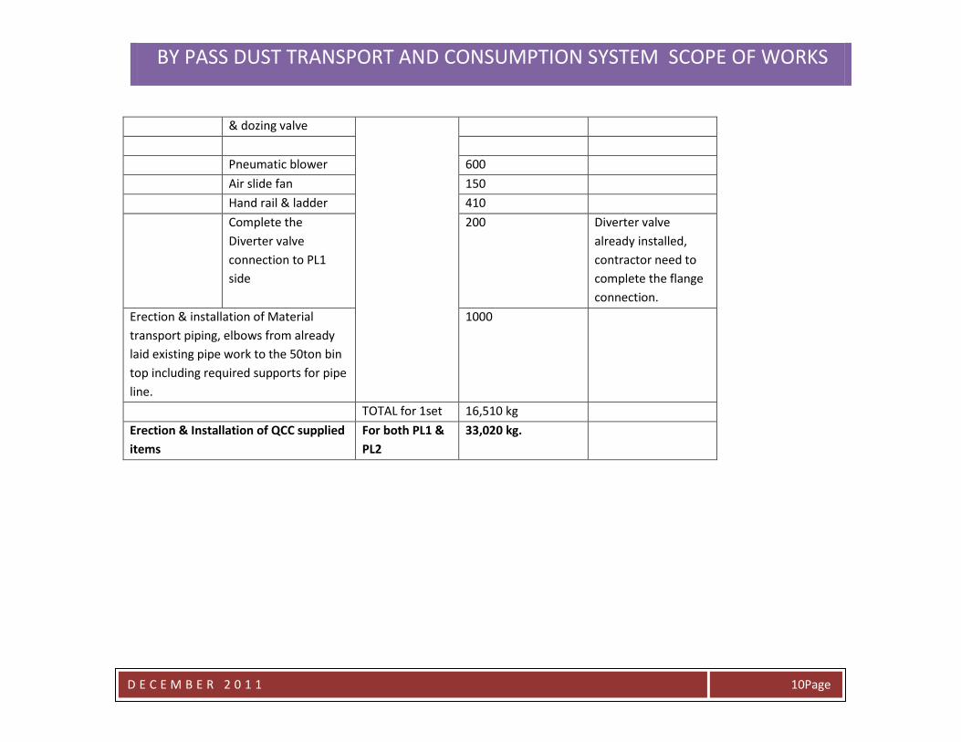
& dozing valve
Pneumatic blower 600
Air slide fan 150
Hand rail & ladder 410
Complete the
Diverter valve
connection to PL1
side
200 Diverter valve
already installed,
contractor need to
complete the flange
connection.
Erection & installation of Material
transport piping, elbows from already
laid existing pipe work to the 50ton bin
top including required supports for pipe
line.
1000
TOTAL for 1set 16,510 kg
Erection & Installation of QCC supplied
items
For both PL1 &
PL2
33,020 kg.
BY PASS DUST TRANSPORT AND CONSUMPTION SYSTEM SCOPE OF WORKS
D E C E M B E R 2 0 1 1
Page 11
C : Electrical & Instrumentation jobs
The Contractor has to comply with the Panels & Cables as per the QCC recommended Specifications. In case of any alteration in recommended
specifications should be approved from QCC Electrical department well before commencement of work.
The Contractor should provide all the Planned LV, HV, Panel & Network wiring diagram well before commencement of work for approvals from
QCC electrical Department & four numbers of Hard copy, one numbers of softcopy As built after compilation of project.
To execute the project if contractor need to isolate power, equipment which can interrupt the process, need to inform & coordinate with QCC
Electrical Department well before the commencement of work.
The Fabrication and Erection Contractor has to comply with regulations & procedures that are enforced by the QCC electrical department. The
Contractor should also follow the instructions given to him from time to time by QCC electrical department. The QCC electrical department also
has the rights to stop any of the ongoing activity which could be termed as dangerous for the process according to the Electrical point of view.
The contractor needs to immediately rectify the defects & fulfill the requirement.
The Erection contractor has to sign each page of the scope of works document as token of acceptance before awarding the contract.
A : Electrical jobs
The Scope of Works comprises of:
01. Procurement & Installation of cable trays with required supports.
02. Procurement & Installation of cable conduit pipes with required clamping fixing arrangements.
03. Procurement, pulling of power cables from QCC MCC rooms up to the drive motors.
04. To perform required terminations for the power cables towards MCC & drive motor sides.
06. Procurement & installation of tube light fittings at new equipments locations.
07. Procurement & installation of Power sockets at new equipments locations
BY PASS DUST TRANSPORT AND CONSUMPTION SYSTEM SCOPE OF WORKS
D E C E M B E R 2 0 1 1
Page 12
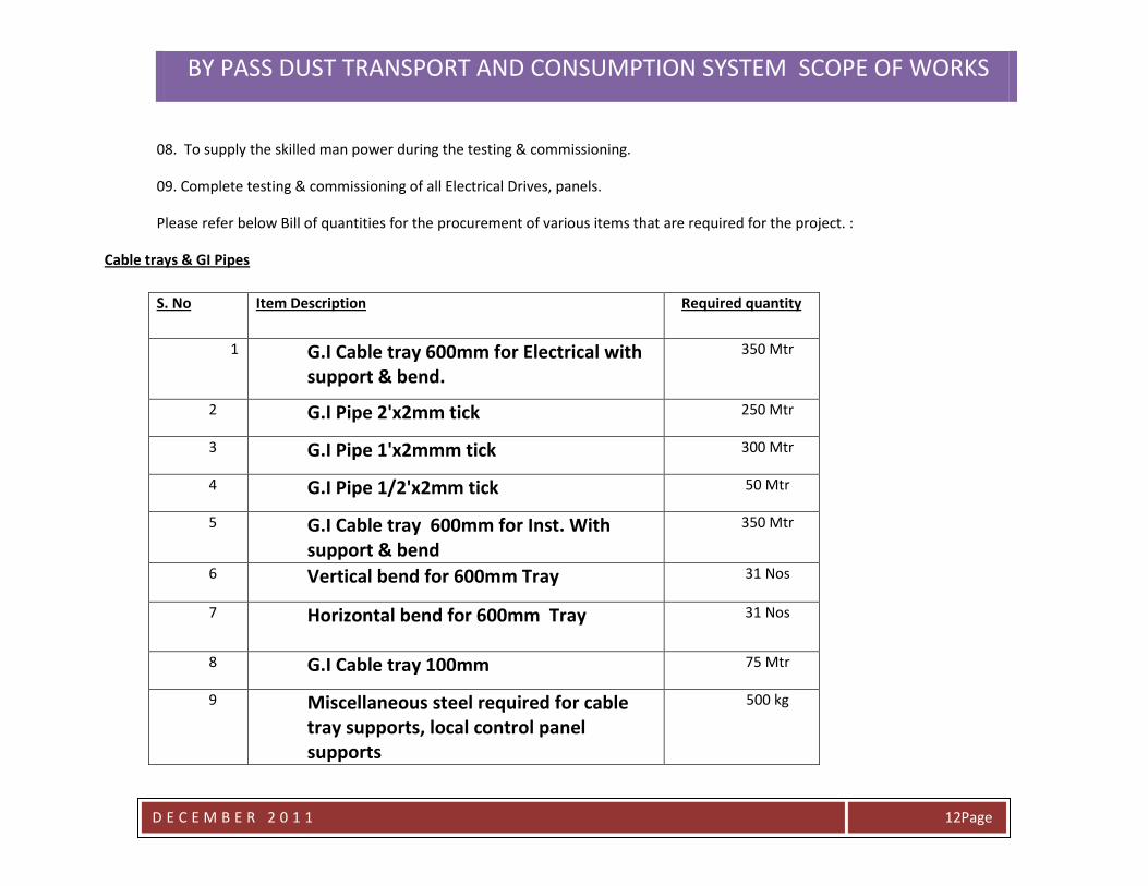
08. To supply the skilled man power during the testing & commissioning.
09. Complete testing & commissioning of all Electrical Drives, panels.
Please refer below Bill of quantities for the procurement of various items that are required for the project. :
Cable trays & GI Pipes
S. No Item Description Required quantity
1 G.I Cable tray 600mm for Electrical with support & bend.
350 Mtr
2 G.I Pipe 2'x2mm tick 250 Mtr
3 G.I Pipe 1'x2mmm tick 300 Mtr
4 G.I Pipe 1/2'x2mm tick 50 Mtr
5 G.I Cable tray 600mm for Inst. With support & bend
350 Mtr
6 Vertical bend for 600mm Tray 31 Nos
7 Horizontal bend for 600mm Tray 31 Nos
8 G.I Cable tray 100mm 75 Mtr
9 Miscellaneous steel required for cable tray supports, local control panel supports
500 kg
BY PASS DUST TRANSPORT AND CONSUMPTION SYSTEM SCOPE OF WORKS
D E C E M B E R 2 0 1 1
Page 13
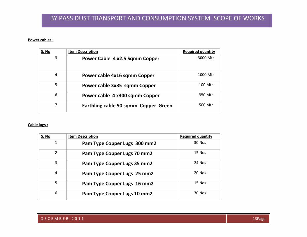
Power cables :
S. No Item Description Required quantity
3 Power Cable 4 x2.5 Sqmm Copper 3000 Mtr
4 Power cable 4x16 sqmm Copper 1000 Mtr
5 Power cable 3x35 sqmm Copper 100 Mtr
6 Power cable 4 x300 sqmm Copper 350 Mtr
7 Earthling cable 50 sqmm Copper Green 500 Mtr
Cable lugs :
S. No Item Description Required quantity
1 Pam Type Copper Lugs 300 mm2 30 Nos
2 Pam Type Copper Lugs 70 mm2 15 Nos
3 Pam Type Copper Lugs 35 mm2 24 Nos
4 Pam Type Copper Lugs 25 mm2 20 Nos
5 Pam Type Copper Lugs 16 mm2 15 Nos
6 Pam Type Copper Lugs 10 mm2 30 Nos
BY PASS DUST TRANSPORT AND CONSUMPTION SYSTEM SCOPE OF WORKS
D E C E M B E R 2 0 1 1
Page 14
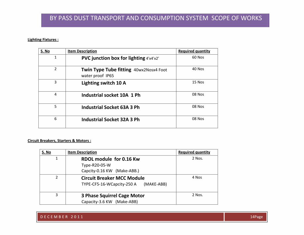
Lighting Fixtures :
S. No Item Description Required quantity
1 PVC junction box for lighting 4'x4'x2' 60 Nos
2 Twin Type Tube fitting 40wx2Nosx4 Foot
water proof IP65
40 Nos
3 Lighting switch 10 A 15 Nos
4 Industrial socket 10A 1 Ph 08 Nos
5 Industrial Socket 63A 3 Ph 08 Nos
6 Industrial Socket 32A 3 Ph 08 Nos
Circuit Breakers, Starters & Motors :
S. No Item Description Required quantity
1 RDOL module for 0.16 Kw Type-R20-05-W Capcity-0.16 KW (Make-ABB.)
2 Nos.
2 Circuit Breaker MCC Module TYPE-CF5-16-WCapcity-250 A (MAKE-ABB)
4 Nos
3 3 Phase Squirrel Cage Motor Capacity-3.6 KW (Make-ABB)
2 Nos.
BY PASS DUST TRANSPORT AND CONSUMPTION SYSTEM SCOPE OF WORKS
D E C E M B E R 2 0 1 1
Page 15
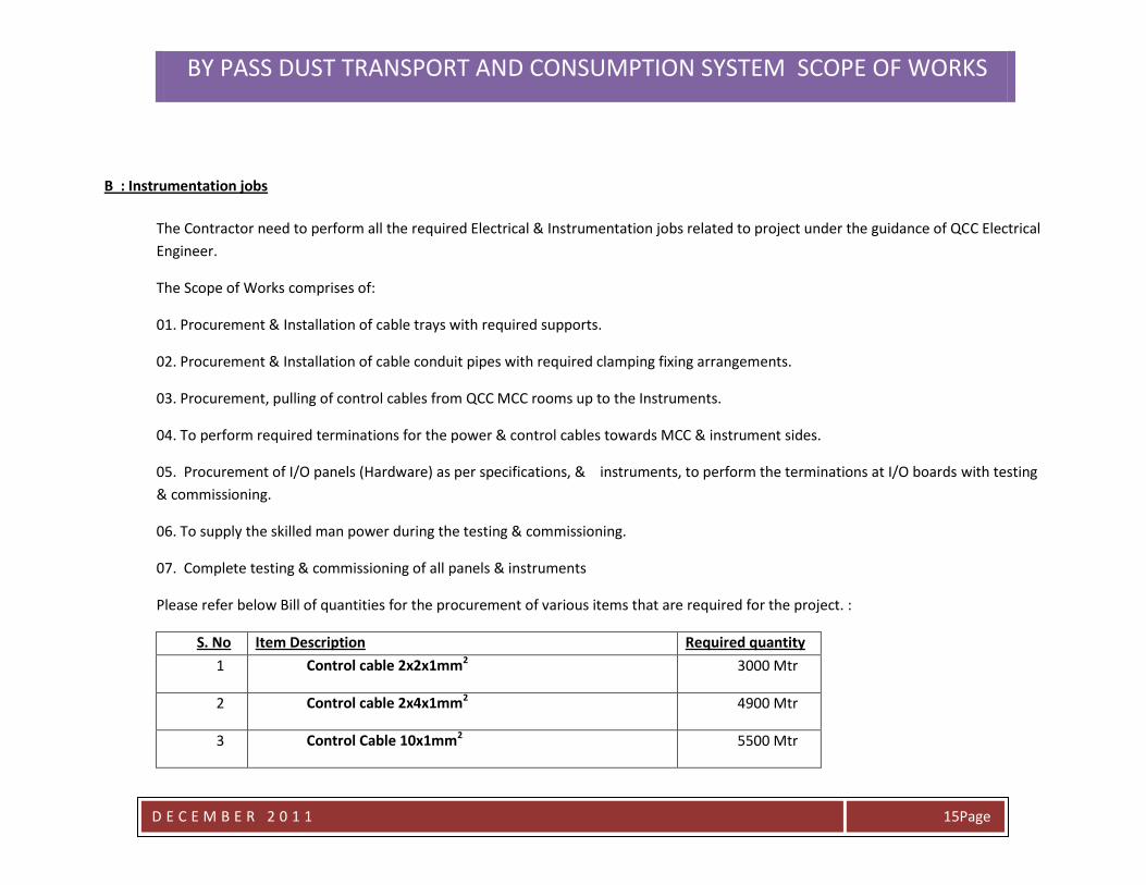
B : Instrumentation jobs
The Contractor need to perform all the required Electrical & Instrumentation jobs related to project under the guidance of QCC Electrical
Engineer.
The Scope of Works comprises of:
01. Procurement & Installation of cable trays with required supports.
02. Procurement & Installation of cable conduit pipes with required clamping fixing arrangements.
03. Procurement, pulling of control cables from QCC MCC rooms up to the Instruments.
04. To perform required terminations for the power & control cables towards MCC & instrument sides.
05. Procurement of I/O panels (Hardware) as per specifications, & instruments, to perform the terminations at I/O boards with testing
& commissioning.
06. To supply the skilled man power during the testing & commissioning.
07. Complete testing & commissioning of all panels & instruments
Please refer below Bill of quantities for the procurement of various items that are required for the project. :
S. No Item Description Required quantity
1 Control cable 2x2x1mm2 3000 Mtr
2 Control cable 2x4x1mm2 4900 Mtr
3 Control Cable 10x1mm2 5500 Mtr
BY PASS DUST TRANSPORT AND CONSUMPTION SYSTEM SCOPE OF WORKS
D E C E M B E R 2 0 1 1
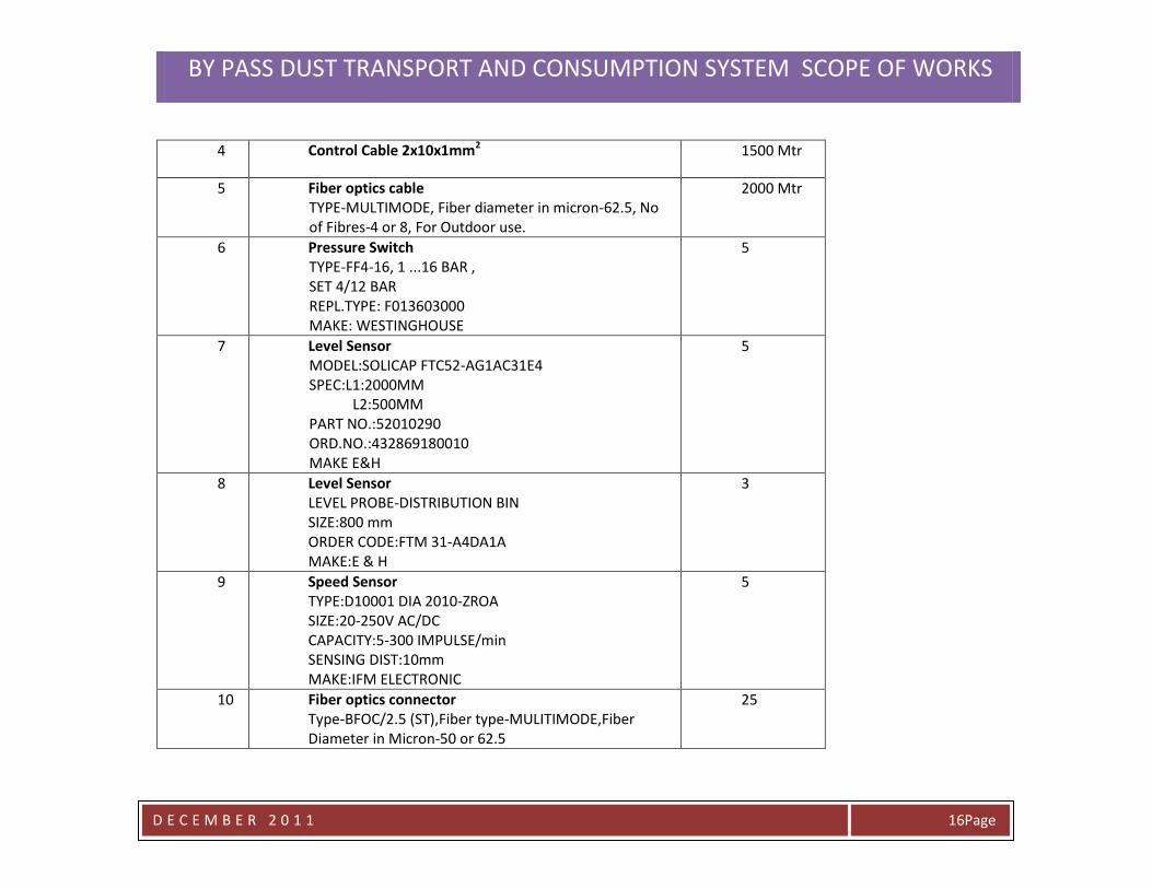
Page 16
4 Control Cable 2x10x1mm2 1500 Mtr
5 Fiber optics cable TYPE-MULTIMODE, Fiber diameter in micron-62.5, No of Fibres-4 or 8, For Outdoor use.
2000 Mtr
6 Pressure Switch TYPE-FF4-16, 1 ...16 BAR , SET 4/12 BAR REPL.TYPE: F013603000 MAKE: WESTINGHOUSE
5
7 Level Sensor MODEL:SOLICAP FTC52-AG1AC31E4 SPEC:L1:2000MM L2:500MM PART NO.:52010290 ORD.NO.:432869180010 MAKE E&H
5
8 Level Sensor LEVEL PROBE-DISTRIBUTION BIN SIZE:800 mm ORDER CODE:FTM 31-A4DA1A MAKE:E & H
3
9 Speed Sensor TYPE:D10001 DIA 2010-ZROA SIZE:20-250V AC/DC CAPACITY:5-300 IMPULSE/min SENSING DIST:10mm MAKE:IFM ELECTRONIC
5
10 Fiber optics connector Type-BFOC/2.5 (ST),Fiber type-MULITIMODE,Fiber Diameter in Micron-50 or 62.5
25
BY PASS DUST TRANSPORT AND CONSUMPTION SYSTEM SCOPE OF WORKS
D E C E M B E R 2 0 1 1
Page 17
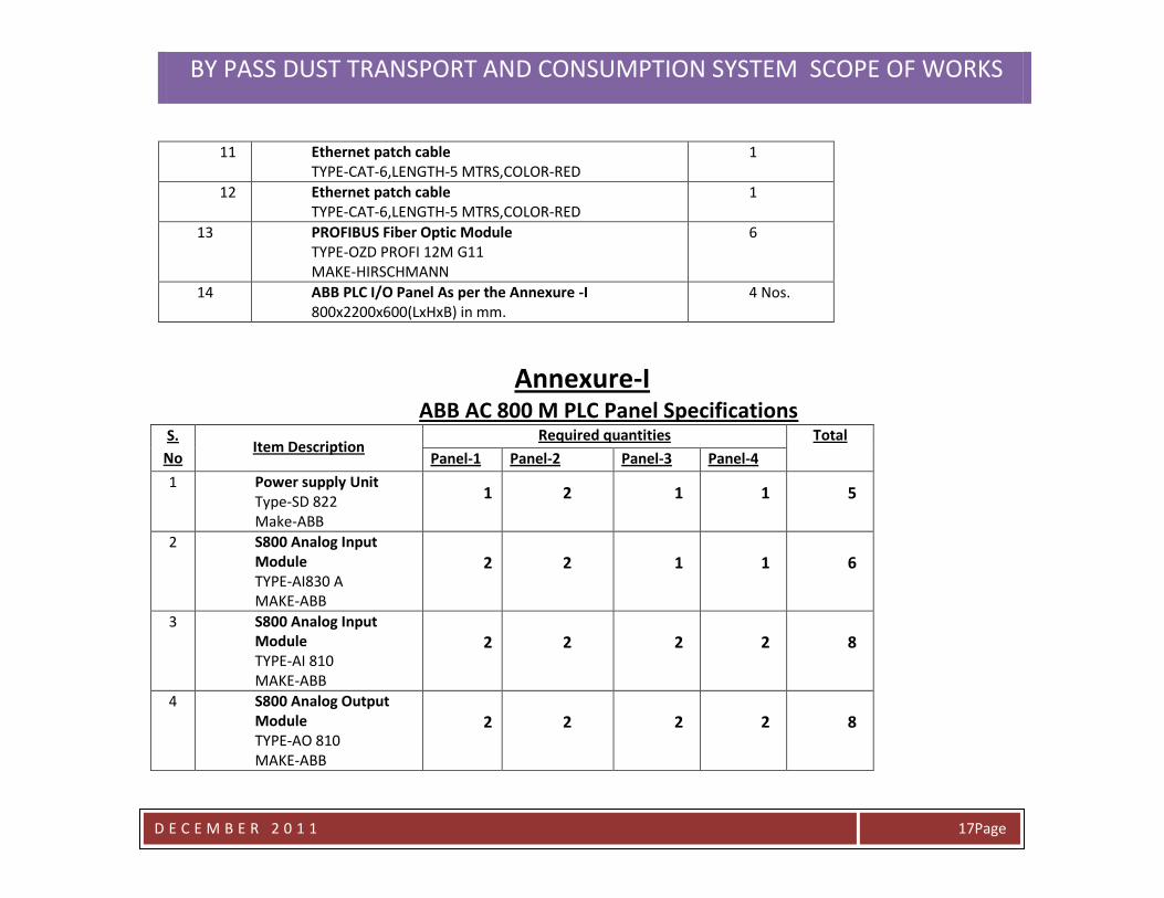
11 Ethernet patch cable TYPE-CAT-6,LENGTH-5 MTRS,COLOR-RED
1
12 Ethernet patch cable TYPE-CAT-6,LENGTH-5 MTRS,COLOR-RED
1
13 PROFIBUS Fiber Optic Module TYPE-OZD PROFI 12M G11 MAKE-HIRSCHMANN
6
14 ABB PLC I/O Panel As per the Annexure -I 800x2200x600(LxHxB) in mm.
4 Nos.
Annexure-I ABB AC 800 M PLC Panel Specifications
S.
No Item Description
Required quantities Total
Panel-1 Panel-2 Panel-3 Panel-4
1 Power supply Unit Type-SD 822 Make-ABB
1 2 1 1 5
2 S800 Analog Input Module TYPE-AI830 A MAKE-ABB
2 2 1 1 6
3 S800 Analog Input Module TYPE-AI 810 MAKE-ABB
2 2 2 2 8
4 S800 Analog Output Module TYPE-AO 810 MAKE-ABB
2 2 2 2 8
BY PASS DUST TRANSPORT AND CONSUMPTION SYSTEM SCOPE OF WORKS
D E C E M B E R 2 0 1 1
Page 18
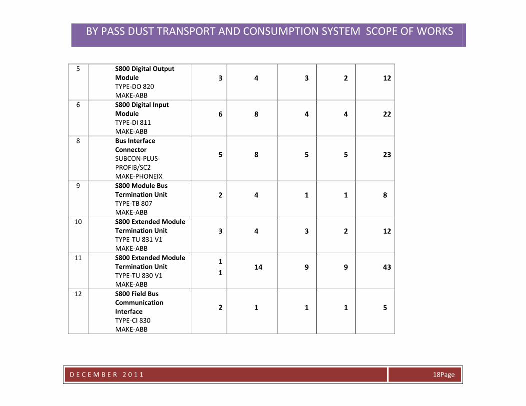
5 S800 Digital Output Module TYPE-DO 820 MAKE-ABB
3 4 3 2 12
6 S800 Digital Input Module TYPE-DI 811 MAKE-ABB
6 8 4 4 22
8 Bus Interface Connector SUBCON-PLUS-PROFIB/SC2 MAKE-PHONEIX
5 8 5 5 23
9 S800 Module Bus Termination Unit TYPE-TB 807 MAKE-ABB
2 4 1 1 8
10 S800 Extended Module Termination Unit TYPE-TU 831 V1 MAKE-ABB
3 4 3 2 12
11 S800 Extended Module Termination Unit TYPE-TU 830 V1 MAKE-ABB
1
1 14 9 9 43
12 S800 Field Bus Communication Interface TYPE-CI 830 MAKE-ABB
2 1 1 1 5
BY PASS DUST TRANSPORT AND CONSUMPTION SYSTEM SCOPE OF WORKS
D E C E M B E R 2 0 1 1
Page 19
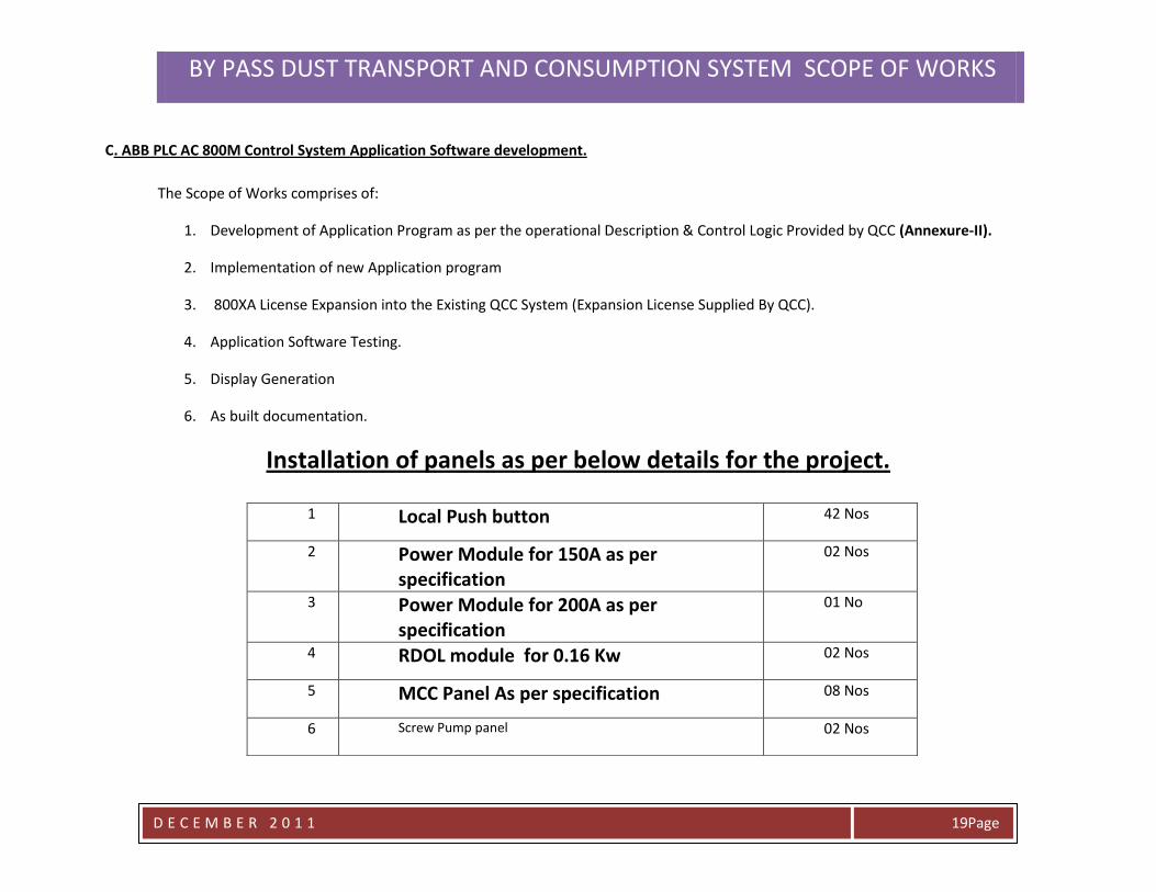
C. ABB PLC AC 800M Control System Application Software development.
The Scope of Works comprises of:
1. Development of Application Program as per the operational Description & Control Logic Provided by QCC (Annexure-II).
2. Implementation of new Application program
3. 800XA License Expansion into the Existing QCC System (Expansion License Supplied By QCC).
4. Application Software Testing.
5. Display Generation
6. As built documentation.
Installation of panels as per below details for the project.
42 Nos Local Push button 1
02 Nos Power Module for 150A as per specification
2
01 No Power Module for 200A as per specification
3
02 Nos RDOL module for 0.16 Kw 4
08 Nos MCC Panel As per specification 5
02 Nos Screw Pump panel 6
BY PASS DUST TRANSPORT AND CONSUMPTION SYSTEM SCOPE OF WORKS
D E C E M B E R 2 0 1 1
Page 21
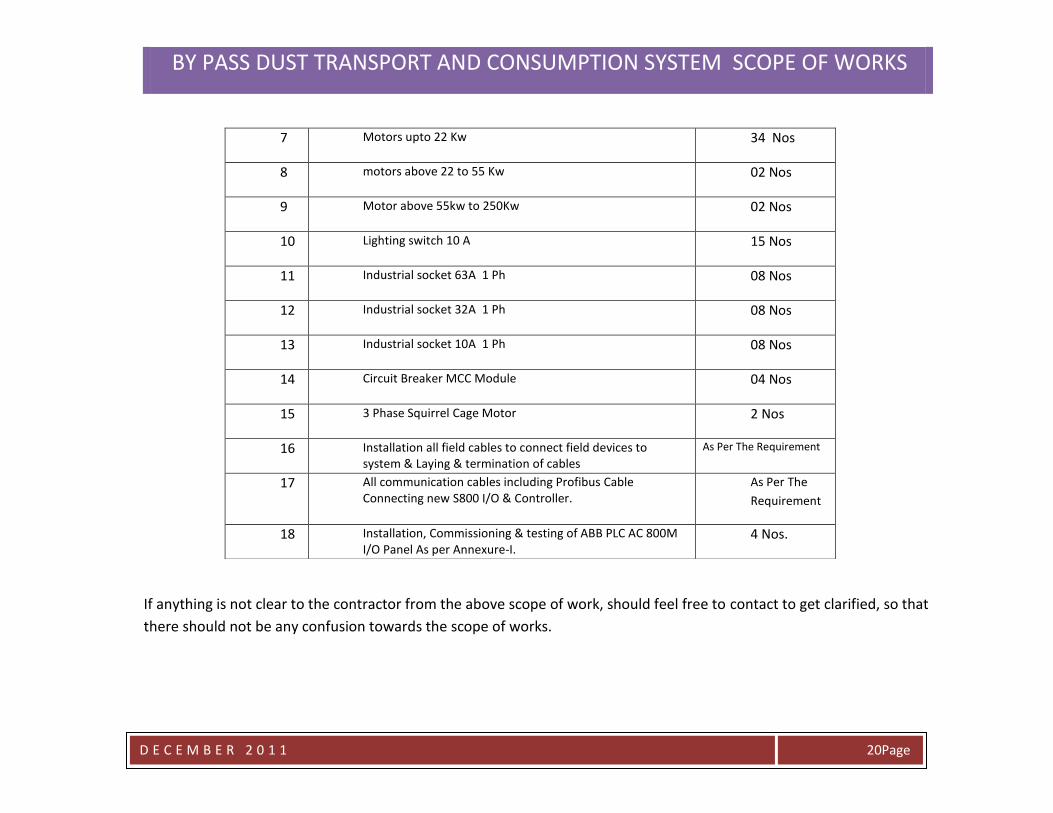
If anything is not clear to the contractor from the above scope of work, should feel free to contact to get clarified, so that
there should not be any confusion towards the scope of works.
34 Nos Motors upto 22 Kw 7
02 Nos motors above 22 to 55 Kw 8
02 Nos Motor above 55kw to 250Kw 9
15 Nos Lighting switch 10 A 10
08 Nos Industrial socket 63A 1 Ph 11
08 Nos Industrial socket 32A 1 Ph 12
08 Nos Industrial socket 10A 1 Ph 13
04 Nos Circuit Breaker MCC Module 14
2 Nos 3 Phase Squirrel Cage Motor 15
As Per The Requirement Installation all field cables to connect field devices to system & Laying & termination of cables
16
As Per The
Requirement
All communication cables including Profibus Cable Connecting new S800 I/O & Controller.
17
4 Nos. Installation, Commissioning & testing of ABB PLC AC 800M I/O Panel As per Annexure-I.
18
BY PASS DUST TRANSPORT AND CONSUMPTION SYSTEM SCOPE OF WORKS
D E C E M B E R 2 0 1 1
Page 21
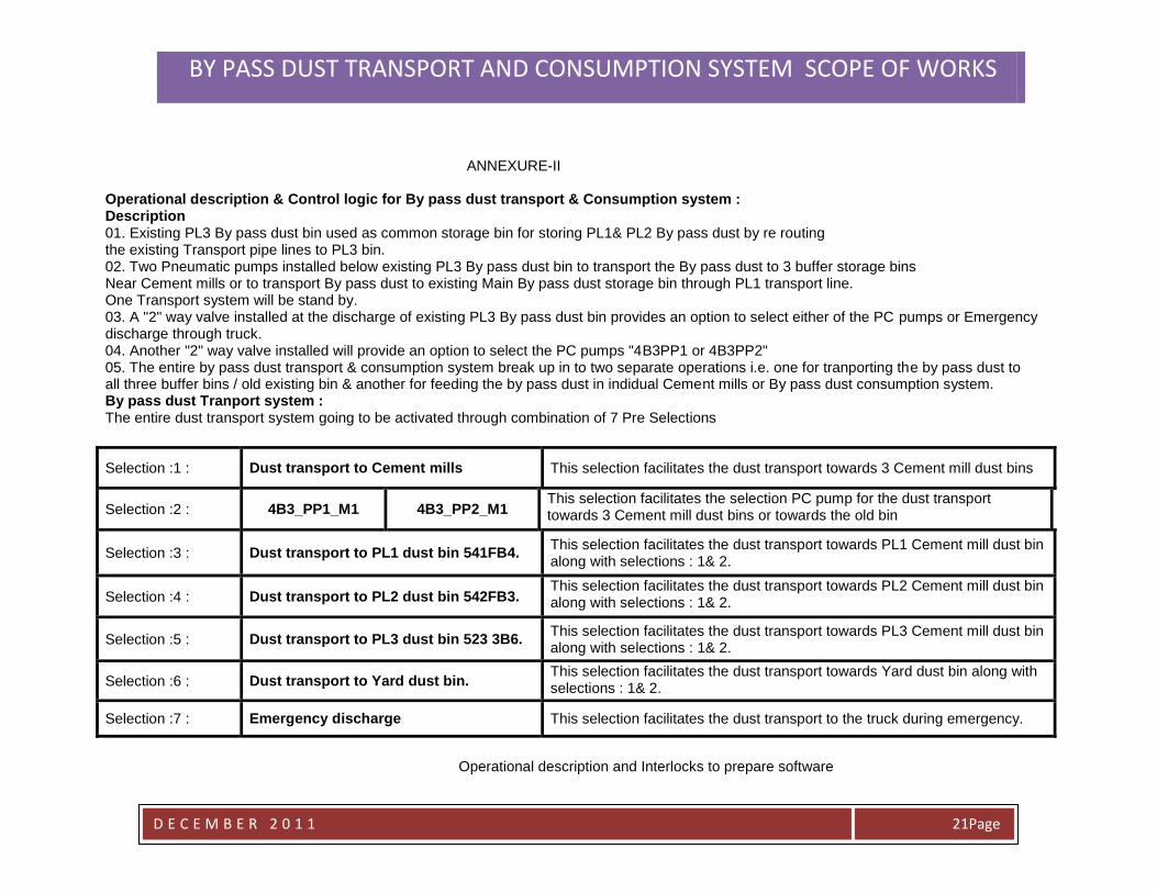
ANNEXURE-II Operational description & Control logic for By pass dust transport & Consumption system : Description 01. Existing PL3 By pass dust bin used as common storage bin for storing PL1& PL2 By pass dust by re routing the existing Transport pipe lines to PL3 bin. 02. Two Pneumatic pumps installed below existing PL3 By pass dust bin to transport the By pass dust to 3 buffer storage bins Near Cement mills or to transport By pass dust to existing Main By pass dust storage bin through PL1 transport line. One Transport system will be stand by. 03. A "2" way valve installed at the discharge of existing PL3 By pass dust bin provides an option to select either of the PC pumps or Emergency discharge through truck. 04. Another "2" way valve installed will provide an option to select the PC pumps "4B3PP1 or 4B3PP2" 05. The entire by pass dust transport & consumption system break up in to two separate operations i.e. one for tranporting the by pass dust to all three buffer bins / old existing bin & another for feeding the by pass dust in indidual Cement mills or By pass dust consumption system. By pass dust Tranport system : The entire dust transport system going to be activated through combination of 7 Pre Selections
Selection :1 : Dust transport to Cement mills This selection facilitates the dust transport towards 3 Cement mill dust bins
Selection :2 : 4B3_PP1_M1 4B3_PP2_M1 This selection facilitates the selection PC pump for the dust transport towards 3 Cement mill dust bins or towards the old bin
Selection :3 : Dust transport to PL1 dust bin 541FB4. This selection facilitates the dust transport towards PL1 Cement mill dust bin along with selections : 1& 2.
Selection :4 : Dust transport to PL2 dust bin 542FB3. This selection facilitates the dust transport towards PL2 Cement mill dust bin along with selections : 1& 2.
Selection :5 : Dust transport to PL3 dust bin 523 3B6. This selection facilitates the dust transport towards PL3 Cement mill dust bin along with selections : 1& 2.
Selection :6 : Dust transport to Yard dust bin. This selection facilitates the dust transport towards Yard dust bin along with selections : 1& 2.
Selection :7 : Emergency discharge This selection facilitates the dust transport to the truck during emergency.
Operational description and Interlocks to prepare software
BY PASS DUST TRANSPORT AND CONSUMPTION SYSTEM SCOPE OF WORKS
D E C E M B E R 2 0 1 1
Page 22
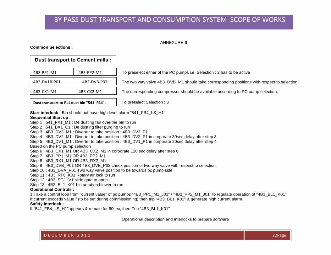
ANNEXURE-II Common Selections :
Dust transport to Cement mills :
To preselect either of the PC pumps i.e. Selection : 2 has to be active The two way valve 4B3_DVB_M1 should take corresponding positions with respect to selection. The corresponding compressor should be available according to PC pump selection.
To preselect Selection : 3
Start interlock : Bin should not have high level alarm "541_FB4_LS_H1" Sequential Start up : Step 1 : 541_FX1_M1 : De dusting fan over the bin to run Step 2 : 541_BX1_C1 : De dusting filter purging to run Step 3 : 4B3_DV3_M1 : Diverter to take position : 4B3_DV3_P1 Step 4 : 4B3_DV2_M1 : Diverter to take position : 4B3_DV2_P1 in corporate 30sec delay after step 3 Step 5 : 4B3_DV1_M1 : Diverter to take position : 4B3_DV1_P1 in corporate 30sec delay after step 4 Based on the PC pump selection Step 6 : 4B3_CX1_M1 OR 4B3_CX2_M1 in corporate 120 sec delay after step 6 Step 7 : 4B3_PP1_M1 OR 4B3_PP2_M1 Step 8 : 4B3_RX1_M1 OR 4B3_RX2_M1 Step 9 : 4B3_DVB_P01 OR 4B3_DVB_P02 check position of two way valve with respect to selection. Step 10 : 4B3_DVA_P01 Two way valve position to be towards pc pump side Step 11 : 4B3_RF6_K01 Rotary air lock to run Step 12 : 4B3_SG1_V1 slide gate to open Step 13 : 4B3_BL1_K01 bin aeration blower to run Operational Controls : 1 Take a control loop from "current value" of pc pumps "4B3_PP1_M1_J01" / "4B3_PP2_M1_J01" to regulate operation of "4B3_BL1_K01" If current excceds value " (to be set during commissioning) then trip "4B3_BL1_K01" & generate high current alarm. Safety Interlock : If "541_FB4_LS_H1"appears & remain for 60sec, then Trip "4B3_BL1_K01"
Operational description and Interlocks to prepare software
4B3-PP1-M1 4B3-PP2-M1
4B3-DV1B-P01 4B3-DVB-P02
4B3-CX1-M1 4B3-CX2-M1
Dust transport to PL1 dust bin "541_FB4".
BY PASS DUST TRANSPORT AND CONSUMPTION SYSTEM SCOPE OF WORKS
D E C E M B E R 2 0 1 1
Page 23
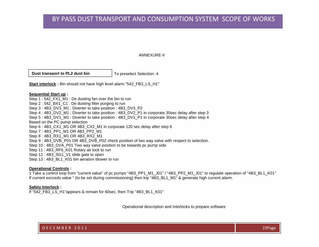
ANNEXURE-II To preselect Selection :4
Start interlock : Bin should not have high level alarm "542_FB3_LS_H1"
Sequential Start up : Step 1 : 542_FX1_M1 : De dusting fan over the bin to run Step 2 : 542_BX1_C1 : De dusting filter purging to run Step 3 : 4B3_DV3_M1 : Diverter to take position : 4B3_DV3_P2 Step 4 : 4B3_DV2_M1 : Diverter to take position : 4B3_DV2_P1 in corporate 30sec delay after step 3 Step 5 : 4B3_DV1_M1 : Diverter to take position : 4B3_DV1_P1 in corporate 30sec delay after step 4 Based on the PC pump selection Step 6 : 4B3_CX1_M1 OR 4B3_CX2_M1 in corporate 120 sec delay after step 6 Step 7 : 4B3_PP1_M1 OR 4B3_PP2_M1 Step 8 : 4B3_RX1_M1 OR 4B3_RX2_M1 Step 9 : 4B3_DVB_P01 OR 4B3_DVB_P02 check position of two way valve with respect to selection. Step 10 : 4B3_DVA_P01 Two way valve position to be towards pc pump side Step 11 : 4B3_RF6_K01 Rotary air lock to run Step 12 : 4B3_SG1_V1 slide gate to open Step 13 : 4B3_BL1_K01 bin aeration blower to run Operational Controls : 1 Take a control loop from "current value" of pc pumps "4B3_PP1_M1_J01" / "4B3_PP2_M1_J01" to regulate operation of "4B3_BL1_K01" If current excceds value " (to be set during commissioning) then trip "4B3_BL1_M1" & generate high current alarm. Safety Interlock : If "542_FB3_LS_H1"appears & remain for 60sec, then Trip "4B3_BL1_K01"
Operational description and Interlocks to prepare software
Dust transport to PL2 dust bin "542_FB3".
BY PASS DUST TRANSPORT AND CONSUMPTION SYSTEM SCOPE OF WORKS
D E C E M B E R 2 0 1 1
Page 24
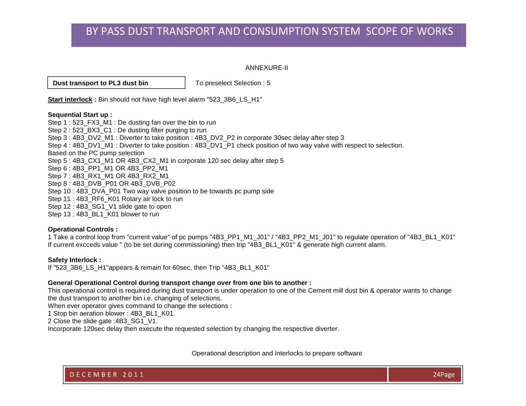
ANNEXURE-II To preselect Selection : 5
Start interlock : Bin should not have high level alarm "523_3B6_LS_H1" Sequential Start up : Step 1 : 523_FX3_M1 : De dusting fan over the bin to run Step 2 : 523_BX3_C1 : De dusting filter purging to run Step 3 : 4B3_DV2_M1 : Diverter to take position : 4B3_DV2_P2 in corporate 30sec delay after step 3 Step 4 : 4B3_DV1_M1 : Diverter to take position : 4B3_DV1_P1 check position of two way valve with respect to selection. Based on the PC pump selection Step 5 : 4B3_CX1_M1 OR 4B3_CX2_M1 in corporate 120 sec delay after step 5 Step 6 : 4B3_PP1_M1 OR 4B3_PP2_M1 Step 7 : 4B3_RX1_M1 OR 4B3_RX2_M1 Step 8 : 4B3_DVB_P01 OR 4B3_DVB_P02 Step 10 : 4B3_DVA_P01 Two way valve position to be towards pc pump side Step 11 : 4B3_RF6_K01 Rotary air lock to run Step 12 : 4B3_SG1_V1 slide gate to open Step 13 : 4B3_BL1_K01 blower to run Operational Controls : 1 Take a control loop from "current value" of pc pumps "4B3_PP1_M1_J01" / "4B3_PP2_M1_J01" to regulate operation of "4B3_BL1_K01" If current excceds value " (to be set during commissioning) then trip "4B3_BL1_K01" & generate high current alarm. Safety Interlock : If "523_3B6_LS_H1"appears & remain for 60sec, then Trip "4B3_BL1_K01" General Operational Control during transport change over from one bin to another : This operational control is required during dust transport is under operation to one of the Cement mill dust bin & operator wants to change the dust transport to another bin i.e. changing of selections. When ever operator gives command to change the selections : 1 Stop bin aeration blower : 4B3_BL1_K01. 2 Close the slide gate :4B3_SG1_V1. Incorporate 120sec delay then execute the requested selection by changing the respective diverter.
Operational description and Interlocks to prepare software
Dust transport to PL3 dust bin "523_3B6". "542_FB3".
BY PASS DUST TRANSPORT AND CONSUMPTION SYSTEM SCOPE OF WORKS
D E C E M B E R 2 0 1 1
Page 25
ANNEXURE-II
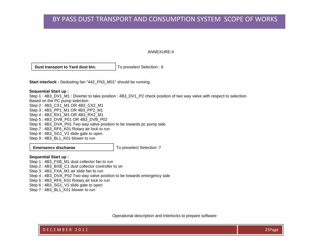
To preselect Selection : 6
Start interlock : Dedusting fan "442_FN3_M01" should be running. Sequential Start up : Step 1 : 4B3_DV1_M1 : Diverter to take position : 4B3_DV1_P2 check position of two way valve with respect to selection. Based on the PC pump selection Step 2 : 4B3_CX1_M1 OR 4B3_CX2_M1 Step 3 : 4B3_PP1_M1 OR 4B3_PP2_M1 Step 4 : 4B3_RX1_M1 OR 4B3_RX2_M1 Step 5 : 4B3_DVB_P01 OR 4B3_DVB_P02 Step 6 : 4B3_DVA_P01 Two way valve position to be towards pc pump side Step 7 : 4B3_RF6_K01 Rotary air lock to run Step 8 : 4B3_SG1_V1 slide gate to open Step 9 : 4B3_BL1_K01 blower to run To preselect Selection :7 Sequential Start up : Step 1 : 4B3_FXB_M1 dust collector fan to run Step 2 : 4B3_BXB_C1 dust collector controller to on Step 3 : 4B3_FXA_M1 air slide fan to run Step 4 : 4B3_DVA_P02 Two way valve position to be towards emergency side Step 5 : 4B3_RF6_K01 Rotary air lock to run Step 6 : 4B3_SG1_V1 slide gate to open Step 7 : 4B3_BL1_K01 blower to run
Operational description and Interlocks to prepare software
Dust transport to Yard dust bin. "542_FB3".
Emergency discharge "542_FB3".
BY PASS DUST TRANSPORT AND CONSUMPTION SYSTEM SCOPE OF WORKS
D E C E M B E R 2 0 1 1
Page 26
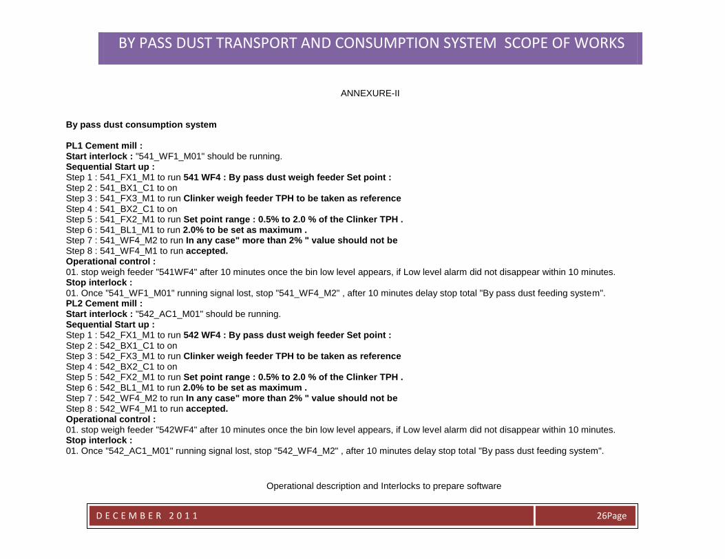
ANNEXURE-II By pass dust consumption system PL1 Cement mill : Start interlock : "541_WF1_M01" should be running. Sequential Start up : Step 1 : 541_FX1_M1 to run 541 WF4 : By pass dust weigh feeder Set point : Step 2 : 541_BX1_C1 to on Step 3 : 541_FX3_M1 to run Clinker weigh feeder TPH to be taken as reference Step 4 : 541_BX2_C1 to on Step 5 : 541_FX2_M1 to run Set point range : 0.5% to 2.0 % of the Clinker TPH . Step 6 : 541_BL1_M1 to run 2.0% to be set as maximum . Step 7 : 541_WF4_M2 to run In any case" more than 2% " value should not be Step 8 : 541_WF4_M1 to run accepted. Operational control : 01. stop weigh feeder "541WF4" after 10 minutes once the bin low level appears, if Low level alarm did not disappear within 10 minutes. Stop interlock : 01. Once "541_WF1_M01" running signal lost, stop "541_WF4_M2" , after 10 minutes delay stop total "By pass dust feeding system". PL2 Cement mill : Start interlock : "542_AC1_M01" should be running. Sequential Start up : Step 1 : 542_FX1_M1 to run 542 WF4 : By pass dust weigh feeder Set point : Step 2 : 542_BX1_C1 to on Step 3 : 542_FX3_M1 to run Clinker weigh feeder TPH to be taken as reference Step 4 : 542_BX2_C1 to on Step 5 : 542_FX2_M1 to run Set point range : 0.5% to 2.0 % of the Clinker TPH . Step 6 : 542_BL1_M1 to run 2.0% to be set as maximum . Step 7 : 542_WF4_M2 to run In any case" more than 2% " value should not be Step 8 : 542_WF4_M1 to run accepted. Operational control : 01. stop weigh feeder "542WF4" after 10 minutes once the bin low level appears, if Low level alarm did not disappear within 10 minutes. Stop interlock : 01. Once "542_AC1_M01" running signal lost, stop "542_WF4_M2" , after 10 minutes delay stop total "By pass dust feeding system".
Operational description and Interlocks to prepare software
BY PASS DUST TRANSPORT AND CONSUMPTION SYSTEM SCOPE OF WORKS
D E C E M B E R 2 0 1 1
Page 27
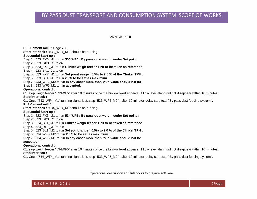
ANNEXURE-II PL3 Cement mill 3: Page 7/7 Start interlock : "533_WF4_M1" should be running. Sequential Start up : Step 1 : 523_FX3_M1 to run 533 WF5 : By pass dust weigh feeder Set point : Step 2 : 523_BX3_C1 to on Step 3 : 523_FX1_M1 to run Clinker weigh feeder TPH to be taken as reference Step 4 : 523_BX1_C1 to on Step 5 : 523_FX2_M1 to run Set point range : 0.5% to 2.0 % of the Clinker TPH . Step 6 : 523_BL1_M1 to run 2.0% to be set as maximum . Step 7 : 533_WF5_M2 to run In any case" more than 2% " value should not be Step 8 : 533_WF5_M1 to run accepted. Operational control : 01. stop weigh feeder "533WF5" after 10 minutes once the bin low level appears, if Low level alarm did not disappear within 10 minutes. Stop interlock : 01. Once "533_WF4_M1" running signal lost, stop "533_WF5_M2" , after 10 minutes delay stop total "By pass dust feeding system". PL3 Cement mill 4: Start interlock : "534_WF4_M1" should be running. Sequential Start up : Step 1 : 523_FX3_M1 to run 534 WF5 : By pass dust weigh feeder Set point : Step 2 : 523_BX3_C1 to on Step 3 : 524_BL1_M1 to run Clinker weigh feeder TPH to be taken as reference Step 4 : 524_RL1_M1 to run Step 5 : 523_BL1_M1 to run Set point range : 0.5% to 2.0 % of the Clinker TPH . Step 6 : 534_WF5_M2 to run 2.0% to be set as maximum . Step 7 : 534_WF5_M1 to run In any case" more than 2% " value should not be accepted. Operational control : 01. stop weigh feeder "534WF5" after 10 minutes once the bin low level appears, if Low level alarm did not disappear within 10 minutes. Stop interlock : 01. Once "534_WF4_M1" running signal lost, stop "533_WF5_M2" , after 10 minutes delay stop total "By pass dust feeding system".
Operational description and Interlocks to prepare software
BY PASS DUST TRANSPORT AND CONSUMPTION SYSTEM SCOPE OF WORKS
D E C E M B E R 2 0 1 1
Page 28
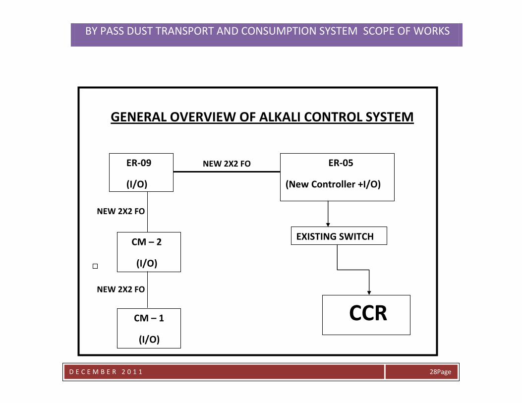
GENERAL OVERVIEW OF ALKALI CONTROL SYSTEM
NEW 2X2 FO
NEW 2X2 FO
ER-09
(I/O)
ER-05
(New Controller +I/O)
CM – 2
(I/O)
CM – 1
(I/O)
EXISTING SWITCH
CCR
ER-09
(I/O)
CM – 2
(I/O)
CM – 1
(I/O)
NEW 2X2 FO
BY PASS DUST TRANSPORT AND CONSUMPTION SYSTEM SCOPE OF WORKS
D E C E M B E R 2 0 1 1
Page 29
Please find the descriptions of interconnecting jobs as follows :
Interconnection jobs :
The Contractor must have to complete all the erection & installation while Plant in operation.
The interconnecting job/s is / are such an activity where in the New project plant will be hooked up with existing plant section.
Hence QCC has to stop such particular plant section during the interconnection activity, to allow the Contractor to perform the
interconnection job. As such an activity involves the Plant stoppage the activity should be well time framed to complete within stipulated time
for each of such interconnection jobs as described below :
01. Interconnection at PL1 Cement mill discharge air slide point : 8hrs.
02. Interconnection at PL2 Cement mill discharge air slide point : 8hrs.
03. Interconnection at PL3 Cement mill 3 discharge air slide point : 8hrs.
04. Interconnection at PL3 Cement mill 4 discharge air slide point : 8hrs.
All the interconnections at Cement mills has to be performed during Preventive maintenance stoppages.
05. Interconnections at Existing PL3 Alkali dust bin extraction point : 16hrs.
Pre Requirements :
This activity will be arranged upon :
A. Completion of erection of New Project equipments along with no load trial runs of all the erected equipments.
BY PASS DUST TRANSPORT AND CONSUMPTION SYSTEM SCOPE OF WORKS
D E C E M B E R 2 0 1 1
Page 31
B. The erection of the New Emergency truck discharge system should be completed.
This activity involves :
01.dismantling of existing telescopic chute & rotary air lock.
02.Re installation of the telescopic chute at the discharge of the new air slide for the emergency truck discharge.
03. Install the chute & new two way valve.
04. Connect the air slide feed chute towards PC pump side & Emergency truck discharge side.
06. a . Final connection for the existing dust transport line from PL1 to newly installed pipe line for PL3 main
Bin.
b. Final connection from the Newly installed line after diverter to existing PL1 dust transport line.
a & b are Parallel activities : 8hrs.
07. Final connection for the existing dust transport line from PL2 to newly installed pipe line for PL3 main
Bin. 8hrs.
Pre Requirements for interconnections 06 & 07 : Successful operation of New system both towards PC pump side & emergency truck
discharge side is must.
Delay Compensation in the completion of the Interconnection jobs :
Each one complete hour delay will be subjected to penalty of 1% of the total contract price.
Defect s & its Rectification :
Defects in the contractor supplied fabricated items :
Intermediate Inspection : During the manufacturing stage Contractor shall invite QCC for the inspection of fabricated items at his
premises. Such fabricated items quantity should be minimum 50% of the total quantity. Upon the completion of the inspection, QCC will
notify the defects if any that are found in the fabricated items. The Contractor should make note of defects identified by QCC & have to
BY PASS DUST TRANSPORT AND CONSUMPTION SYSTEM SCOPE OF WORKS
D E C E M B E R 2 0 1 1
Page 31
rectify before proceeding to subsequent fabrication. Contractor must also take proper care to avoid such defects in subsequent
fabricated items.
Final Inspection : Upon the completion of the fabrication of all the items, Contractor should request QCC for final inspection of the
fabricated items before delivery to QCC site.
The Contractor should arrange for the safe & secured transport of all the items to the QCC site under his responsibility. The Contractor
must be aware & comply with transport requirement with respect to size of the items transported.
Erection Defects :
During the progress of the erection works, periodically QCC team will be notifying the defects & same will be brought to the knowledge
of Erection Contractor through the defect lists. Upon the severity of such identified defects from the QCC point of view, Contractor must
take necessary steps to make the defect good.
Commissioning defects :
These defects will be identified during the commissioning of the New Project & same will be notified to the Erection Contractor through
the defect lists. The Contractor must rectify all such identified defects.
Any leakages found in the installed transport pipe line will be also counted as defect towards the Erection Contractor & same must be
rectified . Even though such line has not been installed by the Erection contractor but where as it is being a part of project.
The Erection Contractor must supply the skilled man power for the rectification of equipment defects.