Embed Size (px)
Citation preview
NOTICE: This publication is available digitally on the AFDPO WWW site at:http://afpubs.hq.af.mil.
BY ORDER OF THE SECRETARY OF THE AIR FORCE
AIR FORCE MANUAL 33-214, VOLUME 2
21 SEPTMEBER 2001
Communications and Information
EMISSION SECURITY COUNTERMEASURESREVIEWS
OPR: HQ AFCA/TCBA (Mr. Dwight Bohl) Certified by: HQ USAF/SCXX(Col Terry G. Pricer, Sr.)
Pages: 188Distribution: F
This Air Force manual (AFMAN) implements Air Force Policy Directive (AFPD) 33-2, Information Pro-tection (will become “Information Assurance [IA]”). This AFMAN provides guidance for conductingemission security (EMSEC) countermeasures reviews for information systems, communications systems,and cryptographic equipment according to Air Force Instruction (AFI) 33-203, Emission Security. As partof IA, this AFMAN implements the National Security Telecommunications and Information SystemsSecurity Memorandum (NSTISSM)/TEMPEST 2-95, (FOUO) RED/BLACK Installation Guidance (U).Use this manual in conjunction with Air Force Systems Security Instruction (AFSSI) 7010, (S) EmissionSecurity Assessments (U) (will become AFMAN 33-214, Volume 1). Use of extracts is encouraged. Addi-tional security instructions and manuals are listed on the Air Force publications Web site at URL: http://afpubs.hq.af.mil under electronic publications. Air Force Directory (AFDIR) 33-303, Compendium ofCommunications and Information Terminology, explains other terms. Direct technical questions on thecontents of this manual to Headquarters Air Force Communications Agency (HQ AFCA/TCBA-CTTA),203 W. Losey Street, Room 2000, Scott AFB IL 62225-5222. Send recommended changes or commentsto HQ AFCA/ITPP, 203 W. Losey Street, Room 1100, Scott AFB IL 62225-5222, through appropriatechannels, using AF Form 847, Recommendation for Change of Publication. Provide an informationcopy to Headquarters United States Air Force (HQ USAF/SCMI), 1250 Air Force Pentagon, WashingtonDC 20330-1250, and HQ AFCA/TCBA-CTTA. The use of the name or mark of any specific manufac-turer, commercial product, commodity, or service in this publication does not imply endorsement by theAir Force. See Attachment 1 for a glossary of references and supporting information. Maintain and dis-pose of records created as a result of prescribed processes according to AFMAN 37-139, Records Dispo-sition Schedule (will become AFMAN 33-322, Volume 4). The Paperwork Reduction Act of 1980 (PublicLaw [P.L.] 96-511) and AFI 33-360, Volume 2, Forms Management Program affect this publication.NOTE: This AFMAN replaces Air Force Systems Security Manual (AFSSM) 7011 dated 1 May 1998.
Chapter 1—INTRODUCTION 8
1.1. General. ...................................................................................................................... 8
1.2. Emission Security Process. ........................................................................................ 8

Report Documentation Page
Report Date 21 Sep 2001
Report Type N/A
Dates Covered (from... to) -
Title and Subtitle Air Force Manual 33-214 Volume 2 Communications andInformation Emission Security Countermeasures Reviews
Contract Number
Grant Number
Program Element Number
Author(s) Project Number
Task Number
Work Unit Number
Performing Organization Name(s) and Address(es) Air Force Communications and Information Center (HQAFCA/XPXP) Pentagon Washington D C 20330-1250
Performing Organization Report Number
Sponsoring/Monitoring Agency Name(s) and Address(es)
Sponsor/Monitor’s Acronym(s)
Sponsor/Monitor’s Report Number(s)
Distribution/Availability Statement Approved for public release, distribution unlimited
Supplementary Notes
Abstract
Subject Terms
Report Classification unclassified
Classification of this page unclassified
Classification of Abstract unclassified
Limitation of Abstract UU
Number of Pages 188

2 AFMAN33-214V2 21 SEPTMEBER 2001
1.3. Emission Security Countermeasures Reviews. .......................................................... 9
1.4. Completing the Countermeasures Reviews. .............................................................. 9
1.5. Maintaining Emission Security. ................................................................................. 9
1.6. Emission Security Testing. ........................................................................................ 10
1.7. Emission Security Countermeasures. ........................................................................ 10
Chapter 2—THE INFORMATION SYSTEMS COUNTERMEASURES REVIEW 11
2.1. Introduction. ............................................................................................................... 11
2.2. Systematic Approach. ................................................................................................ 11
2.3. Application Requirement. .......................................................................................... 12
2.4. Determine the Inspectable Space. .............................................................................. 12
2.5. Identify Equipment TEMPEST Characteristics. ........................................................ 13
2.6. Selecting Countermeasures. ....................................................................................... 14
Table 2.1. Countermeasures Requirements. .............................................................................. 14
2.7. Estimating Cost. ......................................................................................................... 15
2.8. Analyzing the Results. ............................................................................................... 15
2.9. Documenting the Results. .......................................................................................... 15
2.10. Completing the Information Systems Countermeasures Review. ............................. 16
Chapter 3—THE COMMUNICATIONS SYSTEMS COUNTERMEASURES REVIEW 17
3.1. Introduction. ............................................................................................................... 17
3.2. Installation Requirement. ........................................................................................... 17
3.3. Transmitting Equipment. ........................................................................................... 17
Table 3.1. Separation Requirements for Transmitters. .............................................................. 17
Table 3.2. Separation Requirements for Signal and Control Wire Lines. ................................. 18
3.4. Special Items. ............................................................................................................. 18
3.5. Estimating Cost. ......................................................................................................... 20
3.6. Analyzing the Results. ............................................................................................... 20
3.7. Documenting the Results. .......................................................................................... 20
3.8. Completing the Information Systems Countermeasures Review. ............................. 20
Chapter 4—THE CRYPTOGRAPHIC EQUIPMENT COUNTERMEASURES REVIEW 21
4.1. Introduction. ............................................................................................................... 21
4.2. Installation Requirement. ........................................................................................... 21

AFMAN33-214V2 21 SEPTMEBER 2001 3
4.3. Secure Telephone Unit-III (STU-III), Secure Terminal Equipment (STE), and Like Items. .......................................................................................................... 21
4.4. Cryptographic System KIV-7. ................................................................................... 21
4.5. FORTEZZA For Classified (FFC). ............................................................................ 22
4.6. Electronic Key Management System (EKMS). ......................................................... 22
4.7. All Other Cryptographic Equipment. ......................................................................... 23
4.8. Changing From Unclassified to Classified Processing. ............................................. 23
4.9. Analyzing the Results. ............................................................................................... 24
4.10. Documenting the Results. .......................................................................................... 24
4.11. Completing the Cryptographic Equipment Countermeasures Review. ..................... 24
Chapter 5—COMPLETING THE COUNTERMEASURES REVIEWS 25
5.1. Introduction. ............................................................................................................... 25
5.2. Classification Marking. .............................................................................................. 25
5.3. Authentication Documentation. ................................................................................. 25
5.4. Tracking and Address Information. ........................................................................... 25
5.5. Validating the Countermeasures Reviews. ................................................................ 25
5.6. Inform the User. ......................................................................................................... 26
5.7. Date. ........................................................................................................................... 27
5.8. Apply the Countermeasures. ...................................................................................... 27
5.9. Emission Security Inspection. .................................................................................... 27
5.10. Waivers. ..................................................................................................................... 27
5.11. Emission Security Certification. ................................................................................ 27
5.12. File Copy. ................................................................................................................... 27
5.13. Reassessments and Recertifications. .......................................................................... 27
Chapter 6—EMISSION SECURITY MAINTENANCE 28
6.1. Maintaining Equipment and Countermeasures. ......................................................... 28
6.2. Maintenance Requirements. ....................................................................................... 28
6.3. Ensuring the Integrity of TEMPEST-Certified Equipment. ...................................... 28
6.4. When Not to Maintain the TEMPEST Integrity. ....................................................... 29
6.5. Transportation of Equipment for Maintenance. ......................................................... 30
6.6. Repair Facilities. ........................................................................................................ 30
6.7. Emission Security Documentation-of-Maintenance Requirements. .......................... 30

4 AFMAN33-214V2 21 SEPTMEBER 2001
6.8. Disposing of TEMPEST-Certified Equipment. ......................................................... 30
Chapter 7—EMISSION SECURITY TESTING 31
7.1. Purpose of Testing. .................................................................................................... 31
7.2. Kinds of Emission Security Tests. ............................................................................. 31
7.3. When to Test. ............................................................................................................. 31
7.4. Requesting a Test. ...................................................................................................... 32
7.5. Emission Security Test Results. ................................................................................. 32
Chapter 8—EMISSION SECURITY COUNTERMEASURES 33
8.1. Introduction. ............................................................................................................... 33
8.2. Fundamentals of Compromising Emanations. ........................................................... 33
8.3. Requirement -- Contain Compromising Emanations. ................................................ 35
8.4. Containing Radiated Compromising Emanations. ..................................................... 35
8.5. Containing Conducted Compromising Emanations. ................................................. 35
8.6. RED and BLACK Concept. ....................................................................................... 36
8.7. RED and BLACK Equipment. ................................................................................... 36
8.8. Countermeasure -- RED Equipment and BLACK Equipment Separation. ............... 36
8.9. Countermeasure -- RED Equipment and BLACK Wire Line Separation. ................ 38
8.10. Countermeasure -- RED Equipment and BLACK Power Line Separation. .............. 39
8.11. Countermeasure -- RED Equipment and BLACK Signal Ground Wire Separation. 39
8.12. Countermeasure -- RED Equipment and Fortuitous Conductor Separation. ............. 40
8.13. Countermeasure -- Low-Level Signaling. ................................................................. 41
8.14. Signal Lines. .............................................................................................................. 42
8.15. RED and BLACK Wire Lines. .................................................................................. 42
8.16. Countermeasure -- RED Wire Line and BLACK Equipment Separation. ................ 42
8.17. Countermeasure -- RED Wire Line and BLACK Wire Line Separation. .................. 43
8.18. Countermeasure -- RED Wire Line and BLACK Power Line Separation. ............... 44
8.19. Countermeasure -- RED Wire Line and BLACK Signal Ground Wire Separation. . 45
8.20. Countermeasure -- RED Wire Line and Fortuitous Conductor Separation. .............. 46
8.21. Shielded Signal Wire Lines. ...................................................................................... 47
8.22. Fiber Optic Signal Lines. ........................................................................................... 47
8.23. Countermeasure -- Shielded RED Wire Lines. .......................................................... 48
8.24. Countermeasure -- Shielded BLACK Wire Lines. .................................................... 49

AFMAN33-214V2 21 SEPTMEBER 2001 5
8.25. Countermeasure -- BLACK Wire Line Isolation. ...................................................... 50
8.26. RED and BLACK Power. .......................................................................................... 52
8.27. Countermeasure -- RED Power. ................................................................................ 53
8.28. Countermeasure -- Filtered RED Power. ................................................................... 53
8.29. Countermeasure -- RED Power Line and BLACK Equipment Separation. .............. 56
8.30. Countermeasure -- RED Power Line and BLACK Wire Line Separation. ............... 57
8.31. Countermeasure -- RED Power Line and BLACK Power Line Separation. ............. 58
8.32. Countermeasure -- RED Power Line and BLACK Signal Ground Wire Separation. 59
8.33. Countermeasure -- RED Power Line and Fortuitous Conductor Separation. ............ 60
8.34. Introduction to Grounds. ............................................................................................ 61
8.35. RED and BLACK Signal Grounds. ........................................................................... 63
8.36. Countermeasure -- RED Signal Ground Wire and BLACK Equipment Separation. 64
8.37. Countermeasure -- RED Signal Ground Wire and BLACK Wire Line Separation. . 65
8.38. Countermeasure -- RED Signal Ground Wire and BLACK Power Line Separation. 66
8.39. Countermeasure -- RED Signal Ground Wire and BLACK Signal Ground Wire Separation. ........................................................................................................ 66
8.40. Countermeasure -- RED Signal Ground Wire and Fortuitous Conductor Separation. 67
8.41. Countermeasure -- BLACK Signal Ground Wire and BLACK Equipment Separation. 68
8.42. Countermeasure -- BLACK Signal Ground Wire and BLACK Wire Line Separation. 69
8.43. Countermeasure -- BLACK Signal Ground Wire and BLACK Power Line Separation. 70
8.44. Countermeasure -- BLACK Signal Ground Wire and Fortuitous Conductor Separation. 70
8.45. Ground Checks. ......................................................................................................... 71
8.46. Fortuitous Conductors. ............................................................................................... 71
8.47. Countermeasure -- Fortuitous Conductor Isolation. .................................................. 72
8.48. Distribution Facilities. ............................................................................................... 73
8.49. Countermeasure -- Distribution Facility Installation. ................................................ 73
8.50. Countermeasure -- TEMPEST-Certified Equipment. ................................................ 79
8.51. Countermeasure -- Shielding. .................................................................................... 79
8.52. Countermeasure -- BLACK Telephone Systems. ...................................................... 81
8.53. Countermeasure -- BLACK Intercom and Public Address Systems. ........................ 81
8.54. Countermeasure -- BLACK Local Area Networks. ................................................... 82
8.55. Countermeasure -- Comfort Music Systems. ............................................................. 84
8.56. Countermeasure -- BLACK Cable Television Systems. ........................................... 84

6 AFMAN33-214V2 21 SEPTMEBER 2001
8.57. Countermeasure -- BLACK Television-Video Cassette Recorder (VCR) Systems. . 85
8.58. Secure Telephones. .................................................................................................... 86
8.59. Countermeasure -- Timing and Control Lines Installation Guidance. ....................... 86
8.60. Countermeasure -- Utility Control Cables. ................................................................ 86
8.61. Operating and Maintenance Practices. ....................................................................... 86
8.62. Control of RED Equipment. ...................................................................................... 87
8.63. Information Collections, Records, and Forms. .......................................................... 87
Attachment 1—GLOSSARY OF TERMS AND SUPPORTING INFORMATION 88
Attachment 2—TRANSPORTABLE SYSTEMS IN A TACTICAL ENVIRONMENT 93
Attachment 3—AIRCRAFT 95
Attachment 4—DOCUMENTING THE COUNTERMEASURES REVIEWS 97
Attachment 5—GENERIC ZONE ASSIGNMENTS (GZA) 103
Attachment 6—FACILITY ZONE A, EQUIPMENT ZONE A 104
Attachment 7—FACILITY ZONE B, EQUIPMENT ZONE A 108
Attachment 8—FACILITY ZONE C, EQUIPMENT ZONE A 112
Attachment 9—FACILITY ZONE A, EQUIPMENT ZONE B 115
Attachment 10—FACILITY ZONE B, EQUIPMENT ZONE B 124
Attachment 11—FACILITY ZONE C, EQUIPMENT ZONE B 132
Attachment 12—FACILITY ZONE A, EQUIPMENT ZONE C 139
Attachment 13—FACILITY ZONE B, EQUIPMENT ZONE C 148
Attachment 14—FACILITY ZONE C, EQUIPMENT ZONE C 156
Attachment 15—EXAMPLE OF EMISSION SECURITY REQUIREMENTS MEMORANDUM 164
Attachment 16—EXAMPLE OF EMISSION SECURITY CERTIFICATION MEMORANDUM 167
Attachment 17—EMISSION SECURITY TESTING 168

AFMAN33-214V2 21 SEPTMEBER 2001 7
Attachment 18—SHIELDED CABLES 172
Attachment 19—FILTERS AND ISOLATORS 173
Attachment 20—MAINTENANCE OF SHIELDED ENCLOSURES 178
Attachment 21—APPLYING ADMINISTRATIVE COMMUNICATIONS COUNTERMEASURES 180
Attachment 22—AIR FORCE FORM 4170, EMISSION SECURITY ASSESSMENTS 184

8 AFMAN33-214V2 21 SEPTMEBER 2001
Chapter 1
INTRODUCTION
1.1. General. A major goal of IA is to assure the availability, integrity, and confidentiality of informa-tion and information systems. To this end, the IA disciplines of communications security (COMSEC),computer security, and EMSEC have, of necessity, become interdependent. EMSEC mostly supports the“confidentiality” requirement.
1.1.1. The objective of EMSEC is to contain compromising emanations within an inspectable space(IS). This is accomplished by identifying requirements from the broader view of IA and providing theappropriate protection at the least possible cost. Key to this is a partnership between the IA office andthe user.
1.1.1.1. The wing IA office assesses the need for EMSEC as part of IA; it determines the requiredcountermeasures; advises commanders of vulnerabilities, threats, and risks; and recommends apractical course of action.
1.1.1.2. The user identifies the systems that will process classified and, in some instances, unclas-sified information; the volume, relative sensitivity, and perishability of the information; the phys-ical control measures in effect around the area that will process classified information; and appliesidentified countermeasures. The term, "classified information," as used in this AFMAN, includesinstances of unclassified information. Those instances are defined in AFSSI 7010 (will becomeAFMAN 33-214, Volume 1).
1.1.2. An understanding of the EMSEC problem is essential to meeting EMSEC goals. The EMSECproblem is explained in AFSSI 7010 (will become AFMAN 33-214, Volume 1).
1.1.3. The national managers used risk management principles to develop the minimum requirementsidentified in this AFMAN. Since the risk has been accepted at the national level, no further risk forEMSEC can be accepted.
1.2. Emission Security Process. An important part of IA is the certification and accreditation (C&A)process. The C&A process addresses vulnerabilities and threats with the goal of reducing the risk to anacceptable level. EMSEC is part of the C&A process. The EMSEC process determines protective mea-sures that will deny unauthorized persons information collected from the intercept and analysis of emana-tions from information systems processing classified information. The EMSEC assessment determines ifthe threat is sufficient to require an EMSEC countermeasures review for information systems, communi-cations systems, and cryptographic equipment. Following are the major steps and where they fit into theC&A process.
1.2.1. Basic EMSEC Process:
1.2.1.1. The user contacts the wing IA office whenever classified information will be processed.The user must do this before processing any such information.
1.2.1.2. The wing IA office makes the information systems, communications systems, and cryp-tographic equipment assessments to determine the need for EMSEC countermeasures andrequired IA countermeasures. This is the first half of determining the EMSEC portion of the secu-rity policy for the C&A of the information system.

AFMAN33-214V2 21 SEPTMEBER 2001 9
1.2.1.3. When needed, the wing IA office makes the information systems, communications sys-tems, or cryptographic equipment countermeasures reviews to determine specific EMSEC coun-termeasures based on the threat for that location. This is the second half of determining theEMSEC portion of the security policy for the C&A of the information system.
1.2.1.4. The selection of EMSEC countermeasures is validated by the Air Force Certified TEM-PEST Technical Authority (CTTA) at HQ AFCA.
1.2.1.5. The required countermeasures are given to the user for application or implementation.
1.2.1.6. The wing IA office inspects the application of countermeasures for correctness and effec-tiveness. The inspection is made during the security test and evaluation task of the C&A.
1.2.1.7. The wing IA office certifies the information system, communications system, or crypto-graphic equipment meets EMSEC requirements as part of the certification phase of the C&A.
1.2.2. The Different EMSEC Problems. The means for escape of compromising emanations are dif-ferent for information systems, communications systems, and cryptographic systems; therefore, theEMSEC process is established to treat each of these separately to address their individual hazards.
1.2.2.1. The information systems countermeasures review determines the control of compromis-ing emanations required for information systems that process classified information.
1.2.2.2. The communications systems countermeasures review determines the countermeasuresrequired for information systems that process classified information close to communications sys-tems.
1.2.2.3. The cryptographic equipment countermeasures review determines the countermeasuresrequired for cryptographic equipment.
1.3. Emission Security Countermeasures Reviews. Like the EMSEC assessments, there are threeEMSEC countermeasures reviews: information systems, communications systems, and cryptographicequipment. Complete each review separate from the others and without regard to the outcome of the oth-ers. These reviews produce the EMSEC requirements for the information system under review. Documentthe requirements on AF Form 4170, Emission Security Assessments/Emission Security Countermea-sures Reviews. The AF Form 4170 documents EMSEC requirements and is the basis for making theEMSEC inspection; it is not the result of an EMSEC inspection.
1.3.1. Information Systems. Follow the guidance in Chapter 2 to make the information systemscountermeasures review.
1.3.2. Communications Systems. Follow the guidance in Chapter 3 for the communications systemscountermeasures review.
1.3.3. Cryptographic Equipment. Follow the guidance in Chapter 4 for the cryptographic equipmentcountermeasures review.
1.4. Completing the Countermeasures Reviews. After selecting and documenting the needed counter-measures, complete documenting the countermeasures reviews. Classification marking, authentication,tracking, validation, informing the user, inspection, certification, and filing procedures are in Chapter 5.

10 AFMAN33-214V2 21 SEPTMEBER 2001
1.5. Maintaining Emission Security. The user must properly maintain the EMSEC countermeasuresand equipment used to process classified information. Follow the guidance in Chapter 6.
1.6. Emission Security Testing. When EMSEC testing is needed to meet EMSEC requirements, followthe guidance in Chapter 7 to request EMSEC testing.
1.7. Emission Security Countermeasures. The numerous countermeasures used in EMSEC are dis-cussed in Chapter 8. For each countermeasure there is a discussion of the problem requiring a counter-measure, what the countermeasure is, what the countermeasure does, what conditions negate the need forthe countermeasure, how to apply the countermeasure when required, and alternatives.

AFMAN33-214V2 21 SEPTMEBER 2001 11
Chapter 2
THE INFORMATION SYSTEMS COUNTERMEASURES REVIEW
2.1. Introduction. When the need to control compromising emanations is indicated by the informationsystems assessment, make an information systems countermeasures review to determine the required con-trol of compromising emanations countermeasures. This review is based on the use of non-TEM-PEST-certified equipment. TEMPEST-certified equipment is a countermeasure. The Air Force CTTAmust validate all requirements for TEMPEST-certified equipment. The possibility of the intercept of com-promising emanations is a function of many variables. Chief among these are the:
2.1.1. Amount of inspectable space surrounding the systems processing classified information.
2.1.2. Radiation characteristics of the systems processing classified information.
2.1.3. Radio frequency attenuation offered by the facility containing the systems processing classifiedinformation.
2.1.4. Fortuitous conductors near the systems processing classified information.
2.2. Systematic Approach. The Air Force uses a systematic approach to determine the required coun-termeasures and the degree to which they are applied. Consider the following:
2.2.1. Location. This is the geographic location where the information is processed, the proximity toestablishments of countries listed in Annex C of National Security Telecommunications and Informa-tion Systems Security Instruction (NSTISSI) 7000, (C) TEMPEST Countermeasures for Facilities(U), and other countries that could pose a technical threat to the information.
2.2.2. Volume of Information Processed. This is the total volume and the percentage or volume ofprocessed information at the UNCLASSIFIED, SENSITIVE, CONFIDENTIAL, SECRET, and TOPSECRET level.
2.2.3. Sensitivity of Information Processed. This is the sensitivity of the processed information (e.g.,Department of Energy - Restricted Data; Director of Central Intelligence - Sensitive CompartmentedInformation [SCI]; Joint Staff - Single Integrated Operational Plan). This is useful in determining thelikelihood that an adversary may target the facility.
2.2.4. Perishability of Information Processed. The processed information has either long-term value(e.g., strategic) or short-term value (e.g., tactical). Long-term information requires a more conserva-tive approach to selecting countermeasures than short-term information.
2.2.5. Physical Control. This is the physical and access control for the facility and area containing thesystem under review. This includes guards (number, hours of posting, patrols, etc.), badging, controlof access to the facility, alarms, procedures to monitor or control uncleared or unauthorized personnelincluding custodial and janitorial personnel, vending personnel, and telephone and power maintainersand installers. Determine the level of authority that exists for the inspection or removal of personnelwho could potentially exploit compromising emanations. Examine the posting of warning signs andthe implementation of procedures in effect to exercise control over parking and other areas adjacent toor in close proximity to the facility containing the system under review.

12 AFMAN33-214V2 21 SEPTMEBER 2001
2.2.6. TEMPEST Profile of Equipment. This is the generic or actual TEMPEST profile informationfor each equipment or system used to process classified information in the facility. Consider existingon-site EMSEC test results for the facility.
2.3. Application Requirement. Apply control of compromising emanations countermeasures accordingto the instructions in this chapter. The requirements are separate from other EMSEC requirements (com-munications systems and cryptographic equipment). Apply them even when there are no other EMSECrequirements. Tactical equipment and aircraft are excluded from this universal requirement. See Attach-ment 2 and Attachment 3 for transportable systems in a tactical environment and aircraft-unique require-ments.
2.4. Determine the Inspectable Space. When it is required to control compromising emanations, con-tain them within the inspectable space. In the planning stages for large projects, the user contacts the IAoffice as soon as possible. When classified information is to be processed, the IA office contacts theinstallation’s information security program manager or reviews Department of Defense (DoD) Regulation5200.1-R, Information Security Program, January 1977, for secure room construction standards, and oth-ers responsible for constructing or modifying a building. Even for projects as small as the acquisition of apersonal computer (PC), the user consults with the IA office early to identify physical security require-ments. Adopt measures to meet the security requirements that are effective, practical, and compatible withlocal policies and provisions.
2.4.1. The IA Office. The IA office identifies the inspectable space by using the guidance in para-graph 2.4.3. and indicates it on a map (see Attachment 4). Attach the map to the AF Form 4170, doc-umenting the information systems, communications systems, and cryptographic equipmentcountermeasures reviews. The map of the inspectable space is usually unclassified.
2.4.2. The CTTA. The CTTA reviews the map and validates the identified inspectable space as com-plying with national guidance. This determines the inspectable space. The Defense IntelligenceAgency (DIA/DAC-2A) determines inspectable space for DIA-accredited SCI facilities.
2.4.3. Identifying the inspectable space. The inspectable space is not intended to prevent an adversaryfrom making a technical attack but rather to identify the area where the chance of discovery is toorisky thereby deterring an adversary. Therefore, the inspectable space takes advantage of existingphysical security.
2.4.3.1. inspectable space is defined as “the three-dimensional space surrounding systems thatprocess classified or sensitive information within which TEMPEST exploitation is not consideredpractical or where legal authority to identify or remove a potential TEMPEST exploitation exists.”This definition is explained as follows:
2.4.3.1.1. Three-Dimensional Space. This term means up and down as well as around.
2.4.3.1.2. Not Practical. What is considered not practical? Put yourself in the place of a spymanager. You have this person with a high level of technical knowledge, trained in testing andanalysis, and 3 to 5 years of experience. You equip this person with some equipment (not spe-cially built but it is expensive in total cost; several receivers, demodulators, oscilloscope,video monitor, a couple of recorders, and accessories). So, how much risk are you going totake with this person? It is extremely unlikely that you will direct this person to set up a TEM-PEST-exploitation operation on a military installation. If the information is vital and this is the

AFMAN33-214V2 21 SEPTMEBER 2001 13
only way to get the information, you might, but it is very risky because the person will have toget very close since they will apply many countermeasures. So, as the IA office, keep this inmind when identifying inspectable space. Also, it may be possible to include exposed placesoutside a military installation as inspectable space since the adversary does not want to be dis-covered.
2.4.3.1.3. Legal Authority to Identify or Remove a Potential TEMPEST Exploitation. TheUnited States (U.S.) Government certainly has that authority on every base in the UnitedStates, its trust territories, and possessions (hereafter called the United States), but, what aboutbases under foreign control? On some bases under foreign control, the U.S. Government doeshave the authority to identify or remove, in concert with the host nation’s security people. Thatcounts as inspectable space. What about a base in a country where the U.S. Government has allthat but the host country has areas where U.S. personnel are not authorized to visit, either notat all or not without prior notice. The key here is access. If prior notice of less than one hour isrequired, then the U.S. Government has access. If prior notice of more than one hour isrequired, then the U.S. Government does not have access and that area is not considered asinspectable space.
2.4.3.2. Take advantage of circumstances that keep adversaries away or increase either the physi-cal distance or the zone rating.
2.4.3.2.1. For radiated compromising emanations, 6 inches of reinforced concrete provides anominal 20 decibels (dB) of attenuation. When the inspectable space is defined in distance, asteel pan, poured concrete floor, or ceiling will provide about 20 dB of attenuation adding onezone level to the inspectable space in that direction. That is, when the inspectable space is 1meter but less than 20 meters (Zone A) the inspectable space becomes Zone B or when theinspectable space is 20 meters but less than 100 meters (Zone B) the inspectable spacebecomes Zone C, etc. This is because the zones are 16 dB apart. An 8-inch thick reinforcedconcrete wall offers about 12 dB of attenuation or about 3/4 of a zone. Cinder block and brickwalls offer about 4 dB of attenuation or about 1/4 of a zone.
2.4.3.2.2. For conducted compromising emanations, look for things that prevent access toconductors (like the building is totally within the inspectable space so heating and air condi-tioning ducts and water pipes are not accessible) or would reduce the magnitude of any com-promising emanations on a conductor.
2.4.3.3. Identify the inspectable space boundary and indicate it on the map. Base the decision onhow willing an adversary is to risk an asset and U.S. Government access to areas considered asinspectable space.
2.4.4. Multiple Use of the inspectable space Map. Once the inspectable space is determined and themap made, it can be used for all other countermeasures reviews of systems within that inspectablespace.
2.4.5. When Changes Occur. Reaccomplish all information systems countermeasures reviews whenthe inspectable space shrinks or expands.
2.5. Identify Equipment TEMPEST Characteristics. The methods for identifying the equipmentTEMPEST characteristics are listed in preferred sequence. Ask your major command (MAJCOM) IAoffice for assistance if you do not have the information you need.
14 AFMAN33-214V2 21 SEPTMEBER 2001
2.5.1. Equipment TEMPEST Zone Rating. Use the TEMPEST zone assignment for information pro-cessing equipment to find the equipment TEMPEST zone ratings. Obtain this from the MAJCOM IAoffice.
2.5.2. TEMPEST Level Rating. Use the level assignment (I, II, or III) for the system based onEMSEC test results. The equipment radiation TEMPEST zone (ERTZ) may be used if known.
2.5.3. Generic Zone Assignment. HQ AFCA/TCBA developed the generic zone assignment and is anaverage of like equipment. Use Attachment 5 for the zone assignment for the kind of equipment used.
2.5.4. Other Guidance. If the equipment under review is not identified in any of the above sources,use the category "All Other RED Equipment."
2.6. Selecting Countermeasures.
2.6.1. Radiated Compromising Emanations. Using the equipment TEMPEST characteristics, identifythe amount of inspectable space required to contain radiated compromising emanations within theinspectable space.
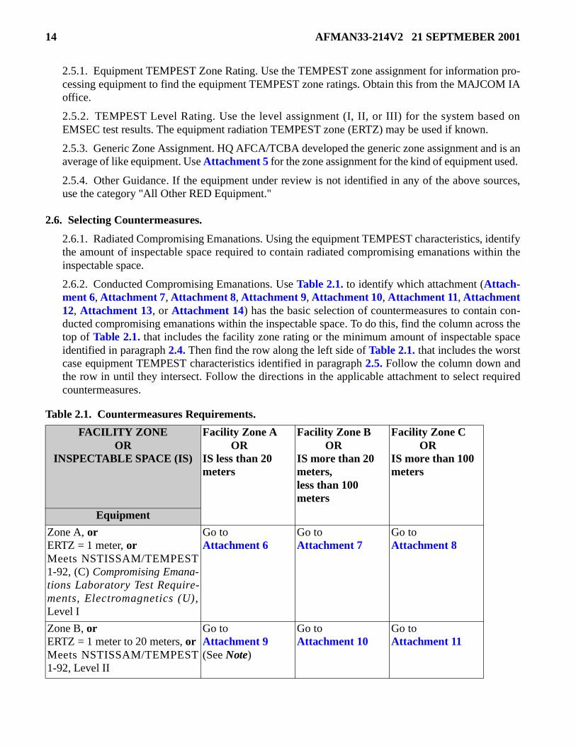
2.6.2. Conducted Compromising Emanations. Use Table 2.1. to identify which attachment (Attach-ment 6, Attachment 7, Attachment 8, Attachment 9, Attachment 10, Attachment 11, Attachment12, Attachment 13, or Attachment 14) has the basic selection of countermeasures to contain con-ducted compromising emanations within the inspectable space. To do this, find the column across thetop of Table 2.1. that includes the facility zone rating or the minimum amount of inspectable spaceidentified in paragraph 2.4. Then find the row along the left side of Table 2.1. that includes the worstcase equipment TEMPEST characteristics identified in paragraph 2.5. Follow the column down andthe row in until they intersect. Follow the directions in the applicable attachment to select requiredcountermeasures.
Table 2.1. Countermeasures Requirements.
FACILITY ZONEOR
INSPECTABLE SPACE (IS)
Facility Zone A ORIS less than 20 meters
Facility Zone B ORIS more than 20 meters,less than 100 meters
Facility Zone C ORIS more than 100 meters
Equipment
Zone A, orERTZ = 1 meter, orMeets NSTISSAM/TEMPEST1-92, (C) Compromising Emana-tions Laboratory Test Require-ments, Electromagnetics (U),Level I
Go toAttachment 6
Go toAttachment 7
Go toAttachment 8
Zone B, orERTZ = 1 meter to 20 meters, orMeets NSTISSAM/TEMPEST1-92, Level II
Go toAttachment 9(See Note)
Go toAttachment 10
Go toAttachment 11
AFMAN33-214V2 21 SEPTMEBER 2001 15
2.6.2.1. Select those countermeasures identified as required unless there is a reason not to. Lookfor a reason not to select a countermeasure. Keep in mind the factors identified in paragraph 2.2.Balance those factors against such things as: the cost to the adversary, the adversary’s access to thesystem, the risk of discovery, the objectives of the adversary, and the impact on the user’s mission.The bottom line is: select it if it’s needed, do not select it if it is not. Explain why each deselectedrequired countermeasure was not selected. A waiver is not needed for any deselected requiredcountermeasure since the requirement for protection has been met.
2.6.2.2. Consider other listed countermeasures within the attachment using the environment andthe TEMPEST characteristics of the equipment. Do not select one unless there is a reason to applyit. Base the selection of any additional countermeasures on the situation (sensitivity, perishability,threat level, inspectable space, equipment TEMPEST profile, construction, and layout). You mustexplain why each selected nonrequired countermeasure was selected (i.e., identify a threat).
2.6.2.3. To aid the EMSEC person making a countermeasures review, a brief discussion of eachcountermeasure is contained in Chapter 8. The discussion identifies the basic compromising ema-nation problem the countermeasure is designed to control and contains an explanation of how thecountermeasure works. When there are options, optional ways to treat the hazard are identified.
2.7. Estimating Cost. Estimate the cost of each selected countermeasure and enter that cost after thecountermeasure on the AF Form 4170.
2.8. Analyzing the Results. Analyze the results and determine if they are acceptable (i.e., reasonable,practical, and cost effective). If the results are not acceptable, request assistance from your MAJCOM IAoffice. If the results are acceptable, continue.
2.9. Documenting the Results. Document the results by identifying the required inspectable space andcountermeasures on AF Form 4170, Part II, following the instructions in Attachment 4 for information
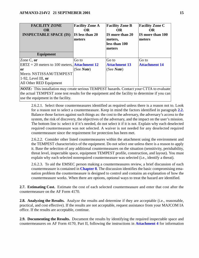
Zone C, orERTZ = 20 meters to 100 meters,orMeets NSTISSAM/TEMPEST1-92, Level III, orAll Other RED Equipment
Go toAttachment 12(See Note)
Go toAttachment 13(See Note)
Go toAttachment 14
NOTE: This installation may create serious TEMPEST hazards. Contact your CTTA to evaluatethe actual TEMPEST zone test results for the equipment and the facility to determine if you canuse the equipment in the facility.
FACILITY ZONEOR
INSPECTABLE SPACE (IS)
Facility Zone A ORIS less than 20 meters
Facility Zone B ORIS more than 20 meters,less than 100 meters
Facility Zone C ORIS more than 100 meters
Equipment
16 AFMAN33-214V2 21 SEPTMEBER 2001
systems. Remember that the form establishes EMSEC requirements. It must clearly state to the user whatis required. It is not an inspection report.
2.10. Completing the Information Systems Countermeasures Review. If the communications sys-tems or cryptographic equipment assessment indicated the need for either a communications systems orcryptographic equipment countermeasures review, make the review before completing the countermea-sures review according to Chapter 5.

AFMAN33-214V2 21 SEPTMEBER 2001 17
Chapter 3
THE COMMUNICATIONS SYSTEMS COUNTERMEASURES REVIEW
3.1. Introduction. When the need for communications systems countermeasures is indicated by thecommunications systems assessment, the communications systems countermeasures review determinesthe required countermeasures. Selection is a function of many variables. Chief among these are the:
3.1.1. Separation distance between RED equipment and radio equipment.
3.1.2. Radiation characteristics of the systems processing classified information.
3.1.3. Radio frequency attenuation offered by the facility containing the systems processing classifiedinformation.
3.2. Installation Requirement. Install equipment that processes classified information according to theinstructions in this chapter. The communications systems installation requirements are separate fromother EMSEC requirements. Meet them even when there are no other EMSEC requirements.
3.3. Transmitting Equipment. Use the guidance in this paragraph except when the equipment isaddressed in paragraph 3.4.
3.3.1. Equipment Separation Requirements. This countermeasure is required. Separation guidancefor fixed transmitters and transceivers (transmitters and receivers contained in one unit) is based onthe TEMPEST characteristics of the RED equipment. Separate RED equipment from transmittersaccording to Table 3.1.
3.3.2. Power Requirements. This countermeasure is required. Do not power RED equipment from thesame electrical circuit as radio frequency transmitters and any ancillary equipment, such as controlheads, connected to radio frequency transmitters. Install a separate power circuit for either the REDequipment or the radio frequency transmitter and any ancillary equipment. The separate power circuitis established at the circuit-breaker panel. It is permissible to power both from the same electrical cir-cuit if either the RED equipment or the radio frequency transmitter and any ancillary equipment areequipped with power line filters.
Table 3.1. Separation Requirements for Transmitters.
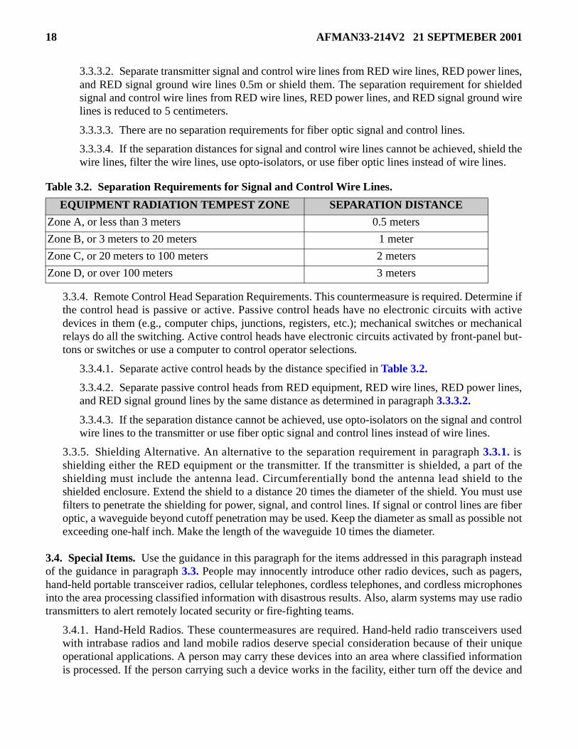
3.3.3. Signal and Control Lines Separation Requirements. This countermeasure is required. These areBLACK lines. If they are wire lines:
3.3.3.1. Separate transmitter signal and control wire lines from RED equipment by the distancespecified in Table 3.2. or shield them. The separation requirement for shielded signal and controlwire lines from RED equipment is reduced to 15 centimeters.
Equipment Radiation TEMPEST Zone SEPARATION DISTANCE
Zone A, or less than 3 meters 2 meters
Zone B, or 3 meters to 20 meters 3 meters
Zone C, or 20 meters to 100 meters 5 meters
Zone D, or over 100 meters 10 meters
18 AFMAN33-214V2 21 SEPTMEBER 2001
3.3.3.2. Separate transmitter signal and control wire lines from RED wire lines, RED power lines,and RED signal ground wire lines 0.5m or shield them. The separation requirement for shieldedsignal and control wire lines from RED wire lines, RED power lines, and RED signal ground wirelines is reduced to 5 centimeters.
3.3.3.3. There are no separation requirements for fiber optic signal and control lines.
3.3.3.4. If the separation distances for signal and control wire lines cannot be achieved, shield thewire lines, filter the wire lines, use opto-isolators, or use fiber optic lines instead of wire lines.
Table 3.2. Separation Requirements for Signal and Control Wire Lines.
3.3.4. Remote Control Head Separation Requirements. This countermeasure is required. Determine ifthe control head is passive or active. Passive control heads have no electronic circuits with activedevices in them (e.g., computer chips, junctions, registers, etc.); mechanical switches or mechanicalrelays do all the switching. Active control heads have electronic circuits activated by front-panel but-tons or switches or use a computer to control operator selections.
3.3.4.1. Separate active control heads by the distance specified in Table 3.2.
3.3.4.2. Separate passive control heads from RED equipment, RED wire lines, RED power lines,and RED signal ground lines by the same distance as determined in paragraph 3.3.3.2.
3.3.4.3. If the separation distance cannot be achieved, use opto-isolators on the signal and controlwire lines to the transmitter or use fiber optic signal and control lines instead of wire lines.
3.3.5. Shielding Alternative. An alternative to the separation requirement in paragraph 3.3.1. isshielding either the RED equipment or the transmitter. If the transmitter is shielded, a part of theshielding must include the antenna lead. Circumferentially bond the antenna lead shield to theshielded enclosure. Extend the shield to a distance 20 times the diameter of the shield. You must usefilters to penetrate the shielding for power, signal, and control lines. If signal or control lines are fiberoptic, a waveguide beyond cutoff penetration may be used. Keep the diameter as small as possible notexceeding one-half inch. Make the length of the waveguide 10 times the diameter.
3.4. Special Items. Use the guidance in this paragraph for the items addressed in this paragraph insteadof the guidance in paragraph 3.3. People may innocently introduce other radio devices, such as pagers,hand-held portable transceiver radios, cellular telephones, cordless telephones, and cordless microphonesinto the area processing classified information with disastrous results. Also, alarm systems may use radiotransmitters to alert remotely located security or fire-fighting teams.
3.4.1. Hand-Held Radios. These countermeasures are required. Hand-held radio transceivers usedwith intrabase radios and land mobile radios deserve special consideration because of their uniqueoperational applications. A person may carry these devices into an area where classified informationis processed. If the person carrying such a device works in the facility, either turn off the device and
EQUIPMENT RADIATION TEMPEST ZONE SEPARATION DISTANCE
Zone A, or less than 3 meters 0.5 meters
Zone B, or 3 meters to 20 meters 1 meter
Zone C, or 20 meters to 100 meters 2 meters
Zone D, or over 100 meters 3 meters

AFMAN33-214V2 21 SEPTMEBER 2001 19
use the telephone or separate it 2 meters from classified processors; no transmissions are allowed. Ifthe person carrying the device is a short-term visitor, it is not necessary to turn off the radio becausethe visitor usually moves about in the facility. Infrequent transmissions are allowed, but only for shortdurations.
3.4.2. Beepers and Pagers. These countermeasures are required. Beepers and pagers deserve specialconsideration because of their unique operational applications. A person may carry these devices intoan area where classified information is processed. If the person carrying such a device works in thefacility, either turn off the device and use the telephone or keep the device 2 meters from classifiedprocessors. If the person carrying the device is a short-term visitor, it is not necessary to turn off thedevice because the visitor usually moves about in the facility. If the device has a transmit capability,follow the instructions for hand-held radios.
3.4.3. Alarm Systems. These countermeasures are required. The mode of operation of alarm systemsradio frequency transmitters will determine their treatment. Any such transmitter with a continuoustransmit mode or a high duty cycle (transmits most of the time) must meet the same separationrequirements as all other fixed transmitters; follow the applicable guidance in paragraph 3.3. If theydo not meet these requirements, exclude them from operating in the classified information processingarea. Low duty cycle (transmits short bursts infrequently) systems are not considered hazards andrequire no special treatment.
3.4.4. Cellular Telephones. These countermeasures are required. When a cellular telephone is used asan operational necessity, separate it 5 meters from RED equipment. When the cellular telephone is apersonal asset, disable the unit from receiving calls or separate it 10 meters from RED processors.Cellular telephones are excluded from operating within 10 meters of the classified information pro-cessing area when the facility is located outside the United States.
3.4.5. Cordless Telephones. These countermeasures are required. When a radio frequency cordlesstelephone is used as an operational necessity, separate it 5 meters from RED equipment. When thecordless telephone is a personal asset, its use is prohibited. Disable the personal cordless telephonefrom receiving calls or separate it 10 meters from RED processors. There are no separation require-ments for infrared cordless telephones. Cordless telephones are excluded from operating within 10meters of the classified information processing area when the facility is located outside the UnitedStates.
3.4.6. Cordless Microphones.
3.4.6.1. Radio Frequency Cordless Microphones. These countermeasures are required. When aradio frequency cordless microphone, encrypted or unencrypted, is used for briefing either classi-fied information or unclassified information, separate it 5 meters from RED equipment. Usingunencrypted radio frequency cordless microphones for classified briefings is prohibited.
3.4.6.2. Infrared Cordless Microphones. These countermeasures are required. Using an infraredcordless microphone for briefing classified information requires blocking the line of sight to apossible place where an adversary could detect the infrared emanations. Do not forget that smoothor shiny surfaces cause infrared signals to be reflected. The best solution is to use a closed room,keeping the doors closed and covering the windows with drapes.
3.4.7. Cordless Accessories. These countermeasures are required. When a radio frequency cordlessaccessory such as a keyboard or a mouse is used, separate it 5 meters from RED equipment. Radio fre-quency cordless accessories cannot be used to process classified information unless encrypted.
20 AFMAN33-214V2 21 SEPTMEBER 2001
3.4.8. Wireless Local Area Networks (LAN). These countermeasures are required. When a radio fre-quency wireless LAN is used, separate the transmitter and receiver units 5 meters from RED equip-ment.
3.4.9. Infrared LANs. These countermeasures are required. An infrared LAN processing classifiedinformation requires blocking the line of sight to a possible place where an adversary could detect theinfrared emanations. Do not forget that smooth or shiny surfaces cause infrared signals to be reflected.The best solution is to use a closed room, keeping the doors closed and covering the windows withdrapes.
3.4.10. Infrared Devices. These countermeasures are required. Infrared devices not covered by anysubparagraph of paragraph 3.4. require blocking the line of sight to a possible place where an adver-sary could detect the infrared emanations. Do not forget that smooth or shiny surfaces cause infraredsignals to be reflected. The best solution is to use a closed room, keeping the doors closed and cover-ing the windows with drapes.
3.5. Estimating Cost. Estimate the cost of each selected countermeasure and enter that cost after thecountermeasure on the AF Form 4170.
3.6. Analyzing the Results. Analyze the results and determine if they are acceptable (i.e., reasonable,practical, and cost effective). If the results are not acceptable, request assistance from your MAJCOM IAoffice. If the results are acceptable, continue.
3.7. Documenting the Results. Document the results that identify the required countermeasures on AFForm 4170, Part II, following the instructions in Attachment 4 for communications systems. Remember,the form establishes EMSEC requirements. It must clearly state to the user what is required. It is not aninspection report.
3.8. Completing the Information Systems Countermeasures Review. If the cryptographic equipmentassessment indicated the need for a cryptographic equipment countermeasures review, make the reviewbefore completing the countermeasures reviews according to Chapter 5.

AFMAN33-214V2 21 SEPTMEBER 2001 21
Chapter 4
THE CRYPTOGRAPHIC EQUIPMENT COUNTERMEASURES REVIEW
4.1. Introduction. When the need for cryptographic equipment countermeasures is indicated by thecryptographic equipment assessment, the cryptographic equipment countermeasures review determinesthe required countermeasures. The possibility of the escape of classified information is a function of manyvariables. Chief among these are the:
4.1.1. Separation distance between RED equipment and cryptographic equipment.
4.1.2. Radiation characteristics of the systems processing classified information.
4.1.3. Type of information processed.
4.2. Installation Requirement. Install cryptographic equipment according to the instructions in thischapter. The cryptographic equipment installation requirements are separate from other EMSEC require-ments. Meet them even when there are no other EMSEC requirements.
4.3. Secure Telephone Unit-III (STU-III), Secure Terminal Equipment (STE), and Like Items. These countermeasures are required for STU-III, STE, and secure data devices (SDD). Do the followingwhen connecting ancillary items such as computers and facsimile (FAX) machines to the secure digitaldata port:
4.3.1. Separate the STU-III, STE, or SDD 1 meter from the RED equipment.
4.3.2. Use the manufacturers’ shielded cable to connect the STU-III, STE, or SDD to the RED equip-ment. If the manufacturers’ shielded cable is not available, use a generic shielded cable.
4.4. Cryptographic System KIV-7. These countermeasures are required for KIV-7 cryptographic sys-tems.
4.4.1. Do the following when the KIV-7 is installed in a computer:
4.4.1.1. Do not use the computer’s internal modem; use an external modem.
4.4.1.2. Separate the external modem 1 meter from the RED equipment.
4.4.1.3. Use the cables (for installing the KIV-7 in a computer) made by the KIV-7 manufacturer.All cables not made by the manufacturer must meet the same requirements as the manufacturer’scables.
4.4.1.4. There are no separation requirements between the KIV-7 and RED or BLACK equip-ment.
4.4.2. Do the following when installing the KIV-7 in a rack near a computer:
4.4.2.1. Do not use the computer’s internal modem; use an external modem.
4.4.2.2. Use the cables (for installing the KIV-7 in a rack near a computer) made by the KIV-7manufacturer. All cables not made by the manufacturer must meet the same requirements as themanufacturer’s cables.

22 AFMAN33-214V2 21 SEPTMEBER 2001
4.4.2.3. A rack is not required if the KIV-7 is not installed in a computer. When installing theKIV-7 in an external rack, use the manufacturer’s supplied rack. If you are not using a rack madeby the manufacturer, your rack must meet the same requirements as the manufacturer’s rack.
4.4.2.4. Separate the modem 1 meter from the RED equipment.
4.4.2.5. There are no separation requirements between the KIV-7 and RED or BLACK equip-ment.
4.4.3. Do the following when the KIV-7 is installed in a stand-alone mode (similar to a cryptographicroom):
4.4.3.1. Do not use the internal modem of an equipment processing classified information unlessthe equipment is TEMPEST certified. Use an external modem.
4.4.3.2. Connect the KIV-7 to BLACK power.
4.4.3.3. Shield both the RED and BLACK wire lines. Connect the shields to the appropriate REDand BLACK signal grounds.
4.4.3.4. A rack is not required if the KIV-7 is not installed in a computer. Whenever possible, usethe manufacturer’s supplied rack. If you are not using a rack made by the manufacturer, your rackmust meet the same requirements as the manufacturer’s rack.
4.4.3.5. There are no separation requirements between the KIV-7 and RED or BLACK equip-ment.
4.5. FORTEZZA For Classified (FFC). These countermeasures are required for FFC cryptographicsystems. Do the following when using a FFC card to secure a computer:
4.5.1. Do not use the internal modem if one is installed in the computer; use an external modem. Theonly exception is the palladium modem card associated with the remote access security program.
4.5.2. Separate the modem 1 meter from the RED equipment.
4.5.3. There are no separation requirements between the FFC card and RED or BLACK equipment.
4.5.4. Separate RED equipment from BLACK equipment according to control of compromising ema-nations requirements.
4.6. Electronic Key Management System (EKMS). The EKMS processes and manages cryptographickey in electronic form. The basic unit consists of a key processor and a computer. Associated with theEKMS is either a STU-III, STE, SDD, or other cryptographic equipment and a data transfer device (DTD)or laptop computer.
4.6.1. Within the basic setup of the EKMS there is no separation requirements. The cables are notlong enough for the standard 1-meter RED and BLACK equipment separation. The basic unit wastested and meets TEMPEST requirements. Testing also included the STU-III, STE, SDD, other cryp-tographic equipment, and a DTD.
4.6.2. External to the basic setup of the EKMS, these countermeasures are required:
4.6.2.1. Connect the EKMS to BLACK power.
4.6.2.2. Separate the EKMS from:

AFMAN33-214V2 21 SEPTMEBER 2001 23
4.6.2.2.1. Other RED equipment and BLACK equipment by 1 meter. Separate the EKMSfrom other TEMPEST-certified equipment by 5 centimeters.
4.6.2.2.2. Power lines by 5 centimeters.
4.6.2.2.3. Other RED and BLACK wire lines by 5 centimeters.
4.7. All Other Cryptographic Equipment. These countermeasures are required. In a facility where allthe equipment on the RED side of the cryptographic equipment is considered RED, the installation of thecryptographic equipment must follow the installation standards in the technical publications related to thecryptographic equipment. If not specified, the following countermeasures are required:
4.7.1. Do not use the computer’s internal modem; use an external modem.
4.7.2. Connect the cryptographic equipment to BLACK power. Shield the BLACK power distribu-tion facility when not costly.
4.7.3. Shield both the RED and BLACK wire lines. Connect the shields to the appropriate RED andBLACK signal grounds. Cryptographic equipment is designed for use with shielded cables. Theshields from these cables are grounded through the connector backshell to the appropriate ground inthe equipment.
4.7.4. RED and BLACK signal grounds are not required except for facilities where the signal groundis not totally contained within the inspectable space. Use RED and BLACK signal grounds if alreadyinstalled and are within 10 meters of the cryptographic equipment.
4.7.5. Separate cryptographic equipment from:
4.7.5.1. RED equipment and BLACK equipment by 1 meter. Separate cryptographic equipmentfrom TEMPEST-certified equipment by 5 centimeters.
4.7.5.2. Power lines by 5 centimeters.
4.7.5.3. RED and BLACK wire lines by 5 centimeters.
4.7.6. Separate the RED and BLACK cables connected to the cryptographic equipment by 5 centime-ters.
4.7.7. Separate RED and BLACK patch panels and connection facilities by 1 meter (e.g., distributionframes).
4.8. Changing From Unclassified to Classified Processing. These countermeasures are required whenit is a fixed facility like weather (generally, weather information is considered unclassified in peace timebut may become classified during war time). The guidance here is not intended for day-to-day use whereclassified information is processed for a short time intermixed with processing unclassified information.In those cases, the equipment is considered RED all the time. If the facility has equipment on the REDside of the cryptographic equipment that does not process classified information now but may processclassified information in the future, follow these special installation procedures for this unique channel.There are two conditions that may exist:
4.8.1. Condition One. If the facility is all BLACK, treat the potentially RED equipment on the REDside of the cryptographic equipment as RED equipment.

24 AFMAN33-214V2 21 SEPTMEBER 2001
4.8.1.1. Isolate the potentially RED equipment in the same way that RED equipment is isolated.That is, no unprotected connections outside the future secure area.
4.8.1.2. Separate the potentially RED equipment from other BLACK equipment as if it were REDequipment.
4.8.1.3. Follow the installation guidance in paragraph 4.5.
4.8.2. Condition Two. If the facility presently contains both RED and BLACK equipment, and theuser cannot properly isolate the potentially RED equipment on the RED side of the cryptographicequipment to meet RED equipment standards (e.g., it is connected to outside BLACK sources), thenseparate it from the RED equipment as well as other BLACK equipment. Follow the guidance in para-graph 4.5., modified as follows:
4.8.2.1. Provide a separate (third) RED distribution facility, RED patch panel, and RED connec-tion facilities (e.g., distribution frames).
4.8.2.2. Shield the RED and BLACK wires associated with this channel.
4.8.2.3. Provide a separate (third) RED signal ground as required.
4.8.2.4. Connect the RED cable shields, RED signal ground on the cryptographic equipment, andthe potential RED equipment associated with this channel to the third RED signal ground.
4.9. Analyzing the Results. Analyze the results and determine if they are acceptable (i.e., reasonable,practical, and cost effective). If the results are not acceptable, request assistance from your MAJCOM IAoffice. If the results are acceptable, continue.
4.10. Documenting the Results. Document the results that identify the required countermeasures on AFForm 4170, Part II, following the instructions in Attachment 4 for cryptographic equipment. Remember,the form establishes EMSEC requirements. It must clearly state to the user what is required. It is not aninspection report.
4.11. Completing the Cryptographic Equipment Countermeasures Review. Complete the counter-measures reviews according to Chapter 5.

AFMAN33-214V2 21 SEPTMEBER 2001 25
Chapter 5
COMPLETING THE COUNTERMEASURES REVIEWS
5.1. Introduction. Completing the EMSEC countermeasures reviews for information systems, commu-nications systems, and cryptographic equipment requires: authenticating and validating the informationsystems, communications systems, and cryptographic equipment countermeasures reviews; applying thecountermeasures; inspecting the system; and certifying EMSEC requirements have been met. All this isdocumented on AF Form 4170. If the countermeasures reviews are made by a person other than the onewho made the EMSEC assessments, use a new AF Form 4170 for the countermeasures reviews. Enter thesame tracking number for this AF Form 4170 for the countermeasures reviews as was used for theEMSEC assessments. Use the same tracking number when the countermeasures reviews are documentedon a different AF Form 4170 than the assessments.
5.2. Classification Marking. If required by another classification guide, re-mark the completed AFForm 4170 with the required classification marking if higher than CONFIDENTIAL. Cross out the clas-sification authority in the upper right-hand block of the form and identify the classification guide. Enterthe declassify date in the upper right hand box which is 10 years (or whatever is specified in the classifi-cation guide requiring a higher level of classification) from the date of the EMSEC assessments in block6C. As a minimum, cross out or mark through the “When Filled In” part of the classification marking atthe top and bottom, front and back, of the form.
5.3. Authentication Documentation. Type or print the name of the IA person, organization, and officesymbol making the EMSEC countermeasures reviews in block 6A. The IA person signs the form in thisblock. Signing by the IA person establishes EMSEC requirements the user must adhere to according toAFI 33-203. When a CTTA makes the EMSEC countermeasures reviews, use “CTTA” as the organizationand office symbol. The CTTA signs the form in this block (see Figure A22.1. for an example.)
5.4. Tracking and Address Information. To avoid unnecessary costs associated with mailing classifieddocuments, CTTA validation will be made by separate, unclassified correspondence; the preferredmedium is electronic mail (E-mail). The IA office completing the AF Form 4170 completes block 7 of theform. Enter the “Tracking Number.” This number has three parts: MAJCOM, base, 3-digit number (e.g.,AFCA-Scott-001). The 3-digit number is unique for each EMSEC assessment and countermeasuresreview on the base. Enter the IA office’s E-mail, message, or mailing address. (See Figure A22.1. for anexample.)
5.5. Validating the Countermeasures Reviews. A CTTA must validate all countermeasures reviews.Forward all countermeasures reviews to HQ AFCA/TCBA-CTTA.
5.5.1. SCI, Special Access Required, and Special Access Programs. Validate all countermeasuresreviews for these categories of information before applying countermeasures; this is a must.
5.5.2. Shielding or TEMPEST-Certified Equipment. Validate all countermeasures reviews that iden-tify using shielding or TEMPEST-certified equipment before implementing any shielding or acquiringTEMPEST-certified equipment; this is a must.

26 AFMAN33-214V2 21 SEPTMEBER 2001
5.5.2.1. Justify all requirements for facility shielding, shielded enclosures, equipment encapsula-tion, or TEMPEST-certified equipment. Base all decisions to use shielding or TEMPEST-certifiedequipment on the results of either a cost analysis or feasibility study.
5.5.2.1.1. The cost analysis must clearly show that using shielding (facility, enclosure, orencapsulation) or TEMPEST-certified equipment is less expensive than applying all requiredcountermeasures identified by the countermeasures review.
5.5.2.1.2. The feasibility study must show that the available inspectable space cannot containthe compromising emanations, the user cannot extend the inspectable space, and there is noother equipment available with an acceptable TEMPEST profile that meets operational or mis-sion requirements.
5.5.2.1.3. Both the cost analysis and the feasibility study must show the chosen option is theless expensive.
5.5.2.2. The IA office sends the countermeasures review, with the justification, to the MAJCOMIA office.
5.5.2.3. If the MAJCOM IA office disagrees with the countermeasures review, return it to the IAoffice for revision.
5.5.2.4. If the MAJCOM IA office agrees with the countermeasures review, indicate concurrenceand send it to HQ AFCA/TCBA-CTTA.
5.5.2.5. If the CTTA disagrees with the countermeasures review, return it through the MAJCOMIA office to the IA office for revision.
5.5.2.6. If the CTTA agrees with the countermeasures review, validate it (see Figure A22.1. foran example of how to enter the CTTA validation), make a copy of the AF Form 4170, file the copyand supporting documentation, and return the original AF Form 4170 through the MAJCOM IAoffice to the IA office.
5.5.3. All Other Countermeasures Reviews. Validation prior to the application of countermeasures isnot required unless the total cost of countermeasures exceeds $1,000.00. If countermeasure costs willexceed $1,000.00, validate all countermeasures reviews before implementing any countermeasures;this is a must.
5.5.3.1. The IA office sends a copy of the countermeasures review to HQ AFCA/TCBA throughor to the MAJCOM IA office if the MAJCOM IA office requires it.
5.5.3.2. If the CTTA disagrees with the countermeasures review, return it to the IA office for revi-sion through or to the MAJCOM IA office if the MAJCOM IA office requires it.
5.5.3.3. If the CTTA agrees with the countermeasures review, validate it and inform the IA office.The CTTA files the countermeasures review and supporting documentation.
5.6. Inform the User. The IA office types or prints the name of the user, organization, office symbol,and telephone number in block 6B (see Figure A22.1.). Explain to the user the required countermeasures.Inform the user of the limitations on moving equipment. For example, if the EMSEC requirements are thesame for anywhere within the building where the equipment is currently installed, then the user may movethe equipment anywhere within the building but must maintain the countermeasures identified on the AFForm 4170. The user signs the form in this block. Signing by the user is acknowledgment that the user has

AFMAN33-214V2 21 SEPTMEBER 2001 27
been informed of EMSEC requirements and understands what is required. Provide the user a memoran-dum identifying the required countermeasures. Use the Tracking Number for identification, do not use theinformation in AF Form 4170, blocks 1 and 2. See Attachment 15 for an example.
5.7. Date. Type or print the date of the EMSEC countermeasures review in block 6C.
5.8. Apply the Countermeasures. The user applies the required countermeasures and notifies the IAoffice.
5.9. Emission Security Inspection. The IA office must make an EMSEC inspection prior to certifica-tion or recertification. The countermeasures reviews are the basis for the EMSEC inspection. The inspec-tion is to make sure all required information systems, communications systems, cryptographic equipment,and IA countermeasures are effectively implemented or applied. The user must correct all deficienciesdiscovered by an EMSEC inspection or request a temporary or permanent waiver. When all deficiencieshave been corrected or the waiver completed, the user requests a re-inspection. The user must maintainthe countermeasures. Document the results of the inspection in a standard memorandum, dated, addressedto the user, and signed by the chief of the IA office. The IA office files a copy with the AF Form 4170.
5.10. Waivers. Attach any waivers to the countermeasures reviews.
5.11. Emission Security Certification. After the EMSEC inspection determines all required EMSECand IA countermeasures are effectively implemented or applied, the system can be EMSEC certified.Type or print the name of the IA person, organization, and office symbol making the EMSEC inspectionin block 9A. The IA person signs the form in block 9B. Enter the date in block 9C. Completing block 9satisfies the EMSEC portion of the system C&A process (see Figure A22.1.). To avoid classifying theC&A package, the IA office issues a memorandum to the user stating EMSEC certification is met. Referto the tracking number and identify the location where the AF Form 4170 is filed in the memorandum. Donot use the information in AF Form 4170, blocks 1 and 2. See Attachment 16 for an example of anEMSEC certification memorandum.
5.12. File Copy. The IA office maintains a copy of the AF Form 4170 on file until the system no longerprocesses classified information. Maintain a copy of the EMSEC requirements memorandum and theEMSEC certification memorandum with the AF Form 4170. Check with the user annually and verify theinformation in blocks 1, 2, and 3 is still valid. When you make and document a new EMSEC countermea-sures review, destroy the previous one. Use the same tracking number.
5.13. Reassessments and Recertifications. Reassessments are made when a system must be recertified(C&A recertifications are required at least every three years), the threat changes, or the classification levelof the classified information changes.
5.13.1. Make the EMSEC countermeasures reviews again (information systems, communicationssystems, or cryptographic equipment, as required).
28 AFMAN33-214V2 21 SEPTMEBER 2001
5.13.1.1. If there are no changes, annotate the original AF Form 4170 with the informationrequired in block 6A (if different, otherwise initial) and the date.
5.13.1.2. If there are significant changes, reaccomplish the AF Form 4170 to reflect the currentrequirements.
5.13.2. Follow the guidance in paragraphs 5.1. through 5.12.

AFMAN33-214V2 21 SEPTMEBER 2001 29
Chapter 6
EMISSION SECURITY MAINTENANCE
6.1. Maintaining Equipment and Countermeasures. Properly maintaining equipment and EMSECcountermeasures is essential.
6.2. Maintenance Requirements. Air Force users:
6.2.1. Ensure equipment used to process classified information is afforded adequate physical protec-tion during maintenance.
6.2.2. Ensure equipment is maintained properly by appropriately cleared and qualified maintainers.
6.2.3. Control the disposition of TEMPEST-certified equipment (see paragraph 6.8.) to prevent tech-nology transfer.
6.2.4. Do not maintain the TEMPEST integrity of TEMPEST-certified equipment when there is noneed.
6.3. Ensuring the Integrity of TEMPEST-Certified Equipment. When TEMPEST-certified equip-ment listed on the Preferred Products List, Endorsed TEMPEST Products List (ETPL), or designed andtested to meet National Security Telecommunications and Information Systems Security Advisory Mem-orandum (NSTISSAM)/TEMPEST 1-92, (C) Compromising Emanations Laboratory Test Requirements,Electromagnetics (U), Level I standards is justified, maintain the TEMPEST integrity. When maintenanceis performed on such equipment no unauthorized component substitutions, modifications, or alterationsare allowed. Maintain the configuration of such equipment to the as-certified condition. When TEM-PEST-certified equipment is justified, the following applies:
6.3.1. Procurement Requirements. In the specifications portion of a contract for TEMPEST-certifiedequipment, include the following items for delivery: a hardware maintenance manual, a maintenanceinstruction course, and a guarantee of the critical spare parts used in the design and manufacture of theequipment to meet NSTISSAM/TEMPEST 1-92, Level I limits. These items are separate line itemson the purchase request submitted to the contracting office. Design these requirements to give the AirForce the most flexibility to achieve the most cost-effective support of the equipment (e.g., the choiceof using the equipment manufacturer, an independent contractor, Air Force, Government ServicesAdministration, etc., to provide qualified maintainers).
6.3.1.1. Hardware Maintenance Manual. Require the contractor to deliver a hardware mainte-nance manual for the product. The manual must contain instructions and maintenance aids neces-sary to support the maintenance of each critical compromising emanation suppression feature ofthe product. Examples of maintenance aids are troubleshooting charts, schematic diagrams, wiringdiagrams, and illustrations. Classify this manual as necessary according to AFMAN 33-272, (S)Classifying Communications Security, TEMPEST, and C4 Systems Security Research and Devel-opment Information (U).
6.3.1.2. Maintenance Course. Require the contractor to deliver a course such that each traineeknows the unique restrictions or precautions necessary to maintain the TEMPEST integrity of theproduct and are provided access to and are instructed in the use of the maintenance manual. Theacquiring agency determines the place, time, and method for instruction.

30 AFMAN33-214V2 21 SEPTMEBER 2001
6.3.1.3. Critical Spare Parts. Require the contractor to guarantee the production and supply ofcritical spare parts for the life of the equipment. Where source suppression techniques are used, itis essential that the contractor guarantee the availability and integrity of those critical spare partswhere the substitution of similar parts may negate the TEMPEST integrity of the product.
6.3.2. Technician Qualifications. To maintain TEMPEST-certified equipment, maintainers must meetcertain requirements.
6.3.2.1. Clearance. Maintainers must have a U.S. SECRET or equivalent clearance to maintainTEMPEST-certified equipment. In instances where TOP SECRET or Special Category (SPECAT)information is processed, consider a higher clearance. If access to classified information isrequired, must receive a favorable National Agency Check (see AFI 31-501, Personnel SecurityProgram Management).
6.3.2.2. Knowledge. Know the specific suppression countermeasures incorporated into the designand manufacture of the particular piece of TEMPEST-certified equipment. Since this knowledgewill come from instruction on maintaining the equipment, document when the instruction isreceived.
6.3.3. Technician Authorization.
6.3.3.1. U.S. military and civil service maintainers are authorized by the base communicationsand information systems officer (CSO), chief of maintenance, or chief of mission systems flight,to maintain TEMPEST-certified equipment when they meet the requirements identified in para-graph 6.3.2.
6.3.3.2. Contractor maintainers are authorized by the contracting officer to maintain TEM-PEST-certified equipment when they meet the requirements identified in paragraph 6.3.2.
6.4. When Not to Maintain the TEMPEST Integrity. There are situations where the use of TEM-PEST-certified equipment is no longer needed to meet control of compromising emanations requirements.This occurs because the TEMPEST-certified equipment was obtained to satisfy control of compromisingemanations requirements based on older, more stringent requirements or a new control of compromisingemanations assessment or countermeasures review determines less control of compromising emanationsis required.
6.4.1. When a user determines that maintaining the TEMPEST integrity of TEMPEST-certifiedequipment is no longer required, the user can achieve significant cost savings. Maintaining the criticalfeatures designed into the TEMPEST-certified equipment is not required. Certain, usually expensive,replaceable parts, such as the drive mechanism for removable hard drives, are not required. Qualifiedmaintainers are not required.
6.4.2. If the use of TEMPEST-certified equipment is no longer justified, take one of two options:
6.4.2.1. Option 1. If possible, use the TEMPEST-certified equipment to satisfy other justifiedrequirements for TEMPEST-certified equipment. In most cases, this procedure is limited toexchanging or transferring equipment to users on the same installation.
6.4.2.2. Option 2. Stop maintaining the TEMPEST integrity of the equipment.
6.4.3. Decertify the equipment as TEMPEST certified once the equipment is repaired by eitherreplacing a critical part with a non-TEMPEST part or when a maintainer not authorized to maintain

AFMAN33-214V2 21 SEPTMEBER 2001 31
TEMPEST-certified equipment performs maintenance. The CSO authorizes the decertification ofTEMPEST-certified equipment on a case-by-case basis.
6.4.4. When the equipment is decertified, the equipment and the equipment records must clearly indi-cate that this equipment is no longer TEMPEST certified as of that date.
NOTE: One method for marking the equipment is to attach a label near the automated data processingequipment identification label and an entry in the equipment record that says: EQUIPMENT NOLONGER TEMPEST CERTIFIED. DATE: ______, followed by the name of the decertifying official,signature, organization, and office symbol.
6.5. Transportation of Equipment for Maintenance. When classified information processing equip-ment is removed from its operating location for maintenance or repair purposes, ensure compliance withthe safeguarding and transportation requirements of DoD 5200.1-R. Additionally:
6.5.1. Purge the equipment of all stored classified information, whenever possible, before removingthe equipment from its operating location. See AFSSI 5020, Remanence Security (will becomeAFMAN 33-224). If the user cannot purge the equipment, treat the equipment as a classified item dur-ing transportation and repair.
6.5.2. Maintain a record of the day and time of the removal of the item from its operating location, itsarrival at the repair facility, when the item is picked up from the repair facility, and when it is returnedto its operating location. Keep the record for one year.
6.6. Repair Facilities. Repair facilities are accredited to the highest level of classified informationstored within them.
6.7. Emission Security Documentation-of-Maintenance Requirements. Maintain a log that identifiesthe equipment, the serial number of the equipment, the day and time of arrival at the repair facility, whenrepair was started, the person making the repair, when the repair was completed, and when the equipmentwas released from the repair facility.
6.8. Disposing of TEMPEST-Certified Equipment.
6.8.1. Protect the suppression technology used in TEMPEST-certified equipment and formerly TEM-PEST-certified equipment from general distribution to prevent technology transfer by controlling itsdisposition.
6.8.2. Ensure disposition or resale is consistent with established export control and technology trans-fer requirements. Since these requirements are subject to change, direct questions to your MAJCOMIA office or HQ AFCA/TCBA-CTTA.
32 AFMAN33-214V2 21 SEPTMEBER 2001
Chapter 7
EMISSION SECURITY TESTING
7.1. Purpose of Testing. The purpose of EMSEC testing is to:
7.1.1. Discover EMSEC Hazards. To process classified information safely, eliminate EMSEC haz-ards. Testing determines the extent and nature of compromising emanations.
7.1.2. Identify Equipment Vulnerabilities. Identifying the specific vulnerabilities of equipment allowsfor an informed selection of the best method of protection such as equipment modifications, installa-tion changes, additional countermeasures, changes in operating procedures, or increasing physicalsecurity.
7.1.3. Determine Safe Limits for Facilities. Knowing the safe limits of a facility permits the EMSECmanager to select only the countermeasures needed.
7.2. Kinds of Emission Security Tests. There are four kinds of EMSEC tests:
7.2.1. Facility Tests. Facility tests are conducted to determine if compromising emanations are detect-able beyond the inspectable space for a facility. These tests determine the profile of a facility and theresults are valid so long as no changes are made in the physical arrangements of the facility or theequipment in the facility.
7.2.2. Zone Tests. Zone tests are conducted in two parts. One part tests a facility to determine theamount of free space attenuation (zone) offered by the facility. The other part tests the equipment in alaboratory environment to determine the range (zone) of compromising emanations from the equip-ment.
7.2.3. Aircraft Tests. Aircraft are tested primarily for communications systems and cryptographicequipment.
7.2.4. Laboratory Tests. Laboratory (shielded enclosure) tests determine the exact nature of all com-promising emanations produced by equipment. Results of laboratory tests are generally applied to allapplications of the equipment without regard to the specific facility.
7.3. When to Test.
7.3.1. Request a test when one of the following conditions exists:
7.3.1.1. A technical intercept action against the facility is probable.
7.3.1.2. When classified information is processed on aircraft. All specialized aircraft configura-tions are tested. Other aircraft are tested randomly when requested by HQ USAF or a MAJCOM.
7.3.2. Consider requesting a test when one of the following conditions exists where EMSEC isrequired:
7.3.2.1. A significant difference between the equipment’s published TEMPEST zone or TEM-PEST profile and the facility zone or inspectable space.
7.3.2.2. If the installation is new.

AFMAN33-214V2 21 SEPTMEBER 2001 33
7.3.2.3. The equipment does not meet the established EMSEC installation requirements for thefacility because of space limitations, environmental, or operational use (such as mobile vans andaircraft). This condition applies only when processing TOP SECRET information in the UnitedStates, and when SECRET or higher information is processed outside the United States.
7.3.2.4. Sufficient TEMPEST profile data on the equipment is not available and TOP SECRETinformation is processed in a facility within the United States, or SECRET or higher informationis processed outside the United States.
7.3.2.5. When using the zoning method to contain compromising emanations within the inspect-able space.
7.3.3. Classify the condition listed in paragraph 7.3.1.1. SECRET when used as justification. Classifythe conditions listed in paragraphs 7.3.2.1. or 7.3.2.3. CONFIDENTIAL when used as justification fora test request.
7.4. Requesting a Test. The wing IA office and the user consult on the need for a test. If a test is needed,the wing IA office prepares the request and the user provides the wing IA office the necessary information(see Attachment 17). If the user desires a test, the user prepares the request and forwards it to the wing IAoffice. The wing IA office forwards the request through the MAJCOM IA office or SPECAT EMSECmanager to HQ AFCA/TCBA-CTTA.
7.5. Emission Security Test Results. The results of an EMSEC test take precedence over all other guid-ance. Correct hazards or complete a temporary or permanent waiver (see AFI 33-203) before processingclassified information.

34 AFMAN33-214V2 21 SEPTMEBER 2001
Chapter 8
EMISSION SECURITY COUNTERMEASURES
8.1. Introduction. The various EMSEC countermeasures used to prevent or reduce the opportunity foran adversary to detect compromising emanations and gain intelligence information are discussed in thischapter. The countermeasures for communications systems and cryptographic equipment are alsoincluded since they are essentially the same. Here, for each countermeasure, an attempt is made to explainwhat the vulnerability is, what the countermeasure is for that vulnerability, what the countermeasure does,the reasons or conditions that would negate the need for the countermeasure, some information on how toapply the countermeasure, and alternatives to the countermeasure.
8.2. Fundamentals of Compromising Emanations. Selecting and applying countermeasures are deter-mined by the EMSEC countermeasures review and the selection will vary depending on the amount ofinspectable space, the EMSEC characteristics of the equipment used to process classified information,separation distances, and the level of physical security. One of the more difficult things to do in EMSECis to select countermeasures. For the control of compromising emanations, Attachment 6 throughAttachment 14 contain listings of countermeasures to review, dependent on the environment where clas-sified information is processed. In the case of required countermeasures, the person making the counter-measures review is asked to look for a reason not to apply a required countermeasure. In the case ofcountermeasures to consider applying, the person making the countermeasures review is asked to deter-mine when a nonrequired countermeasure is needed and the reason why it is needed. Therefore, in orderto make these decisions, the person making the control of compromising emanations countermeasuresreview needs to know something about electronics, electromagnetic (radio) waves, antennas, and howcompromising emanations are generated.
8.2.1. Circuit Theory. An understanding of where compromising emanations come from involves asimple understanding of basic circuit theory. In basic circuit theory, there is a source, a path, and aload. Basic circuit theory can be seen in simple terms as a battery (source), a pair of wires (path), anda light bulb (load). When properly connected together, current flows from the battery, through onewire to the light bulb, through the light bulb (which does what we want, gives off light), and returns tothe battery by the second wire. If we disconnect the battery, break one of the wires, or remove the lightbulb, current ceases to flow and there is no “signal.” This basic function of current flow in a circuit isused in all electronic equipment.
8.2.2. Integrated Circuits. Nearly all electronic equipment today uses integrated circuits. The ampli-fier is the basic component of the integrated circuit. The amplifier consists of a junction and variousresistances to make the junction perform as desired. When an energy source is applied across the junc-tion, the amplifier is turned on and off by an input signal. The output, since this is an amplifier, is alarger version of the input signal. Adjustments are made to the circuit design to change its amplifica-tion to make it do different things.
8.2.3. Circuit Energy. Every circuit uses more energy than is needed to process the intended signal.There are several reasons for this.
8.2.3.1. When current flows through a circuit, the electrons making up the current flow meet“resistance” and they run into protons, neutrons, etc. Overcoming this “resistance” takes extra
AFMAN33-214V2 21 SEPTMEBER 2001 35
energy, some of which is given off as heat. Most of the extra energy is radiated from the circuit andis known as “noise”; random pieces of energy of different magnitudes, duration, and frequency.
8.2.3.2. The main source of compromising emanations is a result of nature. If you look closely atthe natural world around you, you will not find straight lines. Nature does not support straightlines; it likes rounded things and it likes curves. Sound is curves; scientifically called “sinewaves”. Sunlight is curves; more sine waves but a lot higher in frequency than sound. These sinewaves can be represented easily by mathematical formulas.
8.2.3.3. Humans, however, attempt to defy nature and make computers that use square wavesknown as “digital signals”. These do not occur in nature. They cannot be represented by a mathe-matical formula. When the digital signal goes from one level to another, there is a discontinuity.Mathematically, the digital signal could be presented by one formula like x = 0 for one level andanother formula like x = 5 for the other; however, there is no one formula that represents both lev-els and the jump between levels; hence the discontinuity. Sometimes, scientists mathematicallyrepresent square waves by some fundamental sine wave formula plus all the odd harmonics toinfinity. This formula is hard to use since it would take forever to make a calculation. Practicallyspeaking, engineers and mathematicians use only a few of the first harmonics to design equip-ment.
8.2.3.4. So, when a digital computer is made to change state, that is, go from one level to another,it takes more energy to do that to overcome the resistance and the discontinuity. That extra energydoes not go into the intended signal itself but it has to go somewhere. Some of it is given off asheat. Some of it is given off in random bursts. However, most of it is radiated from the cir-cuit--called “noise”. This noise is organized. Since it only occurs when there is a transitionbetween levels, it can be related to the intended signal. When related, it is called a “compromisingemanation”. When this energy is radiated from the circuit, it looks and acts just like a radio signal.
8.2.3.5. There are a number of things that affect the magnitude of the radiated compromisingemanations. One of the two prime things is the difference in the two levels. The greater the differ-ence, the more energy it takes to make the jump and the bigger the emanation. The other primething is the time it takes to get from one level to the other. The shorter the time, the more energy ittakes to get there and the bigger the compromising emanation. Because of these two factors, com-promising emanations are two, ten, a hundred, sometimes a thousand times greater than theintended signal. Additionally, there are a number of other things that affect not only the magnitudebut even if they will occur; these are impurities in the circuit, temperature, humidity, etc.
8.2.4. Circuit Wiring. This is another source of compromising emanations but appears in a differentform than those caused by the basic circuit. In a wire, when a current is caused to flow through it, amagnetic field is generated around the wire. This property is used in generators to change motionenergy (for instance, falling water) into electricity and is used in motors to change electricity intomotion. This property is not a problem as long as the current stays steady; the magnetic field builds upand remains constant. When the current is made to vary, then the magnetic field changes as the currentchanges When the wire is the right length, it acts like an antenna and radiates an electromagneticfield.. Since the magnetic field is varying as the intended signal is varying, it is easy to relate the twoand this becomes a compromising emanation. The compromising emanations radiated from a wire arenot as strong as the compromising emanations radiated from the circuit so they won’t go as far butthey are more constant; that is, they are always there and at the same relative strength.
36 AFMAN33-214V2 21 SEPTMEBER 2001
8.3. Requirement -- Contain Compromising Emanations. When it is required to control compromis-ing emanations, contain them within the inspectable space. Compromising emanations are classed aseither radiated or conducted based on the escape medium.
8.4. Containing Radiated Compromising Emanations. There are a number of ways available to con-tain radiated compromising emanations within the inspectable space. Base the decision on which methodto use on cost and practicality.
8.4.1. Profile Matching. Match the emission profile of the equipment to the inspectable space. This isthe most direct way to meet the requirement to contain compromising emanations within the inspect-able space. Unfortunately, an EMSEC test is required to establish a profile, the ERTZ. This can becostly and is not timely. Contain the ERTZ within the inspectable space by either expanding theinspectable space or selecting equipment with smaller ERTZs.
8.4.2. Zoning. This method requires two different tests; the facility and the equipment. Once the facil-ity and the equipment are zoned, match zone ratings. Zone testing will: quantify the facility’s attenua-tion characteristics and assign a zone rating; and measure the magnitude of the compromisingemanations from the equipment and assign a zone rating. The cost to zone a facility is based on thetemporary duty costs for a team of three; travel time plus 1 to 1-1/2 days per building. The cost to zonetest equipment is mostly in the cost of shipping the equipment to the test laboratory. It takes 1-to-2days to zone test a PC.
8.4.3. Facility Testing. Testing the facility is one of the best ways to ensure compromising emanationsare contained within the inspectable space. However, this method is costly. The costs depend on thenumber of equipment items tested, which affects the length of stay of the test team. The Air ForceCTTA determines if a request for a facility test will be tasked to the EMSEC test team.
8.4.4. TEMPEST-Certified Equipment. Using TEMPEST-certified equipment is a very good way toensure compromising emanations are contained within the inspectable space. The cost of TEM-PEST-certified equipment is usually 2-to-5 times the cost of off-the-shelf, non-TEMPEST-certifiedequipment. Because this method is very expensive, its use must be justified according to paragraph5.5.2. and validated by a CTTA. TEMPEST-certified equipment is applied mainly in hostile environ-ments where it is known an adversary exploits compromising emanations. Sometimes it is necessaryto employ TEMPEST-certified equipment in other environments considered less hostile but whereU.S. Government control is extremely limited.
8.4.5. Shielding. Shielding the equipment, room, or facility is an excellent way to contain compro-mising emanations within the inspectable space. Because this method is very expensive, its use mustbe justified according to paragraph 5.5.2. and validated by a CTTA. Consider shielding in hostile envi-ronments where it is known compromising emanations are exploited. Also, consider using shieldingin other, less hostile environments where U.S. Government control is extremely limited. Shielding isapplied directly to equipment (encapsulation), rooms (shielded enclosure), or facilities (global). Thereare two standards for shielding effectiveness: (1) The Air Force standard for shielding effectiveness(attenuation) for shielded enclosures and global shielding is 50 dB (plus an initial 10-dB allowance forlife-time degradation). Do not install cryptographic equipment or radio equipment in a shielded enclo-sure. (2) The standard for equipment is NSTISSAM/TEMPEST 1-92, Level I.
8.5. Containing Conducted Compromising Emanations. Evaluating all conductive paths for theescape of compromising emanations is a difficult task because there are so many. The evaluator knows to

AFMAN33-214V2 21 SEPTMEBER 2001 37
look for the obvious paths like telephone lines and other signal lines. Additional, less obvious, paths arethe power lines (and the electrical metallic tubing [emt] they run in), extension cords, signal ground wires,alarm signal lines, fire suppression piping, air conditioning and heating ducts, water pipes, buildingmetallic members, etc. Treat each as specified in the applicable countermeasures review attachment,depending on a number of factors like the threat level, sensitivity of the information, location of the facil-ity on the base relative to the boundary of the inspectable space, etc.
8.6. RED and BLACK Concept. The RED and BLACK concept, by definition, establishes areas forthe placement of equipment processing classified information (RED) that are separate and unique fromthe areas for equipment processing unclassified information (BLACK). The concept has two parts:
8.6.1. Physical Separation. All equipment, wire lines, components, and systems that process classi-fied information are considered RED. All equipment, wire lines, components, and systems that pro-cess encrypted classified information or unclassified information are considered BLACK. The REDand BLACK concept is to establish minimum guidance for physical separation to decrease the proba-bility that electromagnetic emissions from RED devices will couple to BLACK systems.
8.6.2. Electrical Separation. Electrical separation ensures that every signal conductor from a REDdevice is routed to another RED device, or is encrypted before connection to a BLACK device. Elec-trical separation addresses signal distribution, power distribution, and grounding. Switches and otherdevices used to interface between RED and BLACK circuits and equipment should exhibit the follow-ing port-to-port isolation characteristics:
8.6.2.1. 100 dB over the baseband audio frequency range between 0.3 and 15 kilohertz.
8.6.2.2. 80 dB over the baseband video frequency range of 0-to-5 megahertz (MHz).
8.6.2.3. 60 dB over the frequency range from 1 times the basic data rate to 10 times the basic datarate of the digital signals processed.
8.7. RED and BLACK Equipment. RED equipment processes clear-text, classified information.BLACK equipment processes encrypted or unclassified information. Designating equipment as RED orBLACK further ensures the physical and electrical separation requirement. Every RED equipment is con-nected only to another RED equipment or the output is encrypted prior to connection to a BLACK equip-ment. Equipment is comprised of machines which process information in electronic, electrical, orelectromechanical form. As information is processed, current flows in wires and traces in the equipment,electronic circuits change state, switches open and close, solenoids are energized and de-energized,images are created on screens with electron streams, and many other similar actions occur. When theseactions take place, emanations, as discussed in paragraph 8.2., are generated. Normally, these emanationsare seen as noise and are a nuisance that is tolerated or reduced to a tolerable level. These emanations passthrough the atmosphere just like radio and television (TV) broadcast signals, and someone can detect andanalyze them to reveal the information being processed. If classified information is processed, then theseare compromising emanations.
8.8. Countermeasure -- RED Equipment and BLACK Equipment Separation.
8.8.1. What the Problem Is. Compromising emanations are produced in RED equipment as a result ofstate changes in electronic circuits and current flow in traces and wires. The wires, traces, frame, andcover of BLACK equipment can act as receiving antennas and pick up compromising emanations

38 AFMAN33-214V2 21 SEPTMEBER 2001
radiated from nearby RED equipment. The problem is if compromising emanations are picked up byBLACK equipment, they can escape on BLACK wire lines connected to the BLACK equipment andon the BLACK power cord connected to the BLACK equipment.
8.8.2. What the Countermeasure Is. The countermeasure is to separate RED equipment from BLACKequipment.
8.8.3. What the Countermeasure Does. Separation decreases the probability of BLACK equipmentpicking up compromising emanations from RED equipment and escaping the inspectable space onBLACK wire lines connected to BLACK equipment and BLACK power lines.
8.8.4. When the Countermeasure Is Not Needed. This countermeasure is not needed if the means ofescape, that is, BLACK wire lines and BLACK power lines, are controlled. Normally, this counter-measure is not needed if:
8.8.4.1. The line distance of BLACK wire lines connected to BLACK equipment from the build-ing containing the RED equipment to the boundary of the inspectable space is greater than 1,000meters or the BLACK lines are fiber optic, or,
8.8.4.2. A BLACK line isolation countermeasure is used, and,
8.8.4.3. BLACK power lines are contained within the inspectable space up to a point where theaverage load exceeds 100,000 volt-amperes and at least 10,000 volts potential.
8.8.5. How To Apply the Countermeasure. Move the RED equipment away from the BLACK equip-ment by the distance specified in the applicable countermeasures review attachment. Traditionally,under ideal conditions, areas were established in a facility for the placement of RED equipment sepa-rate and unique from areas with BLACK equipment. When this was done, two areas were created: aRED equipment area and a BLACK equipment area. A RED equipment area is the space within a con-trolled access area (CAA) where RED information processing equipment and associated power, sig-nal, control, ground, and signal distribution facilities are installed. A BLACK equipment area is anarea in a CAA area where equipment processing unclassified information or encrypted classifiedinformation and associated power, signal, control, ground, and distribution facilities are installed.However, today, most classified information is processed in an office environment. Often, this envi-ronment does not lend itself to establishing RED equipment areas and BLACK equipment areas eas-ily. However, achieving and maintaining the separation of RED and BLACK equipment may berequired. If an EMSEC test determines that a hazard exists, a countermeasure to consider is to increasethe physical separation distance. A further problem is offices are rearranged from time to time that canlead to a natural laxness where the separation requirements are forgotten.
8.8.6. Alternatives. The alternatives to fully separating RED equipment from BLACK equipment, asrequired in the applicable countermeasures review attachment, are:
8.8.6.1. Use a BLACK wire line isolation countermeasure. This reduces the separation distance to15 percent of the required distance (minimum 15 centimeters), or,
8.8.6.2. Specially orienting RED equipment to BLACK equipment. This alternative requires ori-enting the RED equipment so the internal wiring and traces are not parallel to the BLACK equip-ment internal wiring and traces. Most internal wiring and circuit boards (and by extension, thetraces) may act as antennas. These wires and traces usually run parallel to the edges of the equip-ment. First determine the orientation of the longest runs; up-and-down, side-to-side, orfront-to-back, on both the RED equipment and the BLACK equipment. If the traces are not in the

AFMAN33-214V2 21 SEPTMEBER 2001 39
same plane (one is up-and-down, the other is side-to-side), then, the separation distance is reducedby 50 percent (minimum 15 centimeters). If the traces are parallel, then, orient the RED equipmentat a 45-degree angle to BLACK equipment. The separation distance is reduced by 50 percent(minimum 15 centimeters) with such orientation, or,
8.8.6.3. Use TEMPEST-certified equipment. This reduces the separation distance to 5 centime-ters, or,
8.8.6.4. Shield the equipment to reduce compromising emanations by using the encapsulationtechnique. This reduces the separation distance to 5 percent of the required distance (minimum 5centimeters). If there are several items of RED equipment that need separation from several itemsof BLACK equipment, an alternative to consider is using a shielded enclosure.
8.9. Countermeasure -- RED Equipment and BLACK Wire Line Separation.
8.9.1. What the Problem Is. Compromising emanations are produced in RED equipment as a result ofstate changes in electronic circuits and current flow in traces and wires. The problem is BLACK wirelines can act as receiving antennas and pick up compromising emanations radiated from nearby REDequipment.
8.9.2. What the Countermeasure Is. The countermeasure is to separate RED equipment from BLACKwire lines.
8.9.3. What the Countermeasure Does. Separation decreases the probability of BLACK wire linespicking up compromising emanations from RED equipment and escaping the inspectable space on theBLACK wire lines.
8.9.4. When the Countermeasure Is Not Needed. This countermeasure is not needed if the means ofescape, that is, BLACK wire lines, are controlled. Normally, this countermeasure is not needed if theline distance of the BLACK wire lines from the building containing the RED equipment to the bound-ary of the inspectable space is greater than 2,000 meters or if the BLACK lines are fiber optic.
8.9.5. How To Apply the Countermeasure. Move the RED equipment away from the BLACK wirelines by the distance specified in the applicable countermeasures review attachment.
8.9.6. Alternatives. The alternatives to fully separating RED equipment from BLACK wire lines, asrequired in the applicable countermeasures review attachment, are:
8.9.6.1. Use a BLACK wire line isolation countermeasure. This reduces the separation distance to15 percent of the required distance (minimum 15 centimeters), or,
8.9.6.2. Shield the BLACK wire lines. This reduces the separation distance to 5 percent of therequired distance (minimum 5 centimeters), or,
8.9.6.3. Use TEMPEST-certified equipment. This reduces the separation distance to 5 centime-ters, or,
8.9.6.4. Shield the equipment to reduce compromising emanations by using the encapsulationtechnique. This reduces the separation distance to 5 percent of the required distance (minimum 5centimeters). If there are several RED equipment that need separation from several BLACKequipment, a shielded enclosure will meet the separation requirement.
40 AFMAN33-214V2 21 SEPTMEBER 2001
8.10. Countermeasure -- RED Equipment and BLACK Power Line Separation.
8.10.1. What the Problem Is. Compromising emanations are produced in RED equipment as a resultof state changes in electronic circuits and current flow in traces and wires. The problem is BLACKpower lines can act as receiving antennas and pick up compromising emanations radiated from nearbyRED equipment.
8.10.2. What the Countermeasure Is. The countermeasure is to separate RED equipment fromBLACK power lines.
8.10.3. What the Countermeasure Does. Separation decreases the probability of BLACK power linespicking up compromising emanations from RED equipment and escaping the inspectable space on theBLACK power lines.
8.10.4. When the Countermeasure Is Not Needed. This countermeasure is not needed if the means ofescape, that is, BLACK power lines and BLACK wire lines, are controlled. Normally, this counter-measure is not needed if:
8.10.4.1. BLACK power lines are contained within the inspectable space up to a point where theaverage load exceeds 100,000 volt-amperes and at least 10,000 volts potential, and,
8.10.4.2. The line distance of BLACK wire lines connected to BLACK equipment from the build-ing containing the RED equipment to the boundary of the inspectable space is greater than 1,000meters or the BLACK lines are fiber optic.
8.10.5. How To Apply the Countermeasure. Move the RED equipment away from the BLACK powerlines by the distance specified in the applicable countermeasures review attachment.
8.10.6. Alternatives. The alternatives to fully separating RED equipment from BLACK power lines,as required in the applicable countermeasures review attachment, are:
8.10.6.1. Shield the BLACK power lines. This reduces the separation distance to 5 percent of therequired distance (minimum 5 centimeters), or,
8.10.6.2. Use TEMPEST-certified equipment. This reduces the separation distance to 5 centime-ters, or,
8.10.6.3. Shield the equipment to reduce compromising emanations by using the encapsulationtechnique. This reduces the separation distance to 5 percent of the required distance (minimum 5centimeters). If there are several RED equipment that need separation from several BLACKequipment, a shielded enclosure will meet the separation requirement, or,
8.10.6.4. Filter the BLACK power lines. This reduces the separation distance to 5 percent of therequired distance (minimum 5 centimeters).
8.11. Countermeasure -- RED Equipment and BLACK Signal Ground Wire Separation.
8.11.1. What the Problem Is. Compromising emanations are produced in RED equipment as a resultof state changes in electronic circuits and current flow in traces and wires. BLACK signal groundwires can act as receiving antennas and pick up compromising emanations from nearby RED equip-ment. The problem is BLACK signal ground wires can pick up compromising emanations. They canescape in three ways:

AFMAN33-214V2 21 SEPTMEBER 2001 41
8.11.1.1. Conducting them to the shields on BLACK wire lines where they can be conducted toBLACK equipment and escape the inspectable space on the BLACK wire lines and BLACKpower lines.
8.11.1.2. Conducting them to the shields on BLACK wire lines where they can be impressed onthe BLACK wire lines and escape the inspectable space on the BLACK wire lines.
8.11.1.3. Conducting them back through the filters on BLACK wire lines where they can beimpressed on the BLACK wire lines and escape the inspectable space on the BLACK wire lines.
8.11.2. What the Countermeasure Is. The countermeasure is to separate RED equipment fromBLACK signal ground wires.
8.11.3. What the Countermeasure Does. Separation decreases the probability of BLACK signalground wires picking up compromising emanations from RED equipment and escaping the inspect-able space on BLACK wire lines and BLACK power lines.
8.11.4. When the Countermeasure Is Not Needed. This countermeasure is not needed if the means ofescape, that is, BLACK wire lines, are controlled. Normally, this countermeasure is not needed if theline distance of the BLACK wire lines from the building containing the RED equipment to the bound-ary of the inspectable space is greater than 1,000 meters or the BLACK lines are fiber optic.
8.11.5. How To Apply the Countermeasure. Move the RED equipment away from the BLACK signalground wires by the distance specified in the applicable countermeasures review attachment.
8.11.6. Alternatives. The alternatives to fully separating RED equipment from BLACK signal groundwires, as required in the applicable countermeasures review attachment, are:
8.11.6.1. Use a BLACK wire line isolation countermeasure, and,
8.11.6.2. Filter the BLACK power lines, or,
8.11.6.3. Use TEMPEST-certified equipment. This reduces the separation distance to 5 centime-ters, or,
8.11.6.4. Shield the equipment to reduce compromising emanations by using the encapsulationtechnique. If there are several RED equipment that need separation from several BLACK equip-ment, a shielded enclosure will meet the separation requirement.
8.12. Countermeasure -- RED Equipment and Fortuitous Conductor Separation.
8.12.1. What the Problem Is. Compromising emanations are produced in RED equipment as a resultof state changes in electronic circuits and current flow in traces and wires. Fortuitous conductors canact as receiving antennas and pick up compromising emanations radiated from nearby RED equip-ment. The problem is fortuitous conductors can leave the inspectable space allowing compromisingemanations to escape control. An additional problem is, since fortuitous conductors can run parallel toBLACK wire lines and BLACK power lines, compromising emanations can be coupled to them andescape if the BLACK wire lines or BLACK power lines leave the inspectable space.
8.12.2. What the Countermeasure Is. The countermeasure is to separate RED equipment from fortu-itous conductors.

42 AFMAN33-214V2 21 SEPTMEBER 2001
8.12.3. What the Countermeasure Does. Separation decreases the probability of fortuitous conductorspicking up compromising emanations from RED equipment and escaping the inspectable space on thefortuitous conductors, BLACK wire lines, or BLACK power lines.
8.12.4. When the Countermeasure Is Not Needed. This countermeasure is not needed if the means ofescape, that is, fortuitous conductors, BLACK wire lines, and BLACK power lines, are controlled.Normally, this countermeasure is not needed if fortuitous conductors are contained within the inspect-able space, and:
8.12.4.1. The line distance of the BLACK wire lines from the building containing the RED equip-ment to the boundary of the inspectable space is greater than 250 meters or the BLACK lines arefiber optic, and,
8.12.4.2. The BLACK power lines are contained within the inspectable space up to a point wherethe average load exceeds 100,000 volt-amperes and at least 10,000 volts potential.
8.12.5. How To Apply the Countermeasure. Move the RED equipment away from the fortuitous con-ductors by the distance specified in the applicable countermeasures review attachment.
8.12.6. Alternatives. The alternatives to fully separating RED equipment from fortuitous conductors,as required in the applicable countermeasures review attachment, are:
8.12.6.1. Install nonconductive breaks in all fortuitous conductors at the boundary of the inspect-able space, and,
8.12.6.2. Separate the BLACK wire lines from BLACK power lines by the distance specified inthe applicable countermeasures review attachment, or,
8.12.6.3. Shield the BLACK wire lines and BLACK power lines. This reduces the separation dis-tance to 5 percent of the required distance (minimum 5 centimeters), or,
8.12.6.4. Use TEMPEST-certified equipment. This reduces the separation distance to 5 centime-ters, or,
8.12.6.5. Shield the equipment to reduce compromising emanations by encapsulation. If there isRED equipment that needs separation from BLACK equipment, a shielded enclosure will meet theseparation requirement.
8.13. Countermeasure -- Low-Level Signaling.
8.13.1. What the Problem Is. Compromising emanations are produced in RED equipment as a resultof state changes in electronic circuits, current flow in traces and wires, switches opening and closing,energizing and de-energizing solenoids, creating images on screens with electron streams, and manyother similar actions. The problem is the stronger the emanations, the more hazards there are.
8.13.2. What the Countermeasure Is. The requirement is to use low-level signaling within andbetween equipment.
8.13.3. What the Countermeasure Does. This requirement reduces the strength of compromisingemanations. The separation requirements established in this memorandum are based on low-level sig-naling.
AFMAN33-214V2 21 SEPTMEBER 2001 43
8.13.4. When the Countermeasure Is Not Needed. This countermeasure is not needed when there isover 10,000 meters of inspectable space, all wires are shielded, and RED equipment is separated fromBLACK equipment 10 times the required distance. CTTA assistance is a must in this situation.
8.13.5. How To Apply the Countermeasure. A low-level signal is a current-driven signal, plus orminus 2 volts at 70 microamperes, or a voltage-driven signal, plus or minus 6 volts.
8.13.6. Alternative. This requirement is not needed when the equipment is installed in a shieldedenclosure or when there is over 10,000 meters of inspectable space, all wires are shielded, and REDequipment is separated from BLACK equipment ten times the required distance.
8.14. Signal Lines. There are two kinds of signal lines, wire and fiber optic. Signal wire lines are metal-lic wires that carry an electrical signal from one piece of equipment to another. Fiber optic lines that carrysignals also are called “signal lines” but not “signal wire lines”. Signal wire lines are also known as cablesor conductors. Signal wire lines vary according to equipment design. A mix of single wires, twisted pair,coaxial, and ribbon is typically found. Twisted pair cable is predominant between large systems andwithin facilities. Signal wire lines, which carry current, generate an electromagnetic field around the wirethat produces an electromagnetic wave; in other words, the signal wire line acts as a transmitting antenna.The magnitude of this field is directly related to the magnitude of the signal and varies as the signal varies.Additionally, in the case of digital signals, the transitions from mark-to-space and space-to-mark (orone-to-zero and zero-to-one or high-to-low and low-to-high) can produce radiated electromagnetic spikesmuch larger than the original magnitude of the signal-state change. If processing classified information,then these are compromising emanations and may require EMSEC countermeasures.
8.15. RED and BLACK Wire Lines. RED wire lines carry clear-text, classified, and classified infor-mation. BLACK wire lines carry unclassified information or encrypted classified information. Designat-ing signal lines as RED or BLACK further ensures the physical and electrical separation requirement.Every signal conductor from a RED device is routed only to another RED device or is encrypted prior toconnecting to a BLACK device.
8.16. Countermeasure -- RED Wire Line and BLACK Equipment Separation.
8.16.1. What the Problem Is. Compromising emanations are produced around RED wire lines as aresult of current flow in the wire generating a magnetic field that produces an electromagnetic wave;in other words, the RED wire line acts as a transmitting antenna. The wires, traces, frame, and coversof BLACK equipment can act as receiving antennas and pick up the compromising emanations. Theproblem is if compromising emanations are picked up by BLACK equipment, they can escape onBLACK wire lines connected to the BLACK equipment and on the BLACK power cord connected tothe BLACK equipment.
8.16.2. What the Countermeasure Is. The countermeasure is to separate RED wire lines fromBLACK equipment.
8.16.3. What the Countermeasure Does. Separation decreases the probability of BLACK equipmentpicking up compromising emanations from RED wire lines and escaping the inspectable space onBLACK wire lines or BLACK power lines connected to the BLACK equipment.

44 AFMAN33-214V2 21 SEPTMEBER 2001
8.16.4. When the Countermeasure Is Not Needed. This countermeasure is not needed if the means ofescape, that is, BLACK wire lines and BLACK power lines, are controlled. Normally, this counter-measure is not needed if:
8.16.4.1. The line distance of the BLACK wire line from the building containing the RED equip-ment to the boundary of the inspectable space is greater than 1,000 meters or the BLACK lines arefiber optic, and,
8.16.4.2. The BLACK power lines are contained within the inspectable space up to a point wherethe average load exceeds 100,000 volt-amperes and at least 10,000 volts potential.
8.16.5. How To Apply the Countermeasure. Move the RED wire lines away from the BLACK equip-ment by the distance specified in the applicable countermeasures review attachment. Traditionally,under ideal conditions, areas were established in a facility for the placement of RED equipment sepa-rate and unique from areas with BLACK equipment. When this was done, two areas were created: ARED equipment area and a BLACK equipment area. A RED equipment area is the space within aCAA where RED information processing equipment and associated power, signal, control, ground,and signal distribution facilities are installed. A BLACK equipment area is an area in a CAA whereequipment processing unclassified information or encrypted classified information and associatedpower, signal, control, ground, and distribution facilities are installed. However, today most classifiedinformation is processed in an office environment. Often, this environment does not lend itself toestablishing RED equipment areas and BLACK equipment areas easily. However, achieving andmaintaining the separation is required. If data from an EMSEC test determines that a hazard exists, acountermeasure to consider is to increase the physical separation distance. A further problem isoffices are rearranged from time to time that can lead to a natural laxness where the separationrequirements are forgotten.
8.16.6. Alternatives. The alternatives to fully separating RED wire lines from BLACK equipment, asrequired in the applicable countermeasures review attachment, are:
8.16.6.1. Use a BLACK wire line isolation countermeasure. This reduces the separation distanceto 15 percent of the required distance (minimum 15 centimeters), or,
8.16.6.2. Shield the RED wire lines to reduce compromising emanations. This reduces the sepa-ration distance to 15 percent of the required distance (minimum 15 centimeters).
8.17. Countermeasure -- RED Wire Line and BLACK Wire Line Separation.
8.17.1. What the Problem Is. Compromising emanations are produced around RED wire lines as aresult of current flow in the wire generating a magnetic field that produces an electromagnetic wave;in other words, the RED wire line acts as a transmitting antenna. The problem is BLACK wire linescan act as receiving antennas and pick up the compromising emanations.
8.17.2. What the Countermeasure Is. The countermeasure is to separate RED wire lines fromBLACK wire lines.
8.17.3. What the Countermeasure Does. Separation decreases the probability of BLACK wire linespicking up compromising emanations from RED wire lines and escaping the inspectable space onBLACK wire lines. Separation also reinforces the requirement. Every signal conductor from a REDdevice is routed only to another RED device or is encrypted prior to connecting to a BLACK device.

AFMAN33-214V2 21 SEPTMEBER 2001 45
8.17.4. When the Countermeasure Is Not Needed. This countermeasure is not needed if the means ofescape, that is, BLACK wire lines, are controlled. Normally, this countermeasure is not needed if theline distance of the BLACK wire line from the building containing the RED equipment to the bound-ary of the inspectable space is greater than 2,000 meters or if the BLACK lines are fiber optic.
8.17.5. How To Apply the Countermeasure. Move the RED wire lines away from the BLACK wirelines by the distance specified in the applicable countermeasures review attachment.
8.17.6. Alternatives. The alternatives to fully separating RED wire lines from BLACK wire lines, asrequired in the applicable countermeasures review attachment, are:
8.17.6.1. Use a BLACK wire line isolation countermeasure. This reduces the separation distanceto 15 percent of the required distance (minimum 15 centimeters), or,
8.17.6.2. Shield the RED wire lines to reduce compromising emanations. This reduces the sepa-ration distance to 15 percent of the required distance (minimum 15 centimeters), or,
8.17.6.3. Shield the BLACK wire lines to prevent them from picking up compromising emana-tions. This reduces the separation distance to 15 percent of the required distance (minimum 15centimeters), or,
8.17.6.4. Shield both the RED and BLACK wire lines This reduces the separation distance to 5percent of the required distance (the signal lines do not touch).
8.18. Countermeasure -- RED Wire Line and BLACK Power Line Separation.
8.18.1. What the Problem Is. Compromising emanations are produced around RED wire lines as aresult of current flow in the wire generating a magnetic field that produces an electromagnetic wave;in other words, the RED wire line acts as a transmitting antenna. The problem is BLACK power linescan act as receiving antennas and pick up the compromising emanations.
8.18.2. What the Countermeasure Is. The countermeasure is to separate RED wire lines fromBLACK power lines.
8.18.3. What the Countermeasure Does. Separation decreases the probability of BLACK power linespicking up compromising emanations from RED wire lines and escaping the inspectable space onBLACK power lines and, to a lesser degree, BLACK wire lines connected to BLACK equipment.
8.18.4. When the Countermeasure Is Not Needed. This countermeasure is not needed if the means ofescape, that is, BLACK power lines and BLACK wire lines, are controlled. Normally, this counter-measure is not needed if:
8.18.4.1. BLACK power lines are contained within the inspectable space up to a point where theaverage load exceeds 100,000 volt-amperes and at least 10,000 volts potential, and,
8.18.4.2. The line distance of the BLACK wire line from the building containing the RED equip-ment to the boundary of the inspectable space is greater than 1,000 meters or the BLACK lines arefiber optic.
8.18.5. How To Apply the Countermeasure. Move the RED wire lines away from the BLACK powerby the distance specified in the applicable countermeasures review attachment.
8.18.6. Alternatives. The alternatives to fully separating RED wire lines from BLACK power lines,as required in the applicable countermeasures review attachment, are:

46 AFMAN33-214V2 21 SEPTMEBER 2001
8.18.6.1. Filter BLACK power lines. This reduces the separation distance to 15 percent of therequired distance (minimum 15 centimeters), or,
8.18.6.2. Shielding the RED wire lines to reduce compromising emanations. This reduces the sep-aration distance to 15 percent of the required distance (minimum 15 centimeters), or,
8.18.6.3. Shielding the BLACK power lines to prevent them from picking up compromising ema-nations. This reduces the separation distance to 15 percent of the required distance (minimum 15centimeters), or,
8.18.6.4. Shielding both the RED wire lines and BLACK power lines. This reduces the separationdistance to 5 percent of the required distance (the signal lines do not touch), and,
8.18.6.5. Use a BLACK wire line isolation countermeasure.
8.19. Countermeasure -- RED Wire Line and BLACK Signal Ground Wire Separation.
8.19.1. What the Problem Is. Compromising emanations are produced around RED wire lines as aresult of current flow in the wire generating a magnetic field that produces an electromagnetic wave;in other words, the RED wire line acts as a transmitting antenna. BLACK signal ground wires can actas receiving antennas and pick up the compromising emanations. The problem is BLACK signalground wires can pick up compromising emanations. The picked up compromising emanations canescape in three ways:
8.19.1.1. Conducting them to the shields on BLACK wire lines where they can be conducted toBLACK equipment and escape the inspectable space on the BLACK wire lines and BLACKpower lines.
8.19.1.2. Conducting them to the shields on BLACK wire lines where they can be impressed onthe BLACK wire lines and escape the inspectable space on the BLACK wire lines.
8.19.1.3. Conducting them back through the filters on BLACK wire lines where they can beimpressed on the BLACK wire lines and escape the inspectable space on the BLACK wire lines.
8.19.2. What the Countermeasure Is. The countermeasure is to separate RED wire lines fromBLACK signal ground wires.
8.19.3. What the Countermeasure Does. Separation decreases the probability of BLACK signalground wires picking up compromising emanations from RED wire lines and escaping the inspectablespace on BLACK wire lines and, to a lesser degree, BLACK power lines.
8.19.4. When the Countermeasure Is Not Needed. This countermeasure is not needed if the means ofescape, that is, BLACK wire lines, are controlled. Normally, this countermeasure is not needed if theline distance of the BLACK wire lines from the building containing the RED equipment to the bound-ary of the inspectable space is greater than 1,000 meters or the BLACK lines are fiber optic.
8.19.5. How To Apply the Countermeasure. Move the RED wire lines away from the BLACK signalground wires by the distance specified in the applicable countermeasures review attachment.
8.19.6. Alternatives. The alternatives to fully separating RED wire lines from BLACK signal groundwires, as required in the applicable countermeasures review attachment, are:
8.19.6.1. Use a BLACK wire line isolation countermeasure, and,
8.19.6.2. Filter the BLACK power lines, or,

AFMAN33-214V2 21 SEPTMEBER 2001 47
8.19.6.3. Shield the RED wire lines. This reduces the separation distance to 15 percent of therequired distance (minimum 15 centimeters), or,
8.19.6.4. Do all of the above. This reduces the separation distance to 5 percent of the required dis-tance (the signal lines do not touch).
8.20. Countermeasure -- RED Wire Line and Fortuitous Conductor Separation.
8.20.1. What the Problem Is. Compromising emanations are produced around RED wire lines as aresult of current flow in the wire generating a magnetic field that produces an electromagnetic wave;in other words, the RED wire line acts as a transmitting antenna. Fortuitous conductors can act asreceiving antennas and pick up the compromising emanations. The problem is fortuitous conductorscan leave the inspectable space allowing compromising emanations to escape control. An additionalproblem is, since fortuitous conductors can run parallel to BLACK wire lines and BLACK powerlines, compromising emanations can get coupled to them and leave the inspectable space if theBLACK wire lines or BLACK power lines leave the inspectable space.
8.20.2. What the Countermeasure Is. The countermeasure is to separate RED wire lines from fortu-itous conductors.
8.20.3. What the Countermeasure Does. Separation decreases the probability of fortuitous conductorspicking up compromising emanations from RED wire lines and escaping the inspectable space on thefortuitous conductors, BLACK wire lines, or BLACK power lines.
8.20.4. When the Countermeasure Is Not Needed. This countermeasure is not needed if the means ofescape, that is, fortuitous conductors, BLACK wire lines, and BLACK power lines, are controlled.Normally, this countermeasure is not needed if fortuitous conductors are contained within the inspect-able space, and:
8.20.4.1. The line distance of the BLACK wire lines from the building containing the RED equip-ment to the boundary of the inspectable space is greater than 250 meters or the BLACK lines arefiber optic, and,
8.20.4.2. The BLACK power lines are contained within the inspectable space up to a point wherethe average load exceeds 100,000 volt-amperes and at least 10,000 volts potential.
8.20.5. How To Apply the Countermeasure. Move the RED wire lines away from the fortuitous con-ductors by the distance specified in the applicable countermeasures review attachment.
8.20.6. Alternatives. The alternatives to fully separating RED wire lines from fortuitous conductors,as required in the applicable countermeasures review attachment, are:
8.20.6.1. Install nonconductive breaks in all fortuitous conductors at the boundary of the inspect-able space, and,
8.20.6.2. Shield the RED wire lines. This reduces the separation distance to 5 percent of therequired distance (minimum 5 centimeters), or,
8.20.6.3. Separate the BLACK wire lines from BLACK power lines by the distance specified inthe applicable countermeasures review attachment, or,
8.20.6.4. Shield the BLACK wire lines and BLACK power lines. This reduces the separation dis-tance to 5 percent of the required distance (minimum 5 centimeters).

48 AFMAN33-214V2 21 SEPTMEBER 2001
8.21. Shielded Signal Wire Lines. Shielding signal wire lines precludes an easy escape of compromis-ing emanations. To be effective, do not use the shield as a signal return path, especially for coaxial cables.In effect, a shielded coaxial cable is a triaxial cable. In addition, use ferrous shielding (iron pipe) forhigh-level signals, or where indicated by an EMSEC test. Make sure the shields for a cable or set of wirelines are a continuous low resistance run by proper termination of all joints and splices. Do not connectthe shields of cables to equipment cases, thereby making the cable shield common to the alternating cur-rent (AC) protective ground. Terminate nonferrous cable shields to the signal ground system at both ends,whenever possible.
8.22. Fiber Optic Signal Lines. An alternative to shielding signal wire lines is to use fiber optic signallines. A fiber optic system consists of a sending unit, an optical fiber, and a receiving unit. The sendingunit converts an electrical signal to an optical signal (light). The optical signal is then injected into theoptical fiber. The optical fiber carries the optical signal to the receiving unit. The receiving unit convertsthe optical signal back to an electrical signal.
8.22.1. Although fiber optic systems are expensive and somewhat delicate, they have several EMSECadvantages (as well as data capacity) over conventional metallic cables.
8.22.1.1. Optical fibers are nonmetallic, therefore, they do not radiate or pick up electromagneticenergy and since the transmission medium is light, they are not easily affected by electromagneticfields. This property effectively eliminates crosstalk.
8.22.1.2. Optical fibers are nonconducting so fiber optic systems are not subject to ground loopsor shorting problems nor are they prone to pick up stray emanations.
8.22.1.3. Fiber optic systems are not subject to the transmission of common-mode signals.
8.22.1.4. Transmission security is improved since intrusion without detection is more difficult forfiber optic systems than metallic cables. Physical tapping is necessary to sample data, resulting inphysical evidence of tampering. Also, if properly designed, equipped, and installed, using thedetectable reduction in signal level as an alarm sensor is permitted.
8.22.2. Installation standards for fiber optic systems are not the same as those for conventional metal-lic cables. The installation standards are:
8.22.2.1. Route a RED fiber optic cable that traverses a BLACK area in such a way as to allow foreasy detection of intrusion.
8.22.2.2. When transmitting RED and BLACK information through individual fibers bundledtogether or in a multifiber cable, provide an opaque separation between the RED fibers and theBLACK fibers and separate the sending equipment from the receiving equipment as specified inthe applicable countermeasures review attachment.
8.22.2.3. When individual RED and BLACK fiber optic signal lines are run in the same distribu-tion facility, cover each fiber with opaque cladding and separate the sending equipment from thereceiving equipment as specified in the applicable countermeasures review attachment.
8.22.2.4. Do not use RED fiber optic cables with metal strength members or conductive claddingto traverse BLACK areas and vice versa. This same requirement applies to armored fiber opticcables. Any such metal component in the cable is a fortuitous conductor. If a fiber optic cable withmetallic strength members, conductive cladding, or armor must be used, ground the metallicstrength members, conductive cladding, or armor at both ends of the fiber optic cable.
AFMAN33-214V2 21 SEPTMEBER 2001 49
8.22.2.5. Mark the RED fiber as any other RED conductor according to paragraph on markingdistribution facilities.
8.22.2.6. Running RED fiber optic signal lines with BLACK metallic cables or BLACK fiberoptic signal lines with RED metallic cables is permitted.
8.22.2.7. The sending and receiving units must meet the same EMSEC countermeasure require-ments as any other RED processor in the area.
8.23. Countermeasure -- Shielded RED Wire Lines.
8.23.1. What the Problem Is. Compromising emanations are produced around RED wire lines as aresult of current flow in the wire generating a magnetic field that produces an electromagnetic wave;in other words, the RED wire line acts as a transmitting antenna. The problem is these compromisingemanations can be picked up by BLACK equipment, BLACK wire lines, BLACK power lines, andfortuitous conductors.
8.23.2. What the Countermeasure Is. The countermeasure is to shield the RED wire lines to containcompromising emanations.
8.23.3. What the Countermeasure Does. Shielding RED wire lines tends to contain compromisingemanations within the RED wire lines; that is, they do not radiate. This prevents their escape onBLACK wire lines, BLACK power lines, and fortuitous conductors.
8.23.4. When the Countermeasure Is Not Needed. This countermeasure is not needed if the means ofescape, that is, BLACK wire lines, BLACK power lines, and fortuitous conductors, are controlled.Normally, this countermeasure is not needed if:
8.23.4.1. All required separation distances for BLACK equipment, BLACK wire lines, REDpower lines, RED signal ground wires, and BLACK signal ground wires from BLACK equip-ment, BLACK wire lines, BLACK power lines and fortuitous conductors are met, or,
8.23.4.2. Where the required separation distance for RED equipment, RED wire lines, REDpower lines, RED signal ground wires, or BLACK signal ground wires from BLACK equipmentis not met but the line distance of the BLACK wire lines connected to BLACK equipment fromthe building containing the RED equipment to the boundary of the inspectable space is greaterthan 1,000 meters or the BLACK lines are fiber optic, and,
8.23.4.3. Where the required separation distance for RED equipment, RED wire lines, REDpower lines, RED signal ground wires, or BLACK wire lines from BLACK wire lines is not metbut the line distance of the BLACK wire lines from the building containing the RED equipment tothe boundary of the inspectable space is greater than 2,000 meters or the BLACK lines are fiberoptic, and,
8.23.4.4. Where the required separation distance for RED equipment, RED wire lines, REDpower lines, RED signal ground wires, or BLACK signal ground wires from BLACK power linesis not met but BLACK power lines are contained within the inspectable space up to a point wherethe average load exceeds 100,000 volt-amperes and at least 10,000 volts potential, and,
8.23.4.5. Where the required separation distance for RED equipment, RED wire lines, REDpower lines, RED signal ground wires, or BLACK signal ground wires from fortuitous conductors

50 AFMAN33-214V2 21 SEPTMEBER 2001
is not met but the line distance of the BLACK wire lines from the building containing the REDequipment to the boundary of the inspectable space is greater than 250 meters.
8.23.5. How To Apply the Countermeasure. Requirements for shielded cables are in Attachment 18.Ground the shielding at both ends of the shielded wire line. Grounding at only one end reduces theshielding effectiveness by approximately 75 percent.
8.23.6. Alternatives. The alternatives to shielding RED wire lines are to:
8.23.6.1. Separate RED wire lines from BLACK equipment, BLACK wire lines, BLACK powerlines, and fortuitous conductors by the distance specified in the applicable countermeasuresreview attachment, or,
8.23.6.2. Shield the BLACK equipment, and,
8.23.6.3. Shield the BLACK wire lines, or use a BLACK wire line isolation countermeasure, and,
8.23.6.4. Shield BLACK power lines, and,
8.23.6.5. Install nonconductive breaks in all fortuitous conductors at the boundary of the inspect-able space.
8.24. Countermeasure -- Shielded BLACK Wire Lines.
8.24.1. What the Problem Is. There are many sources of compromising emanations. Compromisingemanations are produced in and radiated from RED equipment as a result of state changes in elec-tronic circuits and current flow in traces and wires. Compromising emanations are produced aroundRED wire lines as a result of current flow in the wire generating a magnetic field that produces anelectromagnetic wave; in other words, RED wire lines act as transmitting antennas. RED power linescan radiate compromising emanations as either changes to the amplitude of the input power orchanges in the relationship of the voltage and current. RED power lines can also radiate conductedcompromising emanations traveling on the power lines. The problem is, BLACK wire lines can act asreceiving antennas and pick up the compromising emanations.
8.24.2. What the Countermeasure Is. The countermeasure is to shield BLACK wire lines.
8.24.3. What the Countermeasure Does. Shielding BLACK wire lines tends to prevent compromisingemanations from being picked up (acting as a receiving antenna) by BLACK wire lines and escapingthe inspectable space on BLACK wire lines.
8.24.4. When the Countermeasure Is Not Needed. This countermeasure is not needed if the means ofescape, that is, BLACK wire lines, are controlled. Normally, this countermeasure is not needed if:
8.24.4.1. All required separation distances for RED equipment, RED wire lines, RED powerlines, RED signal ground wires, BLACK signal ground wires, and fortuitous conductors fromBLACK wire lines are met, or,
8.24.4.2. Where the required separation distance for RED equipment, RED power lines, RED sig-nal ground wires, BLACK signal ground wires, or fortuitous conductors from BLACK wire linesis not met and the line distance of the BLACK wire lines connected to BLACK equipment fromthe building containing the RED equipment to the boundary of the inspectable space is greaterthan 1,000 meters or the BLACK lines are fiber optic, and,
AFMAN33-214V2 21 SEPTMEBER 2001 51
8.24.4.3. Where the required separation distance for RED wire lines from BLACK wire lines isnot met and the line distance of the BLACK wire lines from the building containing the REDequipment to the boundary of the inspectable space is greater than 2,000 meters or the BLACKlines are fiber optic.
8.24.5. How To Apply the Countermeasure. Requirements for shielded cables are in Attachment 18.Ground the shielding at both ends of the shielded wire line. Grounding at only one end reduces theshielding effectiveness by approximately 75 percent.
8.24.6. Alternatives. The alternatives to shielding BLACK wire lines are to:
8.24.6.1. Separate BLACK wire lines from RED equipment, RED wire lines, RED power lines,and fortuitous conductors by the distance specified in the applicable countermeasures reviewattachment, or,
8.24.6.2. Use a BLACK wire line isolation countermeasure, or,
8.24.6.3. Shield the RED equipment, RED wire lines, and RED power lines and separate BLACKwire lines from fortuitous conductors by the distance specified in the applicable countermeasuresreview attachment.
8.25. Countermeasure -- BLACK Wire Line Isolation.
8.25.1. What the Problem Is. There are many sources of compromising emanations. Compromisingemanations are produced in and radiated from RED equipment as a result of state changes in elec-tronic circuits and current flow in traces and wires. Compromising emanations are produced aroundRED wire lines as a result of current flow in the wire generating a magnetic field that produces anelectromagnetic wave; in other words, the RED wire line acts as a transmitting antenna. RED powerlines can radiate compromising emanations as either changes to the amplitude of the input power orchanges in the relationship of the voltage and current. RED power lines can also radiate conductedcompromising emanations traveling on the power line. The problem is BLACK wire lines can act asreceiving antennas and pick up the compromising emanations.
8.25.2. What the Countermeasure Is. The countermeasure is to isolate BLACK wire lines usingband-pass filters, photo-isolators, fiber optic cables, or cryptographic equipment.
8.25.3. What the Countermeasure Does. Isolating BLACK wire lines tends to prevent compromisingemanations picked up by BLACK wire lines from leaving the inspectable space on BLACK wirelines.
8.25.4. When the Countermeasure Is Not Needed. This countermeasure is not needed if the means ofescape, that is, BLACK wire lines, are controlled. Normally, this countermeasure is not needed if:
8.25.4.1. All required separation distances for RED equipment, RED wire lines, RED powerlines, RED signal ground wires, BLACK signal ground wires, and fortuitous conductors fromBLACK equipment, BLACK wire lines, and BLACK signal ground wires are met, or,
8.25.4.2. Where the required separation distance for RED equipment, RED wire lines, REDpower lines, RED signal ground wires, BLACK signal ground wires, and fortuitous conductorsfrom BLACK equipment or BLACK power lines is not met and the line distance of the BLACKwire lines connected to BLACK equipment from the building containing the RED equipment to

52 AFMAN33-214V2 21 SEPTMEBER 2001
the boundary of the inspectable space is greater than 1,000 meters or the BLACK lines are fiberoptic, and,
8.25.4.3. Where the required separation distance for RED equipment, RED power lines, RED sig-nal ground wires, BLACK signal ground wires, and fortuitous conductors from BLACK wire linesis not met and the line distance of the BLACK wire lines connected to BLACK equipment fromthe building containing the RED equipment to the boundary of the inspectable space is greaterthan 1,000 meters or the BLACK lines are fiber optic, and,
8.25.4.4. Where the required separation distance for RED wire lines from BLACK wire lines isnot met and the line distance of the BLACK wire lines from the building containing the REDequipment to the boundary of the inspectable space is greater than 2,000 meters or the BLACKlines are fiber optic.
8.25.5. How To Apply the Countermeasure.
8.25.5.1. Band-Pass Filters. Band-pass filters pass frequencies within a design pass band andblock those outside the pass band. The cutoff is not instantaneous and usually requires a decade(10 times) or more to reach maximum filtering. In other words, if a 100 dB filter is designed topass voice frequency signals (0 to 4000 hertz), filtering starts at 4000 hertz but does not reach 100dB of filtering until 40,000 hertz. Install band-pass filters on BLACK wire lines to block all sig-nals outside a specified frequency range. Where modems or other analog signal generators containband-pass filters as part of the design, do not apply additional filtering. A detailed discussion offilter parameters is contained in Attachment 19.
8.25.5.2. Photon-Coupled Isolators. Photon-coupled isolators use lightwave technologies to cou-ple signals between two points. These isolators are ideal for EMSEC applications since there is noconductive path exploitable as a probe. Signals are passed from the input portion to the output por-tion using lightguides. When the lightguide is installed in a waveguide beyond cutoff, the isolatoris ideal for use in shielded installations where conducting penetrations are kept to a minimum.While photon-coupled isolators are usually a must for digital signals, they are also acceptable foranalog signals. A detailed discussion of photon-coupled isolators is contained in Attachment 19.
8.25.5.3. Fiber Optics. In most cases, a fiber optic system will meet the isolation requirement. Thetransmitters and receivers of the fiber optic system provide some filtering to optimize the systemand reduce errors caused by noise. Also, the level of the compromising emanations is usuallysmall enough so that conversion from electrical signal to light is less likely to occur. Further deg-radation of compromising emanations is provided at the receiving end when the conversion fromlight back to an electrical signal occurs. It is most probable that the intensity of the compromisingemanations is not enough to break the decision threshold. Isolate or ground any metallic strengthmembers in the fiber optic bundle at both ends.
8.25.5.4. Cryptographic Equipment. Cryptographic equipment are excellent filtering devices pro-vided they are installed according to the installation standards in the technical publications relatedto the cryptographic equipment or, lacking such guidance, follow the guidance contained in Chap-ter 4. However, it is possible to negate the effectiveness of the filtering provided by cryptographicequipment if modems used on the encrypted circuits are not installed carefully. A generous allow-ance for minimum separation distance of the modems from the cryptographic equipment and allRED equipment is an absolute must. Also, the signal wire lines from the modem to the outsideworld may require shielding.

AFMAN33-214V2 21 SEPTMEBER 2001 53
8.25.6. Alternatives. The alternatives to BLACK wire line isolation are to:
8.25.6.1. Separate BLACK wire lines from RED equipment, RED wire lines, RED power lines,and fortuitous conductors by the distance specified in the applicable countermeasures reviewattachment, or,
8.25.6.2. Shield the BLACK lines, or,
8.25.6.3. Shield the RED equipment, RED wire lines, and RED power lines and separate BLACKwire lines from fortuitous conductors by the distance specified in the applicable countermeasuresreview attachment.
8.26. RED and BLACK Power.
8.26.1. When an item of equipment processes information, it can create noise that may appear on theequipment power cord. If the equipment is processing classified information and these noise signalsreveal the processed information, then these noise signals are compromising emanations. The powerlines the power cord is plugged in to may conduct the compromising emanations outside the inspect-able space.
8.26.2. Power lines with compromising emanations on them may conduct the compromising emana-tions to other equipment connected to the same power lines. If any of these items of equipment havesignal wire lines that leave the inspectable space, the compromising emanations can find their way tothese signal wire lines and escape the inspectable space.
8.26.3. Power lines, carrying current, generate an electromagnetic field around the wire that producesan electromagnetic wave; in other words, the signal wire line acts as a transmitting antenna. This ismore so for compromising emanations on a power line than the normal AC due to the wavelength.Compromising emanations are usually much, much higher in frequency, and thus, more readily prop-agate from power lines than the AC. The magnitude of this field is directly related to the magnitude ofthe signal and varies as the signal varies. Additionally, in the case of digital signals, the transitionsfrom mark-to-space and space-to-mark (or one-to-zero and zero-to-one, or high-to-low andlow-to-high) can produce radiated electromagnetic spikes much larger than the original magnitude ofthe signal-state change. The electromagnetic field can radiate into free space and couple onto otherconducting mediums. The wires, traces, frame, and cover of electronic equipment, other signal wires,power lines, and fortuitous conductors can act as a receiving antennas picking up the compromisingemanations.
8.26.4. The electromagnetic field surrounding a wire that carries a current can impress current inanother parallel wire through an effect called mutual inductance. In other words, the first wire acts asa transmitting antenna and the second wire acts as a receiving antenna. Other power lines, signalcables, ground wires and fortuitous conductors can act as receiving antennas picking up the compro-mising emanations.
8.26.5. The first step in controlling these effects is to separate power into RED and BLACK power.The separate power provided to equipment and systems that process classified information that are notTEMPEST-certified is called RED power. BLACK power is provided for TEMPEST-certified equip-ment, cryptographic equipment, equipment not processing classified information, and supporting ser-vices. TEMPEST-certified and cryptographic equipment have adequate internal power filtering topermit the use of BLACK power.

54 AFMAN33-214V2 21 SEPTMEBER 2001
8.27. Countermeasure -- RED Power.
8.27.1. What the Problem Is. When equipment processes information, it can create noise that mayappear on the equipment’s power cord. In the case of RED equipment, this noise may be compromis-ing emanations. The problem is power lines may conduct the compromising emanations to BLACKequipment with signal lines that exit the inspectable space if the BLACK equipment is connected tothe same power circuit. Also, compromising emanations may be conducted on power lines that exitthe inspectable space.
8.27.2. What the Countermeasure Is. The countermeasure is to install a separate power circuit for theRED equipment.
8.27.3. What the Countermeasure Does. RED power provides a separate AC power circuit for REDequipment. This separate power circuit isolates the power for RED equipment from the power forBLACK equipment minimizing the probability of conducting compromising emanations to BLACKequipment. RED power also establishes a separate power circuit so filters may be added to preventcompromising emanations escaping the inspectable space on power lines when determined a hazardby an EMSEC test.
8.27.4. When the Countermeasure Is Not Needed. This countermeasure is not needed if the means ofescape, that is, BLACK wire lines and BLACK power lines, are controlled. Normally, this counter-measure is not needed if:
8.27.4.1. The line distance of the BLACK wire lines connected to BLACK equipment from thebuilding containing the RED equipment to the boundary of the inspectable space is greater than1,000 meters or the BLACK lines are fiber optic, or,
8.27.4.2. A BLACK wire line isolation countermeasure is used, and,
8.27.4.3. The BLACK power lines are contained within the inspectable space up to a point wherethe average load exceeds 100,000 volt-amperes and at least 10,000 volts potential.
8.27.5. How To Apply the Countermeasure. Install a separate power circuit from the circuit breakerbox to the items of RED equipment. Connect RED equipment to this power circuit. Do not connectTEMPEST-certified equipment to this RED power circuit. Do not connect cryptographic equipment tothis RED power circuit unless the technical manuals for the cryptographic equipment require it. Donot connect any BLACK equipment with signal lines that exit the inspectable space to this REDpower circuit.
8.27.6. Alternatives.
8.27.6.1. Use a BLACK wire line isolation countermeasure, or,
8.27.6.2. Use TEMPEST-certified equipment, or,
8.27.6.3. Use a shielded enclosure.
8.28. Countermeasure -- Filtered RED Power.
8.28.1. What the Problem Is. When equipment processes information, it can create noise that mayappear on the equipment’s power cord. In the case of RED equipment, this noise may be compromis-ing emanations. The problem is compromising emanations can escape the inspectable space on powerlines that exit the inspectable space.

AFMAN33-214V2 21 SEPTMEBER 2001 55
8.28.2. What the Countermeasure Is. The countermeasure is to filter the RED power.
8.28.3. What the Countermeasure Does. Filtering RED power prevents compromising emanationsescaping on power lines that exit the inspectable space.
8.28.4. When the Countermeasure Is Not Needed. This countermeasure is not needed if the means ofescape, that is, BLACK power lines, are controlled. Normally, this countermeasure is not needed if thepower lines feeding the RED power circuit are contained within the inspectable space up to a pointwhere the average load exceeds 100,000 volt-amperes and at least 10,000 volts potential.
8.28.5. How To Apply the Countermeasure. Base the decision to require this countermeasure on theresults of an EMSEC test that shows compromising emanations escaping the inspectable space onpower lines. There are a number of ways to “filter” RED power. Choose one of the following based onpracticality and cost considerations.
8.28.5.1. Power Line Filters.
8.28.5.1.1. The passive inductive-capacitive filter is one method to remove compromisingemanations from conductors of all types. Such filters are in general use to prevent radio fre-quencies from interfering with equipment operation. When filtering power lines, two schoolsof thought exist: that which advocates bulk filtering for the entire facility, and that which advo-cates individually filtering each equipment of concern. The individual equipment method isthe preferred technique as this assures that the filter design parameters will match the equip-ment.
8.28.5.1.2. Some equipment manufactured under the auspices of the Federal CommunicationsCommission Regulation, Part 15, Subpart J, may contain filters. While these filters will atten-uate signals coupled to the power lines, the degree of suppression most probably will not meetEMSEC requirements. In such cases, replacing the manufacturer's installed filter with one thatmeets the requirement may prove satisfactory. If that is not possible, other precautionary mea-sures are required. A designer may consider the use of bulk filtering or rack filtering in suchinstances. Exercise caution in such cases, as additional filtering often creates two additionalproblems. The first is harmonic distortion that lowers the filter cutoff frequency that couldlower the band-pass limit. The second is interaction between the parameters of the two filtersthat results in a significant, but varying, overall reduction of filtering action.
8.28.5.1.3. Install filters, electrically, between the circuit breaker box and the RED equip-ment. Install the filters, physically, beyond the ERTZ of the RED equipment or shield theincoming side of the filters to a point beyond the ERTZ of the RED equipment.
8.28.5.1.4. Attachment 19 contains additional information on power line filters. Vendors'catalogs typically provide detailed information for available filters. If the appropriate filter isnot readily available, have one designed and manufactured to meet needs. Provide the follow-ing information to the filter manufacturer: equipment nomenclature, operating line voltage,operating line frequency, source impedance, load impedance, load current, desired band-passfrequency (or operating line frequency), and acceptable insertion loss.
8.28.5.2. Isolation Transformers. Use isolation transformers to break ground loops to reduce com-mon-mode and differential-mode noise. An isolation transformer equipped with triple Faradayshields is very effective in blocking compromising emanations in both the power mains and thebranch feeds. It is possible to use a transformer with a 1:1 ratio or step-down. Install it as close to

56 AFMAN33-214V2 21 SEPTMEBER 2001
the load equipment as possible, preferably in the same room, but outside the ERTZ of the REDequipment. If the transformer is located within the ERTZ of the RED equipment, shield the incom-ing power lines to the transformer. Also, if the transformer is installed according to the NationalElectric Code, Article 250-5(d), it becomes a separately derived system, and as such, establishes anew fault protection subsystem. Do not tie it to the green wire ground serving the power main sideas this defeats the intent of the National Electric Code for protection. It also negates the EMSECisolation desired in using this type of transformer to break ground loops. Further, sometimes isola-tion transformers are designed with the ground and neutral conductors in common with the pri-mary and secondary windings. This also nullifies the EMSEC ground isolation benefit of this typeof transformer.
8.28.5.3. Uninterruptible Power Supplies. Many installations using computers or process-controlequipment employ an uninterruptible power supply and voltage regulation as a method of provid-ing glitch-free power. Certain aspects of uninterruptible power supplies aid in containing con-ducted emissions.
8.28.5.3.1. Rotating Uninterruptible Power Supplies. The rotating uninterruptible power sup-ply is the most used uninterruptible power supply in existence. Whether constructed as amotor-generator or a no-break generator using an inertia flywheel, its basic principles of oper-ation provide a degree of isolation between power mains and loads. The typical structure is anAC synchronous motor driving a generator. Such systems offer high immunity of the loadfrom line disturbance. However, some configurations do not provide isolation for conductedemissions. This is particularly true if the AC motor is mounted on a common shaft with thegenerator or in a common housing. If the motor and generator shafts and housings are electri-cally isolated, this path of escape of compromising emanations is eliminated. Systems employ-ing direct current (DC) motors offer isolation regardless of the configuration. In such systems,conducted emissions are suppressed in the DC power supply driving the motor and in the bat-tery system.
8.28.5.3.2. Solid-State Uninterruptible Power Supplies. In theory, the solid-state uninterrupt-ible power supply should offer high isolation of conducted emissions by the nature of its oper-ation.
8.28.5.3.2.1. Solid-state uninterruptible power supplies take the incoming AC through aDC converter or rectifier. The filtering section of the rectifier should greatly attenuate con-ducted emissions. The DC voltage supplies an inverter section that synthesizes a sinewave.This sinewave is further filtered. Thus, the probability of a conducted compromising ema-nation feeding back to the power mains is greatly reduced. Further, a solid-state uninter-ruptible power supply may contain a battery bank floated across the DC voltage. Such anarrangement provides excellent filtering for TEMPEST requirements.
8.28.5.3.2.2. There are a number of small solid-state uninterruptible power suppliesdesigned for individual items of equipment. Most of these small solid-state uninterruptiblepower supplies do not attenuate compromising emanations, significantly; a few evenamplify compromising emanations. These may be used for individual items of RED equip-ment provided they have been tested and shown to attenuate compromising emanations.
8.28.6. Alternatives. The alternatives to filtered RED power are:
8.28.6.1. Use TEMPEST-certified equipment.
AFMAN33-214V2 21 SEPTMEBER 2001 57
8.28.6.2. Use a shielded enclosure.
8.29. Countermeasure -- RED Power Line and BLACK Equipment Separation.
8.29.1. What the Problem Is. When RED equipment processes information, it can create compromis-ing emanations that may appear on the equipment’s power cord and be conducted to the RED powerlines. These compromising emanations can generate a magnetic field around the RED power lines thatproduce an electromagnetic wave; in other words, the RED power lines act as transmitting antennas.The wires, traces, frame, and covers of BLACK equipment can act as receiving antennas and pick upthe compromising emanations. The problem is if compromising emanations are picked up by BLACKequipment, they can escape on BLACK wire lines connected to the BLACK equipment and on theBLACK power cord connected to the BLACK equipment.
8.29.2. What the Countermeasure Is. The countermeasure is to separate RED power lines fromBLACK equipment.
8.29.3. What the Countermeasure Does. Separation decreases the probability of BLACK equipmentpicking up compromising emanations from RED power lines and escaping the inspectable space onBLACK wire lines and BLACK power lines.
8.29.4. When the Countermeasure Is Not Needed. This countermeasure is not needed if the means ofescape, that is, BLACK wire lines and BLACK power lines, are controlled. Normally, this counter-measure is not needed if:
8.29.4.1. The line distance of BLACK wire lines connected to BLACK equipment from the build-ing containing the RED equipment to the boundary of the inspectable space is greater than 1,000meters or the BLACK lines are fiber optic, or,
8.29.4.2. A BLACK wire line isolation countermeasure is used, and,
8.29.4.3. BLACK power lines are contained within the inspectable space up to a point where theaverage load exceeds 100,000 volt-amperes and at least 10,000 volts potential.
8.29.5. How To Apply the Countermeasure. Move the RED power lines away from the BLACKequipment by the distance specified in the applicable countermeasures review attachment. Tradition-ally, under ideal conditions, areas were established in a facility for the placement of RED equipmentseparate and unique from areas with BLACK equipment. When this was done, two areas were created:a RED equipment area and a BLACK equipment area. A RED equipment area is the space within aCAA where RED information processing equipment and associated power, signal, control, ground,and signal distribution facilities are installed. A BLACK equipment area is an area in a CAA whereequipment processing unclassified information or encrypted classified information and associatedpower, signal, control, ground, and distribution facilities are installed. However, today, most classifiedinformation is processed in an office environment. Often, this environment does not lend itself toestablishing RED equipment areas and BLACK equipment areas easily. However, achieving andmaintaining the separation of RED power lines and BLACK equipment may be required. If anEMSEC test determines that a hazard exists, a countermeasure to consider is to increase the physicalseparation distance. A further problem is offices are rearranged from time to time that can lead to anatural laxness where the separation requirements are forgotten.
8.29.6. Alternatives. The alternatives to fully separating RED power lines from BLACK equipment,as required in the applicable countermeasures review attachment, are:

58 AFMAN33-214V2 21 SEPTMEBER 2001
8.29.6.1. Use a BLACK wire line isolation countermeasure. This reduces the separation distanceto 15 percent of the required distance (minimum 15 centimeters), or,
8.29.6.2. Shield the RED power lines. This reduces the separation distance to 15 percent of therequired distance (minimum 15 centimeters), or,
8.29.6.3. Use equipment where the strength of the compromising emanations have been reduced.This normally means TEMPEST-certified equipment. This reduces the separation distance to 5percent of the required distance (minimum 5 centimeters), or,
8.29.6.4. Shield the equipment to reduce compromising emanations by using the encapsulationtechnique. This reduces the separation distance to 5 percent of the required distance (minimum 5centimeters). If there are several items of RED equipment that need separation from several itemsof BLACK equipment, an alternative to consider is using a shielded enclosure.
8.30. Countermeasure -- RED Power Line and BLACK Wire Line Separation.
8.30.1. What the Problem Is. When RED equipment processes information, it can create compromis-ing emanations that may appear on the equipment’s power cord and be conducted to the RED powerlines. These compromising emanations can generate a magnetic field around the RED power lines thatproduce an electromagnetic wave; in other words, the RED power lines act as transmitting antennas.The problem is BLACK wire lines can act as receiving antennas and pick up compromising emana-tions from nearby RED power lines.
8.30.2. What the Countermeasure Is. The countermeasure is to separate RED power lines fromBLACK wire lines.
8.30.3. What the Countermeasure Does. Separation decreases the probability of BLACK wire linespicking up compromising emanations from RED power lines and escaping the inspectable space onthe BLACK wire lines.
8.30.4. When the Countermeasure Is Not Needed. This countermeasure is not needed if the means ofescape, that is, BLACK wire lines, are controlled. Normally, this countermeasure is not needed if theline distance of the BLACK wire lines from the building containing the RED equipment to the bound-ary of the inspectable space is greater than 1,000 meters or if the BLACK lines are fiber optic.
8.30.5. How To Apply the Countermeasure. Move the RED power lines away from the BLACK wirelines by the distance specified in the applicable countermeasures review attachment.
8.30.6. Alternatives. The alternatives to fully separating RED power lines from BLACK wire lines,as required in the applicable countermeasures review attachment, are:
8.30.6.1. Use a BLACK wire line isolation countermeasure. This reduces the separation distanceto 15 percent of the required distance (minimum 15 centimeters), or,
8.30.6.2. Shield the BLACK wire lines. This reduces the separation distance to 5 percent of therequired distance (minimum 5 centimeters), or,
8.30.6.3. Shield the RED power lines. This reduces the separation distance to 15 percent of therequired distance (minimum 15 centimeters), or,

AFMAN33-214V2 21 SEPTMEBER 2001 59
8.30.6.4. Use equipment where the strength of the compromising emanations has been reduced.This normally means TEMPEST-certified equipment. This reduces the separation distance to 5percent of the required distance (minimum 5 centimeters), or,
8.30.6.5. Shield the equipment to reduce compromising emanations by using the encapsulationtechnique. This reduces the separation distance to 5 percent of the required distance (minimum 5centimeters). If there are several RED equipment that need separation from several BLACKequipment, a shielded enclosure will meet the separation requirement.
8.31. Countermeasure -- RED Power Line and BLACK Power Line Separation.
8.31.1. What the Problem Is. When RED equipment processes information, it can create compromis-ing emanations that may appear on the equipment’s power cord and be conducted to the RED powerlines. These compromising emanations can generate a magnetic field around the RED power lines thatproduce an electromagnetic wave; in other words, the RED power lines act as transmitting antennas.The problem is BLACK power lines can act as receiving antennas and pick up compromising emana-tions from nearby RED power lines.
8.31.2. What the Countermeasure Is. The countermeasure is to separate RED power lines fromBLACK power lines.
8.31.3. What the Countermeasure Does. Separation decreases the probability of BLACK power linespicking up compromising emanations from RED power lines and escaping the inspectable space onthe BLACK power lines.
8.31.4. When the Countermeasure Is Not Needed. This countermeasure is not needed if the means ofescape, that is, BLACK power lines and BLACK wire lines, are controlled. Normally, this counter-measure is not needed if:
8.31.4.1. The BLACK power lines are contained within the inspectable space up to a point wherethe average load exceeds 100,000 volt-amperes and at least 10,000 volts potential, and,
8.31.4.2. The line distance of the BLACK wire lines from the building containing the RED equip-ment to the boundary of the inspectable space is greater than 1,000 meters or if the BLACK linesare fiber optic.
8.31.5. How To Apply the Countermeasure. Move the RED power lines away from the BLACKpower lines by the distance specified in the applicable countermeasures review attachment.
8.31.6. Alternatives. The alternatives to fully separating RED power lines from BLACK power lines,as required in the applicable countermeasures review attachment, are:
8.31.6.1. Shield the BLACK power lines. This reduces the separation distance to 5 percent of therequired distance (minimum 5 centimeters), or,
8.31.6.2. Shield the RED power lines. This reduces the separation distance to 15 percent of therequired distance (minimum 15 centimeters), or,
8.31.6.3. Use equipment where the strength of the compromising emanations has been reduced.This normally means TEMPEST-certified equipment. This reduces the separation distance to 5percent of the required distance (minimum 5 centimeters), or,

60 AFMAN33-214V2 21 SEPTMEBER 2001
8.31.6.4. Shield the equipment to reduce compromising emanations by using the encapsulationtechnique. This reduces the separation distance to 5 percent of the required distance (minimum 5centimeters). If there is RED equipment that needs separation from BLACK equipment, a shieldedenclosure will meet the separation requirement, or,
8.31.6.5. Filter the BLACK power lines. This reduces the separation distance to 5 percent of therequired distance (minimum 5 centimeters).
8.32. Countermeasure -- RED Power Line and BLACK Signal Ground Wire Separation.
8.32.1. What the Problem Is. When RED equipment processes information, it can create compromis-ing emanations that may appear on the equipment’s power cord and be conducted to the RED powerlines. These compromising emanations can generate a magnetic field around the RED power lines thatproduce an electromagnetic wave; in other words, the RED power lines act as transmitting antennas.BLACK signal ground wires can act as receiving antennas and pick up compromising emanationsfrom nearby RED equipment. The problem is if BLACK signal ground wires pick up compromisingemanations. The picked up compromising emanations can escape in three ways:
8.32.1.1. Conducting them to the shields on BLACK lines where they can be conducted toBLACK equipment and escape the inspectable space on the BLACK wire lines and BLACKpower lines.
8.32.1.2. Conducting them to the shields on BLACK lines where they can be impressed on theBLACK wire lines and escape the inspectable space on the BLACK wire lines.
8.32.1.3. Conducting them back through the filters on BLACK wire lines where they can beimpressed on the BLACK wire lines and escape the inspectable space on the BLACK wire lines.
8.32.2. What the Countermeasure Is. The countermeasure is to separate RED power lines fromBLACK signal ground wires.
8.32.3. What the Countermeasure Does. Separation decreases the probability of BLACK signalground wires picking up compromising emanations from RED power lines and escaping the inspect-able space on BLACK wire lines and BLACK power lines.
8.32.4. When the Countermeasure Is Not Needed. This countermeasure is not needed if the means ofescape, that is, BLACK wire lines and BLACK power lines, are controlled. Normally, this counter-measure is not needed if:
8.32.4.1. The line distance of the BLACK wire lines from the building containing the RED equip-ment to the boundary of the inspectable space is greater than 1,000 meters or the BLACK lines arefiber optic, and,
8.32.4.2. The BLACK power lines are contained within the inspectable space up to a point wherethe average load exceeds 100,000 volt-amperes and at least 10,000 volts potential.
8.32.5. How To Apply the Countermeasure. Move the RED power lines away from the BLACK sig-nal ground wires by the distance specified in the applicable countermeasures review attachment.
8.32.6. Alternatives. The alternatives to fully separating RED power lines from BLACK signalground wires, as required in the applicable countermeasures review attachment, are:
8.32.6.1. Use a BLACK wire line isolation countermeasure, and,

AFMAN33-214V2 21 SEPTMEBER 2001 61
8.32.6.2. Filter the BLACK power lines, or,
8.32.6.3. Shield the RED power lines. This reduces the separation distance to 15 percent of therequired distance (minimum 15 centimeters), or,
8.32.6.4. Use equipment where the strength of the compromising emanations has been reduced.This normally means TEMPEST-certified equipment. This reduces the separation distance to 5percent of the required distance (minimum 5 centimeters), or,
8.32.6.5. Shield the equipment to reduce compromising emanations by using the encapsulationtechnique. If there is RED equipment that needs separation from BLACK equipment, a shieldedenclosure will meet the separation requirement.
8.33. Countermeasure -- RED Power Line and Fortuitous Conductor Separation.
8.33.1. What the Problem Is. When RED equipment processes information, it can create compromis-ing emanations that may appear on the equipment’s power cord and be conducted to the RED powerlines. These compromising emanations can generate a magnetic field around the RED power lines thatproduce an electromagnetic wave; in other words, the RED power lines act as transmitting antennas.Fortuitous conductors can act as receiving antennas and pick up compromising emanations fromnearby RED equipment. The problem is fortuitous conductors can leave the inspectable space allow-ing compromising emanations to escape control. An additional problem is, since fortuitous conductorscan run parallel to BLACK wire lines and BLACK power lines, compromising emanations can getcoupled to them and escape if the BLACK wire lines or BLACK power lines leave the inspectablespace.
8.33.2. What the Countermeasure Is. The countermeasure is to separate RED power lines from fortu-itous conductors.
8.33.3. What the Countermeasure Does. Separation decreases the probability of fortuitous conductorspicking up compromising emanations from RED power lines and escaping the inspectable space onthe fortuitous conductors, BLACK wire lines, or BLACK power lines.
8.33.4. When the Countermeasure Is Not Needed. This countermeasure is not needed if the means ofescape, that is, fortuitous conductors, BLACK wire lines, and BLACK power lines, are controlled.Normally, this countermeasure is not needed if:
8.33.4.1. Fortuitous conductors are contained within the inspectable space, and,
8.33.4.2. The line distance of the BLACK wire lines from the building containing the RED equip-ment to the boundary of the inspectable space is greater than 250 meters or the BLACK lines arefiber optic, and,
8.33.4.3. The BLACK power lines are contained within the inspectable space up to a point wherethe average load exceeds 100,000 volt-amperes and at least 10,000 volts potential.
8.33.5. How To Apply the Countermeasure. Move the RED power lines away from the fortuitousconductors by the distance specified in the applicable countermeasures review attachment.
8.33.6. Alternatives. The alternatives to fully separating RED power lines from fortuitous conduc-tors, as required in the applicable countermeasures review attachment, are:

62 AFMAN33-214V2 21 SEPTMEBER 2001
8.33.6.1. Install nonconductive breaks in all fortuitous conductors at the boundary of the inspect-able space, and,
8.33.6.2. Separate the BLACK wire lines and BLACK power lines from fortuitous conductors bythe distance specified in the applicable countermeasures review attachment, or,
8.33.6.3. Shield the BLACK wire lines and BLACK power lines. This reduces the separation dis-tance to 5 percent of the required distance (minimum 5 centimeters), or,
8.33.6.4. Shield the RED power lines. This reduces the separation distance to 15 percent of therequired distance (minimum 15 centimeters), or,
8.33.6.5. Use equipment where the strength of the compromising emanations is reduced. Thisnormally means TEMPEST-certified equipment. This reduces the separation distance to 5 percentof the required distance (minimum 5 centimeters), or,
8.33.6.6. Shield the equipment to reduce compromising emanations by encapsulation. If there isRED equipment that needs separation from BLACK equipment, a shielded enclosure will meet theseparation requirement.
8.34. Introduction to Grounds. The grounding scheme in a facility is composed of two parts: thelife-saving ground system associated with the power and physical structure, and the signal ground orzero-reference system. Each has a separate and distinct function. A signal ground is used to establish azero-reference for electrical and electronic equipment.
8.34.1. Grounding Systems. Older facilities not upgraded typically use single-point grounding meth-ods that were adequate for the time. However, the single-point grounding system cannot adequatelysupport office automation and automated information processing systems. Newer facilities use equi-potential grounding techniques that overcome the limitations of the older systems. The equipotentialsystem greatly simplifies the designers’ job since a ground connection is always nearby.
8.34.2. Equipotential Plane. In any electrical or electronic circuit, it is essential to provide alow-impedance path for signals and currents to return from the load back to the source. "Noise" in asignal wire line is often attributed to the noise signal and current, finding a lower impedance returnthan the intended path. Where filters are employed in circuit design, unwanted signals are removedfrom the lines and shunted to another conductor. It is the shunting that on occasion presents problems.In the past, where single-point grounding systems were employed, single conductors were run fromeach item of equipment and tied to earth, which supposedly acted as a sump for such unwanted sig-nals. This situation may result in multiple problems.
8.34.2.1. The earth is not a sump for noise currents. Any signal shunted to the ground systemmight circulate through multiple branches of the ground system in an effort to return to the source.Due to uncontrolled lengths, impedance mismatches, and signal reflection, such signals couldradiate from the conductors or contaminate unprotected conductors leaving the inspectable space.
8.34.2.2. A single-point ground system is ineffective at higher frequencies and higher frequencysignals might well seek other lower impedance paths to return to the source.
8.34.2.3. The primary cause of impedance of number 10-American Wire Gauge (AWG) wire at 1MHz is skin effect. The current is concentrated on the outer surface of the wire by the magneticflux density at the center of the conductor. As the frequency increases, the depth of penetrationreduces, increasing the radio frequency resistance to the signal. An increase in conductor size does

AFMAN33-214V2 21 SEPTMEBER 2001 63
not significantly reduce the radio frequency resistance. For example, replacing a 10-AWG copperwire with 8-AWG copper wire changes the AC resistance at 1 MHz from 0.032 ohms per meter to0.025 ohms per meter.
8.34.2.4. Bond all equipment signal ground terminals to the grid with leads as short as possible,but should not exceed 1/20 of the wavelength of the highest frequency of interest.
8.34.3. Single-Point Ground. There are cases where a single-point ground is the only viable solutionfor a signal grounding scheme. From the EMSEC viewpoint, a single-point ground may satisfy thegrounding requirement at facilities where: (1) no station ground exists; (2) a station ground exists, butis not accessible; and, (3) it is not cost effective nor practical to construct an equipotential groundingsystem.
8.34.4. Life-Saving Ground. Electrical power in the United States is equipped with a fault-protectionsubsystem, commonly known as the green wire ground, the ground, or the grounding conductor.
8.34.4.1. The purpose of the life-saving ground is to provide an uninterrupted current path back tothe first service disconnect or transformer for fault currents that may occur in equipment, thusreducing the risk of death or injury from electrical shock. The specific details for implementingthis subsystem are defined in the National Electric Code, Article 250. The grounding conductoralso provides a path to earth for electrical overstress induced into equipment by lightning. TheNational Electric Code permits the use of metallic conduits and wireways as a fault-return path.This practice, by its very nature, creates EMSEC problems.
8.34.4.2. Where the sections of wireway or pipe are joined, a high-frequency impedance or dis-continuity of bond exists, causing signal reflection. When reflection occurs, a high probabilityexists for free-space radiation. Further, where wireway or conduit is used as a fault return, there isno control of the current path since every contact with another metallic object creates eitheranother current path or another discontinuity of bond.
8.34.4.3. Where the fault-protection system is installed with contiguous green copper wire, theabove problems are eliminated. Take care to avoid sharing green wires between equipment. Dedi-cate all green wires to their current-carrying distributions.
8.34.4.4. Some equipment designers attempt to use the green wire system as a signal referencesystem. This is not acceptable for two reasons. First, the code does not intend for this conductor tocarry current, except in fault situations. Second, there is no control over the paths a signal mighttake between two pieces of equipment. This results in uncontrolled differences of potentialbetween such equipment, which can result in a degraded or nonoperational condition. The poten-tially large loop areas formed may behave as loop antennas, resulting in compromising emana-tions being radiated beyond the inspectable space.
8.34.5. Isolated Ground. Although not specifically intended for EMSEC, use of an isolated groundpower distribution scheme may enhance power line isolation concepts. This type of distributionscheme consists of isolated ground outlets, an isolated power distribution panel, and an isolatedgrounding conductor.
8.34.5.1. The isolated ground outlet is designed with no electrical bond between the groundingterminal and the frame of the outlet. This prevents automatic coupling of the ground to the con-duit, which would effectively destroy the isolated ground concept. Connect the grounding conduc-

64 AFMAN33-214V2 21 SEPTMEBER 2001
tor between the grounding terminal on the outlet and the grounding bus in the power distributionpanel.
8.34.5.2. Isolate the grounding and neutral bus bars from the distribution panel, conduit, and eachother at this point. Connect the grounding conductor from the ground bus to the grounding pointof the facility main power switchgear. It is at this point that it becomes common to the neutral con-ductor and other grounding conductors used throughout the facility.
8.34.5.3. Connect only operational equipment to the power panel. Connect lights, air handlingsystems, utility devices, and housekeeping equipment to a separate panel since they may produceunwanted noise into the system. Use of an isolated ground power distribution scheme will effec-tively isolate equipment which processes classified information connected to this power distribu-tion system from other electrical devices in the facility not connected to this power distributionsystem, but is not intended to replace other required power line isolation devices.
8.35. RED and BLACK Signal Grounds. In facilities processing classified information, the signalground, or zero-reference system, is sometimes subdivided into three subsystems: RED signal ground,BLACK signal ground, and unclassified signal ground. The RED and BLACK signal ground subsystemscarry classified information as compromising emanations. The unclassified signal ground subsystem doesnot carry classified information.
8.35.1. RED Signal Ground. The RED signal ground is for non-TEMPEST-certified RED equipment,RED cable shields, and RED power line filters. Because the RED signal ground carries compromisingemanations, protect it to the same degree as RED wire lines. Connect it to the earth electrode sub-system within the inspectable space. If a RED signal ground exists in the facility, use it. If a signal ref-erence ground is needed for proper operation of the equipment but the facility does not need to controlcompromising emanations, a RED signal ground is not needed; use an unclassified signal ground. Inthese cases, connect the RED signal ground on cryptographic equipment, cable shields, and REDequipment to the unclassified signal ground. Use a separate wire as short as possible to connect to thesignal reference ground. Do not use the green wire safety ground.
8.35.2. BLACK Signal Ground. The BLACK signal ground is for BLACK wire line filters andBLACK cable shields. The following four conditions are required because the BLACK signal groundcarries compromising emanations: (1) protect it to the same degree as RED signal ground; (2) connectthe BLACK signal ground to the earth electrode subsystem within the inspectable space; (3) do notground BLACK equipment to BLACK signal ground; and, (4) do not run the BLACK signal groundwith BLACK wire lines, BLACK power lines, or any RED lines. If a BLACK signal ground is estab-lished in the facility, use it. If a signal reference ground is needed for proper operation of the equip-ment but the facility does not need to control compromising emanations, a BLACK signal ground isnot needed; use an unclassified signal ground. Connect the BLACK signal ground on cryptographicequipment, cable shields, and filters to this signal reference ground. Use a separate wire as short aspossible to connect to the signal reference ground. Do not use the green wire safety ground.
8.35.3. Unclassified Signal Ground. This is the same signal reference ground found in any facilitythat does not process classified information but needs such a ground for proper operation of the equip-ment.
8.35.4. Basic RED and BLACK Signal Grounds Requirements. Where RED or BLACK, or both, sig-nal grounds are required, meet the following grounding criteria:

AFMAN33-214V2 21 SEPTMEBER 2001 65
8.35.4.1. RED and BLACK signal grounds are not required except for facilities where the signalground is not totally contained within the inspectable space. Use RED and BLACK signal groundsif already installed and are within 10 meters of the cryptographic equipment. Use an equipotentialgrounding system if it exists. Otherwise, use an existing single-point ground system until the facil-ity undergoes a major renovation.
8.35.4.2. Use single-ought American Wire Gauge (written 1/0 AWG and pronounced one-ought)insulated cable for RED and BLACK signal ground distribution systems.
8.35.4.3. Protect the RED and BLACK signal ground wires (e.g., encased in emt).
8.35.4.4. Do not use green wire safety ground as a RED or BLACK signal ground.
8.35.4.5. Separate RED grounding systems from BLACK grounding systems by the distancespecified for RED and BLACK wire lines in the applicable countermeasures review attachment.
8.35.4.6. Make all runs to RED or BLACK equipment in emt. As required, use no more than 2meters of flex conduit to connect to the RED or BLACK signal ground system. Keep the lengthsof all ground conductors as short as possible to reduce the impedance to the earth electrode sub-system.
8.35.4.7. Ground cryptographic equipment following the guidance in the technical publicationsrelated to the cryptographic equipment or, lacking such guidance, following the guidance inChapter 4.
8.36. Countermeasure -- RED Signal Ground Wire and BLACK Equipment Separation.
8.36.1. What the Problem Is. Compromising emanations are produced around RED signal groundwires as a result of current flow in the wire generating a magnetic field that produces an electromag-netic wave; in other words, RED signal ground wires act as transmitting antennas. The wires, traces,frame, and covers of BLACK equipment can act as receiving antennas and pick up the compromisingemanations. The problem is if compromising emanations are picked up by BLACK equipment, theycan escape on BLACK wire lines connected to the BLACK equipment and on the BLACK power cordconnected to the BLACK equipment.
8.36.2. What the Countermeasure Is. The countermeasure is to separate RED signal ground wiresfrom BLACK equipment.
8.36.3. What the Countermeasure Does. Separation decreases the probability of BLACK equipmentpicking up compromising emanations from RED signal ground wires and escaping the inspectablespace on BLACK wire lines or BLACK power lines connected to the BLACK equipment.
8.36.4. When the Countermeasure Is Not Needed. This countermeasure is not needed if the means ofescape, that is, BLACK wire lines and BLACK power lines, are controlled. Normally, this counter-measure is not needed if:
8.36.4.1. The line distance of the BLACK wire lines from the building containing the RED equip-ment to the boundary of the inspectable space is greater than 1,000 meters or the BLACK lines arefiber optic, and,
8.36.4.2. The BLACK power lines are contained within the inspectable space up to a point wherethe average load exceeds 100,000 volt-amperes and at least 10,000 volts potential.
66 AFMAN33-214V2 21 SEPTMEBER 2001
8.36.5. How To Apply the Countermeasure. Move the RED signal ground wires away from theBLACK equipment by the distance specified in the applicable countermeasures review attachment.Traditionally, under ideal conditions, areas were established in a facility for the placement of REDequipment separate and unique from areas with BLACK equipment. When this was done, two areaswere created: a RED equipment area and a BLACK equipment area. A RED equipment area is thespace within a CAA where RED information processing equipment and associated power, signal, con-trol, ground, and signal distribution facilities are installed. A BLACK equipment area is an area in aCAA where equipment processing unclassified information or encrypted classified information andassociated power, signal, control, ground, and distribution facilities are installed. However, today,most classified information is processed in an office environment. Often, this environment does notlend itself to establishing RED equipment areas and BLACK equipment areas easily. However,achieving and maintaining the separation is required. If data from an EMSEC test determines that ahazard exists, a countermeasure to consider is to increase the physical separation distance. A furtherproblem is offices are rearranged from time to time that can lead to a natural laxness where the sepa-ration requirements are forgotten.
8.36.6. Alternatives. The alternatives to fully separating RED signal ground wires from BLACKequipment, as required in the applicable countermeasures review attachment, are:
8.36.6.1. Use a BLACK wire line isolation countermeasure. This reduces the separation distanceto 15 percent of the required distance (minimum 15 centimeters), and,
8.36.6.2. Filter the BLACK power. This reduces the separation distance to 15 percent of therequired distance (minimum 15 centimeters).
8.37. Countermeasure -- RED Signal Ground Wire and BLACK Wire Line Separation.
8.37.1. What the Problem Is. Compromising emanations are produced around RED signal groundwires as a result of current flow in the wire generating a magnetic field that produces an electromag-netic wave; in other words, RED signal ground wires act as transmitting antennas. The problem isBLACK wire lines can act as receiving antennas and pick up the compromising emanations.
8.37.2. What the Countermeasure Is. The countermeasure is to separate RED signal ground wiresfrom BLACK wire lines.
8.37.3. What the Countermeasure Does. Separation decreases the probability of BLACK wire linespicking up compromising emanations from RED signal ground wires and escaping the inspectablespace on BLACK wire lines.
8.37.4. When the Countermeasure Is Not Needed. This countermeasure is not needed if the means ofescape, that is, BLACK wire lines, are controlled. Normally, this countermeasure is not needed if theline distance of the BLACK wire lines from the building containing the RED equipment to the bound-ary of the inspectable space is greater than 2,000 meters or if the BLACK lines are fiber optic.
8.37.5. How To Apply the Countermeasure. Move the RED signal ground wires away from theBLACK wire lines by the distance specified in the applicable countermeasures review attachment.
8.37.6. Alternatives. The alternatives to fully separating RED signal ground wires from BLACK wirelines, as required in the applicable countermeasures review attachment, are:
8.37.6.1. Use a BLACK wire line isolation countermeasure. This reduces the separation distanceto 15 percent of the required distance (minimum 15 centimeters), or,

AFMAN33-214V2 21 SEPTMEBER 2001 67
8.37.6.2. Shield the BLACK wire lines to prevent them from picking up compromising emana-tions. This reduces the separation distance to 15 percent of the required distance (minimum 15centimeters).
8.38. Countermeasure -- RED Signal Ground Wire and BLACK Power Line Separation.
8.38.1. What the Problem Is. Compromising emanations are produced around RED signal groundwires as a result of current flow in the wire generating a magnetic field that produces an electromag-netic wave; in other words, RED signal ground wires act as transmitting antennas. The problem isBLACK power lines can act as receiving antennas and pick up the compromising emanations.
8.38.2. What the Countermeasure Is. The countermeasure is to separate RED signal ground wiresfrom BLACK power lines.
8.38.3. What the Countermeasure Does. Separation decreases the probability of BLACK power linespicking up compromising emanations from RED signal ground wires and escaping the inspectablespace on BLACK power lines and, to a lesser degree, BLACK wire lines connected to BLACK equip-ment.
8.38.4. When the Countermeasure Is Not Needed. This countermeasure is not needed if the means ofescape, that is, BLACK power lines and BLACK wire lines, are controlled. Normally, this counter-measure is not needed if:
8.38.4.1. BLACK power lines are contained within the inspectable space up to a point where theaverage load exceeds 100,000 volt-amperes and at least 10,000 volts potential, and,
8.38.4.2. The line distance of the BLACK wire lines from the building containing the RED equip-ment to the boundary of the inspectable space is greater than 1,000 meters or the BLACK lines arefiber optic.
8.38.5. How To Apply the Countermeasure. Move the RED signal ground wires away from theBLACK power by the distance specified in the applicable countermeasures review attachment.
8.38.6. Alternatives. The alternatives to fully separating RED signal ground wires from BLACKpower lines, as required in the applicable countermeasures review attachment, are:
8.38.6.1. Filter BLACK power lines. This reduces the separation distance to 15 percent of therequired distance (minimum 15 centimeters), and,
8.38.6.2. Use a BLACK wire line isolation countermeasure.
8.39. Countermeasure -- RED Signal Ground Wire and BLACK Signal Ground Wire Separation.
8.39.1. What the Problem Is. Compromising emanations are produced around RED signal groundwires as a result of current flow in the wire generating a magnetic field that produces an electromag-netic wave; in other words, RED signal ground wires act as transmitting antennas. BLACK signalground wires can act as receiving antennas and pick up the compromising emanations. The problem isBLACK signal ground wires can pick up compromising emanations. The picked up compromisingemanations can escape in three ways:
8.39.1.1. Conducting them to the shields on BLACK lines where they can be conducted toBLACK equipment and escape the inspectable space on the BLACK wire lines and BLACKpower lines.

68 AFMAN33-214V2 21 SEPTMEBER 2001
8.39.1.2. Conducting them to the shields on BLACK lines where they can be impressed on theBLACK wire lines and escape the inspectable space on the BLACK wire lines.
8.39.1.3. Conducting them back through the filters on BLACK wire lines where they can beimpressed on the BLACK wire lines and escape the inspectable space on the BLACK wire lines.
8.39.2. What the Countermeasure Is. The countermeasure is to separate RED signal ground wiresfrom BLACK signal ground wires.
8.39.3. What the Countermeasure Does. Separation decreases the probability of BLACK signalground wires picking up compromising emanations from RED signal ground wires and escaping theinspectable space on BLACK wire lines and, to a lesser degree, BLACK power lines.
8.39.4. When the Countermeasure Is Not Needed. This countermeasure is not needed if the means ofescape, that is, BLACK wire lines and BLACK power lines, are controlled. Normally, this counter-measure is not needed if:
8.39.4.1. The line distance of the BLACK wire lines from the building containing the RED equip-ment to the boundary of the inspectable space is greater than 1,000 meters or the BLACK lines arefiber optic, and,
8.39.4.2. The BLACK power lines are contained within the inspectable space up to a point wherethe average load exceeds 100,000 volt-amperes and at least 10,000 volts potential.
8.39.5. How To Apply the Countermeasure. Move the RED signal ground wires away from theBLACK signal ground wires by the distance specified in the applicable countermeasures reviewattachment.
8.39.6. Alternatives. The alternatives to fully separating RED signal ground wires from BLACK sig-nal ground wires, as required in the applicable countermeasures review attachment, are:
8.39.6.1. Use a BLACK wire line isolation countermeasure, and,
8.39.6.2. Filter the BLACK power lines.
8.40. Countermeasure -- RED Signal Ground Wire and Fortuitous Conductor Separation.
8.40.1. What the Problem Is. Compromising emanations are produced around RED signal groundwires as a result of current flow in the wire generating a magnetic field that produces an electromag-netic wave; in other words, the RED signal ground wire acts as a transmitting antenna. Fortuitous con-ductors can act as receiving antennas and pick up the compromising emanations. The problem isfortuitous conductors can leave the inspectable space allowing compromising emanations to escapecontrol. An additional problem is, since fortuitous conductors can run parallel to BLACK wire linesand BLACK power lines, compromising emanations can get coupled to them and leave the inspect-able space if the BLACK wire lines or BLACK power lines leave the inspectable space.
8.40.2. What the Countermeasure Is. The countermeasure is to separate RED signal ground wiresfrom fortuitous conductors.
8.40.3. What the Countermeasure Does. Separation decreases the probability of fortuitous conductorspicking up compromising emanations from RED signal ground wires and escaping the inspectablespace on the fortuitous conductors, BLACK wire lines, or BLACK power lines.

AFMAN33-214V2 21 SEPTMEBER 2001 69
8.40.4. When the Countermeasure Is Not Needed. This countermeasure is not needed if the means ofescape, that is, fortuitous conductors, BLACK wire lines, and BLACK power lines, are controlled.Normally, this countermeasure is not needed if:
8.40.4.1. Fortuitous conductors are contained within the inspectable space, and,
8.40.4.2. The line distance of the BLACK wire lines from the building containing the RED equip-ment to the boundary of the inspectable space is greater than 250 meters or the BLACK lines arefiber optic, and,
8.40.4.3. The BLACK power lines are contained within the inspectable space up to a point wherethe average load exceeds 100,000 volt-amperes and at least 10,000 volts potential.
8.40.5. How To Apply the Countermeasure. Move the RED signal ground wires away from the fortu-itous conductors by the distance specified in the applicable countermeasures review attachment.
8.40.6. Alternatives. The alternatives to fully separating RED signal ground wires from fortuitousconductors, as required in the applicable countermeasures review attachment, are:
8.40.6.1. Install nonconductive breaks in all fortuitous conductors at the boundary of the inspect-able space, and,
8.40.6.2. Separate the BLACK wire lines from BLACK power lines by the distance specified inthe applicable countermeasures review attachment, or,
8.40.6.3. Shield the BLACK wire lines and BLACK power lines. This reduces the separation dis-tance to 5 percent of the required distance (minimum 5 centimeters).
8.41. Countermeasure -- BLACK Signal Ground Wire and BLACK Equipment Separation.
8.41.1. What the Problem Is. Compromising emanations are produced around BLACK signal groundwires as a result of current flow in the wire generating a magnetic field that produces an electromag-netic wave; in other words, BLACK signal ground wires act as transmitting antennas. The wires,traces, frame, and covers of BLACK equipment can act as receiving antennas and pick up the compro-mising emanations. The problem is if compromising emanations are picked up by BLACK equip-ment, they can escape on BLACK wire lines connected to the BLACK equipment and on the BLACKpower cord connected to the BLACK equipment.
8.41.2. What the Countermeasure Is. The countermeasure is to separate BLACK signal ground wiresfrom BLACK equipment.
8.41.3. What the Countermeasure Does. Separation decreases the probability of BLACK equipmentpicking up compromising emanations from BLACK signal ground wires and escaping the inspectablespace on BLACK wire lines or BLACK power lines connected to the BLACK equipment.
8.41.4. When the Countermeasure Is Not Needed. This countermeasure is not needed if the means ofescape, that is, BLACK wire lines and BLACK power lines, are controlled. Normally, this counter-measure is not needed if:
8.41.4.1. The line distance of the BLACK wire lines from the building containing the RED equip-ment to the boundary of the inspectable space is greater than 1,000 meters or the BLACK lines arefiber optic, and,

70 AFMAN33-214V2 21 SEPTMEBER 2001
8.41.4.2. The BLACK power lines are contained within the inspectable space up to a point wherethe average load exceeds 100,000 volt-amperes and at least 10,000 volts potential.
8.41.5. How To Apply the Countermeasure. Move the BLACK signal ground wires away from theBLACK equipment by the distance specified in the applicable countermeasures review attachment.Traditionally, under ideal conditions, areas were established in a facility for the placement of REDequipment separate and unique from areas with BLACK equipment. However, today, most classifiedinformation is processed in an office environment but achieving and maintaining the separation is stillrequired. If data from an EMSEC test determines that a hazard exists, a countermeasure to consider isto increase the physical separation distance. A further problem is offices are rearranged from time totime that can lead to a natural laxness where the separation requirements are forgotten.
8.41.6. Alternatives. The alternatives to fully separating BLACK signal ground wires from BLACKequipment, as required in the applicable countermeasures review attachment, are:
8.41.6.1. Use a BLACK wire line isolation countermeasure. This reduces the separation distanceto 15 percent of the required distance (minimum 15 centimeters), and,
8.41.6.2. Filter the BLACK power. This reduces the separation distance to 15 percent of therequired distance (minimum 15 centimeters).
8.42. Countermeasure -- BLACK Signal Ground Wire and BLACK Wire Line Separation.
8.42.1. What the Problem Is. Compromising emanations are produced around BLACK signal groundwires as a result of current flow in the wire generating a magnetic field that produces an electromag-netic wave; in other words, BLACK signal ground wires act as transmitting antennas. The problem isBLACK wire lines can act as receiving antennas and pick up the compromising emanations.
8.42.2. What the Countermeasure Is. The countermeasure is to separate BLACK signal ground wiresfrom BLACK wire lines.
8.42.3. What the Countermeasure Does. Separation decreases the probability of BLACK wire linespicking up compromising emanations from BLACK signal ground wires and escaping the inspectablespace on BLACK wire lines.
8.42.4. When the Countermeasure Is Not Needed. This countermeasure is not needed if the means ofescape, that is, BLACK wire lines, are controlled. Normally, this countermeasure is not needed if theline distance of the BLACK wire lines from the building containing the RED equipment to the bound-ary of the inspectable space is greater than 2,000 meters or if the BLACK lines are fiber optic.
8.42.5. How To Apply the Countermeasure. Move the BLACK signal ground wires away from theBLACK wire lines by the distance specified in the applicable countermeasures review attachment.
8.42.6. Alternatives. The alternatives to fully separating BLACK signal ground wires from BLACKwire lines, as required in the applicable countermeasures review attachment, are:
8.42.6.1. Use a BLACK wire line isolation countermeasure. This reduces the separation distanceto 15 percent of the required distance (minimum 15 centimeters), or,
8.42.6.2. Shield the BLACK wire lines to prevent them from picking up compromising emana-tions. This reduces the separation distance to 15 percent of the required distance (minimum 15centimeters).

AFMAN33-214V2 21 SEPTMEBER 2001 71
8.43. Countermeasure -- BLACK Signal Ground Wire and BLACK Power Line Separation.
8.43.1. What the Problem Is. Compromising emanations are produced around BLACK signal groundwires as a result of current flow in the wire generating a magnetic field that produces an electromag-netic wave; in other words, BLACK signal ground wires act as transmitting antennas. The problem isBLACK power lines can act as receiving antennas and pick up the compromising emanations.
8.43.2. What the Countermeasure Is. The countermeasure is to separate BLACK signal ground wiresfrom BLACK power lines.
8.43.3. What the Countermeasure Does. Separation decreases the probability of BLACK power linespicking up compromising emanations from BLACK signal ground wires and escaping the inspectablespace on BLACK power lines and, to a lesser degree, BLACK wire lines connected to BLACK equip-ment.
8.43.4. When the Countermeasure Is Not Needed. This countermeasure is not needed if the means ofescape, that is, BLACK power lines and BLACK wire lines, are controlled. Normally, this counter-measure is not needed if:
8.43.4.1. BLACK power lines are contained within the inspectable space up to a point where theaverage load exceeds 100,000 volt-amperes and at least 10,000 volts potential, and,
8.43.4.2. The line distance of the BLACK wire lines from the building containing the RED equip-ment to the boundary of the inspectable space is greater than 1,000 meters or the BLACK lines arefiber optic.
8.43.5. How To Apply the Countermeasure. Move the BLACK signal ground wires away from theBLACK power by the distance specified in the applicable countermeasures review attachment.
8.43.6. Alternatives. The alternatives to fully separating BLACK signal ground wires from BLACKpower lines, as required in the applicable countermeasures review attachment, are:
8.43.6.1. Filter BLACK power lines. This reduces the separation distance to 15 percent of therequired distance (minimum 15 centimeters), and,
8.43.6.2. Use a BLACK wire line isolation countermeasure.
8.44. Countermeasure -- BLACK Signal Ground Wire and Fortuitous Conductor Separation.
8.44.1. What the Problem Is. Compromising emanations are produced around BLACK signal groundwires as a result of current flow in the wire generating a magnetic field that produces an electromag-netic wave; in other words, the BLACK signal ground wire acts as a transmitting antenna. Fortuitousconductors can act as receiving antennas and pick up the compromising emanations. The problem isfortuitous conductors can leave the inspectable space allowing compromising emanations to escapecontrol. An additional problem is, since fortuitous conductors can run parallel to BLACK wire linesand BLACK power lines, compromising emanations can get coupled to them and leave the inspect-able space if the BLACK wire lines or BLACK power lines leave the inspectable space.
8.44.2. What the Countermeasure Is. The countermeasure is to separate BLACK signal ground wiresfrom fortuitous conductors.

72 AFMAN33-214V2 21 SEPTMEBER 2001
8.44.3. What the Countermeasure Does. Separation decreases the probability of fortuitous conductorspicking up compromising emanations from BLACK signal ground wires and escaping the inspectablespace on the fortuitous conductors, BLACK wire lines, or BLACK power lines.
8.44.4. When the Countermeasure Is Not Needed. This countermeasure is not needed if the means ofescape, that is, fortuitous conductors, BLACK wire lines, and BLACK power lines, are controlled.Normally, this countermeasure is not needed if:
8.44.4.1. Fortuitous conductors are contained within the inspectable space, and,
8.44.4.2. The line distance of the BLACK wire lines from the building containing the RED equip-ment to the boundary of the inspectable space is greater than 250 meters or the BLACK lines arefiber optic, and,
8.44.4.3. The BLACK power lines are contained within the inspectable space up to a point wherethe average load exceeds 100,000 volt-amperes and at least 10,000 volts potential.
8.44.5. How To Apply the Countermeasure. Move the BLACK signal ground wires away from thefortuitous conductors by the distance specified in the applicable countermeasures review attachment.
8.44.6. Alternatives. The alternatives to fully separating BLACK signal ground wires from fortuitousconductors, as required in the applicable countermeasures review attachment, are:
8.44.6.1. Install nonconductive breaks in all fortuitous conductors at the boundary of the inspect-able space, and,
8.44.6.2. Separate the BLACK wire lines from BLACK power lines by the distance specified inthe applicable countermeasures review attachment, or,
8.44.6.3. Shield the BLACK wire lines and BLACK power lines. This reduces the separation dis-tance to 5 percent of the required distance (minimum 5 centimeters).
8.45. Ground Checks. The base civil engineer makes ground checks, in support of EMSEC, as speci-fied in AFI 32-1065, Grounding Systems. When installing a new communications system, make groundresistivity checks every 3 months for 1 year and then rechecks every 21 months. The resistance to groundis less than 10 ohms.
8.46. Fortuitous Conductors. Fortuitous conductors are metallic objects that normally do not have adirect mission function. Fortuitous conductors are such things as heating and air conditioning ducts, waterand gas pipes, and fire alarm and suppression systems. Fortuitous conductors can be divided into threegeneral types.
8.46.1. Alarm Systems. Many facilities employ alarm systems to detect and alert personnel oflife-threatening or security-threatening situations. These systems use metallic conductors to connectpassive or active sensors to an enunciator panel. It is permitted to request an EMSEC field test of thealarm system to determine its susceptibility to radiated emanations, and identify the appropriate cor-rective measures to apply.
8.46.2. Building Utilities. Building utilities pose problems in facilities since most are constructed ofmetallic materials and thus are susceptible to picking up radiated emanations.
8.46.2.1. Utilities include heating, ventilating, and air conditioning systems, and water and gaspipes.
AFMAN33-214V2 21 SEPTMEBER 2001 73
8.46.2.2. The Occupational Safety and Health Act of 1970 (P.L. 91-596) and local building codesrequire bonding together into one electrically contiguous system, using guidance in the NationalElectric Code, all parts of any structure that might become energized, whether intended to do so ornot. Therefore, all plumbing and duct work are electrically bonded to the structural members andfurther bonded to the life-saving ground system and to the equipotential plane. In this manner,multiple and direct low-impedance paths will exist to return energy to the source.
8.46.3. Facility Construction. Many facilities use metallic studs in the construction of interior walls.In most cases, these are not a problem. However, if the studs are electrically connected (metallic con-nection) to other walls of similar construction and transit the perimeter of the inspectable space, thencompromising emanations could escape by these fortuitous conductors.
8.47. Countermeasure -- Fortuitous Conductor Isolation.
8.47.1. What the Problem Is. Compromising emanations are produced in RED equipment as a resultof state changes in electronic circuits and current flow in traces and wires. Also, compromising ema-nations are produced around RED wire lines as a result of current flow in the wire generating a mag-netic field that produces an electromagnetic wave; in other words, the RED wire line acts as atransmitting antenna. Further, when equipment processes information, it can create noise that mayappear on the equipment’s power cord; these may be compromising emanations in the case of REDequipment. Fortuitous conductors can act as receiving antennas and pick up compromising emana-tions from nearby RED equipment, RED lines, and RED power lines. The problem is compromisingemanations may be conducted on fortuitous conductors that exit the inspectable space.
8.47.2. What the Countermeasure Is. The countermeasure is to isolate a fortuitous conductor thatexits the inspectable space.
8.47.3. What the Countermeasure Does. Isolating the fortuitous conductor contains compromisingemanations within the inspectable space by breaking the conducting path.
8.47.4. When the Countermeasure Is Not Needed. This countermeasure is not needed if the means ofescape, that is, fortuitous conductors, BLACK wire lines, and BLACK power lines are controlled.Normally, this countermeasure is not needed if:
8.47.4.1. Fortuitous conductors do not exit the inspectable space, and,
8.47.4.2. The line distance of the BLACK wire lines connected to BLACK equipment from thebuilding containing the RED equipment to the boundary of the inspectable space is greater than250 meters or the BLACK lines are fiber optic, and,
8.47.4.3. BLACK power lines are contained within the inspectable space up to a point where theaverage load exceeds 100,000 volt-amperes and at least 10,000 volts potential.
8.47.5. How To Apply the Countermeasure. The basic treatment to isolate fortuitous conductors is tobreak the electrical (metallic) connection. Use it at the boundary or perimeter of the inspectable space.If the nonconductive break is placed within the ERTZ of RED equipment, there is a chance to recon-taminate the fortuitous conductor. There are situations where the emanation on the fortuitous conduc-tor is a radio frequency (radio frequency) signal. When a fortuitous conductor is a hollow metallicconduit or pipe, the conduit or pipe can act like a waveguide. This means that when the conduit or pipestops, the end acts like a feed-horn antenna and propagates the radio frequency signal into free spacein the direction the conduit is pointed. This energy will cross the nonconductive break and recontami-

74 AFMAN33-214V2 21 SEPTMEBER 2001
nate the fortuitous conductor. If this situation is probable, then offset the continuation of the conduit orpipe such that the two ends are not in line with each other.
8.47.6. Alternatives. The alternatives to isolating fortuitous conductors are:
8.47.6.1. Increase the separation distance for RED equipment and fortuitous conductors, or,
8.47.6.2. Use RED equipment where the strength of the compromising emanations has beenreduced. This normally means TEMPEST-certified equipment, or,
8.47.6.3. Shield the RED equipment to reduce compromising emanations by using the encapsula-tion technique. If there are several items of RED equipment that need separation from severalitems of BLACK equipment, an alternative to consider is using a shielded enclosure, and,
8.47.6.4. Shield the BLACK wire lines, or,
8.47.6.5. Use a BLACK wire line isolation countermeasure, and,
8.47.6.6. Shield the BLACK power lines, or,
8.47.6.7. Filter the BLACK power lines.
8.48. Distribution Facilities. In a facility that processes classified information, signal wire lines, powerlines, and signal ground wires are divided into two groups, RED and BLACK. Those signal wire lines thatcarry classified information, power circuits used exclusively by RED processors, and signal grounds forRED equipment and the shields of RED wire lines are labeled RED. Those that do not handle classifiedinformation are labeled BLACK. Basically, distribution facilities are a form of plumbing. They consist ofpipe in the form of emt, iron pipe, or metallic ducting (a square pipe).
8.48.1. A distribution facility provides a convenient method for separating and controlling the routingof signal, power, and ground cables. Such routing ensures that RED and BLACK cables are properlyseparated and not mixed by controlling access to the route.
8.48.2. Properly installed, a distribution facility may shield the cables thereby either reducingfree-space radiation of compromising emanations from RED cables or preventing BLACK cablesfrom picking up radiated compromising emanations.
8.48.3. In a facility where all cables are in distribution facilities, there will be at least five distributionfacilities; RED signal, BLACK signal, RED power, BLACK power, and BLACK signal ground. REDsignal ground may be run with RED wire lines.
8.49. Countermeasure -- Distribution Facility Installation.
8.49.1. What the Problem Is. In some facilities, there is a plethora of cables, wires, signal lines, powerlines, signal grounds, and fortuitous conductors. All the RED metallic conductors emanate compro-mising emanations. The problem is BLACK wire lines, BLACK power lines, BLACK signal grounds,and fortuitous conductors can pick up these compromising emanations and carry them beyond theinspectable space if not properly separated.
8.49.2. What the Countermeasure Is. The countermeasure is to install some or all RED lines, REDpower lines, BLACK wire lines, BLACK power lines, and BLACK signal grounds in distributionfacilities.

AFMAN33-214V2 21 SEPTMEBER 2001 75
8.49.3. What the Countermeasure Does. Installing some or all RED lines, RED power lines, BLACKwire lines, BLACK power lines, and BLACK signal grounds in distribution facilities achieves theproper separation and can shield, if the distribution facilities are properly constructed, RED lines,RED power lines, BLACK wire lines, BLACK power lines, and BLACK signal grounds.
8.49.4. When the Countermeasure Is Not Needed. This countermeasure is not needed if the means ofescape, that is, BLACK wire lines, BLACK power lines, BLACK signal ground, and fortuitous con-ductors, are controlled. Normally, this countermeasure is not needed if:
8.49.4.1. All RED wire lines, RED power lines, and RED signal ground wires are shielded, or,
8.49.4.2. Fortuitous conductors are contained within the inspectable space, or,
8.49.4.3. All fortuitous conductors are separated from RED wire lines, RED power lines, andRED signal ground by the distance specified in the applicable countermeasure review attachment,or,
8.49.4.4. All fortuitous conductors are isolated with a nonconductive break at the boundary of theinspectable space, and,
8.49.4.5. All BLACK wire lines are separated from RED wire lines, RED power lines, and REDsignal ground by the distance specified in the applicable countermeasure review attachment, or,
8.49.4.6. All BLACK wire lines are shielded, or,
8.49.4.7. A BLACK wire line isolation countermeasure is used, or,
8.49.4.8. The line distance of BLACK wire lines from the building containing the RED equip-ment to the boundary of the inspectable space is greater than 2,000 meters or the BLACK lines arefiber optic, and,
8.49.4.9. All BLACK power lines are separated from RED wire lines, RED power lines, and REDsignal ground by the distance specified in the applicable countermeasure review attachment, or,
8.49.4.10. All BLACK power lines are shielded, or,
8.49.4.11. All BLACK power lines are contained within the inspectable space up to a point wherethe average load exceeds 100,000 volt-amperes and at least 10,000 volts potential, or,
8.49.4.12. All BLACK power lines are filtered, and,
8.49.4.13. All BLACK signal ground wires are separated from RED wire lines, RED power lines,RED signal ground, BLACK wire lines, and BLACK power lines by the distance specified in theapplicable countermeasure review attachment, or,
8.49.4.14. All BLACK signal ground wires are insulated and run in emt grounded at the earthelectrode subsystem.
8.49.5. How To Apply the Countermeasure.
8.49.5.1. Design Objectives. The signal distribution design accomplishes three primary objec-tives: (1) provides an orderly scheme to route cables among and between equipment; (2) providesaccountability for all cables; (3) prevents RED cables from becoming mixed with or inadvertentlyconnected to any BLACK cables.

76 AFMAN33-214V2 21 SEPTMEBER 2001
8.49.5.2. General Installation Guidelines. Contain RED distribution facilities within the CAA. Ifthe distribution facility is meant to provide shielding, then the disconnect plug used with flexibleferrous conduit must be a shielded type or ensures the shield of the circuit cabling (shielded cable)is carried on a pin through the plug. When the shield is carried on a pin, the connector should pro-vide complete electrical isolation between the cable shield and plug case. Maintain the electricalisolation between the cable shield and connector case during field assembly.
8.49.5.3. Separation Requirements. Separate RED and BLACK distribution facilities accordingto the applicable countermeasures review attachment. Use caution when installing a metallic REDdistribution facility. The main problem occurs when suspending the distribution facility from thefacility structure. Any metallic connection between the distribution facility and the facility struc-ture provides a path for compromising emanations on the distribution facility to escape theinspectable space via fortuitous conductors of the facility structure. Disregard this concern if thefacility is constructed using the latest guidance for bonding the structure, pipes, ducts, etc., to formmany paths to ground, or the building is constructed as an equipotential ground plane.
8.49.5.4. Marking Distribution Facilities. The requirement to mark distribution facilities in CAAsis a COMSEC requirement. This requirement helps meet the requirement to control classifiedinformation.
8.49.5.4.1. Mark all RED distribution facilities except conduit carrying a RED signal groundfeeder external to the building within the inspectable space. Use a 1-inch wide strip of red tapeor red paint at intervals of approximately 1-1/2 meters.
8.49.5.4.2. Where BLACK components are very few compared to the number of RED com-ponents, it is permitted to mark BLACK components instead of RED components. Mark allBLACK distribution facilities except conduit carrying a BLACK signal ground feeder externalto the building within the inspectable space. Use a 1-inch wide strip of black tape or blackpaint at intervals of approximately 1-1/2 meters. On black colored components, use anothercolor, such as white, to accentuate the black tape or paint.
8.49.5.5. Viewing RED Distribution Facilities. Expose to view, never hide, RED distributionfacilities and wire lines (signal, power, and ground) except when passing through walls, floors, orceilings to other spaces within the inspectable space. Make each opening through which distribu-tion facilities and wire lines pass large and accessible enough to permit easy access and inspection.If hiding distribution facilities and wire lines is unavoidable, then the competent engineeringauthority must specifically require it, and the cognizant security authority must approve it. It maybe necessary to provide appropriate alarm and penetration protection for hidden wire lines and dis-tribution facilities. Technically qualified user personnel must inspect hidden distribution facilitiesand wire lines at initial installation, during subsequent changes, and daily for TOP SECRET,weekly for SECRET, and monthly for CONFIDENTIAL at irregular intervals.
8.49.5.6. Interconnect Facilities. Some facilities require an interconnect medium to connect theterminal equipment to the encryption device, the encryption device to the modem, and the modemto the line or carrier equipment. This interconnect medium is usually a technical control orpatch-and-test facility. The technical control or patch-and-test facility consists of patching and dis-tribution equipment.
8.49.5.6.1. Patching Equipment. The most common form of patching equipment is a series ofjack fields wired in the normal-through configuration, which permits connecting equipment

AFMAN33-214V2 21 SEPTMEBER 2001 77
through all elements to the line or carrier equipment. Patch cords allow the use of spare equip-ment or cable pairs for the purpose of performing routine maintenance or to prevent downtimedue to equipment or wiring malfunctions. When mounting jack fields on a plate for installationin a rack, they are called patch panels. Some coaxial patch panels may have all of the outerconductors (typically, the shields) tied together. That makes them common with the panel and,therefore, common to the green-wire ground. Isolate all feed-through shields from the chassis.
8.49.5.6.1.1. When using patching equipment in a facility that processes both RED andBLACK information, use separate RED and BLACK jack fields. Install the RED andBLACK jack fields in separate racks or cabinets. Separate the RED jack fields from theBLACK jack fields by a distance that would eliminate the possibility of connecting a stan-dard patch cord between RED and BLACK patches. If this distance is not achievable, thenmake each patch panel unique by using different styled jacks and plugs for the RED andBLACK jack fields. Separate the cabinets or racks from RED and BLACK equipmentaccording to the applicable countermeasures review attachment.
8.49.5.6.1.2. Contain technical control and patch-and-test facilities within a CAA. Thisdoes not mean they are always in the RED equipment area.
8.49.5.6.2. Distribution Equipment (Wire Closets). Wire closets typically are equipment cab-inets or rooms that are designed so cables can be hardwire interconnected between equipment.Equip wire closets with connector blocks to provide interconnectivity of terminal equipment,encryption devices, technical control or patch-and-test facility, and line or line-conditioningequipment. Designate distribution equipment with separate RED and BLACK connectorblocks to prevent cross connecting the RED and BLACK wire lines. Separate according to theapplicable countermeasures review attachment.
8.49.5.7. Power Distribution Facilities. The power requirements of any facility are divided intotwo groups; power for the mission equipment and power for the supporting services. Supportingservices include such things as lighting, heating, ventilation, and air conditioning. In a facility pro-cessing plain-text classified information, the mission power can be further divided into REDpower and BLACK power, in separate distribution facilities.
8.49.5.7.1. General Installation Requirements. All the power distribution schemes must con-form to the life-safety provisions of the Occupational, Safety, and Health Act of 1970 (P.L.91-596), the National Electric Code, and local building codes.
8.49.5.7.2. Equipment Isolation. Design RED power distribution such that it is difficult toconnect BLACK equipment or utility equipment to it. By providing a separate service feederfor the sensitive equipment and controlling its distribution, the opportunity for an adversary togain access to those lines is reduced. With respect to AC power, it is possible to recoverplain-text information through power line conduction.
8.49.5.8. RED Signal Ground Distribution Facility. A separate distribution facility for a RED sig-nal ground is not required. It is permitted to run it in the RED signal distribution facility. It is nota good engineering practice to run the RED signal ground wire in the RED power distributionfacility.
8.49.5.9. BLACK Signal Ground Distribution Facility. Run the BLACK signal ground wire in itsown distribution facility. There are two reasons for this.

78 AFMAN33-214V2 21 SEPTMEBER 2001
8.49.5.9.1. Filters are used to strip conducted compromising emanations from BLACK wirelines and shields are used on BLACK wire lines to collect radiated compromising emanationsand conduct them to ground on the BLACK signal ground wire. To run the BLACK signalground wire in the BLACK signal distribution facility could contaminate the BLACK wirelines, especially if some of the BLACK wire lines are unshielded.
8.49.5.9.2. Do not run the BLACK signal ground wire, although contaminated with compro-mising emanations, with the RED signal ground wire or RED wire lines. To do so runs the riskof contaminating BLACK equipment with compromising emanations. There are a number ofways this may happen. One is because some potential difference may exist between RED andBLACK equipment. Another is a lower impedance path may exist in such a manner that com-promising emanations picked up by the BLACK signal ground wire from the RED signalground wire or RED wire lines are conducted to the BLACK equipment.
8.49.5.10. Construction. Base the selection of ferrous or nonferrous hardware on EMSEC consid-erations. Minimum standards for metallic hardware are:
8.49.5.10.1. Conduit. Use nonferrous conduit, that is, emt, as specified in the latest version ofthe National Electric Code, except with the addition of a noncorrosive conductive coating. Useferrous conduit for nonlow-level operating wire lines. Ferrous conduit is rigid, threaded thick-wall ferrous pipe or ferrous rigid-sheet steel ducting to form a single tube.
8.49.5.10.2. Conduit Fittings. Use threaded or the compression type fittings for either ferrousor nonferrous metallic conduit.
8.49.5.10.3. Sealing Requirements. Threaded and compression type fittings, when properlyinstalled, do not require sealing by welding or conductive epoxy unless the distribution facilityis to meet a shielding requirement. The National Stock Number for conductive epoxy is8040-00-944-7292.
8.49.5.10.4. Painted or Unpainted Metal Duct. Fabricate unpainted enclosed metal duct suchthat assembly techniques ensure good electrical joints and continuous metal-to-metal contact.It is permitted to apply paint after the installation is complete. Prepainted duct is acceptablewhen duct is chosen as an installation method and not used to meet a shielding requirement.Do not use prepunched knockouts when using the duct to meet a shielding requirement.
8.49.5.10.5. Boxes. Enclose in metallic boxes all terminal boxes, junction boxes, and othersimilar containers that terminate or interface with the distribution facility and, where econom-ically feasible, made of ferrous material. Do not use prepunched knockouts when using thedistribution facility to meet a shielding requirement.
8.49.5.10.6. Radio Frequency Gasketing. Radio frequency gasketing must be used on covers(duct and boxes) if using the distribution facility to meet a shielding requirement, otherwise, itis elective.
8.49.5.10.7. Flexible Ferrous Conduit. Keep the use of flexible ferrous conduit to a minimum.Use is permitted to allow movement of equipment requiring frequent maintenance. Flexibleconduit also enables the installer to carry wiring to connections that are impractical to accom-plish with rigid or emt conduit. Use flexible conduit only at the end of a cable run. Keep thelength of flexible ferrous conduit runs as short as possible and do not exceed 2 meters for eachrun. Interface flexible ferrous conduit to the distribution facility with a junction box. Equip the
AFMAN33-214V2 21 SEPTMEBER 2001 79
junction box with a quick disconnect termination to enable rapid removal of the equipmentfrom the distribution facility.
8.49.5.10.8. Spare Conductors. Cabling within the RED and BLACK distribution systems,especially the signal distribution systems, will normally contain spare conductors for futureexpansion, fault isolation, or equipment wiring changes. Terminate spare conductors at oneend to the signal ground bus in the appropriate distribution frames serving the particular cableor wire line; that is, ground spare RED conductors to the RED signal ground wire and spareBLACK conductors to BLACK signal ground wire. Ground them within the inspectablespace.
8.49.5.10.9. Unused Conductors. Remove cable and wires no longer used or needed as aresult of renovation or installation of new cabling. Unused cables can become fortuitous con-ductors picking up compromising emanations from a cable, wire, or free space radiation in onearea and carrying them to another area. If it is not possible to remove unused conductors, thentie them (bundled) together, and ground them within the inspectable space.
8.49.5.10.10. Accountability of Wires and Cables. Account completely for all wires andcables within, or passing through a secure area. Clearly mark, label, or tag, according to pur-pose, all wires and cables. Remove all unused wiring. Ground spare wiring in cables within theinspectable space and clearly mark as such.
8.49.6. Alternatives. The alternatives to using distribution facilities are:
8.49.6.1. Shield all RED wire lines, RED power lines, and RED signal ground wires, or,
8.49.6.2. Contain all fortuitous conductors within the inspectable space, or,
8.49.6.3. Separate all fortuitous conductors from RED wire lines, RED power lines, and RED sig-nal ground wire by the distance specified in the applicable countermeasure review attachment, or,
8.49.6.4. Isolate all fortuitous conductors with a nonconductive break at the boundary of theinspectable, and,
8.49.6.5. Separate all BLACK wire lines from RED wire lines, RED power lines, and RED signalground wire by the distance specified in the applicable countermeasure review attachment, or,
8.49.6.6. Shield all BLACK wire lines, or,
8.49.6.7. Use a BLACK wire line isolation countermeasure, and,
8.49.6.8. Separate all BLACK power lines from RED wire lines, RED power lines, and RED sig-nal ground wire by the distance specified in the applicable countermeasure review attachment, or,
8.49.6.9. Shield all BLACK power lines, or,
8.49.6.10. Filter all BLACK power lines, and,
8.49.6.11. Separate all BLACK signal ground wires from RED wire lines, RED power lines, REDsignal ground wires, BLACK wire lines, and BLACK power lines by the distance specified in theapplicable countermeasure review attachment, or,
8.49.6.12. Insulate and run all BLACK signal ground wires in emt grounded at the earth electrodesubsystem.

80 AFMAN33-214V2 21 SEPTMEBER 2001
8.50. Countermeasure -- TEMPEST-Certified Equipment.
8.50.1. What the Problem Is. Compromising emanations are produced in RED equipment as a resultof state changes in electronic circuits and current flow in traces and wires. The wires, traces, frame,and cover of BLACK equipment, BLACK wire lines, BLACK power lines, BLACK signal groundwires, and fortuitous conductors can act as receiving antennas and pick up compromising emanationsfrom nearby RED equipment. The problem is compromising emanations can escape the inspectablespace if BLACK wire lines, BLACK power lines, and fortuitous conductors exit the inspectablespace.
8.50.2. What the Countermeasure Is. The countermeasure is to use TEMPEST-certified equipment.
8.50.3. What the Countermeasure Does. TEMPEST-certified equipment is equipment designed andconstructed to reduce compromising emanations; tested, according to the current edition of NSTIS-SAM/TEMPEST 1-92; and meets the Level I limits. Using low-level signaling, filtering, internalshielding, and other design practices, TEMPEST-certified equipment is virtually free of conductedand radiated compromising emanations.
8.50.4. When the Countermeasure Is Not Needed. This countermeasure is not needed if all therequired countermeasures can be applied and they provide the required protection. Do not apply thiscountermeasure if the cost of TEMPEST-certified equipment exceeds the cost of applying the counter-measures required by the applicable countermeasures review attachment. A hidden cost is the cost ofmaintaining TEMPEST-certified equipment, approximately ten times the cost of a non-TEM-PEST-certified version. CTTA validation is required before TEMPEST-certified equipment can bepurchased.
8.50.5. How To Apply the Countermeasure. Simply stated, install the equipment as you would anyother RED equipment. Do not connect to RED power. Apply RED equipment separation and REDline countermeasures according to the applicable countermeasures review attachment. Any modifica-tion or change to the as-manufactured condition of TEMPEST-certified equipment voids the TEM-PEST certification. If the TEMPEST-certified equipment is modified or altered, it is no longerTEMPEST-certified. Retesting by a certified test agency is required to recertify it; a very costly proce-dure.
8.50.6. Alternatives. The alternatives to using TEMPEST-certified equipment are to apply all therequired countermeasures identified in the applicable countermeasures review attachment.
8.51. Countermeasure -- Shielding. In certain instances, systems processing classified information areso large and complex that applying all required EMSEC countermeasures is impossible or exorbitantlyexpensive. In hostile environments where it is known that compromising emanations are exploited, apply-ing all required countermeasures may not provide sufficient protection. In other, less hostile environmentswhere United States control is extremely limited, applying all required EMSEC countermeasures may betoo costly or may not provide sufficient protection.
8.51.1. What the Problem Is. Compromising emanations are produced in RED equipment as a resultof state changes in electronic circuits and current flow in traces and wires. The wires, traces, frame,and cover of BLACK equipment, BLACK wire lines, BLACK power lines, BLACK signal groundwires, and fortuitous conductors can act as receiving antennas and pick up compromising emanationsfrom nearby RED equipment. The problem is compromising emanations can escape the inspectable
AFMAN33-214V2 21 SEPTMEBER 2001 81
space if BLACK wire lines, BLACK power lines, and fortuitous conductors exit the inspectablespace.
8.51.2. What the Countermeasure Is. The countermeasure is to shield the entire facility, or a room, orthe RED equipment.
8.51.3. What the Countermeasure Does. Shielding the RED equipment will contain the compromis-ing emanations within the shielded enclosure and prevent contaminating BLACK equipment,BLACK wire lines, BLACK power lines, BLACK signal ground wires, and fortuitous conductors.
8.51.4. When the Countermeasure Is Not Needed. This countermeasure is not needed if all therequired countermeasures can be applied and provide the required protection. Do not apply this coun-termeasure if the cost of shielding exceeds the cost of applying the countermeasures required by theapplicable countermeasures review attachment. A lifetime cost is the cost of maintaining a shieldedenclosure. CTTA validation is required before shielded RED equipment can be applied.
8.51.5. How To Apply the Countermeasure.
8.51.5.1. Shielding is applied directly to equipment (encapsulation), within a room (shieldedenclosure), or to a complete or large portion of a facility (global). There are two standards forshielding effectiveness.
8.51.5.1.1. For equipment encapsulation, the standard is NSTISSAM/TEMPEST 1-92, LevelI. Encapsulating equipment to meet this standard in effect makes it TEMPEST-certified.
8.51.5.1.2. The Air Force standard for shielding effectiveness (attenuation) for both shieldedenclosures and global shielding is 50 dB (plus a 10-dB allowance for life-time degradation).Justify a decision to provide more attenuation on equipment with compromising emanationslevels so strong that 50 dB of attenuation will not reduce compromising emanations to a levelwhere the inspectable space can contain them.
8.51.5.2. A shielded enclosure (room or facility) is a six-sided metallic box. Isolate it both physi-cally and electrically within the area under positive United States control. Within the UnitedStates, its trust territories, and possessions and in low and medium threat areas, provide a mini-mum of 1 meter of CAA around a shielded enclosure. In high threat areas, the CAA must be aminimum of 3 meters.
8.51.5.3. Construct the shielded enclosure (room or facility) meeting the requirements of NSTIS-SAM/TEMPEST 1-95, (FOUO) Shielded Enclosures (U).
8.51.5.4. Test the shielding effectiveness of the shielded enclosure (room or facility) according toNSTISSAM/TEMPEST 1-95.
8.51.5.5. Have a CTTA review and accept the shielding effectiveness test results of a shieldedenclosure (room or facility).
8.51.5.6. Reverify the shielding effectiveness of a shielded enclosure (room or facility) every 3years following the guidance in paragraphs 8.51.5.4. and 8.51.5.5. Equipment encapsulation doesnot require reverification.
8.51.5.7. Inspect global shields and shielded enclosures annually for rust, cracks, holes, screw andbolt tightness, integrity of welds, door operation, tarnish on door flanges, etc. Report deficienciesto maintenance personnel. Serious deficiencies may require recertification.

82 AFMAN33-214V2 21 SEPTMEBER 2001
8.51.5.8. Perform maintenance as required. In some circumstances, using routines for periodicmaintenance to ensure the shielded enclosure does not degrade to unacceptable levels is required.See Attachment 20.
8.51.5.9. Treat power, signal, and utility penetrations through the shield to block and remove con-ducted compromising emanations.
8.51.5.10. Within the shielded enclosure, run all RED wire lines and power lines in emt.
8.51.5.11. Do not install cryptographic equipment in the shielded enclosure.
8.51.5.12. Do not install radio equipment in the shielded enclosure.
8.51.6. Alternatives. The alternatives to shielding RED equipment are to apply all the required coun-termeasures identified in the applicable countermeasures review attachment.
8.52. Countermeasure -- BLACK Telephone Systems. Telephones are an acoustic threat and areunder the purview of the Air Force Office of Special Investigations (AFOSI) and the Air Force securityforces. Some telephone security requirements are addressed in AFI 33-220, On-Hook Telephone Security,and AFMAN 33-274, On-Hook Telephone Security Guidelines.
8.52.1. What the Problem Is. Compromising emanations are produced in RED equipment as a resultof state changes in electronic circuits and current flow in traces and wires. A metal desktop, metalbench surface, metal shelf, or metal cabinet top can become a fortuitous conductor when RED equip-ment is placed on them. The metal desk, bench, shelf, or cabinet can conduct compromising emana-tions to a telephone instrument sitting on the same metal desk, bench, shelf, or cabinet. The telephoneinstrument can couple the compromising emanations to the telephone line. The problem is compro-mising emanations can escape control if the telephone lines exit the inspectable space.
8.52.2. What the Countermeasure Is. The countermeasure is to not place the telephone instrument onthe same metal desktop, metal bench surface, metal shelf, or metal cabinet top as the RED equipment.
8.52.3. What the Countermeasure Does. The countermeasure prevents coupling compromising ema-nations from RED equipment to a BLACK wire line via a telephone instrument and a fortuitous con-ductor.
8.52.4. When the Countermeasure Is Not Needed. This countermeasure is not needed if the means ofescape, that is, BLACK wire lines, are controlled. Normally, this countermeasure is not needed if theline distance of BLACK wire lines from the building containing the RED equipment to the boundaryof the inspectable space is greater than 2,000 meters or if the BLACK lines are fiber optic.
8.52.5. How To Apply the Countermeasure. Do not place the telephone instrument on the same metaldesktop, metal bench surface, metal shelf, or metal cabinet top as the RED equipment.
8.52.6. Alternative. The alternative to not placing the telephone instrument on the same metal desk,bench, shelf, or cabinet as the RED equipment is to use a BLACK wire line isolation countermeasure.
8.53. Countermeasure -- BLACK Intercom and Public Address Systems. These systems are anacoustic threat as well as an electronic threat. The acoustic portion is under the purview of the AFOSI andthe Air Force security forces.
8.53.1. What the Problem Is. There are several sources of compromising emanations. Compromisingemanations are produced in RED equipment as a result of state changes in electronic circuits and cur-

AFMAN33-214V2 21 SEPTMEBER 2001 83
rent flow in traces and wires. Compromising emanations are produced around RED wire lines as aresult of current flow in the wire generating a magnetic field that produces an electromagnetic wave;in other words, the RED wire line acts as a transmitting antenna. When equipment processes informa-tion, it can create noise that may appear on the equipment’s power cord; in the case of RED equip-ment, these may be compromising emanations. The speakers and the wire lines of intercom and publicaddress systems can act as receiving antennas and pick up compromising emanations from nearbyRED equipment, RED lines, and RED power lines, and feed them back into the amplifier rebroadcast-ing them through the system and conducting them on the BLACK power cord. The problem is com-promising emanations can escape control if the speaker lines or the power lines leave the inspectablespace.
8.53.2. What the Countermeasure Is. The countermeasure is to contain the intercom or public addresssystem within the inspectable space or, when not completely contained within the inspectable space,apply additional countermeasures.
8.53.3. What the Countermeasure Does. Containing the intercom or public address system within theinspectable space prevents the escape of compromising emanations.
8.53.4. When the Countermeasure Is Not Needed. This countermeasure is not needed if the means ofescape, that is, BLACK wire lines, are controlled. Normally, this countermeasure is not needed if theline distance of the BLACK wire lines from the building containing the RED equipment to the bound-ary of the inspectable space is greater than 2,000 meters or if the BLACK lines are fiber optic.
8.53.5. How To Apply the Countermeasure.
8.53.5.1. Most wireless systems use simple antennas and low power transmitters; therefore, theiroperating range is limited. However, an adversary can use a high-gain antenna and pick up the sig-nals at a much greater distance, on the order of one thousand times greater. Therefore, because thesignal goes beyond the inspectable space, a wireless intercom or public address system is prohib-ited.
8.53.5.2. When it is necessary to extend the intercom or public address system beyond theinspectable space, use BLACK wire line isolation countermeasures on the lines leaving theinspectable space.
8.53.5.3. The amplifiers of an intercom or public address system can pick up compromising ema-nations. To preclude this, separate the amplifiers from RED equipment or enclose the amplifiers inmetal containers.
8.53.5.4. The necessary countermeasures are identified in Attachment 6 through Attachment 14with common criteria in Attachment 21.
8.53.6. Alternatives. There are no alternatives.
8.54. Countermeasure -- BLACK Local Area Networks.
8.54.1. What the Problem Is. There are several sources of compromising emanations. Compromisingemanations are produced in RED equipment as a result of state changes in electronic circuits and cur-rent flow in traces and wires. Compromising emanations are produced around RED wire lines as aresult of current flow in the wire generating a magnetic field that produces an electromagnetic wave;in other words, the RED wire line acts as a transmitting antenna. When equipment processes informa-

84 AFMAN33-214V2 21 SEPTMEBER 2001
tion, it can create noise that may appear on the equipment’s power cord; in the case of RED equip-ment, these may be compromising emanations.
8.54.1.1. The BLACK equipment and BLACK wire lines of unclassified LANs can act as receiv-ing antennas and pick up compromising emanations from nearby RED equipment, RED lines, andRED power lines. The problem is compromising emanations may be conducted on the BLACKwire lines of the unclassified LAN and escape the inspectable space.
8.54.1.2. The RED equipment and RED wire lines of classified LANs can radiate compromisingemanations that can be picked up by nearby BLACK equipment, BLACK wire lines, BLACKpower lines, BLACK signal ground wires, and fortuitous conductors. The problem is compromis-ing emanations may be conducted on the BLACK wire lines and BLACK power lines and escapethe inspectable space.
8.54.2. What the Countermeasure Is. The countermeasure is to use selected RED and BLACK(equipment, wire lines, power lines, signal ground wires, and fortuitous conductors) separation coun-termeasures or their alternatives that are identified in the appropriate countermeasures review attach-ment.
8.54.3. What the Countermeasure Does. Applying selected RED and BLACK separation counter-measures, or their alternatives, prevents the escape of compromising emanations.
8.54.4. When the Countermeasure Is Not Needed. These countermeasures are not needed if themeans of escape, that is, BLACK wire lines and BLACK power lines, are controlled. Normally, thesecountermeasures are not needed if:
8.54.4.1. The line distance of BLACK wire lines connected to BLACK equipment from the build-ing containing the RED equipment to the boundary of the inspectable space is greater than 2,000meters or the BLACK lines are fiber optic, and,
8.54.4.2. BLACK power lines are contained within the inspectable space up to a point where theaverage load exceeds 100,000 volt-amperes and at least 10,000 volts potential.
8.54.5. How To Apply the Countermeasure.
8.54.5.1. Unclassified LANs. These networks are used to transfer unclassified information. Treatthese networks as BLACK equipment and BLACK wire lines. Follow the requirements in theappropriate attachment for the countermeasures review.
8.54.5.2. Classified LANs. These networks are used to transfer classified information. Treat thesenetworks as RED equipment and RED wire lines.
8.54.5.2.1. If the classified LAN is wholly contained within a CAA, treat the equipment andsignal lines as RED equipment and RED wire lines. Follow the guidance in the appropriateattachment for the countermeasures review.
8.54.5.2.2. If the classified LAN is not wholly contained within a CAA, the cabling betweenCAAs must be secured. Secure the cabling by: (1) encryption devices; (2) an approved intru-sion detection optical carrier system; (3) using a courier; or, (4) a protected distribution system(PDS). AFMAN 33-221, Communications Security: Protected Distribution Systems (PDS),contains guidance for constructing PDSs.
8.54.6. Alternatives. The alternatives are those listed for the countermeasures used.

AFMAN33-214V2 21 SEPTMEBER 2001 85
8.55. Countermeasure -- Comfort Music Systems.
8.55.1. What the Problem Is. There are several sources of compromising emanations. Compromisingemanations are produced in RED equipment as a result of state changes in electronic circuits and cur-rent flow in traces and wires. Compromising emanations are produced around RED wire lines as aresult of current flow in the wire generating a magnetic field that produces an electromagnetic wave;in other words, the RED wire line acts as a transmitting antenna. When equipment processes informa-tion, it can create noise that may appear on the equipment’s power cord; in the case of RED equip-ment, these may be compromising emanations. The speakers and wire lines of comfort music systemscan act as receiving antennas and pick up compromising emanations from nearby RED equipment,RED lines, and RED power lines. One of the problems is compromising emanations can escape con-trol if the wire lines exit the inspectable space. Another problem is the compromising emanations canbe fed back to the amplifier and conducted beyond the inspectable space on the amplifier’s powercord.
8.55.2. What the Countermeasure Is. The countermeasure is to use selected RED and BLACK(equipment, signal wire lines, power lines, signal ground wires, and fortuitous conductors) separationcountermeasures or their alternatives that are identified in the appropriate countermeasures reviewattachment.
8.55.3. What the Countermeasure Does. Applying selected RED and BLACK separation counter-measures, or their alternatives, prevents the escape of compromising emanations.
8.55.4. When the Countermeasure Is Not Needed. These countermeasures are not needed if themeans of escape, that is, speaker wire lines and BLACK power lines, are controlled. Normally, thesecountermeasures are not needed if:
8.55.4.1. The music system is contained within the inspectable space, and,
8.55.4.2. BLACK power lines are contained within the inspectable space up to a point where theaverage load exceeds 100,000 volt-amperes and at least 10,000 volts potential.
8.55.5. How To Apply the Countermeasure. There are two types of comfort music systems, those thatuse a radio receiver and those that do not. Follow the requirements in the appropriate attachment forthe countermeasures review (Attachment 6 through Attachment 14) with common criteria inAttachment 21.
8.55.6. Alternatives. The alternatives are those listed for the countermeasures used.
8.56. Countermeasure -- BLACK Cable Television Systems.
8.56.1. What the Problem Is. There are several sources of compromising emanations. Compromisingemanations are produced in RED equipment as a result of state changes in electronic circuits and cur-rent flow in traces and wires. Compromising emanations are produced around RED wire lines as aresult of current flow in the wire generating a magnetic field that produces an electromagnetic wave;in other words, the RED wire line acts as a transmitting antenna. When equipment processes informa-tion, it can create noise that may appear on the equipment’s power cord; in the case of RED equip-ment, these may be compromising emanations. Cable TV poses two problems: the cable is a directline to the outside world; the TV receiver itself.
8.56.2. What the Countermeasure Is. The countermeasure is to use selected RED and BLACK(equipment, signal wire lines, power lines, signal ground wires, and fortuitous conductors) separation

86 AFMAN33-214V2 21 SEPTMEBER 2001
countermeasures or their alternatives that are identified in the appropriate countermeasures reviewattachment and a special BLACK wire line isolation countermeasure.
8.56.3. What the Countermeasure Does. Applying selected RED and BLACK separation counter-measures, or their alternatives, and a special BLACK wire line isolation countermeasure prevents theescape of compromising emanations.
8.56.4. When the Countermeasure Is Not Needed. These countermeasures are not needed if themeans of escape, that is, the TV signal cable, are controlled. Normally, these countermeasures are notneeded if the cable TV system is contained within the inspectable space.
8.56.5. How To Apply the Countermeasure. It is best not to use these systems; however, wheredeemed necessary, take precautions to lessen the risk of the system becoming an escape medium forcompromising emanations. Apply the RED and BLACK separation countermeasures and apply thespecial signal wire line isolation countermeasure identified in the appropriate countermeasure reviewattachment (Attachment 6 through Attachment 14) with common criteria in Attachment 21.
8.56.6. Alternatives. The alternatives are those listed for the countermeasures used.
8.57. Countermeasure -- BLACK Television-Video Cassette Recorder (VCR) Systems.
8.57.1. What the Problem Is. There are several sources of compromising emanations. Compromisingemanations are produced in RED equipment as a result of state changes in electronic circuits and cur-rent flow in traces and wires. Compromising emanations are produced around RED wire lines as aresult of current flow in the wire generating a magnetic field that produces an electromagnetic wave;in other words, the RED wire line acts as a transmitting antenna. When equipment processes informa-tion, it can create noise that may appear on the equipment’s power cord; in the case of RED equip-ment, these may be compromising emanations. TV-VCR systems pose a unique problem; the VCRcan record compromising emanations during playback through the bias head.
8.57.2. What the Countermeasure Is. The countermeasure is to separate the TV-VCR system as iden-tified in the appropriate countermeasures review attachment and implement security procedures forthe cassette tapes.
8.57.3. What the Countermeasure Does. Separating the TV-VCR system from RED equipment, sig-nal wire lines, and power lines prevents compromising emanations from being recorded. Applyingsecurity procedures for the cassette tapes prevents the escape of compromising emanations.
8.57.4. When the Countermeasure Is Not Needed. These countermeasures are not needed if themeans of escape, that is, recording compromising emanations on the cassette tape, are controlled. For-bidding the removal of cassette tapes or degaussing them prevents the escape of compromising ema-nations.
8.57.5. How To Apply the Countermeasure. It is best not to use these systems near RED equipment,signal wire lines, and power lines; however, where deemed necessary, take precautions to lessen therisk of the system becoming an escape medium for compromising emanations. Apply the countermea-sures identified in the appropriate countermeasure review attachment (Attachment 6 through Attach-ment 14) with common criteria in Attachment 21.
8.57.6. Alternatives. Forbid the removal of video cassette tapes unless they are degaussed.

AFMAN33-214V2 21 SEPTMEBER 2001 87
8.58. Secure Telephones. Generally, the STU-III and the STE are considered BLACK telephones andtreated as such. However, when a FAX machine, PC, or other device processing classified information isconnected to the secure digital data port, include the STU-III or STE in the EMSEC assessment of thewhole system. Treat the STU-III or STE as cryptographic equipment and make a cryptographic equipmentcountermeasures review.
8.59. Countermeasure -- Timing and Control Lines Installation Guidance. Timing and control linesinterfacing directly between BLACK equipment in the BLACK equipment area and RED equipment inthe RED equipment area, without using a cryptographic equipment as an interface, require a filter or iso-lator.
8.59.1. Fiber Optic Lines. Fiber optic lines are the preferred method to provide timing and controlsignals directly between BLACK equipment and RED equipment.
8.59.1.1. Fiber optic lines provide all the required isolation and filtering.
8.59.1.2. If the same source is used to provide timing or control signals directly to both RED andBLACK equipment, no further isolation or filtering is necessary.
8.59.2. Wire Lines. Wire lines used to provide timing and control signals directly between BLACKequipment and RED equipment without using cryptographic equipment as an interface, require a filteror isolator.
8.59.2.1. Install the filter or isolation device close to the RED equipment in the RED equipmentarea.
8.59.2.2. Use separate line driver circuits to connect the outputs from a common isolator for tim-ing and control signals to the RED side of cryptographic equipment and RED equipment to reducethe chances of compromising emanations appearing on these lines.
8.59.2.3. Ground filters and isolators to the nearest appropriate RED or BLACK signal grounds.
8.60. Countermeasure -- Utility Control Cables. Install utility control cables associated with firedetection, fire alarm, air conditioning, and similar control and warning systems within the inspectablespace in separate distribution facilities. The cables must have one overall shield if they are located withinapproximately 1 meter of the RED processor. Ground the shield to BLACK signal ground wire. Filteringutility control cables is not required if the entire run of lines is within the inspectable space, they areenclosed in metallic distribution facilities, and the control and detection equipment cannot serve as trans-ducers. Isolate these lines if EMSEC tests show that compromising emanations are recoverable beyondthe inspectable space.
8.61. Operating and Maintenance Practices.
8.61.1. Operating Procedures. Although conscientious application of certain operating procedurescan help to reduce the compromising emanations hazard, it does not provide a safe substitute for goodphysical security and the appropriate countermeasures identified for the facility, system, or equip-ment.
8.61.1.1. Operate equipment with doors closed and covers in place to reduce the distance compro-mising emanations may travel.

88 AFMAN33-214V2 21 SEPTMEBER 2001
8.61.1.2. Operate multiple processors simultaneously whenever possible to increase the ambientnoise level and mask some of the emanations possibly carrying classified information. This is anaid but not a solution.
8.61.1.3. Process infrequently processed classified information when activity and the ambientnoise level are highest. This is normally during daytime working hours.
8.61.2. Maintenance Practices. Proper and timely maintenance practices are essential to an emanationcontrol program. Voids in this area may negate other countermeasures due to the degeneration ofequipment components or actual malfunctions. See Chapter 6 for maintenance guidance.
8.62. Control of RED Equipment. In the best of all worlds, RED equipment is kept under continuouscontrol during shipping, storage, installation, operation, and maintenance; in other words, cradle-to-grave.Such control would make it very difficult for hostile intelligence agents to make unauthorized modifica-tions (e.g., transmitting devices) which may go undetected. This is especially true for TEMPEST-certifiedequipment that are intended to process classified information. National, DoD, and Air Force managersunderstand that this control is highly desirable but acknowledge that it is too costly and not currently fea-sible. However, apply some controls, where feasible and cost effective. At this time, the decision is left tothe user and IA office to find a workable method to provide a degree of control that is felt adequate andaffordable for the situation. In fact, there are some situations, particularly in locations outside the UnitedStates where control of the equipment during maintenance is an operational security requirement. Chap-ter 6 contains transportation and handling controls for equipment that process classified information.
8.63. Information Collections, Records, and Forms.
8.63.1. Information Collections. No information collections are created by this publication.
8.63.2. Records. No records are created by this publication.
8.63.3. Forms Adopted and Prescribed.
8.63.3.1. Adopted Forms. AF Form 4170, Emission Security Assessments/Emission SecurityCountermeasures Reviews, and AF Form 847, Recommendation for Change of Publication,are adopted by this publication.
8.63.3.2. Prescribed Forms. No forms are prescribed by this publication.
JOHN L. WOODWARD, JR., Lt Gen, USAF DCS/Communications and Information

AFMAN33-214V2 21 SEPTMEBER 2001 89
Attachment 1
GLOSSARY OF TERMS AND SUPPORTING INFORMATION
References
Occupational Safety and Health Act of 1970 (P.L. 91-596)
Paperwork Reduction Act of 1980 (P.L. 96-511)
Federal Communications Commission Regulation, Part 15, Subpart J
National Electric Code, Article 250-5(d)
DoD 5200.1-R, Information Security Program, January 1977
NSTISSI 7000, (C) TEMPEST Countermeasures for Facilities (U)
NSTISSAM/TEMPEST 1-92, (C) Compromising Emanations Laboratory Test Requirements, Electro-magnetics (U)
NSTISSAM/TEMPEST 1-95, (FOUO) Shielded Enclosures (U)
NSTISSAM/TEMPEST 2-95, (FOUO) RED/BLACK Installation Guidance (U)
AFPD 33-2, Information Protection (will become “Information Assurance [IA]”)
AFDIR 33-303, Compendium of Communications and Information Terminology
AFI 31-501, Personnel Security Program Management
AFI 32-1065, Grounding Systems
AFI 33-203, Emission Security
AFI 33-220, On-Hook Telephone Security
AFI 33-360, Volume 2, Forms Management Program
AFMAN 33-221, Communications Security: Protected Distribution Systems (PDS)
AFMAN 33-272, (S) Classifying Communications Security, TEMPEST, and C4 Systems SecurityResearch and Development Information (U)
AFMAN 33-274, On-Hook Telephone Security Guidelines
AFMAN 37-139, Records Disposition Schedule (will become AFMAN 33-322, Volume 4)
AFSSI 5020, Remanence Security (will become AFMAN 33-224)
AFSSI 7010, (S) Emission Security Assessments (U) (will become AFMAN 33-214, Volume 1)
Abbreviations and Acronyms
AC—Alternating Current
AFDIR—Air Force Directory
AFI—Air Force Instruction
AFMAN—Air Force Manual

90 AFMAN33-214V2 21 SEPTMEBER 2001
AFOSI—Air Force Office of Special Investigations
AFPD—Air Force Policy Directive
AFSSI—Air Force Systems Security Instruction
AFSSM—Air Force Systems Security Memorandum
AWG—American Wire Gauge
bps—Bits Per Second
C&A—Certification and Accreditation
CAA—Controlled Access Area
CD—Compact Disk
COMSEC—Communications Security
CSO—Communications and Information Systems Officer
CTTA—Certified TEMPEST Technical Authority
dB—decibel
DC—Direct Current
DIA—Defense Intelligence Agency
DoD—Department of Defense
DTD—Data Transfer Device
EKMS—Electronic Key Management System
E-mail—Electronic Mail
EMSEC—Emission Security
emt—Electrical Metallic Tubing
ERTZ—Equipment Radiation TEMPEST Zone
ETPL—Endorsed TEMPEST Products List
FAX—Facsimile
FFC—FORTEZZA For Classified
GHz—Gigahertz
GZA—Generic Zone Assignments
HQ AFCA—Headquarters Air Force Communications Agency
HQ USAF—Headquarters United States Air Force
IA—Information Assurance
kbps—Kilobit or Kilobyte per second
LAN—Local Area Network

AFMAN33-214V2 21 SEPTMEBER 2001 91
MAJCOM—Major Command
MHz—Megahertz
NSTISSAM—National Security Telecommunications and Information Systems Security AdvisoryMemorandum
NSTISSI—National Security Telecommunications and Information Systems Security Instruction
NSTISSM—National Security Telecommunications and Information Systems Security Memorandum
P. L.—Public Law
SCI—Sensitive Compartmented Information
SDD—Secure Data Device
SPECAT—Special Category
STE—Secure Terminal Equipment
STU-III—Secure Telephone Unit III
TV—Television
U.S.—United States
VCR—Video Cassette Recorder
Terms
BLACK—Designation applied to telecommunications and information systems, and to associated areas,circuits, components, equipment, and wire lines in which only unclassified signals are processed.
BLACK Line—Any transmission line in which only unclassified or enciphered signals are carried.
BLACK Signal—Any signal (e.g., enciphered or control signal) that would not divulge classifiedinformation if recovered and analyzed.
Certified TEMPEST Technical Authority (CTTA)—An exp er i en ced , t ech n ica l ly qu a l i f i e dgovernment employee who has met established certification requirements according to National SecurityTelecommunications and Information Systems Security Committee-approved criteria and is appointed bya United States Government department or agency to fulfill CTTA responsibilities.
Compromising Emanation—Unintentional signal that, if intercepted and analyzed, would disclose theinformation transferred, received, handled, or otherwise processed by any information-processingequipment.
Controlled Access Area (CAA)—The complete building or facility area under direct physical controlwithin which unauthorized persons are denied unrestricted access and are either escorted by authorizedpersons or are under continuous physical or electronic surveillance.
Countermeasure (CM)—1. Any action, device, procedure, technique, or other measure that reduces thevulnerability of an information system; also called a “safeguard”. A countermeasure protects against aspecific threat type or mechanism. 2. The sum of a safeguard and its associated controls.
Countermeasures Review—A technical evaluation of a facility to identify the inspectable space, therequired countermeasures, and the most cost-effective way to apply required countermeasures.

92 AFMAN33-214V2 21 SEPTMEBER 2001
Emanation—Unintended signals or noise appearing external to an equipment.
Emission Security (EMSEC)—The protection resulting from all measures taken to deny unauthorizedpersons information of value that is derived from intercept and analysis of compromising emanationsfrom cryptographic equipment, information systems, and telecommunications systems.
EMSEC Assessment—A desktop analysis to determine whether or not an EMSEC countermeasuresreview is required. There are separate EMSEC assessments for the information systems (control ofcompromising emanations), communications systems, and cryptographic equipment.
EMSEC Countermeasures Review—The evaluation of a facility where classified information will beprocessed that identifies the EMSEC vulnerabilities and threats, and determines the required EMSECcountermeasures.
Equipment Radiation TEMPEST Zone (ERTZ)—A zone established as a result of determined orknown equipment radiation TEMPEST characteristics. The zone includes all space within which asuccessful hostile intercept of compromising emanations is considered possible.
Facility—1. A real-property entity consisting of one or more of the following: a building, a structure, autility system, pavement, and underlying land. 2. A physically definable area that contains classifiedinformation-processing equipment.
Fortuitous Conductor—Any conductor that may provide an unintended path for compromisingemanations. Fortuitous conductors include cables, wires, pipes, conduits, ducts, and structural metal workin the vicinity of RED equipment.
Hazard—A measure of both the existence and the compromising nature of an emanation. Hazards existif and only if compromising emanations are detectable beyond the inspectable space.
Inspectable Space—The three-dimensional space surrounding equipment that processes classified orsensitive information within which TEMPEST exploitation is not considered practical, or where legalauthority to identify or remove a potential TEMPEST exploitation exists.
Line Conduction—Unintentional signals or noise induced or conducted on a telecommunications orinformation system signal, power, control, indicator, or other external interface line.
Radiated Signal—Electromagnetic or acoustic emissions of undesired signal data that are propagatedthrough space.
Radiation—Signals emanating from an equipment that appears as either electromagnetic fields or asspatial longitudinal waves. These include induction field, magnetic field, electric field, and acousticwaves.
RED—Designation applied to telecommunications and information systems, plus associated areas,circuits, components, equipment, and wire lines that require protection during electrical transmissionwhen classified plain-text signals are being processed.
RED and BLACK Concept—Separation of electrical and electronic circuits, components, equipment,and systems that handle classified plain-text (RED) information in electrical signal form from thosewhich handle unclassified (BLACK) information in the same form.
RED Line—Any line in which classified or unenciphered signals are carried.
RED Signal—Telecommunication or information system signal that would divulge classifiedinformation if recovered and analyzed. RED signals are plain text, key, subkey, initial fill, control, or
AFMAN33-214V2 21 SEPTMEBER 2001 93
traffic flow related information.
TEMPEST—Short name referring to the investigation, study, and control of compromising emanationsfrom telecommunications and information systems equipment.
TEMPEST-Certified Equipment—Systems or equipment that were certified within the requirements ofthe effective edition of NSTISSAM/TEMPEST 1-92, Level I.
TEMPEST Profile—An indication of the nature and amplitude of radiated or conducted signalscontaining compromising emanations escaping from the equipment.

94 AFMAN33-214V2 21 SEPTMEBER 2001
Attachment 2
TRANSPORTABLE SYSTEMS IN A TACTICAL ENVIRONMENT
A2.1. General. Communications systems are the primary EMSEC concern for transportable systemsoperated in a tactical environment. To properly protect transportables, the following guidance is recom-mended.
A2.2. Modes of Operation. Transportable systems are operated in any combination of a number ofmodes including: (1) fixed or docked semipermanently to a permanent facility; (2) field deployed to a spe-cific location from one day to a few weeks; and, (3) vehicular mounted, meaning operating while on themove or when stopped briefly generally for less than a day. Transportable systems may also operate singlyor in groups. Groups are operated with interconnecting cabling.
A2.3. Fixed Transportable Systems. Install transportable systems operated in a fixed environment forover 60 days according to Attachment 14. Apply the following additional countermeasures:
A2.3.1. Use shielded and insulated overall RED wire lines.
A2.3.2. Separate RED equipment from BLACK equipment with signal wire lines that exit theinspectable space or are connected to a radio frequency transmitter by 1 meter.
A2.3.3. If the separation is not achieved, conduct countermeasures reviews to determine whether fil-ters or other countermeasures are needed. For existing facilities, the user may request EMSEC testsfor compromising emanations to assist in developing requirements. Request assistance from theCTTA if needed.
A2.3.4. Since transportable systems are developed to operate in a field environment, additional vul-nerabilities are introduced through operation in a fixed environment. There are requirements forinspectable space and the need to contain compromising emanations within the inspectable space.Also, there may be power source restrictions (generator, commercial, etc.) and grounding require-ments. The user may request EMSEC compromising emanations tests to assist in developing require-ments. Request assistance from the CTTA if needed.
A2.4. Field Transportable Systems. Install transportable systems according to Attachment 14. Applythe requirements of paragraphs A2.3.1. and A2.3.2. when field transportable systems are deployed in tac-tical situations.
A2.5. Vehicular Mounted Systems. As long as vehicular mounted systems are not using commercialpower and are not connected to conductors exiting the inspectable space, only the requirements listedbelow apply. Otherwise, countermeasures reviews are required to determine if additional requirements areneeded. Request assistance from the CTTA if needed.
A2.5.1. Do not power RED equipment from the same power circuits as radio frequency transmitters.One way to achieve this is to filter the power lines to either the RED equipment or radio equipment.
A2.5.2. Shield and insulate overall the RED wire lines.
A2.5.3. Separate RED wire lines from BLACK wire lines and BLACK power lines connected to aradio frequency transmitter by 5 centimeters.

AFMAN33-214V2 21 SEPTMEBER 2001 95
A2.5.4. Separate to the maximum extent possible, but not less than 5 centimeters, RED equipmentfrom BLACK equipment and BLACK wire lines.
A2.5.5. The user may request EMSEC compromising emanations tests to determine the acceptabilityof the installation.
A2.6. Deploying Equipment Away From Transportables. When removing equipment from a trans-portable and deploying it to tents or buildings, realize that any shielding effectiveness of the transport-able’s shelter is lost and that field expedient installation methods may create EMSEC hazards. Buildingsmay have large numbers of fortuitous conductors that can conduct signals beyond the inspectable space.If such an installation is in place longer than 60 days, consider the installation a fixed location and com-plete EMSEC assessments and countermeasures reviews to determine additional countermeasures.Request assistance from the CTTA if needed.
A2.7. Physical Security. Incorporate the management of inspectable space and the control of conduc-tors leaving the inspectable space into the tactical physical security plan.

96 AFMAN33-214V2 21 SEPTMEBER 2001
Attachment 3
AIRCRAFT
A3.1. Introduction. Communications systems are the primary EMSEC concern for aircraft systems(fixed wing, rotary wing, remotely piloted vehicles and manned and unmanned spacecraft). Due to thenature of communications systems, request a test of aircraft processing classified information accordingto paragraph 7.3. To properly protect aircraft systems, the following minimum guidance is provided.
A3.2. Information Assurance Countermeasures. When processing any level of classified informationon aircraft, select IA countermeasures from this listing:
A3.2.1. Expose RED Lines. Wherever possible and practical, expose RED lines to viewing.
A3.2.2. Control Classified Information. Make sure that every signal line from a RED equipment isrouted only to another RED equipment or is encrypted before connection to a BLACK equipment.
A3.2.3. Secure RED Lines. Make sure all RED lines remain within the aircraft or are secured beforeleaving the aircraft.
A3.2.4. Account for RED Lines. Account for and maintain accountability of all RED lines.
A3.2.5. Identify RED Lines. Mark all RED lines with a 1-inch wide strip of red tape or red paint ateach end and at intervals of approximately 1-1/2 meters wherever they are exposed to viewing. Ifthere are fewer BLACK lines than RED lines, BLACK lines may be marked instead of RED lines. Ifthis option is chosen, mark BLACK lines with a 1-inch wide strip of black tape or black paint at inter-vals of approximately 1-1/2 meters.
A3.2.6. Separate Patch Panels. Separate RED patch panels from BLACK patch panels by a distancegreater than the longest patch panel cord or use dissimilar jack fields.
A3.2.7. Control BLACK Magnetic Media. To preclude accidentally writing compromising emana-tions to unclassified magnetic media:
A3.2.7.1. Separate RED equipment, RED wire lines, RED power cords, RED signal groundwires, and BLACK signal ground wires from any BLACK tape players or recorders, (e.g., audio[comfort music system], video [TV-VCR system], unclassified data recorders or players, etc.), by2 meters, and,
A3.2.7.2. Magnetic tapes brought aboard and played may not leave the aircraft; or
A3.2.7.3. Magnetic tapes brought aboard and played must be stored in a secure facility whenremoved from the aircraft, or,
A3.2.7.4. Degauss the magnetic tapes upon removal.
A3.2.7.5. The decision to allow tapes onto the aircraft is made by the unit’s security manager.
A3.3. Aircraft Installations. There are two modes of operation to consider with aircraft installations:airborne operations and ramp operations. Take into account weight, size, power consumption, coolingrequirements, and available space when designing aircraft systems and applying countermeasures.
A3.4. Airborne Operations. Use the following countermeasures to install aircraft systems:

AFMAN33-214V2 21 SEPTMEBER 2001 97
A3.4.1. Separate RED equipment 1 meter from BLACK equipment with signal wire lines that areconnected to a radio frequency transmitter.
A3.4.2. Separate RED equipment 1 meter from BLACK wire lines.
A3.4.3. Separate RED equipment 1 meter from BLACK power lines.
A3.4.4. Separate RED wire lines 5 centimeters from BLACK wire lines.
A3.4.5. Shield and insulate overall RED wire lines.
A3.4.6. If the separation is not achieved, conduct countermeasures reviews to determine whether fil-ters or other countermeasures are needed.
A3.4.7. Grounding on aircraft is very critical. While it may appear that the skin and structure of anaircraft would provide an equipotential plane, empirical data shows that, due to seams, material use,and static buildup during flight, many current paths exist. Additionally, the structure provides powerreturn, protective ground, and signal grounds. Take this into account in designing the groundingscheme. The following supersedes the guidance in Chapter 8:
A3.4.7.1. Install protective grounds.
A3.4.7.2. Provide separate RED and BLACK signal ground systems. Separate RED signalground wires 0.5 meters from BLACK signal ground wires. Establish a signal ground at each com-ponent level requiring a return path.
A3.4.7.3. Ground the shields of cables at both ends and at intermediate points as practical by themost direct route to the aircraft structure.
A3.5. Ramp Operations. Design all aircraft systems to comply with the requirements for paragraphA3.4. Since aircraft systems are installed for airborne operation, additional vulnerabilities are introducedthrough operation in a fixed environment. There are requirements for inspectable space and the need tocontain compromising emanations within the inspectable space. Also, there may be power source restric-tions (generator, commercial, etc.), and grounding procedures. It is permitted to request EMSEC compro-mising emanations tests to assist in developing requirements. Request assistance from the CTTA ifneeded.
A3.6. Physical Security. Incorporate the management of inspectable space and the control of conduc-tors leaving the inspectable space into the physical security plan for ramp operations.

98 AFMAN33-214V2 21 SEPTMEBER 2001
Attachment 4
DOCUMENTING THE COUNTERMEASURES REVIEWS
A4.1. Introduction. These instructions provide the details for documenting the required countermea-sures identified by the information systems, communications systems, and cryptographic equipmentcountermeasures reviews. Use AF Form 4170, PART II EMISSION SECURITY COUNTERMEA-SURES REVIEWS, block 5 (REQUIREMENTS), block 10 (CONTINUATION), and copies of block 10,if needed.
A4.1.1. Enter the tracking number at the top of each page after "10. (U) CONTINUATION."
A4.1.2. Number all pages "(Page Y of Z)" at the top under "10. (U) CONTINUATION."
A4.1.3. Enter "(Continued on Page Y of Z)" within block 10 at the bottom of each page except thelast page.
A4.2. Documenting the Information Systems Countermeasures Review. Use AF Form 4170, Part II,block 5, block 10, and copies of block 10, if needed, to identify the required information systems counter-measures (see Figure A22.2.)
A4.2.1. Enter the heading: “3. (U) INFORMATION SYSTEMS COUNTERMEASURES.”
A4.2.2. Enter “3.1. (U) CRITERIONS.”
A4.2.2.1. Enter "3.1.1. (U)" and list the main criterions used to define the inspectable space.
A4.2.2.2. Enter "3.1.2. (U)" and list what equipment criterion was used to determine the worstcase equipment profile, the source of the profile information, and the profile.
A4.2.2.3. Enter “3.1.3. (U) Facility Zone __, Equipment Zone __ countermeasures were used.”
A4.2.3. Enter “3.2. (C) REQUIRED COUNTERMEASURES (U).”
A4.2.3.1. List each required control of compromising emanations countermeasure as a statementof the requirement. Number the paragraphs 3.2.1, 3.2.2, etc. List in the same order as they appearin the attachment regardless of whether each is needed. Precede each listed countermeasure with“(U)”.
A4.2.3.2. If you determine that a required countermeasure is not needed, list the title of the coun-termeasure, followed by “Not needed.” Follow this with the reason why it is not needed (e.g.,“3.2.1. (U) RED Equipment and BLACK Equipment Separation. Not needed. BLACK lines arelonger than 2,000 meters before they exit the inspectable space.”).
A4.2.4. After all required countermeasures are listed, list all nonrequired (consider) countermeasuresselected as needed. List them in the same order as they appear in the attachment. Do not list those notselected. List the nonrequired countermeasure the same way as a required countermeasure, along withthe reason it is needed (e.g., “(U) Provide RED power. The U.S. Government does not control thepower in the building.”). Precede each listed countermeasure with “(U)”.
A4.2.5. Complete and attach the inspectable space map. Reduce the map to 8-1/2 by 11 inches.Include the scale. Indicate the location of the building with the RED equipment for this countermea-sures review. The map is usually unclassified (see Figure A4.1.).
AFMAN33-214V2 21 SEPTMEBER 2001 99
A4.2.5.1. For military installations, indicate on the map all offices and areas on the base or instal-lation where:
A4.2.5.1.1. Non-U.S. Government persons work alone (e.g., a contractor, unless the contrac-tor is cleared and processing classified information and doing the same job formerly per-formed by cleared U.S. Government personnel) and all non-U.S. Government offices andareas on the base or installation.
A4.2.5.1.2. Foreign nationals work alone. Identify the nationality and purpose of all foreignnational offices and areas on the base or installation. Identify if the foreign national office hasthe right to refuse U.S. personnel entry for more than one hour.
A4.2.5.2. For nonmilitary installations, indicate on the map surrounding buildings to a distance of200 meters. Identify significant occupants, organizations, and activities in the buildings within200 meters. If the U.S. Government does not wholly occupy the building containing the REDequipment, identify and indicate the location of non-U.S. Government entities.
A4.2.6. Make, title, and attach a drawing showing the floor layout of the RED equipment. The draw-ing may be free hand. Include the scale. Reduce the drawing to 8-1/2 by 11 inches. The drawing isusually unclassified (see Figure A4.2.).
A4.2.7. If information systems countermeasures are not applicable or not required, enter “Not Appli-cable” or “Not Required” after the heading identified in paragraph A4.2.1.

100 AFMAN33-214V2 21 SEPTMEBER 2001
Figure A4.1. Sample Base Map of Area.
Building 1700 in relation to other buildings on Scott AFB

AFMAN33-214V2 21 SEPTMEBER 2001 101
Figure A4.2. Sample Map of Office.
Location of equipment (X) in Building 1700, Room 2040
A4.3. Documenting the Communications Systems Countermeasures Review. Use AF Form 4170,block 5, block 10 (continuation), and copies of block 10, if needed, to identify the required communica-tions systems countermeasures (see Figure A22.2.).
A4.3.1. Enter the heading “4. (U) COMMUNICATIONS SYSTEMS COUNTERMEASURES.”
A4.3.2. Enter “4.1. (U) CRITERIONS.”
A4.3.2.1. Enter “4.1.1. (U),” and list the type of radios of concern.
A4.3.2.2. Enter "4.1.2. (U),” and list what equipment was used to determine the worst case equip-ment profile, the source of the profile information, and the profile.

102 AFMAN33-214V2 21 SEPTMEBER 2001
A4.3.3. Enter “4.2. (C) REQUIRED COUNTERMEASURES (U).”
A4.3.3.1. List each required communications systems countermeasure as a statement of therequirement. Number the paragraphs 4.2.1, 4.2.2, etc. List in the same order as they appear in thechapter. Precede each listed countermeasure with “(U)”.
A4.3.3.2. If you determine a required countermeasure is not needed, list the countermeasure fol-lowed by “Not needed.” Follow this with the reason why it is not needed (e.g., “4.2.2. (U) Sepa-rate Power for RED Equipment or Radio Equipment. The power to the room with RED equipmentis on an uninterrupted power supply, the radios are not.”).
A4.3.4. After all required countermeasures are listed, list all nonrequired (consider) countermeasuresselected as needed (usually these countermeasures are determined by a CTTA). List them in the samemanner as a required countermeasure followed by the reason it is needed (e.g., “4.2.5. (U) Install aRED signal ground and connect the signal ground for all RED processors to it. The configuration ofthe RED equipment and radios makes using the existing facility signal ground a hazard.”).. Do not listthe countermeasures not selected. Precede each listed countermeasure with “(U)”.
A4.3.5. Make, title, and attach a drawing showing the room layout of transmitters, receivers, andRED equipment. The drawing may be free hand. Include the scale. Reduce the drawing to 8-1/2 by 11inches (see Figure A4.2.). The drawing is usually unclassified, or,
A4.3.6. Make, title, and attach a drawing showing the locations of the RED equipment and radiosunder consideration in this communications systems countermeasures review when all are not withinthe same room or building. The drawing may be free hand. Include the scale. Reduce the drawing to8-1/2 by 11 inches. The drawing is usually unclassified.
A4.3.7. If communications systems countermeasures are not applicable or not required, enter “NotApplicable” or “Not Required” after the heading identified in paragraph A4.3.
A4.4. Documenting the Cryptographic Equipment Countermeasures Review. Use AF Form 4170,block 5, block 10 (continuation), and copies of block 10, if needed, to identify the required countermea-sures (see Figure A22.2.).
A4.4.1. Enter the heading “5. (U) CRYPTOGRAPHIC EQUIPMENT COUNTERMEASURES.”
A4.4.2. Enter “5.1. (U) CRITERIONS.”
A4.4.2.1. Enter "5.1.1. (U)," and list the cryptographic equipment used to determine requiredcountermeasures.
A4.4.3. Enter “5.2. (U) REQUIRED COUNTERMEASURES.”
A4.4.3.1. List each required cryptographic equipment countermeasure as a statement of therequirement. Number the paragraphs 5.2.1, 5.2.2, etc. List in the same order as they appear in thechapter regardless of whether each is needed. Precede each listed countermeasure with “(U)”.
A4.4.3.2. If you determine a required countermeasure is not needed, list the countermeasure fol-lowed by “Not needed.” Follow this with the reason why it is not needed (e.g., “5.2.4. (U) Crypto-graphic Equipment and RED Equipment Separation. Separation from RED and BLACKequipment by 1 meter not needed for KIV-7.”).
AFMAN33-214V2 21 SEPTMEBER 2001 103
A4.4.4. After all required countermeasures are listed, list all nonrequired (consider) countermeasuresselected as needed (usually these countermeasures are determined by a CTTA). List these nonrequiredcountermeasures in the same manner as a required countermeasure, following with the reason it isneeded. Do not list those countermeasures not selected (e.g., “5.2.7. (U) Separate RED equipment 3meters from cryptographic equipment. The RED equipment has emanations measured in watts”). Fol-low this with the reason it is needed. Do not list those not selected.
A4.4.5. Make, title, and attach a drawing showing the layout of cryptographic equipment, REDequipment (if any), and BLACK equipment (if any). The drawing may be free hand. Include the scale.Reduce the drawing to 8-1/2 by 11 inches. The drawing is usually unclassified.
A4.4.6. If cryptographic equipment countermeasures are not applicable or not required, enter “NotApplicable” or “Not Required” after the heading identified in paragraph A4.4.

104 AFMAN33-214V2 21 SEPTMEBER 2001
Attachment 5
GENERIC ZONE ASSIGNMENTS (GZA)
A5.1. This GZA table (Table A5.1.) is a conversion of the generic guidance developed and included inthe TEMPEST Profile Data List (TPDL).
Table A5.1. Generic Zone Assignments.
EQUIPMENT ZONE EQUIPMENT ZONE EQUIPMENT ZONE
Audio B Fiber Optics A Tablet B
Calculator B Keyboard B Tape Drive B
Communications B Monitor B Television B
Adapter B Color B
Controller B Large Screen C Transmission B
Demodulator B Monochrome B Converter B
Handset B Modem B
Interface B Mouse A Multiplexer B
Synchronizer B Repeater C
Optical Reader B
Computer C Typewriter B
Laptop D Phototypesetter B Electronic B
Mainframe B Magnetic B
Mini B Printer B Memory B
Personal C Band B
Dot Matrix B Video B
COMSEC A Ink Jet B Amplifier D
Auxiliary B Laser B Camera B
Mixer B Letter Quality B Disk Player B
Secure Device A Plotter B Player B
Secure Phone A Thermal C Processor C
Projector C
Copier B Slide Maker D Recorder B
Scanner C
Digitizer B Switch B
AB Switch B
Disk Drive B Digital A
Switchboard B
FAX Machine B Video B

AFMAN33-214V2 21 SEPTMEBER 2001 105
Attachment 6
FACILITY ZONE A, EQUIPMENT ZONE A
A6.1. Introduction. This attachment addresses the following conditions:
A6.1.1. Facilities: Assigned Zone A, or less than 20 meters of inspectable space.
A6.1.2. Equipment: Assigned Zone A, or the ERTZ is equal to 1 meter or less, or meets NSTISSAM/TEMPEST 1-92, Level I standards.
A6.2. Countermeasure Application.
A6.2.1. Review the need for each required countermeasure. Select it if it is needed.
A6.2.2. Review the need for each consider countermeasure. Do not select it unless it is needed.
A6.2.3. For existing facilities, when countermeasures involving BLACK equipment, BLACK wirelines, BLACK power lines, and fortuitous conductors cannot be met, the user may request an EMSECtest to determine if the countermeasures are needed.
A6.3. Required Countermeasures. Select each required countermeasure unless the threat at which thecountermeasure is aimed does not exist. Explain why each required countermeasure not selected was notselected. A waiver is not needed for any deselected required countermeasure since the requirement forprotection has been met.
A6.3.1. Inspectable Space. This countermeasure is required. Specify the minimum inspectable space(distance) required to contain radiated compromising emanations. (See paragraphs 8.4. and 8.5. formore information.)
A6.3.2. RED Equipment and BLACK Equipment Separation. This countermeasure is required ifBLACK equipment has signal wire lines that exit the inspectable space unless: (1) the line distance ofthe BLACK wire lines from the building containing the RED equipment to the boundary of theinspectable space is greater than 1,000 meters or if the BLACK lines are fiber optic; and, (2) BLACKpower lines are contained within the inspectable space up to a point where the average load exceeds100,000 volt-amperes and at least 10,000 volts potential. (See paragraph 8.8. for more information.)
A6.3.2.1. Separate RED equipment from BLACK equipment by 0.5 meters.
A6.3.2.1.1. The separation distance is reduced to 15 centimeters if a BLACK wire line isola-tion countermeasure is used.
A6.3.2.1.2. If the user cannot achieve the required separation, use a BLACK wire line isola-tion countermeasure, filter BLACK power lines, and isolate fortuitous conductors.
A6.3.2.2. Do not place BLACK equipment on the same metal desktop, metal bench surface,metal shelf, or metal cabinet top as the RED equipment.
A6.3.3. RED Equipment and BLACK Wire Line Separation. This countermeasure is required forBLACK wire lines that exit the inspectable space unless the line distance of the BLACK wire linesfrom the building containing the RED equipment to the boundary of the inspectable space is greaterthan 2,000 meters or if the BLACK lines are fiber optic. (See paragraph 8.9. for more information.)
A6.3.3.1. Separate RED equipment from BLACK wire lines by 0.5 meters.

106 AFMAN33-214V2 21 SEPTMEBER 2001
A6.3.3.1.1. The separation distance is reduced to 5 centimeters if the BLACK wire lines areshielded, or,
A6.3.3.1.2. The separation distance is reduced to 15 centimeters if a BLACK wire line isola-tion countermeasure is used.
A6.3.3.2. If the user cannot achieve this separation, use a BLACK wire line isolation countermea-sure, filter BLACK power lines, and isolate fortuitous conductors.
A6.3.4. RED Equipment and BLACK Power Line Separation. This countermeasure is requiredunless: (1) BLACK power lines are contained within the inspectable space up to a point where theaverage load exceeds 100,000 volt-amperes and at least 10,000 volts potential; and, (2) the line dis-tance of BLACK wire lines connected to BLACK equipment from the building containing the REDequipment to the boundary of the inspectable space is greater than 1,000 meters or the BLACK linesare fiber optic. (See paragraph 8.10. for more information.)
A6.3.4.1. Separate RED equipment from BLACK power lines by 0.5 meters.
A6.3.4.1.1. The separation distance is reduced to 5 centimeters if the BLACK power lines areshielded.
A6.3.4.1.2. If the user cannot achieve this separation, use a BLACK wire line isolation coun-termeasure, filter BLACK power lines, and isolate fortuitous conductors.
A6.3.5. RED Equipment and Fortuitous Conductor Separation. This countermeasure is required for:(1) fortuitous conductors that exit the inspectable space; (2) BLACK wires that exit the inspectablespace; and, (3) BLACK power lines unless: (a) the line distance of the BLACK wire lines from thebuilding containing the RED equipment to the boundary of the inspectable space is greater than 250meters or the BLACK lines are fiber optic; and, (b) BLACK power lines are contained within theinspectable space up to a point where the average load exceeds 100,000 volt-amperes and at least10,000 volts potential. (See paragraph 8.12. for more information.)
A6.3.5.1. Separate RED equipment from fortuitous conductors by 0.5 meters.
A6.3.5.1.1. If the user cannot achieve this separation, use a BLACK wire line isolation coun-termeasure, filter BLACK power lines, and isolate fortuitous conductors.
A6.3.6. RED Wire Line and BLACK Wire Line Separation. This countermeasure is required ifBLACK wire lines exit the inspectable space unless the line distance of the BLACK wire lines fromthe building containing the RED equipment to the boundary of the inspectable space is greater than2,000 meters or if the BLACK lines are fiber optic. (See paragraph 8.17. for more information.)
A6.3.6.1. Separate RED wire lines from BLACK wire lines by 5 centimeters.
A6.3.6.1.1. Do not place RED and BLACK wire lines in a common distribution facility. It ispermitted to use a common distribution facility for RED and BLACK fiber optic signal linesprovided:
A6.3.6.1.1.1. Either the BLACK or the RED fiber optic signal lines in a RED distributionfacility must have an opaque sheath. BLACK fiber optic signal lines should not havemetallic stiffeners or sheaths. If they do, treat the stiffeners or sheaths as fortuitous conduc-tors and ground both ends of the stiffeners or sheaths if the BLACK fiber optic signal linesleave the inspectable space.

AFMAN33-214V2 21 SEPTMEBER 2001 107
A6.3.6.1.1.2. Separate RED fiber optic signal lines in BLACK distribution facilities fromthe distribution facility before the distribution facility exits the inspectable space.
A6.3.6.1.1.3. Using multifiber bundle for both RED and BLACK signals is not recom-mended. If used, an opaque partition between the RED and BLACK fibers is required.Maintain total accountability of all fibers to preclude compromise through misconnection.
A6.3.6.2. When RED and BLACK wire lines are run parallel for 30 meters or more, increase theseparation to 15 centimeters.
A6.3.7. RED Wire Line and BLACK Power Line Separation. This countermeasure is required unless:(1) BLACK power lines are contained within the inspectable space up to a point where the averageload exceeds 100,000 volt-amperes and at least 10,000 volts potential; and, (2) the line distance of theBLACK wire line from the building containing the RED equipment to the boundary of the inspectablespace is greater than 1,000 meters or the BLACK lines are fiber optic. (See paragraph 8.18. for moreinformation.)
A6.3.7.1. Separate RED wire lines from BLACK power lines by 5 centimeters.
A6.3.7.2. When RED wire lines and BLACK power lines are run parallel for 30 meters or more,increase the separation to 15 centimeters.
A6.3.8. Shielded RED Wire Lines. This countermeasure is required. (See paragraph 8.23. for moreinformation.)
A6.3.8.1. For TEMPEST-Certified Equipment. RED equipment meeting the requirements ofNSTISSAM/TEMPEST 1-92, Level I must use optical or shielded wire cables if specified as partof the manufacturer’s installation specification or if specified for compliance with TEMPEST cer-tification.
A6.3.8.2. For Non-TEMPEST-Certified Equipment. Shield and insulate RED wire lines evenwhen all separation distances for RED equipment, RED wire lines, RED power lines, RED signalground wires, and BLACK signal ground wires from BLACK equipment, BLACK wire lines,BLACK power lines, and fortuitous conductors that exit the inspectable space are met. Attach-ment 18 contains specifications for shielded cables.
A6.3.9. Administrative Communications Countermeasures. These countermeasures are required.
A6.3.9.1. BLACK Telephone Systems. Do not place the telephone instrument on the same metaldesktop, metal bench surface, metal shelf, or metal cabinet top as the RED equipment. (See para-graph 8.52. for more information.)
A6.3.9.2. BLACK LANs. (See paragraph 8.54. for more information.)
A6.3.9.2.1. Separate RED equipment from LAN equipment and signal wire lines as requiredfor RED equipment and BLACK equipment separation and RED equipment and BLACK wirelines in this attachment.
A6.3.9.2.2. Separate RED wire lines from LAN signal wire lines as required for RED wirelines in this attachment.
A6.3.9.3. Comfort Music Systems. Use paragraph A21.3.1. (See paragraph 8.55. for more infor-mation.)

108 AFMAN33-214V2 21 SEPTMEBER 2001
A6.3.9.4. BLACK Cable TV Systems. Use paragraph A21.4.1. Separate active splitters or ampli-fiers from RED equipment, RED wire lines, RED power lines, and RED signal ground wires by 2meters. (See paragraph 8.56. for more information.)
A6.3.9.5. BLACK TV-VCR Systems. Use paragraph A21.5.1. Separate the BLACK power cordfrom RED equipment, RED wire lines, RED power lines, and RED signal ground wires by 1meter. (See paragraph 8.57. for more information.)
A6.3.10. Timing and Control Lines. This countermeasure is required. Follow the guidance in para-graph 8.59.
A6.4. Countermeasures to Consider. Do not select a consider countermeasure unless the threat atwhich the countermeasure is aimed does exist. Explain (justify) why a not-required (consider) counter-measure was selected.
NOTE: When making the countermeasures review, be more inclined to select the “consider” counter-measures in paragraphs A6.4.1. and A6.4.2. if the inspectable space is less than 8 meters.
A6.4.1. RED Wire Line and BLACK Equipment Separation. Consider applying this countermeasureif BLACK equipment has signal wire lines that exit the inspectable space. Do not select this counter-measure if the line distance of the BLACK wire lines from the building containing the RED equip-ment to the boundary of the inspectable space is greater than 1,000 meters or if the BLACK lines arefiber optic. If selected, separate RED wire lines from BLACK equipment by 0.5 meters. If a BLACKwire line isolation countermeasure is used, the separation distance is reduced to 15 centimeters. (Seeparagraph 8.16. for more information.)
A6.4.2. RED Wire Line and Fortuitous Conductor Separation. Consider applying this countermea-sure if fortuitous conductors exit the inspectable space. Do not select this countermeasure if: (1) theline distance of the BLACK wire lines from the building containing the RED equipment to the bound-ary of the inspectable space is more than 250 meters or the BLACK lines are fiber optic; or (2)BLACK power lines are contained within the inspectable space up to a point where the average loadexceeds 100,000 volt-amperes and at least 10,000 volts potential. If selected, separate RED wire linesfrom fortuitous conductors by 5 centimeters. When RED wire lines run parallel to a fortuitous conduc-tor for 30 meters or more and the same fortuitous conductor runs parallel to BLACK wire lines orBLACK power lines for 30 meters or more, increase separation to 15 centimeters. (See paragraph8.20. for more information.)

AFMAN33-214V2 21 SEPTMEBER 2001 109
Attachment 7
FACILITY ZONE B, EQUIPMENT ZONE A
A7.1. Introduction. This attachment addresses the following conditions:
A7.1.1. Facilities: Assigned Zone B, or more than 20 meters but less than 100 meters of inspectablespace.
A7.1.2. Equipment: Assigned Zone A, or the ERTZ equal to 1 meter or less, or meets NSTISSAM/TEMPEST 1-92, Level I standards.
A7.2. Countermeasure Application.
A7.2.1. Review the need for each required countermeasure. Select it if it is needed.
A7.2.2. Review the need for each consider countermeasure. Do not select it unless it is needed.
A7.2.3. For existing facilities, when countermeasures involving BLACK equipment, BLACK wirelines, BLACK power lines, and fortuitous conductors cannot be met, the user may request an EMSECtest to determine if countermeasures are needed.
A7.3. Required Countermeasures. Select each required countermeasure unless the threat at which thecountermeasure is aimed does not exist. Explain why each required countermeasure not selected was notselected. A waiver is not needed for any deselected required countermeasure since the requirement forprotection has been met.
A7.3.1. Inspectable Space. This countermeasure is required. Specify the minimum inspectable space(distance) required to contain radiated compromising emanations. (See paragraphs 8.4. and 8.5. formore information.)
A7.3.2. RED Equipment and BLACK Equipment Separation. This countermeasure is required ifBLACK equipment has signal wire lines that exit the inspectable space unless: (1) the line distance ofthe BLACK wire lines from the building containing the RED equipment to the boundary of theinspectable space is greater than 1,000 meters or if the BLACK lines are fiber optic; and, (2) BLACKpower lines are contained within the inspectable space up to a point where the average load exceeds100,000 volt-amperes and at least 10,000 volts potential. (See paragraph 8.8. for more information.)
A7.3.2.1. Do not place BLACK equipment on the same metal desktop, metal bench surface,metal shelf, or metal cabinet top as the RED equipment.
A7.3.3. RED Equipment and BLACK Wire Line Separation. This countermeasure is required forBLACK wire lines that exit the inspectable space unless the line distance of the BLACK wire linesfrom the building containing the RED equipment to the boundary of the inspectable space is greaterthan 2,000 meters or if the BLACK lines are fiber optic. (See paragraph 8.9. for more information.)
A7.3.3.1. Separate RED equipment from BLACK wire lines by 0.5 meters.
A7.3.3.1.1. The separation distance is reduced to 5 centimeters if the BLACK wire lines areshielded, or,
A7.3.3.1.2. The separation distance is reduced to 15 centimeters if a BLACK wire line isola-tion countermeasure is used.

110 AFMAN33-214V2 21 SEPTMEBER 2001
A7.3.3.2. If the user cannot achieve this separation, use a BLACK wire line isolation countermea-sure, filter BLACK power lines, and isolate fortuitous conductors.
A7.3.4. RED Equipment and BLACK Power Line Separation. This countermeasure is requiredunless: (1) BLACK power lines are contained within the inspectable space up to a point where theaverage load exceeds 100,000 volt-amperes and at least 10,000 volts potential; and, (2) the line dis-tance of BLACK wire lines connected to BLACK equipment from the building containing the REDequipment to the boundary of the inspectable space is greater than 1,000 meters or the BLACK linesare fiber optic. (See paragraph 8.10. for more information.)
A7.3.4.1. Separate RED equipment from BLACK power lines by 0.5 meters.
A7.3.4.1.1. The separation distance is reduced to 5 centimeters if the BLACK power lines areshielded.
A7.3.4.1.2. If the user cannot achieve this separation, use a BLACK wire line isolation coun-termeasure, filter BLACK power lines, and isolate fortuitous conductors.
A7.3.5. RED Wire Line and BLACK Wire Line Separation. This countermeasure is required ifBLACK wire lines exit the inspectable space unless the line distance of the BLACK wire lines fromthe building containing the RED equipment to the boundary of the inspectable space is greater than2,000 meters or if the BLACK lines are fiber optic. (See paragraph 8.17. for more information.)
A7.3.5.1. Separate RED wire lines from BLACK wire lines by 5 centimeters.
A7.3.5.1.1. Do not place RED and BLACK wire lines in a common distribution facility. It ispermitted to use a common distribution facility for RED and BLACK fiber optic signal linesprovided:
A7.3.5.1.1.1. Either the BLACK or the RED fiber optic signal lines in a RED distributionfacility must have an opaque sheath. BLACK fiber optic signal lines should not havemetallic stiffeners or sheaths. If they do, treat the stiffeners or sheaths as fortuitous conduc-tors and ground both ends of the stiffeners or sheaths if the BLACK fiber optic signal linesleave the inspectable space.
A7.3.5.1.1.2. Separate RED fiber optic signal lines in BLACK distribution facilities fromthe distribution facility before the distribution facility exits the inspectable space.
A7.3.5.1.1.3. Using multifiber bundle for both RED and BLACK signals is not recom-mended. If used, an opaque partition between the RED and BLACK fibers is required.Maintain total accountability of all fibers to preclude compromise through misconnection.
A7.3.5.2. When RED and BLACK wire lines are run parallel for 30 meters or more, increase theseparation to 15 centimeters.
A7.3.6. RED Wire Line and BLACK Power Line Separation. This countermeasure is required unless:(1) BLACK power lines are contained within the inspectable space up to a point where the averageload exceeds 100,000 volt-amperes and at least 10,000 volts potential; and, (2) the line distance of theBLACK wire line from the building containing the RED equipment to the boundary of the inspectablespace is greater than 1,000 meters or the BLACK lines are fiber optic. (See paragraph 8.18. for moreinformation.)
A7.3.6.1. Separate RED wire lines from BLACK power lines by 5 centimeters.

AFMAN33-214V2 21 SEPTMEBER 2001 111
A7.3.6.2. When RED wire lines and BLACK power lines are run parallel for 30 meters or more,increase the separation to 15 centimeters.
A7.3.7. Shielded RED Wire Lines. This countermeasure is required for RED equipment meeting therequirements of NSTISSAM/TEMPEST 1-92, Level I, which must use optical or shielded wire cablesif specified as part of the manufacturer’s installation specification or if specified for compliance withTEMPEST certification. (See paragraph 8.23. for more information.)
A7.3.8. Administrative Communications Countermeasures. These countermeasures are required.
A7.3.8.1. BLACK Telephone Systems. Do not place the telephone instrument on the same metaldesktop, metal bench surface, metal shelf, or metal cabinet top as the RED equipment. (See para-graph 8.52. for more information.)
A7.3.8.2. BLACK LANs. See paragraph 8.54. for more information.
A7.3.8.2.1. Separate RED equipment from LAN equipment and signal wire lines as requiredfor RED equipment and BLACK equipment separation and RED equipment and BLACK wireline separation in this attachment.
A7.3.8.2.2. Separate RED wire lines from LAN signal wire lines as required for RED wirelines and BLACK wire line separation in this attachment.
A7.3.9. Timing and Control Lines. This countermeasure is required. Follow the guidance in para-graph 8.59.
A7.4. Countermeasures to Consider. Do not select a consider countermeasure unless the threat atwhich the countermeasure is aimed does exist. Explain (justify) why a not-required (consider) counter-measure was selected.
A7.4.1. RED Equipment and BLACK Equipment Separation. Consider applying this countermeasureif BLACK wire lines connected to the BLACK equipment exit the inspectable space. Do not selectthis countermeasure if: (1) the line distance of the BLACK wire lines from the building containing theRED equipment to the boundary of the inspectable space is greater than 1,000 meters or if theBLACK lines are fiber optic; and, (2) BLACK power lines are contained within the inspectable spaceup to a point where the average load exceeds 100,000 volt-amperes and at least 10,000 volts potential.If selected, separate RED equipment from BLACK equipment by 0.5 meters. If a BLACK wire lineisolation countermeasure is used, the separation distance is reduced to 15 centimeters. (See paragraph8.8. for more information.)
A7.4.2. RED Wire Line and BLACK Equipment Separation. Consider applying this countermeasureif BLACK equipment has signal wire lines that exit the inspectable space. Do not select this counter-measure if the line distance of the BLACK wire lines from the building containing the RED equip-ment to the boundary of the inspectable space is greater than 1,000 meters or if the BLACK lines arefiber optic. If selected, separate RED wire lines from BLACK equipment by 0.5 meters. If a BLACKwire line isolation countermeasure is used, the separation distance is reduced to 15 centimeters. (Seeparagraph 8.16. for more information.)
A7.4.3. RED Wire Line and Fortuitous Conductor Separation. Consider applying this countermea-sure if fortuitous conductors exit the inspectable space. Do not select this countermeasure if: (1) theline distance of the BLACK wire lines from the building containing the RED equipment to the bound-ary of the inspectable space is more than 250 meters or the BLACK lines are fiber optic; or (2)

112 AFMAN33-214V2 21 SEPTMEBER 2001
BLACK power lines are contained within the inspectable space up to a point where the average loadexceeds 100,000 volt-amperes and at least 10,000 volts potential. If selected, separate RED wire linesfrom fortuitous conductors by 5 centimeters. When RED wire lines run parallel to a fortuitous conduc-tor for 30 meters or more and the same fortuitous conductor runs parallel to BLACK wire lines orBLACK power lines for 30 meters or more, increase separation to 15 centimeters. (See paragraph8.20. for more information.)
AFMAN33-214V2 21 SEPTMEBER 2001 113
Attachment 8
FACILITY ZONE C, EQUIPMENT ZONE A
A8.1. Introduction. This attachment addresses the following conditions:
A8.1.1. Facilities: Assigned Zone C, or more than 100 meters of inspectable space.
A8.1.2. Equipment: Assigned Zone A, or the ERTZ equal to 1 meter or less, or meets NSTISSAM/TEMPEST 1-92, Level I standards.
A8.2. Countermeasure Application.
A8.2.1. Review the need for each required countermeasure. Select it if it is needed.
A8.2.2. Review the need for each considered countermeasure. Do not select it unless it is needed.
A8.2.3. For existing facilities, when countermeasures involving BLACK equipment, BLACK wirelines, BLACK power lines, and fortuitous conductors cannot be met, the user may request an EMSECtest to determine if countermeasures are needed.
A8.3. Required Countermeasures. Select each required countermeasure unless the threat at which thecountermeasure is aimed does not exist. Explain why each required countermeasure not selected was notselected. A waiver is not needed for any deselected required countermeasure since the requirement forprotection has been met.
A8.3.1. Inspectable Space. This countermeasure is required. Specify the minimum inspectable space(distance) required to contain radiated compromising emanations. (See paragraphs 8.4. and 8.5. formore information.)
A8.3.2. RED Equipment and BLACK Equipment Separation. This countermeasure is required ifBLACK equipment has signal wire lines that exit the inspectable space unless: (1) the line distance ofthe BLACK wire lines from the building containing the RED equipment to the boundary of theinspectable space is greater than 1,000 meters or if the BLACK lines are fiber optic; and, (2) BLACKpower lines are contained within the inspectable space up to a point where the average load exceeds100,000 volt-amperes and at least 10,000 volts potential. (See paragraph 8.8. for more information.)
A8.3.2.1. Do not place BLACK equipment on the same metal desktop, metal bench surface,metal shelf, or metal cabinet top as the RED equipment.
A8.3.3. RED Equipment and BLACK Wire Line Separation. This countermeasure is required forBLACK wire lines that exit the inspectable space unless the line distance of the BLACK wire linesfrom the building containing the RED equipment to the boundary of the inspectable space is greaterthan 2,000 meters or if the BLACK lines are fiber optic. (See paragraph 8.9. for more information.)
A8.3.3.1. Separate RED equipment from BLACK wire lines by 0.5 meters.
A8.3.3.1.1. The separation distance is reduced to 5 centimeters if the BLACK wire lines areshielded, or,
A8.3.3.1.2. The separation distance is reduced to 15 centimeters if a BLACK wire line isola-tion countermeasure is used.

114 AFMAN33-214V2 21 SEPTMEBER 2001
A8.3.3.2. If the user cannot achieve this separation, use a BLACK wire line isolation countermea-sure, filter BLACK power lines, and isolate fortuitous conductors.
A8.3.4. RED Equipment and BLACK Power Line Separation. This countermeasure is requiredunless: (1) BLACK power lines are contained within the inspectable space up to a point where theaverage load exceeds 100,000 volt-amperes and at least 10,000 volts potential; and, (2) the line dis-tance of BLACK wire lines connected to BLACK equipment from the building containing the REDequipment to the boundary of the inspectable space is greater than 1,000 meters or the BLACK linesare fiber optic. (See paragraph 8.10. for more information.)
A8.3.4.1. Separate RED equipment from BLACK power lines by 0.5 meters.
A8.3.4.1.1. The separation distance is reduced to 5 centimeters if the BLACK power lines areshielded.
A8.3.4.1.2. If the user cannot achieve this separation, use a BLACK wire line isolation coun-termeasure, filter BLACK power lines, and isolate fortuitous conductors.
A8.3.5. RED Wire Line and BLACK Wire Line Separation. This countermeasure is required ifBLACK wire lines exit the inspectable space unless the line distance of the BLACK wire lines fromthe building containing the RED equipment to the boundary of the inspectable space is greater than2,000 meters or if the BLACK lines are fiber optic. (See paragraph 8.17. for more information.)
A8.3.5.1. Separate RED wire lines from BLACK wire lines by 5 centimeters.
A8.3.5.1.1. Do not place RED and BLACK wire lines in a common distribution facility. It ispermitted to use a common distribution facility for RED and BLACK fiber optic signal linesprovided:
A8.3.5.1.1.1. Either the BLACK or the RED fiber optic signal lines in a RED distributionfacility must have an opaque sheath. BLACK fiber optic signal lines should not havemetallic stiffeners or sheaths. If they do, treat the stiffeners or sheaths as fortuitous conduc-tors and ground both ends of the stiffeners or sheaths if the BLACK fiber optic signal linesleave the inspectable space.
A8.3.5.1.1.2. Separate RED fiber optic signal lines in BLACK distribution facilities fromthe distribution facility before the distribution facility exits the inspectable space.
A8.3.5.1.1.3. Using multifiber bundle for both RED and BLACK signals is not recom-mended. If used, an opaque partition between the RED and BLACK fibers is required.Maintain total accountability of all fibers to preclude compromise through misconnection.
A8.3.5.2. When RED and BLACK wire lines are run parallel for 30 meters or more, increase theseparation to 15 centimeters.
A8.3.6. Shielded RED Wire Lines. This countermeasure is required for RED equipment meeting therequirements of NSTISSAM/TEMPEST 1-92, Level I, which must use optical or shielded wire cablesif specified as part of the manufacturer’s installation specification or if specified for compliance withTEMPEST certification. (See paragraph 8.23. for more information.)
A8.3.7. Administrative Communications Countermeasures. These countermeasures are required:

AFMAN33-214V2 21 SEPTMEBER 2001 115
A8.3.7.1. BLACK Telephone Systems. Do not place the telephone instrument on the same metaldesktop, metal bench surface, metal shelf, or metal cabinet top as the RED equipment. (See para-graph 8.52. for more information.)
A8.3.7.2. BLACK LANs. (See paragraph 8.54. for more information.)
A8.3.7.2.1. Separate RED equipment from LAN equipment and signal wire lines as requiredfor RED equipment and BLACK equipment separation and RED equipment and BLACK wireline separation in this attachment.
A8.3.7.2.2. Separate RED wire lines from LAN signal wire lines as required for RED wireline and BLACK wire line separation in this attachment.
A8.3.8. Timing and Control Lines. This countermeasure is required. Follow the guidance in para-graph 8.59.
A8.4. Countermeasures to Consider. Do not select a consider countermeasure unless the threat atwhich the countermeasure is aimed does exist. Explain (justify) why a not-required (consider) counter-measure was selected.
A8.4.1. RED Equipment and BLACK Equipment Separation. Consider applying this countermeasureif BLACK wire lines connected to the BLACK equipment exit the inspectable space. Do not selectthis countermeasure if: (1) the line distance of the BLACK wire lines from the building containing theRED equipment to the boundary of the inspectable space is greater than 1,000 meters or if theBLACK lines are fiber optic; and, (2) BLACK power lines are contained within the inspectable spaceup to a point where the average load exceeds 100,000 volt-amperes and at least 10,000 volts potential.If selected, separate RED equipment from BLACK equipment by 0.5 meters. If a BLACK wire lineisolation countermeasure is used, the separation distance is reduced to 15 centimeters. (See paragraph8.8. for more information.)
A8.4.2. RED Wire Line and BLACK Equipment Separation. Consider applying this countermeasureif BLACK equipment has signal wire lines that exit the inspectable space. Do not select this counter-measure if the line distance of the BLACK wire lines from the building containing the RED equip-ment to the boundary of the inspectable space is greater than 1,000 meters or if the BLACK lines arefiber optic. If selected, separate RED wire lines from BLACK equipment by 0.5 meters. If a BLACKwire line isolation countermeasure is used, the separation distance is reduced to 15 centimeters. (Seeparagraph 8.16. for more information.)
A8.4.3. RED Wire Line and BLACK Power Line Separation. Consider applying this countermeasure.Do not select this countermeasure if: (1) BLACK power lines are contained within the inspectablespace up to a point where the average load exceeds 100,000 volt-amperes and at least 10,000 voltspotential; and, (2) the line distance of the BLACK wire line from the building containing the REDequipment to the boundary of the inspectable space is greater than 1,000 meters or the BLACK linesare fiber optic. If selected, separate RED wire lines from BLACK power lines by 5 centimeters. Ifselected, when RED wire lines and BLACK power lines are run parallel for 30 meters or more,increase the separation to 15 centimeters. (See paragraph 8.18. for more information.)

116 AFMAN33-214V2 21 SEPTMEBER 2001
Attachment 9
FACILITY ZONE A, EQUIPMENT ZONE B
A9.1. Introduction. This attachment addresses the following conditions:
A9.1.1. Facilities: Assigned Zone A, or less than 20 meters of inspectable space.
A9.1.2. Equipment: Assigned Zone B, or the ERTZ of more than 1 meter but less than 20 meters, ormeets NSTISSAM/TEMPEST 1-92, Level II standards.
NOTE: This installation may cause TEMPEST hazards. If the facility is TEMPEST zoned and usingTEMPEST-zoned equipment, contact the CTTA to evaluate the actual TEMPEST zone test results for theequipment and the facility to determine if using the equipment in the facility is possible.
A9.2. Countermeasure Application.
A9.2.1. Review the need for each required countermeasure. Select it if it is needed.
A9.2.2. Review the need for each consider countermeasure. Do not select it unless it is needed.
A9.2.3. For existing facilities, when countermeasures involving BLACK equipment, BLACK wirelines, BLACK power lines, and fortuitous conductors cannot be met, the user may request an EMSECtest to determine if countermeasures are needed.
A9.3. Required Countermeasures. Select each required countermeasure unless the threat at which thecountermeasure is aimed does not exist. Explain why each required countermeasure not selected was notselected. A waiver is not needed for any deselected required countermeasure since the requirement forprotection has been met.
A9.3.1. Inspectable Space. This countermeasure is required. Specify the minimum inspectable space(distance) required to contain radiated compromising emanations. (See paragraphs 8.4. and 8.5. formore information.)
A9.3.2. RED Equipment and BLACK Equipment Separation. This countermeasure is required ifBLACK equipment has signal wire lines that exit the inspectable space unless: (1) the line distance ofthe BLACK wire lines from the building containing the RED equipment to the boundary of theinspectable space is greater than 1,000 meters or if the BLACK lines are fiber optic; and (2) BLACKpower lines are contained within the inspectable space up to a point where the average load exceeds100,000 volt-amperes and at least 10,000 volts potential. (See paragraph 8.8. for more information.)
A9.3.2.1. Separate RED equipment from BLACK equipment by 1 meter.
A9.3.2.1.1. The separation distance is reduced to 15 centimeters if a BLACK wire line isola-tion countermeasure is used.
A9.3.2.1.2. If the user cannot achieve this separation, use a BLACK wire line isolation coun-termeasure, filter BLACK power lines, and isolate fortuitous conductors.
A9.3.2.2. Do not place BLACK equipment on the same metal desktop, metal bench surface,metal shelf, or metal cabinet top as the RED equipment.
A9.3.3. RED Equipment and BLACK Wire Line Separation. This countermeasure is required forBLACK wire lines that exit the inspectable space unless the line distance of the BLACK wire lines

AFMAN33-214V2 21 SEPTMEBER 2001 117
from the building containing the RED equipment to the boundary of the inspectable space is greaterthan 2,000 meters or if the BLACK lines are fiber optic. (See paragraph 8.9. for more information.)
A9.3.3.1. Separate RED equipment from BLACK wire lines by 1 meter.
A9.3.3.1.1. The separation distance is reduced to 5 centimeters if the BLACK wire lines areshielded, or,
A9.3.3.1.2. The separation distance is reduced to 15 centimeters if a BLACK wire line isola-tion countermeasure is used.
A9.3.3.2. If the user cannot achieve this separation, use a BLACK wire line isolation countermea-sure, filter BLACK power lines, and isolate fortuitous conductors.
A9.3.4. RED Equipment and BLACK Power Line Separation. This countermeasure is requiredunless: (1) BLACK power lines are contained within the inspectable space up to a point where theaverage load exceeds 100,000 volt-amperes and at least 10,000 volts potential; and, (2) the line dis-tance of BLACK wire lines connected to BLACK equipment from the building containing the REDequipment to the boundary of the inspectable space is greater than 1,000 meters or the BLACK linesare fiber optic. (See paragraph 8.10. for more information.)
A9.3.4.1. Separate RED equipment from BLACK power lines by 1 meter.
A9.3.4.1.1. The separation distance is reduced to 5 centimeters if the BLACK power lines areshielded.
A9.3.4.1.2. If the user cannot achieve this separation, use a BLACK wire line isolation coun-termeasure, filter BLACK power lines, and isolate fortuitous conductors.
A9.3.5. RED Equipment and Fortuitous Conductor Separation. This countermeasure is required forfortuitous conductors that exit the inspectable space, BLACK wires that exit the inspectable space,and BLACK power lines unless: (1) the line distance of the BLACK wire lines from the building con-taining the RED equipment to the boundary of the inspectable space is greater than 250 meters or theBLACK lines are fiber optic; and, (2) BLACK power lines are contained within the inspectable spaceup to a point where the average load exceeds 100,000 volt-amperes and at least 10,000 volts potential.(See paragraph 8.12. for more information.)
A9.3.5.1. Separate RED equipment from fortuitous conductors by 1 meter.
A9.3.5.1.1. If the user cannot achieve this separation, use a BLACK wire line isolation coun-termeasure and isolate fortuitous conductors.
A9.3.6. RED Wire Line and BLACK Wire Line Separation. This countermeasure is required ifBLACK wire lines exit the inspectable space unless the line distance of the BLACK wire lines fromthe building containing the RED equipment to the boundary of the inspectable space is greater than2,000 meters or if the BLACK lines are fiber optic. (See paragraph 8.17. for more information.)
A9.3.6.1. Separate RED wire lines from BLACK wire lines by 5 centimeters.
A9.3.6.1.1. Do not place RED and BLACK wire lines in a common distribution facility. It ispermitted to use a common distribution facility for RED and BLACK fiber optic signal linesprovided:
A9.3.6.1.1.1. Either the BLACK or the RED fiber optic signal lines in a RED distributionfacility must have an opaque sheath. BLACK fiber optic signal lines should not have

118 AFMAN33-214V2 21 SEPTMEBER 2001
metallic stiffeners or sheaths. If they do, treat the stiffeners or sheaths as fortuitous conduc-tors and ground both ends of the stiffeners or sheaths if the BLACK fiber optic signal linesleave the CAA.
A9.3.6.1.1.2. Separate RED fiber optic signal lines in BLACK distribution facilities fromthe distribution facility before the distribution facility exits the inspectable space.
A9.3.6.1.1.3. Using multifiber bundle for both RED and BLACK signals is not recom-mended. If used, an opaque partition between the RED and BLACK fibers is required.Maintain total accountability of all fibers to preclude compromise through misconnection.
A9.3.6.2. When RED and BLACK wire lines are run parallel for 30 meters or more, increase theseparation to 15 centimeters.
A9.3.7. RED Wire Line and BLACK Power Line Separation. This countermeasure is required unless:(1) BLACK power lines are contained within the inspectable space up to a point where the averageload exceeds 100,000 volt-amperes and at least 10,000 volts potential; and, (2) the line distance of theBLACK wire line from the building containing the RED equipment to the boundary of the inspectablespace is greater than 1,000 meters or the BLACK lines are fiber optic. (See paragraph 8.18. for moreinformation.)
A9.3.7.1. Separate RED wire lines from BLACK power lines by 5 centimeters.
A9.3.7.2. When RED wire lines and BLACK power lines are run parallel for 30 meters or more,increase the separation to 15 centimeters.
A9.3.8. Shielded RED Wire Lines. This countermeasure is required. (See paragraph 8.23. for moreinformation.)
A9.3.8.1. For TEMPEST-Certified Equipment. RED equipment meeting the requirements ofNSTISSAM/TEMPEST 1-92, Level I must use optical or shielded wire cables if specified as partof the manufacturer’s installation specification or if specified for compliance with TEMPEST cer-tification.
A9.3.8.2. For Non-TEMPEST-Certified Equipment. Shield and insulate RED wire lines evenwhen all separation distances for RED equipment, RED wire lines, RED power lines, RED signalground wires, and BLACK signal ground wires from BLACK equipment, BLACK wire lines,BLACK power lines, and fortuitous conductors that exit the inspectable space are met. Attach-ment 18 contains specifications for shielded cables.
A9.3.9. RED Power. This countermeasure is required if the facility contains BLACK equipment withsignal wire lines that exit the inspectable space unless: (1) the line distance of the BLACK wire linesfrom the building containing the RED equipment to the boundary of the inspectable space is greaterthan 1,000 meters; or, if the BLACK lines are fiber optic, or, a BLACK wire line isolation counter-measure is used, and, (2) BLACK power lines are contained within the inspectable space up to a pointwhere the average load exceeds 100,000 volt-amperes and at least 10,000 volts potential. (See para-graph 8.27. for more information.)
A9.3.9.1. Do not power TEMPEST-certified, cryptographic (unless required in technical manu-als), or BLACK equipment from a RED power circuit.
A9.3.10. Filtered RED Power. This countermeasure is required unless the power lines feeding thefacility containing the RED equipment are contained within the inspectable space up to a point where
AFMAN33-214V2 21 SEPTMEBER 2001 119
the average load exceeds 100,000 volt-amperes and at least 10,000 volts potential. (See paragraph8.28. for more information.)
A9.3.10.1. Do not power TEMPEST-certified, cryptographic (unless required in technical manu-als), or BLACK equipment from a filtered RED power circuit.
A9.3.11. Administrative Communications Countermeasures. These countermeasures are required:
A9.3.11.1. BLACK Telephone Systems. Do not place the telephone instrument on the same metaldesktop, metal bench surface, metal shelf, or metal cabinet top as the RED equipment. (See para-graph 8.52. for more information.)
A9.3.11.2. BLACK Intercom and Public Address Systems. Use paragraph A21.2.1. (See para-graph 8.53. for more information.)
A9.3.11.3. BLACK LANs. See paragraph 8.54. for more information.
A9.3.11.3.1. Separate RED equipment from LAN equipment and signal wire lines as requiredfor RED equipment and BLACK equipment separation and RED equipment and BLACK wireline separation in this attachment.
A9.3.11.3.2. Separate RED wire lines from LAN signal wire lines as required for RED wireline and BLACK wire line separation in this attachment.
A9.3.11.4. Comfort Music Systems. Use paragraph A21.3.1. (See paragraph 8.55. for more infor-mation.)
A9.3.11.5. BLACK Cable TV Systems. Use paragraph A21.4.1. (See paragraph 8.56. for moreinformation.)
A9.3.11.5.1. Separate the TV set from RED equipment by 2 meters.
A9.3.11.5.2. Separate video cables from RED equipment, RED wire lines, RED power lines,and RED signal ground wires by 2 meters.
A9.3.11.5.3. Separate active splitters or amplifiers from RED equipment, RED wire lines,RED power lines, and RED signal ground wires by 2 meters.
A9.3.11.6. BLACK TV-VCR Systems. Use paragraph A21.5.1. Separate the BLACK power cordfrom RED equipment, RED wire lines, RED power lines, and RED signal ground wires by 2meters. (See paragraph 8.57. for more information.)
A9.3.12. Timing and Control Lines. This countermeasure is required. Follow the guidance in para-graph 8.59.
A9.3.13. Utility Control Cables. This countermeasure is required. Follow the guidance in paragraph8.60.
A9.4. Countermeasures to Consider. Do not select a consider countermeasure unless the threat atwhich the countermeasure is aimed does exist. Explain (justify) why a not-required (consider) counter-measure was selected.
NOTE: When making the countermeasures review, be more inclined to select the “consider” counter-measures in paragraphs A9.4.1. through A9.4.21. if the inspectable space is less than 8 meters.

120 AFMAN33-214V2 21 SEPTMEBER 2001
A9.4.1. RED Equipment and BLACK Signal Ground Wire Separation. Consider applying this coun-termeasure if BLACK signal ground is selected. Do not select this countermeasure if the line distanceof the BLACK wire lines from the building containing the RED equipment to the boundary of theinspectable space is greater than 1,000 meters or the BLACK lines are fiber optic. If selected, separateRED equipment from BLACK signal ground wires by 1 meter. If a BLACK wire line isolation coun-termeasure is used, the separation distance is reduced to 15 centimeters. (See paragraph 8.11. for moreinformation.)
A9.4.2. RED Wire Line and BLACK Equipment Separation. Consider applying this countermeasureif BLACK equipment has signal wire lines that exit the inspectable space. Do not select this counter-measure if the line distance of the BLACK wire lines from the building containing the RED equip-ment to the boundary of the inspectable space is greater than 1,000 meters or if the BLACK lines arefiber optic. If selected, separate RED wire lines from BLACK equipment by 1 meter. If a BLACKwire line isolation countermeasure is used, the separation distance is reduced to 15 centimeters. (Seeparagraph 8.16. for more information.)
A9.4.3. RED Wire Line and BLACK Signal Ground Wire Separation. Consider applying this coun-termeasure if BLACK signal ground is selected. Do not select this countermeasure if the line distanceof the BLACK wire lines from the building containing the RED equipment to the boundary of theinspectable space is greater than 1,000 meters or the BLACK lines are fiber optic. If selected, separateRED wire lines from BLACK signal ground wires by 5 centimeters. When RED wire lines run paral-lel to BLACK signal ground wires for 30 meters or more, increase the separation to 15 centimeters.(See paragraph 8.19. for more information.)
A9.4.4. RED Wire Line and Fortuitous Conductor Separation. Consider applying this countermea-sure if fortuitous conductors exit the inspectable space. Do not select this countermeasure if: (1) theline distance of the BLACK wire lines from the building containing the RED equipment to the bound-ary of the inspectable space is more than 250 meters or the BLACK lines are fiber optic; or (2)BLACK power lines are contained within the inspectable space up to a point where the average loadexceeds 100,000 volt-amperes and at least 10,000 volts potential. If selected, separate RED wire linesfrom fortuitous conductors by 5 centimeters. When RED wire lines run parallel to a fortuitous conduc-tor for 30 meters or more and the same fortuitous conductor runs parallel to BLACK wire lines orBLACK power lines for 30 meters or more, increase separation to 15 centimeters. (See paragraph8.20. for more information.)
A9.4.5. Shielded BLACK Wire Lines. Consider applying this countermeasure when BLACK wirelines are not separated by the required distance from RED equipment, RED wire lines, RED powerlines, RED signal ground wires, BLACK signal ground wires, or fortuitous conductors. (1) Do notselect this countermeasure if the required separation distance for RED equipment, RED power lines,RED signal ground wires, BLACK signal ground wires, or fortuitous conductors from BLACK wirelines is not met, but, the line distance of the BLACK wire lines connected to BLACK equipment fromthe building containing the RED equipment to the boundary of the inspectable space is greater than1,000 meters or the BLACK lines are fiber optic. (2) Do not select this countermeasure if the requiredseparation distance for RED wire lines from BLACK wire lines is not met, but, the line distance of theBLACK wire lines from the building containing the RED equipment to the boundary of the inspect-able space is greater than 2,000 meters or the BLACK lines are fiber optic. Attachment 18 containsspecifications for shielded cables. (See paragraph 8.24. for more information.)
AFMAN33-214V2 21 SEPTMEBER 2001 121
A9.4.6. RED Power Line and BLACK Equipment Separation. Consider applying this countermea-sure if RED power is selected and BLACK equipment has signal wire lines that exit the inspectablespace. Do not select this countermeasure if: (1) the line distance of the BLACK wire lines from thebuilding containing the RED equipment to the boundary of the inspectable space is greater than 1,000meters, if the BLACK lines are fiber optic, or a BLACK line isolation countermeasure is used; and,(2) BLACK power lines are contained within the inspectable space up to a point where the averageload exceeds 100,000 volt-amperes and at least 10,000 volts potential. If selected, separate REDpower lines from BLACK equipment by 1 meter. If a BLACK wire line isolation countermeasure isused, the separation distance is reduced to 15 centimeters. (See paragraph 8.29. for more information.)
A9.4.7. RED Power Line and BLACK Wire Line Separation. Consider applying this countermeasureif RED power is selected and BLACK wire lines exit the inspectable space. Do not select this counter-measure if the line distance of the BLACK wire lines from the building containing the RED equip-ment to the boundary of the inspectable space is greater than 1,000 meters or if the BLACK lines arefiber optic. If selected, separate RED power lines from BLACK wire lines by 5 centimeters. WhenRED power lines and BLACK signal ground wires are run parallel for 30 meters or more, increase theseparation to 15 centimeters. (See paragraph 8.30. for more information.)
A9.4.8. RED Power Line and BLACK Power Line Separation. Consider applying this countermea-sure if RED power is selected. Do not select this countermeasure if: (1) BLACK power lines are con-tained within the inspectable space up to a point where the average load exceeds 100,000volt-amperes and at least 10,000 volts potential; and, (2) the line distance of the BLACK wire linesfrom the building containing the RED equipment to the boundary of the inspectable space is greaterthan 1,000 meters or if the BLACK lines are fiber optic. If selected, separate RED power lines fromBLACK power lines by 5 centimeters. When RED power lines and BLACK power lines are run par-allel for 30 meters or more, increase the separation to 15 centimeters. (See paragraph 8.31. for moreinformation.)
A9.4.9. RED Power Line and BLACK Signal Ground Wire Separation. Consider applying this coun-termeasure if the RED power and BLACK signal ground countermeasures are selected. Do not selectthis countermeasure if: (1) the line distance of the BLACK wire lines from the building containing theRED equipment to the boundary of the inspectable space is greater than 1,000 meters or the BLACKlines are fiber optic; and, (2) BLACK power lines are contained within the inspectable space up to apoint where the average load exceeds 100,000 volt-amperes and at least 10,000 volts potential. Ifselected, separate RED power lines from BLACK signal ground wires by 5 centimeters. When REDpower lines and BLACK signal ground wires are run parallel for 30 meters or more, increase the sep-aration to 15 centimeters. (See paragraph 8.32. for more information.)
A9.4.10. RED Power Line and Fortuitous Conductor Separation. Consider applying this countermea-sure if RED power is selected and fortuitous conductors exit the inspectable space. Do not select thiscountermeasure if: (1) the line distance of the BLACK wire lines from the building containing theRED equipment to the boundary of the inspectable space is more than 250 meters or the BLACK linesare fiber optic; and, (2) BLACK power lines are contained within the inspectable space up to a pointwhere the average load exceeds 100,000 volt-amperes and at least 10,000 volts potential. If selected,separate RED power lines from fortuitous conductors by 5 centimeters. When RED power lines runparallel to a fortuitous conductor for 30 meters or more and the same fortuitous conductor andBLACK wire lines or BLACK power lines run parallel for 30 meters or more, increase the separationto 15 centimeters. (See paragraph 8.33. for more information.)

122 AFMAN33-214V2 21 SEPTMEBER 2001
A9.4.11. RED Signal Ground. Consider applying this countermeasure if RED equipment needs a sig-nal ground, RED power filters are installed, cryptographic equipment is installed in facility, or REDwire lines are shielded. Do not select this countermeasure if the facility is completely contained withinthe inspectable space. (See paragraph 8.35. for more information.)
A9.4.12. BLACK Signal Ground. Consider applying this countermeasure if BLACK wire line filtersor cryptographic equipment is installed in the facility or BLACK wire lines are shielded. (See para-graph 8.35. for more information.)
A9.4.12.1. Do not select this countermeasure if the facility is completely contained within theinspectable space.
A9.4.12.2. Do not use BLACK signal ground as the signal ground for BLACK equipment;BLACK signal ground carries compromising emanations.
A9.4.13. RED Signal Ground Wire and BLACK Equipment Separation. Consider applying this coun-termeasure if a RED signal ground is selected and BLACK equipment has signal wire lines which exitthe inspectable space. Do not select this countermeasure if: (1) the line distance of the BLACK wirelines from the building containing the RED equipment to the boundary of the inspectable space isgreater than 1,000 meters or if the BLACK lines are fiber optic; and, (2) BLACK power lines are con-tained within the inspectable space up to a point where the average load exceeds 100,000volt-amperes and at least 10,000 volts potential.. Do not select this countermeasure if the facility iscompletely contained within the inspectable space. If selected, separate RED signal ground wiresfrom BLACK equipment by 1 meter. If a BLACK wire line isolation countermeasure is used, the sep-aration distance is reduced to 15 centimeters. (See paragraph 8.36. for more information.)
A9.4.14. RED Signal Ground Wire and BLACK Wire Line Separation. Consider applying this coun-termeasure if a RED signal ground is selected and BLACK wire lines exit the inspectable space. Donot select this countermeasure if the line distance of the BLACK wire lines from the building contain-ing the RED equipment to the boundary of the inspectable space is greater than 2,000 meters or if theBLACK lines are fiber optic. If selected, separate RED signal ground wires from BLACK wire linesby 5 centimeters. When RED signal ground wires run parallel to BLACK wire lines for 30 meters ormore, increase the separation to 15 centimeters. (See paragraph 8.37. for more information.)
A9.4.15. RED Signal Ground Wire and BLACK Power Line Separation. Consider applying thiscountermeasure if a RED signal ground is selected. Do not select this countermeasure if: (1) BLACKpower lines are contained within the inspectable space up to a point where the average load exceeds100,000 volt-amperes and at least 10,000 volts potential; and, (2) the line distance of the BLACK wirelines from the building containing the RED equipment to the boundary of the inspectable space isgreater than 1,000 meters or the BLACK lines are fiber optic. If selected, separate RED signal groundwires from BLACK power lines by 5 centimeters. When RED signal ground wires run parallel toBLACK power lines for 30 meters or more, increase the separation to 15 centimeters. (See paragraph8.38. for more information.)
A9.4.16. RED Signal Ground Wire and BLACK Signal Ground Wire Separation. Consider applyingthis countermeasure if RED and BLACK signal grounds are selected. Do not select this countermea-sure if: (1) the line distance of the BLACK wire lines from the building containing the RED equip-ment to the boundary of the inspectable space is greater than 1,000 meters or the BLACK lines arefiber optic; and, (2) BLACK power lines are contained within the inspectable space up to a pointwhere the average load exceeds 100,000 volt-amperes and at least 10,000 volts potential. If selected,

AFMAN33-214V2 21 SEPTMEBER 2001 123
separate RED signal ground wires from BLACK signal ground wires by 5 centimeters. When REDsignal ground wires run parallel to BLACK signal ground wires for 30 meters or more, increase theseparation to 15 centimeters. (See paragraph 8.39. for more information.)
A9.4.17. RED Signal Ground Wire and Fortuitous Conductor Separation. Consider applying thiscountermeasure if RED signal ground is selected and fortuitous conductors exit the inspectable space.Do not select this countermeasure if: (1) BLACK wire lines from the building containing the REDequipment to the boundary of the inspectable space is more than 250 meters or the BLACK lines arefiber optic; or, (2) BLACK power lines are contained within the inspectable space up to a point wherethe average load exceeds 100,000 volt-amperes and at least 10,000 volts potential. If selected, separateRED signal ground wires from fortuitous conductor by 5 centimeters. When RED signal ground wiresrun parallel to a fortuitous conductor for 30 meters or more and the same fortuitous conductor andBLACK wire lines or BLACK power lines run parallel for 30 meters or more, increase the separationto 15 centimeters. (See paragraph 8.40. for more information.)
A9.4.18. BLACK Signal Ground Wire and BLACK Equipment Separation. Consider applying thiscountermeasure if BLACK signal ground is selected. Do not select this countermeasure if: (1) the linedistance of the BLACK wire lines from the building containing the RED equipment to the boundaryof the inspectable space is more than 1,000 meters or the BLACK lines are fiber optic; and, (2)BLACK power lines are contained within the inspectable space up to a point where the average loadexceeds 100,000 volt-amperes and at least 10,000 volts potential. If selected, separate BLACK signalground wires from BLACK equipment by 1 meter. If a BLACK wire line isolation countermeasure isused, the separation distance is reduced to 15 centimeters. (See paragraph 8.41. for more information.)
A9.4.19. BLACK Signal Ground Wire and BLACK Wire Line Separation. Consider applying thiscountermeasure if BLACK signal ground is selected. Do not select this countermeasure if the line dis-tance of the BLACK wire lines from the building containing the RED equipment to the boundary ofthe inspectable space is greater than 2,000 meters or if the BLACK lines are fiber optic. If selected,separate BLACK signal ground wires from BLACK wire lines by 5 centimeters. When a BLACK sig-nal ground wire runs parallel to a BLACK wire line for 30 meters or more, increase the separation to15 centimeters. (See paragraph 8.42. for more information.)
A9.4.20. BLACK Signal Ground Wire and BLACK Power Line Separation. Consider applying thiscountermeasure if BLACK signal ground is selected. Do not select this countermeasure if: (1)BLACK power lines are contained within the inspectable space up to a point where the average loadexceeds 100,000 volt-amperes and at least 10,000 volts potential; and, (2) the line distance of theBLACK wire lines from the building containing the RED equipment to the boundary of the inspect-able space is greater than 1,000 meters or the BLACK lines are fiber optic. If selected, separateBLACK signal ground wires from BLACK power lines by 5 centimeters. When a BLACK signalground wire runs parallel to a BLACK power line for 30 meters or more, increase the separation to 15centimeters. (See paragraph 8.43. for more information.)
A9.4.21. BLACK Signal Ground Wire and Fortuitous Conductor Separation. Consider applying thiscountermeasure if BLACK signal ground is selected and fortuitous conductors exit the inspectablespace. Do not select this countermeasure if: (1) BLACK wire lines from the building containing theRED equipment to the boundary of the inspectable space is more than 250 meters or the BLACK linesare fiber optic; or, (2) BLACK power lines are contained within the inspectable space up to a pointwhere the average load exceeds 100,000 volt-amperes and at least 10,000 volts potential. If selected,separate BLACK signal ground wires from fortuitous conductors by 5 centimeters. When BLACK

124 AFMAN33-214V2 21 SEPTMEBER 2001
signal ground wires run parallel to a fortuitous conductor for 30 meters or more and the same fortu-itous conductor and BLACK wire lines or BLACK power lines run parallel for 30 meters or more,increase the separation to 15 centimeters. (See paragraph 8.44. for more information.)

AFMAN33-214V2 21 SEPTMEBER 2001 125
Attachment 10
FACILITY ZONE B, EQUIPMENT ZONE B
A10.1. Introduction. This attachment addresses the following conditions:
A10.1.1. Facilities: Assigned Zone B, or more than 20 meters but less than 100 meters of inspectablespace.
A10.1.2. Equipment: Assigned Zone B, or the ERTZ equal to 1 to 20 meters, or meets NSTISSAM/TEMPEST 1-92, Level II standards.
A10.2. Countermeasure Application.
A10.2.1. Review the need for each required countermeasure. Select it if it is needed.
A10.2.2. Review the need for each consider countermeasure. Do not select it unless it is needed.
A10.2.3. For existing facilities, when countermeasures involving BLACK equipment, BLACK wirelines, BLACK power lines, and fortuitous conductors cannot be met, the user may request an EMSECtest to determine if countermeasures are needed.
A10.3. Required Countermeasures. Select each required countermeasure unless the threat at which thecountermeasure is aimed does not exist. Explain why each required countermeasure not selected was notselected. A waiver is not needed for any deselected required countermeasure since the requirement forprotection has been met.
A10.3.1. Inspectable Space. This countermeasure is required. Specify the minimum inspectablespace (distance) required to contain radiated compromising emanations. (See paragraphs 8.4. and 8.5.for more information.)
A10.3.2. RED Equipment and BLACK Equipment Separation. This countermeasure is required ifBLACK equipment has signal wire lines that exit the inspectable space unless: (1) the line distance ofthe BLACK wire lines from the building containing the RED equipment to the boundary of theinspectable space is greater than 1,000 meters or if the BLACK lines are fiber optic; and, (2) BLACKpower lines are contained within the inspectable space up to a point where the average load exceeds100,000 volt-amperes and at least 10,000 volts potential. (See paragraph 8.8. for more information.)
A10.3.2.1. Separate RED equipment from BLACK equipment by 0.5 meters.
A10.3.2.1.1. The separation distance is reduced to 15 centimeters if a BLACK wire line isola-tion countermeasure is used.
A10.3.2.1.2. If the user cannot achieve this separation, use a BLACK wire line isolation coun-termeasure, filter BLACK power lines, and isolate fortuitous conductors.
A10.3.2.2. Do not place BLACK equipment on the same metal desktop, metal bench surface,metal shelf, or metal cabinet top as the RED equipment.
A10.3.3. RED Equipment and BLACK Wire Line Separation. This countermeasure is required forBLACK wire lines that exit the inspectable space unless the line distance of the BLACK wire linesfrom the building containing the RED equipment to the boundary of the inspectable space is greaterthan 2,000 meters or if the BLACK lines are fiber optic. (See paragraph 8.9. for more information.)

126 AFMAN33-214V2 21 SEPTMEBER 2001
A10.3.3.1. Separate RED equipment from BLACK wire lines by 1 meter.
A10.3.3.1.1. The separation distance is reduced to 5 centimeters if the BLACK wire lines areshielded, or,
A10.3.3.1.2. The separation distance is reduced to 15 centimeters if a BLACK wire line isola-tion countermeasure is used.
A10.3.3.2. If the user cannot achieve this separation, use a BLACK wire line isolation counter-measure, filter BLACK power lines, and isolate fortuitous conductors.
A10.3.4. RED Equipment and BLACK Power Line Separation. This countermeasure is requiredunless: (1) BLACK power lines are contained within the inspectable space up to a point where theaverage load exceeds 100,000 volt-amperes and at least 10,000 volts potential; and, (2) the line dis-tance of BLACK wire lines connected to BLACK equipment from the building containing the REDequipment to the boundary of the inspectable space is greater than 1,000 meters or the BLACK linesare fiber optic. (See paragraph 8.10. for more information.)
A10.3.4.1. Separate RED equipment from BLACK power lines by 1 meter.
A10.3.4.1.1. The separation distance is reduced to 5 centimeters if the BLACK power linesare shielded,
A10.3.4.1.2. If the user cannot achieve this separation, use a BLACK wire line isolation coun-termeasure, filter BLACK power lines, and isolate fortuitous conductors.
A10.3.5. RED Wire Line and BLACK Wire Line Separation. This countermeasure is required ifBLACK wire lines exit the inspectable space unless the line distance of the BLACK wire lines fromthe building containing the RED equipment to the boundary of the inspectable space is greater than2,000 meters or if the BLACK lines are fiber optic. (See paragraph 8.17. for more information.)
A10.3.5.1. Separate RED wire lines from BLACK wire lines by 5 centimeters.
A10.3.5.1.1. Do not place RED and BLACK wire lines in a common distribution facility. It ispermitted to use a common distribution facility for RED and BLACK fiber optic signal linesprovided:
A10.3.5.1.1.1. Either the BLACK or the RED fiber optic signal lines in a RED distribu-tion facility must have an opaque sheath. BLACK fiber optic signal lines should not havemetallic stiffeners or sheaths. If they do, treat the stiffeners or sheaths as fortuitous conduc-tors and ground both ends of the stiffeners or sheaths if the BLACK fiber optic signal linesleave the inspectable space.
A10.3.5.1.1.2. Separate RED fiber optic signal lines in BLACK distribution facilitiesfrom the distribution facility before the distribution facility exits the inspectable space.
A10.3.5.1.1.3. Using multifiber bundle for both RED and BLACK signals is not recom-mended. If used, an opaque partition between the RED and BLACK fibers is required.Maintain total accountability of all fibers to preclude compromise through misconnection.
A10.3.5.2. When RED and BLACK wire lines are run parallel for 30 meters or more, increase theseparation to 15 centimeters.
A10.3.6. RED Wire Line and BLACK Power Line Separation. This countermeasure is requiredunless: (1) the BLACK power lines are contained within the inspectable space up to a point where the

AFMAN33-214V2 21 SEPTMEBER 2001 127
average load exceeds 100,000 volt-amperes and at least 10,000 volts potential; and, (2) the line dis-tance of the BLACK wire line from the building containing the RED equipment to the boundary of theinspectable space is greater than 1,000 meters or the BLACK lines are fiber optic. (See paragraph8.18. for more information.)
A10.3.6.1. Separate RED wire lines from BLACK power lines by 5 centimeters.
A10.3.6.2. When RED wire lines and BLACK power lines are run parallel for 30 meters or more,increase the separation to 15 centimeters.
A10.3.7. Shielded RED Wire Lines. This countermeasure is required for RED equipment meeting therequirements of NSTISSAM/TEMPEST 1-92, Level I, which must use optical or shielded wire cablesif specified as part of the manufacturer’s installation specification or if specified for compliance withTEMPEST certification. (See paragraph 8.23. for more information.)
A10.3.8. RED Power. This countermeasure is required if the facility contains BLACK equipmentwith signal wire lines that exit the inspectable space unless: (1) the line distance of the BLACK wirelines from the building containing the RED equipment to the boundary of the inspectable space isgreater than 1,000 meters or if the BLACK lines are fiber optic, or, a BLACK wire line isolation coun-termeasure is used; and, (2) BLACK power lines are contained within the inspectable space up to apoint where the average load exceeds 100,000 volt-amperes and at least 10,000 volts potential. (Seeparagraph 8.27. for more information.)
A10.3.8.1. Do not power TEMPEST-certified, cryptographic (unless required in technical manu-als), or BLACK equipment from a RED power circuit.
A10.3.9. Administrative Communications Countermeasures. These countermeasures are required.
A10.3.9.1. BLACK Telephone Systems. Do not place the telephone instrument on the same metaldesktop, metal bench surface, metal shelf, or metal cabinet top as the RED equipment. (See para-graph 8.52. for more information.)
A10.3.9.2. BLACK LANs. (See paragraph 8.54. for more information.)
A10.3.9.2.1. Separate RED equipment from LAN equipment and signal wire lines as requiredfor RED equipment and BLACK equipment separation and RED equipment and BLACK wireline separation in this attachment.
A10.3.9.2.2. Separate RED wire lines from LAN signal wire lines as required for RED wireline and BLACK wire line separation in this attachment.
A10.3.10. Timing and Control Lines. This countermeasure is required. Follow the guidance in para-graph 8.59.
A10.3.11. Utility Control Cables. This countermeasure is required. Follow the guidance in paragraph8.60.
A10.4. Countermeasures to Consider. Do not select a consider countermeasure unless the threat atwhich the countermeasure is aimed does exist. Explain (justify) why a not-required (consider) counter-measure was selected.
A10.4.1. RED Equipment and BLACK Signal Ground Wire Separation. Consider applying this coun-termeasure if BLACK wire lines are shielded or filtered. Do not select this countermeasure if the line

128 AFMAN33-214V2 21 SEPTMEBER 2001
distance of the BLACK wire lines from the building containing the RED equipment to the boundaryof the inspectable space is greater than 1,000 meters or the BLACK lines are fiber optic If selected,separate RED equipment from BLACK signal ground wires by 0.5 meters. If selected, the separationdistance is reduced to 15 centimeters if a BLACK wire line isolation countermeasure is used. If aBLACK wire line isolation countermeasure is used, the separation distance is reduced to 15 centime-ters. (See paragraph 8.11. for more information.)
A10.4.2. RED Wire Line and BLACK Equipment Separation. Consider applying this countermea-sure if BLACK equipment has signal wire lines that exit the inspectable space. Do not select thiscountermeasure if the line distance of the BLACK wire lines from the building containing the REDequipment to the boundary of the inspectable space is greater than 1,000 meters or if the BLACK linesare fiber optic. If selected, separate RED wire lines from BLACK equipment by 0.5 meters. If aBLACK wire line isolation countermeasure is used, the separation distance is reduced to 15 centime-ters. (See paragraph 8.16. for more information.)
A10.4.3. RED Wire Line and BLACK Signal Ground Wire Separation. Consider applying this coun-termeasure if the line distance of the BLACK wire lines from the building containing the RED equip-ment to the boundary of the inspectable space is greater than 1,000 meters or the BLACK lines arefiber optic If selected, separate RED wire lines from BLACK signal ground wires by 5 centimeters.When RED wire lines run parallel to BLACK signal ground wires for 30 meters or more, increase theseparation to 15 centimeters. (See paragraph 8.19. for more information.)
A10.4.4. RED Wire Line and Fortuitous Conductor Separation. Consider applying this countermea-sure if fortuitous conductors exit the inspectable space. Do not select this countermeasure if: (1) theline distance of the BLACK wire lines from the building containing the RED equipment to the bound-ary of the inspectable space is more than 250 meters or the BLACK lines are fiber optic; or (2)BLACK power lines are contained within the inspectable space up to a point where the average loadexceeds 100,000 volt-amperes and at least 10,000 volts potential. If selected, separate RED wire linesfrom fortuitous conductors by 5 centimeters. When RED wire lines run parallel to a fortuitous conduc-tor for 30 meters or more and the same fortuitous conductor runs parallel to BLACK wire lines orBLACK power lines for 30 meters or more, increase separation to 15 centimeters. (See paragraph8.20. for more information.)
A10.4.5. Shielded BLACK Wire Lines. Consider applying this countermeasure when BLACK wirelines are not separated by the required distance from RED equipment, RED wire lines, RED powerlines, RED signal ground wires, BLACK signal ground wires, or fortuitous conductors. (1) Do notselect this countermeasure if the required separation distance for RED equipment, RED power lines,RED signal ground wires, BLACK signal ground wires, or fortuitous conductors from BLACK wirelines is not met, but, the line distance of the BLACK wire lines connected to BLACK equipment fromthe building containing the RED equipment to the boundary of the inspectable space is greater than1,000 meters or the BLACK lines are fiber optic. (2) Do not select this countermeasure if the requiredseparation distance for RED wire lines from BLACK wire lines is not met, but, the line distance of theBLACK wire lines from the building containing the RED equipment to the boundary of the inspect-able space is greater than 2,000 meters or the BLACK lines are fiber optic. Attachment 18 containsspecifications for shielded cables. (See paragraph 8.24. for more information.)
A10.4.5.1. If the selection of this countermeasure concerns fortuitous conductors, do not apply itunless RED wire lines, RED signal ground wires, or BLACK signal ground wires run parallel

AFMAN33-214V2 21 SEPTMEBER 2001 129
within 5 centimeters of a fortuitous conductor for 30 meters or more, and, BLACK wire lines alsorun parallel within 5 centimeters of the same fortuitous conductor for 30 meters or more.
A10.4.5.2. This countermeasure is not needed if there is at least 1 meter separation between a par-allel RED wire line and a BLACK wire line or a common fortuitous conductor run.
A10.4.6. Filtered RED Power. Consider applying this countermeasure if RED power is required. Donot select this countermeasure if the power lines feeding the RED power circuit are contained withinthe inspectable space up to a point where the average load exceeds 100,000 volt-amperes and at least10,000 volts potential. (See paragraph 8.28. for more information.)
A10.4.6.1. If selected, do not power TEMPEST-certified, cryptographic (unless required in tech-nical manuals), or BLACK equipment from a filtered RED power circuit.
A10.4.7. RED Power Line and BLACK Equipment Separation. Consider applying this countermea-sure if RED power is selected and BLACK equipment has signal wire lines that exit the inspectablespace. Do not select this countermeasure if: (1) the line distance of the BLACK wire lines from thebuilding containing the RED equipment to the boundary of the inspectable space is greater than 1,000meters, the BLACK lines are fiber optic, or a BLACK line isolation countermeasure is used; and, (2)BLACK power lines are contained within the inspectable space up to a point where the average loadexceeds 100,000 volt-amperes and at least 10,000 volts potential. If selected, separate RED powerlines from BLACK equipment by 0.5 meters. If a BLACK wire line isolation countermeasure is used,the separation distance is reduced to 15 centimeters. (See paragraph 8.29. for more information.)
A10.4.8. RED Power Line and BLACK Wire Line Separation. Consider applying this countermea-sure if RED power is selected and BLACK wire lines exit the inspectable space. Do not select thiscountermeasure if the line distance of the BLACK wire lines from the building containing the REDequipment to the boundary of the inspectable space is greater than 1,000 meters or if the BLACK linesare fiber optic. If selected, separate RED power lines from BLACK wire lines by 5 centimeters. WhenRED power lines and BLACK signal ground wires are run parallel for 30 meters or more, increase theseparation to 15 centimeters. (See paragraph 8.30. for more information.)
A10.4.9. RED Power Line and BLACK Power Line Separation. Consider applying this countermea-sure if RED power is selected. Do not select this countermeasure if: (1) BLACK power lines are con-tained within the inspectable space up to a point where the average load exceeds 100,000volt-amperes and at least 10,000 volts potential; and, (2) the line distance of the BLACK wire linesfrom the building containing the RED equipment to the boundary of the inspectable space is greaterthan 1,000 meters or if the BLACK lines are fiber optic. If selected, separate RED power lines fromBLACK power lines by 5 centimeters. When RED power lines and BLACK power lines are run par-allel for 30 meters or more, increase the separation to 15 centimeters. (See paragraph 8.31. for moreinformation.)
A10.4.10. RED Power Line and BLACK Signal Ground Wire Separation. Consider applying thiscountermeasure if RED power and BLACK signal ground are selected. Do not select this countermea-sure if: (1) the line distance of the BLACK wire lines from the building containing the RED equip-ment to the boundary of the inspectable space is greater than 1,000 meters or the BLACK lines arefiber optic; and, (2) BLACK power lines are contained within the inspectable space up to a pointwhere the average load exceeds 100,000 volt-amperes and at least 10,000 volts potential. If selected,separate RED power lines from BLACK signal ground wires by 5 centimeters. When RED power

130 AFMAN33-214V2 21 SEPTMEBER 2001
lines and BLACK signal ground wires are run parallel for 30 meters or more, increase the separationto 15 centimeters. (See paragraph 8.32. for more information.)
A10.4.11. RED Power Line and Fortuitous Conductor Separation. Consider applying this counter-measure if RED power is selected and fortuitous conductors exit the inspectable space. Do not selectthis countermeasure if: (1) the line distance of the BLACK wire lines from the building containing theRED equipment to the boundary of the inspectable space is more than 250 meters or the BLACK linesare fiber optic; and, (2) BLACK power lines are contained within the inspectable space up to a pointwhere the average load exceeds 100,000 volt-amperes and at least 10,000 volts potential. If selected,separate RED power lines from fortuitous conductors by 5 centimeters. When RED power lines runparallel to a fortuitous conductor for 30 meters or more and the same fortuitous conductor andBLACK wire lines or BLACK power lines run parallel for 30 meters or more, increase the separationto 15 centimeters. (See paragraph 8.33. for more information.)
A10.4.12. RED Signal Ground. Consider applying this countermeasure if RED equipment needs asignal ground, RED power filters are installed, cryptographic equipment is installed in the facility, orRED wire lines are shielded. Do not select this countermeasure if the facility is completely containedwithin the inspectable space. (See paragraph 8.35. for more information.)
A10.4.13. BLACK Signal Ground. Consider applying this countermeasure if BLACK wire line fil-ters or cryptographic equipment is installed in the facility or BLACK wire lines are shielded. (Seeparagraph 8.35. for more information.)
A10.4.13.1. Do not select this countermeasure if the facility is completely contained within theinspectable space.
A10.4.13.2. Do not use BLACK signal ground as the signal ground for BLACK equipment;BLACK signal ground carries compromising emanations.
A10.4.14. RED Signal Ground Wire and BLACK Equipment Separation. Consider applying thiscountermeasure if a RED signal ground is selected and BLACK equipment has signal wire lines thatexit the inspectable space. Do not select this countermeasure if: (1) the line distance of the BLACKwire lines from the building containing the RED equipment to the boundary of the inspectable spaceis greater than 1,000 meters or if the BLACK lines are fiber optic; and, (2) BLACK power lines arecontained within the inspectable space up to a point where the average load exceeds 100,000volt-amperes and at least 10,000 volts potential. Do not select this countermeasure if the facility iscompletely contained within the inspectable space. If selected, separate RED signal ground wiresfrom BLACK equipment by 0.5 meters. If a BLACK wire line isolation countermeasure is used, theseparation distance is reduced to 15 centimeters. (See paragraph 8.36. for more information.)
A10.4.15. RED Signal Ground Wire and BLACK Wire Line Separation. Consider applying thiscountermeasure if a RED signal ground is selected and BLACK wire lines exit the inspectable space.Do not select this countermeasure if the line distance of the BLACK wire lines from the building con-taining the RED equipment to the boundary of the inspectable space is greater than 2,000 meters or ifthe BLACK lines are fiber optic. If selected, separate RED signal ground wires from BLACK wirelines by 5 centimeters. When RED signal ground wires run parallel to BLACK wire lines for 30meters or more, increase the separation to 15 centimeters. (See paragraph 8.37. for more information.)
A10.4.16. RED Signal Ground Wire and BLACK Power Line Separation. Consider applying thiscountermeasure if a RED signal ground is selected. Do not select this countermeasure if: (1) BLACKpower lines are contained within the inspectable space up to a point where the average load exceeds

AFMAN33-214V2 21 SEPTMEBER 2001 131
100,000 volt-amperes and at least 10,000 volts potential; and, (2) the line distance of the BLACK wirelines from the building containing the RED equipment to the boundary of the inspectable space isgreater than 1,000 meters or the BLACK lines are fiber optic. If selected, separate RED signal groundwires from BLACK power lines by 5 centimeters. When RED signal ground wires run parallel toBLACK power lines for 30 meters or more, increase the separation to 15 centimeters. (See paragraph8.38. for more information.)
A10.4.17. RED Signal Ground Wire and BLACK Signal Ground Wire Separation. Consider applyingthis countermeasure if RED and BLACK signal ground are selected. Do not select this countermea-sures if: (1) the line distance of the BLACK wire lines from the building containing the RED equip-ment to the boundary of the inspectable space is greater than 1,000 meters or the BLACK lines arefiber optic; and, (2) BLACK power lines are contained within the inspectable space up to a pointwhere the average load exceeds 100,000 volt-amperes and at least 10,000 volts potential. If selected,separate RED signal ground wires from BLACK signal ground wires by 5 centimeters. When REDsignal ground wires run parallel to BLACK signal ground wires for 30 meters or more, increase theseparation to 15 centimeters. (See paragraph 8.39. for more information.)
A10.4.18. RED Signal Ground Wire and Fortuitous Conductor Separation. Consider applying thiscountermeasure if a RED signal ground is selected and fortuitous conductors exit the inspectablespace. Do not select this countermeasure if: (1) BLACK wire lines from the building containing theRED equipment to the boundary of the inspectable space is more than 250 meters or the BLACK linesare fiber optic; or, (2) BLACK power lines are contained within the inspectable space up to a pointwhere the average load exceeds 100,000 volt-amperes and at least 10,000 volts potential. If selected,separate RED signal ground wires from fortuitous conductors by 5 centimeters. When RED signalground wires run parallel to a fortuitous conductor for 30 meters or more and the same fortuitous con-ductor and BLACK wire lines or BLACK power lines run parallel for 30 meters or more, increase theseparation to 15 centimeters. (See paragraph 8.40. for more information.)
A10.4.19. BLACK Signal Ground Wire and BLACK Equipment Separation. Consider applying thiscountermeasure if BLACK signal ground is selected. Do not select this countermeasure if: (1) the linedistance of the BLACK wire lines from the building containing the RED equipment to the boundaryof the inspectable space is more than 1,000 meters or the BLACK lines are fiber optic; and, (2)BLACK power lines are contained within the inspectable space up to a point where the average loadexceeds 100,000 volt-amperes and at least 10,000 volts potential. If selected, separate BLACK signalground wires from BLACK equipment by 0.5 meters. If a BLACK wire line isolation countermeasureis used, the separation distance is reduced to 15 centimeters. (See paragraph 8.41. for more informa-tion.)
A10.4.20. BLACK Signal Ground Wire and BLACK Wire Line Separation. Consider applying thiscountermeasure if BLACK signal ground is selected. Do not select this countermeasure if the line dis-tance of the BLACK wire lines from the building containing the RED equipment to the boundary ofthe inspectable space is greater than 2,000 meters or if the BLACK lines are fiber optic. If selected,separate BLACK signal ground wires from BLACK wire lines by 5 centimeters. When a BLACK sig-nal ground wire runs parallel to a BLACK wire line for 30 meters or more, increase the separation to15 centimeters. (See paragraph 8.42. for more information.)
A10.4.21. BLACK Signal Ground Wire and BLACK Power Line Separation. Consider applying thiscountermeasure if BLACK signal ground is selected. Do not select this countermeasure if: (1)BLACK power lines are contained within the inspectable space up to a point where the average load
132 AFMAN33-214V2 21 SEPTMEBER 2001
exceeds 100,000 volt-amperes and at least 10,000 volts potential; and, (2) the line distance of theBLACK wire lines from the building containing the RED equipment to the boundary of the inspect-able space is greater than 1,000 meters or the BLACK lines are fiber optic. If selected, separateBLACK signal ground wires from BLACK power lines by 5 centimeters. When a BLACK signalground wire runs parallel to a BLACK power line for 30 meters or more, increase the separation to 15centimeters. (See paragraph 8.43. for more information.)
A10.4.22. BLACK Signal Ground Wire and Fortuitous Conductor Separation. Consider applying thiscountermeasure if BLACK signal ground is selected and fortuitous conductors exit the inspectablespace. Do not select this countermeasure if: (1) BLACK wire lines from the building containing theRED equipment to the boundary of the inspectable space is more than 250 meters or the BLACK linesare fiber optic; or, (2) BLACK power lines are contained within the inspectable space up to a pointwhere the average load exceeds 100,000 volt-amperes and at least 10,000 volts potential. If selected,separate BLACK signal ground wires from fortuitous conductors by 5 centimeters. When BLACKsignal ground wires run parallel to a fortuitous conductor for 30 meters or more and the same fortu-itous conductor and BLACK wire lines or BLACK power lines run parallel for 30 meters or more,increase the separation to 15 centimeters. (See paragraph 8.44. for more information.)
A10.4.23. Administrative Communications Countermeasures. Consider applying these countermea-sures.
A10.4.23.1. BLACK Intercom and Public Address Systems. If selected, use paragraph A21.2.2.(See paragraph 8.53. for more information.)
A10.4.23.2. Comfort Music Systems. If selected, use paragraph A21.3.2. (See paragraph 8.55. formore information.)
A10.4.23.3. BLACK Cable TV Systems. If selected, use paragraph A21.4.2. (See paragraph 8.56.for more information.) When selected:
A10.4.23.3.1. Separate the TV set from RED equipment by 2 meters.
A10.4.23.3.2. Separate video cables from RED equipment, RED wire lines, RED power lines,and RED signal ground wires by 1 meter.
A10.4.23.3.3. Separate active splitters or amplifiers from RED equipment, RED wire lines,RED power lines, and RED signal ground wires by 2 meters.
A10.4.23.4. BLACK TV-VCR Systems. If selected, use paragraph A21.5.2. (See paragraph 8.57.for more information.) When selected:
A10.4.23.4.1. Separate video cables from RED equipment, RED wire lines, RED power lines,and RED signal ground wires by 5 meters.
A10.4.23.4.2. Separate the BLACK power cord from RED equipment, RED wire lines, REDpower lines, and RED signal ground wires by 5 meters.

AFMAN33-214V2 21 SEPTMEBER 2001 133
Attachment 11
FACILITY ZONE C, EQUIPMENT ZONE B
A11.1. Introduction. This attachment addresses the following conditions:
A11.1.1. Facilities: Assigned Zone C, or more than 100 meters of inspectable space.
A11.1.2. Equipment: Assigned Zone B, or the ERTZ equal to 1 to 20 meters, or meets NSTISSAM/TEMPEST 1-92, Level II standards.
A11.2. Countermeasure Application.
A11.2.1. Review the need for each required countermeasure. Select it if it is needed.
A11.2.2. Review the need for each consider countermeasure. Do not select it unless it is needed.
A11.2.3. For existing facilities, when countermeasures involving BLACK equipment, BLACK wirelines, BLACK power lines, and fortuitous conductors cannot be met, the user may request an EMSECtest to determine if countermeasures are needed.
A11.3. Required Countermeasures. Select each required countermeasure unless the threat at which thecountermeasure is aimed does not exist. Explain why each required countermeasure not selected was notselected. A waiver is not needed for any deselected required countermeasure since the requirement forprotection has been met.
A11.3.1. Inspectable Space. This countermeasure is required. Specify the minimum inspectable space(distance) required to contain radiated compromising emanations. (See paragraphs 8.4. and 8.5. formore information.)
A11.3.2. RED Equipment and BLACK Equipment Separation. This countermeasure is required ifBLACK equipment has signal wire lines that exit the inspectable space unless: (1) the line distance ofthe BLACK wire lines from the building containing the RED equipment to the boundary of theinspectable space is greater than 1,000 meters or if the BLACK lines are fiber optic; and, (2) BLACKpower lines are contained within the inspectable space up to a point where the average load exceeds100,000 volt-amperes and at least 10,000 volts potential. (See paragraph 8.8. for more information.)
A11.3.2.1. Do not place BLACK equipment on the same metal desktop, metal bench surface,metal shelf, or metal cabinet top as the RED equipment.
A11.3.3. RED Equipment and BLACK Wire Line Separation. This countermeasure is required ifBLACK wire lines exit the inspectable space unless the line distance of the BLACK wire lines fromthe building containing the RED equipment to the boundary of the inspectable space is greater than2,000 meters or if the BLACK lines are fiber optic. (See paragraph 8.9. for more information.)
A11.3.3.1. Separate RED equipment from BLACK wire lines by 0.5 meters.
A11.3.3.1.1. The separation distance is reduced to 5 centimeters if the BLACK wire lines areshielded, or,
A11.3.3.1.2. The separation distance is reduced to 15 centimeters if a BLACK wire line isola-tion countermeasure is used.
134 AFMAN33-214V2 21 SEPTMEBER 2001
A11.3.3.2. If the user cannot achieve this separation, use a BLACK wire line isolation counter-measure, filter BLACK power lines, and isolate fortuitous conductors.
A11.3.4. RED Equipment and BLACK Power Line Separation. This countermeasure is requiredunless: (1) BLACK power lines are contained within the inspectable space up to a point where theaverage load exceeds 100,000 volt-amperes and at least 10,000 volts potential; and, (2) the line dis-tance of BLACK wire lines connected to BLACK equipment from the building containing the REDequipment to the boundary of the inspectable space is greater than 1,000 meters or the BLACK linesare fiber optic. (See paragraph 8.10. for more information.)
A11.3.4.1. Separate RED equipment from BLACK power lines by 0.5 meters.
A11.3.4.1.1. The separation distance is reduced to 5 centimeters if the BLACK power linesare shielded.
A11.3.4.1.2. If the user cannot achieve this separation, use a BLACK wire line isolation coun-termeasure, filter BLACK power lines, and isolate fortuitous conductors.
A11.3.5. RED Wire Line and BLACK Wire Line Separation. This countermeasure is required ifBLACK wire lines exit the inspectable space unless the line distance of the BLACK wire lines fromthe building containing the RED equipment to the boundary of the inspectable space is greater than2,000 meters or if the BLACK lines are fiber optic. (See paragraph 8.17. for more information.)
A11.3.5.1. Separate RED wire lines from BLACK wire lines by 5 centimeters.
A11.3.5.1.1. Do not place RED and BLACK wire lines in a common distribution facility. It ispermitted to use a common distribution facility for RED and BLACK fiber optic signal linesprovided:
A11.3.5.1.1.1. Either the BLACK or the RED fiber optic signal lines in a RED distribu-tion facility must have an opaque sheath. BLACK fiber optic signal lines should not havemetallic stiffeners or sheaths. If they do, treat the stiffeners or sheaths as fortuitous conduc-tors and ground both ends of the stiffeners or sheaths if the BLACK fiber optic signal linesleave the inspectable space.
A11.3.5.1.1.2. Separate RED fiber optic signal lines in BLACK distribution facilitiesfrom the distribution facility before the distribution facility exits the inspectable space.
A11.3.5.1.1.3. Using multifiber bundle for both RED and BLACK signals is not recom-mended. If used, an opaque partition between the RED and BLACK fibers is required.Maintain total accountability of all fibers to preclude compromise through misconnection.
A11.3.5.2. When RED and BLACK wire lines are run parallel for 30 meters or more, increase theseparation to 15 centimeters.
A11.3.6. Shielded RED Wire Lines. This countermeasure is required for RED equipment meeting therequirements of NSTISSAM/TEMPEST 1-92, Level I, which must use optical or shielded wire cablesif specified as part of the manufacturer’s installation specification or if specified for compliance withTEMPEST certification. (See paragraph 8.23. for more information.)
A11.3.7. RED Power. This countermeasure is required if the facility contains BLACK equipmentwith signal wire lines that exit the inspectable space unless: (1) the line distance of the BLACK wirelines from the building containing the RED equipment to the boundary of the inspectable space is

AFMAN33-214V2 21 SEPTMEBER 2001 135
greater than 1,000 meters or if the BLACK lines are fiber optic; or, a BLACK wire line isolation coun-termeasure is used; and, (2) BLACK power lines are contained within the inspectable space up to apoint where the average load exceeds 100,000 volt-amperes and at least 10,000 volts potential. (Seeparagraph 8.27. for more information.)
A11.3.7.1. Do not power TEMPEST-certified, cryptographic (unless required in technical manu-als), or BLACK equipment from a RED power circuit.
A11.3.8. Administrative Communications Countermeasures. These countermeasures are required.
A11.3.8.1. BLACK Telephone Systems. Do not place the telephone instrument on the same metaldesktop, metal bench surface, metal shelf, or metal cabinet top as the RED equipment. (See para-graph 8.52. for more information.)
A11.4. Countermeasures to Consider. Do not select a consider countermeasure unless the threat atwhich the countermeasure is aimed does exist. Explain (justify) why a not-required (consider) counter-measure was selected.
A11.4.1. RED Equipment and BLACK Equipment Separation. Consider applying this countermea-sure if BLACK wire lines connected to the BLACK equipment exit the inspectable space. Do notselect this countermeasure if: (1) the line distance of the BLACK wire lines from the building contain-ing the RED equipment to the boundary of the inspectable space is greater than 1,000 meters or if theBLACK lines are fiber optic; and, (2) BLACK power lines are contained within the inspectable spaceup to a point where the average load exceeds 100,000 volt-amperes and at least 10,000 volts potentialIf selected, separate RED equipment from BLACK equipment by 0.5 meters. If a BLACK wire lineisolation countermeasure is used, the separation distance is reduced to 15 centimeters. (See paragraph8.8. for more information.)
A11.4.2. RED Wire Line and BLACK Equipment Separation. Consider applying this countermeasureif BLACK equipment has signal wire lines that exit the inspectable space. Do not select this counter-measure if the line distance of the BLACK wire lines from the building containing the RED equip-ment to the boundary of the inspectable space is greater than 1,000 meters or if the BLACK lines arefiber optic. If selected, separate RED wire lines from BLACK equipment by 0.5 meters. If a BLACKwire line isolation countermeasure is used, the separation distance is reduced to 15 centimeters. (Seeparagraph 8.16. for more information.)
A11.4.3. RED Wire Line and BLACK Power Line Separation. Consider applying this countermea-sure. Do not select this countermeasure if: (1) BLACK power lines are contained within the inspect-able space up to a point where the average load exceeds 100,000 volt-amperes and at least 10,000volts potential; and, (2) the line distance of the BLACK wire line from the building containing theRED equipment to the boundary of the inspectable space is greater than 1,000 meters or the BLACKlines are fiber optic. If selected, separate RED wire lines from BLACK power lines by 5 centimeters.If selected, when RED wire lines and BLACK power lines are run parallel for 30 meters or more,increase the separation to 15 centimeters. (See paragraph 8.18. for more information.)
A11.4.4. RED Wire Line and BLACK Signal Ground Wire Separation. Consider applying this coun-termeasure if BLACK signal ground is selected. Do not select this countermeasure if the line distanceof the BLACK wire lines from the building containing the RED equipment to the boundary of theinspectable space is greater than 1,000 meters or the BLACK lines are fiber optic. If selected, separateRED wire lines from BLACK signal ground wires by 5 centimeters. When RED wire lines run paral-

136 AFMAN33-214V2 21 SEPTMEBER 2001
lel to BLACK signal ground wires for 30 meters or more, increase the separation to 15 centimeters.(See paragraph 8.19. for more information.)
A11.4.5. RED Wire Line and Fortuitous Conductor Separation. Consider applying this countermea-sure if fortuitous conductors exit the inspectable space. Do not select this countermeasure if: (1) theline distance of the BLACK wire lines from the building containing the RED equipment to the bound-ary of the inspectable space is more than 250 meters or the BLACK lines are fiber optic; or (2)BLACK power lines are contained within the inspectable space up to a point where the average loadexceeds 100,000 volt-amperes and at least 10,000 volts potential. If selected, separate RED wire linesfrom fortuitous conductors by 5 centimeters. When RED wire lines run parallel to a fortuitous conduc-tor for 30 meters or more and the same fortuitous conductor runs parallel to BLACK wire lines orBLACK power lines for 30 meters or more, increase separation to 15 centimeters. (See paragraph8.20. for more information.)
A11.4.6. Filtered RED Power. Consider applying this countermeasure if RED power is required. Donot select this countermeasure if the power lines feeding the RED power circuit are contained withinthe inspectable space up to a point where the average load exceeds 100,000 volt-amperes and at least10,000 volts potential. (See paragraph 8.28. for more information.)
A11.4.6.1. If selected, do not power TEMPEST-certified, cryptographic (unless required in tech-nical manuals), or BLACK equipment from a filtered RED power circuit.
A11.4.7. RED Power Line and BLACK Equipment Separation. Consider applying this countermea-sure if RED power is selected and BLACK equipment has signal wire lines that exit the inspectablespace. Do not select this countermeasure if: (1) the line distance of the BLACK wire lines from thebuilding containing the RED equipment to the boundary of the inspectable space is greater than 1,000meters, the BLACK lines are fiber optic, or a BLACK line isolation countermeasure is used; and, (2)BLACK power lines are contained within the inspectable space up to a point where the average loadexceeds 100,000 volt-amperes and at least 10,000 volts potential. If selected, separate RED powerlines from BLACK equipment by 0.5 meters. If a BLACK wire line isolation countermeasure is used,the separation distance is reduced to 15 centimeters. (See paragraph 8.29. for more information.)
A11.4.8. RED Power Line and BLACK Wire Line Separation. Consider applying this countermea-sure if RED power is selected and BLACK wire lines exit the inspectable space. Do not select thiscountermeasure if the line distance of the BLACK wire lines from the building containing the REDequipment to the boundary of the inspectable space is greater than 1,000 meters or if the BLACK linesare fiber optic. If selected, separate RED power lines from BLACK wire lines by 5 centimeters. WhenRED power lines and BLACK signal ground wires are run parallel for 30 meters or more, increase theseparation to 15 centimeters. (See paragraph 8.30. for more information.)
A11.4.9. RED Power Line and BLACK Power Line Separation. Consider applying this countermea-sure if RED power is selected. Do not select this countermeasure if: (1) BLACK power lines are con-tained within the inspectable space up to a point where the average load exceeds 100,000volt-amperes and at least 10,000 volts potential; and, (2) the line distance of the BLACK wire linesfrom the building containing the RED equipment to the boundary of the inspectable space is greaterthan 1,000 meters or if the BLACK lines are fiber optic. If selected, separate RED power lines fromBLACK power lines by 5 centimeters. When RED power lines and BLACK power lines are run par-allel for 30 meters or more, increase the separation to 15 centimeters. (See paragraph 8.31. for moreinformation.)

AFMAN33-214V2 21 SEPTMEBER 2001 137
A11.4.10. RED Power Line and BLACK Signal Ground Wire Separation. Consider applying thiscountermeasure if RED power and BLACK signal ground countermeasures are selected. Do not selectthis countermeasure if: (1) the line distance of the BLACK wire lines from the building containing theRED equipment to the boundary of the inspectable space is greater than 1,000 meters or the BLACKlines are fiber optic; and, (2) BLACK power lines are contained within the inspectable space up to apoint where the average load exceeds 100,000 volt-amperes and at least 10,000 volts potential. Ifselected, separate RED power lines from BLACK signal ground wires by 5 centimeters. When REDpower lines and BLACK signal ground wires are run parallel for 30 meters or more, increase the sep-aration to 15 centimeters. (See paragraph 8.32. for more information.)
A11.4.11. RED Power Line and Fortuitous Conductor Separation. Consider applying this counter-measure if RED power is selected and fortuitous conductors exit the inspectable space. Do not selectthis countermeasure if: (1) the line distance of the BLACK wire lines from the building containing theRED equipment to the boundary of the inspectable space is more than 250 meters or the BLACK linesare fiber optic; and, (2) BLACK power lines are contained within the inspectable space up to a pointwhere the average load exceeds 100,000 volt-amperes and at least 10,000 volts potential. If selected,separate RED power lines from fortuitous conductors by 5 centimeters. When RED power lines runparallel to a fortuitous conductor for 30 meters or more and the same fortuitous conductor andBLACK wire lines or BLACK power lines run parallel for 30 meters or more, increase the separationto 15 centimeters. (See paragraph 8.33. for more information.)
A11.4.12. RED Signal Ground. Consider applying this countermeasure if RED equipment needs asignal ground, RED power filters are installed, cryptographic equipment is installed in facility, orRED wire lines are shielded. Do not select this countermeasure if the facility is completely containedwithin the inspectable space. (See paragraph 8.35. for more information.)
A11.4.13. BLACK Signal Ground. Consider applying this countermeasure if BLACK wire line filtersor cryptographic equipment is installed in the facility or BLACK wire lines are shielded. (See para-graph 8.35. for more information.)
A11.4.13.1. Do not select this countermeasure if the facility is completely contained within theinspectable space.
A11.4.13.2. Do not use BLACK signal ground as the signal ground for BLACK equipment;BLACK signal ground carries compromising emanations.
A11.4.14. RED Signal Ground Wire and BLACK Equipment Separation. Consider applying thiscountermeasure if a RED signal ground is selected and BLACK equipment has signal wire lineswhich exit the inspectable space. Do not select this countermeasure if: (1) the line distance of theBLACK wire lines from the building containing the RED equipment to the boundary of the inspect-able space is greater than 1,000 meters or if the BLACK lines are fiber optic; and, (2) BLACK powerlines are contained within the inspectable space up to a point where the average load exceeds 100,000volt-amperes and at least 10,000 volts potential. Do not select this countermeasure if the facility iscompletely contained within the inspectable space. If selected, separate RED signal ground wiresfrom BLACK equipment by 0.5 meters. If a BLACK wire line isolation countermeasure is used, theseparation distance is reduced to 15 centimeters. (See paragraph 8.36. for more information.)
A11.4.15. RED Signal Ground Wire and BLACK Wire Line Separation. Consider applying thiscountermeasure if a RED signal ground is selected and BLACK wire lines exit the inspectable space.Do not select this countermeasure if the line distance of the BLACK wire lines from the building con-
138 AFMAN33-214V2 21 SEPTMEBER 2001
taining the RED equipment to the boundary of the inspectable space is greater than 2,000 meters or ifthe BLACK lines are fiber optic. If selected, separate RED signal ground wires from BLACK wirelines by 5 centimeters. When RED signal ground wires run parallel to BLACK wire lines for 30meters or more, increase the separation to 15 centimeters. (See paragraph 8.37. for more information.)
A11.4.16. RED Signal Ground Wire and BLACK Power Line Separation. Consider applying thiscountermeasure if a RED signal ground is selected. Do not select this countermeasure if: (1) BLACKpower lines are contained within the inspectable space up to a point where the average load exceeds100,000 volt-amperes and at least 10,000 volts potential; and, (2) the line distance of the BLACK wirelines from the building containing the RED equipment to the boundary of the inspectable space isgreater than 1,000 meters or the BLACK lines are fiber optic. If selected, separate RED signal groundwires from BLACK power lines by 5 centimeters. When RED signal ground wires run parallel toBLACK power lines for 30 meters or more, increase the separation to 15 centimeters. (See paragraph8.38. for more information.)
A11.4.17. RED Signal Ground Wire and BLACK Signal Ground Wire Separation. Consider applyingthis countermeasure if RED and BLACK signal grounds are selected. Do not select this countermea-sures if: (1) the line distance of the BLACK wire lines from the building containing the RED equip-ment to the boundary of the inspectable space is greater than 1,000 meters or the BLACK lines arefiber optic; and, (2) BLACK power lines are contained within the inspectable space up to a pointwhere the average load exceeds 100,000 volt-amperes and at least 10,000 volts potential. If selected,separate RED signal ground wires from BLACK signal ground wires by 5 centimeters. When REDsignal ground wires run parallel to BLACK signal ground wires for 30 meters or more, increase theseparation to 15 centimeters. (See paragraph 8.39. for more information.)
A11.4.18. RED Signal Ground Wire and Fortuitous Conductor Separation. Consider applying thiscountermeasure if a RED signal ground is selected and fortuitous conductors exit the inspectablespace. Do not select this countermeasure if: (1) BLACK wire lines from the building containing theRED equipment to the boundary of the inspectable space is more than 250 meters or the BLACK linesare fiber optic; or, (2) BLACK power lines are contained within the inspectable space up to a pointwhere the average load exceeds 100,000 volt-amperes and at least 10,000 volts potential. If selected,separate RED signal ground wires from fortuitous conductors by 5 centimeters. When RED signalground wires run parallel to a fortuitous conductor for 30 meters or more and the same fortuitous con-ductor and BLACK wire lines or BLACK power lines run parallel for 30 meters or more, increase theseparation to 15 centimeters. (See paragraph 8.40. for more information.)
A11.4.19. BLACK Signal Ground Wire and BLACK Equipment Separation. Consider applying thiscountermeasure if BLACK signal ground is selected. Do not select this countermeasure if: (1) the linedistance of the BLACK wire lines from the building containing the RED equipment to the boundaryof the inspectable space is more than 1,000 meters or the BLACK lines are fiber optic; and, (2)BLACK power lines are contained within the inspectable space up to a point where the average loadexceeds 100,000 volt-amperes and at least 10,000 volts potential. If selected, separate BLACK signalground wires from BLACK equipment by 5 centimeters. (See paragraph 8.41. for more information.)
A11.4.20. BLACK Signal Ground Wire and BLACK Wire Line Separation. Consider applying thiscountermeasure if BLACK signal ground is selected. Do not select this countermeasure if the line dis-tance of the BLACK wire lines from the building containing the RED equipment to the boundary ofthe inspectable space is greater than 2,000 meters or if the BLACK lines are fiber optic. If selected,separate BLACK signal ground wires from BLACK wire lines by 5 centimeters. When a BLACK sig-

AFMAN33-214V2 21 SEPTMEBER 2001 139
nal ground wire runs parallel to a BLACK wire line for 30 meters or more, increase the separation to15 centimeters. (See paragraph 8.42. for more information.)
A11.4.21. BLACK Signal Ground Wire and BLACK Power Line Separation. Consider applying thiscountermeasure if BLACK signal ground is selected. Do not select this countermeasure if: (1)BLACK power lines are contained within the inspectable space up to a point where the average loadexceeds 100,000 volt-amperes and at least 10,000 volts potential; and, (2) the line distance of theBLACK wire lines from the building containing the RED equipment to the boundary of the inspect-able space is greater than 1,000 meters or the BLACK lines are fiber optic. If selected, separateBLACK signal ground wires from BLACK power lines by 5 centimeters. When a BLACK signalground wire runs parallel to a BLACK power line for 30 meters or more, increase the separation to 15centimeters. (See paragraph 8.43. for more information.)
A11.4.22. BLACK Signal Ground Wire and Fortuitous Conductor Separation. Consider applying thiscountermeasure if BLACK signal ground is selected and fortuitous conductors exit the inspectablespace. Do not select this countermeasure if: (1) BLACK wire lines from the building containing theRED equipment to the boundary of the inspectable space is more than 250 meters or the BLACK linesare fiber optic; or, (2) BLACK power lines are contained within the inspectable space up to a pointwhere the average load exceeds 100,000 volt-amperes and at least 10,000 volts potential. If selected,separate BLACK signal ground wires from fortuitous conductors by 5 centimeters. When BLACKsignal ground wires run parallel to a fortuitous conductor for 30 meters or more and the same fortu-itous conductor and BLACK wire lines or BLACK power lines run parallel for 30 meters or more,increase the separation to 15 centimeters. (See paragraph 8.44. for more information.)

140 AFMAN33-214V2 21 SEPTMEBER 2001
Attachment 12
FACILITY ZONE A, EQUIPMENT ZONE C
A12.1. Introduction. This attachment addresses the following conditions:
A12.1.1. Facilities: Assigned Zone A, or less than 20 meters of inspectable space.
A12.1.2. Equipment: Assigned Zone C, or the ERTZ more than 20 meters but less than 100 meters, ormeets NSTISSAM/TEMPEST 1-92, Level III standards, or all other RED equipment.
NOTE: This installation may cause serious TEMPEST hazards. If the facility is TEMPEST-zoned andusing TEMPEST-zoned equipment, contact the CTTA to evaluate the actual TEMPEST zone test resultsfor the equipment and the facility to determine if using the equipment in the facility is possible.
A12.2. Countermeasure Application.
A12.2.1. Review the need for each required countermeasure. Select it if it is needed.
A12.2.2. Review the need for each consider countermeasure. Do not select it unless it is needed.
A12.2.3. For existing facilities, when countermeasures involving BLACK equipment, BLACK wirelines, BLACK power lines, and fortuitous conductors cannot be met, the user may request an EMSECtest to determine if countermeasures are needed.
A12.3. Required Countermeasures. Select each required countermeasure unless the threat at which thecountermeasure is aimed does not exist. Explain why each required countermeasure not selected was notselected. A waiver is not needed for any deselected required countermeasure since the requirement forprotection has been met.
A12.3.1. Inspectable Space. This countermeasure is required. Specify the minimum inspectablespace (distance) required to contain radiated compromising emanations. (See paragraphs 8.4. and 8.5.for more information.)
A12.3.2. RED Equipment and BLACK Equipment Separation. This countermeasure is required ifBLACK equipment has signal wire lines that exit the inspectable space unless: (1) the line distance ofthe BLACK wire lines from the building containing the RED equipment to the boundary of theinspectable space is greater than 1,000 meters or if the BLACK lines are fiber optic; and, (2) BLACKpower lines are contained within the inspectable space up to a point where the average load exceeds100,000 volt-amperes and at least 10,000 volts potential. (See paragraph 8.8. for more information.)
A12.3.2.1. Separate RED equipment from BLACK equipment by 1 meter.
A12.3.2.1.1. The separation distance is reduced to 15 centimeters if a BLACK wire line isola-tion countermeasure is used.
A12.3.2.1.2. If the user cannot achieve this separation, use a BLACK wire line isolation coun-termeasure, filter BLACK power lines, and isolate fortuitous conductors.
A12.3.2.2. Do not place BLACK equipment on the same metal desktop, metal bench surface,metal shelf, or metal cabinet top as the RED equipment.
A12.3.3. RED Equipment and BLACK Wire Line Separation. This countermeasure is required forBLACK wire lines that exit the inspectable space unless the line distance of the BLACK wire lines

AFMAN33-214V2 21 SEPTMEBER 2001 141
from the building containing the RED equipment to the boundary of the inspectable space is greaterthan 2,000 meters or if the BLACK lines are fiber optic. (See paragraph 8.9. for more information.)
A12.3.3.1. Separate RED equipment from BLACK wire lines by 1 meter.
A12.3.3.1.1. The separation distance is reduced to 5 centimeters if the BLACK wire lines areshielded, or,
A12.3.3.1.2. The separation distance is reduced to 15 centimeters if a BLACK wire line isola-tion countermeasure is used.
A12.3.3.2. If the user cannot achieve this separation, use a BLACK wire line isolation counter-measure, filter BLACK power lines, and isolate fortuitous conductors.
A12.3.4. RED Equipment and BLACK Power Line Separation. This countermeasure is requiredunless: (1) BLACK power lines are contained within the inspectable space up to a point where theaverage load exceeds 100,000 volt-amperes and at least 10,000 volts potential; and, (2) the line dis-tance of BLACK wire lines connected to BLACK equipment from the building containing the REDequipment to the boundary of the inspectable space is greater than 1,000 meters or the BLACK linesare fiber optic. (See paragraph 8.10. for more information.)
A12.3.4.1. Separate RED equipment from BLACK power lines by 1 meter.
A12.3.4.1.1. The separation distance is reduced to 5 centimeters if the BLACK power linesare shielded.
A12.3.4.1.2. If the user cannot achieve this separation, use a BLACK wire line isolation coun-termeasure, filter BLACK power lines, and isolate fortuitous conductors.
A12.3.5. RED Equipment and Fortuitous Conductor Separation. This countermeasure is required forfortuitous conductors that exit the inspectable space, BLACK wires that exit the inspectable space,and BLACK power lines unless: (1) the line distance of the BLACK wire lines from the building con-taining the RED equipment to the boundary of the inspectable space is greater than 250 meters or theBLACK lines are fiber optic; and, (2) BLACK power lines are contained within the inspectable spaceup to a point where the average load exceeds 100,000 volt-amperes and at least 10,000 volts potential.(See paragraph 8.12. for more information.)
A12.3.5.1. Separate RED equipment from fortuitous conductors by 1 meter.
A12.3.5.1.1. If the user cannot achieve this separation, use a BLACK wire line isolation coun-termeasure, filter BLACK power lines, and isolate fortuitous conductors.
A12.3.6. RED Wire Line and BLACK Wire Line Separation. This countermeasure is required ifBLACK wire lines exit the inspectable space unless the line distance of the BLACK wire lines fromthe building containing the RED equipment to the boundary of the inspectable space is greater than2,000 meters or if the BLACK lines are fiber optic. (See paragraph 8.17. for more information.)
A12.3.6.1. Separate RED wire lines from BLACK wire lines by 5 centimeters.
A12.3.6.1.1. Do not place RED and BLACK wire lines in a common distribution facility. It ispermitted to use a common distribution facility for RED and BLACK fiber optic signal linesprovided:
A12.3.6.1.1.1. Either the BLACK or the RED fiber optic signal lines in a RED distribu-tion facility must have an opaque sheath. BLACK fiber optic signal lines should not have

142 AFMAN33-214V2 21 SEPTMEBER 2001
metallic stiffeners or sheaths. If they do, treat the stiffeners or sheaths as fortuitous conduc-tors and ground both ends of the stiffeners or sheaths if the BLACK fiber optic signal linesleave the inspectable space.
A12.3.6.1.1.2. Separate RED fiber optic signal lines in BLACK distribution facilitiesfrom the distribution facility before the distribution facility exits the CAA.
A12.3.6.1.1.3. Using multifiber bundle for both RED and BLACK signals is not recom-mended. If used, an opaque partition between the RED and BLACK fibers is required.Maintain total accountability of all fibers to preclude compromise through misconnection.
A12.3.6.2. When RED and BLACK wire lines are run parallel for 30 meters or more, increase theseparation to 15 centimeters.
A12.3.7. RED Wire Line and BLACK Power Line Separation. This countermeasure is requiredunless: (1) BLACK power lines are contained within the inspectable space up to a point where theaverage load exceeds 100,000 volt-amperes and at least 10,000 volts potential; and, (2) the line dis-tance of the BLACK wire line from the building containing the RED equipment to the boundary of theinspectable space is greater than 1,000 meters or the BLACK lines are fiber optic. (See paragraph8.18. for more information.)
A12.3.7.1. Separate RED wire lines from BLACK power lines by 5 centimeters.
A12.3.7.2. When RED wire lines and BLACK power lines are run parallel for 30 meters or more,increase the separation to 15 centimeters.
A12.3.8. Shielded RED Wire Lines. This countermeasure is required. (See paragraph 8.23. for moreinformation.)
A12.3.8.1. For TEMPEST-Certified Equipment. RED equipment meeting the requirements ofNSTISSAM/TEMPEST 1-92, Level I must use optical or shielded wire cables if specified as partof the manufacturer’s installation specification or if specified for compliance with TEMPEST cer-tification.
A12.3.8.2. For Non-TEMPEST-Certified Equipment. Shield and insulate RED wire lines evenwhen all separation distances for RED equipment, RED wire lines, RED power lines, RED signalground wires, and BLACK signal ground wires from BLACK equipment, BLACK wire lines,BLACK power lines, and fortuitous conductors that exit the inspectable space are met. Attach-ment 18 contains specifications for shielded cables.
A12.3.9. RED Power. This countermeasure is required if the facility contains BLACK equipmentwith signal wire lines that exit the inspectable space unless: (1) the line distance of the BLACK wirelines from the building containing the RED equipment to the boundary of the inspectable space isgreater than 1,000 meters or if the BLACK lines are fiber optic, or a BLACK wire line isolation coun-termeasure is used; and (2) BLACK power lines are contained within the inspectable space up to apoint where the average load exceeds 100,000 volt-amperes and at least 10,000 volts potential. (Seeparagraph 8.27. for more information.)
A12.3.9.1. Do not power TEMPEST-certified, cryptographic (unless required in technical manu-als), or BLACK equipment from a RED power circuit.
A12.3.10. Filtered RED Power. This countermeasure is required unless the power lines feeding thefacility containing the RED equipment are contained within the inspectable space up to a point where

AFMAN33-214V2 21 SEPTMEBER 2001 143
the average load exceeds 100,000 volt-amperes and at least 10,000 volts potential. (See paragraph8.28. for more information.)
A12.3.10.1. Do not power TEMPEST-certified, cryptographic (unless required in technical man-uals), or BLACK equipment from a filtered RED power circuit.
A12.3.11. Administrative Communications Countermeasures. These countermeasures are required.
A12.3.11.1. BLACK Telephone Systems. Do not place the telephone instrument on the samemetal desktop, metal bench surface, metal shelf, or metal cabinet top as the RED equipment. (Seeparagraph 8.52. for more information.)
A12.3.11.2. BLACK Intercom and Public Address Systems. Use paragraph A12.2.1. (See para-graph 8.53. for more information.)
A12.3.11.3. BLACK LANs. (See paragraph 8.54. for more information.)
A12.3.11.3.1. Separate RED equipment from LAN equipment and signal wire lines asrequired for RED equipment and BLACK equipment separation and RED equipment andBLACK wire line separation in this attachment.
A12.3.11.3.2. Separate RED wire lines from LAN signal wire lines as required for RED wireline and BLACK wire line separation in this attachment.
A12.3.11.4. Comfort Music Systems. Use paragraph A12.3.1. (See paragraph 8.55. for moreinformation.)
A12.3.11.5. BLACK Cable TV Systems. Use paragraph A12.4.1. (See paragraph 8.56. for moreinformation.)
A12.3.11.5.1. Separate the TV set from RED equipment by 3 meters.
A12.3.11.5.2. Separate video cables from RED equipment, RED wire lines, RED power lines,and RED signal ground wires by 2 meters.
A12.3.11.5.3. Separate active splitters or amplifiers from RED equipment, RED wire lines,RED power lines, and RED signal ground wires by 2 meters.
A12.3.11.6. BLACK TV-VCR Systems. Use paragraph A12.5.1. Separate the BLACK powercord from RED equipment, RED wire lines, RED power lines, and RED signal ground wires by 5meters. (See paragraph 8.57. for more information.)
A12.3.12. Timing and Control Lines. This countermeasure is required. Follow the guidance in para-graph 8.59.
A12.3.13. Utility Control Cables. This countermeasure is required. Follow the guidance in paragraph8.60.
A12.4. Countermeasures to Consider. Do not select a consider countermeasure unless the threat atwhich the countermeasure is aimed does exist. Explain (justify) why a not-required (consider) counter-measure was selected.
NOTE: When making the countermeasures review, be more conscientious in requiring the “consider”countermeasures in paragraphs A12.4.1. through A12.4.21. if the inspectable space is less than 8 meters.
144 AFMAN33-214V2 21 SEPTMEBER 2001
A12.4.1. RED Equipment and BLACK Signal Ground Wire Separation. Consider applying this coun-termeasure if BLACK signal ground is selected. Do not select this countermeasure if the line distanceof the BLACK wire lines from the building containing the RED equipment to the boundary of theinspectable space is greater than 1,000 meters or the BLACK lines are fiber optic. If selected, separateRED equipment from BLACK signal ground wires by 1 meter. If selected, separate RED equipmentfrom BLACK signal ground wires by 1 meter. If a BLACK wire line isolation countermeasure is used,the separation distance is reduced to 15 centimeters. (See paragraph 8.11. for more information.)
A12.4.2. RED Wire Line and BLACK Equipment Separation. Consider applying this countermea-sure if BLACK equipment has signal wire lines that exit the inspectable space. Do not select thiscountermeasure if the line distance of the BLACK wire lines from the building containing the REDequipment to the boundary of the inspectable space is greater than 1,000 meters or if the BLACK linesare fiber optic. If selected, separate RED wire lines from BLACK equipment by 1 meter. If a BLACKwire line isolation countermeasure is used, the separation distance is reduced to 15 centimeters. (Seeparagraph 8.16. for more information.)
A12.4.3. RED Wire Line and BLACK Signal Ground Wire Separation. Consider applying this coun-termeasure if BLACK signal ground is selected. Do not select this countermeasure if the line distanceof the BLACK wire lines from the building containing the RED equipment to the boundary of theinspectable space is greater than 1,000 meters or the BLACK lines are fiber optic. If selected, separateRED wire lines from BLACK signal ground wires by 5 centimeters. When RED wire lines run paral-lel to BLACK signal ground wires for 30 meters or more, increase the separation to 15 centimeters.(See paragraph 8.19. for more information.)
A12.4.4. RED Wire Line and Fortuitous Conductor Separation. Consider applying this countermea-sure if fortuitous conductors exit the inspectable space. Do not select this countermeasure if: (1) theline distance of the BLACK wire lines from the building containing the RED equipment to the bound-ary of the inspectable space is more than 250 meters or the BLACK lines are fiber optic; or (2)BLACK power lines are contained within the inspectable space up to a point where the average loadexceeds 100,000 volt-amperes and at least 10,000 volts potential. If selected, separate RED wire linesfrom fortuitous conductors by 5 centimeters. When RED wire lines run parallel to a fortuitous conduc-tor for 30 meters or more and the same fortuitous conductor runs parallel to BLACK wire lines orBLACK power lines for 30 meters or more, increase separation to 15 centimeters. (See paragraph8.20. for more information.)
A12.4.5. Shielded BLACK Wire Lines. Consider applying this countermeasure when BLACK wirelines are not separated by the required distance from RED equipment, RED wire lines, RED powerlines, RED signal ground wires, BLACK signal ground wires, or fortuitous conductors. (1) Do notselect this countermeasure if the required separation distance for RED equipment, RED power lines,RED signal ground wires, BLACK signal ground wires, or fortuitous conductors from BLACK wirelines is not met, but, the line distance of the BLACK wire lines connected to BLACK equipment fromthe building containing the RED equipment to the boundary of the inspectable space is greater than1,000 meters or the BLACK lines are fiber optic. (2) Do not select this countermeasure if the requiredseparation distance for RED wire lines from BLACK wire lines is not met, but, the line distance of theBLACK wire lines from the building containing the RED equipment to the boundary of the inspect-able space is greater than 2,000 meters or the BLACK lines are fiber optic. Attachment 18 containsspecifications for shielded cables. (See paragraph 8.24. for more information.)

AFMAN33-214V2 21 SEPTMEBER 2001 145
A12.4.5.1. If the selection of this countermeasure concerns fortuitous conductors, do not apply itunless RED wire lines, RED signal ground wires, or BLACK signal ground wires run parallelwithin 5 centimeters of a fortuitous conductor for 30 meters or more, and, BLACK wire lines alsorun parallel within 5 centimeters of the same fortuitous conductor for 30 meters or more.
A12.4.5.2. This countermeasure is not needed if there is at least 1 meter separation between a par-allel RED wire line and a BLACK wire line or a common fortuitous conductor run.
A12.4.6. RED Power Line and BLACK Equipment Separation. Consider applying this countermea-sure if RED power is selected and BLACK equipment has signal wire lines that exit the inspectablespace. Do not select this countermeasure if: (1) the line distance of the BLACK wire lines from thebuilding containing the RED equipment to the boundary of the inspectable space is greater than 1,000meters, the BLACK lines are fiber optic, or a BLACK line isolation countermeasure is used; and, (2)BLACK power lines are contained within the inspectable space up to a point where the average loadexceeds 100,000 volt-amperes and at least 10,000 volts potential. If selected, separate RED powerlines from BLACK equipment by 1 meter. If a BLACK wire line isolation countermeasure is used, theseparation distance is reduced to 15 centimeters. (See paragraph 8.29. for more information.)
A12.4.7. RED Power Line and BLACK Wire Line Separation. Consider applying this countermea-sure if RED power is selected and BLACK wire lines exit the inspectable space. Do not select thiscountermeasure if the line distance of the BLACK wire lines from the building containing the REDequipment to the boundary of the inspectable space is greater than 1,000 meters or if the BLACK linesare fiber optic. If selected, separate RED power lines from BLACK wire lines by 5 centimeters. WhenRED power lines and BLACK signal ground wires are run parallel for 30 meters or more, increase theseparation to 15 centimeters. (See paragraph 8.30. for more information.)
A12.4.8. RED Power Line and BLACK Power Line Separation. Consider applying this countermea-sure if RED power is selected. Do not select this countermeasure if: (1) BLACK power lines are con-tained within the inspectable space up to a point where the average load exceeds 100,000volt-amperes and at least 10,000 volts potential; and, (2) the line distance of the BLACK wire linesfrom the building containing the RED equipment to the boundary of the inspectable space is greaterthan 1,000 meters or if the BLACK lines are fiber optic. If selected, separate RED power lines fromBLACK power lines by 5 centimeters. When RED power lines and BLACK power lines are run par-allel for 30 meters or more, increase the separation to 15 centimeters. (See paragraph 8.31. for moreinformation.)
A12.4.9. RED Power Line and BLACK Signal Ground Wire Separation. Consider applying thiscountermeasure if the RED power and BLACK signal ground countermeasures are selected. Do notselect this countermeasure if: (1) the line distance of the BLACK wire lines from the building contain-ing the RED equipment to the boundary of the inspectable space is greater than 1,000 meters or theBLACK lines are fiber optic; and, (2) BLACK power lines are contained within the inspectable spaceup to a point where the average load exceeds 100,000 volt-amperes and at least 10,000 volts potential.If selected, separate RED power lines from BLACK signal ground wires by 5 centimeters. When REDpower lines and BLACK signal ground wires are run parallel for 30 meters or more, increase the sep-aration to 15 centimeters. (See paragraph 8.32. for more information.)
A12.4.10. RED Power Line and Fortuitous Conductor Separation. Consider applying this counter-measure if RED power is selected and fortuitous conductors exit the inspectable space. Do not selectthis countermeasure if: (1) the line distance of the BLACK wire lines from the building containing the

146 AFMAN33-214V2 21 SEPTMEBER 2001
RED equipment to the boundary of the inspectable space is more than 250 meters or the BLACK linesare fiber optic; and, (2) BLACK power lines are contained within the inspectable space up to a pointwhere the average load exceeds 100,000 volt-amperes and at least 10,000 volts potential. If selected,separate RED power lines from fortuitous conductors by 5 centimeters. When RED power lines runparallel to a fortuitous conductor for 30 meters or more and the same fortuitous conductor andBLACK wire lines or BLACK power lines run parallel for 30 meters or more, increase the separationto 15 centimeters. (See paragraph 8.33. for more information.)
A12.4.11. RED Signal Ground. Consider applying this countermeasure if RED equipment needs asignal ground, RED power filters or cryptographic equipment are installed in the facility, or RED wirelines are shielded. Do not select this countermeasure if the facility is completely contained within theinspectable space. (See paragraph 8.35. for more information.)
A12.4.12. BLACK Signal Ground. Consider applying this countermeasure if BLACK wire line fil-ters or cryptographic equipment are installed in the facility or BLACK wire lines are shielded. (Seeparagraph 8.35. for more information.)
A12.4.12.1. Do not select this countermeasure if the facility is completely contained within theinspectable space.
A12.4.12.2. Do not use BLACK signal ground as the signal ground for BLACK equipment;BLACK signal ground carries compromising emanations.
A12.4.13. RED Signal Ground Wire and BLACK Equipment Separation. Consider applying thiscountermeasure if a RED signal ground is selected and BLACK equipment has signal wire lineswhich exit the inspectable space. Do not select this countermeasure if: (1) the line distance of theBLACK wire lines from the building containing the RED equipment to the boundary of the inspect-able space is greater than 1,000 meters or if the BLACK lines are fiber optic; and, (2) BLACK powerlines are contained within the inspectable space up to a point where the average load exceeds 100,000volt-amperes and at least 10,000 volts potential. Do not select this countermeasure if the facility iscompletely contained within the inspectable space. If selected, separate RED signal ground wiresfrom BLACK equipment by 1 meter. If a BLACK wire line isolation countermeasure is used, the sep-aration distance is reduced to 15 centimeters. (See paragraph 8.36. for more information.)
A12.4.14. RED Signal Ground Wire and BLACK Wire Line Separation. Consider applying thiscountermeasure if a RED signal ground is selected and BLACK wire lines exit the inspectable space.Do not select this countermeasure if the line distance of the BLACK wire lines from the building con-taining the RED equipment to the boundary of the inspectable space is greater than 2,000 meters or ifthe BLACK lines are fiber optic. If selected, separate RED signal ground wires from BLACK wirelines by 5 centimeters. When RED signal ground wires run parallel to BLACK wire lines for 30meters or more, increase the separation to 15 centimeters. (See paragraph 8.37. for more information.)
A12.4.15. RED Signal Ground Wire and BLACK Power Line Separation. Consider applying thiscountermeasure if a RED signal ground is selected. Do not select this countermeasure if: (1) BLACKpower lines are contained within the inspectable space up to a point where the average load exceeds100,000 volt-amperes and at least 10,000 volts potential; and, (2) the line distance of the BLACK wirelines from the building containing the RED equipment to the boundary of the inspectable space isgreater than 1,000 meters or the BLACK lines are fiber optic. If selected, separate RED signal groundwires from BLACK power lines by 5 centimeters. When RED signal ground wires run parallel to

AFMAN33-214V2 21 SEPTMEBER 2001 147
BLACK power lines for 30 meters or more, increase the separation to 15 centimeters. (See paragraph8.38. for more information.)
A12.4.16. RED Signal Ground Wire and BLACK Signal Ground Wire Separation. Consider applyingthis countermeasure if RED and BLACK signal grounds are selected. Do not select this countermea-sures if: (1) the line distance of the BLACK wire lines from the building containing the RED equip-ment to the boundary of the inspectable space is greater than 1,000 meters or the BLACK lines arefiber optic; and, (2) BLACK power lines are contained within the inspectable space up to a pointwhere the average load exceeds 100,000 volt-amperes and at least 10,000 volts potential. If selected,separate RED signal ground wires from BLACK signal ground wires by 5 centimeters. When REDsignal ground wires run parallel to BLACK signal ground wires for 30 meters or more, increase theseparation to 15 centimeters. (See paragraph 8.39. for more information.)
A12.4.17. RED Signal Ground Wire and Fortuitous Conductor Separation. Consider applying thiscountermeasure if a RED signal ground is selected and fortuitous conductors exit the inspectablespace. Do not select this countermeasure if: (1) BLACK wire lines from the building containing theRED equipment to the boundary of the inspectable space is more than 250 meters or the BLACK linesare fiber optic; or, (2) BLACK power lines are contained within the inspectable space up to a pointwhere the average load exceeds 100,000 volt-amperes and at least 10,000 volts potential. If selected,separate RED signal ground wires from fortuitous conductors by 5 centimeters. When RED signalground wires run parallel to a fortuitous conductor for 30 meters or more and the same fortuitous con-ductor and BLACK wire lines or BLACK power lines run parallel for 30 meters or more, increase theseparation to 15 centimeters. (See paragraph 8.40. for more information.)
A12.4.18. BLACK Signal Ground Wire and BLACK Equipment Separation. Consider applying thiscountermeasure if BLACK signal ground is selected. Do not select this countermeasure if: (1) the linedistance of the BLACK wire lines from the building containing the RED equipment to the boundaryof the inspectable space is more than 1,000 meters or the BLACK lines are fiber optic; and, (2)BLACK power lines are contained within the inspectable space up to a point where the average loadexceeds 100,000 volt-amperes and at least 10,000 volts potential. If selected, separate BLACK signalground wires from BLACK equipment by 1 meter. If a BLACK wire line isolation countermeasure isused, the separation distance is reduced to 15 centimeters. (See paragraph 8.41. for more information.)
A12.4.19. BLACK Signal Ground Wire and BLACK Wire Line Separation. Consider applying thiscountermeasure if BLACK signal ground is selected. Do not select this countermeasure if the line dis-tance of the BLACK wire lines from the building containing the RED equipment to the boundary ofthe inspectable space is greater than 2,000 meters or if the BLACK lines are fiber optic. If selected,separate BLACK signal ground wires from BLACK wire lines by 5 centimeters. When a BLACK sig-nal ground wire runs parallel to a BLACK wire line for 30 meters or more, increase the separation to15 centimeters. (See paragraph 8.42. for more information.)
A12.4.20. BLACK Signal Ground Wire and BLACK Power Line Separation. Consider applying thiscountermeasure if BLACK signal ground is selected. Do not select this countermeasure if: (1)BLACK power lines are contained within the inspectable space up to a point where the average loadexceeds 100,000 volt-amperes and at least 10,000 volts potential; or, (2) the line distance of theBLACK wire lines from the building containing the RED equipment to the boundary of the inspect-able space is greater than 1,000 meters or the BLACK lines are fiber optic. If selected, separateBLACK signal ground wires from BLACK power lines by 5 centimeters. When a BLACK signal

148 AFMAN33-214V2 21 SEPTMEBER 2001
ground wire runs parallel to a BLACK power line for 30 meters or more, increase the separation to 15centimeters. (See paragraph 8.43. for more information.)
A12.4.21. BLACK Signal Ground Wire and Fortuitous Conductor Separation. Consider applying thiscountermeasure if BLACK signal ground is selected and fortuitous conductors exit the inspectablespace. Do not select this countermeasure if: (1) BLACK wire lines from the building containing theRED equipment to the boundary of the inspectable space is more than 250 meters or the BLACK linesare fiber optic; or, (2) BLACK power lines are contained within the inspectable space up to a pointwhere the average load exceeds 100,000 volt-amperes and at least 10,000 volts potential. If selected,separate BLACK signal ground wires from fortuitous conductors by 5 centimeters. When BLACKsignal ground wires run parallel to a fortuitous conductor for 30 meters or more and the same fortu-itous conductor and BLACK wire lines or BLACK power lines run parallel for 30 meters or more,increase the separation to 15 centimeters. (See paragraph 8.44. for more information.)

AFMAN33-214V2 21 SEPTMEBER 2001 149
Attachment 13
FACILITY ZONE B, EQUIPMENT ZONE C
A13.1. Introduction. This attachment addresses the following conditions:
A13.1.1. Facilities: Assigned Zone B, or more than 20 meters but less than 100 meters of inspectablespace.
A13.1.2. Equipment: Assigned Zone C, or the ERTZ more than 20 meters but less than 100 meters; ormeets NSTISSAM/TEMPEST 1-92, Level III standards, or all other RED equipment.
NOTE: This installation may cause TEMPEST hazards. If the facility is TEMPEST-zoned and usingTEMPEST-zoned equipment, contact the CTTA to evaluate the actual TEMPEST zone test results for theequipment and the facility to determine if using the equipment in the facility is possible.
A13.2. Countermeasure Application.
A13.2.1. Review the need for each required countermeasure. Select it if it is needed.
A13.2.2. Review the need for each consider countermeasure. Do not select it unless it is needed.
A13.2.3. For existing facilities, when countermeasures involving BLACK equipment, BLACK wirelines, BLACK power lines, and fortuitous conductors cannot be met, the user may request an EMSECtest to determine if countermeasures are needed.
A13.3. Required Countermeasures. Select each required countermeasure unless the threat at which thecountermeasure is aimed does not exist. Explain why each required countermeasure not selected was notselected. A waiver is not needed for any deselected required countermeasure since the requirement forprotection has been met.
A13.3.1. Inspectable Space. This countermeasure is required. Specify the minimum inspectablespace (distance) required to contain radiated compromising emanations. (See paragraphs 8.4. and 8.5.for more information.)
A13.3.2. RED Equipment and BLACK Equipment Separation. This countermeasure is required ifBLACK equipment has signal wire lines that exit the inspectable space unless: (1) the line distance ofthe BLACK wire lines from the building containing the RED equipment to the boundary of theinspectable space is greater than 1,000 meters or if the BLACK lines are fiber optic; and, (2) BLACKpower lines are contained within the inspectable space up to a point where the average load exceeds100,000 volt-amperes and at least 10,000 volts potential. (See paragraph 8.8. for more information.)
A13.3.2.1. Separate RED equipment from BLACK equipment by 1 meter.
A13.3.2.1.1. The separation distance is reduced to 15 centimeters if a BLACK wire line isola-tion countermeasure is used.
A13.3.2.1.2. If the user cannot achieve this separation, use a BLACK wire line isolation coun-termeasure, filter BLACK power lines, and isolate fortuitous conductors.
A13.3.2.2. Do not place BLACK equipment on the same metal desktop, metal bench surface,metal shelf, or metal cabinet top as the RED equipment.

150 AFMAN33-214V2 21 SEPTMEBER 2001
A13.3.3. RED Equipment and BLACK Wire Line Separation. This countermeasure is required forBLACK wire lines that exit the inspectable space unless the line distance of the BLACK wire linesfrom the building containing the RED equipment to the boundary of the inspectable space is greaterthan 2,000 meters or if the BLACK lines are fiber optic. (See paragraph 8.9. for more information.)
A13.3.3.1. Separate RED equipment from BLACK wire lines by 1 meter.
A13.3.3.1.1. The separation distance is reduced to centimeters if the BLACK wire lines areshielded, or,
A13.3.3.1.2. The separation distance is reduced to 15 centimeters if a BLACK wire line isola-tion countermeasure is used.
A13.3.3.2. If the user cannot achieve this separation, use a BLACK wire line isolation counter-measure, filter BLACK power lines, and isolate fortuitous conductors.
A13.3.4. RED Equipment and BLACK Power Line Separation. This countermeasure is requiredunless: (1) BLACK power lines are contained within the inspectable space up to a point where theaverage load exceeds 100,000 volt-amperes and at least 10,000 volts potential; and, (2) the line dis-tance of BLACK wire lines connected to BLACK equipment from the building containing the REDequipment to the boundary of the inspectable space is greater than 1,000 meters or the BLACK linesare fiber optic. (See paragraph 8.10. for more information.)
A13.3.4.1. Separate RED equipment from BLACK power lines by 1 meter.
A13.3.4.1.1. The separation distance is reduced to 5 centimeters if the BLACK power linesare shielded.
A13.3.4.1.2. If the user cannot achieve this separation, use a BLACK wire line isolation coun-termeasure, filter BLACK power lines, and isolate fortuitous conductors.
A13.3.5. RED Equipment and Fortuitous Conductor Separation. This countermeasure is required forfortuitous conductors that exit the inspectable space, BLACK wires that exit the inspectable space,and BLACK power lines unless: (1) the line distance of the BLACK wire lines from the building con-taining the RED equipment to the boundary of the inspectable space is greater than 250 meters or theBLACK lines are fiber optic; and, (2) BLACK power lines are contained within the inspectable spaceup to a point where the average load exceeds 100,000 volt-amperes and at least 10,000 volts potential.(See paragraph 8.12. for more information.)
A13.3.5.1. Separate RED equipment from fortuitous conductors by 1 meter.
A13.3.5.1.1. If the user cannot achieve this separation, use a BLACK wire line isolation coun-termeasure, filter BLACK power lines, and isolate fortuitous conductors.
A13.3.6. RED Wire Line and BLACK Wire Line Separation. This countermeasure is required ifBLACK wire lines exit the inspectable space unless the line distance of the BLACK wire lines fromthe building containing the RED equipment to the boundary of the inspectable space is greater than2,000 meters or if the BLACK lines are fiber optic. (See paragraph 8.17. for more information.)
A13.3.6.1. Separate RED wire lines from BLACK wire lines by 5 centimeters.
A13.3.6.1.1. Do not place RED and BLACK wire lines in a common distribution facility. It ispermitted to use a common distribution facility for RED and BLACK fiber optic signal linesprovided:

AFMAN33-214V2 21 SEPTMEBER 2001 151
A13.3.6.1.1.1. Either the BLACK or the RED fiber optic signal lines in a RED distribu-tion facility must have an opaque sheath. BLACK fiber optic signal lines should not havemetallic stiffeners or sheaths. If they do, treat the stiffeners or sheaths as fortuitous conduc-tors and ground both ends of the stiffeners or sheaths if the BLACK fiber optic signal linesleave the inspectable space.
A13.3.6.1.1.2. Separate RED fiber optic signal lines in BLACK distribution facilitiesfrom the distribution facility before the distribution facility exits the CAA.
A13.3.6.1.1.3. Using multifiber bundle for both RED and BLACK signals is not recom-mended. If used, an opaque partition between the RED and BLACK fibers is required.Maintain total accountability of all fibers to preclude compromise through misconnection.
A13.3.6.2. When RED and BLACK wire lines are run parallel for 30 meters or more, increase theseparation to 15 centimeters.
A13.3.7. RED Wire Line and BLACK Power Line Separation. This countermeasure is requiredunless: (1) BLACK power lines are contained within the inspectable space up to a point where theaverage load exceeds 100,000 volt-amperes and at least 10,000 volts potential; and, (2) the line dis-tance of the BLACK wire line from the building containing the RED equipment to the boundary of theinspectable space is greater than 1,000 meters or the BLACK lines are fiber optic. (See paragraph8.18. for more information.)
A13.3.7.1. Separate RED wire lines from BLACK power lines by 5 centimeters.
A13.3.7.2. When RED wire lines and BLACK power lines are run parallel for 30 meters or more,increase the separation to 15 centimeters.
A13.3.8. Shielded RED Wire Lines. This countermeasure is required for RED equipment meeting therequirements of NSTISSAM/TEMPEST 1-92, Level I, which must use optical or shielded wire cablesif specified as part of the manufacturer’s installation specification or if specified for compliance withTEMPEST certification. (See paragraph 8.23. for more information.)
A13.3.9. RED Power. This countermeasure is required if the facility contains BLACK equipmentwith signal wire lines that exit the inspectable space unless: (1) the line distance of the BLACK wirelines from the building containing the RED equipment to the boundary of the inspectable space isgreater than 1,000 meters or if the BLACK lines are fiber optic, or, a BLACK wire line isolation coun-termeasure is used; and, (2) BLACK power lines are contained within the inspectable space up to apoint where the average load exceeds 100,000 volt-amperes and at least 10,000 volts potential. (Seeparagraph 8.27. for more information.)
A13.3.9.1. Do not power TEMPEST-certified, cryptographic (unless required in technical manu-als), or BLACK equipment from a RED power circuit.
A13.3.10. Filtered RED Power. This countermeasure is required unless the power lines feeding thefacility containing the RED equipment are contained within the inspectable space up to a point wherethe average load exceeds 100,000 volt-amperes and at least 10,000 volts potential. (See paragraph8.28. for more information.)
A13.3.10.1. Do not power TEMPEST-certified, cryptographic (unless required in technical man-uals), or BLACK equipment from a filtered RED power circuit.
A13.3.11. Administrative Communications Countermeasures. These countermeasures are required.

152 AFMAN33-214V2 21 SEPTMEBER 2001
A13.3.11.1. BLACK Telephone Systems. Do not place the telephone instrument on the samemetal desktop, metal bench surface, metal shelf, or metal cabinet top as the RED equipment. (Seeparagraph 8.52. for more information.)
A13.3.12. Timing and Control Lines. This countermeasure is required. Follow the guidance in para-graph 8.59.
A13.3.13. Utility Control Cables. This countermeasure is required. Follow the guidance in paragraph8.60.
A13.4. Countermeasures to Consider. Do not select a consider countermeasure unless the threat atwhich the countermeasure is aimed does exist. Explain (justify) why a not-required (consider) counter-measure was selected.
A13.4.1. RED Equipment and BLACK Signal Ground Wire Separation. Consider applying this coun-termeasure if BLACK signal ground is selected. Do not select this countermeasure if the line distanceof the BLACK wire lines from the building containing the RED equipment to the boundary of theinspectable space is greater than 1,000 meters or the BLACK lines are fiber optic. If selected, separateRED equipment from BLACK signal ground wires by 1 meter. If a BLACK wire line isolation coun-termeasure is used, the separation distance is reduced to 15 centimeters. (See paragraph 8.11. for moreinformation.)
A13.4.2. RED Wire Line and BLACK Equipment Separation. Consider applying this countermea-sure if BLACK equipment has signal wire lines that exit the inspectable space. Do not select thiscountermeasure if the line distance of the BLACK wire lines from the building containing the REDequipment to the boundary of the inspectable space is greater than 1,000 meters or if the BLACK linesare fiber optic. If selected, separate RED wire lines from BLACK equipment by 1 meter. If a BLACKwire line isolation countermeasure is used, the separation distance is reduced to 15 centimeters. (Seeparagraph 8.16. for more information.)
A13.4.3. RED Wire Line and BLACK Signal Ground Wire Separation. Consider applying this coun-termeasure if BLACK signal ground is selected. Do not select this countermeasure if the line distanceof the BLACK wire lines from the building containing the RED equipment to the boundary of theinspectable space is greater than 1,000 meters or the BLACK lines are fiber optic. If selected, separateRED wire lines from BLACK signal ground wires by 5 centimeters. When RED wire lines run paral-lel to BLACK signal ground wires for 30 meters or more, increase the separation to 15 centimeters.(See paragraph 8.19. for more information.)
A13.4.4. RED Wire Line and Fortuitous Conductor Separation. Consider applying this countermea-sure if fortuitous conductors exit the inspectable space. Do not select this countermeasure if: (1) theline distance of the BLACK wire lines from the building containing the RED equipment to the bound-ary of the inspectable space is more than 250 meters or the BLACK lines are fiber optic; or (2)BLACK power lines are contained within the inspectable space up to a point where the average loadexceeds 100,000 volt-amperes and at least 10,000 volts potential. If selected, separate RED wire linesfrom fortuitous conductors by 5 centimeters. When RED wire lines run parallel to a fortuitous conduc-tor for 30 meters or more and the same fortuitous conductor runs parallel to BLACK wire lines orBLACK power lines for 30 meters or more, increase separation to 15 centimeters. (See paragraph8.20. for more information.)

AFMAN33-214V2 21 SEPTMEBER 2001 153
A13.4.5. Shielded BLACK Wire Lines. Consider applying this countermeasure when BLACK wirelines are not separated by the required distance from RED equipment, RED wire lines, RED powerlines, RED signal ground wires, BLACK signal ground wires, or fortuitous conductors. (1) Do notselect this countermeasure if the required separation distance for RED equipment, RED power lines,RED signal ground wires, BLACK signal ground wires, or fortuitous conductors from BLACK wirelines is not met, but, the line distance of the BLACK wire lines connected to BLACK equipment fromthe building containing the RED equipment to the boundary of the inspectable space is greater than1,000 meters or the BLACK lines are fiber optic. (2) Do not select this countermeasure if the requiredseparation distance for RED wire lines from BLACK wire lines is not met, but the line distance of theBLACK wire lines from the building containing the RED equipment to the boundary of the inspect-able space is greater than 2,000 meters or the BLACK lines are fiber optic. Attachment 18 containsspecifications for shielded cables. (See paragraph 8.24. for more information.)
A13.4.5.1. If the selection of this countermeasure concerns fortuitous conductors, do not apply itunless RED wire lines, RED signal ground wires, or BLACK signal ground wires run parallelwithin 5 centimeters of a fortuitous conductor for 30 meters or more, and BLACK wire lines alsorun parallel within 5 centimeters of the same fortuitous conductor for 30 meters or more.
A13.4.5.2. This countermeasure is not needed if there is at least 1 meter separation between a par-allel RED wire line and a BLACK wire line or a common fortuitous conductor run.
A13.4.6. RED Power Line and BLACK Equipment Separation. Consider applying this countermea-sure if RED power is selected and BLACK equipment has signal wire lines that exit the inspectablespace. Do not select this countermeasure if: (1) the line distance of the BLACK wire lines from thebuilding containing the RED equipment to the boundary of the inspectable space is greater than 1,000meters, the BLACK lines are fiber optic, or a BLACK line isolation countermeasure is used; and, (2)BLACK power lines are contained within the inspectable space up to a point where the average loadexceeds 100,000 volt-amperes and at least 10,000 volts potential. If selected, separate RED powerlines from BLACK equipment by 1 meter. If a BLACK wire line isolation countermeasure is used, theseparation distance is reduced to 15 centimeters. (See paragraph 8.29. for more information.)
A13.4.7. RED Power Line and BLACK Wire Line Separation. Consider applying this countermea-sure if RED power is selected and BLACK wire lines exit the inspectable space. Do not select thiscountermeasure if the line distance of the BLACK wire lines from the building containing the REDequipment to the boundary of the inspectable space is greater than 1,000 meters or if the BLACK linesare fiber optic. If selected, separate RED power lines from BLACK wire lines by 5 centimeters. WhenRED power lines and BLACK signal ground wires are run parallel for 30 meters or more, increase theseparation to 15 centimeters. (See paragraph 8.30. for more information.)
A13.4.8. RED Power Line and BLACK Power Line Separation. Consider applying this countermea-sure if RED power is selected. Do not select this countermeasure if: (1) BLACK power lines are con-tained within the inspectable space up to a point where the average load exceeds 100,000volt-amperes and at least 10,000 volts potential; and, (2) the line distance of the BLACK wire linesfrom the building containing the RED equipment to the boundary of the inspectable space is greaterthan 1,000 meters or if the BLACK lines are fiber optic. If selected, separate RED power lines fromBLACK power lines by 5 centimeters. When RED power lines and BLACK power lines are run par-allel for 30 meters or more, increase the separation to 15 centimeters. (See paragraph 8.31. for moreinformation.)

154 AFMAN33-214V2 21 SEPTMEBER 2001
A13.4.9. RED Power Line and BLACK Signal Ground Wire Separation. Consider applying thiscountermeasure if the RED power and BLACK signal ground countermeasures are selected. Do notselect this countermeasure if: (1) the line distance of the BLACK wire lines from the building contain-ing the RED equipment to the boundary of the inspectable space is greater than 1,000 meters or theBLACK lines are fiber optic; and, (2) BLACK power lines are contained within the inspectable spaceup to a point where the average load exceeds 100,000 volt-amperes and at least 10,000 volts potential.If selected, separate RED power lines from BLACK signal ground wires by 5 centimeters. When REDpower lines and BLACK signal ground wires are run parallel for 30 meters or more, increase the sep-aration to 15 centimeters. (See paragraph 8.32. for more information.)
A13.4.10. RED Power Line and Fortuitous Conductor Separation. Consider applying this counter-measure if RED power is selected and fortuitous conductors exit the inspectable space. Do not selectthis countermeasure if: (1) the line distance of the BLACK wire lines from the building containing theRED equipment to the boundary of the inspectable space is more than 250 meters or the BLACK linesare fiber optic; and, (2) BLACK power lines are contained within the inspectable space up to a pointwhere the average load exceeds 100,000 volt-amperes and at least 10,000 volts potential. If selected,separate RED power lines from fortuitous conductors by 5 centimeters. When RED power lines runparallel to a fortuitous conductor for 30 meters or more and the same fortuitous conductor andBLACK wire lines or BLACK power lines run parallel for 30 meters or more, increase the separationto 15 centimeters. (See paragraph 8.33. for more information.)
A13.4.11. RED Signal Ground. Consider applying this countermeasure if RED equipment needs asignal ground, RED power filters or cryptographic equipment are installed in facility, or RED wirelines are shielded. Do not select this countermeasure if the facility is completely contained within theinspectable space. (See paragraph 8.35. for more information.)
A13.4.12. BLACK Signal Ground. Consider applying this countermeasure if BLACK wire line fil-ters or cryptographic equipment are installed in the facility or BLACK wire lines are shielded. (Seeparagraph 8.35. for more information.)
A13.4.12.1. Do not select this countermeasure if the facility is completely contained within theinspectable space.
A13.4.12.2. Do not use BLACK signal ground as the signal ground for BLACK equipment;BLACK signal ground carries compromising emanations.
A13.4.13. RED Signal Ground Wire and BLACK Equipment Separation. Consider applying thiscountermeasure if a RED signal ground is selected and BLACK equipment has signal wire lineswhich exit the inspectable space. Do not select this countermeasure if: (1) the line distance of theBLACK wire lines from the building containing the RED equipment to the boundary of the inspect-able space is greater than 1,000 meters or if the BLACK lines are fiber optic; and, (2) BLACK powerlines are contained within the inspectable space up to a point where the average load exceeds 100,000volt-amperes and at least 10,000 volts potential. Do not select this countermeasure if the facility iscompletely contained within the inspectable space. If selected, separate RED signal ground wiresfrom BLACK equipment by 1 meter. If a BLACK wire line isolation countermeasure is used, the sep-aration distance is reduced to 15 centimeters. (See paragraph 8.36. for more information.)
A13.4.14. RED Signal Ground Wire and BLACK Wire Line Separation. Consider applying thiscountermeasure if a RED signal ground is selected and BLACK wire lines exit the inspectable space.Do not select this countermeasure if the line distance of the BLACK wire lines from the building con-

AFMAN33-214V2 21 SEPTMEBER 2001 155
taining the RED equipment to the boundary of the inspectable space is greater than 2,000 meters or ifthe BLACK lines are fiber optic. If selected, separate RED signal ground wires from BLACK wirelines by 5 centimeters. When RED signal ground wires run parallel to BLACK wire lines for 30meters or more, increase the separation to 15 centimeters. (See paragraph 8.37. for more information.)
A13.4.15. RED Signal Ground Wire and BLACK Power Line Separation. Consider applying thiscountermeasure if a RED signal ground is selected. Do not select this countermeasure if: (1) BLACKpower lines are contained within the inspectable space up to a point where the average load exceeds100,000 volt-amperes and at least 10,000 volts potential; and, (2) the line distance of the BLACK wirelines from the building containing the RED equipment to the boundary of the inspectable space isgreater than 1,000 meters or the BLACK lines are fiber optic. If selected, separate RED wire linesfrom BLACK power lines by 5 centimeters. When RED signal ground wires run parallel to BLACKpower lines for 30 meters or more, increase the separation to 15 centimeters. (See paragraph 8.38. formore information.)
A13.4.16. RED Signal Ground Wire and BLACK Signal Ground Wire Separation. Consider applyingthis countermeasure if RED and BLACK signal grounds are selected. Do not select this countermea-sures if: (1) the line distance of the BLACK wire lines from the building containing the RED equip-ment to the boundary of the inspectable space is greater than 1,000 meters or the BLACK lines arefiber optic; and, (2) BLACK power lines are contained within the inspectable space up to a pointwhere the average load exceeds 100,000 volt-amperes and at least 10,000 volts potential. If selected,separate RED signal ground wires from BLACK signal ground wires by 5 centimeters. When REDsignal ground wires run parallel to BLACK signal ground wires for 30 meters or more, increase theseparation to 15 centimeters. (See paragraph 8.39. for more information.)
A13.4.17. RED Signal Ground Wire and Fortuitous Conductor Separation. Consider applying thiscountermeasure if a RED signal ground is selected and fortuitous conductors exit the inspectablespace. Do not select this countermeasure if: (1) BLACK wire lines from the building containing theRED equipment to the boundary of the inspectable space is more than 250 meters or the BLACK linesare fiber optic; or, (2) BLACK power lines are contained within the inspectable space up to a pointwhere the average load exceeds 100,000 volt-amperes and at least 10,000 volts potential. If selected,separate RED signal ground wires from fortuitous conductor by 5 centimeters. When RED signalground wires run parallel to a fortuitous conductor for 30 meters or more and the same fortuitous con-ductor and BLACK wire lines or BLACK power lines run parallel for 30 meters or more, increase theseparation to 15 centimeters. (See paragraph 8.40. for more information.)
A13.4.18. BLACK Signal Ground Wire and BLACK Equipment Separation. Consider applying thiscountermeasure if BLACK signal ground is selected. Do not select this countermeasure if: (1) the linedistance of the BLACK wire lines from the building containing the RED equipment to the boundaryof the inspectable space is more than 1,000 meters or the BLACK lines are fiber optic; and, (2)BLACK power lines are contained within the inspectable space up to a point where the average loadexceeds 100,000 volt-amperes and at least 10,000 volts potential. If selected, separate BLACK signalground wires from BLACK equipment by 1 meter. If a BLACK wire line isolation countermeasure isused, the separation distance is reduced to 15 centimeters. (See paragraph 8.41. for more information.)
A13.4.19. BLACK Signal Ground Wire and BLACK Wire Line Separation. Consider applying thiscountermeasure if BLACK signal ground is selected. Do not select this countermeasure if the line dis-tance of the BLACK wire lines from the building containing the RED equipment to the boundary ofthe inspectable space is greater than 2,000 meters or if the BLACK lines are fiber optic. If selected,

156 AFMAN33-214V2 21 SEPTMEBER 2001
separate BLACK signal ground wires from BLACK wire lines by 5 centimeters. When a BLACK sig-nal ground wire runs parallel to a BLACK wire line for 30 meters or more, increase the separation to15 centimeters. (See paragraph 8.42. for more information.)
A13.4.20. BLACK Signal Ground Wire and BLACK Power Line Separation. Consider applying thiscountermeasure if BLACK signal ground is selected. Do not select this countermeasure if: (1)BLACK power lines are contained within the inspectable space up to a point where the average loadexceeds 100,000 volt-amperes and at least 10,000 volts potential; and, (2) the line distance of theBLACK wire lines from the building containing the RED equipment to the boundary of the inspect-able space is greater than 1,000 meters or the BLACK lines are fiber optic. If selected, separateBLACK signal ground wires from BLACK power lines by 5 centimeters. When a BLACK signalground wire runs parallel to a BLACK power line for 30 meters or more, increase the separation to 15centimeters. (See paragraph 8.43. for more information.)
A13.4.21. BLACK Signal Ground Wire and Fortuitous Conductor Separation. Consider applying thiscountermeasure if BLACK signal ground is selected and fortuitous conductors exit the inspectablespace. Do not select this countermeasure if: (1) BLACK wire lines from the building containing theRED equipment to the boundary of the inspectable space is more than 250 meters or the BLACK linesare fiber optic; or, (2) BLACK power lines are contained within the inspectable space up to a pointwhere the average load exceeds 100,000 volt-amperes and at least 10,000 volts potential. If selected,separate BLACK signal ground wires from fortuitous conductors by 5 centimeters. When BLACKsignal ground wires run parallel to a fortuitous conductor for 30 meters or more and the same fortu-itous conductor and BLACK wire lines or BLACK power lines run parallel for 30 meters or more,increase the separation to 15 centimeters. (See paragraph 8.44. for more information.)
A13.4.22. Administrative Communications Countermeasures. Consider applying these counter-mea-sures.
A13.4.22.1. BLACK Intercom and Public Address Systems. If selected, use paragraph A12.2.2.(See paragraph 8.53. for more information.)
A13.4.22.2. Comfort Music Systems. If selected, use paragraph A12.3.2. (See paragraph 8.55. formore information.)
A13.4.22.3. BLACK Cable TV Systems. If selected, use paragraph A12.4.2. (See paragraph 8.56.for more information.) When selected:
A13.4.22.3.1. Separate the TV set from RED equipment by 2 meters.
A13.4.22.3.2. Separate video cables from RED equipment, RED wire lines, RED power lines,and RED signal ground wires by 2 meters.
A13.4.22.3.3. Separate active splitters or amplifiers from RED equipment, RED wire lines,RED power lines, and RED signal ground wires by 2 meters.
A13.4.22.4. BLACK TV-VCR Systems. If selected, use paragraph A12.5.2. (See paragraph 8.57.for more information.)
AFMAN33-214V2 21 SEPTMEBER 2001 157
Attachment 14
FACILITY ZONE C, EQUIPMENT ZONE C
A14.1. Introduction. This attachment addresses the following conditions:
A14.1.1. Facilities: Assigned Zone C, or more than 100 meters of inspectable space.
A14.1.2. Equipment: Assigned Zone C, or the ERTZ more than 20 meters but less than 100 meters, ormeets NSTISSAM/TEMPEST 1-92, Level III standards, or all other RED equipment.
A14.2. Countermeasure Application.
A14.2.1. Review the need for each required countermeasure. Select it if it is needed.
A14.2.2. Review the need for each consider countermeasure. Do not select it unless it is needed.
A14.2.3. For existing facilities, when countermeasures involving BLACK equipment, BLACK wirelines, BLACK power lines, and fortuitous conductors cannot be met, the user may request an EMSECtest to determine if countermeasures are needed.
A14.3. Required Countermeasures. Select each required countermeasure unless the threat at which thecountermeasure is aimed does not exist. Explain why each required countermeasure not selected was notselected. A waiver is not needed for any deselected required countermeasure since the requirement forprotection has been met.
A14.3.1. Inspectable Space. This countermeasure is required. Specify the minimum inspectablespace (distance) required to contain radiated compromising emanations. (See paragraphs 8.4. and 8.5.for more information.)
A14.3.2. RED Equipment and BLACK Equipment Separation. This countermeasure is required ifBLACK equipment has signal wire lines that exit the inspectable space unless: (1) the line distance ofthe BLACK wire lines from the building containing the RED equipment to the boundary of theinspectable space is greater than 1,000 meters or if the BLACK lines are fiber optic; and, (2) BLACKpower lines are contained within the inspectable space up to a point where the average load exceeds100,000 volt-amperes and at least 10,000 volts potential. (See paragraph 8.8. for more information.)
A14.3.2.1. Separate RED equipment from BLACK equipment by 0.5 meters.
A14.3.2.1.1. The separation distance is reduced to 15 centimeters if a BLACK wire line isola-tion countermeasure is used.
A14.3.2.1.2. If the user cannot achieve this separation, use a BLACK wire line isolation coun-termeasure, filter BLACK power lines, and isolate fortuitous conductors.
A14.3.2.2. Do not place BLACK equipment on the same metal desktop, metal bench surface,metal shelf, or metal cabinet top as the RED equipment.
A14.3.3. RED Equipment and BLACK Wire Line Separation. This countermeasure is required forBLACK wire lines that exit the inspectable space unless the line distance of the BLACK wire linesfrom the building containing the RED equipment to the boundary of the inspectable space is greaterthan 2,000 meters or if the BLACK lines are fiber optic. (See paragraph 8.9. for more information.)
A14.3.3.1. Separate RED equipment from BLACK wire lines by 1 meter.

158 AFMAN33-214V2 21 SEPTMEBER 2001
A14.3.3.1.1. The separation distance is reduced to 5 centimeters if the BLACK wire lines areshielded, or,
A14.3.3.1.2. The separation distance is reduced to 15 centimeters if a BLACK wire line isola-tion countermeasure is used.
A14.3.3.2. If the user cannot achieve this separation, use a BLACK wire line isolation counter-measure, filter BLACK power lines, and isolate fortuitous conductors.
A14.3.4. RED Equipment and BLACK Power Line Separation. This countermeasure is requiredunless: (1) the BLACK power lines are contained within the inspectable space up to a point where theaverage load exceeds 100,000 volt-amperes and at least 10,000 volts potential; and, (2) the line dis-tance of BLACK wire lines connected to BLACK equipment from the building containing the REDequipment to the boundary of the inspectable space is greater than 1,000 meters or the BLACK linesare fiber optic. (See paragraph 8.10. for more information.)
A14.3.4.1. Separate RED equipment from BLACK power lines by 1 meter.
A14.3.4.1.1. The separation distance is reduced to 5 centimeters if the BLACK power linesare shielded.
A14.3.4.1.2. If the user cannot achieve this separation, use a BLACK wire line isolation coun-termeasure, filter BLACK power lines, and isolate fortuitous conductors.
A14.3.5. RED Wire Line and BLACK Wire Line Separation. This countermeasure is required ifBLACK wire lines exit the inspectable space unless the line distance of the BLACK wire lines fromthe building containing the RED equipment to the boundary of the inspectable space is greater than2,000 meters or if the BLACK lines are fiber optic. (See paragraph 8.17. for more information.)
A14.3.5.1. Separate RED wire lines from BLACK wire lines by 5 centimeters.
A14.3.5.1.1. Do not place RED and BLACK wire lines in a common distribution facility. It ispermitted to use a common distribution facility for RED and BLACK fiber optic signal linesprovided:
A14.3.5.1.1.1. Either the BLACK or the RED fiber optic signal lines in a RED distribu-tion facility must have an opaque sheath. BLACK fiber optic signal lines should not havemetallic stiffeners or sheaths. If they do, treat the stiffeners or sheaths as fortuitous conduc-tors and ground both ends of the stiffeners or sheaths if the BLACK fiber optic signal linesleave the inspectable space.
A14.3.5.1.1.2. Separate RED fiber optic signal lines in BLACK distribution facilitiesfrom the distribution facility before the distribution facility exits the CAA.
A14.3.5.1.1.3. Using multifiber bundle for both RED and BLACK signals is not recom-mended. If used, an opaque partition between the RED and BLACK fibers is required.Maintain total accountability of all fibers to preclude compromise through misconnection.
A14.3.5.2. When RED and BLACK wire lines are run parallel for 30 meters or more, increase theseparation to 15 centimeters.
A14.3.6. Shielded RED Wire Lines. This countermeasure is required for RED equipment meeting therequirements of NSTISSAM/TEMPEST 1-92, Level I, which must use optical or shielded wire cables

AFMAN33-214V2 21 SEPTMEBER 2001 159
if specified as part of the manufacturer’s installation specification or if specified for compliance withTEMPEST certification. (See paragraph 8.23. for more information.)
A14.3.7. RED Power. This countermeasure is required if the facility contains BLACK equipmentwith signal wire lines that exit the inspectable space unless: (1) the line distance of the BLACK wirelines from the building containing the RED equipment to the boundary of the inspectable space isgreater than 1,000 meters or if the BLACK lines are fiber optic, or, a BLACK wire line isolation coun-termeasure is used; and, (2) BLACK power lines are contained within the inspectable space up to apoint where the average load exceeds 100,000 volt-amperes and at least 10,000 volts potential. (Seeparagraph 8.27. for more information.)
A14.3.7.1. Do not power TEMPEST-certified, cryptographic (unless required in technical manu-als), or BLACK equipment from a RED power circuit.
A14.3.8. Administrative Communications Countermeasures. These countermeasures are required.
A14.3.8.1. BLACK Telephone Systems. Do not place the telephone instrument on the same metaldesktop, metal bench surface, metal shelf, or metal cabinet top as the RED equipment. (See para-graph 8.52. for more information.)
A14.3.9. Timing and Control Lines. This countermeasure is required. Follow the guidance in para-graph 8.59.
A14.3.10. Utility Control Cables. This countermeasure is required. Follow the guidance in paragraph8.60.
A14.4. Countermeasures to Consider. Do not select a consider countermeasure unless the threat atwhich the countermeasure is aimed does exist. Explain (justify) why a not-required (consider) counter-measure was selected.
A14.4.1. RED Equipment and BLACK Signal Ground Wire Separation. Consider applying this coun-termeasure if BLACK signal ground is selected. Do not select this countermeasure if the line distanceof the BLACK wire lines from the building containing the RED equipment to the boundary of theinspectable space is greater than 1,000 meters or the BLACK lines are fiber optic. If selected, separateRED equipment from BLACK signal ground wires by 0.5 meters. If a BLACK wire line isolationcountermeasure is used, the separation distance is reduced to 15 centimeters. (See paragraph 8.11. formore information.)
A14.4.2. RED Wire Line and BLACK Equipment Separation. Consider applying this countermea-sure if BLACK equipment has signal wire lines that exit the inspectable space. Do not select thiscountermeasure if the line distance of the BLACK wire lines from the building containing the REDequipment to the boundary of the inspectable space is greater than 1,000 meters or if the BLACK linesare fiber optic. If selected, separate RED wire lines from BLACK equipment by 0.5 meters. If aBLACK wire line isolation countermeasure is used, the separation distance is reduced to 15 centime-ters. (See paragraph 8.16. for more information.)
A14.4.3. RED Wire Line and BLACK Power Line Separation. Consider applying this countermea-sure. Do not select this countermeasure if: (1) BLACK power lines are contained within the inspect-able space up to a point where the average load exceeds 100,000 volt-amperes and at least 10,000volts potential; and, (2) the line distance of the BLACK wire line from the building containing theRED equipment to the boundary of the inspectable space is greater than 1,000 meters or the BLACK

160 AFMAN33-214V2 21 SEPTMEBER 2001
lines are fiber optic. If selected, separate RED wire lines from BLACK power lines by 5 centimeters.If selected, when RED wire lines and BLACK power lines are run parallel for 30 meters or more,increase the separation to 15 centimeters. (See paragraph 8.18. for more information.)
A14.4.4. RED Wire Line and BLACK Signal Ground Wire Separation. Consider applying this coun-termeasure if BLACK signal ground is selected. Do not select this countermeasure if the line distanceof the BLACK wire lines from the building containing the RED equipment to the boundary of theinspectable space is greater than 1,000 meters or the BLACK lines are fiber optic. If selected, separateRED wire lines from BLACK signal ground wires by 5 centimeters. When RED wire lines run paral-lel to BLACK signal ground wires for 30 meters or more, increase the separation to 15 centimeters.(See paragraph 8.19. for more information.)
A14.4.5. RED Wire Line and Fortuitous Conductor Separation. Consider applying this countermea-sure if fortuitous conductors exit the inspectable space. Do not select this countermeasure if: (1) theline distance of the BLACK wire lines from the building containing the RED equipment to the bound-ary of the inspectable space is more than 250 meters or the BLACK lines are fiber optic; or (2)BLACK power lines are contained within the inspectable space up to a point where the average loadexceeds 100,000 volt-amperes and at least 10,000 volts potential. If selected, separate RED wire linesfrom fortuitous conductors by 5 centimeters. When RED wire lines run parallel to a fortuitous conduc-tor for 30 meters or more and the same fortuitous conductor runs parallel to BLACK wire lines orBLACK power lines for 30 meters or more, increase separation to 15 centimeters. (See paragraph8.20. for more information.)
A14.4.6. Shielded BLACK Wire Lines. Consider applying this countermeasure when BLACK wirelines are not separated by the required distance from RED equipment, RED wire lines, RED powerlines, RED signal ground wires, BLACK signal ground wires, or fortuitous conductors. (1) Do notselect this countermeasure if the required separation distance for RED equipment, RED power lines,RED signal ground wires, BLACK signal ground wires, or fortuitous conductors from BLACK wirelines is not met, but, the line distance of the BLACK wire lines connected to BLACK equipment fromthe building containing the RED equipment to the boundary of the inspectable space is greater than1,000 meters or the BLACK lines are fiber optic. (2) Do not select this countermeasure if the requiredseparation distance for RED wire lines from BLACK wire lines is not met, but the line distance of theBLACK wire lines from the building containing the RED equipment to the boundary of the inspect-able space is greater than 2,000 meters or the BLACK lines are fiber optic. Attachment 18 containsspecifications for shielded cables. (See paragraph 8.24. for more information.)
A14.4.6.1. If the selection of this countermeasure concerns fortuitous conductors, do not apply itunless RED wire lines, RED signal ground wires, or BLACK signal ground wires run parallelwithin 5 centimeters of a fortuitous conductor for 30 meters or more, and, BLACK wire lines alsorun parallel within 5 centimeters of the same fortuitous conductor for 30 meters or more.
A14.4.6.2. This countermeasure is not needed if there is at least 1 meter separation between a par-allel RED wire line and a BLACK wire line or a common fortuitous conductor run.
A14.4.7. Filtered RED Power. Consider applying this countermeasure if RED power is required. Donot select this countermeasure if the power lines feeding the RED power circuit are contained withinthe inspectable space up to a point where the average load exceeds 100,000 volt-amperes and at least10,000 volts potential. If selected, do not power TEMPEST-certified, cryptographic (unless required
AFMAN33-214V2 21 SEPTMEBER 2001 161
in technical manuals), or BLACK equipment from a filtered RED power circuit. (See paragraph 8.28.for more information.)
A14.4.8. RED Power Line and BLACK Equipment Separation. Consider applying this countermea-sure if RED power is selected and BLACK equipment has signal wire lines that exit the inspectablespace. Do not select this countermeasure if: (1) the line distance of the BLACK wire lines from thebuilding containing the RED equipment to the boundary of the inspectable space is greater than 1,000meters, the BLACK lines are fiber optic, or a BLACK line isolation countermeasure is used;, and, (2)BLACK power lines are contained within the inspectable space up to a point where the average loadexceeds 100,000 volt-amperes and at least 10,000 volts potential. If selected, separate RED powerlines from BLACK equipment by 0.5 meters. If a BLACK wire line isolation countermeasure is used,the separation distance is reduced to 15 centimeters. (See paragraph 8.29. for more information.)
A14.4.9. RED Power Line and BLACK Wire Line Separation. Consider applying this countermea-sure if RED power is selected and BLACK wire lines exit the inspectable space. Do not select thiscountermeasure if the line distance of the BLACK wire lines from the building containing the REDequipment to the boundary of the inspectable space is greater than 1,000 meters or if the BLACK linesare fiber optic. If selected, separate RED power lines from BLACK wire lines by 5 centimeters. WhenRED power lines and BLACK signal ground wires are run parallel for 30 meters or more, increase theseparation to 15 centimeters. (See paragraph 8.30. for more information.)
A14.4.10. RED Power Line and BLACK Power Line Separation. Consider applying this countermea-sure if RED power is selected. Do not select this countermeasure if: (1) BLACK power lines are con-tained within the inspectable space up to a point where the average load exceeds 100,000volt-amperes and at least 10,000 volts potential; and, (2) the line distance of the BLACK wire linesfrom the building containing the RED equipment to the boundary of the inspectable space is greaterthan 1,000 meters or if the BLACK lines are fiber optic. If selected, separate RED power lines fromBLACK power lines by 5 centimeters. When RED power lines and BLACK power lines are run par-allel for 30 meters or more, increase the separation to 15 centimeters. (See paragraph 8.31. for moreinformation.)
A14.4.11. RED Power Line and BLACK Signal Ground Wire Separation. Consider applying thiscountermeasure if the RED power and BLACK signal ground countermeasures are selected. Do notselect this countermeasure if: (1) the line distance of the BLACK wire lines from the building contain-ing the RED equipment to the boundary of the inspectable space is greater than 1,000 meters or theBLACK lines are fiber optic; and, (2) BLACK power lines are contained within the inspectable spaceup to a point where the average load exceeds 100,000 volt-amperes and at least 10,000 volts potential.If selected, separate RED power lines from BLACK signal ground wires by 5 centimeters. When REDpower lines and BLACK signal ground wires are run parallel for 30 meters or more, increase the sep-aration to 15 centimeters. (See paragraph 8.32. for more information.)
A14.4.12. RED Power Line and Fortuitous Conductor Separation. Consider applying this counter-measure if RED power is selected and fortuitous conductors exit the inspectable space. Do not selectthis countermeasure if: (1) the line distance of the BLACK wire lines from the building containing theRED equipment to the boundary of the inspectable space is more than 250 meters or the BLACK linesare fiber optic; and, (2) BLACK power lines are contained within the inspectable space up to a pointwhere the average load exceeds 100,000 volt-amperes and at least 10,000 volts potential. If selected,separate RED power lines from fortuitous conductors by 5 centimeters. When RED power lines runparallel to a fortuitous conductor for 30 meters or more and the same fortuitous conductor and

162 AFMAN33-214V2 21 SEPTMEBER 2001
BLACK wire lines or BLACK power lines run parallel for 30 meters or more, increase the separationto 15 centimeters. (See paragraph 8.33. for more information.)
A14.4.13. RED Signal Ground. Consider applying this countermeasure if RED equipment needs asignal ground, RED power filters or cryptographic equipment are installed in the facility, or RED wirelines are shielded. Do not select this countermeasure if the facility is completely contained within theinspectable space. (See paragraph 8.35. for more information.)
A14.4.14. BLACK Signal Ground. Consider applying this countermeasure if BLACK wire line fil-ters or cryptographic equipment are installed in the facility or BLACK wire lines are shielded. (Seeparagraph 8.35. for more information.)
A14.4.14.1. Do not select this countermeasure if the facility is completely contained within theinspectable space.
A14.4.14.2. Do not use BLACK signal ground as the signal ground for BLACK equipment;BLACK signal ground carries compromising emanations.
A14.4.15. RED Signal Ground Wire and BLACK Equipment Separation. Consider applying thiscountermeasure if a RED signal ground is selected and BLACK equipment has signal wire lineswhich exit the inspectable space. Do not select this countermeasure if: (1) the line distance of theBLACK wire lines from the building containing the RED equipment to the boundary of the inspect-able space is greater than 1,000 meters or if the BLACK lines are fiber optic; and, (2) BLACK powerlines are contained within the inspectable space up to a point where the average load exceeds 100,000volt-amperes and at least 10,000 volts potential. Do not select this countermeasure if the facility iscompletely contained within the inspectable space. If selected, separate RED signal ground wiresfrom BLACK equipment by 0.5 meters. If a BLACK wire line isolation countermeasure is used, theseparation distance is reduced to 15 centimeters. (See paragraph 8.36. for more information.)
A14.4.16. RED Signal Ground Wire and BLACK Wire Line Separation. Consider applying thiscountermeasure if a RED signal ground is selected and BLACK wire lines exit the inspectable space.Do not select this countermeasure if the line distance of the BLACK wire lines from the building con-taining the RED equipment to the boundary of the inspectable space is greater than 2,000 meters or ifthe BLACK lines are fiber optic. If selected, separate RED signal ground wires from BLACK wirelines by 5 centimeters. When RED signal ground wires run parallel to BLACK wire lines for 30meters or more, increase the separation to 15 centimeters. (See paragraph 8.37. for more information.)
A14.4.17. RED Signal Ground Wire and BLACK Power Line Separation. Consider applying thiscountermeasure if a RED signal ground is selected. Do not select this countermeasure if: (1) BLACKpower lines are contained within the inspectable space up to a point where the average load exceeds100,000 volt-amperes and at least 10,000 volts potential; and, (2) the line distance of the BLACK wirelines from the building containing the RED equipment to the boundary of the inspectable space isgreater than 1,000 meters or the BLACK lines are fiber optic. If selected, separate RED signal groundwires from BLACK power lines by 5 centimeters. When RED signal ground wires run parallel toBLACK power lines for 30 meters or more, increase the separation to 15 centimeters. (See paragraph8.38. for more information.)
A14.4.18. RED Signal Ground Wire and BLACK Signal Ground Wire Separation. Consider applyingthis countermeasure if RED and BLACK signal grounds are selected. Do not select this countermea-sures if: (1) the line distance of the BLACK wire lines from the building containing the RED equip-ment to the boundary of the inspectable space is greater than 1,000 meters or the BLACK lines are

AFMAN33-214V2 21 SEPTMEBER 2001 163
fiber optic; and, (2) BLACK power lines are contained within the inspectable space up to a pointwhere the average load exceeds 100,000 volt-amperes and at least 10,000 volts potential. If selected,separate RED signal ground wires from BLACK signal ground wires by 5 centimeters. When REDsignal ground wires run parallel to BLACK signal ground wires for 30 meters or more, increase theseparation to 15 centimeters. (See paragraph 8.39. for more information.)
A14.4.19. RED Signal Ground Wire and Fortuitous Conductor Separation. Consider applying thiscountermeasure if a RED signal ground is selected and fortuitous conductors exit the inspectablespace. Do not select this countermeasure if: (1) BLACK wire lines from the building containing theRED equipment to the boundary of the inspectable space is more than 250 meters or the BLACK linesare fiber optic; or, (2) BLACK power lines are contained within the inspectable space up to a pointwhere the average load exceeds 100,000 volt-amperes and at least 10,000 volts potential. If selected,separate RED signal ground wires from fortuitous conductors by 5 centimeters. When RED signalground wires run parallel to a fortuitous conductor for 30 meters or more and the same fortuitous con-ductor and BLACK wire lines or BLACK power lines run parallel for 30 meters or more, increase theseparation to 15 centimeters. (See paragraph 8.40. for more information.)
A14.4.20. BLACK Signal Ground Wire and BLACK Equipment Separation. Consider applying thiscountermeasure if BLACK signal ground is selected. Do not select this countermeasure if: (1) the linedistance of the BLACK wire lines from the building containing the RED equipment to the boundaryof the inspectable space is more than 1,000 meters or the BLACK lines are fiber optic; and, (2)BLACK power lines are contained within the inspectable space up to a point where the average loadexceeds 100,000 volt-amperes and at least 10,000 volts potential. If selected, separate BLACK signalground wires from BLACK equipment by 0.5 meters. If a BLACK wire line isolation countermeasureis used, the separation distance is reduced to 15 centimeters. (See paragraph 8.41. for more informa-tion.)
A14.4.21. BLACK Signal Ground Wire and BLACK Wire Line Separation. Consider applying thiscountermeasure if BLACK signal ground is selected. Do not select this countermeasure if the line dis-tance of the BLACK wire lines from the building containing the RED equipment to the boundary ofthe inspectable space is greater than 2,000 meters or if the BLACK lines are fiber optic. If selected,separate BLACK signal ground wires from BLACK wire lines by 5 centimeters. When a BLACK sig-nal ground wire runs parallel to a BLACK wire line for 30 meters or more, increase the separation to15 centimeters. (See paragraph 8.42. for more information.)
A14.4.22. BLACK Signal Ground Wire and BLACK Power Line Separation. Consider applying thiscountermeasure if BLACK signal ground is selected. Do not select this countermeasure if (1) BLACKpower lines are contained within the inspectable space up to a point where the average load exceeds100,000 volt-amperes and at least 10,000 volts potential; and, (2) the line distance of the BLACK wirelines from the building containing the RED equipment to the boundary of the inspectable space isgreater than 1,000 meters or the BLACK lines are fiber optic. If selected, separate BLACK signalground wires from BLACK power lines by 5 centimeters. When a BLACK signal ground wire runsparallel to a BLACK power line for 30 meters or more, increase the separation to 15 centimeters. (Seeparagraph 8.43. for more information.)
A14.4.23. BLACK Signal Ground Wire and Fortuitous Conductor Separation. Consider applying thiscountermeasure if BLACK signal ground is selected and fortuitous conductors exit the inspectablespace. Do not select this countermeasure if: (1) BLACK wire lines from the building containing theRED equipment to the boundary of the inspectable space is more than 250 meters or the BLACK lines

164 AFMAN33-214V2 21 SEPTMEBER 2001
are fiber optic; or, (2) BLACK power lines are contained within the inspectable space up to a pointwhere the average load exceeds 100,000 volt-amperes and at least 10,000 volts potential. If selected,separate BLACK signal ground wires from fortuitous conductors by 5 centimeters. When BLACKsignal ground wires run parallel to a fortuitous conductor for 30 meters or more and the same fortu-itous conductor and BLACK wire lines or BLACK power lines run parallel for 30 meters or more,increase the separation to 15 centimeters. (See paragraph 8.44. for more information.)
A14.4.24. Administrative Communications Countermeasures. Consider applying these counter-mea-sures.
A14.4.24.1. BLACK Intercom and Public Address Systems. If selected, use paragraph A12.2.2.(See paragraph 8.53. for more information.)
A14.4.24.2. Comfort Music Systems. If selected, use paragraph A12.3.2. (See paragraph 8.55. formore information.)
A14.4.24.3. BLACK Cable TV Systems. If selected, use paragraph A12.4.2. (See paragraph 8.56.for more information.) When selected:
A14.4.24.3.1. Separate the TV set from RED equipment by 2 meters.
A14.4.24.3.2. Separate video cables from RED equipment, RED wire lines, RED power lines,and RED signal ground wires by 1 meter.
A14.4.24.3.3. Separate active splitters or amplifiers from RED equipment, RED wire lines,RED power lines, and RED signal ground wires by 1 meter.
A14.4.24.4. BLACK TV-VCR Systems. If selected, use paragraph A12.5.2. (See paragraph 8.57.for more information.)

AFMAN33-214V2 21 SEPTMEBER 2001 165
Attachment 15
EXAMPLE OF EMISSION SECURITY REQUIREMENTS MEMORANDUM
A15.1. Introduction. This attachment provides guidance for writing a memorandum identifying therequired EMSEC precautions and the IA and EMSEC countermeasures.
A15.2. Memorandum Format. Use the standard memorandum format with the IA office’s letterhead(see Figure A15.1. and Figure A15.2.).

166 AFMAN33-214V2 21 SEPTMEBER 2001
Figure A15.1. Sample EMSEC Requirements Memorandum.

AFMAN33-214V2 21 SEPTMEBER 2001 167
Figure A15.2. Sample EMSEC Requirements Memorandum (Continued).

168 AFMAN33-214V2 21 SEPTMEBER 2001
Attachment 16
EXAMPLE OF EMISSION SECURITY CERTIFICATION MEMORANDUM
A16.1. Introduction. This attachment provides guidance for writing a memorandum identifying a sys-tem meets EMSEC certification requirements to satisfy the C&A process.
A16.2. Memorandum Format. Use the standard memorandum format with the IA office’s letterhead(see Figure A16.1.).
Figure A16.1. Sample EMSEC Certification Memorandum.

AFMAN33-214V2 21 SEPTMEBER 2001 169
Attachment 17
EMISSION SECURITY TESTING
A17.1. Emission Security Test Request Format. Use the standard memorandum format. The subject is"Request for EMSEC Test." The memorandum has several attachments. The most important attachment isa copy of the EMSEC countermeasures review (except for aircraft test requests). Unless otherwise indi-cated, provide the following information in all requests:
A17.1.1. Reason for Test. Paragraph 7.3. lists the reasons for requesting an EMSEC test. This para-graph of the request should: identify one or more of those basic reasons, include additional informa-tion supporting the selection of the reason for testing as justification for the request, and include ashort mission statement.
A17.1.2. Need Date. Identify the desired or specified date for the test. If a date is specified, providejustification.
A17.1.3. Processing Procedures. Include a simple statement as to whether processing classified infor-mation is on a random or scheduled basis.
A17.1.4. Points of Contact. Identify the individual to contact for more information or coordination inprocessing this request and conducting the test. Also identify the wing IA office point of contact. Forboth, include rank, name, organization, office symbol, and telephone numbers (DSN, commercialwith area code, and STU III).
A17.1.5. Security Clearance. What security clearance level and special accesses are required forunescorted access? This information allows the test team to acquire the necessary clearances to reduceescort requirements. To whom are security clearances sent? What briefing arrangements are requiredwhen test team members are briefed for special accesses?
A17.2. Facility Test Request. In addition to the information in paragraphs A17.1.1. through A17.1.5,provide the information identified below. Omission of this information will delay your request. This infor-mation is used to determine the need and scope of the test.
A17.2.1. Facility Identification. Identify the building and extent of testing (e.g., “Building 5, Com-mand Operations Center, Rooms 201, 202, and 203.”).
A17.2.2. List of RED Equipment. Provide a list of RED equipment requiring testing. If all the equip-ment listed on the EMSEC countermeasures review needs testing, then state "See EMSEC counter-measures review equipment list." If not all equipment on the EMSEC countermeasures review needstesting, then list the equipment here. Attach the list if it is too long for the main body of the letter. Ineither case, identify each item of RED equipment requiring testing by nomenclature, manufacturerand model number.
A17.2.3. The EMSEC Countermeasures Reviews. A copy of the EMSEC countermeasures reviews isrequired. Make sure all levels of classified information are identified and the volume of each level.Make sure the boundaries of the inspectable space are indicated. If the CTTA has a copy of the coun-termeasures reviews, a copy is not needed; identify the Tracking Number.
A17.2.4. Physical Control Data. Describe access control measures established. Refer to and use, ifdesired, the same drawings used in the EMSEC countermeasures review.

170 AFMAN33-214V2 21 SEPTMEBER 2001
A17.2.5. Site Conditions. Describe the type of installation.
A17.2.5.1. Identify whether the system is fixed, mobile, or fixed-mobile (e.g., a van used in asemipermanent location). Identify type, model, and series of van used.
A17.2.5.2. Describe the location in terms of whether the installation is a contractor facility, acivilian facility, open military installation, closed military installation, allied military installation,etc.
A17.2.6. Installation Data. Identify who installed the equipment or system and when. Were all therequired countermeasures installed? Identify all deviations and waivers. Include, as attachments,drawings (preferably single sheet 8 1/2-inch by 11-inch) as follows:
A17.2.6.1. The Room or Rooms. Include dimensions.
A17.2.6.1.1. Show the location of both RED and BLACK equipment positions.
A17.2.6.1.2. Show the location of all telephones within the room or rooms.
A17.2.6.1.3. Show, as closely as possible, the route telephone lines follow within the room orrooms.
A17.2.6.1.4. Show the location of any telephone or signal wire line filters within the room orrooms.
A17.2.6.1.5. Show the location of all fixed transmitters within the room or rooms.
A17.2.6.1.6. Show the location of any power transformers within the room or rooms.
A17.2.6.1.7. Show the location of any power filters within the room or rooms.
A17.2.6.1.8. Show, as closely as possible, the route power lines follow within the room orrooms.
A17.2.6.2. The Building. Include dimensions.
A17.2.6.2.1. Show the location of the room or rooms within the building.
A17.2.6.2.2. Show the floors above and below if the building is a multistory building. Indi-cate the location of the room or rooms.
A17.2.6.2.3. Identify occupants of the building who are not related to the users of the equip-ment within the room or rooms, e.g., contractors, foreign nationals, other Air Force units,organizations from other agencies, or military departments.
A17.2.6.2.4. Show the location of all telephones along shared walls with the room or rooms.
A17.2.6.2.5. Show, as closely as possible, the route telephone lines follow along shared wallswith the room or rooms.
A17.2.6.2.6. Show, as closely as possible, the route telephone lines follow in rooms directlybelow the room or rooms if the telephone lines are within 2 meters of the ceiling.
A17.2.6.2.7. Show, as closely as possible, the route telephone lines follow in rooms directlyabove the room or rooms if the telephone lines are within 2 meters of the floor.
A17.2.6.2.8. Show the location of any telephone or signal wire line filters within the building.
A17.2.6.2.9. Show the location of all fixed transmitters within the building.

AFMAN33-214V2 21 SEPTMEBER 2001 171
A17.2.6.2.10. Show the location of any power transformers within the building.
A17.2.6.2.11. Show the location of any power filters within the building.
A17.2.6.2.12. Show, as closely as possible, the route power lines follow along shared wallswith the room or rooms.
A17.2.6.3. The Installation. Include dimensions.
A17.2.6.3.1. Show the location of building on the installation.
A17.2.6.3.2. Identify occupants of other buildings located within 100 meters of the room orrooms.
A17.2.6.3.3. Show the location of all fixed transmitters within the buildings within 100meters of the room or rooms.
A17.2.6.3.4. Show the location of any power transformers supplying power to the building.
A17.2.6.3.5. Show the location of any power filters for the power supplied to the building ifnot located within the building.
A17.2.6.3.6. Show, as closely as possible, the route power lines follow that supply power tothe building up to 100 meters from the building.
A17.2.7. Data Format. Describe in this paragraph whether the data is all numerical, an alpha-numericmix, or alphanumeric literal text.
A17.3. Equipment Laboratory Test Request. In addition to the information in paragraphs A17.1.1.through A17.1.4., provide the information identified below. Omission of this information will delay yourrequest. This information is used to determine the need for the test. Also, it is assumed the equipment wasnot installed.
A17.3.1. Equipment Identification. Identify the equipment for testing by nomenclature, manufac-turer, and model number.
A17.3.2. The EMSEC Countermeasures Reviews. A copy of the EMSEC countermeasures reviews isrequired. Make sure all levels of classified information are identified and the volume of each level. Ifthe CTTA has a copy of the countermeasures reviews, a copy is not needed; identify the TrackingNumber.
A17.3.3. Data Format. Describe in this paragraph whether the data is all numerical, an alphanumericmix, or alphanumeric literal text.
A17.4. Facility Zone Test Request. In addition to the information in paragraphs A17.1.1. throughA17.1.5., provide the information identified below. Omission of this information will delay your request.The information is used to determine the need and scope of the test.
A17.4.1. Facility Identification. Identify the building and extent of testing, for instance, Building 5,Command Operations Center, Rooms 201, 202, and 203.
A17.4.2. The EMSEC Countermeasures Reviews. A copy of the EMSEC countermeasures reviews isrequired. Make sure the boundaries of the inspectable space are indicated. If the CTTA has a copy ofthe countermeasures reviews, a copy is not needed; identify the Tracking Number.

172 AFMAN33-214V2 21 SEPTMEBER 2001
A17.4.3. Physical Control Data. Describe access control measures established. Refer to and use, ifdesired, the same drawings used in the EMSEC countermeasures review.
A17.4.4. Site Conditions. Describe the facility.
A17.4.4.1. Describe the construction of the facility; all brick with no windows, cinder block withlarge windows, wood frame with wall board and panel siding, single story, multistory with base-ment, etc. The preferred way to provide this information is by drawings showing dimensions, con-struction materials and methods, windows with type and size, doorways and doors, etc.
A17.4.4.2. Is the facility located on: a contractor’s site, a civilian location, an open military instal-lation, a closed military installation, an allied military installation, etc.?
A17.4.5. Processing Areas. Identify where classified information is processed within the facility.Include, as attachments, drawings as follows:
A17.4.5.1. The building showing the rooms where classified information is processed. Showdimensions.
A17.4.5.2. The building showing the area for zoning, if different from paragraph A17.4.5.1.Show dimensions.
A17.4.5.3. Identify adjacent occupants. Give significant distances between adjacent occupantsand where classified information is processed.
A17.4.5.4. Show the floors above and below if the building is multistoried. Identify occupants.Give significant distances.
A17.4.5.5. The portion of the installation showing the building. Identify occupants of buildingsand structures within 100 meters.
A17.4.5.6. Show all fixed transmitting and receiving equipment.
A17.5. Equipment Zone Test Request. In addition to the information in paragraphs A17.1.1. throughA17.1.4., provide the information identified in paragraphs A17.3.1. through A17.3.3. Omission of thisinformation will delay your request. The information is used to determine the need for the test.
A17.6. Aircraft Test Request. In addition to the information in paragraphs A17.1.1. through A17.1.5.,provide the information identified below. Omission of this information will delay your request. The infor-mation is used to determine the need for the test.
A17.6.1. Aircraft Identification. Identify the aircraft for testing by type, model, and series.
A17.6.2. Equipment Identification. Identify the equipment for testing by nomenclature, manufacturerand model number.
A17.6.3. Transmitter and Receiver Identification. Identify all active and passive transmitters andreceivers installed on the aircraft.
A17.6.4. Physical Control Data. If the equipment is operated while the aircraft is on the ground,describe access control measures established.
A17.6.5. Data Format. Describe in this paragraph whether the data is all numerical, an alphanumericmix, or alphanumeric literal text.

AFMAN33-214V2 21 SEPTMEBER 2001 173
Attachment 18
SHIELDED CABLES
A18.1. Introduction. This attachment describes jacketed multiconductor twisted-pair cable consistingof an insulated, shielded, pair; or a bundle of twisted pairs contained in a single shield. It provides generalguidance for usage and application when considering the overall engineering installation process for aparticular system or facility.
A18.2. Physical Cable Characteristics.
A18.2.1. A cable may contain any number of individually twisted pairs.
A18.2.2. A cable may contain conductors of any size.
A18.2.3. The cable is shielded. There are two ways to shield the cable:
A18.2.3.1. Tinned Copper Braid. The cable has an overall shielding of 85 to 90 percent tinnedcopper-braid coverage. A drain wire is not required in braided-copper shielded cable.
A18.2.3.2. Foil Wrapped. This form of shielded cable can only be used for voice signals and dig-ital signals below 5,000 bits per second. The foil wraps the cable in an overlapping spiral. Theoverlaps must be z-locked. The cable must include a bare drain wire that has a lay such that it willmake electrical contact with the shield throughout its length.
A18.3. Electrical Cable Characteristics.
A18.3.1. Do not use the shield as a signal return path.
A18.3.2. Shielding must meet the following requirements:
A18.3.2.1. 100 dB from 300 to 15,000 hertz.
A18.3.2.2. 80 dB over the baseband video range up to 5 MHz.
A18.3.2.3. 60 dB over the frequency range from one times to ten times the basic data rate of thedigital signal.
A18.3.3. Crosstalk is permitted on adjacent pairs within a bundle.
A18.3.4. Achieve effective shielding for a cable by terminating the cable shield.
A18.3.4.1. Terminate the shield at both ends.
A18.3.4.2. Do not use long pigtail and long ground-wire shield terminations. They drasticallyreduce shielding effectiveness and, in certain frequency ranges (dependent on pigtail length), cancompletely nullify the inherent shielding capability of a cable.
A18.3.4.3. If a pigtail is the only method of shield termination used in a particular situation, makethe pigtails as short as feasible (one-half centimeter or less), and bond it to a low-impedance radiofrequency ground such as a ground plate, chassis, or wide ground bus. A long slender ground wireis not an effective radio frequency ground and may instead become an antenna.

174 AFMAN33-214V2 21 SEPTMEBER 2001
Attachment 19
FILTERS AND ISOLATORS
A19.1. Introduction. This attachment describes the application, characteristics, and specifications of pas-sive low-pass signal wire line filters, active low-pass signal wire line filters, photon-coupled (optical) sig-nal wire line isolators, and power line filters. Figure A19.1. shows the attenuation characteristics ofanalog signal wire line filters while Table A19.1. shows the filter ranges.
A19.2. Passive Low-Pass Signal Wire Line Filters. These filters are relatively inexpensive and, gener-ally, perform their intended function well. The intent of these filters is to attenuate by a specified amountall frequencies above a specified frequency.
A19.2.1. Filter Design Guidance. For the most effective performance, design signal wire line filtersspecifically for the particular application. However, using an existing design that approximates thedesired characteristics is more economical to employ. Generally speaking, there are two types of sig-nals that require filtering; analog signals such as voice or the tone output of modems, and digital sig-nals that are in the form of square waves. Filter behavior and performance for each of these two typesof signals are considerably different.
A19.2.2. Analog Signal Wire Line Filters. Normally, analog signal wire line filters are designed tomatch a balanced 600-ohm signal pair (two 300-ohm filters). Curve A on Figure A19.1. illustrates theattenuation characteristics of a typical filter that is adequate for most voice-grade Western Electric 201A/B modems, or equivalent. Filters designed to give attenuation characteristics of curve A areexpected to introduce moderate phase and amplitude perturbation in the 1500 to 3300 hertz portion ofthe passband, even when used in an impedance-matched system. If there is an impedance mismatch tothe filter, these perturbations will increase in proportion to the extent of the mismatch.
A19.2.3. Modems. Modems that operate at bit rates up to 9600 bits per second (bps) require speciallycompensated wire line facilities, and thus can tolerate a minimum of phase and amplitude distortionintroduced by signal wire line filters. For applications of this type, filters designed to curve A on Fig-ure A19.1. are not suitable. The alternatives are to design an expensive, multielement, compensatedfilter with cutoff starting as indicated in curve A; or employ a simple filter designed with attenuationcharacteristics of curve B, which will introduce minimal phase and amplitude problems in the fre-quency band of the modem; 0-3300 hertz. Filtering the signal lines for modems operating greater than9600 bps is not recommended for two reasons. First, these modems require specially designed filtersreaching 100 dB of attenuation within a decade which can be very expensive. Second, modems oper-ating at higher frequencies require cutoff frequencies high enough to allow lower frequency compro-mising emanations to escape. To meet a BLACK line isolation requirement, converting the signallines to fiber optic is preferred above 9600 bps.
A19.2.4. Passive Low-Pass Inductive-Capacitive Filters. Using passive low-pass inductive-capaci-tive filters to remove undesired frequency components from digital square-wave signals generatesstringent design problems because of the tendency of inductive-capacitive filters to "ring" when theinput signal is a square-wave. The best square-wave performance is obtained from an induc-tive-capacitive filter when it is both driven and terminated with its characteristic impedance; however,there is some ringing apparent and there is a 6-dB attenuation of the signaling voltage (e.g., plus orminus 6 volts to the filter driver will give plus or minus 3 volts out to the line). Since this degree of

AFMAN33-214V2 21 SEPTMEBER 2001 175
signal attenuation is not acceptable, generally, in a digital system, alternate approaches are availablethat provide minimum desired signal attenuation, with only a moderate increase in ringing.
A19.2.5. Digital Signal Wire Line Filters. Because of the harmonic content of digital signals, passivelow-pass inductive-capacitive filters have limited application for digital signals. Other filter solutionssuch as active filters or photon-coupled isolators are effective.
A19.3. Active Low-Pass Signal Wire Line Filters. These filters perform the same function as passivefilters, only better. The intent of these filters is to attenuate by a specified amount all frequencies above aspecified frequency. This class of filter is subdivided into three categories: isolators, saturated amplifiers,and linear amplifiers. Active filters are defined as frequency-selective devices that employ electronicimpedance, current, and voltage modifying elements, requiring the application of power for the utilizationof their filtering properties. As opposed to passive filters, active filters are essentially one-way devicesthat use impedance mismatch as the primary basis for filtering action. Note also that the phase delay, pass-band, and stop-band characteristics of active filters vary widely from those of standard passive filters. Onthe whole, active filters are more readily adapted to digital applications; however, it is possible to designactive filters to process analog signals with a minimum of distortion. Active filter types and uses are asfollows:
A19.3.1. Isolators. The common characteristic of isolators is that they can provide DC and groundsystem isolation between input and output circuits, thus reducing the possibility of signal conductingground loops. Isolators also offer design possibilities for nonlow-level signals in and low-level signalsout, or vice versa; polar-to-neutral-to-polar conversion; and independent DC levels for input and out-put circuits. To obtain these characteristics, separate power sources are necessary for input and outputcircuits. Isolators are divided into the following functional types: magnetic-, acoustic-, and pho-ton-coupled isolators.
A19.3.2. Magnetic-Coupled Isolators. The simplest form of a magnetic-coupled isolator is a conven-tional electromechanical relay. Such a device provides DC isolation, but is limited to low baud ratesand, unless it is a very special shielded design, only meager higher frequency attenuation is obtain-able. Another form of magnetic-coupled isolator is the transformer-coupled type that employs a mod-ulated oscillator in the input side that operates at a frequency that is at least ten times the highest baudrate, while the output side is equipped with either a suitable phase, frequency shift, or amplitudedetector. Effective passive filtering of the input and output signal wire lines is essential to prevent themodulated high frequency signal from coupling out of the isolator onto the input and output lines.Standard relays were employed as isolators in teletype systems for many years; however, their princi-pal capability is DC isolation and level changing. Transformer-coupled isolators are not highly suc-cessful as digital devices; however, as analog devices, transformer coupling is used extensively toprovide DC isolation between equipment and balanced input and output lines.
A19.3.3. Acoustic-Coupled Isolators. Acoustic-coupled isolators are somewhat similar to trans-former-coupled magnetic isolators, in that both employ a modulated oscillator and suitable detectingdevices. In the acoustical device, the oscillator drives a transducer, which in turn excites a receivetransducer through some nonconducting medium. The problems encountered with this type of isolatorare similar to those of the magnetic-coupled type. In general, there is very little application of this typedevice.
A19.3.4. Photon-Coupled Isolators. Photon-coupled (optical) isolators are available in many differentconfigurations. These range from integrated circuit components (containing both a light source and

176 AFMAN33-214V2 21 SEPTMEBER 2001
detector and provide only DC and very low frequency isolation) to isolators that employ optical cou-pling through a waveguide (capable of providing more than 120 dB of both common-mode and trans-verse-mode isolation from DC through 10 Gigahertz [GHz]). Photon-coupled isolators are availablefor both digital and analog signal applications and can accept digital signaling speeds of several mil-lion bps and analog bandwidths of several MHz. Guidance for different types of photon-coupled opti-cal signal-line isolators is in paragraph A19.4.
A19.3.5. Saturated Amplifiers. This type of active filter is a combination of saturated input and out-put amplifiers coupled together by means of a single resistive-capacitive network. If an activefeedthrough capacitor between the input and the output compartments and an independent power sup-ply is used and designed into the enclosure, attenuation of transverse-mode unwanted signals of atleast 100 dB is possible. Using saturated amplifiers by themselves is not desirable because they do notprovide common-mode isolation. Using an optical path in lieu of a conducted or capacitive penetra-tion of the RED-to-BLACK shield adds minimum complexity and enhances security. See paragraphA19.4. for a discussion of photon-coupled isolators for use with an optical path.
A19.3.6. Active Linear Filters. Active linear filters are normally made up of linear amplifiers thatincorporate frequency selective resistive-capacitive networks either at negative feedback elements orin-line filters elements, high-pass or band-injection types. In general, if a passive filter is designedwell, it will provide a greater degree of attenuation of unwanted signals. This filter would cost morebut the small size and versatile characteristics may justify the added cost. Also, active filters are cur-rently being produced in chip-modular form that offer a greater variety of filtering characteristics.
A19.4. Photon-Coupled Isolators. When these are used as filters, they are very effective. Althoughmore expensive than passive or active filters, sometimes the electrical isolation they offer is needed. Pho-ton-coupled isolators can provide more than 120 dB of isolation in the 0-to-10 GHz frequency range forlines passing through any equipment or equipment area interface requiring protection. This effectivelyprevents a conductive or capacitive path for compromising emanations from the RED equipment area tothe BLACK equipment area and the uncontrolled access area. Note that a signal-line filter cannot performthe function of an isolator, because a conductive path is always present within the passband of the filter.Where more stringent isolation requirements exist, do not use standard signal-line filters because groundcurrent loops are generated due to the low impedance to ground that the filter inherently has at frequenciesabove its cutoff frequency. These ground currents present the possibility of passing compromising emana-tions beyond the RED equipment area. Analog photon-coupled signal-line isolators provide attenuation ofthe unwanted signals equal to digital isolation in the "backward" direction. In the forward direction, theyprovide common-mode isolation equal to digital isolators, but do not provide transverse-mode isolationwithin the bandwidth of the signal being transmitted. The analog photon-coupled signal-line isolator isequal to the best active or passive filters. A photon-coupled signal-line isolator allows shielding the inputand output modules by a ground plane connected only by a nonconductive optical path through awaveguide-beyond-cutoff penetration. A ground plane is a shielded room wall, a conduit box, the equip-ment housing, or other container. This arrangement assures a high level of signal isolation at all speeds.
A19.4.1. Common-Mode Signal Isolation. Common-mode signal isolation is defined as the degree ofsignal attenuation in dB between the shorted input and the shorted output of the isolation device whenthe signal source is between the shorted input of the isolation device and ground reference. Connectthe measuring equipment between the shorted output and the same ground reference. This definitionapplies to both forward and backward (output-to-input) isolation.

AFMAN33-214V2 21 SEPTMEBER 2001 177
A19.4.2. Advantages of Photon-Coupled Isolators. The advantages of using photon-coupled isolatorsare: (1) eliminates the electrically conductive path of undesired signals between the input and outputmodules; (2) attenuates the common-mode signals by use of waveguides operating below cut-off asattenuators; and (3) eliminates undesired transverse-mode signals by filtering, pulse reshaping, orpulse regeneration. Mount the isolators inside a radio frequency interference (RFI) cabinet or on thewall of a shielded room. Penetrate the shield in the form of a waveguide tube through which the opticpath passes. Choose the dimensions of the waveguide tube to prevent passing radio frequency energybelow 10 GHz.
A19.4.3. Waveguide Attenuation Calculations. A waveguide of proper dimensions acts as an attenu-ator. Calculate the attenuation of a length of waveguide below its cutoff frequency using the followingformula for circular waveguides: Attenuation (dB) = 32 X L/D where L is the length of the waveguideand D is the inside diameter. For rectangular waveguides, the number 32 becomes 27.3 and Dbecomes the dimension of the rectangular cross section. Thus, a waveguide using a 6-to-1 ratio oflength-to-diameter will have an attenuation of 192 dB. The waveguide becomes an attenuator whenthe diameter becomes small in relation to a half-wavelength of the electromagnetic energy. Awaveguide with a 1/4-inch inside diameter starts to cut off at approximately 4 GHz and is 90 percentcut off at 10 GHz.
A19.4.4. Power Required. Power photon-coupled signal isolators with two appropriate DC powersupplies; one for the BLACK-side module, and one for the RED-side module. The mounting configu-ration is dependent on the number of lines isolated, the types of isolators chosen, and the condition ofthe area or system needing treatment. Various housing and penetration hardware configurations areavailable. Some isolators operate by power derived from line-loop current.
A19.4.5. Optical Isolator Specifications. Optical isolators are now available for audio, video, wide-band, radio frequency, T-carrier, analog, and digital applications. Identify your input signal, speed,bandwidth, output signal, isolation, and distortion requirements.
A19.4.6. EMSEC Considerations. Because optical isolators usually handle BLACK signals, EMSECis not normally a problem within the isolators. However, in some applications, isolators are used withRED signals; indicate that fact. Certain isolators are designed for RED applications, and their circuitsare designed to prevent the generation of signals that will cause EMSEC problems.
A19.5. Power Line Filters. These filters are identical in electrical characteristics to low-pass filters butmanufactured more robustly to handle the power. They are intended to attenuate by a specified amount allfrequencies above a specified frequency.
A19.5.1. Introduction. This section covers the general characteristics of power line filters that arecommonly used for either equipment or bulk filtering. The information below is general guidance forusage and applications when considering the overall engineering installation applications for a partic-ular system or facility.
A19.5.2. Limiting Characteristics. Do not consider power line filters as an assured method of ade-quately suppressing compromising emanations because of the reasons discussed below. The customdesign of power line filters for each equipment where the need exists is preferred. It is easier to attainthe required insertion loss with equipment filters because saturating inductors is a lesser problem dueto lower current and because impedance mismatch is minimized due to known characteristics.
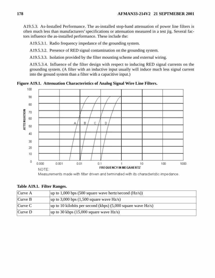
178 AFMAN33-214V2 21 SEPTMEBER 2001
A19.5.3. As-Installed Performance. The as-installed stop-band attenuation of power line filters isoften much less than manufacturers’ specifications or attenuation measured in a test jig. Several fac-tors influence the as-installed performance. These include the:
A19.5.3.1. Radio frequency impedance of the grounding system.
A19.5.3.2. Presence of RED signal contamination on the grounding system.
A19.5.3.3. Isolation provided by the filter mounting scheme and external wiring.
A19.5.3.4. Influence of the filter design with respect to inducing RED signal currents on thegrounding system. (A filter with an inductive input usually will induce much less signal currentinto the ground system than a filter with a capacitive input.)
Figure A19.1. Attenuation Characteristics of Analog Signal Wire Line Filters.
Table A19.1. Filter Ranges.
Curve A up to 1,000 bps (500 square wave hertz/second (Hz/s))
Curve B up to 3,000 bps (1,500 square wave Hz/s)
Curve C up to 10 kilobits per second (kbps) (5,000 square wave Hz/s)
Curve D up to 30 kbps (15,000 square wave Hz/s)

AFMAN33-214V2 21 SEPTMEBER 2001 179
Attachment 20
MAINTENANCE OF SHIELDED ENCLOSURES
A20.1. Introduction. This attachment provides guidance for properly maintaining shielded enclosures.Test, inspect, and maintain enclosures periodically during operational use.
A20.2. Inspections. The frequency of inspections depends on the extent of its use. Following is a sug-gested inspection schedule for enclosures: perform maintenance as required.
A20.2.1. Daily. Doors with finger stock used more than ten times a day.
A20.2.2. Weekly. Doors with finger stock used less than ten times a day.
A20.2.3. Monthly. Doors not using finger stock, filters, air ducts, and motor generator (if used).
A20.2.4. Annually. Joints, panels, and roof (include leakage tests).
A20.2.5. Every 3 Years. Conduct a shielding effectiveness test as part of the facility recertificationaccording to paragraph 8.51.5.6.
A20.3. Door and Frame Maintenance.
A20.3.1. Cleaning. Clean the contact surfaces of the door and frame with steel wool to remove alltraces of corrosion, floor wax, or other nonconducting material. Take care to avoid deforming the fin-ger stock.
A20.3.2. Finger Stock. Bent or deformed finger stock is restored to its original shape with awide-blade screwdriver, flat piece of rigid metal, or long-nose pliers. Take care to avoid deformingfingers adjacent to those being adjusted. Cut away broken fingers from the door with sheet metalshears. Replacements are then soldered into place.
A20.3.3. Latch and Lock.
A20.3.3.1. Adjust the position of the striker plate if the door is difficult to close and the strikerplate or latch shows excessive wear.
A20.3.3.2. Replace the knit-metal gasket around the shaft if the enclosure door has a built-in lockand if radio frequency checks reveal leakage around it.
A20.3.3.3. Notify the enclosure manufacturer if the door is not repairable by the techniquesdescribed above.
A20.3.4. Scored Door Frame. Attaching brass plates to the face of the doorframe prevents deep dentsin the doorframe caused by attempts to close the door with the latches protruding. Dents on the contactsurface are filled with solder and sanded flat.
A20.3.5. Sagging Door. If the door scrapes its frame during normal operation, or if the depth of thecontact pattern is irregular, the door is sagging. If the hinges are intact, the door position is adjusted byloosening the hinge screws, shifting the door to its proper position, and retightening the screws. If thehinges are badly worn, replace with steel hinges.
A20.3.6. Acoustic Seal. A worn or broken acoustic gasket, misalignment of the door, or unintentionalmetal-to-metal contact between the door and its frame may cause acoustic leakage around the door.
180 AFMAN33-214V2 21 SEPTMEBER 2001
Design details of acoustic seals vary with the manufacturer, but they generally include adjustableframing strips and rubber gaskets. Remove worn, flattened, or torn gaskets and glue replacements tothe door. Adjust framing strips only as a last resort, since alignment is critical.
A20.4. Air Duct Cleaning. Frequent cleaning or replacement of the air filter in the air conditioner pre-vents clogging of the waveguide air vents. If these vents require cleaning, use a vacuum cleaner and anaerosol grease solvent. Do not remove the vents from the shield since reinstallation with a good radio fre-quency joint is difficult.
A20.5. Repair of Acoustic Ducts. Acoustic leakage from these ducts is usually caused by unintentionalcontact between metal ductwork and the radio frequency shield or by sagging ducts that compress theacoustic gaskets. Holes or worn spots, particularly in the nonmetallic parts, also cause leaks. Repair tech-niques are usually self-evident.
A20.6. Major Structural Repairs. Tighten, with a torque wrench, loose joints in bolted enclosuresdetected during radio frequency leakage tests. For inside bolted enclosures, this requires removing allinterior materials that cover the leaking joint. If these include acoustic materials, reinstall carefully to pre-vent subsequent acoustic leakage. The enclosure manufacturer repairs major structural failures, such as asagging roof, warped panels, or deformed floor. Replace or patch, if appropriate, torn foil panels. If a tearoccurs in a panel covering plywood or other solid surface, apply a patch by using a conductive adhesivemastic around the tear and placing a patch of foil that covers the hole or tear completely and extendsbeyond it by at least four inches. When a tear occurs between studs or fir strips, replace the panel or placean additional foil panel on top of the torn section making a third layer of the particular section.

AFMAN33-214V2 21 SEPTMEBER 2001 181
Attachment 21
APPLYING ADMINISTRATIVE COMMUNICATIONS COUNTERMEASURES
A21.1. Introduction. Do not apply these countermeasures unless the EMSEC countermeasures reviewusing one of the Attachment 6 through Attachment 14 directs you into this attachment. This attachmentprovides commonly required administrative communications countermeasures. Due to the amount ofinformation and the number of times they are required, they were placed in this attachment to conservespace.
A21.2. BLACK Intercom and Public Address Systems.
A21.2.1. Required Application. Do the following when application of this countermeasure isrequired.
A21.2.1.1. A wireless intercom system (radio frequency transmitter) is prohibited in all cases.
A21.2.1.2. Contain the system totally within the inspectable space.
A21.2.1.3. Install the public address amplifier in a metal cabinet to contain any free-space radia-tion it might generate.
A21.2.1.4. Separate wire lines according to the separation requirements in the appropriate coun-termeasures review attachment.
A21.2.2. Selected for Application. Do the following when this countermeasure has been consideredand selected for application.
A21.2.2.1. A wireless intercom system (radio frequency transmitter) is prohibited in all cases.
A21.2.2.2. Contain the system totally within the inspectable space.
A21.2.2.3. Separate wire lines according to the separation requirements in the applicable counter-measures review attachment.
A21.3. Comfort Music Systems. There are two types of comfort music systems--those that use a radioreceiver and those that do not. Take the following precautions to reduce the risk of the system becomingan escape medium for compromising emanations. Systems that do not use a radio receiver include sys-tems like compact disk (CD) or play-only tape players.
A21.3.1. Required Application. Do the following when application of this countermeasure isrequired.
A21.3.1.1. Contain the entire music system, including speakers and associated cables, within theinspectable space. The user may need two music systems at some locations, one for within theinspectable space and one for outside the inspectable space.
A21.3.1.2. Use shielded audio cable, as described in Attachment 18, between the receiver andspeakers. Separate according to the requirements established for shielded wire lines in the applica-ble countermeasures review attachment.
A21.3.1.3. Use "open type" speakers (that is, ceiling mount or open box) for easy inspection.
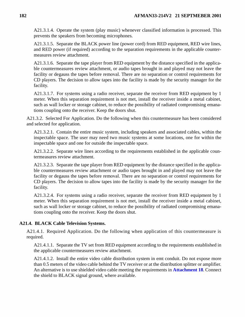
182 AFMAN33-214V2 21 SEPTMEBER 2001
A21.3.1.4. Operate the system (play music) whenever classified information is processed. Thisprevents the speakers from becoming microphones.
A21.3.1.5. Separate the BLACK power line (power cord) from RED equipment, RED wire lines,and RED power (if required) according to the separation requirements in the applicable counter-measures review attachment.
A21.3.1.6. Separate the tape player from RED equipment by the distance specified in the applica-ble countermeasures review attachment, or audio tapes brought in and played may not leave thefacility or degauss the tapes before removal. There are no separation or control requirements forCD players. The decision to allow tapes into the facility is made by the security manager for thefacility.
A21.3.1.7. For systems using a radio receiver, separate the receiver from RED equipment by 1meter. When this separation requirement is not met, install the receiver inside a metal cabinet,such as wall locker or storage cabinet, to reduce the possibility of radiated compromising emana-tions coupling onto the receiver. Keep the doors shut.
A21.3.2. Selected For Application. Do the following when this countermeasure has been consideredand selected for application.
A21.3.2.1. Contain the entire music system, including speakers and associated cables, within theinspectable space. The user may need two music systems at some locations, one for within theinspectable space and one for outside the inspectable space.
A21.3.2.2. Separate wire lines according to the requirements established in the applicable coun-termeasures review attachment.
A21.3.2.3. Separate the tape player from RED equipment by the distance specified in the applica-ble countermeasures review attachment or audio tapes brought in and played may not leave thefacility or degauss the tapes before removal. There are no separation or control requirements forCD players. The decision to allow tapes into the facility is made by the security manager for thefacility.
A21.3.2.4. For systems using a radio receiver, separate the receiver from RED equipment by 1meter. When this separation requirement is not met, install the receiver inside a metal cabinet,such as wall locker or storage cabinet, to reduce the possibility of radiated compromising emana-tions coupling onto the receiver. Keep the doors shut.
A21.4. BLACK Cable Television Systems.
A21.4.1. Required Application. Do the following when application of this countermeasure isrequired.
A21.4.1.1. Separate the TV set from RED equipment according to the requirements established inthe applicable countermeasures review attachment.
A21.4.1.2. Install the entire video cable distribution system in emt conduit. Do not expose morethan 0.5 meters of the video cable behind the TV receiver or at the distribution splitter or amplifier.An alternative is to use shielded video cable meeting the requirements in Attachment 18. Connectthe shield to BLACK signal ground, where available.

AFMAN33-214V2 21 SEPTMEBER 2001 183
A21.4.1.3. Separate video cables by the distance specified in the applicable countermeasuresreview attachment.
A21.4.1.4. Separate the BLACK power line (power cord) from RED equipment, RED wire lines,and RED power (if required) according to the separation requirements in the applicable counter-measures review attachment.
A21.4.1.5. Isolate the video cable. This is best done at the boundary of the inspectable space topreclude the video cable from becoming recontaminated with compromising emanations. This isnot always practical but isolation must be done beyond the ERTZ or the cable must be shielded orinstalled in emt conduit. There are three generally acceptable methods for isolating the cable.
A21.4.1.5.1. Method One. Use a photon-coupled (optical) isolator, as described in Attach-ment 19, to break the electrical connection for conducted emanations and to filter out anyemanations that may have modulated the TV receiver.
A21.4.1.5.2. Method Two. Use a combination of attenuation and amplification to reduce bothconducted and modulated emanations. Use a combination of the front-to-back ratio of theamplifier and additional attenuation (for example, using an amplifier with a 70-dBfront-to-back ratio and a 30-dB attenuator will provide the required 100 dB of isolation). Setthe gain of the amplifier for optimal operation, usually unity gain (enough to overcome thedecrease in signal level caused by the attenuator). The minimum acceptable attenuation is 100dB. Do not use an amplifier that can amplify signals in both directions.
A21.4.1.5.3. Method Three. For a single TV receiver, a VCR can provide the video serviceand will also act as a “one way” filter. If a control box is used, collocate it with the VCR. Dis-connect the incoming video cable before using the VCR for processing classified information.
A21.4.1.6. If using an active cable splitter or amplifier to distribute the video signal within thefacility, separate the splitter or amplifier by the distance specified in the applicable countermea-sures review attachment from RED equipment. If this separation requirement is not met, install thesplitter or amplifier inside a metal container or cabinet, such as wall locker or storage cabinet, toreduce the possibility of radiated compromising emanations coupling onto the splitter or amplifier.Shield the incoming lines to a distance of at least one-third the ERTZ of the RED equipment.
A21.4.2. Selected for Application. Do the following when this countermeasure has been consideredand selected for application.
A21.4.2.1. Separate the TV set from RED equipment according to the requirements established inthe applicable countermeasures review attachment.
A21.4.2.2. Separate video cables by the distance specified in the applicable countermeasuresreview attachment.
A21.4.2.3. Separate the BLACK power line (power cord) from RED equipment, RED wire lines,and RED power (if required) according to the separation requirements in the applicable counter-measures review attachment.
A21.4.2.4. If using an active cable splitter or amplifier to distribute the video signal within thefacility, separate the splitter or amplifier by the distance specified in the applicable countermea-sures review attachment from RED equipment.
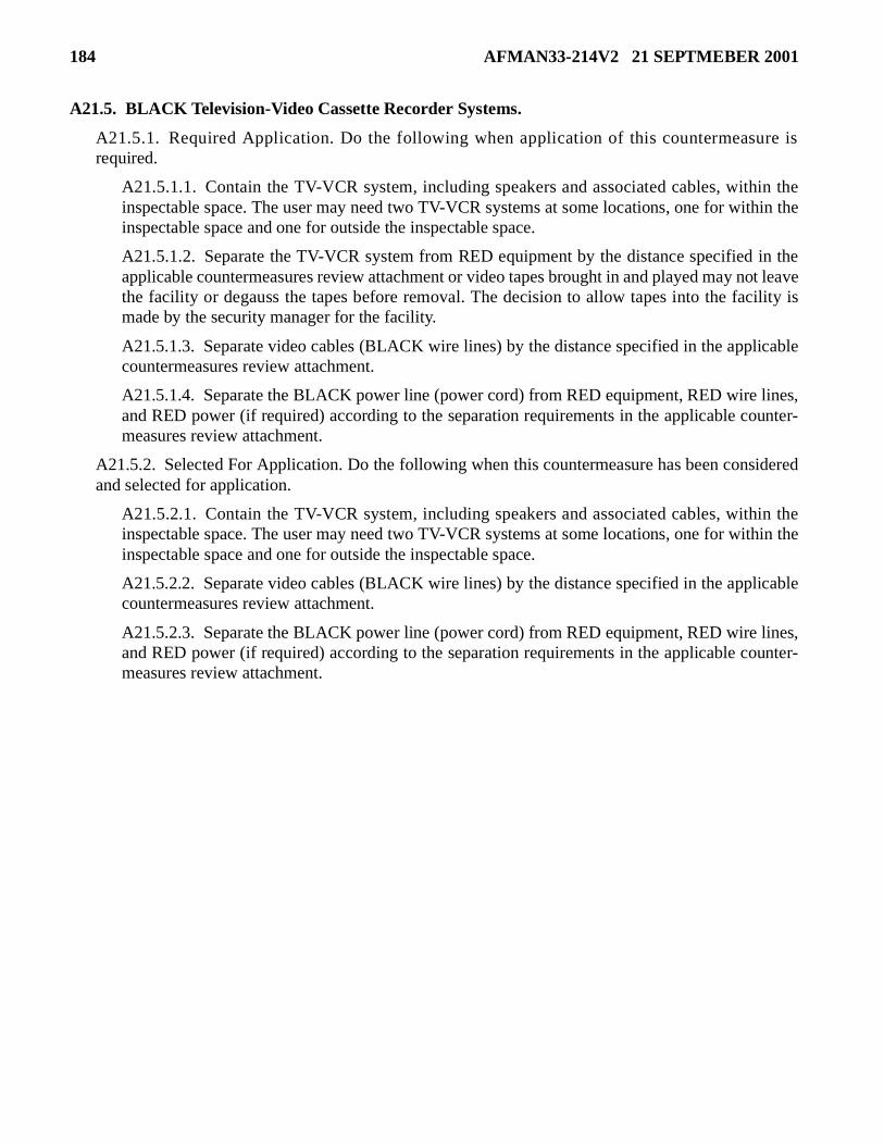
184 AFMAN33-214V2 21 SEPTMEBER 2001
A21.5. BLACK Television-Video Cassette Recorder Systems.
A21.5.1. Required Application. Do the following when application of this countermeasure isrequired.
A21.5.1.1. Contain the TV-VCR system, including speakers and associated cables, within theinspectable space. The user may need two TV-VCR systems at some locations, one for within theinspectable space and one for outside the inspectable space.
A21.5.1.2. Separate the TV-VCR system from RED equipment by the distance specified in theapplicable countermeasures review attachment or video tapes brought in and played may not leavethe facility or degauss the tapes before removal. The decision to allow tapes into the facility ismade by the security manager for the facility.
A21.5.1.3. Separate video cables (BLACK wire lines) by the distance specified in the applicablecountermeasures review attachment.
A21.5.1.4. Separate the BLACK power line (power cord) from RED equipment, RED wire lines,and RED power (if required) according to the separation requirements in the applicable counter-measures review attachment.
A21.5.2. Selected For Application. Do the following when this countermeasure has been consideredand selected for application.
A21.5.2.1. Contain the TV-VCR system, including speakers and associated cables, within theinspectable space. The user may need two TV-VCR systems at some locations, one for within theinspectable space and one for outside the inspectable space.
A21.5.2.2. Separate video cables (BLACK wire lines) by the distance specified in the applicablecountermeasures review attachment.
A21.5.2.3. Separate the BLACK power line (power cord) from RED equipment, RED wire lines,and RED power (if required) according to the separation requirements in the applicable counter-measures review attachment.

AFMAN33-214V2 21 SEPTMEBER 2001 185
Attachment 22
AIR FORCE FORM 4170, EMISSION SECURITY ASSESSMENTS
A22.1. Figure A22.1., Figure A22.2., and Figure A22.3. are samples of a completed AF Form 4170.

186 AFMAN33-214V2 21 SEPTMEBER 2001
Figure A22.1. AF Form 4170, Emission Security Assessments (Page 1).

AFMAN33-214V2 21 SEPTMEBER 2001 187
Figure A22.2. AF Form 4170, Emission Security Assessments (Page 2).
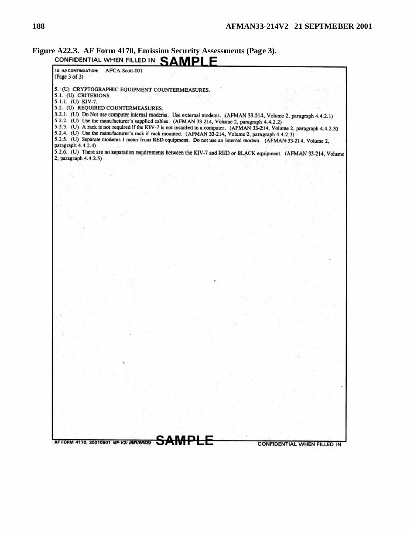
188 AFMAN33-214V2 21 SEPTMEBER 2001
Figure A22.3. AF Form 4170, Emission Security Assessments (Page 3).