Embed Size (px)
Citation preview

BY ORDER OF THE COMMANDER
AIR FORCE SPACE COMMAND
AIR FORCE SPACE COMMAND MANUAL
91-710 VOLUME 3
1 JULY 2004
Incorporating Change 1, 15 DECEMBER 2015
Safety
RANGE SAFETY USER REQUIREMENTS
MANUAL VOLUME 3 LAUNCH VEHICLES,
PAYLOADS, AND GROUND SUPPORT
SYSTEMS REQUIREMENTS
COMPLIANCE WITH THIS PUBLICATION IS MANDATORY
ACCESSIBILITY: Publications and forms are available on the e-Publishing website at
www.e-publishing.af.mil for downloading or ordering.
RELEASABILITY: There are no releasability restrictions on this publication.
OPR: AFSPC/SEC (Lt Col John
Humphries)
Certified by: AFSPC/SE
(Col Billy Colwell)
Pages: 244
This manual implements Department of Defense Directive (DoDD) 3100.10, Space Policy,
DoDD 3200.11, Major Range and Test Facility Base, DoDD 3230.3, DoD Support for
Commercial Space Launch Activities, AFPD 91-1, Nuclear Weapons and Systems Surety, AFPD
91-2, Safety Programs, AFI 91-202_AFSPCSUP_I, The US Air Force Mishap Prevention
Program and the Memorandum of Agreement between the Department of the Air Force and the
Federal Aviation Administration on Safety for Space Transportation and Range Activities. This
volume contains information previously found in Eastern and Western Range 127-1, Chapter 3,
Launch Vehicle, Payload, and Ground Support Equipment Documentation, Design, and Test
Requirements. It establishes the system safety program requirements, minimum design, test,
inspection, hazard analyses, and data requirements for hazardous and safety critical launch
vehicles, payloads, and ground support equipment, systems, and materials for Air Force Space
Command (AFSPC) ranges, including the Eastern Range (ER) and Western Range (WR). The
following topics are addressed: general design policy, documentation requirements, operations
safety console, material handling equipment, acoustic hazards, non-ionizing radiation sources,
radioactive (ionizing radiation) sources, hazardous materials, ground support pressure systems,
flight hardware pressure systems, ordnance systems, electrical and electronic equipment, motor

2 AFSPCMAN91-710V3 1 JULY 2004
vehicles, computer systems and software, seismic design criteria (WR only), and solid rocket
motors and motor segments. This volume applies to all Range Users conducting or supporting
operations on the AFSPC ranges. Range Users include any individual or organization that
conducts or supports any activity on resources (land, sea, or air) owned or controlled by AFSPC
ranges. This includes such organizations as the Department of Defense (DoD), United States
(US) government agencies, civilian launch operators, and foreign government agencies and other
foreign entities that use AFSPC range facilities and test equipment; conduct prelaunch and
launch operations, including payloads to orbital insertion or impact; and/or require on-orbit or
other related support. Commercial users intending to provide launch services from one of the
ranges shall have a license or license application in process from the Department of
Transportation's Federal Aviation Administration (FAA) or have a DoD sponsorship and be
accepted by the DoD to use the ER or WR. Foreign government organizations or other foreign
entities shall be sponsored by an appropriate US government organization or be a customer of a
Range User. This volume applies to the Air National Guard. It does not apply to the Air Force
Reserve Command. Ensure all records created as a result of processes prescribed in this
publication are maintained IAW Air Force Manual (AFMAN) 33-363, Management of Records,
and disposed of IAW Air Force Records Information System (AFRIMS) Records Disposition
Schedule (RDS). Refer recommended changes and questions about this publication to the Office
of Primary Responsibility (OPR) using the AF Form 847, Recommendation for Change of
Publication, route AF Forms 847 from the field through the appropriate functional chain of
command. This publication may be supplemented at any level, but all direct Supplements must
be routed to the OPR of this publication for coordination prior to certification and approval.
Request for waivers though the chain of command to the appropriate Tier waiver approval
authority, or alternately, to the Publication OPR for non-tiered compliance items. The
requirements in this publication are waived at a Tier 3 level. NOTE: Volume 1 includes a
complete table of contents for all the volumes of AFSPCMAN 91-710. In addition, each
individual volume contains its own table of contents. Volume 7 contains a glossary of
references, acronyms and abbreviations, and terms for use with all the volumes. Special
publication formatting features are described in 1.2 of this volume.
SUMMARY OF CHANGES
This interim change revises the opening paragraph of this publication to include the Records
Management, Recommending Changes, Supplementing Publication and Waiver Authority
Statement to be in compliance with AFI 33-360, Publications and Forms Management. A
margin bar (ǀ) indicates newly revised material.
CHAPTER 1—INTRODUCTION 7
1.1. General: .................................................................................................................. 7
1.2. Organization of the Volume: ................................................................................. 7
CHAPTER 2—RESPONSIBILITIES AND AUTHORITIES 9
2.1. Range Safety, 30th and 45th Space Wings: ........................................................... 9
2.2. Range User Responsibilities. ................................................................................. 9

AFSPCMAN91-710V3 1 JULY 2004 3
CHAPTER 3—GENERAL DESIGN POLICY 10
3.1. General: .................................................................................................................. 10
3.2. Systems Without Specific Design Criteria. ........................................................... 10
CHAPTER 4—DOCUMENTATION REQUIREMENTS 11
4.1. System Safety Program Plan and Hazard Analyses: .............................................. 11
4.2. Missile System Prelaunch Safety Package: ........................................................... 11
4.3. MSPSP Associated Test Plans and Test Results: ................................................... 12
4.4. Nondestructive Examination Plans: ....................................................................... 12
CHAPTER 5—OPERATIONS SAFETY CONSOLE 13
5.1. Operations Safety Console General Design Requirements: .................................. 13
5.2. ER OSC Controls, Monitors, and Communication Lines: ..................................... 13
5.3. WR OSC Controls, Monitors, and Communication Lines: ................................... 14
5.4. OSC Color Television System: .............................................................................. 15
5.5. OSC Communication and Video Recording: ......................................................... 15
5.6. OSC Validation and Test Requirements: ............................................................... 15
5.7. OSC Data Requirements. ....................................................................................... 16
CHAPTER 6—MATERIAL HANDLING EQUIPMENT, CRANES AND HOISTS, AND
PERSONNEL WORK PLATFORMSTHIS CHAPTER IS DIVIDED INTO
THREE MAJOR TYPES OF EQUIPMENT: MATERIAL HANDLING
EQUIPMENT (MHE). CRANES AND HOISTS AND PERSONNEL
WORK PLATFORMS. 17
6.1. Material Handling Equipment: .............................................................................. 17
6.2. Cranes and Hoists. ................................................................................................. 24
6.3. Removable, Extendible, and Hinged Personnel Work Platforms. ......................... 36
6.4. Man-Rated Baskets. ............................................................................................... 37
CHAPTER 7—ACOUSTIC HAZARDS 38
7.1. Acoustic Design Standards: ................................................................................... 38
7.2. Acoustic Data Requirements. ................................................................................. 38
CHAPTER 8—NON-IONIZING RADIATION SOURCES 39
8.1. Radio Frequency Emitters. ..................................................................................... 39
8.2. Laser Systems: ....................................................................................................... 40
CHAPTER 9—RADIOACTIVE (IONIZING) RADIATION SOURCES 43
9.1. Radioactive Source Design Standards and Controls: ............................................. 43
4 AFSPCMAN91-710V3 1 JULY 2004
9.2. Radioactive Sources Carried on Launch Vehicles and Payloads. .......................... 44
CHAPTER 10—HAZARDOUS MATERIALS 46
10.1. Hazardous Materials Selection Criteria: ................................................................ 46
10.2. Hazardous Materials Test Requirements: .............................................................. 46
10.3. Hazardous Materials Environmental Requirements: ............................................. 47
10.4. Hazardous Material Data Requirements. ............................................................... 47
10.5. Process Safety Management and Risk Management Plan: .................................... 47
CHAPTER 11—GROUND SUPPORT PRESSURE, VACUUM, AND HAZARDOUS
STORAGE SYSTEMS 48
11.1. Ground Support Pressure Vacuum and Storage Systems Requirements: .............. 48
11.2. Ground Support Pressure Systems Requirements: ................................................. 48
Table 11.1. Sheet/Plate Material Stainless Steel Properties. ..................................................... 51
Table 11.2. Open Line Force Calculation Factor. ..................................................................... 68
Table 11.3. Spacing for Tubing Supports Within Consoles or Modules. ................................. 72
Table 11.4. Spacing for Tubing Supports Between Consoles or Modules. .............................. 73
11.3. Ground Support Pressure Systems Certification and Recertification: ................... 86
CHAPTER 12—FLIGHT HARDWARE PRESSURE SYSTEMS AND PRESSURIZED
STRUCTURES 92
12.1. Flight Hardware Pressure System and Pressurized Structure General
Requirements. ........................................................................................................ 92
Table 12.1. Open Line Force Calculation Factor. ..................................................................... 101
12.2. Flight Hardware pressure Vessel Design, Analysis, and Test Requirements: ....... 112
Figure 12.1. Pressure Vessel Design Verification Approach. .................................................... 113
Table 12.2. Qualification Pressure Test Requirements. ............................................................ 116
12.3. Flight Hardware Metallic Pressurized Structure Analysis and Test Requirements:
................................................................................................................................. 124
12.4. Flight Hardware Special Pressurized Equipment Design, Analysis, and Test
Requirements. ........................................................................................................ 128
12.5. Flight Hardware Pressure System Component Design and Test Requirements. ... 134
Table 12.3. Pressure Components Safety Factors. .................................................................... 135
Table 12.4. Limit Torque Requirements. .................................................................................. 141
12.6. Flight Hardware Pneumatic System Design Requirements. .................................. 146
12.7. Flight Hardware Hydraulic System Design and Test Requirements. .................... 149
12.8. Flight Hardware Hypergolic Propellant System Design and Test Requirements: . 150

AFSPCMAN91-710V3 1 JULY 2004 5
12.9. Flight Hardware Cryogenic Systems Design and Test Requiremetns: .................. 155
12.10. Flight Hardware Pressure Systems Data Requirements: ........................................ 159
CHAPTER 13—ORDNANCE SYSTEMS 162
13.1. Ordnance Hazard Classification: ........................................................................... 162
13.2. Ordnance System General Requirements. ............................................................. 163
13.3. Ordnance Electrical and Optical Circuits: ............................................................. 163
13.4. Initiator Electrical and Optical Circuits: ................................................................ 167
13.5. Ordnance Safety Devices: ...................................................................................... 170
13.6. Ordnance Initiating Devices: ................................................................................. 179
Table 13.1. RF Sensitivity. ....................................................................................................... 182
13.7. Explosive Transfer Systems and Receptor Ordnance. ........................................... 184
13.8. Odnance Test Equipment: ...................................................................................... 185
13.9. Ordnance Data Requirements. ............................................................................... 187
CHAPTER 14—ELECTRICAL AND ELECTRONIC EQUIPMENT 188
14.1. Electrical and Electronic Ground Support Equipment and Flight Hardware
General Design ...................................................................................................... 188
14.2. EGSE Design Requirements: ................................................................................. 191
14.3. Electrical and Electronic Flight Hardware: ............................................................ 195
CHAPTER 15—MOTOR VEHICLES 199
15.1. General: .................................................................................................................. 199
15.2. Motor Vehicles Other Than Lift Trucks: ............................................................... 199
15.3. Lift Trucks: ............................................................................................................ 200
CHAPTER 16—COMPUTER SYSTEMS AND SOFTWARE 202
16.1. General: .................................................................................................................. 202
16.2. Determination of Safety Critical Computer System Functions. ............................. 202
16.3. Hardware and Software Safety Design Requirements. .......................................... 203
16.4. Software Requirements: ......................................................................................... 206
16.5. Computer System and Software Data Requirements. ............................................ 208
CHAPTER 17—WR SEISMIC DESIGN 209
17.1. Applicability of Design and/or Anchorage or Restraint Requirements: ................ 209
17.2. Basis for Design: .................................................................................................... 209
17.3. WR Seismic Data Requirements. ........................................................................... 210

6 AFSPCMAN91-710V3 1 JULY 2004
CHAPTER 18—SOLID ROCKET MOTORS AND ROCKET MOTOR SEGMENTS 211
18.1. General. .................................................................................................................. 211
18.2. FMECA and OHA. ................................................................................................ 211
18.3. Lightning Effects Hazard Analysis. ....................................................................... 211
18.4. Solid Rocket Motor and Motor Segment Data Requirements. .............................. 211
ATTACHMENT 1—MISSILE SYSTEM PRELAUNCH SAFETY PACKAGE 212
ATTACHMENT 2—HANDLING STRUCTURES INITIAL AND PERIODIC TEST
REQUIREMENT FLOWPATH 238
ATTACHMENT 3—HAZARDOUS AREA CLASSIFICATION 242
AFSPCMAN91-710V3 1 JULY 2004 7
Chapter 1
INTRODUCTION
1.1. General:
1.1.1. All Range Users operating on the AFSPC ranges, including the ER and WR, are
subject to the requirements of this volume to ensure safety by design, testing, inspection, and
hazard analysis. Air Force Occupational Safety and Health (AFOSH) standards do not apply
to contractors or contractor employees except where Air Force personnel or property are
endangered or if specifically required by contract.
1.1.2. The Space Shuttle Payload Ground Safety Handbook (KHB 1700.7) design
requirements may be used in lieu of the design requirements of this volume only for payloads
intended to fly on the Space Shuttle. Systems not addressed in KHB 1700.7 shall meet the
requirements of this volume. For expendable launch vehicle payloads processed in the
National Aeronautics and Space Administration (NASA) Kennedy Space Center (KSC)
payload processing facilities, ground support equipment (GSE) may be designed to the
requirements of KHB 1700.7 instead of AFSPCMAN 91-710 if the GSE is used only on KSC
property.
1.2. Organization of the Volume:
1.2.1. Main Chapters. The main chapters of this volume include common requirements for
all vehicle classes. Appendixes include additional requirements to supplement the main
chapters.
1.2.2. Open Text. The open text contains the actual mandatory performance-based
requirements. The only tailoring expected for these requirements would be the deletion of
non-applicable requirements. For example, solid rocket motor performance requirements
would be deleted for launch systems that do not use solid rocket motors.
1.2.3. Bordered Paragraphs:
1.2.3.1. Bordered paragraphs are non-mandatory and are used to identify some of the
potential detailed technical solutions that meet the performance requirements. In addition,
the bordered paragraphs contain lessons learned from previous applications of the
performance requirement, where a certain design may have been found successful, or
have been tried and failed to meet the requirement. These technical solutions are provided
for the following reasons:
1.2.3.1.1. To aid the tailoring process between Range Safety and Range Users in
evaluating a potential system against all the performance requirements.
1.2.3.1.2. To aid Range Safety and Range Users in implementing lessons learned.
1.2.3.1.3. To provide benchmarks that demonstrate what Range Safety considers an
acceptable technical solution/implementation of the performance requirement and to
help convey the level of safety the performance requirement is intended to achieve.
1.2.3.2. The technical solutions in the bordered paragraphs may be adopted into the
tailored version of the requirements for a specific program when the Range User intends

8 AFSPCMAN91-710V3 1 JULY 2004
to use that solution to meet the performance requirement. At this point, they become
mandatory requirements to obtain Range Safety approval. This process is done to:
1.2.3.2.1. Provide an appropriate level of detail necessary for contractual efforts and
to promote efficiency in the design process.
1.2.3.2.2. Avoid contractual misunderstandings that experience has shown often
occur if an appropriate level of detail is not agreed to. The level of detail in the
bordered paragraphs is necessary to avoid costly out-of-scope contractual changes
and to prevent inadvertently overlooking a critical technical requirement.
1.2.3.3. The Range User always has the option to propose alternatives to the bordered
paragraph solutions. Range User proposed alternative solutions shall achieve an
equivalent level of safety and be approved by Range Safety. After meeting these two
requirements, the Range User proposed solutions become part of the tailored
AFSPCMAN 91-710 for that specific program.
1.2.3.4. Range Safety has final decision authority in determining whether Range User
proposed detailed technical solutions meet AFSPCMAN 91-710 performance
requirements.

AFSPCMAN91-710V3 1 JULY 2004 9
Chapter 2
RESPONSIBILITIES AND AUTHORITIES
2.1. Range Safety, 30th and 45th Space Wings:
2.1.1. Unless otherwise noted, all references to Range Safety in this volume refer to the
Systems Safety organizations of the 30th and 45th Space Wings. The Range Safety offices
are responsible for the review and approval of the design, inspection, and testing of all
hazardous and safety critical launch vehicles, payloads, and ground support equipment,
systems, subsystems, and material to be used at the ER and WR in accordance with the
requirements of this volume. The responsibilities of Range Safety at the 45th Space Wing
may also encompass designs of launch vehicles, payloads, ground support equipment,
systems, subsystems and material used at the NASA Kennedy Space Center. Specific
responsibilities of Range Safety include review and approval of documents such as Missile
System Prelaunch Safety Packages (MSPSPs), System Safety Program Plans (SSPPs), test
plans, test reports, and other documents as specified in this manual.
2.1.2. During the review and approval process, both Range Safety and the Range User shall
assure timely coordination with other Wing agencies as appropriate. Other Wing agencies
include, but are not limited to, Radiation Protection Officer, Bioenvironmental Engineering,
Civil Engineering, Environmental Planning, Explosive Ordnance Disposal, and the Fire
Department.
2.2. Range User Responsibilities. Range Users are responsible for establishing and
maintaining a system safety program in accordance with Volume 1, Attachment 2 of this
publication and the design, inspection, and testing of all hazardous and safety critical launch
vehicle, payload, and ground support equipment, systems, subsystems, and materials to be used
at the ranges in accordance with the requirements of this volume. These responsibilities include
the following:
2.2.1. Timely submission of an SSPP.
2.2.2. Timely submission of hazard analyses.
2.2.3. Timely submission of all required Missile System Prelaunch Safety Packages
(MSPSPs).
2.2.4. Timely submission of all MSPSP associated Test Plans and Test Reports.
2.2.5. Coordinating with and supporting Range Safety in carrying out tasks necessary for
Range Safety approval of design, inspection, and testing.

10 AFSPCMAN91-710V3 1 JULY 2004
Chapter 3
GENERAL DESIGN POLICY
3.1. General:
3.1.1. All systems shall be designed to tolerate a minimum number of credible failures.
3.1.2. The number of design inhibits required to prevent an overall system failure or mishap
is based on the failure or mishap result. Specific inhibit requirements are addressed in the
design criteria for each of the systems addressed in this volume.
3.2. Systems Without Specific Design Criteria. Those systems that do not have specific
design criteria or systems not addressed in this volume shall be designed to the following general
criteria:
3.2.1. If a system failure may lead to a catastrophic hazard, the system shall have three
inhibits (dual fault tolerant).
3.2.2. If a system failure may lead to a critical hazard, the system shall have two inhibits
(single fault tolerant).
3.2.3. If a system failure may lead to a marginal hazard, the system shall have a single
inhibit (no fault tolerant).
3.2.4. Probabilities of hazard occurrence shall be taken into consideration when determining
the number of required inhibits. (See Volume 1, Chapter 3, Table 3.1.)
3.2.5. Systems shall be able to be brought to a safe state with the loss of an inhibit.
3.2.6. All inhibits shall be independent and verifiable. Common cause failures shall be
considered.
3.2.7. Design inhibits shall consist of electrical and/or mechanical hardware.
3.2.8. Operator controls shall not be considered a design inhibit. Operator controls are
considered a control of an inhibit.

AFSPCMAN91-710V3 1 JULY 2004 11
Chapter 4
DOCUMENTATION REQUIREMENTS
4.1. System Safety Program Plan and Hazard Analyses:
4.1.1. A preliminary SSPP shall be developed in accordance with Volume 1, Attachment 2
of this publication and submitted to Range Safety for review a minimum of 45 calendar days
before the conceptual Design Review (CDR). The Preliminary System Safety Program Plan
and Preliminary Hazard Analysis shall be developed in accordance with Volume 1,
Attachment 2 of this publication and shall be submitted to Range Safety prior to the
commencement of the tailoring process or prior to the Conceptual Design Review which ever
occurs first.
4.1.2. An SSPP shall be developed in accordance with Volume 1, Attachment 2 of this
publication and submitted to Range Safety for review a minimum of 45 calendar days before
the Preliminary Design Review (PDR).
4.1.3. Hazard analyses shall be developed and submitted to Range Safety for review and
approval in accordance with Volume 1, Attachment 2 of this publication.
4.1.3.1. Range Safety shall review and provide comments to each of the hazard analyses
submittals at or before the appropriate cDR, PDR, and Critical Design Review (CDR).
4.1.3.2. Final resolution of all hazards identified in the hazard analyses shall be
submitted to Range Safety for review and approval at least 45 calendar days before the
intended shipment of hardware to the ranges.
4.1.3.3. SSPPs and hazard analyses shall comply with MIL-STD-882, Department of
Defense Standard Practice for System Safety, data requirements.
4.2. Missile System Prelaunch Safety Package:
4.2.1. MSPSP Submittal, Review, and Approval Process:
4.2.1.1. Range Users shall submit an MSPSP for each new program such as launch
vehicle, payload, or stand-alone ground support equipment.
4.2.1.2. Range Safety shall review and provide comments to each of the MSPSP
submittals at or before the appropriate cDR, PDR, and CDR.
4.2.1.3. A final MSPSP that satisfies all Range Safety concerns addressed at the CDR
shall be submitted to Range Safety at least 45 calendar days before the intended shipment
of hardware to the ranges.
4.2.1.4. Range Safety shall review the MSPSP and, if the MSPSP is found to be
satisfactory, approve it within 10 calendar days of receipt. The final MSPSP shall be
approved before shipment of associated hardware to the ranges.
4.2.2. MSPSP Preparation. Requirements for preparing an MSPSP can be found in
Attachment 1 of this volume.

12 AFSPCMAN91-710V3 1 JULY 2004
4.3. MSPSP Associated Test Plans and Test Results:
4.3.1. All MSPSP associated test plans shall be submitted at least 45 calendar days before
the intended test plan use. Range User requests to eliminate or reduce testing shall be
justified with clear and convincing evidence presented to the SW/CC for approval. The
SW/CC may delegate approval authority to Range Safety.
4.3.2. Range Safety shall review and comment on or approve test plans within 45 calendar
days of receipt. Disapproved test plans shall be resubmitted. An approved test plan is
required before test performance.
4.3.3. Test reports shall be submitted at least 45 calendar days of intended system use.
4.3.4. Range Safety shall review, comment, and approve test reports within 10 calendar days
of receipt. Disapproved test reports shall be resubmitted. An approved test report is required
before system use.
4.4. Nondestructive Examination Plans:
4.4.1. Unless otherwise specified in a separate part of this document that addresses a
particular class of system or equipment, a nondestructive examination (NDE) plan shall
include the following:
4.4.1.1. NDE technique and acceptance criteria to be used on each single failure point
(SFP) component or SFP weld after initial and periodic proof load tests.
4.4.1.2. Detailed engineering rationale for each technique and acceptance criteria.
Detailed engineering rationale may include manufacturer stated
requirements/recommendations or recognized industry standards such as ANSI and ASME.
4.4.1.3. A determination of whether the equipment is dedicated to only one function or
whether it is multipurpose.
4.4.1.4. The environment and/or conditions under which the equipment will be used and
stored.
4.4.1.5. The existence of any SFP component and weld materials susceptible to stress
corrosion.
4.4.1.6. Corrosion protection and maintenance plans.
4.4.2. Unless otherwise specified in a separate part of this document that addresses a
particular class of system or equipment, the NDE plan shall be submitted to Range Safety for
review and approval as soon as developed and no later than the program PDR, unless
otherwise agreed to by Range Safety.

AFSPCMAN91-710V3 1 JULY 2004 13
Chapter 5
OPERATIONS SAFETY CONSOLE
5.1. Operations Safety Console General Design Requirements:
5.1.1. Each launch control center, blockhouse, and firing room, as applicable, shall provide
for an Operations Safety Console (OSC). MIL-STD-1472, Human Engineering Design
Criteria for Military Systems, Equipment, and Facilities, shall be used as guidance in
designing the Operations Safety Console.
5.1.2. The Range User (normally the launch vehicle provider) shall provide an ER/WR OSC
unless otherwise agreed to by Range Safety. Range Safety shall approve the design,
operation, and maintenance of the OSC.
5.1.3. The Range User shall provide ample and satisfactory space to install and operate the
console.
5.1.4. No SFP components shall be in the ground support equipment (GSE) or firing
room/launch control center/blockhouse system that will cause the loss of a safety critical
system control or monitor (as determined by Range Safety) at the OSC.
5.2. ER OSC Controls, Monitors, and Communication Lines:
5.2.1. The OSC shall be in a dedicated position to provide the Pad Safety Supervisor/Pad
Safety Officer sufficient information and communications capability to convey safety status
and conditions to the appropriate authority (the launch complex control authority for day-to-
day operations and the Mission Flight Control Officer [MFCO] during a launch operation).
5.2.2. At a minimum, the controls, monitors, and communication lines listed below are
required at the launch complex OSC. These items are general in nature and may vary
depending on the launch facility and/or launch vehicle configuration. The monitor circuit
shall be designed so that the actual status of the critical parameters can be monitored rather
than the command transmittal. It is important that this console does not have any flight
termination system (FTS) command transmittal functions.
5.2.2.1. FTS status (Refer to Volume 4 for requirements).
5.2.2.2. Ignition safe and arm status for all solid rocket motor safe and arm devices.
5.2.2.3. An enable control switch and status for all solid rocket motor arming devices.
5.2.2.4. Launch vehicle liquid propulsion system inhibits and propellant tank pressure
status (psig).
5.2.2.5. Water System (Pump Station):
5.2.2.5.1. Fire suppression system status.
5.2.2.5.2. Sound suppression system status.
5.2.2.5.3. Status for each main pump on-line or off-line.
5.2.2.6. Master Communications Control Panel:
5.2.2.6.1. Two administrative telephones with hold function.

14 AFSPCMAN91-710V3 1 JULY 2004
5.2.2.6.2. Audio-selector push buttons for intercom net and green phones (direct
line).
5.2.2.6.3. Green phones with a minimum of 30 channels.
5.2.2.6.4. Intercom capability via the Operational Information System (OIS) or
Transistorized Operational Phone System (TOPS) in which four channels can be
accessed simultaneously.
5.2.2.6.5. Paging capabilities.
5.2.2.6.6. Very high frequency/frequency modulation (VHF/FM) radio phone/.
5.2.2.6.7. Particular communication requirements shall be specified in applicable
Range Safety Operations Requirements (RSORs).
5.2.2.7. Master countdown status.
5.2.2.8. Holdfire (stop launch sequencer) control switch and status active through T-0.
5.2.2.9. Ignition firing line enable and disable control switch and status.
5.2.2.10. MFCO, Range Control Officer (RCO), and Range User holdfire status.
5.2.2.11. Emergency Panel:
5.2.2.11.1. Launch complex warning beacon and horn control switch and status.
5.2.2.11.2. Emergency and normal electrical power status for critical locations such
as the firing room and launch complex.
5.2.2.11.3. Status of the Range Command Transmitter carrier and Pilot Tone (on/off).
5.3. WR OSC Controls, Monitors, and Communication Lines:
5.3.1. The OSC shall be in a dedicated position to provide the Pad Safety Supervisor/Pad
Safety Officer sufficient information and communications capability to convey safety status
and conditions to the appropriate authority (the launch complex control authority for day-to-
day operations and the MFCO during a launch operation).
5.3.2. At a minimum, the controls, monitors, and communication needs listed below are
required at the launch complex OSC. These items are general in nature and may vary
depending on the launch vehicle configuration. The monitor circuit shall be designed so that
the actual status of the critical parameters can be monitored rather than the command
transmittal. It is important that this console not have any FTS command transmittal functions.
5.3.2.1. FTS safe and arm status for all FTS safe and arm devices.
5.3.2.2. Ignition safe and arm status for all solid rocket motor safe and arm devices.
5.3.2.3. Launch vehicle liquid propulsion system inhibits and propellant tank pressure
status (psig).
5.3.2.4. Communications:
5.3.2.4.1. Countdown net capable of monitoring and transmitting (redundant).
5.3.2.4.2. Direct line to the MFCO.

AFSPCMAN91-710V3 1 JULY 2004 15
5.3.2.4.3. Direct line to the RCO.
5.3.2.4.4. Direct line to Building 7000 Launch Operations Control Center (LOCC).
5.3.2.4.5. Direct lines to Test Conductor and Launch Control Officer.
5.3.2.4.6. Direct line to primary access control point for safety control areas.
5.3.2.4.7. Direct line to facility safety net.
5.3.2.4.8. Direct line to Launch Support Team Chief and fallback area.
5.3.2.4.9. Access to facility public address (PA) system with emergency override
capability.
5.3.2.4.10. At least one Class A dial line.
5.3.2.4.11. Radio Frequency (RF) nets, as required.
5.3.2.4.12. Direct line to the Launch Director.
5.3.2.4.13. Direct line to the Aeronautical Control Officer (ACO).
5.3.2.5. MFCO and Range User holdfire status.
5.3.2.6. Wind speed and direction readouts.
5.3.2.7. Complex and Range Clearance Status and Alert (S&A) lights to MFCO.
5.3.2.8. Launch complex warning lights and klaxon/horn switch and status indicators.
5.4. OSC Color Television System:
5.4.1. An OSC color television system shall be provided to ensure the coverage necessary to
view all hazardous operations in the launch complex.
5.4.2. Control of the television system shall be available at the OSC.
5.5. OSC Communication and Video Recording:
5.5.1. The OSC shall be capable of recording and playback of hazardous operations.
5.5.2. Communication and video recording requirements shall be coordinated with the
launch controller and test conductor before the start of an operation.
5.5.3. Designated recordings shall remain on file for 180 days.
5.6. OSC Validation and Test Requirements:
5.6.1. At a minimum, an OSC validation and checkout test shall be performed to
demonstrate the following:
5.6.1.1. The correct and reliable operation of OSC functions.
5.6.1.2. The validity of OSC outside interfaces.
5.6.1.3. The operating limits of the OSC.
5.6.2. Test plans, procedures, and test results shall be reviewed and approved by Range
Safety.

16 AFSPCMAN91-710V3 1 JULY 2004
5.7. OSC Data Requirements. OSC data requirements are identified in Attachment 1,
A1.2.5.16 of this volume.

AFSPCMAN91-710V3 1 JULY 2004 17
Chapter 6
MATERIAL HANDLING EQUIPMENT, CRANES AND HOISTS, AND PERSONNEL
WORK PLATFORMS THIS
CHAPTER IS DIVIDED INTO THREE MAJOR TYPES OF EQUIPMENT:
MATERIAL HANDLING EQUIPMENT (MHE). CRANES AND HOISTS AND
PERSONNEL WORK PLATFORMS.
6.1. Material Handling Equipment: The design and initial and periodic test requirements for
MHE used at the ranges for handling (lifting, supporting, or manipulating) critical and non-
critical hardware are included below.
6.1.1. MHE General Requirements:
6.1.1.1. MHE Requirements Validation:
6.1.1.1.1. The Range User shall validate the requirements by providing a Compliance
Check List in accordance with Attachment 1, A1.3 of this volume.
6.1.1.1.2. Supporting data for commercial-off-the-shelf (COTS) equipment shall
include the following information:
6.1.1.1.2.1. COTS name, description, model number, and part number.
6.1.1.1.2.2. Rated capacity.
6.1.1.1.2.3. Any applicable certifications or approvals; for example,
Underwriters’ Laboratories (UL) listing.
6.1.1.1.2.4. Applicable operating and maintenance (O&M) information, data,
and/or manuals.
6.1.1.2. MHE Single Fault Tolerance:
6.1.1.2.1. Critical MHE shall be designed without single failure points (SFPs).
6.1.1.2.2. Exceptions shall be identified, justified, and submitted to Range Safety for
approval. Supporting data shall include the following information: (See also
Attachment 1, A1.2.5.6 of this volume.)
6.1.1.2.2.1. A list of all identified SFPs.
6.1.1.2.2.2. Risk assessment.
6.1.1.2.2.3. Risk mitigation considerations and inhibits.
6.1.1.2.2.4. A map of SFP locations (for example, weld map, system
components).
6.1.1.2.2.5. NDE requirements.
6.1.1.2.3. SFP components and welds shall be accessible for nondestructive
inspection, maintenance, and repair.
6.1.1.3. MHE Inspection and Test Requirements:
6.1.1.3.1. MHE Test Weights and Load Test Devices:

18 AFSPCMAN91-710V3 1 JULY 2004
6.1.1.3.1.1. Load tests shall be conducted with certified weights and/or certified
weight fixtures.
6.1.1.3.1.2. These weights shall be identified and permanently and clearly
marked with the total weight and owner or agency identification number.
6.1.1.3.1.3. Reinforcing steel (rebar) shall not be used for lift points.
6.1.1.3.1.4. Calibrated load devices such as dynamometers may be used to test
slings and other lifting devices except cranes and hoists.
6.1.1.3.1.5. Requirements for Fabrication of New Test Weights and Weight
Fixtures:
6.1.1.3.1.5.1. Weight fixtures shall be designed and load tested in accordance
with requirements contained in 6.1.3.1.
6.1.1.3.1.5.2. Weight fixtures shall be designed so that the loaded fixture
center of gravity is centered below the crane hook for all required weight
combinations.
6.1.1.3.1.5.3. Lifting lugs shall be provided if required to enable handling of
empty test weight fixtures.
A single crane hook attachment point on the fixture for example a screw operated pin is
preferable to multiple attachment points that require use of slings.
6.1.1.3.1.5.4. Weight interlocking features shall be provided on both the
weight fixture and the weights to help prevent sliding of weights and to help
even stacking.
6.1.1.3.1.5.5. Weight lifting lugs shall be proof tested to 125 percent of the
total weight before initial weight use.
6.1.1.3.2. MHE NDE:
6.1.1.3.2.1. NDE plans shall be developed for MHE used to handle critical
systems and equipment and MHE containing SFPs.
6.1.1.3.2.2. The NDE plan shall include detailed methodology, acceptance
criteria, frequency of inspection, and a clear schematic showing the exact location
of the items to be inspected. For details of the NDE plan, see 4.4 of this volume.
6.1.1.3.2.3. NDE shall be performed by the Society for Nondestructive Testing –
Technical Council (SNT-TC) accredited personnel.
6.1.1.4. MHE Marking and Tagging Requirements:
6.1.1.4.1. Marking Requirements. All equipment (new and modified) shall be
permanently marked in accordance with applicable codes and standards and have a
permanently attached identification tag with the following information:
6.1.1.4.1.1. Manufacturer.
6.1.1.4.1.2. Part number.

AFSPCMAN91-710V3 1 JULY 2004 19
6.1.1.4.1.3. Serial number.
6.1.1.4.1.4. Date of manufacture or initial acceptance.
6.1.1.4.1.5. Rated capacity.
6.1.1.4.1.6. Weights of the top assembly and separate subassemblies.
6.1.1.4.1.7. Weight of bridge and trolley (cranes only).
6.1.1.4.2. Tagging Requirements:
6.1.1.4.2.1. Systems/equipment requiring testing shall be tagged and test data
included in its data package.
6.1.1.4.2.2. The tags shall be of durable material, preferably corrosion resistant
metal, properly secured with corrosion and abrasion resistant wire or string, and
marked (stamped or etched) with the following minimum information:
6.1.1.4.2.2.1. Part number, serial number, and other unique identifier
(reference designator).
6.1.1.4.2.2.2. Date of most recent test.
6.1.1.4.2.2.3. Test load.
6.1.1.4.2.2.4. Date of next load test.
6.1.1.4.2.2.5. Date of most recent NDE (if applicable).
6.1.1.4.2.2.6. Date of next NDE (if applicable).
6.1.1.4.2.2.7. A quality assurance or quality control indication certifying data
on the tag.
6.1.1.4.2.3. The tags shall be accessible for inspection.
6.1.1.4.2.4. If the assembly is to be disassembled after proof testing, each
component and subassembly shall be individually tagged with the reference
designator; for example, removal and separate storage of a shackle bolt from the
shackle after the proof load.
6.1.2. Slings:
A sling is a flexible lifting assembly used between the load and hoisting device hook,
comprised of alloy steel chain, wire rope, natural or synthetic webbing, or metal mesh, with
supporting fittings and attachment hardware.
6.1.2.1. Sling Design Standards and Requirements:
6.1.2.1.1. Slings shall be designed and manufactured in accordance with American
National Standards Institute (ANSI)/American Society of Mechanical Engineers
(ASME) B30.9, Slings and 29 CFR 1910.184, Slings.
6.1.2.1.2. Carbon steel or wrought iron chain slings shall not be used.
6.1.2.1.3. Wire rope slings shall be formed with swaged or zinc-poured sockets or
spliced eyes.
20 AFSPCMAN91-710V3 1 JULY 2004
6.1.2.1.4. Wire rope clips or knots shall not be used to form slings.
6.1.2.1.5. All synthetic slings shall be designed with an ultimate factor of safety of 10
or higher.
6.1.2.1.6. Natural fiber rope or natural fiber web slings shall not be used.
6.1.2.1.7. Rotation resistant rope shall not be used for fabricating slings.
6.1.2.2. Sling Inspection and Test Requirements:
6.1.2.2.1. Before their first operational use at the ranges and following modifications
or repairs, slings shall be inspected and tested in accordance with ANSI/ASME B30.9
and 29 CFR 1910.184.
6.1.2.2.2. Before every use, slings shall be visually inspected in accordance with
ANSI/ ASME B30.9 methodology. Slings showing evidence of damage or rejectable
criteria shall not be used in operations.
6.1.2.2.3. Slings used to support noncritical operations shall be inspected and load
tested within four years of intended use. This testing shall be in accordance with the
methodology in ANSI/ASME B30.9.
6.1.2.2.4. Slings used to support critical operations shall be inspected and load tested
within one year of intended use. The inspection and load testing shall be in
accordance with ANSI/ ASME B30.9 methodology and shall follow the Range Safety
approved NDE plan.
6.1.3. Below-the-Hook Lifting Devices:
Below-the-hook lifting devices (BTHLD) are all structural and mechanical lifting devices and
equipment, except for slings, Hydrasets, and load cells, used to connect a crane/hoist hook and a
load being lifted, including lifting beams (and arms) and attachment hardware such as bolts and
pins.
6.1.3.1. BTHLD Design Standards and Requirements:
6.1.3.1.1. BTHLDs shall be designed and manufactured in accordance with
ANSI/ASME B30.20, Below Hook Lifting Devices. Structural BTHLDs shall be
designed by a structural engineer. A structural analysis that qualifies the unit for 125
percent initial load test and an NDE plan shall be submitted to Range Safety for
review and approval.
6.1.3.1.2. Material used in the construction of BTHLDs shall exhibit a ductile failure
mode (for example, ultimate strain not less than 20 percent elongation). The intent is
to have advanced warning of an upcoming failure via visually detectable deformation
of structural components.
6.1.3.2. BTHLD Inspection and Test Requirements:
6.1.3.2.1. Before their first operational use at the ranges and following modifications
or repairs, BTHLDs shall be inspected and tested in accordance with ANSI/ASME
B30.20 methodology and the Range Safety approved NDE plan.
AFSPCMAN91-710V3 1 JULY 2004 21
6.1.3.2.2. Before every use, BTHLDs shall be visually inspected in accordance with
applicable industry methodology and the Range Safety approved NDE plan. BTHLDs
showing evidence of damage or rejectable criteria shall not be used in operations.
6.1.3.2.3. BTHLDs shall be inspected and load tested to 125 percent of the rated load
within four years of intended use in accordance with ANSI/ASME B30.20
methodology and the Range Safety approved NDE plan.
6.1.3.2.4. BTHLDs used to support critical operations shall be inspected and load
tested within one year of intended use in accordance with option 1 or 2 of Attachment
2 of this volume and the Range Safety approved NDE plan.
6.1.3.2.5. BTHLDs fabricated (including fittings and attachment hardware) of ductile
materials and exhibiting ductile failure mode at the operating environmental
conditions may be exempted from periodic load testing by Range Safety on a case-
by-case basis. Subject to Range Safety review and approval, such structures may be
verified using an alternate approach based on fracture mechanics and proof-test logic.
(See Attachment 2 of this volume, Option 1 or 2.)
6.1.4. Handling Structures:
Handling structures are those structures used to handle and manipulate hardware or equipment,
such as spin tables and rotating devices.
6.1.4.1. Handling Structure Design Standards and Requirements:
6.1.4.1.1. Handling structures shall be designed with a yield factor of safety of 3
based on rated loads.
6.1.4.1.2. Handling structures whose failure would not result or propagate into a
catastrophic event may be designed to a yield factor of safety of 2 based on limit
loads.
6.1.4.1.3. Handling structures at the WR shall be designed to accommodate the worst
case seismic load.
6.1.4.1.4. Material (including fittings and attachment hardware) used in the
construction of handling structures shall exhibit a ductile failure mode (for example,
ultimate strain not less than 20 percent elongation). The intent is to have advanced
warning of an upcoming failure via visually detectable plastic deformation of
structural components.
6.1.4.1.5. Handling structures whose materials of construction do not meet the
ductile material failure criteria above shall be designed to ultimate factor of safety of
5 based on rated load. Also, the design analysis shall include a fracture mechanics
analysis to show a service life cycle factor of safety of 100:1 and detailed NDE
surface and/or volumetric requirements.
6.1.4.2. Handling Structure Inspection and Test Requirements:
6.1.4.2.1. Before their first operational use, all new, altered, modified or repaired
handling structures shall be inspected in accordance with applicable industry
22 AFSPCMAN91-710V3 1 JULY 2004
methodology and the Range Safety approved NDE plan and load tested to 200
percent of the rated load.
6.1.4.2.2. Handling structures designed to a factor of safety less than 3, but greater
than or equal to 2, shall be inspected and load tested to 150 percent of rated load.
6.1.4.2.3. Before every use, handling structures shall be visually inspected in
accordance with applicable industry methodology and the Range Safety approved
NDE plan. Structures showing evidence of damage or rejectable criteria shall not be
used in operations.
6.1.4.2.4. Handling structures shall be inspected and load tested to 125 percent of the
rated load within four years of intended use in accordance with applicable industry
methodology and the Range Safety approved NDE plan.
6.1.4.2.5. Handling structures used to support critical operations shall be inspected
and load tested to the same load level used in the initial testing within one year of
intended use in accordance with Option 1 or 2 of Attachment 2 of this volume and the
Range Safety approved NDE plan.
6.1.4.2.6. Handling structures fabricated (including fittings and attachment hardware)
of ductile materials and exhibiting ductile failure mode at the operating
environmental conditions may be exempted by Range Safety from periodic load
testing on a case-by-case basis. Subject to Range Safety review and approval, such
structures may be verified using an alternate approach, based on fracture mechanics
and proof-test logic. (See Attachment 2 of this volume, Option 1 or 2.)
6.1.5. Support Structures:
Support structures are those structures used to support hardware or equipment, such as support
stands and fixed and portable launch support frames.
6.1.5.1. Support Structure Design Standards and Requirements:
6.1.5.1.1. Support structures shall be designed with a yield factor of safety of 3 based
on rated loads.
6.1.5.1.2. Support structures whose failure would not result or propagate into a
catastrophic event may be designed to a yield factor of safety of 2 based on limit
loads.
6.1.5.1.3. Material (including fittings and attachment hardware) used in the
construction of support structures shall exhibit a ductile failure mode (for example,
ultimate strain not less than 20 percent elongation). The intent is to have advanced
warning of an upcoming failure via visually detectable deformation of structural
components.
6.1.5.1.4. Support structures whose materials of construction do not meet the ductile
material failure criteria above shall be designed to an ultimate factor of safety of 5.
Also, the design analysis shall include a fracture mechanics analysis to show a service
life cycle factor of safety of 100:1 and detailed NDE surface and/or volumetric
requirements.

AFSPCMAN91-710V3 1 JULY 2004 23
6.1.5.1.5. Portable ground support equipment, such as equipment racks, shall be
designed not to tip when fully loaded and/or moved. For heavy moveable support and
handling equipment, lifting lugs and forklift handling, such as fork tubes, shall be
incorporated to provide for safe handling.
6.1.5.2. Support Structure Inspection and Test Requirements:
6.1.5.2.1. Before their first operational use, all new, altered, modified, or repaired
support structures shall be inspected and load tested in accordance with applicable
industry methodology and the Range Safety approved NDE plan to 200 percent of
rated load at a minimum.
6.1.5.2.2. Support structures designed to a factor of safety less than 3, but greater
than or equal to 2, shall be inspected and load tested to 150 percent of rated load.
6.1.5.2.3. Before every use, support structures shall be visually inspected in
accordance with applicable industry methodology and the Range Safety approved
NDE plan. Structures showing evidence of damage or rejectable criteria shall not be
used in operations.
6.1.5.2.4. Support structures shall be periodically inspected and rated load tested
within four years of intended use in accordance with applicable industry methodology
and the Range Safety approved NDE plan to the same load level used in the initial
testing.
6.1.5.2.5. Support structures used to support critical operations shall be inspected and
load tested to the same level used in initial testing within one year of intended use in
accordance with applicable industry methodology and the Range Safety approved
NDE plan.
6.1.5.2.6. Support structures fabricated (including fittings and attachment hardware)
of ductile materials at the operating environmental conditions may be exempted by
Range Safety from periodic load testing on a case-by-case basis.
6.1.6. Hydrasets and Load Cells:
Hydrasets are mechanical devices, attached to a crane/hoist hook and BTHLD, used to make
fine adjustments to the load position during lifting operations. Load cells are mechanical devices,
attached to a crane/hoist hook and BTHLD, used to measure the weight of the load being lifted.
6.1.6.1. Operator Training. Hydraset operators shall be trained and certified.
6.1.6.2. Hydraset and Load Cell Design Requirements:
6.1.6.2.1. Hydraset and load cell design shall ensure that positive control is
maintained at all times, and no actions are initiated or continued without the
appropriate controls command being given.
6.1.6.2.2. Failure of the Hydraset or load cell shall not result in dropping or
uncommanded movement of the suspended or supported load.
6.1.6.2.3. All Hydrasets and load cells shall be designed with an ultimate factor of
safety of 5.

24 AFSPCMAN91-710V3 1 JULY 2004
6.1.6.2.4. A Hydraset and/or load cell inspection plan, identifying all SFP and NDE
requirements, methodology, and acceptance criteria, shall be submitted to Range
Safety for review and approval.
6.1.6.3. Hydraset and Load Cell Inspection and Test Requirements:
6.1.6.3.1. Before their first operational use, new, altered, repaired, or modified
Hydrasets and load cells shall be inspected and load tested to 200 percent of rated
load to verify controls and performance (for example, structural, mechanical,
electrical). Hydrasets and load cells shall be load tested by the manufacturer or if
authorized, in accordance with the manufacturer instructions to prevent system
damage.
6.1.6.3.2. NDE shall be performed during inspection and test per the NDE plan.
6.1.6.3.3. Before every use, Hydrasets and load cells shall be inspected. Hydrasets or
load cells showing evidence of damage or rejectable criteria shall not be used in
operations.
6.1.6.3.4. Hydrasets and load cells used to support critical operations shall be
inspected and load tested to 125 percent of the rated load within one year of intended
use and calibrated in accordance with manufacturer instructions. Load testing to 125
percent shall be authorized by the manufacturer and performed in accordance with the
manufacturer instructions to prevent system damage.
6.1.7. MHE Data Requirements. MHE initial and recurring data requirements shall be
submitted in accordance with Attachment 1 of this volume, A1.2.4.6.2 and A1.2.5.6.
6.2. Cranes and Hoists. The requirements in 6.2.1 through 6.2.4 are applicable to all cranes
and hoists used to handle both critical and non-critical hardware. Additional requirement for
critical cranes and hoists are specified in 6.2.5.
6.2.1. Crane and Hoist Design Standards and Requirements:
6.2.1.1. Standards. Cranes and hoists shall comply with all the requirements in the
following industry standards, as applicable, and the additional requirements described
below:
6.2.1.1.1. 29 CFR 1910.179, Overhead and Gantry Cranes.
6.2.1.1.2. AFOSHSTD 91-501, Air Force Consolidated Occupational Safety
Standard.
6.2.1.1.3. CMAA 70, Overhead Cranes, and CMAA 74, Overhead Hoists, for
overhead cranes and hoists.
6.2.1.1.4. ANSI B30, Cranes, Hoists, and Lifting Devices, for cranes and hoists.
6.2.1.1.5. National Fire Protection Association (NFPA) 70, National Electric Code
(NEC) for all electrically powered cranes and hoists.
6.2.1.1.6. ANSI/ASME Hoist (HST) Standards.
6.2.1.1.7. Hoist Manufacturing Institute (HMI) Standards.
6.2.1.1.8. American Welding Society (AWS) Standards.

AFSPCMAN91-710V3 1 JULY 2004 25
6.2.1.1.9. American Institute of Steel Construction (AISC) Standards and Codes.
6.2.1.1.10. Computer systems and software criteria in Chapter 16 of this volume.
6.2.1.2. Definitions and terminology used in test and NDE plans shall be in accordance
with standard methodology used in the above applicable standards.
6.2.1.3. Crane, hoist, and hook NDE plans shall be submitted to Range Safety for review
and approval. The plans shall identify all SFPs, NDE requirements and methodology, and
acceptance criteria.
6.2.1.4. All crane specifications, test plans, and test results shall be reviewed and
approved by Range Safety.
6.2.1.5. Crane and Hoist Hardware Selection Criteria:
6.2.1.5.1. The service classifications found in CMAA 70 and 74 shall be used as the
basis for selecting cranes and hoists to be used on the ranges.
6.2.1.5.2. Cranes used to handle critical loads shall be at least Class D in accordance
with CMAA classification.
6.2.1.6. Crane and Hoist Component Accessibility:
6.2.1.6.1. Crane and hoist design shall provide for safe and adequate access to
components to inspect, service, repair, or replace equipment.
6.2.1.6.2. Access platforms and/or footwalks with guard rails and personnel tie-offs
shall be provided to perform the tasks in 6.2.1.6.1.
6.2.1.6.3. Crane and hoist design shall provide for visual and physical accessibility of
all SFP components and welds and other safety critical parts.
6.2.1.6.4. Clearances between the crane and stationary structures and clearances
between parallel cranes shall be provided in accordance with 29 CFR 1910.179.
6.2.1.7. Use of Rotation Resistant Wire Rope. Rotation resistant wire rope with swivel
links installed shall not be used for any purpose.
Rotation resistant wire rope is not recommended because past experience has shown that this
type of rope can incur damage that is not readily detectable; for example, internal wire rope core
damage.
6.2.1.8. Use of Cast Iron. Cast iron and other similar brittle materials shall not be used
in load bearing parts.
6.2.1.9. Crane and Hoist Hooks:
6.2.1.9.1. Hook shall be designed, fabricated, inspected, and tested in accordance
with ANSI B30.10 and the additional requirements below.
6.2.1.9.2. All hooks shall be equipped with a positive latching mechanism to prevent
accidental load disengagement.
6.2.1.9.3. The initial throat opening of a hook shall be measured and permanent
reference marks placed on each side of the hook throat opening. The distance between

26 AFSPCMAN91-710V3 1 JULY 2004
the marks shall be measured and recorded during periodic inspections. Hooks
inspection results acceptance/ rejection criteria shall be in accordance with
ANSI/ASME B30.10, Hooks, Special Notice.
6.2.1.9.4. Hook load-bearing attachment holes shall be inspected and their
dimensions recorded during initial and periodic inspection.
6.2.1.9.5. For hooks having load-bearing holes, the hook manufacturer shall specify
the hole and pin diameter size to be used for attaching load-bearing fittings and the
permissible diametral clearance pass/fail criteria for pin and hole to be used during
hook inspection. Hooks with holes having cracks or wear exceeding the manufacturer
criteria shall be repaired or replaced.
6.2.1.9.6. Attachments such as handles and latch supports shall not be welded to a
finished hook in a field application.
If welding of attachments such as these is necessary, it shall be done by the hook manufacturer
before any required final heat treatment, load test, and NDE.
6.2.1.9.7. Before and after the hook initial proof-load test (before installation on the
crane), volumetric and surface NDE shall be performed on the hook and its shank,
shank threads, nut (including nut threads); or for pinned shank hooks, the attachment
pin in accordance with the NDE plan. After each periodic proofload test or rated load
test (after installation on the crane), surface NDE and hook inspection shall be
performed in accordance with the NDE plan.
6.2.1.10. Reeving:
6.2.1.10.1. For dual-reeved hoists, equalizer sheaves shall be self-aligning with the
load line.
6.2.1.10.2. Load lines shall be attached to the crane by a rope termination method
that develops 100 percent of the rope strength with the exception of rope-to-drum
attachments. Newly installed rope termination sockets shall be volumetrically and
surface inspected and certified before rope installation on the crane.
6.2.1.11. Crane and Hoist Motion Controls:
6.2.1.11.1. Controls shall provide positive motion control at all times. No
uncommanded motion shall be allowed, including drum reversal during starting and
stopping.
6.2.1.11.2. Controls shall be of the fail-safe “dead man” type.
6.2.1.11.3. Cranes shall be provided with pushbutton or lever-type control switches
for controlling crane motion.
6.2.1.11.4. Controls shall have an inching (jog) capability when the speed selector
switch is in the slowest speed position.
6.2.1.11.5. The controller(s) shall be capable of being adjusted for the desired
amount of acceleration and deceleration rates.
AFSPCMAN91-710V3 1 JULY 2004 27
6.2.1.11.6. Pendant control stations shall be suspended by a strain relief chain or
cable to protect the electrical conductors from strain.
6.2.1.11.7. The control station(s) shall be located so that the crane operator has direct
line of sight to the load at all times. If this is not possible, spotters or assistant
operators shall have emergency stop capability at their location if inadvertent crane
movement could result in personnel injury or death.
6.2.1.12. Hoist Limit Switches. All overhead cranes and hoists shall be equipped with
two limit switches in the “up” direction to prevent “two blocking” and one limit switch in
the “down” direction to prevent a slack rope condition when unladen.
6.2.1.12.1. The first “up” limit switch shall interrupt the movement control circuit
and shall be reset by reversing the movement control.
6.2.1.12.2. The second “up” limit switch shall be a mechanical fail-safe switch that
will interrupt power to the hoist mechanism, and require key-operated reset.
6.2.1.13. Bridge and Trolley Brakes. The overhead crane bridge and trolley shall be
equipped with fail-safe brakes in both directions, designed in accordance with the
stopping distance requirements of CMAA 70/74.
6.2.1.14. Crane and Hoist Grounding and Bonding:
6.2.1.14.1. All cranes and hoists shall be grounded and bonded to provide critical
hardware and personnel protection against electrical failures or lightning strikes.
6.2.1.14.2. Grounding and bonding between trolley, bridge, and runway shall use
separate bonding conductors that may be run with electrical circuit conductors.
6.2.1.14.3. The contact between the wheels and frame shall not be considered a low
resistance path to ground.
6.2.1.15. Bridge and Trolley Movement Marking:
6.2.1.15.1. Each overhead crane shall have the directions of its bridge and trolley
movements displayed on the underside of the crane. These directions (North, East,
South, and West) shall correspond to the directions on the operator station.
6.2.1.15.2. These markings shall be visible and legible from the floor and any
operator station.
6.2.2. Crane and Hoist Inspection and Test Requirements:
6.2.2.1. Crane and Hoist Initial and Periodic Inspection and Test Requirements:
6.2.2.1.1. All new, reinstalled, altered, repaired, or modified cranes and hoists, or
those cranes and hoists that have not been operated within one year of intended use,
shall be rated load tested in accordance with ANSI 30.2 methodology.
6.2.2.1.2. All initial and periodic test plans for cranes and hoists shall be developed
and submitted to Range Safety for review and approval.
6.2.2.1.3. The test weight shall be transported throughout the full length of the trolley
and bridge envelope.

28 AFSPCMAN91-710V3 1 JULY 2004
6.2.2.1.4. Cranes and hoists shall be periodically inspected in accordance with
applicable industry standards such as ANSI.
6.2.2.1.5. Cranes and hoists not used for critical loads shall be load tested to 100
percent of rated capacity within four years of their intended use in accordance with
applicable industry methodology and the requirements in this volume.
6.2.2.1.6. Before and after the crane and hoist rated load test, a complete functional
test of all control systems, safety devices, and warning indicators shall be performed.
6.2.2.1.7. The test weight shall be hoisted approximately 2 feet and suspended for a
minimum of 3 minutes to verify hoist drum rotation and test weight drift are within
acceptable limits.
6.2.2.1.8. With the trolley located at the center of the bridge, the test weight shall be
raised to the maximum height and then lowered in three increments, stopping each
time to verify there is no uncommanded drum rotation or test weight lowering.
6.2.2.1.9. The test weight shall be raised to sufficient height and at least one
emergency stop shall be made at the fastest lowering speed to verify that brake
application is positive and effective.
6.2.2.1.10. Bridge, trolley, and hoists shall be tested at each specified speed,
including braking, bumping, and jogging.
6.2.2.1.11. Bridge and trolley brakes shall be tested to verify that they function in
accordance with CMAA 70 and 74 and ANSI B30 series requirements.
6.2.2.1.12. Before any crane operations, a full functional test of all cranes and hoists
shall be performed.
6.2.2.1.13. Inspections and tests shall be performed by appointed competent persons
or authorized persons. At the WR, these persons shall identify the federal or state
office issuing certification authority and the expiration date of the certification
authority.
6.2.2.1.14. Following the load test, NDE shall be performed on crane and hoist SFPs
in accordance with the NDE plan.
6.2.2.2. Crane Hook Initial and Periodic Inspection and Test Requirements:
6.2.2.2.1. Crane hooks shall be load tested and inspected by the manufacturer before
assembly on the hoist using the guidelines provided in ANSI/ASME B30.10.
6.2.2.2.2. After the proof-load test but before installation on the hoist, volumetric and
surface NDE shall be performed on the hook and its shank, shank threads, nut
(including nut threads), or for pinned shank hooks, the attachment pin in accordance
with the NDE plan.
6.2.2.2.3. Following the crane load test, hooks shall be inspected in accordance with
ANSI methodology; NDE shall be performed on exposed portions of the hook in
accordance with the NDE plan.
6.2.2.2.4. Hook throat opening and load-bearing attachment holes shall be inspected,
per the NDE plan, and throat and load-bearing hole measurements shall be taken and

AFSPCMAN91-710V3 1 JULY 2004 29
recorded. Measurements and inspection results shall be compared to the
acceptance/rejection criteria in ANSI/ASME B30.10 and manufacturer specifications.
Hooks exceeding the inspection criteria shall be repaired or replaced.
6.2.3. Crane and Hoist Data Requirements. Crane and hoist data requirements shall be
submitted in accordance with Volume 3, Attachment 1, A1.2.5.7 and Volume 5, Attachment
1.
6.2.4. Unique WR Crane Design Standards and Requirements:
6.2.4.1. California Occupational Safety and Health Administration
Requirements. In addition to the requirements in 6.2.1, 6.2.2, and 6.2.3, at the WR,
cranes not on VAFB exclusive federal jurisdiction property shall be inspected, tested, and
certified in accordance with the California Occupation Safety and Health Administration
(CAL-OSHA) requirements.
6.2.4.2. WR Crane and Hoist Seismic Design Requirements. The seismic design of
cranes, craneways and support structures, and seismic loads calculations shall be in
accordance with the requirements in Chapter 17 and those listed below:
6.2.4.2.1. For seismic load calculations, the weight of the equipment need not include
hoist live load.
6.2.4.2.2. Seismic load calculations shall consider dynamic amplification effects and
the dynamic characteristics of the crane or hoist and its craneway and support
structure.
6.2.4.2.3. Provisions shall be made to prevent the crane bridge and trolley(s) from
“jumping” their rail anywhere along the track, during a seismic event.
6.2.5. Additional Requirements for Cranes and Hoists Used To Handle Critical
Hardware and Used in Hazardous Environments. In addition to the requirements in 6.2.1
and 6.2.2, these requirements are applicable to all cranes and hoists used to support critical
operations and cranes and hoists used in hazardous environments.
6.2.5.1. Overhead Crane and Hoist Design Requirements:
6.2.5.1.1. Controls:
6.2.5.1.1.1. Lever type switches shall be provided with a positive latch, that, in
the off position, prevents the handle from being inadvertently moved to the on
position.
An off detent or spring-return arrangement is not sufficient.
6.2.5.1.1.2. All control panels shall have a lockout feature such as a keyed switch
to prevent unauthorized operation.
6.2.5.1.1.3. Control stations shall have the built-in capability to test the integrity
of all indicator lamps and aural/visual warning devices.
6.2.5.1.1.4. Cranes and hoists shall not be capable of being controlled by more
than one control station at a time. Emergency stop capability from all emergency
stop control stations shall be retained.
30 AFSPCMAN91-710V3 1 JULY 2004
6.2.5.1.1.5. Emergency stop controls shall be hard-wired.
6.2.5.1.2. Bridge and Trolley Travel Limit Switches. Each bridge and trolley shall
be equipped with travel limit switches that will first slow the bridge or trolley to
“creep” speed and a second limit switch that will remove power and apply the brake
before it engages the bumper or other mechanical stop, but with subsequent creep-
speed override to enable hard stop contact.
6.2.5.1.3. Hoist Overload:
6.2.5.1.3.1. Hoists shall be designed with an adjustable hoist overload detection
device. When triggered, the device shall activate an overload indicator light and
overload indicator horn and shut down the hoist, requiring key-operated reset. The
device shall be capable of being overriden to enable the load test. A keyed
override switch shall be provided.
6.2.5.1.3.2. Hoists control panels shall be instrumented with a load readout. A
load tare out button shall be provided to enable resetting the readout to zero with
rigging on the hook.
6.2.5.1.4. Hoist Braking:
6.2.5.1.4.1. Powered hoists shall have three independent braking systems: a load
control means system, a load holding brake system, and an emergency brake
system on the hoist drum. The emergency brake shall be of the caliper-type disk
brake.
6.2.5.1.4.2. The hoist shall be instrumented with a speed-sensing device. If the
hoist speed exceeds 110 percent of its rated speed, all braking systems and audio
and visual warning devices shall be activated.
6.2.5.1.4.3. All braking systems shall each be capable of braking and holding at
least 150 percent of torque exerted by full rated load on the hook.
6.2.5.1.4.4. All holding and emergency braking systems shall be activated by the
emergency stop button.
6.2.5.1.4.5. Each braking system shall be capable of being tested independently
in place.
6.2.5.1.4.6. The application of multiple braking systems shall be synchronized to
minimize shock loading.
6.2.5.1.4.7. The load holding and emergency brake systems shall be fail-safe; in
other words, the brakes shall be applied automatically when power is removed.
6.2.5.1.4.7.1. The load holding brake shall be of the electromechanical fail-
safe type and be mounted directly on the hoist motor shaft. The brake shall be
equipped with a limit switch and control panel indicator light that comes on
when the brake is fully released.
6.2.5.1.4.7.2. The emergency brake shall be of the pneumatic mechanical fail-
safe type, mounted directly on the hoist drum(s). The brakes shall be equipped
with a limit switch and a control panel indicator light that comes on when the

AFSPCMAN91-710V3 1 JULY 2004 31
brake is fully released.
6.2.5.1.4.8. The hoist shall be equipped with an uncommanded motion sensor to
detect differences in speed ratio between the drum and the hoist motor. If
uncommanded motion is sensed, all braking systems and audio and visual
warning devices shall be activated.
6.2.5.1.4.9. For pneumatic emergency brake fail-safe systems, redundant solenoid
dump valves are required. An electrical switch that enables independent testing of
these dump valves shall be provided. No lubricants, such as oil, shall be
introduced into the pneumatic system without first performing a chemical
compatibility analysis.
Valve softgoods and o-rings may swell up when in contact with some lubricants.
6.2.5.1.4.10. Overhead Crane and Hoist Torque-Proving System. A torque-
proving system shall be provided for all hoist drives and motors to ensure that the
hoist holding brakes are not released until the motor has been verified for its
ability to energize. If microdrive systems with non-fail safe clutches are used, this
torque-proving system shall be designed not to release the hoist brakes until the
system has verified positive clutch engagement. The torque-proving system shall
be designed to eliminate any undesirable hook jump.
6.2.5.1.4.11. Overhead Cranes and Hoists With Microdrives Using Non-Fail Safe
Clutches. If microdrives with non-fail safe electrical clutches are used, current
monitoring systems shall be provided to immediately shut down the hoist and
apply all hoist brakes in case of the loss of the clutch coil supply current. A load-
drop detection system shall also be provided to allow no perceptible load drop to
occur in case of clutch failure.
Use of separate microdrives with non-fail safe electrical clutches is not recommended. Use of
single drives capable of low hook speeds is preferred.
6.2.5.1.5. Hoist Emergency Lowering System. Hoisting mechanisms shall have a
fail-safe capability for emergency lowering of the load in the event of a power failure
or hoist drive mechanism malfunction.
The emergency lowering system should be of the pneumatic type and enable manual release
of the hoist emergency brakes by a dead man lever controlled pressure regulator. Controls to
configure the emergency brake system into manual operation should be provided. An electric
switch with a positive indicator light should be provided on the control panel to release the
hoist holding brake(s). Emergency load lowering panels should be equipped with pressure
gauges. A crane-mounted air compressor equipped with an air filter and drier should be used to
provide the source of compressed air. Use of gaseous nitrogen, either bottled, or festoon
supplied, is an acceptable alternative. A quick disconnect fitting should be provided in the
system to enable the use of an external pressurized air source in an emergency.

32 AFSPCMAN91-710V3 1 JULY 2004
6.2.5.1.6. Software. Crane computer hardware and software shall be designed and
tested in accordance with the requirements in Chapter 16 of this volume and
applicable industry standards. A diagnostic port shall be provided on the crane control
panel to enable downloading of PLC data.
6.2.5.1.6.1. Software documentation shall include a ladder-logic diagram.
6.2.5.1.6.2. Changes to software shall be well documented, to show traceability
of requirements, item changed, and rationale.
6.2.5.1.6.3. The software shall be subject to configuration control. (See Chapter
16 of this volume.)
6.2.5.1.7. Hook Isolation and Grounding:
6.2.5.1.7.1. The hoist block shall be positively grounded through a separate
insulated grounding cable synchronized with the hoist operation. Maximum
resistance to crane ground shall not exceed 5 ohms.
6.2.5.1.7.2. Hooks shall have a grounding lug.
6.2.5.1.7.3. Hooks shall be isolated from the crane to a minimum resistance of 1
megaohm as measured with a 500 volt resistance tester.
6.2.5.1.7.4. Isolation checks shall be completed within one year of intended use.
6.2.5.1.8. Reeving:
6.2.5.1.8.1. Overhead cranes and hoists shall be capable of operating with a
minimum5-degree hoist offset angle, normal to the drum axis, without the load
line contacting any structural member or obstructions and without the rope being
pulled out of the drum or sheave grooves.
6.2.5.1.8.2. Cranes shall be dual reeved with all load lines terminated at an
equalizer bar and drum(s). The equalizer system shall have the means to allow
movement of the system to level the block.
6.2.5.1.8.3. Cranes shall be reeved with one right-lay rope and one left-lay rope
to cancel the load block rotation tendency.
6.2.5.1.8.4. At least two wraps of the rope shall remain on the drum at the lower
limit of lift.
6.2.5.1.8.5. All overhead cranes and hoists shall be equipped with a means (such
as a level-wind device) for preventing the load line from coming out of the drum
groove and overwrapping itself on the drum. As an alternative, a warning device
may be used (such as a spooling monitor that will activate an aural/visual warning
and stops hoisting, but enable drum reversal) when the rope comes out of the
drum groove.
6.2.5.1.8.6. Vertical load displacement following a rope failure shall be
minimized. This vertical load displacement shall be calculated and the analysis
submitted.
6.2.5.1.8.7. The effects of a broken rope on the entire system, including the load

AFSPCMAN91-710V3 1 JULY 2004 33
block and the equalizer assembly, shall be analyzed and reported.
6.2.5.1.8.8. In the event of one broken rope, the remaining intact reeving system
shall not be loaded to more than 40 percent of the breaking strength of the
remaining intact wire rope, including the dynamic loading effects of the load
transfer.
6.2.5.1.8.9. Ropes shall be attached to the drum with a minimum of two clamps
each. Clamp bolts shall be properly torqued.
6.2.5.1.8.10. Provisions shall be made to support the drum, to prevent
disengagement of the drum gearing, and to prevent disengagement of the drum
from its emergency brake in the event of drum shaft, drum hub, shaft bearing, or
bearing support failure.
6.2.5.1.9. Cranes Used in Hazardous Environments:
6.2.5.1.9.1. All cranes and hoists used in hazardous environments shall be
designed in accordance with NEC Article 501, Class I Locations and NFPA.
6.2.5.1.9.2. Runway systems for overhead cranes bridges and trolleys shall be
provided with non-sparking cable feed systems (festoon cable or double shoe-
sliding contactors) for supplying power to the bridge cranes.
6.2.5.1.9.3. Structural and mechanical parts shall not cause sparks during normal
operation; sparks caused by emergency braking shall be prevented from falling
into the work areas below.
6.2.5.1.10. Unique Cranes:
6.2.5.1.10.1. All unique cranes such as torus, polar, straddle, and winches used as
hoists not covered in this document shall be justified to and approved by Range
Safety on a case-by-case basis.
6.2.5.1.10.2. Multiple cranes operating on the same runway or parallel cranes
operating on different runways shall be equipped with an anti-collision system.
6.2.5.1.10.3. Specialized Bridge Cranes:
6.2.5.1.10.3.1. For those bridge cranes designed for intentional side pulls or
for bridge cranes used in tandem crane operations where horizontal forces will
be exerted on the crane because of angular pulls, special features shall be
incorporated to prevent sliding of the crane bridge/trolley as a result of the
horizontal forces applied and to shut down the hoist if the maximum side pull
angle has been exceeded.
To prevent stressing the bridge/trolley brakes, rail clamps can be used to hold the
bridge/trolley in place during these operations. Also, limit switches can be used to shutdown the
hoist if the maximum allowable side pull angle on the crane ropes has been exceeded.
6.2.5.1.10.3.2. Specialized bridge crane design shall ensure the trolley
remains stable (no potential danger of tipover due to the horizontal component
of the resulting force) under worst case loading conditions.

34 AFSPCMAN91-710V3 1 JULY 2004
6.2.5.1.11. Stationary Cranes. Stationary cranes (for example, jib, tower, portal,
pillar, hammerhead cranes and derricks) used to handle critical hardware shall comply
with applicable ANSI standards and be submitted for review and approval to Range
Safety on a case-by-case basis.
6.2.5.1.12. Portal Cranes. Portal cranes used to handle critical hardware shall be
designed to incorporate the following items:
6.2.5.1.12.1. A load-indicating device with the readout located in the cab.
6.2.5.1.12.2. An upper limit switch at the boom point to prevent “two blocking.”
6.2.5.1.12.3. A boom-angle indicating device readable from the operator seat in
the cab.
6.2.5.1.13. Field Cranes. Maximum Lift Load. Field cranes shall be derated to 50
percent of the rated capacity when used for critical lifts.
6.2.5.1.14. Mobile Cranes:
6.2.5.1.14.1. The use of mobile cranes to lift critical hardware shall be justified to
and approved by Range Safety on a case-by-case basis.
6.2.5.1.14.2. Load charts shall be used as the primary means for determining safe
loads for various boom angles. Crane computers shall not be used as a sole means
for this determination.
6.2.5.1.14.3. Evolutions that actually involve man-rated lifts shall also comply
with the operational requirements of Volume 6, Chapter 6. For man-rated lifts, the
total weight of the loaded personnel platform and related rigging shall not exceed
50 percent of the rated capacity for the radius and configuration of the crane or
derrick (70 percent when a specific lift plan is approved by Range Safety).
6.2.5.1.14.4. The data package provided to Range Safety for review and approval
shall provide evidence that the mobile crane meets the following requirements:
6.2.5.1.14.4.1. ANSI/ASME B30.5, Mobile and Locomotive Cranes, 29 CFR
1926, Safety and Health Regulations for Construction, and 29 CFR
1910.180, Crawler Locomotive and Truck Cranes.
6.2.5.1.14.4.2. A minimum of one upper limit switch.
6.2.5.1.14.4.3. Deadman levers and controls on fixed control panels.
6.2.5.1.14.4.4. The ability to deactivate free-fall features.
6.2.5.1.14.4.5. A reeving diagram shall be provided for each crane.
6.2.5.2. Inspection and Test Requirements for Cranes and Hoists Used To Handle
Critical Hardware and Used in Hazardous Environments:
6.2.5.2.1. Initial Inspection and Test Requirements:
6.2.5.2.1.1. All requirements shall be verified via inspection and test.
6.2.5.2.1.2. The Range User shall prepare verification plans and procedures for
Range Safety review and approval.

AFSPCMAN91-710V3 1 JULY 2004 35
6.2.5.2.1.3. The initial inspection and test shall include the following:
6.2.5.2.1.3.1. Full functional test of all crane control functions, including
special protective systems; for example, overspeed, overload, uncommanded
motion, fail-safe operation (loss of power), control station selection lock-out,
emergency stop, limit switches, spooling monitor.
6.2.5.2.1.3.2. Inspection and rated load test in accordance with CMAA and
ANSI and the additional requirements listed below.
6.2.5.2.1.3.3. Full height hoist lift (100 percent of rated capacity).
6.2.5.2.1.3.4. Hoist(s) failure protection system test, including testing of the
emergency stop control and manual and automatic activation of the hoist
emergency brake system (110 percent of rated capacity). The test weight shall
be raised to sufficient height and at least one emergency stop shall be made at
the 110 percent lowering speed to verify that brake application meets
specification requirements.
6.2.5.2.1.3.5. The hoist emergency load lowering system shall be tested to
verify that it is fail-safe and functions properly. The load shall be lowered a
minimum of 2 feet.
6.2.5.2.1.3.6. The hoist overload detection devices shall be tested to verify
that they activate when the test weight is greater than 110 percent of rated
capacity.
6.2.5.2.1.3.7. The uncommanded motion and load slippage detection system
shall be tested for proper activation to ensure that the load does not slip and/or
stops within the specified distance. If the crane is equipped with a non-fail
safe microdrive, electrically operated clutch, a test that simulates clutch failure
to engage (mechanical failure with coil energized) and clutch electrical failure
during hoisting shall be performed. Maximum load drop shall be measured to
ensure that it is within specifications and the detection system performs
properly. For cranes equipped with non-fail safe electrical microdrive
clutches, this test shall be performed by simulating a mechanical and electrical
clutch failure.
6.2.5.2.1.3.8. For special purpose cranes designed for side angle pulls, the
bridge brakes, trolley brakes, and special devices, such as the rail clamps and
side angle pull limit switches, shall be tested at the maximum side pull angle
to ensure proper function. The trolley should remain stable (no danger of
tipover due to the horizontal component of the resulting force).
6.2.5.2.2. Recurring Inspection and Test Requirements:
6.2.5.2.2.1. Cranes and hoists used to handle critical hardware and used in
hazardous environments shall be tested periodically on annual basis.
6.2.5.2.2.2. The annual test shall consist of the following:
6.2.5.2.2.2.1. Full functional test of all crane control functions, including
special protective systems; for example, overspeed, overload, uncommanded

36 AFSPCMAN91-710V3 1 JULY 2004
motion, fail-safe operation (loss of power), control station selection lock-out,
emergency stop, limit switches, spooling monitor).
6.2.5.2.2.2.2. Inspection and load test at 100 percent of rated capacity in
accordance with ANSI methodology, and additional requirements for initial
load test.
6.2.5.2.2.2.3. The hoist emergency load lowering system shall be tested to
verify that it is fail-safe and functions properly. The load shall be lowered a
minimum of 2 feet.
6.2.5.2.2.2.4. The hoist overload detection devices shall be tested to verify
that they activate when the test weight is greater than 110 percent of rated
load.
6.2.5.3. Analyses and Data Requirements for Cranes and Hoists Used To Handle
Critical Hardware and Used in Hazardous Environments. Analyses and data
requirements for cranes and hoists used to handle critical hardware and used in hazardous
environments shall be submitted in accordance with Attachment 1, A1.2.5.7.1 of this
volume and the following:
6.2.5.3.1. Analysis shall be conducted and provided as part of the Operating and
Support Hazard Analysis (O&SHA). (See Volume 1, Attachment 2 and MIL-STD-
882.)
6.2.5.3.2. A failure mode effects and criticality analysis (FMECA) shall be
performed an accordance with industry standards.
6.2.5.3.2.1. The FMECA shall identify failure conditions that could result in
personnel injury, loss of load, or damage to critical hardware.
6.2.5.3.2.2. The FMECA shall encompass the complete power and control
circuitry as well as the load path from hook to structure.
6.2.5.3.2.3. SFP components, SFP welds, and SFP modes shall be documented
for tracking to elimination or acceptance.
6.2.6. Reserved:
6.3. Removable, Extendible, and Hinged Personnel Work Platforms. Requirements for the
design, inspection, and test of personnel work platforms are included below.
6.3.1. Removable, Extendible, and Hinged Personnel Work Platform Design
Requirements:
6.3.1.1. Safety factors for the design of platforms shall be consistent with those of the
overall structures on which they are permanently mounted. In no case shall the safety
factors be less than that of the overall structure, the applicable national consensus
standard AISC, the Aluminum Association, or a yield factor of safety of 2, whichever is
greater.
6.3.1.2. Hinges, attaching points, and other high stress or abuse prone components and
their interface hardware shall be designed with a yield factor of safety of at least 3. Yield

AFSPCMAN91-710V3 1 JULY 2004 37
strength shall be less than or equal to 85 percent of ultimate strength or the ultimate factor
of safety shall be 5.
6.3.1.3. The greater of (1) a minimum of 60 pounds per square foot or (2) 300 pounds
per occupant shall be used for the uniformly distributed live load.
6.3.1.4. A minimum of 2,000 pounds shall be used for concentrated loading (point
loading).
6.3.1.5. Guardrail systems and toe boards shall be provided and designed in accordance
with 29 CFR 1910.23, Guarding Floor and Wall Openings and Holes.
6.3.1.6. Personnel platforms shall have a means of positive mechanical restraint when in
the open, raised, folded back, or use position to prevent unintentional movement. Bolting
shall not be acceptable. Latches, levers, tethered pins shall be used.
6.3.1.7. Movable platform structures shall be grounded with the bonding conductor size
in accordance with the NEC Article 250-102, Bonding Jumpers.
6.3.2. Removable, Extendible, and Hinged Personnel Work Platform Marking
Requirements:
6.3.2.1. All platforms shall be clearly marked with 2-inch letters minimum indicating
maximum load capacity.
6.3.2.2. The following information shall be imprinted on a metal tag attached to the
platform:
6.3.2.2.1. Maximum distributed load.
6.3.2.2.2. Maximum concentrated load (point load).
6.3.3. Removable, Extendible, and Hinged Personnel Work Platform Inspection and
Test Requirements. At a minimum, the following tests shall be performed:
6.3.3.1. All new, repaired, or modified platforms shall be load tested to 125 percent of
their rated capacity before initial use. After the proof load test, volumetric NDE testing
shall be performed on all SPF components and welds in accordance with the Range
Safety approved NDE plan. For repaired or modified platforms, volumetric NDE testing
of all repaired or modified SPF components and welds is required.
6.3.3.2. Visual inspection shall be performed annually on all hinges, attaching points,
and other high stress or abuse prone components on all platforms.
6.3.4. Removable, Extendible, and Hinged Personnel Work Platform Data
Requirements. Pe rsonnel work platform data shall be submitted in accordance with
Attachment 1, A1.2.5.8 of this volume.
6.4. Man-Rated Baskets. Man-rated baskets used with cranes shall be certified and load tested
in accordance with 29 CFR 1926.550, Cranes and Derricks.

38 AFSPCMAN91-710V3 1 JULY 2004
Chapter 7
ACOUSTIC HAZARDS
7.1. Acoustic Design Standards:
7.1.1. Systems shall be designed to ensure that personnel are not exposed to hazardous noise
levels in accordance with MIL-STD-1472 and AFOSHSTD 48-19, Hazardous Noise
Program, for AF programs and 29 CFR 1910.95, Occupational Noise Exposure, for civilian
programs. In all cases, noise shall be at the lowest practical levels.
7.1.2. Where total protection is not possible through the design process, a hearing
conservation program incorporating hearing protection and/or access controls shall be used.
7.1.3. Workspace noise shall be reduced to levels that permit necessary direct person-to-
person and telephone communication.
7.1.4. Bioenvironmental Engineering shall evaluate noise levels and determine the hazard
potential.
7.2. Acoustic Data Requirements. Acoustic data requirements shall be submitted in
accordance with Attachment 1, A1.2.4.12.2. of this volume.

AFSPCMAN91-710V3 1 JULY 2004 39
Chapter 8
NON-IONIZING RADIATION SOURCES
8.1. Radio Frequency Emitters. The following requirements apply to radio frequency (RF)
emitters unless exempted by 45 SWI 40-201, Radiation Protection Program, for the ER or 30
SWI 40-101, Managing Radioactive Materials on VAFB, for the WR.
8.1.1. RF Emitter Design Standards:
8.1.1.1. RF emitters shall be designed to ensure that personnel are not exposed to
hazardous energy levels in accordance with ANSI/IEEE C95.1, Safety Levels with
Respect to Human Exposure to Radio Frequency Electromagnetic Fields, 3 Khz to 300
Ghz, and 45 SWI 40-201 or 30 SWI 48-102, Control of Radiofrequency Radiation.
8.1.1.2. Where total protection is not possible through the design process, clearance areas
and access controls shall be established.
8.1.1.3. The Range User shall contact the Radiation Protection Officer (RPO) and
provide RF system design data for use in evaluation and approval of the RF system. The
RPO shall evaluate RF levels and determine the hazard potential for personnel.
8.1.2. RF Emitter Design:
8.1.2.1. RF Emitter General Design Requirements:
8.1.2.1.1. RF emitters shall be designed and located to allow test and checkout
without presenting a hazard to personnel, ordnance, or other electronic equipment.
8.1.2.1.2. Where necessary, safety devices shall be provided to protect operating
personnel and exposed initiators during ground operations
Interlocks and interrupts are examples of safety devices that may be used to protect operating
personnel and exposed initiators during RF emitter ground operations.
8.1.2.1.3. No ground-based RF system shall be installed, erected, relocated, or
modified without site plan approval from Range Safety and the RPO.
8.1.2.1.4. Fail-safe systems shall be incorporated so that inadvertent operation of any
hazardous RF emitting system is prevented.
8.1.2.2. Special Considerations for Electroexplosive Subsystem Exposure to RF
Raiation.
8.1.2.2.1. Electroexplosive subsystems shall not be exposed to RF radiation that is
capable of firing the electroexplosive device (EED) by pin-to-pin bridgewire heating
or pin-to-case arcing.
8.1.2.2.2. RF power at the EED shall not exceed 20 dB below the pin-to-pin direct
current (DC) no-fire power of EED.
8.1.2.2.3. The siting of ground-based RF emitters in proximity to electroexplosive
subsystems shall be in accordance with Table 2-5., “Recommended EED Safe

40 AFSPCMAN91-710V3 1 JULY 2004
Separation Distances and Power Densities” in AFMAN 91-201, Explosives Safety
Standards, and DoD 6055.9-STD, DoD Ammunition and Explosives Safety
Standards.
8.1.2.2.4. The siting of ground-based RF emitters in proximity to electroexplosive
subsystems shall be in accordance with Table 2-5., “Recommended EED Safe
Separation Distances and Power Densities” in AFMAN 91-201, Explosives Safety
Standards, and DoD 6055.9-STD, DoD Ammunition and Explosives Safety
Standards.
8.1.3. RF Emitter Initial Test Requirements:
8.1.3.1. All RF emitters shall have their RF hazard area verified by the RPO or a
designated representative before the first operation and/or test.
8.1.3.2. Safety features shall be tested and verified by the Range User before coming to
the ranges.
8.1.3.2.1. Test plans shall be submitted to Range Safety for review and approval.
8.1.3.2.2. Test results shall be submitted to Range Safety.
8.1.4. RF Emitter Data Requirements:
8.1.4.1. RF Site Plans. Site plans shall be submitted to Range Safety and the RPO for
all ground-based RF transmitters. See Attachment 1, A1.2.4.10.2.1 of this volume for site
plan content.
8.1.4.2. RF Emitter Design and Test Data. The RF emitter design and test data
requirements shall be submitted in accordance with Attachment 1, A1.2.4.10.2.2 of this
volume.
8.2. Laser Systems:
8.2.1. Laser System Design Standards:
8.2.1.1. Laser systems shall be designed to ensure that personnel are not exposed to
hazardous emissions in accordance with the requirements of ANSI Z136.1, Safe Use of
Lasers, 21 CFR 1040, Performance Standards for Light Emitting Products, and 45 SWI
40-201 or 30 SWI 10-120, Procedures for Operations Involving Non-Ionizing
Radiation, and 30 SWI 48-102, as applicable.
8.2.1.2. Where total protection against exposure is not possible through the design
process, clearance areas and access controls shall be established.
8.2.1.3. The Range User shall contact the RPO and provide the laser system operations
data for use in evaluation and approval of the laser system. The RPO shall evaluate laser
levels and determine the hazard potential for personnel.
8.2.2. Laser System General Design Requirements. The following requirements apply to
all laser systems unless exempted by 45 SWI 40-201 or 30 SWI 40-101.
8.2.2.1. Control measures shall be designed into laser systems to reduce the possibility of
human exposure to hazardous laser radiation

AFSPCMAN91-710V3 1 JULY 2004 41
Interlocks and interrupts are examples of safety devices that may be used to protect operating
personnel and exposed initiators from laser emissions.
8.2.2.2. Fail-safe systems shall be incorporated so that inadvertent operation of the laser
system is prevented.
8.2.2.3. Automatic, independent, redundant controls shall be provided to positively
prohibit harmful radiation from areas outside the intended operating area.
8.2.2.3.1. Mechanical stops or barriers shall be used for Class 4 laser systems that
may lead to a catastrophic hazard in the event of a mishap.
8.2.2.3.2. Electrical/software inhibits shall be used to shutter or shut down the laser
before or when mechanical stops are encountered.
8.2.2.4. In addition to automatic controls, emergency laser shutdown or shuttering
capability shall be provided.
8.2.2.5. Emergency shutdown or shuttering shall be fail-safe or redundant.
8.2.2.6. Laser platforms shall comply with the requirements for mechanical ground
support equipment used to handle critical hardware as described in Chapter 6 of this
volume.
8.2.2.7. Laser system mounts installed on moving or airborne vehicles shall be designed
to compensate for the motion of the vehicle.
8.2.2.8. Heating effects on unprotected laser platforms shall be considered when siting
and setting elevation and azimuth stops.
8.2.2.9. Hazardous materials used in laser systems shall meet the ground support
requirements of Chapter 10 of this volume.
8.2.2.10. Laser systems with pressurized subsystems such as cryogenic fluids shall meet
the requirements of Chapter 11 of this volume.
8.2.2.11. Electrical ground systems used in laser systems shall meet the requirement of
Chapter 14 of this volume.
8.2.3. Laser System Test Requirements:
8.2.3.1. The Range User shall contact Range Safety and the RPO for hazard area
verification before first operation and test.
8.2.3.2. Safety features shall be verified before coming to the ranges.
8.2.3.3. Test plans and test results shall be submitted to Range Safety for review and
approval.
8.2.4. Laser System Data Requirements:
8.2.4.1. Laser system data requirements shall be submitted in accordance with
Attachment 1, A1.2.4.10.3.6 of this volume.

42 AFSPCMAN91-710V3 1 JULY 2004
8.2.4.2. Hazard Evaluation Data. Analysis and supporting data outlining possible laser
system failures for all phases of laser system uses shall be submitted in accordance with
Attachment 1, A1.2.4.10.3.7 of this volume.
8.2.4.3. Biophysiological Data. Biophysiological data requirements shall be submitted in
accordance with Attachment 1, A1.2.4.10.3.8 of this volume.
8.2.4.4. Test Plans and Test Results. Test plan and test results data requirements shall be
submitted in accordance with 8.2.3

AFSPCMAN91-710V3 1 JULY 2004 43
Chapter 9
RADIOACTIVE (IONIZING) RADIATION SOURCES
9.1. Radioactive Source Design Standards and Controls:
9.1.1. Radioactive Source Design Standards :
9.1.1.1. Radioactive systems shall conform to the requirements specified in 10 CFR,
Energy, 49 CFR, Transportation, AFI 40-201, Managing Radioactive Materials In The
USAF, and AFI 91-110, Nuclear Safety Review and Launch Approval for Space or
Missile Use of Radioactive Material and Nuclear Systems.
9.1.1.2. Radioactive sources shall be designed to prevent the release of radioactive
material.
9.1.1.3. Radioactive sources shall incorporate shielding in the design to ensure minimum
exposure to personnel. Where total protection from radiation exposure by use of shielding
is not feasible, access controls shall be used.
9.1.1.4. Radiation hazard warning signs and/or labels shall be fixed to the container or
housing as directed by the RPO.
9.1.1.5. High voltage sources shall be evaluated to determine their capability of
producing X-rays.
9.1.1.6. High voltage sources shall be properly shielded and shall use interlocks on
cabinet doors to interrupt power when a door is open.
9.1.1.7. Control measures for flight systems shall be handled on a case-by-case basis.
9.1.1.8. Range Users shall comply with Air Force Environmental Policy and the NEPA,
National Environmental Policy Act, requirements and provide compliance
documentation to the RPO on the ER and/or the Radiation Safety Committee
(RADSAFCOM) on the WR.
9.1.1.9. Application for USAF permits shall be submitted in accordance with AFI 40-201
and any range-specific requirements of 30 SWI 40-101 for the WR or 45 SWI 40-201 for
the ER.
9.1.1.10. The NRC license holder or Range User shall submit 3 copies of the NRC
license with the USAF permit to Range Safety at least 90 calendar days before planned
entry to the range.
Licensing and permitting requirements and procedures are specified in 10 CFR, AFI 40-201,
Managing Radioactive Materials in the USAF, and 45 SWI 40-201, Radiation Protection
Program.
9.1.2. Additional ER and WR Design Controls:
9.1.2.1. Additional ER Design Controls:

44 AFSPCMAN91-710V3 1 JULY 2004
9.1.2.1.1. Written approval for use of radioactive materials on CCAFS is provided by
the 45 SW Radiation Safety Committee (RSC). ER Range Users shall brief the RSC
on the hazards and procedures concerning the handling of radioactive sources and
shall comply with any unique requirements of 45 SWI 40-201.
9.1.2.1.2. Radioactive sources shall be handled under the supervision of the Range
User or the RPO named on the Nuclear Regulatory Commission (NRC) license, state
license or USAF permit.
9.1.2.2. Additional WR Design Controls:
9.1.2.2.1. Written approval for use of radioactive materials on VAFB is provided by
the 30 SW RADSAFCOM. WR Range Users shall brief the RADSAFCOM on the
hazards and procedures concerning the handling of radioactive sources and shall
comply with any unique requirements of 30 SWI 40-101 and 30 SW Supplement 1 to
AFI 91-110.
9.1.2.2.2. Radioactive sources shall be handled under the supervision of a designated
Range User or the RPO named on the NRC license, state license, or USAF permit as
described in AFI 40-201.
9.1.2.2.3. The final Safety Analysis Summary (SAS) and AFI 91-110 Radiation
Protection Plan shall be submitted 120 days before source arrival on the range.
9.2. Radioactive Sources Carried on Launch Vehicles and Payloads. In addition to the
design requirements noted in 9.1.1., radioactive materials carried on launch vehicles and
payloads shall meet the following requirements:
9.2.1. Radioactive Sources Carried on Launch Vehicles and Payloads General Design
Requirements:
9.2.1.1. Radioactive materials carried aboard launch vehicles and payloads shall be
compatible with and have no adverse safety effects on ordnance items, propellants, high
pressure systems, critical structural components, or FTSs.
9.2.1.2. Radioactive materials carried aboard launch vehicles and payloads shall be
designed so that they may be installed as late in the countdown as possible, particularly if
personnel will be required to work within the system controlled radiation area (as defined
in 45 SWI 40-201 and 30 SWI 40-101) while performing other tasks on the launch
vehicle and/or payload.
9.2.2. Radioactive Sources Carried on Launch Vehicles and Payloads Test
Requirements:
9.2.2.1. General. To launch radioactive materials from AFSPC ranges, adequate tests
shall be performed to characterize the survivability of the radioactive materials and any
containment system, in the launch, abort, and destruct environments. Range Users shall
also quantify any release of radioactive materials from these environments and provide
the information to Range Safety.
Abort and destruct environments may induce damaging effects due to reentry, ground impact,
explosion and fragment impact, fire, or mechanical crushing.

AFSPCMAN91-710V3 1 JULY 2004 45
9.2.2.2. Test Plans, Test Analyses, and Test Results:
9.2.2.2.1. Range Safety shall approve test plans, analyses, and results.
9.2.2.2.2. Range Users shall perform and document the results of radiation surveys of
their radioactive sources before coming to the ranges.
9.2.2.2.3. Range Users shall coordinate and allow an initial radiation survey to be
performed by the RPO the first time the source is delivered to the ranges. Follow-on
surveys may be required by the RPO and shall be coordinated and allowed.
9.2.2.2.4. Safeguards, such as interlocks and leak tests, shall be tested and verified by
the Range User before bringing a radiation source to the ranges.
9.2.3. Radioactive Sources Carried on Launch Vehicles and Payloads Launch Approval
Requirements:
9.2.3.1. Range Users contemplating launch of any radioactive source shall comply with
AFI 91-110.
9.2.3.2. Range Users shall also comply with 30 SW Supplement 1 to AFI 91-110 and 30
SWI 40-101 on the WR or 45 SWI 40-201 on the ER.
9.2.3.3. Certification of compliance with an equivalent government agency safety review
and launch approval process is required for all non-Air Force Range Users
9.2.3.4. All Range Users proposing to use major radioactive sources shall comply with
Presidential Directive/National Security Council (NSC) 25, dated 08 May 1996,
Scientific or Technological Experiments with Possible Large-Scale Adverse
Environmental Effects and Launch of Nuclear Systems into Space.
PD/NSC-25 establishes an Interagency Nuclear Safety Review Panel (INSRP) for major
sources. Range Safety is a member to provide launch abort data and evaluation; therefore,
some failure mode, breakup, and blast data may be obtained from the Program Office or Range
Safety. In some situations, such as using a new launch vehicle, the data may not be available
from the sources and shall be obtained by analysis and test following the requirements
described in Volume 2 of this publication and through discussions with Range Safety.
9.2.4. Radioactive Sources Launch Approval Data Requirements. Radioactive sources
launch approval data requirements shall be submitted in accordance with Attachment 1,
A1.2.4.11 of this volume.
9.2.5. Radiation Producing Equipment and Devices Data Requirements. Radiation
producing equipment and devices data requirements shall be submitted in accordance with
Attachment 1, A1.2.5.13 of this volume.

46 AFSPCMAN91-710V3 1 JULY 2004
Chapter 10
HAZARDOUS MATERIALS
10.1. Hazardous Materials Selection Criteria: The requirements for preventing or
minimizing the consequences of catastrophic releases of toxic, reactive, flammable, or explosive
materials that may result in toxic, fire, or explosion hazards are described in this part. The
requirements apply to all of the chemicals included in, but not limited to, those specified in 29
CFR 1910.119, Process Safety Management of Highly Hazardous Chemicals. These
requirements also apply to explosives and pyrotechnics as defined in 29 CFR 1910.109,
Explosives and Blasting Agents.
10.1.1. Hazardous Materials Flammability and Combustibility:
10.1.1.1. The least flammable material shall be used.
10.1.1.2. Materials that will not burn readily upon ignition shall be used
10.1.2. Hazardous Materials Toxicity:
NASA, KSC, and Range Safety have data on materials that have already been tested.
10.1.2.1. The least toxic material shall be used.
10.1.2.2. Materials that will not give off a toxic gas if ignited shall be used.
10.1.3. Hazardous Materials Compatibility:
10.1.3.1. Materials, including leakage, shall not come in contact with a non-compatible
material that can cause a hazard.
10.1.3.2. Compatibility shall be determined on a case-by-case basis.
10.1.4. Hazardous Materials Electrostatic Buildup. Hazardous materials shall not retain a
static charge that presents an ignition source to ordnance or propellants or a shock hazard to
personnel.
10.2. Hazardous Materials Test Requirements:
10.2.1. Plastic Materials Test Requirements:
10.2.1.1. Plastic materials that may pose a hazard because of compatabilityor toxicity
shall be tested in accordance with the requirements described in Kennedy Documented
Procedure (KDP)-KSC-P-6001, KSC Materials and Processes Control Program.
10.2.1.2. Plastic materials that may pose a hazard because of flammability shall be tested
in accordance the the requirements described in NASA-STD-6001, Flammability, Odor,
Offgassing, and Compatibility Requirements and Test Procedures for Materials in
Environments that Support Combustion.
10.2.1.3. Plastic materials that may pose a hazard because of electrostatic discharge shall
be tested in accordance with the requirements described in KSC/MMA-1985-79,
Standard Test Method for Evaluating Triboelectric Charge Generation and Decay.
AFSPCMAN91-710V3 1 JULY 2004 47
10.2.1.4. Plastic materials that may pose a hazard because of hypergolic
ignition/breakthrough shall be tested in accordance with the requirements described in
KSC/MTB-175-88, Procedure for Casual Exposure of Materials to Hypergolic Fluids,
Exothermic Reaction Method.
10.2.1.5. The results of these tests shall be submitted to Range Safety for review and
approval, based on use.
10.2.2. Other Hazardous Material Test Requirements:
10.2.2.1. Range Safety may require the testing of materials whose hazardous properties
are not well defined.
10.2.2.2. Toxicity, reactivity, compatibility, flammability and/or combustibility testing
requirements shall be determined by Range Safety on a case-by-case basis.
10.3. Hazardous Materials Environmental Requirements:
10.3.1. The use of ozone-depleting chemicals and hazardous materials that result in the
generation of regulated hazardous waste shall be minimized to the greatest extent possible in
accordance with federal and state regulations.
10.3.2. Environmental Planning shall review and approve hazardous waste management and
disposal procedures and plans.
10.3.3. Range User business plans shall comply with the range Hazardous Materials
(HAZMAT) Plan.
10.4. Hazardous Material Data Requirements. Hazardous material data requirements shall be
submitted in accordance with Attachment 1, A1.2.4.13 of this volume.
10.5. Process Safety Management and Risk Management Plan:
10.5.1. Range Users shall comply with 29 CFR 1910.119, 40 CFR 68, Risk Management
Program, AFOSHSTD 91-119, Process Safety Management of Highly Hazardous
Chemicals, and AFOSHSTD 91-68, Chemical Safety, for process safety management (PSM)
and risk management plan (RMP).
10.5.2. Additional ER Requirements: Range Users shall comply with the 45 SW Process
Safety Management Implementation Plan, and 45 SWI 91-202, Risk Management Plan.
The point of contact is 45 SW/SES.
10.5.3. Additional WR Requirements: Range Users shall comply with 30 SW Plan 91-119,
Process Safety Management Implementation Plan. The point of contact is 30 SW/SES.

48 AFSPCMAN91-710V3 1 JULY 2004
Chapter 11
GROUND SUPPORT PRESSURE, VACUUM, AND HAZARDOUS STORAGE
SYSTEMS
11.1. Ground Support Pressure Vacuum and Storage Systems Requirements:
11.1.1. Pressure and vacuum systems shall be designed in accordance with accepted national
industry standards such as NFPA, UL, American Petroleum Institute (API), ASME,
Department of Transportation (DOT), T.O. 00-25-223, Integrated Pressure Systems and
Components (Portable and Installed), and federal, state, and local environmental
regulations.
Vacuum systems should be designed using T.O. 00-25-223 as guidance.
11.1.2. Pressure systems used to store and transfer fuels such as kerosene, RP-1, and heating
oils are not generally considered hazardous when designed and operated in accordance with
the following requirements:
11.1.2.1. Pressure shall not exceed 15 psig.
11.1.2.2. The system shall be designed, maintained, and operated in accordance with API
620, Recommended Rules for Design and Construction of Large, Welded Low Pressure
Storage Tanks, and applicable Environmental Protection Agency (EPA) and
Occupational Safety and Health Administration (OSHA) requirements.
11.2. Ground Support Pressure Systems Requirements:
11.2.1. Generic Ground Support Pressure System Requirements:
11.2.1.1. Generic Ground Support Pressure System Service Life. All pressure
system components shall operate safely and reliably during their intended period of
service (service life). Components shall not fail at operating conditions in a time period
that is four times the service life of the components. Minimum service life requirements
are as follows:
11.2.1.1.1. Permanently installed pressure vessels shall be designed to have a service
life of at least 20 years.
11.2.1.1.2. Other components shall be designed to have a service life of not less than
5,000 cycles
Normal preventive maintenance and calibration may be performed to maintain the service life.
The source document for the service life is the ASME Boiler and Pressure Vessel Code.
11.2.1.2. Generic Ground Support Pressure System Safety Factor. Safety factor for
pressure systems is the ratio of design burst pressure over the maximum allowable
working pressure or design pressure, whichever is greater. The safety factor can also be
expressed as the ratio of tensile strength over the maximum allowable stress for the
material. ASME or DOT codes are specified as compliance documents for various
components such as pressure vessels and piping throughout this part. Acceptable safety

AFSPCMAN91-710V3 1 JULY 2004 49
factors have already been incorporated into the specified code. If an ASME or DOT code
is not specified in this part as a compliance document for a component (applicable code
does not exist), the minimum safety factor for the component shall be 4.
11.2.1.3. Generic Ground Support Pressure System Fault Tolerance:
11.2.1.3.1. Ground support pressure systems shall be designed to ensure that no
single failure (component fails to function or human operator error) can result in
serious injury and/or loss of life.
11.2.1.3.2. Single-fault (failure) tolerant systems shall have at least two, Range
Safety approved, independent and verifiable inhibits in place during all periods when
the potential for serious injury and/or death exists. Structural failure of tubing, piping,
or pressure vessels is not to be considered single failure.
11.2.1.3.3. Range Safety may require that a pressure system be dual-fault tolerant if
the failure of 2 components could result in multiple injuries or deaths.
11.2.1.4. Generic Ground Support Pressure System Material Selection and
Compatibility:
11.2.1.4.1. Materials shall be compatible throughout their intended service life with
the service fluids and the materials such as supports, anchors, and clamps used in
construction and installation of tankage, piping, and components as well as
nonmetallic items such as gaskets, seals, packing, seats, and lubricants.
11.2.1.4.2. At a minimum, material compatibility shall be determined in regard to the
following criteria: permeability, flammability, ignition and combustion, functional
and material degradation, contamination, toxicity, pressure and temperature extremes,
shock, oxidation, and corrosion.
11.2.1.4.3. Brittle materials shall not be used for pressure system components. The
nil-ductility transition temperature of materials shall be below the service
temperatures.
Material properties should be selected in accordance with reputable government and industry
sources or material test results when testing was done in accordance with Range Safety approved
testing methods. Reliable sources include MIL-HDBK-5, Metallic Materials and Elements for
Aerospace Vehicle Structures, MIL-HDBK-17, Plastic for Aerospace Vehicles, Part 1,
Referenced Plastics, American Society for Testing Materials (ASTM) standards, and the
Air Force Damage Tolerant Design Handbook should be used to verify material is not crack
sensitive.
11.2.1.4.4. Materials that could come in contact with fluid from a ruptured or leaky
tank, pipe, or other components that store or transfer hazardous fluids shall be
compatible with the fluid so that they do not create a flammable, combustible, or
toxic hazard.
11.2.1.4.5. Compatible materials selection shall be obtained from one of the
following sources:
11.2.1.4.5.1. T.O. 00-25-223.

50 AFSPCMAN91-710V3 1 JULY 2004
11.2.1.4.5.2. Chemical Propulsion Information Agency (CPIA) 394, Hazards of
Chemical Rockets and Propellants.
11.2.1.4.5.3. Marshall Space Flight Center Handbook (MSFC-HDBK)-527,
Material Selection for Space Hardware, Volume 1.
11.2.1.4.5.4. KTI-5210, NASA/KSC Material Selection List for Oxygen and Air
Services.
11.2.1.4.5.5. KTI-5211, NASA/KSC Material Selection List for Reactive Fluid
Service.
11.2.1.4.5.6. KTI-5212, NASA/KSC Material Selection List for Plastic Films,
Foams, and Adhesive Tapes.
11.2.1.4.5.7. MSFC-STD-3029, NASA/MSFC Guidelines for the Selection of
Metallic Materials for Stress Corrosion Cracking Resistance in Sodium
Chloride Environments.
11.2.1.4.5.8. Other sources and documents approved by Range Safety.
11.2.1.4.6. Compatibility Testing:
11.2.1.4.6.1. Materials shall be tested for compatibility if data does not exist.
11.2.1.4.6.2. If compatibility testing is performed, the test plan shall be submitted
to Range Safety for review and approval.
11.2.1.4.7. Compatibility Analysis. A compatibility analysis containing the following
information shall be prepared:
11.2.1.4.7.1. List of all materials used in system.
11.2.1.4.7.2. Service fluid in contact with each material.
11.2.1.4.7.3. Materials that may come in contact with leaking fluid.
11.2.1.4.7.4. Source document or test results showing material compatibility in
regard to permeability, flammability, ignition and combustion, functional and
material degradation, contamination, toxicity, pressure and temperature extremes,
shock, oxidation, corrosion, and environmental conditions.
11.2.1.4.8. Metallic components for pressure vessels, pipes, valves, and fittings shall
be fabricated from low carbon stainless steel or other alloys that provide adequate
strength, corrosion resistance, and material compatibility. See Table 11.1.
Range Safety approved materials that provide adequate strength, corrosion resistance to the
environment, and material compatibility may be used for metallic components of pressure
vessels, pipes, valves, and fittings.
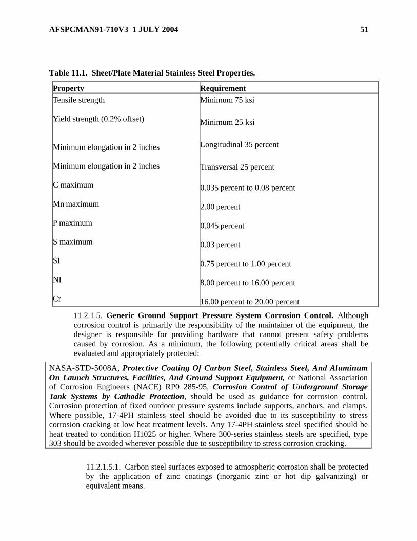
AFSPCMAN91-710V3 1 JULY 2004 51
Table 11.1. Sheet/Plate Material Stainless Steel Properties.
Property Requirement
Tensile strength
Yield strength (0.2% offset)
Minimum elongation in 2 inches
Minimum elongation in 2 inches
C maximum
Mn maximum
P maximum
S maximum
SI
NI
Cr
Minimum 75 ksi
Minimum 25 ksi
Longitudinal 35 percent
Transversal 25 percent
0.035 percent to 0.08 percent
2.00 percent
0.045 percent
0.03 percent
0.75 percent to 1.00 percent
8.00 percent to 16.00 percent
16.00 percent to 20.00 percent
11.2.1.5. Generic Ground Support Pressure System Corrosion Control. Although
corrosion control is primarily the responsibility of the maintainer of the equipment, the
designer is responsible for providing hardware that cannot present safety problems
caused by corrosion. As a minimum, the following potentially critical areas shall be
evaluated and appropriately protected:
NASA-STD-5008A, Protective Coating Of Carbon Steel, Stainless Steel, And Aluminum
On Launch Structures, Facilities, And Ground Support Equipment, or National Association
of Corrosion Engineers (NACE) RP0 285-95, Corrosion Control of Underground Storage
Tank Systems by Cathodic Protection, should be used as guidance for corrosion control.
Corrosion protection of fixed outdoor pressure systems include supports, anchors, and clamps.
Where possible, 17-4PH stainless steel should be avoided due to its susceptibility to stress
corrosion cracking at low heat treatment levels. Any 17-4PH stainless steel specified should be
heat treated to condition H1025 or higher. Where 300-series stainless steels are specified, type
303 should be avoided wherever possible due to susceptibility to stress corrosion cracking.
11.2.1.5.1. Carbon steel surfaces exposed to atmospheric corrosion shall be protected
by the application of zinc coatings (inorganic zinc or hot dip galvanizing) or
equivalent means.

52 AFSPCMAN91-710V3 1 JULY 2004
11.2.1.5.2. Stainless steel surfaces exposed to rocket engine exhaust impingement or
acid deposits from solid rocket motor exhaust shall be coated with inhibitive
polyamide epoxy primer and aliphatic polyurethane topcoat in accordance with
NASA-STD-5008, Protective Coating of Carbon Steel, Stainless Steel, and
Aluminum on Launch Structures.
Nitrile, rubber-based, aluminum-pigmented coating (AR-7) is no longer recommended for
coating stainless steel surfaces because it has a high volatile organic compound content and
is generally unavailable through commercial suppliers.
11.2.1.5.3. Exterior stainless steel surfaces exposed to hypergolic propellant shall be
coated with inhibitive polyamide epoxy primer and aliphatic polyurethane topcoat in
accordance with NASA-STD-5008.
11.2.1.5.4. Underground vessels and piping shall be coated with a coal-tar, epoxy
coating (or equivalent) and galvanically protected.
11.2.1.5.5. All underground systems shall be cathodically protected and designed so
that periodic checks of the protection can be obtained.
11.2.1.5.6. Dissimilar metals shall be protected through mutual isolation.
11.2.1.5.7. All underground metallic systems shall be protected against corrosion by
cathodic protection. Cathodic protection systems (sacrificial or DC power) shall be
designed so that a periodic check of the system can be obtained.
11.2.1.6. Generic Ground Support Pressure System Contamination Control:
11.2.1.6.1. To avoid a hazardous failure, adequate levels of contamination control
shall be established by relating the cleanliness requirements to the actual needs and
nature of the system and components.
KSC-C-123, Surface Cleanliness of Fluid Systems, Specifications for or T.O. 42C-11,
Cleaning and Inspection Procedures for Ballistic Missile Systems, should be used as guidance
in relating cleanliness requirements to the actual needs and nature of the system and
components.
11.2.1.6.2. Materials and fluids used in the design shall be selected to reduce
internally generated contamination caused by rate of wear, friction, and fluid
decomposition.
11.2.1.6.3. Systems shall have acceptable contamination tolerance levels. The
tolerance level of the system and/or components shall be based on considerations of
the overall functional requirements and service life.
11.2.1.6.4. The system shall be designed to verify, through sampling, that the lines
and components are clean after flushing and purging of the system.

AFSPCMAN91-710V3 1 JULY 2004 53
11.2.1.6.5. Each component or section of a system shall be cleaned to the appropriate
level before installation. Immediately following cleaning, all components or sections
of a system shall be protected to prevent contamination.
11.2.1.6.6. Equipment designed to be cleaned or recleaned in place without
significant disassembly shall be provided with high point bleeds and low point drains
to facilitate introduction and removal of cleaning fluid.
11.2.1.6.7. Filters shall be installed immediately downstream of all interfaces where
control of particulate matter is critical and at other appropriate points as required to
control particulate migration.
11.2.1.6.8. Filter design shall permit easy servicing and ready accessibility.
11.2.1.7. Generic Ground Support Pressure System Identification and
Marking. All hazardous pressure system components shall be identified as to function,
content, applicable hazard, and, if applicable, direction of flow. The marking and
identification shall be accomplished by some means that cannot cause “stress
concentration” or otherwise reduce the integrity of the system. Minimum identification
and marking requirements are as follows:
11.2.1.7.1. Fixed Pressure Vessels:
11.2.1.7.1.1. Fixed pressure vessels shall be code stamped in accordance with the
ASME Boiler and Pressure Vessel Code, Section VIII, Pressure Vessels, Division
1, Design and Fabrication of Pressure Vessels, or ASME Code, Section VIII,
Division 2, Alternative Rules.
11.2.1.7.1.2. The maximum pressure at which fixed pressure vessels shall be
normally operated and the name of the working fluid shall be painted in a
conspicuous location on the vessel facing the roadway approach, if possible. This
additional labeling shall be legible at a distance of 50 feet under clear daytime
conditions.
11.2.1.7.2. Portable and mobile pressure vessels shall be marked in accordance with
the applicable DOT specifications.
11.2.1.7.3. Individual lengths or fabricated assemblies of pipe and tubing shall be
identified with part number and/or contractor tracking number, pipe or tube size,
schedule number or wall thickness, test pressure, and the date of hydrostatic and/or
pneumatic test. Identification data shall be affixed to fabricated assemblies by means
of an attached stainless steel band or “dog tag” that has been stamped or
electrochemically etched.
11.2.1.7.4. Fixed ground support piping and tubing runs external to regulation and
control panels and consoles shall be identified in accordance with MIL-STD-1247,
Markings, Functions and Hazard Designations of Hose, Pipe, and Tube Lines for
Aircraft, Missile, and Space Systems, or equivalent.
11.2.1.7.5. All RPIE shall be identified in accordance with MIL-STD-101, Color
Code/Pipelines And For Compressed Gas Cylinders or equivalent.

54 AFSPCMAN91-710V3 1 JULY 2004
11.2.1.7.6. Shutoff and metering valves, pressure relief valves, regulators, gauges,
quick disconnect ground half couplings, and filters shall have the following
information permanently attached to the body by stamping, engraving, tagging, or
other means:
11.2.1.7.6.1. Manufacturer and/or contractor name.
11.2.1.7.6.2. Manufacturer part number.
11.2.1.7.6.3. Applicable design pressure rating.
11.2.1.7.6.4. Service media.
11.2.1.7.6.5. Month and year of most recent calibration for gauges and
transducers.
11.2.1.7.6.6. Flow direction arrow, if applicable.
11.2.1.7.6.7. System reference designation for the component, such as CV1,
CV2.
11.2.1.7.6.8. Unique serial number.
11.2.1.7.7. All manual pressure system regulation and control panels and consoles
shall be clearly marked with a flow schematic, operating parameters, and component
identification.
11.2.1.7.8. The system shall be designed or marked to prevent incorrect installation
of filters.
11.2.1.7.9. Flexible hoses shall be provided with an identification tag that is
permanently and legibly marked with the following information:
11.2.1.7.9.1. Manufacturer name.
11.2.1.7.9.2. Manufacturer and/or contractor part number.
11.2.1.7.9.3. Hose size.
11.2.1.7.9.4. Maximum allowable working pressure (MAWP) or manufacturer
rated working pressure.
11.2.1.7.9.5. Service media.
11.2.1.7.9.6. Month and year of most recent hydrostatic test and test pressure.
11.2.1.7.9.7. System reference designation for the hose, such as FH1, FH2.
11.2.1.7.9.8. Unique serial number.
11.2.1.7.10. An identification tag that is permanently and legibly marked with the
month and year of the most recent set pressure calibration shall be attached to the
relief valve.
11.2.1.8. Generic Ground Support Pressure System Bonding and Grounding. All
pressure systems shall be properly bonded and grounded to provide the following:
KSC-STD-E-0012, Bonding and Grounding, and NFPA 77, Recommended Practices on Static
Electricity, shall be used for guidance.

AFSPCMAN91-710V3 1 JULY 2004 55
11.2.1.8.1. Any single joint measurement shall exhibit a DC resistance of 10
milliohms or less.
11.2.1.8.2. DC resistance from any point in the piping and tubing system to the
nearest earth electrode ground plate shall be 100 milliohms or less.
11.2.1.8.3. A low-impedance path to earth shall be provided for electrical currents
resulting from lightning discharges or electrical power system faults to minimize
abnormal voltage rises that might injure personnel or damage equipment.
11.2.1.8.4. A discharge path shall be provided between distribution piping and tubing
and earth to prevent the buildup of static electricity.
11.2.1.8.5. For flammable or combustible commodities, piping and tubing shall be
bonded to ground at the end termination and at intervals of not more than 100 feet.
11.2.1.8.6. Non-flammable and non-combustible pressure system piping and tubing
shall be bonded to ground at the end terminations and at intervals of not more than
300 feet.
11.2.1.8.7. Flanged joints are acceptable if the flanges are stainless steel or the
flanged areas in contact with the bolt heads and washers are clean and bright. In
addition, the bolts and nuts shall be equipped with serrated or spring washers to
maintain tightness.
11.2.1.8.8. Tubing sections joined with fittings that seat metal-to-metal are
considered adequately bonded.
11.2.1.8.9. All mobile equipment shall be equipped for connection to bonding and
grounding stations at fixed facility transfer apron areas.
11.2.1.8.10. Grounds shall be provided for propellant loading systems (flight
propulsion systems or ground propellant tanks) to allow for common grounding and
bonding during propellant transfer operations. Loading systems include portable
vessels and units.
11.2.1.8.11. The use of interconnecting dissimilar ground metals that could lead to
increased resistance due to galvanic corrosion over a relatively short time period shall
be avoided.
11.2.1.9. Generic Ground Support Pressure System Physical Arrangement and
Human Factors. Pressure systems shall be designed to provide adequate accessibility,
clearance, and operating safety.
MIL-STD-1472 or the equivalent should be used as guidance in designing pressure system
operating consoles.
11.2.1.9.1. Hypergolic system design shall take into consideration the limitations
imposed on individuals dressed in Self-Contained Atmospheric Protective Ensemble
(SCAPE) suits or Propellant Handlers Ensemble (PHE).

56 AFSPCMAN91-710V3 1 JULY 2004
11.2.1.9.2. All components and piping shall be located so they are readily accessible
for maintenance, inspection, and calibration. All piping shall be located to preclude a
hazard to personnel (tripping or head injury).
11.2.1.9.3. Tubing shall be located and protected so that damage cannot occur due to
being stepped on, used as handholds, or by manipulation of tools during maintenance.
11.2.1.9.4. Pressure lines shall clear all structures, components, and other lines by not
less than 1/4 inch under the most adverse conditions of service to ensure that abrasive
chafing does not occur.
11.2.1.9.5. Piping, tubing, and other components shall be routed or located to provide
protection from other operational hazards, including moveable equipment. Where
such exposure is unavoidable, safeguards that minimize the effects of such exposure
shall be incorporated in the design.
11.2.1.9.6. Maximum spacing shall be provided between oxidizer and fuel lines to
preclude mixing and combustion. A minimum of 24 inches shall be provided.
11.2.1.9.7. Pipes containing liquids shall not be attached or secured to electrical lines
or conduit.
11.2.1.9.8. A 2-inch space shall be maintained between electrical conduits and
pressure lines.
11.2.1.9.9. Vent outlets shall be located far enough away from incompatible
propellant systems and incompatible materials to ensure that no contact is made
during vent operations.
11.2.1.9.10. System connections for incompatible propellants shall be keyed, sized,
or located so that it is physically impossible to interconnect them.
11.2.1.9.11. Safety relief valves and burst diaphragms shall be located so that their
discharge is directed away from personnel or safety critical equipment to prevent
injury to personnel or damage to safety critical equipment. If this requirement cannot
be met, safety valves and burst diaphragms shall be equipped with deflection devices.
Consideration shall be given to minimizing the noise hazard of high pressure venting.
11.2.1.9.12. Vent lines for flammable and combustible vapors, toxic gases, and gas
streams that may be contaminated with toxic vapors shall be extended away from
work areas to prevent accidental ignition of vapors and/or injury to personnel.
11.2.1.9.13. Pipe routing shall not block personnel egress routes.
11.2.1.9.14. Pressure systems shall be designed so that the operator is not required to
leave the operating control station to monitor the hazard level of that system.
11.2.1.9.15. Valves carrying hazardous liquids shall not be located overhead in the
area of an operating station.
11.2.1.9.16. Manually operated liquid valves shall be located to permit operation
from the side or above to prevent spillage of service fluid on the operator due to leak
or failure of the valve seals.

AFSPCMAN91-710V3 1 JULY 2004 57
11.2.1.9.17. For systems with failure modes that could result in a time-critical
emergency, provision shall be made for automatic switching to a safe mode of
operation. Caution and warning signals shall be provided for these time-critical
functions.
11.2.1.9.18. Pressure systems shall be designed so that removal and replacement of
tubing can be accomplished with minimal removal of other system components.
11.2.1.9.19. Systems shall be designed with accessibility to perform end-to-end static
ground system checks.
11.2.1.9.20. Pipes containing hazardous liquids shall be routed in a positive slope,
downgrade angle to prevent the accumulation of trapped liquid fluids and allow
draining of the lines.
11.2.1.9.21. Where possible, pipes carrying hazardous liquids shall be mounted so
that the liquid cannot be trapped in internal cavities when it is drained.
11.2.1.9.22. High pressure lines and components shall be protected from damage due
to leakage, servicing, or other operational hazards created by other systems.
11.2.1.9.23. Redundant legs (branches) of a safety pressure system shall be
physically separated and protected so that a single event such as damage, fire, or an
explosion cannot cause both redundant legs to fail.
11.2.1.9.24. Components shall be located and lines routed to minimize the risk of
ignition should a leak or rupture occur.
11.2.1.9.25. Pressure lines shall not be installed inside conduit, large pipe, or tubing
for protective support. EXCEPTION: Lines may be enclosed in protective conduit,
pipes, or tubing when routed under roadways, obstructions, and through thick walls.
11.2.1.9.26. System components such as a hand regulator and gauge that are closely
related shall be arranged to allow operation and surveillance from a common point.
11.2.2. Ground Support Pressure System Hardware Design Requirements:
11.2.2.1. All systems components such as valves, relief devices, regulators, flexible
hoses, pipe line sections, pressure indicating devices, flowmeters, and fittings shall be
subjected to a hydrostatic test of 1.5 times the system maximum operating pressure
(MOP)/MAWP. Where hydrostatic testing is not desirable, a pneumatic test at 1.25 times
the MOP/MAWP may be performed as an alternative test with Range Safety approval.
11.2.2.2. Systems shall be designed to ensure separation of fuels and oxidizers to prevent
their mixing during inadvertent during operations.
11.2.2.3. All calibration adjustments shall be designed so that the setting, position, or
adjustment cannot be inadvertently altered.
11.2.2.4. Permanently Installed Pressure Vessels:
11.2.2.4.1. All permanently installed pressure vessels shall be designed, constructed,
tested, certified, and code stamped in accordance with the ASME Code, Section VIII,
Division 1 or Division 2.

58 AFSPCMAN91-710V3 1 JULY 2004
11.2.2.4.2. All ASME code stamped vessels shall be registered with the National
Board of Boiler and Pressure Vessel inspectors.
11.2.2.4.3. The following additional design, fabrication, and inspection requirements
shall also be met:
11.2.2.4.3.1. Pressure vessels shall be designed with an opening for inspection
purposes.
11.2.2.4.3.2. Pressure retaining welds, including all shell, head nozzle, and
nozzle-to-head or shell welds, shall be inspected using volumetric and surface
NDE techniques.
11.2.2.4.3.3. At a minimum, all attachment welds such as supports, lugs, pads,
and nameplates shall be inspected using surface NDE techniques.
11.2.2.4.3.4. Welded attachments such as stiffening rings or supports shall be
welded with a continuous weld bead.
11.2.2.4.3.5. Welded and bolted attachments such as piping, gussets, ladders, and
platforms to the pressure vessel should be minimized and the design shall be
approved by Range Safety.
11.2.2.4.3.6. External and internal surfaces of vessels shall be free of crevices
and other areas that can trap moisture or contaminants.
11.2.2.4.3.7. All attachments shall be positioned so that no attachment weld will
overlap any category A or B weld as defined by ASME Code, Section VIII,
Division 1 or Division 2.
11.2.2.4.3.8. SA514, SA517, or other alloys with substantially the same
properties as T-1 steel shall not be used for pressure vessels that are fabricated by
welding.
11.2.2.4.4. Fixed pressure vessels exposed to the atmosphere and wind shall be
designed to withstand the maximum expected external loading with a minimum of 2
psig external pressure load as determined by analysis. The analysis shall be conducted
in accordance with ASCE Standard 7-98, Minimum Design Loads for Buildings and
Other Structures, and L.P. Zick, “Stresses in Large Cylindrical Pressure Vessels on
Two Saddle Supports", Pressure Vessel and Piping: Design and Analysis, A Decade
of Progress, Volume 2, published by ASME in 1972.
An additional, good, but non-mandatory, reference is ASME Boiler and Pressure Vessel Code,
Section VII, Division 1, Appendix G, Suggested Good Practice Regarding Piping Reactions
and Design of Supports and Attachments.
11.2.2.4.5. Pressure vessel saddle supports shall be designed in accordance with
ASME Boiler and Pressure Vessel Code, Section VIII, Division 1, Pressure Vessel
Rules, Appendix G, sanctioned guidelines, such as those developed by L.P. Zick, or a
detailed (finite element) analysis shall be performed.

AFSPCMAN91-710V3 1 JULY 2004 59
11.2.2.4.6. Consideration shall be given to anchor bolt design capability for hold
down in the event of a deluge water filled bay (buoyant force of vessel), if applicable.
11.2.2.4.7. One of the two supports of a fixed vessel shall be capable of providing for
expansion and contraction of the vessel.
11.2.2.4.8. All underground hazardous waste tanks and ancillary piping shall comply
with the requirements in 40 CFR 264.193, Containment and Detection of Releases,
and 40 CFR 280, Technical Standards and Corrective Action Requirements for
Owners and Operators of Underground Storage Tanks, and shall have secondary
containment systems with leak detection capability.
11.2.2.4.9. Vessel installation design shall meet range-peculiar conditions such as
severe wind and seismic loads.
11.2.2.4.10. Vessels, tanks, and systems shall be inventoried and records maintained
in the Eastern and Western Range Pressure System Database Management Program.
11.2.2.4.11. Pressure vessels designed and fabricated according to DOT codes are
not normally specified for permanent installation in high pressure systems. If such
vessels are installed on a permanent basis, the installation shall meet ASME design
requirements or be installed to permit easy access to hydrostat the vessel periodically
in compliance with DOT regulations.
11.2.2.4.12. If DOT vessels are used in portable GSE, maintenance and operating
procedures for periodic hydrostatic tests shall be in accordance with DOT regulations.
11.2.2.4.13. All pressure vessels shall be designed to allow for a minimum 10-
percent ullage space at full-load conditions.
11.2.2.5. Portable or Mobile Pressure Vessels:
11.2.2.5.1. Mobile equipment for public and range highway use shall be designed,
fabricated, inspected, and tested to meet the requirements in 49 CFR, Subpart 6, Parts
1000 through 1199, Surface Transportation Board, Department of Transportation.
A copy of any DOT-approved exemptions shall be provided to Range Safety.
11.2.2.5.2. DOT pressure vessels shall be protected against overpressure in
accordance with 49 CFR.
11.2.2.5.3. DOT pressure vessels used and approved for use in a fixed ground-based
system shall be provided overpressure protection in accordance with ASME code.
11.2.2.6. Ground Support Pressure System Piping. At a minimum, all piping
installations shall be designed in accordance with ANSI/ASME B31.3, Process Piping, in
addition to the following:
11.2.2.6.1. Pipe material shall be in accordance with ASTM A312, Standard
Specifications for Seamless and Welding Austenitic Stainless Steel Pipes, and
ANSI/ASME B36.10M, Welded and Seamless Wrought Steel Pipe.
For piping material, recommended pipe material is seamless cold-drawn, type 304L or type
316L stainless steel.

60 AFSPCMAN91-710V3 1 JULY 2004
11.2.2.6.2. Weld fittings such as tees, crosses, elbows, and reducers shall be of the
butt-weld type in accordance with ANSI/ASME B16.9, Factory Made Wrought Steel
Butt Welding Fittings.
Butt-weld fittings should be constructed of ASTM A403, grade WP-316L or WP-304L material.
11.2.2.6.3. Mechanical joints shall be made of ASTM A182, Forged Or Rolled
Alloy-Steel Pipe Flanges, Forged, F316 butt-weld hubs, ASTM A182 F304 clamp
assemblies, and type 17-4PH teflon-coated seal rings. Where system design dictates
the use of industrial flanged-type mechanical joints, they shall be in accordance with
ANSI/ASME B16.5, Pipe Flanges and Flanged Fittings. Flange serrations shall be
of concentric design. Flange gaskets shall conform to ASME B16.21, Nonmetallic
Flat Gaskets for Pipe Flange, and be compatible with the media.
11.2.2.6.4. Threaded National Pipe (NPT) thread connectors shall not be used in
hazardous pressure systems unless under the following applications and with Range
Safety approval:
11.2.2.6.4.1. NPT connectors may be used for small (1-inch Nominal Pipe Size
or less) connections on selected supply components for 6,000 psig gaseous
nitrogen (GN2) and helium (GHe) metering and letdown stations. Selected
components are sample ports, vent/ blowdown valves, pressure indicators,
thermowells, and pressure regulation sensors.
11.2.2.6.4.2. NPT connectors used for connections that do not require repeated
demating/ mating shall have effective corrosion control applied to the exposed
threads to prevent external corrosion from weakening the high stress points.
11.2.2.6.4.3. All of the selected components installed with NPT connections shall
face away from high traffic areas and be anchored or shielded to mitigate
projectile risk if an NPT connector does fail.
11.2.2.6.4.4. Signs shall be placed in the metering and letdown stations warning
personnel not to step on or grab the pipe or components protruding from the pipe
due to use of NPT connectors in the pressure system.
11.2.2.6.4.5. All maintenance procedures and training shall ensure that personnel
performing visual inspections or other checks shall not walk in front of any NPT-
connected components, but shall inspect/observe the NPT connections from a side
position to prevent exposure to high pressure projectiles.
11.2.2.6.4.6. All connections that require periodic demating/mating for periodic
maintenance purposes (such as relief valve functional testing) shall use MS or
equal straight thread connectors; NPT connectors shall not be used.
11.2.2.6.4.7. Pressure reducing regulators shall be installed in the pipeline using
Graylock or equal fittings; not NPT fittings. These are specifically designed for
large, high-pressure connections.
11.2.2.6.5. Socket welded flanges shall not be used in hazardous pressure system
piping.

AFSPCMAN91-710V3 1 JULY 2004 61
11.2.2.6.6. All piping welds shall be of the full penetration butt-weld type.
11.2.2.6.7. All piping and fitting butt welds used to fabricate hazardous pressure
systems shall be 100 percent visually and radiographically inspected. Accept/reject
criteria shall be in accordance with ANSI/ASME B31.3, Table 341.3.2A or Table
K341.3.2A for pressure systems equal to or greater than 6,000 psi.
11.2.2.6.8. Cryogenic piping systems shall provide for thermal expansion and
contraction without imposing excessive loads on the system.
Offset bends and loops rather than bellows should be used for this purpose wherever possible.
11.2.2.6.9. All welded pipe fabricated in place shall be installed with adequate weld-
repair clearance from buildings and other structures.
An adequate weld-repair clearance from buildings and other structures is typically a minimum
of 6 inches.
11.2.2.6.10. All piping shall be located so that it is not hazardous to working
personnel.
11.2.2.6.11. Cryogenic Pipe Weld Inspection:
11.2.2.6.11.1. All inner pipe welds shall be 100 percent radiographically
inspected.
11.2.2.6.11.2. The accept/reject criteria shall be in accordance with Table
341.3.2A of ANSI/ASME B31.3.
11.2.2.7. Ground Support Pressure System Tubing. Tubing connections can be of a
butt-weld type or by use of precision 37-degree fittings.
If welded, pneumatic distribution tubing should be annealed seamless, stainless steel type
304/316 or 304L/316L per ASTM A264.
11.2.2.7.1. If 37-degree flared end fittings are used, they shall be designed in
accordance with precision type AN, MS, or KSC-GP-425, Engineering Standards,
standards.
The material used to join 37-degree flared end fittings should be type 316 stainless steel.
11.2.2.7.2. If butt-weld fittings are used to join tubing, they shall be designed in
accordance with KSC-GP-425 or equivalent.
The material should be type 304L or 316L stainless steel.

62 AFSPCMAN91-710V3 1 JULY 2004
11.2.2.7.3. All tubing and butt-weld fitting welds shall be 100 percent
radiographically inspected. The accept and reject criteria shall be in accordance with
Table 341.3.2 of ASME B31.3.
11.2.2.7.4. Tubing used with AN or MS fittings shall be flared per MS33584, Tubing
End, Standard Dimensions for Flared, and tubing used with KSC-GP-425 fittings
shall be flared per KSC-GP-425. “Crush” washers are prohibited.
11.2.2.7.5. Since flared tubing is not designed for service above 6,000 psig, Range
Safety approved super pressure tubing shall be used for service above 6,000 psig.
11.2.2.7.6. Fabrication and installation of tubing using KSC-P-425 fittings shall be in
accordance with KSC-SPEC-Z-0008, Flared Tube Assemblies and Installation of
Fittings and Fitting Assemblies, Fabrication and Installation of, Specification for.
11.2.2.7.7. Tube fittings with NPT connectors shall not be used in hazardous pressure
systems.
11.2.2.7.8. The number of mechanical joints in tubing systems shall be kept to a
minimum.
All pressure gauge material that normally contacts the service fluid should be type 316 stainless
steel.
EXCEPTION: Bourdon-tube bleed screws may be constructed of any 300 series stainless steel
11.2.2.7.9. Tubing shall be seamless, stainless steel per ASTM A269, Seamless and
Welded Austenitic Stainless Steel Tubing, or KSC-SPEC-Z-0007, Tubing, Steel
Corrosion Resistance Type 304, 316, Seamless, Annealed, Specification for.
11.2.2.8. Ground Support Pressure System Regulators:
11.2.2.8.1. Regulators shall be sized to accurately display the pressure to be used in
the system.
11.2.2.8.2. Manually operated regulators shall be selected so that overtorquing the
regulator cannot damage soft seats to the extent that seat failure occurs.
11.2.2.8.3. Regulators shall be designed so that a functional failure cannot create a
hazard to personnel.
11.2.2.8.4. Dome loaded pressure regulators shall be designed to withstand a
differential pressure across the diaphragm and/or piston equal to the maximum rated
inlet pressure without damage. A means of venting the dome loading circuit shall be
provided.
11.2.2.8.5. Pressure regulator actuators shall be capable of shutting off the fluid when
the system is at the maximum possible flow and pressure.
11.2.2.8.6. A regulator shall not be used as a safety critical component or be required
to function to prevent a failure that might injure personnel.
11.2.2.8.7. For each stage of regulation, the ratio of upstream-to-downstream
pressure shall not exceed 10:1 for optimum control.

AFSPCMAN91-710V3 1 JULY 2004 63
11.2.2.8.8. Regulators shall be selected so their working pressure falls within the
center 50 percent of the total pressure range if it is susceptible to inaccuracies or
creep at either end of the pressure range.
11.2.2.8.9. Regulator design using uncontained seats shall not be used.
11.2.2.8.10. The use of a sheathed flexible actuator such as push-pull wires and
torque wires for regulator control is prohibited.
11.2.2.8.11. Remote readout pressure transducers are required to monitor hazardous
operations from a remote location.
11.2.2.9. Ground Support Pressure System Valves:
11.2.2.9.1. Both manual and automatic valve actuators shall be operable under
maximum design flow and pressure for complete opening and closing the respective
valve.
11.2.2.9.2. Remotely operated valves shall be designed to be fail-safe if pneumatic or
electric control power is lost.
11.2.2.9.3. Designs using uncontained seats shall not be used.
11.2.2.9.4. Use of metal-to-metal seats without Range Safety concurrence is
prohibited.
11.2.2.9.5. Inlet and outlet isolation valves (shutoff valves) and appropriate
intermediate vent valves shall be provided for shutdown and maintenance.
11.2.2.9.6. Valve stem travel shall be limited by a positive stop at each extreme
position.
11.2.2.9.7. The application or removal of force to the stem positioning device shall
not cause disassembly of the pressure containing structure of the valve.
11.2.2.9.8. Manually operated valves shall be designed so that overtorquing the valve
stem cannot damage soft seats to the extent that seat failure occurs.
11.2.2.9.9. Inlet and outlet isolation valves shall be capable of isolating the maximum
allowable working pressure in both directions without seat failure.
11.2.2.9.10. Fast opening valves that can produce high velocity kinetic effects or
heating effects due to rapid pressurization shall not be used.
11.2.2.9.11. Systems shall have shutoff valves located as close to the supply vessel as
practical and be readily accessible.
11.2.2.9.12. Remotely controlled valves shall provide for remote monitoring of open
and closed positions.
11.2.2.9.13. Local or remote stem position indicators shall sense the position of the
stem directly, not the position of the actuating device.
11.2.2.9.14. For remotely controlled valves, positive indication of actual valve
position shall be displayed at the control station. Indication of valve stem position or
flow measurement is an acceptable indication. Indication of a remote command being
initiated is not a positive indication of valve position.
64 AFSPCMAN91-710V3 1 JULY 2004
11.2.2.9.15. Valves used in flared tubing system applications shall be designed for
panel or other rigid mounting.
11.2.2.9.16. All pressure system valves that are required to be in a closed or open
position during system operation shall be protected against inadvertent actuation by
physical means.
Examples of physical means to protect against inadvertent actuation are mechanical stops, lock
wires, or access control.
11.2.2.9.17. Valves that are not intended to be reversible shall be designed or marked
so that they cannot be connected in a reverse mode.
11.2.2.9.17.1. Check valves shall be provided where back flow of fluids would
create a hazard.
11.2.2.9.17.2. Check valves shall be the spring-loaded type with soft seats.
11.2.2.9.18. The use of sheathed flexible actuators, such as push/pull wires and
cables, for valve control is prohibited.
11.2.2.9.19. All electrical control circuits for remote activation shall be shielded or
otherwise protected from hazardous stray energy.
11.2.2.9.20. Balanced manual valves that use external balancing ports or vents open
to the atmosphere shall not be used.
11.2.2.9.21. Remotely operated flow control valves shall be operated pneumatically,
electrically, or hydraulically and shall be capable of fail-safe operation to either the
open or closed position. Determination of fail-safe mode (the open or closed position)
shall depend on the system characteristics.
11.2.2.10. Ground Support Pressure System Vents, Drains, Low Points, Bleeds, Test
Ports, and Sampling Ports. All pressure and propellant systems shall have a low-point
drain capability unless prohibited by the DOT, as well as a high-point bleed capability
with easy accessibility.
11.2.2.10.1. Pressure and propellant systems shall be designed so that commodities
cannot be trapped in any part of the system without vent capability. EXCEPTION:
Loosening of fittings to vent trapped pressure is allowed when the fluid under
pressure is non-hazardous and only for the purpose of calibrating or replacing
pressure gauges or transducers that are provided with an upstream isolation valve
where the total trapped volume does not exceed 1and 1/2 cubic inches.
11.2.2.10.2. Vent system outlets shall be in a location normally inaccessible to
personnel and shall be conspicuously identified.
11.2.2.10.3. Vent outlets shall be protected against rain intrusion and entry of birds,
insects, and animals.
11.2.2.10.4. Oxidizer and fuel vent outlets to the atmosphere shall be separated
sufficiently to prevent mixing of vented fluids/gases.

AFSPCMAN91-710V3 1 JULY 2004 65
11.2.2.10.5. All vent outlets shall be designed to preclude accumulation of vented
fluid in dangerous concentrations in areas frequented by unprotected personnel or
motor vehicles.
11.2.2.10.6. Vent line supports shall be designed to withstand reaction loads due to
the actuation of safety relief devices in accordance with ANSI/ASME B31.3,
Paragraph 322.6.2.
11.2.2.10.7. Each line venting into a multiple-use vent system shall be protected
against back pressurization by a check valve if the upstream system cannot withstand
the back pressure or where contamination of the upstream system cannot be tolerated.
11.2.2.10.8. Incompatible fluids shall not be discharged into the same vent or drain
system.
11.2.2.10.9. Fuel and oxidizer vent systems shall be equipped with a means of
purging the system with an inert gas to prevent explosive mixtures.
11.2.2.10.10. Vent systems shall be sized to provide minimum back pressures
consistent with required venting flow rates. In no case shall back pressures interfere
with proper operation of relief devices.
11.2.2.10.11. Personnel and critical equipment shall be protected from potential
venting hazards.
11.2.2.10.12. Bleed ports shall be located so that they can be operated with minimal
removal of other components and permit the attachment of a hose to direct the bleed-
off material into a container, away from the positions of the operators.
11.2.2.10.13. Test points shall be provided on pressure systems so that disassembly
for test is not required.
11.2.2.10.14. Test points shall be easily accessible for attachment of ground test
equipment.
11.2.2.10.15. A sampling port shall be provided upstream and downstream of each
regulator in any pneumatic branch line that interfaces with a hypergolic propellant
system to permit periodic sampling and analysis of the medium for contamination.
11.2.2.10.16. Sample ports shall be provided at cryogenic system low points.
11.2.2.10.17. A single pressure gauge shall be provided at some point downstream
either in the pneumatic system or the propellant system to indicate the pressure in the
propellant system.
11.2.2.10.18. Gauge calibration ports shall be designed to limit potential
impingement of contaminated gas on personnel.
11.2.2.10.19. The drain system shall include a sump or basin where the fluid can
safely collect. This sump or basin shall be designed so that it can be easily cleaned
and drainage easily removed.
11.2.2.11. Ground Support Pressure System Indicating Devices:

66 AFSPCMAN91-710V3 1 JULY 2004
11.2.2.11.1. All pressure gauges shall conform to the requirements of ANSI/ASME
B40.1, Gauges, Pressure Indicating Dial Type. EXCEPTION: Pressure gauges that
are part of a cylinder regulator assembly such as those used with cutting, welding, or
other industrial equipment are exempt from these requirements as are gauges
associated with pneumatic controllers, positioners, and other standard process
control equipment.
11.2.2.11.2. A pressure indicating device shall be connected downstream of each
pressure regulator, on each storage system, and on any section of the system where
pressure can be trapped.
11.2.2.11.3. Gauges shall be sized to accurately display the pressure to be used in the
system.
11.2.2.11.4. All pressure gauges shall be equipped with a full diameter pressure
release back that shall be sized for maximum flow without case rupture.
11.2.2.11.5. Gauges shall be securely attached to a panel or other rigid mounting.
11.2.2.11.6. If pressure gauge isolation valves are used, they shall be designed so that
they can be secured in the open position.
Lock wiring is an acceptable means of securing pressure gauge isolation valves in the open
position.
11.2.2.11.7. Gauge installations shall be designed to have a minimum of 1-inch
clearance to allow unrestricted venting in the event the gauge vents. Personnel and
equipment shall be protected from the vent area.
11.2.2.11.8. Gauges shall be selected so that the normal operating pressure falls
between 25 percent and 75 percent of the scale range, except for gauges used in
applications that require a wide range of operating pressure, which shall not exceed
95 percent of scale range of the gauge.
11.2.2.11.9. Remote readout pressure transducers shall be required when it is
necessary to monitor hazardous operations from a remote location.
11.2.2.11.10. Pressure gauges shall be of one-piece, solid-front, metal-case
construction, using an optically clear shatterproof window made of high-impact, non-
cracking plastic, heat-treated glass, or laminated glass.
11.2.2.11.11. Liquid system liquid sensors suitable for indicating the presence or
absence of liquid shall be provided.
Metals that could come in contact with the service medium should be compatible, such as type
304 or 316 stainless steel.
11.2.2.11.12. Liquid system liquid level indicators that contain welded portions
(typically magnetic float type) shall be constructed from stainless steel.
Stainless steels such as type 304L or 316L should be used.

AFSPCMAN91-710V3 1 JULY 2004 67
11.2.2.11.13. For liquid systems, the use of glass-faced or radiation source emitting
liquid level indicators is prohibited. Other prohibited types include capacitance,
conductive, and pressure/density types due to historical operational failures and
continuous maintenance problems.
11.2.2.11.14. Liquid system sight glasses used for liquid level indicators shall be
protected from physical damage.
11.2.2.11.15. As required, pressure gauges shall allow for precision cleaning and
verification of cleanliness by particle analysis and non-volatile residue analysis; for
example, a bourdon tube tip bleeder or equivalent.
11.2.2.11.16. Each pressure-indicating device shall be provided with an isolation
valve and a test connection (test port) between the isolation valve and the pressure-
indicating device. Trapped volume between the isolation valve and the pressure-
indicating device shall have a minimum 1-inch clearance.
11.2.2.11.17. The operating range-of-pressure transducers used for monitoring
pressures during hazardous operations shall not be less than 1.2 and not more than 2.0
times the system MOP.
11.2.2.12. Ground Support Pressure System Flexible Hoses:
11.2.2.12.1. Flexible hoses shall be used only when required for hookup of portable
equipment or to provide for movement between interconnecting fluid lines when no
other feasible means is available.
11.2.2.12.2. Flexible hoses shall consist of a flexible inner pressure carrier tube
(compatible with the service fluid) constructed of elastomeric (typically poly-
tetrafluoroethylene [PTFE] for hypergolic fluid) or corrugated metal (typically 300
series stainless steel) material reinforced by one or more layers of 300 series stainless
steel wire and/or fabric braid.
In applications where stringent permeability and leakage requirements apply, hoses with a metal
inner pressure carrier tube should be used. Where these hoses are used in a highly corrosive
environment, consideration should be given to the use of Hastalloy C-22 in accordance with
ASTM B575 for the inner pressure carrier tube and C-276 material for the reinforcing braid.
11.2.2.12.3. Hoses shall be provided with 300-series stainless steel end fittings of the
coupling nut, 37-degree flared type or with fittings to mate with the appropriately
sized ANSI/ ASME B16.5 flange or KC159 hub. Other end fittings may be used for
unique applications, subject to Range Safety approval.
11.2.2.12.4. Interchanging of flexible hoses used in incompatible service media such
as hypergolics shall be avoided. Permeation is not totally negated by any cleaning
process. Hoses shall be dedicated to a service media.
11.2.2.12.5. Hoses over 2 feet long, pressurized to 150 psig or greater, shall meet the
following restraint requirements:
11.2.2.12.5.1. Flexible hoses shall have safety chains or cables securely attached
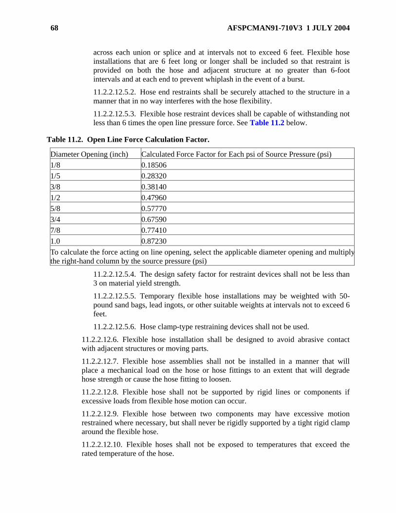
68 AFSPCMAN91-710V3 1 JULY 2004
across each union or splice and at intervals not to exceed 6 feet. Flexible hose
installations that are 6 feet long or longer shall be included so that restraint is
provided on both the hose and adjacent structure at no greater than 6-foot
intervals and at each end to prevent whiplash in the event of a burst.
11.2.2.12.5.2. Hose end restraints shall be securely attached to the structure in a
manner that in no way interferes with the hose flexibility.
11.2.2.12.5.3. Flexible hose restraint devices shall be capable of withstanding not
less than 6 times the open line pressure force. See Table 11.2 below.
Table 11.2. Open Line Force Calculation Factor.
Diameter Opening (inch) Calculated Force Factor for Each psi of Source Pressure (psi)
1/8 0.18506
1/5 0.28320
3/8 0.38140
1/2 0.47960
5/8 0.57770
3/4 0.67590
7/8 0.77410
1.0 0.87230
To calculate the force acting on line opening, select the applicable diameter opening and multiply
the right-hand column by the source pressure (psi)
11.2.2.12.5.4. The design safety factor for restraint devices shall not be less than
3 on material yield strength.
11.2.2.12.5.5. Temporary flexible hose installations may be weighted with 50-
pound sand bags, lead ingots, or other suitable weights at intervals not to exceed 6
feet.
11.2.2.12.5.6. Hose clamp-type restraining devices shall not be used.
11.2.2.12.6. Flexible hose installation shall be designed to avoid abrasive contact
with adjacent structures or moving parts.
11.2.2.12.7. Flexible hose assemblies shall not be installed in a manner that will
place a mechanical load on the hose or hose fittings to an extent that will degrade
hose strength or cause the hose fitting to loosen.
11.2.2.12.8. Flexible hose shall not be supported by rigid lines or components if
excessive loads from flexible hose motion can occur.
11.2.2.12.9. Flexible hose between two components may have excessive motion
restrained where necessary, but shall never be rigidly supported by a tight rigid clamp
around the flexible hose.
11.2.2.12.10. Flexible hoses shall not be exposed to temperatures that exceed the
rated temperature of the hose.

AFSPCMAN91-710V3 1 JULY 2004 69
11.2.2.12.11. Flexible hoses that are permitted to pass close to a heat source shall be
protected with a fireproof boot metal baffle.
11.2.2.12.12. Designs using convoluted, unlined bellows or flexible metal hoses shall
be analyzed to verify premature failure caused by flow-induced vibration is
precluded.
11.2.2.12.13. Acoustic coupling that can intensify the stresses caused by flow-
induced vibration shall be avoided by ensuring that normal fluid flow requirements do
not exceed a velocity of Mach 0.2.
A guidance document for performing the flow-induced vibration analysis is MSFC
20MO2540, Assessment of Flexible Line and Flow-Induced Vibration.
11.2.2.12.14. The bend radius of flexible hoses shall be designed to be no less than
the safe minimum bend radius recommended in authoritative specifications for the
particular hose and in no case less than five times the outside diameter of the hose.
11.2.2.12.15. A means of plugging or capping flexible hoses shall be provided when
the hose is not in use.
11.2.2.12.16. Ground Support Cryogenic System Flexible Hoses:
11.2.2.12.16.1. Flexible hoses shall be used only when required to isolate
vibration and piping movement and for hookup of portable and mobile equipment.
11.2.2.12.16.2. Flexible hoses shall be of the single-wall, double-wall, or double-
wall vacuum-jacketed type.
11.2.2.12.16.3. All convoluted portions of flexible hoses shall be covered with
stainless steel wire braid.
11.2.2.13. Ground Support Pressure System Relief Devices:
11.2.2.13.1. All fixed pressure vessels shall be protected against overpressure by
means of at least one conventional safety relief valve or pilot-operated pressure relief
valve in accordance with ASME Code, Section VIII, Division 1. Rupture disks alone
shall not be used to protect against overpressure.
11.2.2.13.2. A rupture disc may be installed between the pressure relief valve and the
vessel provided that the limitations of ASME Code, Section VIII, Division 1,
Paragraphs UG-127(a)(3)(b) and UG 127(a)(3)(c) or Division 2, Article R-1,
Paragraphs AR-131.4 and AR-131.5 are met.
11.2.2.13.3. Particular care shall be taken to monitor and/or vent the space between
the rupture disc and the relief valve as required. The space between a rupture disc and
a relief valve shall be designed to allow annual testing for leakage and/or
contamination.
11.2.2.13.4. All rupture discs installed in hazardous fluid systems shall be replaced
every two years.

70 AFSPCMAN91-710V3 1 JULY 2004
Providing a screen between the rupture disc and the valve to prevent rupture disc contamination
of the relief valve should be considered.
11.2.2.13.5. Installation of the pressure relief devices shall be in accordance with
ASME Code, Section VIII, Division 1, Paragraph UG-135 or Division 2, Article R-1.
11.2.2.13.6. The flow capacity for all relief devices shall be certified in accordance
with ASME Code, Section VIII, Division 1, Paragraph UG-127, UG-129, UG-131,
and UG-132, as applicable.
11.2.2.13.7. The total relieving capacity of pressure relief devices shall be
determined in accordance with ASME Code, Section VIII, Division 1, Paragraph UG-
133 or Division 2, Paragraph AR150, as applicable. The required relieving capacity
shall be provided by a single valve where possible.
11.2.2.13.8. Pressure relief devices shall be set to operate at a pressure not to exceed
the MAWP of the vessel. [See ASME Code, Section VIII, Division 1, Paragraphs
UG-134(A), UG-134(b), UG-134(c), and UG-134(d)(1)].
11.2.2.13.9. The relieving capacity of the relief valve shall be equal to or greater than
the maximum flow capability of the upstream pressure reducing device or pressure
source and shall prevent the pressure from rising more than 20 percent above the
system MOP or that allowed by ANSI/ASME B31.3, whichever is less.
11.2.2.13.10. Pressure relief valves shall be set to operate at a pressure not to exceed
110 percent of the system MOP or that allowed by ANSI/ASME B31.3, whichever is
less.
11.2.2.13.11. Negative pressure protection shall be provided for vessels not designed
to withstand pressures below 1 atmosphere.
Negative pressure protection may be accomplished by the use of check valves or negative
pressure relief devices.
11.2.2.13.12. Pressure vessel relief devices shall be located so that other components
cannot render them inoperative except as specified in ASME Boiler and Pressure
Vessel Code, Section VIII, Division 1, Paragraphs UG-135(e)(1), UG-135(e)(2), and
Appendix M, Installation and Operations, Paragraphs M-5 and M-6. When a shutoff
valve is allowed in accordance with the ASME Boiler and Pressure Vessel Code, the
valve type shall have provisions for being locked in the open or closed position.
Safety wiring is an acceptable means of locking shutoff valves in the open or closed position.
11.2.2.13.13. The shutoff valve associated with the relief device shall have
permanent marking clearly identifying its position (open or closed).
The body and other pressure containing parts for pressure relief devices should be 300-series
stainless steel. EXCEPTION: DOT cylinders or trailer relief devices may contain parts of brass
or bronze.

AFSPCMAN91-710V3 1 JULY 2004 71
11.2.2.13.14. A pressure relief valve shall be installed downstream of the last GSE
regulator before flight hardware interface and before entering a container and/or black
box purge system.
11.2.2.13.15. All relief valves and piping shall be structurally restrained to eliminate
any thrust effects from transferring moment forces to the vessel nozzles or lines.
11.2.2.13.16. The effects of the discharge from relief devices shall be assessed and
analyzed to ensure that operation of the device cannot be hazardous to personnel or
equipment. Items to be analyzed are thrust loads, noise, impingement of high velocity
gas or entrained particles, toxicity, oxygen enrichment, flammability, and oxygen
deprivation.
11.2.2.13.17. All relief devices shall be vented separately unless the following can be
positively demonstrated:
11.2.2.13.17.1. The creation of a hazardous mixture of gases in the vent system
and the migration of hazardous gases into an unplanned environment is
impossible.
11.2.2.13.17.2. The capacity of the vent system is adequate to prevent a pressure
rise more than 20 percent above MOP or exceed 10 percent of the set pressure of
the valve in accordance with ASME Section VIII, Division 1, Appendix M,
Paragraph M-8. The analysis shall assume that all relief valves connected to the
vent system are open and flowing full capacity.
11.2.2.13.18. Both the inlet and discharge sides of a relief valve shall be
hydrostatically or pneumatically tested. When the discharge side has a lower pressure
rating than the inlet side, they are to be hydrostatically or pneumatically tested
independently. Prior approval of the plan for pneumatic testing shall be obtained from
Range Safety.
11.2.2.13.19. Pressure relief valves shall be tested for proper setting before
installation and annually thereafter.
11.2.2.13.20. Pressure relief devices shall be marked in accordance with ASME
Code Section VIII, Division 1, Paragraphs UG-129, UG-130, UG-131, and UG-132
as applicable.
11.2.2.13.21. A pressure relief valve shall be installed as close as is practical
downstream of each pressure reducing device (regulator, orifice) or downstream of
any source of pressure such as compressors, gas rechargers, and tube bank trailer
whenever any portion of the downstream system cannot withstand the full upstream
pressure. The criteria for “withstand” is that the upstream pressure shall not exceed
the MAWP of any pressure vessel or component downstream of the regulator or
pressure source.
11.2.2.13.22. A three-way valve with dual relief valve is required where continuous
operation of the system is needed during relief valve calibration.

72 AFSPCMAN91-710V3 1 JULY 2004
11.2.2.13.23. Pressure system relief devices shall have no intervening stop valves
between piping being protected and the relief devices or between the relief device and
the point of discharge except as allowed by ANSI/ASME B31.3, Paragraph 322.6.1.
When a shutoff valve is allowed in accordance with the ANSI or ASME code, the
valve shall have provisions for being locked in the open or closed position. The valve
shall have permanent marking clearly identifying its position (open or closed).
Safety wiring is an acceptable means of locking shutoff valves in the open or closed position.
11.2.2.14. Ground Support Pressure System Supports, Anchors, Clamps, and Other
Restraints:
11.2.2.14.1. All piping supports, anchors, hangers, and other restraints shall conform
to the requirements of ANSI/ASME B31.3, Paragraph 321.
11.2.2.14.2. Line Restraints:
11.2.2.14.2.1. Where line restraint is required, anchors, guides, pivots, or
restraints shall be fabricated or purchased and assembled in such a form as to
secure the desired points of piping in relatively fixed positions.
11.2.2.14.2.2. Line restraints shall permit the line to expand and contract freely in
opposite directions away from the anchored or guided point.
11.2.2.14.2.3. Line restraints shall be designed to withstand the thrust, torsional
forces, and load conditions of operation.
11.2.2.14.2.4. Line restraints shall contain the line in case of line failure.
11.2.2.14.2.5. The support shall be capable of withstanding no less than 2 times
the available force as a result of thrust generated from component failure under
pressure.
11.2.2.14.3. All relief valves and attached vent piping shall be designed to withstand
any thrust caused by venting fluids.
11.2.2.14.4. All rigid tubing assemblies shall be supported by rigid structures using
cushioned steel clamps or suitable multiple tube, block-type clamps.
11.2.2.14.5. Tubing supports within consoles or modules shall be spaced according
to the maximum spacing listed in Table 11.3.
Table 11.3. Spacing for Tubing Supports Within Consoles or Modules.
Nominal Tubing Diameter (inches) Maximum Distance Between Tubing Support (inches)
1/8 through 3/8
1/2 through 3/4
1 and over
18
25
30
11.2.2.14.6. Tubing supports between consoles and modules shall be spaced
according to the maximum spacing listed in Table 11.4.

AFSPCMAN91-710V3 1 JULY 2004 73
Table 11.4. Spacing for Tubing Supports Between Consoles or Modules.
Nominal Tubing Diameter (inches) Maximum Distance Between Tubing Support (feet)
1/8 through 3/8
1/2 through 7/8
1 through 2
4
6
9
11.2.2.14.7. Components within a system shall be supported by a firm structure and
not the connecting tubing or piping unless it can be shown by analysis that the tubing
or piping can safely support the component with a safety factor of 3 against yield.
11.2.2.14.8. Hazardous pressure system piping shall be installed with sufficient
flexibility to prevent static or dynamic flow-induced loads and thermal expansion or
contraction from causing excessive stresses to be induced in the system, excessive
bending moments at joints, or undesirable forces or moments at points of connection
to equipment or at anchorage or guide points.
11.2.2.15. Reserved:
11.2.2.16. Ground Support Pressure System Pumps:
11.2.2.16.1. The Standards of the Hydraulic Institute should be used as a guide in
selecting a safe pump.
11.2.2.16.2. Gear pumps shall not be used for high pressure applications involving
flammable and/or hazardous fluids.
11.2.2.16.3. The inlet pressure of hydraulic pumps shall be controlled to prevent
cavitation effects in the pump passage or outlets.
11.2.2.16.4. Hydraulic pumps required to provide emergency power shall not be used
for any other function.
11.2.2.16.5. Hydraulic pressure systems shall have regulators with a pressure
relieving or self-bleeding feature.
11.2.2.16.6. Pumps used in hypergolic propellant systems shall be of the centrifugal
type specifically designed for pumping hypergolic propellants.
11.2.2.17. Ground Support Hydraulic System Hardware:
11.2.2.17.1. General Ground Support Hydraulic System Design:
11.2.2.17.1.1. For all power-generating components, pump pulsations shall be
controlled to a level that does not adversely affect system tubing, components,
and support installation.
11.2.2.17.1.2. When two or more hydraulic actuators are mechanically tied
together, only one lock valve shall be used to hydraulically lock all the actuators.
11.2.2.17.1.3. The ambient operating temperature for hydraulic systems shall not
exceed 275oF for systems using petroleum-based fluids.

74 AFSPCMAN91-710V3 1 JULY 2004
11.2.2.17.1.4. Fluids for systems operating at temperatures higher than 275oF
shall be fire resistant or fireproof for the intended service.
11.2.2.17.1.5. Where system leakage can expose hydraulic fluid to potential
ignition sources, fire resistant or flameproof hydraulic fluid shall be used.
11.2.2.17.1.6. All hydraulic piping installations shall be designed, installed, and
tested in accordance with ANSI/ASME B31.3.
11.2.2.17.1.7. Pressure snubbers shall be used with all hydraulic pressure
transmitters, hydraulic pressure switches, and hydraulic pressure gauges.
EXCEPTION: Pneumatic pressure gauges are excluded from this requirement.
11.2.2.17.1.8. A gauge indicating accumulator gas pressure shall never be used to
indicate equivalent hydraulic pressure.
11.2.2.17.1.9. Pressure system relief devices shall have no intervening stop
valves between piping being protected and the relief devices or between the relief
device and the point of discharge, except as allowed per ANSI/ASME B31.1.
11.2.2.17.1.10. When a shutoff valve is allowed in accordance with the ASME
Code, the valve type shall have provisions for being secured in the open or closed
position.
11.2.2.17.1.11. The shutoff valve shall have permanent marking clearly
identifying it position (open or closed).
11.2.2.17.1.12. Thermal expansion relief valves shall be installed as necessary to
prevent system damage from thermal expansion of hydraulic fluid.
11.2.2.17.1.13. The thermal relief valve setting shall not exceed either the system
test pressure or 120 percent of the system MOP.
11.2.2.17.2. Ground Support Hydraulic System Accumulators and Reservoirs:
11.2.2.17.2.1. Accumulators and reservoirs that are pressurized with gas to
pressures greater than 250 psig shall be designed, constructed, tested, certified,
and code stamped in accordance with ASME Code, Section VIII, Division 1 or
Division 2.
11.2.2.17.2.2. Hydraulic system reservoirs shall be provided with a fluid level
indicator. If a sight glass is used for a liquid level indicator, it shall be properly
protected from physical damage.
11.2.2.17.2.3. Only inert gases shall be used in pressurization accumulators in
systems operating at pressures in excess of 200 psi or temperatures over 160oF
unless adequate fire and explosion resistance is demonstrated.
11.2.2.17.2.4. For a gas-pressurized reservoir, the gas pressure shall be controlled
by an externally nonadjustable pressure regulating device to control the gas
pressure in the reservoir.
11.2.2.17.2.5. Hydraulic systems having reservoir filling caps shall include
design provisions that will automatically vent the reservoir opening.
AFSPCMAN91-710V3 1 JULY 2004 75
11.2.2.18. Ground Support Hypergolic System Hardware. The minimum design
requirements for all fixed, mobile, or portable equipment used to handle hypergolic
propellants (Nitrogen Tetroxide [N2O4 ], Hydrazine [N2H4,] Unsymmetrical
Dimethylhydrazine [UDMH], Aerozine 50 [A-50], Mono Methyl Hydrazine [MMH]) are
described below.
11.2.2.18.1. All fixed hypergolic fuel vessels shall be designed with a minimum
value of 75 psig MAWP.
11.2.2.18.2. All fixed hypergolic oxidizer vessels shall be designed with a minimum
value of 100 psig MAWP.
11.2.2.18.3. Components used in any fuel or oxidizer system shall not be
interchanged after exposure to the respective media.
11.2.2.18.4. Lubricants for hypergolic systems shall be approved compatible
lubricants only.
See KSC-SPEC-Z-0006, Induction Brazing, Aerospace Tubing Fittings, Specification for, for
guidance on compatible lubricants.
11.2.2.18.5. Bi-propellant propellant systems shall have the capability of loading fuel
and oxidizer systems one at a time.
11.2.2.18.6. The minimum design requirements for controlling the migration of
liquid or gas hypergolic propellant into an associated pneumatic system are as
follows:
11.2.2.18.6.1. Each pneumatic branch line that interfaces with a hypergolic
propellant system shall be single fault tolerant to permit positive shutoff of the
pneumatic supply and prevent back flow through the branch. A pressure gauge
shall be provided at some point downstream either in the pneumatic system or the
hypergol system of each check valve to indicate the pressure in the hypergolic
propellant system.
A hand-operated, shutoff valve upstream of a regulator and a spring-loaded, poppet-type check
valve to permit positive shutoff of the pneumatic supply and prevent back flow through the
branch is an acceptable solution.
11.2.2.18.6.2. Each pneumatic branch supply shall interface with only one type of
hypergolic propellant (fuel or oxidizer).
11.2.2.18.6.3. Downstream of the pneumatic pressure regulator, the pneumatic
system shall be identified and marked as a hypergolic system.
11.2.2.18.6.4. All hypergolic vent effluent resulting from routine operations shall
be scrubbed or incinerated, as appropriate, before venting to the atmosphere
through vent stacks.
11.2.2.18.6.5. All scrubber and incinerator designs and qualification tests shall be
reviewed and approved by Range Safety, Bioenvironmental Engineering, and
76 AFSPCMAN91-710V3 1 JULY 2004
Civil Engineering.
11.2.2.18.6.6. Each line venting into a multiple-use vent system shall be
protected against back pressurization by means of a check valve if the upstream
system cannot withstand the back pressure or where contamination of the
upstream system cannot be tolerated.
11.2.2.18.7. Copper, bronze, or other alloys that might form copper oxides shall be
avoided in hydrazine areas. If used, they shall be positively protected by distance,
sealing in a compatible material, or use of a splash guard.
11.2.2.18.8. GSE used to handle propellant systems shall be designed to ensure that
all incompatible fuels and oxidizers are separated so that operations during the
prelaunch phase cannot cause inadvertent mixing of the propellants.
11.2.2.18.9. Downstream of the pneumatic pressure regulator, including the regulator
seat, the pneumatic system shall be constructed of materials that are compatible with
all of the hypergolic propellants serviced by the pneumatic supply.
11.2.2.18.10. The area in close proximity to the hardware containing and/or
transporting hydrazine-based fuels shall be maintained free of surface corrosion and
its associated oxidation byproducts.
11.2.2.18.11. All hypergolic fuel and oxidizer transportation and storage containers
shall have the capability to be grounded.
11.2.2.19. Ground Support Cryogenic System Hardware. The minimum design
requirements for all fixed, mobile, and portable equipment used to handle liquid oxygen
(LO2 or LOX), or liquid hydrogen (LH2), liquid Helium (LHe), liquid nitrogen (LN2)
and their respective vent gases are as follows:
The inner shell and piping in the annular space should be Type 304 or 316 (304L or 316L, if
welded) stainless steel. The outer shell and supports may be stainless steel or carbon steel.
11.2.2.19.1. Cryogenic systems shall be insulated with compatible material or be
vacuum-jacketed to avoid liquefaction of air. Drip pans or other equivalent means
shall be provided under flanges when there exists the possibility of leaking liquefied
air.
11.2.2.19.2. Cryogenic fuel and oxidizer systems shall have the capability of loading
one commodity at a time.
11.2.2.19.3. Vacuum-jacketed systems shall be capable of having the vacuum
verified.
11.2.2.19.4. Purge gas for LH2 and cold gaseous hydrogen (GH2) lines shall be
gaseous helium (GHe). Neither GN2 nor LN2 shall be introduced into any LH2 line
that interfaces with a liquid storage tank cold port.
11.2.2.19.5. Cryogenic systems shall be designed to ensure the separation of fuels
and oxidizers and to prevent inadvertent mixing.
AFSPCMAN91-710V3 1 JULY 2004 77
11.2.2.19.6. Precautions shall be taken to prevent cross mixing of media through
common purge lines by use of check valves to prevent back flow from a system into a
purge distribution manifold.
11.2.2.19.7. Cross connection of GN2 and GHe systems is prohibited.
11.2.2.19.8. All permanently installed cryogenic vessels shall consist of an inner and
an outer shell.
11.2.2.19.9. The annular space between the inner and outer shell shall be insulated
and may be vacuum-jacketed or purged. EXCEPTION: LH2 and LHe vessels shall
be vacuum-jacketed.
11.2.2.19.10. The inner shell shall be designed, constructed, tested, certified, and
code stamped on the exterior of the vessel in compliance with ASME, Section VIII,
Division 1 or Division 2.
11.2.2.19.11. In lieu of the code stamp, a nameplate bearing the required inner shell
data shall be attached to the outer shell.
An additional nameplate marked “duplicate” may be attached to the support structure.
11.2.2.19.12. The outer shell shall be designed for 0.0 pounds per square inch
absolute (psia) internal pressure and 15.0 psia external pressure.
11.2.2.19.13. For nonvacuum-jacketed vessels, the annular space shall be protected
by means of a vacuum breaker.
11.2.2.19.14. Local and remote readout liquid level indicators shall be provided for
LH2 and LO2 storage vessels.
11.2.2.19.15. At a minimum, local readout capability shall be provided for all other
cryogenic storage vessels.
11.2.2.19.16. Cryogenic piping systems shall provide for thermal expansion and
contraction without imposing excessive loads on the system.
11.2.2.19.17. Cryogenic systems shall be designed to ensure icing does not render the
valve inoperable.
11.2.2.19.18. Cryogenic valves with extended stems shall be installed with the
actuator approximately vertical above the valve.
11.2.2.19.19. GH2 shall be vented to the atmosphere through a burner system unless
otherwise agreed to by Range Safety.
11.2.2.19.20. GH2 burner design and testing requirements shall be approved by
Range Safety.
11.2.2.19.21. Pressure vessels shall be designed with an opening for inspection
purposes.
11.2.2.19.22. All inner shell pressure retaining welds including shell, head nozzle,
and nozzle-to-head and shell welds shall be 100 percent inspected by radiographic
and/or ultrasonic volumetric NDE.

78 AFSPCMAN91-710V3 1 JULY 2004
11.2.2.19.23. All inner shell attachment welds for items such as supports, lugs, and
pads shall be 100 percent inspected by liquid penetrant, ultrasonic, magnetic particle,
eddy current, and/ or radiographic surface NDE.
11.2.2.19.24. Welded attachments to the inner vessel such as stiffening rings or
supports shall be continuously welded.
11.2.2.19.25. All attachments to the inner shell shall be positioned so that no
attachment weld overlaps any Category A or B weld as defined in ASME Code,
Section VIII, Division 1, Paragraph UW-3.
11.2.2.19.26. Cryogenic systems shall be provided with readily accessible low-point
drain capability to allow draining of tanks and piping systems. Small volumes
contained in valves, filters, and other containers that will boil off in a short period of
time do not require low-point drain capability.
11.2.2.19.27. Vacuum-jacketed or other types of thermal insulation shall be based on
system heat leak rate and failure mode and effect determination.
11.2.2.19.28. Guidelines for oxygen systems design, material selection, operations,
storage, and transportation can be found in ASTM Manual (MNL) 36, Safe Use of
Oxygen and Oxygen Systems: Guidelines for Oxygen System Design, Materials
Selection, Operations, Storage, and Transportation.
11.2.2.19.29. For failure modes that could result in a time-critical emergency
condition, provisions shall be made for automatic switching to a safe mode of
operation. Caution and warning signals shall be provided for these time-critical
functions.
11.2.2.19.30. Flight propulsion systems and/or propellant tanks and their associated
propellant loading system (including portable vessels and units) shall be commonly
bonded and grounded during propellant transfer operations.
11.2.2.19.31. Titanium and titanium alloys shall not be used where there is possible
exposure to gaseous oxygen (cryogenic boil-off) or liquid oxygen.
11.2.2.20. Ground Support Cryogenic Piping System Joints, Connections, and
Fittings:
11.2.2.20.1. Cryogenic piping design shall be in accordance with ASME B31.3,
Process Piping.
11.2.2.20.2. Joints in piping systems shall be of the butt-weld, flanged, bayonet, or
hub type in accordance with KSC-GP-425, KC159/KC163, or the commercial
equivalent.
11.2.2.20.3. Butt-welded joint designs shall meet the requirements of ANSI/ASME
B16.9.
11.2.2.20.4. Flanged joints shall be either weld neck or lap joint, raised face type
conforming to ANSI/ASME B16.5, Pipe Flanges and Flanged Fittings, and shall be
constructed of forged ASTM A182 304L or 316L material. The use of slip-on flanges
shall be avoided.

AFSPCMAN91-710V3 1 JULY 2004 79
The preferred materials for welded pipe fitting are 304L or 316L stainless steel.
11.2.2.20.5. Flange faces or lap-joint stub end faces shall be concentrically serrated
conforming to MSS-SP-6, Standard Finishes for Contact Faces of Pipe Flanges
and Connecting End Flanges of Valves and Fittings.
11.2.2.20.6. LH2 vent system flanged joints shall be metal-to-metal and shall be seal-
welded unless otherwise approved by Range Safety.
11.2.2.20.7. Flange bolting and studs shall conform to ANSI/ASME B18.2.1, Square
and Hex Bolts and Screw Inch Series recommended dimensions and shall use
ANSI/ASME B1.1, Unified Inch Screw Threads, threads.
11.2.2.20.8. Bolt materials shall be per ASTM A193 or ASTM A320.
11.2.2.20.9. Nuts for flange bolting and studs shall conform to ANSI/ASME B18.2.2,
Square and Hex Nuts (Inch Series), heavy hex type per ASTM A194 or ASTM
ANSI/ASME B1.1 threads.
Type 304 or 316 stainless steel are the preferred materials for nuts and studs used for flange
bolting.
11.2.2.20.10. Pipefittings such as tees, elbows, crosses, reducers, and lap joint stub
ends shall be butt welded only conforming to ANSI/ASME B16.9 in accordance with
ASTM A403.
WP-304L or WP-316L stainless steel are the preferred materials for pipe fittings.
11.2.2.20.11. Bayonet fittings shall be used on vacuum-jacketed lines where butt
welding is not practical and a mechanical joint is required.
11.2.2.20.12. Metal-to-metal couplings shall be the butt-welded types. The gaskets
(not reusable) shall be constructed of stainless steel only. The V-band clamps shall be
constructed of stress-corrosion-resistant material.
11.2.2.20.13. Vacuum-jacketed pipe shall not use bellows in the inner pipe.
Allowance for differential expansion between inner and outer pipe shall be provided
by bellows in the outer pipe.
11.2.2.21. Ground Support Compressed and Breathing Air Systems. The minimum
design requirements for compressed and breathing air systems are as follows:
11.2.2.21.1. Compressed air systems (shop air) operating at 250 lb/in2 or less shall
be designed in accordance with accepted industry standards such as 29 CFR
1910.169, Air Receivers, and ANSI/ASME B19, Safety Standard for Air
Compressor Systems.
11.2.2.21.2. Breathing air systems shall be designed to ensure that the following
requirements are met:
11.2.2.21.2.1. PHEs shall be compatible with the commodities expected to be

80 AFSPCMAN91-710V3 1 JULY 2004
contacted.
11.2.2.21.2.2. PHE has been treated to prevent a static charge buildup.
11.2.2.21.2.3. The breathing air commodity shall meet the requirements of
Federal Specification BB-A-1034B, Air, Compressed for Breathing Purposes,
Grade B or CGA 7.1 Level D for gaseous air. For liquid air, the requirements of
MIL-A-27420, Air, Liquid Breathing, shall be met.
11.2.2.21.2.4. The breathing air piping system and all components shall be
cleaned to Level 200A or cleaner.
11.2.2.21.2.5. The breathing air piping system shall be designed to provide a
positive pad pressure of 10 psig when in standby condition.
11.2.2.21.2.6. Breathing air connect interfaces shall be sized or oriented so that
no interconnection with commodities is possible. Selection of specific quick
disconnects shall be approved by Range Safety.
11.2.2.21.2.7. Air connect interfaces shall be clearly identified with signs or
placards to identify the commodity as “breathing air” or as “shop air (not to be
used as breathing air).”
11.2.3. Ground Support Pressure System Testing:
11.2.3.1. Testing Ground Support Pressure Systems Before Assembly:
11.2.3.1.1. All permanently installed pressure vessels, accumulators, and reservoirs
except DOT vessels shall be hydrostatically tested in accordance with ASME Code,
Section VIII, Division 1, Paragraph UG-99, UG-100 or Division 2, Article T-3 or T-
4, as applicable.
11.2.3.1.2. All other fluid system components such as piping, tubing, flexible hoses,
valves, filters, fittings, and pressure regulators (including pressure gauges,
transducers, or rupture discs) shall be hydrostatically tested to a minimum of 1.5
times the components MAWP for a minimum of 5 minutes.
11.2.3.1.3. Pressure vessels designed to meet DOT specifications shall undergo
qualification and hydrostatic testing in accordance with DOT requirements.
11.2.3.1.4. Hydrostatic or pneumatic testing shall demonstrate that there is no
distortion, damage, or leakage of components at the appropriate test level pressure.
11.2.3.1.5. The following inspections shall be performed after hydrostatic testing:
11.2.3.1.5.1. Mechanical components such as valves, regulators, piping, and
fitting shall be inspected for distortion or other evidence of physical damage.
Damaged components shall be rejected.
11.2.3.1.5.2. After completion of the hydrostatic tests, a functional and leak test
shall be performed at the MAWP of the component.
11.2.3.1.6. Pressure-relief devices, gauges and transducers shall be calibrated before
installation and yearly thereafter.

AFSPCMAN91-710V3 1 JULY 2004 81
11.2.3.1.7. Pneumatic testing to a test pressure of 1.25 times MAWP in lieu of
hydrostatic testing is permissible if hydrostatic testing is impractical, impossible, or
jeopardizes the integrity of the component or system. Prior approval for pneumatic
proof testing at the ranges shall be obtained from Range Safety.
11.2.3.1.8. Certain critical system components may require further testing (mass
spectrometer) in accordance with ASME Boiler and Pressure Vessel Code, Section V,
Nondestructive Examination, Article 10, Appendix IV, Helium Mass Spectrometer
Test – Detector Probe Technique or Appendix V, Helium Mass Spectrometer Test –
Tracer Probe and Hood Techniques.
11.2.3.1.9. All valves used for hypergolic systems shall be tested for both external
and internal leakage at MAWP using an inert gas (helium/nitrogen) consisting of at
least 10 percent helium. The use of argon as a testing medium is prohibited.
11.2.3.1.9.1. No external leakage is allowed (bubble-tight).
11.2.3.1.9.2. Internal leakage of valves shall not exceed limits specified in the
valve performance specification.
11.2.3.1.9.3. Where no valve specification exists, the leak rate shall not exceed 1
x 10-6 cc/sec at standard temperature and pressure.
11.2.3.2. Testing Ground Support Pressure Systems After Assembly:
11.2.3.2.1. Ground Support Pressure System Hydrostatic Tests:
11.2.3.2.1.1. All newly assembled pressure systems shall be hydrostatically tested
to 1.5 times MOP before use. Where this is not possible, Range Safety shall
determine the adequacy of component testing and alternate means of testing the
assembled system. Pneumatic testing at 1.25 time the MOP is acceptable in lieu of
hydrostatic testing at 1.5 times the MOP. Prior approval of the plan for pneumatic
testing shall be obtained from Range Safety.
11.2.3.2.1.2. All cryogenic systems shall be hydrostatically tested to at least 1.25
times system MOP using an inert cryogenic fluid at or below the expected lowest
temperature.
11.2.3.2.1.3. Cryogenic systems that cannot be chilled and hydrostatically tested
with an inert fluid at or below the lowest expected temperature shall require a cold
shock demonstration test, a hazard analysis, and a fracture mechanics safe-life
analysis. The test and analysis methodology is subject to review and approval by
Range Safety.
11.2.3.2.1.4. The hydrostatic test or cold shock/soak test (for at least 1 hour) shall
demonstrate that the system or components shall sustain test pressure level and
temperature gradient without distortion, damage, or leakage.
11.2.3.2.1.5. The following inspections shall be performed on vacuum-jacketed
systems:
11.2.3.2.1.5.1. An examination for cold spots on vacuum jackets. Cold spots
in the outer line shall not be more than 5oC colder than the surrounding area,
except in cases where system heat-leak requirements permit colder
82 AFSPCMAN91-710V3 1 JULY 2004
temperatures, such as around low-point drain valves, relief valves, or other
areas where a direct thermal path is available.
11.2.3.2.1.5.2. Vacuum readings for all vacuum volumes shall be taken and
recorded. These readings shall be taken before, during, and after the test.
11.2.3.2.1.5.3. The vacuum readings after the hydrostatic or cold shock/soak
using a cryogenic fluid shall be taken when the system returns to ambient
temperature.
11.2.3.2.2. Ground Support Pressure System Leak Tests:
11.2.3.2.2.1. For systems with a hazardous fluid, after hydrostatic testing and
before the introduction of propellant, a pneumatic leak test of completely
assembled systems shall be conducted at the system MOP using an inert gas
(helium/nitrogen) consisting of at least 10 percent helium. The use of argon as a
testing medium is prohibited.
11.2.3.2.2.2. After successful completion of the hydrostatic test using a cryogenic
fluid, a pneumatic leak test of the complete system shall be performed at the
system MOP using helium or a mixture of nitrogen with a minimum of 25 percent
helium. There shall be no leakage into the vacuum volume in excess of 1.0E-06
cc/sec. The sensitivity of the instrumentation used to measure leak rate shall be a
minimum of 1 times 1.0E-09 std cm3/sec/ div in accordance with Article 10 of the
ASME Code.
11.2.3.2.2.3. All newly assembled pressure systems, except systems designed,
fabricated, inspected, and tested in accordance with DOT requirements, shall be
leak tested at the system MOP before first use at the ranges.
11.2.3.2.2.4. This test shall be conducted at the ranges unless prior approval from
Range Safety has been obtained.
11.2.3.2.2.5. Minimum test requirements are as follows:
11.2.3.2.2.5.1. The gas or fluid used during the leak test shall be the same as
the system fluid media except those used for hazardous gas systems. A
system-compatible, non-hazardous gas may be used that has a density as near
as possible to the system fluid (for example, helium should be used to leak test
a gaseous hydrogen system).
11.2.3.2.2.5.2. Mechanical connections, gasketed joints, seals, valve bonnets,
and weld seams shall pass a mass spectrometer helium leak check or shall be
visually bubble tight for a minimum of 1 minute when leak tested with MIL-
L-25567, Leak Detection Compound, Oxygen Systems, Type 1 or equivalent
leak test solution.
Alternate methods of leak testing may be approved on a case-by-case basis.
11.2.3.2.2.5.3. Non-hazardous liquid systems may be leak tested using the
normal system service.
AFSPCMAN91-710V3 1 JULY 2004 83
11.2.3.2.3. Ground Support Pressure System Validation and Functional Tests:
11.2.3.2.3.1. All newly assembled pressure systems shall have a system
validation test and a functional test of each component at system MOP before first
operational use at the ranges.
11.2.3.2.3.2. These tests shall be conducted at the ranges unless prior approval
from Range Safety has been obtained.
11.2.3.2.3.3. Minimum test requirements are as follows:
11.2.3.2.3.3.1. Tests shall demonstrate the functional capability of all
components such as valves, regulators, orifices, pumps, and gauges.
11.2.3.2.3.3.2. All operational sequences for the system shall be executed
including emergency shutdown and safing procedures.
11.2.3.2.3.3.3. All shutoff and block valves shall be leak checked downstream
to verify their shutoff capability in the closed position.
11.2.3.2.3.3.4. The intended service fluid shall be used as the test fluid where
practical. Range Safety approved inert service fluid may be used in place of
the service fluid if the intent of the test (equivalent effect on the system) is
demonstrated.
11.2.3.2.3.3.5. Systems shall be tested to verify bonding and grounding.
11.2.3.3. Ground Support Pressure System Periodic Testing and Maintenance:
11.2.3.3.1. Uninstalled flexible hoses shall be hydrostatically proof tested to 1.5
times their MAWP within one year before use. Installed flexible hoses in functional
use shall be hydrostatically tested to 1.5 times their MAWP once a year.
EXCEPTION: This requirement does not apply to flexible hoses that are
permanently installed, located, and operated in an environment that does not exceed
the rated temperature, pressure, and shelf life of the hose.
11.2.3.3.2. At least annually, all permanently installed flexible hoses shall be visually
inspected over their entire length for damaged fittings, broken braid, kinks, flattened
areas, or other evidence of degradation.
11.2.3.3.3. Pressure gauges and transducers shall be calibrated within one year before
use. Pressure gauges and transducers in functional use shall be calibrated once a year.
11.2.3.3.4. Pressure relief valves shall be tested for proper setting and operation once
a year.
11.2.3.4. Testing Modified and Repaired Ground Support Pressure Systems:
11.2.3.4.1. After repairs and/or modifications to existing tankage, piping, and other
system components, tests shall be performed to the same standards, codes, and
requirements for which a new system would be designed, fabricated, and tested.
Minor refurbishment, such as replacement of gaskets, seals, and valve seats that does
not affect structural integrity, does not require a retest.

84 AFSPCMAN91-710V3 1 JULY 2004
11.2.3.4.2. Any pressure system component, including piping, tubing, fittings, or
welds, that has been repaired, modified, or possibly damaged, before having been
hydrostatically or pneumatically tested, shall be retested hydrostatically to 1.5 time
MAWP or pneumatically to 1.25 times MAWP before reuse. Pneumatic testing at the
ranges requires prior approval by Range Safety.
11.2.3.4.3. After hydrostatic testing, modified or repaired systems shall be leak tested
at the system MOP before placing them back in service. This test shall be conducted
at the ranges unless prior approval has been obtained from Range Safety.
11.2.3.4.4. After hydrostatic testing, modified or repaired systems shall be
functionally tested at the system MOP before reuse.
11.2.3.4.5. All system mechanical joints affected in the disconnection, connection, or
replacement of components shall be leak tested at the system MOP before being
placed back in service.
11.2.3.4.6. Gaskets shall not be reused.
11.2.4. Ground Support Pressure System Analysis and Documentation Requirements:
11.2.4.1. Ground Support Pressure System Hazard Analysis:
11.2.4.1.1. As applicable, a hazard analysis, shall be performed on all hazardous
systems hardware and software in accordance with a jointly tailored SSPP. (See
Volume 1, Attachment 2.)
11.2.4.1.2. At a minimum, the hazard analysis shall include the analysis requirements
in AFI 32-4002 and AFMAN 32-4013, Hazardous Materials Emergency Planning
and Response Program, for toxic, reactive, flammable, and explosive fluids and
AFOSHSTD 91-119 and 29 CFR 1910.119 for highly hazardous chemicals, as
applicable.
11.2.4.2. Engineering Assessment, Data, and Analysis Requirements:
11.2.4.2.1. An engineering assessment and analysis shall be performed before the
start of the first recertification period.
11.2.4.2.2. The engineering assessment of the design, fabrication, material, service,
inspection, and testing shall be evaluated against the latest codes, standards,
regulations, and requirements identified in this volume.
11.2.4.2.3. Discrepancies with the latest requirements shall be resolved by repair,
modification, analysis, inspection, or test.
11.2.4.2.4. Design, Fabrication, and Installation Deficiencies. At a minimum, the
following potential design, fabrication, and installation type deficiencies shall be
assessed:
11.2.4.2.4.1. Design deficiencies such as design notches, weld joint design, and
reinforcements.
11.2.4.2.4.2. Material deficiencies such as laminations, laps, seams, cracks,
hardness variations, and notch brittleness.

AFSPCMAN91-710V3 1 JULY 2004 85
11.2.4.2.4.3. Welding deficiencies such as cracks, incomplete fusion, lack of
penetration, overlap, undercut, arc strikes, porosity, slag inclusions, weld spatter,
residual stresses, and distortion.
11.2.4.2.4.4. Installation deficiencies such as fit up, alignment, attachments, and
supports.
11.2.4.2.4.5. Operation and Maintenance Deficiencies. At a minimum, the
following potential operation and maintenance deficiencies shall be assessed:
11.2.4.2.4.5.1. Refurbishment damage.
11.2.4.2.4.5.2. Modification and/or repair deficiencies.
11.2.4.2.4.5.3. Operation beyond allowable limits or improper sequence.
11.2.4.2.4.5.4. Maintenance deficiencies.
11.2.4.3. Inservice Operating, Maintenance, and Inspection Plan. The Range User
responsible for the design of hazardous pressure systems shall prepare an inservice
operating, maintenance, and inspection plan. This plan shall be referred to as the
Inservice Inspection (ISI) Plan. The ISI Plan shall address and provide the following:
Guidance for preparing the ISI Plan can be found in ESMC-TR-88-01, A Guide for
Recertification of Ground Based Pressure Vessels and Liquid Holding Tanks
11.2.4.3.1. Credible failure mechanisms that may cause service-related failures of the
system during its service life shall be analyzed.
11.2.4.3.2. Methods such as “eliminated,” “controlled by design,” “controlled by
procedure,” or “controlled by corrosion protection” used to eliminate and control
these failure mechanisms shall be identified.
Failure mechanisms to be evaluated include corrosion, stress, fatigue, creep, design fabrication,
installation, operation, and maintenance deficiencies.
11.2.4.3.3. Using the results of the above failure mechanism analysis, the following
minimum requirements for an operating, maintenance, and inspection plan shall be
defined:
11.2.4.3.3.1. Operating plans shall address operating constraints such as
maximum pressure, MAWP, MOP, minimum and maximum temperature,
vibration, and maximum cycles.
11.2.4.3.3.2. Maintenance plans shall address corrosion protection, maintenance
schedule, soft-good replacement program, refurbishment, calibration, and other
maintenance requirements.
11.2.4.3.3.3. Inspection plans shall identify the type and frequency of inspections
such as visual, surface, and volumetric NDE required for each vessel and system
to detect the types of failure mechanisms identified in 11.2.4.3.1 above.
11.2.4.3.3.4. Hazardous pressure systems shall be maintained and periodically

86 AFSPCMAN91-710V3 1 JULY 2004
inspected in accordance with the ISI Plan.
11.2.4.3.3.5. Unacceptable findings from the performance of periodic inspections
shall be resolved with Range Safety participation.
11.2.4.4. Ground Support Pressure System Data Requirements. The minimum data
required to certify compliance with the design, analysis, and test requirements of ground
support pressure systems are listed below. The data required shall be incorporated into
the MSPSP or submitted as a separate package when appropriate. Certification data shall
be placed in a certification file to be maintained by the hazardous pressure system
operator. Range Safety shall review and approve this data before first operational use of
new, modified, or repaired hazardous pressure systems at the ranges.
11.2.4.4.1. Ground Support Pressure System General Data Requirements. The
following general ground support equipment data shall be submitted as part of the
MSPSP.
11.2.4.4.1.1. Hazard analysis of hazardous pressure systems in accordance with a
jointly tailored SSPP (Volume 1, Attachment 2).
11.2.4.4.1.2. A compliance checklist of all design, test, analysis, and data
submittal requirements in this volume.
11.2.4.4.1.3. The material compatibility analysis in accordance with the 11.2.1.4
of this chapter.
11.2.4.4.1.4. Inservice operating, maintenance, and inspection plan in accordance
with 11.2.4.3 of this chapter.
11.2.4.4.1.5. Physical and chemical properties and general characteristics of
propellants, test fluids, and gases data.
11.2.4.4.1.6. For hazardous propellants, fluids, and gases, data shall be submitted
in accordance with 3.10.4 and Attachment 1, A1.2.4.7.1.3 of this volume.
11.2.4.4.2. Ground Support Pressure System Design Data
Requirements. Ground support pressure systems design data shall be submitted in
accordance with Attachment 1, A1.2.5.9 of this volume.
11.2.4.4.3. Ground Support Pressure System Component Design Data
Requirements. Ground support pressure systems component design data shall be
submitted in accordance with Attachment 1, A1.2.5.9.3 of this volume.
11.2.4.4.4. Ground Support Pressure System Test Procedures and Reports:
11.2.4.4.4.1. All test plans, test procedures and test reports required in Chapter
11 of this volume shall be submitted to Range Safety for review and approval.
11.2.4.4.4.2. A list and synopsis of all hazardous pressure system operational
procedures to be performed at the ranges shall be provided to Range Safety.
11.3. Ground Support Pressure Systems Certification and Recertification:
11.3.1. Ground Support Pressure Systems Recertification Test Requirements. Testing
requirements for recertification of components and systems are as follows:

AFSPCMAN91-710V3 1 JULY 2004 87
11.3.1.1. Vessels and packaging designed to 49 CFR specifications shall be retested to
DOT requirements.
11.3.1.2. All systems shall be hydrostatically tested at ambient temperatures to 150
percent of the system MOP.
11.3.1.3. Vessels designed to ASME Section VIII, Division 2 that are prohibited from
hydrostatic testing to 150 percent of the MOP shall be hydrostatically tested to 125
percent of system MOP at a minimum.
11.3.1.4. Cryogenic systems shall be retested in accordance with 11.2.3.2 of this volume.
11.3.1.5. 100 percent visual inspection of all joints and connections shall be performed
before and after hydrostatic or pneumatic pressure tests. Parts that indicate a change in
volume, permanent deformation, leakages, or cracks shall be rejected.
11.3.1.6. 100 percent visual inspection of the external surfaces of a vessel and system
and 100 percent of the internal surfaces for vessels shall be performed.
11.3.1.6.1. Any sign of corrosion, dents, or other damages shall be identified and
annotated on permanently maintained recertification documents.
11.3.1.6.2. For corroded areas, the corrosion shall be removed.
11.3.1.6.3. Using ultrasonic testing (UT), the entire surface area affected by
corrosion shall be measured and the remaining wall thickness determined.
11.3.1.6.4. Wall areas that are below the minimum required thickness and other
unacceptable findings shall be fixed before placing the system back into service.
11.3.1.6.5. The susceptibility effects of corrosion such as cracking, delamination, or
intergranular attack should be addressed.
11.3.1.7. All weld joints on vessels and systems with pressure greater than 500 psig or
containing a hazardous fluid shall be 100 percent volumetrically and surface inspected.
11.3.1.7.1. Radiographic examination shall be used to the maximum extent possible.
11.3.1.7.2. UT shall be used if radiographic testing (RT) is determined to be
ineffective.
11.3.1.7.3. Surface and volumetric testing shall be performed after the
hydrostatic/pneumatic pressure test only.
11.3.1.8. All components and systems shall be leak checked and functionally tested.
11.3.1.9. Leaks shall be repaired and components that do not function properly shall be
repaired or replaced before starting the subsequent recertification period.
11.3.2. Ground Support Pressure Systems General Recertification Requirements:
Guidance for performing recertification can be found in ESMC TR-88-01.
11.3.2.1. The recertification period for vessels and systems shall not exceed the shortest
period resulting from or determined by the following criteria:

88 AFSPCMAN91-710V3 1 JULY 2004
11.3.2.1.1. The shortest service life shall be determined based on the system and
components design performance parameters, operational requirements, and inspection
and test results.
11.3.2.1.2. Twenty years for systems and for vessels that can be 100 percent
inspected both internally and externally.
11.3.2.1.3. Ten years for systems and for vessels that cannot be 100 percent
inspected internally but can be 100 percent inspected externally.
11.3.2.1.4. Five years for systems and for vessels that cannot be 100 percent
inspected either internally or externally.
11.3.2.1.5. Manufacturer recommendations.
11.3.2.1.6. Recertification of cryogenic vessels shall be accomplished at a minimum
of every 20 years with an internal inspection every 10 years.
11.3.2.2. All fixed hazardous pressure vessels shall also be recertified when one or more
of the following changes or conditions occur:
11.3.2.2.1. The vessel is planned for service at higher or lower temperatures than
those of the previous certification and/or recertification.
11.3.2.2.2. The vessel was removed from service and deactivated without protection
from environmental effects; for example, a vessel is not stored inside an
environmentally controlled building and does not have a positive internal pressure.
11.3.2.2.3. The vessel was relocated from another installation, agency, or source.
11.3.2.2.4. There is a change of service or commodity, resulting in a new failure or a
change in failure mechanisms.
11.3.2.2.5. The vessel was repaired or modified.
11.3.2.2.6. The vessel has reached the end of its certification or recertification period.
11.3.2.3. Portable or mobile vessels and packaging used for transportation of pressurized
or hazardous commodities shall be designed, maintained, and recertified in accordance
with 49 CFR. If a DOT vessel is installed on a permanent basis, it shall fall under the
recertification requirement for a fixed system.
11.3.2.4. Periodic inspections shall be performed on hazardous pressure systems in
accordance with the ISI Plan (See 11.2.4.3 of this volume). These inspections shall be
performed during the following periods:
11.3.2.4.1. From initial operational use of the vessel and/or system until the vessel
and/or system requires recertification (called certification period).
11.3.2.4.2. Period from first recertification effort until second recertification (called
first recertification period).
11.3.2.4.3. All subsequent recertification periods.
11.3.2.5. The hazardous pressure system operator shall retain all documentation
generated as a result of the recertification effort and place this documentation in the
system certification and recertification file located at the ranges.

AFSPCMAN91-710V3 1 JULY 2004 89
11.3.3. Ground Support Pressure Systems Certification:
11.3.3.1. Ground Support Pressure Systems Certification Files General
Requirements:
11.3.3.1.1. Certification files shall be maintained and updated by the hazardous
pressure system operator. These files shall be located at the Range User facility at the
ranges. Vessels and systems, including mobile and portable systems, that do not have
current certification files may be deactivated and removed from service at the
direction of Range Safety.
11.3.3.1.2. Certification files shall be updated within 90 calendar days of completion
of periodic inspections and tests.
11.3.3.1.3. Updated information shall include any changes to the current certification
files and the following:
11.3.3.1.3.1. Temperature, pressurization history, and pressurizing fluid for both
the tests and operations.
11.3.3.1.3.2. Results of any inspection conducted, including the name of the
inspector, inspection dates, inspection techniques used, location and character of
defects, defect origin, and defect cause.
11.3.3.1.3.3. Maintenance and corrective actions performed from the time of
manufacture throughout operational life, including refurbishment.
11.3.3.1.3.4. Sketches and photographs to show areas of structural damage and
extent of repairs.
11.3.3.1.3.5. Certification and recertification tests performed, including test
conditions and results.
11.3.3.2. Ground Support Pressure System Certification Data:
11.3.3.2.1. The certification file for each hazardous pressure system shall contain all
the data required to justify system certification.
11.3.3.2.2. The data shall include, but not be limited to, the following:
11.3.3.2.2.1. Design calculations for stress, fatigue, and other items that verify
compliance with applicable code requirements such as ASME, ANSI, and DOT.
11.3.3.2.2.2. Structural load analysis for hazardous pressure systems exposed to
severe launch environments such as vibration, shock, and temperature.
11.3.3.2.2.3. In-process fabrication and construction inspection plans and results.
11.3.3.2.2.4. Pressure vessel manufacturer data reports (ASME Form U-1 or
Form U-1A).
11.3.3.2.2.5. Specification drawings and documents for all components.
11.3.3.2.2.6. If available, maintenance manuals for all components.
11.3.3.2.2.7. If available, component operating manual.
11.3.3.2.2.8. As required, a cross-sectional assembly drawing of the component

90 AFSPCMAN91-710V3 1 JULY 2004
to assess the safety aspects of the internal elements.
11.3.3.2.2.9. System operating and maintenance plans and procedures.
11.3.3.2.2.10. Certification that welding and weld NDE meet applicable
standards such as ASME and ANSI.
11.3.3.2.2.11. Unique qualification and acceptance test plans and test reports.
11.3.3.2.2.12. Certification documentation showing that vessels are designed,
fabricated, and tested in accordance with ASME Boiler and Pressure Vessel Code,
Section VIII, Division 1/Division 2 or 49 CFR.
11.3.3.2.2.13. Certification that all components, including pipe and tube fittings
have successfully passed a hydrostatic or pneumatic pressure test.
11.3.4. Ground Support Pressure System Analyses. An engineering analysis shall be
performed as follows:
11.3.4.1. A stress analysis of all vessels and piping shall be available for evaluation or
performed to verify that stresses are within allowable limits of current codes, standards,
and regulations as identified in this volume.
11.3.4.2. The number of stress cycles experienced by the vessel during the certification
period shall be determined.
11.3.4.3. Using fracture mechanics analysis, the cyclic limits for vessels with pressures
greater than 2,500 psig, burst-before-leak failure mode, or corrosive and/or toxic fluids
shall be determined.
11.3.4.4. The safe-life analysis shall be performed under the assumption of pre-existing
cracks. This does not imply that cracks are allowed. All unacceptable indications shall be
repaired. The safe-life analysis shall be conducted in accordance with the following
requirements:
11.3.4.4.1. The analysis shall show that the vessel will service at least 4 times the
cycles expected during the recertification period.
11.3.4.4.2. The analysis shall calculate and evaluate the results from the worst
combination of crack sizes (refer to MSFC-STD-1249, Standard NDE Guidelines
and Requirements for Fracture Control Program, for guidance) and locations such
as boss transition area, heat affected area, weld joint, and membrane section within
the vessel.
11.3.4.4.3. The appropriate stress component in the vessel shall be used in the
analysis.
11.3.4.4.4. The initial flaw size used in the safe-life analysis shall be based on either
the hydrostatic test pressure or the detection limits of the appropriate NDE
techniques. Flaw shapes (a2c) ranging from 0.1 to 0.5 shall be considered.
Refer to MSFC-STD-1249 for guidance.
AFSPCMAN91-710V3 1 JULY 2004 91
11.3.4.4.5. Calculated cycles to failure shall be based on the maximum and minimum
operating pressure.
11.3.4.4.6. A liner elastic fracture mechanic parameter (stress-intensity factors) shall
be used to determine critical crack sizes. The most conservative deformation mode
shall be used to determine the appropriate stress-intensity factors (fracture toughness)
as appropriate for the parent, weld, and joint materials.
11.3.4.4.7. Fracture mechanics shall only be used to predict the subcritical crack
propagation life before unstable crack growth.
11.3.4.4.8. The safe-life analysis results shall be reduced by a factor of 4 in
conjunction with assuming the most conservative bounds on material properties and
crack growth data for the vessel environment.
11.3.4.4.9. Failure mode determination shall be in accordance with Attachment 3 of
this volume.
11.3.4.4.10. Vessels subject to stress corrosion (sustained stress) shall show that the
corresponding applied stress intensity during operation is less than the threshold
stress intensity in the intended environment.
11.3.4.4.11. Corrosion allowance and the remaining wall shall be determined based
on MIL-HDBK-729, Corrosion and Corrosion Prevention Metals.

92 AFSPCMAN91-710V3 1 JULY 2004
Chapter 12
FLIGHT HARDWARE PRESSURE SYSTEMS AND PRESSURIZED STRUCTURES
12.1. Flight Hardware Pressure System and Pressurized Structure General
Requirements. Definition Space Launch System Anomaly: Any parameter (pressure,
temperature, voltage, acceleration, etc.) that deviates outside the prescribed or expected range of
values. Any occurrence that represents an unusual, irregular, abnormal, or unexplained departure
from expected results.
12.1.1. Flight Hardware Presssure System and Pressurized Structure General Design
Requirements:
12.1.1.1. The structural design of all pressure vessels and pressurized structures shall use
industry or government standard processes and procedures for manufacture and repair.
12.1.1.2. The design shall provide for access, inspection, service, repair, and
refurbishment..
12.1.1.3. For all reusable pressure vessels and pressurized structures, the design shall
permit these hardware to be maintained in and refurbished to a flightworthy condition. To
be considered flightworthy, repaired or refurbished hardware items shall pass all the
applicable acceptance tests and inspections required for new flight hardware.
12.1.1.4. Repaired and refurbished hardware shall meet the same conditions of
flightworthiness as new hardware.
12.1.2. Flight Hardware Pressure System and Pressurized Structure Fault Tolerance:
12.1.2.1. Airborne hazardous pressure systems shall be designed to be single fault
tolerant against inadvertent actuations that could result in a critical hazard during
prelaunch operations. Structural failure of tubing, piping, and vessels shall not be
considered single failures provided they meet the requirements of this volume.
12.1.2.2. A pressure system shall be dual fault tolerant if the failure of two components
could result in a catastrophic hazard.
12.1.3. Flight Hardware Pressure System Offloading:
12.1.3.1. For contingency safing operations, hazardous pressure systems shall be
designed so that depressurization and drain fittings are accessible and do not create a
personnel or equipment hazard for offloading hazardous fluids at the launch complex.
12.1.3.2. The design goal is to be able to offload these pressure systems at any point after
pressurization or loading, including the ability to offload all systems at the launch pad
without demating of the spacecraft from the launch vehicle or any other disassembly of
vehicle systems.
12.1.3.3. If the Range User and Range Safety decide that depressurizing and/or
offloading the pressure systems of a mated spacecraft is prohibited at the launch pad,
spacecraft offload procedures shall be approved by Range Safety prior to use.
12.1.4. Flight Hardware Pressure System Operations. The requirements for operating
hazardous pressure systems found in Volume 6 of this publication shall be taken into

AFSPCMAN91-710V3 1 JULY 2004 93
consideration in the design and testing of these systems in addition to the general
requirements identified in 12.5 of this chapter.
12.1.5. Flight Hardware Pressure System and Pressurized Structure Analyses:
12.1.5.1. Flight Hardware Pressure System and Pressurized Structure Hazard
Analysis:
12.1.5.1.1. A hazard analysis shall be performed on all hazardous systems hardware
and software (if applicable) in accordance with a jointly tailored SSPP (Volume 1,
Attachment 2).
12.1.5.1.2. Prelaunch and launch hazards shall be analyzed.
12.1.5.2. Flight Hardware Pressure System and Pressurized Structure Functional
Analysis:
12.1.5.2.1. A detailed system functional analysis shall be performed to determine that
the operation, interaction, or sequencing of components shall not lead to damage to
the launch vehicle, payload, or associated ground support equipment.
12.1.5.2.2. The analysis shall identify all possible malfunctions or personnel errors in
the operation of any component that may create conditions leading to an unacceptable
risk to personnel or equipment.
12.1.5.2.3. The analysis shall also evaluate any credible secondary or subsequent
occurrence, failure, or component malfunction that, initiated by a primary failure,
could result in personnel injury.
12.1.5.2.4. .Items identified by the hazard analyses shall be designated safety critical
and shall require the following considerations:
12.1.5.2.4.1. Hazard identification and proposed corrective action.
12.1.5.2.4.2. Design action.
12.1.5.2.4.3. Safety procedures and operating requirements.
12.1.5.2.4.4. Safety supervision.
12.1.5.2.5. Systems analysis data shall show that:
12.1.5.2.5.1. The system provides the capability of maintaining all pressure levels
in a safe condition in the event of the interruption of any process or control
sequence at any time during test or countdown.
12.1.5.2.5.2. Redundant pressure relief devices have mutually independent
pressure escape routes
12.1.5.2.5.3. In systems where pressure regulator failure may result in a critical
hazard to personnel or hardware safety systems, regulation is redundant and,
where passive redundant systems are specified, includes automatic switchover.
12.1.5.2.5.4. When the hazardous effects of safety critical failures or
malfunctions are prevented through the use of redundant components or systems,
all such redundant components or systems shall be operational before the
initiation of irreversible portions of safety critical operations or events.

94 AFSPCMAN91-710V3 1 JULY 2004
12.1.5.3. Flight Hardware Pressure System and Pressurized Structure Stress
12.1.5.3.1. General Requirements:
12.1.5.3.1.1. A detailed and comprehensive stress analysis of each pressure
vessel and pressurized structure shall be conducted under the assumption of no
crack-like flaws in the structure
12.1.5.3.1.2. The analysis shall determine stresses resulting from the combined
effects of internal pressure, ground or flight loads, and thermal gradients.
12.1.5.3.1.3. Both membrane stresses and bending stresses resulting from internal
pressure and external loads shall be calculated to account for the effects of
geometrical discontinuities, design configuration, and structural support
attachments.
12.1.5.3.1.4. Loads shall be combined by using the appropriate design limit or
ultimate safety factors on the individual loads and comparing the results to
material allowables.
12.1.5.3.1.5. Safety factors shall be as determined in 12.2.
12.1.5.3.1.6. Safety factors on external (support) loads shall be as assigned to the
primary structure supporting the pressurized system.
12.1.5.3.2. Metallic Pressure Vessels and Pressurized Structures Stress Analysis:
12.1.5.3.2.1. For metallic pressure vessels and pressurized structures, classical
solutions are acceptable if the design geometries and loading conditions are
simple and the results are sufficiently accurate (as determined by Range Safety) to
warrant their application.
12.1.5.3.2.2. For metallic pressure vessels and pressurized structures, classical
solutions are acceptable if the design geometries and loading conditions are
simple and the results are sufficiently accurate (as determined by Range Safety) to
warrant their application.
12.1.5.3.2.3. As necessary, local structural models shall be constructed to
augment the overall structural model in areas of rapidly varying stresses.
12.1.5.3.2.4. Minimum material gauge as specified in the design drawings shall
be used in calculating stresses.
12.1.5.3.2.5. The allowable material strengths shall reflect the effects of
temperature, thermal cycling and gradients, processing variables, and time
associated with the design environments.
12.1.5.3.2.6. Minimum margins of safety associated with the parent materials,
weldments, and heat-affected zones shall be calculated and tabulated for all
pressure vessels and pressurized structures along with their locations and stress
levels.
12.1.5.3.2.7. The margins of safety shall be positive against the strength and
stiffness requirements of 12.1.7 and 12.1.8.
AFSPCMAN91-710V3 1 JULY 2004 95
12.1.5.3.3. Composite Hardware Stress Analysis:
12.1.5.3.3.1. For composite overwrapped pressure vessels (COPVs) and
pressurized structures made of composite materials, the state-of-the-art
methodology using composite laminate theory shall be used.
12.1.5.3.3.2. Interlamination normal and shear stresses as well as in-plane stress
components shall be calculated.
12.1.5.3.3.3. Effects of ply orientation, stacking sequence, and geometrical
discontinuities shall be accounted for.
12.1.5.4. Flight Hardware Pressure System and Pressurized Structure Fatigue
Analysis. When conventional fatigue analysis is used to demonstrate the fatigue-life of
an unflawed pressure vessel or pressurized structure, nominal values of fatigue-life
characteristics including stress-life (S-N) data, strain-life (Se N) data of the structural
materials shall be used.
12.1.5.4.1. These data shall be taken from reliable sources or other sources approved
by the procuring agency.
Fatigue-like characteristics data are available from reliable sources such as MIL-HDBK-5.
12.1.5.4.2. The analysis shall account for the spectra of expected operating loads,
pressure, and environments.
12.1.5.4.3. Fatigue damage cumulative technique such as Miner's rule is an
acceptable method for handling variable amplitude fatigue cyclic loadings.
12.1.5.5. Flight Hardware Pressure System and Pressurized Structure Safe-Life
Analysis:
12.1.5.5.1. When crack growth safe-life analysis is used to demonstrate the safe-life
of a pressure vessel or a pressurized structure, undetected flaws shall be assumed to
be in the critical locations and in the most unfavorable orientation with respect to the
applied stress and material properties.
12.1.5.5.2. The size of the flaws shall be based on either the appropriate NDE
techniques or defined by the acceptance proof testing.
12.1.5.5.3. If used, both the crack growth safe-life analysis and the proof test flaw
screening logic shall be based on fracture mechanics methodology that has been
submitted to and approved by Range Safety.
12.1.5.5.4. Nominal values of fracture toughness and fatigue crack growth rate data
associated with each alloy, temper, product form, and thermal and chemical
environments shall be used in the safe-life analysis. However, if proof test logic is
used to determine the initial flaw size, an upper bound fracture toughness value shall
be used in determining both the initial flaw size and the critical flaw size at fracture.
12.1.5.5.5. Pressure vessels or pressurized structures that experience sustained
stresses shall also show that the corresponding maximum stress intensity factor

96 AFSPCMAN91-710V3 1 JULY 2004
(Kmax) during sustained load in operation is less than the stress-corrosion cracking
threshold (KISCC) data in the appropriate environment, Kmax < KISCC.
12.1.5.5.6. A Range Safety approved crack growth software package shall be used to
conduct the safe-life analysis.
12.1.5.5.7. Aspect ratio (a/2c) changes shall be accounted for in the analysis.
12.1.5.5.8. Retardation effects on crack growth rates from variable amplitude loading
shall not be considered without approval by the procuring agency.
12.1.5.5.9. Tensile residual stresses shall be included in the analysis.
12.1.5.5.10. The safe-life analysis shall be included in the stress analysis report. In
particular, loading spectra, environments, assumed initial flaw sizes, crack-growth
models, fatigue crack growth rate, and fracture data shall be delineated. A summary
of significant results shall be clearly presented.
12.1.6. Flight Hardware Pressure Vessel and Pressurized Structure Loads, Pressures,
and Environments:
12.1.6.1. The entire anticipated load-pressure-temperature history and associated
environments throughout the service life shall be determined in accordance with specified
mission requirements.
12.1.6.2. At a minimum, the following factors and their statistical variations shall be
considered:
12.1.6.2.1. The environmentally induced loads and pressures.
12.1.6.2.2. The environments acting simultaneously with these loads and pressures
with their proper relationships.
12.1.6.2.3. The frequency of application of these loads, pressures, environments, and
their levels and duration.
12.1.6.3. The frequency of application of these loads, pressures, environments, and their
levels and duration.
12.1.7. Flight Haardware Pressure Vessel and Pressurized Structure Strength
Requirements:
12.1.7.1. All pressure vessels and pressurized structures shall possess sufficient strength
to withstand limit loads and maximum expected operating pressure (MEOP) in the
expected operating environments throughout their respective service lives without
experiencing detrimental deformation.
12.1.7.2. All pressure vessels and pressurized structures shall also withstand ultimate
loads and design burst pressure in the expected operating environments without
experiencing rupture or collapse.
12.1.7.3. Pressure vessels and pressurized structures shall be capable of withstanding
ultimate external loads and ultimate external pressure (destabilizing) without collapse or
rupture when internally pressurized to the minimum anticipated operating pressure.

AFSPCMAN91-710V3 1 JULY 2004 97
12.1.7.4. All pressure vessels and pressurized structures shall sustain proof pressure
without incurring gross yielding or detrimental deformation and shall sustain design burst
pressure without rupture.
12.1.7.5. When proof tests are conducted at temperatures other than design temperatures,
the change in material properties at the proof temperature shall be accounted for in
determining proof pressure.
12.1.7.6. Pressurized structures subject to instability modes of failure shall not collapse
under ultimate loads nor degrade the functioning of any system due to elastic buckling
deformation under limit loads.
12.1.7.7. Evaluation of buckling strength shall consider the combined action of primary
and secondary stresses and their effects on general instability, local or panel instability,
and crippling.
12.1.7.8. Design loads for buckling shall be ultimate loads, except that any load
component that tends to alleviate buckling shall not be increased by the ultimate design
safety factor.
12.1.7.9. Destabilizing pressures shall be increased by the ultimate design factor, but
internal stabilizing pressures shall not be increased unless they reduce structural
capability.
12.1.7.10. The margin of safety shall be positive and shall be determined by analysis or
test at design ultimate and design limit levels, when appropriate, at the temperatures
expected for all critical conditions.
12.1.8. Flight Hardware Pressure Vessel and Pressurized Structure Stiffness
Requirements:
12.1.8.1. Pressure vessels and pressurized structures shall possess adequate stiffness to
preclude detrimental deformation at limit loads and pressures in the expected operating
environments throughout their respective service lives.
12.1.8.2. The stiffness properties of pressure vessels and pressurized structures shall be
such as to prevent all detrimental instabilities of coupled vibration modes, minimize
detrimental effects of the loads and dynamics response that are associated with structural
flexibility, and avoid adverse contact with other vehicle systems.
12.1.9. Flight Hardware Pressure Vessel and Pressurized Structure Thermal
Requirements:
12.1.9.1. Thermal effects, including heating rates, temperatures, thermal gradient,
thermal stresses and deformations, and changes in the physical and mechanical properties
of the material of construction shall be considered in the design of all pressure vessels
and pressurized structures.
12.1.9.2. These effects shall be based on temperature extremes that simulate those
predicted for the operating environment plus a design margin as specified in MIL-STD-
1540, Test Requirements for Space Vehicles, or equivalent.
12.1.10. Physical Arrangement of Flight Hardware Pressure Systems and System
Components:

98 AFSPCMAN91-710V3 1 JULY 2004
12.1.10.1. Flight Hardware Presssure System and System Component General
Requirements:
12.1.10.1.1. The design of hypergolic systems shall take into consideration
limitations imposed on individuals dressed in SCAPE during fill and drain operations.
12.1.10.1.2. Sufficient clearances are needed for the insertion of assembly tools.
12.1.10.1.3. Redundant pressure components and systems shall be separated from
main systems to decrease the chance of total system failure in case of damage, fire, or
malfunction.
12.1.10.1.4. Pressure systems shall be shielded from other systems to protect against
hazards caused by proximity to combustible gases, heat sources, and electrical
equipment.
12.1.10.1.5. Any failure in any such adjacent system shall not result in combustion,
explosion, or release of pressure fluids.
12.1.10.1.6. Safety critical pressure systems shall be designed so that special tools
shall not be required for removal and replacement of components unless it can be
shown that the use of special tools is unavoidable.
12.1.10.2. Flight Hardware Pressure System components and Fixtures:
12.1.10.2.1. Fixtures for safe handling and hoisting with coordinated attachment
points in the system structure shall be provided for equipment that cannot be hand
carried and attached.
12.1.10.2.2. Components shall be designed so that, during the assembly of parts,
sufficient clearance exists to permit assembly of the components without damage to
seals, O-rings, or backup rings where they pass over threaded parts or sharp corners.
12.1.10.2.3. Handling and hoisting loads shall be in accordance with 29 CFR 1910
requirements and Chapter 6 of this volume and Chapter 6 of Volume 6.
12.1.10.2.4. All incompatible propellant system connections shall be designed to be
physically impossible to interconnect.
Incompatible propellant system connections should be keyed, sized, or located so that it is
physically impossible to interconnect them.
12.1.10.2.5. Quick Disconnect Couplings:
The quick disconnect assembly consists of both the ground-half and air-half couplings.
12.1.10.2.5.1. All quick disconnect couplings shall be designed with a factor of
safety of not less than 2.5.
12.1.10.2.5.2. Quick disconnect coupling bodies and appropriate parts shall be
constructed of 304, 304L, 316, or 316L series stainless steel. All parts that contact
the fluid shall be compatible with the fluid.
12.1.10.2.5.3. The quick disconnect ground-half coupling shall withstand being
AFSPCMAN91-710V3 1 JULY 2004 99
dropped from a height of 6 feet on to a metal deck/grating or concrete floor
without leaking or becoming disassembled.
12.1.10.2.5.4. When uncoupled, the quick disconnect shall seal the air-half and
ground-half couplings and shall not permit external leakage. Both halves of the
coupling shall seal under both low and high pressure. In cryogenic systems only,
quick disconnects used in vent coupling assemblies shall allow gaseous cryogenic
flow through the coupling whether connected or disconnected.
12.1.10.2.5.5. When coupled, the quick disconnect shall permit fluid flow in
either direction.
12.1.10.2.5.6. The quick disconnect shall not permit external leakage during any
phase of coupling or uncoupling.
12.1.10.2.5.7. The quick disconnect shall be designed so that coupling and
uncoupling can be performed with simple motions.
12.1.10.2.5.8. The quick disconnect coupling shall contain a positive locking
device that will automatically lock the connection of the coupling halves. It shall
be possible by visual inspection to determine that the quick disconnect is
completely coupled and locked. The quick disconnect shall not have any partially
coupled unlocked position in which the coupling can remain stable and permit
fluid flow.
12.1.10.2.5.9. Special care shall be taken in the quick disconnect design to ensure
that the possibility of inadvertent uncoupling and/or coupling external leakage due
to side and axial loads is minimized.
12.1.10.2.5.10. The quick disconnect shall be designed to couple/uncouple
without imparting adverse loads on the vehicle fluid lines that could cause flight
hardware damage.
12.1.10.2.5.11. Quick disconnects shall be designed to ensure that all
incompatible fuel and oxidizer couplings cannot be inadvertently connected,
causing mixing of propellants.
12.1.10.2.5.12. All quick disconnect ground half couplings shall be identified in
accordance with the requirements of 11.2.1.7.6 of this volume.
12.1.10.3. Flight Hardware Pressure System Tubing and Piping:
12.1.10.3.1. In general, tubing and piping shall be located so that damage cannot
occur due to being stepped on, used as handholds, or by manipulation of tools during
installation.
12.1.10.3.2. Straight tubing and piping runs shall be avoided between two rigid
connection points.
12.1.10.3.3. Where such straight runs are necessary, provisions shall be made for
expansion joints, motion of the units, or similar compensation to ensure that no
excessive strain is applied to the tubing and fittings.

100 AFSPCMAN91-710V3 1 JULY 2004
12.1.10.3.4. Line bends shall be used to ease stresses induced in tubing by alignment
tolerances and vibration.
12.1.10.4. Flight Hardware Pressure System Flexible Hose Requirements:
Guidance for the handling and installation of flexible hoses can be found in KSC specification
80K51846, Flex Hose Handling and Installation Requirements.
12.1.10.4.1. Flexible hoses shall be used only when required to provide movement
between interconnecting fluid lines when no other means are available.
12.1.10.4.2. Flexible hose systems shall be designed to prevent kinking, avoid
abrasive chafing from the restraining device, and avoid abrasive contact with adjacent
structure or moving parts that may cause reduction in strength.
12.1.10.4.3. Flexible hoses shall not be supported by rigid lines or components if
excessive loads from flexible hose motion can occur.
12.1.10.4.4. Flexible hose assemblies shall not be installed in a manner that will
place a mechanical load on the hose or hose fittings to an extent that will degrade
hose strength or cause the hose fitting to loosen.
12.1.10.4.5. Flexible hoses shall be designed such that the bend radius is no less safe
than the minimum bend radius recommended in authoritative specifications for the
particular hose.
12.1.10.4.6. Flexible hoses shall not be exposed to internal temperatures that exceed
the rated temperature of the hose.
12.1.10.4.7. Flexible hoses that Range Safety permits to pass close to a heat source
shall be protected.
12.1.10.4.8. All flexible hoses that are not lined shall be subjected to a flow-induced
vibration analysis.
MSFC 20MO2540 provides guidance for performing flow-induced vibration analysis.
12.1.10.4.9. Flexible hoses shall consist of a flexible inner pressure carrier tube
(compatible with the service fluid) constructed of elastomeric (typically poly-
tetrafluoroethylene [PTFE]) for hypergolic fluid) or corrugated metal (typically 300
series stainless steel) material reinforced by one or more layers of 300 series stainless
steel wire and/or fabric braid.
In applications where stringent permeability and leakage requirements apply, hoses with a metal
inner pressure carrier tube should be used. If these hoses will be used in a highly errosive
environment, consideration should be given to the use of Hastalloy C-22 in accordance with
ASTM B575 for the inner pressure carrier tube and C-276 material for the reinforcing braid.
12.1.10.4.10. Flexible hose restraining devices shall be designed and demonstrated to
contain a force not less than 1.5 times the open line pressure force (see Table 12.1).

AFSPCMAN91-710V3 1 JULY 2004 101
Table 12.1. Open Line Force Calculation Factor.
Diameter Opening (inch) Calculated Force Factor for Each psi of Source Pressure (psi)
1/8 0.18506
1/5 0.28320
3/8 0.38140
1/2 0.47960
5/8 0.57770
3/4 0.67590
7/8 0.77410
Diameter Opening (inch) Calculated Force Factor for Each psi of Source Pressure (psi)
1.0 0.87230
To calculate the force acting on line opening, select the applicable diameter opening and multiply the
right-hand column by the source pressure (psi)
12.1.10.4.10.1. The restraint design safety factor shall not be less than 3 on
material yield strength.
12.1.10.4.10.2. Hose clamp-type restraining devices shall not be used.
12.1.10.4.11. Flexible hose installations shall be designed to produce no stress or
strain in the hard lines or components. Stresses induced because of dimensional
changes caused by pressure or temperature variations or torque forces induced in the
flexible hose shall be included.
12.1.10.5. Flight Hardware Pressure System Valves, Vents, Vent Lines, and Drains:
12.1.10.5.1. Manually operated valves shall be located to permit operation from the
side or above to prevent spillage of “hazardous” service fluid on the operator due to
leak or failure of the valve seals.
12.1.10.5.2. For remotely controlled non-pyrotechnically actuated valves, positive
indication of actual valve position shall be displayed at the control station.
Indication of valve stem position or flow measurement is an acceptable indication. Indication of
an electrical control circuit actuation is not a positive indication of valve position.
12.1.10.5.3. Vent lines for flammable and combustible vapors shall be extended
away from work areas to prevent accidental ignition of vapors and/or injury to
personnel.
12.1.10.5.4. Vent lines for flammable and combustible vapors shall be extended
away from work areas to prevent accidental ignition of vapors and/or injury to
personnel.
12.1.10.5.5. Safety valves and burst diaphragms shall be located so that their
operation cannot cause injury to personnel standing close by or damage to the
installation or equipment, or they shall be equipped with deflection devices to protect
personnel and equipment.

102 AFSPCMAN91-710V3 1 JULY 2004
12.1.10.5.6. Lines, drains, and vents shall be separated or shielded from other high-
energy systems; for example, heat, high voltage, combustible gases, and chemicals.
12.1.10.5.7. Drain and vent lines shall not be connected to any other lines in any way
that could generate a hazardous mixture in the drain/vent line or allow feedback of
hazardous substances to the components being drained or vented.
12.1.10.5.8. When lines are required for draining liquid explosive, flammable liquids
or explosive waste, they shall be free of pockets or low spots so that a positive flow is
achieved at all points in the drain line.
12.1.10.5.9. The slope shall not be less than 1/4 inch per foot at any point on the
drain line.
12.1.10.6. Flight Hardware Pressure System Test Points:
12.1.10.6.1. If required, test points shall be provided so that disassembly for test is
not required.
12.1.10.6.2. The test points shall be easily accessible for attachment of ground test
equipment.
12.1.10.6.3. Common-plug test connectors for pressure and return sections shall be
designed to require positive removal of the pressure connection before unsealing the
return connections.
12.1.10.6.4. Individual pressure and return test connectors shall be designed to
positively prevent inadvertent cross-connections.
12.1.11. Flight Hardware Pressure System and Pressurized Structure Supports and
Clamps:
12.1.11.1. All rigid pipe and tubing assemblies shall be supported by a firm structure to
restrain destructive vibration, shock, and acceleration.
12.1.11.2. Components within a system shall be supported by a firm structure and not the
connecting tubing or piping unless it can be shown by analysis that the tubing or piping
can safely support the component.
12.1.11.3. Pipe and tube accessories such as supports, anchors, and braces shall be
compatible with hypergolic vapors when installed in a hypergolic propellant system.
12.1.11.4. All threaded parts in safety critical components shall be securely locked to
resist uncoupling forces by acceptable safe design methods.
12.1.11.5. Torque for threaded parts in safety critical components shall be specified.
12.1.11.6. Friction-type locking devices shall be avoided in safety critical applications.
12.1.11.7. Star washers and jam nuts shall not be used as locking devices.
12.1.11.8. The design of internally threaded bosses shall preclude the possibility of
damage to the component or the boss threads because of screwing universal fittings to
excessive depths in the bosses.
12.1.11.9. Retainers or snap rings shall not be used in pressure systems where failure of
the ring would allow connection failures or blow-outs caused by internal pressure.

AFSPCMAN91-710V3 1 JULY 2004 103
12.1.11.10. Snubbers shall be used with all bourdon-type pressure transmitters, pressure
switches, and pressure gauges, except air pressure gauges.
12.1.12. Flight Hardware pressure System Bonding and Grounding:
12.1.12.1. Hazardous pressure systems shall be designed so that the flight system being
loaded or unloaded and the ground support loading system can be commonly grounded
and bonded during transfer operations. When the flight system and the ground system are
connected, maximum DC resistance from any flight system tubing or tanks to the nearest
earth electrode plate shall be 100 milliohms or less. See 11.2.1.8.
12.1.12.2. Propellant system components and lines shall be grounded to metallic
structures.
12.1.12.3. All hazardous pressure systems shall be electrically bonded to the flight
vehicle to minimize the DC resistance between the hazardous pressure system and the
flight vehicle.
12.1.13. Flight Hardware Pressure System and Pressurized Structure Material
Compatibility and Selection:
12.1.13.1. Compatibility:
12.1.13.1.1. Materials shall be compatible throughout their intended service life with
the service fluids and the materials used in the construction and installation of
tankage, piping, and components as well as with nonmetallic items such as gaskets,
seals, packing, seats, and lubricants.
12.1.13.1.2. At a minimum, material compatibility shall be determined in regard to
flammability, ignition and combustion, toxicity, and corrosion.
12.1.13.1.3. Materials that could come in contact with fluid from a ruptured or leaky
tank, pipe, or other components that contain hazardous fluids shall be nonflammable
and non-combustible.
12.1.13.1.4. Compatible materials selection shall be obtained from one of the
following sources:
12.1.13.1.4.1. T.O. 00-25-223.
12.1.13.1.4.2. CPIA 394.
12.1.13.1.4.3. MSFC-HDBK-527.
12.1.13.1.4.4. KTI-5210, NASA/KSC Material Selection List for Oxygen and
Air Services.
12.1.13.1.4.5. KTI-5211, NASA/KSC Material Selection List for Reactive Fluid
Service.
12.1.13.1.4.6. KTI-5212, NASA/KSC Material Selection List for Plastic Films,
Foams, and Adhesive Tapes.
12.1.13.1.4.7. MSFC-STD-3029, NASA/MSFC Guidelines for the Selection of
Metallic Materials for Stress Corrosion Cracking Resistance in Sodium
Chloride Environments.
104 AFSPCMAN91-710V3 1 JULY 2004
12.1.13.1.4.8. Other sources and documents approved by Range Safety.
12.1.13.1.5. Compatibility Testing. When compatibility data cannot be obtained from
Range Safety approved source, compatibility tests shall be performed. Test
procedures, pass/fail criteria, and test results shall be submitted to Range Safety for
review and approval.
12.1.13.1.6. Compatibility Analysis. The Range User shall prepare a compatibility
analysis containing the following information:
12.1.13.1.6.1. List of all materials used in system.
12.1.13.1.6.2. Service fluid in contact with each material.
12.1.13.1.6.3. Source document or test results showing material compatibility in
regard to flammability, toxicity, corrosion, and ignition and combustion.
12.1.13.2. Selection:
12.1.13.2.1. Material "A" allowable values shall be used for pressure vessels and
pressurized structures where failure of a single load path would result in loss of
structural integrity.
12.1.13.2.2. For redundant pressurized structures where failure of a structural
element would result in a safe redistribution of applied loads to other load-carrying
members, material "B" allowables may be used.
12.1.13.2.3. The fracture toughness shall be as high as practical within the context of
structural efficiency and fracture resistance.
12.1.13.2.4. For pressure vessels and pressurized structures to be analyzed with
linear elastic fracture mechanics, fracture properties shall be accounted for in material
selection. These properties include fracture toughness; threshold values of stress
intensity under sustained loading; subcritical crack-growth characteristics under
sustained and cyclic loadings; the effects of fabrication and joining processes; the
effects of cleaning agents, dye penetrants, coatings, and proof test fluids; and the
effects of temperature, load spectra, and other environmental conditions.
12.1.13.2.5. Materials that have a low KISCC in the expected operating
environments shall not be used in pressure vessels and pressurized structures unless
adequate protection from the operating environments can be demonstrated by tests
and reviewed and approved by Range Safety.
12.1.13.2.6. If the material has a less than 60 percent of the plane-strain fracture
toughness, KIc under the conditions of its application, it shall be mandatory to show,
by a “worst case” fracture mechanics analysis, that the low threshold stress intensity
factor cannot precipitate premature structural failure.
12.1.14. Flight Hardware Pressure System Contamination and Cleanliness
Requirements:
12.1.14.1. Adequate levels of contamination control shall be established by relating the
cleanliness requirements to the actual needs and nature of the system and components.
12.1.14.2. General contamination control requirements are as follows:

AFSPCMAN91-710V3 1 JULY 2004 105
12.1.14.2.1. Components and systems shall be protected from contaminants by
filtration, sealed modules, clean fluids, and clean environment during assembly,
storage installation, and use.
12.1.14.2.2. Systems shall be designed to allow verification that the lines and
components are clean after flushing and purging the system.
12.1.14.2.3. Systems shall be designed to ensure that contaminants or waste fluids
can be flushed and purged after fill and drain operations.
12.1.15. Flight Hardware Pressure System Components Service Life and Safe-Life:
12.1.15.1. All hazardous pressure system components shall be designed for safe
endurance against hazardous failure modes for not less than 400 percent of the total
number of expected prelaunch cycles.
12.1.15.2. The safe-life for pressure vessels and pressurized structures shall be
established assuming the existence of pre-existing initial flaws or cracks in the vessel and
shall cover the maximum expected operating loads and environments. The safe-life shall
be at least 4 times the specified life for those pressure vessels not accessible for periodic
inspection and repair.
12.1.15.3. For those pressure vessels and pressurized structures that are readily
accessible for periodic inspection and repair, the safe-life, as determined by analysis and
test, shall be at least four times the interval between scheduled inspection and/or
refurbishment.
12.1.15.4. All pressure vessels and pressurized structures that require periodic
refurbishment to meet safe-life requirements shall be recertified after each refurbishment
by the same techniques and procedures used in the initial certification, unless an
alternative recertification plan has been approved by the procuring agency and Range
Safety.
12.1.16. Flight Hardware Metallic Materials:
12.1.16.1. Selection. Metallic materials shall be selected on the basis of proven
environmental compatibility, material strengths, fracture properties, fatigue-life, and
crack growth characteristics consistent with the overall program requirements.
12.1.16.2. Evaluation. Metallic material evaluation shall be conducted based on the
following considerations:
12.1.16.2.1. The metallic materials selected for design shall be evaluated with respect
to material processing, fabrication methods, manufacturing operations, refurbishment
procedures and processes, and other pertinent factors that affect the resulting strength
and fracture properties of the material in the fabricated as well as the refurbished
configurations.
12.1.16.2.2. The evaluation shall ascertain that the mechanical properties, strengths,
and fracture properties used in design and analyses shall be realized in the actual
hardware and that these properties are compatible with the fluid contents and the
expected operating environments.

106 AFSPCMAN91-710V3 1 JULY 2004
12.1.16.2.3. Materials that are susceptible to stress-corrosion cracking or hydrogen
embrittlement shall be evaluated by performing sustained threshold-stress-intensity
tests when applicable data are not available
12.1.16.3. Characterization. Metallic material characterization shall be based on the
following considerations:
12.1.16.3.1. The allowable mechanical properties, strength and fracture properties of
all metallic materials selected for pressure vessels and pressurized structures shall be
characterized in sufficient detail to permit reliable and high confidence predictions of
their structural performance in the expected operating environments unless these
properties are available from reliable or other sources approved by the procuring
agency.
Strength and fracture properties of metallic materials selected for pressure vessels and pressurized
structures are available from references such as MIL-HDBK-5, ASTM Standards, the Air Force
Damage Tolerant Design Handbook, military specifications, and the Aerospace Structural Metals
Handbook.
12.1.16.3.2. Where material properties are not available, they shall be determined by
test methods approved by the procuring agency.
12.1.16.3.3. The characterization shall produce the following strength and fracture
properties for the parent metals, weldments, and heat-affected zones as a function of
the fluid contents, loading spectra, and the expected operating environments,
including proof test environments, as appropriate:
12.1.16.3.3.1. Tensile yield strength, Fy, and ultimate tensile strength, Fu.
12.1.16.3.3.2. Fracture toughness, KIc, KIe, Kc, KISCC.
12.1.16.3.3.3. Sustained-stress crack-growth data, da/dt versus Kmax.
12.1.16.3.3.4. Fatigue crack growth data, da/dn versus Kl and load ratio, R.
12.1.16.3.4. Proven test procedures shall be used for determining material fracture
properties as required. These procedures shall conform to recognized standards.
Recognized standards include those developed by the ASTM.
12.1.16.3.5. The test specimens and procedures used shall provide valid test data for
the intended application.
12.1.16.3.6. Enough tests shall be conducted so that meaningful nominal values of
fracture toughness and crack growth rate data corresponding to each alloy system,
temper, product form, thermal and chemical environments, and loading spectra can be
established to evaluate compliance with safe-life requirements.
12.1.16.3.7. If the conventional fatigue analysis is to be performed, the stress-life (S-
N) or the strain-life (Se-N) fatigue data shall be generated in accordance with the
standard test methods developed by ASTM.

AFSPCMAN91-710V3 1 JULY 2004 107
12.1.16.4. Fabrication and Process Control:
12.1.16.4.1. Proven processes and procedures for fabrication and repair shall be used
to preclude damage or material degradation during material processing,
manufacturing operations, and refurbishment.
12.1.16.4.2. In particular, the melt process, thermal treatment, welding process,
forming, joining, machining, drilling, grinding, repair and rewelding operations, and
other operations shall be within the state-of-the-art and have been used on currently
approved hardware.
12.1.16.4.3. The fracture toughness, mechanical and physical properties of the parent
materials, weldments and heat-affected zones shall be within established design limits
after exposure to the intended fabrication processes.
12.1.16.4.4. The machining, forming, joining, welding, dimensional stability during
thermal treatments, and through-thickness hardening characteristics of the material
shall be compatible with the fabrication processes to be encountered.
12.1.16.4.5. Fracture control requirements and precautions shall be defined in
applicable drawings and process specifications.
12.1.16.4.6. Detailed fabrication instructions and controls shall be provided to ensure
proper implementation of the fracture control requirements.
12.1.16.4.7. Special precautions shall be exercised throughout the manufacturing
operations to guard against processing damage or other structural degradation. In
addition, procurement requirements and controls shall be implemented to ensure that
suppliers and subcontractors use fracture control procedures and precautions
consistent with the fabrication and inspection processes intended for use during actual
hardware fabrication.
12.1.17. Flight Hardware Pressure Vessel and Pressurized Structure Quality Assurance
Program Requirements:
12.1.17.1. A quality assurance (QA) program shall be established to ensure that the
necessary NDE and acceptance tests are effectively performed to verify that the product
meets the requirements of this publication. The QA program shall be based on a
comprehensive study of the product and engineering requirements, drawings, material
specifications, process specifications, workmanship standards, design review records,
stress analysis, failure mode analysis, safe-life analysis, and the results from development
and qualification tests.
12.1.17.2. The program shall ensure that materials, parts, subassemblies, assemblies, and
all completed and refurbished hardware conform to applicable drawings and process
specifications; that no damage or degradation has occurred during material processing,
fabrication, inspection, acceptance tests, shipping, storage, operational use and
refurbishment; and that defects that could cause failure are detected or evaluated and
corrected.
12.1.17.3. QA program Inspection Plan. At a minimum, the following considerations
shall be included in structuring the quality assurance program:

108 AFSPCMAN91-710V3 1 JULY 2004
12.1.17.3.1. An inspection master plan shall be established before the start of
fabrication.
12.1.17.3.2. The plan shall specify appropriate inspection points and inspection
techniques for use throughout the program, beginning with material procurement and
continuing through fabrication, assembly, acceptance proof test, operation, and
refurbishment, as appropriate.
12.1.17.3.3. In establishing inspection points and inspection techniques,
consideration shall be given to the material characteristics, fabrication processes,
design concepts, structural configuration, and accessibility for inspection of flaw.
12.1.17.3.4. For metallic hardware, the flaw geometries shall encompass defects
commonly encountered, including surface crack at the open surface, corner crack or
through-the-thickness crack at the edge of fastener hole, and surface crack at the root
of intersecting prismatic structural elements.
12.1.17.3.5. Acceptance and rejection standards shall be established for each phase
of inspection and for each type of inspection technique.
12.1.17.3.6. For COPVs and other composite hardware, laminate defects, such as
delamination, fiber breakage, surface cuts, porosity, air bubbles, cracks, dents, and
abrasions, shall be considered.
12.1.17.3.7. All inspections shall be performed by inspectors qualified and certified
in inspection techniques according to the American Society for Nondestructive
Testing recommended practices (SNT-TC-1A) or Range Safety approved equivalent.
12.1.17.3.8. .For COPVs, inspectors shall also be certified to American Society for
Nondestructive Testing (ASNT) Level II (or Range Safety approved equivalent) and
shall be familiar with laminate production processes and composite shell defects.
Inspectors shall be certified to inspect specific types of COPVs using specific
inspection techniques in accordance with ASNT standards.
12.1.17.4. Inspection Techniques. At a minimum, the following considerations shall be
included in determining the appropriate inspection techniques:
12.1.17.4.1. The selected NDE inspection techniques shall have the capability to
determine the size, geometry, location, and orientation of a flaw or defect; to obtain,
where multiple flaws exist, the location of each with respect to the other and the
distance between them; and to differentiate among defect shapes, from tight cracks to
spherical voids.
12.1.17.4.2. Two or more NDE methods shall be used for a part or assembly that
cannot be adequately examined by only one method.
12.1.17.4.3. The flaw detection capability of each selected NDE technique shall be
based on past experience on similar hardware.
12.1.17.4.4. Where this experience is not available or is not sufficiently extensive to
provide reliable results, the capability, under production or operational inspection
conditions, shall be determined experimentally and demonstrated by tests approved

AFSPCMAN91-710V3 1 JULY 2004 109
by the procuring agency on representative material product form, thickness, and
design configuration.
12.1.17.4.5. The flaw detection capability shall be expressed in terms of detectable
crack length, crack depth, and crack area. For COPVs, the detection of laminate
defects, such as delamination, fiber breakage, and air bubbles, shall also be addressed.
12.1.17.4.6. The selected NDE should be capable of detecting allowable initial flaw
size corresponding to a 90 percent probability of detection at a 95 percent confidence
level.
12.1.17.4.7. The most appropriate NDE technique(s) for detecting commonly
encountered flaw types shall be used for all metallic pressure vessels, COPVs,
pressurized structures, and other hardware based on their flaw detection capabilities.
12.1.17.5. Inspection Data. At a minimum, inspection data shall be dispositioned as
follows:
12.1.17.5.1. Inspection data in the form of flaw histories shall be maintained
throughout the life of the pressure vessel or pressurized structure. The inspection data
shall be stored in the system certification file.
12.1.17.5.2. These data shall be periodically reviewed and assessed to evaluate trends
and anomalies associated with the inspection procedures, equipment and personnel,
material characteristics, fabrication processes, design concept, and structural
configuration.
12.1.17.5.3. The result of this assessment shall form the basis of any required
corrective action.
12.1.17.5.4. For suspect COPVs, a Material Review Board (MRB) shall be initiated
to evaluate the NDE results and disposition. The MRB shall consist of the procuring
agency (Range User), the COPV manufacturer, and Range Safety. The MRB shall use
NDE comparison, past experience, additional NDE, and other qualitative and
quantitative methods to determine the acceptability of a suspect vessel. Data collected
from the MRB process shall be input into the inspection database and system
certification file.
12.1.17.6. Acceptance Proof Test:
12.1.17.6.1. All pressure vessels, pressurized structures, and pressure components
shall be proof-pressure tested in accordance with the requirements of 12.2 through
12.5, as applicable, to verify that the hardware has sufficient structural integrity to
sustain the subsequent service loads, pressure, temperatures, and environments.
12.1.17.6.2. For pressure vessels, pressurized structures, and other pressurized
components, the temperature shall be consistent with the critical use temperature; or,
as an alternative, tests may be conducted at an alternate temperature if the test
pressures are suitably adjusted to account for temperature effects on strength and
fracture toughness.
12.1.17.6.3. Proof-test fluids shall be compatible with the structural materials in the
pressure vessels and pressurized structures.

110 AFSPCMAN91-710V3 1 JULY 2004
12.1.17.6.4. Proof test fluids shall not pose a hazard to test personnel.
12.1.17.6.5. If such compatibility data is not available, required testing shall be
conducted to demonstrate that the proposed test fluid does not deteriorate the test
article.
12.1.17.6.6. Accept/reject criteria shall be formulated before the acceptance proof
test.
12.1.17.6.7. Every pressure vessel and pressurezed structure shall not leak, rupture,
or experince gross yielding during acceptance testing.
12.1.18. Flight Hardware Pressure System and Pressurized Structure Operations and
Maintenance:
12.1.18.1. Flight Hardware Pressure System and Pressurized Structure Safe
Operating Limits:
12.1.18.1.1. Safe operating limits shall be established for each pressure vessel and
each pressurized structure based on the appropriate analysis and testing used in its
design and qualification in accordance with 12.2, 12.3, and 12.4.
12.1.18.1.2. These safe operating limits shall be summarized in a format that
provides rapid visibility of the important structural characteristics and capability.
12.1.18.2. Flight Hardware Pressure System and Pressurized Structure Operating
Procedures:
12.1.18.2.1. Operating procedures shall be established for each pressure vessel and
pressurized structure.
12.1.18.2.2. These procedures shall be compatible with the safety requirements and
personnel control requirements at the facility where the operations are conducted.
12.1.18.2.3. Step-by-step directions shall be written with sufficient detail to allow a
qualified technician or mechanic to accomplish the operations.
12.1.18.2.4. Schematics that identify the location and pressure limits of relief valves
and burst discs shall be provided when applicable, and procedures to ensure
compatibility of the pressurizing system with the structural capability of the
pressurized hardware shall be established.
12.1.18.2.5. Before initiating or performing a procedure involving hazardous
operations with pressure systems, practice runs shall be conducted on non-pressurized
systems until the operating procedures are well rehearsed.
12.1.18.2.6. Initial tests shall then be conducted at pressure levels not to exceed 50
percent of the normal operating pressures until operating characteristics can be
established and stabilized.
12.1.18.2.7. Only qualified and trained personnel shall be assigned to work on or
with high pressure systems.
12.1.18.2.8. Warning signs with the hazard(s) identified shall be posted at the
operations facility before pressurization.

AFSPCMAN91-710V3 1 JULY 2004 111
12.1.18.3. Flight Hardware Pressure System and Pressurized Structure Inspection
and Maintenance:
12.1.18.3.1. The results of the appropriate stress and safe-life analyses shall be used
in conjunction with the appropriate results from the structural development and
qualification tests to develop a quantitative approach to inspection and repair.
12.1.18.3.2. Allowable damage limits shall be established for each pressure vessel
and pressurized structure so that the required inspection interval and repair schedule
can be established to maintain hardware to the requirements of this volume.
12.1.18.3.3. NDE technique(s) and inspection procedures to reliably detect defects
and determine flaw size under the condition of use shall be developed for use in the
field and depot levels.
12.1.18.3.4. Procedures shall be established for recording, tracking, and analyzing
operational data as it is accumulated to identify critical areas requiring corrective
actions.
12.1.18.3.5. Analyses shall include prediction of remaining life and reassessment of
required inspection intervals.
12.1.18.4. Flight Hardware Pressure System and Pressurized Structure Repair and
Refurbishment:
12.1.18.4.1. When inspections reveal structural damage or defects exceeding the
permissible levels, the damaged hardware shall be repaired, refurbished, or replaced,
as appropriate.
12.1.18.4.2. All repaired or refurbished hardware shall be recertified after each repair
and refurbishment by the applicable acceptance test procedure for new hardware to
verify their structural integrity and to establish their suitability for continued service.
12.1.18.5. Flight Hardware Pressure System and Pressurized Structure Storage
Requirements:
12.1.18.5.1. When pressure vessels and pressurized structures are put into storage,
they shall be protected against exposure to adverse environments that could cause
corrosion or other forms of material degradation.
12.1.18.5.2. Pressure vessels and pressurized structures shall be protected against
mechanical degradation resulting from scratches, dents, or accidental dropping of the
hardware.
12.1.18.5.3. Induced stresses due to storage fixture constraints shall be minimized by
suitable storage fixture design.
12.1.18.5.4. In the event storage requirements are violated, recertification shall be
required before acceptance for use.
12.1.18.6. Flight Hardware Pressure System and Pressurized Structure
Reactivation:
12.1.18.6.1. Pressure vessels and pressurized structures that are reactivated for use
after an extensive period in either an unknown, unprotected, or unregulated storage

112 AFSPCMAN91-710V3 1 JULY 2004
environment shall be recertified to ascertain their structural integrity and suitability
for continued service before commitment to flight.
12.1.18.6.2. Recertification tests for pressureized hardware shall be in accordance
with the appropriate Recertification Test Requirement. (See 12.2.2.8).
12.1.19. Flight Hardware Pressure System and Pressurized Structure Documentation
Requirements:
12.1.19.1. Inspection, maintenance, and operation records shall be kept and maintained
throughout the life of each pressure vessel and each pressurized structure.
12.1.19.2. At a minimum, the records shall contain the following information:
12.1.19.2.1. Temperature, pressurization history, and pressurizing fluid for both tests
and operations.
12.1.19.2.2. Number of pressurizations experienced as well as number allowed in
safe-life analysis.
12.1.19.2.3. Results of any inspection conducted, including the inspector, inspection
dates, inspection techniques employed, location and character of defects, defect
origin, and cause.
12.1.19.2.4. Storage condition.
12.1.19.2.5. Maintenance and corrective actions performed from manufacturing to
operational use, including refurbishment.
12.1.19.2.6. Sketches and photographs to show areas of structural damage and extent
of repairs.
12.1.19.2.7. Acceptance and recertification tests performed, including test conditions
and results.
12.1.19.2.8. Analyses supporting the repair or modification that may influence future
use capability.
12.2. Flight Hardware pressure Vessel Design, Analysis, and Test Requirements:
12.2.1. Flight Hardware Metallic Pressure Vessel General Design, Analysis, and
Verification Requirements. Two approaches for the design, analysis and verification of
metallic pressure vessels can be selected as shown in Figure 12.1. Selection of the approach
to be used depends on the desired efficiency of design coupled with the level of analysis and
verification testing required
12.2.1.1. Approach A. Approach A in Figure 12.1 shows the steps required for
verification of a metallic pressure vessel designed with a burst factor equal to 1.5 or
greater.
12.2.1.1.1. Based on the results of the failure mode determination, one of two distinct
verification paths shall be satisfied: (1) leak-before-burst (LBB) with leakage of the
contents not creating a condition that could lead to a mishap (such as toxic gas
venting or pressurization of a compartment not capable of the pressure increase), and
(2) brittle failure mode or LBB in which, if allowed to leak, the leak causes a hazard.
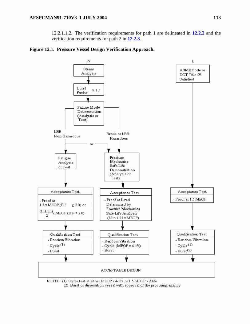
AFSPCMAN91-710V3 1 JULY 2004 113
12.2.1.1.2. The verification requirements for path 1 are delineated in 12.2.2 and the
verification requirements for path 2 in 12.2.3.
Figure 12.1. Pressure Vessel Design Verification Approach.
114 AFSPCMAN91-710V3 1 JULY 2004
12.2.1.2. Approach B. Approach B, Figure 12.1 shows the steps required for
verification of a metallic pressure vessel designed using the ASME Boiler and Pressure
Vessel Code or the DOT Pressure Vessel Codes.
12.2.2. Flight Hardware Metallic Pressure Vessels with Non-Hazardous LBB Failure
Mode:
12.2.2.1. The LBB failure mode shall be demonstrated analytically or by test showing
that an initial surface flaw with a shape (a/2c) ranging from 0.05 to 0.5 will propagate
through the vessel thickness to become a through-the-thickness crack with a length less
than or equal to 10 times the vessel thickness and still be stable at MEOP.
12.2.2.2. Fracture mechanics shall be used if the failure mode is determined by analysis.
12.2.2.3. A pressure vessel that contains non-hazardous fluid and exhibits LBB failure
mode is considered a non-hazardous LBB pressure vessel.
12.2.2.4. Flight Hardware Metallic Pressure Vessels with Non-Hazardous LBB
Failure Mode Factor of Safety Requirements:
12.2.2.4.1. Metallic pressure vessels that satisfy the non-hazardous LBB failure mode
criterion may be designed conventionally, wherein the design factors of safety and
proof test factors are selected on the basis of successful past experience.
12.2.2.4.2. Unless otherwise specified, the minimum burst factor shall be 1.5.
12.2.2.5. Flight Hardware Metallic Pressure Vessels with Non-Hazardous LBB
Failure Mode Fatigue-Life Demonstration:
12.2.2.5.1. After completion of the stress analysis conducted in accordance with the
requirements of 12.1.5.3, conventional fatigue-life analysis shall be performed, as
appropriate, on the unflawed structure to ascertain that the pressure vessel, acted upon
by the spectra of operating loads, pressures, and environments meets the life
requirements.
12.2.2.5.2. A life factor of 4 shall be used in the analysis..
12.2.2.5.3. Testing of unflawed specimens to demonstrate fatigue-life of a specific
pressure vessel together with stress analysis is an acceptable alternative to fatigue test
of the vessel.
12.2.2.5.4. Fatigue-life requirements are considered demonstrated when the unflawed
specimens that represent critical areas such as membrane section, weld joints, heat-
affected zone, and boss transition section successfully sustain the limit loads and
MEOP in the expected operating environments for the specified test duration without
rupture.
12.2.2.5.5. The required test duration is 4 times the specified service life.
12.2.2.6. Flight Hardware Metallic Pressure Vessels with Non-Hazardous LBB
Failure Mode Qualification Test Requirements:
12.2.2.6.1. Qualification tests shall be conducted on flight quality hardware to
demonstrate structural adequacy of the design.

AFSPCMAN91-710V3 1 JULY 2004 115
12.2.2.6.2. The test fixtures, support structures, and methods of environmental
application shall not induce erroneous test conditions.
12.2.2.6.3. The types of instrumentation and their locations in qualification tests shall
be based on the results of the stress analysis of 12.1.5.3.
12.2.2.6.4. The instrumentation shall provide sufficient data to ensure proper
application of the accept/reject criteria, which shall be established before test.
12.2.2.6.5. The sequences, combinations, levels, and duration of loads, pressure, and
environments shall demonstrate that design requirements have been met.
12.2.2.6.6. Qualification testing shall include random vibration testing and pressure
testing. The following delineates the required tests:
12.2.2.6.6.1. Random Vibration Testing. Random vibration qualification testing
shall be performed in accordance with the requirements of MIL-STD-1540 or
equivalent unless it can be shown that the vibration requirement is enveloped by
other qualification testing performed.
12.2.2.6.6.2. Pressure Testing. Required qualification pressure testing levels are
shown in Table 12.2. Requirements for application of external loads in
combination with internal pressures during testing shall be evaluated based on the
relative magnitude and/or destabilizing effect of stresses due to the external load.
If limit-combined tensile stresses are enveloped by test pressure stresses, the
application of external loads shall not be required. If the application of external
loads is required, the load shall be cycled to limit for 4 times the predicted number
of operating cycles of the most severe design condition (for example,
destabilizing load with constant minimum internal pressure or maximum additive
load with a constant maximum expected operating pressure). Qualification test
procedures shall be approved by the procuring agency and the appropriate range
approval authority.

116 AFSPCMAN91-710V3 1 JULY 2004
Table 12.2. Qualification Pressure Test Requirements.
Test Item No Yield after No Burst at (1)
Vessel #1(2) Burst Factor x MEOP
Vessel #2 Cycle at 1.5 x MEOP for 2x predicted
number of service life. (50 cycles
minimum)
or
Cycle at 1.0 x MEOP for 4x predicted
number of service life. (50 cycles
minimum)
Burst Factor x MEOP
(1) Unless otherwise specified, after demonstrating no burst at the design burst pressure
test level, increase pressure to actual burst of vessel. Record actual burst pressure.
(2) Test may be deleted at discretion of the Range User.
12.2.2.7. Flight Hardware Metallic Pressure Vessels with Non-Hazardous LBB
Failure Mode Acceptance Test Requirements. Every pressurized system element shall
be proof tested to verify that the materials, manufacturing processes, and workmanship
meet design specifications and that the hardware is suitable for flight.
12.2.2.7.1. Acceptance tests shall be conducted on every pressure system element
before commitment to flight. Accept/reject criteria shall be formulated before tests.
12.2.2.7.2. The test fixtures and support structures shall be designed to permit
application of all test loads without jeopardizing the flightworthiness of the test
article.
12.2.2.7.3. At a minimum, the following are required:
12.2.2.7.3.1. Nondestructive Inspection. A complete inspection by the selected
nondestructive inspection (NDE) technique(s) shall be performed before the
proof-pressure test to establish the initial condition of the hardware.
12.2.2.7.3.2. Proof-Pressure Test. Every pressure vessel shall be proof-pressure
tested to verify that the materials, manufacturing processes, and workmanship
meet design specifications and that the hardware is suitable for flight. The proof
pressure shall be equal to:
for burst factor less than 2.0 or 1.5 x (MEOP) for burst factor equal or greater than 2.0.

AFSPCMAN91-710V3 1 JULY 2004 117
12.2.2.8. Flight Hardware Metallic Pressure Vessels with Non-Hazardous LBB
Failure Mode Recertification Test Requirements. All refurbished pressure system
elements shall be recertified after each refurbishment by the acceptance test requirements
for new hardware to verify their structural integrity and to establish their suitability for
continued service before commitment to flight. Pressure vessels that have exceeded the
approved storage environment (temperature, humidity, time, and others) shall also be
recertified by the acceptance test requirements for new hardware.
12.2.2.9. Special Provisions. For one-of-a-kind applications, a proof test of each flight
unit to a minimum of 1.5 times MEOP and a conventional fatigue analysis showing a
minimum of 10 design lifetimes may be used in lieu of the required pressure testing as
defined in 12.2.2.6. The implementation of this option needs prior approval by the
procuring agency and the appropriate range approval authority.
12.2.3. Flight Hardware Metallic Pressure Vessels with Brittle Fracture or Hazardous
LBB Failure Mode:
12.2.3.1. Flight Hardware Metallic Pressure Vessels with Brittle Fracture or
Hazardous LBB Failure Mode Factor of Safety Requirements:
12.2.3.1.1. Safe-life design methodology based on fracture mechanics techniques
shall be used to establish the appropriate design factor of safety and the associated
proof factor for metallic pressure vessels that exhibit brittle fracture or hazardous
LBB failure mode.
12.2.3.1.2. The loading spectra, material strengths, fracture toughness, and flaw
growth rates of the parent material and weldments, test program requirements, stress
levels, and the compatibility of the structural materials with the thermal and chemical
environments expected in service shall be taken into consideration.
12.2.3.1.3. Nominal values of fracture toughness and flaw growth rate data
corresponding to each alloy system, temper, and product form shall be used along
with a life factor of 4 on specified service life in establishing the design factor of
safety and the associated proof factor.
12.2.3.1.4. Unless otherwise specified, the minimum burst factor shall be 1.5.
12.2.3.2. Flight Hardware Metallic Pressure Vessels with Brittle Fracture or
Hazardous LBB Failure Mode Safe-Life Demonstration Requirements:
12.2.3.2.1. After completion of the stress analysis conducted in accordance with the
requirements of 12.1.5.3, a safe-life analysis of each pressure vessel covering the
maximum expected operating loads and environments shall be performed under the
assumption of pre-existing initial flaws or cracks in the vessel.
12.2.3.2.2. The analysis shall show that the metallic pressure vessel with flaws
placed in the most unfavorable orientation with respect to the applied stress and
material properties, of sizes defined by the acceptance proof test or NDE and acted
upon by the spectra of expected operating loads and environments, meets the safe-life
requirements of 12.1.15.
12.2.3.2.3. Nominal values of fracture toughness and flaw growth rate data
associated with each alloy system, temper, product form, thermal and chemical

118 AFSPCMAN91-710V3 1 JULY 2004
environments, and loading spectra shall be used along with a life factor of 4 on
specified service life in all safe-life analyses.
12.2.3.2.4. Pressure vessels that experience sustained stress shall also show that the
corresponding applied stress intensity (KI) during operation is less than KISCC in the
appropriate environment.
12.2.3.2.5. Testing of metallic pressure vessels under fracture control in lieu of safe-
life analysis is an acceptable alternative, provided that, in addition to following a
quality assurance program (12.1.17) for each flight article, a qualification test
program is implemented on pre-flawed specimens representative of the structure
design.
12.2.3.2.6. These flaws shall not be less than the flaw sizes established by the
acceptance proof test or the selected NDE method(s).
12.2.3.2.7. Safe-life requirements of 12.1.15 are considered demonstrated when the
pre-flawed test specimens successfully sustain the limit loads and pressure cycles in
the expected operating environments without rupture.
12.2.3.2.8. A life factor of 4 on specified service life shall be applied in the safe-life
demonstration testing.
12.2.3.2.9. A report that documents the fracture mechanics safe-life analysis or safe-
life testing shall be prepared to delineate the following:
12.2.3.2.9.1. Fracture mechanics data (fracture toughness and fatigue crack
growth rates).
12.2.3.2.9.2. Loading spectrum and environments.
12.2.3.2.9.3. Initial flaw sizes.
12.2.3.2.9.4. Analysis assumptions and rationales.
12.2.3.2.9.5. Calculation methodology.
12.2.3.2.9.6. Summary of significant results.
12.2.3.2.9.7. References.
12.2.3.2.10. This report shall be closely coordinated with the stress analysis report
and shall be periodically revised and updated during the life of the program.
12.2.3.3. Flight Hardware Metallic Pressure Vessels with Brittle Fracture or
Hazardous LBB Failure Mode Qualification Test Requirements. Qualification
testing shall meet requirements of 12.2.2.6.
12.2.3.4. Flight Hardware Metallic Pressure Vessels with Brittle Fracture or
Hazardous LBB Failure Mode Acceptance Test Requirements. Acceptance test
requirements for pressure vessels that exhibit brittle fracture or hazardous LBB failure
mode are identical to those with ductile fracture failure mode as defined in 12.2.2.7
except that the test level shall be that defined by the fracture mechanics analysis. Surface
and volume NDE shall be performed before and after proof test on the weld joints as a
minimum. Cryo-proof acceptance test procedures may be required to adequately verify
AFSPCMAN91-710V3 1 JULY 2004 119
initial flaw size. The pressure vessel shall not rupture or leak at the acceptance test
pressure.
12.2.3.5. Flight Hardware Metallic Pressure Vessels with Brittle Fracture or
Hazardous LBB Failure Mode Recertification Test Requirements. Recertification
testing shall meet the requirements of 12.2.2.8.
12.2.3.6. Flight Hardware Metallic Pressure Vessels with Brittle Fracture or
Hazardous LBB Failure Mode Special Provisions. For one-of-a-kind applications, a
proof test of each flight unit to a minimum of 1.5 times MEOP and a conventional fatigue
analysis showing a minimum of 10 design lifetimes may be used in lieu of the required
pressure testing as defined in 12.2.2.6 for qualification. The implementation of this option
needs prior approval by Range Safety.
12.2.4. Flight Hardware Metallic Pressure Vessels Designed Using ASME Boiler and
Pressure Vessel Code. Metallic pressure vessels may be designed and manufactured per the
rules of the ASME Boiler and Pressure Vessel Code, Section VIII, Divisions 1 or 2.
12.2.4.1. Flight Hardware Metallic Pressure Vessels Designed Using ASME Boiler
and Pressure Vessel Code Qualification Test Requirements. Qualification testing
shall meet the requirements of 12.2.2.6.
12.2.4.2. Flight Hardware Metallic Pressure Vessels Designed Using ASME Boiler
and Pressure Vessel Code Acceptance Test Requirements:
12.2.4.2.1. A proof test shall be performed as specified in ASME Code pressure test
at 1.5 x MAWP unless otherwise prohibited by the Code.
12.2.4.2.2. NDE shall be performed in accordance with the ASME Code and RT
and/or UT as appropriate to quantify defects in all full penetration welds after the
proof test.
12.2.5. Flight Hardware Composite Overwrapped Pressure Vessels. Flight hardware
COPVs shall be designed using either Approach A or Approach B shown in Figure 12.1.
12.2.5.1. Approach A. Flight COPVs designed using Approach A in Figure 12.1 shall
have a design burst pressure equal to 1.5 or greater. The COPV failure mode shall be
demonstrated by applicable fracture mechanics analysis, test, or similarity, as approved
by Range Safety.
12.2.5.1.1. Manufacturers of COPVs using non-metallic liners or new composite
overwrap materials (other than carbon, aramid, or glass fibers in epoxy resins) and
their customers shall conduct the necessary development test program to substantiate
an acceptable level of risk as determined by Range Safety, comparable to
conventional metal-lined COPVs.
12.2.5.1.2. Based on the results of the failure mode determination, one of two distinct
paths shall be satisfied: (1) LBB with leakage of the contents not creating a condition
that could lead to a mishap (such as toxic gas venting, damage to nearby safety
critical components, or pressurization of a compartment not capable of withstanding
the pressure increase), and (2) brittle fracture failure mode or hazardous LBB, in
which, if allowed to leak, the leak would cause a hazard.

120 AFSPCMAN91-710V3 1 JULY 2004
12.2.5.1.3. The verification requirements for path 1 (LBB) are delineated in 12.2.6
and the verification requirements for path 2 (brittle fracture/hazardous LBB) are
delineated in 12.2.7.
12.2.5.1.4. Failure mode and safe-life testing using coupons or subscale vessels shall
not be used unless approved by Range Safety.
12.2.5.1.5. COPVs with metal liners, evaluated by similarity (in other words,
comparison with a vessel that has already been tested and documented having similar
fiber, epoxy, matrix design, and geometry) may not require a demonstration test, if
approved by Range Safety.
12.2.5.1.6. For COPVs subjected to sustained load conditions, stress rupture life shall
be considered. The COPV shall not be susceptible to stress rupture or sustained creep
failure mechanisms. The predicted stress rupture life shall be at least 4 times the
service life (for the environment and pressure versus time profile history).
12.2.5.2. 12.2.5.2. Approach B. Approach B, in Figure 12.1, shows the steps required
for verification of a COPV designed using ASME Boiler and Pressure Vessel Code or
DOT Title 49 Exemptions with a burst factor equal to 3.0 or greater.
12.2.5.3. COPV Prelaunch Inspection and Pressure Test Requirements:
12.2.5.3.1. Before the first pressurization of a COPV at an AFSPC range, an
inspection of the vessel shall be conducted to determine if there is any evidence of
visible damage. An inspector, certified in accordance with Section 12.1.17.3, shall
perform the inspection. If this inspection is not possible at the launch base (in other
words, the COPV is not accessible), then it shall be conducted the last time the vessel
is accessible for inspection.
12.2.5.3.2. After arrival at the prelaunch processing facility and completion of the
visual inspection (with no evidence of damage to the COPV) but before any
commodity loading or pressurization, COPVs shall be pressure tested to 1.1 times the
maximum ground operating pressure to which personnel are exposed. The minimum
hold time for this pressure test shall be 10 minutes. This pressure test shall be
conducted remotely or a blast shield shall be used to protect personnel.
12.2.6. COPVs with Non-Hazardous LBB Failure Mode:
12.2.6.1. General:
12.2.6.1.1. The failure mode designation for COPVs shall be based on the liner and
the composite overwrap.
12.2.6.1.2. For metal-lined COPVs, the LBB failure mode shall be demonstrated by
applicable fracture mechanics analysis and/or test or similarity, as approved by Range
Safety. The effects of the liner sizing operation on the fracture mechanics
characteristics of the metal liner shall be accounted for in the LBB evaluation. For
non-metallic lined COPVs, the LBB failure mode shall be demonstrated by test.
12.2.6.1.3. The demonstration of the LBB failure mode by test of a COPV shall
include a pre-flawed liner (flaw size determined by analysis of the liner material and
flaw detection capabilities of the selected NDE techniques). Surface cracks shall be

AFSPCMAN91-710V3 1 JULY 2004 121
put into the liner at locations and orientations that are most critical to the LBB
response. An inert fluid shall be used to pressurize the COPV. Pressure cycles shall
be applied to the COPV with the upper pressure limit equal to the MEOP. The LBB
failure mode shall be demonstrated if one or more of the cracks leak pressure from
the COPV at MEOP before catastrophic failure occurs.
12.2.6.2. COPVs with Non-Hazardous LBB Failure Mode Factor of Safety
Requirements. Nonmetallic pressure vessels that satisfy the non-hazardous LBB failure
mode criterion may be designed conventionally, wherein the design factors of safety and
proof test factors are selected on the basis of successful past experience. The minimum
burst factor shall be 1.5.
12.2.6.3. COPVs with Non-Hazardous LBB Failure Mode Fatigue-Life
Demonstration:
12.2.6.3.1. After completion of the stress analysis, a fatigue-life demonstration shall
be performed for the liner, bosses, and composite shell of an unflawed COPV.
Fatigue-life shall be demonstrated either by test or analysis, as approved by Range
Safety. The test or analysis shall account for the spectra of expected loads, pressures,
and environments.
12.2.6.3.2. The minimum fatigue life for COPVs shall be 4 times the service life. The
planned number of cycles for the COPV service life shall account for a launch base
pressure test at 1.1 times the ground MEOP.
12.2.6.4. COPVs with Non-Hazardous LBB Failure Mode Qualification Test
Requirements. Qualification testing shall meet the requirements of 12.2.2.6.
12.2.6.5. COPVs with Non-Hazardous LBB Failure Mode Acceptance Test Requi
Acceptance testing shall satisfy the requirements specified in 12.2.2.7. Additional
prelaunch inspection and pressure testing at the launch base shall meet the requirements
specified in 12.2.5.3.
12.2.6.6. COPVs with Non-Hazardous LBB Failure Mode Recertification Test
Requirements. Recertification testing shall meet the requirements of 12.2.2.8.
12.2.7. Flight Hardware COPVs with Brittle Fracture or Hazardous LBB Failure
Mode. The requirements described below are applicable only to flight hardware COPVs that
exhibit brittle fracture or hazardous LBB failure modes.
12.2.7.1. COPVs with Brittle Fracture or Hazardous LBB Failure Mode Factor of
Safety Requirements. The minimum burst factor shall be 1.5.
12.2.7.2. COPVs with Brittle Fracture or Hazardous LBB Failure Mode Safe-Life
Demonstration Requirements:
12.2.7.2.1. In addition to performing a stress analysis as specified in 12.1.5.3, a safe-
life demonstration of each pressure vessel, covering the maximum expected operating
loads and environments, shall be performed assuming pre-existing initial flaws or
cracks in the vessel. For metal-lined COPVs, safe-life shall be demonstrated either by
test, analysis, similarity, or any combination thereof. For non-metallic lined COPVs,
the safe-life shall be demonstrated by test, similarity, or both.
122 AFSPCMAN91-710V3 1 JULY 2004
12.2.7.2.2. Specifically, the analysis shall show that the metal-lined COPV (with
liner flaws placed in the most unfavorable orientation with respect to the applied
stress and material properties, of sizes defined by the acceptance proof test or NDE
and acted upon by the spectra of expected operating loads) shall meet the safe-life
requirements specified by 12.1.15.
12.2.7.2.3. For metallic liners, the nominal values of fracture toughness and flaw
growth rate data associated with each alloy system, temper, product form, thermal
and chemical environments, and loading spectra shall be used in all safe-life analyses.
12.2.7.2.4. Metal-lined COPVs that experience sustained stress shall also show that
the corresponding stress intensity factor (K1) applied to the metal liner during the
operation is less than KISCC in the appropriate environment. For all liner materials
for which data do not exist, the sustained load crack behavior of the liner material
shall be determined by test for all fluids that are introduced into the COPV under
pressure.
12.2.7.2.5. Testing of metal-lined COPVs under fracture control is an acceptable
alternative to safe-life analysis, provided that, in addition to following a quality
assurance program (12.1.17) for each flight article, a qualification test program is
implemented on pre-flawed specimens representative of the structure design. For non-
metallic lined COPVs, safe-life demonstrations shall be performed by test.
12.2.7.2.6. These flaws shall not be less than the flaw sizes established by the
acceptance proof test or the selected NDE method(s).
12.2.7.2.7. Safe-life requirements of 12.1.15 are considered demonstrated when the
pre-flawed test specimens successfully sustain the limit loads and pressure cycles in
the expected operating environments without rupture.
12.2.7.2.8. The safe-life shall be 4 times the service life for all safe-life
demonstrations. The planned number of cycles for the COPV service life shall
account for a launch base pressure test at 1.1 times the ground MEOP.
12.2.7.2.9. A report that documents the fracture mechanics safe-life analysis (for
metal liners only) or safe-life testing shall be prepared to delineate the following:
12.2.7.2.9.1. Fracture mechanics data for metal liners, including fracture
toughness and fatigue crack growth on launch vehicles.
12.2.7.2.9.2. Loading spectrum and environments.
12.2.7.2.9.3. Initial flaw sizes.
12.2.7.2.9.4. Analysis assump;tions and rationales.
12.2.7.2.9.5. Calculation methodology.
12.2.7.2.9.6. Summary of significant results.
12.2.7.2.9.7. References.
12.2.7.2.10. This report shall be closely coordinated with the stress analysis report
and shall be periodically revised and updated during the life of the program.

AFSPCMAN91-710V3 1 JULY 2004 123
12.2.7.3. COPVs with Brittle Fracture or Hazardous LBB Failure Mode Fatigue-
Life Demonstration. For fatigue-life demonstration requirements, see 12.2.6.4.
12.2.7.4. COPVs with Brittle Fracture or Hazardous LBB Failure Mode
Qualification Test Requirements. Qualification testing shall meet the requirements of
12.2.2.6.
12.2.7.5. COPVs with Brittle Fracture or Hazardous LBB Failure Mode Acceptance
Test Requirements. Acceptance testing shall meet the requirements of 12.2.2.7.
Additional prelaunch inspection and pressure testing at the launch site shall be in
accordance with 12.2.5.3.
12.2.7.5.1. Every COPV shall be proof tested to verify that the materials,
manufacturing processes, and workmanship meet design specifications and the
hardware is suitable for flight. Proof pressure for COPVs shall be 1.1 times the
MEOP.
12.2.7.5.2. Before the pressurization of a COPV at AFSPC ranges, an inspection of
the vessel shall be conducted to determine if there is evidence of damage to the
composite shell. The inspection shall be performed by an inspector certified in
accordance with 12.1.17.3. If this inspection is not possible at the launch base (in
other word, not accessible), then it shall be conducted the last time the vessel is
accessible for inspection.
12.2.7.5.3. After arrival at the prelaunch processing facility and completion of the
visual inspection with no evidence of damage to the COPV, but prior to propellant
loading or pressurization, COPVs shall be pressure tested to 1.1 times the maximum
ground operating pressure to which personnel are exposed. The minimum hold time
for this pressure test shall be 10 minutes. This pressurization shall be conducted
remotely or a blast shield shall be used to protect personnel.
12.2.7.6. COPVs with Brittle Fracture or Hazardous LBB Failure Mode
Recertification Test Requirements. Recertification testing shall meet the requirements
of 12.2.2.8.
12.2.8. COPV Data Requirements. The following data and documentation shall be
provided for flight COPVs in addition to the data required in section 12.10 for all flight
pressure systems and vessels.
12.2.8.1. COPV Design Data:
12.2.8.1.1. Design specifications.
12.2.8.1.2. Design drawings.
12.2.8.1.3. Design calculations.
12.2.8.1.4. Material manufacturer's specification sheets for resin, fiber reinforcement,
promoters, catalyst, and other components used in laminate construction.
12.2.8.1.5. Properly certified documentation for parts of the vessel fabricated by
other fabricators.

124 AFSPCMAN91-710V3 1 JULY 2004
12.2.8.1.6. Process specifications, giving the fabrication procedures used to fabricate
both the prototype vessel(s) and all production vessels.
12.2.8.2. COPV Validation Data. A summary of the design, analysis, and development
test data that validates the design burst pressure, failure mode (LBB or brittle fracture),
and material (liner and overwrap) compatibility with propellants and other service fluids.
12.2.8.3. COPV Test Data:
12.2.8.3.1. Qualification test report.
12.2.8.3.2. Quality control and production test reports.
12.2.8.3.3. Acceptance test report.
12.2.8.3.4. Prelaunch inspection and pressure test reports.
12.2.8.3.5. .In-service inspection and recertification test reports for reusable flight
COPVS.
12.2.8.4. Other Required COPV Documentation:
12.2.8.4.1. Ground processing plans and procedures for the launch sites, including all
operations and activities involving to the COPV
12.2.8.4.2. A risk assessment of the COPV during ground processing.
12.2.8.4.3. A description and the analysis of the protection system(s) used to prevent
impact damage.
12.2.8.4.4. Description of the protective coating/covers or splash shields used to
guard against contact with incompatible commodities.
12.2.8.4.5. History of pressure cycles (rate, magnitude, and duration) along with the
design limitations.
12.2.8.4.6. Data to verify design limits have not been exceeded for specified storage
and transport environmental conditions.
12.2.8.4.7. Reports of inspections or observations that identified COPV exposure to
abnormal conditions, such as impacts, chemical exposure, excessive environmental
loads (such as vibration, acceleration, temperature).
12.3. Flight Hardware Metallic Pressurized Structure Analysis and Test Requirements:
12.3.1. Flight Hardware Metallic Pressurized Structure General Requirements. For
pressurized structures made of metallic materials such as the fuel tanks of a launch or an
upper-stage vehicle, the design approach may be based on successful past experience when
appropriate. However, the analysis and verification requirements specified in this part shall
be met.
12.3.2. Flight Hardware Metallic Pressurized Structures with Non-Hazardous LBB
Failure Mode:
12.3.2.1. Flight Hardware Metallic Pressurezed Structure Factor of Safety
Requirements. Unless otherwise specified, metallic pressurized structures that satisfy

AFSPCMAN91-710V3 1 JULY 2004 125
the LBB failure mode may be designed with a minimum ultimate safety factor of 1.25 for
unmanned systems and 1.40 for manned systems.
12.3.2.2. Flight Hardware Metallic Pressurized Structure Fatigue-Life
Demonstration. In addition to the stress analysis conducted in accordance with the
requirements of 12.1.5.3, a conventional fatigue-life analysis shall be performed, as
appropriate, on the unflawed structure to ascertain that the pressure vessel, acted upon by
the spectra of operating loads, pressures, and environments meet the life requirements. A
life factor of 5 shall be used in the analysis.
12.3.2.3. Flight Hardware Metallic Pressurized Structure Qualification Test
Requirements:
12.3.2.3.1. Qualification tests shall be conducted on flight quality hardware to
demonstrate structural adequacy of the design.
12.3.2.3.2. Because of the potential test facility size limitation, the qualification
testing may be conducted at the component level provided that the boundary
conditions are correctly simulated.
12.3.2.3.3. The test fixtures, support structures, and methods of environmental
application shall not induce erroneous test conditions.
12.3.2.3.4. The sequences, combinations, levels, and duration of loads, pressure and
environments shall demonstrate that design requirements have been met.
12.3.2.3.5. Qualification testing shall include pressure cycle testing and burst testing.
The following delineates the required tests:
12.3.2.3.5.1. Pressure Cycle Testing:
12.3.2.3.5.1.1. Requirements for application of external loads in combination
with internal pressure during testing shall be evaluated based on the relative
magnitude and on the destabilizing effect of stresses due to the external loads.
12.3.2.3.5.1.2. If limit-combined tensile stresses are enveloped by the MEOP
stress, the application of an external load is not required.
12.3.2.3.5.1.3. Unless otherwise specified, the peak pressure shall be equal to
the MEOP during each pressure cycle, and the number of cycles shall be 4
times the predicted number of operating cycles or 50 MEOP cycles,
whichever is greater.
12.3.2.3.5.1.4. If the application of external loads is required, the load shall
be cycled 4 times the predicted number of operating cycles of the most severe
design condition (for example, destabilizing load with constant minimum
internal pressure or maximum additive load with MEOP).
12.3.2.3.5.2. Burst Testing:
12.3.2.3.5.2.1. After the pressure cycle testing, the test article shall be
pressurized (pneumatically or hydrostatically, as applicable and safe) to the
design burst pressure, while simultaneously applying the ultimate external
loads, if appropriate.

126 AFSPCMAN91-710V3 1 JULY 2004
12.3.2.3.5.2.2. The design burst pressure shall be maintained for a sufficient
period of time to ensure that the proper pressure is achieved.
12.3.2.4. Flight Hardware Metallic Pressurized Structure Acceptance Test
Requirements. Every pressurized structure shall be proof tested to verify that the
materials, manufacturing processes, and workmanship meet design specifications and that
the hardware is suitable for flight. Acceptance testing shall meet requirements of 12.2.2.7
with the following exception: EXCEPTION: If personnel are exposed to the structure
when pressurized above 50 percent of MEOP, the minimum proof factor shall be 1.25. If
personnel are not exposed to the structure when pressurized, the proof-pressure factor
shall be 1.1 times MEOP.
12.3.2.5. Flight Hardware Metallic Pressurized Structure Recertification Test
Requirements. Recertification testing shall meet the requirements of 12.2.2.8.
12.3.3. Flight Hardware Metallic Pressurized Structures with Hazardous LBB or
Brittle Failure Mode:
12.3.3.1. Flight Hardware Metallic Pressurized Structures with Hazardous LBB or
Brittle Failure Mode Factor of Safety Requirements. Unless otherwise specified,
metallic pressurized structures that satisfy the LBB failure mode may be designed with a
minimum ultimate safety factor of 1.25 for unmanned systems and 1.40 for manned
systems.
12.3.3.2. Flight Hardware Metallic Pressurized Structures with Hazardous LBB or
Brittle Failure Mode Safe-Life Demonstration:
12.3.3.2.1. Safe-life analysis of each pressurized structure shall be performed under
the assumption of pre-existing initial flaws or cracks in the structure as specified in
12.1.5.5.
12.3.3.2.2. In particular, the analysis shall show that the pressurized structure with
flaws placed in the most unfavorable orientation with respect to the applied stress and
material properties, of sizes defined by the acceptance proof test or NDE and acted
upon by the spectra of expected operating loads, pressure, and environments meets
the safe-life requirements of 12.1.15.
12.3.3.2.3. Nominal values of fracture toughness and flaw growth rate data
associated with each alloy system, temper, product form, thermal and chemical
environments, and loading spectra shall be used along with a life factor of 4 on
specified service life in all safe-life analysis.
12.3.3.2.4. Safe-life testing in lieu of safe-life analysis is an acceptable alternative,
provided that, in addition to following a quality assurance program (12.1.17) for each
flight article, a qualification test program is implemented on pre-flawed specimens
representative of the structural design.
12.3.3.2.5. These flaws shall not be less than the flaw sizes established by the
acceptance proof test or the selected NDE method(s).
12.3.3.2.6. Safe-life requirements of 12.1.15 are considered demonstrated when the
pre-flawed test specimens successfully sustain the limit loads and pressure cycles in
the expected operating environments.

AFSPCMAN91-710V3 1 JULY 2004 127
12.3.3.2.7. A life factor of 4 on specified pressure cycles in the service life shall be
applied in the safe-life demonstration testing.
12.3.3.3. Flight Hardware Metallic Pressurized Structures with Hazardous LBB or
Brittle Failure Mode Qualification Test Requirements. Qualification testing shall
include pressure cycle testing and burst testing. The following delineates the required
tests:
12.3.3.3.1. Pressure Cycle Testing:
12.3.3.3.1.1. Requirements for application of external loads in combination with
internal pressure during testing shall be evaluated based on the relative magnitude
and on the destabilizing effect of stresses due to the external loads.
12.3.3.3.1.2. If limit-combined tensile stresses are enveloped by the MEOP
stress, the application of external load is not required.
12.3.3.3.1.3. Unless otherwise specified, the peak pressure shall be equal to the
MEOP during each pressure cycle, and the number of cycles shall be 4 times the
predicted number of operating cycles or 50 MEOP cycles, whichever is greater.
12.3.3.3.1.4. If the application of external loads is required, the load shall be
cycled 4 times the predicted number of operating cycles of the most severe design
condition; for example, destabilizing load with constant minimum internal
pressure or maximum additive load with MEOP.
12.3.3.3.2. Burst Testing:
12.3.3.3.2.1. After the pressure cycle testing, the test article shall be pressurized
(pneumatically or hydrostatically, as applicable and safe) to the design burst
pressure while simultaneously applying the ultimate external loads, if appropriate.
12.3.3.3.2.2. The design burst pressure shall be maintained for a period of time
sufficient to ensure that the proper pressure is achieved.
12.3.3.3.2.3. Unless otherwise specified, the minimum design burst pressure shall
be 1.25 times MEOP for unmanned systems, and 1.4 times for manned systems.
12.3.3.4. Flight Hardware Metallic Pressurized Structures with Hazardous LBB or
Brittle Failure mode Acceptance Test Requirements:
12.3.3.4.1. The acceptance test requirements for pressurized structures that exhibit
brittle fracture failure mode or hazardous LBB failure mode are identical to those
with non-hazardous LBB failure mode as defined in 12.3.2 except that the selected
NDE techniques shall be capable of detecting flaws or cracks smaller than the
allowable initial flaw size as determined by safe-life analysis.
12.3.3.4.2. Surface and volumetric NDE shall be performed on welds before and
after proof testing if personnel are exposed to the structure when pressurized above
50 percent of MEOP. If personnel will not be exposed to pressures greater than 50
percent, surface and volumetric NDE shall be performed on welds after the proof test.

128 AFSPCMAN91-710V3 1 JULY 2004
12.3.3.5. Flight Hardware Metallic Pressurized Structures with Hazardous LBB or
Brittle Failure Mode Recertification Test Requirements. Recertification testing shall
meet the requirements of 12.2.2.8.
12.4. Flight Hardware Special Pressurized Equipment Design, Analysis, and Test
Requirements. The detailed design, analysis, and test requirements for batteries, cryostats (or
dewars), heat pipes, and sealed containers, which are classified as special pressurized equipment,
are described below.
12.4.1. Flight Hardware Batteries with LBB Failure Mode. The battery cells shall be
demonstrated to have a LBB failure mode per 12.2.2; and when sealed battery cases are used,
they shall also be demonstrated to have a LBB failure mode.
12.4.1.1. Flight Hardware Batteries with LBB Failure Mode Factor of
Safety. Unless otherwise specified, the minimum burst factors for battery cells and
sealed battery cases shall be 1.5.
12.4.1.2. Flight Hardware Batteries with LBB Faiure Mode Fatigue-Life
Demonstration. In addition to the stress analysis conducted in accordance with the
requirements of 12.1.5.3, a conventional fatigue-life analysis shall be performed, as
appropriate, on the unflawed structure to ascertain that the pressure vessel, acted upon by
the spectra of operating loads, pressures and environments, meets the life requirements.
12.4.1.2.1. A life factor of 5 shall be used in the analysis.
12.4.1.2.2. Testing of unflawed specimens to demonstrate fatigue-life of a specific
pressure vessel together with stress analysis is an acceptable alternative to fatigue test
of the vessel.
12.4.1.2.3. Fatigue-life requirements are considered demonstrated when the unflawed
specimens that represent critical areas such as membrane section, weld joints, heat-
affected zone, and boss transition section successfully sustain the limit loads and
MEOP in the expected operating environments for the specified test duration without
rupture.
12.4.1.2.4. The required test duration is 4 times the specified service life.
12.4.1.3. Flight Hardware Batteries with LBB Failure Mode Qualification Testing:
12.4.1.3.1. Qualification tests shall be conducted on flight quality batteries to
demonstrate structural adequacy of the design.
12.4.1.3.2. The following tests are required.
12.4.1.3.2.1. Random Vibration Testing. Random vibration testing shall be
performed on batteries per the requirements of MIL-STD-1540.
12.4.1.3.2.2. Thermal Vacuum Testing. Thermal vacuum test shall be performed
on batteries per requirements of MIL-STD-1540.
12.4.1.3.2.3. Pressure Testing. A pressure cycle test shall be conducted on battery
cells. The peak pressure shall be equal to the MEOP of the battery cells during
each cycle, and the number of cycles shall be 4 times the predicted number of
operating cycles or 50 cycles, whichever is greater. After the completion of the

AFSPCMAN91-710V3 1 JULY 2004 129
pressure cycle test, the pressure shall be increased to actual burst of the battery
cell. The actual burst pressure shall be greater than or equal to 1.5 times MEOP of
the battery cell. For batteries having sealed cases, similar tests shall be conducted
on the sealed cases, if applicable.
12.4.1.4. Flight Hardware Batteries with LBB Failure Mode Acceptance Test
Requirements:
12.4.1.4.1. .Acceptance tests shall be conducted on batteries before being committed
to flight.
12.4.1.4.2. The following tests are required:
12.4.1.4.2.1. Proof-Pressure Test. Whenever feasible, battery cells shall be proof-
pressure tested to 1.25 times the MEOP of the cells. For sealed battery cases,
pressure tests shall be performed at a level of 1.25 times the MEOP of the cases.
12.4.1.4.2.2. Nondestructive Inspection. Surface and volumetric NDE techniques
shall be performed after the proof-pressure test.
12.4.1.5. Flight Hardware Batteries with LBB Failure Mode Recertification Test
Requirements:
12.4.1.5.1. All refurbished pressure vessels shall be recertified after each
refurbishment by the acceptance test requirements for new hardware to verify their
structural integrity and to establish their suitability for continued service before
commitment to flight.
12.4.1.5.2. Pressure vessels that have exceeded the approved storage environment
(temperature, humidity, time, and others) shall also be recertified by the acceptance
test requirements for new hardware.
12.4.1.6. Flight Hardware Batteries with LBB Failure Mode Special
Requirements. Batteries shall be designed such that battery cells are within containment
devices (or cases). These containment devices (or cases) shall be demonstrated to be able
to prevent the escape of any hazardous contents over an insignificant quantity deemed
acceptable by the procuring and safety agencies.
12.4.2. Flight Hardware Batteries with Brittle Fracture Failure Mode:
12.4.2.1. Batteries with battery cells exhibiting brittle fracture failure mode shall meet
the requirements defined in 12.3.3.
12.4.2.2. In addition, a thermal vacuum test shall be conducted as part of the
qualification testing.
12.4.3. Flight Hardware Cryostats or Dewars with LBB Failure Mode:
12.4.3.1. Flight Hardware Cryostats or Dewars with LBB Failure Mode General
Requirements. Pressure containers of the cryostat or dewar shall be demonstrated to
exhibit LBB failure mode in accordance with the following criteria:
12.4.3.1.1. The LBB failure mode shall be demonstrated analytically or by test
showing that an initial surface flaw with a shape (a/2c) ranging from 0.05 to 0.5 will
130 AFSPCMAN91-710V3 1 JULY 2004
propagate through the vessel thickness to become a through-the-thickness crack with
a length 10 times the vessel thickness and still remain stable at MEOP.
12.4.3.1.2. Fracture mechanics shall be used if the failure mode is determined by
analysis.
12.4.3.1.3. A pressure vessel that contains non-hazardous fluid and exhibits LBB
failure mode is considered as a non-hazardous LBB pressure vessel.
12.4.3.2. Flight Hardware Cryostats or Dewars with LBB Failure Mode Factor of
Safety Requirements. Unless otherwise specified, the minimum burst factor for the
pressure container of a cryostat shall be 1.5.
12.4.3.3. Flight Hardware Cryostats or Dewars with LBB Failure Mode
Qualification Qualification tests shall be conducted on flight quality hardware to
demonstrate structural adequacy of the design. The following tests are required:
12.4.3.3.1. Random Vibration Testing. Random vibration testing shall be performed
on cryostats per the requirements of MIL-STD-1540.
12.4.3.3.2. Pressure Testing. The cryostat (dewar) shall be pressurized to the design
burst pressure that is 1.5 times MEOP of the pressure container. The design burst
pressure shall be maintained for a period of time sufficient to ensure that the proper
pressure was achieved.
12.4.3.4. Flight Hardware Cryostats or Dewars with LBB Failure Mode Acceptance
Test Requirements:
12.4.3.4.1. Acceptance tests should be conducted on every cryostat (or dewar) before
being committed to flight.
12.4.3.4.2. The following tests are required:
12.4.3.4.2.1. Proof-Pressure Test. Cryostats shall be proof-pressure tested to 1.25
times the MEOP of the pressure container.
12.4.3.4.2.2. Nondestructive Inspection. Surface and volumetric selected NDE
techniques shall be performed after the proof-pressure test.
12.4.3.5. Flight Hardware Cryostats or Dewars with LBB Failure Mode
Recertification Test Requirements. Recertification testing shall meet the
requirements of 12.2.2.8.
12.4.3.6. 12.4.3.6. Flight Hardware Cryostats or Dewars with LBB Failure Mode Special
Requirements. Outer shells (vacuum jackets) shall have pressure relief capability to
preclude rupture in the event of pressure container leakage. If pressure containers do not
vent external to the cryostats (or dewars) but instead vent into the volume contained by
outer shells, the relief devices of outer shells shall be capable of venting at a rate to
release full flow without outer shells rupturing. Relief devices shall be redundant and
individually capable of full flow. Furthermore, pressure relief devices shall be certified to
operate at the required condition of use.
12.4.4. Flight Hardware Cryostats or Dewars with Brittle Fracture Failure Mode:

AFSPCMAN91-710V3 1 JULY 2004 131
12.4.4.1. Flight Hardware Cryostats or Dewars with Brittle Fracture Failure Mode
Factor of Safety Requirements:
12.4.4.1.1. Safe-life design methodology based on fracture mechanics techniques
shall be used to establish the appropriate design factor of safety and the associated
proof factor for metallic pressure vessels that exhibit brittle fracture or hazardous
leak-before-burst failure mode.
12.4.4.1.2. The loading spectra, material strengths, fracture toughness, and flaw
growth rates of the parent material and weldments, test program requirements, stress
levels, and the compatibility of the structural materials with the thermal and chemical
environments expected in service shall be taken into consideration.
12.4.4.1.3. Nominal values of fracture toughness and flaw growth rate data
corresponding to each alloy system, temper, and product form shall be used along
with a life factor of 4 on specified service life in establishing the design factor of
safety and the associated proof factor.
12.4.4.1.4. Unless otherwise specified, the minimum burst factor shall be 1.5.
12.4.4.2. Flight Hardware Cryostats or Dewars with Brittle Fracture Failure Mode
Safe-Life Demonstration Requirements:
12.4.4.2.1. After completion of the stress analysis conducted in accordance with the
requirements of 12.1.16, safe-life analysis of each pressure container covering the
maximum expected operating loads and environments, shall be performed under the
assumption of pre-existing initial flaws or cracks in the vessel.
12.4.4.2.2. In particular, the analysis shall show that the metallic cryostat with flaws
placed in the most unfavorable orientation with respect to the applied stress and
material properties, of sizes defined by the acceptance proof test or NDE and acted
upon by the spectra of expected operating loads and environments, meet the safe-life
requirements of 12.1.15.
12.4.4.2.3. Nominal values of fracture toughness and flaw growth rate data
associated with each alloy system, temper, product form, thermal and chemical
environments, and loading spectra shall be used along with a life factor of 4 on
specified service life in all safe-life analyses.
12.4.4.2.4. Cryostats that experience sustained stress shall also show that the
corresponding applied stress intensity (KI) during operation is less than KISCC in the
appropriate environment.
12.4.4.2.5. Testing of metallic cryostats under fracture control in lieu of safe-life
analysis is an acceptable alternative, provided that, in addition to following a quality
assurance program (12.1.17.) for each flight article, a qualification test program is
implemented on pre-flawed specimens representative of the structure design.
12.4.4.2.6. These flaws shall not be less than the flaw sizes established by the
acceptance proof test or the selected NDE method(s).

132 AFSPCMAN91-710V3 1 JULY 2004
12.4.4.2.7. Safe-life requirements of 12.1.15 are considered demonstrated when the
pre-flawed test specimens successfully sustain the limit loads and pressure cycles in
the expected operating environments without rupture.
12.4.4.2.8. A life factor of 4 on specified service life shall be applied in the safe-life
demonstration testing.
12.4.4.2.9. A report that documents the fracture mechanics safe-life analysis or safe-
life testing shall be prepared to delineate the following:
12.4.4.2.9.1. Fracture mechanics data (fracture toughness and fatigue crack
growth rates).
12.4.4.2.9.2. Loading spectrum and environments.
12.4.4.2.9.3. Initial Flaw sizes.
12.4.4.2.9.4. Analysis assumptions and rationales.
12.4.4.2.9.5. Calculation methodology.
12.4.4.2.9.6. Summary of significant results.
12.4.4.2.9.7. References:
12.4.4.2.10. This report shall be closely coordinated with the stress analysis report
and shall be periodically revised and updated during the life of the program.
12.4.4.3. Flight Hardware Cryostats or Dewars with Brittle Fracture Failure Mode
Qualification Test Requirements. Qualification testing shall meet the requirements of
12.2.2.6.
12.4.4.4. Flight Hardware Cryostats or Dewars with Brittle Fracture Failure Mode
Acceptance Test Requirements:
12.4.4.4.1. The acceptance test requirements for cryostats that exhibit brittle fracture
or hazardous LBB failure mode are identical to those for metallic pressure vessels
with ductile fracture failure mode as defined in 12.2.2.7 except that test level shall be
that defined by the fracture mechanics analysis whenever possible.
12.4.4.4.2. At a minimum, surface and volumetric NDE techniques shall be
performed on all weld joints before and after the proof test.
12.4.4.4.3. Cryo-proof acceptance test procedures may be required to adequately
verify initial flaw size.
12.4.4.4.4. The pressure container shall not rupture or leak at the acceptance test
pressure.
12.4.4.5. Flight Hardware Cryostats or Dewars with Brittle Fracture Failure Mode
Recertification Test Reequirements. Recertification testing shall meet the requirements
of 12.2.2.8.
12.4.4.6. Flight Hardware Cryostats or Dewars with Brittle Fracture Failure Mode
Special Provisions:
AFSPCMAN91-710V3 1 JULY 2004 133
12.4.4.6.1. For one-of-a-kind applications, a proof test of each flight unit to a
minimum of 1.5 times MEOP and a conventional fatigue analysis showing a
minimum of 10 design lifetimes may be used in lieu of the required pressure testing
as defined in 12.2.4 or 12.2.3.3, as applicable, for qualification.
12.4.4.6.2. Outer shells (vacuum jackets) shall have pressure relief capability to
preclude rupture in the event of pressure container leakage. If pressure containers do
not vent external to the cryostats or dewars, but instead vent into the volume
contained by outer shells, the relief devices of outer shells shall be capable of venting
at a rate to release full flow without the outer shall rupturing. Pressure relief devices
shall be certified to operate at the required condition of use.
12.4.4.6.3. The implementation of this option needs prior approval by the procuring
agency and the appropriate range approval authority.
12.4.5. Flight Hardware Heat pipe Requirements:
12.4.5.1. Flight Hardware Heat Pipe Factor of Safety:
12.4.5.1.1. Unless otherwise specified, the minimum burst factors for heat pipes with
a diameter greater than 1.5 inches shall be 2.5.
12.4.5.1.2. For heat pipes with a diameter less than or equal to 1.5 inches, the
minimum burst factor shall be 4.0.
12.4.5.2. Flight Hardware Heat Pipe Qualification Test Requirements. Pressure
testing shall be conducted to demonstrate no failure at the design burst pressure.
12.4.5.3. Flight Hardware Heat Pipe Acceptance Test Requirements:
12.4.5.3.1. All fusion joints or full penetration welds on the heat pipes that contain
hazardous fluids shall be inspected using acceptable surface and volumetric NDE
techniques.
12.4.5.3.2. A proof-pressure test shall be conducted to a minimum level of 1.5 times
MEOP on all heat pipes.
12.4.5.4. Flight Hardware Heat Pipe Recertification Test
Requirements. Recertification testing shall meet the requirements of 12.2.2.8.
12.4.5.5. Flight Hardware Heat Pipe Special Requirements. The heat pipe material
shall satisfy the material compatibility requirements defined in 12.1.16 for the contained
fluid at both the proof test temperature and operational temperature.
12.4.6. Flight Hardware Sealed Containers:
12.4.6.1. Sealed Containers with Non-Hazardous LBB Failure Mode. The LBB
failure mode shall be demonstrated as defined in 12.2.2. EXCEPTION: Those containers
made of aluminum, stainless steel, or titanium sheets that are acceptable as LBB designs
do not have to demonstrate LBB failure mode.
12.4.6.1.1. Sealed Containers with Non-Hazardous LBB Failure Mode Factor of
Safety. Unless othersie specified, the minimum burst factor shall be 1.5.

134 AFSPCMAN91-710V3 1 JULY 2004
12.4.6.1.2. Sealed Containers with Non-Hazardous LBB Failure Mode
Qualification Test Requirements:
12.4.6.1.2.1. Sealed containers containing non-electronic equipment shall only be
subjected to pressure testing.
12.4.6.1.2.2. For sealed containers containing safety-related electronic
equipment, other qualification tests including functional, thermal vacuum, thermal
cycling, random vibration, and pyro shock shall be conducted per MIL-STD-1540
or equivalent.
12.4.6.1.3. Sealed Containers with Non-Hazardous LBB Failure Mode
Acceptance Test Requirements. Sealed containers shall be proof-pressure tested to
a minimum level of 1.25 times maximum design pressure differential or MAWP.
12.4.6.1.4. Sealed Containers with Non-Hazardous LBB Failure Mode
Recertification Test Requirements:
12.4.6.1.4.1. All refurbished sealed containers shall be recertified after each
refurbishment by the acceptance test requirements for new hardware to verify
their structural integrity and to establish their suitability for continued service
before commitment to flight.
12.4.6.1.4.2. Sealed containers that have exceeded the approved storage
environment (temperature, humidity, time, and others) shall also be recertified by
the acceptance test requirements for new hardware.
12.4.6.2. Sealed Containers with Brittle Fracture or Hazardous LBB Failure Mode:
12.4.6.2.1. Sealed containers that exhibit a brittle fracture failure mode or contain
hazardous fluid, or both, shall meet the requirements of 12.2.3.
12.4.6.2.2. For sealed containers containing safety-related electronic equipment,
qualification tests including functional, thermal vacuum, thermal cycling, and pyro
shock shall be conducted in addition to random vibration and pressure testing.
12.5. Flight Hardware Pressure System Component Design and Test Requirements. The
requirements for the design and testing of flight hardware pressure system components are
described below. Included are hydraulic, pneumatic, hypergolic, and cryogenic system
components.
12.5.1. Flight Hardware Pneumatic and Hydraulic Pressure System Components:
12.5.1.1. Factor of Safety Requirements. Flight hardware pneumatic and hydraulic
pressure system components shall be designed to the minimum factors shown in Table
12.3.

AFSPCMAN91-710V3 1 JULY 2004 135
Table 12.3. Pressure Components Safety Factors.
Component Proof Design Burst
Lines and fittings diameter < 1.5 inches 1.5 4.0
Lines and fitting diameter > 1.5 inches 1.5 2.5
Fluid Return Sections 1.5 3.0
Fluid Return Hose 1.5 5.0
Other Pressure Components 1.5 2.5
Components subject to low or negative pressures shall be evaluated at 2.5 times maximum external
pressure expected during service life.
12.5.1.2. Flight Hardware Pneumatic and Hydraulic Pressure System Component
General Selection and Design Requirements:
12.5.1.2.1. Components shall be selected to ensure that misconnections or reverse
installations within the subsystem are not possible. Color codes, labels, and
directional arrows shall be used to identify hazards and direction of flow.
12.5.1.2.2. The maximum fluid temperature shall be estimated early in design as part
of data for selection of safety critical components, such as system fluid, pressurizing
gas, oil coolers, and gaskets.
12.5.1.2.3. .Components that are capable of safe actuation under pressure equal to the
maximum relief valve setting in the circuit in which they are installed shall be
specified.
12.5.1.2.4. Pumps, valves and regulators, hoses, and all such prefabricated
components of a pressure system shall have proven pressure service ratings equal to
or higher than the limit load (MEOP) and rated life of the system.
12.5.1.2.5. The Standards of the Hydraulic Institute shall be used in evaluating
safety in pump selection
12.5.1.2.6. Where leakage or fracture is hazardous to personnel or critical equipment,
valves shall be selected so that failure occurs at the outlet threads of valves before the
inlet threads or body of the valve fails under pressure.
12.5.1.2.7. Pressure regulators shall be selected to operate in the center 50 percent of
their total pressure range and avoid creep and inaccuracies at either end of the full
operating range.
12.5.1.2.8. In all cases, flareless tube fittings shall be properly preset before pressure
application.
12.5.1.2.9. Where system leakage can expose hydraulic fluid to potential ignition
sources or is adjacent to a potential fire zone and the possibility of flame propagation
exists, fire-resistant or flame-proof hydraulic fluid shall be used.
12.5.1.3. Flight Hardware Oxygen System Components:

136 AFSPCMAN91-710V3 1 JULY 2004
12.5.1.3.1. For oxygen systems of 3,000 psi or higher, valves and other components
that are slow opening and closing types shall be selected to minimize the potential for
ignition of contaminants.
12.5.1.3.2. Such systems shall also require electrical grounding to eliminate the
possibility of the buildup of static electrical charges.
12.5.1.3.3. Oxygen system components, design, and material selection shall conform
to ASTM MNL 36.
12.5.1.4. Flight Hardware Pneumatic and Hydraulic System Manual Valves and
Regulators:
12.5.1.4.1. Manually operated valves and regulators shall be selected so that
overtorquing of the valve stem of the regulator adjustment cannot damage soft seats
to the extent that failure of the seat will result.
12.5.1.4.2. Valve designs that use uncontained seals are unacceptable and shall not
be selected.
12.5.1.5. Flight Hardware Pneumatic and Hydraulic System Warning Devices and
Safety Critical Components:
12.5.1.5.1. Warning devices that are activated by hazardous over or under pressure
shall be selected whenever necessary.
12.5.1.5.2. The warning device shall either activate automatic response mechanisms
or shall notify operational personnel of impending hazards.
12.5.1.5.3. Warning devices to indicate hazardous over or under pressures to
operating personnel shall be specified.
12.5.1.5.4. These warning devices shall actuate at predetermined pressure levels
designed to allow time for corrective action.
12.5.1.5.5. Safety critical actuation of pneumatic systems shall not be adversely
affected by any back pressure resulting from concurrent operations of any other parts
of the system under any set of conditions.
12.5.1.5.6. Components that can be isolated and contain residual pressure shall be
equipped with gage reading and bleed valves for pressure safety checks.
12.5.1.5.7. Bleed valves shall be directed away from operating personnel.
12.5.1.5.8. Fittings or caps for bleeding pressure are not acceptable.
12.5.1.5.9. Pressurized reservoirs that are designed for gas/fluid separation with
provisions to entrap gas that may be hazardous to the system or safety critical
actuation and prevent its recirculation in the system shall be specified. Specific
instructions shall be posted adjacent to the filling point for proper bleeding when
servicing.
12.5.1.5.10. Compressed gas emergency systems shall be bled directly to the
atmosphere away from the vicinity of personnel rather than to reservoir.
AFSPCMAN91-710V3 1 JULY 2004 137
12.5.1.5.11. If the gas is combustible, consideration shall be given to the selection of
safety critical components and methods for reducing the potential for accidental
ignition or explosion.
12.5.1.5.12. Where necessary to prevent a hazardous sequence of operations and
provide a fail-safe capability at all times, interlocks shall be specified. For example,
the OPEN position of remotely controlled valves that can hazardously pressurize lines
leading to remotely controlled (or automatic) disconnect couplings shall be
interlocked to preclude the OPEN valve position coincident with the disconnected
condition of the couplings.
12.5.1.5.13. Pressure systems that combine several safety critical functions shall have
sufficient controls for isolating failed functions for the purpose of safely operating the
remaining functions.
12.5.1.5.14. All pressure systems shall have pressure indicating devices to monitor
critical flows and pressures marked to show safe upper and lower limits of system
pressure.
12.5.1.5.15. The pressure indicators shall be located to be readily visible to the
operating crew.
12.5.1.5.16. All systems shall be protected for pressure above 500 psi in all areas
where damage can occur during servicing or other operational hazards.
12.5.1.5.17. Pressure lines and components of 500 psi or higher that are adjacent to
safety critical equipment shall be shielded to protect such equipment in the event of
leakage or burst of the pressure system.
12.5.1.5.18. Automatic disengagement or bypass shall be provided for pneumatic
systems that provide for manual takeover in the event of a hazardous situation.
12.5.1.5.19. Positive indication of disengagement shall be provided.
12.5.1.5.20. Safety critical pneumatic actuators shall have positive mechanical stops
at the extremes of safe motion.
12.5.1.5.21. Adjustable orifice restrictor valves shall not be used in safety critical
pneumatic systems.
12.5.1.6. Flight Hardware System Pneumatic Components:
12.5.1.6.1. Pneumatic components (other than tanks) for safety critical systems shall
exhibit safe endurance against hazardous failure modes for not less than 400 percent
of the total number of expected cycles including system tests.
12.5.1.6.2. The configuration of pneumatic components shall permit bleeding of
entrapped moisture, lubricants, particulate material, or other foreign matter hazardous
to the system.
12.5.1.6.3. Compressors that are designed to sustain not less than 2.5 times delivery
pressure after allowance for loss of strength of the materials equivalent to not less
than that caused by 1,000 hours aging at 275oF shall be selected.
12.5.1.7. Flight Hardware Pneumatic and Hydraulic System Design Loads:
138 AFSPCMAN91-710V3 1 JULY 2004
12.5.1.7.1. Installation of all lines and components to withstand all expected
acceleration and shock loads shall be specified.
Shock isolation mounts may be used if necessary to eliminate destructive vibration and
interference collisions.
12.5.1.7.2. The mounting of components, including valves, on structures having
sufficient strength to withstand torque and dynamic loads and not supported by the
tubing shall be specified.
12.5.1.7.3. Light-weight components that do not require adjustment after installation
(for example, check valves) may be supported by the tubing, provided that a tube
clamp is installed on each such tube near the component.
12.5.1.7.4. Tubing shall be supported by cushioned steel tube clamps or by multiple-
block type clamps that are suitably spaced to restrain destructive vibration.
12.5.1.8. Flight Hardware Pneumatic and Hydraulic System Electrical and
Electronic Devices:
12.5.1.8.1. Electrical components for use in potentially ignitable atmospheres shall
be demonstrated to be incapable of causing an explosion in the intended application.
12.5.1.8.2. Electrically energized hydraulic components shall not propagate radio-
frequency energy that is hazardous to other subsystems in the total system, or
interfere in the operation of safety critical electronic equipment. (See MIL-STD-464,
Systems Electromagnetic Environmental Effects Requirements.)
12.5.1.8.3. Pressure system components and lines shall be electrically grounded to
metallic structures.
12.5.1.8.4. All solenoids shall be capable of safely withstanding a test voltage of not
less than 1500 V rms at 60 cps for 1 minute between terminals and case at the
maximum operating temperature of the solenoid in the functional envelope.
12.5.1.8.5. Electric motor-driven pumps used in safety critical systems shall not be
used for ground test purposes unless the motor is rated for reliable, continuous, and
safe operation. Otherwise, the test parameters may perturb reliability calculations.
12.5.1.9. Flight Hardware Pneumatic and Hydraulic System Pressure Relief
Devices:
12.5.1.9.1. Pressure relief devices shall be specified on all systems having a pressure
source that can exceed the maximum allowable pressure of the system or where the
malfunction/failure of any component can cause the maximum allowable pressure to
be exceeded.
12.5.1.9.2. Relief devices are required downstream of all regulating valves and
orifice restrictors unless the downstream system is designed to accept full source
pressure.
12.5.1.9.3. On space systems, where operational or weight limitations preclude the
use of relief valves and systems operate in an environment not hazardous to

AFSPCMAN91-710V3 1 JULY 2004 139
personnel, they can be omitted (1) if the ground or support system contains such
devices and they cannot be isolated from the airborne system during the
pressurization cycle, and (2) the space vehicle cannot provide its own protection.
12.5.1.9.4. Where safety factors of less than 2.0 are used in the design of flight
hardware pressure vessels, a means for automatic relief, depressurization, and
pressure verification of safety critical vessels in the event of launch abort shall be
provided. Spacecraft (payload) pressure vessels may be designed without automatic
relief (other means of safe relief shall be provided) if a safety analysis validates that a
rupture will not damage the safety systems.
12.5.1.9.5. Whenever any pressure volume can be confined and/or isolated by system
valving, an automatic pressure relief device shall be provided.
12.5.1.9.6. Pressure relief devices shall vent toxic or inert gases to safe areas, away
from the vicinity of personnel. Scrubbers or vapor disposal systems shall also be used
at a safe distance from personnel.
Pop-values, rupture disks, blow-out plugs, armoring, and construction to contain the greatest
possible overpressure that may develop are examples of corrective measures for system safety.
12.5.1.9.7. Shut-off valves for maintenance purposes on the inlet side of pressurized
relief valves are permissible if a means for monitoring and bleeding trapped pressure
is provided and the requirements of ASME Code for unfired pressure vessels,
Appendix M, Paragraph UA-354 are met. It is mandatory that the valve be locked
open when the system is repressurized.
12.5.1.9.8. Hydrostatic testing systems for vessels that are not designed to sustain
negative internal pressure shall be equipped with fail-safe devices for relief of
hazardous negative pressure during the period of fluid removal.
Check valves and valve interlocks are examples of devices that can be used for this purpose.
12.5.1.9.9. Vessels that can be collapsed by a negative pressure shall have negative
pressure relief and/or prevention devices for safety during storage and transportation.
12.5.1.9.10. Pressurized reservoirs shall be designed so that all ullage volumes are
connected to a relief valve that shall protect the reservoir and power pump from
hazardous overpressure or back pressure of the system.
12.5.1.9.11. The air pressure control for pressurized reservoirs shall be an externally
nonadjustable, pressure regulating device. If this unit also contains a reservoir
pressure relief valve, it shall be designed so that no failure in the unit permits
overpressurization of the reservoir.
12.5.1.10. Flight Hardware Pneumatic and Hydraulic System
Contamination. Safety and safety critical contamination shall be prevented from
entering or developing in flight hardware pneumatic or hydraulic system components.
Safety and safety critical systems shall be designed to include provisions for detection,
filtration, and removal of contaminants.

140 AFSPCMAN91-710V3 1 JULY 2004
1. The following contamination-related considerations should be addressed in the design of
pressurized systems. Contamination includes solid, liquid, and gaseous material.
a. Contamination should be prevented from entering or developing within the system.
b. The system should be designed to include provisions to detect contamination.
c. The system should be designed to include provisions for removal of contamination and
provisions
for initial purge with fluid or gas that cannot degrade future system performance.
d. The system should be designed to be tolerant of contamination.
2. All pressurizing fluids entering safety critical system should be filtered through a 10 micron
filter, or finer, before entering the system.
3. All pressure systems should have fluid filters in the system, designed and located to reduce the
flow of contaminant particles to a safe minimum.
4. All of the circulating fluid in the system should be filtered downstream from the pressure
pump or immediately upstream from safety critical actuators.
5. Entrance of contamination at test points or vents should be minimized by downstream filters.
6. The bypass fluid or case drain flow on variable displacement pumps should be filtered.
7. When the clogging of small orifices could cause a hazardous malfunction or failure of the
system, they should be protected by a filter element designed to prevent clogging of the orifice.
Note that this includes servo valves.
8. Filters or screens should not be used in suction lines of power pumps or hand pumps of safety
critical systems.
9. Air filters should be specified for hydraulic reservoir air pressurization circuits and located to
protect the pressure regulating equipment from contamination.
10. Dry compressed air should be specified for hydraulic reservoir pressurization.
11. A moisture removal unit should be specified to protect the pressure regulation lines and
equipment.
12. Unpressurized Reservoirs. Unpressurized hydraulic reservoirs should have filters and
desiccant units at the breather opening to preclude introduction of moisture and contaminants
into the reservoir.
12.5.1.11. Flight Hardware Pneumatic and Hydraulic System Bleed Ports:
12.5.1.11.1. Where necessary, bleed ports shall be provided to remove accumulations
of residue or contaminants.
12.5.1.11.2. High point bleed ports shall be provided where necessary for removal of
trapped gases.
12.5.1.11.3. The bleed valve shall be directed away from operating personnel and
possible ignition sources.
12.5.1.11.4. Components, cavities, or lines that can be isolated shall be equipped
with bleed valves that can be used to release retained pressure, or they shall indicate
that continued pressure exists in the system.
12.5.1.11.5. Bleed valves used for reducing pressure on systems containing
hazardous fluids shall be routed to a safe disposal area.
12.5.1.11.6. Auxiliary Bleed Ports:

AFSPCMAN91-710V3 1 JULY 2004 141
12.5.1.11.6.1. Auxiliary bleed ports shall be provided where necessary to allow
bleed off for safety purposes.
12.5.1.11.6.2. .Bleeder valves shall be located so that they can be operated
without removal of other components, and shall permit the attachment of a hose to
direct the bleed-off fluid into a container.
12.5.1.11.7. Reservoir filler caps shall include design provisions that shall
automatically bleed the reservoir on opening so that possible ullage pressure cannot
impart hazardous kinetic energy to either the filler caps, the fluid in the reservoir, or
the system.
12.5.1.12. Flight Hardware Pneumatic and Hydraulic System Control Devices:
12.5.1.12.1. Safety critical pressure systems incorporating two or more directional
control valves shall be designed to preclude the possibility of inadvertently directing
the flow or pressure from one valve into the flow path or pressure path intended for
another valve, with any combination of valve settings possible in the total system.
12.5.1.12.2. Control devices shall be designed to prevent overtravel or undertravel
that may contribute to a hazardous condition or damage to the valve.
12.5.1.12.3. All pressure and volume controls shall have stops, or equivalent, to
prevent settings outside their nominal safe working ranges.
12.5.1.12.4. Control components that have integral manually operated levers and
stops shall be capable of withstanding the following limit torques in Table 12.4.
Table 12.4. Limit Torque Requirements.
Lever Radius (R) Design Torque
Less than 3 inches 50 x R inch-pound
3 to 6 inches 75 x R inch-pound
Over 6 inches 150 x R inch-pound
12.5.1.13. Flight Hardware Pneumatic and Hydraulic System Manually Operated
Levers:
12.5.1.13.1. Components that have integrated manually operated levers shall provide
levers and stops capable of withstanding the limit torques specified by MIL-STD-
1472.
12.5.1.13.2. Levers and stops shall be provided on remote controls capable of
withstanding a limit torque of 1,800 inch-pounds.
12.5.1.13.3. Because jamming is possible, sheathed flexible actuators shall not be
used for valve controls in safety critical pressure systems (for example, push-pull
wires and torque wires that are sheathed are not acceptable).
12.5.1.14. Flight Hardware Pneumatic and Hydraulic System Accumulators:
12.5.1.14.1. Accumulators shall be designed in accordance with the pressure vessel
standards for ground systems and located for minimal probability of mechanical

142 AFSPCMAN91-710V3 1 JULY 2004
damage and for minimum escalation of material damage or personnel injury in the
event of a major failure such as tank rupture.
12.5.1.14.2. Accumulator gas pressure gauges shall not be used to indicate system
pressure for operational or maintenance purposes.
12.5.1.14.3. Gas type and pressure level shall be posted on, or immediately adjacent
to, the accumulator.
12.5.1.15. Flight Hardware Pneumatic and Hydraulic System Flexible
Hose. Flexible hose requirements are specified in 12.1.10.4.
12.5.1.16. Flight Hardware Pneumatic and Hydraulic System Qualification Test
Requirements. Qualification tests are not required on lines and fittings. Internal/external
pressure testing shall be conducted on all other pressure components to demonstrate no
failure at the design burst pressure. Seamless lines, tubing, and pipe are exempt.
12.5.1.17. Flight Hardware Pneumatic and Hydraulic System Acceptance Test
Requirements:
12.5.1.17.1. Testing Flight Hardware Pneumatic and Hydraulic Components
Before Assembly:
12.5.1.17.1.1. All pressurized components such as valves, pipe, tubing, and pipe
and tube fittings shall be hydrostatically proof tested to a minimum of 1.5 times
the component MAWP for a minimum of 5 minutes.
12.5.1.17.1.2. Proof testing shall demonstrate that the components sustain proof-
pressure levels without distortion, damage, or leakage.
12.5.1.17.1.3. Both the inlet and discharge sides of a relief valve shall be proof
tested. When the discharge side has a lower pressure rating than the inlet, they are
to be proof tested independently.
12.5.1.17.1.4. The following inspections shall be performed after proof testing:
12.5.1.17.1.4.1. Mechanical components such as valves and regulators shall
be inspected for external deformation, deterioration, or damage.
12.5.1.17.1.4.2. Damaged, distorted, or deteriorated parts shall be rejected
and replaced and the test repeated.
12.5.1.17.1.5. Functional and leak tests shall be performed at the component
MAWP after the proof test.
12.5.1.17.1.6. Pneumatic pressure system components shall undergo sufficient
qualification and acceptance testing to demonstrate that the system and
components meet design and safety requirements when subjected to prelaunch
and launch environments such as vibration, shock, acceleration, and temperature.
12.5.1.17.1.7. Test plans and test reports shall be made available to Range Safety.
12.5.1.17.1.8. Pressure relief valves shall be tested for proper setting and flow
capacity before installation and first use on the ranges.
12.5.1.17.1.9. Pressure gauges and transducers shall be hydrostatically tested to a

AFSPCMAN91-710V3 1 JULY 2004 143
minimum of 1.5 times the system MOP/MEOP.
12.5.1.17.1.10. Pressure gauges and transducers shall be calibrated before
installation and periodically thereafter.
12.5.1.17.1.11. Components may be initially hydrostatically proof tested after
being assembled into a subsystem or system to 1.5 times the system MOP. This
approach shall be approved by Range Safety.
12.5.1.17.1.12. Pneumatic proof testing to a proof pressure of 1.25 times MAWP
is permissible only if hydrostatic proof testing is impractical, impossible, or
jeopardizes the integrity of the system or system element. Prior approval for
pneumatic proof testing at the ranges shall be obtained from Range Safety.
12.5.1.17.2. Testing Flight Hardware Pneumatic and Hydraulic Systems After
Assembly. All newly assembled pressure systems shall be hydrostatically tested to
1.5 times MOP/ MEOP before use. MOP here refers to the maximum operating
pressure that personnel are exposed to. Where this is not possible, Range Safety shall
determine the adequacy of component testing and alternate means of testing the
assembled system.
12.5.1.17.3. Flight Hardware Pneumatic and Hydraulic System Leak Tests:
12.5.1.17.3.1. All newly assembled pressure systems shall be leak tested at the
system MOP/MEOP before first use at the ranges.
12.5.1.17.3.2. This test shall be conducted at the ranges unless prior approval
from Range Safety has been obtained.
12.5.1.17.3.3. Minimum test requirements are as follows:
12.5.1.17.3.3.1. The gas used during the leak test shall be the same as the
system fluid media except that for hazardous gas systems, a system-
compatible, non-hazardous gas may be used that has a density as near as
possible to the system fluid; for example, helium should be used to leak test a
gaseous hydrogen system.
12.5.1.17.3.3.2. Mechanical connections, gasketed joints, seals, weld seams,
and other items shall be visually bubble tight for a minimum of 1 minute when
an approved leak test solution is applied.
12.5.1.17.3.3.3. Alternate methods of leak testing such as the use of portable
mass spectrometers may be specified when required on a case-by-case basis.
12.5.1.17.4. Flight Hardware Pneumatic and Hydraulic System Validation and
Functional Tests:
12.5.1.17.4.1. All newly assembled pressure systems shall have a system
validation test and a functional test of each component at system MOP before first
use at the ranges.
12.5.1.17.4.2. These tests shall be conducted at the ranges unless prior approval
from Range Safety has been obtained.
12.5.1.17.4.3. Minimum test requirements are as follows:

144 AFSPCMAN91-710V3 1 JULY 2004
12.5.1.17.4.3.1. These tests shall demonstrate the functional capability of all
non-passive components such as valves, regulators, and transducers.
12.5.1.17.4.3.2. All prelaunch operational sequences for the system shall be
executed.
12.5.1.17.4.3.3. All parallel or series redundant components shall be
individually tested to ensure single fault tolerant capabilities are functional
before launch.
12.5.1.17.4.3.4. All shutoff and block valves shall be leak checked
downstream to verify their shutoff capability in the CLOSED position.
12.5.1.17.5. Flight Hardware Pneumatic and Hydraulic System Bonding and
Grounding Tests. All newly assembled pressure systems containing flammable and
combustible fluids shall be tested to verify that the requirements of 12.1.12 of this
volume have been met.
12.5.1.17.6. Test Requirements for Modified and Repaired Flight Hardware
Pneumatic Systems:
12.5.1.17.6.1. Any pressure system element, including fittings or welds, that has
been repaired, modified, or possibly damaged before having been proof tested,
shall be retested at proof pressure before its normal use.
12.5.1.17.6.2. A modified or repaired pressure system shall be leak tested at the
system MOP/MEOP before its normal use. This test shall be conducted at the
ranges unless prior approval from Range Safety has been obtained.
12.5.1.17.6.3. A modified or repaired pressure system shall be revalidated and
functionally tested at the system MOP before its normal use.
12.5.1.17.6.4. If any pressure system element such as a valve, regulator, gauges,
or tubing has been disconnected or reconnected for any reason, the affected
system or subsystem shall be leak tested at MOP/MEOP.
12.5.2. Flight Hardware Hazardous Fluid System Components, Including Hypergolic,
Cryogenic, and Hydraulic Systems. Hypergolic and cryogenic components are required to
meet the requirements in 12.6, 12.7, 12.8, and 12.9 in addition to the following:
12.5.2.1. Cycling capability for safety critical components shall be not less than 400
percent of the total number of expected cycles, including system tests, but not less than
2,000 cycles.
12.5.2.2. For service above a temperature of 160oF, an additional cycling capability
equivalent to the above shall be required as a maximum.
12.5.2.3. Safety critical actuators shall have positive mechanical stops at the extremes of
safe motion.
12.5.2.4. Hydraulic fluid reservoirs and supply tanks shall be equipped with remotely
operated shutoff valves.

AFSPCMAN91-710V3 1 JULY 2004 145
12.5.2.5. Shuttle valves shall not be used in safety critical hydraulic systems where the
event of a force balance on both inlet ports may occur, causing the shuttle valve to restrict
flow from the outlet port.
12.5.2.6. Systems incorporating accumulators shall be interlocked to either vent or
isolate accumulator fluid pressure when power is shutoff.
12.5.2.7. Adjustable orifice restrictor valves shall not be used in safety critical systems.
12.5.2.8. When two or more actuators are mechanically tied together, only one lock
valve shall be used to lock all the actuators.
12.5.2.9. Lock valves shall not be used for safety critical lockup periods likely to involve
extreme temperature changes, unless fluid expansion and contraction effects are safely
accounted for.
12.5.2.10. Flight Hardware Hazardous Fluid System Reservoirs:
12.5.2.10.1. Whenever possible, the hydraulic reservoir should be located at the
highest point in the system.
12.5.2.10.2. If the requirement in 12.5.2.10.1 is not possible in safety critical
systems, procedures shall be developed to detect air in actuators or other safety
critical components and to ensure that the system is properly bled before each use.
12.5.2.11. Systems installations shall be limited to a maximum pressure of 15,000 psig.
There is no intent to restrain development of systems capable of higher pressures; however, the
use of such systems shall be preceded by complete development and qualification that includes
appropriate safety tests.
12.5.2.12. The inlet pressure of pumps in safety critical systems shall be specified to
prevent cavitation effects in the pump passages or outlets.
12.5.2.13. Safety critical systems shall have positive protection against breaking the fluid
column in the suction line during standby.
12.5.2.14. Systems for primary flight control of manned vehicles shall have redundant
features for all major aspects of operation and control and be essentially independent of
systems non-critical to safety.
Provision may be made for a safety critical system to draw power from a non-critical system,
provided that no single failure can cause loss of both systems because of this connection.
12.5.2.15. Systems that provide for manual takeover shall automatically disengage or
allow by-pass of the act of manual takeover.
12.5.2.16. Safety critical systems or alternate by-pass systems provided for safety shall
not be rendered inoperative because of back pressure under any set of conditions.
12.5.2.17. The system shall be designed so that a lock resulting from an unplanned
disconnection of a self-seating coupling or other component shall not cause damage to
the system or to adjacent property or injury to personnel.

146 AFSPCMAN91-710V3 1 JULY 2004
12.5.2.18. Systems using power-operated pumps shall include a pressure regulating
device and an independent safety relief valve.
12.5.2.19. Flight Hardware Hazardous Fluid System Thermal Pressure Relief Valves:
12.5.2.19.1. Thermal expansion relief valves shall be installed as necessary to
prevent system damage from thermal expansion of hydraulic fluid as in the event of
gross overheating.
12.5.2.19.2. Internal valve leakage shall not be considered an acceptable method of
providing thermal relief.
12.5.2.19.3. Thermal relief valve settings shall not exceed 150 psi above the value
for system relief valve setting.
12.5.2.19.4. Vents shall outlet only to areas of relative safety from a fire hazard.
12.5.2.19.5. Hydraulic blow-out fuses (soft plugs) shall not be used in systems
having temperatures above 160oF.
12.5.2.20. Pressure relief valves shall be located in the systems wherever necessary to
ensure that the pressure in any part of a power system shall not exceed the safe limit
above the regulated pressure of the system.
12.6. Flight Hardware Pneumatic System Design Requirements. Specific requirements for
the design of flight hardware pneumatic systems and specific pneumatic system components are
described below
12.6.1. Flight Hardware Pneumatic System Piping:
12.6.1.1. NPT connectors shall not be used in hazardous pressure system piping.
12.6.1.2. Socket-welded flanges shall not be used in hazardous pressure system piping.
12.6.1.3. All piping and fitting welds shall be 100 percent radiographically inspected.
12.6.2. Flight Hardware Pneumatic System Tubing. All tubing and fitting welds shall be
100 percent radiographically inspected before and after the pressure test and inspected by
surface NDE techniques before and after the pressure test
12.6.3. Flight Hardware Pneuatic System Regulators:
12.6.3.1. Regulators shall be selected so that their working pressure falls within the
center 50 percent of their total pressure range if it is susceptible to inaccuracies or creep
at either end of its pressure range.
12.6.3.2. Pressure regulator actuators shall be capable of shutting off the fluid when the
system is at the maximum possible flow and pressure.
12.6.3.3. Designs using uncontained seats are unacceptable.
12.6.3.4. Systems that contain regulators that are remotely operated during prelaunch
operations shall be designed to be fail-safe if pneumatic or electric control power to the
regulator is lost.
12.6.4. Flight Hardware Pneumatic System Valves:
12.6.4.1. Valve actuators shall be operable under maximum design flow and pressure.

AFSPCMAN91-710V3 1 JULY 2004 147
12.6.4.2. Manually operated valves shall be designed so that overtorquing the valve stem
cannot damage soft seats to the extent that seat failure occurs.
12.6.4.3. Designs using uncontained seats are prohibited.
12.6.4.4. Valves that are not intended to be reversible shall be designed or marked so that
they shall not be connected in a reverse mode.
12.6.4.5. All electrical control circuits for remotely actuated valves shall be shielded or
otherwise protected from hazardous stray energy.
12.6.4.6. Remotely controlled valves shall provide for remote monitoring of OPEN and
CLOSED positions during prelaunch operations.
12.6.4.7. Systems that contain remotely operated valves shall be designed to be fail-safe
if pneumatic or electric control power to the valve is lost during prelaunch operations.
12.6.4.8. Check valves shall be provided where back flow of fluids would create a
hazard.
12.6.4.9. Special care shall be taken in the design of oxygen systems to minimize the
heating effect due to rapid increases in pressure. Fast opening valves that can produce
high velocity kinetic effects and rapid pressurization shall be avoided.
12.6.4.10. Valve stem travel on manual valves shall be limited by a positive stop at each
extreme position.
12.6.4.11. The application or removal of force to the valve stem positioning device shall
not cause disassembly of the pressure-containing structure of the valve.
12.6.5. Flight Hardware Pneumatic System Pressure Indicating Devices:
12.6.5.1. A pressure indicating device shall be located on the downstream side of each
pressure regulator and on any storage system.
12.6.5.2. These pressure indicating devices shall be designed to be remotely monitored
during prelaunch operations.
12.6.6. Flight Hardware Pneumatic System Flexible Hoses. Flexible hose requirements
are specified in 12.1.10.4.
12.6.7. Flight Hardware Pneumatic System Pressure Relief Devices:
12.6.7.1. Pressure relief devices shall be installed on all systems having an on-board
pressure source that can exceed the MAWP of any component downstream of that source
unless the system is single fault tolerant against overpressurization during prelaunch
operations.
12.6.7.2. Flight systems that require on-board pressure relief capability shall be designed
to the following minimum requirements:
12.6.7.2.1. The pressure relief device shall be installed as close as is practical
downstream of the pressure reducing device or source of pressure such as compressor
and gas generator.
12.6.7.2.2. Pressure relief devices should be set to operate at a pressure not to exceed
110 percent of the system MOP.

148 AFSPCMAN91-710V3 1 JULY 2004
12.6.7.2.3. The relieving capacity of the relief device shall be equal to or greater than
the maximum flow capability of the upstream pressure reducing device or pressure
source and should prevent the pressure from rising more than 20 percent above the
system MOP.
12.6.7.2.4. .The relief device vent outlet piping shall be sized to prevent excessive
back pressure from adversely affecting the function of the relief device.
12.6.7.2.5. All relief devices and associated piping shall be structurally restrained to
minimize any thrust effects on the pressure system vessels or piping.
12.6.7.2.6. The effects of the discharge from relief devices shall be assessed and
analyzed to ensure that operation of the device shall not be hazardous to personnel or
equipment. Items to be analyzed are thrust loads, noise, impingement of high velocity
gas or entrained particles, toxicity, oxygen enrichment, and flammability.
12.6.7.2.7. All pressure relief devices shall be vented separately unless the following
can be positively demonstrated:
12.6.7.2.7.1. The creation of a hazardous mixture of gases in the vent system and
the migration of hazardous substances into an unplanned environment is
impossible.
12.6.7.2.7.2. The capacity of the vent system is adequate to prevent a pressure
rise of more than 20 percent above MOP when all attached pressure relief devices
are wide open and the system is at full pressure and volume generating capacity.
12.6.7.2.8. No obstructions shall be placed downstream of the relief device.
12.6.7.2.9. Relief devices shall be located so that other components cannot render
them inoperative.
12.6.8. Flight Hardware Pneunatic System Vents:
12.6.8.1. Pressure systems shall be designed so that pressure cannot be trapped in any
part of the system without vent capability.
12.6.8.2. Vent system outlets should be in a location normally inaccessible to personnel
or shall be conspicuously identified.
12.6.8.3. Vent outlets shall be protected against rain intrusion and entry of birds, insects,
and animals.
12.6.8.4. Oxidizer and fuel vent outlets to the atmosphere shall be separated sufficiently
to prevent mixing of vented fluids.
12.6.8.5. All vent outlets shall be designed to prevent accumulation of vented gases in
dangerous concentrations (oxygen rich) in areas frequented by unprotected personnel.
12.6.8.6. Hydrogen vents shall discharge to atmosphere through an approved burner.
12.6.8.7. Special attention shall be given to the design of vent line supports at vent
outlets due to potential thrust loads.

AFSPCMAN91-710V3 1 JULY 2004 149
12.6.8.8. Each line venting into a multiple-use vent system shall be protected against
back pressurization by means of a check valve if the upstream system cannot withstand
the back pressure or where contamination of the upstream system cannot be tolerated.
12.7. Flight Hardware Hydraulic System Design and Test Requirements. In addition to the
following requirements, flight hardware hydraulic systems shall meet the minimum design
fabrication and test requirements of 12.5.1 and 12.5.2.
12.7.1. Flight Hardware Hydraulic System General Design Requirements:
12.7.1.1. Where necessary, hydraulic system low-points shall be provided a drain fitting
(bleed ports) to allow draining of condensates or residue for safety purposes.
Entrapped air, moisture, and cleaning solvents are examples of foreign substances that may be
hazardous to the system, component, or control equipment.
12.7.1.2. Bleed ports shall be located so that they can be operated without removal of
other components and shall permit the attachment of a hose to direct the bleed off
material into a container away from the positions of the operators.
12.7.1.3. Test points shall be provided on hydraulic systems so that disassembly for test
is not required.
12.7.1.4. Test points shall be easily accessible for the attachment of ground test
equipment.
12.7.1.5. For all power-generating components, pump pulsations shall be controlled to a
level that does not adversely affect system tubing, components, and support installation.
12.7.1.6. Where system leakage can expose hydraulic fluid to potential ignition sources,
fire resistant or flameproof hydraulic fluid shall be used.
12.7.2. Flight Hardware Hydraulic System Accumulators and Reservoirs. All
accumulators and reservoirs that are pressurized with gas to pressures greater than 100 psig
shall be designed in accordance with 12.2.
12.7.3. Flight Hardware Hydraulic System Pressure Indicating Devices:
12.7.3.1. A pressure indicating device shall be located on any pressurized storage system
with a pressure greater than 100 psig.
12.7.3.2. These devices shall be designed to be remotely monitored during prelaunch
operations.
12.7.4. Flight Hardware Hydraulic System Pressure Relief Devices:
12.7.4.1. Pressure relief devices shall be installed on all systems having an on-board
pressure source that can exceed the MAWP of any component downstream of that source
unless the system is single fault tolerant against overpressurization during prelaunch
operations.
12.7.4.2. Flight systems that require on-board pressure relief capability shall meet the
following minimum requirements:

150 AFSPCMAN91-710V3 1 JULY 2004
12.7.4.2.1. The pressure relief device shall be installed as close as practical
downstream of the pressure sources such as pumps, turbines, or gas generators.
12.7.4.2.2. Pressure relief devices shall be set to operate at a pressure not to exceed
110 percent of the system MOP.
12.7.4.2.3. The relieving capacity of the relief device shall be equal to or greater than
the maximum flow capability of the upstream pressure source and should prevent the
pressure from rising more than 20 percent above the system MOP.
12.7.4.2.4. The effects of discharge from relief devices shall be assessed and
analyzed to ensure that operation of the device shall not be hazardous to personnel or
equipment. Items to be analyzed include thrust loads, toxicity, combustibility,
flammability, and others as necessary.
12.7.4.2.5. .Relief devices shall be located so that other components cannot render
them inoperative.
12.7.4.2.6. No obstructions shall be placed downstream of the relief valve or burst
disk outlet.
12.7.5. Flight Hardware Hydraulic System Vent and Drain Systems. Hydraulic systems
shall be designed so that pressure and fluids cannot be trapped in any part of the system
without vent and/or drain capability.
12.7.6. Testing Flight Hardware Hydraulic System Components Before Assembly. All
system elements pressurized with gas to pressures greater than 100 psig shall be qualification
tested in accordance with 12.2.4.1 and acceptance tested in accordance with 12.2.4.2 and
12.5.1.17.1.
12.7.7. Testing Flight Hardware Hydraulic Systems After Assembly:
12.7.7.1. Tests shall meet the requirements of 12.5.1.17.2.
12.7.7.2. Leak tests shall meet the requirements of 12.5.1.17.3.
12.7.7.3. System validation and functional tests shall meet requirements of 12.5.1.17.4.
12.7.7.4. Modified and repaired flight hardware shall meet the requirements of
12.5.1.17.6.
12.8. Flight Hardware Hypergolic Propellant System Design and Test Requirements:
12.8.1. Flight Hardware Hypergolic Propellant System General Design Requirements:
12.8.1.1. Propellant systems shall have low point drain capability.
12.8.1.2. Low point drains shall be accessible and located in the system to provide the
capability of removing propellant from the tanks, piping, lines, and components at all
times after loading.
12.8.1.3. Propellant systems shall be designed to be flushed with compatible fluids and
purged with inert gas.
12.8.1.4. For prelaunch failure modes that could result in a time-critical emergency,
provision shall be made for automatic switching to a safe mode of operation. Caution and
warning signals shall be provided for these time-critical functions.

AFSPCMAN91-710V3 1 JULY 2004 151
12.8.1.5. Propellant systems shall also comply with the pneumatic system requirements
of 12.6.
12.8.1.6. Items used in any fuel or oxidizer system shall not be interchanged after
exposure to the respective media.
12.8.1.7. Bi-propellant systems shall have the capability of loading and/or unloading the
fuel and oxidizer one at a time.
12.8.1.8. Propellant (liquid or gas) migration into an associated pneumatic system shall
be controlled.
The pneumatic system should be compatible with all of the propellants served by the pneumatic
supply.
12.8.2. Flight Hardware Hypergolic Propellant System Piping and Tubing:
12.8.2.1. NPT and flared tubing (B-Nut) connectors and fittings shall not be used in
hypergolic system piping and tubing.
12.8.2.2. Socket weld flanges shall not be used in hypergolic system piping.
12.8.2.3. All pipe and tube welded joints shall be 100 percent radiographically inspected
before and after the acceptance pressure test and inspected by surface NDE techniques
before and after the pressure test.
12.8.3. Flight Hardware Hypergolic Propellant System Valves:
12.8.3.1. Valve actuators shall be operable under maximum design flow and pressure.
12.8.3.2. Flow control valves shall be designed to be fail-safe if pneumatic or electric
control power is lost during prelaunch operations.
12.8.3.3. Check valves shall be provided where back flow of fluids would create a
hazard.
12.8.3.4. Valve connectors and connections shall be designed, selected, or located, or, as
a last resort, marked to prevent connection to an incompatible system.
12.8.3.5. Remotely controlled valves shall provide for remote monitoring of open and
closed positions during prelaunch operations. Monitoring of remotely controlled,
pyrotechnically operated valve open and closed positions shall not be required if the
function power is deenergized (in other words, an additional fourth inhibit is in place
between the power source and the three required inhibits) and the control circuits for the
three required inhibits are disabled (in other words, no single failure in the control
circuitry will result in the removal of an inhibit) until the hazard potential no longer
exists).
12.8.3.6. All electrical control circuits for remotely actuated valves shall be shielded or
otherwise protected from hazardous stray energy.
12.8.3.7. Designs using uncontained seats are prohibited.
12.8.3.8. Valves that are not intended to be reversible shall be designed or marked so that
they cannot be connected in a reverse mode.
152 AFSPCMAN91-710V3 1 JULY 2004
12.8.3.9. Manually operated valves shall be designed so that overtorquing the valve stem
cannot damage soft seats to the extent that seat failure occurs.
12.8.3.10. Valve stem travel on manual valves shall be limited by a positive stop at each
extreme position.
12.8.3.11. The application or removal of force to the stem positioning device shall not
cause disassembly of the pressure containing structure of the valve.
12.8.3.12. All electromechanical actuator electric wiring shall be sealed to prevent fluid
ignition.
12.8.4. Flight Hardware Hypergolic Propellant System Pressure Indicating Devices:
12.8.4.1. A pressure indicating device shall be located on any storage vessel and on any
section of the system where pressurized fluid can be trapped.
12.8.4.2. These pressure indicating devices shall be designed to be remotely monitored
during prelaunch operations.
12.8.5. Flight Hardware Hypergolic Propellant System Flexible Hoses. Flexible hose
requirements are specified in 12.1.10.4 in addition to the following:
12.8.5.1. Flexible hoses shall consist of a flexible inner pressure carrier tube (compatible
with the service fluid). This tube shall be constructed of elastomeric (typically poly-
tetrafluoroethylene [PTFE]) or corrugated metal (typically 300 series stainless steel)
material reinforced by one or more layers of 300 series stainless steel wire and/or fabric
braid.
In applications where stringent permeability and leakage requirements apply, hoses with a metal
inner pressure carrier tube should be used. Where these hoses are used in a highly corrosive
environment, consideration should be given to the use of Hastalloy C-22 in accordance with
ASTM B575 for the inner pressure carrier tube and C-276 material for the reinforcing braid..
12.8.5.2. Hose shall be dedicated to a service media. Interchanging of flexible hoses used
in incompatible service media, such as hypergolics, shall be avoided. Permeation is not
totally negated by the cleaning process.
12.8.6. Flight Hardware Hypergolic Propellant System Pressure Relief Devices:
12.8.6.1. Pressure relief devices shall be installed on all systems having an on-board
pressure source that can exceed the MAWP or MEOP of any component downstream of
that source unless the system is single fault tolerant against overpressurization during
prelaunch operation.
12.8.6.2. Flight systems that require on-board pressure relief capability shall be designed
to the following minimum requirements:
12.8.6.2.1. The pressure relief device shall be installed as close as is practical
downstream of the pressure reducing device or source of pressure such as a
compressor or gas generator.
12.8.6.2.2. Pressure relief devices should be set to operate at a pressure not to exceed
110 percent of the system MOP/MEOP.

AFSPCMAN91-710V3 1 JULY 2004 153
12.8.6.2.3. The relieving capacity of the relief device shall be equal to or greater than
the maximum flow capability of the upstream pressure reducing device or pressure
source and should prevent the pressure from rising more than 20 percent above the
system MOP/MEOP.
12.8.6.3. The relief device vent outlet piping shall be sized to prevent excessive back
pressure from adversely affecting the relief device function.
12.8.6.4. All relief devices and associated piping shall be structurally restrained to
minimize any thrust effects to the pressure system vessels or piping.
12.8.6.5. The effects of the discharge from relief devices shall be assessed and analyzed
to ensure that operation of the device shall not be hazardous to personnel or equipment.
Items to be analyzed are thrust loads, toxicity, and flammability.
12.8.6.6. All pressure relief devices shall be vented separately unless the following
criteria can be positively demonstrated:
12.8.6.6.1. The creation of a hazardous mixture of gases in the vent system and the
migration of hazardous substances into an unplanned environment is impossible.
12.8.6.6.2. The capacity of the vent system is adequate to prevent a pressure rise
more than 20 percent above MOP when all attached pressure relief devices are wide
open and the system is at full pressure and volume generating capacity.
12.8.6.7. No obstructions shall be placed downstream of the relief device.
12.8.6.8. Relief devices shall be located so that other components cannot render them
inoperative.
12.8.6.9. The effects of discharge from relief valves shall be assessed and analyzed to
ensure that the operation of the device shall not be hazardous to personnel or equipment.
Items that shall be analyzed include thrust loads, toxicity, combustibility, flammability,
and others as deemed necessary by Range Safety.
12.8.7. Flight Hardware Hypergolic Propellant Vent Systems:
12.8.7.1. All vent effluent resulting from routine operations shall be scrubbed and/or
incinerated before venting to the atmosphere through vent stacks.
12.8.7.2. Hypergolic systems shall be designed so that vapors or liquids cannot be
trapped in any part of the system without vent and/or drain capability.
12.8.7.3. Vent system outlets shall be in a location normally inaccessible to personnel
and shall be conspicuously identified.
12.8.7.4. Vent outlets shall be protected against rain intrusion and entry of birds, insects,
and animals.
12.8.7.5. Oxidizer and fuel vent outlets to the atmosphere shall be separated sufficiently
to prevent mixing of vented fluids.
12.8.7.6. .Special attention shall be given to the design of vent line supports at vent
outlets due to potential thrust loads.

154 AFSPCMAN91-710V3 1 JULY 2004
12.8.7.7. Each line venting into a multiple-use vent system shall be protected against
back pressurization by means of a check valve if the upstream system cannot withstand
the back pressure or where contamination of the upstream system cannot be tolerated.
12.8.7.8. Pressure relief vents shall be designed and located so that vapors cannot enter
any inhabited areas.
12.8.7.9. Incompatible fluids shall not be discharged into the same vent or drain system.
12.8.7.10. Fuel and oxidizer vent systems shall be equipped with a means of purging the
system with an inert gas to prevent explosive mixtures.
12.8.8. Testing Flight Hardware Hypergolic Propellant System Components Before
Assembly:
12.8.8.1. All systems elements shall be qualification tested in accordance with 12.2.2.6
and acceptance tested in accordance with 12.2.2.7 and 12.5.1.17.1.
12.8.8.2. Pneumatic proof testing to a proof pressure of 1.25 times MAWP or MEOP is
permissible only if hydrostatic proof testing is impractical, impossible, or jeopardizes the
integrity of the system or system element. Prior approval for pneumatic proof testing at
the ranges shall be obtained from Range Safety.
12.8.8.3. All hypergolic valves shall be tested for both internal and external leakage at
their MAWP.
12.8.8.3.1. No external leakage is allowed. Valves shall be visually bubble tight,
using approved soap solution and techniques. Internal leakage of valves shall not
exceed limits specified in the valve performance specification.
12.8.8.3.2. Certain critical system components may require further elaborate testing
(mass spectrometer) to verify leak rates not to exceed 1 x 10⁻⁶ cc/sec at standard
temperature and pressure (STP) of helium gas.
12.8.9. Testing Flight Hardware Hypergolic Propellant Systems After Assembly. All
newly assembled propellant pressure systems shall meet the test requirements of 12.5.1.17.2
after assembly.
12.8.9.1. Flight Hardware Hypergolic Propellant System leak Tests:
12.8.9.1.1. Pneumatic leak testing at system MOP/MEOP of all completely
assembled and cleaned vessel pipe and tubing sections, with components installed,
shall be completed before introduction of propellant.
12.8.9.1.2. Minimum test requirements are as follows:
12.8.9.1.2.1. Test gas should use a minimum volume of 10 percent helium.
12.8.9.1.2.2. All mechanical joints such as gasket joints, seals, and threaded
joints and weld seams shall be visually bubble tight, using approved soap solution
and techniques.
12.8.9.1.2.3. The functional validity of installed block valves should be checked
by incrementally venting downstream sections and pin hole leak checking. This
test shall be conducted at the ranges unless prior approval from Range Safety has

AFSPCMAN91-710V3 1 JULY 2004 155
been obtained.
12.8.9.1.3. When required, alternate methods of leak testing such as the use of
portable mass spectrometers may be specified on a case-by-case basis.
12.8.9.2. Flight Hardware Hypergolic Propellant System Validation and Functional
Tests. All newly assembled pressure systems shall meet the system validation and
functional testing requirements of 12.5.1.17.4.
12.8.9.3. Flight Hardware Hypergolic Propellant Systems Bonding and
Grounding. All newly assembled pressure systems shall meet the bonding and
grounding requirements of 12.5.1.17.5.
12.8.10. Testing Modified and Repaired Flight Hardware Hypergolic Propellant
Systems. Modified and repaired flight hardware propellant systems shall meet the test
requirements of 12.5.1.17.6.
12.9. Flight Hardware Cryogenic Systems Design and Test Requiremetns:
12.9.1. Flight Hardware Cryogenic System General Design Requirements:
12.9.1.1. Propellant systems shall have low point drain capability.
12.9.1.1.1. Low point drains shall be accessible and located in the system to provide
the capability of removing propellant from the tanks, piping, lines, and components.
12.9.1.1.2. In addition, the LH2 system shall be designed to be purged with inert
fluids.
12.9.1.2. Bi-propellant systems shall have the capability of loading the fuel and oxidizer
one at the time.
12.9.1.3. For prelaunch failure modes that could result in a time-critical emergency,
provision shall be made for automatic switching to a safe mode of operation. Caution and
warning signals shall be provided for these time-critical functions.
12.9.1.4. Pneumatic systems servicing cryogenic systems shall comply with the
pneumatic pressure system requirements of 12.6.
12.9.1.5. Cryogenic systems shall be designed to control liquefaction of air.
12.9.1.6. For systems requiring insulation, nonflammable materials shall be used in
compartments or spaces where fluids and/or vapors could invade the area.
12.9.1.7. Vacuum-jacketed systems shall be capable of having the vacuum verified.
12.9.1.8. Purge gas for LH2 and cold GH2 lines should be gaseous helium (GHe).
12.9.1.9. Precautions shall be taken to prevent cross-mixing of media through common
purge lines by use of check valves to prevent back flow from a system into a purge
distribution manifold.
12.9.1.10. Titanium and titanium alloys shall not be used where exposure to GOX
(cryogenic) or LOX is possible.
12.9.2. Flight Hardware Cryogenic System Vessels and Tanks: Cryogenic vessels and
tanks shall be designed in accordance with the requirements in 12.2.
156 AFSPCMAN91-710V3 1 JULY 2004
12.9.3. Flight Hardware Cryogenic System Piping and Tubing:
12.9.3.1. The amount and type of thermal insulation (insulation material or vacuum-
jacketed) shall be determined from system thermal requirements.
12.9.3.2. The use of slip-on flanges shall be avoided.
12.9.3.3. Flanged joints in LH2 systems shall be seal welded.
12.9.3.4. Flanged joint gaskets shall not be reused.
12.9.3.5. Cryogenic systems shall provide for thermal expansion and contraction without
imposing excessive loads on the system.
Bellows, reactive thrust bellows, or other suitable load relieving flexible joints may be used
12.9.3.6. All pipe and tube welds shall be 100 percent radiographically inspected before
and after the acceptance proof test. The accept/reject criteria shall be submitted to Range
Safety for review and approval.
12.9.4. Flight Hardware Cryogenic System Valves:
12.9.4.1. Cryogenic systems shall be designed to ensure icing does not render the valve
inoperable.
12.9.4.2. Remotely controlled valves shall provide for remote monitoring of the open
and closed positions.
12.9.4.3. Remotely operated valves shall be designed to be fail-safe if pneumatic or
electric control power is lost during prelaunch operations.
12.9.4.4. All electrical control circuits for remotely actuated valves shall be shielded or
otherwise protected from hazardous stray energy.
12.9.4.5. Manually operated valves shall be designed so that overtorquing the valve stem
cannot damage seats to the extent that seat failure occurs.
12.9.4.6. Valve stem travel on manual valves shall be limited by a positive stop at each
extreme position.
12.9.4.7. The application or removal of force to the stem positioning device shall not
cause disassembly of the pressure containing structure of the valve.
12.9.4.8. Manual or remote valve actuators shall be operable under maximum design
flow and pressure.
12.9.4.9. Valves that are not intended to be reversible shall be designed or marked so that
they cannot be connected in a reverse mode.
12.9.4.10. Stem position local or remote indicators shall sense the position of the stem
directly, not the position of the actuating device.
12.9.4.11. All electromechanical actuator electrical wiring shall be sealed to prevent
fluid ignition.
12.9.5. Flight Hardware Cryogenic System Pressure Indicating Devices:

AFSPCMAN91-710V3 1 JULY 2004 157
12.9.5.1. A pressure indicating device shall be located on any cryogenic vessel and/or
tank and on any section of the system where cryogenic liquid can be trapped.
12.9.5.2. These pressure indicating devices shall be designed to be remotely monitored
during prelaunch operations.
12.9.6. Flight Hardware Cryogenic System Flexible Hoses. Flexible hose requirements
are specified in 12.1.10.4 in addition to the following:
12.9.6.1. Flexible hoses used in cryogenic system shall be of the single-wall, double-
wall, or double-wall, vacuum-jacketed type.
12.9.6.2. All convoluted portions of flexible hoses shall be covered with stainless steel
wire band.
12.9.7. Flight Hardware Cryogenic System Pressure Relief Devices:
12.9.7.1. All cryogenic vessels and tanks shall be protected against overpressure by
means of at least one pressure relief valve.
12.9.7.2. Minimum design requirements are as follows:
12.9.7.2.1. The pressure relief device shall be installed as close as practical to the
cryogenic vessel or tank.
12.9.7.2.2. Pressure relief valves shall be set to operate at pressures determined on a
case-by-case basis by the Range User.
12.9.7.2.3. The relieving capacity of the relief valve shall be determined on a case-
by-case basis by the Range User.
12.9.7.3. All pressure relief devices shall be vented separately unless the following can
be positively demonstrated:
12.9.7.3.1. The creation of a hazardous mixture of gases in the vent system and the
migration of hazardous substances into an unplanned environment is impossible.
12.9.7.3.2. The capacity of the vent system is adequate to prevent a pressure rise
more than 20 percent above MOP when all attached pressure relief devices are wide
open and the system is at full pressure and volume generating capacity.
12.9.7.4. All relief devices and associated piping shall be structurally restrained to
eliminate any deleterious thrust effects on cryogenic system vessels or piping.
12.9.7.5. The effects of the discharge from relief devices shall be assessed and analyzed
to ensure that operation of the device shall not be hazardous to personnel or equipment.
Items to be analyzed are thrust loads, impingement of high velocity gas or entrained particles,
toxicity, oxygen enrichment, and flammability.
12.9.7.6. No obstructions shall be placed downstream of the relief valves.
12.9.7.7. Relief valves shall be located so that other components cannot render them
inoperative.
12.9.8. Flight Hardware Cryogenic System Vents:

158 AFSPCMAN91-710V3 1 JULY 2004
12.9.8.1. GH2 shall be vented to atmosphere through a burner system.
12.9.8.2. Cryogenic systems shall be designed so that fluids cannot be trapped in any
part of the system without drain or vent (relief valve or vent valve) capability.
12.9.8.3. Each line venting into a multiple-use vent system shall be protected against
back pressurization by a check valve if the upstream system cannot withstand the back
pressure or where contamination of the upstream system cannot be tolerated.
12.9.8.4. Vents shall be placed in a location normally inaccessible to personnel and at a
height or location where venting is not normally deposited into habitable spaces.
12.9.8.5. Each vent shall be conspicuously identified using appropriate warning signs,
labels, and markings.
12.9.8.6. Vent outlets shall be located far enough away from incompatible propellant
systems and incompatible materials to ensure no contact is made during vent operations.
12.9.8.7. Incompatible fluids shall not be discharged into the same vent or drain system.
12.9.8.8. Fuel vent systems shall be equipped with a means of purging the system with
an inert gas to prevent explosive mixtures.
12.9.8.9. Vent outlets shall be protected against rain intrusion and entry of birds, insects,
and animals.
12.9.8.10. Special attention shall be given to the design of vent line supports at vent
outlets due to potential thrust loads.
12.9.9. Testing Flight Hardware Cryogenic System Components Before Assembly:
12.9.9.1. All cryogenic vessels and tanks shall be qualification tested in accordance with
12.2.2.6 and acceptance tested in accordance with 12.2.2.7.
12.9.9.2. Flight hardware cryogenic system components shall meet the test requirements
of 12.5.1.17.1 before assembly.
12.9.10. Testing Flight Hardware Cryogenic Systems After Assembly:
12.9.10.1. Flight hardware cryogenic systems shall meet the test requirements of
12.5.1.17.2 after assembly.
12.9.10.2. All newly assembled cryogenic systems shall be leak tested.
12.9.10.3. The system shall be pressurized to the system MOP using gaseous helium for
LH2 systems and GN2 for LOX systems.
12.9.10.4. Following the leak test, all newly assembled cryogenic systems shall have a
system validation test performed at system MOP before first operational use at the
ranges.
12.9.10.5. .Minimum test requirements are as follows:
12.9.10.5.1. The intended service fluid (LO2, LH2) shall be used as the validation
test fluid.
12.9.10.5.2. The functional capability of all components and subsystems shall be
validated.

AFSPCMAN91-710V3 1 JULY 2004 159
12.9.10.5.3. All prelaunch operational sequences for the system shall be exercised,
including emergency shutdown, safing, and unloading procedures.
12.9.10.5.4. Vacuum readings of all vacuum volumes shall be taken and recorded
before, during, and after the test.
12.9.10.5.5. No deformation, damage, or leakage is allowed.
12.9.11. Testing Modified and Repaired Flight Hardware Cryogenic Systems:
12.9.11.1. Any cryogenic system element, including fittings or welds, that has been
repaired, modified, or possibly damaged before the system leak test shall be retested.
12.9.11.2. The component retest sequence shall be as follows:
12.9.11.2.1. The component shall be hydrostatically proof tested at ambient
temperature to 1.5 times the component MAWP or MEOP.
12.9.11.2.2. The component shall be reinstalled into the cryogenic system and a leak
check performed at system MOP or MEOP.
12.9.11.2.3. The functional capability of the modified and/or repaired component
shall be revalidated using the intended service fluid at system MOP or MEOP.
12.9.11.3. If any cryogenic system elements such as valves, regulators, gauges, or pipes
have been disconnected or reconnected for any reason, the affected connection shall be
leak checked at MOP.
12.10. Flight Hardware Pressure Systems Data Requirements:
12.10.1. General. The minimum data required to certify compliance with the design,
analysis, and test requirements of this chapter are described below.
12.10.1.1. Data required by 12.10.2 through 12.10.5 shall be incorporated into the
MSPSP or submitted as a separate package when appropriate.
12.10.1.2. Data required by 12.10.2. through 12.10.6 shall be placed in a system
certification file that shall be to be maintained and updated by the hazardous pressure
system operator.
12.10.1.3. This data shall be reviewed and approved by Range Safety before the first
operational use of hazardous pressure systems at the ranges.
12.10.2. Flight Hardware Pressure Systems General Data Requirements. The following
general flight hardware pressure systems data is required:
12.10.2.1. Hazard analysis of hazardous pressure systems in accordance with a jointly
tailored SSPP. (See Volume 1, Attachment 2.)
12.10.2.2. A material compatibility analysis shall be performed in accordance with the
requirements specified in 12.1.13 and 12.1.16 of this chapter.
12.10.2.3. General flight hardware pressure systems data shall be submitted in
accordance with Attachment 1, A1.2.4.7.1 of this volume.

160 AFSPCMAN91-710V3 1 JULY 2004
12.10.3. Flight Hardware Pressure System Design Data Requirements. . Flight
hardware pressure system design data shall be provided in accordance with Attachment 1,
A1.2.4.7.2 of this volume.
12.10.4. Flight Hardware Pressure System Component Design Data:
12.10.4.1. Identification of each component with a reference designation permitting
cross-reference with the system schematic.
12.10.4.2. MAWP for all pressure system components and the MOP the component will
see when installed in the system.
12.10.4.3. Safety factors or design burst pressure for all pressure system components and
identification of actual burst pressures, if available.
12.10.4.4. Proof pressure for each system component and identification of the proof
pressure the component will see after installation in the system, if applicable.
12.10.4.5. Materials used in the fabrication of each element within the component
including soft goods and other internal elements.
12.10.4.6. Cycle limits if fatigue is a factor of the component.
12.10.4.7. Temperature limits of each system component.
12.10.4.8. Component information shall be placed in tables.
12.10.5. Flight Hardware Pressure System Test Procedures and Reports:
12.10.5.1. All test plans, test procedures and test reports required by this chapter shall be
submitted to Range Safety for review and approval.
12.10.5.2. A list and synopsis of all hazardous pressure system test procedures shall be
submitted to Range Safety for review and approval.
12.10.6. Flight Hardware Pressure System Certification Files:
12.10.6.1. Certification files shall be maintained and updated by the hazardous pressure
system operator.
12.10.6.2. These files shall be located at the ranges.
12.10.6.3. The certification file for each hazardous pressure system shall contain the data
required in 12.10.1 through 12.10.5 in addition to the following:
12.10.6.3.1. As applicable, stress, safe-life, fatigue, and fracture mechanics analysis
in accordance with 12.1.4.3, 12.1.5.4, and 12.1.5.5.
12.10.6.3.2. Specification drawings and documents for all components.
12.10.6.3.3. If necessary, a cross-sectional assembly drawing of the component to
assess the safety aspects of the internal elements.
12.10.6.3.4. Certification that welding and weld NDE meet applicable standards and
have been performed by certified personnel.
12.10.6.3.5. Qualification and acceptance test plans and test reports.

AFSPCMAN91-710V3 1 JULY 2004 161
12.10.6.3.6. Certification documentation describing how pressure systems, vessels,
and pressurized structures are designed, fabricated, and tested in accordance with
12.1, 12.2, and 12.3, as applicable.
12.10.6.3.7. Certification that all components, including pipe and tube fittings, have
successfully passed a hydrostatic proof test.

162 AFSPCMAN91-710V3 1 JULY 2004
Chapter 13
ORDNANCE SYSTEMS
13.1. Ordnance Hazard Classification:
13.1.1. Ordnance General Classification:
13.1.1.1. Ordnance items shall be assigned the appropriate DoD and United Nations
(UN) hazard classification and storage compatibility group in accordance with DoD
6055.9-STD.
13.1.1.2. Items that have not previously been classified and cannot be classified based on
similarity with previously classified items shall be tested in accordance with AFTO 11A-
1-47/ (NAVSEAINST 8020.3/TB700-2/DLAR 8220.1), Explosive Hazard Classification
Procedures, and classified accordingly.
13.1.1.3. Ordnance items shall also have a DOT classification. The Range User is
responsible for obtaining DOT classification.
13.1.1.4. The Range User shall provide the DoD and DOT documentation demonstrating
proper classification to Range Safety for review and approval before delivering ordnance
to the ranges.
13.1.2. Range Safety Ordnance Device and System Categorization:
13.1.2.1. In addition to the requirements noted above, each ordnance device and system
shall be classified as category A (hazardous) or B (non-hazardous) and the proposed
classifications submitted to Range Safety for review and approval before delivering
ordnance to the ranges.
13.1.2.2. The following criteria shall be used to determine ordnance device and system
hazard category:
13.1.2.2.1. Handheld Mode:
13.1.2.2.1.1. At least 1 percent of an ordnance item qualification lot or a
minimum of 10 units shall be functioned to determine if the ordnance produces
fragments, if the temperature rises above 260oC, if the ordnance produces flame,
or if the ordnance produces pressure in excess of 150 psig at the output end. If
testing or analogy is not accomplished, the initiating device shall be treated as
category A.
It is not the intention of this publication to impose excessive test requirements. Similarities with
previously tested items are often sufficient for categorization.
13.1.2.2.1.2. If one or more of the tested units violate the criteria, the ordnance
shall be considered category A in the handheld mode.
13.1.2.2.2. Assembled Mode:
13.1.2.2.2.1. An analysis of the ordnance system shall be performed to determine
if its initiation is capable of causing injury or damage to DoD property on the

AFSPCMAN91-710V3 1 JULY 2004 163
ranges.
13.1.2.2.2.2. Tests will not be required for the assembled mode.
13.2. Ordnance System General Requirements. All the remaining parts of Chapter 13
establish the design requirements for category A ordnance and ordnance systems during
transportation, handling, storage, installation, testing, and connection on the ranges. Category B
ordnance and ordnance systems do not have to meet the design requirements identified in this
chapter; however, Category B ordnance and ordnance systems shall meet the operational
requirements identified in Volume 6 of this publication.
13.2.1. Ordnance Subsystem Identification. Ordnance systems include the following
subsystems. All of these subsystems are subject to the design requirements described below.
13.2.1.1. Power Source. The power source may be a battery, a dedicated power bus, or a
capacitor.
13.2.1.2. Firing Circuit (the path between the power source and the initiating device).
The firing circuit includes the electrical path and the optical path for laser initiated
ordnance.
13.2.1.3. Control Circuit. The control circuit activates and deactivates the safety devices
in the firing circuit.
13.2.1.4. Monitor Circuit. The monitor circuit monitors status of the firing circuits.
13.2.1.5. Initiating Device. The initiating device converts electrical, mechanical, or
optical energy into explosive energy.
13.2.1.6. Receptor Ordnance. Receptor ordnance includes all ordnance items such as the
explosive transfer system (ETS), separation charge, explosive bolt installed downstream
of the initiating devices.
13.2.2. Preclusion of Inadvertent Firing. Ordnance devices and systems shall be designed to
preclude inadvertent firing of any explosive or pyrotechnic components when subjected to
environments such as shock, vibration, and static electricity encountered during ground
processing.
13.2.3. Failure Mode Effects and Criticality Analysis. A FMECA shall be performed on all
ordnance systems in accordance with the requirements of a jointly tailored MIL-STD-882.
13.3. Ordnance Electrical and Optical Circuits:
13.3.1. Ordnance Electrical and Optical Circuit General Design Requirements:
13.3.1.1. Ordnance system circuitry shall be protected to preclude energy sources such as
electromagnetic energy or stray light from the ranges and/or launch vehicle from causing
undesired output of the system.
Solutions for protection of ordnance system circuitry include shielding, filtering, grounding, and
other isolation techniques that can preclude the energy sources such as electromagnetic energy or
stray light from the range and/or launch vehicle from causing undesired output of the system.

164 AFSPCMAN91-710V3 1 JULY 2004
13.3.1.2. Category A ordnance systems shall be designed so that the initiating devices
can be installed in the system just before final electrical and/or optical hookup on the
launch pad.
It is understood that the requirement for designing ordnance so that the initiating devices can be
installed in the system just before final electrical and/or optical hookup on the launch pad cannot
always be met. Exceptions are handled on a case-by-case basis where the Range User has
demonstrated compliance with the intent.
13.3.1.2.1. Initiating device locations shall be accessible to facilitate installation and
removal and electrical and/or optical connections as late as possible in the launch
countdown.
13.3.1.2.2. Launch complexes shall be designed to accommodate this accessibility
requirement.
13.3.1.3. Separate power sources and/or busses are required for ordnance initiating
systems.
13.3.1.4. RF energy shall not be used to ignite initiating devices.
13.3.1.5. Electrical firing circuits shall be isolated from the initiating ordnance case,
electronic case, and other conducting parts of the vehicle.
13.3.1.5.1. If a circuit is grounded, there shall be only one interconnection (single
ground point) with other circuits. Static bleed resistors of 10 kilo-ohms to 100 kilo-
ohms are not considered to violate the single point ground.
13.3.1.5.2. This interconnection shall be at the power source only.
13.3.1.5.3. Other ground connections with equivalent isolation shall be handled on a
case-by-case basis.
13.3.1.6. Ungrounded circuits capable of building up static charge shall be connected to
the structure by static bleed resistors of between 10 kilo-ohms and 100 kilo-ohms.
13.3.1.7. Firing circuit design shall preclude sneak circuits and unintentional electrical
paths due to such faults as ground loops and failure of solid state switches.
13.3.1.8. Redundant circuits are required if loss of power or signal may result in injury to
personnel or be a detriment to safety critical systems.
13.3.1.9. The elements of a redundant circuit shall not be terminated in a single
connector where the loss of such connector will negate the redundant feature.
Redundant circuits should be separated to the maximum extent possible.
13.3.2. Ordnance Electrical and Optical Circuit Shielding:
13.3.2.1. Shields shall not be used as intentional current-carrying conductors.
13.3.2.2. Electrical firing circuits shall be completely shielded or shielded from the
initiating ordnance or laser firing unit (LFU) back to a point in the firing circuit at which
filters or absorptive devices eliminate RF entry into the shielded portion of the system.

AFSPCMAN91-710V3 1 JULY 2004 165
13.3.2.3. RF shielding shall provide a minimum of 85 percent of optical coverage ratio.
Optical coverage ratio is the percentage of the surface area of the cable core insulation covered
by a shield. A solid shield rather than a mesh shield would have 100 percent coverage.
13.3.2.4. There shall be no gaps or discontinuities in the termination at the back faces of
the connectors or apertures in any container that houses elements of the firing circuit.
13.3.2.5. Electrical shields terminated at a connection shall be joined around the full 360
degree circumference of the shield.
13.3.2.6. All metallic parts of the initiating ordnance subsystem that are physically
connected shall be bonded with a DC resistance of less than 2.5 milliohms.
13.3.2.7. Firing, control, and monitor circuits shall all be shielded from each other.
13.3.3. Ordnance Electrical and Optical Circuits Wiring:
13.3.3.1. Twisted shielded pairs shall be used unless other configurations such as coaxial
leads can be shown to be more effective.
13.3.3.2. For low voltage circuits, insulation resistance between the shield and conductor
at 500 volts DC minimum shall be greater than 2 megaohms.
13.3.3.3. For high voltage circuits, insulation resistance between the shield and
conductor at 150 percent of rated output voltage or 500 volts, whichever is greater, shall
be greater than 50 megaohms.
13.3.3.4. Wires shall be of sufficient size to adequately handle 150 percent of the design
load for continuous duty signals (100 seconds or more) on the safety critical circuit.
13.3.3.5. Splicing of firing circuit wires or overbraid shields is prohibited.
13.3.3.6. The use of wire wrap to connect wire shields is prohibited.
13.3.4. Ordnance Electrical and Optical Connectors:
13.3.4.1. The outer shells of electrical connectors shall be made of metal.
13.3.4.2. Electrical and optical connectors shall be selected to eliminate the possibility of
mismating. Mismating includes improper installation as well as connecting wrong
connectors.
13.3.4.3. Electrical and optical connectors shall be of the self-locking type or lock wiring
shall be used to prevent accidental or inadvertent demating.
13.3.4.4. The design shall ensure that the shielding connection for an electrical connector
is complete before the pin connection.
13.3.4.5. Shields need not be carried through a connector if the connector can provide
RF attenuation and electrical conductivity at least equal to that of the shield.
13.3.4.6. Circuit assignments and the isolation of firing pins within an electrical
connector shall be so that any single short circuit occurring as a result of a bent pin shall
not result in more than 10 percent of the no-fire current. Unless otherwise agreed to by
Range Safety, a bent pin analysis shall be performed on all electrical connectors.
166 AFSPCMAN91-710V3 1 JULY 2004
13.3.4.7. There shall be only one wire per pin and in no case shall an electrical connector
pin be used as a terminal or tie-point for multiple connections.
13.3.4.8. Spare pins are allowed in electrical connectors except where a broken spare pin
may have an adverse effect on a firing or control circuit.
13.3.4.9. Source circuits shall terminate in an electrical connector with female contacts.
13.3.4.10. Electrical connectors shall not rely on spring force to mechanically lock
mating halves together if they are to be used on safety critical circuits.
13.3.4.11. Electrical connectors shall be capable of adequately handling 150 percent of
the designed electrical load continuous duty signal (100 seconds or more) on safety
critical circuits.
13.3.4.12. Optical connectors and receptacles shall be provided with self-locking
protective covers or caps that shall be installed except when the connector or receptacle is
in use.
13.3.4.13. Separate cables and connectors shall be used when redundant circuits are
required.
13.3.5. Ordnance Electrical and Optical Circuit Switches and Relays:
13.3.5.1. Switches and relays shall be designed to function at expected operating voltage
and current ranges under worst case ground environmental conditions, including
maximum expected cycle life.
13.3.5.2. Switches and relays used for inhibits shall not be considered adequate for RF
isolation and absorption unless demonstrated by analysis and test for the specific
environment of use.
13.3.6. Ordnance Electrical and Optical Monitoring, Checkout, and Control Circuits:
13.3.6.1. All circuits used to arm or disarm the firing circuit shall contain means to
provide remote electrical indication of their armed or safe status.
13.3.6.1.1. These inhibits shall be directly monitored.
13.3.6.1.2. GSE shall be provided to electrically monitor arm and safe status of the
firing circuit at all processing facilities including launch complexes up to launch.
13.3.6.2. Monitoring, control, and checkout circuits shall be completely independent of
the firing circuits and shall use a separate and non-interchangeable electrical connector.
13.3.6.3. Monitoring, control, and checkout circuits shall not be routed through arm or
safe plugs.
13.3.6.4. The electrical continuity of one status circuit (safe or arm) shall completely
break before the time that electrical continuity is established for the other status circuit
(arm or safe).
13.3.6.5. The safety of the ordnance system shall not be affected by the external shorting
of a monitor circuit or by the application of any positive or negative voltage between 0
and 35 volts DC to a monitor circuit.

AFSPCMAN91-710V3 1 JULY 2004 167
13.3.6.6. Monitoring and checkout of current in a low voltage electroexplosive system
firing line shall not exceed 1/10 the no-fire current of the EED or 50 milliamperes,
whichever is less.
13.3.6.7. Monitor circuits shall be designed so that the application of the operational
voltage will not compromise the safety of the firing circuit nor cause the ordnance system
to be armed.
13.3.6.8. Tolerances for monitor circuit outputs shall be compatible with the tolerances
specified for the Range Safety required parameter to be verified. Tolerances for monitor
circuit outputs shall be specified for both RF and hardline.
13.3.6.9. Maximums and minimums for monitor circuit outputs shall be specified.
13.3.6.10. No single point failure in monitoring, checkout, or control circuitry and
equipment shall compromise the safety of the firing circuit.
13.3.6.11. Firing circuits that do not share a common fire command shall be electrically
isolated from one another so that current in one firing circuit does not induce a current
greater than 20 dB below the no-fire current in any firing output circuit. Control circuits
shall be electrically isolated so that a stimulus in one circuit does not induce a stimulus
greater than 20 dB below the activation level in any firing circuit.
13.3.6.12. The monitor circuit that applies current to the EED shall be defined to limit
the open circuit output voltage to 1 volt.
13.4. Initiator Electrical and Optical Circuits:
13.4.1. Electrical and Optical Low Voltage Electromechanical Circuits Design
Requirements:
13.4.1.1. All solid rocket motor ignition circuits and other high hazard ordnance systems
(as determined by Range Safety) using low voltage initiators shall provide an
electromechanical safe and arm (S&A) device.
The term high hazard refers to specific catastrophic events such as the inadvertent firing of a solid
rocket motor or actuation of a destruct system that could result in multiple fatalities, typically
threatening more than just the ordnance technicians handling the hazardous item, and/or "total"
destruction of high value hardware such as the payload, launch vehicle, or facility.
13.4.1.2. EED ordnance systems other than solid rocket motor ignition circuits and other
high hazard ordnance systems shall provide 2 independent circuit interrupts such as
“enable” and “fire” switches in the power side of the initiator and one safe plug that
interrupts both the power and return side.

168 AFSPCMAN91-710V3 1 JULY 2004
A key consideration in providing inhibits in an ordnance circuit is that they be both valid and
independent. Valid means that the inhibits reside in the direct current path for firing the EED, not
in the control circuit used to change the status of an inhibit. For example, if your two-inhibit
compliance approach is to close two control circuit relays to close a single firing line relay, you
are not compliant because you do not have two valid inhibits. In other words, the single firing line
relay is the only inhibit. Independent means a singular action to remove a singular inhibit. You
can have two inhibits; for example, two open relays in a firing line. However, if a single
command removes both inhibits, (for example, closes both relays), then the inhibits are not
independent. In other words, you do not have two independent inhibits. A concept that is often
overlooked is that inhibits are not independent if a single failure can negate both inhibits.
13.4.1.3. The safe plug shall provide interruption of the circuit after the “enable” and
“fire” switches and as close to the end item ordnance as possible.
13.4.1.4. The final electrical connection of an EED to the firing circuit shall be as close
to the EED as possible.
13.4.1.5. EEDs shall be protected from electrostatic hazards by the placement of resistors
from line-to-line and line-to-ground (structure). The placement of line-to-structure static
bleed resistances is not considered to violate the single point ground requirement as long
as the parallel combination of these resistors are 10 kilo-ohms or more.
13.4.1.6. The system circuitry shall be designed and/or located to limit RF power at each
EED (produced by range and/or vehicle transmitter) to a level at least 20 dB below the
pin-to-pin DC no-fire power of the EED.
Electromagnetic environment evaluation should either be by analysis or electromagnetic
compatibility (EMC) testing. RF power density levels for range facilities are available from
Range Safety.
13.4.2. High Voltage Exploding Bridgewire Circuits:
13.4.2.1. All solid rocket motor ignition circuits for all launch vehicles and payloads
using exploding bridgewire (EBW) systems shall include a manual arming and safing
plug in addition to an EBW-firing unit (EBW-FU).
13.4.2.2. An EBW-FU is required on all other EBW systems. A manual arming and
safing plug may also be required depending on the degree of hazard as determined by
Range Safety.
13.4.3. Laser Initiated Ordnance Circuits:
13.4.3.1. The optic system design shall preclude stray energy sources from causing an
undesired output. This requirement shall be demonstrated during development and
qualification testing.

AFSPCMAN91-710V3 1 JULY 2004 169
The optic system undesired stray energy sources include items such as photostrobe, magnified
sunlight, arc welding, xenon strobe, lightning, static electricity, and RF energy causing an
undesired output.
13.4.3.2. Laser power sources shall have a minimum of 2 independent and verifiable
inhibits. One of these inhibits for the main laser shall be a power interrupt plug that
removes all airborne and ground power to the LFU.
13.4.3.3. High voltage laser systems used for solid rocket motor ignition circuit shall use
one of the following safety devices:
13.4.3.3.1. An LFU used in conjunction with two optical barriers capable of being
armed and safed and locked and unlocked remotely; a manual safe plug capable of
interrupting power to the barrier control circuits shall also be provided.
13.4.3.3.2. An optical S&A.
13.4.3.3.3. An ordnance S&A.
13.4.3.4. Low voltage laser systems such as the diode laser used for the solid rocket
motor ignition circuit shall use one of the following safety devices:
13.4.3.4.1. An optical S&A.
13.4.3.4.2. An ordnance S&A.
13.4.3.5. Specific safety device requirements for systems other than high hazard
ordnance systems circuits shall be determined on a case-by-case basis by Range Safety
based on the degree of hazard.
13.4.3.6. If a low energy level end-to-end test is to be performed when the laser initiated
ordnance system (LIOS) is connected to the receptor ordnance, the following
requirements shall be met:
13.4.3.6.1. The energy level shall be less than 1/10,000 of the no-fire level of the
laser-initiated device (LID).
13.4.3.6.2. The single failure mode maximum energy level of the test system shall be
less than1/100 of no-fire level of the LID.
13.4.3.6.3. The test source shall emit a different wavelength than the main firing unit
laser.
13.4.3.6.4. One of the following inhibit options shall be implemented during the low
energy level test:
13.4.3.6.4.1. An ordnance S&A device and a safe plug that interrupts power to
the main laser shall be provided.
13.4.3.6.4.2. Three independent, verifiable inhibits shall be in place to preclude
inadvertent initiation of the LID by the main laser firing unit during the low level
energy test. One of these inhibits shall be a safe plug that interrupts power to the
main laser.
13.4.3.6.4.3. The explosive train shall be disconnected anywhere between the

170 AFSPCMAN91-710V3 1 JULY 2004
LID and the receptor ordnance.
13.4.3.7. If a main laser subsystem firing test is performed by the Range User when the
LIOS is connected to the receptor ordnance, a minimum of 3 independent, verifiable
inhibits shall be in place.
13.4.3.7.1. Two of the inhibits shall be optical barriers capable of being
independently locked in place.
13.4.3.7.2. The third inhibit shall be a safe plug that interrupts the power control
circuits to the optical barriers.
13.4.3.8. Lasers shall be completely enclosed during checkout or provided with GSE that
can enclose the laser emission path at all times the system is powered.
13.5. Ordnance Safety Devices:
13.5.1. Ordnance Safety Device General Design Requirements. Ordnance safety devices are
electrical, electromechanical, optoelectronic, optical, or mechanical devices used in all
ordnance subsystems to provide isolation between the power source to firing circuits and
firing circuits to initiating devices or receptor ordnance.
Examples of ordnance safety devices include S&A devices, arm/disarm devices, relays,
switches, EBW-FUs, LFUs, and manual arming/safing plugs.
13.5.1.1. Electrical and electronic safety devices shall remain or transfer back to their
safe state in the event of input power loss.
13.5.1.2. All safety devices shall be capable of being functionally tested by ground test
equipment.
13.5.1.3. Manual safety devices on the launch vehicle and payload that are required to be
in place in order for the launch pad to be open for normal work shall be accessible up to
launch, requiring only a minimal crew to access the device and safe it.
It is understood that maintaining accessibility to manual safety devices up to launch and
maintaining accessibility to remotely activated devices up to launch and after launch abort
cannot always be met. Exceptions are handled on a case-by-case basis where the Range User has
demonstrated compliance with the intent.
13.5.1.4. The arrangement of safety devices shall maximize safety by placing the most
positive and reliable form of interruption closest to the initiating device.
For example, a safe plug would be located downstream of a solid state switch.
13.5.1.5. Ordnance and optical mechanical barriers used for safety devices shall
demonstrate a reliability of 0.999 at the 95 percent confidence level to prevent initiation
of the receptor ordnance or the LID for LIOS. The test method shall be a Bruceton
procedure or other statistical testing method acceptable to Range Safety.
13.5.1.6. Safety devices shall not require adjustment throughout their service life.
AFSPCMAN91-710V3 1 JULY 2004 171
13.5.1.7. Each safety device shall be designed for a service life of at least 10 years after
passing the acceptance test.
13.5.2. Ordnance Arming and Safing Plugs:
13.5.2.1. Safing plugs shall be designed to be manually installed to provide electrical and
optical isolation of the input power from the electrical and optical ordnance firing
circuits.
13.5.2.2. Arming plugs shall be designed to be manually installed to provide electrical
and optical continuity from the input power to the electrical and optical ordnance firing
circuits.
13.5.2.3. Safe and arm plugs on the launch vehicle and payload that are required to be in
place in order for the launch pad or processing facility to be open for normal work shall
be accessible at all times, requiring only a minimal crew to access the plug and
remove/install it.
It is understood that maintaining accessibility to arming and safing plugs up to just before final
launch complex clear cannot always be met. Exceptions are handled on a case-by-case basis
where the Range User has demonstrated compliance with the intent.
13.5.2.4. Arming and safing plugs shall be designed to be positively identifiable by
color, shape, and name.
13.5.2.5. For low voltage systems (EEDs) that use a safing plug instead of an
electromechanical S&A, the safing plug shall be designed to electrically isolate and short
the initiator side of the firing circuit. Isolation shall be a minimum of 10 kilo-ohms.
13.5.3. Low Voltage EED Electromechanical S&As:
13.5.3.1. Electromechanical S&As shall provide mechanical isolation of the EED from
the explosive train and electrical isolation of the firing circuit from the EEDs.
13.5.3.2. When the S&A is in the safe position, the power and return lines of the firing
circuit shall be disconnected. The bridgewire shall be shorted and grounded through a 10
kilo-ohm to 100 kilo-ohm resistor and the explosive train shall be interrupted by a
mechanical barrier capable of containing the EED output energy without initiating the
explosive.
13.5.3.3. Transition from the safe to arm position shall require 90 degrees of rotation of
the mechanical barrier for rotating S&As containing ordnance in the barrier. Safe to arm
transition tolerances for other electromechanical S&A devices require specific Range
Safety approval.
13.5.3.4. The S&A device shall not be capable of propagating the detonation with the
barrier rotated at least 50 degrees from safe for a 90-degree rotational barrier. This
position shall be 50 percent of the travel distance between arm and safe for sliding
barriers.

172 AFSPCMAN91-710V3 1 JULY 2004
13.5.3.5. The mechanical lock in the S&A shall prevent inadvertent transfer from the
arm to safe position (or vice versa) under all ground operational environments without
the application of any electrical signal.
13.5.3.6. S&A design shall incorporate provisions to safe the ordnance train from any
rotor and/ or barrier position.
13.5.3.7. S&As shall be capable of being remotely safed and armed. They shall not be
capable of being manually armed, but shall be capable of being manually safed.
13.5.3.8. Remote and manual safing shall be accomplished without passing through the
arm position.
13.5.3.9. The S&A safe signal shall not be indicated visually or remotely unless the
device is less than 10 degrees from the safe position for rotating systems or 10 percent
from the safe position for sliding barriers.
13.5.3.10. No visual indication of safe or arm shall appear if the device is in between the
safe and arm positions. The S&A will be considered “not safe” or armed if the indicator
does not show “safe.”
13.5.3.11. The electrical continuity of one status circuit of the S&A device (safe or arm)
shall completely break before the time that the electrical continuity is established for the
other status circuit (arm or safe).
13.5.3.12. A remote status indicator shall be provided to show the armed or safed
condition.
13.5.3.12.1. The device shall also indicate its arm or safe status by visual inspection.
13.5.3.12.2. There shall be easy access to this visual indication throughout ground
processing.
13.5.3.13. S&A device locations on the vehicle shall be accessible to facilitate
installation and removal and electrical and ordnance connections during final vehicle
closeout.
13.5.3.14. A safing pin shall be used in the S&A to prevent movement from the safe to
the arm position when the arming signal is applied.
13.5.3.14.1. Rotation and/or transition of the mechanical barrier to align the
explosive train and electrical continuity of the firing circuit to the EEDs shall not be
possible with the safing pin installed.
13.5.3.14.2. When inserted and rotated, the pin shall manually safe the device.
13.5.3.14.3. Safing pins on the launch vehicle and the payload that are required to be
in place in order for the launch pad to be open for normal work shall be accessible up
to launch, requiring only a minimal crew to access the device and safe it.
13.5.3.14.4. Safing pin insertion shall require a reasonable force of resistance.
The force required for safing pin insertion should be between 20 and 40 pounds and/or 20 to 40
inch-pounds of torque.

AFSPCMAN91-710V3 1 JULY 2004 173
13.5.3.14.5. The safing pin shall provide a means of attaching warning streamers.
13.5.3.14.6. When installed, each safing pin shall be marked by a red streamer.
13.5.3.14.7. The following requirements apply whenever the arm command has been
energized:
13.5.3.14.7.1. Removal of the safing pin shall not be possible if the arming circuit
is energized.
13.5.3.14.7.2. The safing pin retention mechanism shall be capable of
withstanding applied forces of tension or torque without failure.
Typical values for previously approved designs had the S&A safing pin retention mechanism
capable of withstanding an applied force of at least 100 pounds tension or a torque of at least 100
inch-pounds without failure.
13.5.3.14.8. The following requirements apply whenever the arm command is not
energized:
13.5.3.14.8.1. Removal of the safing pin shall not cause the S&A to
automatically arm.
13.5.3.14.8.2. Removal of the safing pin shall be inhibited by a locking
mechanism requiring 90 degrees rotation of the pin.
The removal force should be 3 to 10 inch-pounds of torque.
13.5.3.15. All S&A devices shall be designed to withstand repeated cycling from arm to
safe for at least 1,000 cycles, or at least 5 times the expected number of cycles, whichever
is greater, without any malfunction, failure, or deterioration in performance.
13.5.3.16. A constant 1-hour application of S&A arming voltage with the safing pin
installed shall not cause the explosive in the unit to function or degrade to a point that it
will no longer function if such a failure could create a hazard.
13.5.3.17. The time required to arm or safe an S&A device shall not exceed 1 second
after application of the actuation signal.
13.5.3.18. The S&A shall not initiate and shall be safe to handle for subsequent disposal
after being subjected to a 20-foot drop on to a steel plate.
13.5.3.19. The S&A shall have shielding caps attached on the firing connectors during
storage, handling, transportation, and installation up to firing line connection.
13.5.3.20. The shielding cap shall have a solid metal outer shell that makes electrical
contact with the firing circuit case in the same manner as the mating connector.
13.5.4. Mechanical S&As:
13.5.4.1. Electrically actuated S&As shall be used unless justification for mechanical
S&As is provided to and approved by Range Safety.

174 AFSPCMAN91-710V3 1 JULY 2004
13.5.4.2. Range Safety approved mechanical S&As shall incorporate the same features
as electrically actuated devices except that arming and safing is performed mechanically.
Normally, these devices are armed by a liftoff lanyard or by stage separation.
13.5.4.3. These S&As shall be designed to withstand repeated cycling from the arm to
the safe position for at least 300 cycles without malfunction, failure, or deterioration in
performance.
13.5.5. EBW Firing Units:
13.5.5.1. The EBW-FU shall provide circuits for capacitor charging, bleeding, charge
interruption, and triggering.
13.5.5.2. The charged capacitor circuit shall have a dual bleed system with either system
capable of independently bleeding off the stored capacitor charge.
13.5.5.3. EBW-FU design shall provide a positive remotely controlled means of
interrupting the capacitor charging circuit.
13.5.5.4. A gap tube shall be provided that interrupts the EBW trigger circuit.
13.5.5.5. EBW-FUs shall be designed to be discriminatory to spurious signals in
accordance with MIL-STD-461E, Requirements for the Control of Electronmagnetic
Interference Characteristics of Subsystems and Equipment..
13.5.5.6. At a minimum, EBW-FU monitor circuits shall provide the status of the trigger
capacitor, high voltage capacitor, arm input, inhibit input (if used), and power.
13.5.5.7. The insulation resistance between each EBW-FU high voltage output circuit
and the case shall be designed to not be less than 50 megaohms at 500 Vdc.
13.5.5.8. The isolation resistance between EBW-FU output circuits and any other circuits
shall not be less than 50 megaohms at 500 Vdc.
13.5.5.9. Remote discharged indicators for EBW-FUs shall not appear unless the
capacitor bank voltage is one-half or less of the no-fire voltage of the EBW. The EBW-
FU shall be considered “not safe” if the indicator does not show “discharged.”
13.5.5.10. The EBW-FU shall be capable of being remotely safed and armed.
13.5.6. Laser Firing Units, Optical Barriers, Optical S&As, and Ordnance S&As:
13.5.6.1. The LFU, optical barrier, optical S&A, and ordnance S&A design requirements
shall be applied according to the device used.
13.5.6.2. The conceptual configuration of the devices to be used and their planned
prelaunch testing shall be coordinated with Range Safety as early as possible to ensure
the configuration is acceptable.
13.5.6.3. Laser Firing Units:
13.5.6.3.1. LFU General Design Requirements:
13.5.6.3.1.1. LFUs shall provide a positive, remotely controlled means of
interrupting the power to the firing circuit.

AFSPCMAN91-710V3 1 JULY 2004 175
13.5.6.3.1.2. Capacitor charging circuits shall have a dual bleed system with each
system capable of independently bleeding off the stored charge.
13.5.6.3.1.3. A gap tube shall be provided that interrupts the trigger circuit in a
high voltage LFU.
13.5.6.3.1.4. LFUs shall be designed to be discriminatory to spurious signals in
accordance with MIL-STD-461.
13.5.6.3.1.5. Low voltage LFUs shall provide a continuous spurious energy
monitor and/ or detection circuit on the input firing line capable of indicating
when 1/10 of the minimum input firing voltage or current firing is exceeded.
13.5.6.3.2. LFU Monitor Circuits:
13.5.6.3.2.1. At a minimum, LFU monitor circuits shall provide the status of the
trigger capacitor, high voltage capacitor, arm input, barrier position, barrier
locked/unlocked, inhibit input, and power as applicable.
13.5.6.3.2.2. The electrical continuity of one status circuit shall completely break
before the time that the electrical continuity is established for the other status
circuit.
13.5.6.3.3. LFU Charged and Discharged Indicators. A remote discharged indicator
for LFUs that use a capacitor bank shall not appear unless the capacitor bank voltage
is 50 percent or less of the no-fire voltage of the LID. The LFU shall be considered
“not safe” if the indicator does not show “discharged.”
13.5.6.4. Optical Barriers:
13.5.6.4.1. Optical Barrier General Design Requirements:
13.5.6.4.1.1. The safe position of the optical barrier shall be capable of absorbing
or redirecting the complete optical energy source to a safe receiver.
13.5.6.4.1.1.1. The barrier shall be capable of absorbing and/or redirecting
100 times the maximum power that the laser can generate.
13.5.6.4.1.1.2. A safety factor will be calculated for each barrier design.
Depending on barrier design, the safety factor should be calculated using several possible
variables such as distance from nominal beam spot to the edge of the barrier or the edge of the
aperture, distance, and/ or degrees between arm and safe, laser energy deflected, and mechanical
tolerances.
13.5.6.4.1.2. The optical barrier shall maintain the safety margin and function
nominally after being pulsed by the main laser a minimum of 4 times the expected
lifetime number of pulses or 10 pulses, whichever is greater, at the maximum
firing rate and power of the laser.
13.5.6.4.1.3. The control of barriers, mechanical locks, and monitors shall be
independent of the firing circuit.
13.5.6.4.1.4. A constant 5-minute application of arming voltage with the

176 AFSPCMAN91-710V3 1 JULY 2004
mechanical lock of the barriers engaged shall not cause the optical train to go to
the arm position.
13.5.6.4.1.5. All optical barriers shall be designed to withstand repeated cycling
from the arm to the safe positions for at least 1,000 cycles without any
malfunction, failure, or deterioration in performance. If the device is to be used
for a program with a known operating life cycle, Range Safety may accept a
design cycle life of at least 5 times the expected number of cycles.
13.5.6.4.2. Optical Barrier Status Indicators:
13.5.6.4.2.1. A remote status indicator for the optical barriers located in LFU or
optical S&A shall be provided.
13.5.6.4.2.2. A visual status indicator of optical barrier status shall be provided
on the device or at a nearby location so that it is easily seen by operating
personnel.
13.5.6.4.2.2.1. If a visual status indicator is provided on the barrier, it shall be
readily accessible to personnel on the complex and/or facility.
13.5.6.4.2.2.2. The design solution for a visual indicator shall not result in an
external light source path for hazardous light energy to enter the LIOS system.
13.5.6.4.2.2.3. If a visual status indicator on the LFU or S&A device is not
provided, electronic remote status indicators shall be provided both at the
launch pad and launch control center to show the armed or safe status of the
LFU or S&A barriers.
13.5.6.4.2.3. The safe signal shall only be indicated when the optical barriers are
in a position that will not align the optical train and not allow initiation of the LID
with a reliability of 0.999 at the 95 percent confidence level.
13.5.6.4.2.4. Bruceton-type testing or other statistical methods acceptable to
Range Safety shall be performed to establish reliability.
13.5.6.4.2.5. The optical barrier will be considered “not safe” or armed if the
indicator does not show “safe.”
13.5.6.5. Optical S&As:
13.5.6.5.1. When an optical S&A device is in the laser safe position, the following
criteria shall be met:
13.5.6.5.1.1. The optical transfer assembly shall be interrupted by a minimum of
two mechanical barriers that can be mechanically locked in place.
13.5.6.5.1.2. The main laser power circuit shall be electrically disconnected. This
main laser power interrupt capability is not required if the power circuit to the
mechanical barriers is interrupted by an arm and/or safe plug.
13.5.6.5.1.3. Optical S&As shall be capable of being remotely safed and armed.
13.5.6.5.1.4. Optical S&As shall not be capable of being manually armed but
they shall be capable of being manually safed.

AFSPCMAN91-710V3 1 JULY 2004 177
13.5.6.5.1.5. Remote and manual safing shall be accomplished without passing
through the armed position.
13.5.6.5.2. Optical S&A barriers shall meet the requirements of the 13.5.6.4.
13.5.6.5.3. The electrical continuity of one status circuit shall completely break
before the time that the electrical continuity is established for the other status circuit.
13.5.6.5.4. The S&A shall provide status of the optical barriers (arm, safe), barriers
locked/ unlocked, and electrical inhibits.
13.5.6.5.5. The insulation resistance between each S&A circuit and the case shall not
be less than 2 megaohms at 500 Vdc.
13.5.6.5.6. All S&A devices shall be designed to withstand repeated cycling from
arm to safe for at least 1,000 cycles or at least 5 times the expected number of cycles,
whichever is greater, without any malfunction, failure, or deterioration in
performance.
13.5.6.5.7. A constant 5-minute application of S&A arming voltage shall not cause
malfunction, failure, or deterioration in performance.
13.5.6.5.8. The time required to arm or safe an S&A device shall not exceed 1
second after application of the actuation signal.
13.5.6.6. Ordnance S&As:
13.5.6.6.1. Ordnance S&A General Design Requirements:
13.5.6.6.1.1. Ordnance S&As shall provide mechanical isolation of the explosive
train.
13.5.6.6.1.2. When the device is in the safe position, the explosive train shall be
interrupted by a mechanical barrier capable of containing the explosive.
13.5.6.6.1.3. Safe to Arm Transition:
13.5.6.6.1.3.1. Transition from the safe to arm position shall require 90
degrees of rotation of the mechanical barrier for rotating S&As containing
ordnance in the barrier.
13.5.6.6.1.3.2. Safe to arm transition tolerances for other electromechanical
S&A devices shall be approved by Range Safety.
13.5.6.6.1.4. Detonation Propagation:
13.5.6.6.1.4.1. The device shall not be capable of propagating the detonation
with the barrier rotated less than 50 degrees from safe for a 90-degree
rotational barrier.
13.5.6.6.1.4.2. The device shall not be capable of propagating the detonation
with the barrier at 50 percent of the travel distance between arm and safe for
sliding barriers.
13.5.6.6.1.5. Ordnance S&A device locations on the vehicle shall be accessible to
facilitate installation and/or removal of ordnance connections during final vehicle
closeout.
178 AFSPCMAN91-710V3 1 JULY 2004
13.5.6.6.1.6. The S&A shall not initiate and shall be safe to handle for subsequent
disposal after being subjected to a 20-foot drop on to a steel plate.
13.5.6.6.2. Ordnance S&A Arm and Safe Mechanisms:
13.5.6.6.2.1. The S&A device shall be designed to incorporate provisions to safe
the ordnance train from any rotor or barrier position.
13.5.6.6.2.2. The time required to arm or safe an S&A device shall not exceed 1
second after application of the actuation signal.
13.5.6.6.2.3. All S&A devices shall be designed to withstand repeated cycling
from arm to safe for at least 1,000 cycles or at least 5 times the expected number
of cycles, whichever is greater, without any malfunction, failure, or deterioration
in performance.
13.5.6.6.2.4. A mechanical lock in the S&A shall prevent inadvertent transfer
from the arm to safe position or the safe to arm position under all operating
environments without the application of any electrical signal.
13.5.6.6.2.5. S&As shall be capable of being remotely safed and armed.
13.5.6.6.2.6. Ordnance S&As shall not be capable of being manually armed but
they shall be capable of being manually safed.
13.5.6.6.2.7. Remote and manual safing shall be accomplished without passing
through the armed position.
13.5.6.6.3. Ordnance S&A Status Indicators:
13.5.6.6.3.1. The electrical continuity of one status circuit of the S&A device
(safe or arm) shall completely break before the time that the electrical continuity
is established for the other status circuit (arm or safe).
13.5.6.6.3.2. Ordnance S&A Remote and Visual Status Indicators:
13.5.6.6.3.2.1. A remote status indicator shall be provided to show the armed
or safed condition.
13.5.6.6.3.2.2. A visual status indicator shall be provided to show the armed
or safed condition by simple visual inspection.
13.5.6.6.3.2.3. Easy access to the visual status indicator shall be provided
throughout ground processing.
13.5.6.6.3.3. The S&A safe signal shall not be indicated visually or remotely
unless the device is less than 10 degrees from the safe position for rotating
systems or 10 percent from the safe position for sliding barriers.
13.5.6.6.3.4. No visual indication of safe or arm shall appear if the device is in
between safe and arm positions. The S&A will be considered “not safe” or armed
if the indicator does not show “safe.”
13.5.6.6.4. Ordnance S&A Safing Pins:
13.5.6.6.4.1. A safing pin shall be used in the S&A device to prevent movement
from the safe to the arm position when an arming signal is applied.

AFSPCMAN91-710V3 1 JULY 2004 179
13.5.6.6.4.2. Rotation and/or transition of the mechanical barrier to align the
explosive train shall not be possible with the safing pin installed.
13.5.6.6.4.3. When inserted and rotated, the pin shall manually safe the device.
13.5.6.6.4.4. Safing pins on the launch vehicle and payload that are required to be
in place in order for the launch pad to be open for normal work shall be accessible
up to launch, requiring only a minimal crew to access the device and safe it.
13.5.6.6.4.5. Safing pin insertion shall require a reasonable force of resistance.
The force required for safing pin insertion should be between 20 and 40 pounds and/or 20 to 40
inch-pounds of torque.
13.5.6.6.4.6. The safing pin shall provide a means of attaching warning
streamers.
13.5.6.6.4.7. When installed, each safing pin shall be marked by a red streamer.
13.5.6.6.4.8. A constant 1-hour application of S&A arming voltage, with the
safing pin installed, shall not cause the explosive in the unit to function.
13.5.6.6.4.9. The following requirements apply whenever the arm command has
been energized:
13.5.6.6.4.9.1. Removal of the safing pin shall not be possible if the arming
circuit is energized.
13.5.6.6.4.9.2. The safing pin retention mechanism shall be capable of
withstanding applied forces of tension or torque without failure.
Typical values for previously approved designs had the S&A safing pin retention mechanism
capable of withstanding an applied force of at least 100 pounds tension or a torque of at least 100
inch pounds without failure.
13.5.6.6.4.10. The following requirements apply whenever the arm command is
not energized:
13.5.6.6.4.10.1. Removal of the safing pin shall not cause the S&A to
automatically arm.
13.5.6.6.4.10.2. Removal of the safing pin shall be inhibited by a locking
mechanism requiring 90 degrees rotation of the pin.
The removal force should be 3 to 10 inch-pounds of torque.
13.6. Ordnance Initiating Devices:
13.6.1. Ordnance Initiating Device General Design Requirements:
13.6.1.1. The explosive or pyrotechnic mix shall not degrade, decompose, or change
chemically over its life, causing a more sensitive device.

180 AFSPCMAN91-710V3 1 JULY 2004
13.6.1.2. Periodic testing of ordnance to verify that no sensitivity changes have occurred
shall be in accordance with DoD-E-83578, Explosive Ordnance for Space Vehicles,
General Specification for, unless it can be shown that sensitivity with aging is not a
credible concern with the specific explosive composition.
13.6.1.3. Ordnance should be designed for a service life of at least 10 years with a design
goal of15 years.
13.6.1.4. The decomposition, cook-off, and melting temperatures of all explosives shall
be at least 30oC higher than the maximum predicted environmental temperature to which
the material will be exposed during storage, handling, transportation, and launch.
13.6.2. Low Voltage EEDs:
13.6.2.1. One amp/one watt no-fire survivability of low voltage EEDs is required, as
determined from the 0.1 percent firing level of the EED with 95 percent confidence using
the Bruceton test or other statistical testing methods acceptable to Range Safety.
13.6.2.2. EEDs shall be designed to withstand a constant DC firing pulse of 1 ampere
and 1 watt power for a period of 5 minutes without initiation or deterioration of
performance.
13.6.2.3. The EED main body shall not rupture or fragment when the device is fired.
Displacement or deformation of the connector and main housing is permissible; rupture
or deformation of the outer end is permissible.
13.6.2.4. The autoignition temperature shall not be less than 150oC.
13.6.2.5. Carbon bridgewires and conductive mixes without bridgewires are prohibited.
13.6.2.6. EEDs shall not fire or deteriorate in performance (if failure can create a hazard)
as a result of being subjected to an electrostatic discharge of 25 kV from a 500 picofarad
capacitor applied in the pin-to-case mode without a series resistor, and in the pin-to-pin
mode with a 5 kilo-ohms resistor in series.
13.6.2.7. The EED shall not initiate and will perform to specification (if failure can
create a hazard) after being subjected to a 6-foot drop on to a steel plate.
13.6.2.8. The EED shall not initiate or be damaged to the extent it is unsafe to handle
after being subjected to a 40-foot drop on to a steel plate.
13.6.2.9. Insulation resistance between pin-to-case shall not be less than 2 megaohms at
500 Vdc.
13.6.2.10. The outer case of the EED main body shall be made of conductive material,
preferably metal.
13.6.2.11. RF survivability shall meet the testing criteria described in MIL-STD-1576,
Electroexplosive Subsystem Safety Requirements and Test Methods for Space Systems.
13.6.2.12. Shielding caps shall be provided and placed on the EED during shipment,
storage, handling, and installation up to the point of electrical connection.
13.6.2.12.1. The shielding cap shall have an outer shell made of conductive material
that provides an RF shield and makes electrical contact with the EED case.

AFSPCMAN91-710V3 1 JULY 2004 181
13.6.2.12.2. There shall be no RF gaps around the full 360-degree mating surface
between the shielding cap and EED case.
13.6.2.12.3. The shielding cap shall be designed to accommodate the torquing tool
during installation.
13.6.2.12.4. Shorting plugs (caps) shall not be used as a substitute for shielding caps.
13.6.3. High Voltage Exploding Bridgewires:
13.6.3.1. Explosive materials shall be secondary explosives.
Examples of secondary explosives include pentaerythritoltetranitrate (PETN) or
cyclotrymethylenetrinitramine (RDX).
13.6.3.2. Insulation resistance pin-to-case shall be designed to not be less than 50
megaohms at500 Vdc.
13.6.3.3. A voltage blocking gap shall be provided.
13.6.3.3.1. The gap breakdown voltage shall not be less than 650 Vdc when
discharged from a 0.025 +10 percent microfarad capacitor.
13.6.3.3.2. The nominal gap breakdown voltage tolerance shall be specified and
approved by Range Safety.
13.6.3.4. The EBW shall not fire or deteriorate in performance (if failure can create a
hazard) upon being subjected to a voltage of 125 to 130 volts root mean square (Vrms) at
60 Hz applied across the terminals or between the terminals and the EBW body for 5
minutes +10 sec.
13.6.3.5. The EBW shall not fire or degrade to the extent that it is unsafe to handle when
230 +10 Vrms at 60 Hz is applied across the terminals or between the terminals and EBW
body for 5 minutes +10 sec.
13.6.3.6. The EBW shall not fire or deteriorate in performance (if failure can create a
hazard) upon being subjected to a source of 500 +25 Vdc having an output capacitance of
1.0 +10 percent microfarads applied across the terminals or between the terminals and the
EBW body for 60 to 90 seconds.
13.6.3.7. The EBW shall not fire or deteriorate in performance (if failure can create a
hazard) after exposure to that level of power equivalent to absorption by the test item of
1.0 watt average power at any frequency within each RF energy range, as specified in
Table 13.1. The frequency shall be applied across the input terminals of the EBW
detonator for 5.0 to 6.0 seconds.

182 AFSPCMAN91-710V3 1 JULY 2004
Table 13.1. RF Sensitivity.
Frequency (in Mhz) Type
5 – 100 Continuous Wave
250 – 300 Continuous Wave
400 – 500 Continuous Wave
800 – 1000 Continuous Wave
2000 – 2400 Continuous Wave
2900 – 3100 Continuous Wave
5000 – 6000 Continuous Wave
9800 – 10000 Continuous Wave
16000 – 23000 Pulse Wave *
32000 – 40000 Pulse Wave *
* Pulsed repetition frequency shall not be less than 100 Hz and the pulse width shall be a
minimum of 1.0 microseconds.
13.6.3.8. The EBW shall not fire or deteriorate in performance (if failure can create a
hazard) as a result of being subjected to an electrostatic discharge of 25 kV from a 500
picofarad capacitor applied in the pin-to-case mode without a series resistor and in the
pin-to-pin mode with a 5 kilo-ohm resistor in series.
13.6.3.9. The autoignition temperature of the EBW shall not be less than 150oC.
13.6.3.10. The EBW shall not initiate and shall perform to specification (if failure can
create a hazard) after being subjected to a 6-foot drop on to a steel plate.
13.6.3.11. The EBW shall not initiate or be damaged to the extent it is unsafe to handle
after being subjected to a 40-foot drop on to a steel plate.
13.6.4. Laser Initiated Devices:
13.6.4.1. LIDs shall have specific energy density, spot size, pulse width, and wavelength
characteristics with a specified tolerance level for each characteristic.
13.6.4.2. LIDs shall not use primary explosives.
13.6.4.2.1. If modified secondary (composition) explosives are used, their sensitivity
characteristics shall be established by test in accordance with MIL-STD-1751, Safety
and Performance Tests for Qualification of Explosives, ADA 086259, Alternate
Explosive Fills for Principal Munitions, or the equivalent.
13.6.4.2.2. The test requirements and test report shall be reviewed and approved by
Range Safety.
13.6.4.3. Flight configuration LIDs shall be tested to determine their susceptibility to all
stray energy sources present during prelaunch processing up to the launch environment.
This susceptibility applies to both inadvertent firing and dudding if dudding can create a
hazard.

AFSPCMAN91-710V3 1 JULY 2004 183
Stray energy sources that might affect the LIDs present during prelaunch processing up to the
launch environment include items such as strobe, sunlight, arc welder, flashlamps, lightning, RF,
AC, and DC electrical energy causing an undesired output.
13.6.4.3.1. At a minimum, the sensitivity characteristics to these energy sources shall
be established by functioning a minimum of 45 LIDs per the Bruceton test or other
statistical testing method acceptable to Range Safety in terms of spot size, pulse
width, energy density, and wavelength.
13.6.4.3.2. A correlation between the above test and the no-fire level established for
the LID shall be provided to Range Safety for review and approval. At a minimum,
the LID no-fire energy shall be 104 greater than any credible stray energy source.
13.6.4.3.3. If the above LID sensitivity requirements are not met, the explosive train
(LID to explosive transfer assembly [ETA] or ETA to receptor ordnance interface)
shall remain disconnected until just before final pad evacuation for launch or an
ordnance S&A device shall be provided between the LID and the ETA.
13.6.4.4. No-fire level survivability is required as determined from the 0.1 percent firing
level of the LID with 95 percent confidence using the Bruceton test or other statistical
methods acceptable to Range Safety.
13.6.4.4.1. The test shall take into account the effects of the temperature of the
explosive as well as effects caused by manufacturing variations in explosive grain
size and pressure.
13.6.4.4.2. The no-fire level shall be applied for a minimum of 5 minutes without
firing or dudding the LID if dudding can create a hazard.
13.6.4.5. The minimum all-fire level shall be at least 10 times the no-fire level.
13.6.4.6. LIDs shall not be exposed to energy density levels greater than 1/10,000 the no-
fire level of the ordnance initiator during prelaunch processing, shipment, storage,
handling, installation, and testing. This energy constraint is to be applied at the end of the
fiber optic cable just before the cable entering the laser ordnance initiator reflective
coating.
13.6.4.7. LIDs shall dissipate heat faster than single failure conditions can input into the
device without initiating or dudding (if dudding can create a hazard). An analysis shall be
provided to demonstrate compliance with this requirement. This does not include full
laser firing energy output.
13.6.4.8. Optical shielding and protective caps shall be provided for LIDs during
prelaunch processing, including shipment, storage, handling, installation, and testing.
13.6.4.8.1. Shielding and protective cap devices shall prevent exposure of the LID to
energy density levels greater than 1/10,000 of the no-fire level of the LID.
13.6.4.8.2. Reflective coatings of the LID shall not be considered part of the shield.
13.6.4.9. The shielding cap shall be designed to accommodate the tool used during
installation without the removal of the cap.

184 AFSPCMAN91-710V3 1 JULY 2004
13.6.4.10. Autoignition temperature of the LID shall not be less than 150oC.
13.6.4.11. LIDs shall not initiate and shall perform to specification (if failure can create a
hazard) after being subjected to a 6-foot drop test on to a steel plate.
13.6.4.12. The LID shall not initiate or be damaged to the extent it is unsafe to handle
after being subjected to a 40-foot drop test on to a steel plate.
13.6.4.13. LIDs shall not fire or deteriorate in performance (if failure can create a
hazard) as result of being subjected to an electrostatic discharge of 25 kV from a 500
picofarad capacitor. The test configuration shall be approved by Range Safety.
13.6.5. Percussion Activated Devices:
13.6.5.1. Stab initiation of percussion activated devices (PADs) is prohibited.
13.6.5.2. Each initiator shall have a positive safety interrupter feature that can be
mechanically locked in place.
13.6.5.3. The initiator and its interrupter shall be designed to withstand all transportation,
handling, and installation environments.
13.6.5.4. The interrupter safety lock shall be designed to remain in place during and after
installation.
13.6.5.5. The interrupter safety lock shall be designed to be removed after installation.
13.6.5.6. The design shall ensure the PAD cannot be assembled without the interrupter.
13.6.5.7. Percussion initiators shall be designed so that the operating energy is at least
twice the all-fire energy.
13.6.5.8. Percussion initiator no-fire energy shall be such that the percussion initiator
shall not fire when subjected to an energy of 50 percent of the all-fire energy.
13.6.6. Non-Explosive Initiators. Non-explosive initiators (NEI s) shall be handled on a
case-by-case basis to ensure safety of the system design and shall be classified as either
category A or B.
13.7. Explosive Transfer Systems and Receptor Ordnance. Explosive Transfer Systems and
Receptor Ordnance. Explosive transfer systems (ETS) are used to transmit the initiation reaction
from the initiator to the receptor ordnance. ETSs shall be designed to meet the applicable safety
sections of DoD-E-83578 and the requirements below.
13.7.1. The explosive or pyrotechnic mix shall not degrade, decompose, or change
chemically over its life causing a more sensitive device.
13.7.2. Periodic testing of ordnance to verify no sensitivity changes shall be in accordance
with DoD-E-83578 unless it can be shown that the sensitivity with aging is not a credible
concern with the specific explosive composition.
13.7.3. Explosives used in ETS lines shall be secondary explosives.
13.7.4. Flexible confined detonation cord (FCDC) shall not fragment or separate from end
fittings upon initiation. Gaseous emission is permissible.

AFSPCMAN91-710V3 1 JULY 2004 185
13.7.5. The ETS shall not detonate and shall be capable of performing its function (if failure
can create a hazard) after being subjected to a 6-foot drop on to a steel plate.
13.7.6. The ETS shall not initiate or be damaged to the extent it is unsafe to handle after
being subjected to a 40-foot drop on to a steel plate.
13.7.7. All ETS interconnections shall provide for safety (lock) wiring or a Range Safety
approved equivalent.
Design solutions previously approved to prevent accidental or inadvertent demating of ETS
interconnections include lock wiring. Other solutions will be considered by Range Safety on a
case-by-case basis.
13.7.8. An electrically conductive path shall exist between ETS components and their
attachment fittings. The bonding resistance should be designed to be 2.5 milliohms but in no
case shall the resistance exceed 5 ohms.
13.7.9. ETS fittings shall be designed and located to facilitate installation of the end receptor
ordnance components in the launch vehicle as late as practical.
13.7.10. Fittings that should not be reversed or interchanged (because they may cause a
hazard) shall be designed so that reverse installation or interchange is not possible.
13.7.11. Exposed end fittings shall be equipped with protective caps.
13.7.12. Receptor ordnance shall be designed to meet the applicable safety sections of DoD-
E-83578 and this part and shall use secondary high explosives
Examples of secondary high explosives used for receptor ordnance include such items as PETN,
RDX, cyclotetramethylenetetra-nitramine (HMX), or 2,2,4,4,6,6 hexanitrostilbene (HNS).
13.7.12.1. Explosives shall be non-hygroscopic.
13.7.12.2. Specific approval from Range Safety is required for all explosive
compositions.
13.7.13. The receptor ordnance shall not detonate after being subjected to a 6-foot drop test
on to a steel plate.
13.7.14. The receptor ordnance shall not initiate or be damaged to the extent it is unsafe to
handle after being subjected to a 40-foot drop onto a steel plate.
13.8. Odnance Test Equipment:
13.8.1. Ordnance Test Equipment General Design Requirements:
13.8.1.1. All ordnance test equipment, such as continuity and bridgewire resistance
measurement devices, shall be inspected and tested for voltage and optical isolation and
limitation.
13.8.1.1.1. These devices shall be designed so that they will not pass greater than
1/10 of the no-fire energy across an EED bridgewire, or 50 mA, whichever is less.

186 AFSPCMAN91-710V3 1 JULY 2004
13.8.1.1.2. These devices shall be analyzed to verify that rough handling, dropping,
or single component failure will not result in negating the current-limiting feature.
13.8.1.1.3. Clear cases of unacceptable energy or current for a particular resistance
range or ranges shall be excluded from use by disablement by the manufacturer or
local authority before certification.
13.8.1.1.4. Certification of each device shall include a tabular listing (to be kept with
or marked on each meter) of the energy level and current levels available at each of
the selectable ranges for the meter.
13.8.1.2. The test results shall be submitted to Range Safety for approval before
equipment use on the ranges.
13.8.2. Stray Current Monitors:
13.8.2.1. A stray current monitor shall be provided for all low voltage (EED) solid rocket
motor ignition circuits and other high hazard ordnance systems as determined by Range
Safety.
The term high hazard refers to specific catastrophic events such as the inadvertent firing of a solid
rocket motor or actuation of a destruct system that could result in multiple fatalities, typically
threatening more than just the ordnance technicians handling the hazardous item, and/or "total"
destruction of high value hardware such as the payload, launch vehicle, or facility.
13.8.2.2. The stray current monitor shall be installed and remain connected until the
electrical connection of the actual initiators is accomplished. The monitor shall be
installed at a time during vehicle processing mutually agreeable to Range Safety and the
Range User.
13.8.2.3. The stray current monitor shall provide a stray current device capable of
detecting 1/10 of the maximum safe no-fire current.
Fuses or automatic recording systems capable of detecting 1/10 of the maximum safe no-fire
current are acceptable stray current devices for the stray current monitor.
13.8.2.4. The monitoring device shall be installed in the firing line.
13.8.3. Ground Support Test Equipment. The design of test equipment used to test
ground support equipment shall be reviewed and approved by Range Safety.
13.8.4. Laser Test Equipment:
13.8.4.1. All laser test equipment that has the capability to directly or indirectly fire the
LID shall be assessed and approved by Range Safety.
13.8.4.2. Laser test equipment shall meet the following design criteria:
13.8.4.2.1. The energy level shall be less than 1/10,000 of the no-fire level of the
LID.
13.8.4.2.2. The single failure mode energy level of the test equipment shall be less
than 1/100 of the no-fire level of the LID.

AFSPCMAN91-710V3 1 JULY 2004 187
13.8.4.2.3. The test source shall emit a different wavelength from that of the firing
unit laser.
13.9. Ordnance Data Requirements. Ordnance data items shall be submitted in accordance
with the requirements of Attachment 1, A1.2.4.9 of this volume.
13.9.1. Data to verify compliance with the design and test requirements of this volume shall
be submitted to Range Safety for review and approval before the arrival of ordnance at the
ranges.
13.9.2. All schematics and functional diagrams shall have well defined, standard Institute of
Electrical and Electronics Engineers (IEEE) or military specification terminology and
symbols.

188 AFSPCMAN91-710V3 1 JULY 2004
Chapter 14
ELECTRICAL AND ELECTRONIC EQUIPMENT
14.1. Electrical and Electronic Ground Support Equipment and Flight Hardware General
Design Requirements and Standards:
14.1.1. Equipment shall be designed, fabricated, inspected, and tested in accordance with
NFPA 70.
MIL-HDBK-454, Standard General Requirements for Electronic Equipment, should be used as
guidance in the design, fabrication, inspection, and testing of electrical equipment.
14.1.2. All wiring shall be copper and contact with dissimilar metals shall be avoided.
Aluminum wire shall not be used.
14.1.3. At a minimum, electrical equipment shall be designed to ooperate iwthin the voltage
ratings of ANSI C84.1, Electric Power Systems and Equipment Voltage Ratings (60 Hz).
14.1.4. Electrical and Electronic Ground Support Equipment and Flight Hardware Power
Cutoff. All electrical and electronic ground support equipment (EGSE) and flight hardware
shall have a means to cut off power before installing, replacing, or interchanging units,
assemblies, or portions thereof.
14.1.5. EGSE and Flight Hardware Power Transient. Safety critical systems shall be
protected against power transients and power outages.
14.1.6. EGSE and Flight Hardware Connectors. Connector design shall avoid the generation
of a hazardous condition that could lead to a hazardous event. A hazardous condition is
where there is a possibility for the inadvertent connection of an electrical circuit to cause
unintentional current to flow where it would cause a short, spark, energize equipment, or
initiate ordnance that would create a hazardous event.
14.1.6.1. If a hazardous condition can be created by mismating or reverse polarity, a
positive means of preventing connector mismating shall be provided.
Mismating includes improper installation as well as connecting wrong connectors. Prevention of
connector mismating includes alignment pins and key-way arrangements or other possible means
to make it impossible to incorrectly mismate. Color coding may be used in addition to, but not in
lieu of, the more positive means of connector mismate prevention.
14.1.6.2. If a hazardous event can occur, the following precautions shall be taken:
14.1.6.2.1. Power and signal leads shall not be terminated on adjacent pins of a
connector.
14.1.6.2.2. Wiring shall be isolated so that a single short circuit occurring in a
connector cannot affect other components.
14.1.6.2.3. Pin locations shall be assigned to prevent inadvertent pin-to-pin and pin-
to-case shorts.

AFSPCMAN91-710V3 1 JULY 2004 189
14.1.6.2.4. Spare pins shall not be used in connectors controlling hazardous
operations or safety critical functions.
14.1.6.2.5. The Range User shall provide a bent pin analysis to Range Safety on all
safety critical and/or hazardous system connectors.
14.1.6.3. Connectors used in safety critical or hazardous systems shall be of the locking
type.
14.1.6.4. Connectors relying solely on springs to maintain an electrical contact shall not
be used in safety critical or hazardous systems. Connectors for safety critical or
hazardous systems shall have a positive locking mechanism to prevent inadvertent,
momentary electrical disruption or disconnection of the circuit
14.1.6.5. Plug and socket type connectors shall be used in safety critical or hazardous
systems.
14.1.7. EGSE and Flight Hardware Grounding, Bonding, and Shielding
14.1.7.1. Equipment shall be designed and constructed to ensure that all external parts,
shields and surfaces, exclusive of radiating antennas and transmission line terminals, are
at ground potential.
14.1.7.2. Shields shall not be used as current carrying ground connections, except for
coaxial cables.
14.1.7.3. Circuits that operate safety critical or hazardous functions shall be protected
from the electromagnetic environment to preclude inadvertent operation.
14.1.8. EGSE and Flight Hardware Cables:
14.1.8.1. Cables shall be supported and protected against abrasion or crimping.
14.1.8.2. Cables shall be located or protected so as not to present a tripping hazard.
14.1.8.3. Cables in hazardous areas shall be designed so that they do not, in and of
themselves, create a hazard.
14.1.8.4. Cables shall be selected to include factors such as toxicity, combustibility and
smoke production, offgassing, and compatibility with liquids in the area and
environmental exposure.
14.1.9. EGSE and Flight Hardware Batteries:
14.1.9.1. EGSE and Fight Hardware Battery General Design Requirements:
14.1.9.1.1. All batteries shall be capable of being readily accessible for electrical
disconnection and/or removal.
14.1.9.1.2. Battery connectors shall be designed to prevent reverse polarity.
14.1.9.1.3. The capability for reverse current to cause a hazardous condition shall be
prevented.

190 AFSPCMAN91-710V3 1 JULY 2004
Diodes may be used to prevent reverse current. Diodes may be placed in the battery or in
external circuitry.
14.1.9.1.4. If a battery is not connected to the system, the battery terminals or
connector plug shall be given positive protection against shorting.
Protection against shorting of connector terminals may be accomplished by taping or guarding
with a suitable temporary connector.
14.1.9.1.5. Identification. Each battery shall be permanently identified with
appropriate information:
14.1.9.1.5.1. Component name.
14.1.9.1.5.2. Type of construction; for example lead-acid or nickel-cadmium.
14.1.9.1.5.3. Manufacturer identification.
14.1.9.1.5.4. Part number.
14.1.9.1.5.5. Lot and serial number.
14.1.9.1.5.6. Date of manufacture.
14.1.9.2. EGSE and Flight Hardware Lithium Batteries. The following requirements are
applicable to lithium batteries used in flight hardware and EGSE.
Batteries that have a UL listing and are intended for public use are exempt from these
requirements.
14.1.9.2.1. All lithium battery designs shall be reviewed and approved by Range
Safety before arrival, usage, packing, storage, transportation, or disposal on the
ranges.
14.1.9.2.2. Safety devices shall be incorporated into the lithium battery design.
Safety devices include fuses, overpressure relief devices, overtemperature cutoff, reverse current
blocking diode, current limiting resistor, or other device determined to be acceptable by Range
Safety. The following are examples of safety devices that should be incorporated into the lithium
battery design: (1) the use of thermistors or fuses for each battery output; (2) placement of
internal diodes between each cell, unless proven by test that any single cell cannot be driven into
reversal by the remaining cells; (3) the use of shunt diode protection for cells in series; (4) the
use of blocking diodes for parallel rows of cells.
14.1.9.2.3. Each electrical safety device shall have a specific quality control program
approved by Range Safety.
14.1.9.2.4. Safety critical steps and processes shall be identified during development
for the manufacturing process. These points in manufacturing shall be reviewed by
Range Safety and a determination made of what points require Range Safety approval

AFSPCMAN91-710V3 1 JULY 2004 191
before change and what points the Range User can approve with just notification to
Range Safety after the fact.
14.1.9.2.5. .Batteries shall be designed not to create a catastrophic hazard even when
the safety tests described in 14.3.4 are performed.
14.2. EGSE Design Requirements:
14.2.1. EGSE Design Standards. The following requirements supplement the requirements
specified in the 14.1, NFPA 70, and the guidance provided in MIL-HDBK-454, Requirement
1.
14.2.2. EGSE Switches and Controls:
14.2.2.1. A main power switch shall be provided to cut off power to all circuits in the
equipment. A power indicator light shall be provided. If fault isolation switches are
incorporated, they shall not operate independently of the main power switch.
14.2.2.2. Power switches shall be located so that accidental contact by personnel cannot
place equipment in operation.
14.2.2.3. All switches and controls shall be clearly marked.
14.2.2.4. Switches and controls shall be sufficiently separated and protected if they could
be inadvertently actuated, creating a hazardous condition.
14.2.2.5. Critical switches that can produce or induce hazardous conditions if
inadvertently activated shall have a protective cover over them.
14.2.3. EGSE Circuit Protection:
14.2.3.1. Protective devices shall be provided for EGSE primary circuits.
Protective devices include fuses and circuit breakers that are suitable to provide overload/short
circuit protection.
14.2.3.2. Protective devices shall be connected to the load side of the main power switch
unless neutral power sensing is essential for proper protection of the equipment.
14.2.3.3. .Protection shall be provided in each of the three ungrounded conductors of all
three-phase EGSE motors so that failure of one conductor shall result in de-energizing all
three conductors.
14.2.3.4. All safety devices shall be located for easy access.
Safety devices include fuses, circuit breakers, resets, and others.
14.2.3.5. Circuit breaker trips shall be detectable by visual inspection.
14.2.3.6. Replaceable components and test points shall be readily accessible.
14.2.3.7. Electrical fuse and switch boxes shall be properly marked to show the voltage
present, rated fuse capacity, and EGSE that the circuit controls.
192 AFSPCMAN91-710V3 1 JULY 2004
Outside marking should be made on enclosures to identify the existence of a safety protective
device within the enclosure. The safety device rating should be marked on the outside or inside
of the enclosure/switchbox.
14.2.3.8. Each redundant EGSE circuit shall have its own circuit breaker or fuse.
14.2.3.9. Each circuit shall not have the capability to inhibit, by loss of control, more
than one safety critical control device.
14.2.3.10. Megohm meters (megger high voltage resistance meters) shall be current
limited depending on application.
Fuses or equivalent devices may be used as current limiting devices, as applicable.
14.2.4. EGSE Cables. EGSE cables shall not share the same trench as propellant lines.
14.2.5. EGSE Batteries:
14.2.5.1. Sufficient ventilation shall be provided for EGSE batteries to ensure
concentrations of vapor do not reach 25 percent of the LEL.
14.2.5.2. Polarity of EGSE battery terminals shall be marked.
14.2.6. EGSE Battery Charging Equipment:
14.2.6.1. Battery charging EGSE shall be current limited by design and shall provide
protection and monitoring to prevent battery damage or failure.
For protection of the battery, the EGSE battery charging equipment charging rate should not be
able to initiate or sustain a run-away failure of the battery. A temperature monitoring system
should also be used in addition to other methods of charge control to protect the battery.
14.2.6.2. Analysis or testing shall be conducted in accordance with 14.3.4.1.
14.2.7. Fixed and Portable EGSE in Hazardous Locations:
14.2.7.1. General. At a minimum, electrical equipment and its installation shall comply
with the requirements of the most recent edition of the NFPA 70 (NEC). Range Safety
shall approve exceptions.
14.2.7.2. Definition of Hazardous (Classified) Locations. Hazardous (Classified)
locations are defined in NEC Article 500, Hazardous (Classified) Locations.
14.2.7.3. Explosives and Propellants Not Covered in NEC Article 500. For range
installations, the following paragraphs define the minimum requirements to be applied in
the definitions of locations in which explosives, pyrotechnics, or propellants are present
or are expected to be present. These requirements shall be followed unless less stringent
classifications are justified and approved as part of the design data submittal process.
Range Safety and the Fire Marshal shall approve all potential critical facility hazardous
location designations. (See Attachment 3 of this volume for a flowpath for classifying
hazardous areas.)

AFSPCMAN91-710V3 1 JULY 2004 193
14.2.7.3.1. Class I, Division 1. Complete definitions of classified locations are
found in NFPA 70. These include the following locations:
14.2.7.3.1.1. Within 25 feet of any vent opening unless the discharge is normally
incinerated or scrubbed to nonflammable conditions [less than 25 percent of
Lower Explosive Limit (LEL)]. This distance may be increased if the vent flow
rate creates a flammability concern at a distance greater than 25 feet.
14.2.7.3.1.2. Below grade locations in a Class II, Division 1 area.
14.2.7.3.1.3. Locations in which flammable liquids, vapors, or gases may be
present in the air during normal operations.
14.2.7.3.2. Class II, Division 1. Complete definitions of classified locations are found
in NFPA 70.
Class II, Division 1 usually includes locations where volatile flammable liquids or flammable
gases or vapors are used but, in the judgment of Range Safety and the Fire Marshal, would
become hazardous only in case of an accident or of some unusual operating condition. The
quantity of flammable material that might escape in case of an accident, the adequacy of
ventilating equipment, and the total area involved are all factors that merit consideration in
determining the classification and extent of each location.
14.2.7.3.2.1. Piping without valves, checks, meters, and similar devices would
not ordinarily introduce a hazardous condition even though used for flammable
liquids or gases. Locations used for the storage of flammable liquids or of
liquefied or compressed gases in sealed containers would not normally be
considered hazardous unless also subject to other hazardous conditions.
14.2.7.3.2.2. As determined by Range Safety and the Fire Marshal, locations may
actively change classification depending on the flammable fluid system activity
and configuration. For these types of locations, fixed or permanently installed
electrical equipment shall be designed for the worst case hazardous environment.
14.2.7.3.2.3. .Portable electrical equipment shall be designed for the worst case
hazardous environment in which it will be used. Portable equipment that is not
designated for use in a particular hazardous environment is not allowed in that
environment.
14.2.7.3.2.4. Class II, Division 1 locations include the following equipment or
areas:
14.2.7.3.2.4.1. Storage vessels (including carts and drums): 25 feet
horizontally and below to grade and 4 feet vertically above the vessel (25 feet
in any direction for hydrogen).
14.2.7.3.2.4.2. Transfer lines: 25 feet horizontally and below to grade and 4
feet above the line (25 feet in any direction for hydrogen).
14.2.7.3.2.4.3. Launch vehicle (liquid fueled vehicle, stage, or payload): 100
foot radius horizontally from and 25 feet vertically above (100 feet for

194 AFSPCMAN91-710V3 1 JULY 2004
hydrogen) the highest leak or vent source and below the vehicle to grade.
14.2.7.3.2.4.4. Enclosed locations such as rooms, work bays, and launch
complex clean rooms that are used to store and handle flammable and
combustible propellants when the concentration of vapors inside the room
resulting from a release of all fluids stored and handled equals or exceeds the
LEL. The quantity of fluids used in the analysis to determine vapor
concentration shall be the maximum amount allowed in the explosives site
plan.
14.2.7.3.2.4.5. Locations adjacent to a Class I, Division 1 location into which
ignitable concentrations of gases or vapors might occasionally be
communicated, unless communication is prevented by adequate positive
pressure ventilation from a source of clean air and effective safeguards against
ventilation failure are provided.
14.2.7.3.3. Hazardous Commodity Groups. Hazardous commodities are grouped by
similar characteristics.
14.2.7.3.3.1. These fuels shall be considered ignitable regardless of the ambient
temperature.
14.2.7.3.3.2. The following fuels shall be categorized as follows:
14.2.7.3.3.2.1. Group B: Liquid or gaseous hydrogen.
14.2.7.3.3.2.2. Group C: Hypergolic fuels such as N2H4, MMH, UDMH,
A50.
14.2.7.3.3.2.3. Group D: Hydrocarbon fuels (RP and JP).
14.2.7.3.3.2.4. Group D: Oxidizers. Oxidizers shall be considered Group D
hazardous substances in addition to the fluids listed in NFPA 497,
Recommended Practice for the Classification of Flammable Liquids, Gases,
or Vapors and Hazardous (Classified) Locations for Electrical Installations in
Chemical Process Areas.
14.2.7.3.3.2.5. Group D: Exposed Solid Propellants. The atmosphere within
10 feet horizontally and directly overhead of exposed solid propellant shall be
classified as a Class II, Division 1, Group D location. Solid rocket motors are
considered exposed in the following situations:
14.2.7.3.3.2.5.1. The motor nozzle is not attached and the aft end of the
motor does not have a cover.
14.2.7.3.3.2.5.2. The motor nozzle is attached but does not have a nozzle
plug.
14.2.7.3.3.2.5.3. The unassembled motor segments do not have front and
rear covers.
14.2.7.3.3.2.5.4. The igniter is removed from the motor and cover is not
provided.

AFSPCMAN91-710V3 1 JULY 2004 195
14.2.7.4. Electrical Systems and Equipment Hazard Proofing. Electrical systems and
equipment used in hazardous locations shall be designed and listed for the locations in
accordance with the following requirements:
14.2.7.4.1. Explosion proof apparatus shall meet the requirements of NFPA 70,
Article 501 for Class I, Division 1 or Division 2, and shall be listed and labeled by a
nationally recognized testing laboratory per 29 CFR 1910.7.
14.2.7.4.2. Non-incendive apparatus shall meet the requirements of NFPA 70, Article
501 and are restricted to installations in Class I locations only. They shall be listed
and labeled by a nationally recognized testing laboratory such as UL, FM, or those
accredited by OSHA under the Nationally Recognized Testing Laboratory (NRTL)
accreditation program, 29 CFR 1910.7, Definition And Requirements for a
Nationally Recognized Testing Laboratory.
14.2.7.4.3. Intrinsically safe equipment and systems intended for Class I, Division 1
or Division 2 locations shall meet the requirements of the NEC Article 504,
Intrinsically Safe Systems, and UL 913, Standard for Safety, Intrinsically Safe
Apparatus and Associated Apparatus for Use in Class I, II, and III, Division I
Hazardous Areas, and be listed and labeled by a nationally recognized laboratory
such as UL, FM, or those accredited by 29, CFR 1910.7.
14.2.7.4.4. The use of purged and pressurized electrical enclosures, designed in
accordance with NFPA 496, Purges and Pressurized Enclosures for Electrical
Equipment, for the purpose of eliminating or reducing the hazardous location
classification as defined in NEC, Article 500 is acceptable with the following
additional requirements:
14.2.7.4.4.1. The purged and pressurized enclosure shall be maintained at a
nominal 1/2 inch of water unless a lower pressure is approved by Range Safety. In
no case shall the pressure in the enclosures be less than 1/10 inch of water.
14.2.7.4.4.2. Rooms into which unprotected personnel may enter shall be purged
with air only.
14.2.7.4.4.3. Purged rooms and enclosures shall be provided with an audible
alarm set to trigger when the pressure drops below 1/4 inch water.
14.2.7.4.5. Equipment inspected and tested to other government standards such as
MIL-STD-810, Environmental Engineering Considerations and Laboratory Testing,
may be used if approved by Range Safety in coordination with Civil Engineering.
14.3. Electrical and Electronic Flight Hardware:
14.3.1. Electrical and Electronic Flight Hardware Design Standards. Airborne electrical
an d electronic equipment shall be designed to meet the intent of NFPA 70, Article 501,
Class I Locations, to the maximum extent possible.
14.3.2. Flight Hardware Electromechancial Initiating Devices and Systems:
Electromechanical initiating devices and systems, including nonexplosive initiators (NEIs), are
used for such purposes as structure deployment or actuation release mechanisms.

196 AFSPCMAN91-710V3 1 JULY 2004
14.3.2.1. Electromechanical initiating devices and systems shall be evaluated to
determine the severity of the hazard (Category A or B).
14.3.2.2. Design, test, and data requirements shall be determind by Range Safety on a
case-by-case basis.
14.3.2.3. At a minimum, the system safety fault tolerances described in Chapter 3 of
this volume and the initiating ordnance design requirements shall be addressed.
14.3.3. Flight Hardware Batteries:
14.3.3.1. Flight battery cases shall be designed to an ultimate safety factor of 3 to l with
respect to worst case pressure buildup for normal operations. For flight hardware
batteries with LBB failure modes, 12.4.1.1 (factor of safety of 1.5) applies.
14.3.3.1.1. This pressure buildup shall take into account hydraulic and temperature
extremes.
14.3.3.1.2. Batteries that have chemically limited pressure increases and whose
battery/cell case can be designed to withstand worst case pressure buildup in
abnormal conditions can reduce the safety factor to 2:1 (ultimate) and 1.5:1 (yield).
Lower factors of safety determined by a Range Safety approved analysis can be used
on a case-by-case basis.
Batteries that have nickel hydrogen chemistries are examples of batteries that have chemically
limited pressure increases. Examples of abnormal conditions are direct short and extreme
temperatures. Range Safety approved analyses include fracture mechanics that can be used on a
case-by-case basis.
14.3.3.2. Sealed batteries shall have pressure relief capability unless the battery case is
designed to a safety factor of at least 3 to 1 based on worst case internal pressure.
14.3.3.2.1. Pressure relief devices shall be set to operate at a maximum of 1.5 times
the operating pressure and sized so that the resulting maximum stress of the case does
not exceed the yield strength of the case material.
14.3.3.2.2. Nickel-hydrogen batteries and/or cells that are proven by test to withstand
worst case pressure buildup in abnormal conditions (such as direct short and thermal
extremes that can be experienced when installed with no reliance on external controls
such as heaters and air conditioning) are not required to have pressure relief
capability.
14.3.4. Test Requirements for Lithium Batteries. Unless otherwise agreed to by Range
Safety, the following tests shall be performed before the use or storage of lithium batteries at
the ranges. These tests are likely to cause violent reactions, so all possible safety precautions
shall be observed.
Batteries that have a UL listing and are intended for public use are exempt from these
requirements.
14.3.4.1. Lithium Battery Constant Current Discharge and Reversal Test:

AFSPCMAN91-710V3 1 JULY 2004 197
14.3.4.1.1. The constant current discharge and reversal test shall determine if the
pressure relief mechanism functions properly or case integrity is sustained under
circumstances simulating a high rate of discharge.
14.3.4.1.2. The test shall be performed according to the following criteria:
14.3.4.1.2.1. The test shall consist of a constant current discharge using a DC
power supply.
14.3.4.1.2.2. The fusing of the battery shall be bypassed (shorted).
14.3.4.1.2.3. The discharge shall be performed at a level equal to the battery fuse
current rating and the voltage of the battery.
14.3.4.1.2.4. After the battery voltage reaches 0 volts, the discharge shall be
continued into voltage reversal at the same current for a time equivalent to l.5
times the stated ampere-hour capacity of the battery pack.
14.3.4.1.2.5. Voltage, pressure, and temperature shall be continuously monitored
and recorded.
14.3.4.2. Lithium Battery Short Circuit Test:
14.3.4.2.1. simulating a battery short circuit failure mode; or if a pressure relief
mechanism is not provided, case integrity shall be determined under conditions
simulating a battery short circuit failure mode.
14.3.4.2.2. The test shall be performed according to the following criteria:
14.3.4.2.2.1. After all internal electrical safety devices have been bypassed, the
battery shall be shorted through a load of 0.0l ohms or less, leaving the load
attached for not less than 24 hours.
14.3.4.2.2.2. Voltage, current, pressure, and temperature shall be continuously
monitored and recorded.
14.3.4.3. Lithium Battery Drop Test. A drop test shall be performed according to the
following criteria:
Other tests may be required by Range Safety depending upon design, storage, operating
environments, and other criteria. If required, additional tests shall be identified by Range Safety
during the cDR and PDR. Manufacturing lot acceptance tests may be required of safety devices
in the battery design to ensure safety critical functions have not been altered.
14.3.4.3.1. The battery in the activated state shall be dropped from a 3-foot height to
a concrete pad on the edge of the battery, on the corner of the battery, and on the
terminals of the battery.
14.3.4.3.2. The battery shall not vent or start a hazardous event when dropped.
14.3.4.3.3. A physical analysis shall be performed after the drop test to determine
what handling procedures are required to safely dispose of the batteries if dropped on
the ranges.

198 AFSPCMAN91-710V3 1 JULY 2004
14.3.5. Electrical and Electronic Equipment Data Requirements. EGSE data shall be
submitted in accordance with the requirements of Attachment 1, A1.2.5.10 of this volume.

AFSPCMAN91-710V3 1 JULY 2004 199
Chapter 15
MOTOR VEHICLES
15.1. General:
15.1.1. For purposes of this chapter, the term motor vehicles encompasses conventional
trucks, truck-tractors, trailers, tankers, and lift trucks and special-purpose trailers intended for
exclusive use on the range only.
15.1.2. These design, test, and documentation requirements apply to motor vehicles used for
general purposes and to transport critical hardware or bulk hazardous materials such as
toxics, flammables, combustibles and explosives, and hazardous commodities on
CCAFS/VAFB roads and tracks.
15.1.3. Hazardous commodities not listed in NFPA 497 shall be evaluated by Range Safety
for appropriate hazard classification on a case-by-case basis.
15.2. Motor Vehicles Other Than Lift Trucks:
15.2.1. General Design Standards:
15.2.1.1. Motor vehicles that do not meet DOT public transportation requirements shall
not be permitted to transport hazardous materials on the ranges unless the vehicle is
covered by a formal DOT exemption and is approved by Range Safety.
15.2.1.2. Motor vehicles for the transport of explosives shall conform to AFMAN 91-
201 and DoD 6055.9-STD.
15.2.1.3. Special-purpose trailers for range use only shall conform to AFMAN 91-201
and DoD 6055.9-STD.
15.2.1.4. If the motor vehicle is not exempted from DOT and DoD requirements, the
following data shall be submitted to Range Safety for review and approval before using
the vehicles on the ranges:
15.2.1.4.1. Design, test, and NDE inspection requirements for vehicles.
15.2.1.4.2. FMECA in accordance with MIL-STD-882 on selected applications.
15.2.1.4.3. Engineering documentation such as analyses (performance, stress, SFPs),
tests, and inspections that justifies acceptance of DOT noncompliances based on
“equivalent safety” or “meets DOT intent” criteria.
15.2.2. Special-Purpose Trailers Used to Transport Critical or Hazardous Loads Design
Requirements:
15.2.2.1. Trailers and their ancillary support equipment such as outriggers and support
stands shall be designed with a yield factor of safety of at least 2 based on limits loads
and material minimum yield strength and 1.5 against overturning at worst case conditions
expected at the ranges.
15.2.2.2. Load test tags shall be attached to the trailer and marked with the following
minimum information:

200 AFSPCMAN91-710V3 1 JULY 2004
15.2.2.2.1. Part number.
15.2.2.2.2. Date and weight of most recent load test (or date of next load test).
15.2.2.2.3. Rated load.
15.2.2.2.4. Date of most recent NDE (or date of next NDE).
15.2.3. Special-Purpose Trailers Used to Transport Critical or Hazardous Loads Tests:
15.2.3.1. Initial Tests. At a minimum, the following tests shall be performed before first
operational use at the ranges:
15.2.3.1.1. Road/load test at 125 percent rated load at typical range terrain and design
speeds for selected applications.
15.2.3.1.2. Volumetric and surface NDE shall be performed on all SFP components
and SFP welds and 10 percent of non-SFP welds located in the load path before and
after the road/load test.
15.2.3.2. Periodic Tests. A periodic road/load test at 100 percent rated load shall be
performed on trailers used to transport flight hardware (hazardous or non-hazardous) on
the ranges every 4 years, with SFP weld inspection limited to surface NDE. Unless
otherwise agreed to by Range Safety, the initial road/load test shall also be performed
after a trailer has experienced structural modification or repair.
15.2.4. Motor Vehicles Used to Transport Critical or Hazardous Loads Data Requirements.
Initial and recurring data requirements shall be submitted in accordance with the
requirements of Attachment 1, A1.2.5.17 of this volume.
15.3. Lift Trucks:
15.3.1. Lift Truck Standards:
15.3.1.1. Lift trucks shall be in accordance with ANSI/ASME B56.2, Type Designated
Area, Use Maintenance, Operator, and ANSI B56.3, Electric Battery-Powered Industrial
Trucks, safety standards.
15.3.1.2. Lift trucks to be used in locations classified as hazardous by the NEC Article
500 shall meet the requirements of NFPA 505, Fire Safety Standard for Powered
Industrial Trucks Including Type Designations, Areas of Use, Conversions, Maintenance,
and Operation. Replacement tires and other components shall be those approved for the
specific application and/or environment.
15.3.1.3. Lift trucks used to transport explosives and propellants or operate in explosive
and propellant locations shall also meet the requirements of AFMAN 91-201 and DoD
6055.9-STD.
15.3.2. Lift Truck General Design Requirements:
15.3.2.1. Lift trucks shall be equipped with shoulder-high wing safety seats with
seatbelts.
15.3.2.2. Personnel platforms attached to lift trucks shall be designed and tested in
accordance with 6.3 of this volume.
15.3.2.3. Critical loads shall not exceed 75 percent of the lift truck rated capacity.

AFSPCMAN91-710V3 1 JULY 2004 201
15.3.3. Lift Truck Tests. Lift trucks shall be tested in accordance with ASME/ANSI B56
Series Safety Standards.
15.3.4. Lift Truck Data Requirements. Initial and recurring data requirements shall be
submitted in accordance with the requirements of Attachment 1, A1.2.5.17 of this volume.

202 AFSPCMAN91-710V3 1 JULY 2004
Chapter 16
COMPUTER SYSTEMS AND SOFTWARE
16.1. General:
16.1.1. The requirements for computer systems and software that are used to control and/or
monitor operations identified as safety critical are described below. The term software, as
used in AFSPCMAN 91-710, includes firmware.
These requirements are not intended to be used as a checklist; instead, they are to be used in
conjunction with safety analyses performed in accordance with applicable standards and
directives.
16.1.2. The requirements shall be tailored to the system or system type under development.
Unless specifically excluded by Range Safety, these requirements shall apply to all computer
systems and subsystems that perform safety critical functions during the assembly, handling,
checkout, test, and launch of missiles and space vehicles.
16.1.3. In addition to contractor-developed computer systems and software, these
requirements shall apply to programmable logic controllers (PLCs), firmware such as
erasable programmable read only memory (EPROM or EEPROM), commercial off-the-shelf
(COTS) and government off-the-shelf (GOTS) products, and reused code.
Chapter 16, in its entirety, applies to all forms of software and firmware; however, special
attention should be paid to the following:
1. EPROMs or EEPROMs should contain unique version identifiers and be validated via
checksum or some other method before installation and use.
2. COTS, GOTS and re-use software should be examined and evaluated as to their
appropriateness for the intended new use. Unused portions of re-use software should be
removed.
16.2. Determination of Safety Critical Computer System Functions. Range Users shall
identify all safety critical computer system functions (SCCSFs). These functions are defined as
any computer system function that, (1) if not performed, (2) if performed out of sequence, or (3)
if performed incorrectly, may directly or indirectly cause a safety hazard to exist. Safety critical
computer system functions include, but are not necessarily limited to, the following:
16.2.1. Software used to control and/or monitor safety critical systems.
16.2.2. Software used for fault detection in safety critical computer hardware or software.
It is recommended that SCCSFs be identified and agreed to by Range Safety very early in the
program along with detailed documentation for each.
AFSPCMAN91-710V3 1 JULY 2004 203
16.2.3. Software used to transmit safety critical data, including time-critical data and data
about hazardous conditions.
16.2.4. Software that responds to the detection of a safety critical fault.
16.2.5. FTS Software.
16.2.6. Software that computes saety critical data.
16.2.7. Software used to access safety critical data.
16.2.8. Processor interrupt software associated with previously designated safety critical
computer system functions.
16.3. Hardware and Software Safety Design Requirements. The following subparagraphs
identify general hardware and software requirements that shall be met for all safety critical
computer system functions.
16.3.1. Computer Systems:
16.3.1.1. Computer systems shall be validated for operation in the intended environment.
Validation of central processing unit (CPU) functionality should be based on testing.
16.3.1.2. Under maximum system loads, CPU throughput shall not exceed 80 percent of
its design value.
Although CPU throughput of 80 percent is acceptable, experience has shown that a value of 70
percent is desirable.
16.3.1.3. Computer system architecture shall be single failure fault tolerant.
16.3.1.3.1. No single software fault/output shall initiate a hazardous operation.
Safety will also be enhanced if the system is designed so that memory locations not intended to
be used during a particular operation will tend to bring the system to a safe or stable state if
inadvertently executed.
16.3.1.3.2. No single software fault/output shall cause a critical accident.
16.3.1.3.3. No single or double software fault/output shall cause a catastrophic
accident.
16.3.1.3.4. Fulfilling the following requirements in addition to the other requirements
in 16.3.1 shall constitute meeting the computer system requirements in 16.3.1.3.1
through 16.3.1.3.3 above. Range Users shall identify and provide the following items
to Range Safety:
16.3.1.3.4.1. All hazardous operations that can be triggered by software, either
intentionally or unintentionally.
16.3.1.3.4.2. All critical accidents that can be triggered by software.
16.3.1.3.4.3. catastrophic accidents that can be triggered by software.
204 AFSPCMAN91-710V3 1 JULY 2004
16.3.1.3.4.4. Scenarios where a single software fault/output can create a
condition that can trigger a hazardous operation or critical accident. Consideration
shall be given to data integrity, memory use, timeliness and correct sequencing of
data, and situations where the interaction of modules, hardware, software, and/or
users may be problematic.
16.3.1.3.4.5. Scenarios where a single or double software fault/output can
produce a condition that can trigger a catastrophic accident.
16.3.1.3.4.6. Analyses and test reports that verify the capability to monitor the
system during runtime to ensure the faulty conditions are corrected.
16.3.1.4. .Safety critical computer system function flight architecture that will be
exposed to cosmic radiation shall protect against CPU single event upset (SEU) and other
single event effects (SEE). An SEU occurs when an energetic particle travels through a
transistor substrate and causes electrical signals within the transistor.
SEUs can be protected against through redundancy, error correcting memory, voting between
parallel CPUs, or other approved approaches.
16.3.1.5. Sensitive components of computer systems shall be protected against the
harmful effects of electromagnetic radiation and/or electrostatic discharge.
16.3.1.6. As agreed to by Range Safety, the computer system shall periodically verify
that safety critical hardware and SCCSF, including safety data transmission, are operating
correctly.
16.3.2. Computer System Power:
16.3.2.1. Computer systems shall be powered up and/or restarted in a safe state.
16.3.2.2. A computer system shall not enter a hazardous state as a result of an
intermittent power transient or fluctuation.
16.3.2.3. In the event of the single failure of primary power to a computer system or
computer system component, that system or some cooperating system shall take action
automatically to transition to a stable state.
In the context of response to failure or retreat from some unsafe state, a stable state is the safest
possible state that can be achieved without causing a more hazardous state to occur during that
transition.
16.3.2.4. Software used to power up safety critical systems shall power up the required
systems in a safe state.
16.3.3. Computer System Anomaly and Failure Detection:
In addition to those anomalies listed, software should be designed to alert appropriate operators
to such things as:
1. CPU running at greater than 80 percent of specified load.
2. Pending memory overflow.3. Pending buffer overflows.

AFSPCMAN91-710V3 1 JULY 2004 205
16.3.3.1. Before initiating hazardous operations, computer systems shall perform checks
to ensure that they are in a safe state and functioning properly. These checks include
checking safety critical circuits, components, inhibits, interlocks, exception limits, safing
logic, memory integrity, and program loads.
16.3.3.2. The following hazardous conditions and failures, including those from multiple
sources, shall be detected:
16.3.3.2.1. Invalid input data or sequences of data passed to software modules, either
by human input, other software modules, or environmental sensors, that are outside a
specified range for safe operation.
16.3.3.2.2. Invalid output data output from software modules that are outside a
specified range for safe operation.
16.3.3.2.3. Timing errors the state when software-timed events do not happen
according to specification.
16.3.3.2.4. Data transmission errors.
16.3.3.2.5. Loss of memory integrtiy.
16.3.3.2.6. Greater than allowed safe input data rates.
16.3.3.2.7. he existence of a pattern other than the arm or safe codes in the arm/safe
data register.
16.3.3.2.8. Software exceptions, such as “divide by zero” or “file not found.”
16.3.3.2.9. Data transfer messages corrupted or not in the proper format.
16.3.4. Computer System Anomaly and Failure Response:
16.3.4.1. All events mentioned in 16.3.3 shall be reported to the appropriate system
operator consoles in real time, prioritized as to severity, and logged to an audit file.
Displays that support SCCSFs can vary widely but every attempt should be made to ensure that
the operators are alerted to the most important anomalies. A method of prioritization is necessary.
For example, anomalies of the same priority should be grouped together; all warnings displayed
first, cautions next, and advisories last. The most recent anomaly should be displayed at the top
of the priority subgroup. Details of each anomaly should be accessible with a single operator
action.
16.3.4.1.1. The display shall distinguish between read and unread anomaly alerts.
16.3.4.1.2. The display shall support reporting multiple anomalies.
16.3.4.1.3. The display shall distinguish between anomaly alerts for which corrective
action has been taken and those that are still pending.
16.3.4.2. Upon detecting an event described in 16.3.3, the software shall remain in or
revert to a stable state.
206 AFSPCMAN91-710V3 1 JULY 2004
16.3.4.3. Upon detecting a failure during vehicle processing, the software shall maintain
the FTS in its current state in addition to meeting the requirements in 16.3.4.1 and
16.3.4.2 above.
16.3.4.3.1. The software shall maintain the FTS in the safe state before arming.
16.3.4.3.2. After the FTS is armed, the software shall retain the FTS in the armed
state.
16.3.4.3.3. When the FTS receiver is on internal power, the software shall maintain
the FTS receiver on internal power.
16.3.4.3.4. During flight, all detected FTS-related system errors shall be transmitted
to the range.
16.3.5. Computer System Testing and Maintenance:
16.3.5.1. Non-operational hardware and software required for testing or maintenance
shall be clearly identified.
16.3.5.2. Systems shall include interlocks, as necessary, to mitigate hazards when
performing maintenance or testing.
16.3.5.3. Interlocks shall be designed to prevent an inadvertent override.
16.3.5.4. Interlocks that are required to be overridden shall not be autonomously
controlled by a computer system, unless dictated by a timing requirement.
16.3.5.5. Interlocks that are required to be overridden and are autonomously controlled
by a computer system shall be designed to prevent an inadvertent override.
16.3.5.6. The status of overridden interlocks shall be displayed on the appropriate
operator console(s).
16.3.5.7. A positive indication of interlock(s) restoration shall be provided and verified
on the appropriate operator console(s) before restoring a system to its operational state.
16.3.5.8. Compilers:
16.3.5.8.1. Existing code compiled with a new compiler or new release of a compiler
shall be regression tested.
16.3.5.8.2. Beta test versions of language compilers shall not be used for safety
critical functions.
16.4. Software Requirements:
16.4.1. Software Design, Development, and Test Requirements. Software shall be
designed, developed, and tested in accordance with commercial software development
standard IEEE/EIA 12207, Standard for Information Technology.
16.4.2. Software Coding Practices. The Range User/software developers should apply the
software coding practices described in Appendixes D and E of the Joint Software System
Safety Committee, Software System Safety Handbook, dated December 1999.

AFSPCMAN91-710V3 1 JULY 2004 207
Experience has indicated that computer systems architectures that contain separate instruction
and data memory and buses, or separate program memory and data memory through memory
protection hardware, segment protection, or page protection prove useful for risk mitigation.
16.4.3. Human-Computer Interface:
16.4.3.1. General human-computer interfaces should use the “DoD Human-Computer
Interface Style Guide” as specified in Section 2.5 of Version 3.1 of the Joint Technical
Architecture (JTA).
16.4.3.2. The system shall be designed such that the operator may exit current processing
to a known stable state with a single action.
Care should be taken to prevent the operator from inadvertently initiating a hazardous operation;
therefore, the "single action" should be designed to minimize that possibility. That action may
include pressing two keys at the same time.
16.4.3.3. Computer systems shall minimize the potential for inadvertent actuation of
hazardous operations.
16.4.3.4. Only one operator at a time shall control safety critical computer system
functions.
16.4.3.5. Operator-initiated hazardous functions shall require two or more independent
operator actions.
Examples of acceptable actions to initiate a hazardous operation are:
1. Pressing a key which produces an alert to notify the operator of the impending hazardous
operation, followed by a second keystroke to invoke the operation.
2. Removal of a physical block such as a switch cover followed by flipping the switch.
16.4.3.6. Software shall provide confirmation of valid command and/or data entry to the
operator.
16.4.3.7. Software shall provide feedback to the operator that indicates command receipt
and status of the operation commanded.
The system should provide both visual and aural feedback to ensure the operator knows that the
system has accepted the action and is processing it.
16.4.3.8. Software shall provide the operator with real-time status reports of operations.
16.4.3.9. Error messages that distinguish safety critical states/errors from non-safety
critical states/errors shall be provided.
16.4.3.10. The system shall ensure that a single failure or error cannot prevent the
operator from taking safing actions.
16.4.4. Softwae Data Standards:

208 AFSPCMAN91-710V3 1 JULY 2004
16.4.4.1. Software shall not use a bit pattern of all 1s or all 0s to denote the safe and arm
(potentially hazardous) states.
16.4.4.2. The arm and safe states shall be represented by unique bit patterns of length at
least 4 bits in such a way that the safe state pattern cannot represent the arm pattern as a
result of a 1or 2-bit error.
16.4.5. Configuration Control:
16.4.5.1. The Range User shall provide a software configuration management (SCM)
plan to Range Safety.
The system should be designed to prevent or minimize the chance for inadvertent or unauthorized
access to and modification of system software by system operators.
16.4.5.2. Software and firmware shall be put under formal configuration control as soon
as a software baseline is established.
16.4.5.3. A Software Configuration Control Board (SCCB) shall be established to
approve changes to configuration-controlled software before implementation.
16.4.5.4. A member from the system safety engineering team shall be a member of the
SCCB and tasked with the responsibility of evaluating all software changes for their
potential safety impact.
16.4.5.5. A member of the hardware Configuration Control Board (CCB) shall be a
member of the SCCB and vice versa to keep members apprised of hardware/software
changes and to ensure that hardware/software changes do not conflict with or introduce
potential safety hazards due to hardware/software incompatibilities.
16.4.5.6. Object code patches shall not be performed unless the SCCB and Range Safety
give specific approval.
16.5. Computer System and Software Data Requirements. Computer system and software
data shall be provided in accordance with Attachment 1, A1.2.5.18 of this volume.

AFSPCMAN91-710V3 1 JULY 2004 209
Chapter 17
WR SEISMIC DESIGN
17.1. Applicability of Design and/or Anchorage or Restraint Requirements:
17.1.1. Equipment needed/required for post-earthquake recovery, essential equipment (per
code definition), or safety critical equipment, shall be designed to remain operational or
revert to a “safe mode” during a seismic event, and to be operational immediately following a
seismic event. This equipment shall be designed with an importance factor of 1.5 (I = 1.5).
17.1.2. Equipment whose failure or excessive deflections during a seismic event could
propagate to a catastrophic event or endanger personnel, high-pressure systems, or systems
used to store hazardous or toxic materials shall be designed and anchored to withstand a
seismic event. The equipment need not remain operational after the seismic event as long as
personnel and environmental safety is preserved.
17.1.3. Equipment whose movement could propagate to a catastrophic event, block
personnel egress avenues, or injure personnel shall be secured to prevent movement.
17.1.4. Transportation equipment shall be stored with the casters or wheels locked or
blocked. Transportation equipment shall be stored in open areas so that if movement occurs
during an earthquake, the equipment shall not impact adjoining structures (for example,
building columns) and propagate into a facility failure.
17.1.5. Gravity friction shall not be used to anchor or restrain equipment.
17.2. Basis for Design:
17.2.1. Seismic design of equipment, supports and/or anchorages shall be in accordance with
the International Building Code (IBC) and the additional requirements specified in this
publication.
17.2.2. The Structural Engineers Association of California, SEAOC Blue Book, may be used
as a supplement to the above codes and standards.
17.2.3. Appropriate seismic hazard mitigation shall be implemented for high cost computer
or electronic equipment.
Where it is cost-effective, high-cost computer or electronic equipment should be mounted on
seismic isolation bearings to mitigate damage during an earthquake. FEMA 74, Reducing the
Risks of Nonstructural Earthquake Damage, A Practical Guide, should be used as a guide to
reduce the risk of earthquake non-structural damage.
17.2.4. Seismic Loading and Loads Combinations:
17.2.4.1. Seismic loads for AGE/GSE shall be calculated in accordance with the IBC.
17.2.4.2. Seismic loading shall include vertical component in addition to the horizontal
component. Minimum vertical seismic loading shall be 0.2g.
17.2.4.3. Calculation of the seismic loads shall consider dynamic amplification and the
dynamic characteristics of the GSE and their supports and anchorage.

210 AFSPCMAN91-710V3 1 JULY 2004
17.2.4.4. As an option, equipment anchorage loads may be designed to react to
accelerations equivalent to a horizontal force of two times the equipment weight and a
vertical force equivalent to 0.4 times the equipment weight applied through the
equipment center of gravity.
17.2.4.5. Loads combinations shall be in accordance with IBC and ANSI/ASCE 7,
Minimum Design Loads for Buildings and Other Structures.
17.2.5. Exemptions. GSE that meets any of the following criteria shall be exempt from
seismic design and/or restraint requirements:
17.2.5.1. Internal operational elements of GSE that are confined within the GSE
structure.
17.2.5.2. Man-handled GSE physically attached to flight hardware or GSE.
17.2.5.3. GSE categorized as hand tools.
17.2.5.4. GSE temporarily positioned in support of operations, used in accordance with
the 30 SW “24 hour” rule (in other words, equipment that is used for less than 24 hours
per launch cycle), is exempted from seismic design and restraint requirements.
17.2.5.5. On a case-by-case basis, those items that may be ruled exempt by Range Safety
based on the results of a risk analysis.
17.2.6. Existing Equipment. For programs and/or projects planning to reuse existing GSE
that does not meet the requirements in this publication, contractor/Range User safety and
engineering shall assess that equipment for potential risk. The contractor/Range User shall
coordinate the risk assessment with Range Safety and formulate risk mitigation plans for the
GSE in question.
17.3. WR Seismic Data Requirements. The GSE data package shall be submitted in
accordance with the requirements in Attachment 1, A1.2.5.19 of this volume and shall identify
the equipment and potential for seismic hazard and risk.

AFSPCMAN91-710V3 1 JULY 2004 211
Chapter 18
SOLID ROCKET MOTORS AND ROCKET MOTOR SEGMENTS
18.1. General. In addition to the requirements in Chapter 6 and Chapter 13 of this volume,
the following data and analysis shall be provided for solid rocket motors and rocket motor
segments:
18.1.1. Structural analyses for all aerospace ground equipment used to handle rocket motors
and segments. This includes items such as handling rings, special breakover fixtures, air
pallets, segment and motor stands, special lifting fixtures, and critical motor component
installation fixtures.
18.1.2. Initial and periodic NDE plans for the aerospace ground equipment, as required in
6.1.1.3.2.1. Single failure items and SFP welds shall be clearly identified.
18.2. FMECA and OHA. FMECA and operational hazard analysis (OHA) for all aspects of
solid rocket segment and/or motor handling and buildup. This analysis shall include the
following:
18.2.1. An assessment of the probability of the motor or segment igniting and possibly
becoming propulsive upon mechanical, electrical, or thermal shock.
18.2.2. An assessment of the requirements for onsite NDE testing of rocket motor segment
and/ or motors. X-ray or ultrasonic testing equipment failure modes, and their effect on the
rocket motor/segment shall be analyzed. This analysis is particularly important for equipment
used to inspect rocket motor bore.
18.3. Lightning Effects Hazard Analysis. For solid rocket segment/motor processing and
storage facilities, a lightning effects hazard analysis that analyzes the effects of a lightning strike
on the rocket motor segments and/or motors inside these facilities shall be performed. This
analysis shall specify operational restrictions; in other words, no lifting or handling of segments
or motors during lightning advisory periods.
18.4. Solid Rocket Motor and Motor Segment Data Requirements. The data requirements
found in Attachment 1, A1.2.4.9.6 of this volume shall be submitted for solid rocket motors and
motor segments.
BILLY R. COLWELL, Col, USAF
Director of Safety

212 AFSPCMAN91-710V3 1 JULY 2004
ATTACHMENT 1
MISSILE SYSTEM PRELAUNCH SAFETY PACKAGE
A1.1. Introduction:
A1.1.1. Purpose. The Missile System Prelaunch Safety Package (MSPSP) is a
documentation data submittal that provides a detailed description of hazardous and safety
critical ground support and flight hardware equipment, systems, and materials and their
interfaces used in the launch of launch vehicles and payloads. It is one of the media through
which missile system prelaunch safety approval is obtained.
A1.1.2. Content. This attachment contains the content preparation instructions for the data
generated by the requirements specified in Chapter 3.
A1.1.3. Applicability. The requirements in this attachment are applicable to all launch
vehicle, payloads, and ground support systems, including AGE, GSE, and facilities.
A1.1.4. Submittal Process. An MSPSP shall be submitted to Range Safety by the Range
User with overall responsibility for the launch vehicle, payload, or ground support systems.
For commercial payloads, the payload MSPSP is normally submitted to Range Safety
through the launch vehicle contractor.
A1.1.5. Final Approval. A final MSPSP that satisfies all Range Safety concerns addressed at
the CDR shall be submitted to Range Safety for review and approval at least 45 calendar
days before the intended shipment of hardware to the range.
A1.2. Preparation Instructions:
A1.2.1. Content:
A1.2.1.1. The MSPSP contains technical information concerning hazardous and safety
critical equipment, systems, and materials and their interfaces used in the launch of
launch vehicles and payloads. Where applicable, previously approved documentation
shall be referenced throughout the package.
A1.2.1.2. The MSPSP is a detailed description of the design, test, and inspection
requirements for all ground support systems and flight hardware and materials and their
interfaces used in the launch of launch vehicles and payloads. All schematics, functional
diagrams, and operational manuals shall have well defined, standard IEEE or Mil-Spec
terminology and symbols.
A1.2.2. Format. Range User format is acceptable provided the information described below
is provided. Suggested formats are shown as applicable. The format presented in this
attachment provides two distinct sections: Flight Hardware Systems and Ground Support
Systems.
A1.2.2.1. Table of Contents and Glossary. The MSPSP shall contain a table of contents
and a glossary.
A1.2.2.2. Introduction. The “introduction” section shall address the scope and purpose of
the MSPSP.

AFSPCMAN91-710V3 1 JULY 2004 213
A1.2.3. General Description. The “general description” section provides an overview of the
launch vehicle, payload or ground support system as a prologue to the subsystem
descriptions. The following information is included in this section:
A1.2.3.1. Physical dimensions and weight.
A1.2.3.2. Nomenclature and description of major subsystems.
A1.2.3.3. Types of motors and propellants to be used.
A1.2.3.4. Sketches and/or photographs of the launch vehicle, payload, or ground support
system.
A1.2.3.5. Synopsis of each hazardous and safety critical subsystem.
A1.2.3.6. A list of hazardous subsystems addressed in Chapter 3 of this publication that
are not present in the launch vehicle or payload system.
A1.2.4. Flight Hardware Subsystems:
A1.2.4.1. At a minimum, the “flight hardware subsystems” section shall include the
following information and the specific data requirements listed in A1.2.4.6 through
A1.2.4.14 below:
A1.2.4.1.1. Subsystem overview.
A1.2.4.1.2. Nomenclature of major subsystems.
A1.2.4.1.3. Function of the subsystem.
A1.2.4.1.4. Location of the subsystem.
A1.2.4.1.5. Operation of the subsystem.
A1.2.4.1.6. Subsystem design parameters.
A1.2.4.1.7. Subsystem test requirements.
A1.2.4.1.8. Subsystem operating parameters.
A1.2.4.1.9. Summaries of any Range Safety required hazard analyses conducted.
A1.2.4.2. Supporting data shall be included or summarized and referenced as appropriate
with availability to Range Safety upon request.
A1.2.4.3. Tables, matrixes, and sketches are required for systems and component data.
(See A1.2.4.7.2 and A1.2.4.7.3 below for suggestions.)
A1.2.4.4. Required analyses, test plans, and test results may be included in the MSPSP
as appendixes or submitted separately. At a minimum, analyses, test plans, and test
reports shall be listed, referenced, and summarized in the MSPSP.
A1.2.4.5. A list of all Range Safety approved noncompliances.
A1.2.4.6. Flight Hardware Structures and Mechanisms:
A1.2.4.6.1. Flight Hardware Structures and Mechanisms General Requirements. In
addition to the information required in A1.2.4.1, the material properties of the main

214 AFSPCMAN91-710V3 1 JULY 2004
structures, mechanisms, and deployables used on launch vehicles and payloads shall
be included in the MSPSP.
A1.2.4.6.2. Flight Hardware Used in Lifting Critical Loads. At a minimum, the
following documentation is required:
A1.2.4.6.2.1. SFP analysis.
A1.2.4.6.2.2. NDE plan and test results for SFP components and SFP welds.
A1.2.4.6.2.3. Initial proof load test plan and test results.
A1.2.4.6.2.4. Stress analysis.
A1.2.4.7. Flight Hardware Pressure, Propellant, and Propulsion Systems:
A1.2.4.7.1. General Data. A detailed description of the pressure, propellant, and
propulsion systems of the launch vehicle or payload shall be provided. The
description shall include the information identified in A1.2.4.1 plus the following:
A1.2.4.7.1.1. Material compatibility analysis.
A1.2.4.7.1.2. Physical and chemical properties and general characteristics of the
propellant, test fluid, and gases.
A1.2.4.7.1.3. For hazardous propellants, fluids, and gases, the following shall be
submitted:
A1.2.4.7.1.3.1. Specific health hazards such as toxicity and physiological
effects.
A1.2.4.7.1.3.2. Threshold limit value (TLV) and maximum allowable
concentration (MAC) for eight-hour day, five-day week of continuous
exposure.
A1.2.4.7.1.3.3. Emergency tolerance limits including length of time of
exposure and authority for limits, (for example, Surgeon General, National
Institute for Occupational Safety and Health [NIOSH], independent study).
A1.2.4.7.1.3.4. Maximum credible spill size including volume and surface
area and supporting analyses.
A1.2.4.7.1.3.5. Description of hazards other than toxicity such as
flammability and reactivity.
A1.2.4.7.1.3.6. Personal protective equipment to be used in handling and
using the propellants when this equipment will be used during an operation,
and the manufacturer, model number, and other identifying data.
A1.2.4.7.1.3.7. Manufacturer, model number, specifications, operating limits,
type of certification, and general description of vapor detecting equipment.
A1.2.4.7.1.3.8. Identification of material incompatibility problems in the
event of a spill.
A1.2.4.7.1.3.9. Recommended methods and techniques for decontamination
of areas affected by spills or vapor clouds and hazardous waste disposal

AFSPCMAN91-710V3 1 JULY 2004 215
procedures.
A1.2.4.7.2. Flight Hardware Pressure, Propellant, and Propulsion System Data.
The following information shall be submitted for all systems: A schematic that
presents the system in a clear and easily readable form with complete subsystems
grouped and labeled accordingly. The schematic or a corresponding data sheet shall
provide the following information:
Nomenclature of each element should be made adjacent to or in the vicinity of each element.
A1.2.4.7.2.1. Identification of all pressure system components such as valves,
regulator, tubes, hoses, vessels, and gauges using standard symbols.
A legend is recommended. The original mechanical drawings should be referenced.
A1.2.4.7.2.2. MOP of all systems and subsystems at expected operating
temperatures.
A1.2.4.7.2.3. Identification of expected source pressures and expected delivery
pressures.
A1.2.4.7.2.4. All relief valve pressure settings and flow rates.
A1.2.4.7.2.5. System fluid and maximum expected temperature.
A1.2.4.7.2.6. Pressure ranges of all pressure transducers.
A1.2.4.7.2.7. Pressure settings of pressure regulators.
A1.2.4.7.2.8. Charging pressure of reservoirs and vessels, their nominal
capacities, and wall thickness.
A1.2.4.7.2.9. Pressure setting of all pressure switches.
A1.2.4.7.2.10. The nominal outside diameter and wall thickness of all tubing and
piping.
A1.2.4.7.2.11. Flow path through all components.
When the system is to be used in several operating modes, it is easier to provide a separate
schematic that depicts flow paths for each operating mode.
A1.2.4.7.2.12. Reference designations for each component so that a cross-
reference between schematics and drawings and a pressure system component list
or other documentation is possible.
A1.2.4.7.2.13. End-to-end electrical schematics of electrical and electronic
components giving full functional data and current loads.
A1.2.4.7.2.14. Connections for testing or servicing.
A1.2.4.7.2.15. A narrative description of the system or subsystem and its
operating modes, including a discussion of operational hazards and accessibility
of components.
A1.2.4.7.2.16. A sketch or drawing of the system that shows physical layout and
dimensions.

216 AFSPCMAN91-710V3 1 JULY 2004
A1.2.4.7.2.17. System information shall be placed in tabular form; suggested
format is shown below.
Example Systems Data Format
System ID Number Number of Vessels System
System Title Recertification Date
Location Recertification Period
MOP Material(s)
Commodity Inspection Results
Responsible Organization ISI Requirements
A1.2.4.7.3. Flight Hardware Pressure, Propellant, and Propulsion Component
Design Data. The following information shall be submitted for each component:
A1.2.4.7.3.1. Identification of each component by a reference designation
permitting cross reference with the system schematic.
A1.2.4.7.3.2. The MAWP for all pressure system components.
A1.2.4.7.3.3. The MOP the component shall operate at when installed in the
system.
A1.2.4.7.3.4. Safety factors or design burst pressure for all pressure system
components.
A1.2.4.7.3.5. Actual burst pressures, if available.
A1.2.4.7.3.6. Pre-assembly hydrostatic test proof pressure for each system
component.
A1.2.4.7.3.7. If applicable, the proof pressure the component will be tested to
after installation in the system.
A1.2.4.7.3.8. Materials used in the fabrication of each element in the component,
including soft goods and other internal elements.
A1.2.4.7.3.9. Cycle limits if fatigue is a factor of the component.
A1.2.4.7.3.10. Temperature limits of each system component.
A1.2.4.7.3.11. Component information shall be placed in tabular form; suggested
format is shown below.
Example Vessels Data Format
Vessel ID Number Recertification Date
System ID Number Receritfication Period
Manufacturer Name Cyclic Limit
Manufacturer Serial No. Test Pressure
Manuracturer Drawing No. Vessel Design
Commodity Material
Orig. MAWP or Design No. Vessel Design
Burst Pressure Maximum Stress
Volume Inside Radius

AFSPCMAN91-710V3 1 JULY 2004 217
Location Thickness
DOT Specification Dimentions
Year of Manufature ISI Information
National Board No. Code Stamps ISI Results
Recertification MAWP
Example Relief Devices Data Format
ID Number Set or Burst Pressure
System Number System MOP
Type System Commodity
Manufacturer Flow Capacity
Manufacturer Part No. Material
Code Stamps Temperature Limits
Inlet Size Test Pressure
Manufacturer Date ISI Requirements
Outlet Size ISI Results
Example Pressure Gauges and Sensors Data Format
ID Number System Commodity
System Number MAWP
Manufacturer Burst Pressure
Manufacturer Date System MOP
Manufacturer Part No. Inlet Size
Pressure Range ISI Requirements
Material ISI Results
Example Flexible Hoses Data Format
ID Number Size (diameter, length)
System Number Burst Pressure
Manufacturer Cyclic Limit
Manufacturer Part No. Test Pressure
Manufacturer Date Shelf Life
Materials ISI Requirements
Temperature Limits ISI Results
MAWP/Manufacturer Rated Working
Pressure

218 AFSPCMAN91-710V3 1 JULY 2004
A1.2.4.7.4. Flight Hardware Pressure, Propellant, and Propulsion Initial Test Plans
and Procedures. A list and summary of all initial test plans, test procedures, and test
results for all flight hardware pneumatic, hydraulic, hypergolic, and cryogenic
systems, as applicable in accordance with Chapter 12.
A1.2.4.8. Flight Hardware Electrical and Electronic Subsystems:
A1.2.4.8.1. General Data. A detailed description of the electrical and electronic
subsystems of the launch vehicle or payload shall be provided. The description shall
include the information identified in A1.2.4.1.
A1.2.4.8.2. Flight Hardware Battery Design Data. The following information shall be
submitted for flight hardware batteries:
A1.2.4.8.2.1. Design versus actual operating parameters of cells and battery.
A1.2.4.8.2.2. Cell chemistry and physical construction.
A1.2.4.8.2.3. Cell vent parameters.
A1.2.4.8.2.4. Toxic chemical emission of cells and evaluation of hazards.
A1.2.4.8.2.5. EPA classification of the battery.
A1.2.4.8.2.6. DOT classification of the battery.
A1.2.4.8.2.7. Physical and electrical integration of cells to form the battery.
A1.2.4.8.2.8. Description of safety devices.
A1.2.4.8.2.9. Case design including vent operation and cell and battery case
housing yield point.
A1.2.4.8.2.10. A description of all operations to include packing, transportation,
and storage configuration; activation; installation; checkout; charging; usage;
removal; and disposal.
A1.2.4.8.2.11. Identification of the hazards associated with each activity in
A1.2.4.8.2.10 above and the safety controls that shall be in effect.
A1.2.4.8.2.12. Manufacturing qualification and acceptance testing results that are
considered safety critical.
A1.2.4.8.2.13. Battery size and weight.
A1.2.4.8.2.14. Specification of the system that uses the battery.
A1.2.4.8.2.15. A description of the EGSE used for packing, transportation, and
storage; activation; installation; checkout; analysis; charging; usage; removal; and
disposal of the battery.
A1.2.4.8.2.16. A list and summary of test plans, test procedures, and test results
in accordance with 14.3.4.
A1.2.4.8.3. Flight Hardware Electrical and Electronic Subsystem Data. The
following information shall be submitted for electrical and electronic subsystems
operating in hazardous atmospheres:

AFSPCMAN91-710V3 1 JULY 2004 219
A1.2.4.8.3.1. A brief description of power sources and the power distribution
network, including schematics and line drawings of the distribution network.
A1.2.4.8.3.2. A description of how faults in electrical circuitry are prevented
from propagating into hazardous subsystems, including such information as
dedicated power sources and buses, use of fuses, and wiring sizing.
A1.2.4.8.3.3. A description of how inadvertent commands that can cause a
hazardous condition are prevented.
A1.2.4.8.3.4. Identification of potential shock hazards.
A1.2.4.8.3.5. A description of how the intent of hazard proofing is met for
electrical and electronic systems.
A1.2.4.8.3.6. Complete grounding and bonding methodology.
A1.2.4.8.3.7. A bent pin analysis for all connectors for safety critical or
hazardous systems that have spare pins.
A1.2.4.9. Flight Hardware Ordnance Subsystems:
A1.2.4.9.1. General Data. A detailed description of the ordnance subsystems of the
launch vehicle or space craft shall be provided. The description shall include the
information identified in A1.2.4.1.
A1.2.4.9.2. Flight Hardware Ordnance Hazard Classifications and Categories. The
following ordnance hazard classification data shall be submitted:
A1.2.4.9.2.1. DOD/UN hazard classifications, including class, division, and
compatibility group, in accordance with DOD-STD-6055.9.
A1.2.4.9.2.2. DOT classification.
A1.2.4.9.2.3. The ordnance device and system hazard category for each ordnance
item and system in accordance with 13.1.2; test results and/or analysis used to
classify the ordnance devices and systems as Category A or B.
A1.2.4.9.3. Flight Hardware Ordnance System Data. The following ordnance
system data shall be submitted:
A1.2.4.9.3.1. A block diagram of the entire ordnance system.
A1.2.4.9.3.2. A complete line schematic of the entire ordnance system from the
power source to the receptor ordnance, including telemetry pick-off points and
ground (umbilical) interfaces.
A1.2.4.9.3.3. Diagrams showing the location of all ordnance components on the
vehicle.
A1.2.4.9.3.4. A description of wiring, ETS, and FOC routing.
A1.2.4.9.3.5. A description of electrical, ETS, and optical connections and
connectors.
A1.2.4.9.3.6. Detailed, complete schematics of the entire ordnance system
showing component values such as resistance and capacitance, tolerances, shields,

220 AFSPCMAN91-710V3 1 JULY 2004
grounds, connectors, and pin outs.
A1.2.4.9.3.6.1. The schematics shall include all other vehicle components and
elements that interface or share common usage with the ordnance system.
A1.2.4.9.3.6.2. All pin assignments shall be accounted for.
A1.2.4.9.3.7. Detailed narrative description and functional schematic of the
operation of the ordnance system. The narrative description and functional
schematic shall be capable of being used to determine the configuration and
resulting fault tolerance of the vehicle and ground ordnance systems at any time
during prelaunch processing, launch countdown, or launch, including all credible
failure scenarios.
A1.2.4.9.3.8. The FMECA for each ordnance system.
A1.2.4.9.3.9. An operational flow of the ordnance system processing and
checkout, including timelines and summaries of each procedure to be used.
A1.2.4.9.3.10. A sketch showing the accessibility of manual arming and safing
devices.
A1.2.4.9.3.11. Specification drawings and documents for all airborne and ground
ordnance systems.
A1.2.4.9.4. Flight Hardware Ordnance Component Design Data. The following
ordnance component design data shall be submitted:
A1.2.4.9.4.1. A complete and detailed description of each ordnance system
component and how it functions.
A1.2.4.9.4.2. Specification drawings and documents for all airborne and ground
ordnance components.
A1.2.4.9.4.3. Illustrated breakdown of all mechanically operated ordnance
components.
A1.2.4.9.4.4. Part number, manufacturer, and net explosive weight for each ordnance
item.
A1.2.4.9.4.5. Temperature and humidity requirements for each ordnance item.
A1.2.4.9.4.6. Bridgewire resistance, maximum safe no-fire current, and minimum
all-fire current for each low voltage EED.
A1.2.4.9.4.7. Maximum no-fire voltage and minimum all-fire voltage for each
EBW.
A1.2.4.9.4.8. Maximum no-fire energy and minimum all-fire energy for each
LID and PAD.
A1.2.4.9.4.9. A list and summary of test plans procedures, and results, as
required.
A1.2.4.9.4.10. 8 x 10 inch color photographs or electronic copies of all ordnance
items.

AFSPCMAN91-710V3 1 JULY 2004 221
The photographs or electronic copies should be of sufficient detail to identify individual ordnance
items as well as to show the ordnance item(s) in installed configuration on the vehicle. These
photographs are intended to ensure the safety of Explosive Ordnance Disposal personnel who
may be directed to render the ordnance safe.
A1.2.4.9.5. Flight Hardware Ordnance Component Handling and Storage Data.
Specific requirements for handling and storing the flight ordnance shall be submitted.
A1.2.4.9.6. Solid Rocket Motors And Rocket Motor Segments. In addition to the
requirements listed for ordnance, the following data shall be provided for solid rocket
motors and rocket motor segments:
A1.2.4.9.6.1. Propellant Properties:
A1.2.4.9.6.1.1. Propellant explosive hazard classification (DoD, DOT,
including test results), if not previously addressed by A1.2.4.9.2.1.
A1.2.4.9.6.1.2. Propellant formulation (composition).
A1.2.4.9.6.1.3. Propellant autoignition temperature.
A1.2.4.9.6.1.4. Propellant static sensitivity (energy in Joules required to
ignite the propellant).
A1.2.4.9.6.1.5. Propellant conductivity.
A1.2.4.9.6.2. Propellant Reactions to Impact on Hard Surface:
A1.2.4.9.6.2.1. Ignition threshold drop height.
A1.2.4.9.6.2.2. Low order detonation threshold drop height.
A1.2.4.9.6.2.3. Critical impact velocity (threshold velocity required to break
up propellant sufficiently so that it will transit from deflagration to detonation
in a 1 inch diameter schedule 40 steel pipe).
A1.2.4.9.6.3. Igniter data:
A1.2.4.9.6.3.1. Type of propellant and propellant properties data as specified
in A1.2.4.9.6.1 and A1.2.4.9.6.2 above.
A1.2.4.9.6.3.2. Igniter through bulkhead initiator (TBI) data.
A1.2.4.9.6.3.3. Igniter weight.
A1.2.4.9.6.3.4. Igniter grounding provisions.
A1.2.4.9.6.3.5. Igniter storage requirements.
A1.2.4.9.6.3.6. Igniter handling requirements.
A1.2.4.9.6.3.7. Igniter testing and inspection requirements.
A1.2.4.9.6.3.8. Igniter packaging requirements (if shipped separately).
A1.2.4.9.6.4. Rocket Motor/Segment Data:
A1.2.4.9.6.4.1. Motor/segment case description, including design safety
factors.

222 AFSPCMAN91-710V3 1 JULY 2004
A1.2.4.9.6.4.2. Method of proof testing the rocket motor/segment case before
propellant loading.
A1.2.4.9.6.4.3. Weight of propellant.
A1.2.4.9.6.4.4. Cross-section drawings showing propellant grain design
details, case insulation, including physical dimensions, and joint details for
segmented rocket motors.
A1.2.4.9.6.4.5. Motor/segment nondestructive testing requirements.
A1.2.4.9.6.4.6. Motor/segment storage requirements.
A1.2.4.9.6.4.7. Motor/segment handling requirements.
A1.2.4.9.6.4.8. Motor/segment grounding requirements.
A1.2.4.9.6.4.9. Description of structural, mechanical, and electrical
subsystems.
A1.2.4.9.6.4.10. Description of materials and properties of seals and O-rings.
A1.2.4.9.6.5. Data submission and analysis, as described in Chapter 18. If these
data and analysis are submitted as part of another section of the MSPSP, it is only
necessary to cross-reference that analysis here.
A1.2.4.10. Flight Hardware Non-Ionizing Radiation Sources:
A1.2.4.10.1. General Data. A detailed description of the non-ionizing radiation
sources shall be provided. The description shall include the information identified in
A1.2.4.1.
A1.2.4.10.2. Flight Hardware RF Emitter Data. The following information shall be
submitted for RF emitters:
A1.2.4.10.2.1. Site Plans. Site plans shall be submitted to Range Safety and the
RPO for all RF generating equipment. The site plan shall include the following
information:
A1.2.4.10.2.1.1. Location of generating equipment.
A1.2.4.10.2.1.2. RF hazard areas.
A1.2.4.10.2.1.3. Description and use of nearby facilities and operating areas.
A1.2.4.10.2.2. Design and Test Data. At a minimum, the following RF emitter
design and test data shall be submitted:
A1.2.4.10.2.2.1. Emitter peak and average power.
A1.2.4.10.2.2.2. Pulse widths.
A1.2.4.10.2.2.3. Pulse repetition frequencies.
A1.2.4.10.2.2.4. Pulse codes.
A1.2.4.10.2.2.5. Maximum rated duty cycle.
A1.2.4.10.2.2.6. Type and size of antenna.

AFSPCMAN91-710V3 1 JULY 2004 223
A1.2.4.10.2.2.7. Antenna gain and illumination.
A1.2.4.10.2.2.8. Beam width and beam skew.
A1.2.4.10.2.2.9. Operating frequency in MHz.
A1.2.4.10.2.2.10. Insertion loss between transmitter and antenna.
A1.2.4.10.2.2.11. Polarization of transmitted wave hardware.
A1.2.4.10.2.2.12. An analysis of the RF hazard area with and without antenna
hats/ dummy load, and results of any testing.
A1.2.4.10.2.2.13. A table that lists all of the RF emitters aboard a launch
vehicle, payload, and ground support systems and their hazard areas
(distances).
A1.2.4.10.2.2.14. A description of interlocks, inhibits, and other safety
features that prevent inadvertent exposures.
A1.2.4.10.2.2.15. A copy of the RPO approved Radiation Protection Program
RF Use Request Authorization.
A1.2.4.10.2.2.16. A copy of the Range Safety and RPO approved site plan.
A1.2.4.10.2.2.17. A list and summary of test plans, test procedures, and test
results in accordance with 8.1.3.
A1.2.4.10.3. Flight Hardware Laser System Data. At a minimum, the following laser
system data shall be submitted:
A1.2.4.10.3.1. A general description of the system and its operation including
how, where, why, and by whom the laser will be used; the laser system also
includes calibration equipment.
A1.2.4.10.3.2. Drawings of the system that identify and show the location and
operation of all components, interfaces, safety interlocks, and stops.
A1.2.4.10.3.3. For lasers that generate or use hazardous or corrosive materials,
the data required for hazardous materials as described in A1.2.4.13.2 of this
attachment.
A1.2.4.10.3.4. For lasers that use cryogenic fluids for cooling or operational
enhancement, the data required for cryogenic systems and hazardous materials as
described in A1.2.4.13.2 of this attachment.
A1.2.4.10.3.5. For laser systems using high voltages and/or high capacitance, the
data required for electrical ground support equipment as described in A1.2.5.10 of
this attachment.
A1.2.4.10.3.6. Laser System Performance Data:
A1.2.4.10.3.6.1. Type, class, nomenclature, manufacturer model number,
general identification, and other pertinent information.
A1.2.4.10.3.6.2. General description of the test, pertinent drawing of the
operation site, and associated equipment.

224 AFSPCMAN91-710V3 1 JULY 2004
A1.2.4.10.3.6.3. Lasing material.
A1.2.4.10.3.6.4. Continuous wave (CW) or pulse identification.
A1.2.4.10.3.6.5. Wavelength.
A1.2.4.10.3.6.6. Bandwidth.
A1.2.4.10.3.6.7. Average power and/or energy per pulse and/or maximum
output energy.
A1.2.4.10.3.6.8. Pulse duration and pulse rate.
A1.2.4.10.3.6.9. Beamwidth at 1/e point for both axes.
A1.2.4.10.3.6.10. A sketch of the beam pattern and location and energy
density of hot spots and effects of weather and reflectivity.
A1.2.4.10.3.6.11. Beam divergence at 1/e point for both axes.
A1.2.4.10.3.6.12. Emergent beam diameter.
A1.2.4.10.3.6.13. Coolant.
A1.2.4.10.3.6.14. Amount of energy reflected back through the eyepiece or
pointing device.
A1.2.4.10.3.6.15. Electrical voltage applied to the system.
A1.2.4.10.3.6.16. Any other pertinent laser parameter such as distribution of
energy onbeam and scanrate as determined by the Range User or Range
Safety.
A1.2.4.10.3.6.17. Composition, color, and specularly or diffusely reflected
surface characteristics of intended targets.
A1.2.4.10.3.6.18. Maximum incident energy on targets.
A1.2.4.10.3.6.19. Target characteristics including secondary hazards that may
be affected by the laser, including fuels and other flammables, sensitive
electronic components, FTSs, and others.
A1.2.4.10.3.6.20. Intended method (such as binoculars or spotter scope) of
viewing the beam and/or its reflections.
A1.2.4.10.3.6.21. Safety devices such as interlocks, filters, shutters, and
aiming devices.
A1.2.4.10.3.6.22. Azimuth and elevation and/or electrical and mechanical
elevation stops.
A1.2.4.10.3.7. Hazard Evaluation Data. Analysis and supporting data outlining
possible laser system failures for all phases of laser system uses shall be
submitted. Such data includes the following:
A1.2.4.10.3.7.1. All critical failure modes, failure mode effects, and failure
probabilities including possible effects on secondary hazards and the
subsequent results.

AFSPCMAN91-710V3 1 JULY 2004 225
A1.2.4.10.3.7.2. Routine occupational hazard exposure that has been
experienced in the past with the system or similar systems along with
recommended methods for reducing or eliminating the hazards.
A1.2.4.10.3.8. Biophysiological Data:
A1.2.4.10.3.8.1. Safe eye and skin distances based on permissible exposure
limits.
A1.2.4.10.3.8.2. Safety clearance and hazard zones.
A1.2.4.10.3.8.3. Personal protective equipment required for personnel
remaining inside clearance zones.
A1.2.4.10.3.9. A copy of the RPO approved Radiation Protection Plan Laser Use
Request Authorization.
A1.2.4.10.3.10. A list and summary of test plans, test procedures, and test results
in accordance with 8.2.3.
A1.2.4.11. Flight Hardware Ionizing Radiation Sources:
A1.2.4.11.1. General Data. A detailed description of the ionizing radiation sources
shall be provided. The description shall include the information identified in A1.2.4.1.
A1.2.4.11.2. Flight Hardware Ionizing Radiation Subsystem Data. The following
data shall be submitted:
A1.2.4.11.2.1. The final SAS as required by AFI 91-110 or equivalent document
if non-Air Force Range User. The SAS shall be referenced in the MSPSP and
submitted as an accompanying document.
A1.2.4.11.2.1.1. Status reports on the SAS approval.
A1.2.4.11.2.1.2. Verification of approval for launch by separate
correspondence in accordance with the requirements of AFI 91-110 or the
equivalent.
A1.2.4.11.2.2. Manufacturer of the source.
A1.2.4.11.2.3. Date of source preparation.
A1.2.4.11.2.4. Source identification number.
A1.2.4.11.2.5. Cross-sectional sketch showing dimensions of the source.
A1.2.4.11.2.6. Source container or holder construction material.
A1.2.4.11.2.7. Physical source form such as powder or plate.
A1.2.4.11.2.8. Chemical source form such as metal or oxide.
A1.2.4.11.2.9. Strength in curies.
A1.2.4.11.2.10. Type of protective cover material over the source.
A1.2.4.11.2.11. Date and result of last wipe test.
A1.2.4.11.2.12. Method of sealing against leakage.
226 AFSPCMAN91-710V3 1 JULY 2004
A1.2.4.11.2.13. Radionuclide solubility in sea water.
A1.2.4.11.2.14. Description, including diagrams, showing exact placement of the
source in the vehicle or payload.
A1.2.4.11.2.15. A brief description of intended use.
A1.2.4.11.2.16. Radiation levels in millirem per hour for all modes of operation
and all radiation container surfaces accessible to personnel.
A1.2.4.11.2.17. Description of potential accidents that would cause release of
radioactive material including potential personnel exposure and ground
contamination.
A1.2.4.11.2.18. A summary of the possible consequences of a release of
radioactive material at the ranges including the maximum credible release and
recommendations for methods to reduce or eliminate the resulting hazards.
A1.2.4.11.2.19. Description of recovery plans for land and sea launch abort
scenarios.
A1.2.4.11.2.20. Location and name of responsible organization and licensed
individual assigned to supervise handling of this material.
A1.2.4.11.2.21. Detailed nuclear system design.
A1.2.4.11.2.22. Normal and potentially abnormal environments and failure
modes that can affect the processing, launch, and flight of a nuclear system.
A1.2.4.11.2.23. The predicted responses of the nuclear system to processing,
launch, and flight environments and failures.
A1.2.4.11.2.24. The predicted resulting nuclear risk.
A1.2.4.11.2.25. Ground support systems design data as required by the
appropriate sections of this publication.
A1.2.4.11.2.26. Detailed ground processing flow.
A1.2.4.11.2.27. A copy of the RPO approved Use Authorization as required by
45 SWI 40-201 Radiation Protection Program (ER only).
A1.2.4.11.2.28. A copy of the Radiation Protection Plan as required by the 30
SW Supplement 1 to AFI 91-110 (WR only).
A1.2.4.11.2.29. A list and summary of test plans, test procedures, and test results
in accordance with 9.2.2.
A1.2.4.11.3. Flight Hardware Ionizing Radiation Producing Equipment and
Devices. The following data shall be submitted:
A1.2.4.11.3.1. Manufacturer and model number.
A1.2.4.11.3.2. A description of the system and its operation.
A1.2.4.11.3.3. A description of the interlocks, inhibits, and other safety features.
A1.2.4.11.3.4. If installed on a flight system, a diagram showing the location of

AFSPCMAN91-710V3 1 JULY 2004 227
the equipment or devices.
A1.2.4.11.3.5. A description of the radiation levels, in millirems per hour,
accessible to personnel for all modes of operation and all surfaces accessible to
personnel; levels with doors and access panels removed shall be included.
A1.2.4.11.3.6. A copy of the RPO approved Use Authorization as required by 45
SWI 40-201 Radiation Protection Program, allowing the use of these radiation
sources during ground processing activities (ER only).
A1.2.4.11.3.7. A copy of the Radiation Protection Plan as required by the 30
SW Supplement 1 to AFI 91-110 (WR only).
A1.2.4.12. Flight Hardware Acoustical Subsystems:
A1.2.4.12.1. General Data. A detailed description of acoustical hazard sources shall
be provided. The description shall include the information identified in A1.2.4.1.
A1.2.4.12.2. Flight Hardware Acoustics Hazards Data. The following data
requirements shall be submitted for acoustic hazards:
A1.2.4.12.2.1. The location of all sources generating noise levels that may result
in hazardous noise exposure for personnel and the sound level in decibels on the
A scale (dBA) for that noise.
A1.2.4.12.2.2. The anticipated operating schedules of these noise sources.
A1.2.4.12.2.3. Methods of protection for personnel who may exposed to sound
pressure levels above 85 dBA (8-hour time weighted average).
A1.2.4.12.2.4. A copy of the Bioenvironmental Engineering approval stating the
equipment and controls used are satisfactory.
A1.2.4.13. Flight Hardware Hazardous Materials Subsystems:
A1.2.4.13.1. General Data. A detailed description of the ionizing radiation sources
shall be provided. The description shall include the information identified in A1.2.4.1.
A1.2.4.13.2. Flight Hardware Hazardous Materials Data. At a minimum, the
following hazardous materials data shall be submitted:
A1.2.4.13.2.1. A list of all hazardous materials on the flight system and used in
ground processing.
A1.2.4.13.2.2. A description of how each of these materials and liquids is used
and in what quantity.
A1.2.4.13.2.3. A description of flammability and, if applicable, explosive
characteristics.
A1.2.4.13.2.4. A description of toxicity including TLV and other exposure limits,
if available.
A1.2.4.13.2.5. A description of compatibility including a list of all materials that
may come in contact with a hazardous liquid or vapor with test results provided or
referenced.

228 AFSPCMAN91-710V3 1 JULY 2004
A1.2.4.13.2.6. A description of electrostatic characteristics with test results
provided or referenced.
A1.2.4.13.2.7. A description of personal protective equipment to be used with the
hazardous material and liquid.
A1.2.4.13.2.8. A summary of decontamination, neutralization, and disposal
procedures.
A1.2.4.13.2.9. An MSDS for each hazardous material and liquid on flight
hardware or used in ground processing; the MSDS shall be available for review at
each location in which the material is stored or used.
A1.2.4.13.2.10. Description of any detection equipment, location, and proposed
use.
A1.2.4.13.2.11. Additional Data for Plastic Materials:
A1.2.4.13.2.11.1. Identification of the cleaning methods to be used to
maintain surface cleanliness and conductivity, if applicable.
A1.2.4.13.2.11.2. Identification of the minimum acceptable voltage
accumulation levels for the plastic materials or operations.
A1.2.4.13.2.11.3. Identification of the method for ensuring conductivity
between adjoining pieces of the plastic materials.
A1.2.4.13.2.11.4. Assessment of the environmental effects on plastic
materials such as humidity, ultraviolet light, and temperature that could cause
degradation of conductivity flammability or electrostatic properties.
A1.2.4.13.2.12. A list and summary of test plans, test procedures, and test results
in accordance with 10.2.
A1.2.4.14. Computing Systems Data. The Range User shall provide the following
information to Range Safety in the MSPSP:
A1.2.4.14.1. System description including hardware, software, and layout of operator
console and displays.
A1.2.4.14.2. Flow charts or diagrams showing hardware data busses, hardware
interfaces, software interfaces, data flow, and power systems.
A1.2.4.14.3. Logic diagrams, Software Design Descriptions (SDDs).
A1.2.4.14.4. Operator user manuals and documentation.
A1.2.4.14.5. List and description of all safety critical computer system functions,
including interfaces.
A1.2.4.14.6. Software hazard analyses.
A1.2.4.14.7. Software Test Plans (STPs), Software Test Descriptions (STDs), and
Software Test Results (STRs) in accordance with IEEE/EIA 12207.

AFSPCMAN91-710V3 1 JULY 2004 229
A1.2.4.14.8. Software Development Plan (SDP) that includes discussions on
conformance with applicable coding standards, configuration control, PLCs, COTS,
and software reuse.
A1.2.4.14.9. Documentation describing Independent Validation & Verification
(IV&V) process used to ensure safety requirements have been correctly and
completely implemented.
A1.2.5. Ground Support Systems:
A1.2.5.1. At a minimum, the “ground support system” section shall include the
following information and the specific data requirements listed in A1.2.5.6 through
A1.2.5.19 below:
A1.2.5.1.1. Subsystem overview.
A1.2.5.1.2. Nomenclature of major subsystems.
A1.2.5.1.3. Function of the subsystem.
A1.2.5.1.4. Location of the subsystem.
A1.2.5.1.5. Operation of the subsystem.
A1.2.5.1.6. Subsystem design parameters.
A1.2.5.1.7. Subsystem test requirements.
A1.2.5.1.8. Subsystem operating parameters.
A1.2.5.1.9. Summaries of any Range Safety required hazard analyses conducted.
A1.2.5.2. Supporting data shall be included or summarized and referenced as appropriate
with availability to Range Safety upon request.
A1.2.5.3. Tables, matrixes, and sketches are required for systems and component data.
(See A1.2.4.7.2 and A1.2.4.7.3 for suggestions.)
A1.2.5.4. Required analyses, test plans, and test results may be included in the MSPSP
as appendixes or submitted separately. At a minimum, analyses, test plans, and test
reports shall be listed, referenced, and summarized in the MSPSP.
A1.2.5.5. A list of all Range Safety approved noncompliances.
A1.2.5.6. Ground Support Material Handling Equipment. Design and test plan data for
the following government and Range User furnished material handling equipment (MHE)
shall be provided.
A1.2.5.6.1. General Data. A detailed description of MHE shall be provided. The
description shall include the information identified in A1.2.5.1.
A1.2.5.6.2. Ground Support Slings Used to Handle Critical Hardware. At a
minimum, the following data is required:
A1.2.5.6.2.1. SFP analysis.
A1.2.5.6.2.2. NDE plan and test results for SFP components.
A1.2.5.6.2.3. Initial proof load test plan and test results.

230 AFSPCMAN91-710V3 1 JULY 2004
A1.2.5.6.2.4. Stress analysis.
A1.2.5.6.3. Ground Support Below-the-Hook Lifting Devices. At a minimum, the
following documentation is required:
A1.2.5.6.3.1. SFP analysis.
A1.2.5.6.3.2. NDE plan and test results for SFP components.
A1.2.5.6.3.3. Initial proof load test plan and test results.
A1.2.5.6.3.4. Stress analysis.
A1.2.5.6.4. Ground Support Handling Structures Used to Handle Critical Hardware.
At a minimum, the following documentation is required:
A1.2.5.6.4.1. SFP analysis.
A1.2.5.6.4.2. NDE plan and test results for SFP and non-SFP components and
SFP and non-SFP welds.
A1.2.5.6.4.3. Initial proof load test plan and test results.
A1.2.5.6.4.4. Stress analysis for structures.
A1.2.5.6.4.5. Safe-life analysis if Option 2 of Attachment 2 of this volume is
chosen.
A1.2.5.6.4.6. O&SHA and FMECA analyses for structural mechanisms like spin
tables, rotating structures, and portable launch support frames.
A1.2.5.6.5. Support Structures Used to Handle Critical Hardware. At a minimum, the
following documentation is required:
A1.2.5.6.5.1. SFP analysis.
A1.2.5.6.5.2. NDE plan and test results for SFP and non-SFP components and
SFP and non-SFP welds.
A1.2.5.6.5.3. Initial proof load test plan and test results.
A1.2.5.6.5.4. Stress analysis for structures.
A1.2.5.6.5.5. Safe-life analysis if Option 2 of Attachment 2 of this volume is
chosen.
A1.2.5.6.6. Ground Support Hydrasets and Load Cells Used to Handle Critical
Hardware. At a minimum, the following documentation is required:
A1.2.5.6.6.1. SFP analysis.
A1.2.5.6.6.2. NDE plan and test results for SFP components and SFP welds.
A1.2.5.6.6.3. Initial proof load test plan and test results.
A1.2.5.6.6.4. Stress analysis.
A1.2.5.6.7. Ground Support Rigging Hardware Used to Handle Critical Hardware.
At a minimum, the following documentation is required:

AFSPCMAN91-710V3 1 JULY 2004 231
A1.2.5.6.7.1. SFP analysis.
A1.2.5.6.7.2. NDE plan and test results for SFP components.
A1.2.5.6.7.3. Initial proof load test plan and test results.
A1.2.5.6.8. MHE Used to Handle Non-Critical Hardware. At a minimum, the initial
proof load test plan and results shall be documented and be made available upon
request.
A1.2.5.7. Ground Support Cranes and Hoists:
A1.2.5.7.1. Ground Support Cranes and Hoists Used to Handle Critical Hardware. At
a minimum, the following documentation is required:
A1.2.5.7.1.1. SFP analysis.
A1.2.5.7.1.2. O&SHA.
A1.2.5.7.1.3. FMECA.
A1.2.5.7.1.4. NDE plan and test results for crane hooks and SFP components and
SFP welds on crane support structures, overhead crane and hoist support
structures, and 10 percent of non-SFP welds on overhead crane and hoist support
structures.
A1.2.5.7.1.5. Software test plans and results if applicable.
A1.2.5.7.1.6. Initial crane and hoist test plans and test results.
A1.2.5.7.1.7. Stress analysis for crane and hoist support structures.
A1.2.5.7.1.8. Crane specifications.
A1.2.5.7.1.9. Certificate of conformance to specifications.
A1.2.5.7.1.10. CAD output data, if available.
A1.2.5.7.2. Cranes and Hoists Used to Handle Non-Critical Hardware. At a
minimum, the following documentation is required:
A1.2.5.7.2.1. NDE plan and test results for crane hooks.
A1.2.5.7.2.2. Initial crane and hoist test plans and test results.
A1.2.5.7.2.3. Crane specifications.
A1.2.5.7.2.4. Certification of conformance to specifications.
A1.2.5.7.2.5. Non-DoD certifications where applicable.
A1.2.5.8. Removable, Extendible, and Hinged Personnel Work Platforms. At a
minimum, the following documentation is required:
A1.2.5.8.1. SFP analysis.
A1.2.5.8.2. NDE plan and test results for SFP and non-SFP components and SFP and
non-SFP welds.
A1.2.5.8.3. Initial proof load test plan and test results.
232 AFSPCMAN91-710V3 1 JULY 2004
A1.2.5.8.4. Stress analysis.
A1.2.5.9. Ground Support Pressure and Propellant Systems:
A1.2.5.9.1. General Data. A detailed description of the pressure and propellant
systems shall be provided. The description shall include the information identified in
A1.2.5.1, A1.2.4.7.1.1, A1.2.4.7.1.2, A1.2.4.7.1.3 as well as the inservice operating,
maintenance, and ISI plan.
A1.2.5.9.2. Ground Support Pressure and Propellant System Data. The system data
as identified in A1.2.4.7.2 shall be submitted in addition to a copy of any DOT
approved exemptions for mobile and portable hazardous pressure systems.
A1.2.5.9.3. Ground Support Pressure and Propellant System Component Design
Data. At a minimum, the information identified in A1.2.4.7.3 shall be submitted for
ground support pressure system components.
A1.2.5.10. Ground Support Electrical and Electronic Subsystems:
A1.2.5.10.1. General Data. A detailed description of electrical and electronic
subsystems shall be provided. The description shall include the information identified
in A1.2.5.1.
A1.2.5.10.2. EGSE Battery Design Data. At a minimum, the battery design data
identified in A1.2.4.8.2 shall be provided for EGSE batteries.
A1.2.5.10.3. EGSE Design Data. The following EGSE design data is required:
A1.2.5.10.3.1. Identification of EGSE and its use.
A1.2.5.10.3.2. A description of how faults in the EGSE circuitry that can create a
hazardous condition are prevented from propagating into the flight system.
A1.2.5.10.3.3. A description of how inadvertent commands that can cause a
hazardous condition are prevented.
A1.2.5.10.3.4. Identification of potential shock hazards.
A1.2.5.10.3.5. A description of how the intent of the NFPA is met with respect to
hazardous atmospheres.
A1.2.5.10.3.6. Identification of all non-explosion proof equipment powered up
during and after propellant loading.
A1.2.5.10.3.7. For explosion proof and intrinsically safe equipment approved by
a nationally recognized testing laboratory, the following information shall be
provided:
A1.2.5.10.3.7.1. Manufacturer.
A1.2.5.10.3.7.2. Model number.
A1.2.5.10.3.7.3. Hazardous location class and group.
A1.2.5.10.3.7.4. Operating temperature.
A1.2.5.10.3.8. For any explosion proof equipment or components not having a
fixed label from a nationally recognized testing laboratory, the data and

AFSPCMAN91-710V3 1 JULY 2004 233
certification shall be available for inspection in the facility of use.
A1.2.5.10.3.9. Test data and certification on custom or modified equipment that
cannot be certified by a nationally recognized testing laboratory for explosion
proof equipment.
A1.2.5.10.3.10. Test results for all Range User designed, built, or modified
intrinsically safe apparatus as required by a nationally recognized testing
laboratory in accordance with UL 913.
A1.2.5.10.3.11. A bent pin analysis for all connectors for safety critical or
hazardous systems that have spare pins.
A1.2.5.11. Ground Support Ordnance Subsystems:
A1.2.5.11.1. General Data. A detailed description of ordnance subsystems shall be
provided. The description shall include the information identified in A1.2.5.1.
A1.2.5.11.2. Ordnance Ground Systems Design Data. The following ordnance
ground systems design data is required:
A1.2.5.11.2.1. A complete description of the ground test equipment that will be
used in the checkout of ordnance devices and systems, including general
specifications and schematics for all test equipment.
A1.2.5.11.2.2. Specifications, schematics, and a complete functional description
of the low voltage stray current monitor.
A1.2.5.11.2.3. Schematics of all ordnance system monitor circuits from the
ordnance component pick-off points to the OSC termination.
A1.2.5.11.2.4. Calibration data for all monitor circuit terminations that will be
provided to the OSC.
A1.2.5.11.2.5. A complete and detailed description of the airborne and ground
ordnance telemetry system and how it functions, including general specifications
and schematics.
A1.2.5.11.2.6. The following information is required for ordnance continuity and
bridgewire resistance measurement devices:
A1.2.5.11.2.6.1. Maximum safe no-fire energy of the ordnance being tested.
A1.2.5.11.2.6.2. A declaration of any certification currently in effect for the
instrument along with the manufacturer specifications including:
A1.2.5.11.2.6.2.1. Range.
A1.2.5.11.2.6.2.2. Accuracy.
A1.2.5.11.2.6.2.3. Power supply and recharge capability.
A1.2.5.11.2.6.2.4. Self-test features.
A1.2.5.11.2.6.2.5. Schematics.
A1.2.5.11.2.6.3. Failure analysis including the outcome of the energy analysis
(open circuit or maximum terminal voltage) and current limit analysis (short

234 AFSPCMAN91-710V3 1 JULY 2004
circuit or maximum output current).
A1.2.5.11.2.6.4. Instrument description including any modifications required
for operational use and details of safety design features such as interlocks.
A1.2.5.11.2.6.5. Description of intended operations.
A1.2.5.11.2.7. The following information is required for monitor circuit outputs:
A1.2.5.11.2.7.1. Tolerances.
A1.2.5.11.2.7.2. Maximum and minimum values.
A1.2.5.11.2.8. For high voltage exploding bridgewires, the nominal gap
breakdown voltage tolerance.
A1.2.5.11.2.9. For laser initiated devices, the following information is required:
A1.2.5.11.2.9.1. If modified secondary (composition) explosives are used,
test requirements and reports.
A1.2.5.11.2.9.2. Heat dissipation analysis.
A1.2.5.11.2.10. Ordnance Hazard Classifications and Categories:
A1.2.5.11.2.10.1. DoD/UN hazard classifications (class, division, and
compatibility group) in accordance with DoD 6055.9-STD.
A1.2.5.11.2.10.2. DOT classification.
A1.2.5.11.2.10.3. The Range Safety ordnance device and system hazard
category for each ordnance item and system.
A1.2.5.11.2.10.4. Test results and/or analysis used to classify the ordnance
devices and systems as Category A or B.
A1.2.5.11.2.11. A list and summary of test plans, test procedures, and test results,
as required.
A1.2.5.11.3. Ground Support Ordnance Handling and Storage Data. Specific
requirements for handling and storing the ground support ordnance shall be
submitted.
A1.2.5.12. Ground Support Non-Ionizing Radiation Source Data:
A1.2.5.12.1. General Data. A detailed description of non-ionizing subsystems shall
be provided. The description shall include the information identified in A1.2.5.1.
A1.2.5.12.2. Ground Support RF Emitter Data. The information identified in
A1.2.4.10.2 shall be submitted for RF emitters.
A1.2.5.12.3. Ground Support Laser Systems. At a minimum, the laser system data
requirements identified in A1.2.4.10.3 shall be submitted.
A1.2.5.13. Ground Support Ionizing Radiation Source Data:
A1.2.5.13.1. General Data. A detailed description of ionizing subsystems shall be
provided. The description shall include the information identified in A1.2.5.1.

AFSPCMAN91-710V3 1 JULY 2004 235
A1.2.5.13.2. Ionizing Radiation Sources Data. At a minimum, the data identified
in A1.2.4.11.3 shall be provided for all ground radiation producing sources.
A1.2.5.14. Ground Support Acoustic Hazards:
A1.2.5.14.1. General Data. A detailed description of acoustical hazards and
subsystems shall be provided. The description shall include the information identified
in A1.2.5.1.
A1.2.5.14.2. Acoustic Hazards Data. The data identified in A1.2.4.12.2 shall be
submitted for acoustic hazards.
A1.2.5.15. Ground Support Hazardous Materials:
A1.2.5.15.1. General Data. A detailed description of hazardous materials and
subsystems shall be provided. The description shall include the information identified
in A1.2.5.1.
A1.2.5.15.2. Ground Support Hazardous Materials Data. The hazardous
materials data identified in A1.2.4.13.2 shall be submitted.
A1.2.5.16. Operations Safety Console:
A1.2.5.16.1. General Data. A detailed description of the OSC shall be provided.
The description shall include the information identified in A1.2.5.1.
A1.2.5.16.2. OSC Data. The following data shall be submitted for the OSC:
A1.2.5.16.2.1. An overall schematic of the OSC and outside interfaces.
A1.2.5.16.2.2. A narrative of each of the features of the OSC, including the
following:
A1.2.5.16.2.2.1. Function.
A1.2.5.16.2.2.2. Operation.
A1.2.5.16.2.2.3. Outside interface.
A1.2.5.16.2.2.4. Operating limits.
A1.2.5.16.2.3. A list and summary of test plans, test procedures, and test results
in accordance with 5.6.
A1.2.5.17. Motor Vehicle Data. At a minimum, the following data shall be provided
for motor vehicles:
A1.2.5.17.1. General Vehicle Data:
A1.2.5.17.1.1. Documentation certifying that vehicles used to transport bulk
hazardous material on the range comply with DOT requirements or are formally
exempted by DOT.
A1.2.5.17.1.2. If DOT certification or exemption documentation is not available,
the following information is required:
A1.2.5.17.1.2.1. Design, test, and inspection requirements.
A1.2.5.17.1.2.2. Stress analysis.

236 AFSPCMAN91-710V3 1 JULY 2004
A1.2.5.17.1.2.3. SFP analysis.
A1.2.5.17.1.2.4. FMECA.
A1.2.5.17.1.2.5. Comparison analysis with similar DOT approved vehicle.
A1.2.5.17.1.2.6. “Equivalent safety” (meets DOT intent) analysis.
A1.2.5.17.2. Special-Purpose Trailer Data:
A1.2.5.17.2.1. Stress analysis.
A1.2.5.17.2.2. SFP analysis.
A1.2.5.17.2.3. Initial proof load test plan and test results.
A1.2.5.17.2.4. Initial road test plan and test results.
A1.2.5.17.2.5. NDE plan and test results for SFPs.
A1.2.5.17.3. Lift Trucks Data:
A1.2.5.17.3.1. Certification that the lift truck meets applicable national standards
such as ANSI/ASME B56 Series Safety Standards.
A1.2.5.17.3.2. For personnel platforms on lift trucks:
A1.2.5.17.3.2.1. Stress analysis.
A1.2.5.17.3.2.2. SFP analysis.
A1.2.5.17.3.2.3. NDE plan and test results for SFP components and SFP
welds.
A1.2.5.17.3.2.4. Proof load test plan and test results.
A1.2.5.17.3.3. For lift trucks used to lift or move critical loads; maintenance
plans shall be submitted for review and approval.
A1.2.5.18. Computing Systems Data. The Range User shall provide the information
identified in A1.2.4.14 to Range Safety in the MSPSP.
A1.2.5.19. WR Seismic Data Requirements. The GSE data package shall identify the
equipment and potential for seismic hazard and risk and shall include:
A1.2.5.19.1. GSE designation and applicable drawing numbers.
A1.2.5.19.2. Whether the equipment is new or existing.
A1.2.5.19.3. GSE description; for example, weight, materials, structural system.
A1.2.5.19.4. How the GSE is used and where and how it is stored.
A1.2.5.19.5. The length of time the GSE is used and stored.
A1.2.5.19.6. Estimate of potential for seismic hazard (for example, propagation to
catastrophic event, personnel injury, blocking emergency egress routes, or hitting
something) due to equipment failure or movement during a seismic event.
A1.2.5.19.7. Whether the equipment is required to be designed to meet seismic
design requirements.

AFSPCMAN91-710V3 1 JULY 2004 237
A1.2.5.19.8. Whether the equipment is required to be anchored.
A1.2.5.19.9. Design margin of safety under seismic loading (if applicable).
A1.3. Compliance Checklist. A compliance checklist of all design, test, analysis, and data
submittal requirements in this chapter shall be provided. The checklist shall indicate for each
requirement if the proposed design is compliant, non-compliant but meets intent, non-compliant
(waiver required) or non-applicable. An example of a compliance checklist can be found in
Appendix E of the Eastern and Western Range 127-1, Range Safety Requirements, Range User
Handbook. The following items are included in this section:
A1.3.1. Criteria/requirement.
A1.3.2. System.
A1.3.3. Compliance.
A1.3.4. Noncompliance.
A1.3.5. Not applicable.
A1.3.6. Resolution.
A1.3.7. Reference.
A1.3.8. Copies of all Range Safety approved non-compliances including waivers and
equivalent levels of safety certifications
A1.4. Modifications to the MSPSP. The change section contains a summary of all changes to
the last edition of the MSPSP. All changes shall be highlighted using change bars or similar
means of identification.

238 AFSPCMAN91-710V3 1 JULY 2004
ATTACHMENT 2
HANDLING STRUCTURES INITIAL AND PERIODIC TEST REQUIREMENT
FLOWPATH
Figure A2.1. Flowpath.

AFSPCMAN91-710V3 1 JULY 2004 239
NOTES
1. Design, Fabrication, and In-Process Requiements:
a. Meet AFSPCMAN 91-710 design requirements for handling structues.
240 AFSPCMAN91-710V3 1 JULY 2004
b. Identify SFP componens and SFP welds.
2. Perform 100 percent visual inspection of all components (including SFP) and weld joints
(including SFP and non-SFP) and perform 100 percent surface NDE testing of all SFP
components and SFP welds.
3. Perform 100 percent visual inspection of all components (including SFP) and weld joints
(including SFP and non-SFP) and perform 100 percent surface NDE testing of all SFP
components and SP welds.
4. Cycle count is required.
5. MHE and MHSE that has been in service for 10 years or 2,500 cycles, whichever is less, shall
be evaluated against current Range Safety standards and requirements.
6. Perform safe-live analysis assuming flaws to be in the worst location (transition areas, heat
affected areas, weld joints, membrane sections, and highest stressed areas). Safe-life analysis
shall be performed using fatigue crack growth computer programs such as NASA/FLAGRO
(JSC-22267) or other Range Safety Approved computer programs or analysis methods. NOTE:
Fracture mechanics analysis used to established cyclic limits may assume "crack like defects."
This assumption does not imply that cracks or other rejectable indications are acceptable. The
logic identified in this flow chart requires that cracks and rejectable indications be fixed.
7. Provide noncompliance issues, if any, to Range Safety for disposition.
8. All parts shall be considered to have a low-fracture toughness with a material property ratio
Kic/Fty<0.33 in 1/2. If the part is a steel bolt and the Kic value is unknown, low fracture
toughness shall be assumed when Ftu > 180 ksi.
Where: Kic = Plane strain fracture toughness
Fty = Allowable tensile yield strength
Ftu = Allowable tensile ultimate strength
Reference: NASA NBH 8071.1
9. Fix hardware. This means either repair or an analytical soluntion is required as approved by
Range Safety.
10. Periodic test and inspection requirements are identified in the gray areas of the flow chart.
All other processes identified in the figure are considered initial test requirements.
11. Proof test shall be performed on fully assembled handling structures, unless otherwise
approved by Range Safety. Do not proof test greater than 85 percent of yield.

AFSPCMAN91-710V3 1 JULY 2004 241
12. Perform NDE in accordance with Range Safety approved NDE plan.

242 AFSPCMAN91-710V3 1 JULY 2004
ATTACHMENT 3
HAZARDOUS AREA CLASSIFICATION
Figure A3.1. Flowpath.
NOTES
1: The following are considered flammable liquids/gasses:

AFSPCMAN91-710V3 1 JULY 2004 243
a. Unsymmetrical dimethylhydrazine (UDMH) Flashpoint *(Closed Cup) 5×F. NOTE: There
is conflicting information in available literature that presents the closed cup flashpoint of UDMH
to be either 5oF or 35oF.
b. Monomethyl hydrazine (MMH) Flashpoint* (Closed Cup) 17×F.
2: Hydrazine (N2H4) is considered a combustible liquid.
a. The surface temperature of potential spill areas must also be considered.
b. Temperature in the area must be single fault tolerant to remain below the flashpoint (Closed
Cup) of 1000F.
c. Below grade locations may still accumulate enough N2H4 to become flammable at lower
temperatures.
3. Adequate venilation is defined by NFPA 30, Flammable and Combustible Liquids Code,
as that which is sufficient to prevent the accumulation of significant quantities of vapor-air
mixtures in concentrations over 25 percent of the lower flammability limit.
a. An adequately ventilated location is one of the following:
(1) An outside location.
(2) A building, room, or space that is substantially open and free of obstruction to the natural
passage of air, either vertically or horizontally. Such locations may be roofed over with no
walls, may be roofed over and closed on one side or may be provided with suitably designed
wind breaks.
(3) An enclosed or partly enclosed space provided with mechanical ventilation equivalent to
natural ventilation. The mechanical ventilation system must have adequate safeguards against
failure.
b. Lower flammability limits of specific commodities are as follows:
(1) N2H4 4.7 percent.
(2) MMH 2.5 percent.
(3) UDMH 2.0 percent.
(4) Aerozine 50 2.0 percent.
c. Payload propellant systems cannot normally be considered closed piping systems that include
only the pipe, valves, fittings, flanges, and meters; they normally also include a pressure vessel.

244 AFSPCMAN91-710V3 1 JULY 2004
4. Payload propellant systems cannot normally be considered piping without valves, fitting,
flanges, and similar accessories.
5. Payload propllant systems cannot be considered suitable containers unless they meet DOT or
ASME requirements or meet AFSPCMAN 91-710, Volume 3, Chapter 12 and are also
protected from outside damage.
6. If this system is poorly maintained, ths location shall be classified Class I, Division I per
Diamond 4, item 4 above. Thus there is not a "no" answer to this quiestion leading to non-
classification.
7. A payload propellant system would normally be considered a process equipment system. In a
dynamic mode, the answer to this question will almost always be “yes;” in a static mode, the
answer may be “yes” or “no” depending on past history and adequacy of protection from outside
damage.
8. An analysis shall be provided. Consideration shall b given to the size of the containment area,
credible potential size of the spill, adequacy of the ventilation equipment and its potential
failure modes, and the specific gravity of the commodity in question.