Embed Size (px)
Citation preview

BY ORDER OF THESECRETARY OF THE AIR FORCE
AIR FORCE INSTRUCTION 13-217
10 MAY 2007
Space, Missile, Command, and Control
DROP ZONE AND LANDING ZONEOPERATIONS
COMPLIANCE WITH THIS PUBLICATION IS MANDATORY
ACCESSIBILITY: Publications and forms are available on the e-Publishing website at www.e-publishing.af.mil for downloading.
RELEASABILITY: There are no releasability restrictions on this publication.
OPR: HQ USAF/A3OS Certified by: HQ USAF/DA3O(Brig Gen Robert C. Kane)
Supersedes AFI 13-217, Drop Zone and Landing Zone Operations, 1 May 2003
Pages: 92
This instruction implements AFPD 13-2, Air Traffic Control, Airspace, Airfield and Range Management.This publication prescribes the procedures, techniques, and requirements for operating drop and landingzones. It governs the content, documentation, and approval processes of those drop zone, landing zone,and helicopter landing zone surveys. This publication applies to all active duty airlift forces, the AirNational Guard (ANG), and the Air Force Reserve Command (AFRC). Send recommended changesthrough command channels to HQ USAF/A3OS, 1480 AF Pentagon, Washington DC 20330-1480 (email:[email protected]) on Air Force (AF) Form 847, Recommendation for Change ofPublication. Users may supplement this instruction. Major Commands (MAJCOM), field operatingagencies (FOA), and direct reporting units (DRU) send one copy of each printed supplement to HQUSAF/A3OS. Ensure that all records created as a result of processes prescribed in this publication aremaintained in accordance with AFMAN 37-123 (will convert to AFMAN 33-363), Management ofRecords and disposed of in accordance with the Air Force Records Disposition Schedule (RDS) located athttps://afrims.amc.af.mil/. The use of a name of any specific manufacturer, commercial product, com-modity, or service in this publication does not imply endorsement by the USAF or Department ofDefense.
SUMMARY OF CHANGES
This document is substantially revised and must be completely reviewed. This change removes refer-ences to C-5 in drop zone and Special Operations Low Level (SOLL) requirements. It adds landing zonecriteria for the U-28A, updates Engineering Technical Letter (ETL) references for landing zone surveys,adds requirement for determining runway friction factors for C-17 operations, clarifies waiver and devia-tion paragraphs, and standardizes C-130 minimum runway length and turning criteria for night visiongoggle (NVG) operations. Standards for joint precision airdrop systems (JPADS) and improved-containerdelivery system (I-CDS) drops were added. The requirements for safety-of-flight reviews were clarified.Personnel authorized to perform landing zone safety officer (LZSO) duties away from their local landing

2 AFI13-217 10 MAY 2007
zone (LZ) were expanded to include United States Air Force Weapons School (USAFWS) WeaponsOfficer airlift cadre. Provisions were included to allow training/certification of non-USAF/Non-aircrewpersonnel to perform LZSO duties during contingency operations. Low velocity / high velocity containerdelivery system (LV/HV-CDS) and low cost airdrop systems (LCADS) were added to drop zones (DZ)criteria tables. Basic guidelines for off DZ airdrops were added. This change also clarifies the require-ments for contractors controlling AF assault zones and mandates that all completed surveys be forwardedto Air Mobility Command (AMC) for inclusion in the assault zone database. As an administrative note, allCombat Control forces have been placed under Air Force Special Operations Command (AFSOC) in the720 Special Tactics Group (STG) and are now referred to as Special Tactics (ST) forces, or Special Tac-tics Squadrons (STS). Requests for ST support should be directed to 720 STG, Hurlburt Field FL. A bar ( | ) indicates a revision from the previous edition.
Chapter 1— INTRODUCTION 6
1.1. General. ...................................................................................................................... 6
1.2. International Agreements. .......................................................................................... 6
1.3. Deviations and waivers. ............................................................................................. 6
1.4. Landing Zone Survey Requests. ................................................................................ 6
1.5. Zone Availability Report. .......................................................................................... 6
Chapter 2— DROP ZONE OPERATIONS 8
2.1. General. ...................................................................................................................... 8
2.2. Responsibility. ........................................................................................................... 8
2.3. Drop Altitudes. ........................................................................................................... 8
2.4. Drop Airspeeds. ......................................................................................................... 8
Table 2.1. Standard Drop Zone Size Criteria. ............................................................................ 9
2.5. Drop Zone Criteria. .................................................................................................... 11
Figure 2.1. Circular Drop Zone Computation. (The new figure correctly shows the length of both line segment Bs to the trailing edge of the DZ.) .......................................... 15
Figure 2.2. Area Drop Zone. (This new figure correctly depicts an Area Drop Zone) ............... 16
Table 2.2. Standard Point of Impact Placement. ........................................................................ 17
2.6. Instrument Meteorological Condition Airdrops. ....................................................... 19
2.7. Aerial Power Line Restrictions. ................................................................................. 19
2.8. Airdrop Winds. .......................................................................................................... 19
Table 2.3. Surface Wind Limits for CDS/Equipment Airdrops. ................................................ 20
Table 2.4. Surface Wind Limits for Personnel Airdrops. .......................................................... 20
Table 2.5. Mean Effective Wind Computation Table (10-Gram Helium Balloon). .................. 22

AFI13-217 10 MAY 2007 3
2.9. Drop Zone Markings. ................................................................................................. 23
2.10. Standard Drop Zone Markings ................................................................................... 23
Figure 2.3. Standard Drop Zone Markings. ................................................................................ 24
2.11. Non-Standard Drop Zone Markings .......................................................................... 24
Figure 2.4. Military Free-Fall Drop Zone Markings. .................................................................. 25
Figure 2.5. Jumpmaster Directed Airdrop, Moving Target Procedures. ..................................... 26
2.12. Airdrop Communications. ......................................................................................... 27
2.13. Control Point Location. .............................................................................................. 28
2.14. En Route and Terminal NAVAIDS. .......................................................................... 29
2.15. Ground Marked Release System. ............................................................................... 29
Figure 2.6. Ground Marked Release System Day and Night Markings. ..................................... 30
Table 2.6. Ground Marked Release System/Verbally Initiated Release System Load Drift Constants (K). ........................................................................................................... 31
Table 2.7. Ground Marked Release System/Verbally Initiated Release System Forward Throw Distance Data. ........................................................................................................... 31
2.16. Verbal Initiated Release System. ............................................................................... 32
2.17. Drop Zone Personnel. ................................................................................................ 32
2.18. Drop Zone Controller Responsibilities. ..................................................................... 34
2.19. Drop Zone Safety Officer. ......................................................................................... 35
2.20. Drop Zone Scoring. .................................................................................................... 35
2.21. Off Drop Zone Reporting Procedures. ....................................................................... 36
2.22. Drop Zone Surveys. ................................................................................................... 37
2.23. Drop Zone Review Process. ....................................................................................... 39
Chapter 3— LANDING ZONE OPERATIONS 41
Section 3A—Landing Zone Operations 41
3.1. General. ...................................................................................................................... 41
3.2. Airlift Mission Commander Responsibilities. ........................................................... 41
3.3. Landing Zone Selection. ............................................................................................ 41
3.4. Landing Zone Classification. ..................................................................................... 41
Table 3.1. Minimum Runway Criteria. ...................................................................................... 42
3.5. General Landing Zone Criteria. ................................................................................. 43
3.6. Landing Zone Markings. ............................................................................................ 45

4 AFI13-217 10 MAY 2007
Figure 3.1. Airfield Marking Pattern - 1 (Day). .......................................................................... 47
Figure 3.2. Airfield Marking Pattern - 1 (Night/Instrument Approach). .................................... 48
Figure 3.3. Airfield Marking Pattern - 2 (Day). .......................................................................... 48
Figure 3.4. Airfield Marking Pattern - 2 (Night). ........................................................................ 49
Figure 3.5. Airfield Marking Pattern - 3 (Day). .......................................................................... 49
Figure 3.6. Airfield Marking Pattern - 3 (Night). ........................................................................ 50
3.7. Emergency Signals. ................................................................................................... 50
Table 3.2. Standard Air Traffic Control Light Signals. ............................................................. 50
3.8. Communications. ....................................................................................................... 50
3.9. Terminal NAVAIDS. ................................................................................................. 51
3.10. Landing Zone Personnel. ........................................................................................... 51
3.11. Rolling Friction Factor. .............................................................................................. 53
3.12. LZ Control Point Location. ........................................................................................ 53
3.13. Aircraft Rescue and Fire Fighting Requirements. ..................................................... 53
3.14. Landing Zone Review Process. ................................................................................. 53
Section 3B—Helicopter Landing Zone Operations 54
3.15. General. ...................................................................................................................... 54
3.16. Helicopter Landing Zone Selection. .......................................................................... 54
3.17. Helicopter Landing Zone Markings. .......................................................................... 55
3.18. Helicopter Landing Zone Survey Requirements. ...................................................... 55
3.19. Helicopter Landing Zone Review Process. ................................................................ 56
3.20. Helicopter Landing Zone Survey Updates. ................................................................ 57
Chapter 4— LC-130 SKIWAY AND SKI LANDING AREA CRITERIA 58
4.1. General. ...................................................................................................................... 58
4.2. Ski Landing Area Control Officer (SLACO). ........................................................... 58
4.3. Selection of Skiway or Ski Landing Area. ................................................................ 58
4.4. Sea Ice Depth Testing and Evaluation Criteria. ......................................................... 58
Table 4.1. Ice Weight Bearing Capacity. ................................................................................... 59
4.5. Skiway Marking. ........................................................................................................ 59
4.6. Surface Preparation and Maintenance. ...................................................................... 60
4.7. Flagging Guidance. .................................................................................................... 60

AFI13-217 10 MAY 2007 5
Figure 4.1. Skiway Marking. ....................................................................................................... 62
Figure 4.2. Cargo Offload/Onload Area. ..................................................................................... 63
Figure 4.3. Typical Skiway Marker Construction. ...................................................................... 64
Figure 4.4. Ski Landing Area Marking. ...................................................................................... 65
Attachment 1— GLOSSARY OF REFERENCES AND SUPPORTING INFORMATION 66
Attachment 2— WIND/SEA STATE PREDICTION CHART 75
Attachment 3— STANDARD/METRIC CONVERSION CHART 77
Attachment 4— GUIDANCE CONCERNING AF IMT 3823, DROP ZONE SURVEY 78
Attachment 5— GUIDANCE CONCERNING AF IMT 3822, LANDING ZONE SURVEY 81
Attachment 6— GUIDANCE CONCERNING AF FORM 4303, HELICOPTER LANDING ZONE SURVEY 83
Attachment 7— GUIDANCE CONCERNING AF FORM 4304, DROP ZONE /LANDING ZONE CONTROL LOG 91

6 AFI13-217 10 MAY 2007
Chapter 1
INTRODUCTION
1.1. General. This publication outlines drop zone size and marking criteria, aerial delivery methods andparameters, operating procedures for qualified personnel, landing zone survey and helicopter landingzone survey requests and review processes, and LC-130 skiway and ski landing area criteria. Use thispublication in conjunction with aircraft flight publications and applicable USAF and MAJCOM direc-tives.
1.2. International Agreements. The Air Force must abide by and implement certain international mili-tary standardization agreements. This regulation implements Air and Space Interoperability Council(ASIC) Air Standards (AIR STD), North Atlantic Treaty Organization (NATO) Standardization Agree-ment (STANAG), and International Civil Aviation Organization (ICAO) agreements. These include butare not limited to AIR STD 44/35G, Drop Zones and Extraction Zones: Criteria, Markings and Informa-tion Check Lists, AIR STD 44/37C, Criteria for Selection and Marking of Landing Zones for Fixed WingAircraft, STANAG 3146, Planning Procedures for Tactical Air Transport Operations, STANAG 3345,Data/Forms for Planning Air Movements, STANAG 3570, Drop Zones and Extraction Zones, and 3601,Criteria for Selection and Marking of Landing Zones for Fixed-Wing Transport Aircraft.
1.3. Deviations and waivers. For the purposes of this publication, the term MAJCOM also applies toDirect Reporting Units (DRUs), Field Operating Agencies (FOA), and the National Guard Bureau(NGB). Do not deviate from the policies and guidance in this AFI except in the interest of safety or duringcontingency operations. Report deviations or exception without waiver through channels to MAJCOMStan/Eval function who, in turn, should notify the OPR (lead command) for follow-on action, if necessary.
1.3.1. Waivers will be requested through command and control channels. Unless otherwise directed inthis AFI, waiver authority for the contents of this document is MAJCOM/A3. During contingencyoperations, waiver authority rests with the air component commander who currently has operationalcontrol (OPCON) of forces. Waiver authority may be delegated no lower than an O-6 (Colonel). MAJ-COMs will provide HQ USAF/A3OS copies of approved waivers, and file waivers in the back of thisinstruction until rescinded.
1.4. Landing Zone Survey Requests. No later than 120 days prior to scheduled use, contact the appro-priate theater special tactics unit: NORTHCOM/SOUTHCOM/CENTCOM - 720th Special TacticsGroup, Hurlburt Field, FL; EUCOM - 352nd Special Operations Group, RAF Mildenhall, England (DSN314 238-4764); and PACOM - 353rd Special Operations Group, Kadena AB, Japan (DSN 315 634-8545).
1.5. Zone Availability Report. The Zone Availability Report (ZAR) is a comprehensive listing of dropzones and landing zones available for use by the Department of Defense (DoD). However, the informa-tion in the ZAR does not replace the need for a completed survey prior to conducting LZ operations. Com-pleted DZ/LZ surveys will be forwarded to HQ AMC/A3DT (DSN 779-3148/1765) for inclusion in theZAR. Completed surveys are available for military (.mil) users on the ZAR Web Site located at https://afkm.wpafb.af.mil/ASPs/CoP/OpenCoP.asp?Filter=OO-OP-AM-40
NOTE: Other MAJCOMs and contingency AOCs (Air Operations Center) may maintain their own ZARdatabase (if desired). However, this does not alleviate them from the responsibility to provide these sur-

AFI13-217 10 MAY 2007 7
veys to HQ AMC/A3DT for inclusion in the worldwide ZAR database, unless classification requirementsdictate otherwise.

8 AFI13-217 10 MAY 2007
Chapter 2
DROP ZONE OPERATIONS
2.1. General. This chapter outlines the basic criteria, markings, and procedures used in support of air-drops. It describes the responsibilities of the Drop Zone Controller (DZC), the supported unit's Drop ZoneSafety Officer (DZSO), and the DZ survey process.
2.1.1. Airdrop guidance may be visual or self-contained and may be directed by either the aircrew orthe supported force. Computed air release point (CARP) airdrops are directed by the aircrew basedupon visual references. Self-contained airdrops are directed by the aircrew using onboard navigationequipment, global positioning system (GPS), adverse weather aerial delivery system (AWADS), radarbeacon, or ground radar delivery system (GRADS). Ground mark release system (GMRS), verballyinitiated release system (VIRS), and jumpmaster directed (JMD) airdrops are directed by supportedforces.
2.2. Responsibility. DZ size and selection are the shared responsibility of the supporting force com-mander and the supported force commander. The supported force is responsible for DZ establishment,operation, safety, and for the elimination or acceptance of ground hazards associated with the DZ. The useof standard DZ sizes depicted in Table 2.1. and Figure 2.1. are essential to safe operations. They arerequired for Air Force unilateral aircrew training, and recommended for allied/joint training airdrops. Thesupported force will take responsibility for injury of personnel and damage to equipment that could resultfrom using a DZ that does not meet the standard DZ size criteria.
2.2.1. The airlift mission commander is normally responsible for airdrop accuracy andsafety-of-flight for all aircrew directed airdrops at drop zones meeting the above size criteria.
2.2.2. The supported force is normally responsible for airdrop accuracy when using GMRS or VIRS,or JMD release procedures.
2.2.3. The jumpmaster is responsible for airdrop accuracy when using JMD release procedures.
2.3. Drop Altitudes. During contingency and wartime operations, the supported forces commander, inconjunction with the supporting forces commander, will determine the drop altitude for personnel andequipment drops. Additional guidance for personnel deployments may be found in AFI 11-410, PersonnelParachute Operations, AFMAN 11-411(I), Military Free-Fall Parachuting, AFMAN 11-420(I), StaticLine Parachuting Techniques and Training, and AFI 11-231, Computed Air Release Point Procedures.
2.4. Drop Airspeeds. Standard parachute airdrops are performed at the airspeed ranges indicated in mis-sion design series (MDS) specific aircraft AFI and AFI 11-231 (for CARP).

AFI13-217 10 MAY 2007 9
Table 2.1. Standard Drop Zone Size Criteria. ALTITUDE
(AGL) WIDTH
(NOTE 1, 2, 4) LENGTH (NOTE 3, 4)
C-130 Container Delivery System (CDS) / Container Release System (CRS) / Container Ramp Loads (CRL) / Low Cost Aerial Delivery System – Low Velocity (LCADS-LV)
To 600 feet 400 yds / 366 m
Single containers
Double containers
1 1-2 400 yds / 366 m 2 3-4 450 yds / 412 m 3 5-6 500 yds / 457 m 4 7-8 550 yds / 503 m 5-8 9-16 700 yds / 640 m 9-12 10-24 850 yds / 777 m
Above 600 feet Add 40 yds / 36 m to width and length for each 100 feet above 600 feet (add 20 yds / 18 m to each side of DZ, 20 yds / 18 m to each end)
CDS / LCADS-LV (C-17)
To 600 feet 450 yds / 412 m
Single containers
Double containers
1 1-2 590 yds / 540 m 2 3-4 615 yds / 562 m 3 5-6 665 yds / 608 m 4-8 7-16 765 yds / 700 m 9-14 17-28 915 yds / 837 m 15-20 29-40 1065 yds / 974 m
Above 600 feet Add 40 yds / 36 m to width and length for each 100 feet above 600 feet (add 20 yds / 18 m to each side of DZ, 20 yds / 18 m to each end)
High Velocity (HV) CDS / HV-LCADS (using 12, 22, or 26 foot ring slot parachutes)
To 3000 feet 580 yds / 530 m660 yds / 604 m Add 50 yds / 46 m to trailing edge for each additional row of containers.
Above 3000 feet
Add 25 yds / 23 m to each side and 100 yds / 91 m to each end for every 1000 feet increase in drop altitude
High Altitude Airdrop Resupply System (HAARS) CDS
To 3000 feet 500 yds / 457 m 1 - 8 containers 1200 yds / 1098 m
9 or more containers 1900 yds / 1739 m Above 3000 feet
Add 25 yds / 23 m to each side and 50 yds / 46 m to each end for every 1000 feet increase in drop altitude
High Speed Low Level Aerial Delivery System (HSLLADS) 300 yds / 274 m 600 yds / 549 m

10 AFI13-217 10 MAY 2007
ALTITUDE (AGL)
WIDTH (NOTE 1, 2, 4) LENGTH (NOTE 3, 4)
PERSONNEL (Static Line)
To 1000 feet 600 yds / 549 m
1 Parachutist 600 yds / 549 m
Additional Parachutists
Add 75 yds / 69 m to the trailing edge for each additional parachutist (PI for Special Tactics, Pararescue, and RQS assigned or supporting SERE personnel). Include safety zone if required (see Attachment 1 Safety Zone)
Above 1000 feet Add 30 yds / 28 m to width and length for each 100 feet above 1000 feet (add 15 yds / 14 m to each side of DZ, 15 yds / 13 m to each end)
HEAVY EQUIPMENT
To 1100 feet 600 yds / 549 m
1 Platform 1000 yds / 915 m
Additional Platforms
Add 400 yds / 366 m (C-130), 500 yds / 457 m (C-17) to the trailing edge for each additional platform
Above 1100 feet Add 30 yds / 28 m to the width and length for each 100 feet above 1100 feet (add 15 yds / 14 m to each side of DZ, 15 yds /14 m to each end)
C-17 DUAL ROW AIRDROP SYSTEM
To 1200 feet 600 yds / 549 m
1 Platform 1000 yds / 915 m Additional Platforms
Add 400 yds / 366 m to the trailing edge for each additional platform
Above 1200 feet Add 30 yds / 28 m to the width and length for each 100 feet above 1200 feet (add 15 yds / 14 m to each side of DZ, 15 yds /14 m to each end)
Note 18 ft platforms: The number of platforms used to calculate the minimum size drop zone is determined by platform placement as well as the number of platforms actually on board the aircraft. The number of empty positions aft of an actual platform/pallet being dropped must be added to the overall number of pallets. For example: 1 platform in position 1L, and 1 platform in position 4R would require calculations based on 5 platforms.
463L or 8 ft training platforms: Minimum drop zone size is 1600 yds long by 600 yds wide for the 2 or 3 pallet/platform training configuration.
C-130E, H, J / C-17 JPADS GUIDED SYSTEMS (Note 5) Airdrop
Altitude (AGL) Minimum DZ Size (Radius)
Meters Yards <9,000’ 300 328
9,000-15,000’ 500 546 15,001-25,000’ 700 765
>25,000’ No Data No Data

AFI13-217 10 MAY 2007 11
2.5. Drop Zone Criteria. DZ selection should be based on enemy threats, mission requirements, aircraftand/or aircrew capabilities, parachutist capabilities, type parachutes used, and type equipment to be air-dropped. Airdrops of USAF personnel and/or USAF equipment from USAF aircraft on DZs that do notmeet AF minimum size requirements must be waivered IAW paragraph 1.3.
2.5.1. Military Free Fall (MFF) DZ (including operations utilizing MC-4, MC-5, SOV-3HH orapproved equivalent parachutes deployed in freefall or by static line). The jumpmaster will determine
NOTES:1. C-130 DZ width adjustments (N/A for CSAR assigned/gained aircraft, or AFSOC assigned/
gained aircraft OPCON to USSOCOM or a theater special operations command):
a. Day visual formations; increase width by 100 yds / 92 m (50 yds / 46 m on each side)
b. Night visual single ship; increase width by 100 yds / 92 m (50 yds / 46 m on each side)(N/A forC-130J GPS drops)
c. Night visual formation; increase width by 200 yds / 184m (100 yds / 92 m on each side)
d. SKE formation; increase width by 400 yds / 366 m (200 yds / 184 m on each side)
2. C-17 DZ width adjustments (more than one may be required)
a. Day/Night visual formation, increase width by 100 yds / 92 m (50 yds / 46 m on each side)
b. Night pilot directed airdrops; increase width by 100 yds / 92 m (50 yds / 46 m on each) (N/A forC-17 GPS drops)
c. SKE formation (HE/CDS); increase width by 400 yds / 366 m (200 yds / 183 m on each side)
d. Personnel formation, minimum DZ basic width using center PIs is 1240 yards for 2-ship ele-ments and 1800 yds for 3-ship elements. When using offset PIs, minimum basic width is 1050yds for 2-ship elements and 1300 yds for 3-ship elements. Drop altitude adjustments from chartstill apply.
3. Length Adjustments (N/A for AFSOC assigned/gained, aircraft OPCON to USSOCOM, or atheater special operations command)
a. Night visual airdrops; increase length by 100 yds / 92 m (50 yds / 46 m on each end)
4. I-CDS DZ length and width requirements will be IAW 2.5.2. and normal high-altitude CDS/HVCDSadjustments in Table 2.1.
5. Normal training minimum JPADS DDZ size requirements
a. These minimum DZ size requirements are for normal JPADS training outside of Yuma ProvingGrounds (YPG). DZ size requirements at YPG are at the discretion of AMC/A3D, NATICK andYPG as necessary for testing, development and evaluation of JPADS systems. JPADS upgradetraining for aircrews may occur at YPG or DZ sizes smaller than stated above with the concur-rence of AMC/A3D.
b. During contingency use, recommended minimum JPADS DZ size is 200-300 meters (218 – 328yards) radius circular. Ultimately, minimum JPADS DZ size restsmwith the user and the JointForce Commander (or Director of Mobility Forces if so delegated).

12 AFI13-217 10 MAY 2007
the minimum size DZ based on the number of personnel to be dropped, jumper proficiency, and theprevailing winds. See paragraph 2.22.4. for demonstration DZ.
2.5.2. Joint Precision Airdrop System/Improved Container Delivery System (JPADS/I-CDS) DZ.JPADS refers to both GPS guided systems and traditional ballistic airdrop loads utilizing PrecisionAirdrop System Mission Planner (PADS-MP) for more precise computed release points. Ballistic air-drop loads used in conjunction with the PADS-MP are referred to as Improved CDS (I-CDS). All air-drop sonde and JPADS guided system operations require that the aircraft a valid preflight weather file(1D or 3D) obtained from the Air Force Weather Agency (AFWA) and a GPS Figure of Merit (FOM)of 3 or less (to ensure proper component wind measuring and steering) inside 1 minute prior to thedrop. Aircraft FOM release procedures and standards are found in AFI 11-2C-MDS-V3 publications.The crew should execute a sonde drop and merge the results with a valid AFWA wind file prior todropping I-CDS or a JPADS guided system. For JPADS and I-CDS training drops, a NOTAM will befiled for all high altitude airdrops. The NOTAM’d airspace must be no smaller than the diameter of thelargest failure footprint ellipse for the highest drop altitude. Guided system minimum drop altitudemay be as low as 7,000 ft. AGL, but should be conducted no lower than 10,000 ft. AGL to allow timefor GPS acquisition, load stabilization, and guidance to the drop zone point of impact.
2.5.2.1. JPADS (Guided Systems) DZs. JPADS DZs are typically circular. The point of impact(PI) for JPADS DZs is located at the DZ center-point. PI placement should allow for a circular DZof minimum size to be contained within the surveyed DZ boundaries in the event a circular DZsurvey does not exist. Some JPADS multi-platform loads may drive elliptical DZs, approximatedby rectangular surveyed boundaries. There is no rectangular AFI 13-217 minimum DZ sizerequirement for JPADS loads, however a rectangular DZ may be used if the circular DZ require-ments are met within the boundaries of the rectangular DZ.
2.5.2.1.1. During contingency operations, the supported force will determine the JPADS(guided systems) minimum DZ size under advisement of the supporting force aircrew usingTable 2.1. Note 5.b. as a starting reference. During contingency operations, a JPADS DZ andLaunch Acceptability Region should be located within a Restricted Operating Zone (ROZ).JPADS DZs will be selected to guarantee that all bundles land within its confines to the maxi-mum extent possible.
2.5.2.1.2. During training operations, GPS guided system drops are limited to DZs resident inrestricted areas and airspace. The aircrew/supporting force must ensure through a collateraldamage assessment IAW 2.5.2.4., that the load will impact the DZ or non-populated/built-uparea within the restricted area in the event of a chute or guidance system malfunction. Toensure all loads land within the restricted airspace, success and failure footprints generated bythe PADS-MP will be located within the restricted area. In addition to the guidance in para-graph 2.5.2., during training missions, guided systems will only be dropped when the aircraftis within the 70 percent Launch Acceptable Region (LAR), the Airborne Guidance Unit(ABU) has a valid GPS lock, and the aircraft is at or above the system specific minimumrelease altitude.
2.5.2.2. I-CDS. I-CDS DZs are typically normal rectangular CDS/HVCDS DZs IAW Table 2.1.However, unlike traditional CDS, I-CDS provides the ability to “target” a specific bundle for PIimpact. For circular DZs, it may be appropriate to target the middle bundle in a stick. If targetingthe first bundle, follow standard PI placement criteria in Table 2.2. For all I-CDS airdrop, inde-
AFI13-217 10 MAY 2007 13
pendent of the targeted bundle, ensure that the 63% ellipse is entirely contained within the sur-veyed DZ boundaries.
2.5.2.2.1. During contingency operations, I-CDS minimum DZ size is at the discretion of thesupported force and the JFC. The user will accept responsibility for damage to structures, per-sons and equipment located on the surveyed DZ or the Table 2.1. minimum sized DZ, which-ever is greater, as a result of the airdrop.
2.5.2.2.2. During training operations, I-CDS airdrop operations DO NOT have to be within arestricted area. For high-altitude airdrop operations, a restricted area is highly recommended.Normal high-altitude CDS/HVCDS minimum DZ requirements in Table 2.1. will be used.
2.5.2.3. Drop sondes. Drop sondes do not have a minimum DZ size and are deliberately manuallyreleased from the aircraft. During contingency operations, drop sondes may be released anywherein the vicinity of the objective area and do not have to land on the DZ. If not dropping on a sur-veyed DZ, the aircrew must coordinate with the Air Mobility Division Tactics personnel to ensurethe sonde will not cause injury to personnel or damage to facilities. During training operations,drop sonde release must be incorporated into the collateral damage assessment to ensure that thesonde will land on the DZ or within a restricted area.
2.5.2.4. JPADS/I-CDS Collateral Damage Assessments. Collateral Damage Assessments (CDA)are required for all JPADS (guided systems) and I-CDS airdrop operations. CDAs are a necessarysafety measure to mitigate as much damage risk as possible to aircraft, people, buildings andequipment on the DZ and surrounding areas. The CDA must be accomplished for areas surround-ing the DZ out to the furthest potential failure footprint points created by the PADS-MP with avalid AFWA wind file. The CDA must include a review of:
– 63% I-CDS success ellipse
– Load malfunctions (fouled chute, broken guide lines, separated chute) that prevent I-CDSloads from falling according to published ballistic data
– Loss of GPS link on a guided load (3:1 glide ratio from drop altitude)
– Load malfunction (fouled chute, broken guide lines, etc) that prevents guided loads fromnavigating to the DZ
2.5.2.4.1. During contingency operations, the surveying or controlling unit, the user and theJFC designated agency must accomplish a CDA. The user/supported force ultimately acceptsresponsibility for all damage to structures, persons and equipment as a result of the airdrop.
2.5.2.4.2. During normal training, coordinate with the owning agency of the special use air-space and landowners (as necessary) with property surrounding the DZ for all JPADS/I-CDSoperations. Examine the area in the vicinity of the DZ for potential damage in the course ofnormal operations or during extraordinary system failure events. CDA coordination with theowning agency(s) of the DZ, airspace and underlying ground space, must be accomplishedprior to a DZ being approved for JPADS guided systems.
2.5.2.4.3. Mission planners and aircrew must update the JPADS DZ CDA with the owningagency(s) for changes prior to each drop operation. If the CDA demonstrates potential airdropload damage , restrict airdrop release (LAR), change drop altitude (lower), change airdroprun-in, change parachute/system type, accept the risk or cancel operations. Inform the control-

14 AFI13-217 10 MAY 2007
ling unit of the risk to their operations. The controlling unit, and the JFC designated agency areapproving authorities for risk to the area surrounding the DZ. Intelligence personnel areresponsible for providing the JFC-designated agency close-up and overview imagery to facili-tate CDAs.
2.5.3. Random Approach DZ. A random approach DZ is a variation of a previously surveyed DZ andof sufficient size to permit multiple run-in headings. Any axis of approach may be used as long as theresulting DZ meets the minimum criteria for the load/personnel being airdropped and remains withinthe boundaries of the original surveyed DZ (see Table 2.1. and Figure 2.1.). In all cases, perform asafety-of-flight review IAW paragraph 2.22.1.2. prior to use.
2.5.4. Area DZ. An area DZ (Figure 2.2.) consists of a start point (point A), an endpoint (point B),and a pre-arranged flight path (line-of-flight) over a series of acceptable drop sites between thesepoints. The distance between points A and B generally should not exceed 15 nautical miles andchanges in ground elevation within ½ NM of centerline should not exceed 300 feet. The receptioncommittee may receive the drop at any location between point A and point B within ½ NM of cen-ter-line. Once the pre-briefed signal or electronic NAVAID has been identified and located, the dropmay be accomplished.
NOTE: Area DZs are not applicable to C-17 operations except SOLL II qualified crews.
2.5.5. Circular DZ. The size of the DZ is governed by mission requirements and usable terrain. ThePI of a circular DZ is normally at the DZ center to allow for multiple run-in headings (see Figure 2.1.,Option 1). For specific missions, the PI location may be adjusted to allow for sequential heavy equip-ment (HE), mass container delivery system (CDS), etc., on circular DZs (see Figure 2.1., Option 2).However, this limits the run-in heading to only one direction. In all cases, the minimum DZ dimen-sions for the type and number of loads being dropped must completely fit into the surveyed circularDZ. Refer to Figure 2.1. to determine whether the minimum DZ fits into the surveyed circular DZ.For cases where the PI has been relocated, use Figure 2.1., Option 2.
NOTE: The circular DZ size recorded on drop zone survey forms will be calculated using Figure 2.1.Option 1. This will prevent confusion and reduce the risk of off DZ drops if the circle center point is usedas the PI.

AFI13-217 10 MAY 2007 15
Figure 2.1. Circular Drop Zone Computation. (The new figure correctly shows the length of both line segment Bs to the trailing edge of the DZ.)

16 AFI13-217 10 MAY 2007
Figure 2.2. Area Drop Zone. (This new figure correctly depicts an Area Drop Zone)
2.5.6. Random Points of Impact (RPI). When mission requirements dictate, the RPI placement optionmay be used. This option may be exercised in two ways. Option One: The mission commander willnotify the DZC at least 24 hours in advance that RPI placement will be used. When the standard DZ isestablished, the DZC will randomly select a point on the DZ and establish that point as the PI for theairdrop. In this case, the DZC will ensure that the DZ minimum size requirements for the load beingdropped are met and that the entire DZ falls within the surveyed boundaries. Option Two: The missioncommander or supported force commander may request the DZ established with the PI at a specificpoint on the DZ. Requests should be made at least 24 hours in advance. The requester will ensure thatthe minimum standard DZ size criteria is met for the type load being dropped and that the entire DZfalls within the surveyed boundaries.
2.5.7. Multiple Points of Impact (MPI). MPI airdrops are authorized if all personnel involved havebeen properly briefed. MPI airdrops are defined as an aerial delivery method that allows for the calcu-lated dispersal, both laterally and longitudinally, of airdropped loads to predetermined locations on aDZ. The DZ must meet the minimum size requirements for each PI and the precise location of each PImust be provided to aircrews (see Table 2.1. and Table 2.2.).
2.5.7.1. Offset PIs are computed from the surveyed center PI. When used, a 250 yard left/rightoffset will be used for 3-ship operations and a 125 yard left/right offset will be used for 2-shipoperations. The DZ width must be increased accordingly to meet the distance criteria from the DZedge to the PI. This manner of placement reduces the effects of wake turbulence across the DZ(see Table 2.2.).
NOTE: C-17 formation personnel airdrop may require offset (laterally displaced) PIs (See Table 2.2.).
2.5.8. Simulated Airdrop Training Bundles (SATB) DZ. When conducting day/night single-ship orday visual formation airdrops, crews may use a 300 yard radius circular DZ. Increase DZ radius by 20yards for C-130 night/station keeping equipment (SKE) formations conducted during VMC. SATBairdrops conducted during actual instrument meteorological (IMC) conditions must follow the stan-dard DZ size criteria for the type SATB airdrop being conducted. To facilitate training, SATB airdropsconducted on military reservations/restricted areas can use standard CDS DZ size criteria.
2.5.9. Water DZ Criteria. Water DZs are normally circular and should meet the minimum size criterialisted in Table 2.1. and Figure 2.1. Additional restrictions are at the discretion of the using unit.

AFI13-217 10 MAY 2007 17
2.5.9.1. DZ water depth must be a minimum of 10 feet and the area must be free of underwaterobstructions to that depth.
2.5.9.2. Surface must be free of floating debris or moored craft. There should be no protrudingboulders, stumps, pilings or other hazards within 400 meters of the center of the DZ.
Table 2.2. Standard Point of Impact Placement.
NOTE: Test and demonstration jumps may utilize water DZs with obstacles within 400 meters of thecenter of the target area. This exception will not be used to allow repetitive operations into the same DZencompassing hazardous obstacles.
2.5.9.3. The DZ should not be located near swift currents. For personnel drops, the current shouldnot exceed 2 knots. When current speed measuring equipment is not available, and oceanographic/tidal charts depict currents in excess of 2 knots, a waiver is required prior to the drop IAW para-graph 1.3.
2.5.9.4. For training, sea state limits are based on the ability of recovery assets to quickly locateand recover jumpers and their equipment. For contingencies, sea state limits are at the discretionof the jumpmaster. See Attachment 2 for wind/sea state observation chart.
2.5.9.5. Unilateral training support requirements for water DZ operations - See AFI 11-410.
2.5.9.6. Approved Flotation Devices. The following guidance applies to military free-fall (MFF)and static line parachutists.
TYPE DROP DISTANCE FROM APPROACH END
C-130 DAY NIGHT CDS 200 yds / 183 m 250 yds / 229 m Personnel 300 yds / 274 m 350 yds / 320 m Equipment 500 yds / 457 m 550 yds / 503 m
C-17 DAY / NIGHT / IMC NIGHT Pilot Directed Airdrop (PDA) CDS / DRAS 225 yds / 206 m 275 yds / 251 m Personnel 300 yds / 274 m 350 yds / 320 m Equipment 500 yds / 457 m 550 yds / 503 m
NOTES:1. For lateral placement, the PI must be located at least one-half the width of the minimum size DZ (based
upon type airdrop and airdrop formation) from the closest side of the DZ. EXCEPTION: C-17 personneldrops may use an offset PI of 125 or 250 yds left/right of planned PI, depending on formation size.
2. The PI may be located anywhere within the surveyed DZ boundaries as long as the minimum required DZsize for that type airdrop and airdrop formation fits within the boundaries, and provided the distance fromthe leading edge and sides is complied with. All participants must be briefed when using this option.
3. JPADS guided systems PI will be the DZ centerpoint unless otherwise coordinated by the supported forcescommander as designated supported forces authority by respective Division Commander

18 AFI13-217 10 MAY 2007
2.5.9.6.1. MFF. For day or night high altitude low opening (HALO)/high altitude high open-ing (HAHO) operations, US Air Force parachutists will wear AF and/or MAJCOM-approvedflotation devices under these circumstances: when directed by AFMAN 11-411(I); when thejumper's planned flight path (from exit to impact point) is over a water obstacle for more thanhalf the planned flight path distance; when a water obstacle is within 1,000 meters of theimpact point.
NOTE: A water obstacle is defined as any body of water that has a depth of four feet or more, length andwidth of more than 40 feet.
2.5.9.6.2. Static Line. USAF parachutists will wear AF and/or MAJCOM-approved flotationdevices when a water obstacle is within 1,000 meters of the intended jumper dispersal pattern(CARP to DZ), or when directed by AFMAN 11-420(I).
2.5.10. Tactical DZ. Tactical DZs are primarily used during exercises or contingencies. They providethe supported forces commander with a means to rapidly respond to user requests through the rapidsurvey/approval process. Tactical DZs are normally restricted to missions supporting actual resupplyand personnel infiltration airdrops (versus proficiency jumps, SATBs, etc.). Tactical DZ surveys aredone in an abbreviated manner, but still require a physical survey of the DZ, by Special Tactics (ST)combat controllers, Air Mobility Liaison Officer (AMLO), or the supported force, to ensure DZ suit-ability. A safety-of-flight review is also required.
NOTE: If a tactical DZ survey is done to meet new run-in axis requirements on an existing survey, thenonly a safety-of-flight review is required. Tactical DZ will not be used for routine or repetitive training.
2.5.11. Special Purpose DZs. Special purpose DZs are only approved for use by AF special tactics,combat rescue officers, pararescue, and RQS assigned or supporting SERE Specialists. Trainingjumps should closely duplicate conditions that could be encountered during operational missions, toinclude rough terrain, open sea and unfamiliar or unimproved areas. Care will be taken to ensure thatall conditions, especially safety-related are identified to the JM and jumpers.
2.5.11.1. Coordination for Use. The OG/CC, or designated representative, will coordinate withagencies exercising control over sites selected for use and will publish directives describing nec-essary operating instructions including hazards and restrictions. Guidelines for selection and useare listed below:
2.5.11.1.1. Open Field DZ. Caution will be exercised with respect to terrain and obstaclessuch as runways, lights, high tension lines, rocky terrain, etc., that could be hazardous to jump-ers. Hazards must not be located within 100 meters of the center of the DZ (Exception: Whenconducting runway assault operations and demonstration jumps).
2.5.11.1.2. Tree Jump DZ. The criteria for selecting open field jumps apply as well to treejump areas; in addition, they will be selected to be relatively free of stumps and dead falls.Certain trees have hazardous features such as excessive height, sloping branches, or nobranches, and should be taken into account when selecting the DZ. Complete tree jump equip-ment will be worn when conducting intentional tree jumps.
2.5.11.1.3. Mission DZs. The OG/CC, or designated representative, will periodically selectunimproved and unfamiliar jump areas for the purpose of conducting operational missiontraining. Areas selected must meet the above criteria however; shrub brush, thickets, smalltrees and tundra areas are not considered hazardous to jumpers. Tree stumps that would be

AFI13-217 10 MAY 2007 19
considered hazardous will not be located closer than 50 meters from the center of the target.Risk management must be exercised by the JM when conducting operational mission trainingand an extensive evaluation should be performed prior to deployment.
2.5.11.1.4. Water DZs. Hazardous obstacles such as buoys, channel markers, piers, and shore-line will be at least 400 meters from the center of the target area.
2.6. Instrument Meteorological Condition Airdrops. For U.S. Army training drops, a minimum ceil-ing of 200 feet above ground level (AGL) is normally required. This may be waived by the supportedforces commander/user, but must be identified before the mission is flown. Peacetime airdrops of actualpersonnel or equipment for unilateral training will not be made when weather conditions over the DZ areless than a 300 foot ceiling and one-half mile visibility. During operational missions, ceiling and visibilityminimums are at the discretion of the supported forces commander. For joint exercises, Air Force person-nel are authorized to use Army minimums. When the ceiling is less than 600 feet AGL, clear all personnelfrom the DZ NLT 5 minutes prior to the scheduled airdrop time over target (TOT) and ensure they remainclear until completion of the airdrop.
2.7. Aerial Power Line Restrictions. For the purpose of this publication, all restrictions apply to aerialpower lines operating at 50 volts or greater.
2.7.1. Power lines present a significant hazard to jumpers. Jumpers can sustain life threatening inju-ries from electric shock and/or falls from a collapsed canopy.
2.7.2. To reduce this hazard, first attempt to site DZs so no power lines are located within 1000 metersof any DZ boundary.
2.7.3. If power lines are located within 1,000 meters of any boundary, coordinate with the PowerCompany to shut off power NLT 15 minutes prior to TOT.
2.7.4. If power cannot be interrupted, the flying mission commander, aircrew, and jumpmaster mustconduct a risk assessment of the mission. Include as a minimum; type jump, jumper experience, air-crew experience, ceiling, and surface/altitude wind limits required to approve, suspend, or cancel theoperation. To further minimize risks, consider altering the mission profile to raise/lower drop alti-tudes, change DZ run-in/escape headings, or remove inexperienced jumpers from the stick. If possi-ble, mark power lines with visual markings (lights, smoke, or VS-17 panels).
WARNING: At no time will military personnel attempt to climb power line poles to position or affixmarkings to wires or poles.
2.7.5. During USAF MFF operations, aircrews should ensure the Jumpmaster/Team leader is awarewhen aerial power lines are within 1,000 meters of the intended PI.
2.7.6. Non-USAF personnel will comply with their service guidance for power line procedures andrestrictions.
2.8. Airdrop Winds. DZ wind information is critical to airdrop accuracy and is used by aircrews to com-pute the adjusted release point. It is imperative that accurate and timely wind data be transmitted to theaircrew. This includes not only surface wind and the computed mean effective wind, but also any unusualobservations (i.e., wind shear or local phenomena that could affect wind direction, speed or restrictions tovisibility).

20 AFI13-217 10 MAY 2007
2.8.1. Surface Wind. The surface wind at the DZ is normally measured using an anemometer or othercalibrated wind-measuring device. Wind direction is reported in magnetic degrees and wind speed inknots. The direction reported is the direction the wind is coming from. Surface wind limitations arelisted in Table 2.3. and Table 2.4.
2.8.2. Mean Effective Wind. The mean effective wind (MEW) is a theoretical wind of constant speedand direction that extends from the ground to a designated altitude. When required, the DZC deter-mines the MEW by timing the ascension of a helium-filled balloon to a pre-determined altitude andmeasuring the angle of drift. The MEW is an indicator of the drift line and distance an airdroppedobject can be expected to travel. Table 2.5. is used to determine average wind speed from the surfaceto various drop altitudes.
Table 2.3. Surface Wind Limits for CDS/Equipment Airdrops.
Table 2.4. Surface Wind Limits for Personnel Airdrops.
TYPE CDS/EQUIPMENT DROP SURFACE WIND LIMITS (KNOTS) USAF Equipment 17 USAF CDS or LV-LCADS using G-12 parachutes
13
USAF CDS using G-13/14 parachutes 20 HAARS, HV CDS, HSLLADS, or HV-LCADS
No Restriction
CDS/Equipment using Joint Precision Airdrop System (JPADS)
Refer to JPADS guidance system technical manuals
USAF Training Bundles (SATB) 25 RAMZ/ARC/CRRC Bundles 25 knots IAW FXC Technical Manual change 4
dated Jun 2005 Non-USAF Equipment Discretion of supported force DZSO
TYPE PERSONNEL DROP (See NOTE) SURFACE WIND LIMITS (KNOTS) USAF Static Line Land / Intentional Tree 13 / 17 USAF Static Line Water 25 USAF MFF Land / Intentional Tree 18 / 22 USAF MFF Water 25 USAF Tandem 18 Non-USAF Personnel Discretion of unit DZSO NOTE: During operational missions/contingencies, the airborne commander and/or team leader will coordinate wind restrictions with the air mission commander/aircraft commander based on operational requirements.

AFI13-217 10 MAY 2007 21
2.8.2.1. Inflate the 10-gram balloon with helium to a circumference of 57 inches for day and 74inches for night. This increase in size at night compensates for the weight of a small marking lightattached to the balloon.
2.8.2.2. Two types of marking lights can be used. One type is activated by immersion in waterprior to attachment to the balloon. The other type is commonly known as a chemical light andmeasures 6 inches in length.
NOTE: Using a chemical light other than the 6-inch size will result in inaccurate mean effective windmeasurement.
2.8.2.3. Once the balloon is released, its ascent to the required altitude is timed. The ascensiontables reflect the ascent times required for the balloon to reach various altitudes. This method isalso used to estimate the base altitude of cloud layers by determining the ascension time for theballoon until obscured by the cloud base.
2.8.2.4. During ascent, unusual movement by the balloon is indicative of erratic wind conditionsand should be noted. The altitude of these occurrences, if significant, should be included in theMEW report to the aircraft.
2.8.2.5. When the balloon reaches drop altitude the elevation angle is measured with a pockettransit, theodolite, clinometer, or any other accurate means available.
2.8.2.6. The magnetic azimuth to the balloon is measured and the reciprocal heading noted. Thiswill give the MEW wind direction.
2.8.2.7. Referring to the scale on the left side of Table 2.5., locate the angle that corresponds tothe angle measured. Move horizontally across the table to the vertical column that corresponds tothe drop altitude being used. The value at the intersection of these two lines is the MEW windspeed in knots.
2.8.2.8. When transmitting the MEW, make sure it is identified as the “mean effective wind” andthe altitude to which it was taken is included. Phraseology: “TALON ZERO ONE, MEANEFFECTIVE WIND AT (DROP ALTITUDE AGL), ESTIMATED THREE FIVE ZERO AT ONENINER.” Indication of erratic winds or wind shear should be reported at that time.
2.8.3. Altitude Winds. There are no altitude wind restrictions for fixed wing airdrops. Refer to theappropriate MDS-specific aircraft AFI for altitude wind restrictions for rotary wing aircraft. If surfacewinds are not provided, altitude winds may influence the jumpmaster’s decision to drop personnel.

22 AFI13-217 10 MAY 2007
Table 2.5. Mean Effective Wind Computation Table (10-Gram Helium Balloon).
Conversion Chart For Elevation Changes To Wind Speed In Knots
Day Circumference: 57”, Night Circumference: 74”
DROP ALTITUDE IN FEET 500 750 1000 1250 1500 1750 2000 2500 3000 3500 4000 4500
ASCENSION TABLE
EL
EVA
TIO
N A
NG
LE
S
70 02 02 01 01 01 01 01 01 01 01 01 01 60 03 02 02 02 02 02 02 02 02 02 02 02
55 03 03 03 03 03 03 03 03 03 03 03 03 TIME ALT (FT)
50 04 04 03 03 03 03 03 03 03 03 03 03 0:10 80 45 05 04 04 04 04 04 04 04 04 04 04 04 0:20 170 40 06 05 05 05 05 05 05 04 04 04 04 04 0:30 250 35 07 06 06 06 06 05 05 05 05 05 05 05 0:40 330 30 08 07 07 07 07 07 07 07 06 06 06 06 0:50 400 25 10 09 09 09 08 08 08 08 08 08 08 08 1:02 500 24 11 10 09 09 09 09 08 08 08 08 08 08 1:10 540 23 11 10 10 09 09 09 09 08 08 08 08 08 1:20 610 22 12 11 10 10 10 10 09 09 09 09 09 09 1:30 670 21 12 11 11 10 10 10 10 10 10 10 10 10 1:43 750 20 13 12 11 11 11 11 11 10 10 10 10 10 1:50 790 19 14 13 12 12 11 11 11 11 11 11 11 11 2:25 1000 18 15 13 13 12 12 12 12 12 11 11 11 11 2:44 1100 17 16 14 13 13 13 13 12 12 12 12 12 12 3:05 1250 16 17 15 14 14 14 13 13 13 13 13 13 13 3:49 1500 15 18 16 15 15 14 14 14 14 14 14 14 14 4:30 1750 14 19 17 16 16 16 15 15 15 15 15 15 15 5:11 2000 13 21 19 18 17 17 17 17 17 17 17 17 17 6:34 2500 12 22 20 19 19 18 18 18 18 17 17 17 17 7:58 3000 11 24 22 21 21 20 20 20 19 19 19 19 19 9:22 3500 10 27 25 23 23 22 22 22 21 21 21 21 21 10:44 4000 09 30 27 26 26 25 24 24 24 23 23 23 23 12:08 4500
WIND SPEED IN KNOTS (10 GRAM BALLOON)

AFI13-217 10 MAY 2007 23
2.9. Drop Zone Markings. A marked DZ is defined as a DZ that has a PI or release point marked with apre-coordinated visual or electronic signal. Standard DZs may be marked with raised angle markers(RAM), VS-17 marker panels, visible lighting systems, and light beacons. Virtually any type of lightingor visual marking system is acceptable if all participating units are briefed and concur. Night markings orvisual acquisition aids may include a light gun, flares, fire pots, railroad fuses, flashlights, chemlights, andinfrared (IR) lighting systems. Electronic NAVAID markings (ZM, SST-181, Tactical Aid to Navigation(TACAN), etc.) may be used for either day or night operations and placed as directed by mission require-ments.
NOTES:Ground parties and aircrews must coordinate and brief NO-DROP markings for all types of DZs.
For C-17 and C-130J operations, all Point-of-Impact (PI) coordinates, if different than planned, must berelayed to the aircrew no later than 15 minutes prior to the TOT. If PI coordinates are not relayed 15 min-utes prior, aircrew will advise earliest TOT feasible for new coordinates.
2.10. Standard Drop Zone Markings (Not required for CSAR assigned/gained aircraft or AFSOCassigned/gained aircraft OPCON to USSOCOM, or a theater special operations command).
2.10.1. During day operations, the PI will be marked with a RAM or block letter. If authentication isrequired, a block letter will be used instead of the RAM. Authorized letters for PI markings are A, C,J, R, and S. The block letters H and O are authorized for circular DZs. The block letters should bealigned with the surveyed DZ axis or with the aircraft line-of-flight, if different from the survey. Theminimum size for block letters is 35 feet by 35 feet (11 meters by 11 meters) and consists of at leastnine marker panels (Figure 2.3.).
2.10.2. During night operations, the PI will be marked with a block letter. The apex of the block letterwill be located on the PI. The minimum size for block letters is 35 feet by 35 feet (11 meters by 11meters) and consists of at least nine white lights, with a recommended minimum output rating of 15candela. When flanker lights are used, they will be white and located 250 meters left and right abeamthe PI, unless precluded by obstacles or obstructions. If 250 meters is not used the aircrew will bebriefed. A trailing edge beacon may be used during actual personnel airdrops. When used, the ambertrailing edge beacon will be placed along the surveyed DZ centerline 1,000 meters from the PI, or atthe DZ trailing edge, which ever is closer to the PI. During pre-mission coordination for personneldrops, aircrews will identify to the DZC their trailing edge beacon requirements. For all airdrops, theDZ identification must be coordinated and briefed to the ground party and aircrews (Figure 2.3.).
2.10.3. IR lighting systems. When mission requirements dictate and aircrews are trained, equipped,and qualified, IR lights may be substituted for overt lights using the DZ marking patterns specified inparagraph 2.10.2.

24 AFI13-217 10 MAY 2007
Figure 2.3. Standard Drop Zone Markings.
2.11. Non-Standard Drop Zone Markings
2.11.1. The tactical situation may dictate the use of nonstandard DZ markings. When nonstandardmarkings or identification procedures are used, it is imperative that all appropriate participants bethoroughly briefed.
2.11.2. Unmarked DZ. This type of DZ is not authenticated with any type of visual or electronicmarking. Unmarked DZs are normally used for contingency operations and may not have a DZ partypresent. AF Special Tactics personnel, Combat Rescue officres, Pararescue, RQS assigned or support-ing SERE specialists, and USSOCOM assigned forces are authorized to drop on unmarked DZs. Dur-ing training missions, a DZC party must be on site for safety.
2.11.3. MFF DZ Markings. The two DZ marking systems commonly used during MFF operations arethe wind arrow and the two-light system (Figure 2.4.).
2.11.3.1. Wind Arrow. The arrow is formed by placing visual markers on the ground in the shapeof an arrowhead. Align the arrow pointing into the wind. Place the arrow tip marker on the desiredimpact point. Jumpers fly their approach to land facing the direction of the arrow.
2.11.3.2. Two-Light System. The two-light system consists of one red light and one green light.The red light is placed on the desired impact point and the green light is placed between 15 and 50meters downwind. Jumpers will be briefed on the actual separation of lights. Jumpers fly theirapproach to landing from green light to red light.

AFI13-217 10 MAY 2007 25
Figure 2.4. Military Free-Fall Drop Zone Markings.
2.11.4. Water DZ. Water drops can be conducted on marked or unmarked DZs. Marked DZs will havemutually agreed upon markings (visual or electronic). Select markings that do not mimic local mari-time navigational aids (buoys, channel markers, etc.).
2.11.4.1. Marked Water DZ. GMRS, VIRS, CARP, or JMD (including moving target) proceduresmay be used on marked DZ. For GMRS, the position of the recovery or safety boat usually marksthe intended release point. For water JMD drops, use moving target procedures (Figure 2.5.).Other options may be used to mark DZ; however, these markings must be pre-briefed.
2.11.4.2. Unmarked Water DZ. Unmarked water DZs will have predetermined PIs. Include coor-dinates of the PI in the aircrew, DZC and jumpmaster briefings.
2.11.5. Single Marked Multiple Points of Impact (MPI). Single marked MPI procedures are autho-rized for Heavy Equipment/Container Delivery System (HE/CDS) airdrops where only the first PI ina series of MPI is marked and all personnel involved have been properly briefed. Single -marked MPIare restricted to along the DZ axis (no lateral displacement) and to a maximum of 1500 yards betweenthe first marked PI and the last unmarked PI. The DZ must meet the minimum size requirements foreach PI and the precise location of each PI must be provided to aircrews (see Table 2.1. and Table2.2.).
26 AFI13-217 10 MAY 2007
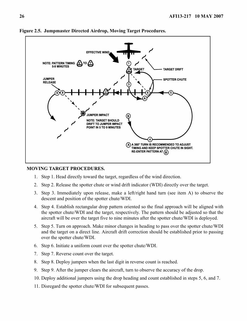
Figure 2.5. Jumpmaster Directed Airdrop, Moving Target Procedures.
MOVING TARGET PROCEDURES.
1. Step 1. Head directly toward the target, regardless of the wind direction.
2. Step 2. Release the spotter chute or wind drift indicator (WDI) directly over the target.
3. Step 3. Immediately upon release, make a left/right hand turn (see item A) to observe thedescent and position of the spotter chute/WDI.
4. Step 4. Establish rectangular drop pattern oriented so the final approach will be aligned withthe spotter chute/WDI and the target, respectively. The pattern should be adjusted so that theaircraft will be over the target five to nine minutes after the spotter chute/WDI is deployed.
5. Step 5. Turn on approach. Make minor changes in heading to pass over the spotter chute/WDIand the target on a direct line. Aircraft drift correction should be established prior to passingover the spotter chute/WDI.
6. Step 6. Initiate a uniform count over the spotter chute/WDI.
7. Step 7. Reverse count over the target.
8. Step 8. Deploy jumpers when the last digit in reverse count is reached.
9. Step 9. After the jumper clears the aircraft, turn to observe the accuracy of the drop.
10. Deploy additional jumpers using the drop heading and count established in steps 5, 6, and 7.
11. Disregard the spotter chute/WDI for subsequent passes.

AFI13-217 10 MAY 2007 27
Figure 2.5. Jumpmaster Directed Airdrop, Moving Target Procedures (continued).
1. When the target drift rate is changed (drogue chute is installed on target, no wind shift occurs, etc.) the entire spotter chute/WDI procedure must be re-accomplished and a new drop heading and count estab-lished starting with step 1.
MOVING TARGET PATTERN. Deployment procedures to a moving target are similar to those employed for a stationary target. The moving target procedures takes into consideration target drift and will place the team on the downdrift line of the moving target and not necessarily on target. Special atten-tion should be paid to the following items:
1. The pattern must be adjusted so that the initial pass over the target after spotter chute/WDI deployment is not less than 5 minutes and not more than 9 minutes, 7 minutes being ideal. If the initial pattern requires more than 9 minutes, the team will be too far downdrift/downwind and with a high target drift rate may not be able to locate the target visually.
2. On the initial pass after the spotter chute/WDI deployment, an accurate count can be obtained by the JM and the heading noted by both the JM and pilot. All subsequent passes will be made on this initial heading using the count obtained on the first pass. No attempt should be made to recheck the count or change the initial heading because the target will have drifted.
NOTE: On subsequent passes requiring a change of heading to place the aircraft over the target, ensurethe pilot corrects back to original heading. Moving target procedures are normally conducted fromfixed-wing aircraft.
2.12. Airdrop Communications. To the maximum extent possible, airdrop operations should beplanned to operate with minimum radio transmissions. In general, all missions are flown as planned withadditional radio calls made “by exception” only. Authentication is accomplished as required. Detailedmission planning and pre-briefed operating procedures can eliminate many flight-following and forma-tion-only transmissions. Radio contact with the drop aircraft should be limited to safety of flight require-ments or issues affecting airborne force employment. This includes ATC directions, range clearance,unsafe surface conditions or mission changes. DZ winds or other information may be broadcast in theblind at a coordinated time prior to the scheduled TOT.
2.12.1. Drop clearance to a marked DZ is normally inherent with mission clearance and is confirmedby the aircrew observing the pre-briefed visual DZ markings. Unless radio communications are spe-cifically required, any coordinated markings, other than red smoke, red flares, or red lights indicate aclearance to drop.
NOTE: During NVG operations colored flares may still be used, but due to the delay in aircrew recogni-tion of color, star clusters or other obvious signals are recommended.
2.12.2. Training airdrops (both unilateral and joint) conducted during IMC or to an unmarked DZrequire the DZC to relay drop clearance, (i.e., “Cleared to Drop”), to the aircraft by way of radio com-munications or other pre-briefed method. Drop clearance is usually accomplished a minimum of 2minutes prior to the scheduled TOT.
2.12.3. Mission clearance provides drop clearance on operational missions to DZs where no receptionparty is present.

28 AFI13-217 10 MAY 2007
2.12.4. No-Drop Signals. A “NO-DROP” condition, closing of the DZ, or temporary closing of theDZ will be indicated in one of the following ways: an authenticated radio transmission, red smoke, redflares, red lights, scrambled panels, or another planned signal.
NOTE: During NVG operations colored flares may still be used, but due to the delay in aircrew recogni-tion of color, star clusters or other obvious signals are recommended.
2.12.4.1. A “NO-DROP” situation during IMC operations will be indicated by the absence ofpre-briefed electronic device(s), or an authenticated radio transmission.
2.12.4.2. Use standard no-drop signals to communicate temporary closing of a drop zone or post-ponement of an airdrop. Aircrew should follow up with a radio call to the appropriate C2 facilityas the situation dictates.
2.12.5. When using radio communications, the following procedures apply:
2.12.5.1. “NO DROP” advisories should be transmitted early enough to allow time for authenti-cation; specifically, not later than 1 minute prior to actual TOT, unless an emergency arises.
2.12.5.2. If last minute conditions preclude a safe drop and time for proper authentication is notavailable, the DZC will immediately and repetitively transmit cancellation of drop clearance,“NO-DROP, NO-DROP, NO-DROP.”
2.12.6. Authorized Relays:
2.12.6.1. Relay operational information to the aircraft as requested when abnormal conditionsnecessitate such requests. DZCs should not be required to handle such messages on a regularbasis.
2.12.6.2. If necessary, inform the aircraft of the source of any messages being relayed (DZSO,DZC, ground forces commander, etc.).
2.12.6.3. Transmitting the reason for an aircrew initiated “NO-DROP” is not normally required.However, if time permits, the aircrew will pass the information to the DZC. For a ground initiated“NO-DROP” (if time and security requirements permit) the DZC will inform the aircrew of thereason and should coordinate any further action.
2.12.6.4. During airborne operations, the ground forces commander may need to determine thenumber of personnel who did not jump (alibi jumpers) to properly account for all personnel. Whenrequested by the DZSO/DZ Support Team Leader (DZSTL), if the tactical situation permits, theDZC obtains the total number of jumpers remaining on board from the aircrew. This should not beaccomplished until after the last aircraft over-flies the DZ and at no time if it compromises safetyor conflicts with aircrew or DZC duties. Should such a conflict occur, delay or cancel transmis-sions accordingly.
2.12.7. Unauthorized Relays. Radio calls to determine order of flight, load information, and adminis-trative details are normally not authorized.
2.12.8. Only qualified DZ personnel will operate DZ communication equipment.
2.13. Control Point Location. The DZC establishes the control point taking into account pertinent fac-tors such as an unobstructed line of sight, winds, positive control of the DZ, surrounding airspace, andsecurity requirements. Safety factors must always be considered when choosing a control point location.

AFI13-217 10 MAY 2007 29
During actual IMC, HV CDS or HAARS, locate the control point off the DZ. The control point formulti-ship HE and all CDS equipment airdrops will be offset a minimum of 300 yards (HE) and 200 yards(CDS) from the intended PI.
2.14. En Route and Terminal NAVAIDS. A variety of electronic NAVAIDS are available to supportdrop zone operations including the TACAN, ZM, or radar beacons. These NAVAIDS are utilized at thediscretion of the JFACC, JFSOCC, or mission commander.
2.14.1. For airdrops, the normal placement for NAVAIDS is as follows:
2.14.1.1. The ZM (TPN-27) should be placed within 1,500 yards of the PI. For maximum accu-racy, the ZM should be as close to the PI as possible. If line-of-sight considerations precludeplacement of the ZM at the briefed location, relocate it and advise the aircraft on initial contact ofthe new location relative to the PI. During night airdrop operations, the ZM should be visuallymarked with a light to identify it as a hazard to parachutists and to prevent accidental destructionof the ZM by vehicular traffic.
2.14.1.2. Radar Beacon Operations. Special Tactics units maintain several different radar beaconsystems to include the SST 181, SMP 1000, and PPN-19. Pre-briefed/pre-coordinated beacon useis required to ensure the proper beacon at the proper setting is established.
2.14.1.2.1. For CARP airdrops, compute the wind drift distance for the load being droppedand displace the beacons the computed distance and direction into the wind from the PI.
2.14.1.2.2. For high altitude airdrop operations, place radar beacons on the PI. Aircrews andDZC must ensure that the PI coordinates are IAW Table 2.1. high altitude minimum DZ sizerequirements. High altitude airdrop PI’s will be greater than Table 2.2. standard point ofimpact placement after Table 2.1. minimum DZ size, length and width adjustments are made.
2.14.1.2.3. For MFF airdrops, the beacons will be placed on the PI.
2.14.1.2.4. The TACAN should not be placed on a DZ as an airdrop aid.
2.15. Ground Marked Release System. When controlling an airdrop, the DZC can mark a point on theground with a visual signal to designate the computed Release Point (RP) to the aircrew. This signal maybe a four marker “L”, six marker “T”, or seven marker “H” and is placed abeam, and 100 meters (110 yds)left of the desired release point as depicted in Figure 2.6. The drop is executed when the aircraft isdirectly abeam, and 100 meters (110 yds.) right of this marker on the pre-briefed inbound heading. Apre-briefed code signal or beacon may be collocated with the markers to aid in DZ identification.

30 AFI13-217 10 MAY 2007
Figure 2.6. Ground Marked Release System Day and Night Markings.
2.15.1. Marking Considerations:
2.15.1.1. The DZ markings must be clearly visible to the aircrew on approach as early as possible.If conditions preclude placing the markings at the computed point, the DZC may have to adjust thelocation of the intended PI, ensuring compliance with the requirements in Table 2.1., Table 2.2.,and Figure 2.1., Figure 2.3., Figure 2.4., Figure 2.5. Advise both the aircrew and user of thechange in PI location.
2.15.1.2. When conducting operations requiring security, night DZ markings should be visibleonly from the direction of the aircraft’s approach. If flashlights are used, they should be equippedwith simple hoods or shields and aimed toward the approaching aircraft. Omni directional lights,fires, or improvised flares may be screened on three sides or placed in pits with the sides slopingtoward the direction of approach.
2.15.1.3. During daylight airdrops, the marker panels should be slanted at a 45-degree angle fromthe surface toward the aircraft approach path to increase the aircrew's ability to see them. If secu-rity permits, smoke (other than red) may be displayed at the release point or corner marker toassist in aircrew DZ acquisition.
2.15.2. Determining PI Location.
2.15.2.1. After selecting the DZ, calculate the dispersion distance, as stated below, and then selecta PI that is compatible with the calculated point and the tactical situation. Once the PI has beendetermined, calculate the forward throw distance and wind drift effect to determine the releasepoint.

AFI13-217 10 MAY 2007 31
2.15.2.2. Dispersion distance is defined as the total distance within the impact area where troopsor cargo will land. It is in a direct line with the aircraft’s line of flight and is dependent upon air-craft speed and load exit time (the length of time required for the first through the last object toclear the aircraft). The formula for calculating dispersion is; ½S x E = L, where S = aircraft speedin knots, E = exit time in seconds, and L = length of dispersion in yards. This calculation is nor-mally used to help in placing the PI, rather than determining the release point.
2.15.2.3. Wind drift is defined as the lateral movement of a parachute through the air caused bythe wind. The distance of the wind drift is measured on a direct line from the parachute’s fullydeployed opening point to its actual point of impact on the ground. This drift is calculated usingthe formula; D = KAV, where D = drift in yards, K = the load drift constant, A = drop altitude inhundreds of feet) i.e., (1,000 feet = 10), and V = wind velocity in knots. Table 2.6. depicts the con-stants for different airdrop loads.
2.15.2.4. Forward throw distance is the distance along the aircraft flight path traveled by a para-chutist or cargo container after exiting the aircraft, until the parachute fully opens and the load isdescending vertically (Table 2.7.).
Table 2.6. Ground Marked Release System/Verbally Initiated Release System Load Drift Constants (K).
Table 2.7. Ground Marked Release System/Verbally Initiated Release System Forward Throw Distance Data.
TYPE DROP K (Load Drift Constant) Personnel (Static Line) 3.0 Heavy Equipment 1.5 CDS/CRL/CRS 1.5 HVCDS Zero Door Bundle 1.5 SATB 2.4
TYPE DROP C-130 C-17 Personnel (Static Line) / 250 yds 250 yds Door Bundle (229 m) (229 m)
Personnel (MFF) 328 yds (300 m)
328 yds (300 m)
Heavy Equipment 500 yds (458 m)
700 yds (640 m)
CDS/CRS/CRL 550 yds (503m) 725 yds (663 m)
SATB 160 yds (147m) N/A

32 AFI13-217 10 MAY 2007
2.15.2.5. Offset is defined as the distance the aircraft will fly to the right of the marker (100meters) so the markers will remain visible to the aircrew.
2.15.3. Ground Marked Release System (GMRS) marking placement techniques:
2.15.3.1. Stand on the PI facing toward the direction from which the aircraft will approach (recip-rocal of DZ axis).
2.15.3.2. Pace off the distance calculated for forward travel distance. Record the position coordi-nates as a GPS markpoint/waypoint.
2.15.3.3. Face directly into the wind. Pace off into the direction of the wind the distance calcu-lated for wind drift. This is the actual release point
2.15.3.4. Face into the direction from which the aircraft will approach (reciprocal of DZ axis),turn 90 degrees to the right and pace off 100 meters (110 yards for the offset). Place the corner orfirst panel at this point.
2.15.3.5. Adjust the release point for wind direction/velocity changes by returning to GPS mark-point/waypoint and following steps 2.15.3.3. and 2.15.3.4. above.
2.15.3.6. Establish the ground markings as shown in Figure 2.6.
2.16. Verbal Initiated Release System. CCT, pararescue, and battlefield weather personnel use this pro-cedure when normal drop procedures are not tactically feasible. The ground party determines the desiredrelease point, gives verbal steering guidance to the pilot to align the aircraft over that point, and then ini-tiates the release. Instructions transmitted to the aircraft must be concise.
2.16.1. Transmit “Turn Left” or “Turn Right” to align aircraft on desired inbound heading.
2.16.2. Transmit “Stop Turn” after alignment instructions when aircraft is on course.
2.16.3. Transmit “Standby” to the aircraft approximately 5 seconds prior to the release point.
2.16.4. Transmit “Execute, Execute, Execute” when the aircraft reaches the release point. Upon hear-ing the first "Execute", the navigator/pilot not flying calls "Green Light."
2.17. Drop Zone Personnel. The DZ Controller (DZC) is normally a USAF combat controller (E-4 orabove with a five skill level or higher) certified by the unit commander. Combat controllers are authorizedto control all airdrops for any US or allied military force.
NOTE: Combat Rescue Officers, Pararescue, RQS assigned or supporting SERE Specialists, and Battle-field Weather personnel are authorized to act as DZC for unilateral AF and foreign national rescue opera-tions in which Pararescue is the controlling agency. DZC training and certification for rescue parachutedeployments may be accomplished by qualified Pararescue trainers/task certifiers and certified by letterby the unit commander.
2.17.1. The primary method of certification is to complete the HQ AFSOC DZC formal lesson planand instruction by a qualified combat controller, qualified AMLO, DZC certified rated officer aircrewmember, unit certified DZC personnel, or a sister service Drop Zone Support Team (DZST) IAW2.17.4. All Air Force DZCs, other than combat control personnel and AMLOs, will be trained to attainproficiency (academic training and practical training involving day and night DZ operations) in DZCresponsibilities, duties, and DZ establishment as outlined in this instruction and operations support

AFI13-217 10 MAY 2007 33
squadron training procedures. Certification will be validated in a memorandum signed by the opera-tions group commander (OG/CC) and maintained at the group tactics office. Air Force aircrew mem-bers functioning as DZCs are restricted to a 12-hour duty day waiverable to 16 hours by the OG/CC orhigher (not applicable to AFRC crewmembers). AMLOs deployed/attached in support of US Armyunits get duty-day extensions from supported forces commander or as designated supported forcesauthority by respective Division Commander. The alternate method of DZC certification is to com-plete the training IAW the HQ AFSOC lesson plan provided by a qualified combat controller. How-ever, due to the high ops tempo of special tactics teams, scheduling training through a special tacticssquadron may require extensive lead time between the coordination process and the actual trainingcommence date. The HQ AFSOC DZC lesson plan can be accessed through a link on the AMC/A3D– Combat Operations web-site at: https://private.amc.af.mil/a3/a39/a39.htm
NOTE: Authorized personnel, other than qualified combat controllers, qualified AMLOs and DZC certi-fied rated officer aircrew members, are restricted to formation airdrops of four or less aircraft unless on amilitary range with active range control.
2.17.2. USAF personnel other than ST.
2.17.2.1. Air Mobility Liaison Officers (AMLO). AMLOs qualified IAW AMCI 13-101, AirMobility Liaison Officers, are authorized to control airdrops for any U.S., allied or coalition mili-tary force.
2.17.2.2. The OG/CC may approve active duty, ANG, AFRC members, and civilian contract per-sonnel to perform DZC duties during unilateral training airdrops. The OG/CC should utilize airoperations oriented personnel to act as DZCs. Although not all encompassing, aircrew, tactical aircontrol party (TACP), battlefield weather personnel, air traffic control, aerial delivery support,pararescue, and jumpmasters (currently on jump status) are some of the AF specialties/qualifica-tions that are routinely involved in air operations. See MAJCOM guidance for additional DZC eli-gibility and restriction criteria. Individuals may be certified after completion of the requiredtraining listed in paragraph 2.17.1.
NOTE: Properly trained USAFWS Weapons Officer airlift cadre may perform DZC duties at allapproved CONUS DZs. These personnel assume DZCO and DZSO responsibilities listed in 2.18. and2.19. Weapons Officers will receive HQ AFSOC formal training from a 7-level combat controller (pre-ferred) or training from any appropriately trained DZC IAW para 2.17.1.
2.17.3. Other DoD Authorized DZC Personnel.
2.17.3.1. Civilian contract personnel must complete the HQ AFSOC formal lesson plan andreceive instruction IAW paragraph 2.17.1. before they are authorized to control airdrop operations.
2.17.3.2. U.S. Special Operations Command (USSOCOM) units. In addition to Air Force STunits, the following USSOCOM units have qualified personnel that may perform DZC duties dur-ing joint and unilateral USSOCOM training.
2.17.3.2.1. U.S. Navy Sea Air Land teams and Explosive Ordinance Disposal units.
2.17.3.2.2. U.S. Army Special Forces and Rangers.
2.17.4. Drop Zone Support Team (DZST) Personnel. DZSTs are qualified IAW the Memorandum ofAgreement (MOA), “Airdrop Operations Without Air Force Combat Control,” and unit standard oper-ating procedures implementing this MOA.

34 AFI13-217 10 MAY 2007
2.17.4.1. U.S. Army/Marine Corps DZST personnel may perform DZC duties during joint andunilateral Air Force training airdrops.
2.17.4.2. DZST controlled missions must have a qualified Drop Zone Support Team Leader(DZSTL) in charge of DZ operations.
2.17.5. Non-USAF / Non-aircrew personnel. If combined exercises or contingency operations requireUSAF use of drop zones not defined within the scope of this AFI, or under the operational control ofnon-USAF / non-aircrew personnel, a combat controller or AMLO may train allied forces personnel(with ACC or DIRMOBFOR approval) to perform DZC duties IAW paragraph 2.18. of this instruc-tion using approved HQ AFSOC formal lesson plans. The instructor will provide a letter certifyingpersonnel to perform DZC duties limited to the drop zone trained on for a specified duration.
2.18. Drop Zone Controller Responsibilities.
2.18.1. The DZC represents the appropriate commander as provided in the mission directive.
2.18.2. The DZC ensures that adequate medical and evacuation coverage is available prior to person-nel airdrops.
2.18.3. The DZC observes and evaluates:
2.18.3.1. All factors that may adversely affect the safety of the operation and ensures transmissionof weather information when required.
2.18.3.2. Condition of the DZ prior to the airdrop.
2.18.3.3. Placement of personnel and equipment on the DZ. Only designated vehicles and person-nel will remain on the DZ. Recovery and medical personnel and equipment must be positioned sothat constant contact is maintained with the DZC. During joint operations, the DZC and the DZSOare responsible for their respective equipment and personnel.
NOTE: For actual equipment or personnel airdrops, if the ceiling is less than 600 feet, direct all person-nel and equipment off the DZ to ensure safety.
2.18.3.4. The operation of other aircraft that could endanger the drop aircraft, equipment load, orparachutists.
2.18.3.5. The DZC should have immediate access to ground-to-air communications equipment orsufficient signaling aids to operate the DZ. Ground-to-air communication is required for IMC air-drops.
2.18.3.6. The DZC insures non-DZC personnel are aware of the “NO DROP” signal in order toprevent an inadvertent signal to the aircraft.
2.18.4. In the event conditions are unsafe for airdrop operations, the DZC ensures that:
2.18.4.1. "NO DROP” signals are displayed on the DZ.
2.18.4.2. “NO DROP” or drop cancellation information is transmitted to the aircraft (see para-graphs 2.12.4. and 2.12.5.).
2.18.4.3. A drop is canceled when advised by the DZSO. During a joint mission, the DZSO isresponsible for evaluating the winds and surface conditions for an airdrop operation. When only

AFI13-217 10 MAY 2007 35
AF personnel are involved, it is the responsibility of the DZC to cancel the airdrop when condi-tions are unsafe.
2.18.4.4. Ensures necessary reports to include AF Form 4304, Drop Zone / Landing Zone ControlLog (Attachment 7), are properly filled out and submitted to the appropriate agencies.
2.19. Drop Zone Safety Officer. During training operations, the airdropped force furnishes the DropZone Safety Officer (DZSO) who in turn is responsible for the following functions (DZC/DZSO dutiesmay be combined during unilateral USAF operations):
2.19.1. Ensuring adequate medical coverage is available at the DZ prior to any personnel drops. Thesupported unit normally provides medical coverage for itself and Air Force parachutists during jointoperations.
2.19.2. Clearing the DZ of all personnel and equipment not required for control.
2.19.3. Determining when surface conditions (i.e., winds, vehicles, etc.) on the DZ are hazardous toairborne operations, making the decision to proceed with, suspend or cancel airdrops, and informingthe DZC not later than 2 minutes prior to the drop. Airdrops are not suspended or canceled basedsolely on aircraft alignment with the DZ.
2.19.4. Coordinating all no-drop actions with the DZC.
2.19.5. Ensures the conditions of the DZ will not affect operations or recovery of air items.
2.19.6. Ensures the DZ meets operational and safety criteria for the type airdrop operations beingconducted.
2.20. Drop Zone Scoring. Drop scoring is the responsibility of the DZC.
2.20.1. Strike Reports. The strike report reflects the circular error (CE) or the distance that the firstobject (or parachutist) lands from the PI. Strike reports are given in yards or meters and relative clockposition from the PI with 12 o’clock as the relative DZ axis heading.
2.20.1.1. Score object impacting within a 25-yard radius of the PI as a “PI”.
2.20.1.2. Score the accuracy of mass airdrops during joint training, exercises, SOF standardiza-tion / evaluations, and high velocity airdrops as “Satisfactory” if 90 percent or more of all air-dropped personnel or equipment lands within the boundaries of the DZ. Score these drops as“Unsatisfactory” if less than 90 percent lands within these boundaries. Mass airdrops for person-nel are considered approximately brigade size or larger. Both personnel and equipment airdropsmay be scored using mass airdrop criteria if the accuracy is indeterminable.
2.20.1.3. MFF Airdrops. Do not score MFF airdrops. Annotate actual TOTs and information rele-vant to any mishap or off-DZ drops.
NOTE: Waivered DZ drops are scored based on the AF minimum DZ size criteria. For example, awaivered DZ is 100 yards short of AF minimum size. The drop is considered on the DZ if personnel/equipment land within the 100-yard difference between the minimum and wavered DZ boundaries.
2.20.2. Scoring Methods. There are three methods to score airdrops, and they are listed by preference.
NOTE: Score only the first load/parachutist exiting from each aircraft.

36 AFI13-217 10 MAY 2007
2.20.2.1. Measuring. The distance from the PI to the load is measured when precise scores arerequired. The distance is measured using a precision measuring device (odometer, laser rangefinders, pre-measured length of cord, measuring tapes, cyclometer, GPS, etc.).
2.20.2.2. Pacing. Score is measured by physically pacing the distance from the PI to the placewhere the parachutist or equipment load landed.
2.20.2.3. Estimating. Used when there is insufficient time or personnel to pace. The distance fromthe PI to the load is visually estimated. To assist in scoring by this method, markers (visible fromthe PI) may be placed at desired locations from the PI at the 3, 6, 9, and 12 o’clock positions. If themarkers are used, indicate this to the aircrew.
2.21. Off Drop Zone Reporting Procedures. In addition to the paragraphs below, users will refer toAFJ 13-210(I), Joint Airdrop Inspection Records, Malfunction Investigations, and Activity Reporting.
2.21.1. When an off DZ airdrop has been confirmed or suspected, the aircrew involved will notattempt another drop for the remainder of the mission. In the case of an off DZ drop involving injuryor death to personnel, the mission will be terminated and the aircraft will land as soon as possible.Retain all paperwork involved in the flight to aid in the investigation. Aircrews will immediatelyreport information regarding off DZ airdrops to a USAF Command Post. Unit safety offices will benotified as soon as possible. Off DZ mishaps resulting in death or serious injury shall be referred tosafety and accident investigation boards convened under the appropriate regulations.
2.21.2. Units with DZC/DZSO/DZST responsibilities will develop local procedures and communica-tions processes to obtain emergency assistance to preserve life and limb, secure the site, and notify theairlift and user's chain of command. The first notification step should be through the airdrop aircraftfor relay to a USAF command post. Alternative means may include relay through any local US mili-tary installation. Local installations may also be able to assist with emergency response resourcesincluding, aircraft rescue and fire fighting, law enforcement, and public affairs.
2.21.2.1. Wings/operations groups will develop guidance for aircrews and DZ personnel for thecapture and reporting of in-flight data relating to an off-DZ airdrop and/or airdrop malfunction.This data must have enough detail to re-create the circumstances surrounding the incident for theaerial delivery review panel. Accurate and timely capture of data is critical and is the responsibil-ity of the aircraft commander.
2.21.2.2. Aircrews involved in an airdrop malfunction will not attempt another drop for theremainder of the mission until approved by the unit’s OG/CC, DIRMOBFOR, or USAF base OG/CC with airdrop expertise from which the mission was launched and returned.
2.21.3. The aircrew’s OG/CC, or equivalent, shall appoint an aerial delivery review panel to investi-gate all off DZ airdrops. However, when performing off-station airdrop missions at an Air Force Basewith airdrop expertise (e.g. Pope AFB), the aircrew’s OG/CC may authorize the host unit OG/CC toperform the aerial delivery review panel IAW paragraph 2.21.5. Panel members should include theOperations Support Squadron (OSS) chief of tactics (chairperson); a tactics pilot, navigator, and load-master; a stan/eval pilot, navigator, and loadmaster; airdrop inspector loadmaster, flying safety officer,and crewmembers from the incident. The chairperson may modify panel composition based on thenature of the situation under review.
2.21.4. The Flying Safety Officer will determine if the airdrop incident is reportable in accordancewith AFI 91-204, Safety Investigations and Reports. The aerial delivery review panel will be prepared

AFI13-217 10 MAY 2007 37
to provide information requested for a safety investigation and report, if warranted. Normally, the AirForce reports injuries and damage to their own personnel and equipment. Other military servicesreport injuries and damage to their own personnel and equipment. The Air Force takes part in theseinvestigations when requested by the other service.
2.21.5. Convene an aerial delivery review panel no later than the next duty day after the airdrop if theincident occurs in the local area. However, if the incident occurs away from home station at a locationwithout Air Force airdrop expertise, convene the panel within 5 duty days (10 days for ANG andAFRC units) after the aircrew returns to home station. The unit’s OG/CC is the approval authority toallow aircrew to continue airdrop operations away from home station at a location without USAF air-drop expertise. Unit commanders will ensure aircrew members involved in an off DZ airdrop are notscheduled for any event that would delay convening an aerial delivery review panel or for another air-drop until the incident is resolved. Upon completion of the aerial delivery review panel, the chairper-son will submit recommendations to the OG/CC; if the option listed in paragraph 2.21.3. is used, thenthe host unit OG/CC will inform the aircrew’s OG/CC of the panel’s recommendations. The OG/CCwill make the final determination regarding any panel recommended actions.
2.21.6. HQ AMC/A3DT will be the repository for all Air Force off DZ reports. AMC units will sendthe results of their delivery review panel by memorandum, message, or e-mail to HQ AMC/A3DTwithin three duty days after the panel convenes. Non-AMC units will forward their report to AMC/DOKT through their MAJCOMs NLT 30 calendar days after the incident. If the aerial delivery reviewpanel judges the incident to be of immediate interest to other airdrop units, send an immediate mes-sage outlining significant details and recommendations to HQ AMC/A3DT with an information copyto the parent numbered Air Force (NAF).
2.21.7. As a minimum, the delivery review panel results will include the following information intheir final report: date of incident, type aircraft, unit, type load, DZ name and location, type drop(SKE, Visual, or Computer Drop), day/night, formation position, drop score (clock position and dis-tance), and surface winds. The report will also include causes and recommendations.
2.22. Drop Zone Surveys.
2.22.1. USAF aircrews require a DZ survey for training airdrop missions involving US personneland/or equipment. Completing the DZ survey process involves both a physical inspection of the DZ,and documenting the information on AF IMT 3823, Drop Zone Survey. Surveys may be accomplishedby the unit whose equipment or personnel are being airdropped. For exercises and joint training oper-ations, users must ensure the survey is completed and meets the appropriate criteria for operationaland safety standards. If requesting ST combat controllers to conduct the survey IAW paragraph 1.4.the user should identify this requirement during the initial planning conference but no later than themiddle planning conference. The user must conduct a physical inspection of the DZ prior to use toidentify and evaluate potential hazards to airdropped personnel/equipment, man-made or naturalstructures, and ground personnel. The nearest group tactics office will perform the safety-of-flightreview to ensure there are no obstructions prohibiting over-flight. If the survey was conducted usingany other method than GPS-derived coordinates, provide the safety-of-flight reviewer with the rawcoordinate data and the method of conversion. If a DZ survey is done on an existing surveyed DZ tomeet new run-in axis requirements for a particular mission, only a safety-of-flight review is required.
2.22.1.1. Host Nation (HN) DZ Surveys. When dropping HN military jumpers and/or equipmenton a HN surveyed DZ, the mission can be performed using only a safety-of-flight review (see

38 AFI13-217 10 MAY 2007
2.22.1.2. below) of the HN survey. Users remain responsible for ground operational and safety cri-teria IAW 2.22.1. above. However, when US personnel and equipment are airdropped, HN sur-veys will not be used in lieu of a survey completed by US forces IAW survey procedures outlinedin paragraph 2.22.
2.22.1.2. Safety-of-Flight Review. A safety-of-flight review is completed by the nearest Air Forcewing/group tactics office on all DZ surveys. During contingency operations, the safety of flightreview may be accomplished by the tactics office in the Air Mobility Division (AMD) / AOC. Thepurpose of a safety-of-flight review is to ensure an aircraft can safely ingress and egress the DZ. Asafety-of-flight review includes an in-depth chart study of the terrain features along the route offlight from the IP to a distance of approximately 4 nautical miles past the DZ trailing edge. For acomplete list of Regional Group/Wing Tactics offices see: https://afkm.wpafb.af.mil/ASPs/CoP/OpenCoP.asp?Filter=OO-OP-AM-40
2.22.1.2.1. A 1:50,000-scale chart and satellite imagery (if available) should be used whenavailable for the objective area and at least a 1:250,000-scale chart for the run-in and escape.If approved by the MAJCOM, Portable Flight Planning Software (PFPS) may be used insteadof paper charts. The safety-of-flight review lists (Block 11 of AF IMT Form 3823 IAWAttachment 4 paragraph A4.1.11.) all obstructions such as terrain, towers, or power lines thatmay affect the aircraft’s ability to achieve drop altitude and airspeed. Also listed on thesafety-of-flight review are any prohibited areas, noise sensitive areas, special use airspace,route of flight to avoid such areas, preferred routing, Notice to Airmen (NOTAM) require-ments, etc. Evaluation of terrain/ obstructions should include service ceiling and climb perfor-mance for the particular aircraft involved, the ability of the aircraft to fly over the DZ at slowspeeds and escape from the DZ using three-engine climb out rates. If these criteria cannot bemet, the run-in must be modified, drop altitude raised, or the safety-of-flight review denied.
2.22.2. When conducting operations on a DZ that was previously surveyed by another unit, the com-mander of the using unit is responsible for ensuring the DZ meets the criteria for that operation. In allcases, the using unit must accept responsibility for all personnel injuries, parachute or load damage,and property damage occurring on the DZ.
2.22.3. Tactical DZ Surveys. During exercises and contingencies, when time or situation do not per-mit completion of a full DZ survey, a tactical DZ survey may be required to support highly mobileground forces.
2.22.3.1. Though preferable, the use of an AF IMT 3823, Drop Zone Survey, is not required for atactical survey. Requests and surveys may be passed electronically. As much information as prac-tical should be obtained and forwarded for review.
2.22.3.2. Requests for tactical surveys will be forwarded to the designated exercise/contingencyairlift or special operations component senior representative for final review.
2.22.3.3. When using a tactical DZ, the airlift unit assumes responsibility for aircraftsafety-of-flight and the receiving unit assumes responsibility for injury to personnel or damage toequipment/air items. The DZ size should be determined by the mode of delivery, load dispersal,and discussion with receiving unit regarding air item recoverability and load survivability.
2.22.4. Parachute Demonstration Team DZ Surveys. The Air Force “Wings of Blue” and MAJCOMsponsored parachute demonstrations do not require a formal DZ survey for public affairs coordinatedhigh altitude low opening (HALO) precision parachute demonstrations using Air Force aircraft. It is
AFI13-217 10 MAY 2007 39
the responsibility of the demonstration team leader/jumpmaster to ensure all service, FAA, and host-ing organization requirements are met on and around the DZ. It is the responsibility of the flying unitto ensure flight safety will not be compromised and that applicable NOTAMs are filed with the FAA.It is the responsibility of both the flying unit and the demonstration team leader/jump-master to ensureall aspects of the planned operation are briefed and understood by all parties involved.
2.23. Drop Zone Review Process. The following paragraphs outline the DZ review process from per-forming the initial groundwork to the final incorporation of the DZ into the ZAR. Use of the ZAR willexpedite mission planning, enhance safety, and avoid duplication of surveys. Information in the ZAR doesnot replace the need for a completed survey prior to conducting drop zone operations. All completed sur-veys will be forwarded by the appropriate agencies to HQ AMC/A3DT for inclusion in the worldwideZAR database.
NOTES:DZ surveys become obsolete 5-years after the date of MAJCOM approval (block 4E on AF Form 3822)and must be resurveyed prior to use. Surveys will also be reaccomplished when the user and/or airlift pro-vider determines changes in the ground or air aspects of the DZ data require a new survey.
Other MAJCOMs and contingency AOCs may maintain their own ZAR database (if desired). However,this does not alleviate them of the responsibility to provide these surveys to HQ AMC/A3DT for inclusionin the worldwide ZAR database, unless classification requirements dictate otherwise.
2.23.1. The surveyor (AF IMT 3823, item 4A2) performs the actual ground portion of the DZ survey(i.e., measurements, coordinates, calculating size, obtaining maps and creating diagrams) and anno-tates results on the AF IMT 3823 . The surveyor may be a member of the unit that intends to use theDZ, a member of another unit, or a qualified civilian. A qualified civilian may be a GS employee, con-tractor, and/or temporary contractor hired by DoD to perform survey specific duties. All civilian qual-ified members will be trained IAW the current AFSOC survey training guidance. All surveyors mustbe capable of performing the required survey duties and be familiar with equipment and data compu-tations necessary to complete the survey in order to ensure survey accuracy. To facilitate future use ofsurveyed DZs, initial surveys will encompass the largest area available and will not be limited by spe-cific mission requirements. The surveyor will forward the completed survey to the ground operationsreview authority. Include recommended use, any deviations from DZ standards contained in service orMAJCOM directives, and other pertinent remarks. Throughout the review process, DZ survey pack-ages will include all applicable maps, photos, charts and diagrams necessary to determine the safetyand utility of the DZ.
NOTE: Interested users may contact the Combat Control School, DSN 424-1406, to obtain slots in theSurvey Course. Slots will be on a space-available basis to all non-CCT personnel.
2.23.2. The ground operations review authority (AF IMT 3823, item 4C) is normally the surveyor’scommander or designated representative. This review ensures the survey form is complete, accurate,and the DZ meets the criteria for planned ground operations.
2.23.3. The safety-of-flight reviewer (AF IMT 3823, item 4D) performs the safety-of-flight reviewensuring that the DZ can be safely used from a flight perspective. The safety-of-flight review is com-pleted by the chief, group tactics, or as assigned by the OG/CC or equivalent.

40 AFI13-217 10 MAY 2007
2.23.4. Air Operations Approval. (AF IMT 3823, item 4E). Prior to use, surveys will be approved forair operations by the OG/CC or the appropriate ACC, respectively. This approval assures that thesafety-of-flight review has been accomplished and the DZ is considered safe for air operations.
2.23.5. Once item 4E of the AF IMT 3823 is completed, the survey is ready for use. All completedsurveys will be forwarded to HQ AMC/A3DT, 402 Scott Drive, Unit 3A1, Scott AFB, IL 62225-5302,to maintain the most current data in the ZAR database. Respective group tactics offices are the localarea repositories for DZ surveys.
2.23.6. DZ surveys document the conditions that existed at the time the survey was accomplished.Recommended uses may be based on minimum requirements and should not be misconstrued to beall-inclusive; (i.e., a DZ recommended for personnel may be suitable for a single parachutist but notfor 15, or it may be suitable for a C-130 but not a C-17). It is the responsibility of the supporting forceand supported forces involved to ensure that any DZ being considered for use meets the requirementsfor their specific operation.

AFI13-217 10 MAY 2007 41
Chapter 3
LANDING ZONE OPERATIONS
Section 3A—Landing Zone Operations
3.1. General. There are two types of airland operations that provide transportation within a theater orjoint operations area. Routine air movement is usually unopposed and uses secure airfields or well-estab-lished landing zones (LZ); the majority of these missions involve the administrative airlift of troops andequipment. Certain phases of any airlift operation, or the entire operation, may be accomplished byair-landing troops and equipment directly into the objective area. Combat control personnel normally pro-vide landing zone surveys.
NOTES:Combat controllers are authorized to use night vision goggles while controlling aircraft in terminal areas.Pararescue, combat rescue officers, battlefield weather personnel and crewmembers are authorized to usenight vision goggles for marshalling of aircraft in terminal areas if trained and certified in the procedure.
Unless otherwise specified in this chapter, the U-28A will follow the criteria identified for C-130 Opera-tions.
3.2. Airlift Mission Commander Responsibilities. The airlift mission commander selects the air tacticsand designs the flow of air movement to comply with the delivery requirements. The airlift mission com-mander establishes control through combat control personnel of all air traffic movement (traffic pattern,landing, taxi, parking, and takeoff) at Air Force operated LZs.
3.3. Landing Zone Selection. The ACC with the other component commanders and the joint force engi-neer determine the most suitable locations. JFSOCC forces determine their suitable locations fromJSOACC recommendations. In all cases, selected sites must meet AF operational requirements, groundcomponent requirements, and construction requirements.
3.4. Landing Zone Classification. The following general data is intended to correlate the Army airfieldclassification system with the Air Force classification system. The correlation of these airfields may notbe exact and specifications are dependent upon aircraft gross weight, utilization of aircraft arrestingequipment, criteria for the particular instrument approach planned, and model and type of aircraft.
3.4.1. Air Force airfields are usually constructed to standards that are based primarily on the expectedlife of the airfield.
3.4.1.1. Expedient airfields are those surfaced with dirt, membrane, landing mat, or any combina-tion of these.
3.4.1.2. The criteria in AFJPAM 32-8013, Volume II (FM 5-430-00-2), Planning and Design ofRoads, Airfields and Heliports in the Theater of Operations - Airfield and Heliport Design, out-lines construction criteria of airfields for aircraft operating under normal conditions and proce-dures. Combat control personnel are trained to perform tactical LZ surveys or assessments insupport of airlift operations. They determine LZ suitability by using general criteria in AFJPAM32-8013, Volume II (FM 5-430-00-2), and the specific tactical LZ criteria contained in MAJCOM

42 AFI13-217 10 MAY 2007
supplements to this instruction. Table 3.1. shows the general peacetime minimum sizes for vari-ous USAF fixed-wing LZs. These LZs are based upon required use of maximum effort take-off/landing procedures by arriving/departing aircraft. These procedures are defined by applicable air-craft operating manuals.
Table 3.1. Minimum Runway Criteria.
3.4.1.3. Airfield construction is generally done following the guidelines in AFJPAM 32-8013,Volume II (FM 5-430-00-2). However, criteria to be utilized in a specific theater of operations isbased on local conditions and determined by Army and Air Force staff engineers acting for thejoint force commander.
3.4.2. Potential LZ areas fall into two basic categories: prepared, and semi-prepared (unpaved). Pre-pared areas may include existing airfields, roads, highways, or other paved surfaces. Semi-preparedsurfaces are natural areas such as deserts, dry lakebeds, and flat valley floors. These surfaces offer theability to construct short airstrips for a limited use and may or may not have an aggregate surface.
3.4.3. Contingency Response Group (CRG) airfield assessment teams include Air Force Civil Engi-neering Support Activity (AFCESA) personnel that are qualified to conduct surveys of prepared andsemi-prepared LZs.
3.4.4. Combat control personnel are trained and equipped with a full suite of surveying equipmentthat can satisfactorily assess obstructions, penetrations, and approach zone clearances. They are alsotrained and have equipment used to check weight-bearing capability of LZs for both semi-preparedand prepared surfaces.
NOTE: Although qualified combat control personnel can establish usability of hard-surface LZs for tem-porary operations, it is recommended that Air Force Civil Engineering Support Activity (AFCESA) or
Width (Ft) (NOTE 1)
Type AC Length (Ft) (NOTE 1)
No Turn Required
180 Degree Turn (Normal)
180 Degree Turn (3 Point)
U-28A 2,000 30 30 30 C-130 3,000 60 60 50 (NOTE 2) MC-130 3,000 60 60 50 HC-130 3,000 (NOTE 4) 60 60 50 C-130J-30 3,000 60 85 75 (NOTE 2) C-17 3,500 (NOTE 4) 90 143 80 (NOTE 2) C-5 6,000 (NOTE 3) 150 150
NOTES:1. Minimum operational criteria without a waiver during peacetime operations
2. Does not include any safety margin. Increase by 10 feet for routine operations
3. Waiverable to 5,000 feet by MAJCOM/A3 or DIRMOBFOR
4. Waiverable to computed ground roll plus (+) 500 ft by the MAJCOM/A3 or DIRMOBFOR

AFI13-217 10 MAY 2007 43
some other dedicated civil engineering agency with more robust equipment (Electronic Cone Penetrome-ter, Heavy Weight Deflectometer, etc.) be utilized for sustained operations. AFCESA contact informationcan be found in any Engineering Technical Letter.
3.4.5. Combat control personnel who are graduates of the AFCESA Contingency Airfield PavementEvaluation Course are qualified to perform structural evaluations of all types of pavement surfaces(hard or un-surfaced) and determine allowable number of passes and maximum weights of aircraftthat can safely use these surfaces. When results of these structural evaluations exhibit uncharacteristicresults, these personnel are trained to forward the data to the MAJCOM pavement engineer for finaldetermination.
3.4.6. Although combat controllers and AMLOs are not qualified to perform engineering surveys,they may be required to assist the supporting forces commander as a designated representative inselecting LZ sites.
3.4.7. Semi-permanent runways are usually surveyed by engineering units and do not require a surveyby combat control personnel. However, semi-permanent and permanent installations, such as capturedenemy airfields, must be assessed for possible aircraft hazards and correct dimensions prior to use.Combat control personnel may be tasked to perform this type of assessment using criteria outlined inparagraph 3.4.1.2.
NOTE: Combat control personnel normally only conduct hard surface assessments for the theater com-mander during contingencies.
3.4.8. The combat controller or CRG airfield assessment team gathers data from the on-site survey,prepares an LZ survey package using the AF IMT 3822, Landing Zone Survey, and recommendsapproval or disapproval to the appropriate agency for use.
3.4.9. During the survey process, if there is any potential for impact or damage to the environmentdue to the construction or modification of new or existing LZs, follow the procedures within AFI32-7061, The Environmental Impact Analysis Process.
3.5. General Landing Zone Criteria. Combat controllers may be required to assist in selecting LZs.General guidelines are available in AFJPAM 32-8013, Volume 2 (FM 5-430-00-2) and ETLs. Specifictactical LZ criteria for the type aircraft involved are contained in applicable MAJCOM supplements tothis instruction. Additionally, the following general data applies to LZ criteria:
NOTE: ST units will use AFCESA ETL 04-7, C-130 and C-17 Contingency and Training AirfieldDimensional Criteria, and ETL 02-19, Airfield Pavement Evaluation, Standards and Procedures. Elec-tronic copies are available at: http://www.afcesa.af.mil/library/etl.asp?Category=Engineer-ing%20Technical%20Letters
3.5.1. Size and Terrain. LZs should be of sufficient size to permit rapid takeoff, landing, and loadingoperations. Terrain may be of soil, dirt, sand, or another suitable surface. Consideration must be givento the slope and elevation of the runway, aircraft capability, taxiways, and loading restrictions includ-ing their ability to support aircraft weight. Criteria for the layout of newly constructed LZs are listedin detail in AFJPAM 32-8013, Volume II (FM 5-430-00-2), Table 11-3. Table 3.1. shows the generalminimum sizes for various fixed-wing LZs. For criteria that are more specific, see MAJCOM publica-tions.

44 AFI13-217 10 MAY 2007
3.5.2. Environmental Impact Analysis. The proponent of the survey request (i.e., the requestingoffice, unit, or activity) is responsible for completing the AF Form 813, Request for EnvironmentalAnalysis. AF Form 813 is used to document the need for environmental analysis of certain categoricalexclusion determinations for proposed actions. This form helps narrow and focus the issues to poten-tial environmental impacts.
3.5.3. Soil Conditions. Before any short field training operations are scheduled from an unpreparedstrip, there must be a thorough investigation of soil conditions to determine whether the abrasive con-tent could adversely affect aircraft operations. Whenever possible, the weight bearing capacity of thelanding, taxiing, and parking areas must be determined. The weight bearing capacity is determinedIAW AFJPAM 32-8013, Volume II (FM 5-430-00-2).
3.5.4. LZ Surface Tolerances and Clearances. Tolerance or roughness will depend upon sheerstrength, hardness, and size of items that cause roughness. Roughness interrupts smooth rotation ofaircraft tires and interferes with marginal aerodynamic lift of flight control surfaces at slow speed.Location and frequency of surface crests or wave tops are of paramount importance. The followingitems may be used as a guide in determining suitability of runway surface, shoulders, and clear areas.Exceeding these limits may result in structural failures of the aircraft. Roughness must be minimizedfor sustained operations.
3.5.5. Traffic Area (Runway, Overruns, Taxiways, Parking Apron):
3.5.5.1. Rocks. Rocks in traffic areas must be removed, embedded, or interlocked with each otherso aircraft tires will traverse the area without causing displacements.
3.5.5.2. Soil Balls (dried cohesive dirt clods). Soil balls or dry cohesive dirt clods (clay excluded)up to 6 inches in diameter that will burst upon tire impact are allowed. Hardened clay clods thathave similar characteristics as rocks and exceed 4 inches in diameter must be pulverized orremoved from the traffic areas.
3.5.5.3. Tree Stumps. Remove all stumps; fill holes, and compact soil to the weight bearing capac-ity of the surrounding surface.
3.5.5.4. Ditches. Eliminate ditches from traffic areas. When filled, the weight bearing capacitymust be that of the surrounding area.
3.5.5.5. Plowed Fields. Contours of dirt patterns established to reduce erosion, water drain-off,and for planting preparation which have been accomplished by agricultural plowing usually con-tain a soft core and normally will not require removal. However, such dirt patterns should beexamined carefully to determine the need for removal.
3.5.5.6. Depressions and Soil Mounds. Depressions and soil mounds do not have sharp cornersand are recognized as oval or circular gradual sinks or rises. Level or fill depressions or moundsthat exceed 15 inches across the top and 6 inches in depth or height until they meet grade tolerancecriteria.
3.5.5.7. Potholes. Potholes are circular or oval in shape and are distinguished from depressions bytheir smaller size and sharp corners. Potholes must be filled if they exceed 15 inches across theirwidest point and 6 inches in depth.
3.5.6. Shoulder. A graded and compacted area on either side of the runway to minimize the risk to air-craft of running off or landing off the runway. Shoulders should have tree stumps cut flush with the

AFI13-217 10 MAY 2007 45
ground; rocks and objects, which could be ingested by engines or cause damage to the bottom of theaircraft should be removed. Shoulders are normally 10 feet wide with a maximum positive or negativegrade of 3%.
3.5.7. Graded Area (previously clear area). An area located adjacent to and outside of the runwayshoulders. Grades may slope up or down to provide drainage, but may not penetrate the primary sur-face. The minimum grade is 2% and the maximum is 5%. Graded areas should not have any obstaclesover 4 inches high except vegetation, runway edge markers, runway distance remaining markers,Mobile Aircraft Arresting Systems (MAAS), and/or other visual or electronic navigational aids whichmust be sited in this area due to their function. Width of graded area varies from 35 feet (10.7m) to375 feet (114.3m) depending upon type aircraft the airfield is intended to support. Appropriate dimen-sions are contained in MAJCOM supplements to this instruction.
3.5.8. Clear Zone. A cleared area located at each end of the runway. Width is normally equal to run-way, shoulders, and clear areas and length is normally 500 feet or 1,000 feet (152.4m or 304.8m).
3.5.9. Transitional Area (previously lateral safety zone). The normal width requirements are 30 feetU-28A, 60 feet (C-130), or 70 feet (C-17), extending outward from the graded area with a maximumpositive slope of 10% and a maximum negative slope of 20%. Transitional areas should meet the cri-teria for the most restrictive type of aircraft using the LZ.
3.5.10. Approach Zones. A trapezoidal area extending outward from each clear zone within which noobject may penetrate the glideslope angle. Approach zones should meet the criteria for the type of air-craft using the LZ. The normal clearance surface is established on a 35:1 ratio for U-28A and C-130operations and 20:1 for C-17 operations.
3.5.11. Overrun. A graded and compacted portion of the clear zone, located as an extension to the endof the runway. An overrun is normally not considered part of the usable runway when establishing air-field markings. Do not include overrun distances to calculate the available LZ length required foroperations. Overruns are used to minimize risk to aircraft due to overrun on takeoff or undershootinga landing. The width is normally equal to that of the runway and the type of aircraft involved deter-mines length. See MAJCOM supplements to this instruction.
3.6. Landing Zone Markings.
3.6.1. LZ Marking Equipment. LZs are normally marked with VS-17 marker panels secured toupright supports for day operations and omni-directional visible lighting systems with a minimumoutput rating of 15 candela, and strobe lights if required, for night operations. The C-17 uses the visuallanding zone marker panel (VLZMP). Virtually any type overt lighting or marking system is accept-able, if all participating units are briefed, and concur with its use. ST units may also use specializedclandestine lighting systems.
3.6.2. LZ Markings and Identification. Specific details must be determined concerning the type andlocation of LZ markings as well as airfield identification procedures. Consider existing internationalagreements. LZ markings and identification procedures must be briefed to all associated ground andaircrew members.
3.6.3. Airfield Markings. Utilize conventional airfield markings consistent with flying safety. Whenlandings can be anticipated at both ends of the LZ, ensure touchdown areas are marked at both ends.

46 AFI13-217 10 MAY 2007
3.6.4. Airfield Marking Patterns (AMP). In general, there are four standard types of airfield markingpatterns, designated AMP-1 through AMP-4. These correspond to the type airland mission being sup-ported and are used to simplify mission tasking. A 300 foot underrun and overrun are required for allLZ operations. The four standard LZ marking types include:
3.6.4.1. AMP-1. Normally used to support day or night VMC tactical airlift missions. See Figure3.1. for day markings and Figure 3.2. for night/instrument markings. These markings also imple-ment STANAG 3601 and ASIC AIR STD 44/37C requirements. When using the AMP-1 pattern,aircrew mission planners are authorized to reduce or eliminate panel markings for well-definedrunways during day VMC operations. As a minimum, the touchdown zone must be marked.
3.6.4.1.1. AMP-1 (Instrument Approach). Instrument approaches for contingency landingzones require special configuration. This configuration is used to support day or night tacticalairlift missions during times of reduced visibility. Aircrew mission planners are not authorizedto reduce or eliminate panels, lights, or electronic navigational aids during limited visibilityoperations.
3.6.4.1.1.1. Minimum requirements include the following: Special Tactics personnel,ground-to-air radio communications, AN/TRN-45 Mobile Microwave Landing System(MMLS) and the Contingency Airfield Night Lighting System (CANLS). CANLS consistsof two sequenced flashing lights, either side of the approach end of the runway, and fivesequenced flashing lights on extended runway centerline at 300 feet intervals, StandardAMP 1 (Night/Instrument) Landing Zone markings, and an IFR modified TRN-41 porta-ble TACAN. See Figure 3.2. for placement and configuration of these components.
NOTE: Minimum requirements allow single direction approaches. An additional MMLS and approachlights are required if bi-directional approaches are desired or required.
3.6.4.1.1.2. Location of the MMLS is based on a Special Tactics Team LZ Survey (runwaylength, obstacles, and airfield layout are all considerations) but is ultimately based on finalTerminal Instrument Procedures approach plates/approval. However, for planning pur-poses, for a runway 5,000 feet or less in length, position the co-located MMLS 300 feetfrom the threshold and 200 feet right of centerline. For a runway greater than 5,000 feet inlength, position the MMLS 700 feet from the threshold and 200 feet right of centerline.
3.6.4.1.1.3. A FAA flight check or military aircraft flyability check will be accomplishedprior to using the landing zone/airfield for sustained operations.
3.6.4.2. AMP-2. AMP-2 can also be used to support day or night tactical airlift requirements.AMP-2 requires fewer panels or lights than AMP-1. Overt or covert lighting may be used. SeeFigure 3.3. and Figure 3.4.
3.6.4.3. AMP-3. AMP-3 further reduces the number of panels/lights used to support day or nighttactical airlift requirements. Overt or covert lighting may be used. The “Box and One” is for run-way identification only, and the box length will be 500 feet. See Figure 3.5. and Figure 3.6.
3.6.4.4. AMP-4. No markings are required.
3.6.5. Marking Considerations:
3.6.5.1. The LZ markings must be clearly visible to the pilot as early on the approach as possible.

AFI13-217 10 MAY 2007 47
3.6.5.2. If security requires, night LZ markings should be visible only from the direction of theaircraft’s approach. If flashlights are used, they may be equipped with simple hoods or shields andaimed toward the approaching aircraft. Fires or improvised flares may be screened on three sidesor placed in pits with sides sloping toward the direction of approach.
3.6.5.3. During daylight landings, marker panels should be erected upright, facing toward the air-craft approach, to increase the pilot’s ability to see them. Marker panels and supports must be rea-sonably frangible to avoid excessive damage if struck by an aircraft.
3.6.5.4. Mark loading and taxi areas as determined during mission planning. For night operations,place suitable blue lights 500 feet apart on the straight portions, and when required, reflectorsshould be placed halfway between the blue lights. Light spacing may be reduced to 75 feet oncurves and at corners or intersections.
Figure 3.1. Airfield Marking Pattern - 1 (Day).
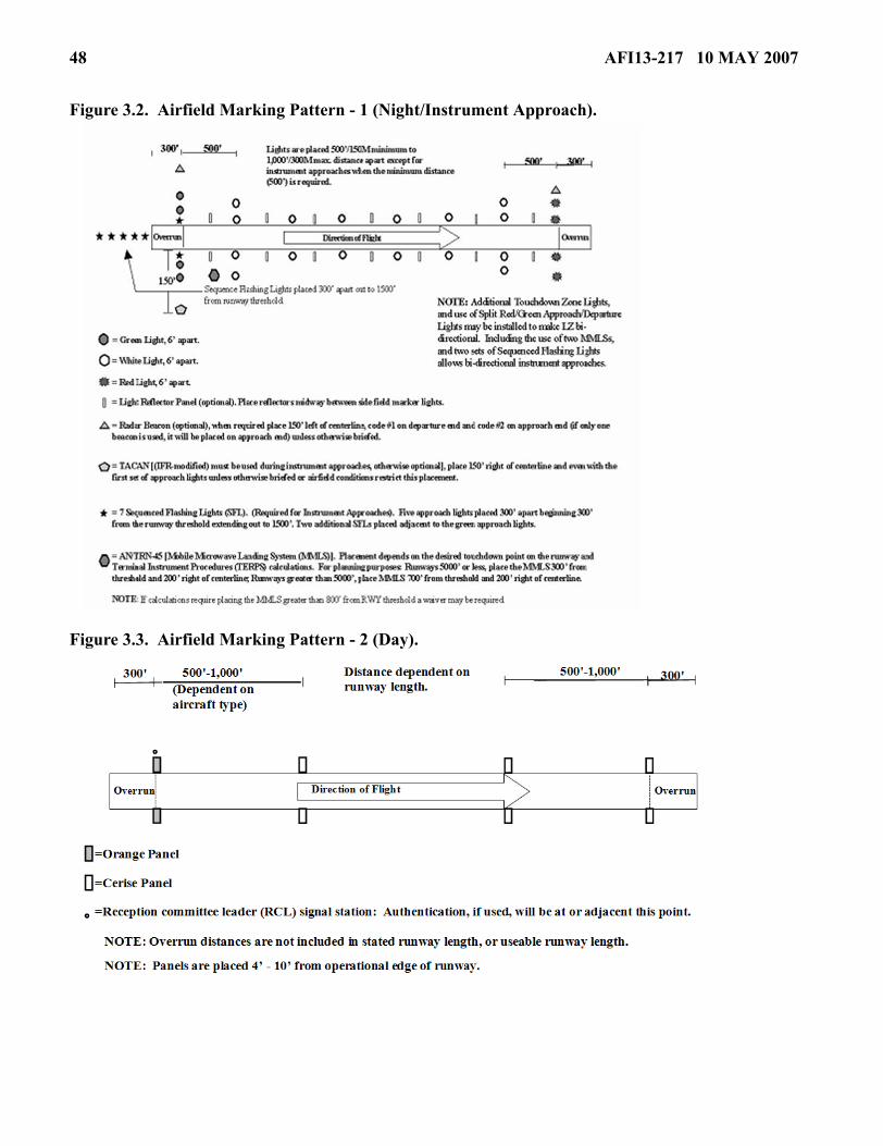
48 AFI13-217 10 MAY 2007
Figure 3.2. Airfield Marking Pattern - 1 (Night/Instrument Approach).
Figure 3.3. Airfield Marking Pattern - 2 (Day).

AFI13-217 10 MAY 2007 49
Figure 3.4. Airfield Marking Pattern - 2 (Night).
Figure 3.5. Airfield Marking Pattern - 3 (Day).

50 AFI13-217 10 MAY 2007
Figure 3.6. Airfield Marking Pattern - 3 (Night).
3.7. Emergency Signals. Standard air traffic control light signals are normally used if radio communica-tions are not established. A go around may also be signaled by using either red flares, a red light beamaimed directly at the pilot, or a radio call to the pilot. See Table 3.2.
NOTE: Emergency signals must be coordinated and thoroughly briefed. NVG equipped crews may beunable to discern colored lights, and any light signal pointed at the aircraft may blind the aircrew.
Table 3.2. Standard Air Traffic Control Light Signals.
3.8. Communications. The OG/CC or ACC will determine communications requirements. StandardFederal Aviation Administration (FAA) radio procedures will be used unless otherwise briefed. The
SIGNAL AIRCRAFT ON GROUND AIRCRAFT IN AIR Steady Green Cleared for Takeoff Clear to Land Flashing Green Clear to Taxi Return for Landing
Steady Red Stop Give way to other aircraft and continue circling
Flashing Red Taxi Clear of Runway Field unsafe-Do not land Flashing White Return to starting point N/A Alternating Red/Green Use extreme caution Use extreme caution

AFI13-217 10 MAY 2007 51
Landing Zone Controller (LZC) and Landing Zone Safety Officer (LZSO) are the only individuals autho-rized to communicate control instructions to aircraft operating near an LZ.
3.9. Terminal NAVAIDS. ST units have the capability to tactically employ and operate a variety ofNAVAIDS in support of LZ operations. The units deploy NAVAIDS, such as the TACAN, ZM, mobilemicrowave landing system (MMLS), or radar beacons as directed by the ACC. Standard NAVAID place-ment procedures are listed below; however, the tactical environment will frequently require modificationsof these standard placements.
3.9.1. TACAN. When used for instrument procedures, recommended placement is 150 feet right ofrunway centerline abeam the first set of approach lights in an area free of excessive aircraft, vehicle,and troop movements.
3.9.2. Radar Beacons. Since radar beacons transmit signals via “line-of-sight,” terrain on the LZ andalong the inbound course must be taken into consideration to allow the earliest possible acquisition.Ensure aircrews are briefed on beacon placement. For AMP-1 through AMP-3 Landings, place oneradar beacon (code 2) 150 feet left of runway centerline abeam the first set of steady lights (panels) inthe touch down zone. Place a second beacon (code 1) 150 feet left of the departure end flashing strobe.
3.10. Landing Zone Personnel.
3.10.1. Minimum Personnel. A Landing Zone Safety Officer (LZSO) is required and, depending onthe operations, a Landing Zone Controller (LZC) may also be required.
3.10.2. The LZC's primary function is to provide air traffic control services.
3.10.2.1. The LZC will be a qualified combat controller certified by the unit commander as capa-ble of performing unilateral or joint air traffic control duties. ST units are authorized to combineLZC/LZSO functions during VFR operations. When combined, LZSO skill level requirementsmust be met.
3.10.3. The LZSO will normally be a qualified E-5 or above (seven or nine skill level) combat controlNCO, special tactics officer, AMLO, or airlift aircrew officer (U-28A, C-130 or C-17 aircrew officerfor LZ operations) certified by the unit commander as capable of performing as a LZSO.
3.10.3.1. During visual flight rules (VFR) operations not requiring Air Traffic Control (ATC) ser-vices (Class G airspace), qualified Air Force Reserve Command (AFRC), Air National Guard(ANG), and AF active duty personnel designated by their commander may establish LZ markings.If the LZ is semi-prepared, they are restricted to operations on their local training LZ. These per-sonnel assume the LZSO responsibilities listed in paragraph 3.10.4.
NOTES:USAFWS Weapons Officer airlift cadre may perform LZSO duties at all approved CONUS LZs notrequiring an LZCO. These personnel assume LZSO duties and responsibilities listed in 3.10.4. providedthey have received the HQ AFSOC formal training by a 7-level combat controller or aircrew certified per-sonnel formally trained by a 7-level combat controller.
Under no circumstances are personnel who fall under this category permitted to provide aircraft with airtraffic control services.

52 AFI13-217 10 MAY 2007
3.10.3.1.1. Aircrew member certification will consist of training coordinated between the fly-ing squadrons and ST. This training will be conducted using HQ AFSOC formal lesson plans.The flying squadron commander will review/authorize unilateral single-ship missions to land-ing zones without a LZC or an operating control tower (Class G airspace).
3.10.3.1.2. Non-USAF / Non-aircrew personnel. If contingency operations require USAF useof landing zones not defined within the scope of this AFI, or under the operational control ofnon-USAF / non-aircrew personnel, a combat controller or AMLO may train allied forces per-sonnel (with ACC or DIRMOBFOR approval) to perform LZSO duties IAW paragraph 3.10.4.of this instruction using approved HQ AFSOC formal lesson plans. The instructor will providea letter certifying personnel to perform LZSO duties limited to the landing strip trained on andfor a specified duration.
3.10.3.2. Units listed in paragraph 2.17.3.2. are authorized to use qualified personnel to establishLZs supporting single-ship VMC operations that do not require air traffic control services (ClassG airspace).
NOTE: Under no circumstances are personnel who fall under this category permitted to provide aircraftwith air traffic control services.
3.10.3.2.1. Civilian contract personnel who were previously qualified as a combat controller,or were a C-130 or C-17 aircrew officer, must complete the HQ AFSOC formal lesson planand receive instruction IAW paragraph 3.10.3.1.1. before they are authorized to control land-ing zone operations. These personnel assume the LZSO responsibilities listed in paragraph3.10.4. Previously qualified combat control personnel may perform LZC functions providedtheir statement of work requires those duties, they pass a flying class II physical and meet LZCcurrency requirements outlined in AFSOCI 36-2204.
3.10.4. The LZSO represents the OG/CC or ACC as provided in mission directives and is responsiblefor the following:
3.10.4.1. Ensuring required aircraft rescue and firefighting (ARFF) coverage is at the LZ prior tobeginning airland operations, and ensures continuous contact with ARFF is maintained.
3.10.4.2. Maintaining close liaison with the using unit commander, or designated representative,during joint operations.
3.10.4.3. Observing and evaluating all factors that may adversely affect the safety and efficiencyof the operation.
3.10.4.4. Inspecting the LZ prior to use IAW paragraph 3.5., and validating the LZ meets criterialisted on the current LZ survey.
3.10.4.5. Monitoring the conditions of the landing, taxi, and parking areas, and ensuring the run-way is free of obstacles before advising aircraft they are cleared to land/takeoff at their own dis-cretion.
3.10.4.6. Ensuring LZ markings and NAVAID placement are correct and operating.
3.10.4.7. Ground handling and marshaling of aircraft.
3.10.4.8. Evaluating and reporting surface wind and meteorological phenomenon.
3.10.4.9. Ensuring the dissemination of available altimeter settings.

AFI13-217 10 MAY 2007 53
3.10.4.10. Formulating minimum safe altitudes and monitoring the deconfliction of artillery andclose air support operations.
3.10.4.11. Advising the LZC if conditions are unsafe for landing operations and ensures cancella-tion of operations is relayed to appropriate agencies.
3.10.4.12. Supervising all Air Force personnel on the LZ.
3.10.4.13. Maintaining contact with the LZC during the operation.
3.11. Rolling Friction Factor. When conducting operations on semi-prepared surfaces with C-17 air-craft, the LZC/LZSO will determine the runway friction factor IAW ETL-97-9. C-17 mission plannersoptimally require this factor a minimum of 24hrs prior to airland operations.
3.11.1. This value will be reported to each departing C-17 prior to taxi, and again prior to departure.This value will also be reported to arriving C-17 aircraft.
3.11.2. After each C-17 departure, or whenever the LZ team notices a discernable deterioration of theLZ surface, they will re-determine the rolling friction factor. During sustained operations, consider-ation to the ability to gather data must be realized. If the new factor is not feasible, then C-17 aircraftwill be given the last value noting the time it was taken and how many sorties have taken place sincethat reading.
3.12. LZ Control Point Location. The LZC locates the control point after considering pertinent factorssuch as security, runway in use, and view of the airfield and surrounding airspace. Separation of aircraftand the ability to detect hazards on or near the operating area supersede other concerns.
3.13. Aircraft Rescue and Fire Fighting Requirements. Specific requirements for ARFF are con-tained in MAJCOM (i.e., AMCI 11-208, Tanker/Airlift Operations) publications. When required, the userwill preposition suitable equipment at the LZ prior to conducting operations.
3.14. Landing Zone Review Process. The following paragraphs outline the LZ survey process fromperforming the initial groundwork to the final incorporation of the LZ into the ZAR database. Use of theZAR will expedite mission planning, enhance safety, and avoid duplication of surveys. Information in theZAR does not replace the need for a completed survey prior to conducting landing zone operations. Allcompleted surveys should be forwarded by the appropriate agencies to HQ AMC/A3DT for inclusion inthe worldwide database. LZ surveys become obsolete 5 years after date of MAJCOM approval (block 4Cof AF Form 3822) and must be resurveyed prior to use. Procedures for requesting an initial or re-surveyof an LZ are contained in paragraph 1.4.
NOTE: Other MAJCOMs and contingency AOCs may maintain their own ZAR database (if desired).However, this does not alleviate them of the responsibility to provide these surveys to HQ AMC/A3DTfor inclusion in the worldwide ZAR database, unless classification requirements dictate otherwise.
3.14.1. Combat control personnel or qualified civilians complete the AF IMT 3822, Landing ZoneSurvey (Attachment 5). Qualified civilians may be a GS employee, contractor, and/or temporarycontractor hired by DoD to perform survey specific duties. All qualified civilians will be trained IAWthe current AFSOC survey training guidance and meet AFSC 1C2X1, combat control, CFETP train-ing requirements. Training will be validated in a memorandum signed by the 720 STG/CC and trackedat the 720 OSS.

54 AFI13-217 10 MAY 2007
3.14.2. Following completion of the ground survey by combat control personnel or qualified civil-ians, the AF IMT 3822 is forwarded to the appropriate chief, wing/group tactics, or as designated bythe OG/CC, for a safety-of-flight review. The MAJCOM/A3 or ACC or their designated representa-tive is final approval authority.
3.14.2.1. Safety-of-Flight Review. A safety-of-flight review is completed by the nearest Air Forcewing/group tactics office on all LZ surveys. The purpose of a safety-of-flight review is to ensurean aircraft can safely ingress, egress and operate in the vicinity of the LZ. A safety-of-flightreview includes an in-depth chart study of the terrain features, obstructions to flight, and airspacerestrictions along the route of flight to and from an LZ. For a complete list of regional group/wingtact ics off ices see: https: / /afkm.wpafb .af .mil /ASPs/CoP/OpenCoP.asp?Fi l -ter=OO-OP-AM-40 A 1:50,000-scale chart and satellite imagery (if available) should be usedwhen available for the objective area and at least a 1:250,000-scale chart for the ingress, egressand traffic pattern. If approved by the MAJCOM, Portable Flight Planning Software (PFPS) maybe used instead of paper charts. The safety-of flight review lists all obstructions such as terrain,towers, or power lines that may affect the aircraft’s ability to achieve ingress, egress, traffic patternaltitudes and airspeeds. The safety-of-flight review will also review any prohibited areas,restricted operating zones (ROZs), noise sensitive areas, special use airspace, route of flight toavoid such areas, preferred routing, NOTAM requirements, population areas etc. Evaluate terrain/obstructions within a radius of 5nm (minimum) and 10nm (desired) from the LZ centerpoint. Highaltitude penetrations to the LZ may require evaluation of terrain/obstructions out to a 20nm radius.Evaluate likely avenues of ingress/egress along runway centerline and others as mission planningrequirements dictate arrival/departure paths. Evaluation of terrain/obstructions should include ser-vice ceiling and climb performance for the particular aircraft involved, the ability of the aircraft totake-off/fly over the LZ at low speeds and escape from the LZ using 3-engine climb out rates. Ifthese criteria cannot be met, the ingress/egress routing must be modified, altitude raised, take-off/landing directions restricted to one-way operations, or the safety-of-flight review denied.
3.14.3. The AF IMT 3822 is not valid for use until it has been reviewed and recommended for use bythe appropriate MAJCOM/A3 or the ACC. The AF IMT 3822 is then forwarded for inclusion in thelanding zone database.
3.14.4. The AF IMT 3822 documents the conditions that existed at the time the survey was accom-plished and may not account for changes to the LZ seasonal topography. The condition of the LZshould be confirmed prior to commencing operations.
Section 3B—Helicopter Landing Zone Operations
3.15. General. Helicopters require their own landing zone procedures to safely operate in areas unsuit-able for fixed-wing aircraft. HLZ surveys are required for all training and exercises and highly recom-mended as part of the normal mission planning for contingencies. HLZ surveys are not required if anothersurvey is available (ie. fixed wing LZ survey or FARP survey). The paragraphs below define the proce-dures.
3.16. Helicopter Landing Zone Selection. Helicopter landing zones (HLZ) are dependent on the air-craft type and size, and whether the HLZ will be used for takeoffs/landings or alternate insertion/extrac-tion (AIE). Selecting the HLZ location is the joint responsibility of the ACC and the supported forcecommander. JFSOCC forces determine their suitable locations from JSOACC recommendations.

AFI13-217 10 MAY 2007 55
3.16.1. Weight Bearing Capacity. HLZs are dependent on the aircraft type or size. Weight bearingcapacity is not required for helicopter operations, but care must be exercised to ensure the HLZ iscleared to prevent possible engine damage or personnel injury from flying debris due to hover opera-tions.
3.17. Helicopter Landing Zone Markings. MAJCOMs may supplement this instruction with theirunique requirements. There are no USAF requirements to mark HLZs for day or NVG use. HLZs flownto unaided at night must be clearly marked with a minimum of two overt lights that either outline or targetobstruction free areas compatible with the aircraft being used. Additionally, overt spot or landing lightsmust be available and used by the aircraft during the approach.
3.18. Helicopter Landing Zone Survey Requirements. The HLZ survey program is a group tacticsfunction or an office with an equivalent level of expertise. Group tactics must ensure surveys are con-ducted IAW the procedures below.
3.18.1. Completing the HLZ survey process involves a physical inspection of the HLZ, documentingthe information on the AF Form 4303, Helicopter Landing Zone Survey, a safety-of-flight review,and final approval. MAJCOMs will determine their own requirement for HLZ surveys for AIE train-ing. Surveys may be accomplished by the using units whose equipment or personnel are being landedor for an AIE. For exercises and joint training operations, users must ensure the survey is completedand meets the appropriate criteria for operational and safety standards. The user must conduct a phys-ical inspection of the HLZ prior to use to identify and evaluate potential hazards to personnel/equip-ment, man-made or natural structures, and ground personnel. If the survey was conducted using anyother method than GPS-derived coordinates, provide the reviewer with the raw coordinate data andthe method of conversion.
3.18.1.1. Host Nation (HN) HLZ Surveys. When conducting operations on or over a HN surveyedHLZ, a review of the HN survey will be accomplished before operations to the HLZ begin. Usersremain responsible for ground operational and safety criteria.
3.18.1.2. A 1:50,000 scale chart or less should be used when available for the objective area forthe ingress and egress (Portable Flight Planning Software (PFPS) may be used instead of papercharts if approved by the MAJCOM). The review lists all obstructions such as terrain, towers, orpower lines that may affect the helicopter’s route of flight. Also listed on the review are any pro-hibited areas, noise sensitive areas, special use airspace, route of flight to avoid such areas, pre-ferred routing, NOTAM requirements, etc. Evaluation of terrain/obstructions should consider theparticular helicopter involved, and the ability to fly over and/or land on the HLZ unless OGEhover power plus 5-percent is available. If these criteria cannot be met, the ingress must be modi-fied, or the review denied.
3.18.2. When conducting operations on a HLZ that was previously surveyed by another unit, the com-mander of the using unit is responsible for ensuring the HLZ meets the criteria for that operation. Inall cases, the using unit must accept responsibility for all personnel injuries, parachute or load dam-age, and property damage.
3.18.3. Tactical HLZ Surveys. During exercises and contingencies, when time or situations do notpermit completion of a full HLZ survey, a tactical HLZ survey may be required to meet the appropri-ate commander’s objective(s).
56 AFI13-217 10 MAY 2007
3.18.3.1. Though preferable, the use of an AF Form 4303 is not required for a tactical survey.Requests and surveys may be passed electronically. As much information as practical should beobtained and forwarded for review.
3.18.3.2. Requests for tactical surveys will be forwarded to the designated exercise/contingencyACC for final review.
3.18.3.3. When using a tactical HLZ, the rotary-wing unit assumes responsibility for helicoptersafety-of-flight.
3.19. Helicopter Landing Zone Review Process. The following paragraphs outline the HLZ reviewprocess from performing the initial groundwork to the final coordination. All completed surveys will beforwarded to the group tactics office, or an office with an equivalent level of expertise. Surveys will bereaccomplished when the user and/or provider determine changes in the ground or air aspects of the HLZdata require a new survey.
3.19.1. The HLZ surveys will be conducted during daylight by a qualified combat controller; surveyqualified rotary wing aircrew member, Chief Group Weapons and Tactics, or a qualified civilian.Qualified civilians will meet the training and documentation requirements listed in para 3.14.1.AFSPC will establish requirements in their supplement for surveying Missile Alert Facilities (MAF)and Launch Facilities. The surveyor (AF Form 4303, item 4A) performs the actual ground portion ofthe HLZ survey (i.e., measurements, coordinates, calculating size, obtaining maps and creating dia-grams) and annotates results on the AF Form 4303. The surveyor may be a member of the unit thatintends to use the HLZ, or a member of another unit may perform the ground portion of a survey ifrequested and time permits. To facilitate future use of surveyed HLZs, initial surveys will encompassthe largest area available and will not be limited by specific mission requirements. The surveyor willforward the completed survey to the group tactics office, or the OG/CC designated office, for review.Include recommended use, any deviations from HLZ standards contained in service or MAJCOMdirectives, and other pertinent remarks.
3.19.2. The reviewer, in order of preference, is the Chief, Group Tactics, Squadron Commander, orSquadron Operations Officer (AFSPC/A3 may designate the helicpter squadron commander and oper-ations officer as reviewing officials). The reviewer (AF Form 4303, item 4B) ensures the HLZ can besafely used from a flight perspective. Throughout the review process, HLZ survey packages willinclude all applicable maps, photos, charts and diagrams necessary to determine the safety and utilityof the HLZ.
3.19.3. Approval Authority (AF Form 4303, item 4C). Prior to use, surveys will be approved for airoperations by the OG/CC or appropriate ACC. This approval assures the review has been accom-plished and the HLZ is considered safe for air operations.
3.19.4. Once item 4C of AF Form 4303 is completed, the survey is ready for use. Respective grouptactics offices are the local area repositories for HLZ surveys. AFSPC/A3 will designate an office toserve as a repository for LZ surveys.
3.19.5. HLZ surveys document the conditions that existed at the time the survey was accomplished,and may not account for changes to seasonal topography. Recommended uses may be based on mini-mum requirements and should not be misconstrued to be all-inclusive (i.e., a HLZ recommended fortwo MH-53s may not be suitable for a CV-22). It is the responsibility of the flying and ground units

AFI13-217 10 MAY 2007 57
involved to ensure that any HLZ being considered for use meets the requirements for their specificoperation.
3.20. Helicopter Landing Zone Survey Updates. HLZ surveys will be updated every six months.HLZs that are not updated in the six months time period will be closed until resurveyed using the abovecriteria (does not require a new AF Form 4303). AFSPC will establish requirements in their supplementfor updating MAF and Launch Facilities. The absolute minimum to update a HLZ survey requires a qual-ified combat controller, qualified rotary wing aircrew member, or Chief Group Weapons and Tactics toresurvey the HLZ during daylight. This member must evaluate items 6 through 10 of AF Form 4303.Annotate date of update and surveyor’s initials in remarks section. A HLZ survey that has not beenupdated for 12 months is expired and a new AF Form 4303 will be accomplished.

58 AFI13-217 10 MAY 2007
Chapter 4
LC-130 SKIWAY AND SKI LANDING AREA CRITERIA
4.1. General. These procedures apply to all agencies involved in or supporting LC-130 operations andclarify Skiway and Ski Landing Area requirements.
4.2. Ski Landing Area Control Officer (SLACO). 109th Airlift Wing (ANG) develops and maintainsprocedures to train and certify SLACOs.
4.2.1. SLACOs will be designated before the deployment and will be either an experienced LC-130pilot or combat controller experienced in LC-130 ski operations. The SLACO will be at the site andexamine the results of the Ski Landing Area testing, preparation and marking. If the area meetsrequirements, and with the concurrence of the Camp Manager, the SLACO will advise the 109 AWDeployed Commander LC-130 ski landings/takeoffs may commence. A certified SLACO will remainat the Ski Landing Area during all initial LC-130 Ski operations until complete or until relieved by theDeployed Commander.
4.3. Selection of Skiway or Ski Landing Area. Agencies planning scientific research or military exer-cises must choose between construction of a Skiway or Ski Landing Area. Proposed landing locationsmust be submitted IAW paragraph 4.3.1. so they can be evaluated in terms of distance from hard surfacestaging bases, cargo requirements, meteorological conditions, number of landings and takeoffs, durationof the operation and the amount of cargo to be offloaded/onloaded. Agencies requiring landings and take-offs on sea ice must also provide information on ice depth and surface characteristics. Minimum thicknessis discussed in Table 4.1.
4.3.1. Submit proposed landing locations to 109 AW/139 AS Tactics (DOW), 1 Air National GuardRoad, Scotia, NY 12302-9752. Phone: comm 518-344-2640/2650, or DSN 344-2640/2650.
4.4. Sea Ice Depth Testing and Evaluation Criteria. Extensive research and testing of ice characteris-tics has been done by several agencies and a large body of scientific research and testing data is availableto agencies interested in ice field or sea ice operations. The following paragraphs provide simple LC-130ski operations limitations and procedures.
4.4.1. The load bearing capacity of ice sheets varies with thickness, surface temperature, and weightof the aircraft and parking time. Minimum ice thickness required for LC-130 operations is based ondata derived from US Naval Civil Engineering Lab, Technical Report R860, Study of Related Proper-ties of Floating Sea-Ice Sheets and Summary of Elastic and Visco-Elastic Analyses, and LC-130 air-craft field experience. The limits in Table 4.1. are established as minimum values for LC-130 aircraft.They may be applied up to the maximum ski landing/takeoff gross weight of 147,000 pounds. Opera-tions with ambient temperature above freezing must be evaluated and approved by the commander.

AFI13-217 10 MAY 2007 59
Table 4.1. Ice Weight Bearing Capacity.
4.4.2. Testing of sea ice depth at landing/takeoff areas should be done by drilling through the ice at500-foot intervals on alternated sides for the entire length of the landing area. Minimum depth valuesmay not include surface snow or slush. Additional drill tests should be performed weekly during con-tinuous operations or prior to resuming landings/takeoffs after a period of non-use of more than oneweek. The area should be checked regularly for signs of cracking or surface deterioration.
4.4.3. Surface evaluation of potential landing/takeoff areas is necessary to assure the area is suitablefor LC-130 ski operations. The better the natural conditions the less preparation work will be neces-sary. The best condition is a relatively smooth ice surface with 2 or more years of snow accumulationto a depth of 12 inches (minimum acceptable depth is 6 inches). Conditions to be avoided are:
4.4.3.1. Undulating or irregular ice sub-surface impacting the skis during landing or takeoff. Theundulating sub-surface may be covered with snow that would be deformed by the skis during skiruns.
4.4.3.2. Bare ice with little or no snow cover. Snow cover is required to cushion and distributeloads over the skis. Even small irregularities or cracks in bare ice can create stress points along theski that can cause damage.
4.4.3.3. Large irregularities in the snow surface (sastrugis, ridges, and humps) require extensivesurface preparation before ski operations.
4.5. Skiway Marking.
4.5.1. Skiways will be marked in accordance with Figure 4.1. These markings are intended to allowflight operations in instrument meteorological conditions. The length and width of the marked areamay vary with field elevation, snow conditions, operating gross weight, and duration of use. Mini-mum length and width is 5,000 ft x 150 ft at sea level. Length and width up to 15,000 ft x 300 ft maybe required at higher elevations. IAW paragraph 4.3.1., 109 AW will coordinate with the supportedagency to determine length and width for development of a particular Skiway. In addition to Skiwaymarkings, a cargo offload/onload area will be marked (Figure 4.2.). It may be located adjacent to theSkiway or further removed according to camp requirements. Accumulated cargo or other structuresmust not be closer than 75 feet from any skiway edges. Skiway markers are made from nylon meshand mounted on bamboo poles (Figure 4.3.).
4.5.2. Operations of a temporary nature requiring limited ski landings/takeoffs may not require anestablished Skiway. 109 AW, in coordination with the agency being supported, will determine whethera Ski Landing Area or Skiway will be established for a particular operation. Factors such as field ele-vation, density altitude and snow conditions will be considered to determine minimum length andwidth of the Ski Landing Area. A Ski Landing Area will not be less than 5,000 ft x 150 ft. Ski LandingAreas shall be marked as shown in Figure 4.4. The primary differences between Skiways and SkiLanding Areas are the absence of lead-in flags and, for a Ski Landing Area, fewer skiway flags. A
SURFACE TEMPERATURE MINIMUM ICE THICKNESS -10 deg C or less 55 inches -10 to -5 deg C 60 inches -5 to 0 deg C 85 inches

60 AFI13-217 10 MAY 2007
midpoint marker will be established by placing red flags at the halfway point (five flags for a Skiway,three flags for a Ski Landing Area).
4.6. Surface Preparation and Maintenance. The agency being supported is responsible for preparingthe surface.
4.6.1. Arctic / Antarctica (other than sea ice) operations on Open Snow, Ski Landing Areas andSki-ways will be authorized by the Deployed Commander in accordance with AFI 11-2C-130, Vol-ume 3, C-130 Operations Procedures, and this Instruction.
4.6.1.1. Dragging is required to remove surface irregularities created by wind action (sastrugis)and to promote ice crystal deformation to harden the loose surface snow. Various types of dragdevices have been successfully used.
4.6.1.2. The cargo offload/onload area (Figure 4.2.) should also be groomed to harden the surfaceprior to supporting cargo offload/onload operations.
4.6.1.3. Maintaining the Skiway or Ski Landing Area will require periodic dragging. The Skiwayor Ski Landing Area should be dragged immediately after fresh snow accumulation, windstormsor when ski landings/takeoffs have disturbed the surface. Regular inspections by the ground partyand pilot reports will determine if dragging or other maintenance action is required.
4.6.2. Glacial/Sea Ice Ski Landing Areas must be certified by a SLACO and authorized by theDeployed Commander.
4.6.2.1. Ice irregularities, often hidden by snow cover can do significant damage to skis whenstruck at any speed. An ice crack with an edge of more than 4 inches may do damage at taxi speedsas the ski bridges the crack and a stress point is applied to the ski. Surface preparation mustinclude a thorough survey of the landing area to look for ice irregularities and study snow depthsand characteristics. Any unacceptable irregularities must be removed. If the resulting surface isacceptable, ski operations can begin after appropriate marking and certification. Snow irregulari-ties may be large enough to require the entire surface to be dragged or graded to fill low areas andremove high areas. All undulating surfaces must be graded to minimize the slope and prevent skidamage. Care must be taken not to remove the entire snow surface down to bare ice because snowcushions and distributes loads during ski takeoffs and landings.
4.6.2.2. Cargo offload/onload areas and taxi routes to those areas should be groomed and markedas illustrated in Figure 4.2.
4.6.2.3. Weather and repeated ski operations can deteriorate Skiway surface conditions. Dailyinspections by the ground party and pilot reports will determine maintenance requirements. Dailydragging or grading may be required to maintain an acceptable surface. Maintenance of flags andthe cargo on/offload area are also required.
4.7. Flagging Guidance.
4.7.1. Minimum flagging for a Skiway should consist of the following (Figure 4.1.).
4.7.1.1. Lead-in Flags.
4.7.1.1.1. A set of four (4) black flags arranged to make a “plus sign” (+) at each lead-in flaglocation.

AFI13-217 10 MAY 2007 61
4.7.1.1.2. The first set of lead-in flags is located 1,000 ft from the skiway threshold along theextended skiway centerline.
4.7.1.1.3. The second set of lead-in flags will be spaced 500 ft from the first set.
4.7.1.1.4. The third set of lead-in flags will be spaced 500 ft from the second set.
4.7.1.1.5. All other sets of lead-in flags will be spaced 1,000 ft apart out to 12,000 ft from theskiway threshold to form a two-mile lead-in.
4.7.1.1.6. This spacing will require thirteen (13) sets of lead-in flags.
4.7.1.2. Skiway Flags.
4.7.1.2.1. Three (3) black flags at 400-foot intervals along the full length and on both sides ofthe skiway.
4.7.1.2.2. Five (5) red flags at the threshold, midpoint, and departure end locations on bothsides of the skiway.
4.7.1.2.3. Three (3) “2,000 ft remaining” flags (black with a white number 2) on both sides ofthe skiway at the appropriate distance remaining from each skiway departure end.
4.7.2. Minimum flagging for a Ski Landing Area should consist of the following (Figure 4.4.).
4.7.2.1. Skiway Flags.
4.7.2.1.1. Two (2) black flags along the full length of both sides of the ski landing area at500-foot intervals.
4.7.2.1.2. Three (3) red flags on both sides of the ski landing area at the threshold, midpoint,and departure end locations.
4.7.2.1.3. Two (2) “2,000 ft remaining” flags (black with a white number 2) on both sides ofthe ski landing area at the appropriate distance remaining from each departure end.

62 AFI13-217 10 MAY 2007
Figure 4.1. Skiway Marking.

AFI13-217 10 MAY 2007 63
Figure 4.2. Cargo Offload/Onload Area.

64 AFI13-217 10 MAY 2007
Figure 4.3. Typical Skiway Marker Construction.

AFI13-217 10 MAY 2007 65
Figure 4.4. Ski Landing Area Marking.
RICHARD Y. NEWTON III, Maj Gen, USAF Asst DCS, Operations, Plans & Requirements

66 AFI13-217 10 MAY 2007
Attachment 1
GLOSSARY OF REFERENCES AND SUPPORTING INFORMATION
References
AFPD 13-2, Air Traffic Control, Airspace, Airfield, and Range Management, 7 January 1994
AFI 11-202 Volume 3, General Flight Rules, 5 April 3006
AFI 11-231, Computed Air Release Point Procedures, 31 August 2005
AFI 11-2C-130, Volume 3, C-130 Operations Procedures, 14 March 2006
AFI 11-410, Personnel Parachute Operations, 20 May 2004
AFI 13-210(I), Joint Airdrop Inspection Records, Malfunction Investigations, and Activity Reporting, 1May 1998
AFI 32-7061, The Environmental Impact Analysis Process, 12 March 2003
AFI 91-204, Safety Investigations and Reports, 14 February 2006
AFJPAM 32-8013, Volume II (FM 5-430-00-2), Planning and Design of Roads, Airfields and Heliports inthe Theater of Operations - Airfield and Heliport Design, 19 August 2004
AFMAN 11-411(I), Military Free-Fall Parachuting, 6 April 2005
AFMAN 11-420(I), Static Line Parachuting Techniques and Training, 23 September 2003
AFMAN 37-123, Management of Records, 31 August 1994
AIR STD 44/35G, Drop Zones and Extraction Zones: Criteria, Markings and Information Check Lists, 30April 1990
AIR STD 44/37C, Criteria for Selection and Marking of Landing Zones for Fixed Wing Aircraft, 23 July1987
AMCI 11-208, Tanker/Airlift Operations, 1 June 2000
AMCI 13-101, Air Mobility Liaison Officers, 30 March 2003
ETL 04-7, C-130 and C-17 Contingency and Training Airfield Dimensional Criteria, 29 March 2004
ETL 02-19, Airfield Pavement Evaluation, Standards and Procedures, 11 December 2002
STANAG 3146, Planning Procedures for Tactical Air Transport Operations, 10 July 1995
STANAG 3345, Data/Forms for Planning Air Movements, 28 February 1989
STANAG 3570, Drop Zones and Extraction Zones, and 3601, Criteria for Selection and Marking ofLanding Zones for Fixed-Wing Transport Aircraft, 28 February 1989
Vaudrey K.D., U.S. Naval Civil Engineering Lab, Technical Report R860, Ice Engineering: Study ofRelated Properties of Floating Sea-Ice Sheets and Summary of Elastic and Visco-Elastic Analyses, 1977

AFI13-217 10 MAY 2007 67
Abbreviations and Acronyms
ACC—Air Component Commander
AFCESA—Air Force Civil Engineer Support Agency
AFRIMS—Air Force Records Information Management System
AFWA—Air Force Weather Agency
AGL—Above Ground Level
AGU—Airborne Guidance Unit
AIE—Alternate Insertion/Extraction
AMD—Air Mobility Division
AMLO—Air Mobility Liaison Officer
AMP—Airfield Marking Pattern
AOC—Air Operations Center
ARC—Advanced Rescue Craft
ARFF—Aircraft Rescue and Fire Fighting
ASIC—Air and Space Interoperability Council [formerly known as the Air Standardization CoordinatingCommittee (ASCC)]
ATC—Air Traffic Control
AWADS—Adverse Weather Aerial Delivery System
CANLS—Contingency Airfield Night Lighting System
CARP—Computed Air Release Point
CCT—Combat Control Team (See Special Tactics)
CDA—Collateral Damage Assessment
CDS—Container Delivery System
COMAFSOF—Commander, Air Force Special Operations Forces
COMJSOTF—Commander, Joint Special Operations Task Force
CRRC—Combat Rubber Raiding Craft
CRG—Contingency Response Group
CRL—Container Ramp Load
CRO—Combat Rescue Officer
CRS—Container Release System
DIRMOBFOR-Air—Director Of Mobility Forces
DRAS—Dual Row Airdrop System
DZ—Drop Zone

68 AFI13-217 10 MAY 2007
DZC—Drop Zone Controller
DZSO—Drop Zone Safety Officer
DZST—Drop Zone Support Team
DZSTL—Drop Zone Support Team Leader
ETL—Engineering Technical Letter
FAA—Federal Aviation Administration
FARP—Forward Arming and Refueling Point
FOM—Figure of Merit
GAR-I—Ground-To-Air Responder/Interrogator
GMRS—Ground Marked Release System
GPS—Global Positioning System
GFR—General Flight Rules
GRADS—Ground Radar Delivery System
HAARS—High Altitude Airdrop Resupply System
HAHO—High Altitude High Opening Parachute Technique
HALO—High Altitude Low Opening Parachute Technique
HARP—High Altitude Release Point
HE—Heavy Equipment
HLZ—Helicopter Landing Zone
HN—Host Nation
HSLLADS—High Speed Low Level Aerial Delivery System
HVCDS—High Velocity Container Delivery System
ICAO—International Civil Aviation Organization
IFR—Instrument Flight Rules
I-CDS—Improved-Container Delivery System
IMC—Instrument Meteorological Conditions
JFACC—Joint Force Air Component Commander
JFSOCC—Joint Force Special Operations Component Commander
JMD—Jumpmaster Directed
JPADS—Joint Precision Airdrop System
JSOACC—Joint Special Operations Air Component Commander
LAR—Launch Acceptability Region

AFI13-217 10 MAY 2007 69
LCADS—Low Cost Aerial Delivery System
LV—Low Velocity Container Delivery System
LZ—Landing Zone
LZC—Landing Zone Controller
LZSO—Landing Zone Safety Officer
MAF—Missile Alert Facility
MAAS—Mobile Aircraft Arresting System
MDS—Mission Design Series
MEW—Mean Effective Wind
MGRS—Military Grid Reference System
MMLS—Mobile Microwave Landing System
MOA—Military Operations Area
MPI—Multiple Points of Impact
MSL—Mean Sea Level
NOTAM—Notice To Airmen
NVG—Night Vision Goggle
OPCON—Operational Control
PADS-MP—Precision Airdrop System-Mission Planner
PFPS—Portable Flight Planning Software
PI—Point(s) Of Impact
RAM—Raised Angle Marker
RCL—Reception Committee Leader
RDS—Records Disposition Schedule
ROZ—Restricted Operating Zones
RPI—Random Points of Impact
SATB—Standard Airdrop Training Bundle
SKE—Station Keeping Equipment
SLACO—Skiway Landing Area Control Officer
SOLL—Special Operations Low Level ST—Special Tactics
STO—Special Tactics Officer
STS—Special Tactics Squadron
STANAG—Standardization Agreement (NATO)

70 AFI13-217 10 MAY 2007
TACAN—Tactical Air Navigation
TACP—Tactical Air Control Party
TOT—Time On/Over Target
VIRS—Verbally Initiated Release System
VFR—Visual Flight Rules
VMC—Visual Meteorological Conditions
WDI—Wind Drift Indicator
ZAR—Zone Availability Report
ZM—Zone Marker
Terms
Air Component Commander—The Commander Air Force Forces or Joint Force Air ComponentCommander; Joint Force Special Operations Component Commander or Joint Special Operations AirComponent Commander.
Airlift Coordination Cell—A cell within the air operations center, which plans, coordinates, managesand executes theater airlift operations in the area of responsibility or joint operations area. Normallyconsists of an airlift plans branch, an airlift operations branch, and an airlift logistics branch. (Joint Pub1-02)
Air Mobility Element—The air mobility element is an extension of the Air Mobility Command TankerAirlift Control Center deployed to a theater when requested by the geographic combatant commander. Itcoordinates strategic airlift operations with the theater airlift management system and collocates with theair operations center whenever possible. (Joint Pub 1-02)
Air Mobility Liaison Officer—An air mobility expert permanently assigned to an Army/Marineinstallation to support a specific Army/Marine ground maneuver unit.
Airfield Marking Pattern—A system of designations that differentiate between the various types ofairfield markings.
Class D Airspace—Category of controlled airspace, which generally consists of the area from the surfaceto 2,500 feet above ground level surrounding airports with an operational tower. Separation services areprovided to visual flight rules aircraft on a workload-permitting basis.
Class G Airspace—Class G airspace (uncontrolled) is that portion of the airspace that has not beendesignated as Class A, Class B, Class D, or Class E airspace.
Direct Air Delivery—The strategic air movement of cargo or personnel from an airlift point ofembarkation to a point as close as practicable to the user’s specified final destination, thereby minimizingtransshipment requirements. Direct air delivery eliminates the traditional Air Force two-step strategic andtheater airlift transshipment mission mix.
Director of Mobility Forces—The Director of Mobility Forces will normally be a senior officer who isfamiliar with the area of responsibility or joint operations area and possesses an extensive background inairlift operations. When established, the Director of Mobility Forces serves as the designated agent for allairlift issues in the area of responsibility or joint operations area, and for other duties as directed. The

AFI13-217 10 MAY 2007 71
Director of Mobility Forces exercises coordinating authority between the airlift coordination cell, the airmobility element, the Tanker Airlift Control Center, the joint movement center, and the air operationscenter in order to expedite the resolution of airlift problems. The Director of Mobility Forces may besourced from the theater’s organizations, United States Transportation Command, or United States JointForces Command.
Drop Zone Controller—Qualified individual in charge of a drop zone operation who represents theappropriate commander as provided in the mission directive.
Drop Zone Safety Officer—The appointed representative of the supported forces commander who isresponsible for the safe operation of the drop zone. Specific duties and responsibilities vary according tothe using airborne unit's standard operating procedures.
Drop Zone Support Team—Qualified U.S. Army/Marine Corps team responsible for supporting dropzone operations in accordance with this publication and memorandum of agreement.
Drop Zone Support Team Leader—Individual in charge of U.S. Army/Marine Corps drop zone supportteam leader.
Ground Marked Release System—A procedure used by ground forces to determine and mark therelease point for an airdrop.
Helicopter Landing Zone—A specified ground area for landing helicopters to embark or disembarktroops and/or cargo. A landing zone may contain one or more landing sites.
Joint Force Air Component Commander—The commander within a unified command, subordinateunified command, or joint task force responsible to the establishing commander for makingrecommendations on the proper employment of assigned, attached, and/or made available for tasking airforces; planning and coordinating air operations; or accomplishing such operational missions as may beassigned. The air component commander is given the authority necessary to accomplish missions andtasks assigned by the establishing commander.
Joint Force Special Operations Component Commander—The commander w i th in a un i f i edcommand, subordinate unified command, or joint task force responsible to the establishing commanderfor making recommendations on the proper employment of assigned, attached, and/or made available fortasking special operations forces and assets; planning and coordinating special operations; oraccomplishing such special operational missions as may be assigned. The joint force special operationscomponent commander is given the authority necessary to accomplish missions and tasks assigned by theestablishing commander.
Joint Special Operations Air Component Commander—The commander within the joint forcespecial operations command responsible for planning and executing joint special air operations and forcoordinating and deconflicting such operations with conventional nonspecial operations air activities. Thejoint special air operations component commander normally will be the commander with thepreponderance of assets and/or greatest ability to plan, coordinate, allocate, task, control, and support theassigned joint special operations aviation assets. The joint special operations air component commandermay be directly subordinate to the joint force special operations component commander or to anynon-special operations component or joint force commander as directed.
Landing Zone—A prepared or semi-prepared (unpaved) airfield used to conduct operations in an airfieldenvironment similar to forward operating locations. Landing Zone runways are typically shorter andnarrower than standard runways. The amount of engineering effort required to develop a semi-prepared

72 AFI13-217 10 MAY 2007
Landing Zone depends on the planned operation, the service life needed to support these operations, andthe existing soil and weather conditions. Semi-prepared construction/maintenance preparations mayrange from those sufficient for limited use to those required for continuous routine operations. Options forsurface preparation may include stabilization, addition of an aggregate course, compaction of in-placesoils, or matting. Since training airfields are constructed for long-term operations, semi-prepared surfacestructural requirements are more stringent than for contingency airfields.
Landing Zone Controller—Individual performing air traffic control duties during landing zoneoperations.
Landing Zone Safety Officer—Qualified combat controller, officer aircrew, or qualified civiliancontractor personnel in charge of the landing zone operation.
Mean Effective Wind—A theoretical wind of constant velocity and direction, extending from the surfaceto a predetermined altitude above the ground.
Military Free Fall—An employment concept encompassing both high altitude low opening and highaltitude high opening techniques of parachuting.
Military Grid Reference System—The Military Grid Reference System is designed for use with theUniversal Transverse Mercator and Universal Polar Stereographic grids.
Night—The time between the end of evening civil twilight and the beginning of morning civil twilight, aspublished in the American Air Almanac, converted to local time. (ref AFI 11-202, Volume 3, GeneralFlight Rules)
Obstruction (or Obstacle)—A natural or man-made object that violates airfield or heliport clearances,or projects into imaginary airspace surfaces.
Operational Control—Command authority that may be exercised by commanders at any echelon at orbelow the level of combatant command. Operational control is inherent in combatant command(command authority) and may be delegated within the command. When forces are transferred betweencombatant commands, the command relationship the gaining commander will exercise (and the losingcommander will relinquish) over these forces must be specified by the Secretary of Defense. Operationalcontrol is the authority to perform those functions of command over subordinate forces involvingorganizing and employing commands and forces, assigning tasks, designating objectives, and givingauthoritative direction necessary to accomplish the mission. Operational control includes authoritativedirection over all aspects of military operations and joint training necessary to accomplish missionsassigned to the command. Operational control should be exercised through the commanders ofsubordinate organizations. Normally this authority is exercised through subordinate joint forcecommanders and Service and/or functional component commanders. Operational control normallyprovides full authority to organize commands and forces and to employ those forces as the commander inoperational control considers necessary to accomplish assigned missions; it does not, in and of itself,include authoritative direction for logistics or matters of administration, discipline, internal organization,or unit training.
Point of Impact—The point on the drop zone where the first parachutist or airdropped cargo item landsor is expected to land.
Raised Angle Marker—A device used to mark the point of impact during airdrops. A triangular shapedmarker constructed of bright orange material, six feet wide at the base (minimum) and six feet high(minimum), displayed at a 60-degree angle into the direction of flight.

AFI13-217 10 MAY 2007 73
Ram Air Parachute System—US Army equivalent of a High Glide Ratio Parachute.
Release Point—The point over the drop zone where personnel or equipment should exit the drop aircraft.
Safety Zone—A distance established by agreement between the air mission commander and thesupported forces’ commander subtracted from the DZ trailing edge to reduce the potential for off-DZdrops. For peacetime personnel airdrops, the safety zone will never be less than 200 yards. Do notcompute safety zone distances for airdrops supporting unconventional warfare forces as defined by theJoint Strategic Capabilities Plane Annex E, or high altitude low opening/high altitude high openingairdrops.
Ski Landing Area—A designated area for LC-130 ski operations not meeting the criteria for a Skiway,but marked and maintained in accordance with this instruction
Skiway—A designated area for LC-130 ski operations marked and maintained in accordance with thisinstruction. Skiways must have a published instrument or visual approach procedure and be located neara surface camp with support facilities to include weather reporting, shelter, first aid, food,communications and grooming on a continual basis.
Skiway Landing Area Control Officer—An experienced LC-130 pilot or combat controllerexperienced in LC-130 ski operations responsible for certifying a Skiway Landing Area.
Station Keeping Equipment—An aircraft avionics system used to maintain formation position ininstrument meteorological conditions. When used in conjunction with an adverse aerial delivery systemlead aircraft, instrument meteorological conditions airdrops are possible.
Special Operations Forces—Those active and reserve component forces of the Military Servicesdesignated by the Secretary of Defense and specifically organized, trained, and equipped to conduct andsupport special operations.
Special Operations Low Level—C-17 qualified aircrews that support special operations usingnon-standard procedures and criteria, including operations using night vision goggles. Air MobilityCommand provides night vision goggle trained C-130 crews capable of using procedures similar tospecial operations low-level aircrew.
Special Tactics Team—United States Air Force special operations consisting of combat control,pararescue, and combat weather personnel who are organized, trained, and equipped to establish andcontrol the air-ground interface at an airhead in the objective area. Functions include assault zonereconnaissance and surveillance, establishment, and terminal control; combat search and rescue; combatcasualty care and evacuation staging; special operations terminal attack; and tactical weather observationsand forecasting.
Tactical Air Control Party—A subordinate operational component of a tactical air control systemdesigned to provide air liaison to land forces and for the control of aircraft.
Trailing Edge of a Drop Zone—Represents the imaginary line extending between the left and right rearcorners of a surveyed drop zone.
Unilateral—Describes an Air Force only operation. A unilateral mission will not be considered a jointoperation merely because the parachutists or loads are from another service. Example: an Air Forcereserve airlift unit conducting training airdrop missions using Army paratroopers or when Armyparatroopers jump with Air Force personnel on an Air Force unit's operation.

74 AFI13-217 10 MAY 2007
Verbally Initiated Release System—A method of positioning aircraft for airdrop by verbal instructionfrom the Drop Zone Controller.
Visual Meteorological Conditions—Weather conditions where visual flight rules apply; expressed interms of visibility, ceiling height, and aircraft clearance from clouds along the path of flight. When thesecriteria do not exist, instrument meteorological conditions prevail and instrument flight rules must befollowed.
Wind Drift Indicator—A 5 to 6 foot length of paper (approximately).
Zone Marker—An electronic NAVAID used by specially equipped aircraft to aid in positioning over thelanding zone, drop zone, or release point.

AFI13-217 10 MAY 2007 75
Attachment 2
WIND/SEA STATE PREDICTION CHART
A2.1. Wind/Sea State Observation Chart. Use Table A2.1. to determine the sea state for water DZ air-drops.
Table A2.1. Wind/Sea State Observation Chart.
Wind Velocity (Knots)
InternationalDescription
Wind Force (Beaufort)
Average Wave Height (Feet) Sea Indications Sea State
<1 Calm 0 0 Like mirror. 0
1 - 3 Light Air 1 0.05 Ripples with appearance of scales 0
4 - 6 Light Breeze 2 0.18 Small wavelets; crests have glassy appearance but do not break.
1
7 - 10 Gentle Breeze 3 0.6 Large wavelets; crests begin to break; scattered whitecaps. 2
11 - 16 Moderate 4 2.0 Small waves, becoming longer. Fairly frequent whitecaps
3
17 - 21 Fresh 5 4.3 Moderate waves, taking a pronounced long form; many whitecaps.
4
22 -27 Strong 6 8.2 Large waves begin to form; white foam crests more extensive; some spray.
5
28 - 33 Near Gale 7 14
Sea heaps up, white foam from breaking waves blown in
streaks along direction of waves.
6
34 - 40 Gale 8 30
Moderately high waves of greater length; crests break
into spindrift; foam blown in well marked streaks in
direction of wind.
7
41 - 47 Strong Gale 9 36 High waves. Dense streaks of foam; sea begins to roll; spray
affects visibility. 8

76 AFI13-217 10 MAY 2007
48 - 55 Storm 10 52
Very high waves with overhanging crests; foam in great patches blown in dense white streaks. Whole surface of the sea takes on a white
appearance. Visibility- affected.
9
56 - 63 Violent Storm 11 64
Exceptionally high waves (64 feet). Sea is covered with long white patches of foam Edges of wave crests are blown into
froth. Visibility seriously affected.
9.1
64 - 71 Hurricane 12 80 (est.) Air filled with foam (80+feet).
Sea is white. Visibility very seriously affected.
9.2
Wind Velocity (Knots)
InternationalDescription
Wind Force (Beaufort)
Average Wave Height (Feet) Sea Indications Sea State

AFI13-217 10 MAY 2007 77
Attachment 3
STANDARD/METRIC CONVERSION CHART
A3.1. Standard/Metric Conversion Chart. Use Table A3.1. for standard conversions.
Table A3.1. Standard/Metric Conversion Chart. STANDARD/METRIC CONVERSION CHART
Factors for Conversion of Units To convert A to B, multiply A by C. To convert B to A, multiply B by D.
UNIT A LENGTH UNIT C UNIT D UNIT B Statute Miles 5,280.0 0.0001894 Feet Statute Miles 1.609 0.6214 Kilometers Nautical Miles 1.1516 0.8684 Miles Meters 3.281 0.3048 Feet Kilometers 3,281.0 0.0003048 Feet Yards 3.0 0.33333 Feet Inches 2.540 0.3937 Centimeters Feet 0.1667 6.0 Fathoms
VELOCITIES Miles Per Hour (Statute) 1.467 0.6818 Ft. Per Second Meters Per Second 3.281 0.3048 Ft. Per Second Meters Per Second 2.237 0.4470 Miles Per Hr. (Statute) Yards/Second 2.355 0.4246 Knots
WEIGHT Ounces 0.0625 16.0 Pounds Pounds 7000.0 0.0001429 Grains Kilograms 2.205 0.4536 Pounds Short Tons 2000.0 0.0005 Pounds Short Tons 0.91 1.0989 Long Tons Long Tons 1120.0 0.8729 Short Tons
ANGULAR MEASURE Circle 360.0 Degrees Degrees 60.0 0.1667 Minutes Degrees 17.8 0.056 Mils Mils 3.27 0.296 Minutes Minutes 60.0 0.01667 Seconds TEMPERATURE CONVERSION To convert Fahrenheit to Centigrade, subtract 32 degrees and multi ply by 5, then divide by 9. To convert Centigrade to Fahrenheit, multiply by 9, divide by 5, and add 32 degrees.

78 AFI13-217 10 MAY 2007
Attachment 4
GUIDANCE CONCERNING AF IMT 3823, DROP ZONE SURVEY
A4.1. AF IMT 3823 , Drop Zone Survey. Use these instructions to complete AF IMT 3823 . All blocksrequire an entry including “N/A” if non-applicable.
A4.1.1. Block 1.
A4.1.1.1. Block 1A. Enter DZ name.
A4.1.1.2. Block 1B. If the survey will be submitted to HQ AMC/A3DT for inclusion in the ZARdatabase, then leave blank. If the survey is for local use then the wing/group tactics office shouldfill in.
A4.1.2. Block 2.
A4.1.2.1. Block 2A. Enter the Country where the DZ is located.
A4.1.2.2. Block 2B. Enter the state, province, territory, etc.
A4.1.3. Block 3. Enter map series, sheet number, edition, and date of map used.
A4.1.4. Block 4.
A4.1.4.1. Blocks 4A1 through 4A4. Enter the date the original survey was conducted, surveyor’sname, grade, telephone number, and unit of assignment (include base and state). The surveyor willsign above their typed name.
A4.1.4.2. Block 4B. The surveyor will fill out this item. Enter approval or disapproval symbol foreach drop category by using the letter “A” for approved, and the letter “D” for disapproved. Leaveno blank spaces under the preprinted categories. The blank column is for additional specialapprovals.
A4.1.4.3. Block 4C. The ground operations approval authority will verify and sign.
A4.1.4.4. Block 4D. A safety-of-flight review is completed by the chief, wing/group tactics, or asassigned by the OG/CC or equivalent, on all DZ surveys. Safety-of-flight reviewer’s signaturegives authority for the aircraft to conduct operations over the DZ.
A4.1.4.5. Block 4E. Once this block is signed, the DZ is ready for use. Signing authority is theOG/CC or the ACC.
A4.1.4.5.1. If operational requirements dictate, forward the survey to HQ AMC/A3DT, 402Scott Drive, Unit 3A1, Scott AFB, IL 62225-5302, to maintain the most current data in theZAR database.
A4.1.4.5.2. Group Tactics offices are the local area repositories for DZ surveys.
A4.1.5. Block 5.
A4.1.5.1. Blocks 5A through 5E. Enter the controlling agency responsible for scheduling the DZ.If the DZ is within a controlled or monitored area, enter the range control data for that location. Ifthe DZ is not located on government owned property. It may be necessary to obtain a Land UseAgreement (LUA) or Memorandum of Understanding (MOU). This is the responsibility of the

AFI13-217 10 MAY 2007 79
requesting unit. Check the block that applies and attach a copy of memorandum if applicable. Ifthe DZ is within a controlled area, enter the range control data needed for that location.
A4.1.6. Block 6.
A4.1.6.1. Block 6A through 6C. Enter the DZ dimensions using yards and meters. Enter the DZradius for a circular DZ.
A4.1.6.2. Blocks 6D through 6F. Enter the distance from the leading edge of the DZ to each pointof impact using yards and meters.
A4.1.7. Blocks 7A through 7D. Enter the primary DZ axis in Magnetic, Grid, and True North, andinclude Source and Date of variation data (ensure date of variation data is most current available). Usethe current year when obtaining the information from a GPS. If DZ is circular, enter N/A. List appli-cable DZ axis restrictions in remarks.
A4.1.8. Block 8A through 8D. Enter the elevation in mean sea level (MSL) for each point of impactas well as the highest point on the DZ.
A4.1.9. Block 9.
A4.1.9.1. Block 9A. Enter the spheroid used in computing coordinates for the DZ. This informa-tion can be found on the map legend. If you use the GPS in WGS-84, then enter the ellipsoid(WGS-84) in this block (recommend using WGS-84 to max extent possible).
A4.1.9.2. Block 9B. Enter the datum used in coordinate computation. This information is in thelegend information on the map. If the GPS is used, enter WGS-84 (recommend using WGS-84 tomax extent possible).
A4.1.9.3. Blocks 9C through 9E. Enter grid zone, Easting, and Northing obtained from the map.
A4.1.9.4. Block 9F. Place an “X” in the appropriate block.
A4.1.9.5. Block 9G. Enter the grid zone designator, grid square identifier, and the ten-digit MGRScoordinates. Include a short verbal description of an easily recognized point on or near the DZ(i.e., road intersection, benchmark, pond, etc.) that can be used by the DZ party to find the PIs.Include a distance and azimuth from this point to the nearest PI. Continue the Point of Originremarks in the Remarks section of the form if necessary.
A4.1.9.6. Block 9H. Enter the ten-digit MGRS coordinates in local datum and spheroid and theWGS 84 latitude/longitude coordinates to the nearest one-thousandth minute for each indicatedpoint.
A4.1.9.7. Block 9I. Enter the ten-digit MGRS coordinates in local datum and spheroid and theWGS 84 latitude/longitude coordinates to the nearest one-thousandth minute for each corner ofthe DZ.
A4.1.10. Block 10. Provide a legible sketch or CAD drawing of the DZ including all obstacles orprominent features located within the DZ boundaries. Include an arrow indicating magnetic north toassist in sketch orientation. Enter DZ name in space indicated.
A4.1.11. Block 11. Include any pertinent comments regarding operations on the DZ. Also include anystatements concerning safety in the DZ area (i.e., hazards, towers, etc.). Annotate all charted orobserved bodies of water and power lines within 1,000 meters of the DZ boundaries.

80 AFI13-217 10 MAY 2007
A4.1.12. Block 12. Indicate in the appropriate section whether photographs of the DZ and approachesare available and whether a low level route is associated with the DZ. Individual completing thesafety-of-flight review should know this information and will mark accordingly.
NOTE: When performing a safety-of-flight review on a foreign DZ, as much information as possibleshould be filled in on the AF IMT 3823 . At a minimum, the following items must be filled in: Items 4D,6A, 6B, 7, 9A-F, and 9H. A copy of the foreign DZ should be attached to the safety-of-flight review.

AFI13-217 10 MAY 2007 81
Attachment 5
GUIDANCE CONCERNING AF IMT 3822, LANDING ZONE SURVEY
A5.1. AF IMT 3822 . Use these instructions to complete the AF IMT 3822 . All blocks require an entryincluding “N/A” if non-applicable.
A5.1.1. Block 1.
A5.1.1.1. Block 1A. Enter LZ name.
A5.1.1.2. Block 1B. If the survey will be submitted to HQ AMC/A3DT for inclusion in the ZARdatabase, then leave blank. If the survey is for local use then the group tactics office should fill in.
A5.1.2. Block 2.
A5.1.2.1. Block 2A. Enter the Country where the LZ is located.
A5.1.2.2. Block 2B. Enter the state, province, territory, etc.
A5.1.3. Block 3. Enter map series, sheet number, edition, and date of map used.
A5.1.4. Block 4.
A5.1.4.1. Block 4A. Enter the date the original survey was conducted, and surveyor’s name,grade, telephone number, and unit of assignment. The surveyor will sign on top of their typedname.
A5.1.4.2. Block 4B. Enter the date the survey was reviewed, reviewer's name, grade, telephonenumber, unit and location, and signature. The reviewer is the chief, group tactics, or as designatedby the OG/CC.
A5.1.4.3. Block 4C. Enter the date the survey was approved, or disapproved, and approver’sname, grade, telephone number, unit of assignment, and signature. The approval authority is theMAJCOM/DO or ACC.
A5.1.4.3.1. If operational requirements dictate, forward the survey to HQ AMC/A3DT, 402Scott Drive, Unit 3A1, Scott AFB, IL 62225-5302, to maintain the most current data in theZAR database.
A5.1.4.3.2. Group Tactics offices are the local area repositories for LZ surveys.
A5.1.5. Block 5. Enter the controlling agency responsible for scheduling the LZ. If the LZ is within acontrolled or monitored area, enter the range control data for that location. If the LZ is not located ongovernment owned property. It may be necessary to obtain a Land Use Agreement (LUA) or Memo-randum of Understanding (MOU). This is the responsibility of the requesting unit. If the LZ is withina controlled area, enter the range control data needed for that location.
A5.1.6. Block 6. Self-explanatory. Unit of measure is feet.
A5.1.7. Blocks 7A through 7D. Enter the primary LZ run-in heading in Magnetic, Grid, and TrueNorth, and include Source and Date of variation data. Use the current year when obtaining the infor-mation from a GPS (ensure date of variation data is most current available).
A5.1.8. Block 8A through 8C. Enter the elevation in mean sea level (MSL) for each point.

82 AFI13-217 10 MAY 2007
A5.1.9. Block 9.
A5.1.9.1. Block 9A. Enter the spheroid or ellipsoid and datum (e.g., Clark 1866, NAD1927) useto compute latitude and longitude. If you use the GPS in WGS-84, then enter the ellipsoid(WGS-84) in this block (recommend using WGS-84 to max extent possible).
A5.1.9.2. Block 9B. Place an “X” in the appropriate block.
A5.1.9.3. Block 9C through 9E. Enter grid zone, Easting, and Northing obtained from the map.
A5.1.9.4. Block 9F. Enter the grid zone designator, grid square identifier, and the ten-digit MGRScoordinates in local datum and spheroid and the WGS-84 latitude and longitude to the nearestone-thousandth minute for the LZ center point, runway approach end, and departure end.
A5.1.9.5. Block 9G and 9H. Enter the ten-digit MGRS coordinates in local datum and spheroidand the WGS 84 latitude and longitude to the nearest one-thousandth minute for the LZ centerpoint, runway approach end, and departure end.
A5.1.10. Block 10.
A5.1.10.1. Blocks 10A. Enter the type of LZ surface (e.g., clay, asphalt, etc.).
A5.1.10.2. Block 10B. Enter the soil strength profile. CBR samples should be taken to a minimumdepth of 24-inches for the C-130 and 36-inches for the C-17. Indicate the thickness and strength ofeach layer (See ETL 02-19, Airfield Pavement Evaluation, Standards and Procedures). http://www.afcesa.af.mil/library/etl.asp?Category=Engineering%20Technical%20Letters
A5.1.11. Block 11. Use runway designator noted in item 7A for 11A and 11B
A5.1.11.1. Block 11A. Enter the glideslope ratio used to determine obstacle clearance in theapproach and departure zones.
A5.1.11.2. Block 11B. Enter the percentage of slope for the longitudinal gradient on the LZ. Use“+” for upslope and “-” for downslope.
A5.1.12. Block 12.
A5.1.12.1. Blocks 12A – 12H. Enter percentage of slope for the cross section gradient areaslisted. Use “+” for upslope and “-” for downslope.
A5.1.12.2. Block 12I. Enter any obstacle penetrations.
A5.1.13. Block 13. Provide a legible sketch or CAD drawing of the LZ including all obstacles,obstructions, and prominent features located within the LZ boundaries. Annotate the distance theseitems are from the LZ in the remarks section or depict on the LZ sketch. Include an arrow indicatingmagnetic north.
A5.1.14. Block 14. Include any pertinent comments regarding operations on the LZ to includedetailed and specific remarks indicating abnormalities such as loose soil on the surface level and pen-etrating depth to the hard layer below. Also include any statements concerning safety in the LZ area(i.e., hazards, towers, etc.).
A5.1.15. Block 15. Indicate in the appropriate section whether photographs of the LZ are availableand whether a low level route is associated with the LZ. Individual completing the safety-of-flightreview should know this information and will mark accordingly.

AFI13-217 10 MAY 2007 83
Attachment 6
GUIDANCE CONCERNING AF FORM 4303, HELICOPTER LANDING ZONE SURVEY
A6.1. AF Form 4303, Helicopter Landing Zone (HLZ) Survey . Use the instructions listed below tocomplete AF Form 4303. All blocks require an entry, including “N/A” if non-applicable.
A6.1.1. Block 1.
A6.1.1.1. Block 1A. Enter HLZ name.
A6.1.1.2. Block 1B. If the survey will be submitted to HQ AMC/A3DT for inclusion in the ZARdatabase, then leave blank. If the survey is for local use then the group tactics office should fill in(or to the office designated by the AFSPC/A3)
A6.1.2. Block 2.
A6.1.2.1. Block 2A. Enter the Country where the LZ is located.
A6.1.2.2. Block 2B. Enter the state, province, territory, etc.
A6.1.3. Block 3. Enter the map series, sheet number, edition, and date of map used.
A6.1.4. Block 4.
A6.1.4.1. Block 4A. Enter the date the original survey was conducted, and surveyor’s name,grade, telephone number, and unit of assignment. The surveyor will sign above their typed name.
A6.1.4.2. Block 4B. Enter the date the survey was reviewed, reviewer's name, grade, telephonenumber, unit and location, and signature. The reviewer, in order of preference, is the chief, grouptactics, squadron commander, or squadron operations officer (or to the office designated by theAFSPC/A3).
A6.1.4.3. Block 4C. Enter the date the survey was approved, or disapproved, and approver’sname, grade, telephone number, unit of assignment, and signature. The approval authority is theOG/CC or ACC.
A6.1.5. Blocks 5A and 5B. Enter the controlling agency responsible for scheduling the HLZ. If theHLZ is within a controlled or monitored area, enter the range control data for that location. If the HLZis not located on government owned property, it may be necessary to obtain a Land Use Agreement(LUA) or Memorandum of Understanding (MOU). This is the responsibility of the requesting unit. Ifapplicable, attach the LUA/MOU to the survey when it is submitted unit or agency responsible forscheduling the HLZ (if applicable).
A6.1.6. Blocks 6A through 6D. Enter the primary HLZ run-in heading in Magnetic, Grid, True North,and include Source and Date of variation data. Base this heading on the long axis and or approach/departure obstructions.
A6.1.7. Block 7.
A6.1.7.1. Block 7A. Enter the spheroid or ellipsoid and datum (Clark 1866, NAD 1927) used incomputing coordinates for the HLZ. This information can be found on the map legend. If GPS isused, put WGS-84 as the ellipsoid in this block.
A6.1.7.2. Block 7B. Place an “X” in the appropriate box.

84 AFI13-217 10 MAY 2007
A6.1.7.3. Blocks 7C through 7E. Coordinates should be taken from the center point of the HLZ.Enter grid zone designator and grid square identifier obtained from the map.
A6.1.7.4. Block 7F. Enter the ten-digit MGRS coordinates in local datum and spheroid and theWGS 84 latitude and longitude to the nearest one-hundredth minute for the HLZ center point. Ifcomputations were done in North American Datum 1927 (NAD-27/NAS-C), conversions can beaccomplished using either the GPS or the MADTRANS conversion program.
A6.1.8. Block 8.
A6.1.8.1. Block 8A and 8B. Enter dimensions of the HLZ in feet of long axis by short axis (e.g.,480 x 220 feet). The dimensions of the HLZ describe the portion that has been surveyed. Areasoutside the described HLZ dimensions are not surveyed for landing or alternate insertion/extrac-tion.
A6.1.8.2. Block 8C. Enter elevation in feet MSL taken from the HLZ center point.
A6.1.8.3. Block 8D.
A6.1.8.3.1. A minimum of two rotor diameters is required for single-ship training. Use thefollowing square dimensions to determine single-ship HLZs: MH-53 = 150’ (72’ rotor diame-ter); UH-1 = 100’ (48’ rotor diameter); CV-22=170’(85’ rotor diameter); HH-60 = 110’ (54’rotor diameter).
A6.1.8.3.2. For multiship operations, multiply single-ship dimensions by the number of air-craft to determine HLZ capacity (e.g., a 4-ship of MH-53s would require a 600 ft x 150 ft longHLZ).
A6.1.8.3.3. For contingency operations use the following dimensions to determine single-shipHLZs: MH-53 use 125 ft W x 140 ft L; CV-22 use 135 ft W x 110 ft L; HH-60 use 105’ W x115’ L. UH-1 use 25-foot clearance from any portion of the helicopter to the nearest obstacle.For multiship operations, multiply the number of aircraft by 150 ft W x 150 ft L (i.e., a 4-shipof MH-53s would require a 600 ft W x 150 ft L HLZ).
A6.1.8.4. Block 8E. Annotate obstructions to approach and departure. Use block 9 for additionalspace, and illustrate those obstructions in block 10.
A6.1.8.5. Block 8F. Enter degrees of slope based on survey approach axis. Enter upslope as "+";enter downslope as "-". Enter the HLZ right slope in the same manner. For example, a +2 to -.5degrees HLZ indicates a 2-degree upslope and a negative .5-degree right downslope on the sur-veyed approach heading.
A6.1.8.5.1. MH-53 slope limits: 10 degrees nose up, 8 degrees lateral, nose down slope notrecommended.
A6.1.8.5.2. UH-1 slope limits: 10 degrees.
A6.1.8.5.3. CV-22 slope limits: IAW CV-22 Dash 1 (currently 9 degrees in all direction pend-ing further testing).
A6.1.8.5.4. HH-60 slope limits: 6 degrees nose-down, 15 degrees nose-up, 15 degrees left/right. Aircrew will subtract 2 degrees from each limit for each 5 knots of wind.

AFI13-217 10 MAY 2007 85
A6.1.9. Block 9. Enter HLZ surface conditions (e.g. grass asphalt, fine dust, etc.). Exercise extremecare to document the possibility of brown/white out conditions, blowing grass, or any other flyingdebris that may restrict visibility or damage aircraft or personnel. Enter other remarks as required.
A6.1.10. Block 10. Provide detailed diagram of the HLZ. A computer-generated diagram is desiredbut not required (See Figure A6.7.). At a minimum, display all prominent landmarks and man-madeor natural features that may help identify the HLZ (i.e. roads, rivers, buildings, etc.). Indicate the rec-ommended approach axis and include an arrow designating true north. Document and describe allhazards both within the boundaries of the HLZ (e.g. rocks, tree stumps, holes, depressions, mounds,fences, poles, trees, wires, ditches, etc.) as well as hazards to the approach (e.g. wires, towers, poles,trees). A remark in bold letters must be included if the potential for brown/white out conditions exist.Unit HLZs used for day-to-day training should include aerial photography and/or imagery. Other HLZsurveys should be supplemented with aerial photography and/or imagery whenever possible.
A6.1.11. Block 11. Annotate if photography is available and attach.
NOTE: When reviewing a foreign HLZ, as much information as possible should be filled in on the AFForm 4303. At a minimum, the following items must be filled in: Items 4B, 6, 7, and 8. A copy of the for-eign HLZ should be attached to the review.
Figure A6.1. MH-53 Helicopter Landing Zone Size.

86 AFI13-217 10 MAY 2007
Figure A6.2. CV-22 Helicopter Landing Zone Size.
Figure A6.3. UH-1 Helicopter Landing Zone Size.

AFI13-217 10 MAY 2007 87
Figure A6.4. HH-60 Helicopter Landing Zone Size.
Operational Weight (Empty) - 14,600
Max. Gross Weight - 24,500
Emergency War Order Weight - 24,500
Rotor Size - 54'
Length - 65'
Footprint Width - 8'
Footprint Length – 40'
Minimum HLZ Size Training - 25’ clearance
from any portion of the helicopter to the nearest
obstacle.
Contingency - 25’ clearance from any portion of
the helicopter to the nearest obstacle.

88 AFI13-217 10 MAY 2007
Figure A6.5. MH-47E Helicopter Landing Zone Size.

AFI13-217 10 MAY 2007 89
Figure A6.6. MH-6/AH-6 Helicopter Landing Zone Size.
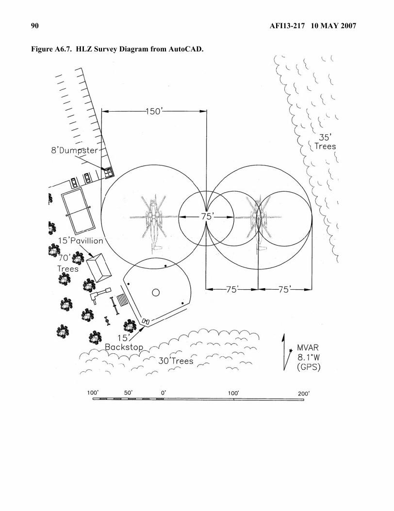
90 AFI13-217 10 MAY 2007
Figure A6.7. HLZ Survey Diagram from AutoCAD.

AFI13-217 10 MAY 2007 91
Attachment 7
GUIDANCE CONCERNING AF FORM 4304, DROP ZONE / LANDING ZONE CONTROL LOG
A7.1. AF Form 4304, Drop Zone / Landing Zone Control Log. IAW paragraph 2.18.4.4., it is theresponsibility of the DZC to ensure this form is complete and accurate. Group Tactics, or equivalent, willmaintain completed AF Form 4304 IAW AFRIMS.
A7.2. Use the instructions listed below to complete AF Form 4304.
A7.2.1. DATE. Enter date and year. Use either calendar or Julian date. When a “time” is required uselocal or GMT consistent with the date.
A7.2.2. LOCATION. Enter DZ name.
A7.2.3. CCT AND UNIT. DZSTL name and unit.
A7.2.4. DZ/LZ CONTROL OFFICER AND UNIT. Self-explanatory.
A7.2.5. DROP ZONE SAFETY OFFICER AND UNIT. Self-explanatory.
A7.2.6. LINE NO. Mission sequence number of each aircraft.
A7.2.7. TYPE ACFT. Mission design series.
A7.2.8. UNIT. Unit of aircraft.
A7.2.9. CALL SIGN. Call sign of lead and, if applicable, formation position number.
A7.2.10. TYPE MSN. Refer to LEGEND for abbreviations.
A7.2.11. ETA. Estimated time of arrival, estimated TOT, or S3 air brief. Keep the unit of time consis-tent throughout the form (e.g., local or GMT).
A7.2.12. ATA/ATD. Actual time of every pass or actual time of departure.
A7.2.13. STRIKE REPORT.
A7.2.13.1. YDS. Distance first jumper/container/pallet lands from PI in yards. If within 25 yardsit is scored a PI.
A7.2.13.2. CLOCK. Use direction of flight as 12 o’clock and back its azimuth as 6 o’clock, esti-mate direction from PI to first jumper/container/pallet. If time and conditions permit, the actualmeasurement is preferred.
A7.2.14. LZ. Mark the “S” box if a landing occurred between the beginning of the touchdown zoneand the first 500 feet. If the landing was not successful (i.e., go-around), short of the touchdown zone,or 500 feet beyond the beginning of the touchdown zone, mark the “U” box and provide comments inthe REMARKS box.
A7.2.15. SURF WIND. Surface wind direction in degrees, and velocity in knots.
A7.2.16. SCORE METHOD. Refer to LEGEND for abbreviations.
A7.2.17. MEAN EFFECTIVE WIND. Time taken and at what altitude.
A7.2.17.1. TIME. Self-explanatory.

92 AFI13-217 10 MAY 2007
A7.2.17.2. ALT. Should be drop altitude.
A7.2.17.3. DIR & LVL. Wind direction in degrees and velocity in knots.
A7.2.18. REMARKS. Enter remarks as appropriate.