Embed Size (px)
Citation preview
PTI Journal Technical Paper
DESIGN OF EXPANSION JOINTS IN PARKING STRUCTURES
By
MOHAMMAD IQBAL
Authorized reprint from: July 2012 issue of the PTI Journal
Copyrighted © 2012, Post-Tensioning Institute All rights reserved.
20 July 2012 | PTI JOURNAL
TECHNICAL PAPER
DesIgn of exPansIon JoInTs In ParkIng sTrucTures
by Mohammad Iqbal
Parking structures are subjected to volume change stresses, which may cause distress in framing elements. Expansion joints are generally introduced in the structures to alleviate the impact of volume change effects. This paper addresses the threshold question of whether an expansion joint is needed in a parking facility and provides performance-based guidelines to assess the need for an expansion joint.
keyworDsCreep; design; expansion joint; parking structures;
prestress; restraint; shrinkage; temperature; volume change.
InTroDucTIonMost parking structures are built using concrete.
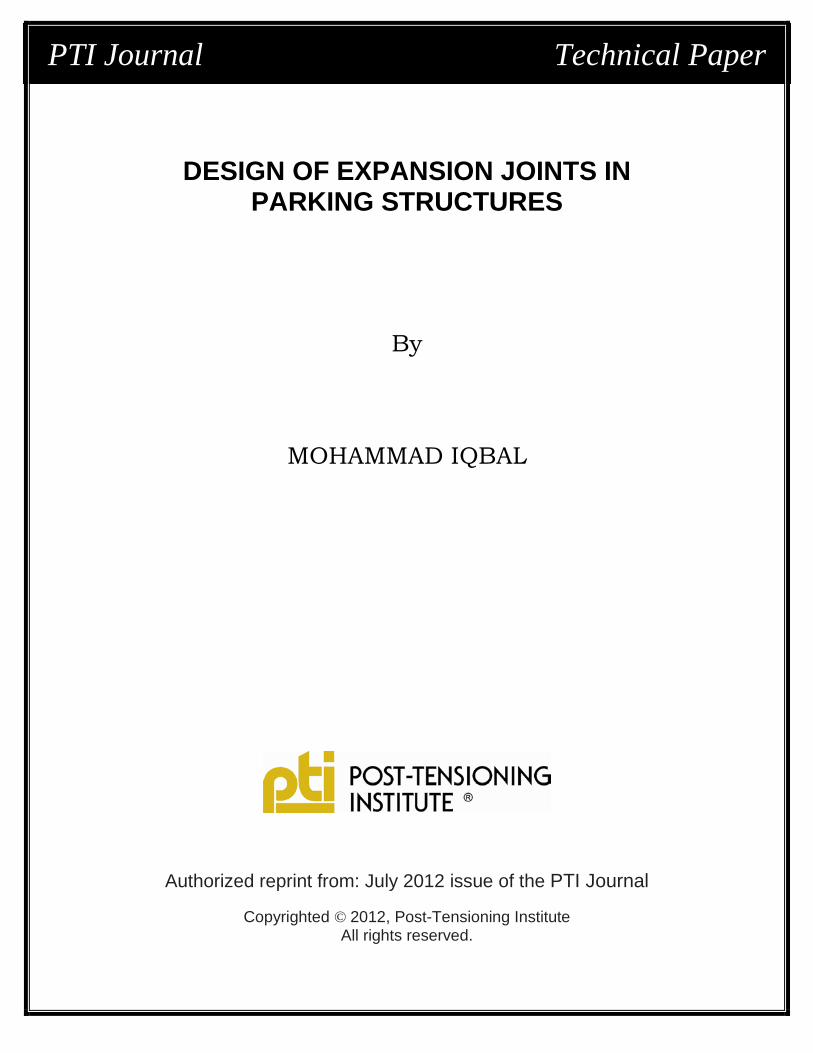
The structures are open and unheated. As such, they are subjected to creep, shrinkage, and temperature (C-S-T) effects. Further, in the case of post-tensioned structures, floor shortening caused by precompression adds to the C-S-T effects in causing structural movement in parking structures. The four factors are jointly known as volume change (VC) effects.1 The restraint to volume changes induces stresses that can cause cracks, leaks, and premature deterioration in concrete structures. To design for the VC effects, ACI 318 requires that design be based on a “realistic assessment” of such effects occurring in service2; however, concrete is a complex nonlinear material. Unlike steel that undergoes neither creep nor shrinkage and has a well-defined coefficient of thermal expansion, concrete offers challenges in realistically assessing its VC effects. The VC deformations accumulate over the building length, as shown in Fig. 1. To limit the stress buildup, expansion joints are introduced by providing an opening or a gap between adjacent structural segments starting from the ground level up to the roof, as shown in Fig. 2. The term “expansion joint” is a misnomer because the joints are introduced primarily to allow shortening, and not expansion, of the structure. The expansion joints are
expensive to install and maintain and, if not maintained, they present a potential hazard to pedestrians who may trip over them and to motorists whose vehicles may bottom out. Therefore, it is desirable to minimize expansion joints in parking structures.
This paper presents the state-of-the-art review of prescriptive requirements to design expansion joints in parking structures, along with recent insight gained in
Fig. 1—Deformed shape of a moment subjected to VC effects.
Fig. 2—Double-column expansion joint in post-tensioned parking structure.
PTI JOURNAL, V. 8, No. 1, July 2012. Received and reviewed under Institute journal publication policies. Copyright ©2012, Post-Tensioning Institute. All rights reserved, including the making of copies unless permission is obtained from the Post-Tensioning Institute. Pertinent discussion will be published in the next issue of PTI JOURNAL if received within 3 months of the publication.
PTI JOURNAL | July 2012 21
TECHNICAL PAPERS
understanding the performance of parking structures under VC effects. Next, major factors influencing the need for expansion joints are discussed. Design guidelines are presented at the end.*
*The design guidelines to size the gap at an expansion join (Fig. 1) were published in Reference 3 and are not repeated in this paper.
HIsTorIcaL BackgrounDA threshold issue in expansion joint design is to
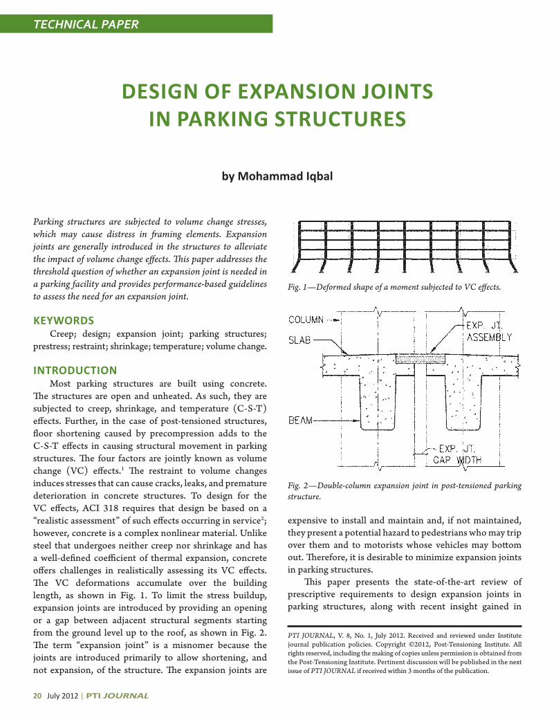
determine the locations or spacing intervals at which the joints should be installed. This issue was addressed 35-plus years ago by the Federal Construction Council (FCC), which developed the first guidelines based on measurements recorded in 1943 in nine buildings.4 For rectangular buildings, the FCC required the expansion joint spacing criteria to consider two factors: design temperature and column base fixity, as shown in Fig. 3. Recognizing the difference in behavior of precast and post-tensioned concrete structural systems, Chrest et al.5 proposed that expansion joints in post-tensioned parking structures should be spaced at 200 ft (61 m) maximum; however, if the floor diaphragm had a pourstrip, the spacing could be increased to 275 ft (84 m).5 Subsequently, the Post-Tensioning Institute (PTI) published its expansion joint guidelines. The PTI guidelines6 are identical to the Chrest et al.5 guidelines, except that PTI increased the expansion joint spacing limits by 50 ft (15 m) in each case, with a caveat that the recommended limits were meant for locations where temperature changes were “not significant” and that they should be modified for locations with “significant” temperature changes. PTI did not define what constitutes a “significant” temperature change; however, it emphasized that the guidelines were based on ideal structural framing layout so that stiff elements such as shear walls are located at or near the center of rigidity of the structure where little movement was expected. Figure 4 illustrates an ideal layout where the center of mass and center of rigidity of the facility coincide. The Chrest et al.5 and PTI6 recommendations were complementary to each other because Chrest et al.5 based their recommendation on parking structures located in the Midwest where temperature differentials are significant and durability is a primary concern, whereas PTI aimed its recommendation for the southwestern part of the U.S. with mild or “nonsignificant” temperatures. Assuming a design temperature (temperature change) of 40°F (22°C) is the line between the significant and nonsignificant temperatures, the PTI6 and Chrest et al.5 recommendations are shown in Fig. 3. Separately, the Precast/Prestressed Concrete Institute (PCI) recommended considering connection deformability, frame stiffness, location of lateral force resisting system (LFRS), and weather exposure conditions in assessing the need for an expansion joint.7 However, PCI did not
Fig. 3—Expansion joint spacing guidelines per References 4 through 6 (Note: 1 ft = 0.31 m and 1°F of design temperature [temperature change] = 0.55°C.)
Fig. 4—LFRS layout to maximize expansion joint spacing (adapted from Reference 5).

22 July 2012 | PTI JOURNAL
TECHNICAL PAPERS TECHNICAL PAPERS
provide any design criteria for the factors affecting the need for an expansion joint in a parking structure.
The purpose of providing an expansion joint is to reduce the VC stress build-up to a tolerable level, and not to eliminate the build-up altogether.2 The ACI 318 commentary states that, where LFRS provides “significant restraint” to shrinkage and temperature movements, it may be necessary to increase the amount of slab reinforcement required to control cracking. ACI 318 does not define what “significant restraint” is. Therefore, the expansion joint spacing criterion remains an unsettled issue; however, establishing a rational expansion joint spacing criterion is important because omitting an expansion joint where it is needed creates a risk of structural distress, causing unnecessary repair costs. On the other hand, installing an expansion joint where it is not needed increases initial construction cost and adds to the maintenance costs of the facility. This paper presents guidelines to optimize the expansion joint spacing and thus enhance structural performance. The guidelines are based on this author’s experience in design of parking structures and in resolving matters related to expansion joints.
DesIgn facTorsThe need to install an expansion joint depends on
several factors including design temperature, structural system type, stiffness, integrity, and framing layout. It is well known that the volume changes increase with the distance from the center of rigidity and reach their maximum at the perimeter (Fig. 1). Because shortening has more pronounced impact on cracking than its expansion counterpart, more emphasis is given to the shortening aspect; however, shortening in a constructed facility does take place in a free or unrestrained manner but is, to a varying degree, restrained by LFRS. An understanding of factors causing shortening on one hand, and restraints to shortening on the other, is essential to assess the need for the expansion joint spacing. The significant factors are discussed as follows.
Design temperatureIt has been recognized that seasonal temperature
changes from anticipated high temperature (Tmax) to low temperature (Tmin) in a locality are the principal cause of shortening. Generally, it takes at least a year to construct a parking structure and, therefore, various structural elements are installed at different temperatures. To simplify determination of design temperature for a structure, the
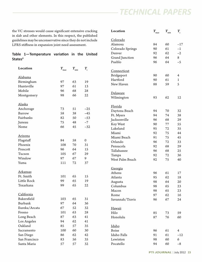
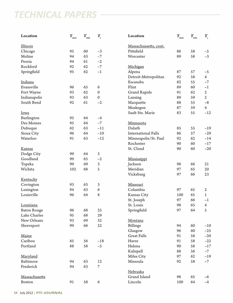
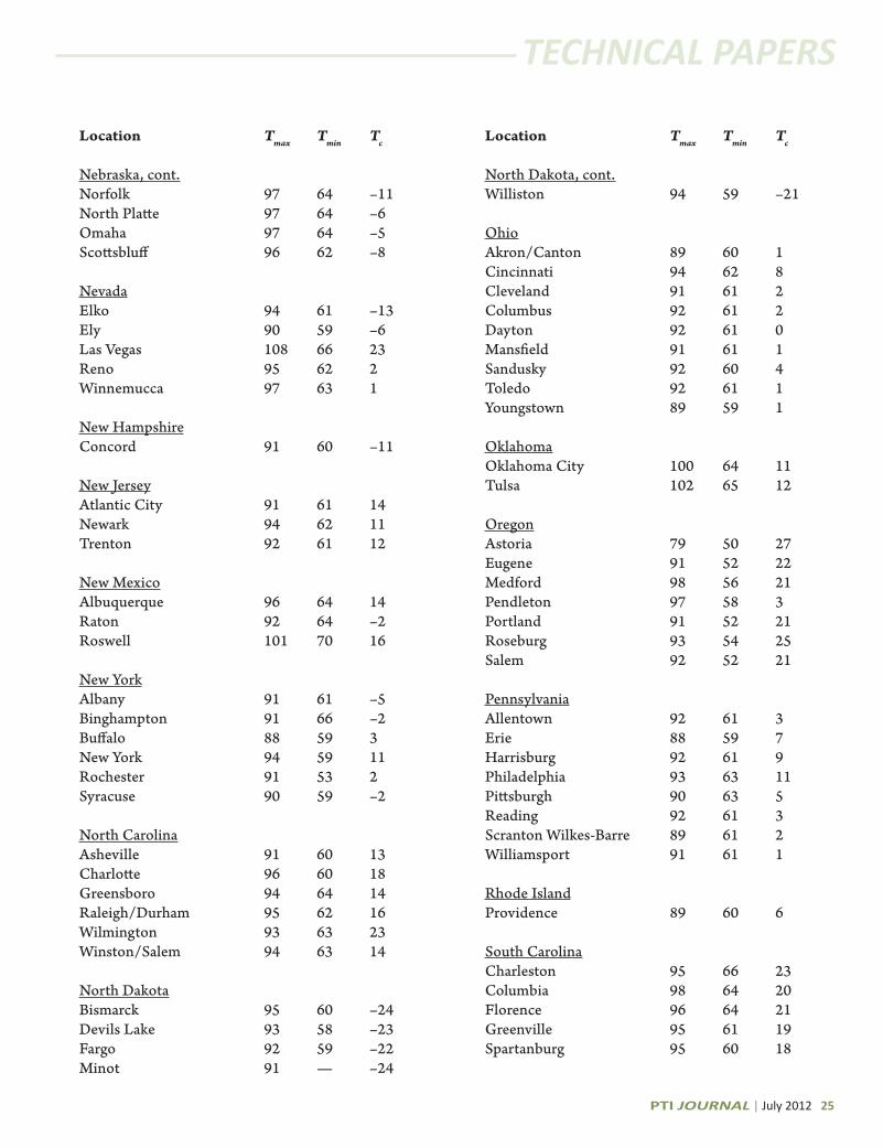
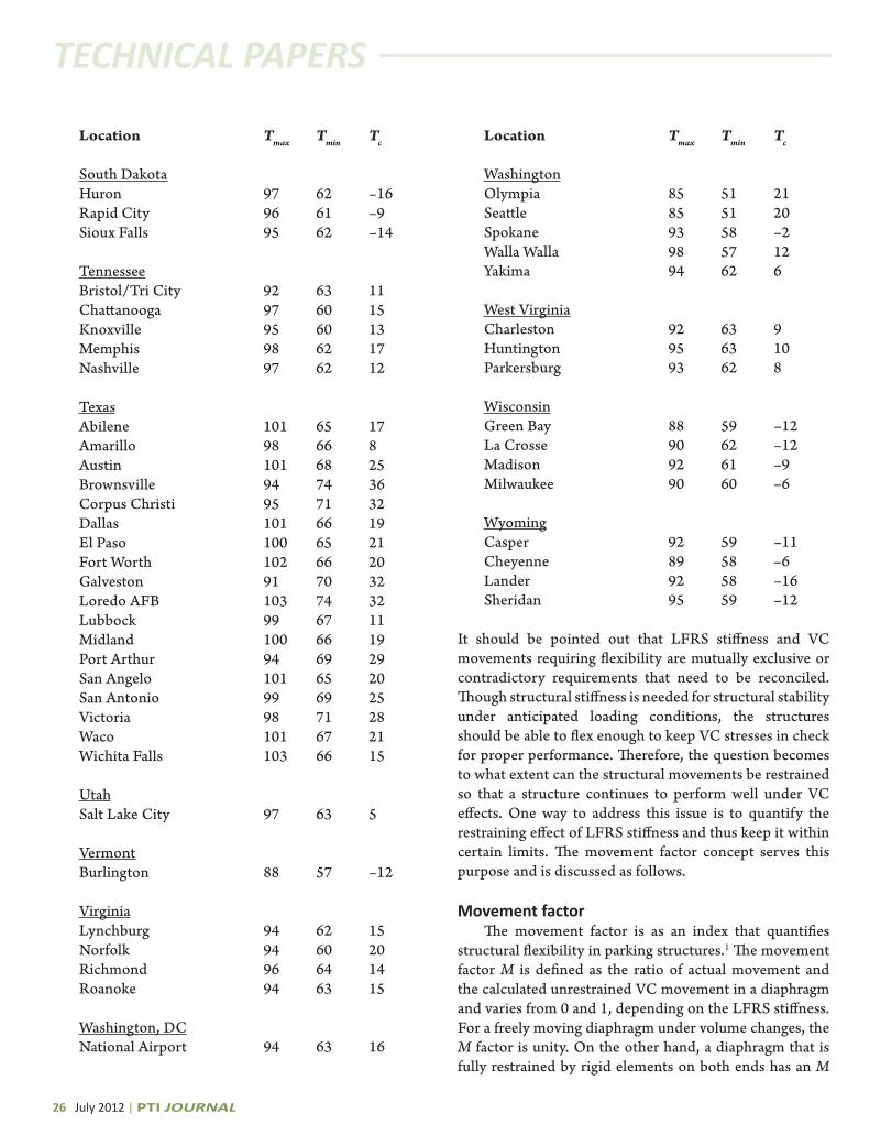
mean construction season temperature (Tc) is generally used.3 As construction is carried out generally in above-freezing temperatures, the temperature Tc is invariably above 32°F (0°C). What temperature values should be used for Tmax, Tmin, and Tc for a location is an important design step. The FCC4 defined Tmax as the temperature exceeded, on average, only 1% of the time during the summer months. Similarly, Tmin is defined as the temperature that equals or exceeds, on average, 99% of the time during the winter months in the locality of the building. The list of temperature variations for cities across the U.S. is given in Table 1. Because thermal shortening is additive to creep and shrinkage effects and manifests in structural distress, the design temperature DT is defined as
DT = T
c – T
min (1)
As shown in Table 1, the design temperature DT varies from 16°F (9°C) for Honolulu, HI, to 103°F (57°C) for Fairbanks, AK, with cities in the 48 contiguous states falling between the two.
structural systemThree types of structural systems used in parking
structures are post-tensioned, pretopped double-T, and field-topped double-T precast concrete systems. The structural system type selected has considerable impact on thermal movements. The post-tensioned structures exhibit more thermal movement than their precast counterpart.1
To alleviate the stress build-up in the post-tensioned diaphragms and to minimize associated cracking, control strips are introduced during construction. The control strips, also called closure strips, delay strips, or pour-strips, help increase flexibility and thus permit initial creep and shrinkage to dissipate. Once the pour strip concrete attains its design strength, the pour strip loses its effectiveness and both sides of the diaphragm act as one unit during the service life of the structure.
Structural stiffnessIt is well known that structures do not move freely
under VC effects, as their movement is inhibited by structural stiffness. An increase in the LFRS stiffness increases restraint and axial tension in the diaphragm. As a result, slab and beams located near the LFRS’s center of rigidity are subjected to the maximum axial stress while its exterior columns are subjected to the maximum bending moment and shear forces.1 If the LFRS is too stiff to flex,
PTI JOURNAL | July 2012 23
TECHNICAL PAPERS TECHNICAL PAPERS
the VC stresses would cause significant extensive cracking in slab and other elements. In this respect, the published guidelines may be unconservative since they do not include LFRS stiffness in expansion joint need assessment.
Table 1—Temperature variation in the United states4
Location Tmax Tmin Tc
AlabamaBirmingham 97 63 19Huntsville 97 61 13Mobile 96 68 28Montgomery 98 66 22
AlaskaAnchorage 73 51 –25Barrow 58 38 –45Fairbanks 82 50 –53Juneau 75 48 –7Nome 66 45 –32
ArizonaFlagstaff 84 58 0Phoenix 108 70 31Prescott 96 64 15Tucson 105 67 29Winslow 97 67 9Yuma 111 72 37
ArkansasFt. Smith 101 65 15Little Rock 99 65 19Texarkana 99 65 22
CaliforniaBakersfield 103 65 31Burbank 97 64 36Eureka/Arcata 67 52 32Fresno 101 63 28Long Beach 87 63 41Los Angeles 94 62 41Oakland 85 57 35Sacramento 100 60 30San Diego 86 62 42San Francisco 83 56 35Santa Maria 57 57 32
Location Tmax Tmin Tc
ColoradoAlamosa 84 60 –17Colorado Springs 90 61 –1Denver 92 62 –2Grand Junction 96 64 8Pueblo 96 64 –5
ConnecticutBridgeport 90 60 4Hartford 90 61 1New Haven 88 59 5
DelawareWilmington 93 62 12
FloridaDaytona Beach 94 70 32Ft. Myers 94 74 38Jacksonville 96 68 29Key West 90 77 55Lakeland 95 72 35Miami 92 75 44Miami Beach 91 75 45Orlando 96 72 33Pensacola 92 68 29Tallahassee 96 68 25Tampa 92 72 36West Palm Beach 92 75 40
GeorgiaAthens 96 61 17Atlanta 95 62 18Augusta 98 64 20Columbus 98 65 23Macon 98 65 23Rome 97 62 16Savannah/Travis 96 67 24 HawaiiHilo 85 73 59Honolulu 87 76 60
IdahoBoise 96 61 4Idaho Falls 91 61 –12Lewiston 98 60 6Pocatello 94 60 –8
24 July 2012 | PTI JOURNAL
TECHNICAL PAPERS TECHNICAL PAPERS
Location Tmax Tmin Tc
IllinoisChicago 95 60 –3Moline 94 63 –7Peoria 94 61 –2Rockford 92 62 –7Springfield 95 62 –1
IndianaEvansville 96 65 6Fort Wayne 93 62 0Indianapolis 93 63 0South Bend 92 61 –2
IowaBurlington 95 64 –4Des Moines 95 64 –7Dubuque 62 63 –11Sioux City 96 64 –10Waterloo 91 63 –12
KansasDodge City 99 64 3Goodland 99 65 –2Topeka 99 69 3Wichita 102 68 5
KentuckyCovington 93 63 3Lexington 94 63 6Louisville 96 64 8
LouisianaBaton Rouge 96 68 25Lake Charles 95 68 29New Orleans 93 69 32Shreveport 99 66 22
MaineCaribou 85 56 –18Portland 88 58 –5
MarylandBaltimore 94 63 12Frederick 94 63 7
MassachusettsBoston 91 58 6
Location Tmax Tmin Tc
Massachussetts, cont.Pittsfield 86 58 –5Worcester 89 58 –3
MichiganAlpena 87 57 –5Detroit-Metropolitan 92 58 4Escanaba 82 55 –7Flint 89 60 –1Grand Rapids 91 62 2Lansing 89 59 2Marquette 88 55 –8Muskegon 87 59 4Sault Ste. Marie 83 55 –12
MinnesotaDuluth 85 55 –19International Falls 86 57 –29Minneapolis/St. Paul 92 62 –14Rochester 90 60 –17St. Cloud 90 60 –20
MississippiJackson 98 66 21Meridian 97 65 20Vicksburg 97 66 23
MissouriColumbia 97 65 2Kansas City 100 65 1St. Joseph 97 66 –1St. Louis 98 65 4Springfield 97 64 5
MontanaBillings 94 60 –10Glasgow 96 60 –25Great Falls 91 58 –20Havre 91 58 –22Helena 90 58 –17Kalispell 88 56 –7Miles City 97 62 –19Missoula 92 58 –7
NebraskaGrand Island 98 65 –6Lincoln 100 64 –4
PTI JOURNAL | July 2012 25
TECHNICAL PAPERS TECHNICAL PAPERS
Location Tmax Tmin Tc
Nebraska, cont.Norfolk 97 64 –11North Platte 97 64 –6Omaha 97 64 –5Scottsbluff 96 62 –8
NevadaElko 94 61 –13Ely 90 59 –6Las Vegas 108 66 23Reno 95 62 2Winnemucca 97 63 1
New HampshireConcord 91 60 –11
New JerseyAtlantic City 91 61 14Newark 94 62 11Trenton 92 61 12
New MexicoAlbuquerque 96 64 14Raton 92 64 –2Roswell 101 70 16
New YorkAlbany 91 61 –5Binghampton 91 66 –2Buffalo 88 59 3New York 94 59 11Rochester 91 53 2Syracuse 90 59 –2
North CarolinaAsheville 91 60 13Charlotte 96 60 18Greensboro 94 64 14Raleigh/Durham 95 62 16Wilmington 93 63 23Winston/Salem 94 63 14
North DakotaBismarck 95 60 –24Devils Lake 93 58 –23Fargo 92 59 –22Minot 91 — –24
Location Tmax Tmin Tc
North Dakota, cont.Williston 94 59 –21
OhioAkron/Canton 89 60 1Cincinnati 94 62 8Cleveland 91 61 2Columbus 92 61 2Dayton 92 61 0Mansfield 91 61 1Sandusky 92 60 4Toledo 92 61 1Youngstown 89 59 1
OklahomaOklahoma City 100 64 11Tulsa 102 65 12
OregonAstoria 79 50 27Eugene 91 52 22Medford 98 56 21Pendleton 97 58 3Portland 91 52 21Roseburg 93 54 25Salem 92 52 21
Pennsylvania Allentown 92 61 3Erie 88 59 7Harrisburg 92 61 9Philadelphia 93 63 11Pittsburgh 90 63 5Reading 92 61 3Scranton Wilkes-Barre 89 61 2Williamsport 91 61 1
Rhode IslandProvidence 89 60 6
South CarolinaCharleston 95 66 23Columbia 98 64 20Florence 96 64 21Greenville 95 61 19Spartanburg 95 60 18
26 July 2012 | PTI JOURNAL
TECHNICAL PAPERS TECHNICAL PAPERS
Location Tmax Tmin Tc
South DakotaHuron 97 62 –16Rapid City 96 61 –9Sioux Falls 95 62 –14
TennesseeBristol/Tri City 92 63 11Chattanooga 97 60 15Knoxville 95 60 13Memphis 98 62 17Nashville 97 62 12
TexasAbilene 101 65 17Amarillo 98 66 8Austin 101 68 25Brownsville 94 74 36Corpus Christi 95 71 32Dallas 101 66 19El Paso 100 65 21Fort Worth 102 66 20Galveston 91 70 32Loredo AFB 103 74 32Lubbock 99 67 11Midland 100 66 19Port Arthur 94 69 29San Angelo 101 65 20San Antonio 99 69 25Victoria 98 71 28Waco 101 67 21Wichita Falls 103 66 15
UtahSalt Lake City 97 63 5
VermontBurlington 88 57 –12
VirginiaLynchburg 94 62 15Norfolk 94 60 20Richmond 96 64 14Roanoke 94 63 15
Washington, DCNational Airport 94 63 16
Location Tmax Tmin Tc
WashingtonOlympia 85 51 21Seattle 85 51 20Spokane 93 58 –2Walla Walla 98 57 12Yakima 94 62 6
West VirginiaCharleston 92 63 9Huntington 95 63 10Parkersburg 93 62 8
WisconsinGreen Bay 88 59 –12La Crosse 90 62 –12Madison 92 61 –9Milwaukee 90 60 –6
WyomingCasper 92 59 –11Cheyenne 89 58 –6Lander 92 58 –16Sheridan 95 59 –12
It should be pointed out that LFRS stiffness and VC movements requiring flexibility are mutually exclusive or contradictory requirements that need to be reconciled. Though structural stiffness is needed for structural stability under anticipated loading conditions, the structures should be able to flex enough to keep VC stresses in check for proper performance. Therefore, the question becomes to what extent can the structural movements be restrained so that a structure continues to perform well under VC effects. One way to address this issue is to quantify the restraining effect of LFRS stiffness and thus keep it within certain limits. The movement factor concept serves this purpose and is discussed as follows.
Movement factorThe movement factor is as an index that quantifies
structural flexibility in parking structures.1 The movement factor M is defined as the ratio of actual movement and the calculated unrestrained VC movement in a diaphragm and varies from 0 and 1, depending on the LFRS stiffness. For a freely moving diaphragm under volume changes, the M factor is unity. On the other hand, a diaphragm that is fully restrained by rigid elements on both ends has an M
PTI JOURNAL | July 2012 27
TECHNICAL PAPERS TECHNICAL PAPERS
factor of zero. The lower bound of the M factor for post-tensioned structures performing satisfactorily in service has been determined to be 0.8.1 The M factor of 0.8 means that a structure moves 80% of the totally unrestrained movement with the remaining 20% movement inhibited by the structural restraint. The 80% movement level also indicates the maximum degree of restraint post-tensioned structures may tolerate while performing reasonably well. For design purposes, the M factor may be defined as a ratio of the first-story VC movement and the corresponding unrestrained VC movement. If an analytical model has an M factor of less than 0.8, it is likely that the underlying structure, when constructed, would not perform well. In such a case, the LFRS should be reexamined and measures should be taken to reduce its stiffness.
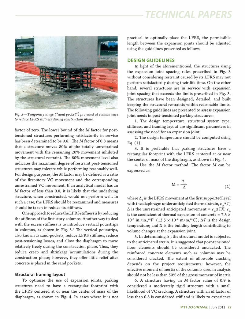
One approach to reduce the LFRS stiffness is by reducing the stiffness of the first story columns. Another way to deal with the excess stiffness is to introduce vertical pourstrips in columns, as shown in Fig. 5.8 The vertical pourstrips, also known as sand-pockets, reduce LFRS stiffness, reduce post-tensioning losses, and allow the diaphragm to move relatively freely during the construction phase. Thus, they reduce creep and shrinkage accumulations during the construction phase; however, they offer little relief after concrete is placed in the sand pockets.
structural framing layoutTo optimize the use of expansion joints, parking
structures need to have a rectangular footprint with the LFRS centered at or near the center of mass of the diaphragm, as shown in Fig. 4. In cases where it is not
practical to optimally place the LFRS, the permissible length between the expansion joints should be adjusted using the guidelines presented as follows.
DesIgn guIDeLInesIn light of the aforementioned, the structures using
the expansion joint spacing rules prescribed in Fig. 3 without considering restraint caused by its LFRS may not perform satisfactorily during their life time. On the other hand, several structures are in service with expansion joint spacing that exceeds the limits prescribed in Fig. 3. The structures have been designed, detailed, and built keeping the structural restraints within reasonable limits. The following guidelines are presented to assess expansion joint needs in post-tensioned parking structures:
1. The design temperature, structural system type, stiffness, and framing layout are significant parameters in assessing the need for an expansion joint.
2. The design temperature should be computed using Eq. (1).
3. It is preferable that parking structures have a rectangular footprint with the LFRS centered at or near the center of mass of the diaphragm, as shown in Fig. 4.
4. Use the M factor method. The factor M can be expressed as:
M = ∆1 ∆
where D1 is the LFRS movement at the first supported level with the diaphragm under anticipated thermal strain, ethDT; D is the unrestrained anticipated movement = ethDTX; eth is the coefficient of thermal expansion of concrete = 7.5 × 10⁻⁶ in./in./°F1 (13.5 × 10⁻⁶ m/m/°C); DT is the design temperature; and X is the building length contributing to volume changes at the expansion joint.
5. In determining D1, the structural model is subjected to the anticipated strain. It is suggested that post-tensioned floor elements should be considered uncracked. The reinforced concrete elements such as columns may be considered cracked. The extent of allowable cracking depends on the project requirements; however, the effective moment of inertia of the columns used in analysis should not be less than 50% of the gross moment of inertia
6. A structure having an M factor value of 0.9 is considered a moderately rigid structure with a small likelihood of VC cracking. A structure with an M factor of less than 0.8 is considered stiff and is likely to experience
(2)
Fig. 5—Temporary hinge (“sand pocket”) provided at column base to reduce LFRS stiffness during construction phase.
TECHNICAL PAPERS
cracking and may require additional reinforcement in various elements to control cracking.
7. For structures with an M factor of less than 0.8, VC stresses can be reduced using sand pockets. However, the number and locations of sand pockets needed to reduce stiffness to a reasonable level depends on the extent of distress and cracking that can be tolerated during the structure’s lifetime.
references1. Iqbal, M., “Thermal Movements in Parking
Structures,” ACI Structural Journal, V. 104, No. 5, Sept.-Oct. 2007, pp. 542-548.
2. ACI Committee 318, “Building Code Requirements for Structural Concrete (ACI 318-05) and Commentary (318R-05),” American Concrete Institute, Farmington Hills, MI, 2005, 430 pp.
3. Iqbal, M., “Seismic Pounding and Expansion Joint Design in Parking Structures,” PTI JOURNAL, V. 7, No. 1, Aug. 2009, pp. 43-51.
4. Federal Construction Council, “Expansion Joints in Buildings,” Technical Report No. 65, Building Research Advisory Board, Division of Engineering, National Academy of Sciences, Washington, DC, 1974, 43 pp.
5. Chrest, A. P.; Smith, M. S.; Bhuyan, B.; Iqbal, M.; and Monahan, D. R., Parking Structures—Planning, Design, Construction, Maintenance and Repairs, third edition, Kluwer Academic Publishers, Boston, MA, 2001, 856 pp.
6. Post-Tensioning Institute, PTI Design, Construction and Maintenance of Cast-In-Place Concrete Parking Structures, sixth edition, Phoenix, AZ, 2006, 354 pp.
7. Prestressed Concrete Institute, PCI Design Handbook, sixth edition, PCI, Chicago, IL, 2004, 720 pp.
8. Iqbal, M., “Advances in Design of Post-Tensioned Parking Facilities in High Seismic Zones,” Ned H. Burns Symposium—Historic Innovation in Prestressed Concrete, SP-231, B. Russell and S. Gross, eds., American Concrete Institute, Farmington Hills, MI, 2005, pp. 198-219.
Mohammad Iqbal is a Consulting Engineer and Lawyer in Elgin, IL. He received his BS in civil engineering from the University of Engineering & Technology (UET), Lahore, Pakistan; his MS from Middle East Technical University (METU), Ankara, Turkey; his DSc from Washington University, St. Louis, MO; and his LLM from the John Marshall Law School, Chicago, IL. He is a licensed PE and SE in several states, has several years of design experience, and is a coauthor of a book on parking structures.
InsistPTI certification of field personnel is an investment that increases efficiency, reduces risk, and provides you with a competitive edge. PTI offers certification programs for personnel involved with field installation, inspection, and supervision; the programs are also beneficial for designers of structures with bonded and unbonded PT and slab-on-ground. Visit www.post-tensioning.org to learn more and register for upcoming workshops or contact PTI to request a special workshop at your facility or job site.
on quality. Insist on safety. Insist on PTI Certified Personnel.