Embed Size (px)
Citation preview

8 audioXpress 03/12 www.audioXpress .com
A look at the bobbin, the voice coil wire, and the collar
The Voice Coil (Part 1)speakers — "parts is parts" By Mike Klasco and Steve Tatarunis (United States)
Photo 1: The construction of a voice coil (Source: Precision Econowind)
Photo 2: High-performance, flat wire coils from Precision Econowind (Source: Precision Econowind)
Photo 3: A voice coil goes through the winding process (Source: Po Yun Enterprise)
In this month’s installment, we’re going to discuss the voice coil. The voice coil comprises three major components: the bob-
bin (also called the former), the voice coil wire, and the collar. The bobbin provides a rigid structure on which the voice coil wire can be wound and the collar can serve several purposes. It se-cures the coil lead-out wires, reinforces the bobbin, and provides a convenient material for diaphragm attachment (see Photo 1).
In some cases—headphone speakers, for example—a monolithic (self support-ing no bobbin or collar) voice coil may be used. But this article will focus on the more commonly used bobbin, coil, and collar designs.
Loudspeaker voice coils are seldom considered critical elements that con-tribute to sound quality, and few techni-cal papers have addressed this issue. But when designing a voice coil, the selection and application of materials can have profound effects upon sound quantity, quality, and power handling. The me-chanical energy from the winding stack moves by transconduction through the bobbin and collar before reaching the diaphragm. Any non-linearities in this path are superimposed upon the response of the speaker. Intrinsic characteristics of materials such as internal damping and Young’s modulus create specific sonic signatures and contribute to the residual distortion spectrum of the transducer (see Photo 2).
In selecting a particular material, a coil winder makes important trade-offs on the winding process. Knowledge of these variables can ensure better, more cost-ef-fective coils, avoid conflicts, and improve production yields. Torsional resonances, internal losses, and electrical conductivity of the bobbin materials are some of the factors effecting the distortion, sensitivity, and sound quality of the finished loud-
speaker. If the bobbin’s wall strength is inadequate, the materials may flex, creat-ing non-linearities, or they may crease or collapse. Virtually all coil components will soften significantly when heated, creating errors, and if the temperature exceeds their limits, they degrade to the next level of distress, which may be out-gassing, blistering, embrittlement, defor-mation, or burning.
Production techniquesMost bobbin and collar materials are
coated with a thin layer of adhesive on one side, and then dried at low tempera-ture without curing the adhesive. These materials are cut to the required dimen-sions from master rolls or large sheets of material. Although some manufacturers cut materials in-house, the majority of them receive it cut into “blanks” by a converter. These voice coil blanks are wrapped around tubular steel or alumi-num winding-mandrels, at which point their name changes from blank to bob-bin. The former is wetted with solvent by brush, by spray, or by in-line wetting of the insulated, adhesive-coated wire. After the wire is wound onto the bobbin, the solvent then activates the adhesives, creating a secure bond between all the components (see Photos 3 and 4).
BoBBin strengthDuring sound reproduction, the cone
resists movement by the actions of iner-tia, the air mass load on the cone surface, and tightness of the back chamber, in-cluding mechanical losses of the suspen-sion elements. If these restrictive forces acting on the cone exceed the mechanical strength of the former, or of the adhesive bonds, then the speaker will fail. Recent subwoofer designs, employing very stiff suspensions, have created unprecedented stress on the former.
To prevent bobbin crushing, design engineers specify appropriate bobbin and
Parts and Production


10 audioXpress 03/12 www.audioXpress .com
Photo 4: A worker inspects the voice coils (Source: Po Yun Enterprise)
Photo 6: A Kapton bobbin voice coil (Source: Precision Econowind)
effective heat path in thermally conductive materials is through the thin film rather than along it, allowing it to transfer heat to the steel pole piece more efficiently, reducing the coil temperature without en-dangering the cone-coil-spider bond or plastic cone materials. Thermal conductiv-ity also spreads the heat from hot regions over a larger area. Various black materials such as black anodized aluminum, black Kapton (MTB and variants), and black composites exploit the “black body effect,” shedding heat more efficiently than pale colored materials. The effectiveness of this emissive cooling is relatively small at ap-proximately 5% (see Photo 5).
The Adhesive BondsThe adhesive coating on the wire and
the adhesive coating on the bobbin must be solvent compatible. Compatibility be-tween former material and coating adhe-sive is more commonly an issue. The low surface energy of polyimide films such as Apical and Kapton, together with their smooth, pore-free surfaces makes them a challenge for any adhesive. Although a driver manufacturer may specify a specific former material, the adhesive coating rarely receives the attention it deserves. Yet, it has dramatic effects on power handling and reliability. At the other end of the scale, Kraft, press, and bond papers have highly porous surfaces, with intrinsically high ad-hesion. But, their propensity to embrittle and adhesive wicking offset this benefit (see Photo 6).
There is also a thermoplastic flow failure, a classic catastrophic failure mode, pro-ducing rapid destruction of the coil struc-ture, as windings slide around, or become loose like “slinky” toys. This failure mode is often seen in wire-to-wire bonds within the winding. One contributing factor is butyl rubber-modified phenolic adhesives, which are strong at room temperature, but their strength drops in a predictable, almost linear manner with increasing tempera-ture. Their thermoplastic flow points run from 160°C for elementary types, approxi-mately 190°C for better wire and competi-tive types, approximately 220°C for highly cross-linked types.
MAgneT Wire insulATionsThe insulation and adhesive coat-
ings must be removed (stripped) to allow electrical termination of the voice coil to
Photo 5: A black bobbin voice coil (Source: MadeInChina.com)
collar materials in a thickness calculated to provide adequate wall strength that will endure some abuse. When drivers are op-erated at high-power levels, the tempera-ture of the voice coil can be greater than 200°C. Clearly the mechanical stiffness of the former and collar materials must be considered at both room temperature and at elevated temperatures. At elevated tem-peratures, all materials soften to a degree. This is especially noticeable with Kapton (polyimide) which softens significantly at extreme elevated temperatures in the mid-200°C range, resulting in deformation or collapse of the former immediately above the winding. Lower-grade polyimides be-come soft at even lower temperatures.
Mechanical property considerations for formers include: dimensional stabil-ity under varying conditions of tempera-ture and humidity, material mass, (specific gravity/weight), stiffness (torsional and flexural modulus), strength (tensile and compressive strength, plastic deformation limit and ultimate yield limit), fabrication and handling criteria, material fatigue, brittleness, and intrinsic damping charac-teristics.
TherMAl ConsiderATionsThe real temperature limit of a driver
may be determined by the failure or soft-ening of any of the following: bobbin ma-terial, bobbin adhesive, wire insulation, wire adhesive, adhesive to cone, spider, or dome, or the materials of cone, spider, or dome.
Wire insulation, bobbin or collar mate-rials, or adhesives with upper temperature limits of less than 180°C are not suitable for high-power drivers, but they are ap-propriate when the input power to the driver is a known and controlled factor, such as a self-amplified subwoofer. Where high-input power is anticipated and not controlled, materials rated for greater than 200°C are required. Because of their graceful over-temperature behavior, some types of 180°C wire are still used. Al-though voice coil materials and adhesives may tolerate exposures to temperatures well beyond their nominal rating, such exposures tend to have a cumulative effect.
Former thermal conductivity has both positive and negative aspects. On the positive side, it sinks heat from the coil, spreading it over a wider area, cooling the winding, which is always good. The most
audioXpress March 2012 11
the tinsel lead-wires. Stripping of these coatings can be performed with chemi-cal agents, a hot solder pot, boiling caustic salts, or a mechanical abrasive. Another option may be ultrasonically welding the wire through the coating, or connecting to the tinsel wire with an insulation piercing crimp.
Dipping the wire ends into a pot of mol-ten solder, which also simultaneously tins them, can strip polyurethane and polyes-ter-based insulations. Higher temperature wire requires stronger treatments, such as dipping in boiling fused salts, which are available from the Eraser Co., New York (315-454-3237). Corrosive chemicals can also be used to strip high-performance wire insulations.
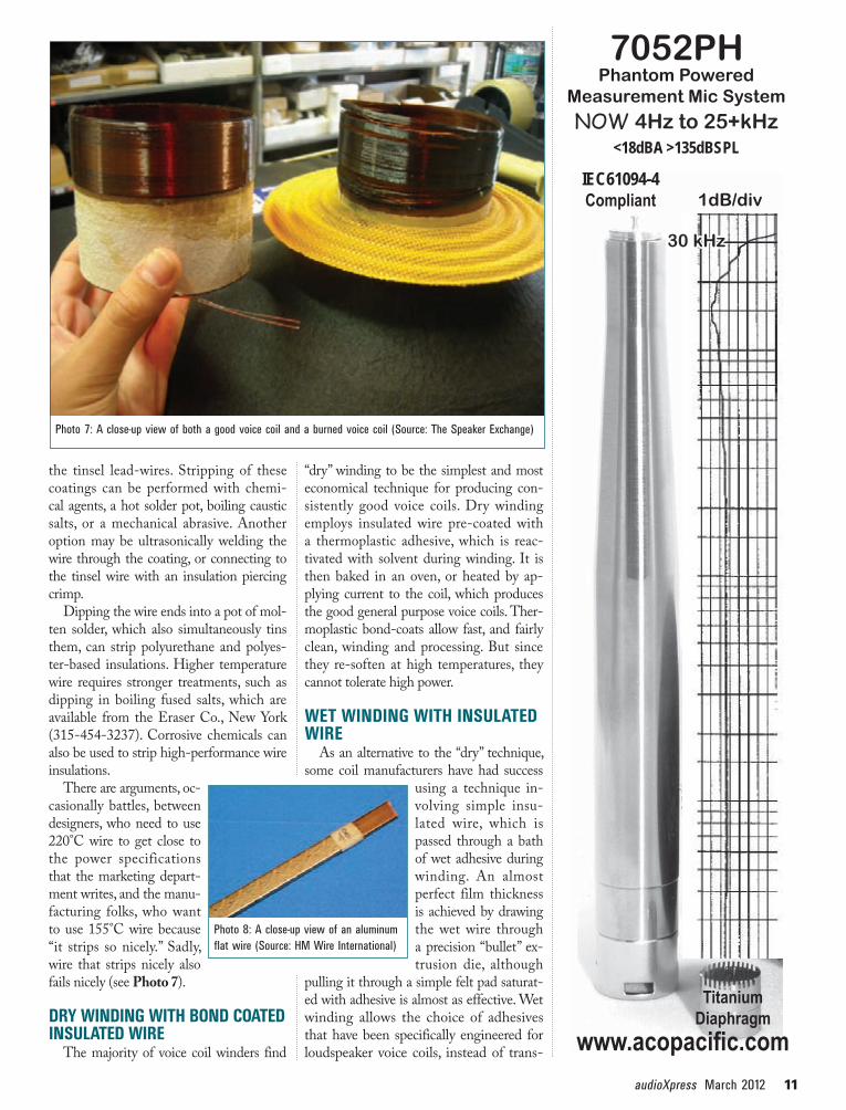
There are arguments, oc-casionally battles, between designers, who need to use 220°C wire to get close to the power specifications that the marketing depart-ment writes, and the manu-facturing folks, who want to use 155°C wire because “it strips so nicely.” Sadly, wire that strips nicely also fails nicely (see Photo 7).
Dry WinDing With BonD CoateD insulateD Wire
The majority of voice coil winders find
Photo 7: A close-up view of both a good voice coil and a burned voice coil (Source: The Speaker Exchange)
“dry” winding to be the simplest and most economical technique for producing con-sistently good voice coils. Dry winding employs insulated wire pre-coated with a thermoplastic adhesive, which is reac-tivated with solvent during winding. It is then baked in an oven, or heated by ap-plying current to the coil, which produces the good general purpose voice coils. Ther-moplastic bond-coats allow fast, and fairly clean, winding and processing. But since they re-soften at high temperatures, they cannot tolerate high power.
Wet WinDing With insulateD Wire
As an alternative to the “dry” technique, some coil manufacturers have had success
using a technique in-volving simple insu-lated wire, which is passed through a bath of wet adhesive during winding. An almost perfect film thickness is achieved by drawing the wet wire through a precision “bullet” ex-trusion die, although
pulling it through a simple felt pad saturat-ed with adhesive is almost as effective. Wet winding allows the choice of adhesives that have been specifically engineered for loudspeaker voice coils, instead of trans-
Photo 8: A close-up view of an aluminum flat wire (Source: HM Wire International)
NOW 4Hz to 25+kHz<18dBA >135dBSPL
7052PHPhantom Powered
Measurement Mic System
www.acopacific.com
1dB/divIEC61094-4Compliant
Titanium Diaphragm
30 kHz

12 audioXpress 03/12 www.audioXpress .com
can be milled into rectangular profiles, although it requires subsequent heat treatment to relieve the work hardening induced by the milling process. For ex-treme power applications, where wire in-sulation enamels may be a limiting factor, aluminum conductors can be anodized with a 0.05-mm layer of anodized insu-lation on all its surfaces (see Photo 8).
Copper-clad aluminum (CCA) wire is a combination of an aluminum conduc-tor, clad with a thin outer layer of copper for easier termination. CCA wire is pro-duced with 10% (USA) and 15% ( Japan) copper by volume, equating to 25 to 37% by weight, making it appreciably heavier than pure aluminum. CCA wire can be milled into flat profiles, or “ribbon” wire, and is then termed CCAR. All of the normal insulation enamels and adhesives are com-patible with aluminum conductors, but few varieties are offered as standard products.
Voice coils continuedNext month, we continue our explora-
tion of voice coils, including secrets of the impact of the materials on sound quality. aX
electric motors and transformers, so it is produced in many gauges. Although cop-per is heavy, it is inexpensive (although it has gone through huge fluctuations during the last decade). Dead-soft an-nealed copper is the reference standard for conductivity, against which all other metals are measured, so it naturally rates 100% on the International Annealed Copper Standard (IACS) scale. High purity, oxygen-free, and long-crystal cop-per can rate up to 102% IACS. Copper wire is available insulated with hundreds of different resins, and some are available with a bondable over-coat. Some insula-tion coats are strong and flexible enough to allow the wire to be flattened (milled) into ribbon profiles. Several manufactur-ers produce voice coil wire in high-aspect ratios, by starting with a bare conduc-tor, which is highly malleable. They mill it to the desired profile, then apply the insulation and bond coats, but this ap-proach requires a substantial investment in equipment.
Aluminum and copper-clad aluminum are options in voice coils where mass is an issue. Like copper, aluminum wire
former and electric motor industry bond coats. Wet wound coils are acknowledged to be superior to “dry” types, and wet winding is practiced extensively in Eu-rope. But since it requires some operator skill, it is not as popular as it should be. Wet winding provides an excellent wire-to-wire bond, and the highest structural strength when used with adhesive-coated formers.
Wire dimensionIn the United States, wire follows the
American Wire Gauge (AWG) scales, which provides convenient increments between sizes, while outside the United States, the metric (IEC) scale dominates. The dimensions of some AWG sizes closely parallel those of IEC wire, and over the range that interests us in the loudspeaker industry, there are near per-fect equivalents.
Wire conductor materialsCopper is the dominant material for
voice coils wire due to its high conduc-tivity and widespread availability. The vast majority of copper wire is used in
Test Equipment Depot800.517.8431
• Oscilloscopes • Power Supplies • Spectrum Analyzers • Digital Multimeters • Network Analyzers • Function Generators • Impedance Analyzers • Frequency Counters • Audio Analyzers • Soldering Equipment • Assembly Hand Tools • Tool Kits • And Many More...
Sales • Repair & Calibration • Rental • Leases
www.TestEquipmentDepot.com