Embed Size (px)
Citation preview
32 J A N U A R Y 2 0 0 8 T R I B O L O G Y & L U B R I C A T I O N T E C H N O L O G Y
By Linda Day
Contributing Editor
32-38 tlt feature 1-08 12/18/07 10:13 AM Page 32
T R I B O L O G Y & L U B R I C A T I O N T E C H N O L O G Y J A N U A R Y 2 0 0 8 3 3
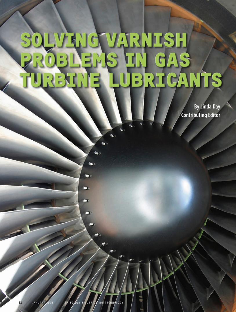
Oxidation and varnish have been recognized as problems since the Civil War,but only in the last few years has the problem reached epidemic propor-tions in power generation and other gas-turbine applications.
“The new turbines that have come on-line in the last five years are designedto put out more energy from smaller equipment,” says Dave Wooton of WootonConsulting, “and that means more stress on the unit and the lubricant.” Butincreasing stress is not the only contributor to the problem. In the same timeframe, turbine users have switched their turbines from base-load to peakingand from Group I base oils to Groups II and III.
“A lot of people blame the new base oils for the problems,” says Wooton,“but I’m not one of them. I do believe the new formulations were puttogether improperly when these oils first came out, because lubricantmanufacturers weren’t accounting for the different chemistry of the base-stocks. But there are many other problems as well.”
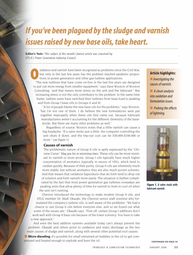
Regardless of source, Wooton notes that a little varnish can cause abig headache: “If a valve sticks just a little, the computer controlling theunit shuts it down, and the trip-out cost can be $30,000-$100,000 ormore.” (see Figure 1)
Causes of varnishThe problematic nature of Group II oils is aptly expressed by the “Chi-nese Curse:” May you live in interesting times. These oils can be more resist-ant to varnish or more prone. Group I oils typically have much higherconcentration of aromatics (typically in excess of 10%), which tend tooxidize quickly. Because of their purity, Group II oils are inherently muchmore stable, but without aromatics they are also much poorer solvents.And that means that oxidation byproducts that do form tend to drop outof solution and form varnish more easily. The situation is further compli-cated by the fact that most power generation gas turbines nowadays are
peaking units that allow plenty of time for varnish to form in cool oil whenthe unit isn’t running.
Chevron introduced the technology to make modern Group II oils, andSTLE member Dr. Mark Okazaki, the Chevron senior staff scientist who for-
mulated the company’s turbine oils, is well aware of the problems: “We had achance to use Group II oils before everyone else, and so we found out what
some of the issues are,” Okazaki says. “First off, certain Group I additives don’twork well with Group II base oils because of the lower solvency. You have to take
a new approach.”And even the best additive systems available today can’t always prevent the
problem. Okazaki and others point to oxidation and static discharge as the twomain causes of sludge and varnish, along with several other potential root causes:
■ Micro-dieseling. It’s possible for small entrained air bubbles in the oil to get com-pressed and heated enough to explode and burn the oil.
If you’ve been plagued by the sludge and varnish
issues raised by new base oils, take heart.
CONTINUED ON PAGE 34
Editor’s Note: This subject of this month’s feature article was conceived bySTLE’s Power Generation Industry Council.
Article highlights:
■ Investigating thecauses of varnish.
■ A closer analysisinto oxidation and formulation issues.
■ Probing the effectsof lightning.
Figure 1. A valve stuck with
lubricant varnish.
32-38 tlt feature 1-08 12/18/07 10:14 AM Page 33
■ Incompatible oils and additives. In somecases, changing to a Group II oil withouttesting the compatibility with the previ-ously used Group I oil can cause decom-posed and/or fresh additives left overfrom Group I to drop out or react in unex-pected ways with the Group II additives.
■ Contamination with chemicals. The pre-servative fluids used to protect new equip-ment from corrosion may not be compati-ble with the turbine oil—turbine oils aretypically ashless (no metals), and the met-als in some preservative and flushing flu-ids (typically calcium) can react with theacidic components of the turbine oils toform an insoluble soap.
■ Contamination with cleaning fluids.This is a special problem in the paperindustry, where machinery may besprayed with lye to clean it.
A closer look at oxidation and formulation“Varnish is the hot issue in gasturbines,” says STLE memberGreg Livingstone, director offluid technology for EPT, Inc.,(Environmental Power Techno-logies) in Calgary, Alberta, Ca-nada, a company that marketsfiltration equipment to removevarnish-forming components.“It’s easy to predict oxidation inGroup I formulations because itproceeds in a predictable, grad-ual and linear fashion, and youhave proven tests to monitor it.But Group II formulations go
along fine with no signs ofbreakdown until suddenly
you’re in total failuremode.” (see Figure 2)
The two main types of antioxidant addi-tives are phenols, good for temperatures upto about 130 C, and amines for tempera-tures above that. If phenols get too hot, theypolymerize and turn into sludge themselves.Amines also have a tendency to polymerizeand turn into varnish when they themselvesoxidize.
The excellent high-temperature perform-ance of amines can sometimes be mislead-ing: Many accelerated tests for oxidation sta-bility are run at high temperatures whereamines perform well, but this may not reflectactual performance in the real world. Phenylalpha naphthyl amine, or PANA, is a goodexample. “A significant amount of PANA givesthe oil an extremely high RPVOT value (ASTMD2272, a measurement of the oil’s resistanceto oxidation),” Livingstone says, “but when itdepletes, it can form tons of varnish andsludge—it actually catalyzes the reaction. TheOEMs don’t restrict the heavy use of thisadditive, and many of the oil companies useit because even though it increases varnishpotential, it gives great oxidation stability(see Figure 3). It’s tough for the end-user tofind out about PANA, because the oil com-panies may not want to reveal their formula-tions.” According to Mark Okazaki, PANA isnot necessarily a problem when used insmall concentrations and in combinationwith other antioxidants such as phenolics.
As it turns out, one of the best ways to
34 J A N U A R Y 2 0 0 8 T R I B O L O G Y & L U B R I C A T I O N T E C H N O L O G Y
CONTINUED FROM PAGE 33
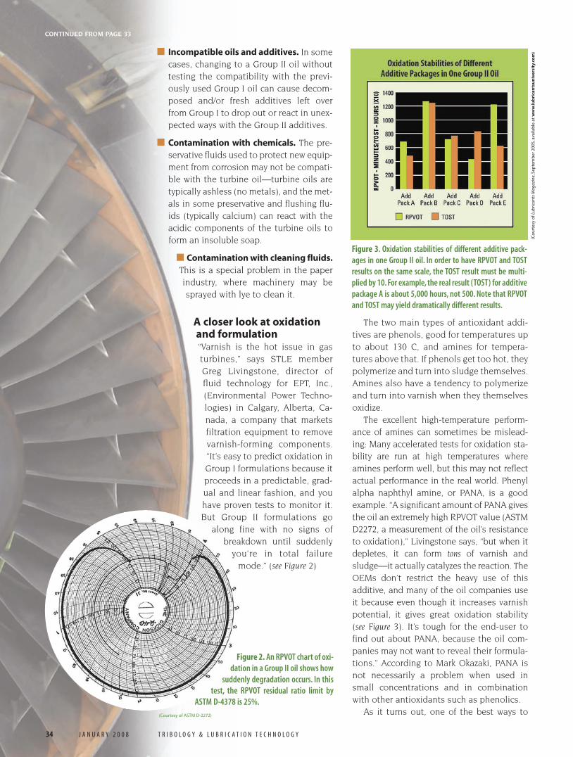
Figure 2. An RPVOT chart of oxi-
dation in a Group II oil shows how
suddenly degradation occurs. In this
test, the RPVOT residual ratio limit by
ASTM D-4378 is 25%.
(Courtesy of ASTM D-2272)
Figure 3. Oxidation stabilities of different additive pack-
ages in one Group II oil. In order to have RPVOT and TOST
results on the same scale, the TOST result must be multi-
plied by 10. For example, the real result (TOST) for additive
package A is about 5,000 hours, not 500. Note that RPVOT
and TOST may yield dramatically different results.
(Co
urt
esy
of L
ubri
cant
s M
agaz
ine,
Sep
tem
ber
200
5,av
aila
ble
at
ww
w.lu
bri
can
tsu
niv
ersi
ty.c
om
)
32-38 tlt feature 1-08 12/18/07 10:14 AM Page 34
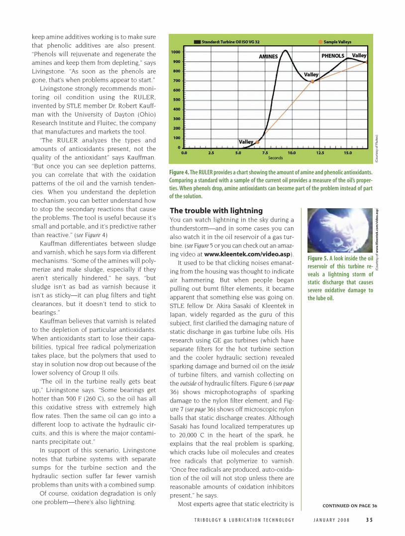
keep amine additives working is to make surethat phenolic additives are also present.“Phenols will rejuvenate and regenerate theamines and keep them from depleting,” saysLivingstone. “As soon as the phenols aregone, that’s when problems appear to start.”
Livingstone strongly recommends moni-toring oil condition using the RULER,invented by STLE member Dr. Robert Kauff-man with the University of Dayton (Ohio)Research Institute and Fluitec, the companythat manufactures and markets the tool.
“The RULER analyzes the types andamounts of antioxidants present, not thequality of the antioxidant” says Kauffman.“But once you can see depletion patterns,you can correlate that with the oxidationpatterns of the oil and the varnish tenden-cies. When you understand the depletionmechanism, you can better understand howto stop the secondary reactions that causethe problems. The tool is useful because it’ssmall and portable, and it’s predictive ratherthan reactive.” (see Figure 4)
Kauffman differentiates between sludgeand varnish, which he says form via differentmechanisms. “Some of the amines will poly-merize and make sludge, especially if theyaren’t sterically hindered,” he says, “butsludge isn’t as bad as varnish because itisn’t as sticky—it can plug filters and tightclearances, but it doesn’t tend to stick tobearings.”
Kauffman believes that varnish is relatedto the depletion of particular antioxidants.When antioxidants start to lose their capa-bilities, typical free radical polymerizationtakes place, but the polymers that used tostay in solution now drop out because of thelower solvency of Group II oils.
“The oil in the turbine really gets beatup,” Livingstone says. “Some bearings gethotter than 500 F (260 C), so the oil has allthis oxidative stress with extremely highflow rates. Then the same oil can go into adifferent loop to activate the hydraulic cir-cuits, and this is where the major contami-nants precipitate out.”
In support of this scenario, Livingstonenotes that turbine systems with separatesumps for the turbine section and thehydraulic section suffer far fewer varnishproblems than units with a combined sump.
Of course, oxidation degradation is onlyone problem—there’s also lightning.
The trouble with lightningYou can watch lightning in the sky during athunderstorm—and in some cases you canalso watch it in the oil reservoir of a gas tur-bine. (see Figure 5 or you can check out an amaz-ing video at www.kleentek.com/video.asp).
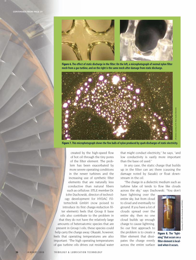
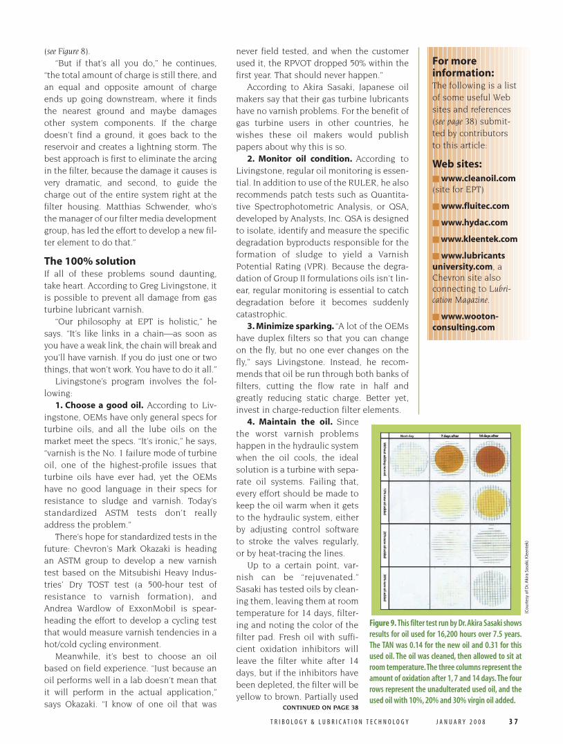
It used to be that clicking noises emanat-ing from the housing was thought to indicateair hammering. But when people beganpulling out burnt filter elements, it becameapparent that something else was going on.STLE fellow Dr. Akira Sasaki of Kleentek inJapan, widely regarded as the guru of thissubject, first clarified the damaging nature ofstatic discharge in gas turbine lube oils. Hisresearch using GE gas turbines (which haveseparate filters for the hot turbine sectionand the cooler hydraulic section) revealedsparking damage and burned oil on the insideof turbine filters, and varnish collecting onthe outside of hydraulic filters. Figure 6 (see page36) shows microphotographs of sparkingdamage to the nylon filter element, and Fig-ure 7 (see page 36) shows off microscopic nylonballs that static discharge creates. AlthoughSasaki has found localized temperatures upto 20,000 C in the heart of the spark, heexplains that the real problem is sparking,which cracks lube oil molecules and createsfree radicals that polymerize to varnish.“Once free radicals are produced, auto-oxida-tion of the oil will not stop unless there arereasonable amounts of oxidation inhibitorspresent,” he says.
Most experts agree that static electricity is
T R I B O L O G Y & L U B R I C A T I O N T E C H N O L O G Y J A N U A R Y 2 0 0 8 3 5
CONTINUED ON PAGE 36
Figure 4. The RULER provides a chart showing the amount of amine and phenolic antioxidants.
Comparing a standard with a sample of the current oil provides a measure of the oil’s proper-
ties. When phenols drop, amine antioxidants can become part of the problem instead of part
of the solution.
(Co
urt
esy
of F
luit
ec)
Figure 5. A look inside the oil
reservoir of this turbine re-
veals a lightning storm of
static discharge that causes
severe oxidative damage to
the lube oil.
(Co
urt
esy
of w
ww
.Kle
ente
k.co
m/v
ideo
.asp
)
32-38 tlt feature 1-08 12/18/07 10:14 AM Page 35
CONTINUED FROM PAGE 35
created by the high-speed flowof hot oil through the tiny poresof the filter element. The prob-lem has been exacerbated bymore severe operating conditionsin the newer turbines and theincreasing use of synthetic filterelements that are naturally lessconductive than natural fibers
such as cellulose. STLE member Dr.John Duchowski, director of technol-
ogy development for HYDAC Fil-tertechnik GmbH (now poised to
introduce its first charge-reduction fil-ter element) feels that Group II base
oils also contribute to the problem inthat they do not have the relatively large
amounts of heteroatomic species that arepresent in Group I oils; these species could
help carry the charge away. Okazaki, however,feels that operating temperatures are alsoimportant: “The high operating temperaturesof gas turbine oils drives out residual water
that might conduct electricity,” he says, “andlow conductivity is vastly more importantthan the base oil used.”
In any case, the static charge that buildsup in the filter can arc there (causing thedamage noted by Sasaki) or float down-stream in the oil.
“The charge in a dielectric medium such asturbine lube oil tends to flow like cloudsacross the sky,” says Duchowski. “You don’thave lightning over theentire sky, but from cloudto cloud and eventually toground. If you have a lot ofclouds spread over theentire sky, then no onecloud builds up enoughcharge to cause lightning.So our first approach tothe problem is to create afilter element that dissi-pates the charge evenlyacross the entire surface
36 J A N U A R Y 2 0 0 8 T R I B O L O G Y & L U B R I C A T I O N T E C H N O L O G Y
Figure 6. The effect of static discharge in the filter: On the left, a microphotograph of normal nylon filter
mesh from a gas turbine, and on the right is the same mesh after damage from static discharge.
Figure 7. This microphotograph shows the fine balls of nylon produced by spark discharges of static electricity.
(All
ph
oto
s co
urt
esy
of D
r.A
kira
Sas
aki,
Kle
ente
k)
(Co
urt
esy
of D
r.Jo
hn
Du
cho
wsk
i an
d H
YD
AC
)
Figure 8. The “light-
ning” that occurs on a
filter element is local-
ized when it occurs.
32-38 tlt feature 1-08 12/18/07 11:09 AM Page 36
T R I B O L O G Y & L U B R I C A T I O N T E C H N O L O G Y J A N U A R Y 2 0 0 8 3 7
(see Figure 8).“But if that’s all you do,” he continues,
“the total amount of charge is still there, andan equal and opposite amount of chargeends up going downstream, where it findsthe nearest ground and maybe damagesother system components. If the chargedoesn’t find a ground, it goes back to thereservoir and creates a lightning storm. Thebest approach is first to eliminate the arcingin the filter, because the damage it causes isvery dramatic, and second, to guide thecharge out of the entire system right at thefilter housing. Matthias Schwender, who’sthe manager of our filter media developmentgroup, has led the effort to develop a new fil-ter element to do that.”
The 100% solutionIf all of these problems sound daunting,take heart. According to Greg Livingstone, itis possible to prevent all damage from gasturbine lubricant varnish.
“Our philosophy at EPT is holistic,” hesays. “It’s like links in a chain—as soon asyou have a weak link, the chain will break andyou’ll have varnish. If you do just one or twothings, that won’t work. You have to do it all.”
Livingstone’s program involves the fol-lowing:
1. Choose a good oil. According to Liv-ingstone, OEMs have only general specs forturbine oils, and all the lube oils on themarket meet the specs. “It’s ironic,” he says,“varnish is the No. 1 failure mode of turbineoil, one of the highest-profile issues thatturbine oils have ever had, yet the OEMshave no good language in their specs forresistance to sludge and varnish. Today’sstandardized ASTM tests don’t reallyaddress the problem.”
There’s hope for standardized tests in thefuture: Chevron’s Mark Okazaki is headingan ASTM group to develop a new varnishtest based on the Mitsubishi Heavy Indus-tries’ Dry TOST test (a 500-hour test ofresistance to varnish formation), andAndrea Wardlow of ExxonMobil is spear-heading the effort to develop a cycling testthat would measure varnish tendencies in ahot/cold cycling environment.
Meanwhile, it’s best to choose an oilbased on field experience. “Just because anoil performs well in a lab doesn’t mean thatit will perform in the actual application,”says Okazaki. “I know of one oil that was
never field tested, and when the customerused it, the RPVOT dropped 50% within thefirst year. That should never happen.”
According to Akira Sasaki, Japanese oilmakers say that their gas turbine lubricantshave no varnish problems. For the benefit ofgas turbine users in other countries, hewishes these oil makers would publishpapers about why this is so.
2. Monitor oil condition. According toLivingstone, regular oil monitoring is essen-tial. In addition to use of the RULER, he alsorecommends patch tests such as Quantita-tive Spectrophotometric Analysis, or QSA,developed by Analysts, Inc. QSA is designedto isolate, identify and measure the specificdegradation byproducts responsible for theformation of sludge to yield a VarnishPotential Rating (VPR). Because the degra-dation of Group II formulations oils isn’t lin-ear, regular monitoring is essential to catchdegradation before it becomes suddenlycatastrophic.
3. Minimize sparking. “A lot of the OEMshave duplex filters so that you can changeon the fly, but no one ever changes on thefly,” says Livingstone. Instead, he recom-mends that oil be run through both banks offilters, cutting the flow rate in half andgreatly reducing static charge. Better yet,invest in charge-reduction filter elements.
4. Maintain the oil. Sincethe worst varnish problemshappen in the hydraulic systemwhen the oil cools, the idealsolution is a turbine with sepa-rate oil systems. Failing that,every effort should be made tokeep the oil warm when it getsto the hydraulic system, eitherby adjusting control softwareto stroke the valves regularly,or by heat-tracing the lines.
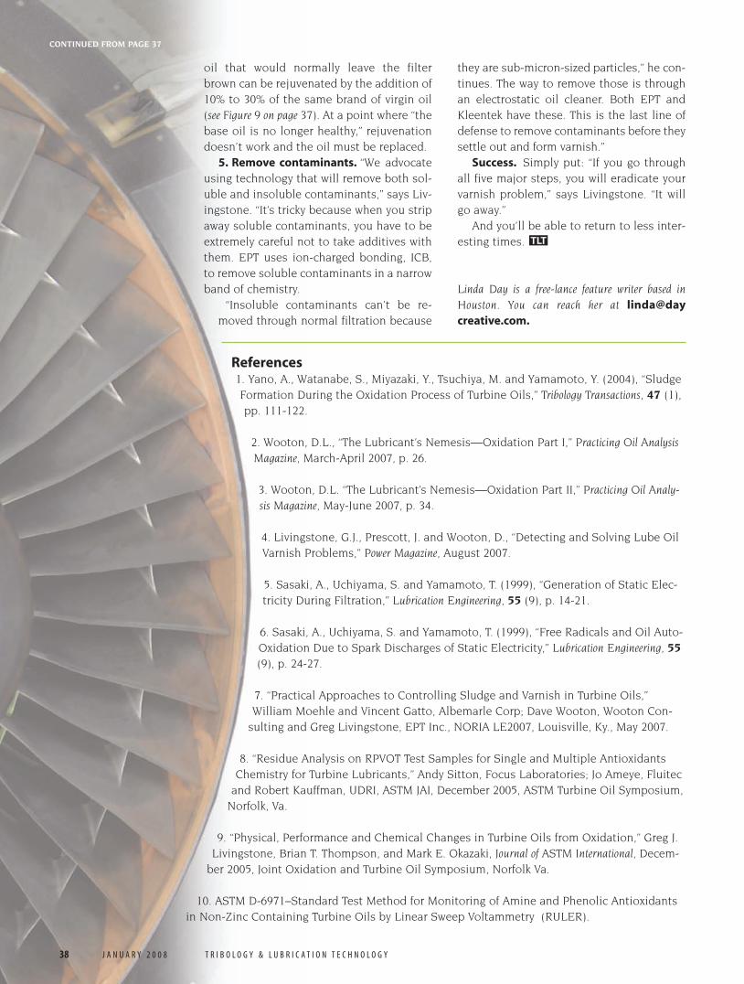
Up to a certain point, var-nish can be “rejuvenated.”Sasaki has tested oils by clean-ing them, leaving them at roomtemperature for 14 days, filter-ing and noting the color of thefilter pad. Fresh oil with suffi-cient oxidation inhibitors willleave the filter white after 14days, but if the inhibitors havebeen depleted, the filter will beyellow to brown. Partially used
For moreinformation:The following is a listof some useful Websites and references(see page 38) submit-ted by contributorsto this article:
Web sites:■ www.cleanoil.com(site for EPT)
■ www.fluitec.com
■ www.hydac.com
■ www.kleentek.com
■ www.lubricantsuniversity.com, aChevron site alsoconnecting to Lubri-cation Magazine.
■ www.wooton-consulting.com
Figure 9. This filter test run by Dr.Akira Sasaki shows
results for oil used for 16,200 hours over 7.5 years.
The TAN was 0.14 for the new oil and 0.31 for this
used oil. The oil was cleaned, then allowed to sit at
room temperature.The three columns represent the
amount of oxidation after 1, 7 and 14 days. The four
rows represent the unadulterated used oil, and the
used oil with 10%, 20% and 30% virgin oil added.
(Co
urt
esy
of D
r.A
kira
Sas
aki,
Kle
ente
k)
CONTINUED ON PAGE 38
32-38 tlt feature 1-08 12/18/07 10:15 AM Page 37
CONTINUED FROM PAGE 37
oil that would normally leave the filterbrown can be rejuvenated by the addition of10% to 30% of the same brand of virgin oil(see Figure 9 on page 37). At a point where “thebase oil is no longer healthy,” rejuvenationdoesn’t work and the oil must be replaced.
5. Remove contaminants. “We advocateusing technology that will remove both sol-uble and insoluble contaminants,” says Liv-ingstone. “It’s tricky because when you stripaway soluble contaminants, you have to beextremely careful not to take additives withthem. EPT uses ion-charged bonding, ICB,to remove soluble contaminants in a narrowband of chemistry.
“Insoluble contaminants can’t be re-moved through normal filtration because
they are sub-micron-sized particles,” he con-tinues. The way to remove those is throughan electrostatic oil cleaner. Both EPT andKleentek have these. This is the last line ofdefense to remove contaminants before theysettle out and form varnish.”
Success. Simply put: “If you go throughall five major steps, you will eradicate yourvarnish problem,” says Livingstone. “It willgo away.”
And you’ll be able to return to less inter-esting times.
Linda Day is a free-lance feature writer based inHouston. You can reach her at [email protected].
TLT
38 J A N U A R Y 2 0 0 8 T R I B O L O G Y & L U B R I C A T I O N T E C H N O L O G Y
References1. Yano, A., Watanabe, S., Miyazaki, Y., Tsuchiya, M. and Yamamoto, Y. (2004), “SludgeFormation During the Oxidation Process of Turbine Oils,” Tribology Transactions, 47 (1),pp. 111-122.
2. Wooton, D.L., “The Lubricant’s Nemesis—Oxidation Part I,” Practicing Oil AnalysisMagazine, March-April 2007, p. 26.
3. Wooton, D.L. “The Lubricant’s Nemesis—Oxidation Part II,” Practicing Oil Analy-sis Magazine, May-June 2007, p. 34.
4. Livingstone, G.J., Prescott, J. and Wooton, D., “Detecting and Solving Lube OilVarnish Problems,” Power Magazine, August 2007.
5. Sasaki, A., Uchiyama, S. and Yamamoto, T. (1999), “Generation of Static Elec-tricity During Filtration,” Lubrication Engineering, 55 (9), p. 14-21.
6. Sasaki, A., Uchiyama, S. and Yamamoto, T. (1999), “Free Radicals and Oil Auto-Oxidation Due to Spark Discharges of Static Electricity,” Lubrication Engineering, 55(9), p. 24-27.
7. “Practical Approaches to Controlling Sludge and Varnish in Turbine Oils,”William Moehle and Vincent Gatto, Albemarle Corp; Dave Wooton, Wooton Con-
sulting and Greg Livingstone, EPT Inc., NORIA LE2007, Louisville, Ky., May 2007.
8. “Residue Analysis on RPVOT Test Samples for Single and Multiple AntioxidantsChemistry for Turbine Lubricants,” Andy Sitton, Focus Laboratories; Jo Ameye, Fluitec
and Robert Kauffman, UDRI, ASTM JAI, December 2005, ASTM Turbine Oil Symposium,Norfolk, Va.
9. “Physical, Performance and Chemical Changes in Turbine Oils from Oxidation,” Greg J.Livingstone, Brian T. Thompson, and Mark E. Okazaki, Journal of ASTM International, Decem-
ber 2005, Joint Oxidation and Turbine Oil Symposium, Norfolk Va.
10. ASTM D-6971–Standard Test Method for Monitoring of Amine and Phenolic Antioxidantsin Non-Zinc Containing Turbine Oils by Linear Sweep Voltammetry (RULER).
32-38 tlt feature 1-08 12/18/07 10:15 AM Page 38