Embed Size (px)
Citation preview
BYEleazar Chidke Okereke
105537
ITEC546 Storage and File Structure 1
Overview of Physical Storage Media Magnetic Disks RAID Tertiary Storage Storage Access File Organization Organization of Records in Files File Organization in Oracle
ITEC546 Storage and File Structure 2
Speed with which data can be accessed Cost per unit of data Reliability
data loss on power failure or system crash physical failure of the storage device
Can differentiate storage into: volatile storage: loses contents when power is
switched off non-volatile storage: contents persist even when
power is switched off. Includes secondary and tertiary storage, as well as battery-backed up main-memory.
ITEC546 Storage and File Structure 3
Cache-fastest and most costly form of storage; volatile; managed by the hardware/operating system.
Main memory: general-purpose machine instructions
operate on data resident in main memory fast access, but generally too small to store
the entire database sometimes referred to as core memory volatile — contents of main memory are
usually lost if a power failure or system crash occurs
ITEC546 Storage and File Structure 4
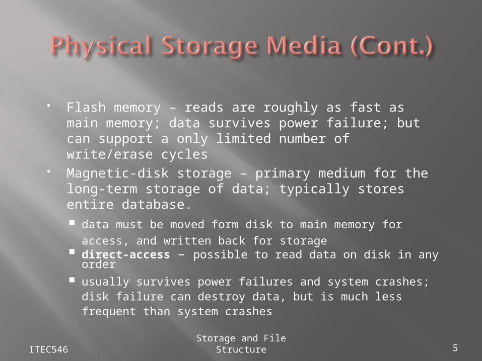
Flash memory – reads are roughly as fast as main memory; data survives power failure; but can support a only limited number of write/erase cycles
Magnetic-disk storage – primary medium for the long-term storage of data; typically stores entire database. data must be moved form disk to main memory for
access, and written back for storage direct-access – possible to read data on disk in any
order usually survives power failures and system crashes; disk
failure can destroy data, but is much less frequent than system crashes
ITEC546 Storage and File Structure 5
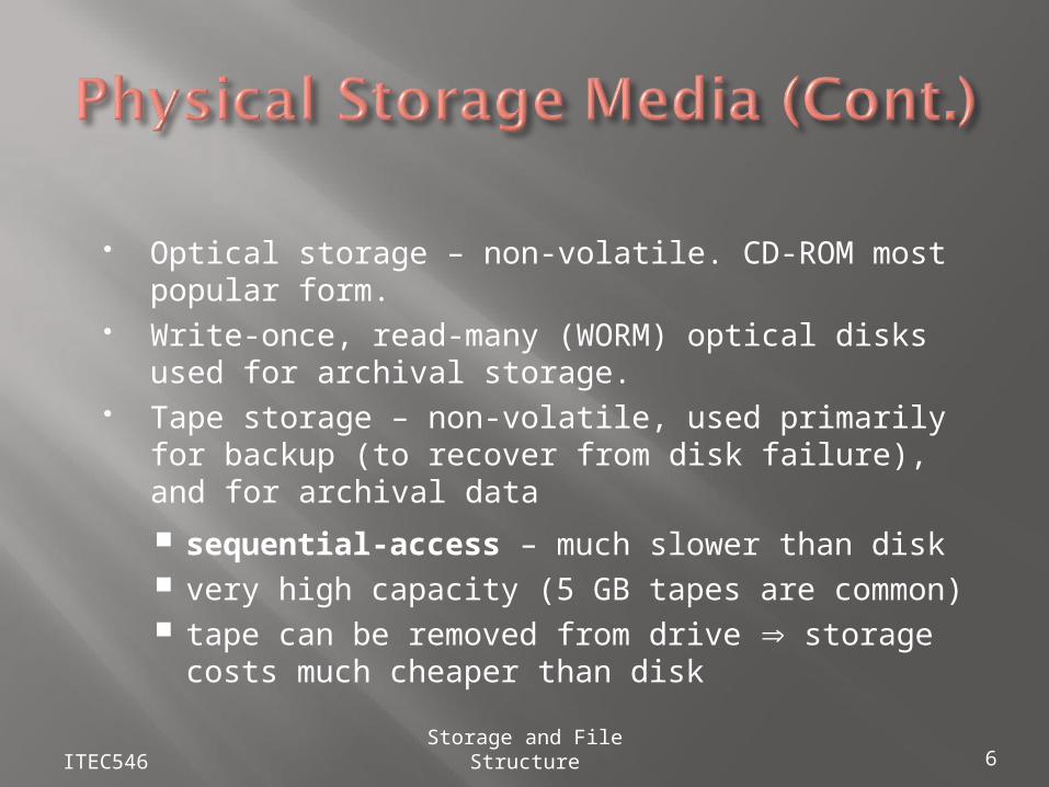
Optical storage – non-volatile. CD-ROM most popular form.
Write-once, read-many (WORM) optical disks used for archival storage.
Tape storage – non-volatile, used primarily for backup (to recover from disk failure), and for archival data
sequential-access – much slower than disk very high capacity (5 GB tapes are common) tape can be removed from drive storage costs
much cheaper than disk
ITEC546 Storage and File Structure 6
ITEC546 Storage and File Structure 7
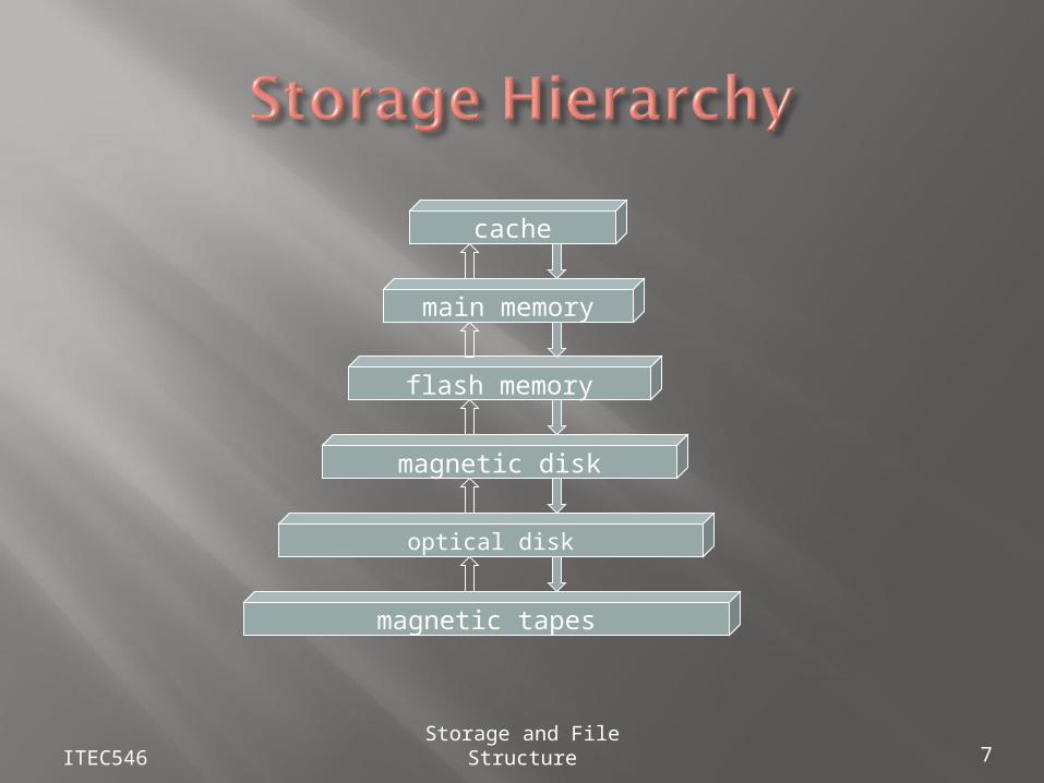
main memory
flash memory
cache
magnetic disk
magnetic tapes
optical disk
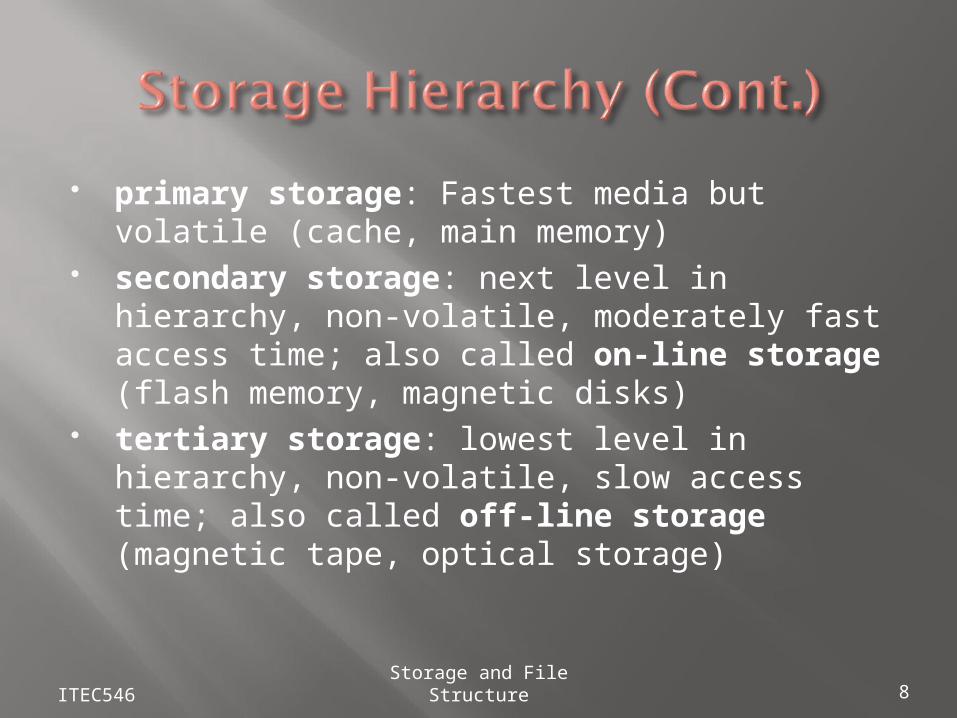
primary storage: Fastest media but volatile (cache, main memory)
secondary storage: next level in hierarchy, non-volatile, moderately fast access time; also called on-line storage (flash memory, magnetic disks)
tertiary storage: lowest level in hierarchy, non-volatile, slow access time; also called off-line storage (magnetic tape, optical storage)
ITEC546 Storage and File Structure 8
ITEC546 Storage and File Structure 9
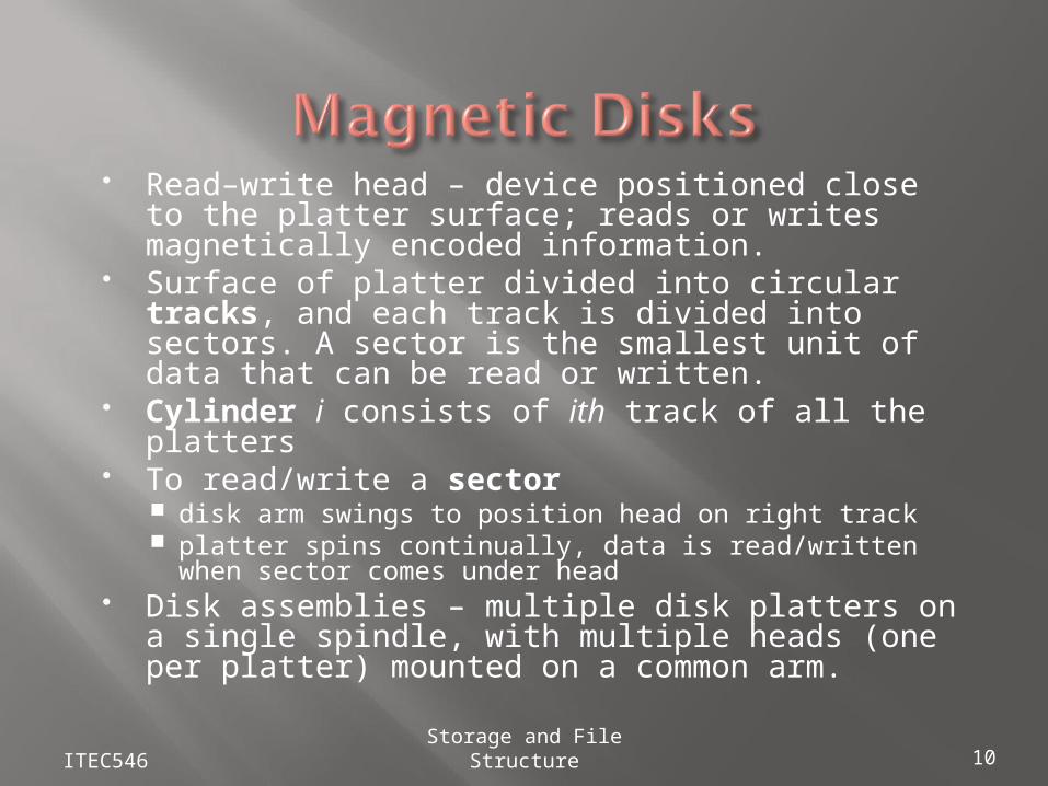
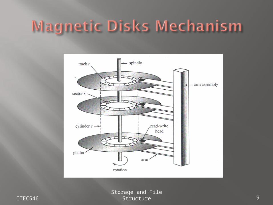
Read–write head – device positioned close to the platter surface; reads or writes magnetically encoded information.
Surface of platter divided into circular tracks, and each track is divided into sectors. A sector is the smallest unit of data that can be read or written.
Cylinder i consists of ith track of all the platters To read/write a sector
disk arm swings to position head on right track platter spins continually, data is read/written when
sector comes under head Disk assemblies – multiple disk platters on a
single spindle, with multiple heads (one per platter) mounted on a common arm.
ITEC546 Storage and File Structure 10
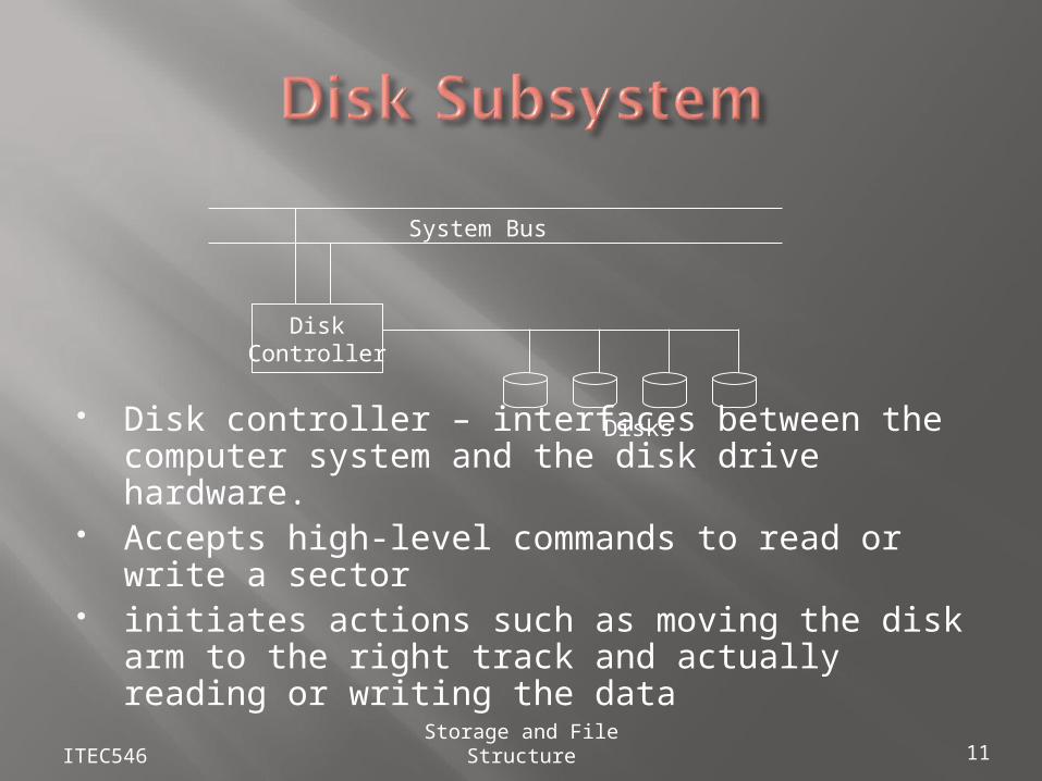
Disk controller – interfaces between the computer system and the disk drive hardware.
Accepts high-level commands to read or write a sector
initiates actions such as moving the disk arm to the right track and actually reading or writing the data
ITEC546 Storage and File Structure 11
DiskController
System Bus
Disks
Access time – the time it takes from when a read or write request is issued to when data transfer begins. Consists of: Seek time – time it takes to reposition the arm over
that correct track. Average seek time is 1/3rd the worst case seek time.
Rotational latency – time it takes for the sector to be accessed to appear under the head. Average latency is 1/2 of the worst case latency.
Data-transfer rate – the rate at which data can be retrieved from or stored to the disk.
Mean time to failure (MTTF) – the average time the disk is expected to run continuously without any failure.
ITEC546 Storage and File Structure 12
Block – a contiguous sequence of sectors form a single track data is transferred between disk and main memory in blocks sizes range from 512 bytes to several kilobytes
Disk-arm–scheduling algorithms order accesses to tracks so that disk arm movement is minimized (elevator algorithm is often used)
File organization – optimize block access time by organizing the blocks to correspond to how data will be accessed. Store related information on the same or nearby cylinders.
Nonvolatile write buffers speed up disk writes by writing blocks to a non-volatile RAM buffer immediately; controller then writes to disk whenever the disk has no other requests.
Log disk – a disk devoted to writing a sequential log of block updates; this eliminates seek time. Used like nonvolatile RAM.
ITEC546 Storage and File Structure 13
Redundant Arrays of Inexpensive Disks – disk organization techniques that take advantage of utilizing large numbers of inexpensive, mass-market disks.
Originally a cost-effective alternative to large, expensive disks.
Today RAIDs are used for their higher reliability and bandwidth, rather than for economic reasons. Hence the “I” is interpreted as independent, instead of inexpensive.
ITEC546 Storage and File Structure 14
The chance that some disk out of a set of N disks will fail is much higher than the chance that a specific single disk will fail.E.g., a system with 100 disks, each with MTTF of 100,000 hours (approx. 11 years), will have a system MTTF of 1000 hours (approx. 41 days)
Redundancy – store extra information that can be used to rebuild information lost in a disk failure
E.g. Mirroring ( or shadowing) duplicate every disk. Logical disk consists of two
physical disks. Every write is carried out on both disks if one disk in a pair fails, data still available in the
other
ITEC546 Storage and File Structure 15
Two main goals of parallelism in a disk system:1. Load balance multiple small accesses to increase throughput2. Parallelize large accesses to reduce response time
Improve transfer rate by striping data across multiple disks
Bit-level striping – split the bits of each byte across multiple disks In an array of eight disks, write bit i of each byte to disk i.
Each access can transfer data eight times faster than a single disk.
But seek/access time worse than for a single disk. Block-level striping – with n disks, block i of a file
goes to disk (i mod n) + 1
ITEC546 Storage and File Structure 16
ITEC546 Storage and File Structure 17
c
p p p
p
p
p
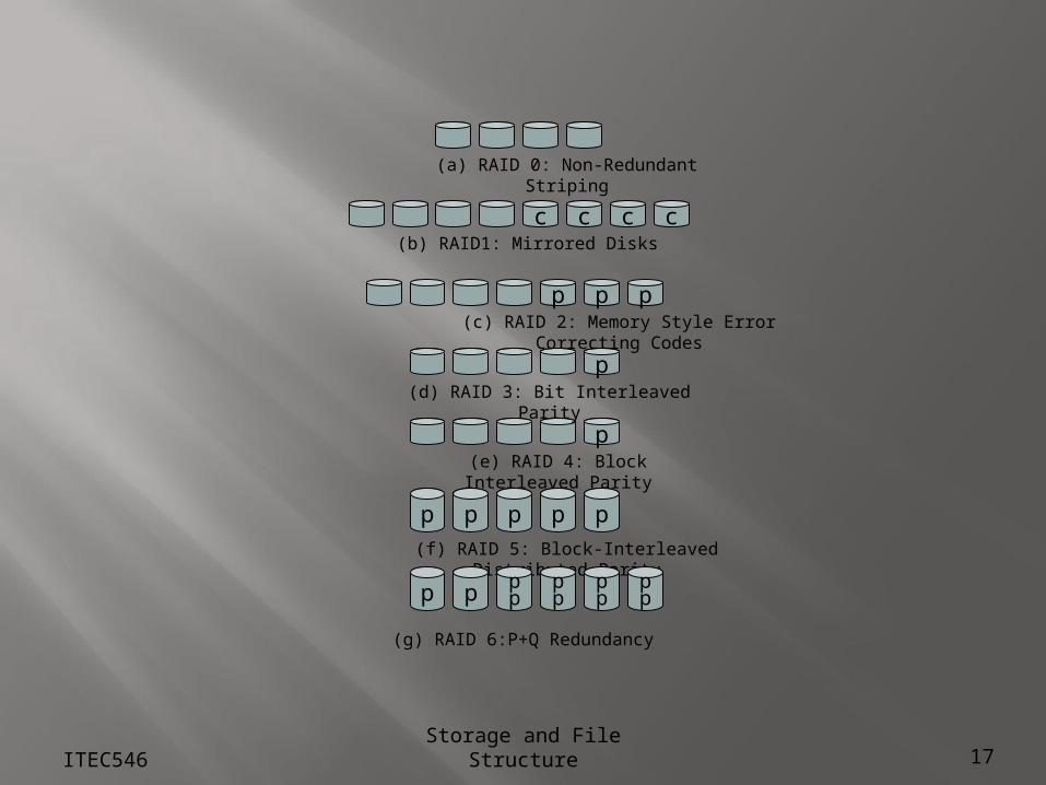
(a) RAID 0: Non-Redundant Striping
(d) RAID 3: Bit Interleaved Parity
(e) RAID 4: Block Interleaved Parity
(f) RAID 5: Block-Interleaved Distributed Parity
(g) RAID 6:P+Q Redundancy
(b) RAID1: Mirrored Disks
(c) RAID 2: Memory Style Error Correcting Codes
ccc
p p p p
p p pp
pp
pp
pp
Schemas to provide redundancy at lower cost by using disk striping combined with parity bits
Different RAID organizations, or RAID levels, have differing cost, performance and reliability characteristics
Level 0: Striping at the level of blocks; non-redundant. Used in applications where data loss is not critical. Best write performance. Cheapest way to improve performance.
Level 1: Mirrored disks. Subsumed by level 0+1. Level 0+1: Mirrored disks with striping; offers best
read performance and good write performance. Popular for applications such as storing log files in a database system.
ITEC546 Storage and File Structure 18
Level 2: Memory-Style Error-Correcting-Codes (ECC) with bit striping.
Level 3: Bit-Interleaved Parity; a single parity bit can be used for error correction, not just detection. When writing data, parity bit must also be computed and
written With D data disks, the minimum block size is D sectors Writing a single block involves writing a complete stripe
including the parity (no read-modify-write cycle required). Faster data transfer than with a single disk, but longer
average seek time since every disk has to participate in every I/O.
Subsumes Level 2 (provides all its benefits, at lower cost).
ITEC546 Storage and File Structure 19
Level 4: Block-Interleaved Parity; uses block-level striping, and keeps a parity block on a separate disk for corresponding blocks from N other disks. Provides faster average seek rates for independent
block reads than Level 3 (block read goes to a single disk)
Provides high transfer rates for reads of multiple blocks since blocks on different disks can be read in parallel.
However, parity block becomes a bottleneck for parallel block writes since every block write also writes to parity disk.
Single block writes require read-modify-write cycle to compute parity: read old data and parity blocks and compare new data to old to determine which parity bits to flip. Four disk i/o’s total.
ITEC546 Storage and File Structure 20
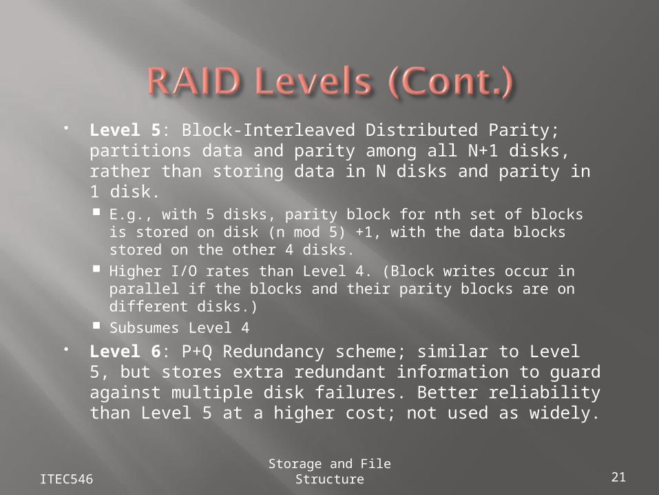
Level 5: Block-Interleaved Distributed Parity; partitions data and parity among all N+1 disks, rather than storing data in N disks and parity in 1 disk. E.g., with 5 disks, parity block for nth set of blocks is stored
on disk (n mod 5) +1, with the data blocks stored on the other 4 disks.
Higher I/O rates than Level 4. (Block writes occur in parallel if the blocks and their parity blocks are on different disks.)
Subsumes Level 4 Level 6: P+Q Redundancy scheme; similar to Level 5,
but stores extra redundant information to guard against multiple disk failures. Better reliability than Level 5 at a higher cost; not used as widely.
ITEC546 Storage and File Structure 21
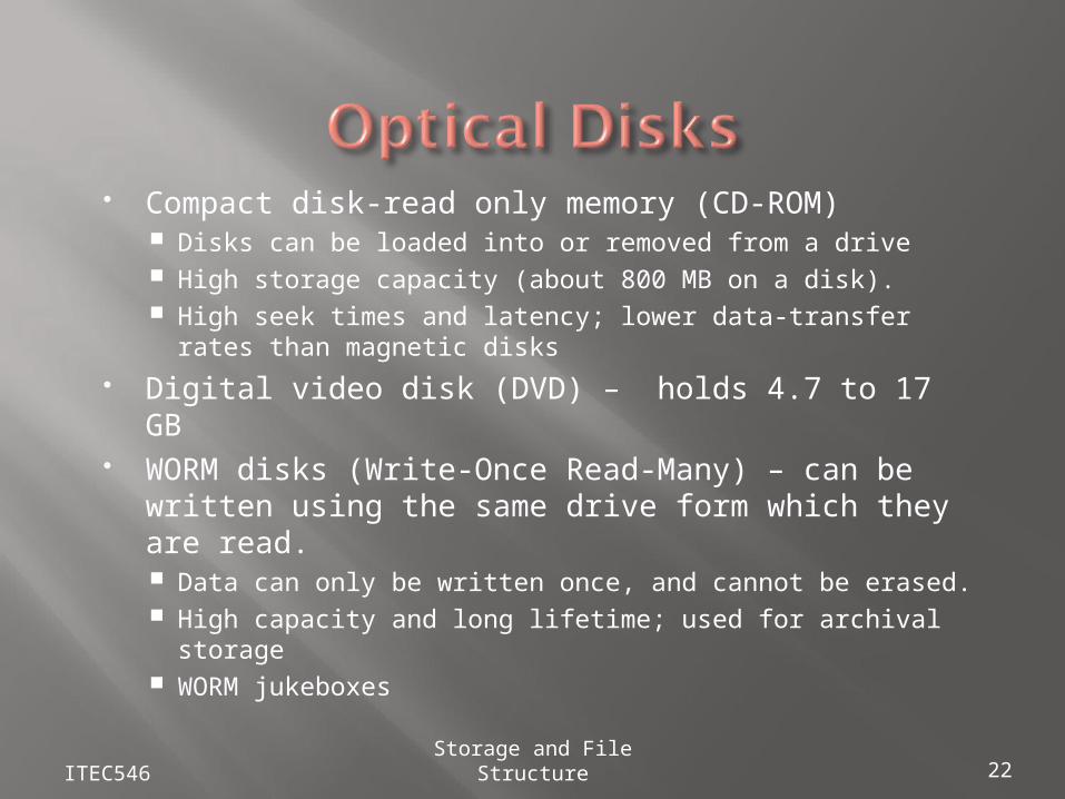
Compact disk-read only memory (CD-ROM) Disks can be loaded into or removed from a drive High storage capacity (about 800 MB on a disk). High seek times and latency; lower data-transfer rates
than magnetic disks Digital video disk (DVD) – holds 4.7 to 17 GB WORM disks (Write-Once Read-Many) – can be
written using the same drive form which they are read. Data can only be written once, and cannot be erased. High capacity and long lifetime; used for archival
storage WORM jukeboxes
ITEC546 Storage and File Structure 22
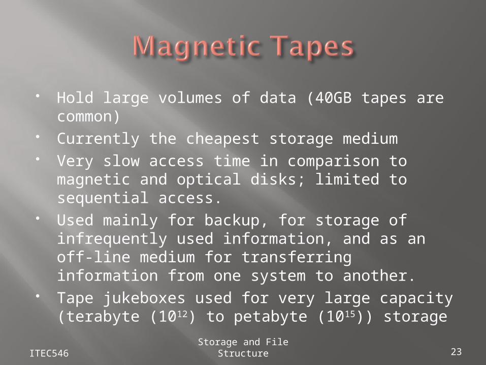
Hold large volumes of data (40GB tapes are common)
Currently the cheapest storage medium Very slow access time in comparison to
magnetic and optical disks; limited to sequential access.
Used mainly for backup, for storage of infrequently used information, and as an off-line medium for transferring information from one system to another.
Tape jukeboxes used for very large capacity (terabyte (1012) to petabyte (1015)) storage
ITEC546 Storage and File Structure 23
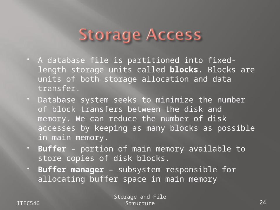
A database file is partitioned into fixed-length storage units called blocks. Blocks are units of both storage allocation and data transfer.
Database system seeks to minimize the number of block transfers between the disk and memory. We can reduce the number of disk accesses by keeping as many blocks as possible in main memory.
Buffer – portion of main memory available to store copies of disk blocks.
Buffer manager – subsystem responsible for allocating buffer space in main memory
ITEC546 Storage and File Structure 24
Programs call on the buffer manager when they need a block from disk The requesting program is given the address of the
block in main memory, if it is already present in the buffer.
If the block is not in the buffer, the buffer manager allocates space in the buffer for the block, replacing (throwing out) some other block, if required, to make space for the new block.
The block that is thrown out is written back to disk only if it was modified since the most recent time that it was written to/fetched from the disk.
Once space is allocated in the buffer, the buffer manager reads in the block from the disk to the buffer, and passes the address of the block in main memory to the requester.
ITEC546 Storage and File Structure 25
Most operating systems replace the block least recently used (LRU)
LRU – use past pattern of block references as a predictor of future references
Queries have well-defined access patterns (such as sequential scans), and a database system can use the information in a user’s query to predict future referencesLRU can be a bad strategy for certain access patterns involving repeated scans of data
Mixed strategy with hints on replacement strategy provided by the query optimizer is preferable
ITEC546 Storage and File Structure 26
Pinned block – memory block that is not allowed to be written back to disk.
Toss-immediate strategy – frees the space occupied by a block as soon as the final tuple of that block has been processed
Most recently used (MRU) strategy – system must pin the block currently being processed. After the final tuple of that block has been processed, the block is unpinned, and it becomes the most recently used block.
Buffer manager can use statistical information regarding the probability that a request will reference a particular relation E.g., the data dictionary is frequently accessed. Heuristic:
keep data-dictionary blocks in main memory buffer
ITEC546 Storage and File Structure 27
The database is stored as a collection of files. The blocks or pages of each file contain a sequence of records. A record is a sequence of fields, e.g. a tuple.
One approach:
assume record size is fixed each file has records of one particular type only different files are used for different relations
This case is easiest to implement; will consider
variable length records later.
ITEC546 Storage and File Structure 28
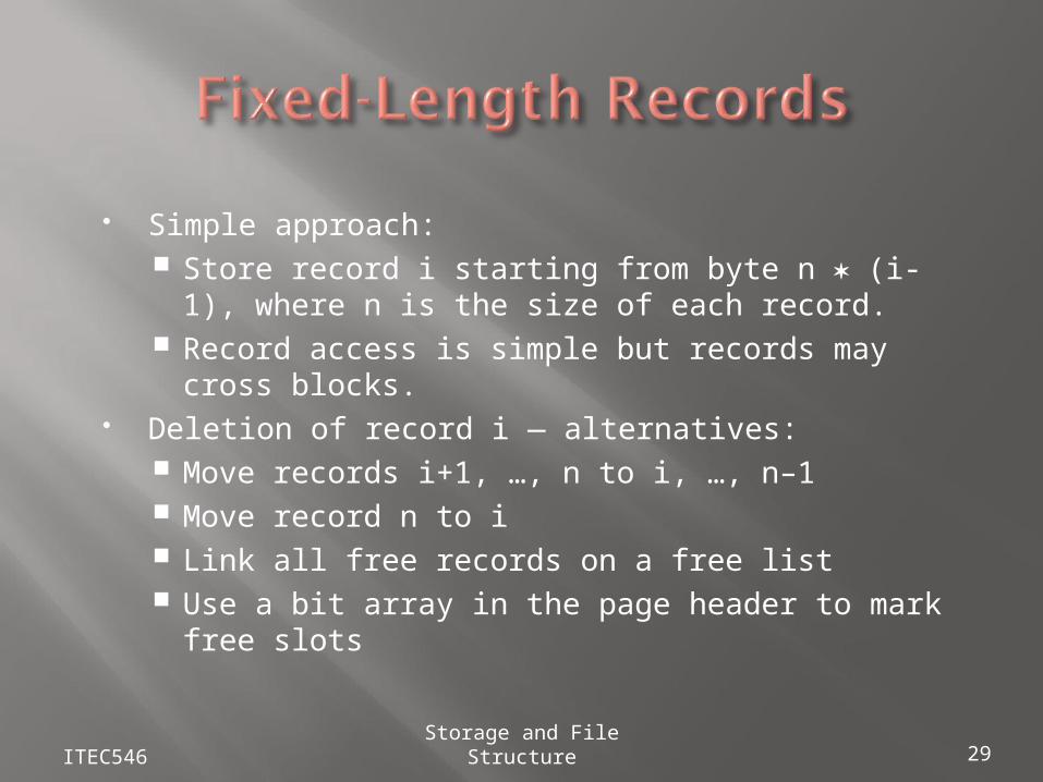
Simple approach: Store record i starting from byte n (i-1), where
n is the size of each record. Record access is simple but records may cross
blocks. Deletion of record i — alternatives:
Move records i+1, …, n to i, …, n–1 Move record n to i Link all free records on a free list Use a bit array in the page header to mark free
slots
ITEC546 Storage and File Structure 29
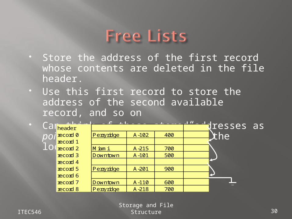
Store the address of the first record whose contents are deleted in the file header.
Use this first record to store the address of the second available record, and so on
Can think of these stored addresses as pointers since they “point” to the location of a record.
ITEC546 Storage and File Structure 30
headerrecord 0 Perryridge A-102 400record 1record 2 Miami A-215 700record 3 Downtown A-101 500record 4record 5 Perryridge A-201 900record 6record 7 Downtown A-110 600record 8 Perryridge A-218 700
More space efficient representation: reuse space for normal attributes of free records to store pointers. (No pointers stored in in-use records.)
Dangling pointers occur if we move or delete a record to which another record contains a pointer; that pointer no longer points to the desired record.
Avoid moving or deleting records that are pointed to by other records; such records are pinned.
ITEC546 Storage and File Structure 31
Each page has a header containing a bit array
If slot n is free the nth bit of the header is set to 0, otherwise 1
Easier to maintain than a free list
ITEC546 Storage and File Structure 32
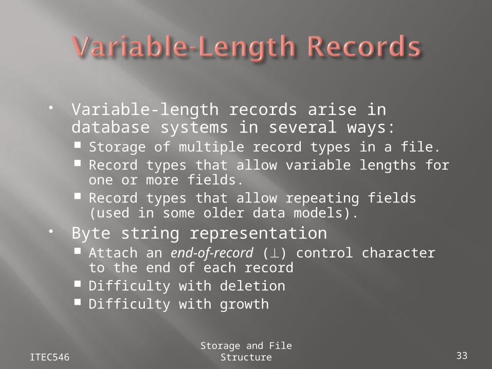
Variable-length records arise in database systems in several ways: Storage of multiple record types in a file. Record types that allow variable lengths for one or
more fields. Record types that allow repeating fields (used in
some older data models). Byte string representation
Attach an end-of-record () control character to the end of each record
Difficulty with deletion Difficulty with growth
ITEC546 Storage and File Structure 33
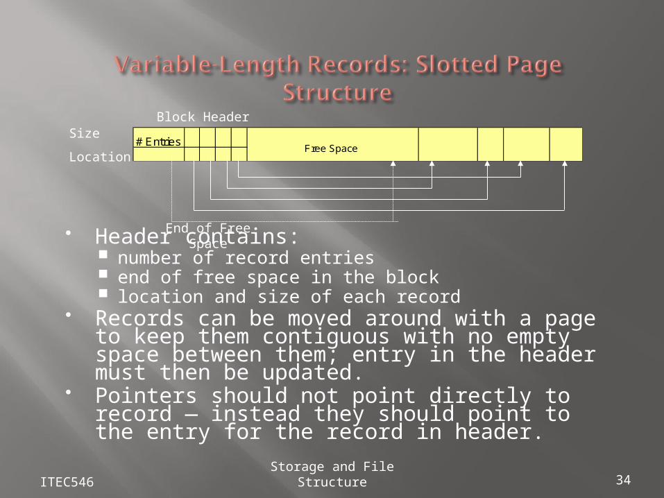
Header contains: number of record entries end of free space in the block location and size of each record
Records can be moved around with a page to keep them contiguous with no empty space between them; entry in the header must then be updated.
Pointers should not point directly to record — instead they should point to the entry for the record in header.
ITEC546 Storage and File Structure 34
# EntriesFree Space
Block HeaderSize
Location
End of Free Space
ITEC546 Storage and File Structure 35
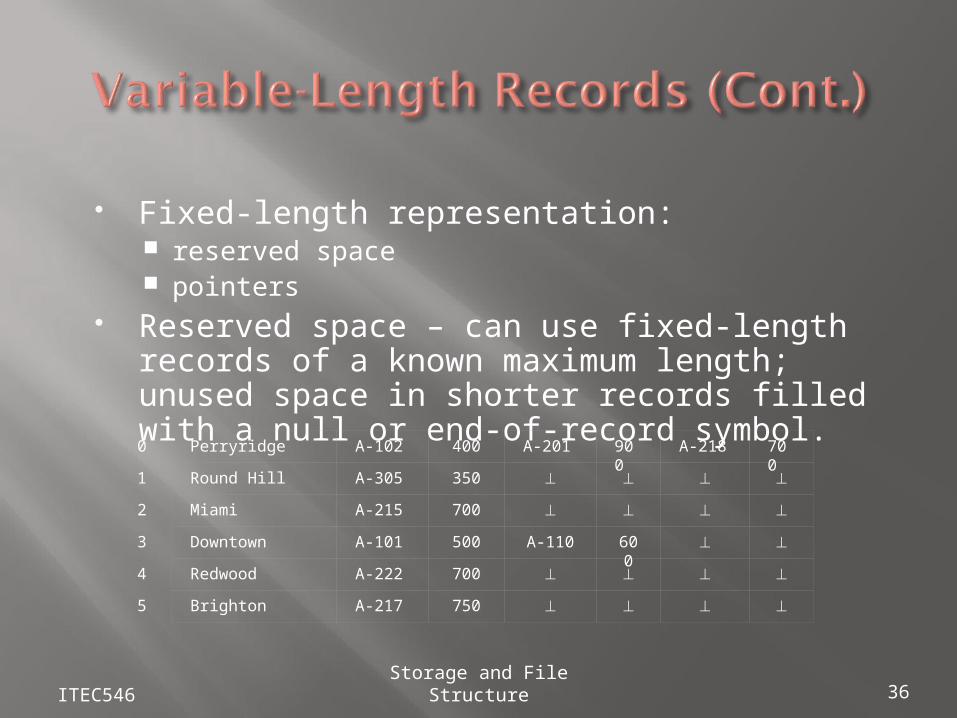
Fixed-length representation: reserved space pointers
Reserved space – can use fixed-length records of a known maximum length; unused space in shorter records filled with a null or end-of-record symbol.
ITEC546 Storage and File Structure 36
0
1
2
3
4
5
Perryridge A-102 400 A-201 900 A-218 700
Round Hill A-305 350
Miami A-215 700
Downtown A-101 500 A-110 600
Redwood A-222 700
Brighton A-217 750
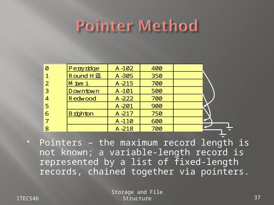
Pointers – the maximum record length is not known; a variable-length record is represented by a list of fixed-length records, chained together via pointers.
ITEC546 Storage and File Structure 37
0 Perryridge A-102 4001 Round Hill A-305 3502 Miami A-215 7003 Downtown A-101 5004 Redwood A-222 7005 A-201 9006 Brighton A-217 7507 A-110 6008 A-218 700
Disadvantage to pointer structure; space is wasted in all records except the first in a chain.
Solution is to allow two kinds of blocks in file: Anchor blocks – contain the first records of
chains Overflow blocks – contain records other than
those that are the first records of chains.
Storage and File Structure 38
ITEC546
Oracle has its own buffer management, with complex policies
Oracle doesn’t rely on the underlying operating system’s file system
A database in Oracle consists of tablespaces: System tablespace: contains catalog meta-data User data tablespaces
The space in a tablespace is divided into segments: Data segment Index segment Temporary segment (for sort operations) Rollback segment (for processing transactions)
Segments are divided into extents, each extent being a set of contiguous database blocks. A database block need not be the same size of an
operating system block, but is always a multiple
ITEC546 Storage and File Structure
A standard table is organized in a heap (no sequence is imposed) Partitioning of tables is possible for optimization
Range partitioning (e.g by dates) Hash partitioning Composite partitioning
Table data in Oracle can also be (multitable) clustered One may tune the clusters to significantly improve the efficiency
of query to frequently used joins. Hash file organization (to be studied in the sequel) is also possible
for fetching the appropriate cluster
A database can be tuned by an appropriate choice for the organization of data: Choosing partitions Appropriate choice of clusters Hash or sequential
Tuning makes the difference in big (real) databases!
ITEC546 Storage and File Structure
ITEC546 Storage and File Structure 41