Embed Size (px)
Citation preview
1
Autonomous Sample Retriever By:
Richard Chaparro, Charles Rodosevich and Jose Ramos Colorado State University-Pueblo
Pueblo, CO
Abstract
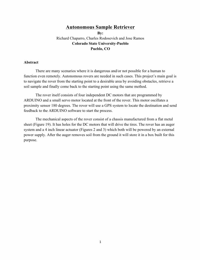
There are many scenarios where it is dangerous and/or not possible for a human to function even remotely. Autonomous rovers are needed in such cases. This project’s main goal is to navigate the rover from the starting point to a desirable area by avoiding obstacles, retrieve a soil sample and finally come back to the starting point using the same method.
The rover itself consists of four independent DC motors that are programmed by ARDUINO and a small servo motor located at the front of the rover. This motor oscillates a proximity sensor 180 degrees. The rover will use a GPS system to locate the destination and send feedback to the ARDUINO software to start the process.
The mechanical aspects of the rover consist of a chassis manufactured from a flat metal sheet (Figure 19). It has holes for the DC motors that will drive the tires. The rover has an auger system and a 4 inch linear actuator (Figures 2 and 3) which both will be powered by an external power supply. After the auger removes soil from the ground it will store it in a box built for this purpose.
2
1. Introductory Material
1.1 Acknowledgements This senior design project will be mainly advised by Dr. Ding Yuan, Professor of Engineering at CSU-Pueblo for control systems guidance, and Dr. Jane Fraser, Chair of the Engineering Department at CSU-Pueblo for final project guidance, direction, and grading. Throughout the progression of the project, other guidance and advisement will be needed in the areas of project management, robotics, digital and analog electronics, machining, fabrication, and general engineering. The project requires the guidance of Dr. Huseyin Sarper, Professor of Engineering at CSU-Pueblo for his expertise in project management, Dr. Nebosja Jaksic, Professor of Engineering at CSU-Pueblo for his extensive knowledge in robotics, Dr. Jude DePalma, Professor of Engineering at CSU-Pueblo for his extensive knowledge of digital and analog electronics, Dr. Paudel for his background in mechatronics aspects, as well as Mr. Paul Wallace who is an proficient machinist with a vast amount of knowledge in general engineering studies. Joe Datillo for his help in programming the microcontroller and in general advice for the electrical components. 1.2 Problem Statement Design an autonomous rover with the mechanics to effectively retrieve and store a small geological sample. The design team will then implement this design through fabrication into physical elements that will be built into a completed mechanical rover. The design team will then design a control system to efficiently run all on-board electronic components using a specified power source. The team will troubleshoot each system separately, thoroughly identifying and solving each problem occurring. Both systems will be integrated together and be checked for overall system efficiency and errors. The entire system will then be subject to an overall troubleshooting process where each occurring problem will be thoroughly handled. 1.3 General Solution Approach In order to achieve the most simple and efficient design, group decisions have been made that the rover should have an auger system and a linear actuator powered by an external power supply. The rover should be able to locate the desired area using data collected from a GPS system where the sample is and afterwards retrieve the sample using the auger to dig a hole and retrieve a sample and dump it in the on board trough. The rover will then return to the origin while avoiding any kind of obstacles on the way by using an ultrasonic sensor. 1.4 Operating Environment The rover will be applicable in any uninhabitable environment that may be a danger to human life or contact. These areas may be indoors or outdoors according to the requirements of retrieving a specified sample. For the demonstration of the designed rover, a local area outside of the CSU-Pueblo technology building will be used. 1.5 Intended User(s) or Use(s) The rover is applicable to emergency technicians for environmental hazards and astronauts for Mars and Moon missions where the environment is inaccessible. Other applications include areas dangerous for human contact, radiated and polluted areas, as well as
3
clean rooms and many more. The rover has no need of an onsite user, because the rover is completely autonomous; it does require someone capable of writing a program with the physical requirements of the applications needed for each case. 1.6 Expected End-Product The expected end-product should be a professional, autonomous prototype that can meet all the criteria given, a SolidWorks drawing that describes all the physical details of the rover, circuit designs, test plans, test results, product report, log book, project poster, copies of project report and an electronic copy of the project report. The expected delivery date is April 20, 2012.
1.7 Assumptions and Limitations The table below shows the assumptions and limitations for the rover based on past experiences.
Table 1. Assumptions and Limitations
Assumptions Limitations The auger should be able to penetrate the surface of the desired area.
The area chose to penetrate should be soft enough to allow the auger system to penetrate.
The rover will be heavy enough to overcome the force applied on the surface by the linear actuator.
The materials used should be light, durable and weather resistance.
The data collected by the GPS will be accurate. The rover cannot be touched after the program has started.
The area chose to get our geological sample will consist of non-solids samples.
Not able to retrieve solid samples.
2. Approach
2.1 Functional Requirements Requirements are listed below, having in mind that the rover itself should be able to complete all the tasks listed in the goal. If any of these requirements fail then the goal also fails.
A. Be completely autonomous B. Retrieve the desired sample C. Avoid obstacles from the origin to the destination D. Avoid obstacles from the destination to the origin E. Stored sample appropriately in “trough” so it will not spilt
2.2 Constraint Considerations The rover should be light enough to be easily driven by the motors. The tires on the rover
should be all-terrain for all different applications that the rover may encounter. The auger system and the linear actuator will penetrate the surface without lifting the rover and the power supplies should be able to endure the full trip, while running all electrical components.
4
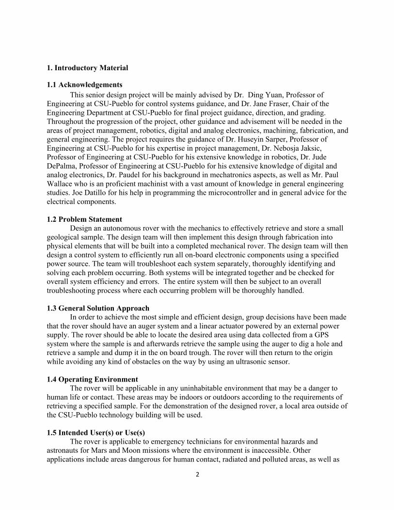
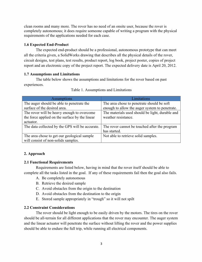
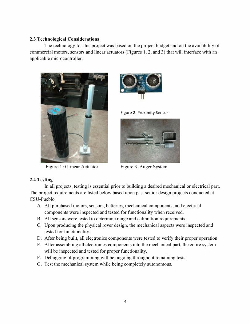
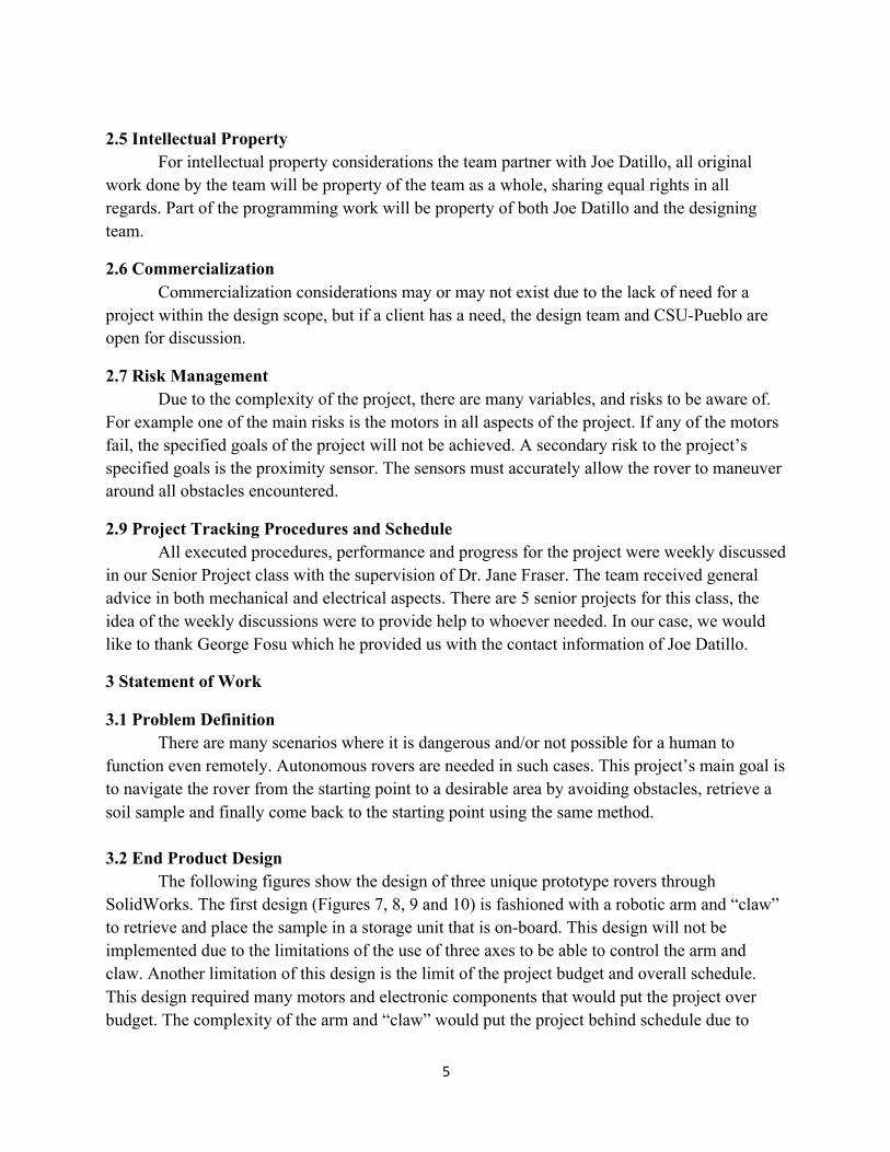
2.3 Technological Considerations The technology for this project was based on the project budget and on the availability of commercial motors, sensors and linear actuators (Figures 1, 2, and 3) that will interface with an applicable microcontroller.
Figure 1.0 Linear Actuator Figure 3. Auger System 2.4 Testing In all projects, testing is essential prior to building a desired mechanical or electrical part. The project requirements are listed below based upon past senior design projects conducted at CSU-Pueblo.
A. All purchased motors, sensors, batteries, mechanical components, and electrical components were inspected and tested for functionality when received.
B. All sensors were tested to determine range and calibration requirements. C. Upon producing the physical rover design, the mechanical aspects were inspected and
tested for functionality. D. After being built, all electronics components were tested to verify their proper operation. E. After assembling all electronics components into the mechanical part, the entire system
will be inspected and tested for proper functionality. F. Debugging of programming will be ongoing throughout remaining tests. G. Test the mechanical system while being completely autonomous.
Figure 2. Proximity Sensor
5
2.5 Intellectual Property For intellectual property considerations the team partner with Joe Datillo, all original work done by the team will be property of the team as a whole, sharing equal rights in all regards. Part of the programming work will be property of both Joe Datillo and the designing team.
2.6 Commercialization Commercialization considerations may or may not exist due to the lack of need for a project within the design scope, but if a client has a need, the design team and CSU-Pueblo are open for discussion.
2.7 Risk Management Due to the complexity of the project, there are many variables, and risks to be aware of. For example one of the main risks is the motors in all aspects of the project. If any of the motors fail, the specified goals of the project will not be achieved. A secondary risk to the project’s specified goals is the proximity sensor. The sensors must accurately allow the rover to maneuver around all obstacles encountered.
2.9 Project Tracking Procedures and Schedule All executed procedures, performance and progress for the project were weekly discussed
in our Senior Project class with the supervision of Dr. Jane Fraser. The team received general advice in both mechanical and electrical aspects. There are 5 senior projects for this class, the idea of the weekly discussions were to provide help to whoever needed. In our case, we would like to thank George Fosu which he provided us with the contact information of Joe Datillo.
3 Statement of Work
3.1 Problem Definition There are many scenarios where it is dangerous and/or not possible for a human to
function even remotely. Autonomous rovers are needed in such cases. This project’s main goal is to navigate the rover from the starting point to a desirable area by avoiding obstacles, retrieve a soil sample and finally come back to the starting point using the same method. 3.2 End Product Design
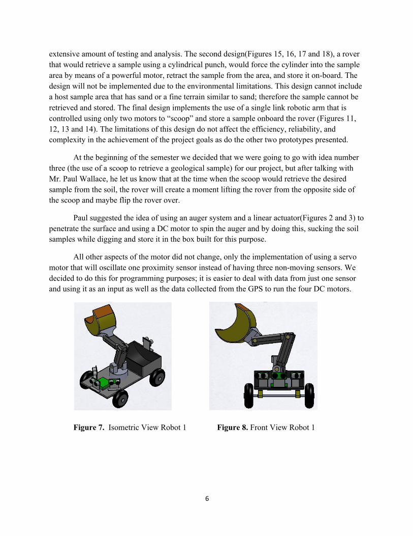
The following figures show the design of three unique prototype rovers through SolidWorks. The first design (Figures 7, 8, 9 and 10) is fashioned with a robotic arm and “claw” to retrieve and place the sample in a storage unit that is on-board. This design will not be implemented due to the limitations of the use of three axes to be able to control the arm and claw. Another limitation of this design is the limit of the project budget and overall schedule. This design required many motors and electronic components that would put the project over budget. The complexity of the arm and “claw” would put the project behind schedule due to
6
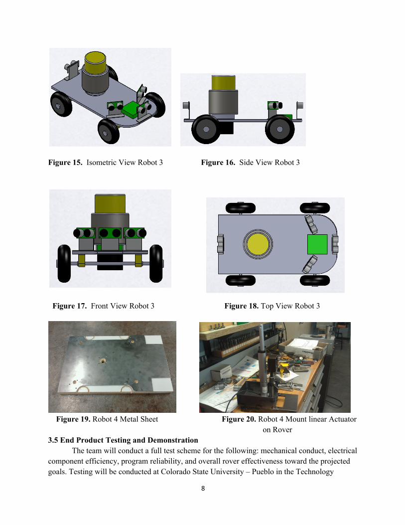
extensive amount of testing and analysis. The second design(Figures 15, 16, 17 and 18), a rover that would retrieve a sample using a cylindrical punch, would force the cylinder into the sample area by means of a powerful motor, retract the sample from the area, and store it on-board. The design will not be implemented due to the environmental limitations. This design cannot include a host sample area that has sand or a fine terrain similar to sand; therefore the sample cannot be retrieved and stored. The final design implements the use of a single link robotic arm that is controlled using only two motors to “scoop” and store a sample onboard the rover (Figures 11, 12, 13 and 14). The limitations of this design do not affect the efficiency, reliability, and complexity in the achievement of the project goals as do the other two prototypes presented.
At the beginning of the semester we decided that we were going to go with idea number three (the use of a scoop to retrieve a geological sample) for our project, but after talking with Mr. Paul Wallace, he let us know that at the time when the scoop would retrieve the desired sample from the soil, the rover will create a moment lifting the rover from the opposite side of the scoop and maybe flip the rover over.
Paul suggested the idea of using an auger system and a linear actuator(Figures 2 and 3) to penetrate the surface and using a DC motor to spin the auger and by doing this, sucking the soil samples while digging and store it in the box built for this purpose.
All other aspects of the motor did not change, only the implementation of using a servo motor that will oscillate one proximity sensor instead of having three non-moving sensors. We decided to do this for programming purposes; it is easier to deal with data from just one sensor and using it as an input as well as the data collected from the GPS to run the four DC motors.
Figure 7. Isometric View Robot 1 Figure 8. Front View Robot 1
7
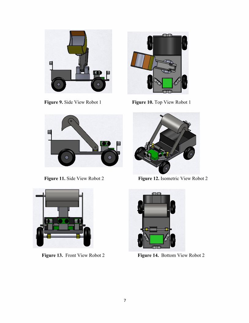
Figure 9. Side View Robot 1 Figure 10. Top View Robot 1
Figure 11. Side View Robot 2 Figure 12. Isometric View Robot 2
Figure 13. Front View Robot 2 Figure 14. Bottom View Robot 2
8
Figure 15. Isometric View Robot 3 Figure 16. Side View Robot 3
Figure 19. Robot 4 Metal Sheet Figure 20. Robot 4 Mount linear Actuator
on Rover 3.5 End Product Testing and Demonstration
The team will conduct a full test scheme for the following: mechanical conduct, electrical component efficiency, program reliability, and overall rover effectiveness toward the projected goals. Testing will be conducted at Colorado State University – Pueblo in the Technology
Figure 17. Front View Robot 3 Figure 18. Top View Robot 3
9
building where certain variables of the project to be controlled and assessed. Once all problems that arise and variables involved are taken into consideration, the team will conduct a full demonstration. Each project goal and sub-goal will be demonstrated to be sufficiently achieved to the engineering faculty and other Colorado State University – Pueblo students. The demonstration is also open to the public, perspective clients, and engineering related businesses. The demonstration will be conducted outside of the technology building in a setting that will be formatted to the controls of the project goals.
3.7 Presentation Poster The project design team will create a presentation board summarizing the overall project goals and efficiency of the rover. This presentation board will be put on display in the hallway(s) of the technology building at Colorado State University – Pueblo.
4 Cost & Resources 4.1 Cost Analysis
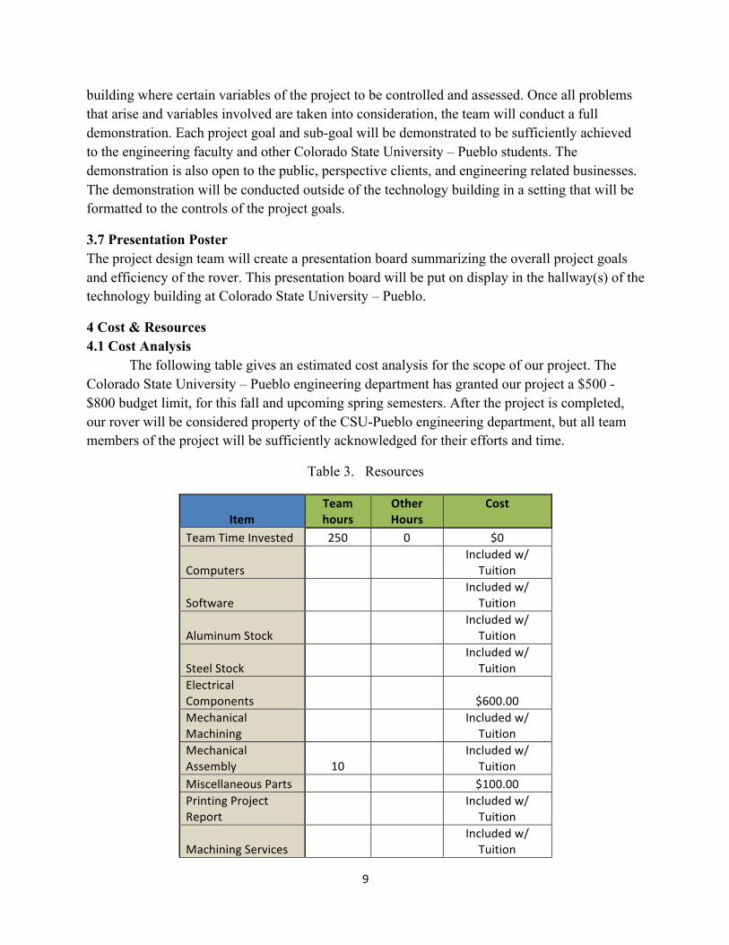
The following table gives an estimated cost analysis for the scope of our project. The Colorado State University – Pueblo engineering department has granted our project a $500 - $800 budget limit, for this fall and upcoming spring semesters. After the project is completed, our rover will be considered property of the CSU-Pueblo engineering department, but all team members of the project will be sufficiently acknowledged for their efforts and time.
Table 3. Resources
Item Team hours
Other Hours
Cost
Team Time Invested 250 0 $0
Computers
Included w/ Tuition
Software
Included w/ Tuition
Aluminum Stock
Included w/ Tuition
Steel Stock
Included w/ Tuition
Electrical Components
$600.00
Mechanical Machining
Included w/ Tuition
Mechanical Assembly 10
Included w/ Tuition
Miscellaneous Parts
$100.00 Printing Project Report
Included w/ Tuition
Machining Services
Included w/ Tuition
10
Totals
$700.00