Embed Size (px)
Citation preview
By Authority OfTHE UNITED STATES OF AMERICA
Legally Binding Document
By the Authority Vested By Part 5 of the United States Code § 552(a) and Part 1 of the Code of Regulations § 51 the attached document has been duly INCORPORATED BY REFERENCE and shall be considered legally binding upon all citizens and residents of the United States of America. HEED THIS NOTICE: Criminal penalties may apply for noncompliance.
Official Incorporator:THE EXECUTIVE DIRECTOROFFICE OF THE FEDERAL REGISTERWASHINGTON, D.C.
Document Name:
CFR Section(s):
Standards Body:
e

Voluntary Specifications for Aluminum, Vinyl (PVC) and Wood Windows and Glass Doors
Errata 5/2005
Reprinted 5/2005
AAMA/NWWDA 101/I.S.2-97
Copyright by the American Architectural Manufacturers Association (AAMA). This document was purchased by Carl Malamud of Public.Resource.Org on April 20, 2012. It may not be reproduced, republished or distributed in any format without the express written consent of AAMA.
This document was developed and researched by representative members of AAMA and WDMA as advisory information and published as a public service. AAMA and WDMA disclaim all liability for the use, application or adaptation of materials published herein
Copyright © 2005 – Co-Published by:
American Architectural Manufacturers Association 1827 Walden Office Square, Suite 550, Schaumburg, Illinois 60173 Phone: (847) 303-5664 Fax: (847) 303-5774 E-Mail: [email protected]
Window and Door Manufacturers Association – formerly NWWDA 1400 East Touhy Avenue, Suite 470, Des Plaines, Illinois 60018 Phone: (847) 299-5200 Fax: (847) 299-1286 E-mail: [email protected]
TABLE OF CONTENTS ERRATA (5/18/05) PREFACE ................................................................................................................................................................1 FOREWORD ............................................................................................................................................................2 SECTION 1 GENERAL REQUIREMENTS .................................................................................................................3 1.1 GENERAL ..........................................................................................................................................................3 1.2 TERMINOLOGY..................................................................................................................................................3 SECTION 2 SPECIFIC REQUIREMENTS ..................................................................................................................5 2.1 TESTING REQUIREMENTS ................................................................................................................................7 2.2 SPECIFIC PRODUCT PERFORMANCE REQUIREMENTS ................................................................................. 10 2.2.1 SINGLE, DOUBLE, AND TRIPLE HUNG WINDOWS ....................................................................................... 10 2.2.2 HORIZONTAL SLIDING WINDOWS................................................................................................................ 12 2.2.3 VERTICAL SLIDING WINDOWS..................................................................................................................... 13 2.2.4 AWNING, HOPPER, PROJECTED WINDOWS ................................................................................................ 14 2.2.5 CASEMENT WINDOWS ................................................................................................................................. 17 2.2.6 VERTICALLY OR HORIZONTALLY PIVOTED WINDOWS............................................................................... 19 2.2.7 SIDE-HINGED (INSWINGING) WINDOWS ...................................................................................................... 21 2.2.8 TOP-HINGED WINDOWS ............................................................................................................................... 22 2.2.9 FIXED WINDOWS .......................................................................................................................................... 23 2.2.10 DUAL ACTION WINDOWS ........................................................................................................................... 24 2.2.11 BASEMENT WINDOWS ............................................................................................................................... 25 2.2.12 HINGED EGRESS WINDOWS ...................................................................................................................... 26 2.2.13 GREENHOUSE WINDOWS .......................................................................................................................... 27 2.2.14 JALOUSIE WINDOWS ................................................................................................................................. 28 2.2.15 JAL-AWNING WINDOWS............................................................................................................................. 28 2.2.16 TROPICAL AWNING WINDOWS .................................................................................................................. 29 2.2.17 HINGED GLASS DOORS ............................................................................................................................. 29 2.2.18 DUAL ACTION HINGED GLASS DOORS ..................................................................................................... 30 2.2.19 SLIDING GLASS DOORS ............................................................................................................................. 32 SECTION 3 MATERIAL AND COMPONENT REQUIREMENTS ................................................................................ 33 3.1 MATERIALS ..................................................................................................................................................... 33 3.2 CONSTRUCTION.............................................................................................................................................. 35 3.3 FINISHES ......................................................................................................................................................... 36 3.4 INSECT SCREENS ........................................................................................................................................... 36 3.5 DRAWINGS AND INSTALLATION DETAILS ..................................................................................................... 36 3.6 GLASS AND GLAZING MATERIALS................................................................................................................. 36 3.7 VENETIAN BLINDS IN A DUAL GLAZED WINDOW .......................................................................................... 37 3.8 REFERENCE STANDARDS .............................................................................................................................. 38 SECTION 4 OPTIONAL PERFORMANCE GRADES ................................................................................................ 42 4.1 GENERAL ........................................................................................................................................................ 42 4.2 CRITERIA......................................................................................................................................................... 42 4.3 WATER RESISTANCE TEST ............................................................................................................................ 43 4.4 UNIFORM LOAD TESTS ................................................................................................................................... 43 4.5 IDENTIFICATION.............................................................................................................................................. 43 APPENDIX A - CORNER WELD TEST PROCEDURE.............................................................................................. 44 APPENDIX B - RELATED SUBJECTS .................................................................................................................... 44 APPENDIX C - ROUNDING PROCEDURE FOR PRODUCT TESTING...................................................................... 56 APPENDIX D - GLOSSARY .................................................................................................................................... 57 REFERENCE STANDARD SOURCES .................................................................................................................... 62
Copyright by the American Architectural Manufacturers Association (AAMA). This document was purchased by Carl Malamud of Public.Resource.Org on April 20, 2012. It may not be reproduced, republished or distributed in any format without the express written consent of AAMA.
101/I.S.2-97 Errata (5/18/05)
ERRATA DATE: MAY 18, 2005 CODE: AAMA/NWWDA 101/I.S.2-97 TITLE: Voluntary Specifications for Aluminum, Vinyl (PVC) and Wood Windows and Glass Doors
***THESE REVISIONS ARE EDITORIAL AND SIMPLY CLARIFY CONTENT*** GLOBAL EDITS • This document is no longer ANSI approved. “ANSI” and “American National Standard” have been removed
throughout the document in reference to the 1997 version of this standard. • Punctuation, capitalization, spelling, spacing and grammar errors were corrected throughout. • General table format inconsistencies were corrected throughout. • General section heading format inconsistencies were corrected throughout. • The publication year in the title of AAMA reference documents was changed to two-digit year designations for
consistency. MEASUREMENT EDITS • Abbreviation for inch (in) was used throughout. • Abbreviation for feet (ft) was used throughout. • Abbreviation for pounds (lbs) was used throughout. • Abbreviation for inch per foot (in/ft) was used throughout. • Abbreviation for mm per meter (mm/m) was used throughout. SPECIFIC EDITS PREFACE & REFERENCE STANDARD SOURCES The AAMA address was revised from Suite #104 to Suite #550. FOREWARD The note discussing an American National Standard was removed. SECTION 2, TABLE 2.1 Window/Door Designation “Top Hinged (Inswinging) Windows” was changed to: Top-Hinged Windows to appropriately correlate to the associated section 2.2.8. SECTION 2.1.8 Revision was made as follows: …AAMA 1302.5 or AAMA 2300 (formerly CAWM 300) …AAMA 1303.5 or AAMA 2301 (formerly CAWM 301) Reason: AAMA 2300 and AAMA 2301 were removed because they were never completed and published. SECTION 2.2.1.4.2 ANSI was removed from the document title ANSI/AAMA 1002.10 because this document is no longer ANSI approved.
Copyright by the American Architectural Manufacturers Association (AAMA). This document was purchased by Carl Malamud of Public.Resource.Org on April 20, 2012. It may not be reproduced, republished or distributed in any format without the express written consent of AAMA.

101/I.S.2-97 Errata (5/18/05)
SECTION 2.2.4.5.6 40 lbf-in (4.6 N·m) was changed to: 40 lbf•in (4.6 N•m) SECTION 3.1.5 TABLE, SECOND COLUMN HEADING Reinforcement Exposure was changed to: Fastener Exposure APPENDIX B, AIR LEAKAGE a) cubic feet per minute per square foot of area (ft3/min/ft2) was changed to: cubic feet per minute per square foot of area (cfm/ft2) b) cubic meters per hour per square meter of area (m3/h/m2) was changed to: cubic meters per hour per square meter of area (m3/h•m2) APPENDIX B, WATER RESISTANCE 5 gallons per square foot per hour (3.40 L/min/M2) was changed to: 5 gal/hr•ft2 (3.40L/min•m2) APPENDIX C, STEP 2 a) CFM/ft2 to m3/hr/m2 was changed to: cfm/ft2 to m3/hr•m2
b) 1.28 m3/hr/m2 was changed to: 1.28 m3/hr•m2 c) 1 m3/hr/m2 was changed to: 1 m3/hr•m2
If there are any questions on the editorial revisions made to AAMA/NWWDA 101/I.S.2-97, please contact the AAMA Documents & Standards Coordinator to discuss at: (847) 303-5859 x262.
Copyright by the American Architectural Manufacturers Association (AAMA). This document was purchased by Carl Malamud of Public.Resource.Org on April 20, 2012. It may not be reproduced, republished or distributed in any format without the express written consent of AAMA.

PREFACE
1
This standard establishes minimum requirements for aluminum, vinyl (PVC) and wood windows and glass doors. It consists of four sections and an Appendix. SECTION 1 covers the general definitions and terminology applicable to all windows and doors. SECTION 2 contains the specific requirements for product performance. These requirements provide a gateway or passport into one of the five product classifications. There are four mandatory primary performance requirements. They are: 1) Structural adequacy to withstand wind loads, 2) Resistance to water leakage, 3) Resistance to air leakage, and 4) Forced-Entry Resistance. Levels of performance are set forth for each window or door type covered by the standard. Also included as optional primary performance requirements are acoustical performance, condensation resistance and thermal transmittance. In addition to the primary performance requirements there are specific product performance requirements appropriate to each type of window and door. These include requirements for test specimens, hardware, deflection under concentrated and torsional loads, deglazing and life cycle testing. SECTION 3 presents the material and component requirements applicable to all windows and doors. These include requirements for alloys, fasteners, hardware, construction, finishes, glass and glazing. Standards referenced in this document are also included as a list of references in this section. SECTION 4 contains optional performance grades which make it possible for the specifier to require higher uniform load structural test pressures and higher water resistance test pressures than those contained in Section 2. Use of products in the optional performance grades is desirable where severe weather conditions or wind loadings are encountered. The APPENDIX, although not a part of this AAMA/NWWDA standard, contains much information on materials, construction, installation, wind loads, water resistance, air leakage, condensation and heat transmission and a glossary that will be helpful to the specifier in the selection and specification of windows and doors. The addition of architectural grade windows in 1993 represented a major revision to this standard. Architectural windows were originally covered in AAMA GS-001, "Voluntary Guide Specifications for Aluminum Architectural Windows," published in 1984.
Architectural windows and sliding glass doors have the same design pressure and structural test pressure minimum requirements as heavy commercial products. Generally higher performance requirements have been specified for water resistance and air leakage than those required by the heavy commercial grade. A limit to deflection of L/175 under the uniform load test has also been established for architectural windows and doors. Architectural windows and doors are required to also pass the life cycle testing in AAMA 910, "Voluntary 'Life Cycle' Specifications and Test Methods for Architectural Grade Windows and Sliding Glass Doors" in addition to the unglazed component structural tests as required for HC products. This 1997 AAMA/NWWDA standard is applicable for use in testing and certifying aluminum, vinyl and wood fenestration products. This standard represents the continuing development of a nationally accepted performance standard for all fenestration products. This revision combined with a restructuring of the document format to promote clarity and ease of use are indicative of the document authors' continued commitment to improvement in fenestration product performance. This standard defines requirements for five classes of windows and glass doors. The classes are: Residential (R), Light Commercial (LC), Commercial (C), Heavy Commercial (HC) and Architectural (AW). Performance is designated by a number which follows the type and class designation. For example, a Double-Hung Residential window may be designated H-R15. The number establishes the design pressure, in this case 15 psf. The structural test pressure for all windows and doors is 50% higher than the design pressure which, for the example H-R15 window, would be 22.5 psf. Minimum design pressures, structural test pressures, and water resistance test pressures for the five classes in pounds per square foot are: Window and Door
Classes Design
Pressure Structural Test
Pressure Water Resistance
Test Pressure Residential
Light Commercial Commercial
Heavy Commercial Architectural
15 25 30 40 40
22.5 37.5 45.0 60.0 60.0
2.86 3.75 4.50 6.00 8.00
NOTE: The Preface, Foreword, notes included in the document, Appendix B, Appendix C, and Appendix D are not part of the standard.
Copyright by the American Architectural Manufacturers Association (AAMA). This document was purchased by Carl Malamud of Public.Resource.Org on April 20, 2012. It may not be reproduced, republished or distributed in any format without the express written consent of AAMA.
FOREWORD
2
AAMA/NWWDA 101/I.S.2-97
Voluntary Specifications for Aluminum, Vinyl (PVC) and Wood Windows and Glass Doors
FOREWORD (This Foreword is not a part of the Voluntary Specifications for Aluminum, Vinyl (PVC) and Wood Windows and Glass Doors, AAMA/NWWDA 101/I.S.2-97). This document is a merger of two nationally recognized, material specific performance standards (AAMA 101-93 and NWWDA I.S.2-93). It also includes specifications from NWWDA I.S.3 and I.S.8. The new format allows the future inclusion of other materials as recognized performance standards are established. HOW TO USE THESE SPECIFICATIONS To simplify the writing of specifications for aluminum, vinyl (PVC) and wood windows and glass doors, AAMA and NWWDA have prepared a "Short Form Specification" which is recommended for use whenever possible. It may be used for most common types and classes of aluminum, vinyl (PVC) and wood windows and glass doors by merely inserting the applicable specification designation(s). For a complete "Long Form" specification, combine Sections 1 and 3 with one or more of the specifications in Sections 2 or 4. SHORT FORM SPECIFICATION All aluminum and/or vinyl (PVC) and/or wood windows and glass doors shall conform to the (see Note below) voluntary specification(s) in AAMA/NWWDA 101/I.S.2-97, be labeled with the "AAMA" or "WDMA Hallmark" label, have the sash arrangement(s) and be of the size(s) shown on the drawings and be as manufactured by or or approved equal. Note to the Specification Writer: Insert type, class and design pressure of window or door desired by specification designation such as HS -R15 for horizontal sliding windows for residential-type buildings, AP-C30 for projected windows in commercial-type construction, TH-HC40 for top hinged windows in heavy commercial-type buildings, etc. For specification designations, see list in Table of Contents and detailed requirements in Sections 2 and 4 of the Master Specification. Product designation codes are explained in Section 1.2.
Copyright by the American Architectural Manufacturers Association (AAMA). This document was purchased by Carl Malamud of Public.Resource.Org on April 20, 2012. It may not be reproduced, republished or distributed in any format without the express written consent of AAMA.
SECTION 1 GENERAL REQUIREMENTS
3
NOTE: This section contains general information applicable to single and dual windows and glass doors, and is to be used in conjunction with Sections 2 and 3. 1.1 GENERAL This voluntary specification covers requirements for single and dual windows and glass doors for new construction and replacement applications. For further information, refer to the AAMA Window Selection Guide and the Window Selection Section of NWWDA I.S.2. 1.2 TERMINOLOGY As used in this specification, the following definitions and designations apply: 1.2.1 PRODUCT DESIGNATIONS Window and door products included in this document are designated by a four-part code which includes product type, performance class, performance grade and maximum size tested. The format for product designation is:
HS - LC 25 48x76 Maximum Size Tested Width x Height
Performance Grade
Performance Class
Product Type
NOTE: An asterisk (*) added to the performance grade indicates the size tested for the optional performance grade was smaller than the minimum test size for the original product type and class. For example, if a H-HC40 product which has passed the General Requirements of Section 1, the Gateway Performance Requirements in Table 2.1, the Specific Performance Requirements of Sections 2.2, and the Material and Component Requirements of Section 3, is then tested and passes the performance requirements for an Optional Performance Grade 60 according to Section 4, that product is now identified as a H-HC60 (W x H). If the test size for this product at the HC60 optional performance grade were smaller than that required for an H-HC40 specimen, the new designation would be H-HC60* (W xH). 1.2.1.1 Product Type Each product type and class requires minimum test sizes for entry into the product class.
Window and door product types covered in this document are as follows: AP = Awning, Hopper, Projected Window BW = Basement Windows C = Casement Windows DA = Dual Action Windows DA-HGD = Dual Action Hinged Glass Doors F = Fixed Windows GH = Greenhouse Windows H = Hung Windows (Single, Double, Triple) HE = Hinged Egress Windows HGD = Hinged Glass Doors HP = Horizontally Pivoted Windows HS = Horizontal Sliding Windows J = Jalousie Windows JA = Jal-Awning Windows SHW = Side Hinged Inswinging Windows SGD = Sliding Glass Doors TA = Tropical Awning Windows TH = Top Hinged Windows VP = Vertically Pivoted Windows VS = Vertical Sliding Windows
1.2.1.2 Performance Class Window and door products covered by this document shall be divided into five performance classes as follows: R = Residential LC = Light Commercial C = Commercial HC = Heavy Commercial AW = Architectural
1.2.1.3 Performance Grade Products are designated by the design pressure for which they have been tested in pounds per square foot. The structural test pressure for all products is 1.5 times the design pressure. Each product performance class shall have a minimum performance grade as follows: R = 15 psf (720 Pa) LC = 25 psf (1200 Pa) C = 30 psf (1440 Pa) HC = 40 psf (1920 Pa) AW = 40 psf (1920 Pa)
In addition, products may be tested to optional performance grades higher than the minimum grade in increments of 5 psf (240 Pa). (See Section 4, Optional Performance.) Products which have been tested as dual windows as specified in Section 1.2.2, shall have the code DW added to their product designation after the product type. An example of product designation for a dual window would be: HS-DW-LC25 48x76.
Copyright by the American Architectural Manufacturers Association (AAMA). This document was purchased by Carl Malamud of Public.Resource.Org on April 20, 2012. It may not be reproduced, republished or distributed in any format without the express written consent of AAMA.
4
1.2.1.4 Maximum Size Tested Maximum size tested is required on designations reporting or recording individual product performance. This part of the product designation code should be omitted when specifying products according to this standard. The maximum test size shall be designated by width times (x) height in inches rounded to the nearest inch, for example 48x76. Test size is a critical factor in determining compliance with this standard. Each product type has a defined "gateway" or "passport" set of primary requirements before entry into the product performance class is permitted. One of these gateway requirements is minimum test size. Products must be tested at the minimum test size or a larger specimen size as a condition of entering the class. After passing all of the performance requirements for the product type, class and grade, the product may be designated with the appropriate class, i.e., LC for Light Commercial. This designation shall only be applied to production sizes equal to or smaller than the size tested. There are two options for selection of a product specimen to be tested for Optional Performance Grade Levels: 1) The original Gateway Performance specimen may be tested again to higher grade levels; 2) Another test specimen of similar or smaller size may be tested to the higher grade. If the test specimen is smaller than the Gateway test size, an asterisk (*) shall be appended to the product designation. (See Section 1.2.1.) Persons wishing to prove compliance with both gateway and the optional performance requirements on the same test specimen, shall test a specimen equal to or greater than the minimum test size for that product type.
1.2.2 DUAL WINDOWS A dual window is a window composed of one of the configurations listed in this Section and offered by the manufacturer as a complete factory pre-assembled or integral unit. Operation of the primary and secondary sash shall be completely independent of each other. Dual windows are marketed and tested as integral units. Only units which are tested as an integral product may be certified as dual windows (DW). The primary window may be tested under the appropriate section of this document as a stand alone unit. The secondary window may be tested separately under AAMA 1002.10. If the primary and secondary units are tested independently for purposes of certification, they may be labeled and marketed independently. Dual window configurations include: 1. Interior Primary/Exterior Secondary 2. Exterior Primary/Interior Secondary 3. Interior Primary/Exterior Primary 1.2.2.1 Primary Window That window in a dual window unit so designated by the manufacturer, capable of protecting the building's interior from climatic elements as opposed to a secondary window used mainly for energy conservation. 1.2.2.2 Secondary Window That window in a dual window unit so designated by the manufacturer, used on the exterior of, or interior of, and in tandem with a primary window for the purpose of energy conservation or acoustical enhancement. Secondary windows are not intended to be used by themselves as primary windows. 1.2.3 WINTER MODE The winter mode is defined as when both the primary and secondary windows, or both primary windows are closed, the primary window is locked and the insect screen (when offered or specified by the manufacturer) is in the stored position. 1.2.4 SUMMER MODE The summer mode is defined as when the primary window is closed and locked, the secondary window or outer primary window is fully opened and the insect screen (when offered or specified by the manufacturer) is in the functional position.
Copyright by the American Architectural Manufacturers Association (AAMA). This document was purchased by Carl Malamud of Public.Resource.Org on April 20, 2012. It may not be reproduced, republished or distributed in any format without the express written consent of AAMA.
SECTION 2 SPECIFIC REQUIREMENTS
5
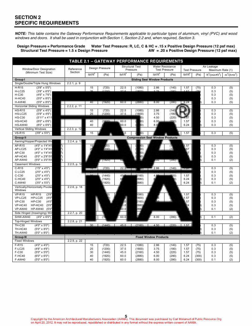
NOTE: This table contains the Gateway Performance Requirements applicable to particular types of aluminum, vinyl (PVC) and wood windows and doors. It shall be used in conjunction with Section 1, Section 2.2 and, when required, Section 3.
Design Pressure = Performance Grade Water Test Pressure: R, LC, C & HC = .15 x Positive Design Pressure (12 psf max) Structural Test Pressure = 1.5 x Design Pressure AW = .20 x Positive Design Pressure (12 psf max)
TABLE 2.1 – GATEWAY PERFORMANCE REQUIREMENTS Design Pressure Structural Test
Pressure Water Resistance
Test Pressure Air Leakage
Test Pressure Maximum Rate (1) Window/Door Designation (Minimum Test Size)
Reference Section
lbf/ft2 (Pa) lbf/ft2 (Pa) lbf/ft2 (Pa) lbf/ft2 (Pa) ft3/(min•f t2) m3/(h•m2)
Group I Sliding Seal Window Products Single/Double/Triple Hung Windows 2.2.1, p. 9 H-R15 (3'8" x 5'0") H-LC25 (3'8" x 6'5") H-C30 (4'6" x 7'6") H-HC40 (5'0" x 8'0") H-AW40 (5'0" x 8'0")
15 25 30 40 40
(720) (1200) (1440) (1920) (1920)
22.5 37.5 45.0 60.0 60.0
(1080) (1800) (2160) (2880) (2880)
2.86 3.75 4.50 6.00 8.00
(140) (180) (220) (290) (390)
1.57 1.57 1.57 1.57 6.24
(75) (75) (75) (75) (300)
0.3 0.3 0.3 0.3 0.3
(5) (5) (5) (5) (5)
Horizontal Sliding Windows 2.2.2, p. 11 HS-R15 (5'9" x 4'0") HS-LC25 (5'9" x 4'6") HS-C30 (5'11" x 4'11") HS-HC40 (8'0" x 6'6") HS-AW40 (8'0" x 6'6")
15 25 30 40 40
(720) (1200) (1440) (1920) (1920)
22.5 37.5 45.0 60.0 60.0
(1080) (1800) (2160) (2880) (2880)
2.86 3.75 4.50 6.00 8.00
(140) (180) (220) (290) (390)
1.57 1.57 1.57 1.57 6.24
(75) (75) (75) (75) (300)
0.3 0.3 0.3 0.3 0.3
(5) (5) (5) (5) (5)
Vertical Sliding Windows 2.2.3, p. 12 VS-R15 (3'8" x 5'0") 15 (720) 22.5 (1080) 2.86 (140) 1.57 (75) 0.3 (5)
Group II Compression Seal Window Products Awning/Hopper/Projected Windows 2.2.4, p. 13 AP-R15 (4'0" x 1'4"/4'0" x 1'4") AP-LC25 (4'0" x 1'4"/4'0" x 2'5") AP-C30 (4'0" x 1'4"/4'0" x 2'5") AP-HC40 (5'0" x 2'8"/5'0" x 2'8") AP-AW40 (5'0" x 3'0"/5'0" x 3'0")
15 25 30 40 40
(720) (1200) (1440) (1920) (1920)
22.5 37.5 45.0 60.0 60.0
(1080) (1800) (2160) (2880) (2880)
2.86 3.75 4.50 6.00 8.00
(140) (180) (220) (290) (390)
1.57 1.57 1.57 6.24 6.24
(75) (75) (75) (300) (300)
0.3 0.3 0.3 0.3 0.1
(5) (5) (5) (5) (2)
Casement Windows 2.2.5, p. 16 C-R15 (1'5" x 4'0") C-LC25 (2'0" x 4'0") C-C30 (2'0" x 4'0") C-HC40 (2'0" x 4'0") C-AW40 (3'0" x 5'0")
15 25 30 40 40
(720) (1200) (1440) (1920) (1920)
22.5 37.5 45.0 60.0 60.0
(1080) (1800) (2160) (2880) (2880)
2.86 3.75 4.50 6.00 8.00
(140) (180) (220) (290) (390)
1.57 1.57 1.57 6.24 6.24
(75) (75) (75) (300) (300)
0.3 0.3 0.3 0.3 0.1
(5) (5) (5) (5) (2)
Vertically/Horizontally Pivoted Windows
2.2.6, p. 18
VP-R15 HP-R15 (3'8" x 5'0") VP-LC25 HP-LC25 (4'0" x 5'0") VP-C30 HP-C30 (4'0" x 7'0") VP-HC40 HP-HC40 (5'0" x 8'0") VP-AW40 HP-AW40 (5'0" x 8'0")
15 25 30 40 40
(720) (1200) (1440) (1920) (1920)
22.5 37.5 45.0 60.0 60.0
(1080) (1800) (2160) (2880) (2880)
2.86 3.75 4.50 6.00 8.00
(140) (180) (220) (290) (390)
1.57 1.57 1.57 6.24 6.24
(75) (75) (75) (300) (300)
0.3 0.3 0.3 0.3 0.1
(5) (5) (5) (5) (2)
Side Hinged (Inswinging) Windows 2.2.7, p. 20 SHW-AW40 (4'0" x 6'0") 40 (1920) 60.0 (2880) 8.00 (390) 6.24 (300) 0.1 (2) Top-Hinged Windows 2.2.8, p. 21 TH-C30 (4'0" x 5'0") TH-HC40 (5'0" x 8'0") TH-AW40 (5'0" x 8'0")
30 40 40
(1440) (1920) (1920)
45.0 60.0 60.0
(2160) (2880) (2880)
4.50 6.00 8.00
(220) (290) (390)
1.57 6.24 6.24
(75) (300) (300)
0.3 0.3 0.1
(5) (5) (2)
Group III Fixed Window Products Fixed Windows 2.2.9, p. 22 F-R15 (4'0" x 4'0") F-LC25 (4'6" x 4'6") F-C30 (5'0" x 5'0") F-HC40 (6'0" x 6'0") F-AW40 (5'0" x 8'0")
15 25 30 40 40
(720) (1200) (1440) (1920) (1920)
22.5 37.5 45.0 60.0 60.0
(1080) (1800) (2160) (2880) (2880)
2.86 3.75 4.50 6.00 8.00
(140) (180) (220) (290) (390)
1.57 1.57 1.57 6.24 6.24
(75) (75) (75) (300) (300)
0.3 0.3 0.3 0.3 0.1
(5) (5) (5) (5) (2)
Copyright by the American Architectural Manufacturers Association (AAMA). This document was purchased by Carl Malamud of Public.Resource.Org on April 20, 2012. It may not be reproduced, republished or distributed in any format without the express written consent of AAMA.

6
Design Pressure Structural Test Pressure
Water Resistance Test Pressure
Air Leakage Test Pressure Maximum Rate (1) Window/Door Designation
(Minimum Test Size) Reference
Section lbf/ft2 (Pa) lbf/ft2 (Pa) lbf/ft2 (Pa) lbf/ft2 (Pa) ft3/(min•f t2) m3/(h•m2)
Group IV Dual Action Window Products Dual Action Windows 2.2.10, p. 23 DA-R15 (3'8" x 5'0") DA-LC25 (4'0" x 5'0") DA-C30 (4'0" x 6'0") DA-HC40 (5'0" x 8'0") DA-AW40 (5'0" x 8'0")
15 25 30 40 40
(720) (1200) (1440) (1920) (1920)
22.5 37.5 45.0 60.0 60.0
(1080) (1800) (2160) (2880) (2880)
2.86 3.75 4.50 6.00 8.00
(140) (180) (220) (290) (390)
1.57 1.57 1.57 6.24 6.24
(75) (75) (75) (300) (300)
0.3 0.3 0.3 0.3 0.1
(5) (5) (5) (5) (2)
Group V Specialty Window Products Basement Windows 2.2.11, p. 24 BW-R15 (2'8" x 1'4") BW-LC25 (2'8" x 1'4")
15 25
(720) (1200)
22.5 37.5
(1080) (1800)
2.86 3.75
(140) (180)
1.57 1.57
(75) (75)
0.3 0.3
(5) (5)
Hinged Egress Windows 2.2.12, p. 25 HE-R15 (Minimum size based
on window type) 15 (720) 22.5 (1080) 2.86 (140) 1.57 (75) 0.3 (5)(3)
Greenhouse Windows 2.2.13, p. 26 GH-R15 (3'0" x 3'0") 15 (720) 22.5 (1080) 2.86 (140) 1.57 (75) 0.3 (2) (5)(2) Jalousie Windows 2.2.14, p. 27 J-R15 (3'0" x 4'0") 15 (720) 22.5 (1080) 2.86 (140) 1.57 (75) 1.2 (22) Jal-Awning Windows 2.2.15, p. 27 JA-R15 (4'5" x 5'3") 15 (720) 22.5 (1080) 2.86 (140) 1.57 (75) 0.3 (2) (5)(2) Tropical Awning Windows 2.2.16, p. 28 TA-R15 (4'0" x 2'0"/4'0" x 5'3") TA-LC25 (4'5" x 2'2"/4'5" x 8'0") TA-C30 (4'5" x 2'2"/4'5" x 8'0")
15 25 30
(720) (1200) (1440)
22.5 37.5 45.0
(1080) (1800) (2160)
2.86 3.75 4.50
(140) (180) (220)
1.57 1.57 1.57
(75) (75) (75)
0.3 0.3 0.3
(5) (5) (5)
Group VI Door Products Hinged Glass Doors (4) 2.2.17, p. 28 HGD-R15 (2'8" x 6'6") HGD-LC25 (2'10"x 6'8") HGD-C30 (3'0" x 6'10") HGD-HC40 (4'8" x 8'0")
15 25 30 40
(720) (1200) (1440) (1920)
22.5 37.5 45.0 60.0
(1080) (1800) (2160) (2880)
2.86 3.75 4.50 6.00
(140) (180) (220) (290)
1.57 1.57 1.57 6.24
(75) (75) (75) (300)
0.3 0.3 0.3 0.3
(5) (5) (5) (5)
Dual Action Hinged Glass Doors (4) 2.2.18, p. 29 DA-HGD-R15 (2'8" x 6'6") DA-HGD-LC25 (2'10"x 6'8") DA-HGD-C30 (3'0" x 6'10") DA-HGD-HC40 (4'8" x 8'0")
15 25 30 40
(720) (1200) (1440) (1920)
22.5 37.5 45.0 60.0
(1080) (1800) (2160) (2880)
2.86 3.75 4.50 6.00
(140) (180) (220) (290)
1.57 1.57 1.57 6.24
(75) (75) (75) (300)
0.3 0.3 0.3 0.3
(5) (5) (5) (5)
Sliding Glass Doors (4) 2.2.19, p. 31 SGD-R15 (2'10"x 6'6") SGD-LC25 (3'6" x 6'8") SGD-C30 (3'10"x 6'10") SGD-HC40 (4'10"x 7'10") SGD-AW40 (4'10"x 7'10")
15 25 30 40 40
(720) (1200) (1440) (1920) (1920)
22.5 37.5 45.0 60.0 60.0
(1080) (1800) (2160) (2880) (2880)
2.86 3.75 4.50 6.00 8.00
(140) (180) (220) (290) (390)
1.57 1.57 1.57 6.24 6.24
(75) (75) (75) (300) (300)
0.3 0.3 0.3 0.3 0.3
(5) (5) (5) (5) (5)
(1) Products shall be rated for air leakage on a Pass/Fail basis. (2) Air leakage rate for Greenhouse and Jal-Awning Windows shall be measured as cubic feet per minute per square foot (cubic meter per hour per square meter) of finished window opening in the plane of the wall. (3) Air leakage for hinged perimeter frame window assemblies shall be rated on the basis of cfm/ft (cubic meter/hr/meter) of sash crack. On Hinged perimeter frame window assemblies, the perimeter crack between the stationary perimeter frame and the window frame plus the operable sash crack of the window itself shall be used in determining the sash crack. If the hinged perimeter frame window is a fixed window, only the perimeter crack between the stationary perimeter frame and the window frame shall be used. (4) Sizes for doors are given as panel width x frame height.
Copyright by the American Architectural Manufacturers Association (AAMA). This document was purchased by Carl Malamud of Public.Resource.Org on April 20, 2012. It may not be reproduced, republished or distributed in any format without the express written consent of AAMA.
7
2.1 TESTING REQUIREMENTS Table 2.1 indicates the Gateway Performance levels applicable to particular types of windows and doors. Section 2.2 indicates the specific product performance requirements. Section 3.0 indicates the material and component requirements. 2.1.1 TESTING SEQUENCE For conformance to this standard, the testing sequence shall be conducted as follows: operating force (when required), air leakage, resistance to water penetration, uniform structural deflection and uniform structural load tests. Concentrated Load, Forced Entry Resistance and Welded Corner tests are permitted to be performed on separate units or sash of identical size and design as used in the test unit. Specific product performance requirements shall be tested in the order specified in the appropriate paragraphs of Section 2.2. Operable units shall be fully opened and fully closed, a minimum of five times prior to testing. Within the sequence given above, additional tests required by code jurisdictions shall be permitted. 2.1.2 AIR LEAKAGE TEST With the unit closed and locked, it shall be subjected to an air leakage (per square foot of frame area) test in accordance with ASTM E 283. Dual windows shall be tested with the window in the winter mode. Air leakage shall not exceed the amount shown in Table 2.1. For purposes of this specification, products shall be rated for air leakage on a pass/fail basis. When determining the pass or fail status of a test specimen according to the performance levels stipulated in Table 2.1, the laboratory shall round off the measured air leakage to a single decimal place in accordance with the procedures outlined in ASTM E 29. The test report shall contain the statement: "The tested specimen meets (or exceeds) the performance levels specified in (specification reference) for air leakage;" or "The tested specimen fails to meet the performance levels specified in (specification reference) for air leakage," whichever is appropriate. NOTE: The laboratory shall be permitted to also report the measured air leakage to two decimal places in the test report at the request of the manufacturer.
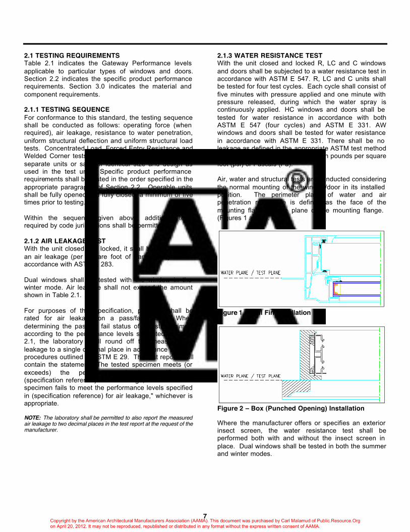
2.1.3 WATER RESISTANCE TEST With the unit closed and locked R, LC and C windows and doors shall be subjected to a water resistance test in accordance with ASTM E 547. R, LC and C units shall be tested for four test cycles. Each cycle shall consist of five minutes with pressure applied and one minute with pressure released, during which the water spray is continuously applied. HC windows and doors shall be tested for water resistance in accordance with both ASTM E 547 (four cycles) and ASTM E 331. AW windows and doors shall be tested for water resistance in accordance with ASTM E 331. There shall be no leakage as defined in the appropriate ASTM test method at the specified test pressure given in pounds per square foot (psf) or Pascals (Pa). Air, water and structural tests are conducted considering the normal mounting of the window/door in its installed position. The perimeter plane of water and air penetration resistance is defined as the face of the mounting flange or the plane of the mounting flange. (Figures 1 and 2).
Figure 1 – Nail Fin Installation
Figure 2 – Box (Punched Opening) Installation Where the manufacturer offers or specifies an exterior insect screen, the water resistance test shall be performed both with and without the insect screen in place. Dual windows shall be tested in both the summer and winter modes.
Copyright by the American Architectural Manufacturers Association (AAMA). This document was purchased by Carl Malamud of Public.Resource.Org on April 20, 2012. It may not be reproduced, republished or distributed in any format without the express written consent of AAMA.
8
2.1.4 UNIFORM LOAD TESTS 2.1.4.1 UNIFORM LOAD DEFLECTION TEST (For all AW Architectural Windows and HC Hung Windows only) The unit shall be subjected to a uniform load at the specified design pressure in Table 2.1 given in pounds per square foot (psf) applied both positively and negatively to the surface of the unit. No member shall deflect more than 1/175th of its span. Test shall be conducted in accordance with ASTM E 330. Dual windows shall be tested in both the summer and winter modes. 2.1.4.2 UNIFORM LOAD STRUCTURAL TEST A minimum uniform structural test pressure as specified (given in pounds per square foot) shall be applied to the unit, first the exterior pressure (positive) and then the interior pressure (negative). The sequence of applying the load is allowed to be reversed at the option of the laboratory. Each maximum pressure shall be stabilized and maintained for a period of 10 seconds. Tests shall be conducted in accordance with ASTM E 330. The unit shall be evaluated after each load. Dual windows shall be tested in both the summer and winter modes. For dual windows, testing of two separate units, one in the winter mode and one in the summer mode is permitted. Structural test pressures shown in Table 2.1 are for both positive and negative loads. After each specified loading, there shall be no glass breakage, permanent damage to fasteners, hardware parts, support arms or actuating mechanisms or any other damage which causes the window or door to be inoperable. There shall be no permanent deformation of any main frame, sash, panel or sash member in excess of 0.4% of its span for R, LC, C and HC class products or 0.2% of its span for AW class products. In dual windows, permanent deformation requirements apply to the primary window members only. 2.1.5 SAFETY DROP TEST (For vertically operating secondary window sash in dual windows only) The safety drop test is to be performed on those inserts that are normally operable for the purpose of ventilation. When the glazed sash is allowed to "free fall" the maximum distance provided by latch positions, it shall automatically stop in the next lower position on the first attempt and the glass shall be unbroken or, if broken, all pieces shall be retained in the insert.
2.1.6 CONCENTRATED LOAD GLASS ADHERENCE TEST (For secondary sash in dual windows only) A concentrated load equal to the weight of the sash but not less than 15 lbs (7 kg) acting parallel to the plane of the glass in the direction tending to pull the member off the glass and applied alternately for three minutes at the center of all surrounding members of a glazed sash shall not cause surrounding members to deflect more than 1/8 in (3.1 mm) each. 2.1.7 WELDED CORNER TEST (PVC products only) When main frame, sash or panel members are welded, all corners in the test unit shall be tested in accordance with the test method in Appendix A and meet the following requirements: 2.1.7.1 This test applies only when vinyl (PVC) is used as a primary structural member. 2.1.7.2 Weld seam shall be tested in the condition existing in the produced window or door product, except that all reinforcing shall be removed before performing the test. 2.1.7.3 When loaded to failure, the break shall not extend along the entire weld line. 2.1.8 FORCED-ENTRY RESISTANCE Locks shall provide reasonable security against forced entry. All windows shall be tested according to ASTM F 588 (Performance Level 10), AAMA 1302.5. Sliding glass doors shall be tested according to ASTM F 842 (Performance Grade 10), AAMA 1303.5. In dual windows, only the designated primary window shall be tested. NOTE: The performance requirements listed above may be exceeded by local code. In this event, the local code shall govern. Testing to higher performance levels is optional for purposes of this document. NOTE: FER testing of swing doors is not mandatory because there is no current ASTM test method for FER on swing doors. 2.1.9 CONDENSATION RESISTANCE (optional) When tested in accordance with AAMA 1503.1, the Condensation Resistance Factor (CRF) shall not be less than the value in the table below for the "CRF-Class" desired.
CRF Class Minimum Tested CRF C65 C60 C55 C50 C45 C40 C35
65 60 55 50 45 40 35
NOTE: See Appendix for detailed considerations concerning condensation resistance.
Copyright by the American Architectural Manufacturers Association (AAMA). This document was purchased by Carl Malamud of Public.Resource.Org on April 20, 2012. It may not be reproduced, republished or distributed in any format without the express written consent of AAMA.

9
2.1.10 THERMAL TRANSMITTANCE (optional) When thermal performance characteristics are to be determined, products shall be evaluated under the procedures in either AAMA 1503.1, ASTM E 1423 or NFRC 100. U-Values derived from differing test methods may vary slightly.
U-Value Class Maximum Tested "U"* U20 U25 U30 U35 U40 U45 U50 U55 U60 U65 U70
0.20 0.25 0.30 0.35 0.40 0.45 0.50 0.55 0.60 0.65 0.70
*"U" = BTU/h • ft2 • F NOTE: See Appendix for detailed considerations concerning thermal transmittance.
When U-Value is determined by these methods, the thermal transmittance (U) shall not exceed the values in the table above for the U-Value Class desired. U-Value Class shall be determined by the guidelines given in AAMA 1504. 2.1.11 ACOUSTICAL PERFORMANCE (optional) When acoustical performance characteristics are to be determined, all windows and doors shall be tested according to ASTM E 1425 or AAMA 1801.
Copyright by the American Architectural Manufacturers Association (AAMA). This document was purchased by Carl Malamud of Public.Resource.Org on April 20, 2012. It may not be reproduced, republished or distributed in any format without the express written consent of AAMA.

SINGLE, DOUBLE, AND TRIPLE HUNG WINDOWS
10
2.2 SPECIFIC PRODUCT PERFORMANCE REQUIREMENTS 2.2.1 SINGLE, DOUBLE, AND TRIPLE HUNG WINDOWS 2.2.1.1 Definition Hung windows are vertically operating windows in which the sash weight is offset by a counterbalancing mechanism mounted in the window. One or more locking devices are furnished to secure the sash in the closed position. Where single hung or triple hung windows are specified, they shall meet all provisions applying to double hung windows except that one sash or three sash, respectively shall be required to operate. 2.2.1.2 Designations and Performance Class Hung windows shall meet all the applicable requirements of Sections 1, 2.1, 3 and this Section for one of the following window designations:
Window Designation Class H-R15
H-DW-R15 H-LC25
H-DW-LC25 H-C30
H-DW-C30 H-HC40
H-DW-HC40 H-AW40
Residential Dual-Residential Light Commercial
Dual-Light Commercial Commercial
Dual Commercial Heavy Commercial
Dual-Heavy Commercial Architectural
2.2.1.3 Hardware 2.2.1.3.1 Primary window sash shall be equipped with counterbalancing mechanisms meeting AAMA 902. Corrosion resistance of hardware components shall comply with AAMA 907, where applicable. 2.2.1.3.2 Counter balancing mechanisms of appropriate size and capacity to hold the sash stationary at any open position shall be used for the weights of sash to be counterbalanced. Balances shall be serviceable in the field. 2.2.1.4 Construction - Dual Windows 2.2.1.4.1 Exterior secondary window sash shall not be operable or removable from the outside when closed. 2.2.1.4.2 Normally operated secondary window sash shall have hardware devices designed to hold sash secure and level in ventilating positions. Exterior storm sash (DW only) shall comply with AAMA 1002.10.
2.2.1.5 Test Sample Requirements Each specimen submitted for tests shall be a completely assembled and glazed window of standard construction in the largest size for which acceptance is sought under this standard but in no case less than the minimum size shown below:
Single, Double and Triple Hung Minimum Frame Size
Window Designation Width Height
H-R15 H-DW-R15
H-LC25 H-DW-LC25
H-C30 H-DW-C30
H-HC40 H-DW-HC40
H-AW40
3 ft 8 in (1120 mm) 3 ft 8 in (1120 mm) 3 ft 8 in (1120 mm) 3 ft 8 in (1120 mm) 4 ft 6 in (1370 mm) 4 ft 6 in (1370 mm) 5 ft 0 in (1520 mm) 5 ft 0 in (1520 mm) 5 ft 0 in (1520 mm)
5 ft 0 in (1520 mm) 5 ft 0 in (1520 mm) 6 ft 5 in (1960 mm) 6 ft 5 in (1960 mm) 7 ft 6 in (2290 mm) 7 ft 6 in (2290 mm) 8 ft 0 in (2440 mm) 8 ft 0 in (2440 mm) 8 ft 0 in (2440 mm)
NOTE: The diagrams shown above are typical but not all inclusive. Other configurations may be evaluated provided they follow the size guidelines listed below. Testing a B configuration will qualify windows produced in a D configuration.
Copyright by the American Architectural Manufacturers Association (AAMA). This document was purchased by Carl Malamud of Public.Resource.Org on April 20, 2012. It may not be reproduced, republished or distributed in any format without the express written consent of AAMA.
11
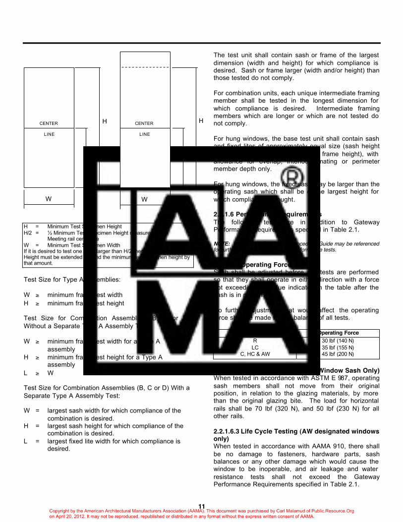
H = Minimum Test Specimen Height H/2 = ½ Minimum Test Specimen Height measured to Meeting rail centerline W = Minimum Test Specimen Width If it is desired to test one sash larger than H/2 then the Test Specimen Height must be extended beyond the minimum test specimen height by that amount. Test Size for Type A Assemblies: W ≥ minimum frame test width H ≥ minimum frame test height Test Size for Combination Assemblies (B, C or D) Without a Separate Type A Assembly Test: W ≥ minimum frame test width for a Type A
assembly H ≥ minimum frame test height for a Type A
assembly L ≥ W Test Size for Combination Assemblies (B, C or D) With a Separate Type A Assembly Test: W = largest sash width for which compliance of the
combination is desired. H = largest sash height for which compliance of the
combination is desired. L = largest fixed lite width for which compliance is
desired.
The test unit shall contain sash or frame of the largest dimension (width and height) for which compliance is desired. Sash or frame larger (width and/or height) than those tested do not comply. For combination units, each unique intermediate framing member shall be tested in the longest dimension for which compliance is desired. Intermediate framing members which are longer or which are not tested do not comply. For hung windows, the base test unit shall contain sash and fixed lites of approximately equal size (sash height is at least ½ of minimum gateway frame height), with allowance for overlap, interlock, mating or perimeter member depth only. For hung windows, the fixed sash may be larger than the operating sash which shall be of the largest height for which compliance is sought. 2.2.1.6 Performance Requirements The following tests are in addition to Gateway Performance Requirements specified in Table 2.1. NOTE: The AAMA Certification Procedural Guide may be referenced for further explanation of specific performance tests. 2.2.1.6.1 Operating Force Sash shall be adjusted before any tests are performed so that they shall operate in either direction with a force not exceeding the value indicated in the table after the sash is in motion. No further adjustment that would affect the operating force shall be made for the balance of all tests.
Window Designation Operating Force R LC
C, HC & AW
30 lbf (140 N) 35 lbf (155 N) 45 lbf (200 N)
2.2.1.6.2 Deglazing Test (Primary Window Sash Only) When tested in accordance with ASTM E 987, operating sash members shall not move from their original position, in relation to the glazing materials, by more than the original glazing bite. The load for horizontal rails shall be 70 lbf (320 N), and 50 lbf (230 N) for all other rails. 2.2.1.6.3 Life Cycle Testing (AW designated windows only) When tested in accordance with AAMA 910, there shall be no damage to fasteners, hardware parts, sash balances or any other damage which would cause the window to be inoperable, and air leakage and water resistance tests shall not exceed the Gateway Performance Requirements specified in Table 2.1.
H H
H/2 H/2
CENTER
LINE
CENTER
LINE
W W
Copyright by the American Architectural Manufacturers Association (AAMA). This document was purchased by Carl Malamud of Public.Resource.Org on April 20, 2012. It may not be reproduced, republished or distributed in any format without the express written consent of AAMA.

HORIZONTAL SLIDING WINDOWS
12
2.2.2 HORIZONTAL SLIDING WINDOWS 2.2.2.1 Definition Horizontal sliding windows consist of one or more horizontally operable sash in a sealing (or weathering) frame. When one sliding sash (X) and one fixed lite (O) make up the arrangement, the type is classified as a single slide (XO or OX). When two sash are separated by a fixed lite, the type is classified as a picture slide (XOX). When one sash is located at or near the center of the unit with a fixed lite at each end, the type is classified as a center slide (OXO). When two bi-parting sash are located at the center of the unit with fixed lites at each end, the type is classified is a bi-part center slide (OXXO). When two adjacent sash by-pass, the type is classified as a double slide, (such as XX or XXO). 2.2.2.2 Designations and Performance Class Horizontal sliding windows shall meet the applicable requirements of Section 1, 2.1, 3 and this Section for one of the following window designations:
Window Designation Class HS-R15
HS-DW-R15 HS-LC25
HS-DW-LC25 HS-C30
HS-DW-C30 HS-HC40
HS-DW-HC40 HS-AW40
Residential Dual-Residential Light Commercial
Dual-Light Commercial Commercial
Dual-Commercial Heavy Commercial
Dual-Heavy Commercial Architectural
2.2.2.3 Construction - Dual Windows 2.2.2.3.1 Exterior secondary window sash shall not be operable or removable from the outside when closed. 2.2.2.4 Test Sample Requirements Each specimen submitted for tests shall be a completely assembled and glazed window of standard construction in the largest size for which acceptance is sought under this standard but in no case less than the minimum size shown below:
Minimum Frame Size Window Designation Width Height
HS-R15 HS-DW-R15
HS-LC25 HS-DW-LC25
HS-C30 HS-DW-C30
HS-HC40 HS-DW-HC40
HS-AW40
5 ft 9 in (1753 mm) 5 ft 9 in (1753 mm) 5 ft 9 in (1753 mm) 5 ft 9 in (1753 mm) 5 ft 11 in (1803 mm) 5 ft 11 in (1803 mm) 8 ft 0 in (2440 mm) 8 ft 0 in (2440 mm) 8 ft 0 in (2440 mm)
4 ft 0 in (1220 mm) 4 ft 0 in (1220 mm) 4 ft 6 in (1372 mm) 4 ft 6 in (1372 mm) 4 ft 11 in (1499 mm) 4 ft 11 in (1499 mm) 6 ft 6 in (1980 mm) 6 ft 6 in (1980 mm) 6 ft 6 in (1980 mm)
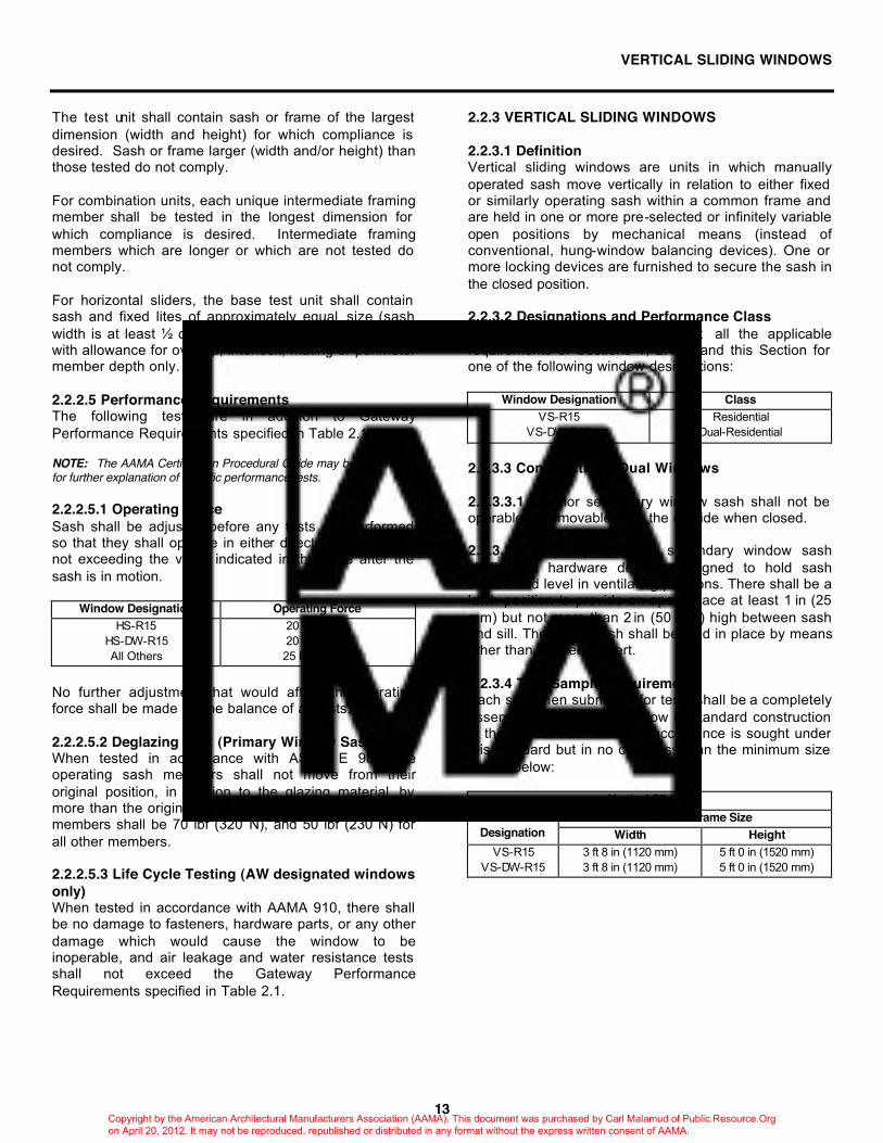
NOTE: The diagrams shown above are typical but not all inclusive. Other configurations may be evaluated provided they follow the size guidelines listed below. Test Size for Type A and B Assemblies: W ≥ minimum frame test width H ≥ minimum frame test height Test Size for Combination Assemblies (C, D or E) Without a Separate Type A Assembly Test: W ≥ minimum frame test width for a Type A
assembly H ≥ minimum frame test height for a Type A
assembly L ≥ S S = W/2 = 1/2 the minimum frame test width for a
Type A assembly Test Size for Combination Assemblies (C, D or E) With a Separate Type A Assembly Test: S = largest sash width for which compliance of the
combination is desired. H = largest sash height for which compliance of the
combination is desired. L = largest fixed lite width for which compliance is
desired.
Copyright by the American Architectural Manufacturers Association (AAMA). This document was purchased by Carl Malamud of Public.Resource.Org on April 20, 2012. It may not be reproduced, republished or distributed in any format without the express written consent of AAMA.
VERTICAL SLIDING WINDOWS
13
The test unit shall contain sash or frame of the largest dimension (width and height) for which compliance is desired. Sash or frame larger (width and/or height) than those tested do not comply. For combination units, each unique intermediate framing member shall be tested in the longest dimension for which compliance is desired. Intermediate framing members which are longer or which are not tested do not comply. For horizontal sliders, the base test unit shall contain sash and fixed lites of approximately equal size (sash width is at least ½ of the minimum gateway unit width), with allowance for overlap, interlock, mating or perimeter member depth only. 2.2.2.5 Performance Requirements The following tests are in addition to Gateway Performance Requirements specified in Table 2.1. NOTE: The AAMA Certification Procedural Guide may be referenced for further explanation of specific performance tests. 2.2.2.5.1 Operating Force Sash shall be adjusted before any tests are performed so that they shall operate in either direction with a force not exceeding the value indicated in the table after the sash is in motion.
Window Designation Operating Force HS-R15
HS-DW-R15 All Others
20 lbf (90 N) 20 lbf (90 N) 25 lbf (115 N)
No further adjustment that would affect the operating force shall be made for the balance of all tests. 2.2.2.5.2 Deglazing Test (Primary Window Sash Only) When tested in accordance with ASTM E 987, the operating sash members shall not move from their original position, in relation to the glazing material, by more than the original glazing bite. The load for vertical members shall be 70 lbf (320 N), and 50 lbf (230 N) for all other members. 2.2.2.5.3 Life Cycle Testing (AW designated windows only) When tested in accordance with AAMA 910, there shall be no damage to fasteners, hardware parts, or any other damage which would cause the window to be inoperable, and air leakage and water resistance tests shall not exceed the Gateway Performance Requirements specified in Table 2.1.
2.2.3 VERTICAL SLIDING WINDOWS 2.2.3.1 Definition Vertical sliding windows are units in which manually operated sash move vertically in relation to either fixed or similarly operating sash within a common frame and are held in one or more pre-selected or infinitely variable open positions by mechanical means (instead of conventional, hung-window balancing devices). One or more locking devices are furnished to secure the sash in the closed position. 2.2.3.2 Designations and Performance Class Vertical sliding windows shall meet all the applicable requirements of Sections 1, 2.1, 3 and this Section for one of the following window designations:
Window Designation Class VS-R15
VS-DW-R15 Residential
Dual-Residential
2.2.3.3 Construction - Dual Windows 2.2.3.3.1 Exterior secondary window sash shall not be operable or removable from the outside when closed. 2.2.3.3.2 Normally operated secondary window sash shall have hardware devices designed to hold sash secure and level in ventilating positions. There shall be a latch position to provide an open space at least 1 in (25 mm) but not more than 2 in (50 mm) high between sash and sill. The upper sash shall be held in place by means other than a screen insert. 2.2.3.4 Test Sample Requirements Each specimen submitted for tests shall be a completely assembled and glazed window of standard construction in the largest size for which acceptance is sought under this standard but in no case less than the minimum size shown below:
Vertical Sliding Minimum Frame Size Window
Designation Width Height VS-R15
VS-DW-R15 3 ft 8 in (1120 mm) 3 ft 8 in (1120 mm)
5 ft 0 in (1520 mm) 5 ft 0 in (1520 mm)
Copyright by the American Architectural Manufacturers Association (AAMA). This document was purchased by Carl Malamud of Public.Resource.Org on April 20, 2012. It may not be reproduced, republished or distributed in any format without the express written consent of AAMA.

AWNING, HOPPER, PROJECTED WINDOWS
14
2.2.3.5 Performance Requirements The following tests are in addition to Gateway Performance Requirements specified in Table 2.1. NOTE: The AAMA Certification Procedural Guide may be referenced for further explanation of specific performance tests. 2.2.3.5.1 Operating Force Sash shall be adjusted before any tests are performed so that they shall operate in either direction with a force not exceeding value indicated in the table after the sash is in motion.
Window Designation Operating Force VS-R15 and VS-DW-R15 35 lbf (155 N)
No further adjustment that would affect the operating force shall be made for the balance of all tests. 2.2.3.5.2 Deglazing Test (Primary Window Sash Only) When tested in accordance with ASTM E 987, the operating sash members shall not move from their original position, in relation to the glazing materials, by more than the original glazing bite. The load for horizontal members shall be 70 lbf (320 N) and 50 lbf (230 N) for all other members.
2.2.4 AWNING, HOPPER, PROJECTED WINDOWS 2.2.4.1 Definition Awning (POB), Hopper (PIT), and Projected windows have one or more sash hinged or pivoted at the top or bottom which project outward or inward from the plane of the window, with or without fixed lites of glass. An awning window rotates about its top edge and projects outward from the plane of the window at the bottom (POB). A hopper window pivots about its bottom edge and projects inward from the plane of the window at the top (PIT). 2.2.4.2 Designations and Performance Class Awning/Hopper/Projected windows shall meet all the applicable requirements of Sections 1, 2.1, 3 and this Section for one of the following window designations.
Window Designation Class AP-R15 AP-LC25 AP-C30 AP-HC40 AP-AW40
Residential Light Commercial
Commercial Heavy Commercial
Architectural
2.2.4.3 Hardware 2.2.4.3.1 Awning Windows The sash position shall be individually controlled within the frame. If used, roto operators shall comply with AAMA 901.1. If used, four-bar friction hinges shall comply with AAMA 904.1. Corrosion resistance of hardware components shall comply with AAMA 907, where applicable. 2.2.4.3.2 Hopper Windows The sash position shall be individually controlled within the frame. If used, four-bar friction hinges shall comply with AAMA 904.1. Corrosion resistance of hardware components shall comply with AAMA 907, where applicable. 2.2.4.3.3 Projected Windows Each sash shall be provided with two balance arms, with adjustable, non-abrasive friction pivots and/or friction shoes, or other hardware capable of supporting it in any open position or shall have four-bar friction hinges which comply with AAMA 904.1. Corrosion resistance of hardware components shall comply with AAMA 907, where applicable. 2.2.4.3.4 Reduction of the number of locks on units smaller than the tested specimen is permitted if substantiated by acceptable engineering calculations.
Copyright by the American Architectural Manufacturers Association (AAMA). This document was purchased by Carl Malamud of Public.Resource.Org on April 20, 2012. It may not be reproduced, republished or distributed in any format without the express written consent of AAMA.
15
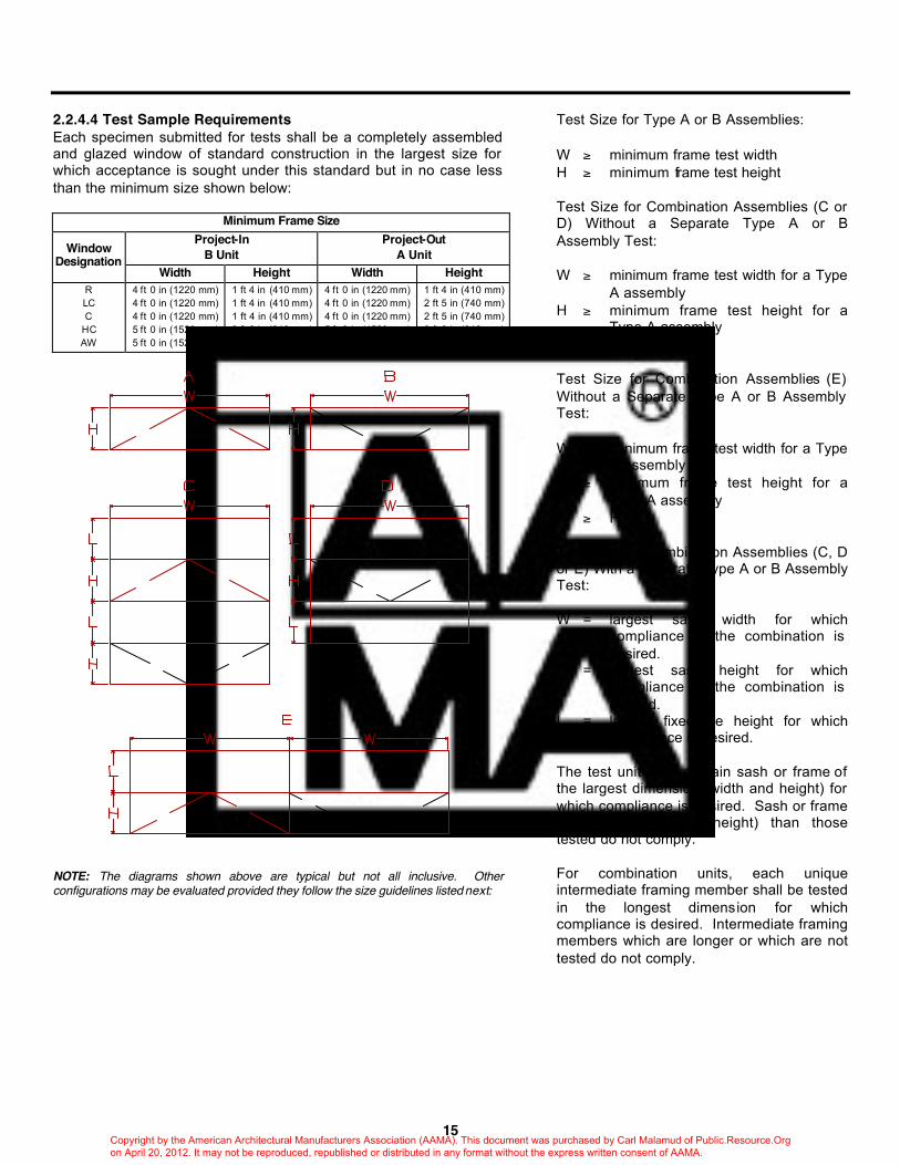
2.2.4.4 Test Sample Requirements Each specimen submitted for tests shall be a completely assembled and glazed window of standard construction in the largest size for which acceptance is sought under this standard but in no case less than the minimum size shown below:
Minimum Frame Size Project-In
B Unit Project-Out
A Unit Window Designation
Width Height Width Height R LC C
HC AW
4 ft 0 in (1220 mm) 4 ft 0 in (1220 mm) 4 ft 0 in (1220 mm) 5 ft 0 in (1520 mm) 5 ft 0 in (1520 mm)
1 ft 4 in (410 mm) 1 ft 4 in (410 mm) 1 ft 4 in (410 mm) 2 ft 8 in (810 mm) 3 ft 0 in (910 mm)
4 ft 0 in (1220 mm) 4 ft 0 in (1220 mm) 4 ft 0 in (1220 mm) 5 ft 0 in (1520 mm) 5 ft 0 in (1520 mm)
1 ft 4 in (410 mm) 2 ft 5 in (740 mm) 2 ft 5 in (740 mm) 2 ft 8 in (810 mm) 3 ft 0 in (910 mm)
NOTE: The diagrams shown above are typical but not all inclusive. Other configurations may be evaluated provided they follow the size guidelines listed next:
Test Size for Type A or B Assemblies: W ≥ minimum frame test width H ≥ minimum frame test height Test Size for Combination Assemblies (C or D) Without a Separate Type A or B Assembly Test: W ≥ minimum frame test width for a Type
A assembly H ≥ minimum frame test height for a
Type A assembly L ≥ H Test Size for Combination Assemblies (E) Without a Separate Type A or B Assembly Test: W ≥ minimum frame test width for a Type
A assembly H ≥ minimum frame test height for a
Type A assembly L ≥ H Test Size for Combination Assemblies (C, D or E) With a Separate Type A or B Assembly Test: W = largest sash width for which
compliance of the combination is desired.
H = largest sash height for which compliance of the combination is desired.
L = largest fixed lite height for which compliance is desired.
The test unit shall contain sash or frame of the largest dimension (width and height) for which compliance is desired. Sash or frame larger (width and/or height) than those tested do not comply. For combination units, each unique intermediate framing member shall be tested in the longest dimension for which compliance is desired. Intermediate framing members which are longer or which are not tested do not comply.
Copyright by the American Architectural Manufacturers Association (AAMA). This document was purchased by Carl Malamud of Public.Resource.Org on April 20, 2012. It may not be reproduced, republished or distributed in any format without the express written consent of AAMA.
16
2.2.4.5 Performance Requirements The following tests are in addition to Gateway Performance Requirements specified in Table 2.1. NOTE: The AAMA Certification Procedural Guide may be referenced for further explanation of specific performance tests. 2.2.4.5.1 Hardware Load Test (R and LC designated windows only) The test is performed on a glazed window with each sash open to 45° or to a maximum design opening, whichever is less, securely clamped and continuously supported around the outside perimeter. One free corner of each open sash shall be securely held in the open position by blocking between the corner of the sash and a fixed portion of window. A 17 lbf (80 N) concentrated load, acting from outside, perpendicular to the plane of a fixed portion and applied to the free rail of the sash at the point of the locking handle attachment, shall not cause a deflection at the free corner opposite the blocked corner, measured perpendicular to the plane of the fixed position, greater than 3.500 in (90 mm). There shall also be no glass breakage or damage to hardware and window parts that would make it inoperable. 2.2.4.5.2 Sash Torsion Tests (C designated windows only) With frame jambs rigidly supported in a vertical position, each glazed sash shall be opened to 45° or to a maximum design opening, whichever is less. All friction shall be removed from both jambs at sliding shoes, and each sash shall be free to move in its tracks. One side of each sash shall be blocked at the sliding shoe to prevent movement. A 30 lbf (135 N) concentrated load, applied vertically at the horizontal center of the hardware rail of each sash in the direction tending to force the sash toward a closed position, shall not cause a deflection in either direction at the free corner greater than indicated in the table, measured vertically to the nearest 0.01 inch at the corner of the opposite blocked sliding shoe:
Maximum Deflection (in) = 1.50 A/10.7 where: A = area of tested sash (ft2)
or Maximum Deflection (mm) = 38.1 B/.994
where B = area of tested sash (m2) Sash area shall be calculated using outside to outside dimensions. There shall be no glass breakage or damage to hardware and window parts that would make it inoperable. 2.2.4.5.3 Torsion Test (HC and AW designated windows only) The test is performed in both directions on an unglazed sash. The sash is supported on fulcrums at diagonally opposite corners with a third corner diagonally opposite the loaded corner secured in the same plane by a fulcrum support block and clamp. A 15 lbf (70 N) concentrated load, acting at the unrestrained corner of the sash shall not cause a deflection in either direction
measured to the nearest 0.01 inch at the unrestrained corner greater than indicated below:
Maximum Deflection (in) = 1.625 A/13.34 where: A = area of tested sash (ft2)
or Maximum Deflection (mm) = 41.3 B/1.24
where B = area of tested sash (m2) Sash area shall be calculated using outside to outside dimensions. Deflection shall be measured from the original position of the free corner after deflecting from its own weight. 2.2.4.5.4 Horizontal Concentrated Load Test on Latch Rail (Each sash) (HC and AW designated windows only) Support each unglazed sash by clamping the stiles, 6 in (155 mm) from the latch, to the horizontal supports under the jambs. A 30 lbf (135 N) concentrated load applied to the center of the span of the latch rail, perpendicular to the plane of the sash, first in one direction then in the opposite direction, shall not cause a deflection at the point of load application greater than 0.06 in (1.5 mm), measured to the nearest 0.01 inch. 2.2.4.5.5 Vertical Concentrated Load Test on Latch Rail (Each sash) (HC and AW designated windows only) Clamp the stiles of each unglazed sash to vertical supports 6 in (155 mm) from the latch rail. A 30 lbf (135 N) concentrated load applied at the center of the span of the latch rail, first in one direction then in the opposite direction, parallel to the plane of the sash, shall not cause a deflection at the point of load application greater than 0.06 in (1.5 mm), measured to the nearest 0.01 inch. 2.2.4.5.6 Torsion Load Test on Intermediate Frame Rails (HC and AW designated windows only) Place an unglazed window frame in a horizontal position. Apply a 40 in•lbfin (4.6 N•m) load [10 lbs (46 kg) on a 4 in (100 mm) lever arm measured from the extremity of the rail], at the center of the span of each intermediate horizontal rail, first in one direction, then in the opposite direction. Vertical deflection at point of load application shall be not greater than 0.07 in (1.7 mm), measured to the nearest 0.01 inch. 2.2.4.5.7 Vertical Concentrated Load Test on Intermediate Frame Rails (Over each sash) (HC and AW designated windows only) Clamp the jambs of the unglazed unit to vertical support 6 in (155 mm) from the test rails. A 30 lbf (135 N) concentrated load applied at the center of the span of any intermediate rail parallel to the plane of the window, first in one direction then in the opposite direction, shall not cause a deflection at the point of the load application greater than 0.06 in (1.5 mm), measured to the nearest 0.01 inch.
Copyright by the American Architectural Manufacturers Association (AAMA). This document was purchased by Carl Malamud of Public.Resource.Org on April 20, 2012. It may not be reproduced, republished or distributed in any format without the express written consent of AAMA.

CASEMENT WINDOWS
17
2.2.4.5.8 Balance Arm Load Test (HC designated windows only) If two or more sash are included in the test unit, compare the balance arm materials and cross sections, pivots, etc. If judged equal, test the largest sash only. Otherwise test all arms. Support the unglazed unit at 45° or to a maximum design opening, whichever is less, to the vertical and clamp the frame at its full height. Open the sash with the balance arms in compression, and block the sash in the level position at both friction shoes. Apply a 60 lbf (270 N) concentrated load vertically downward at one free corner of the sash for one minute. Then apply a 60 lbf (270 N) concentrated load vertically downward at the other free corner of sash for 1 minute. After removal of loads, the balance arms shall function normally with no apparent damage. 2.2.4.5.9 Life Cycle Testing (AW designated windows only) When tested in accordance with AAMA 910, there shall be no damage to fasteners, hardware parts, support arms, actuating mechanisms or any other damage which would cause the window to be inoperable, and air leakage and water resistance tests shall not exceed the Gateway Performance Requirements specified in Table 2.1.
2.2.5 CASEMENT WINDOWS 2.2.5.1 Definition Casement windows contain inswinging and/or outswinging sash that project away from the plane of the frame and are side hinged or pivoted at the jambs and swing about the vertical axis. Sash are mounted by use of hinging hardware which allow them to swing. The sash are usually operated by means of roto-operators or a handle. One or more locking handles are furnished to secure sash tightly in the frame in the closed position. They contain one or more sash, fixed lites and transoms in various combinations. 2.2.5.2 Designations and Performance Class Casement windows shall meet all the applicable requirements of Sections 1, 2.1, 3 and this Section for one of the following designations:
Window Designation Class C-R15 C-LC25 C-C30
C-HC40 C-AW40
Residential Light Commercial
Commercial Heavy Commercial
Architectural 2.2.5.3 Hardware 2.2.5.3.1 If used, four-bar friction hinges shall comply with AAMA 904.1. Corrosion resistance of hardware components shall comply with AAMA 907, where applicable. 2.2.5.3.2 Roto-type operators shall meet AAMA 901.1. Corrosion resistance of hardware components shall comply with AAMA 907, where applicable. 2.2.5.4 Projected Sash When used in combination with casement windows as covered in this section, projected sash shall meet the designated requirements for the following casement window designations:
Casement Window Designation
Projected Window Designation
C-R15 C-LC25 C-C30
C-HC40 C-AW40
AP-R15 AP-LC25 AP-C30
AP-HC40 AP-AW40
2.2.5.5 Test Sample Requirements Each specimen submitted for tests shall be a completely assembled and glazed window of standard construction in the largest size for which acceptance is sought under this standard but in no case less than the minimum size shown next:
Copyright by the American Architectural Manufacturers Association (AAMA). This document was purchased by Carl Malamud of Public.Resource.Org on April 20, 2012. It may not be reproduced, republished or distributed in any format without the express written consent of AAMA.

18
Minimum Frame Size Window Designation Width Height
C-R15 C-LC25 C-C30
C-HC40 C-AW40
1 ft 5 in (430 mm) 2 ft 0 in (610 mm) 2 ft 0 in (610 mm) 2 ft 0 in (610 mm) 3 ft 0 in (910 mm)
4 ft 0 in (1220 mm) 4 ft 0 in (1220 mm) 4 ft 0 in (1220 mm) 4 ft 0 in (1220 mm) 5 ft 0 in (1520 mm)
NOTE: The diagrams shown above are typical but not all inclusive. Other configurations may be evaluated provided they follow the size guidelines listed below. Test Size for Type A Assemblies: W ≥ minimum frame test width H ≥ minimum frame test height Test Size for Combination Assemblies (B, C or D) Without a Separate Type A Assembly Test: W ≥ minimum frame test width for a Type A
assembly H ≥ minimum frame test height for a Type A
assembly L ≥ W Test Size for Combination Assemblies (B, C or D) With a Separate Type A Assembly Test: W = largest sash width for which compliance of the
combination is desired. H = largest sash height for which compliance of the
combination is desired. L = largest fixed lite width for which compliance is
desired.
The test unit shall contain sash or frame of the largest dimension (width and height) for which compliance is desired. Sash or frame larger (width and/or height) than those tested do not comply. For combination units, each unique intermediate framing member shall be tested in the longest dimension for which compliance is desired. Intermediate framing members which are longer or which are not tested do not comply. 2.2.5.6 Performance Requirements The following tests are in addition to Gateway Performance Requirements specified in Table 2.1. NOTE: The AAMA Certification Procedural Guide may be referenced for further explanation of specific performance tests. 2.2.5.6.1 Vertical Deflection Test On a completely assembled and glazed window, with manufacturer's standard hardware, a concentrated load as indicated in the table and acting at the lower unrestricted corner of a sash opened 90° or maximum design opening, shall not cause a vertical deflection at the lower unrestrained corner greater than 0.25 in/ft (20 mm/m) of sash width measured to the nearest 0.01 inch. At the conclusion of the test the sash shall properly close and operate.
Window Designation Concentrated Load C-R15 C-LC25 C-C30
C-HC40 C-AW40
45 lbf (200 N) 45 lbf (200 N) 60 lbf (270 N) 60 lbf (270 N) 60 lbf (270 N)
2.2.5.6.2 Hardware Load Test For windows containing sash with roto-operating hardware, the window shall be securely fastened in a vertical plane so that sash, when opened to their full extent, will be horizontal. Sash shall be strong enough to support a uniform load indicated in the table. At the conclusion of the test, the operators shall fully close the sash. There shall be no failure of screws or track or permanent deformation of support arms. The sash shall be tested with the load applied in one direction, then in the opposite direction.
Window Designation Load C-R15 C-LC25 C-C30
C-HC40 C-AW40
5.00 lbf/ft2 (240 Pa)* 6.24 lbf/ft2 (300 Pa)* 6.24 lbf/ft2 (300 Pa)* 6.24 lbf/ft2 (300 Pa)* 6.24 lbf/ft2 (300 Pa)*
*The load specified includes the weight of the glazed sash.
Copyright by the American Architectural Manufacturers Association (AAMA). This document was purchased by Carl Malamud of Public.Resource.Org on April 20, 2012. It may not be reproduced, republished or distributed in any format without the express written consent of AAMA.
VERTICALLY OR HORIZONTALLY PIVOTED WINDOWS
19
2.2.5.6.3 Torsion Test (HC and AW designated windows only) The test is performed in both directions on an unglazed sash. The sash is supported on fulcrums at diagonally opposite corners, with a third corner diagonally opposite the loaded corner secured in the same plane by fulcrum support block and clamp. A 20 lbf (90 N) concentrated load, acting at an unrestrained corner of the sash shall not cause a deflection in either direction measured to the nearest 0.01 inch at the unrestrained corner greater than indicated in the table.
Maximum Deflection (in) = 1.50 A /8 Where A = area of tested sash (ft2)
or Maximum Deflection (mm) = 38.1 B/.744
Where B = area of tested sash (m2) Sash area shall be calculated using outside to outside dimensions. Deflection shall be measured from original position of free corner after deflecting from its own weight. 2.2.5.6.4 Life Cycle Testing (AW designated windows only) When tested in accordance with AAMA 910, there shall be no damage to fasteners, hardware parts, support arms, actuating mechanisms or any other damage which would cause the window to be inoperable, and air leakage and water resistance tests shall not exceed the primary performance requirements specified in Table 2.1.
2.2.6 VERTICALLY OR HORIZONTALLY PIVOTED WINDOWS 2.2.6.1 Definition Vertically or horizontally pivoted windows consist of a sash pivoted either at head and sill or at the jambs in the center of the main frame which reverses or rotates a full 360° around its vertical or horizontal axis. When rotated 180°, where it is held for the purpose of cleaning the outside surfaces, it also provides a weather seal. Upon completion of the cleaning operation, the sash is rotated another 180° to the normal, closed position where it is again locked. 2.2.6.2 Designation and Performance Class Vertically and horizontally pivoted windows shall meet all the applicable requirements of Sections 1, 2.1, 3 and this Section for one of the following designations:
Window Designation Class VP-R15 HP-R15 VP-LC25 HP-LC25 VP-C30 HP-C30
VP-HC40 HP-HC40 VP-AW40 HP-AW40
Residential Light Commercial
Commercial Heavy Commercial
Architectural 2.2.6.3 Projected Sash When used in combination with vertically or horizontally pivoted windows as covered in this section, projected sash shall meet the designated requirements for the following pivoted window designations:
Vertically Pivoted Window Designation
Projected Window Designation
VP-R15 HP-R15 VP-LC25 HP-LC25 VP-C30 HP-C30
VP-HC40 HP-HC40 VP-AW40 HP-AW40
AP-R15 AP-LC25 AP-C30
AP-HC40 AP-AW40
2.2.6.4 Test Sample Requirements Each specimen submitted for tests shall be a completely assembled and glazed window of standard construction in the largest size for which acceptance is sought under this standard but in no case less than the minimum size shown below:
Minimum Frame Size Window Designation Width Height
VP-R15 HP-R15 VP-LC25 HP-LC25 VP-C30 HP-C30
VP-HC40 HP-HC40 VP-AW40 HP-AW40
3 ft 8 in (1120 mm) 4 ft 0 in (1220 mm) 4 ft 0 in (1220 mm) 5 ft 0 in (1520 mm) 5 ft 0 in (1520 mm)
5 ft 0 in (1520 mm) 5 ft 0 in (1520 mm) 7 ft 0 in (2130 mm) 8 ft 0 in (2440 mm) 8 ft 0 in (2440 mm)
Copyright by the American Architectural Manufacturers Association (AAMA). This document was purchased by Carl Malamud of Public.Resource.Org on April 20, 2012. It may not be reproduced, republished or distributed in any format without the express written consent of AAMA.
20
Manufacturers desiring to produce windows which include a project-in sash under the cleaning sash shall furnish a test window to include their largest standard size project-in sash, increasing the height of the test window as necessary to avoid reducing the height of the pivoted sash. 2.2.6.5 Performance Requirements The following tests are in addition to Gateway Performance Requirements specified in Table 2.1. NOTE: The AAMA Certification Procedural Guide may be referenced for further explanation of specific performance tests. 2.2.6.5.1 Torsion Test (C, HC and AW designated windows only) The test is performed in both directions on an unglazed cleaning sash. The sash is supported on fulcrums at diagonally opposite corners, with a third corner diagonally opposite the loaded corner secured in the same plane by a fulcrum support block and clamp. A 15 lbf (70 N) concentrated load, acting at the unrestrained corner of the sash shall not cause a deflection in either direction measured to the nearest 0.01 inch at the unrestrained corner greater than indicated in below:
Window Designation Maximum Deflection (in) VP-C30 HP-C30
VP-HC40 HP-HC40 VP-AW40 HP-AW40
2.00 A/18.5 2.50 A/37.8 2.50 A/37.8
Where A = area of tested sash (ft2) Window Designation Maximum Deflection (mm) VP-C30 HP-C30
VP-HC40 HP-HC40 VP-AW40 HP-AW40
50.8 B/1.72 63.5 B/3.51 63.5 B/3.51
Where B = area of tested sash (m2) Deflection shall be measured from the original position of the free corner after deflecting from its own weight. 2.2.6.5.2 Horizontal Concentrated Load Test (C, HC and AW designated windows only) Support the unglazed pivoted sash by clamping the stiles, 6 in (155 mm) from the bottom rail, to the horizontal or vertical supports under the jambs or head and sill respectively. A concentrated load as indicated in the table, shall be applied at the center of the span of the lower rail, perpendicular to the plane of the sash, first in one direction then in the opposite direction. Deflection at the point of load application shall not exceed 0.06 in (1.5 mm), measured to the nearest 0.01 inch.
Window Designation Concentrated Load VP-C30 HP-C30
VP-HC40 HP-HC40 VP-AW40 HP-AW40
50 lbf (230 N) 60 lbf (270 N) 60 lbf (270 N)
2.2.6.5.3 Vertical Concentrated Load Test (C, HC and AW designated windows only) This test is performed with the unglazed pivoted sash in the frame using the pivots as the sole support with the sash in the 90° open position. Two concentrated loads, as indicated in the table, one each at mid-points between the pivot and the innermost extremity of the sash stiles or rails, shall be applied to the lower rail or stile, parallel to the plane of the sash. Deflections at either free corner of the sash lower rail or stile shall not exceed 0.03 in (0.8 mm), measured to the nearest 0.01 inch.
Window Designation Concentrated Load (each) VP-C30 HP-C30
VP-HC40 HP-HC40 VP-AW40 HP-AW40
50 lbf (230 N) 60 lbf (270 N) 60 lbf (270 N)
2.2.6.5.4 Life Cycle Testing (AW designated windows only) When tested in accordance with AAMA 910, there shall be no damage to fasteners, hardware parts, support arms, actuating mechanisms or any other damage which would cause the window to be inoperable, and air leakage and water resistance tests shall not exceed the gateway performance requirements specified in Table 2.1.
Copyright by the American Architectural Manufacturers Association (AAMA). This document was purchased by Carl Malamud of Public.Resource.Org on April 20, 2012. It may not be reproduced, republished or distributed in any format without the express written consent of AAMA.
SIDE-HINGED (INSWINGING) WINDOWS
21
2.2.7 SIDE-HINGED (INSWINGING) WINDOWS 2.2.7.1 Definition Side-Hinged (Inswinging) Windows contain sash that project inward from the plane of the frame and are hinged at the jamb to swing about a vertical axis. Sash are mounted to the frame with exposed or concealed butt (close-up) hinges or four bar hinges on smaller vents. They contain one or more sash with or without fixed lites and transoms in various combinations. Side-Hinged (Inswinging) windows are used for cleaning access or emergency ventilation. 2.2.7.2 Designations and Performance Class Side-Hinged (Inswinging) windows shall meet all applicable requirements of Sections 1, 2.1, 3 and this Section for the following designation:
Window Designation Class SHW-AW40 Architectural
2.2.7.3 Hardware 2.2.7.3.1 Sash shall have at least one keyed limit device which prohibits the sash from freely swinging inward. 2.2.7.3.2 Hinges shall be applied near corners of sash, with an additional center hinge provided where units are over 4 ft 0 in (1220 mm). 2.2.7.3.3 If used, four-bar friction hinges, shall comply with AAMA 904.1. Use of four-bar hinges shall be limited to sash sizes not exceeding hardware manufacturer's weight restrictions. Corrosion resistance of hardware components shall comply with AAMA 907, where applicable. 2.2.7.4 Test Sample Requirements Specimen(s) submitted for tests shall be a completely assembled and glazed window of standard construction in the largest size for which acceptance is sought under this standard but in no case less than the minimum size shown below:
Minimum Frame Size Window Designation Width Height SHW-AW40 4 ft 0 in (1220 mm) 6 ft 0 in (1830 mm)
2.2.7.5 Performance Requirements The following tests are in addition to Gateway Performance Requirements specified in Table 2.1. NOTE: The AAMA Certification Procedural Guide may be referenced for further explanation of specific performance tests. 2.2.7.5.1 Life Cycle Testing (AW designated windows only) When tested in accordance with AAMA 910, there shall be no damage to fasteners, hardware parts, support arms, actuating mechanisms or any other damage which would cause the window to be inoperable, and air leakage and water resistance tests shall not exceed the Gateway Performance Requirements specified in Table 2.1.
Copyright by the American Architectural Manufacturers Association (AAMA). This document was purchased by Carl Malamud of Public.Resource.Org on April 20, 2012. It may not be reproduced, republished or distributed in any format without the express written consent of AAMA.

TOP-HINGED WINDOWS
22
2.2.8 TOP-HINGED WINDOWS 2.2.8.1 Definition A top-hinged window consists of a sash hinged to the main frame at the head so that it swings open to the inside (inswinging) or swings open to the outside (outswinging). Windows of this type are normally kept closed and locked or the opening dimension is limited. Top-hinged inswinging windows are designed to operate primarily for cleaning, not to provide ventilation. Top-hinged outswinging windows are designed to operate primarily for ventilation, limited access or emergency egress. A variation of the top-hinged window is called a drop-head and is essentially the same except that it is hung on two four-bar friction hinges, mounted in the jambs at the top. 2.2.8.2 Designations and Performance Class Top-hinged windows shall meet all the applicable requirements of Sections 1, 2.1, 3 and this Section for one of the following window designations:
Window Designation Class TH-C30
TH-HC40 TH-AW40
Commercial Heavy Commercial
Architectural 2.2.8.3 Construction 2.2.8.3.1 Hinges, if integrally extruded, shall be continuous. If not integrally extruded, they shall be applied either as continuous or individual hinges. Individual hinges shall be applied at outermost corners of the sash with an additional center hinge provided where windows are over 4 ft 0 in (1220 mm) wide for C designated windows and 5 ft 0 in (1520 mm) wide for HC and AW designated windows. 2.2.8.3.2 Sash shall have at least two hold-open arms attached to the frame and sash or removable stay bar securely attached when the sash is opened. When the sash is in the open position, hold-open arms or stay bar shall provide positive positioning of the sash. 2.2.8.3 Test Sample Requirements Each specimen submitted for tests shall be a completely assembled and glazed window of standard construction and of at least the size given below:
Minimum Frame Size Window Designation Width Height
TH-C30 TH-HC40 TH-AW40
4 ft 0 in (1220 mm) 5 ft 0 in (1520 mm) 5 ft 0 in (1520 mm)
5 ft 0 in (1520 mm) 8 ft 0 in (2440 mm) 8 ft 0 in (2440 mm)
2.2.8.4 Performance Requirements The following tests are in addition to Gateway Performance Requirements specified in Table 2.1. NOTE: The AAMA Certification Procedural Guide may be referenced for further explanation of specific performance tests. 2.2.8.4.1 Hold Open Arm or Stay Bar Load Test (C and HC designated windows only) With the glazed sash opened to its fullest extent, a 100 lbf (450 N) horizontal concentrated load shall be applied at one lower corner of the sash in the closing direction. After removal of the load, hold-open arms shall function normally with no apparent damage. 2.2.8.4.2 Torsion Test The test is performed in both directions on an unglazed sash. The sash is supported on fulcrums at diagonally opposite corners, with a third corner diagonally opposite the loaded corner secured in the same plane by a fulcrum support block and clamp. A 15 lbf (70 N) concentrated load, acting at an unrestrained corner of the sash shall not cause a deflection in either direction at an unrestrained corner greater than indicated in the table:
Window Designation Maximum Deflection (in) TH-C30
TH-HC40 TH-AW40
4.00 A/18.5 8.00 A/37.8 8.00 A/37.8
Where A = area of tested sash (ft2) Window Designation Maximum Deflection (mm)
TH-C30 TH-HC40 TH-AW40
102 B/1.72 203 B/3.51 203 B/3.51
Where B = area of tested sash (m2) Deflection shall be measured to the nearest 0.01 inch from the original position of the free corner after deflecting from its own weight. 2.2.8.4.3 Horizontal Concentrated Load Test Support the unglazed sash by clamping the stiles, 6 in (155 mm) from the bottom rail, to horizontal supports under the jambs. A 30 lbf (135 N) concentrated load shall be applied at the center of the span of the bottom rail, perpendicular to the plane of the sash, first in one direction then in the opposite direction. Deflection at the point of load application shall not exceed 0.06 in (1.5 mm), measured to the nearest 0.01 inch.
Copyright by the American Architectural Manufacturers Association (AAMA). This document was purchased by Carl Malamud of Public.Resource.Org on April 20, 2012. It may not be reproduced, republished or distributed in any format without the express written consent of AAMA.
FIXED WINDOWS
23
2.2.8.4.4 Vertical Concentrated Load Test Support the unglazed sash by clamping the stiles to vertical supports. A concentrated load as indicated in the table, shall be applied at the center of the span of the bottom rail, parallel to the plane of the sash, first in one direction then in the opposite direction. Deflection measured to the nearest 0.01 inch at the point of load application shall not exceed the value indicated in the table.
Window Designation
Concentrated Load
Maximum Deflection
TH-C30 TH-HC40 TH-AW40
50 lbf (230 N) 90 lbf (400 N) 90 lbf (400 N)
0.13 in (3.3 mm) 0.25 in (6.3 mm) 0.25 in (6.3 mm)
2.2.8.4.5 Life Cycle Testing (AW designated windows only) When tested in accordance with AAMA 910, there shall be no damage to fasteners, hardware parts, support arms, actuating mechanisms or any other damage which would cause the window to be inoperable, and air leakage and water resistance tests shall not exceed the Gateway Performance Requirements specified in Table 2.1.
2.2.9 FIXED WINDOWS 2.2.9.1 Definition Fixed windows consist of a glazed frame or a fixed sash and frame installed into the opening and are not operable. Provisions are made so they can be reglazed or replaced in the field. 2.2.9.2 Designations and Performance Class Fixed windows shall meet all the applicable requirements of Sections 1, 2.1, 3 and this Section for one of the following window designations:
Window Designation Class F-R15
F-DW-R15 F-LC25
F-DW-LC25 F-C30
F-DW-C30 F-HC40
F-DW-HC40 F-AW40
Residential Dual-Residential Light Commercial
Dual-Light Commercial Commercial
Dual-Commercial Heavy Commercial
Dual-Heavy Commercial Architectural
2.2.9.3 Test Sample Requirements Each specimen submitted for tests shall be a completely assembled and glazed window of standard construction in the largest size for which acceptance is sought under this standard but in no case less than the minimum size shown below:
Minimum Frame Size Window Designation Width Height
F-R15 F-DW-R15
F-LC25 F-DW-LC25
F-C30 F-DW-C30
F-HC40 F-DW-HC40
F-AW40
4 ft 0 in (1220 mm) 4 ft 0 in (1220 mm) 4 ft 6 in (1372 mm) 4 ft 6 in (1372 mm) 5 ft 0 in (1520 mm) 5 ft 0 in (1520 mm) 6 ft 0 in (1830 mm) 6 ft 0 in (1830 mm) 5 ft 0 in (1520 mm)
4 ft 0 in" (1220 mm) 4 ft 0 in (1220 mm) 4 ft 6 in (1372 mm) 4 ft 6 in (1372 mm) 5 ft 0 in (1520 mm) 5 ft 0 in (1520 mm) 6 ft 0 in (1830 mm) 6 ft 0 in (1830 mm) 8 ft 0 in (2240 mm)
NOTE: Fixed windows by definition do not contain operating sash, therefore, the AW class is not required to undergo life cycle testing.
Copyright by the American Architectural Manufacturers Association (AAMA). This document was purchased by Carl Malamud of Public.Resource.Org on April 20, 2012. It may not be reproduced, republished or distributed in any format without the express written consent of AAMA.
DUAL ACTION WINDOWS
24
2.2.10 DUAL ACTION WINDOWS 2.2.10.1 Definition Dual action windows consist of a sash that tilts into the room from the top for ventilation and swings in from the side for cleaning of the outside surface. When swung from the side the sash shall swing in sufficiently to allow safe access to the outside surface. 2.2.10.2 Designation and Performance Class Dual Action Windows shall meet all the applicable requirements of Sections 1, 2.1, 3 and this Section for one of the following window designations:
Window Designation Class DA-R15 DA-LC25 DA-C30
DA-HC40 DA-AW40
Residential Light Commercial
Commercial Heavy Commercial
Architectural
2.2.10.3 Construction 2.2.10.3.1 Sash shall have one or more stabilizing arms attached to the frame when the sash is opened from the top. When the sash is in the tilt-open position, stabilizing arms shall provide positive positioning of the sash. 2.2.10.4 Hardware Each sash shall be equipped with one handle to provide both "tilt" and "swing" operation. The "swing" or "tilt" position shall be individually selected and rendered operable starting only from the closed sash position. A secondary locking device to prevent accidental "swing" operation is allowed for each sash. 2.2.10.5 Test Sample Requirements Each specimen submitted for tests shall be a completely assembled and glazed window of standard construction and of at least the size given below:
Minimum Frame Size Window Designation Width Height
DA-R15 DA-LC25 DA-C30
DA-HC40 DA-AW40
3 ft 8 in (1120 mm) 4 ft 0 in (1220 mm) 4 ft 0 in (1220 mm) 5 ft 0 in (1520 mm) 5 ft 0 in (1520 mm)
5 ft 0 in (1520 mm) 5 ft 0 in (1520 mm) 6 ft 0 in (1830 mm) 8 ft 0 in (2440 mm) 8 ft 0 in (2440 mm)
Access sash, when furnished, shall be closed and locked for all tests.
2.2.10.6 Performance Requirements The following tests are in addition to Gateway Performance Requirements specified in Table 2.1. NOTE: The AAMA Certification Procedural Guide may be referenced for further explanation of specific performance tests. 2.2.10.6.1 Torsion Test (HC and AW designated windows only) The test is performed in both directions on an unglazed sash. The sash is supported on fulcrums at diagonally opposite corners, with a third corner diagonally opposite the loaded corner secured in the same plane by a fulcrum support block and clamp. A 15 lbf (70 N) concentrated load, acting at the unrestrained corner of the sash, shall not cause a deflection in either direction measured to the nearest 0.01 inch at the unrestrained corner greater than indicated in the table.
Maximum Deflection (in) = 8.00 A/37.8 where: A = area of tested sash (ft2)
or Maximum Deflection (mm) = 203 B/3.51
where B = area of tested sash (m2) Sash area shall be calculated using outside to outside dimensions. Deflection shall be measured from the original position of the free corner after the deflection from its own weight.
2.2.10.6.2 Horizontal Concentrated Load Test Support the unglazed sash by clamping the stiles, 6 in (155 mm) from the top rail to the horizontal supports under the jambs. A 30 lbf (135 N) concentrated load shall be applied at the center of the span of the top rail, perpendicular to the plane of the sash. The concentrated load shall be applied first in one direction and then in the opposite direction. Deflection at the point of the load application shall not exceed 0.06 in (1.5 mm), measured to the nearest 0.01 inch. 2.2.10.6.3 Vertical Concentrated Load Test (R, LC, C and HC designated windows only) Support the unglazed sash by clamping the stiles to the vertical supports. A concentrated load acting downward as indicated in the table, shall be applied at the center of the span of the bottom rail, parallel to the plane of the sash. Deflection at the point of the load application shall not exceed the value indicated in the table.
Window Designation
Concentrated Load
Maximum Deflection
DA-R15 DA-LC25 DA-C30
DA-HC40
30 lbf (135 N) 40 lbf (180 N) 50 lbf (230 N) 90 lbf (400 N)
0.06 in (1.5 mm) 0.09 in (2.3 mm) 0.13 in (3.3 mm) 0.25 in (6.4 mm)
Copyright by the American Architectural Manufacturers Association (AAMA). This document was purchased by Carl Malamud of Public.Resource.Org on April 20, 2012. It may not be reproduced, republished or distributed in any format without the express written consent of AAMA.

BASEMENT WINDOWS
25
2.2.10.6.4 Stabilizing Arm Load: Concentrated Load on Sash Corners (R, LC, C and HC designated windows only) Mount the completely assembled glazed window vertically. Open the sash inward from the top, to the full venting position with the sash supported solely by the stabilizing arm at one jamb. A concentrated load acting vertically downward as indicated in the table, shall be applied at each upper sash corner separately. After load removal, there shall be no damage to the window frame, sash, window components, glass, stabilizing arm or hardware components, and the window shall function normally.
Window Designation Concentrated Load DA-R15 DA-LC25 DA-C30
DA-HC40
100 lbf (445 N) 200 lbf (890 N) 200 lbf (890 N) 200 lbf (890 N)
2.2.10.6.5 Stabilizing Arm Load: Concentrated Load on Sash Top Rail (R, LC, C and HC designated windows only) Mount the completely assembled glazed window vertically. Open the sash inward from the top to the full ventilating position with the sash supported solely by stabilizing arm at one jamb. A concentrated load acting vertically downward as indicated in the table, shall be applied to the center of the top sash rail. After the load removal, there shall be no damage to the window frame, sash, window components, glass, stabilizing arm or hardware components, and the window shall function normally.
Window Designation Concentrated Load DA-R15 DA-LC25 DA-C30
DA-HC40
200 lbf (890 N) 400 lbf (1780 N) 400 lbf (1780 N) 400 lbf (1780 N)
2.2.10.6.6 Life Cycle Testing (AW designated windows only) When tested in accordance with AAMA 910, there shall be no damage to fasteners, hardware parts, support arms, actuating mechanisms or any other damage which would cause the window to be inoperable, and air infiltration and water resistance tests shall not exceed the Gateway Performance Requirements specified in Table 2.1.
2.2.11 BASEMENT WINDOWS 2.2.11.1 Definition A sash unit, usually of the inswinging awning or hopper type, used for basement or cellar sash openings. Any operating type may be tested as a basement window provided they are intended to be installed at or below grade for the purposes of ventilating a basement or cellar area. Products may include screens or storm sash and may include provisions for emergency egress from the basement area. 2.2.11.2 Designation and Performance Class Basement windows shall meet all of the applicable requirements of Sections 1, 2.1, 3 and this Section for one of the following window designations:
Window Designation Class BW-R15 BW-LC25
Residential Light Commercial
2.2.11.3 Hardware 2.2.11.3.1 Basement Awning Windows (POB) The sash position shall be individually controlled within the frame. If used, four-bar friction hinges shall comply with AAMA 904.1. Corrosion resistance of hardware components shall comply with AAMA 907, where applicable. 2.2.11.3.2 Basement Hopper Windows (PIT) The sash position shall be individually controlled within the frame. If used, four-bar friction hinges shall comply with AAMA 904.1. Corrosion resistance of hardware components shall comply with AAMA 907, where applicable. 2.2.11.4 Test Sample Requirements Each specimen submitted for tests shall be a completely assembled and glazed window of standard construction of manufacturers largest size perimeter frame window assembly.
Minimum Frame Size Window Designation Width Height
BW-R15 BW-LC25
2 ft 8 in (810 mm) 2 ft 8 in (810 mm)
1 ft 4 in (410 mm) 1 ft 4 in (410 mm)
All perimeter framed window assemblies shall be denoted in a residential classification. 2.2.11.5 Performance Requirements Windows shall comply with the Gateway Performance Requirements specified in Table 2.1.
Copyright by the American Architectural Manufacturers Association (AAMA). This document was purchased by Carl Malamud of Public.Resource.Org on April 20, 2012. It may not be reproduced, republished or distributed in any format without the express written consent of AAMA.
HINGED EGRESS WINDOWS
26
2.2.12 HINGED EGRESS WINDOWS 2.2.12.1 Definition A hinged perimeter frame window assembly consists of any primary window which has passed the applicable performance requirements in Section 2.1 that is mounted into a stationary perimeter frame and is permanently pivoted or hinged at one jamb to permit swinging inward or outward at least 90 degrees. One or more locking devices shall secure the primary window to the stationary perimeter frame. NOTE: This window designation describes a specific type of window operation used primarily in emergency escape devices for residential applications. The designation permits these operator types to be tested for air leakage, water penetration resistance, structural load and other performance requirements. Units tested to this designation have not been examined for their dimensional or operational parameters other than as specifically described below. They may be used as an emergency escape device, providing they meet local code requirements regarding such devices. 2.2.12.2 Designation and Performance Class Hinged perimeter frame windows shall meet all the applicable requirements in Sections 1, 2.1, 3 and this Section for the following window designation:
Window Designation Class HE-R15 Residential
2.2.12.3 Hardware If used, four-bar friction hinges, shall comply with AAMA 904.1. Corrosion resistance of hardware components shall comply with AAMA 907, where applicable. 2.2.12.4 Test Sample Requirements Each specimen submitted for tests shall be a completely assembled and glazed window of standard construction in the largest size for which acceptance is sought under this standard. The operable portion of the test specimen shall be tested separately in the appropriate size for that product type. All perimeter framed window assemblies shall be denoted in a residential classification. 2.2.12.5 Performance Requirements The following tests are in addition to the Gateway Performance Requirements specified in Table 2.1. NOTE: The AAMA Certification Procedural Guide may be referenced for further explanation of specific performance tests.
2.2.12.5.1 Hinge Test After the air, water and structural tests have been performed, the hinged perimeter frame window assembly shall be subjected to 10 cycles of unlocking, opening to the full 90 degree position, closing and locking. At the conclusion of 10 cycles, there shall be no glass breakage or permanent damage to any fasteners, hardware parts, support arms or actuating mechanisms, and the hinged window assembly shall open, close and lock in its normal manner. The operation test must be run again with the heaviest glass configuration (if not already done.) 2.2.12.5.2 Forced Entry For forced entry rating approval, the primary window shall have passed FER and the assembly shall meet AAMA 1302.5 casement requirements. 2.2.12.5.3 Operating Force (Vertical and Sliding Primary Windows Only) Hinged perimeter frame windows shall be adjusted before any tests are performed so that the primary window shall open with an operating force not to exceed the requirements listed in the following sections: Section 2.2.1.6.1 for double hung windows, Section 2.2.2.5.1 for horizontal sliding windows or Section 2.2.3.5.1 for vertical sliding windows.
Copyright by the American Architectural Manufacturers Association (AAMA). This document was purchased by Carl Malamud of Public.Resource.Org on April 20, 2012. It may not be reproduced, republished or distributed in any format without the express written consent of AAMA.
GREENHOUSE WINDOWS
27
2.2.13 GREENHOUSE WINDOWS 2.2.13.1 Definition Greenhouse windows are units which consist of a three-dimensional, five-sided structure, with provisions made for supporting plants and flowers in the enclosed space outside the plane of the wall. Operating sash are allowed but are not required. 2.2.13.2 Designation and Performance Class Greenhouse windows shall meet all the applicable requirements of Sections 1, 2.1, 3 and this Section for the following window designations:
Window Designation Class
GH-R15 Residential
2.2.13.3 Test Sample Requirements Each specimen submitted for tests shall be a completely assembled and glazed window of standard construction in the largest size for which acceptance is sought under this standard but in no case less than the minimum size shown below:
Window Designation
Minimum Width
Minimum Height
Minimum Depth
GH-R15 3 ft 0 in (910 mm) 3 ft 0 in (910 mm) 6 in (150 mm)
The above minimum dimensions are excluding mounting flange(s).
2.2.13.4 Hardware Hardware used on operating sash shall be the hardware appropriate to the sash type and shall comply with the hardware requirements in the hardware specification section of this document pertaining to the sash type. (For example, if the greenhouse window is tested with projected operating sash, the hardware on that sash shall meet the requirements set forth in Section 2.2.4.3.) 2.2.13.5 Performance Requirements The following tests are in addition to Gateway Performance Requirements in Table 2.1. NOTE: The AAMA Certification Procedural Guide may be referenced for further explanation of specific performance tests. 2.2.13.5.1 Unit Dead Load Test A uniform load of 8 lbf/ft2 (40 kg/m2) of shelf area (including the bottom pan area) plus the total glazing material weight, divided by the total shelf area (including the bottom pan area) shall be applied simultaneously to each shelf and to the bottom pan of an unglazed vertically mounted unit for a period of 5 minutes. The maximum vertical displacement of the unit in relation to its mounting shall not be greater than L/175, "L" being defined as the width of the unit. In addition, no shelf shall deflect more than 1/175th of its span.
Copyright by the American Architectural Manufacturers Association (AAMA). This document was purchased by Carl Malamud of Public.Resource.Org on April 20, 2012. It may not be reproduced, republished or distributed in any format without the express written consent of AAMA.
JALOUSIE WINDOWS JAL-AWNING WINDOWS
28
2.2.14 JALOUSIE WINDOWS 2.2.14.1 Definition Jalousie windows consist of a series of overlapping, horizontal louvers which pivot simultaneously in a common frame and are actuated by one or more operating devices so that the bottom edge of each louver swings toward the exterior and the top edge swings toward the interior during opening. 2.2.14.2 Designation and Performance Class Jalousie windows shall meet all the applicable requirements of Sections 1, 2.1, 3 and this Section for the following window designation:
Window Designation Class
J-R15 Residential
2.2.14.3 Hardware 2.2.14.3.1 Pivot clips balanced within reasonable limits, shall be provided to house ends of louvers. They shall be designed to securely hold louvers under all normal operating conditions. Clips shall be so constructed and applied to jambs that they are free-pivoting and galling or abrasive action detrimental to proper operation of window will not occur between them and pivot faces of jambs. 2.2.14.3.2 Roto-type operators shall meet AAMA 901.1. Corrosion resistance of hardware components shall comply with AAMA 907, where applicable. 2.2.14.4 Louvers These specifications in their entirety shall apply to windows with louvers of materials other than glass including, but not limited to, aluminum, wood and plastic. Each louver type or combination of louver types shall be qualified by a complete and separate conformance test. 2.2.14.5 Test Sample Requirements Each specimen submitted for tests shall be a completely assembled and glazed window of standard construction in the largest size for which acceptance is sought under this standard but in no case less than the minimum size shown below:
Minimum Frame Size Window Designation Width Height
J-R15 3 ft 0 in (910 mm) 4 ft 0 in (1220 mm)
2.2.15 JAL-AWNING WINDOWS 2.2.15.1 Definition Jal-awning windows consist of a multiplicity of top-hinged sash arranged in a vertical series within a common frame and each operated by its own control device which swings the bottom edges of the sash outward. 2.2.15.2 Designation and Performance Class Jal-awning windows shall meet all the applicable requirements of Sections 1, 2.1, 3 and this Section for the following window designation:
Window Designation Class
JA-R15 Residential
2.2.15.3 Hardware 2.2.15.3.1 Satisfactory hardware shall be provided to control and securely close the sash. 2.2.15.3.2 Roto-type operators shall meet AAMA 901.1. Corrosion resistance of hardware components shall comply with AAMA 907, where applicable. 2.2.15.4 Test Sample Requirements Each specimen submitted for tests shall be a completely assembled and glazed window of standard construction in the largest size for which acceptance is sought under this standard but in no case less than the minimum size shown below:
Minimum Frame Size Window Designation Width Height
JA-R15 4 ft 5 in (1350 mm) 5 ft 3 in (1600 mm)
Copyright by the American Architectural Manufacturers Association (AAMA). This document was purchased by Carl Malamud of Public.Resource.Org on April 20, 2012. It may not be reproduced, republished or distributed in any format without the express written consent of AAMA.

TROPICAL AWNING WINDOWS HINGED GLASS DOORS
29
2.2.16 TROPICAL AWNING WINDOWS 2.2.16.1 Definition Tropical awning windows have one or more sash hinged or pivoted at the top and operated by one control device which swings the bottom edge of the sash away from the plane of the frame. A control or operating device shall operate all sash, securely closing them at both jambs without the use of any additional manually controlled locking devices. 2.2.16.2 Designation and Performance Class Tropical awning windows shall meet all the applicable requirements of Sections 1, 2.1, 3 and this Section for one of the following window designations:
Window Designation Class TA-R15 TA-LC25 TA-C30
Residential Light Commercial
Commercial 2.2.16.3 Hardware Roto-type operators shall meet AAMA 901.1. Corrosion resistance of hardware components shall comply with AAMA 907, where applicable. 2.2.16.4 Test Sample Requirements Each specimen submitted for tests shall be a completely assembled and glazed window of standard construction in the largest size for which acceptance is sought under this standard but in no case less than the minimum size shown below:
SINGLE VENT TROPICAL AWNING WINDOWS Minimum Frame Size Window
Designation Width Height TA-R15 TA-LC25 TA-C30
4 ft 0 in (1220 mm) 4 ft 5 in (1350 mm) 4 ft 5 in (1350 mm)
2 ft 0 in (610 mm) 2 ft 2 in (660 mm) 2 ft 2 in (660 mm)
MULTIPLE VENT TROPICAL AWNING WINDOWS
Minimum Frame Size Window Designation Width Height
TA-R15 TA-LC25 TA-C30
4 ft 0 in (1220 mm) 4 ft 5 in (1350 mm) 4 ft 5 in (1350 mm)
5 ft 3 in (1600 mm) 8 ft 0 in (2440 mm) 8 ft 0 in (2440 mm)
2.2.17 HINGED GLASS DOORS 2.2.17.1 Definition Hinged glass doors consist of one or more glazed panels contained within an overall frame designed so that one or more of the glazed panels are operable. The operable panels swing either to the inside or to the outside (not both). Panels shall be all operable or some operable and some fixed. Panels shall lock or interlock with each other or shall contact a jamb member where the panel is capable of being securely locked. NOTE: The requirements of this specification are different from those required for store fronts and commercial entrance systems. For the design of such systems, the specifier is urged to consult the AAMA "Aluminum Store Front and Entrance Manual." 2.2.17.2 Designation and Performance Class Hinged glass doors shall meet all the applicable requirements of Sections 1, 2.1, 3 and this Section for one of the following door designations:
Door Designation Class HGD-R15 HGD-LC25 HGD-C30
HGD-HC40
Residential Light Commercial
Commercial Heavy Commercial
2.2.17.3 Construction All operable panels shall be fitted with hinges permitting the panel to open either outward or inward. Hinges or other means shall provide reasonable security against forced entry. 2.2.17.4 Locks Moveable panels shall be tested with a lock of compatible materials, which is corrosion resistant or which has been properly treated to resist corrosion and be of sufficient strength to perform the function for which it is used. Locks shall provide reasonable security against entry and shall be readily accessible for service. Bolt and/or strike shall be adjustable on the job. NOTE: The term lock as used in this specification, defines the mechanism furnished for latching and unlatching the door and does not mean that a key-operated cylinder must be supplied. 2.2.17.5 Test Sample Requirements Each specimen submitted for tests shall be a completely assembled and glazed door of standard construction in the largest size for which acceptance is sought under this standard but in no case less than the minimum size shown below. Where stile conditions of identical design are installed in repeating multiples, a single full module of panels is permitted to be submitted and tested as representative of the entire group of modules.
Copyright by the American Architectural Manufacturers Association (AAMA). This document was purchased by Carl Malamud of Public.Resource.Org on April 20, 2012. It may not be reproduced, republished or distributed in any format without the express written consent of AAMA.
DUAL ACTION HINGED GLASS DOORS
30
Door Designation
Minimum Panel Width
Minimum Frame Height
HGD-R15 HGD-LC25 HGD-C30
HGD-HC40
2 ft 8 in (810 mm) 2 ft 10 in (864 mm) 3 ft 0 in (910 mm) 4 ft 8 in (1420 mm)
6 ft 6 in (1980 mm) 6 ft 8 in (2032 mm) 6 ft 10 (2080 mm) 8 ft 0 in (2440 mm)
2.2.18 DUAL ACTION HINGED GLASS DOORS 2.2.18.1 Definition Dual action hinged glass doors consist of one or more glazed panels contained within an overall frame designed so that one or more of the glazed panels is operable in a swing mode and can be tilted inward from the top for ventilation. Panels may be all operable or only one operable with others fixed. Panels lock or interlock with each other or with a jamb member. NOTE: The requirements of this specification are different from those required for store fronts and commercial entrance systems. For the design of such systems, the specifier is urged to consult the AAMA "Aluminum Store Front and Entrance Manual." 2.2.18.2 Designation and Performance Class Dual action hinged glass doors shall meet all of the applicable requirements of Sections 1, 2.1, 3 and this Section for one of the following door designations:
Door Designation Class DA-HGD-R15 DA-HGD-LC25 DA-HGD-C30
DA-HGD-HC40
Residential Light Commercial
Commercial Heavy Commercial
2.2.18.3 Construction Operable panels shall have one or more stabilizing arm(s) attached to the frame to allow the operable panel to open from the top. When the operable panel is in the tilt-open position, the stabilizing arms shall provide positive positioning of the operable panel. 2.2.18.4 Hardware Each operable panel shall be equipped with one handle to provide either the "swing" or "tilt" operation. The "swing" or "tilt" positions shall be individually selected and rendered operable starting only from the closed panel position. A secondary locking device to prevent accidental "swing" operation shall be provided to each operable panel. 2.2.18.5 Locks Moveable panels shall be tested with a lock of compatible materials, which is corrosion resistant or which has been properly treated to resist corrosion and be of sufficient strength to perform the function for which it is used. Locks shall provide reasonable security against entry and shall be readily accessible for service. Bolt and/or strike shall be adjustable on the job. NOTE: The term lock as used in this specification, defines the mechanism furnished for latching and unlatching the door and does not mean that a key-operated cylinder must be supplied.
Copyright by the American Architectural Manufacturers Association (AAMA). This document was purchased by Carl Malamud of Public.Resource.Org on April 20, 2012. It may not be reproduced, republished or distributed in any format without the express written consent of AAMA.
31
2.2.18.6 Test Sample Requirements Each specimen submitted for tests shall be a completely assembled and glazed door of standard construction in the largest size for which acceptance is sought under this standard but in no case less than the minimum size shown below. Where stile conditions of identical design are installed in repeating multiples, a single full module of panels is permitted to be submitted and tested as representative of the entire group of modules.
Door Designation
Minimum Panel Width
Minimum Frame Height
DA-HGD-R15 DA-HGD-LC25 DA-HGD-C30
DA-HGD-HC40
2 ft 8 in (810 mm) 3 ft 0 in (910 mm) 3 ft 0 in (910 mm) 4 ft 8 in (1420 mm)
6 ft 6 in (1910 mm) 6 ft 10 in (2080 mm) 6 ft 10 in (2080 mm) 8 ft 0 in (2440 mm)
2.2.18.7 Performance Requirements The following tests are in addition to Gateway Performance Requirements specified in Table 2.1. NOTE: The AAMA Certification Procedural Guide may be referenced for further explanation of specific performance tests. 2.2.18.7.1 Torsion Test (HC Designated Doors Only) The test is performed in both directions on an unglazed operable panel. The operable panel is supported on fulcrums at diagonally opposite corners, with a third corner diagonally opposite the loaded corner secured in the same plane by fulcrum support block and clamp. A 15 lbf (70 N) concentrated load, acting at the unrestrained corner of the operable panel shall not cause a deflection in either direction at the unrestrained corner greater than indicated in the table:
MAXIMUM DEFLECTION (in) = 8.00 A/37.8 Where A = Area of Tested Operable Panel (ft2)
or MAXIMUM DEFLECTION (mm) = 203 B/3.51 Where B = Area of Tested Operable Panel (m2)
2.2.18.7.2 Horizontal Concentrated Load Test Support the unglazed operable panel by clamping the stiles, 6 in (155 mm) from top rail to the horizontal supports under the jambs. A 30 lbf (135 N) concentrated load shall be applied at the center of the span of top rail, perpendicular to the plane of the operable panel. The concentrated load shall be applied first in one direction and then in the opposite direction. Deflection at the point of the load application shall not exceed 0.06 in (1.5 mm), measured to the nearest 0.01 inch.
2.2.18.7.3 Vertical Concentrated Load Test Support the unglazed operable panel by clamping the stiles to vertical supports. A concentrated load acting downward as indicated in the table shall be applied at the center of the span of the bottom rail, parallel to the plane of the operable panel. Deflection at the point of the load application shall not exceed the value indicated in the table. Door Designation Concentrated Load Maximum Deflection
DA-HGD-R15 DA-HGD-L25 DA-HGD-C30
DA-HGD-HC40
30 lbf (140 N) 50 lbf (230 N) 50 lbf (230 N) 90 lbf (400 N)
0.06 in (1.5 mm) 0.13 in (3.3 mm) 0.13 in (3.3 mm) 0.25 in (6.3 mm)
2.2.18.7.4 Stabilizing Arm Load: Concentrated Load on Operable Panel Corners Mount the completely assembled glazed door vertically. Open the operable panel inward from the top, to the full venting position with the sash supported solely by the stabilizing arm at one jamb. A concentrated load acting vertically downward as indicated in the table, shall be applied at each upper operable panel corner separately. After load removal, there shall be no damage to the door frame, operable panel door, components, glass, stabilizing arm or hardware components, and the door shall function normally.
Door Designation Concentrated Load DA-HGD-R15 DA-HGD-LC25 DA-HGD-C30
DA-HGD-HC40
100 lbf (445 N) 200 lbf (890 N) 200 lbf (890 N) 200 lbf (890 N)
2.2.18.7.5 Stabilizing Arm Load: Concentrated Load on Operable Panel Top Rail Mount the completely assembled glazed door vertically. Open operable panel inward from the top to the full ventilating position with sash supported solely by the stabilizing arm at one jamb. A concentrated load acting vertically downward as indicated in the table shall be applied to the center of the top operable panel rail. After load removal, there shall be no damage to the window frame, operable panel, door, components, glass, stabilizing arm or hardware components, and the door shall function normally.
Door Designation Concentrated Load
DA-HGD-R15 DA-HGD-L25 DA-HGD-C30
DA-HGD-HC40
200 lbf (890 N) 400 lbf (1780 N) 400 lbf (1780 N) 400 lbf (1780 N)
Copyright by the American Architectural Manufacturers Association (AAMA). This document was purchased by Carl Malamud of Public.Resource.Org on April 20, 2012. It may not be reproduced, republished or distributed in any format without the express written consent of AAMA.
SLIDING GLASS DOORS
32
2.2.19 SLIDING GLASS DOORS 2.2.19.1 Definition Sliding glass doors consist of one or more lites of glass contained in panels which, in turn, are contained within an overall frame designed so that one or more panels are movable in a horizontal direction. Panels shall be all sliding or some sliding and some fixed. Panels shall lock or interlock with each other or shall contact a jamb member where the panel is capable of being securely locked. Doors shall be designed and assembled so that panel to panel contact between horizontal members moving relative to one another does not occur. 2.2.19.2 Designation and Performance Class Sliding glass doors shall meet all the applicable requirements of Sections 1, 2.1, 3 and this Section for one of the following designations:
Designation Class SGD-R15 SGD-LC25 SGD-C30
SGD-HC40 SGD-AW40
Residential Light Commercial
Commercial Heavy Commercial
Architectural 2.2.19.3 Hardware 2.2.19.3.1 Rollers and Roller Assemblies Movable panels shall be fitted with rollers and roller assemblies conforming to AAMA 906.3. Rollers and roller assemblies shall be designed to provide easy movement and to adequately support the panel during extended usage without deforming or developing flat spots. Corrosion resistance of hardware components shall comply with AAMA 907, where applicable. 2.2.19.3.2 Locks Movable panels shall be tested with a lock of compatible material, which is corrosion resistant or which has been properly treated to resist corrosion and of sufficient strength to perform the function for which it is used. Locks shall provide reasonable security against forced entry and shall be readily accessible for service. Bolt and/or strike shall be designed so that no damage will result if the door is closed with the unit in locked position. NOTE: The term lock as used in this specification, defines the mechanism furnished for latching and unlatching the door and does not mean that a key-operated cylinder must be supplied. 2.2.19.3.3 Adjustability Rollers and locking devices shall be adjustable to assure proper fit and operation. 2.2.19.4 Test Sample Requirements Each specimen submitted for tests shall be a completely assembled and glazed door of standard construction in the largest size for which acceptance is sought under this standard but in no case less than the minimum size shown next.
Where stile conditions of identical design are installed in repeating multiples, a single full module of panels is permitted to be submitted and tested as representative of the entire group of modules.
Designation Minimum Panel Width
Minimum Frame Height
SGD-R15 SGD-LC25 SGD-C30
SGD-HC40 SGD-AW40
2 ft 10 in (860 mm) 3 ft 6 in (1070 mm) 3 ft 10 in (1170 mm) 4 ft 10 in (1470 mm) 4 ft 10 in (1470 mm)
6 ft 6 in (1980 mm) 6 ft 8 in (2032 mm) 6 ft 10 in (2080 mm) 7 ft 10 in (2390 mm) 7 ft 10 in (2390 mm)
NOTE: Because the size of the panels submitted for laboratory tests and certification determines the maximum-size panels recognized as approved by any persons or agencies requiring such certification, it is recommended that the manufacturer submit a unit with the largest-size panels for which acceptance is sought under this standard. Any stile condition contained in the test unit shall be considered approved regardless of the number of panels used. 2.2.19.5 Performance Requirements The following tests are in addition to Gateway Performance Requirements specified in Table 2.1. NOTE: The AAMA Certification Procedural Guide may be referenced for further explanation of specific performance tests. 2.2.19.5.1 Operating Force Each movable panel shall be adjusted before any tests are performed so that they shall operate in either direction with a force not exceeding the value indicated in the table after the sash is in motion.
Designation Maximum Force to Open
Force to Keep in Motion
SGD-R15 SGD-LC25 SGD-C30
SGD-HC40 SGD-AW40
30 lbf (135 N) 30 lbf (135 N) 30 lbf (135 N) 40 lbf (180 N) 40 lbf (180 N)
20 lbf (90 N) 20 lbf (90 N) 20 lbf (90 N) 25 lbf (115 N) 25 lbf (115 N)
No further adjustment that would affect the operating force shall be made for the balance of all tests. 2.2.19.5.2 Deglazing Test When tested in accordance with ASTM E 987, the panel members shall not move from their original position, in relation to the glazing materials, by more than the original glazing bite. The load for vertical rails shall be 70 lbf (320 N), and 50 lbf (230 N) for all other rails. 2.2.19.5.3 Life Cycle Testing (AW designated doors only) When tested in accordance with AAMA 910, there shall be no damage to fasteners, hardware parts, or any other damage which would cause the window to be inoperable, and air leakage and water resistance tests shall not exceed the Gateway Performance Requirements specified in Table 2.1.
Copyright by the American Architectural Manufacturers Association (AAMA). This document was purchased by Carl Malamud of Public.Resource.Org on April 20, 2012. It may not be reproduced, republished or distributed in any format without the express written consent of AAMA.
SECTION 3 MATERIAL AND COMPONENT REQUIREMENTS
33
3.1 MATERIALS 3.1.1 ALUMINUM Aluminum, where used as a sash, frame, or other structural member, shall be of commercial quality and of proper alloy, for window and glass door construction, free from defects impairing strength and/or durability. Wrought aluminum alloys shall be those in which the alloying elements do not exceed the following maximum limits: Silicone 7.0% Magnesium Manganese Total 6.0% Chromium Balance Aluminum
Iron 1.0% Copper 0.4% Zinc 1.0% Others Total 0.5%
These limits apply to both bare product and aluminum core of clad products. Cladding of clad products shall be within the same limits except that the maximum zinc limit shall be 3.0% to assure that cladding is anodic to the core. Aluminum extrusions shall have a minimum ultimate tensile strength of 22,000 psi (150 MPa) and a minimum yield strength of 16,000 psi (110 MPa). As an example, commercial alloy 6063-T5 is one of several alloys that will meet the above requirements. If the manufacturer offers both thermal and non-thermal construction using the same extrusions, testing of the thermal construction qualifies the non-thermal construction, but testing the non-thermal construction will not qualify the thermal construction. 3.1.2 VINYL Rigid PVC extrusions where used as a sash, frame, or other structural member, shall comply with AAMA 303. 3.1.3 WOOD 3.1.3.1 Wood parts, where used, shall be wood or wood composites that have been kiln-dried to a moisture content no greater than twelve percent (12%) at the time of fabrication. 3.1.3.2 All exposed wood surfaces shall be sound. Defects and discolorations are permitted provided the surface is suitable for an opaque finish. 3.1.3.3 The adhesives used in the manufacture of finger-jointed and/or edge bonded parts shall comply with the wet use adhesive requirements of ASTM D 5572 and ASTM D 3110.
3.1.3.4 All wood parts except inside stops and inside trim, shall be water-repellent preservative treated, after machining, in accordance with WDMA I.S.4. 3.1.3.5 Material Used as Wood Cladding 3.1.3.5.1 Extruded Aluminum Extruded aluminum used for cladding of wood windows, shall comply with the requirements in Section 3.1.1. 3.1.3.5.2 Rolled Aluminum Rolled aluminum used for cladding of wood windows, shall comply with the requirements in Section 3.1.1, applicable to coiled aluminum stock. 3.1.3.5.3 Vinyl Non-structural vinyl (PVC) used for cladding of wood windows, shall comply with the requirements in ASTM D 4726. 3.1.4 REINFORCING MEMBERS Reinforcing members, if used, shall be made from aluminum, non-magnetic stainless steel or other corrosion-resistant base material compatible with aluminum, treated wood or PVC. Wood, if used as a reinforcing member, shall be treated in accordance with WDMA I.S.4. Steel, other than non-magnetic stainless steel, if used, shall conform to one of the requirements in the following table:
Copyright by the American Architectural Manufacturers Association (AAMA). This document was purchased by Carl Malamud of Public.Resource.Org on April 20, 2012. It may not be reproduced, republished or distributed in any format without the express written consent of AAMA.
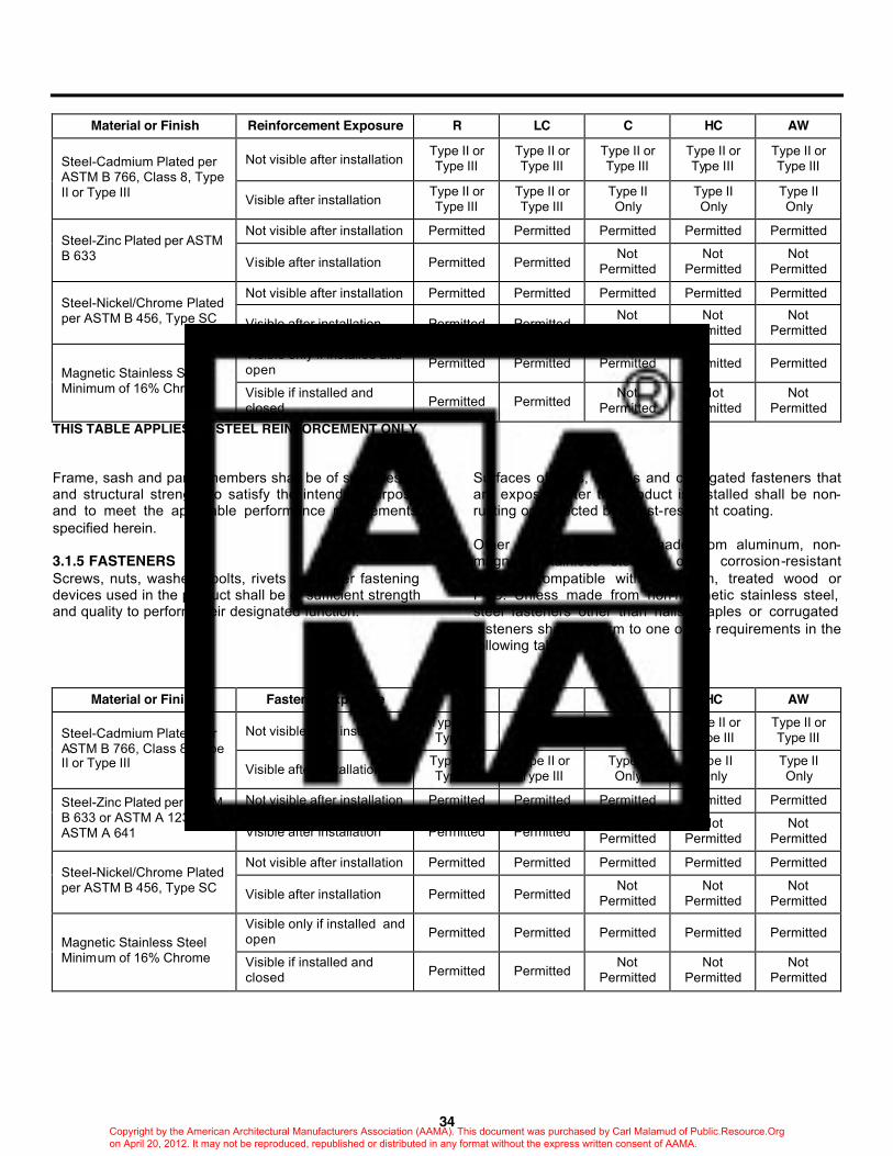
34
Material or Finish Reinforcement Exposure R LC C HC AW
Not visible after installation Type II or Type III
Type II or Type III
Type II or Type III
Type II or Type III
Type II or Type III Steel-Cadmium Plated per
ASTM B 766, Class 8, Type II or Type III Visible after installation
Type II or Type III
Type II or Type III
Type II Only
Type II Only
Type II Only
Not visible after installation Permitted Permitted Permitted Permitted Permitted Steel-Zinc Plated per ASTM B 633 Visible after installation Permitted Permitted
Not Permitted
Not Permitted
Not Permitted
Not visible after installation Permitted Permitted Permitted Permitted Permitted Steel-Nickel/Chrome Plated per ASTM B 456, Type SC Visible after installation Permitted Permitted
Not Permitted
Not Permitted
Not Permitted
Visible only if installed and open Permitted Permitted Permitted Permitted Permitted
Magnetic Stainless Steel Minimum of 16% Chrome Visible if installed and
closed Permitted Permitted Not
Permitted Not
Permitted Not
Permitted THIS TABLE APPLIES TO STEEL REINFORCEMENT ONLY Frame, sash and panel members shall be of such design and structural strength to satisfy the intended purpose and to meet the applicable performance requirements specified herein. 3.1.5 FASTENERS Screws, nuts, washers, bolts, rivets and other fastening devices used in the product shall be of sufficient strength and quality to perform their designated function.
Surfaces of nails, staples and corrugated fasteners that are exposed after the product is installed shall be non-rusting or protected by a rust-resistant coating. Other fasteners shall be made from aluminum, non-magnetic stainless steel or other corrosion-resistant material compatible with aluminum, treated wood or PVC. Unless made from non-magnetic stainless steel, steel fasteners other than nails, staples or corrugated fasteners shall conform to one of the requirements in the following table:
Material or Finish Fastener Exposure R LC C HC AW
Not visible after installation Type II or Type III
Type II or Type III
Type II or Type III
Type II or Type III
Type II or Type III Steel-Cadmium Plated per
ASTM B 766, Class 8, Type II or Type III Visible after installation
Type II or Type III
Type II or Type III
Type II Only
Type II Only
Type II Only
Not visible after installation Permitted Permitted Permitted Permitted Permitted Steel-Zinc Plated per ASTM B 633 or ASTM A 123 or ASTM A 641 Visible after installation Permitted Permitted
Not Permitted
Not Permitted
Not Permitted
Not visible after installation Permitted Permitted Permitted Permitted Permitted Steel-Nickel/Chrome Plated per ASTM B 456, Type SC Visible after installation Permitted Permitted
Not Permitted
Not Permitted
Not Permitted
Visible only if installed and open Permitted Permitted Permitted Permitted Permitted
Magnetic Stainless Steel Minimum of 16% Chrome Visible if installed and
closed Permitted Permitted Not
Permitted Not
Permitted Not
Permitted
Copyright by the American Architectural Manufacturers Association (AAMA). This document was purchased by Carl Malamud of Public.Resource.Org on April 20, 2012. It may not be reproduced, republished or distributed in any format without the express written consent of AAMA.
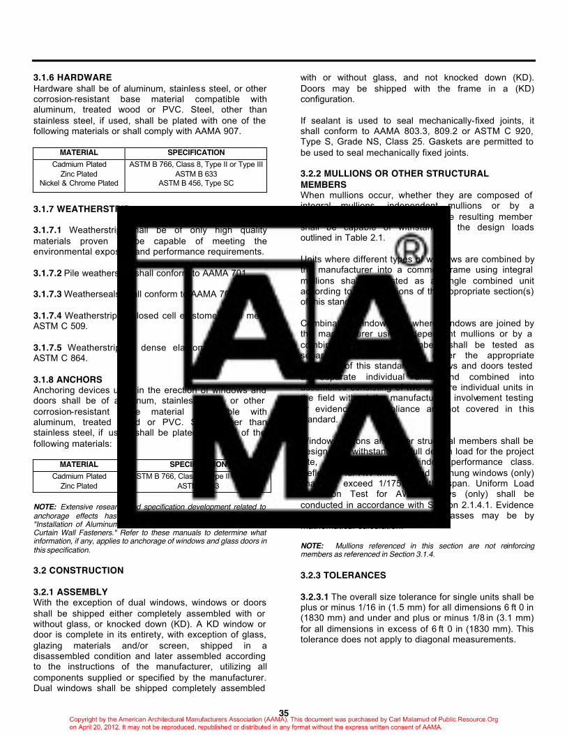
35
3.1.6 HARDWARE Hardware shall be of aluminum, stainless steel, or other corrosion-resistant base material compatible with aluminum, treated wood or PVC. Steel, other than stainless steel, if used, shall be plated with one of the following materials or shall comply with AAMA 907.
MATERIAL SPECIFICATION Cadmium Plated
Zinc Plated Nickel & Chrome Plated
ASTM B 766, Class 8, Type II or Type III ASTM B 633
ASTM B 456, Type SC
3.1.7 WEATHERSTRIP 3.1.7.1 Weatherstrip shall be of only high quality materials proven to be capable of meeting the environmental exposure and performance requirements. 3.1.7.2 Pile weatherstrip shall conform to AAMA 701. 3.1.7.3 Weatherseals shall conform to AAMA 702. 3.1.7.4 Weatherstrip of closed cell elastomer shall meet ASTM C 509. 3.1.7.5 Weatherstrip of dense elastomer shall meet ASTM C 864. 3.1.8 ANCHORS Anchoring devices used in the erection of windows and doors shall be of aluminum, stainless steel, or other corrosion-resistant base material compatible with aluminum, treated wood or PVC. Steel, other than stainless steel, if used, shall be plated with one of the following materials:
MATERIAL SPECIFICATION Cadmium Plated
Zinc Plated ASTM B 766, Class 8, Type II or Type III
ASTM B 633 NOTE: Extensive research and specification development related to anchorage effects has been incorporated into AAMA CWG-1, "Installation of Aluminum Curtain Walls," and AAMA TIR-A9, "Metal Curtain Wall Fasteners." Refer to these manuals to determine what information, if any, applies to anchorage of windows and glass doors in this specification. 3.2 CONSTRUCTION 3.2.1 ASSEMBLY With the exception of dual windows, windows or doors shall be shipped either completely assembled with or without glass, or knocked down (KD). A KD window or door is complete in its entirety, with exception of glass, glazing materials and/or screen, shipped in a disassembled condition and later assembled according to the instructions of the manufacturer, utilizing all components supplied or specified by the manufacturer. Dual windows shall be shipped completely assembled
with or without glass, and not knocked down (KD). Doors may be shipped with the frame in a (KD) configuration. If sealant is used to seal mechanically-fixed joints, it shall conform to AAMA 803.3, 809.2 or ASTM C 920, Type S, Grade NS, Class 25. Gaskets are permitted to be used to seal mechanically fixed joints. 3.2.2 MULLIONS OR OTHER STRUCTURAL MEMBERS When mullions occur, whether they are composed of integral mullions, independent mullions or by a combination of frame members, the resulting member shall be capable of withstanding the design loads outlined in Table 2.1. Units where different types of windows are combined by the manufacturer into a common frame using integral mullions shall be tested as a single combined unit according to the provisions of the appropriate section(s) of this standard. Combination window units where windows are joined by the manufacturer using independent mullions or by a combination of frame members shall be tested as separate/individual windows under the appropriate section(s) of this standard. Windows and doors tested as separate individual units and combined into assemblies consisting of two or more individual units in the field without the manufacturers involvement testing or evidence of compliance are not covered in this standard. Window mullions and other structural members shall be designed to withstand the full design load for the project site, regardless of the window performance class. Deflection for AW windows and HC hung windows (only) shall not exceed 1/175th of the span. Uniform Load Deflection Test for AW Windows (only) shall be conducted in accordance with Section 2.1.4.1. Evidence of compliance for all product classes may be by mathematical calculation. NOTE: Mullions referenced in this section are not reinforcing members as referenced in Section 3.1.4. 3.2.3 TOLERANCES 3.2.3.1 The overall size tolerance for single units shall be plus or minus 1/16 in (1.5 mm) for all dimensions 6 ft 0 in (1830 mm) and under and plus or minus 1/8 in (3.1 mm) for all dimensions in excess of 6 ft 0 in (1830 mm). This tolerance does not apply to diagonal measurements.
Copyright by the American Architectural Manufacturers Association (AAMA). This document was purchased by Carl Malamud of Public.Resource.Org on April 20, 2012. It may not be reproduced, republished or distributed in any format without the express written consent of AAMA.
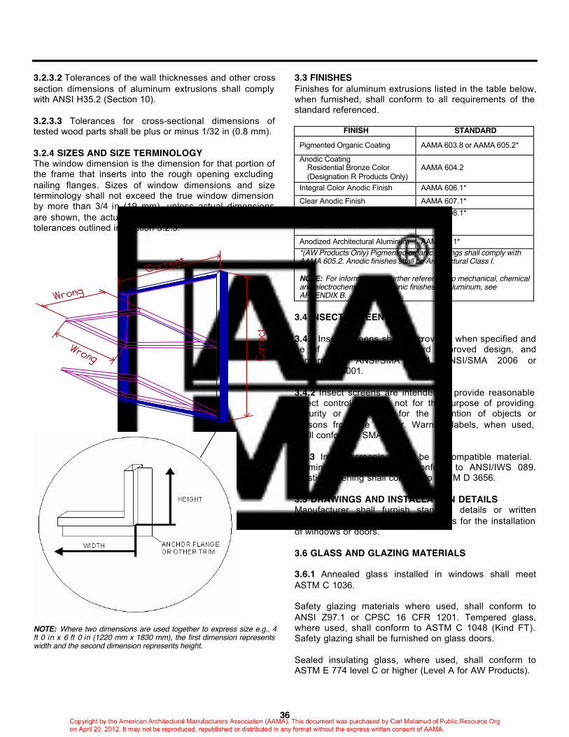
36
3.2.3.2 Tolerances of the wall thicknesses and other cross section dimensions of aluminum extrusions shall comply with ANSI H35.2 (Section 10). 3.2.3.3 Tolerances for cross-sectional dimensions of tested wood parts shall be plus or minus 1/32 in (0.8 mm). 3.2.4 SIZES AND SIZE TERMINOLOGY The window dimension is the dimension for that portion of the frame that inserts into the rough opening excluding nailing flanges. Sizes of window dimensions and size terminology shall not exceed the true window dimension by more than 3/4 in (19 mm), unless actual dimensions are shown, the actual overall dimension being subject to tolerances outlined in Section 3.2.3.
NOTE: Where two dimensions are used together to express size e.g., 4 ft 0 in x 6 ft 0 in (1220 mm x 1830 mm), the first dimension represents width and the second dimension represents height.
3.3 FINISHES Finishes for aluminum extrusions listed in the table below, when furnished, shall conform to all requirements of the standard referenced.
FINISH STANDARD Pigmented Organic Coating AAMA 603.8 or AAMA 605.2* Anodic Coating Residential Bronze Color (Designation R Products Only)
AAMA 604.2
Integral Color Anodic Finish AAMA 606.1*
Clear Anodic Finish AAMA 607.1*
Electrolytically Deposited Color Anodic Finish
AAMA 608.1*
Anodized Architectural Aluminum AAMA 611* *(AW Products Only) Pigmented organic coatings shall comply with AAMA 605.2. Anodic finishes shall be Architectural Class I. NOTE: For information on further references to mechanical, chemical and electrochemical and organic finishes for aluminum, see APPENDIX B.
3.4 INSECT SCREENS 3.4.1 Insect screens shall be provided when specified and be of manufacturer's standard approved design, and conform to ANSI/SMA 1004, ANSI/SMA 2006 or ANSI/SMA 3001. 3.4.2 Insect screens are intended to provide reasonable insect control and are not for the purpose of providing security or to provide for the retention of objects or persons from the interior. Warning labels, when used, shall conform to SMA 7001. 3.4.3 Insect screening shall be of compatible material. Aluminum screening shall conform to ANSI/IWS 089. Plastic screening shall conform to ASTM D 3656. 3.5 DRAWINGS AND INSTALLATION DETAILS Manufacturer shall furnish standard details or written instructions showing recommendations for the installation of windows or doors. 3.6 GLASS AND GLAZING MATERIALS 3.6.1 Annealed glass installed in windows shall meet ASTM C 1036. Safety glazing materials where used, shall conform to ANSI Z97.1 or CPSC 16 CFR 1201. Tempered glass, where used, shall conform to ASTM C 1048 (Kind FT). Safety glazing shall be furnished on glass doors. Sealed insulating glass, where used, shall conform to ASTM E 774 level C or higher (Level A for AW Products).
Copyright by the American Architectural Manufacturers Association (AAMA). This document was purchased by Carl Malamud of Public.Resource.Org on April 20, 2012. It may not be reproduced, republished or distributed in any format without the express written consent of AAMA.
37
Glass furnished by the manufacturer shall meet or exceed the values given in ASTM E 1300 for the design pressure rating of the project. Allowable pressures from the graphs are allowed to be increased as noted for the use of heat strengthened, fully tempered or sealed insulating glass and are required to be decreased as noted for the use of laminated glass. NOTE: In general, the manufacturer will furnish glass as specified by the architect or buyer. For individual projects, the specifier is encouraged to require glass thicknesses appropriate to the glazed area and design pressures for the project as indicated in ASTM E 1300. 3.6.2 CONFORMANCE TESTS Unless otherwise stipulated in this specification, windows and doors submitted for tests under Sections 2 and 4 shall contain glazing intended for use in the product. For products with glass infill, the glass type shall be the minimum strength required for a given load and size based on ASTM E 1300. Glass shall be selected in accordance with the provisions in ASTM E 1300, with the exception that frame or sash deflections, where not specified in this document, are not limited to the glass edge dimension divided by 175. 3.6.2.1 Products tested with a specific glass type shall qualify products of a smaller size manufactured with a different glass type provided the glass conforms to ASTM E 1300, as referenced above. 3.6.2.2 Products tested with plastic materials shall not qualify glass glazing materials, nor products tested with glass qualify plastic glazing materials. 3.6.2.3 Products tested with sealed insulating glass shall not qualify single glazed products. 3.6.3 GLAZING 3.6.3.1 Glazing gaskets shall be of material compatible with aluminum, treated wood or PVC and those sealants and sealing materials used in composite structures which have direct contact with the gasket. The gasket shall be resistant to weathering and maintain a water resistant seal between the glass and the surrounding frame. 3.6.3.2 Back bedding materials using aluminum, treated wood or PVC interior or exterior face stops shall conform to one or more of the following specifications referenced in AAMA 800. Ductile back bedding compounds shall meet AAMA 802.3. Bonding type back bedding compounds shall meet AAMA 805.2.
3.6.3.3 Ductile back bedding tapes shall meet AAMA 804.3. Bonding type back bedding glazing tapes shall meet AAMA 806.3. Cured, rubber-like back bedding glazing tapes shall meet AAMA 807.3. 3.6.3.4 Compatible back bedding compounds and glazing tapes meeting specifications are allowed to be used either singly or in combination. Cellular back-bedding glazing tapes shall meet AAMA 810.1 3.6.4 INTEGRAL VENTILATING SYSTEMS/DEVICES Primary window or glass door products incorporating ventilating systems/devices installed in the unit shall be tested with the ventilating systems/devices installed and the combination unit shall comply with all performance requirements of this document for the window or door type being tested. The specimen shall be tested twice for water penetration and twice for air leakage, once with the venting portion of the ventilating systems/devices in the closed position and again with the venting portion closed and taped or sealed. Air and water performance values for both test modes shall be included in the test report. 3.6.5 GLAZING BEADS Glazing beads or retainers shall be of a material compatible with aluminum, treated wood or PVC. If required to retain the glass, the beads shall be of sufficient strength and fixation to serve this purpose. Thickness of glazing beads is optional, unless specifically called for in a particular product specification. Rigid PVC glazing beads shall be produced from a compound conforming to ASTM D 4216. 3.7 VENETIAN BLINDS IN A DUAL GLAZED WINDOW 3.7.1 When a dual glazed window with a venetian blind between the glass is provided, the operating sash shall consist of the main sash and an access sash providing an air space in which the venetian blind is mounted. 3.7.2 If a venetian blind is included in an enclosed air space, the air space should be vented.
Copyright by the American Architectural Manufacturers Association (AAMA). This document was purchased by Carl Malamud of Public.Resource.Org on April 20, 2012. It may not be reproduced, republished or distributed in any format without the express written consent of AAMA.
REFERENCE STANDARDS
38
3.8 REFERENCE STANDARDS The following standards and specifications are a part of this specification where referenced: AAMA (American Architectural Manufacturers Association) AAMA 303-95 Voluntary Specification for Poly (Vinyl Chloride)(PVC) Exterior Profile Extrusions AAMA 502-90 Voluntary Specification for Field Testing of Windows and Sliding Glass Doors AAMA 603.8-92 Voluntary Performance Requirements and Test Procedures for Pigmented Organic Coatings on Extruded Aluminum AAMA 604.2-77 Voluntary Specification for Residential Color Anodic Finishes AAMA 605.2-92 Voluntary Specification for High Performance Organic Coatings on Architectural Extrusions and Panels AAMA 606.1-76 Voluntary Guide Specifications and Inspection Methods for Integral Color Anodic Finishes for Architectural Aluminum AAMA 607.1-77 Voluntary Guide Specification and Inspection Methods for Clear Anodic Finishes for Architectural Aluminum AAMA 608.1-77 Voluntary Guide Specification and Inspection Methods for Electrolytically Deposited Color Anodic Finishes for Architectural Aluminum AAMA 609-93 Voluntary Guide Specification for Cleaning and Maintenance of Architectural Anodized Aluminum AAMA 610.1-79 Voluntary Guide Specification for Cleaning and Maintenance of Painted Aluminum Extrusions and Curtain Wall Panels AAMA 611-92 Voluntary Standards for Anodized Architectural Aluminum
AAMA 701-92 and AAMA 702-92 Combined Voluntary Specification for Pile Weatherstripping and Voluntary Specification for Replacement Fenestration Weatherseals AAMA 800-92 Voluntary Specifications and Test Methods for Sealants containing the following specifications and test methods:
AAMA 802.3-92 Ductile Back Bedding Glazing Compounds (Type I and Type II) AAMA 803.3-92 Narrow-Joint Seam Sealer (Type I and Type II) AAMA 804.1-92 Ductile Back Bedding Mastic Type Glazing Tapes AAMA 805.2-92 Bonding-Type Back Bedding Compounds AAMA 806.3-92 Bonding-Type Back Bedding Glazing Tapes AAMA 807.1-92 Back Bedding Mastic Type Glazing Tapes AAMA 808.3-92 Exterior Perimeter Sealing Compound AAMA 809.2-92 Non-Drying Sealant AAMA 810.1-92 Expanded Cellular Glazing Tape
AAMA 901.1-90 Voluntary Specification for Rotary Operators in Window Applications AAMA 902-94 Voluntary Specification for Sash Balances AAMA 904.1-87 Voluntary Specifications for Friction Hinges in Window Applications AAMA 906.3-87 Voluntary Specification for Sliding Glass Door Roller Assemblies AAMA 907-93 Voluntary Specification for Corrosion Resistant Coatings on Carbon Steel Components
Copyright by the American Architectural Manufacturers Association (AAMA). This document was purchased by Carl Malamud of Public.Resource.Org on April 20, 2012. It may not be reproduced, republished or distributed in any format without the express written consent of AAMA.

39
AAMA 910-93 Voluntary 'Life Cycle' Specifications and Test Methods for Architectural Grade Windows and Sliding Glass Doors AAMA 1002.10-93 Voluntary Specification for Insulating Storm Products for Windows and Sliding Glass Doors AAMA 1302.5-76 Voluntary Specifications for Forced-Entry Resistant Aluminum Prime Windows AAMA 1303.5-76 Voluntary Specifications for Forced-Entry Resistant Aluminum Sliding Glass Doors AAMA 1503.1-88 Voluntary Test Method for Thermal Transmittance and Condensation Resistance of Windows, Doors and Glazed Wall Sections AAMA 1504-88 Voluntary Standard for Thermal Performance for Windows, Doors and Glazed Wall Sections AAMA 1801-95 Voluntary Specification of the Acoustical Rating of Residential, Commercial, Heavy Commercial and Architectural Windows and Doors and Glazed Wall Sections AAMA AFPA-91 Anodic Finishes/Painted Aluminum AAMA CW-DG-1-96 Curtain Wall Design Guide Manual AAMA CWG-1-89 Installation of Aluminum Curtain Walls AAMA CW-10-82 Care and Handling of Architectural Aluminum from Shop to Site AAMA CW-11-85 Design Windloads for Buildings and Boundary Layer Wind Tunnel Testing AAMA MCWM-1-89 Metal Curtain Wall Manual AAMA SFM-1-87 Aluminum Store Front and Entrance Manual AAMA TIR-A9-91 Metal Curtain Wall Fasteners
AAMA WSG.1-95 Window Selection Guide ANSI (American National Standards Institute) ANSI H35.2-1990 American National Standard Dimensional Tolerances for Aluminum Mill Products ANSI Z34.1-1993 American National Standard for Certification - Third-Party Programs for Products, Processes and Services ANSI Z97.1-1984 (R1994) American National Standard for Safety Glazing Materials Used in Buildings - Safety Performance Specifications and Methods of Test ASCE (American Society of Civil Engineers) ASCE 7-93 Minimum Design Loads for Buildings and Other Structures ASME (American Society of Mechanical Engineers) ANSI/ASME A39.1-1987 Safety Requirements for Window Cleaning ASTM (American Society for Testing and Materials) ASTM A 123-89a Specification for Zinc (Hot-Dipped Galvanized) Coatings on Iron and Steel Products ASTM A 641-92 Specification for Zinc-Coated (Galvanized) Carbon Steel Wire ASTM B 456-94 Specification for Electrodeposited Coatings of Copper Plus Nickel Plus Chromium and Nickel Plus Chromium ASTM B 633-85 (1994) Specification for Electrodeposited Coatings of Zinc on Iron and Steel ASTM B 766-86 (1993) Specification for Electrodeposited Coatings of Cadmium ASTM C 509-94 Specification for Elastomeric Cellular Preformed Gasket and Sealing Material ASTM C 864-93 Specification for Dense Compression Elastomeric Seal Gaskets, Setting Blocks and Spacers
Copyright by the American Architectural Manufacturers Association (AAMA). This document was purchased by Carl Malamud of Public.Resource.Org on April 20, 2012. It may not be reproduced, republished or distributed in any format without the express written consent of AAMA.
40
ASTM C 920-94 Specification for Elastomeric Joint Sealants ASTM C 1036-91 Specification for Flat Glass ASTM C 1048-92 Standard Specification for Heat -Treated Flat Glass---Kind HS, Kind FT Coated and Uncoated Glass ASTM C 1199-91 Test Method for Measuring the Steady State Thermal Transmittance of Fenestration Systems Using Hot Box Methods ASTM D 618-61 (1995) Standard Practice for Conditioning Plastics and Electrical Insulating Materials for Testing ASTM D 3110-91 (E1) Standard Specification for Adhesives Used in Nonstructural Glued Lumber Products ASTM D 3656-94 Standard Specification for Insect Screening and Louver Cloth Woven from Vinyl-Coated-Glass Fiber Yarns ASTM D 4216-92 Specification for Rigid Poly (Vinyl Chloride)(PVC) and Related Plastic Building Products Compounds ASTM D 4726-92 Standard Specification for White Rigid Poly (Vinyl Chloride)(PVC) Exterior-Profile Extrusions Used for Assembled Windows and Doors ASTM D 5572-94 Specification for Adhesive Used for Finger Joint in Nonstructural Lumber Products ASTM E 29-93 Standard Practice for Using Significant Digits in Test Data to Determine Conformance with Specifications ASTM E 283-91 Test Method for Determining the Rate of Air Leakage Through Exterior Windows, Curtain Walls and Doors Under Specified Pressure Differences Across the Specimen ASTM E 330-90 Test Method for Structural Performance of Exterior Windows, Curtain Walls and Doors by Uniform Static Air Pressure Difference
ASTM E 331-93 Test Method for Water Penetration of Exterior Windows, Curtain Walls and Doors by Uniform Static Air Pressure Difference ASTM E 413-87 Classification for Rating Sound Insulation ASTM E 547-93 Test Method for Water Penetration of Exterior Windows, Curtain Walls and Doors by Cyclic Static Air Pressure Differential ASTM E 774-92 Specification for Sealed Insulating Glass Units ASTM E 783-93 Test Method for Field Measurement of Air Leakage Through Installed Exterior Windows and Doors ASTM E 987-94 Standard Test Methods for Deglazing Force of Fenestration Products ASTM E 1300-94 Standard Practice for Determining the Minimum Thickness and Type of Glass Required to Resist a Specified Load ASTM E 1332-90 Standard Classification for Determination of Outdoor-Indoor Transmission Class ASTM E 1423-91 Practice for Determining the Steady State Thermal Transmittance of Fenestration Systems ASTM E 1425-91 Practice for Determining the Acoustical Performance of Exterior Windows and Doors ASTM F 588-85 Test Methods for Resistance of Window Assemblies to Forced Entry Excluding Glazing ASTM F 842-83 Test Methods for Measurement of Forced Entry Resistance of Horizontal Sliding Door Assemblies CAWM (California Association of Window Manufacturers) CAWM 300-96 Forced Entry Resistance Tests for Sliding Glass Doors CAWM 301-90 Forced Entry Resistance Tests for Windows
Copyright by the American Architectural Manufacturers Association (AAMA). This document was purchased by Carl Malamud of Public.Resource.Org on April 20, 2012. It may not be reproduced, republished or distributed in any format without the express written consent of AAMA.
41
CPSC (Consumer Product Safety Commission) 16 CFR 1201-1986 Safety Standard for Architectural Glazing Materials ISWA (Insect Screen Weavers Association) ANSI/IWS 089-1990 Recommended Standards and Specifications for Insect Wire Screening (Wire Fabric) NFRC (National Fenestration Rating Council) NFRC 100-91 Procedure for Determining Fenestration Product Thermal Properties (Currently Limited to U-values) WDMA (Window and Door Manufacturers Association) – formerly NWWDA WDMA Care and Finishing of Wood Windows NWWDA I.S.2-93 Industry Standard for Wood Window Units NWWDA I.S.3-95 Wood Sliding Patio Doors WDMA I.S.4-99 Industry Standard for Water-Repellent Preservative Treatment for Millwork NWWDA I.S.8-95 For Wood Swinging Patio Doors SMA (Screen Manufacturers Association) ANSI/SMA 1004-1987 Specifications for Aluminum Tubular Frame Screens for Windows ANSI/SMA 2006-1987 Specifications for Aluminum Sliding Screen Doors ANSI/SMA 3001-1987 Specifications for Aluminum Swinging Screen Doors
Copyright by the American Architectural Manufacturers Association (AAMA). This document was purchased by Carl Malamud of Public.Resource.Org on April 20, 2012. It may not be reproduced, republished or distributed in any format without the express written consent of AAMA.
SECTION 4 OPTIONAL PERFORMANCE GRADES
42
NOTE: This Section contains additional requirements and tests for products when required by the specifier. It incorporates both higher Uniform Load Structural Test Pressures and higher Water Resistance Test Pressures than those contained in Section 2. As specified below, this Section is to be used in conjunction with Sections 1, 2 and 3. All products tested under this Section are required to conform with all of the particular requirements of Sections 1, 2 and 3 for the product designation under consideration. 4.1 GENERAL Prior to being considered for an optional performance grade, a product must: • comply with the general requirements of Sections 1 and 3 • comply with the Gateway Performance Requirements for the minimum performance grade listed in Table 2.1 • comply with all of the specific product performance requirements listed in Section 2.2 for that product type • comply with all of the appropriate material and component requirements listed in Section 3 After complying with these requirements at the minimum test size for that product, a product is permitted to be tested in the same or a smaller test size for conformance to an Optional Performance Grade as listed in Table 3.1.
OPTIONAL PERFORMANCE GRADES
Water Resistance Test Pressure Design Pressure
Structural Test Pressure R, LC, C and HC AW
Optional Performance
Grade
Applicable Product
Designation lb/ft2 (Pa) lb/ft2 (Pa) lb/ft2 (Pa) lb/ft2 (Pa) 20 25 30 35 40 45 50 55 60 65 70 75 80 85 90
R R
R,LC R,LC,C R,LC,C
R,LC,C,HC,AW R,LC,C,HC,AW R,LC,C,HC,AW R,LC,C,HC,AW R,LC,C,HC,AW R,LC,C,HC,AW R,LC,C,HC,AW R,LC,C,HC,AW R,LC,C,HC,AW R,LC,C,HC,AW
20 25 30 35 40 45 50 55 60 65 70 75 80 85 90
(960) (1200) (1440) (1680) (1920) (2160) (2400) (2640) (2880) (3120) (3360) (3600) (3830) (4080) (4320)
30.0 37.5 45.0 52.5 60.0 67.5 75.0 82.5 90.0 97.5 105.0 112.5 120.0 127.5 135.0
(1440) (1800) (2160) (2520) (2880) (3240) (3600) (3960) (4320) (4680) (5040) (5400) (5750) (6110) (6470)
3.00 3.75 4.50 5.25 6.00 6.75 7.50 8.25 9.00 9.75 10.50 11.25 12.00 12.00 12.00
(150) (180) (220) (260) (290) (330) (360) (400) (440) (470) (510) (540) (580) (580) (580)
— — — — — — — — 8.00 9.00 10.00 11.00 12.00 12.00 12.00 12.00 12.00 12.00 12.00
— — — — — — — — (390) (440) (480) (530) (580) (580) (580) (580) (580) (580) (580)
TABLE 3.1 4.2 CRITERIA A higher than minimum performance grade designation means that the product has successfully been tested to conform to higher uniform load structural and water resistance criteria than the performance levels specified in Table 2.1 and also complies with the air leakage performance levels found in Table 2.1. The structural test pressures shown are for both positive and negative loads. At the conclusion of these tests, there shall be no glass breakage, permanent damage to fasteners, hardware parts, support arms or actuating mechanisms or any other damage which causes the window or door to be inoperable. There shall be no permanent deformation of any main frame, sash, panel or sash member in excess of 0.4% of its span for R, LC, C and HC class products or 0.2% of its span for AW class products. In dual windows the permanent deformation requirement applies to primary window members only.
Where the manufacturer offers or specifies an exterior insect screen, the water resistance test shall be performed both with and without the insect screen in place. Dual windows shall be tested in both the summer and winter modes. Optional performance grades higher than values indicated in the table in increments of 5 psf (240 Pa) may be used. When these higher classes are used, the following relationships shall be followed: Design Pressure = Performance Grade Structural Test Pressure = 1.5 x Design Pressure Water Resistance Test Pressure: R, LC, C & HC = .15 x Positive Design Pressure (12 psf max) AW = .20 x Positive Design Pressure (12 psf max)
Copyright by the American Architectural Manufacturers Association (AAMA). This document was purchased by Carl Malamud of Public.Resource.Org on April 20, 2012. It may not be reproduced, republished or distributed in any format without the express written consent of AAMA.
43
4.3 WATER RESISTANCE TEST With the unit closed and locked, R, LC and C windows and doors shall be subjected to a water resistance test in accordance with ASTM E 547. R, LC and C units shall be tested for four test cycles. Each cycle consisting of five minutes with pressure applied and one minute with pressure released, during which the water spray is continuously applied. In dual windows, the test shall be performed with the unit in both the summer and winter modes. For Optional Performance Grades of 40 or above, C and HC windows and doors shall also be tested for water resistance in accordance with ASTM E 331. For AW windows and doors only, water resistance tests shall be performed in accordance with ASTM E 331 at the test pressure for the desired performance grade both before and after life cycle testing in accordance with AAMA 910. For all grades there shall be no leakage as defined in the test methods ASTM E 331 and ASTM E 547, at the specified test pressure (given in pounds per square foot.) 4.4 UNIFORM LOAD TESTS 4.4.1 UNIFORM LOAD DEFLECTION TEST (AW Architectural Windows and HC Hung Windows Only) The unit shall be subjected to a uniform load at the specified design pressure in Section 4.2 given in pounds per square foot (psf) applied both positive and negative to the surface of the unit. No member shall deflect more than 1/175th of its span. Test shall be conducted in accordance with ASTM E 330. 4.4.2 UNIFORM LOAD STRUCTURAL TEST A minimum uniform structural test pressure as specified (given in pounds per square foot) shall be applied to the unit, first the exterior pressure (positive) and then the interior pressure (negative). The sequence of applying the load may be reversed at the option of the laboratory. Each maximum pressure shall be stabilized and maintained for a period of 10 seconds. Tests shall be conducted in accordance with ASTM E 330. Unit shall be evaluated after each load. Dual windows shall be tested in both the summer and winter modes.
4.5 IDENTIFICATION Products that have been tested and have attained an optional performance grade shall be identified by test size, and rated by replacing the 15 (for R products), 25 (for LC products), 30 (for C products) and 40 (for HC and AW products) with the numerical designation for the highest performance grade level attained during the test. If the test size for optional performance grade is smaller than the minimum test size for the original product type and class, an asterisk (*) shall be added to the performance grade. For example, if a H-HC40 product which has passed the General Requirements of Section 1, the Gateway Performance Requirements in Table 2.1, the Specific Performance Requirements of Sections 2.2, and the Material and Component Requirements of Section 3, is then tested and passes the performance requirements for an Optional Performance Grade 60 according to Section 4, that product is now identified as a H-HC60 (W x H). If the test size for this product at the HC60 optional performance grade were smaller than that required for an H-HC40 specimen, the new designation would be H-HC60* (W x H). Test size is a critical component in the determination of compliance with this standard. Selection of a test size for an Optional Performance Grade is further explained in Section 1.2.1.4.
Copyright by the American Architectural Manufacturers Association (AAMA). This document was purchased by Carl Malamud of Public.Resource.Org on April 20, 2012. It may not be reproduced, republished or distributed in any format without the express written consent of AAMA.
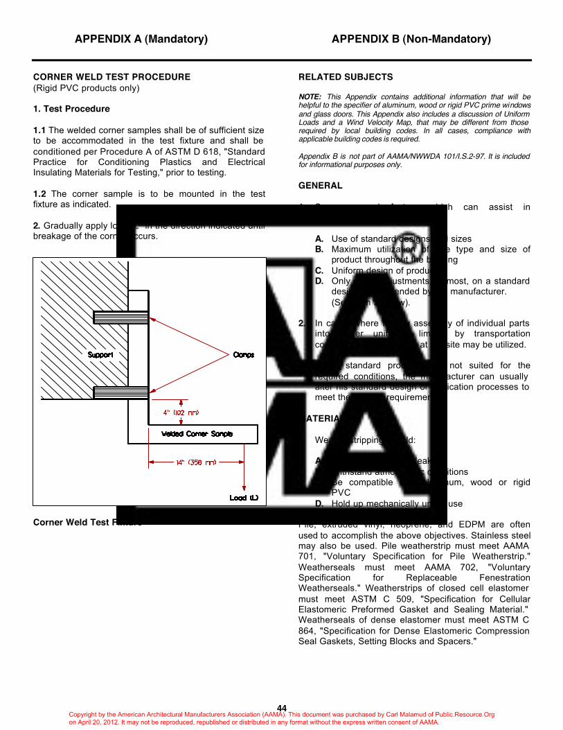
APPENDIX A (Mandatory) APPENDIX B (Non-Mandatory)
44
CORNER WELD TEST PROCEDURE (Rigid PVC products only) 1. Test Procedure 1.1 The welded corner samples shall be of sufficient size to be accommodated in the test fixture and shall be conditioned per Procedure A of ASTM D 618, "Standard Practice for Conditioning Plastics and Electrical Insulating Materials for Testing," prior to testing. 1.2 The corner sample is to be mounted in the test fixture as indicated. 2. Gradually apply load "L" in the direction indicated until breakage of the corner occurs.
Corner Weld Test Fixture
RELATED SUBJECTS NOTE: This Appendix contains additional information that will be helpful to the specifier of aluminum, wood or rigid PVC prime windows and glass doors. This Appendix also includes a discussion of Uniform Loads and a Wind Velocity Map, that may be different from those required by local building codes. In all cases, compliance with applicable building codes is required. Appendix B is not part of AAMA/NWWDA 101/I.S.2-97. It is included for informational purposes only. GENERAL 1. Some general factors which can assist in
maintaining minimum cost are:
A. Use of standard designs and sizes B. Maximum utilization of one type and size of
product throughout the building C. Uniform design of products D. Only minor adjustments, at most, on a standard
design recommended by the manufacturer. (See Item 3 below).
2. In cases where factory assembly of individual parts
into larger units is limited by transportation considerations, assembly at the site may be utilized.
3. When standard products are not suited for the
required conditions, the manufacturer can usually alter his standard design or fabrication processes to meet the specific requirement.
MATERIALS 1. Weatherstripping should:
A. Resist air and water leakage B. Withstand atmospheric conditions C. Be compatible with aluminum, wood or rigid
PVC D. Hold up mechanically under use
Pile, extruded vinyl, neoprene, and EDPM are often used to accomplish the above objectives. Stainless steel may also be used. Pile weatherstrip must meet AAMA 701, "Voluntary Specification for Pile Weatherstrip." Weatherseals must meet AAMA 702, "Voluntary Specification for Replaceable Fenestration Weatherseals." Weatherstrips of closed cell elastomer must meet ASTM C 509, "Specification for Cellular Elastomeric Preformed Gasket and Sealing Material." Weatherseals of dense elastomer must meet ASTM C 864, "Specification for Dense Elastomeric Compression Seal Gaskets, Setting Blocks and Spacers."
Copyright by the American Architectural Manufacturers Association (AAMA). This document was purchased by Carl Malamud of Public.Resource.Org on April 20, 2012. It may not be reproduced, republished or distributed in any format without the express written consent of AAMA.
45
CONSTRUCTION Products should be designed and constructed to provide for adjustment to field variations. Either mechanical joining or welding is satisfactory for PVC when properly performed. Either mechanical joining, brazing or welding is satisfactory for aluminum when properly performed. If brazing or gas welding is used, it is important that all flux be completely removed immediately after the brazing or welding process is completed; otherwise the residue may act as a corrosive substance. Shielded arc-welding and flash welding present no residue problem. Do not solder aluminum. WINDOW CLEANING ANCHORS Window members supporting Window Cleaner Anchor Bolts, when specified, shall be capable of withstanding the impact fall of a Window Cleaner as required in the ANSI/ASME A39.1 standard. Additional reinforcement of the window anchorage to the building may be required. Local codes should be checked for additional requirements concerning window cleaning anchors. ALUMINUM FINISHES Aluminum possesses a silvery, bright and clean looking natural finish. This inherent finish --- an ever-present, usually transparent, inert surface coating of aluminum oxide --- protects aluminum against most atmospheric corrosion. Consequently, architectural aluminum products provide long life with little, if any, maintenance. Atmospheric conditions may, however, affect the surface appearance of natural aluminum by superficial roughening and soiling. If appearance and/or a color other than natural aluminum is a primary consideration, organic coatings may be applied to aluminum. ANODIC FINISHES Like aluminum's natural finish, anodic coatings are composed of aluminum oxide and are an integral part of the aluminum substrate. Careful control permitted by the electrolytic anodizing process, however, provides substantial improvement over the natural oxide film because of the greater thickness, density and hardness of these factory-produced finishes. They may be "clear" ("natural") or colored. Color may be "electrolytically deposited" or "integral." Anodizing is often preceded by chemical treatments to achieve attractive appearance effects. The Aluminum Association classifies architectural anodic coatings as Architectural Class I Coatings and Architectural Class II Coatings depending on coating thickness and recommended use. For further detailed information concerning anodic finishes, the following AAMA publications should be consulted:
AAMA 604.2-77, "Voluntary Specification for Residential Color Anodic Finishes" AAMA 606.1-76, "Voluntary Guide Specifications and Inspection Methods for Integral Color Anodic Finishes for Architectural Aluminum" AAMA 607.1-77, "Voluntary Guide Specification and Inspection Methods for Clear Anodic Finishes for Architectural Aluminum" AAMA 608.1-77, "Voluntary Guide Specification and Inspection Methods for Electrolytically Deposited Color Anodic Finishes for Architectural Aluminum" AAMA 611-92, "Voluntary Standards for Anodized Architectural Aluminum" AAMA CW-DG-1-96, "Curtain Wall Design Guide Manual" AAMA AFPA-91, "Anodic Finishes/Painted Aluminum" ALUMINUM ASSOCIATION, "Designation System for Aluminum Finishes"
ORGANIC FINISHES These include paints, enamels and lacquers. Enamels which may be of either the air-drying or baking type, are the most versatile of these applied finishes. Baked enamel is most frequently used for shop application where it is cured under carefully controlled conditions. A wide range of colors is achieved through pigmentation. For further detailed information concerning organic coatings on aluminum, the following AAMA publications should be consulted:
AAMA 603.8-92, "Voluntary Performance Requirements and Test Procedures for Pigmented Organic Coatings on Extruded Aluminum" AAMA 605.2-92, "Voluntary Specification for High Performance Organic Coatings on Architectural Extrusions and Panels" AAMA AFPA-91, "Anodic Finishes/Painted Aluminum"
Copyright by the American Architectural Manufacturers Association (AAMA). This document was purchased by Carl Malamud of Public.Resource.Org on April 20, 2012. It may not be reproduced, republished or distributed in any format without the express written consent of AAMA.
46
PROTECTION DURING INSTALLATION Aluminum, wood and rigid PVC products are actually "finished" building products, and, like lighting fixtures or bathroom fixtures, should be treated accordingly. All trades should exercise care during handling and installation. For further detailed information consult AAMA CW-10, "Care and Handling of Architectural Aluminum from Shop to Site," and NWWDA's Professional Tips Guideline, "Care and Finishing of Wood Windows." AAMA 609 and 610 may also provide useful information. PROTECTION AND CLEANING The general contractor is responsible for the protection of windows and doors during the course of construction and for cleaning all portions of windows and doors after the painting and finishing of the building is completed. DRAWINGS AND INSTALLATION DETAILS Each manufacturer will normally show in his own literature the best method of installing and anchoring products to the surrounding construction. A manufacturer's representative should be consulted in the event that a special design is used, and shop drawings should be submitted for approval in duplicate if the installation does not follow standard installation details. INSTALLATION It is essential to specify proper workmanship and installation. Minimum requirements are that the work shall be erected plumb, level, straight and true, accurately fitted with tight joints and intersections and adequately reinforced and anchored in place. THERMAL MOVEMENT Rigid PVC has a coefficient of thermal expansion between 0.000022 and 0.000044 inches per inch per degree Fahrenheit (approximately 0.21 in to 0.42 in per 100°F change in temperature per 8 foot length) or between 0.00004 and 0.00008 mm per mm per degree Celsius (approximately 2.0 to 4.0 mm per 50°C change per meter length). Aluminum alloys have a coefficient of thermal expansion of 0.000013 inch per inch per degree Fahrenheit (approximately 1/8 in per 100°F change in temperature per 8 foot length) or 0.000023 mm per mm per degree Celsius (approximately 1.15 mm per 50 °C change per meter length).
Both hardwood and softwood products have a coefficient of thermal expansion between 0.0000017 and 0.0000025 inch per inch per degree Fahrenheit (approximately 0.01 in to 0.02 in per 100°F change in temperature per 8 foot length) or between 0.000002 and 0.000004 mm per mm per degree Celsius (approximately 0.1 to 0.2 mm per 50°C change per meter length). Products must be anchored so that they will not be distorted, nor the fasteners over-stressed from expansion and contraction. ANCHORAGE Recognition and application of the following fundamentals for anchorage will help assure proper installation: A. Anchoring devices which are secured directly to aluminum frame materials, without being insulated from the frame, must be made of aluminum, non-magnetic stainless steel, or other corrosion-resistant materials compatible with aluminum. This is necessary in order to avoid weakening of the aluminum framing members through galvanic corrosion attack, and staining of exposed aluminum surfaces. Steel anchors may be used, provided they are galvanized, zinc plated or finished with other suitable protective coating after fabrication. AAMA's Metal Curtain Wall Manual gives specific recommendations on this subject. B. Anchorage must support the dead load of the window or door, resist applied forces such as positive and negative wind loads and must permit thermal movement resulting from temperature change. C. Anchorage and sill support of the window or door should be adequate to withstand forces from foot traffic, such as the forces exerted by cleaning personnel. D. Design and installation of anchors at jambs of windows which are required to resist forces exerted by cleaning personnel must receive special attention.
Copyright by the American Architectural Manufacturers Association (AAMA). This document was purchased by Carl Malamud of Public.Resource.Org on April 20, 2012. It may not be reproduced, republished or distributed in any format without the express written consent of AAMA.
47
DISSIMILAR MATERIALS A. Where aluminum surfaces may come in contact with metals other than stainless steel, zinc, cadmium or small areas of white bronze, keep aluminum surfaces from direct contact with incompatible metals. This is achieved by providing suitable protection coatings of paint, by using good quality caulking material between the surfaces, by using non-absorptive plastic or elastomeric tapes or gaskets, or in the case of steel, using a sufficiently thick galvanized coating. Coatings containing lead pigmentation must be avoided. B. Steel anchors and other types of unexposed clips may be zinc or cadmium plated or finished with other suitable protective coating after fabrication. C. Dissimilar metals should be painted if used in locations where drainage from them passes over aluminum. D. Paint aluminum surfaces in contact with lime mortar, concrete or other masonry materials with alkali resistant coatings. PERIMETER CAULKING The architect or sealant manufacturer should be consulted to assist in the proper selection of materials and their application. GLAZING Aluminum, wood and PVC products can be prepared for either inside or outside glazing. Consult individual manufacturers to determine their respective glazing details. PERFORMANCE REQUIREMENTS The performance requirements included in Section 2 of this specification were developed by AAMA and NWWDA for use by the entire industry after carrying out experimental tests and observing performance requirements, and were established in preference to specifically designated physical characteristics. Those required of all products are highlighted below. AIR LEAKAGE The standard method of expressing air leakage is in cubic feet per minute per square foot of area (cfm/ft2) [cubic meters per hour per square meter of area (m3/h•m2)] for a given pressure differential across the product when it is adjusted for normal operation.
WATER RESISTANCE Resistance to water leakage can be an important consideration in the appearance and maintenance of the product and surrounding areas and, in some cases, the control of humidity. The test methods used in this standard for determining water resistance are ASTM E 331, "Test Method for Water Penetration of Exterior Windows, Curtain Walls and Doors by Uniform Static Air Pressure Difference," and ASTM E 547, "Test Method for Water Penetration of Exterior Windows, Curtain Walls and Doors by Cyclic Static Air Pressure Differential." These nationally recognized standards require the uniform application of water against the exterior surface of the product at a rate of 5 gal/hr•ft2 (3.40 L/min•m2). This rate corresponds to a rainfall of 8 in (200 mm) per hour. The severity of this test is seen when it is realized that, according to U.S. Department of Commerce, Weather Bureau Technical Paper No. 40-1963, "Rainfall Frequency Atlas of the United States for Durations from 30 Minutes to 24 Hours and Return Periods from 1 to 100 Years", on rainfall frequency published by the National Weather Service, the greatest rainfall expected anywhere in the contiguous 48 United States for a one-hour period during a span of 50 years is less than 5 in (125 mm) per hour. Since excessive water leakage may jeopardize furnishings and equipment, it is important to design and select products that will not permit significant leakage under normal service conditions. It is generally accepted, however, that water leakage can be tolerated during periods combining high winds and heavy rains. In recognition of this, water resistance is generally determined at a pressure less than the Design Pressure. The required Water Resistance Test is commonly conducted at a pressure equal to 15% of the Design Pressure for R, LC, C and HC products (20% for AW products) but never less than 2.86 psf (140 Pa) nor more than 12 psf (580 Pa).
Copyright by the American Architectural Manufacturers Association (AAMA). This document was purchased by Carl Malamud of Public.Resource.Org on April 20, 2012. It may not be reproduced, republished or distributed in any format without the express written consent of AAMA.
48
FIELD TESTING AAMA has developed a short form specification to simplify specifying field air leakage and water resistance testing. The document is AAMA 502, "Voluntary Specification for Field Testing of Windows and Sliding Glass Doors." The inside cover of the AAMA 502 specification has been duplicated as follows:
SHORT FORM FIELD TESTING SPECIFICATION HOW TO USE THE SHORT FORM FIELD TESTING SPECIFICATION To simplify the writing of field testing specifications for windows and sliding glass doors, AAMA and NWWDA have prepared a "Short Form Specification," which is recommended whenever possible. It may be used by merely inserting the following paragraph(s) into the project specifications. SHORT FORM FIELD TESTING SPECIFICATION (Insert windows and/or glass doors) shall be field tested in accordance with AAMA 502, "Voluntary Specification for Field Testing of Windows and Sliding Glass Doors," using Test Method . NOTE: Test Method A will be used unless Test Method B is selected here. (See AAMA 502 for descriptions of both test methods.) AAMA 502 specifies air leakage and water resistance field testing for three (3) windows immediately after installation begins. Default performance values for air leakage and water penetration are also specified. Any of the following optional paragraphs may be added to modify the standard specification, however, consideration should be given to the cost of additional testing. 1. Test additional windows for air leakage and water
penetration as specified at percent of the window installation.
2. Air leakage tests shall be conducted at a uniform static test pressure
of psf (Pa). The maximum allowable rate of air leakage shall not exceed cfm (m3/h) per ft2 (m2).
3. Water penetration tests shall be conducted at a static test pressure
of psf (Pa).
4. The following shall also be field tested:
A. (Insert the appropriate test(s) and procedure(s).
DESIGN WINDLOAD The pressure exerted by the wind on a wall component is assumed to be uniformly distributed across the surface of the product. Its magnitude is dependent on such factors as the geographical location, shape and surroundings of the building as well as the height of the product above grade and its location within the wall. The jurisdiction where the windows or doors will be installed should be contacted to determine the wind load requirements that have been adopted and are enforced. For additional information on wind loads on buildings the following publications should be consulted: CW-11, "Design Windloads for Buildings and Boundary Layer Wind Tunnel Testing" ASCE 7-93, "Minimum Design Loads for Buildings and Other Structures"
Copyright by the American Architectural Manufacturers Association (AAMA). This document was purchased by Carl Malamud of Public.Resource.Org on April 20, 2012. It may not be reproduced, republished or distributed in any format without the express written consent of AAMA.
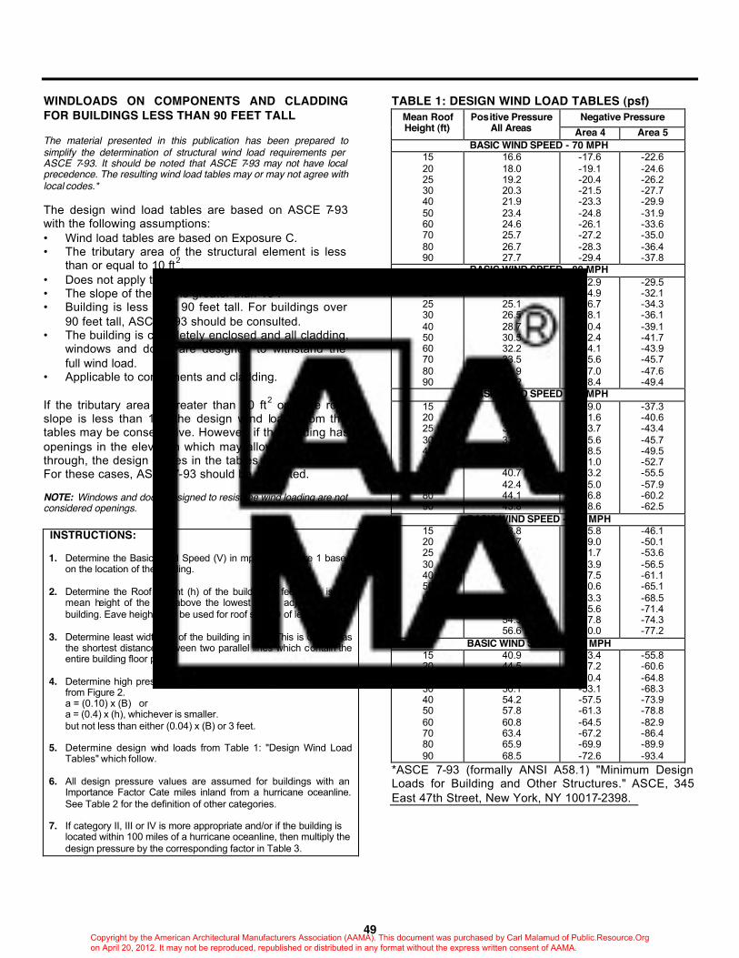
49
WINDLOADS ON COMPONENTS AND CLADDING FOR BUILDINGS LESS THAN 90 FEET TALL The material presented in this publication has been prepared to simplify the determination of structural wind load requirements per ASCE 7-93. It should be noted that ASCE 7-93 may not have local precedence. The resulting wind load tables may or may not agree with local codes.* The design wind load tables are based on ASCE 7-93 with the following assumptions: • Wind load tables are based on Exposure C. • The tributary area of the structural element is less
than or equal to 10 ft2. • Does not apply to roof areas. • The slope of the roof is greater than 10°. • Building is less than 90 feet tall. For buildings over
90 feet tall, ASCE 7-93 should be consulted. • The building is completely enclosed and all cladding,
windows and doors are designed to withstand the full wind load.
• Applicable to components and cladding. If the tributary area is greater than 10 ft2 or if the roof slope is less than 10°, the design wind loads from the tables may be conservative. However, if the building has openings in the elevation which may allow wind to pass through, the design values in the tables may be too low. For these cases, ASCE 7-93 should be consulted. NOTE: Windows and doors designed to resist the wind loading are not considered openings.
INSTRUCTIONS: 1. Determine the Basic Wind Speed (V) in mph from Figure 1 based
on the location of the building. 2. Determine the Roof Height (h) of the building in feet. This is the
mean height of the roof above the lowest grade adjacent to the building. Eave height may be used for roof slope θ of less than 10o.
3. Determine least width (B) of the building in feet. This is defined as
the shortest distance between two parallel lines which contain the entire building floor plan.
4. Determine high pressure outside corner loading zones (a) in feet
from Figure 2. a = (0.10) x (B) or a = (0.4) x (h), whichever is smaller. but not less than either (0.04) x (B) or 3 feet.
5. Determine design wind loads from Table 1: "Design Wind Load
Tables" which follow. 6. All design pressure values are assumed for buildings with an
Importance Factor Cate miles inland from a hurricane oceanline. See Table 2 for the definition of other categories.
7. If category II, III or IV is more appropriate and/or if the building is
located within 100 miles of a hurricane oceanline, then multiply the design pressure by the corresponding factor in Table 3.
TABLE 1: DESIGN WIND LOAD TABLES (psf) Negative Pressure Mean Roof
Height (ft) Positive Pressure
All Areas Area 4 Area 5 BASIC WIND SPEED - 70 MPH
15 20 25 30 40 50 60 70 80 90
16.6 18.0 19.2 20.3 21.9 23.4 24.6 25.7 26.7 27.7
-17.6 -19.1 -20.4 -21.5 -23.3 -24.8 -26.1 -27.2 -28.3 -29.4
-22.6 -24.6 -26.2 -27.7 -29.9 -31.9 -33.6 -35.0 -36.4 -37.8
BASIC WIND SPEED - 80 MPH 15 20 25 30 40 50 60 70 80 90
21.6 23.5 25.1 26.5 28.7 30.5 32.2 33.5 34.9 36.2
-22.9 -24.9 -26.7 -28.1 -30.4 -32.4 -34.1 -35.6 -37.0 -38.4
-29.5 -32.1 -34.3 -36.1 -39.1 -41.7 -43.9 -45.7 -47.6 -49.4
BASIC WIND SPEED - 90 MPH 15 20 25 30 40 50 60 70 80 90
27.4 29.8 31.8 33.5 36.3 38.7 40.7 42.4 44.1 45.8
-29.0 -31.6 -33.7 -35.6 -38.5 -41.0 -43.2 -45.0 -46.8 -48.6
-37.3 -40.6 -43.4 -45.7 -49.5 -52.7 -55.5 -57.9 -60.2 -62.5
BASIC WIND SPEED - 100 MPH 15 20 25 30 40 50 60 70 80 90
33.8 36.7 39.3 41.4 44.8 47.7 50.3 52.4 54.5 56.6
-35.8 -39.0 -41.7 -43.9 -47.5 -50.6 -53.3 -55.6 -57.8 -60.0
-46.1 -50.1 -53.6 -56.5 -61.1 -65.1 -68.5 -71.4 -74.3 -77.2
BASIC WIND SPEED - 110 MPH 15 20 25 30 40 50 60 70 80 90
40.9 44.5 47.5 50.1 54.2 57.8 60.8 63.4 65.9 68.5
-43.4 -47.2 -50.4 -53.1 -57.5 -61.3 -64.5 -67.2 -69.9 -72.6
-55.8 -60.6 -64.8 -68.3 -73.9 -78.8 -82.9 -86.4 -89.9 -93.4
*ASCE 7-93 (formally ANSI A58.1) "Minimum Design Loads for Building and Other Structures." ASCE, 345 East 47th Street, New York, NY 10017-2398.
Copyright by the American Architectural Manufacturers Association (AAMA). This document was purchased by Carl Malamud of Public.Resource.Org on April 20, 2012. It may not be reproduced, republished or distributed in any format without the express written consent of AAMA.
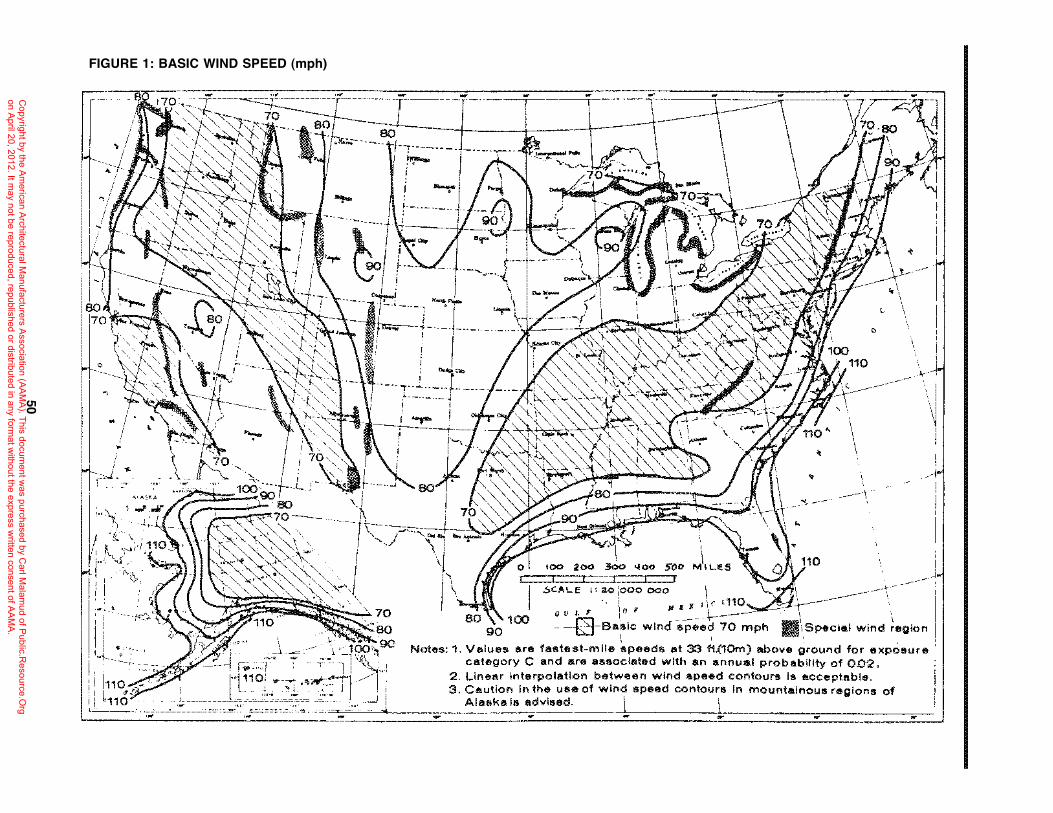
50
FIGURE 1: BASIC WIND SPEED (mph)
Copyright by the A
merican A
rchitectural Manufacturers A
ssociation (AA
MA
). This document w
as purchased by Carl M
alamud of P
ublic.Resource.O
rg on A
pril 20, 2012. It may not be reproduced, republished or distributed in any form
at without the express w
ritten consent of AA
MA
.
i " , ,
, , V
t . ~·-T~ i(J), l-i
: I·
('
. il . 1""
."
2.1.. -
----
--- .::.--------~~-\ \
IF - -.~ . -.'.'--.'' { B '7°"iii~~E= oo~=~,l, -'1' , "'i' ,'>!, :11\\ I' ,."... I ... ':'x-, "- ,<"" I \ - -- '''{v~~'- ' , \
/"~~,,,~ -"'1 -i -- - ',,,, '..,.. @ ,! ' ''i"",,~,,-t, "-- -! --.-,I i ','i""'-<~'i', -_." 90 1
il" "1..',"'-",,-,),"-' T,------. 'It- '--,""'-}", , ~ I ., 1,' --'--.; ,~').. ," ,-, •• """ ,.. , i ~ -'_-::-"'~. ',' ~') ,I I ! , \ ' -'<',~"-., .,. I' ,--" , - .' "-,,_, ~ ....,--' " 00 I -. i : !" ---~--, __ J ,"'i,~",~",-i I ; - ..... ~-.~ :
, \ ----,' 'i I' ''j , ' - I " I.... '--, '-,", -,,:....~ -.+-- ~ ~ 1 ""'~-80 ,... J3 '''--.0.' ! (-' ----, ~-.""'" \
~'70 I ' ,80 ,ii < --- ':{, ~_ i, I "T" 1-"
" ' " 'f __ . _,,_. '1 ~ • 'I ", "'J: ' I : ~"~ ! ""~" ' I I., " I, ""-~-~ I I I, \! ,-- ';. : "'\"', \1- "~"_' I _ ''',I' " ,1 - ~).:,'i,,, ; -"'" '~ '1"- - 'C-' 'r -- ,',I - ~";'" ,-- ,----,-----, -----
, "' I - -r:- --. '__ 'j' "-Z><-'" r------- j , I ," , / -_ "\"" ,.J\ I..... I • .. 'fi'.. ' " ',,", -'. ~-t- --"';'--------r
, f-~~' ""':-<- i,,' ,', ~ i'~. .. 1, I I '~ , '
i I Ii \ ~I ':"0 i I 70." '
~ • , - '\",,-1 : . c·., •• L . \ _ ,-', 'i " i 1,:' ,,;;-:, __ , ;" 100>-·L,.L.' '" '~ ""_.,....J ....... 80 , , ,"" 1?'):;:: :;:90 I - , 1
~ 80 ""I .' • " r ~70---."-__ ; 70:---.,','
~'V -,
E - ' ... -
:) ! '-. & ....
.. " \ -.lJ
-- }
, , -\.-J>-'
.-- '" \ , , \
o
\ , •
"-- ----'j'
~;S;~~::,\~ 1\<J~"~1-~ ,~:-. "--. '<-' ~::::__! II " ''''';::~:''~~'-'''! ",
.f,> ~~ _ 3~O ~)\LIOS ~~ (jJ110 ___ .
3(.ALE 1':1..0 ;000 000 ~,.- I _-- --.~ -
; /I'll' J'I,f '110 ..-:;:J t------
" ---1, , '
"',\1 ,
_"1'
,,~ 1\, .. ,." "", 70 o tJ I Flo' -\---_____ I '
., ' , ''', ,80 g"O:O --0-Bn.~iC wind -I!.-p'eed 70 mph lif,SpeCisJ wind ~eglOn h~ .c", '~ ~~9C . '
I i ~ '1'" _1 ~,,' i. '_F':iO;:, Notes: 1. Values are fastest-mile speeds 4!lt 33 ft,(1Om) above ground for exposure W'" ... ~ I ..... ",'! -;,'~, 'I i '~~s.,,,! category C Ilnd are Ils50clated with an annual probability of 0.0'2,
i I ~,' 1"'l'10: '#'-""'": • .,W':'.~~) /'1 2. Ltne~r Interpolation be~ween wind speed contours Is acceptable. i L110
",- , l _ '. '., ';", _"~~ __ ,~:." J, 3. Caution In th~ use of wmd speed contou~1$ In mountainous regions of :_, _~ ,,, __ ,, __ "_~~==~~,~,~~::~-~~=::~:~--~~~ --',_.-.- .. ..J... Alaska Is adVIsed. L __ .. .. - ~==c±===C==, .. __ . __
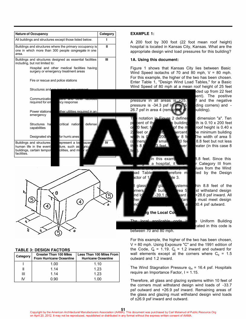
51
Nature of Occupancy Category All buildings and structures except those listed below. I
Buildings and structures where the primary occupancy is one in which more than 300 people congregate in one area.
II
Buildings and structures designed as essential facilities including, but not limited to: Hospital and other medical facilities having surgery or emergency treatment areas Fire or rescue and police stations Structures and equipment in government Communication centers and other facilities required for emergency response Power stations and other utilities required in an emergency Structures having critical national defense capabilities Designated shelters for hurric anes
III
Buildings and structures that represent a low hazard to human life in the event of failure, such as agriculture buildings, certain temporary facilities, and minor storage facilities.
IV
TABLE 3: DESIGN FACTORS Category Greater Than 100 Miles
From Hurricane Oceanline Less Than 100 Miles From
Hurricane Oceanline I II III IV
1.00 1.14 1.14 0.90
1.10 1.23 1.23 1.00
EXAMPLE 1: A 200 foot by 300 foot (22 foot mean roof height) hospital is located in Kansas City, Kansas. What are the appropriate design wind load pressures for this building? 1A. Using this document: Figure 1 shows that Kansas City lies between Basic Wind Speed isotachs of 70 and 80 mph, V = 80 mph. For this example, the higher of the two has been chosen. Enter Table 1, "Design Wind Load Tables," for a Basic Wind Speed of 80 mph at a mean roof height of 25 feet (the mean roof height has been rounded up from 22 feet to the next higher table increment). The positive pressure in all areas is +25.1 psf and the negative pressure is -34.3 psf in area 5 (building corners) and -26.7 psf in area 4 (remainder of the building). The notation in Figure 2 defines the dimension "a". Ten percent of the minimum building width is 0.10 x 200 feet or 20 feet; forty percent of the mean roof height is 0.40 x 22 feet or 8.8 feet; four percent of the minimum building width is 0.04 x 200 feet or 8 feet. The width of area 5 (corners) is the smaller of 20 feet or 8.8 feet but not less than 8 feet or 3 feet, whichever is greater (in this case 8 feet). Therefore, in this example, "a" is 8.8 feet. Since this building is a hospital, it falls under Category III from Table 2 (importance factor). The values from the Wind Load Tables are therefore multiplied by the Design Factor of 1.14 from Table 3. All glass and glazing systems within 8.8 feet of the corners of the building (area 5) must withstand design wind loads of -39.1 psf outward and +28.6 psf inward. All other areas of the building (area 4) must meet design wind loads of +28.6 psf inward and -30.4 psf outward. 1B. Using the Local Code: The local applicable code is the Uniform Building Code. The Basic Wind Speed indicated in this code is between 70 and 80 mph. For this example, the higher of the two has been chosen, V = 80 mph. Using Exposure "C" and the 1991 edition of the Code, Ce = 1.19. Cq = 1.2 inward and outward for wall elements except at the corners where Cq = 1.5 outward and 1.2 inward. The Wind Stagnation Pressure q e = 16.4 psf. Hospitals require an Importance Factor, I = 1.15. Therefore, all glass and glazing systems within 10 feet of the corners must withstand design wind loads of -33.7 psf outward and +26.9 psf inward. Remaining areas of the glass and glazing must withstand design wind loads of ±26.9 psf inward and outward.
Copyright by the American Architectural Manufacturers Association (AAMA). This document was purchased by Carl Malamud of Public.Resource.Org on April 20, 2012. It may not be reproduced, republished or distributed in any format without the express written consent of AAMA.

52
Since the design wind loads from the local code are less severe, the designer might be well served to determine the design values required by the local code. EXAMPLE 2: The same 200 foot by 300 foot (22 foot mean roof height) hospital is located in Philadelphia, Pennsylvania. What are the appropriate design wind load pressures for this building? 2A. Using this document: Figure 1 shows that Philadelphia lies less than 100 miles from a hurricane coastline and between Basic Wind Speed isotachs of 70 and 80 mph. For this example, the higher of the two has been chosen, V = 80 mph. Enter Table 1, "Design Wind Load Table" for a Basic Wind Speed of 80 mph at a mean roof height of 25 feet (the mean roof height has been rounded up from 22 feet to the next highest table increment). The positive pressure in all areas is +25.1 psf and the negative pressure is -34.3 psf in area 5 (building corners) and -26.7 psf in area 4 (remainder of the building). The notation in Figure 2 defines the dimension "a." Ten percent of the minimum building width is 0.10 x 200 feet or 20 feet; forty percent of the mean roof height is 0.40 x 22 feet or 8.8 feet; four percent of the minimum building width is 0.04 x 200 feet or 8 feet. The width of area 5 (corners) is the smaller of 20 feet or 8.8 feet but not less than 8 feet or 3 feet, whichever is greater (in this case 8 feet). Therefore, in this example, "a" is 8.8 feet. Since this building is a hospital, it falls into Category III from Table 2 (importance factor). The values from the Wind Load Tables are therefore multiplied by the Design Factor of 1.23 (at hurricane oceanline) from Table 3. All glass and glazing systems within 8.8 feet of the corners of the building (area 5) must withstand design wind loads of -42.2 psf outward and +30.9 psf inward. All other areas of the building (area 4) must meet design wind loads of +30.9 psf inward and -32.8 psf outward. 2B. Using the Local Code: The local applicable code is the BOCA National Building Code. The Basic Wind Speed indicated in the code is between 70 and 80 mph. For this example, the higher of the two was chosen. According to the 1990 edition of this Code, if the tributary area of the building element is less than 700 square feet (the AAMA document is based upon 10 square feet), the glass and glazing members must be designed using ASCE 7-88. This would result in the same design wind loads as calculated in part A above.
EXAMPLE 3: The same 200 foot by 300 foot (22 foot mean roof height) hospital is located in Corolla City, Currituck County, North Carolina. What are the appropriate design wind load pressures for this building? 3A. Using this document: Figure 1 shows that Corolla City lies less than 100 miles from a hurricane coastline and between Basic Wind Speed isotachs of 90 and 100 mph. For this example, the higher of the two has been chosen, V = 100 mph. Enter Table 1, "Design Wind Load Tables" for a Basic Wind Speed of 100 mph at a roof height of 25 feet (the mean roof height has been rounded up from 22 feet to the next highest table increment). The positive pressure in all areas is +39.3 psf and the negative pressure is -53.6 psf in area 5 (building corners) and -41.7 psf in area 4 (remainder of the building). The notation in Figure 2 defines the dimension "a." Ten percent of the minimum building width is 0.10 x 200 feet or 20 feet; forty percent of the mean roof height is 0.40 x 22 feet or 8.8 feet; four percent of the minimum building width is 0.04 x 200 feet or 8 feet. The width of area 5 (corners) is the smaller of 20 feet or 8.8 feet but not less than 8 feet or 3 feet, whichever is greater (in this case 8 feet). Therefore, in this example, "a" is 8.8 feet. Since this building is a hospital, it falls into Category III from Table 2 (importance factor). The values from the Wind Load Tables are therefore multiplied by the Design Factor of 1.23 (at hurricane oceanline) from Table 3. All glass and glazing systems within 8.8 feet of the corners of the building (area 5) must withstand design wind loads of -65.9 psf outward and +48.3 psf inward. All other areas of the building (area 4) must meet design wind loads of +48.3 psf inward and -51.3 psf outward. 3B. Using the Local Code: From the 1991 North Carolina State Building Code, Table 1205.2A and Figure 1205.3, the Basic Design Wind Velocity for Corolla City is 120 mph. Then, from Table 1205.2B, velocity pressure can found as 29 psf for 120 mph basic design wind velocity. From statement 1205.3.3, for tributary areas of 200 ft2 and less, the velocity pressure should be increased by 15% and becomes 29 x 1.15 = 33.35 psf. The shape factor can be obtained from Table 1205.5 as ±1.1. Therefore, the positive pressure in all areas shall be 33.35 x 1.1 = +36.7 psf and the negative pressure in all areas shall be 33.35 x (-1.1) = -36.7 psf. The local building code is again less severe in this example.
Copyright by the American Architectural Manufacturers Association (AAMA). This document was purchased by Carl Malamud of Public.Resource.Org on April 20, 2012. It may not be reproduced, republished or distributed in any format without the express written consent of AAMA.
53
CONDENSATION The resistance of windows and doors to condensation is important in buildings which contain activities that periodically release significant amounts of water vapor and which may or may not have humidification during winter months. The potential for condensation is increased in relation to the severity of cold weather conditions. The interior humidity level at which condensation occurs will vary for a specific product. Conditions which may affect interior surface temperatures of windows and doors and, thus, the amount of condensation, include (but are not necessarily limited to) the following: A. Type of wall construction and material(s) used
therein. B. For cavity walls, location of thermal break in
aluminum products with respect to the wall cavity. C. Closed drapes and/or shades. D. Depth of reveal (recess at stool, jambs and head). E. Positive (exterior) and or negative (interior)
pressures in the building which may increase leakage of cold air.
1. Height of product above grade 2. Location of surrounding buildings and type of
surrounding terrain. 3. Wind Velocity 4. Operation of HVAC Equipment
F. Solar radiation and orientation G. Water vapor pressure and temperature indoors H. Water vapor pressure and temperature outdoors
The Condensation Resistance Factor (CRF) is a rating number obtained under standard test conditions which allows the prediction, within reasonable accuracy, of the condensation performance of a window or door. While the CRF rating number that is obtained by the procedure outlined in AAMA 1503.1 "Voluntary Test Method for Thermal Transmittance and Condensation Resistance of Windows, Doors and Glazed Wall Sections," is not an absolute value (i.e., it may not predict the first location where condensation occurs), the CRF does provide a comparative performance rating for similar products and permits the determination of the conditions beyond which an objectionable amount of condensation may occur. The selection of the proper Condensation Resistance Factor is dependent upon three main variables; the exterior design temperature, the interior air temperature and the inside relative humidity. The average interior relative humidity at the winter exterior design temperature determines the CRF rating that a window or door should have to perform satisfactorily. Interior relative humidity tends to be reduced as a result of the lower water vapor pressure of cold exterior air. Generally, colder exterior temperatures result in a greater difference in vapor pressure. For this reason, interior relative humidity levels are usually reduced as exterior air temperatures decrease during the winter. While higher humidity conditions may be considered more comfortable, they are undesirable for other reasons. High humidity levels cause condensation to form on windows and doors and increase the chances of water vapor condensing in wall and ceiling insulation, deteriorating wood framing and sheathing, exterior paint failure and buckling of roof sheathing. To be safe, humidity levels must be moderate and controlled. Reference can be made to Chart A which plots winter temperatures based on ASHRAE data for 97.5% design values. The winter outdoor design temperature should be selected first.
Copyright by the American Architectural Manufacturers Association (AAMA). This document was purchased by Carl Malamud of Public.Resource.Org on April 20, 2012. It may not be reproduced, republished or distributed in any format without the express written consent of AAMA.

54
CHART A
Temperature data for specific locations are given in Weather Data and Design Considerations, "ASHRAE Handbook of Fundamentals" published by American Society of Heating, Refrigeration and Air Conditioning Engineers, Inc. Maximum recommended inside relative humidity levels for a range of winter outdoor design temperatures are given in Table 4. TABLE 4: MAXIMUM RECOMMENDED HUMIDITY LEVELS
OUTSIDE AIR TEMPERATURE INSIDE RELATIVE HUMIDITY -20°F or Below Not Over 15%
-20°F to-10 Not Over 20% -10°F to 0 Not Over 25%
0°F to 10 Not Over 30% 10°F to 20 Not Over 35% 20°F to 40 Not Over 40%
Based on Engineering Studies at 70°F conducted at the University of Minnesota Laboratories.
Relative humidity levels above these are not recommended at the low outside temperatures indicated, unless special provisions are taken in building construction. Minimum Condensation Resistance Factors are selected from Table 5 for particular sets of design conditions. Locate the recommended relative humidity at the top of the chart and the exterior design temperature on the left hand side of the chart. The CRF number at the intersection of the inside relative humidity and exterior design temperature is the minimum rating which should prevent an objectionable amount of condensation. For example, a CRF rating of 46 would be required for an exterior design temperature of minus 10 degrees Fahrenheit and an inside relative humidity of 20%.
TABLE 5: MINIMUM RECOMMENDED CONDENSATION RESISTANCE FACTOR (CRF)
(Interior Air Temperature = 68°F . . . Wind Velocity = 15 mph)
OUTSIDE AIR TEMPERATURE
MAXIMUM RECOMMENDED INSIDE RELATIVE
HUMIDITY
INSIDE RELATIVE HUMIDITY
15% 20% 25% 35% 40% -20°F -10°F 0°F 10°F 20°F
20 25 30 35 40
46 39 30 17 0
52 46 39 29 16
57 52 45 37 25
-- 60 57 50 40
-- -- 61 57 48
HEAT TRANSMISSION When there is a temperature difference across a window or door, heat will flow from the high temperature side of the product to the low temperature side. During the winter, heat will flow from the warm inside air to the cold outside air. During the summer, heat will flow in the opposite direction. Heat flow due to temperature difference is referred to as conductive heat flow. The rate of conductive heat flow from air to air through a window or door is determined by the thermal resistance of the glass and framing plus the air film resistance at the inner and outer surfaces of the glass and framing. In the case of single glass the resistance to heat flow is due almost entirely to the resistance at the surfaces. This resistance from surface to air depends on surface emissivity and the velocity of air across the surface. Higher emissivity results in lower resistance. Higher air velocity produces lower resistance. The effect is most noticeable at low velocities from still air up to about 15 mph. The total resistance to heat flow across the frame and glass area of a window or door is the sum of the inside surface to air resistance, the resistance of the frame and the glass itself, and the outside surface to air resistance. The reciprocal of the sum of these resistances is the conductance. Unit air-to-air heat conductance is also called heat transmittance. It is the heat which is conducted through one square foot of window area in one hour when the temperature difference across the window is 1°F. This is written as BTU/h•ft2•F and is referred to as the "U"-value. Values for conductive heat transmission, or "U"-values, for windows and doors are determined by the test method described in AAMA 1503.1, "Voluntary Test Method for Thermal Transmittance and Condensation Resistance of Windows, Doors and Glazed Wall Sections," or NFRC 100, "Procedure for Determining Fenestration Product Thermal Properties."
Copyright by the American Architectural Manufacturers Association (AAMA). This document was purchased by Carl Malamud of Public.Resource.Org on April 20, 2012. It may not be reproduced, republished or distributed in any format without the express written consent of AAMA.
55
Many conditions can influence thermal transmittance. Some of those that specifically affect the thermal performance of windows and doors include the following: A. Type of wall construction and material(s) used
therein B. For cavity walls, location of thermal break in
aluminum framing members with respect to the cavity
C. Absence or presence of drapes and/or shades D. Depth of reveal (recess at sill, jambs and head) E. Location of heat sources and rate of inside air
convection F. Average wind velocity different from 15 mph G. Orientation and solar radiation H. Outdoor temperature and relative humidity ACOUSTICS The ability of windows and doors to attenuate sound transmissions is important in locations where exterior noise is excessive or disruptive. Sound attenuation may be measured and rated either as STC (Sound Transmission Class) for interior frequencies or OITC (Outside-Inside Transmission Class) for exterior sound sources. AAMA 1801 or ASTM E 1425 may be used to develop acoustical ratings for windows and doors. AAMA TIR-A1 is also a useful reference on acoustical performance and requirements.
Copyright by the American Architectural Manufacturers Association (AAMA). This document was purchased by Carl Malamud of Public.Resource.Org on April 20, 2012. It may not be reproduced, republished or distributed in any format without the express written consent of AAMA.
APPENDIX C – (Non-Mandatory)
56
ROUNDING PROCEDURE FOR PRODUCT TESTING Appendix C is not part of AAMA/NWWDA 101/I.S.2-97. It is included for informational purposes only. Wherever possible, the laboratory shall measure the quantities being tested in the primary units of the standard. If this is not possible the numbers will require conversion to the units indicated in the standards as follows: When converting numbers from inch-pounds to metric, round the metric value of the same number of digits as there were in the inch-pound number (11 miles at 1.609 km/mi equals 17.699 km which rounds to 18 km). After the conversion is made the sensitivity of the converted units should be maintained at the same sensitivity level as the original units. For example, 3 inches implies a sensitivity of ± 1/2 in but when converted to mm the conversion is 76.2 mm which rounds off to 76 mm. Since 1/2 in is approximately 13 mm the sensitivity of the converted value might range from approximately 63 mm to 89 mm. In this case the sensitivity of the conversion needs to be addressed and should be consistent with the intent of the standard. Example: A lab wishes to report the results of testing for air leakage to show conformance to a standard where the primary unit for reporting is meters cubed per hour per square meter and the alternate unit for reporting air leakage is cubic feet per minute per square foot. The lab apparatus consists of a device which measures volume of air in cubic feet, a stop watch capable of measuring in minutes and a tape measure whose units are metric. The decision is made to conduct the test in inch-pound units so the lab must acquire a tape measure capable of measuring in feet and inches. Measurements are taken and are as follows: volume = 17.65 cubic feet, elapsed time is 10 minutes and 13.4 seconds, window dimensions are 6 feet, 3 3/16 inches by 4 feet.
Step one is to calculate leakage in inch-pound units: 13.4 seconds converts to 0.2233 minutes and rounds to 0.22 minutes. 17.65 cubic feet divided by 10.22 minutes yields 1.727 cfm and rounds to 1.73 cfm. 6 feet 3 3/16 inches is converted to 6.2656 feet and is rounded to 6.27 feet. The area is found to be 6.27 times 4 or 25.08 square feet. The air leakage is found to be 1.73 divided by 25.08 yielding 0.0689 which rounds to 0.07 cfm/ft2. If the standards requires reporting this value to 2 decimal places, it would be reported as 0.07. If the standard requires 1 decimal place reporting, it would be rounded to 0.1 and if this were a secondary unit in the standard it might be reported as a pass or fail without reporting the calculated value. Step two is to convert the inch pound units to metric units: The conversion for cfm/ft2 to m3/hr•m2 is 0.0546. 0.07 divided by 0.0546 yields 1.28 m3/hr•m2. If the standard requires reporting the metric performance value to whole numbers, this rounds to 1 m3/hr•m2. Questions of rounding intermediate numbers other than specifically shown above shall be handled in accordance with ASTM E 29, "Standard Practice for Using Significant Digits in Test Data to Determine Conformance with Specifications."
Copyright by the American Architectural Manufacturers Association (AAMA). This document was purchased by Carl Malamud of Public.Resource.Org on April 20, 2012. It may not be reproduced, republished or distributed in any format without the express written consent of AAMA.
APPENDIX D – (Non-Mandatory)
57
GLOSSARY Appendix D is not part of AAMA/NWWDA 101/I.S.2-97. It is included for informational purposes only. AAMA - American Architectural Manufacturers Association. A national trade association that establishes voluntary standards for the window, door and skylight industry. ACOUSTICS - The science of sound and sound control. AIR LEAKAGE - The amount of air leaking through cracks in walls, windows and doors. APPLIED STOP - Surface mounted stop attached to a cased opening frame. ASTRAGAL - A vertical member placed at the meeting edges of a double door to provide a weather seal and may be used to anchor the fixed door. AWNING WINDOW - Awning windows are projected windows having one or more sash hinged or pivoted at the top edge and projecting outward from the plane of the window at the bottom (POB). BALANCE - A mechanical device (normally spring loaded) used in single and double hung windows as a means of counter-balancing the weight of the sash during opening and closing. BASEMENT WINDOW - A sash unit, usually of the inswinging awning or hopper type, used for basement or cellar sash openings. Any operating type may be tested as a basement window provided they are intended to be installed at or below grade for the purposes of ventilating a basement or cellar area. Products may include screens or storm sash and may include provisions for emergency egress from the basement area. BITE - A term used in glazing referring to the dimension by which the inner edge of the frame or glazing stop overlaps the edge of the glass or panel. BREAKAWAY FORCE - The force required to start a sash (or panel) in motion from a fully closed position. CASEMENT WINDOW - Casement windows contain inswinging and/or outswinging sash that project away from the plane of the frame and are side hinged or pivoted at the jambs and swing about the vertical axis. Sash are mounted by use of hinging hardware which allow them to swing. The sash are usually operated by means of roto-operators or a handle. One or more locking handles are furnished to secure sash tightly in the frame in the closed position. They contain one or more sash, fixed lites and transoms in various combinations.
CERTIFICATION - A process that indicates a product line has been tested, meet specified requirements, and is subject to ongoing inspections by an outside certification agency. COMBINATION MULLIONS - Occur when two or more different style units/jambs are mulled together creating a multiple assembly. Evidence of compliance shall be either by testing or mathematical calculation. Individual units must be tested to the appropriate section(s) of this standard to use the calculation method. COMMON MULLIONS - Occur when two or more similar units are assembled in rows or ribbons (back to back). The individual units must be tested to the appropriate section(s) of this standard, but may be either factory or field mulled. Evidence of compliance shall be either by testing or mathematical calculation. CONCENTRATED LOAD - Test which measures deflection by applying a fixed point load on a window or door component. CONDENSATION - When water vapor, which is present in all but the driest air, comes in contact with a surface that is below the "dew point temperature," the vapor becomes liquid and is called condensation. Moisture appears on the colder surface. Windows made of thermally broken aluminum, wood or vinyl and insulated glass will cause the inner surfaces of a window to be warmer than the outside air, which will cause less condensation to occur. CORROSION - The deterioration of metal by chemical or electro-chemical reaction resulting from exposure to weathering, moisture, chemicals or other agents or media. DEFLECTION - Displacement of a member under an applied load. DESIGN PRESSURE (DP) (DESIGN WINDLOAD) - The pressure a product is designed to withstand. DOUBLE GLAZING - In general, any use of two thicknesses of glass, separated by an air space, within an opening, to improve insulation against heat transfer and/or sound transmission. DOUBLE-HUNG WINDOW - Double-hung windows are vertically operating windows in which the sash weight is offset by a counterbalancing mechanism mounted in the window. One or more locking devices are furnished to secure the sash in the closed position. Both sash in a double-hung window are operable.
Copyright by the American Architectural Manufacturers Association (AAMA). This document was purchased by Carl Malamud of Public.Resource.Org on April 20, 2012. It may not be reproduced, republished or distributed in any format without the express written consent of AAMA.
58
DUAL ACTION WINDOW - Dual action windows consist of a sash that tilts into the room from the top for ventilation and swings in from the side for cleaning of the outside surface. DUAL ACTION HINGED GLASS DOOR - Dual action hinged glass doors consist of one or more glazed panels contained within an overall frame designed so that one of the glazed panels is operable in a swing mode and can be tilted inward from the top for ventilation. DUAL WINDOW - Dual windows are windows composed of one of the configurations listed in Section 1.2.2 and offered by the manufacturer as a complete factory pre-assembled or integral unit. Operation of the primary and secondary sash shall be completely independent of each other. Dual windows are marketed and tested as integral units. EGRESS - The act of leaving an enclosed space. In the window industry the term refers to the dimensions of the opening of a window or door (the horizontal clear distance, vertical clear distance and the area of the opening which are established by the building codes). The reason for establishing minimum egress dimensions is to insure that a person attempting to leave a building in an emergency situation will have room to maneuver. Also proper "egress" will allow a fireman to enter a home while wearing emergency equipment. In 1985, the minimum egress dimensions required by most codes are 22" horizontally, 24" vertically and 5.7 square feet in area. Some areas of the country use different dimensions. EGRESS WINDOW - A window providing egress. FENESTRATION - Openings in a building wall, such as windows and doors, designed to permit the passage of air, light, and people. FIXED WINDOW - Fixed windows consist of a glazed frame or a fixed sash and frame installed into the opening and are not operable. Provisions are made so they can be reglazed or replaced in the field. FORCED ENTRY RESISTANCE - The ability of a window or door in the locked position to resist opening under a specified load and conditions. FRENCH DOOR - Hinged glass doors consist of one or more glazed panels contained within an overall frame designed so that one or more of the glazed panels are operable. The operable glazed panels swing either to the inside or to the outside (not both). At least one panel shall be operable, with others either operable or fixed. Panels lock or interlock with each other or with a jamb member.
FRENCH WINDOW - Two sash, each hinged on one stile and opening in the middle. GREENHOUSE WINDOW (GARDEN WINDOW) - Greenhouse windows are units which consist of a three-dimensional, five-sided structure, with provisions made for supporting plants and flowers in the enclosed space outside the plane of the wall. Operating sash are allowed but are not required. HINGED EGRESS WINDOW - A hinged perimeter frame window assembly consists of any primary window which has passed the applicable performance requirements, in Section 2.1 that is mounted into a stationary perimeter frame and is permanently pivoted or hinged at one jamb to permit swinging inward or outward at least 90 degrees. One or more locking devices shall secure the primary window to the stationary perimeter frame. HINGED GLASS DOOR - Hinged glass doors consist of one or more glazed panels contained within an overall frame designed so that one or more of the glazed panels are operable. The operable panels swing either to the inside or to the outside (not both). Panels shall be all operable or some operable and some fixed. Panels shall lock or interlock with each other or shall contact a jamb member where the panel is capable of being securely locked. HOPPER WINDOW - Hopper windows are projected windows having one or more sash hinged or pivoted at the bottom edge and projecting inward from the plane of the window at the top (PIT). HORIZONTAL PIVOTED WINDOW - Refer to "Pivoted Window." HORIZONTAL SLIDING WINDOW - Horizontal sliding windows consist of one or more horizontally operable sash in a sealing (or weathering) frame. When one sliding sash (X) and one fixed lite (O) make up the arrangement, the type is classified as a single slide (XO or OX). When two sash are separated by a fixed lite, the type is classified as a picture slide (XOX). When one sash is located at or near the center of the unit with a fixed lite at each end, the type is classified as a center slide (OXO). When two bi-parting sash are located at the center of the unit with fixed lites at each end, the type is classified is a bi-part center slide (OXXO). When two adjacent sash by-pass, the type is classified as a double slide, (such as XX or XXO). INSULATING GLASS - Insulating glass refers to two or more pieces of glass spaced apart and hermetically sealed to form a single-glazed unit with an air space between.
Copyright by the American Architectural Manufacturers Association (AAMA). This document was purchased by Carl Malamud of Public.Resource.Org on April 20, 2012. It may not be reproduced, republished or distributed in any format without the express written consent of AAMA.
59
INTEGRAL MULLIONS - Vertical or horizontal members, mounted within a common frame with continuous head, sill, or jambs, creating multiple sash or panel openings. Product and mullions are evaluated during certification testing. INTEGRAL VENTILATING SYSTEMS/DEVICES - An apparatus that is independent from but installed into a fenestration product for the purpose of controlling the transfer of air through the fenestration product. JAL-AWNING WINDOW - Jal-awning windows consist of a multiplicity of top-hinged sash arranged in a vertical series within a common frame and each operated by its own control device which swings the bottom edges of the sash outward. JALOUSIE WINDOW - Jalousie windows consist of a series of overlapping, horizontal louvers which pivot simultaneously in a common frame and are actuated by one or more operating devices so that the bottom edge of each louver swings toward the exterior and the top edge swings toward the interior during opening. JAMB(S) - Vertical members of the window's or door's master frame. KNOCKED DOWN (KD) - All fabricated unassembled components to make a window, patio door or entrance door except glass. LITE (LIGHT) - Another term for a pane of glass used in a window. Frequently spelled "Lite" in the industry literature to avoid confusion with light as in "visible light". LOCK - The device on a window or door that secures it in a closed position. MULLION - An intermediate connecting member used to "join" two or more fenestration products together in a single rough opening. MUNTINS - A decorative profile that divides a lite of glass or panel into smaller sections. Examples:
Applied Muntin - A profile member applied to the exterior or interior of a lite of glass to simulate individual glass lites. The members may be tape applied, sandwiched with the glass and glazed in, or designed to be removable.
Between Glass Muntin - A small profile member installed between the lites of glass, in a sealed insulating glass unit, to simulate individual glass lites.
True Muntins - A profile member used horizontally or vertically to divide a vision area into individual smaller lites of glass.
OPERATING FORCE - The forces required to maintain a sash (or panel) in motion in either the opening or closing direction. OUTDOOR-INDOOR TRANSMISSION CLASS (OITC) - A single number rating calculated in accordance with ASTM E 1332, using value of outdoor-indoor transmission loss. It provides an estimate of the performance of an exterior partition in certain common sound insulation problems. The frequency range used is typical of outdoor traffic noises. PANEL - A part of a fenestration product composed of a light of glass and surrounded by a frame. Panels can be fixed in place or movable. Similar to a sash or vent. PATIO DOOR - Refer to "Hinged Glass Door" or "Sliding Glass Door." PERMANENT SET - The amount of deflection left in a member after the application and release of a load. PICTURE SLIDER - A horizontal sliding window with one or two moving sash located on one or both sides of a fixed panel to make up a two or three panel window. PICTURE WINDOW - A non-operating window. A window consisting of frame and glass only. PIVOTED WINDOW - Vertically or horizontally pivoted windows consist of a sash pivoted either at head and sill or at the jambs in the center of the main frame which reverses or rotates a full 360o around its vertical and horizontal axis. When rotated 180o, where it is held for the purpose of cleaning the outside surfaces, it also provides a weather seal. Upon completion of the cleaning operation, the sash is rotated another 180o to the normal, closed position where it is again locked. PRIMARY WINDOW - That window in a dual window unit so designated by the manufacturer, capable of protecting the building's interior from climatic elements as opposed to a secondary window used mainly for energy conservation. PROJECTED WINDOW - Projected windows have one or more sash hinged or pivoted at the top or bottom which project inward or outward from the plane of the window with or without fixed lites of glass. REINFORCEMENT - Material added to individual sash or frame members to increase strength and/or stiffness.
Copyright by the American Architectural Manufacturers Association (AAMA). This document was purchased by Carl Malamud of Public.Resource.Org on April 20, 2012. It may not be reproduced, republished or distributed in any format without the express written consent of AAMA.
60
REMOVABLE DOUBLE GLAZING - The use of a second sash or pane of glass as a storm panel to provide an air space between the glass of the window and the storm panel. ROUGH OPENING - The opening in a wall into which a door, window or rough buck is to be installed. SASH - The portion of a window which includes the glass and framing sections which are directly attached to the glass. Normally, the moving segment of a window, although sash are sometimes fixed. SCREEN - A product used with a window or door, consisting of a four-sided frame surrounding a mesh of wire or plastic material used to keep out insects. The screen can be fixed in place or it can be rolled side to side as on a sliding glass door or a pass-thru window. SEALANT - A compound used to fill and seal a joint or opening. Also the material used to seal the edges of insulated glass. SECONDARY LOCK - A secondary lock is any lock that does not allow forced-entry from the exterior by restricting the movement of a sash or vent to less than one-half inch. Any mechanism which allows more than a one-half inch opening shall be classified as a ventilating lock. SECONDARY WINDOW - That window in a dual window unit so designated by the manufacturer, used on the exterior of, or interior of, and in tandem with a primary window for the purpose of energy conservation or acoustical enhancement. Secondary windows are not intended to be used by themselves as primary windows. SIDE-HINGED (INSWINGING) WINDOW - Side-hinged (inswinging) windows contain sash that project inward from the plane of the frame and are hinged at the jamb to swing about a vertical axis. Sash are mounted to the frame with exposed or concealed butt (close-up) hinges or four bar hinges on smaller vents. They contain one or more sash with or without fixed lites and transoms in various combinations. Side-hinged (inswinging) windows are used for cleaning access or emergency ventilation. SINGLE HUNG WINDOW - Single hung windows are vertically operating windows in which the sash weight is offset by a counterbalancing mechanism mounted in the window. One or more locking devices are furnished to secure the sash in the closed position. Only one sash in a single hung window is operable. SLIDER - Refer to "Horizontal Sliding Window."
SLIDING GLASS DOOR - Sliding glass doors consist of one or more lites of glass contained in panels which, in turn, are contained within an overall frame designed so that one or more panels are movable in a horizontal direction. Panels shall be all sliding or some sliding and some fixed. Panels shall lock or interlock with each other or shall contact a jamb member where the panel is capable of being securely locked. Doors shall be designed and assembled so that panel to panel contact between horizontal members moving relative to one another does not occur. SOUND TRANSMISSION CLASS (STC) - A single number rating calculated in accordance with ASTM E 413 using values of sound transmission loss. It provides an estimate of the performance of an interior partition in certain common sound insulation problems. The frequency range used is typical of indoor office noises. SPAN – The clear distance measured parallel to the length of a mullion or divider between support points. STORM DOOR - A secondary door, installed on the outside of an entrance door, to reduce air leakage, thereby saving energy. STORM WINDOW - A full length sash, either fixed or movable fitted to the outside or inside of a window frame to afford protection during cold or storm weather. STRUCTURAL MULLIONS - Also called "mullion stiffeners," must independently or in conjunction with Common or Combination Mullions be designed to withstand full design load requirements of the project specifications. Evidence of compliance shall be either by testing for mathematical calculation. STRUCTURAL TEST PRESSURE (STP) - The pressure differential applied to a window to determine structural load capacity. Normally 150% of design pressure. SUMMER MODE - Summer mode is when the primary window is closed and locked, the secondary window or outer primary window is opened and the insect screen (when offered or specified by the manufacturer) is in the functional position. TILT WINDOW - A hung window whose operable sash can be tilted into the room for interior washability. TOP-HINGED WINDOW - A top-hinged window consists of a sash hinged to the main frame at the head so that it swings open to the inside (inswinging) or swings open to the outside (outswinging). Windows of this type are normally kept closed and locked or the opening dimension is limited. Top-hinged inswinging windows are designed to operate primarily for cleaning, not to provide ventilation. Top-hinged outswinging windows are designed to operate primarily for ventilation, limited access or emergency egress.
Copyright by the American Architectural Manufacturers Association (AAMA). This document was purchased by Carl Malamud of Public.Resource.Org on April 20, 2012. It may not be reproduced, republished or distributed in any format without the express written consent of AAMA.
61
TRIPLE HUNG WINDOW - Triple hung windows are vertically operating windows in which the sash weight is offset by a counterbalancing mechanism mounted in the window. One or more locking devices are furnished to secure the sash in the closed position. Three sash in a triple hung window are operable. TROPICAL AWNING WINDOW - Tropical awning windows have one or more sash hinged or pivoted at the top and operated by one control device which swings the bottom edge of the sash away from the plane of the frame. A control or operating device shall operate all sash, securely closing them at both jambs without the use of any additional manually controlled locking devices. "U" FACTOR - Hourly rate of heat transfer for one square foot of surface when there is a temperature difference of one degree F of the air on the two sides of the surface; also known as "U" value or Heat Transmission Coefficient. VERTICAL SLIDING WINDOWS - Vertical sliding windows are units in which manually operated sash move vertically in relation to either fixed or similarly operating sash within a common frame and are held in one or more pre-selected or infinitely variable open positions by mechanical means (instead of conventional, hung-window balancing devices). One or more locking devices are furnished to secure the sash in the closed position.
VERTICALLY PIVOTED WINDOW - Refer to "Pivoted Window." WDMA - Window and Door Manufacturers Association. A national trade association that establishes voluntary standards for the wood window and door industry. WEATHERSTRIPPING - A material or device used to seal the opening between the sash and/or sash and frame. WEEPHOLE - An opening at the sill of a window or door that allows moisture to drain free. WINDOW - An opening constructed in a wall or roof and functioning to admit light or air to an enclosure, usually framed and spanned with glass mounted to permit opening and closing. (From the old Norse word "vindauga", which is formed from "vinder", wind, and "auga", eye. Therefore a window is an "eye for the wind" or "wind-eye".) WINTER MODE - Winter mode is when both the primary and secondary windows or both primary windows are closed, the primary window is locked and the insect screen (when offered or specified by the manufacturer) is in the stored position.
Copyright by the American Architectural Manufacturers Association (AAMA). This document was purchased by Carl Malamud of Public.Resource.Org on April 20, 2012. It may not be reproduced, republished or distributed in any format without the express written consent of AAMA.

REFERENCE STANDARD SOURCES
62
For copies of the specifications and standards referenced herein, contact the organizations listed below: The Aluminum Association (AA) 900-19th Street, NW Washington, DC 20006 (202) 862-5100 American Architectural Manufacturers Association (AAMA) 1827 Walden Office Square, Suite 550 Schaumburg, IL 60173-4268 (847) 303-5664 American National Standards Institute, Inc. (ANSI) 11 West 42nd Street - 13th Floor New York, NY 10036 (212) 642-4900 American Society of Civil Engineers (ASCE) 1801 Alexander Bell Drive Reston, VA 20191-4400 (703) 295-6000 American Society of Heating, Refrigerating and Air-Conditioning Engineers, Inc. (ASHRAE) 1791 Tullie Circle NE Atlanta, GA 30329-2305 (404) 636-8400 American Society of Mechanical Engineers (ASME) 22 Law Drive, Box 2300 Fairfield, NJ 07007-2300 (973) 882-1170 American Society for Testing and Materials (ASTM) 100 Barr Harbor Drive West Conshohocken, PA 19428 (610) 832-9500
Consumer Products Safety Commission (CPSC) Washington, DC 20207 (301) 504-0400 Insect Screening Weavers Association (ISWA) P. O. Box 1018 Ossining, NY 10562 (914) 962-9052 National Fenestration Rating Council (NFRC) 1300 Spring Street, Suite 120 Silver Spring, MD 20910 (301) 589-6372 Screen Manufacturers Association (SMA) 2850 South Ocean Blvd., #114 Palm Beach, FL 33480-5535 (561) 533-0991 Sealed Insulating Glass Manufacturers Association (SIGMA) 401 N. Michigan Avenue, Suite 2200 Chicago, IL 60611 (312) 644-6610 U.S. Department of Commerce (USDC) National Bureau of Standards Standards Development Services Section Washington, DC 20234 (301) 921-2356 Window and Door Manufacturers Association (WDMA) - formerly NWWDA 1400 East Touhy Avenue, Suite 470 Des Plaines, IL 60018 (847) 299-5200
Copyright by the American Architectural Manufacturers Association (AAMA). This document was purchased by Carl Malamud of Public.Resource.Org on April 20, 2012. It may not be reproduced, republished or distributed in any format without the express written consent of AAMA.
1827 Walden Office Square, Suite 550
Schaumburg, Illinois 60173 Phone: 847/303-5664 Fax: 847/303-5774
1400 E. Touhy Avenue, Suite 470 Des Plaines, Illinois 60018
Phone: 847/299-5200 Fax: 847/299-1286
Copyright by the American Architectural Manufacturers Association (AAMA). This document was purchased by Carl Malamud of Public.Resource.Org on April 20, 2012. It may not be reproduced, republished or distributed in any format without the express written consent of AAMA.