Embed Size (px)
Citation preview

BX-xxAD-1 Analog Current Sinking Input
IMPORTANT! Hot-Swapping Information
Note: This device cannot be Hot Swapped.Terminal Blocks Sold Separately
BX-04AD-1
I0+I1+I2+I3+
0V24V
INPUT
COMMON
1C
1C
BX-04AD-1Input Module 4-pt, Analog Current Sinking
We recommend using prewired ZIPLink cables and connection modules.
If you wish to hand-wire your module, a removable terminal block is available. See Wiring Solutions section for all options.
I0+I1+I2+I3+
I4+I5+I6+I7+
BX-08AD-1
BX-08AD-1Input Module 8-pt, Analog Current Sinking
Analog Current Sinking Input SpecificationsSpecification BX-04AD-1 BX-08AD-1 BX-16AD-1Inputs per Module 4 8 16
Commons 1
Module Signal Input Range 0–20mA, 4–20mA (Default)
Signal Resolution 16-bit, 15-bit (Default)
Resolution Value of LSB See Data Range Specifications table
Input Impedance 125Ω±0.1%, 1/10th watt 256Ω±0.1%, 1/10th watt
All Channel Update Rate 45ms 80ms
Over Current Circuit Detection Time < 1second NA
Maximum Continuous Overload ±28mA
Sample Duration Time 5μs per channel 100μs per channel
Hardware Filter Characteristics Low Pass 1st order, −3dB @ 144Hz
Low Pass 2nd order, −3dB @ 15kHz
Conversion Method Successive approximation
Linearity Error (end to end) ±0.09% of range
Input Stability and Repeatability (after 10 min. warmup) ±0.035% of range ±0.05% of range
Full Scale Calibration Error ±0.1% of range
Offset Calibration Error ±0.1% of range
Accuracy vs. Temperature ±25PPM / ºC maximum
Maximum Inaccuracy 0.1% of range (incl. Temperature Drift)
Maximum Crosstalk −96dB, 1 LSB −90dB, 1 LSB
Channel to Backplane Isolation 1800VAC applied for one second
Channel to Channel Isolation None
Loop Fusing (External) Fast-acting 0.032A recommended
Backplane Power Consumption 0.1 W 0.3 W
External DC Power RequiredClass 2 or LPS power supply 24VDC (±20%)25mA 75mA
Heat Dissipation 0.8 W 2.5 W 2W
Weight 98g (3.5 oz) 110g (3.9 oz)
Software Version Required (Do-more! Designer Programming Software)
2.3 or later 2.1 or later 2.6 or later
I0+I1+
INPUT
BX-16AD-1
I2+I3+I4+I5+I6+I7+
I8+I9+I10+I11+I12+I13+I14+I15+
BX-16AD-1Input Module 16-pt, Analog Current Sinking
BRX - Programmable Controller

BX-xxAD-1 Analog Current Sinking Input
Analog Current Sinking Input Circuits
In+
1C/COM
*Fuse
.032A
In+
1C/COM
*Fuse
.032A
+
In+
1C/COM
*Fuse
.032A
- +
- +
3-Wire CurrentTransmitter
4-Wire 4-20 mATransmitter
2-Wire 4-20 mATransmitter
2-Wire Transmitter
3-Wire Transmitter
4-Wire Transmitter
PowerSupply
24VDC User Supplied Power
+
–
+
–
+
+
––
User Supplied Transmitter Power AC or DC
WX
WX
WX
*An Edison S500-32-R 0.032A fast-acting fuse is recommended for all analog voltage inputs, analog outputs, and current loops.
Analog Current Sinking Input Circuits
NOTE: Shield should be connected only at one end, to ground at the source device.
- +
24 VDCClass 2 or LPSUser Supplied
Power
ISOLATED ANALOGCIRCUIT POWER
ISOLATED ANALOGCIRCUIT COMMON
INTERNALMODULE CIRCUITRY
I0+I1+I2+I3+
0V24V+
1C
1C
CH0 ADC
CH1 ADC
CH2 ADC
CH3 ADC
256Ω
256Ω
256Ω
256ΩI4+I5+I6+I7+
CH4 ADC
CH5 ADC
CH6 ADC
CH7 ADC
256Ω
256Ω
256Ω
256Ω
CH8 ADC
CH9 ADC
CH10 ADC
CH11 ADC
256Ω
256Ω
256Ω
256Ω
CH12 ADC
CH13 ADC
CH14 ADC
CH15 ADC
256Ω
256Ω
256Ω
256Ω
I8+I9+I10+I11+I12+I13+I14+I15+
Analog Current Sinking Input Wiring
- +
24 VDCClass 2 or LPSUser Supplied
Power
ISOLATED ANALOGCIRCUIT POWER
ISOLATED ANALOGCIRCUIT COMMON
INTERNALMODULE CIRCUITRY
I0+I1+I2+I3+
COM
0V24V+
1C
COMCOM
1C
COMCOMCOMCOMCOM
CH0 ADC
CH1 ADC
CH2 ADC
CH3 ADC
125Ω
125Ω
125Ω
125Ω
BX-08AD-1 ONLY
I4+I5+I6+I7+
CH4 ADC
CH5 ADC
CH6 ADC
CH7 ADC
125Ω
125Ω
125Ω
125Ω
BX-04AD-1 / BX-08AD-1 BX-16AD-1
Data Range SpecificationsSelection Description
Enable 16 bit Unchecked (15 bit Resolution, Default)
Enable 16 bit Checked (16 bit Resolution)
Raw Counts Casting* µA Per Count Raw Counts Casting* µA Per
Count0–20 mA Unipolar 0–20 mA 0–32767 - 0.61 0–65535 WXn:U 0.31
4–20 mA Unipolar 4–20 mA 0–32767 - 0.49 0–65535 WXn:U 0.24
* For more information on Casting, refer to Help topic DMD0309 in the Do-more! Designer Software.
In+
1C/COM
*Fuse
.032A
In+
1C/COM
*Fuse
.032A
+
In+
1C/COM
*Fuse
.032A
- +
- +
3-Wire CurrentTransmitter
4-Wire 4-20 mATransmitter
2-Wire 4-20 mATransmitter
2-Wire Transmitter
3-Wire Transmitter
4-Wire Transmitter
PowerSupply
24VDC User Supplied Power
+
–
+
–
+
+
––
User Supplied Transmitter Power AC or DC
WX
WX
WX
*An Edison S500-32-R 0.032A fast-acting fuse is recommended for all analog voltage inputs, analog outputs, and current loops.
Analog Current Sinking Input Circuits
NOTE: Shield should be connected only at one end, to ground at the source device.
BRX - Programmable Controller

BRX Analog Expansion ModulesOverviewOne of the unique features of the BRX platform is its ability to expand its capability to fit your application solution. One of the ways the BRX platform can do this is by using expansion modules that conveniently “snap-on” to the side of any BRX MPU. Once the expansion module has been snapped in place and is added to the project, it instantly adds I/O to the MPU with little to no additional setup required.
The analog expansion modules give you the ability to add analog I/O as needed and are identified as an analog input module, temperature input module, or analog output module. On the front panel of the analog I/O expansion modules, a color
scheme and a symbol are used to denote the module type.
Analog modules are available with current inputs or outputs, unipolar/bipolar voltage inputs or outputs, thermocouple inputs, RTD inputs and thermistor inputs. Input/output combination modules are also available.
With the exception of tempera-ture input modules, the modules ship without wiring terminals. This allows you to select the termination style that best fits your application. Several wiring options are available, including screw terminal connectors, spring clamp terminal connec-tors and pre-wired ZIPLink cable solutions.
General SpecificationsAll BRX analog input and output modules and temperature input modules have the same general specifications listed in the table below.
Dimensions
General SpecificationsStorage Temperature −20° to 70°C (−4° to 158°F)
Humidity 5 to 95% (non-condensing)
Environmental Air No corrosive gases permitted
Vibration IEC60068-2–6 (Test Fc)
Shock IEC60068-2-27 (Test Ea)
Enclosure Type Open Equipment
Noise Immunity NEMA ICS3-304
EU Directive See the “EU Directive” topic in the BRX Help File
Agency Approvals
UL 61010-1 and UL 61010-2-201 File E139594, Canada and USACE (EN 61131-2 EMC, EN 61010-1 and EN 61010-2-201 Safety)
2X Ø #8 Thru all
4.57″[116.2mm]
4.24″[107.8mm]
3.25″[82.6mm] 1.08″
[27.5mm]
1.00″[25.4mm]
NOTE: When removing an expansion module, make sure there is room for the module to slide away from the system. Failure to do so will result in difficulty removing the module.
RUNTERMSTOP
PWR
RUN
ERR
TX
RX
LNK
ACT
1
2
To install, remove Connector Cover
To remove, depress disengagement plungers at top and bottom of module
Alignexpansion
connectors, insert, and listen for “Click” as the lock engages
Operating Temperature RangeOperating Temperature 0° to 45°C
(32° to 113°F)0° to 60°C
(32° to 140°F)
Module Module Revision*BX-08AD-1
Rev A (Prior to May 2018)
Rev B (After May 2018)
BX-08AD-2B
BX-04THM
BX-08DA-1
BX-08DA-2B Rev B (Prior to May 2018)
Rev C (After May 2018)
All other Analog and Temperature Expansion Module part numbers
N/A Rev A (After May 2018)
* Module Revision can be found in the last letter (last or second-to-last character) of the module serial number.
Hot-Swapping Information
Note: This device cannot be Hot Swapped.
BRX - Programmable Controller

BRX Analog Expansion ModulesAnalog Input ModulesSeven (7) analog input modules are available, with current or voltage inputs. Analog input module faceplates have a blue terminal bar to distinguish them as inputs, with symbols or
to signify current or voltage, respectively.
TC0+
TC3-TC3+TC2-TC2+TC1-TC1+TC0-
INPUT
BX-04THM
Blue Label for Input
I0+I1+I2+I3+
I4+I5+I6+I7+
BX-08AD-1
Blue Label for Input
Temperature Input ModuleFour (4) temperature input modules are available, with thermocouple, RTD, or thermistor inputs. The thermocouple input modules can also be configured for millivolt-level voltage inputs, and the RTD input module can also be configured for resistance input. Temperature module faceplates have a blue terminal bar to distinguish them as inputs, and symbol to signify temperature.
Temperature Input ModulesPart Number Points Input Type Price
BX-04THM 4 Thermocouple
BX-08THM 8 Thermocouple
BX-06RTD 6 RTD
BX-08NTC 8 Thermistor
Analog Input ModulesPart Number Points Input Type Resolution Price
BX-04ADM-1 4 Current Sink 0–20 mA, 4–20 mA 14-bit
BX-04AD-1 4
Current Sink 0–20 mA, 4–20 mA 16-bitBX-08AD-1 8
BX-16AD-1 16
BX-04AD-2B 4Voltage
± 10VDC, ± 5VDC, 0–5 VDC, 0–10 VDC
16-bitBX-08AD-2B 8
BX-16AD-2B 16
Temperature Input / Analog Output Combo ModulesPart Number
PointsInput Type Output Type Price
Input Output
BX-4RTD4DA-1 4 4 Resistance Temperature Detector (RTD)
Current Source 0–20mA, 4–20mA
BX-4THM4DA-1 4 4 Thermocouple Current Source 0–20mA, 4–20mA
Temperature/Analog Combo ModuleTwo (2) combination modules are available, with thermocouple or RTD temperature inputs and current sourcing outputs. The thermocouple input modules can also be configured for millivolt-level voltage inputs, and the RTD input module can also be configured for resistance input. The Input/Output faceplate terminal bar is in blue and red, making it easy to distinguish between inputs and outputs, and the and symbols signify temperature and current, respectively.
BRX - Programmable Controller

BRX Analog Expansion Modules
WY
I0+I1+I2+I3+
I4+I5+I6+I7+
BX-08DA-1
Red Label for Output
Analog Output ModulesFour (4) analog output modules are available, in current and voltage outputs. Analog output module faceplates have a red terminal bar to distinguish them as outputs, with symbols or to signify current or voltage, respectively.
Analog Output ModulesPart Number Points Output Type Price
BX-04DA-1 4 Current Source 0–20 mA, 4–20 mA
BX-08DA-1 8 Current Source 0–20 mA, 4–20 mA
BX-04DA-2B 4Voltage
± 10VDC, ± 5VDC, 0–5 VDC, 0–10 VDC
BX-08DA-2B 8Voltage
± 10VDC, ± 5VDC, 0–5 VDC, 0–10 VDC
I0+I1+
I0+I1+
IN/OUT
BX-4AD2DA-1
WY
I2+I3+
Blue and Red Label
for Input/Output
Analog Combo Input / Output ModulesFour (4) analog input/output combo modules are available with current or voltage inputs and outputs. The Input/Output faceplate terminal bar is in blue and red, making it easy to distinguish between inputs and outputs. Symbols and signify current and voltage, respectively.
Analog Combo Input / Output ModulesPart Number
PointsInput Type Output Type Price
Input Output
BX-2AD2DA-1 2 2Current Sink
0–20mA, 4–20mACurrent Source
0–20mA, 4–20mABX-4AD2DA-1 4 2
BX-2AD2DA-2B 2 2 Voltage ±10VDC, ±5VDC,
0–5VDC, 0–10VDC
Voltage ±10VDC, ±5VDC,
0–5VDC, 0–10VDCBX-4AD2DA-2B 4 2
Expansion Module Support by ControllerController Type # Expansion Modules
BX-DM1E-M 8BX-DM1-10 2
BX-DM1E-10 2BX-DM1-18 4
BX-DM1E-18 8BX-DM1-36 4
BX-DM1E-36 8BX-DMIO* 8
BX-EBC100* 8
BX-MBIO* 8
* Remote I/O controllers do not support Motion Control and Communications Modules.
BRX - Programmable Controller

BRX Wiring Termination OptionsTerminal Block ConnectorsThe terminal block connectors are provided in kits of multiple connec-tors that are ordered as a single part number. There are 2 different types of kits to choose from; one kit for the five (5), eight (8) and 12-point discrete, and one
kit for the analog modules and 16-point discrete modules. The five (5), eight (8) and 12-point discrete module kits each have (3) 5-pin 5mm connectors. The 8-point modules will use only 2 of the 5-pin connectors.
The five (5) and 12-point modules will use all three connectors. The analog and 16-point digital module kits include (2) 10-pin 3.81 mm connectors.
BX-RTB08 (Kit - 3 pieces)
BX-RTB08-1 (Kit - 3 pieces)
BX-RTB08-2 (Kit - 3 pieces)
Terminal Block Specifications 5-, 8- & 12-Point TypePart Number BX-RTB08 BX-RTB08-1 BX-RTB08-2
Price (Kit)
Connector Type Screw Type - 90-degree
Spring Clamp Type - 180-degree
Screw Type - 180-degree
Wire Exit 180-degree 180-degree 180-degree
Pitch 5.0 mm 5.0 mm 5.0 mm
Screw Size M2.5 N/A M2.5
Screw Torque Recommended
< 3.98 lb·in (0.45 N·m) N/A < 3.98 lb·in
(0.45 N·m)
Screwdriver Blade Width 3.5 mm 3.5 mm 3.5 mm
Wire Gauge (Single Wire) 28–12 AWG 28–14 AWG 28–12 AWG
Wire Gauge (Dual Wire) 28–16 AWG
28–16 AWG (Dual Wire Ferrule Required)
28–16 AWG
Wire Strip Length 0.3 in (7.5 mm) 0.37 in (9.5 mm) 0.3 in (7.5 mm)
Equiv. Dinkle P/N 5ESDV-05P-BK 5ESDSR-05P-BK 5ESDF-05P-BK
Terminal Block Specifications 16-Point TypePart Number BX-RTB10 BX-RTB10-1 BX-RTB10-2
Price (Kit)
Connector Type Screw Type 90-degree
Spring Clamp Type 180-degree
Screw Type 180-degree
Wire Exit 180-degree 180-degree 180-degree
Pitch 3.81 mm 3.81 mm 3.81 mm
Screw Size M2 N/A M2
Screw Torque Recommended
<1.77 lb·in (0.2 N·m) N/A <1.77 lb·in
(0.2 N·m)
Screwdriver Blade Width 2.5 mm 2.5 mm 2.5 mm
Wire Gauge (Single Wire) 28–16 AWG 26–18 AWG 30–16 AWG
Wire Gauge (Dual Wire) 28–18 AWG
30–20 AWG (Dual Wire Ferrule Required)
30–18 AWG
Wire Strip Length 0.24 in (6mm) 0.35 in (9mm) 0.26 in (6.5 mm)
Equiv. Dinkle P/N EC381V-10P-BK ESC381V-10-BK EC381F-10P-BK
Terminal Block Connectors, Analog Modules and 16-Point Discrete Modules
Terminal Block Connectors, 5, 8 and 12-Point Discrete Modules
BX-RTB10 (Kit - 2 pieces)
BX-RTB10-1 (Kit - 2 pieces)
BX-RTB10-2 (Kit - 2 pieces)
Terminal Block Kits for 5-point, 8-point and 12-point Expansion Modules
Terminal Block Kits for Analog and 16-point Discrete Expansion Modules
NOTE: BX-RTB10 terminal blocks are included with Temperature Input modules.
BRX - Programmable Controller
For the latest prices, please check AutomationDirect.com.
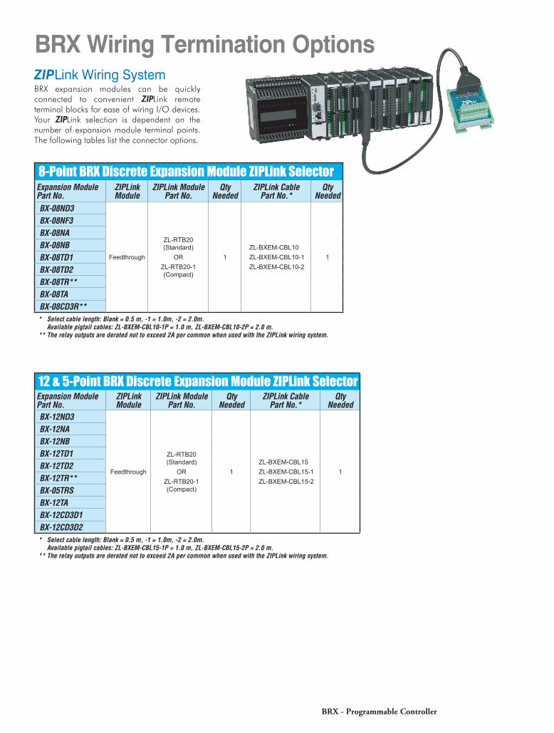
BRX Wiring Termination OptionsZIPLink Wiring SystemBRX expansion modules can be quickly connected to convenient ZIPLink remote terminal blocks for ease of wiring I/O devices. Your ZIPLink selection is dependent on the number of expansion module terminal points. The following tables list the connector options.
8-Point BRX Discrete Expansion Module ZIPLink SelectorExpansion Module Part No.
ZIPLink Module
ZIPLink Module Part No.
Qty Needed
ZIPLink Cable Part No.*
Qty Needed
BX-08ND3
Feedthrough
ZL-RTB20 (Standard)
ORZL-RTB20-1 (Compact)
1ZL-BXEM-CBL10ZL-BXEM-CBL10-1ZL-BXEM-CBL10-2
1
BX-08NF3BX-08NABX-08NBBX-08TD1BX-08TD2BX-08TR**BX-08TABX-08CD3R*** Select cable length: Blank = 0.5 m, -1 = 1.0m, -2 = 2.0m.
Available pigtail cables: ZL-BXEM-CBL10-1P = 1.0 m, ZL-BXEM-CBL10-2P = 2.0 m.** The relay outputs are derated not to exceed 2A per common when used with the ZIPLink wiring system.
12 & 5-Point BRX Discrete Expansion Module ZIPLink SelectorExpansion Module Part No.
ZIPLink Module
ZIPLink Module Part No.
Qty Needed
ZIPLink Cable Part No.*
Qty Needed
BX-12ND3
Feedthrough
ZL-RTB20 (Standard)
ORZL-RTB20-1 (Compact)
1ZL-BXEM-CBL15ZL-BXEM-CBL15-1ZL-BXEM-CBL15-2
1
BX-12NABX-12NBBX-12TD1BX-12TD2BX-12TR**BX-05TRSBX-12TABX-12CD3D1BX-12CD3D2* Select cable length: Blank = 0.5 m, -1 = 1.0m, -2 = 2.0m.
Available pigtail cables: ZL-BXEM-CBL15-1P = 1.0 m, ZL-BXEM-CBL15-2P = 2.0 m.** The relay outputs are derated not to exceed 2A per common when used with the ZIPLink wiring system.
BRX - Programmable Controller
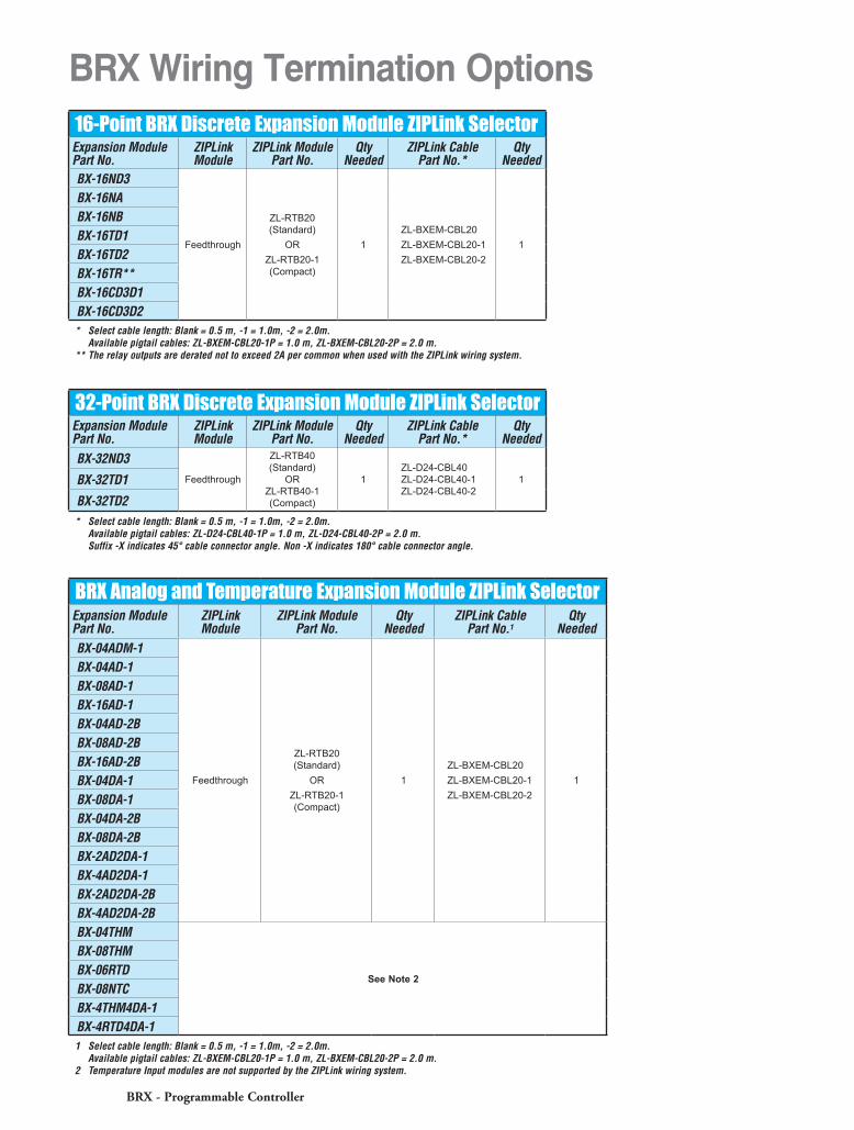
16-Point BRX Discrete Expansion Module ZIPLink SelectorExpansion Module Part No.
ZIPLink Module
ZIPLink Module Part No.
Qty Needed
ZIPLink Cable Part No.*
Qty Needed
BX-16ND3
Feedthrough
ZL-RTB20 (Standard)
ORZL-RTB20-1 (Compact)
1ZL-BXEM-CBL20ZL-BXEM-CBL20-1ZL-BXEM-CBL20-2
1
BX-16NABX-16NBBX-16TD1BX-16TD2BX-16TR**BX-16CD3D1BX-16CD3D2* Select cable length: Blank = 0.5 m, -1 = 1.0m, -2 = 2.0m.
Available pigtail cables: ZL-BXEM-CBL20-1P = 1.0 m, ZL-BXEM-CBL20-2P = 2.0 m.** The relay outputs are derated not to exceed 2A per common when used with the ZIPLink wiring system.
BRX Wiring Termination Options
BRX Analog and Temperature Expansion Module ZIPLink SelectorExpansion Module Part No.
ZIPLink Module
ZIPLink Module Part No.
Qty Needed
ZIPLink Cable Part No.1
Qty Needed
BX-04ADM-1
Feedthrough
ZL-RTB20 (Standard)
ORZL-RTB20-1 (Compact)
1ZL-BXEM-CBL20ZL-BXEM-CBL20-1ZL-BXEM-CBL20-2
1
BX-04AD-1BX-08AD-1BX-16AD-1BX-04AD-2BBX-08AD-2BBX-16AD-2BBX-04DA-1BX-08DA-1BX-04DA-2BBX-08DA-2BBX-2AD2DA-1BX-4AD2DA-1BX-2AD2DA-2BBX-4AD2DA-2BBX-04THM
See Note 2
BX-08THMBX-06RTDBX-08NTCBX-4THM4DA-1BX-4RTD4DA-11 Select cable length: Blank = 0.5 m, -1 = 1.0m, -2 = 2.0m.
Available pigtail cables: ZL-BXEM-CBL20-1P = 1.0 m, ZL-BXEM-CBL20-2P = 2.0 m.2 Temperature Input modules are not supported by the ZIPLink wiring system.
32-Point BRX Discrete Expansion Module ZIPLink SelectorExpansion Module Part No.
ZIPLink Module
ZIPLink Module Part No.
Qty Needed
ZIPLink Cable Part No.*
Qty Needed
BX-32ND3Feedthrough
ZL-RTB40 (Standard)
OR ZL-RTB40-1 (Compact)
1ZL-D24-CBL40 ZL-D24-CBL40-1 ZL-D24-CBL40-2
1BX-32TD1
BX-32TD2* Select cable length: Blank = 0.5 m, -1 = 1.0m, -2 = 2.0m.
Available pigtail cables: ZL-D24-CBL40-1P = 1.0 m, ZL-D24-CBL40-2P = 2.0 m. Suffix -X indicates 45° cable connector angle. Non -X indicates 180° cable connector angle.
BRX - Programmable Controller


![û6^BX]BX M±K - pku.edu.cn](https://img.pdfslide.us/doc/110x75/61736064a433c678797cd078/6bxbx-mk-pkueducn.jpg)