Embed Size (px)
Citation preview

OCT 171983
m.NUREG/CR-3223 EPRI NP-3093 GEAP-30157
BWR Refill-Reflood Program Final Report
Prepared by L. L. M yers
Nuclear Fuel and Special Projects Division ieneral Eioctric Company
» %
Prepared forU.S. Nuclear Regulatory Commission
andElectric Power Research institute
andGeneral Electric Company
CO okw- - I t •-\W\o
ftlSTHIBiltl'OiriJt THB BOdJMEUT IS UIILIMITEO
NO TIC E
This report was prepared as an account of work sponsored by an agency of the United States Government. Neither the United States Government nor any agency thereof, or any o f their employees, makes any warranty, expressed or implied, or assumes any legal liability of responsibility for any third party's use, or the results of such use, of any information, apparatus, product or process disclosed in this report, or represents that its use by such third party would not infringe privately owned rights.
U LOor o <C
oo
IIH
oo
Availability of Reference Materials Cited in NRC Publications
Most documents cited in NRC publications will be available from one of the following sources:
1. The NRC Public Document Room, 1717 H Street, N.W.Washington, DC 20555
2. The NRC/GPO Sales Program, U.S. Nuclear Regulatory Commission,Washington, DC 20555
3. The National Technical Information Service, Springfield, V A 22161
Although the listing that follows represents the majority of documents cited in NRC publications, it is not intended to be exhaustive.
Referenced documents available for inspection and copying for a fee from the NRC Public Document Room include NRC correspondence and internal NRC memoranda; NRC Office of Inspection and Enforcement bulletins, circulars, information notices, inspection and investigation notices; Licensee Event Reports; vendor reports and correspondence; Commission papers; and applicant and licensee documents and correspondence.
The following documents in the NUREG series are available for purchase from the NRC/GPO Sales Program: formal NRC staff and contractor reports, NRC-sponsored conference proceedings, and NRC booklets and brochures. Also available are Regulatory Guides, NRC regulations in the Code o f Federal Regulations, and Nuclear Regulatory Commission Issuances.
Documents available from the National Technical Information Service include NUREG series reports and technical reports prepared by other federal agencies and reports prepared by the Atomic Energy Commission, forerunner agency to the Nuclear Regulatory Commission.
Documents available from public and special technical libraries include ail open literature items, such as books, journal and periodical articles, and transactions. Federal Register notices, federal and state legislation, and congressional reports can usually be obtained from these libraries.
Documents such as theses, dissertations, foreign reports and translations, and non-NRC conference proceedings are available for purchase from the organization sponsoring the publication cited.
Single copies of NRC draft reports are available free upon written request to the Division of Technical Information and Document Control, U.S. Nuclear Regulatory Commission, Washington, DC 20555.
Copies of industry codes and standards used in a substantive manner in the NRC regulatory process are maintained at the NRC Library, 7920 Norfolk Avenue, Bethesda, Maryland, and are available there for reference use by the public. Codes and standards are usually copyrighted and may be purchased from the originating organization or, if they are American National Standards, from the American National Standards Institute. 1430 Broadway, New York, NY 10018.
GPO Printed copy price:
DISCLAIMER
This report was prepared as an account of work sponsored by an agency of the United States Government. Neither the United States Government nor any agency thereof, nor any of their employees, makes any warranty, express or implied, or assumes any legal liability or responsibility for the accuracy, completeness, or usefulness of any information, apparatus, product, or process disclosed, or represents that its use would not infringe privately owned rights. Reference herein to any specific commercial product, process, or service by trade name, trademark, manufacturer, or otherwise does not necessarily constitute or imply its endorsement, recommendation, or favoring by the United States Government or any agency thereof. The views and opinions of authors expressed herein do not necessarily state or reflect those of the United States Government or any agency thereof.
DISCLAIM ER
Portions of this document may be illegible in electronic image
products. Images are produced from the best available
original document.
NUREG/CR-3223 EPRI NP-3093 GEAP-30157 R2
BWR Refill-Reflood Program.Final Report nurfg/cr-3223
DE84 900 08G
Manuscript Completed; July 1983 Date Published: September 1983
Prepared by L. L. Myers
General Electric Company San Jose, CA 95125
Prepared forDivision of Accident Evaluation Office of Nuclear Regulatory Research U.S. Nuclear Regulatory Commission Washington, D.C. 20555 NRG FIN B5877
andElectric Power Research Institute 3412 Hillview Avenue Palo Alto, CA 94303
andNuclear Fuel and Special Projects Division General Electric Company San Jose, CA 95125
IS mm.

LEGAL NOTICE
This report was prepared by the General Electric Company as an account o l work sponsored by the Nuclear Regulatory Commission, the E lectric Power Research Institute, and the General E lectric Company. No person acting on behalf o f the NRC, the Institute, or members o f the Institute, or General Electric Company:
A. Makes any warranty o r representation, express or implied, with respect to the accuracy, completeness, or usefulness o f the inform ation contained in this report, or that information, apparatus, method or process disclosed in this report may not infringe privately owned rights, or
B. Assumes any liabilities with respect to the use of, o r fo r damages resulting from the use o f any information, apparatus, method or process disclosed in this report.
A B S T R A C T
The BWR Ref i l l -Ref lood Program is p a r t o f the cont inuing Loss o f Coolant
Accident (L O C A ) research in the Un i ted States which is jo int ly sponsored b y the
Nuclear Regula tory Commission, the Electr ic Power Research In s t i t u t e , and the
General E lectr ic Company. The c u r r e n t program expanded the focus o f this
research to include ful l scale exper imenta l evaluat ions o f mult idimensional and
mult ichannel effects d u r ing system re f i l l . The program has also made major
contr ibut ions to the BWR version o f the Trans ient Reactor Analysis Code ( T R A C )
which has been developed cooperatively with the Idaho National Eng ineer ing
Labora tory ( I NEL) fo r application to BWR t ran s ien ts .
A summary descr ipt ion of the complete program is p ro v ided including the
pr inc ipal f indings and main conclusions o f the p rogram . The results o f the
program have shown that mult idimensional and paral le l channel ef fects have the
potential to s igni f icant ly improve the system response o v e r that obse rved in single
channel tests. The best estimate models have been shown to p r o p e r l y model
physical phenomena and have the capab i l i ty to handle real ist ic BWR system
in teract ions. Suf f ic ient data are p resented to support the conclusions.
Hi/ )/!/

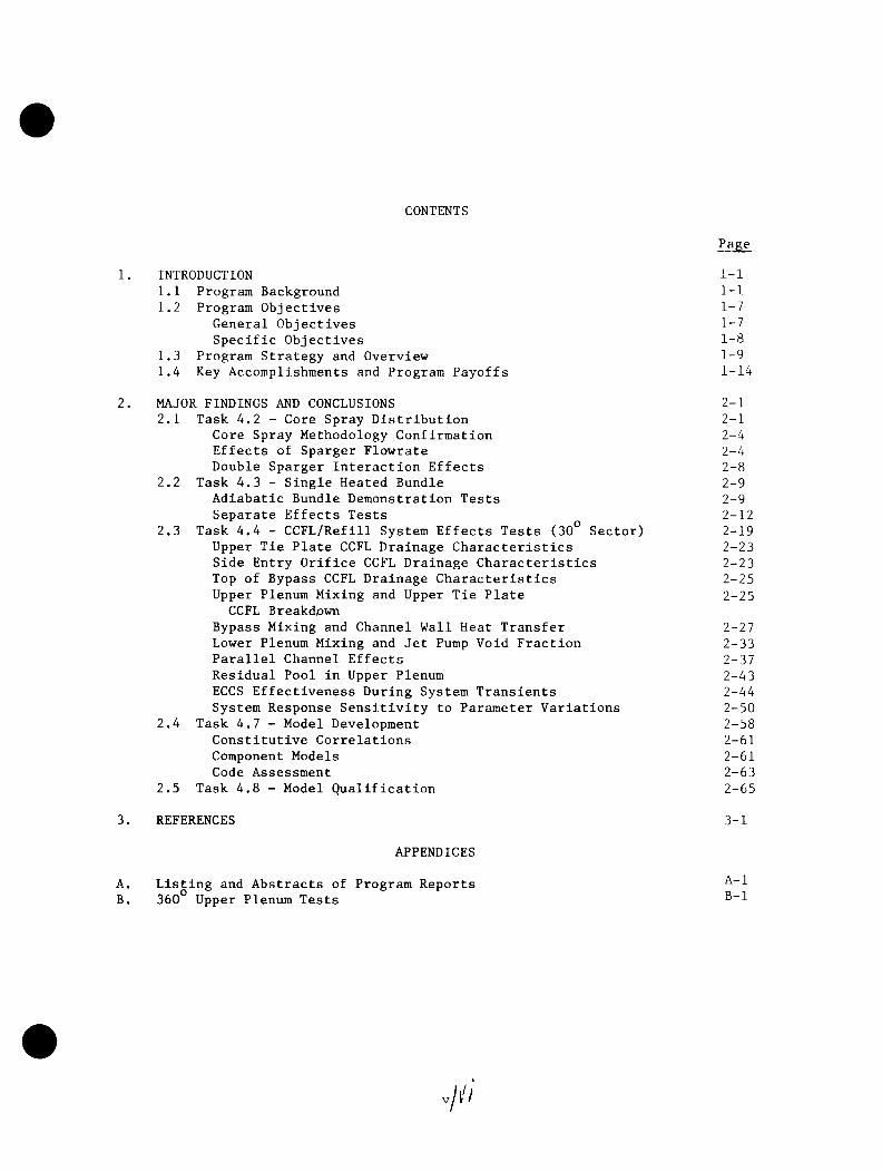
CONTENTS
Page
1. INTRODUCTION I-l1.1 Program Background I-l1.2 Program Objectives 1-7
General Objectives 1-7Specific Objectives 1-8
1.3 Program Strategy and Overview 1-91.4 Key Accomplishments and Program Payoffs 1-14
2. MAJOR FINDINGS AND CONGLUSIONS 2-12.1 Task 4.2 - Core Spray Distribution 2-1
Core Spray Methodology Confirmation 2-4Effects of Sparger Flowrate 2-4Double Sparger Interaction Effects 2-8
2.2 Task 4.3 - Single Heated Bundle 2-9Adiabatic Bundle Demonstration Tests 2-9Separate Effects Tests 2-12
2.3 Task 4.4 - CCFL/Refill System Effects Tests (30° Sector) 2-19Upper Tie Plate CCFL Drainage Characteristics 2-23Side Entry Orifice CCFL Drainage Characteristics 2-23Top of Bypass CCFL Drainage Characteristics 2-25Upper Plenum Mixing and Upper Tie Plate 2-25CCFL Breakdown
Bypass Mixing and Channel Wall Heat Transfer 2-27Lower Plenum Mixing and Jet Pump Void Fraction 2-33Parallel Channel Effects 2-37Residual Pool in Upper Plenum 2-43ECCS Effectiveness During System Transients 2-44System Response Sensitivity to Parameter Variations 2-50
2.4 Task 4.7 - Model Development 2-58Constitutive Correlations 2-61Component Models 2-61Code Assessment 2-63
2.5 Task 4.8 - Model Qualification 2-65
3. REFERENCES 3-1
APPENDICES
A. Listing and Abstracts of Program ReportsB. 360° Upper Plenum Tests


ILLUSTRATIONS
Figure Page
1.1-1 Relationship between Jointly Sponsored BWR Programs 1-1
1.1-2 Thirty-degree Steam Sector Test Facility 1-4
1.1-3 SSTF Bundle 1-5
1.1-4 BWR/6 Design Features 1-6
1.3-1 Program Element Integration 1-10
1.3-2 Program Implementation 1-11
1.4-1 Large Real Margin for BWR LOCA/ECCS 1-17
2.1-1 Core Spray Methodology 2-5
2.1-2 Comparison of Predicted Spray Distribution with 2-6Flow Measured in SSTF for Column 5 Bundles
2.1-3 Effect of Spray Flow Rate on Spray Distribution 2-7in SSTF (BWR/4-218)
2.1-4 Comparison of Superposition and Double Nozzle Spray 2-10Distributions for S3101 Nozzles for High Side Bundles
2.1-5 Comparsion of Superposition and Double Nozzle Spray 2-11Distributions for 1-inch VNC Nozzles for High SideBundles
2.2-1 Adiabatic Bundle Demonstration Tests 2-13
2.2-2 Adiabatic vs. Heated Bundle Refill-Reflood Collapsed 2-14Level Comparisons-Average Power/Average ECCS
2.2-3 Adiabatic vs. Heated Bundle Refill-Reflood Collapsed 2-15Level Comparisons - Low Power/Average ECCS/ 2.43-inchDiameter Side Entry Orifice
2.2-4 Adiabatic vs. Heated Bundle Refill-Reflood Collapsed 2-16Level Comparisons - Low Power/Average ECCS/ 1.257-inch Diameter Side Entry Orifice
2.2-5 Adiabatic vs. Heated Bundle Refill-Reflood Collapsed Level 2-17Comparisons - High Power/Average ECCS
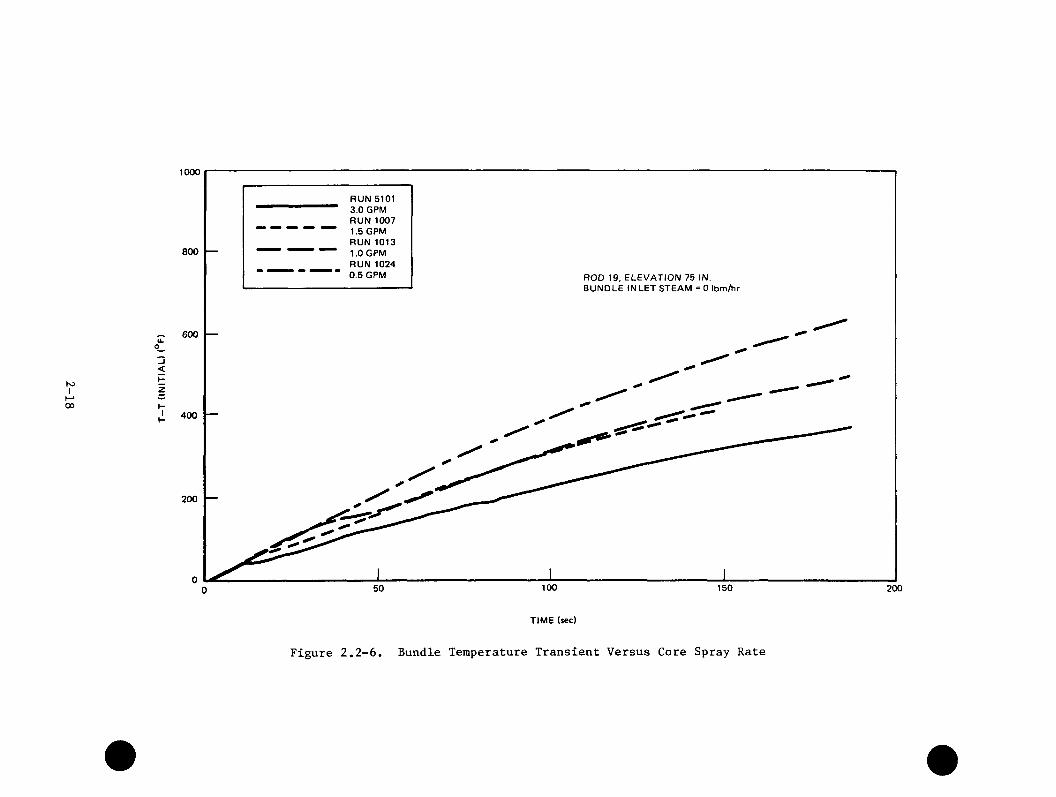
2.2-6 Bundle Temperature Transient vs. Core Spray Rate 2-18
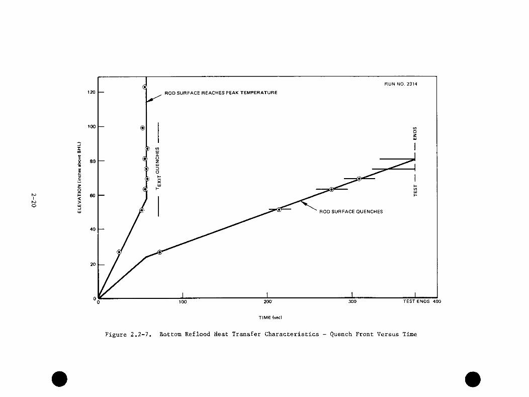
2.2-7 Bottom Reflood Heat Transfer Characteristics - Quench 2-20Front vs. Time
Vll

ILLUSTRATIONS (Continued)
Figure Page
2.2-8 Bottom Reflood Heat Transfer Characteristics - Typical 2-21Rod Temperatures
2.2-9 Bypass Heat Transfer Coefficient 2-22
2.3.1-1 Multi-Channel Upper Tie Plate CCFL 2-24
2.3.2-1 Multi-Channel Side Entry Orifice CCFL 2-26
2.3.4-1 Upper Plenum Mixing Test Results Showing Upper Plenum 2-28Response and Residual Pool
2.3.4-2 Upper Plenum Level and Subcooling with Two Core Sprays, 2-29One LPCI
2.3.4-3 Radial Distribution of Upper Tie Plate Subcooling with 2-30Two Core Sprays, One LPCI
2.3.5-1 Bypass Mixing and Heat Transfer 2-31
2.3.5-2 Bottom of Bypass Subcooling 2-32
2.3.6-1 Lower Plenum Mixing with LPCI Injected into Jet Pumps 2-34for BWR/4 ECCS Configuration
2.3.6-2 Lowe.t Plenum Subcooling for BWR/4 ECCS Configuration 2-35
2.3.6-3 Side Entry Orifice Subcooling for BWR/6 ECCS 2-36Configuration
2.3.6-4 SSTF Jet Pump Void Fraction and Impact on Refill-Reflood 2-38for BWR/6 ECCS Configuration
2.3.6-5 Lower Plenum Void Fraction - BWR/4 vs. BWR/6 ECCS 2-38Configuration
2.3.6-6 Region Refilling Response Comparisons - BWR/4 vs. BWR/6 2-40ECCS Configuration
2.3.7-1 Schematic of Multichannel Behavior Observed in 2-4130° SSTF
2.3.7-2 Typical Multi-Channel Conditions 2-42
2.3.8-1 Upper Plenum Pool Sensitivity to Spray Injection Elevation 2-45
2.3.8-2 Uniformity of Upper Plenum Pool 2-46
2.3.9-1 Regional Mass During 30° SSTF BWR/4 Large-Break ^LOCA Refill Test
viii
ILLUSTRATIONS (Continued)
Figure Page
2.3.9-2 Individual Bundle Mass and Level During 30° SSTF BWR/4
2.5-8 Comparison of Collapsed Liquid Level for the Countercurrent Flow Bundles
2-48Large-Break LOCA Refill Test
2.3.9-3 ECCS Effectiveness Demonstrated for BWR/6 2 - 4 9
2.3.9-4 Upper Plenum Liquid Continuous Region Demonstrated 2 - 5 1
2.3.10-1 Effect of ECCS Combinations 2 - 5 2
2.3.10-2 Effect of Single ECCS Operation 2 - 5 4
2.3.10-3 System Pressure Response for Different ECCS Combinations 2 - 5 5
2.3.10-4 System Pressure Histories for Variation of Initial 2 - 5 6System Mass
2.3.10-5 System Pressure Response for 1.0 DBA and 0.45 DBA 2 -5 7Break Areas
2.4-1 Vessel Void Fraction Distribution Comparison-PSTF 2 - 6 4
2.4-2 Cladding Temperature Response Comparison - THTF 2-66
2.4-3 Separator Performance Data Comparison 2 - 6 7
2.4-4 1/6-Scale Jet Pump Performance Data Comparison 2-68
2.4-5 System Response Comparisons-TLTA 2 - 6 9
2.4-6 Bundle Heat Transfer Comparisons - TLTA 2-70
2.5-1 Development/Assessment Process 2 - 7 4
2.5-2 Comparison of System Pressure 2 - 7 5
2.5-3 TRAC Calculation of Side Entry Orifice Vapor Velocities 2-76Showing Parallel Channel Transitions
2.5-4 Comparison of Lower Plenum Pressure Drop 2-77
2.5-5 Comparison of the Bypass Pressure Drop 2-78
2.5-6 Comparison of Upper Plenum Pressure Drop 2-79
2.5-7 Comparison of Upper Plenum Subcooling (Periphery) 2-802-81

TABLES
Table Page
1.4-1 Key Accomplishments 1-15
2.0-1 Capsule Summary of Major Findings and Conclusions 2-2
2.4-1 Major Improvements to TRAC and Their Principal Impact 2-60
2.5-1 Final Qualification Tests and Conclusions 2-72
2.5-2 Recommendations as a Result of TRACB02 Qualification 2-73
.ijpl

ACRONYM LIST
ADS Automatic Depressurization SystemANS American Nuclear SocietyASME American Society of Mechanical EngineersATLAS 17.2 MW Heat Transfer Loop (Facility located at GE in San Jose, CA,
for Thermal Hydraulic Testing of full-size BWR bundles)ATWS Anticipated Transient Without Scram
BBAF Beginning of Active FuelBD/ECC Blowdown Emergency Core Cooling ProgramBDHT Blowdown Heat Transfer ProgramBE Best EstimateBHL Beginning of Heated LengthBP Bypass RegionBT Boiling TransitionBWR Boiling Water ReactorBWR/R-R Boiling Water Reactor Refill-Reflood Program [Cooperatively
(NRC/EPRl/GE) funded program to understand and complete models for loss-of-coolant accident (LOCA)]
CCCFLCPCPRCRDCS
Counter-Current Flow Limiting Critical Path or Power Critical Power Ratio Control Rod Drive Core Spray
DDASDBADP
Data Acquisition System Design Basis Accident Differential Pressure
EECCSEG&GEHLEMEPRI
Emergency Core Cooling SystemCompany that manages INELEnd of Heated LengthEvaluation ModelsElectric Power Research Institute
FFIST
FW
Full Integral Simulation Test(GE facility located in San Jose, CA)
Feedwater
GGEGT
General Electric Company Guide Tube

ACRONYM LIST (Continued)
HHPCIHPCSHSF
HTC
High Pressure Coolant Injection High Pressure Core Spray Horizontal Spray Facility (GE facility located in San Jose, CA) Heat Transfer Coefficient
1INEL Idaho National Engineering Laboratory
JJAERlJP
Japan Atomic Energy Research Institute Jet Pump
LLABT Lynn Adiabatic Bundle TestLASL Los Alamos Scientific LaboratoryLOCA Loss-of-Coolant AccidentLP Lower PlenumLPCI Low Pressure Coolant InjectionLPCS Low Pressure Core SprayLTP Lower Tie Plate
MMCPR MPLHGR MS IV
Minimum Critical Power RatioMaximum Planar Linear Heat Generation RateMain Steam Isolation Valve
PPCTpsipsiapsigPWR
Peak Clad Temperature pounds per square inch pounds per square inch absolute pounds per square inch gauge Pressurized Water Reactor
RRCICR-R
RewetRHRRTDRTE
SSBASCRSEO
Reactor Core Isolation Cooling System Refill-RefloodRefill-(period of LOCA transient when the lower plenum is being refilled with liquid)
Reflood-(period of LOCA transient when the fuel region is being reflooded with liquid)
Quenching of a hot surface Residual Heat Removal Resistance Temperature Detector Responsible Test Engineer
Small Break Accident Silicon Controlled Rectifier Side Entry Orifice(located in fuel support casting to orifice bundle inlet flow)
ACRONYM LIST (Continued)
SHE Single Heated BundleSRV Safety Relief ValveSSTF Steam Sector Test Facility (30 degrees)
(Facility located at GE in Lynn, Mass., usedto study core spray distribution, upper plenum and system response for LOCA)
TTAF Top of Active FuelT/C ThermocoupleTHL Top of Heated LengthTLTA Two Loop Test ApparatusTMl Three Mile IslandTRAC Transient Reactor Analysis CodeTRACBDl BWR version of TRAC (B), Detailed Version (D), First Version (1)
UUPUTP
Upper Plenum Upper Tie Plate
VVSF Vallecitos Spray Facility (GE spray distribution facility located
near Livermore, CA)
YYTD Year-to-Date
ZZirc Zircaloy

PREVIOUS REPORTS IN BWR REFILL-REFLOOD SERIES
BWR Refill-Reflood Program Task 4.1 - Program Plan, G. W. Burnette, General Electric Company, NUREG/CR-1972, August 1981.
BWR Refill-Reflood Program Task 4.2 - Core Spray Distribution Experimental Task Plan, T. Eckert, General Electric Company, NUREG/CR-1558, November 1980.
BWR Refill-Reflood Program Task 4.2 - Core Spray Distribution Final Report, T. Eckert, General Electric Company, NUREC/CR-1707, March 1981.
BWR Refill-Reflood Program Task 4.3 - Single Heated Bundle Experimental Task Plan, D. D. Jones, L. L. Myers, J. A. Findlay, General Electric Company, NUREG/CR-1708, March 1981.
BWR Refill-Reflood Program Task 4.3 - Single Heated Bundle Experimental Task Plan, Addendum 1, Stage 3 - Separate Effects Bundle, D. D. Jones, General Electric Company, NUREG/CR-1708 - Add. 1, March 1981.
BWR Refill-Reflood Program Task 4.3 - Single Heated Bundle Final Report, W. A. Sutherland, J. E. Barton, J. A. Findlay, General Electric Company, NUREG/CR-2001, April 1983.
BWR Refill-Reflood Program Task 4.4 - CCFL/Refill System Effects Tests (30° Sector) - Experimental Task Plan, D. G. Schumacher, General Electric Company, NUREG/CR-1846, July 1981.
BWR Refill-Reflood Program Task 4.4 - CCFL/Refill System Effects Tests (30° Sector) - Experimental Task Plan, Addendum A, SSTF CCFL/Refill Shakedown Plan, D. G. Schumacher, T. Eckert, General Electric Company, NUREG/CR-1846, Add. A, September 1981.
BWR Refill-Reflood Program Task 4.4 - CCFL/Refill System Effects Tests (30° Sector) - Experimental Task Plan, Addendum B, 30° SSTF CCFL/Refill Separate Effect Test Plan, D. G. Schumacher, General Electric Company, NUREG/CR-1846, Add. B, September 1981.
BWR Refill-Reflood Program Task 4.4 - CCFL/Refill System Effects Tests (30° Sector) - Experimental Task Plan, Addendum C, 30° SSTF CCFL/Refill BWR/6 System Response Test Plan, D. G. Schumacher, General Electric Company, NUREG/CR-1846, Add. C, January 1982.
BWR Refill-Reflood Program Task 4.4 - CCFL/Refill System Effects Tests (30° Sector) - Experimental Task Plan, Addendum D, SSTF CCFL/Refill with ECCS Variation Test Plan (BWR/4 ECCS Geometry), D. G. Schumacher, General Electric Company, NUREG/CR-1846, Add. D, January 1982.
BWR Refill-Reflood Program Task 4.4 - 30° SSTF Description Document, J. E. Barton, D. G. Schumacher, J. A. Findlay, S. C. Caruso, General Electric Company, NUREG/CR-2133, May 1982.
BWR Refill-Reflood Program Task 4.4 - CCFL/Refill System Effects Tests (30° Sector) - Evaluation of Parallel Channel Phenomena, J. A. Findlay, General Electric Company, NUREG/CR-2566, November 1982.
BWR Refill-Reflood Program Task 4.4 - CCFL/Refill System Effects Tests (30° Sector) - SSTF System Response Test Results, D. G. Schumacher, T. Eckert, J. A. Findlay, General Electric Company, NUREG/CR-2568, April 1983.
xvii

BWR Refill/Reflood Program Task 4.4 - CCFL/Refill System Effects Tests (30° Sector) - Evaluation of ECCS Mixing Phenomena, J. A. Findlay, General Electric Company, NUREG/CR-2786, June 1983.
BWR Refill-Reflood Program Task 4.7 - Model Development Task Plan, J. G. M. Andersen, B. S. Shiralkar, General Electric Company, NUREG/CR-2057, September, 1981.
BWR Refill-Reflood Program Task 4.7 - TRAC/BWR Component Development, M. M. Aburomia, General Electric Company, NUREG/CR-2135, December 1981.
BWR Refill-Reflood Program Task 4.7 - Constitutive Correlations for Shear and Heat Transfer for the BWR Version of TRAC, J. G. M. Andersen, K. H. Chu, General Electric Company, NUREG/CR-2134, November 1982.
BWR Refill/Reflood Program Task 4.7 - Model Development: Basic Models for theBWR Version of TRAC, J. G. M. Andersen, K. H. Chu, J. C. Shaug, General Electric Company, NUREG/CR-2573, September 1983.
BWR Refill/Reflood Program Task 4.7 - Model Development: TRAC-BWR Component Models, Y. K. Cheung, V. Parameswaran, J. C. Shaug, General Electric Company, NUREG/CR-2574, September 1983.
BWR Refill-Reflood Program Task 4.8 - Model Qualification Task Plan, J. A. Findlay, G. L. Sozzi, General Electric Company, NUREG/CR-1899, August 1981.
BWR Refill/Reflood Program Task 4.8 - TRAC-BWR Model Qualification Final Report, Md. Alamgir, General Electric Company, NUREG/CR-2571, October 1983.
xviii

SUMMARY
The BWR Refill-Reflood Program is jointly sponsored by the U. S. Nuclear Regulatory Commission, the Electric Power Research Institute, and the General Electric Company. A large amount of Boiling Water Reactor (BWR) Loss—of-Coolant- Accident (LOCA) research in the United States has been carried out under this same joint sponsorship. While most of the previous programs have utilized essentially one-dimensional scaled simulations of the BWRj the current BWR Refill-Reflood program has expanded this focus to include full-scale experimental evaluations of multidimensional and multichannel effects during system refill. In addition, the program has experimentally investigated reflood heat transfer and distribution of ECC spray above the core. The program has also made major contributions to the BWR version of the Transient Reactor Analysis Code (TRAC) which has been developed cooperatively with the Idaho National Engineering Laboratory (INEL) for application to BWR transients.
Many of the investigations were performed in the Steam Sector Test Facility (SSTF), a full-scale model of a 30° sector of a BWR, using steam injection to simulate core heat. This system models the upper plenum and core regions closely, with all other regions simulated using the correct volume. This facility was used both for separate effects experiments to study multidimensional and multichannel phenomena and for simulation of late LOCA blowdown and refill in a large-scale facility.
The specific objectives of the BWR Refill-Reflood Program are: a) to developa better understanding of the phenomena controlling the refill and reflood phases of BWR LOCA's b) to provide a basis for, and support to, the development and qualification of best estimate BWR system thermal hydraulic codes for LOCA's, and c) to provide a basis for assessing assumptions used in establishing BWR LOCA safety margins.
It was recognized that the program goal of improved definition of BWR LOCA behavior could be met by either multiple complete full-scale demonstration experiments, or a judicious combination of realistic model development and appropriate supporting experiments. The latter approach was selected as the
S-1
strategy for this program. Specifically, this program Integrates new large-scale experiments with existing technology, current NRC code development, and new supporting model development to provide qualified realistic models to predict the entire BWR LOCA themal hydraulic transient. The new experiments of this program provided data for model development, model qualification, and for facility simulation qualification. The analytical effort provided phenomena and component models suitable for Incorporation Into the TRAC code and further provided assistance on BWR TRAC code formulation, qualification, and application.
The BWR Refill-Reflood Program has made a significant contribution to understanding BWR phenomena and to demonstrating the large safety margins that are present In BWR LOCA evaluations. The results from the extensive experimental studies have provided an excellent empirical understanding of LOCA response for the BWR.
ECC mixing and condensing effects noted In the separate effect and system transient tests were used to Identify upper plenum response phenomena. It was shown that upper plenum water flows freely Into the bypass region and that the bypass supplies subcooled water to the fuel channels. In addition, local subcooling In the upper plenum was found to break down CCFL at the upper tie plates of the peripheral bundles to allow the coolant to rapidly refill the lower plenum. Even with this drainage to the bypass and channels, a residual amount of water always remained In the upper plenum as a pool that distributes coolant to the top of all channels.
The results of the program have shown that multidimensional and parallel channel effects significantly Improve the system response over that observed In single channel tests. Of particular significance was the definition of three fuel bundle flow regimes and the resulting lower plenum response. Liquid downflow In the peripheral channels was found to be effective In speeding up the refill of the lower plenum. At the same time, cocurrent upflow In a few high power central bundles provided venting of steam produced by lower plenum flashing and resulted In effective heat transfer and more coolant retained within the shroud. Countercurrent flow was observed In the majority of the bundles with a two phase level resulting from CCFL at the side entry orifice. This type of flow, which Is characteristic of the single channel tests. Is effective In speeding channel reflood.
S-2
A principal payoff from the program is its contribution to the closure of BWR LOCA issues by demonstrating effective core cooling and providing the technology for greater confidence in calculation of LOCA consequences. BWR LOCA licensing uncertainties in the area of core spray distribution and reflood delay were eliminated as a result of separate effect and system transient tests at the SSTF. The system response tests clearly demonstrated the effectiveness of the ECC Systems in mitigating the effects of a break in the primary system. Corereflooding of all channels begins without delay upon initiation of the ECCSystems, and there is a residual pool of water in the upper plenum during this period which distributes coolant over the top of all channels. As a result, liquid can flow to the tops of the fuel channels regardless of the distribution of the spray over the tops of the channels. Thus, while spray distribution may be very important to current evaluation model calculations, the spray distribution is not important to the actual system response in jet pump plants (BWR/3 through 6).The rapid draining of liquid from the upper plenum into the peripheral bundles andbypass region also eliminated any reflood delay concerns.
The best estimate models have been shown to properly model physical phenomena and have the capability to handle realistic BWR system interactions. The combination of first principles modeling and an experimental basis that is diverse and complete enough to challenge the models, assures confident application to full scale reactors. TRAC is the primary method to provide a best estimate evaluation of BWR response and to quantify the margins in models used in the licensing of BWRs.
Comparison of design basis accident predictions from applying the best estimate model to the current BWR product (BWR/6) with the temperatures predicted using current licensing evaluation models for the same event have shown very large safety margins for the BWR. Also, as expected, the peak cladding temperatures for the BWR are slightly lower than those measured in the one-dimensional type experiments. Consistent with the large sector facility results, this advantage for the BWR stems from favorable multiple channel effects.
Results from the Refill-Reflood Program provide an extensive full scale, multi-channel, multi-dimensional data base of system performance under LOCA conditions. The data show the two-phase hydrodynamic parallel channel behavior that occurs in an array of multiple channels where there is a two-phase level in the lower plenum. The data show the regional mixing and steam condensation of subcooled ECCS water injected into the system. The effectivenss of the ECC
S-3

Systems and the beneficial effects of the multi-dimensional phenomena are demonstrated. The understanding of controlling phenomena that has been gained from this program has contributed substantially to the development of the BWR multi-dimensional best estimate analysis model, and the data base that has been obtained provides an important source for qualification of this model.
S-4
SECTION 1
INTRODUCTION
This program Is jointly sponsored by the Nuclear Regulatory Commission, the Electric Power Research Institute, and the General Electric Company. General Electric is the contracting organization responsible for performing the program work and reporting the results.
This document represents the final report to be issued under the program contract which has extended from May 1979 thru September 1983. The intent is to provide a summary description of the complete program including the principal findings of the program and the main conclusions and recommendations of the program. Sufficient data and analysis have been extracted from earlier reports to support the conclusions and recommendations. More detailed information concerning the work is contained in other program reports. A listing and abstract of all formal reports prepared under the program is included as Appendix A.
This section of the report provides a general discussion of the background, objectives, and strategy of the program, presents an overview of the various program tasks and concludes with a discussion of accomplishments of significance to the BWR. A more detailed discussion of the major findings and conclusions is provided in Section 2 for the respective tasks.
1.1 PROGRAM BACKGROUND
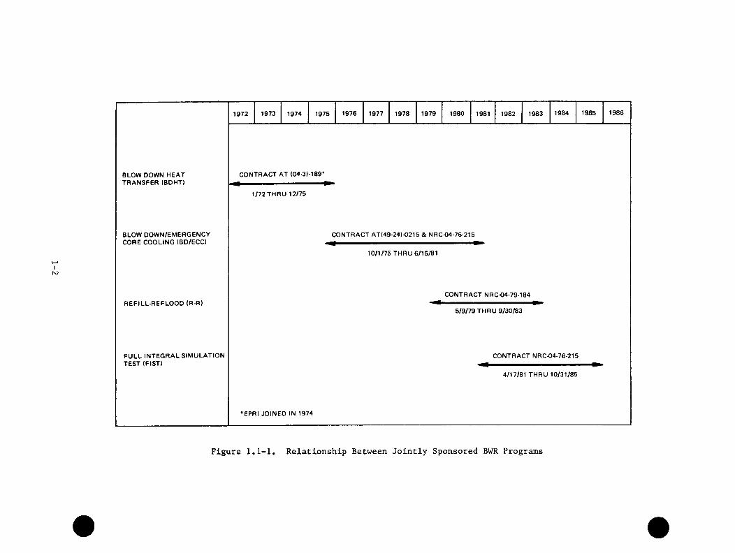
A large amount of Boiling Water Reactor (BWR) Loss-of-Coolant- Accident (LOCA) research in the United States has been jointly sponsored by the Nuclear Regulatory Commission (NRC), the Electric Power Research Institute (EPRI), and the General Electric Company (GE). The chronological relationship between four of these jointly sponsored programs including the BWR Refill-Reflood Program is shown in Figure 1.1-1.
The BWR Blowdown Heat Transfer Program (BDHT)^^^ investigated heat transfer and system response during the blowdown phase of the LOCA using the Two-Loop Test Apparatus (TLTA). The TLTA was a full-pressure scale model of a BWR using a single full-size, electrically simulated fuel bundle. It was originally scaled
1-1
IN5
BLOW DOWN HEAT TRANSFER (BDHT)
BLOW DOWN/EMERGENCY CORE COOLING (BD/ECC)
REFILL-REFLOOD (R-R)
FULL INTEGRAL SIMULATION TEST (FIST)
1972 1973 1974 1975 1976 1977 1978 1979 19B0 19B1 1982 1983 1984 1985 1986
CONTRACT AT (04-3)-189*
1/72 THRU 12/75
CONTRACT AT(49-24)-0215 & NRC-04-76-215
10/1/75 THRU 6/15/81
CONTRACT NRC-04-79-184
5/9/79 THRU 9/30/83
CONTRACT NRC-04-76-215
4/17/81 THRU 10/31/85
•EPRI JOINED IN 1974
Figure 1.1-1, Relationship Between Jointly Sponsored BWR Programs

from a BWR/4 system with a 7 X 7 fuel bundle. The tests investigated thermal- hydraulic response only through the blowdown phase and did not include the injection of simulated emergency core coolant (ECC).
This program was followed by the BWR Blowdown/ECC Program (BD/ECC). Earlyphases of this program used the TLTA to investigate the effect of BWR/6 scaling
(2)and an 8 X 8 simulated fuel bundle on the LOCA blowdown response . This workset the stage for tests of the complete large-break-LOCA transient, including the
(3)effect of ECC injection . Toward the end of this program, two small-break-(4)LOCA tests were also conducted as well as a core uncovery under slow loss of
coolant (boiloff) transient^^\
The continuing BWR Full Integral Simulation Test (FIST) has upgraded the TLTA to provide more realistic simulation of LOCA's from break initiation through reflood as well as simulation of transient events involving loss of inventory, multiple systems failures, and power t r a n s i e n t s T h e wide range of BWR transients which can be simulated in the FIST facility include power transients, small to intermediate break LOCAs, and other non-break transients.
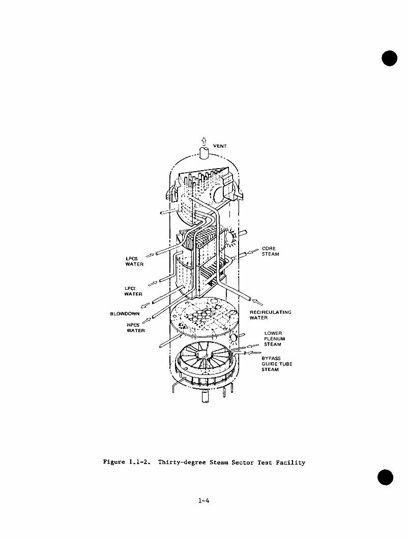
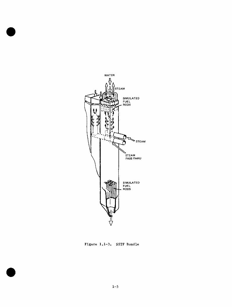
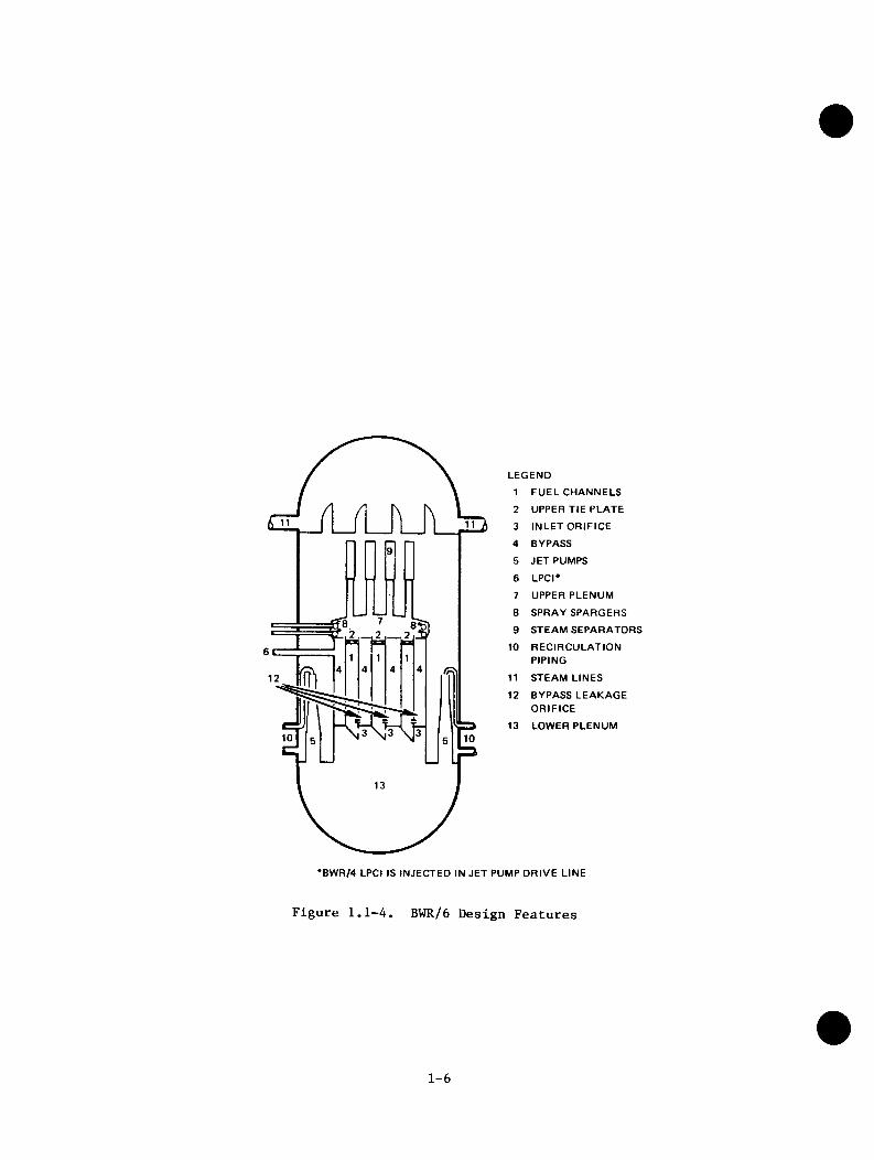
All of the above programs utilize essentially one-dimensional scaledsimulations of the BWR. The current BWR Refill-Reflood Program expanded thisfocus to include full scale experimental evaluations of multidimensional andmultichannel effects during system refill. In addition, the program hasexperimentally investigated reflood heat transfer and distribution of ECC sprayabove the core. Many of the investigations were performed in the Steam SectorTest Facility (SSTF), shown in Figure 1.1-2, a full-scale model of a 30° sector ofa BWR, using steam injection to simulate core heat. A schematic of the SSTFbundles is shown in Figure 1.1-3. This system models the upper plenum and coreregions closely, with all other regions simulated using the correct volume. Aschematic of the BWR regions is shown in Figure 1.1-4. The core-spray system andareas at the top and bottom of the core are duplicated exactly, using actualreactor hardware. This facility is used both for separate-effects experiments tostudy multidimensional and multichannel phenomena and for simulation of late LOCAblowdown and refill in a large-scale facility. The program has also made majorcontributions to the BWR version of the Transient Reactor Analysis Code (TRAC)which has been developed cooperatively with the Idaho National Engineering
il 8)Laboratory (INEL) for application to BWR transients ’
1-3
VENT
^ 5 . CORE , STEAM
LPCSWATER
r 2
LPCIWATER
RECIRCULATINGWATER
BLOWDOWN
HPCSWATER LOWER
PLENUMSTEAM
BYPASS GUIDE TUBE STEAM
Figure 1.1-2. Thirty-degree Steam Sector Test Facility
1-4
WATER
STEAM
SIMULATEDFUELRODS
STEAM
STEAM PASS THRU
SIMULATEDFUELRODS
Figure 1.1-3. SSTF Bundle
1-5
__2
10
LEGEND
1 FUEL CHANNELS
2 UPPER TIE PLATE
3 INLET ORIFICE
4 BYPASS
5 JET PUMPS
6 LP C r
7 UPPER PLENUM
8 SPRAY SPARGERS
9 STEAM SEPARATORS
10 RECIRCULATION PIPING
11 STEAM LINES
12 BYPASS LEAKAGE ORIFICE
13 LOWER PLENUM
•BWR/4 LPCI IS INJECTED IN JET PUMP DRIVE LINE
Figure 1.1-4. BWR/6 Design Features
1-6

This comprehensive research program represents a systematic effort to understand the BWR LOCA within appropriate research resources. The one-dimensional integral facilities with electrically heated rods are used for simulating the entire LOCA under ranges of temperatures and pressures typical of a BWR, Phenomena sensitive to scale size or multiple channels were investigated in the SSTF, which is large but lacks the high pressure and heated core (which could be prohibitively expensive at this large size). The experimental effort is closely related to the BWR TRAC calculational capability, which is used to bridge the gap among the experimental facilities and to extrapolate the results to a BWR.
1.2 PROGRAM OBJECTIVES
1.2.1 General Objectives
A major consideration in the design of engineered safety systems and licensing of Boiling Water Reactors (BWRs) is that sufficient Emergency Core Coolant (ECC) be provided to cool the reactor core, in the event of hypothetical* loss-of-coolant accidents (LOCAs). Historically, most limiting design basis LOCA calculations have been associated with postulated breaks or ruptures of recirculation loop coolant pipes, and have been treated according to three periods of system response known as the Blowdown, Refill, and Reflood phases. The BWR Blowdown Emergency Core Cooling (BWR BD/ECC) program addressed the blowdown and early ECC injection periods. The BWR Refill-Reflood program addresses the thermal-hydraulic behavior of most BWR plants (BWR 4 through 6) during the refill and reflood phases of postulated LOCAs on a generic basis. A central feature of these and related research efforts is the development and qualification of thermal hydraulic computer codes for realistic LOCA predictions of system and component behavior that are generally applicable to operating and planned BWR plants.
For jet pump plants (BWR 3 through BWR 6), the refill phase had been defined from the time that ECC systems are activated until sufficient coolant fills the lower plenum to initiate reactor core reflood from the core inlet. The reflood was defined to extend from the time that coolant reenters the core inlet until the core heatup transient is terminated, and the fuel rods are quenched. Recent experience with the Two-Loop Test Apparatus (TLTA) and the Single-Heated Bundle
*It is understood that this program is concerned with studying physical phenomena associated with reactor accidents that are estimated to have an extremely low probability of occurrence, and are therefore termed hypothetical.
1-7

(SHB) test facilities indicates that a core reflooding commences simultaneously with lower plenum refilling. This can occur because of the flow restriction at the core inlet. However, for ease of discussion, these two overlapping phases are often treated separately. Complex two-phase heat transfer and hydrodynamic phenomena would occur during these periods within reactor vessel regions (such as the reactor core, upper plenum, lower plenum, guide tubes, jet pumps, recirculation loop pipes, and downcomer annulus) as subcooled ECC interacts with steam, residual fluid, and hot internal surfaces. These phenomena could include:
a. Counter-current flow of steam and water at limiting locations (such as fuel bundle upper tie plates and spacer grids, core inlet orifices, top of the core bypass region, jet pump throats), which tend to restrict the downward penetration rate of liquid to the lower plenum.
b. Turbulent fluid mixing and condensation effectiveness, between the subcooled ECC and the residual fluid within vessel regions, that may enhance the downward penetration rate of liquid (this is caused by incomplete mixing).
c. Steam generation due to system depressurization and energy transfer from heated surfaces within internal regions of the vessel.
d. Evolution of fluid thermodjmamic states, phase distributions, and flow rates within and leaving the vessel.
e. Energy removal from the reactor core and vessel internals during the refill and reflood phases.
These phenomena would impact the core reflood timing, resultant peak clad temperatures, and the degree of cladding oxidation for a hypothetical BWR LOCA. Therefore, it was deemed appropriate to improve the definition of these phenomena and to develop more detailed experimental information and realistic modeling capability of the refill and reflood phases of hypothetical LOCAs in BWRs. Application of the information could result in future improved licensing models and safety analysis.
1.2.2 Specific Objectives
The specific objectives of the BWR Refill-Reflood Program are:
a. To develop a better understanding of the phenomena controlling the refill and reflood phases of BWR LOCAs'
b. To provide a basis for, and support to, the development and qualification of best estimate BWR system thermal hydraulic codes for LOCAs: and
c. To provide a basis for assessing assumptions used in establishing BWR LOCA safety margins.
1-8

1.3 PROGRAM STRATEGY AND OVERVIEW
It was recognized that the program goal of improved definition of BWR LOCA behavior could be met by either multiple complete full-scale demonstration experiments, or a judicious combination of realistic model development and appropriate supporting experiments. The latter approach was selected as the strategy for this program. Specifically, this program integrates new large-scale experiments with existing technology, current NRG code development, and new supporting model development to provide qualified realistic models to predict the entire BWR LOCA thermal hydraulic transient. The combination of these elements is illustrated in Figure 1.3-1. The strategy was successfully implemented by dividing the work into the nine tasks shown in Figure 1.3-2. The new experiments of this program provided data for model development, model qualification, and for facility simulation qualification. The analytical effort provided phenomena and component models suitable for incorporation into the TRAC code and further provided assistance on BWR TRAC code formulation, qualification, and application. In addition, the GE contribution of existing core spray distribution methodology was compared to the 30° Sector core spray data to guide decisions on further best-estimate core spray modeling requirements. However, because of the empirical basis for this methodology, it was not directly applicable for incorporation into TRAC. A brief overview of the role of each task follows. Complete reference information (including GE, NRG, and EPRl document numbers) and abstracts for the reports referred to are found in Appendix A.
1.3.1 Task 4.1-Program Plan
This task provided an initial focus for the program resources during the planning stages of the subsequent tasks. A Program Plan Report was prepared to elaborate on the means for meeting the stated program objectives. No further results are reported.
1.3.2 Task 4.2-Core Spray Distribution
This task provided core spray distribution data from steam environment tests to provide additional confirmation of existing methodology. An Experimental Task Plan Report was prepared to define the task and a Final Report was issued to document the applicability of the core spray methodology to the BWR/4&5-218 design.
1-9

L_
I------“ 1EXISTING
TECHNOLOGY^
ELEMENTS NOT INCLUDED IN THIS PROGRAM
SOME EXPERIMENTS FROM OUTSIDE THIS PROGRAM UTILIZED ALSO
FACILITYSIMULATION
OUALIFICATION
QUALIFICATIONEXPERIMENTS
MODELQUALIFICATION
TASK
QUALIFIED BWR BEST ESTIMATE THERMAL
HYDRAULIC METHODS
MODELDEVELOPMENT
TASK
DEVELOPMENTEXPERIMENTS^
CODES
Figure 1.3-1. Program Element Integration
1-10

TASK 4.1 PROGRAM
PLAN
PLANNING
EXPERIMENTAL
SUPPORT
ANALYTICAL
TASK 4.3 SINGLE HEATED BUNDLE
TASK 4.2 CORE SPRAY
DISTRIBUTION
TASK 4.6 TECHNICAL
SUPPORT
TASK 4.8 MODEL
QUALIFICATION
TASK 4.7 MODEL
DEVELOPMENT
TASK 4.4 CCFL/REFILL
SYSTEM EFFECTS
TASK 4.5 360° UPPER
PLENUM FACILITY
TASK 4.9 FINAL
REPORTDOCUMENTATION
Figure 1.3-2. Program Implementation
1-11

1.3.3 Task 4.3-Slngle Heated Bundle
This task confiraed the application of an adiabatic steam injection technique simulating vaporization in a heated bundle for use in the Steam Sector Test Facility (SSTF) and produced data to support model development. An Experimental Task Plan Report and Addendum were prepared to describe the testing necessary to achieve these two goals and a Final Report was issued to document the results.
1.3.A Task A.A-CCFL/Refill System Effects Tests (30° Sector)
This task provided data from a large-scale sector mockup of a BWR and identified and evaluated the phenomena controlling the system behavior during the refill phase of BWR LOCA's. This represented the major experimental task of the program. An Experimental Task Plan Report and four Addenda were prepared to define the approach, objectives, operating techniques, and test conditions necessary to accomplish the task objectives. The 30° Steam Sector Test Facility (SSTF) was the focal point of the task and an SSTF Description Document was prepared to describe the system. The results from this task are documented in three Topical Reports which address Parallel Channel Phenomena, System Response Test Results, and ECCS Mixing Phenomena, respectively.
1.3.5 Task A.5-360° Upper Plenum Facility
This task was originally intended to provide data for evaluating the effect of sector walls on CCFL breakdown and for qualifying the 30° SSTF. Early in the program (June 1981), observations from the SSTF testing indicated that radial mixing effects in the peripheral region dominate any circumferential or wall effects. Based on these observations and the axisymmetric upper plenum geometry and boundary conditions in the BWR, it was determined that the 30° sector simulation adequately captures upper plenum mixing effects and that there was no apparent reason to further investigate potential three-dimensional circumferential effects on the strong peripheral conditions which lead to subcooled CCFL breakdown. Activity on the task was terminated with only a conceptual design and preliminary size and scaling requirements for a 360° Upper Plenum test apparatus. A summary of this activity is presented in Appendix B. No further results are reported.
1-12
1.3.6 Tasks 4.6 - Technical Support
This task was originally intended as a general purpose task to provide technical support to the other tasks in the form of testing to assist in phenomena evaluation and measurement interpretation and state-of-the-art surveys of measurement and analysis techniques for possible adaptation and incorporation to augment the program. Early in the program (June 1981) it was determined that the studies were unnecessary, so the scope was reduced and the task was terminated. No results are reported.
1.3.7 Task 4.7 - Model Development
This task provided the models, correlations, and support necessary to develop a BWR version of the TRAC code. This represented the main analytical task of the program. A Task Plan Report was prepared to describe the major activities necessary to modify and adapt the TRAC code. A Component Development Report and a Constitutive Correlations Report were issued early in the program to document the models and correlations needed to realistically represent the components and phenomena which are unique to a BWR. Two topical reports were issued at the conclusion of the task. The first of these summarizes the Basic Models for the BWR Version of TRAC, discusses improvements in the basic equations and efficiency of the TRAC code and describes assessment activities. The second topical summarizes TRAC-BWR Component Models and assessment of these models. Furthermore, it describes a single channel model.
1.3.8 Task 4.8 - Model Qualification
This task assessed the capability of the TRAC-BWR code to provide realistic predictions of component and system behavior under BWR LOCA-ECCS conditions. A Task Plan Report was prepared to describe the plan for performing the assessments of the models and a Final Report was issued to document the final qualification of the best estimate BWR-LOCA model.
1.3.9 Task 4.9 - Final Report
This task provided coordination of the program tasks and development of the present Final Report, to provide a summary description of the entire program and the principal findings of the program.
1-13
1.4 KEY ACCOMPLISHMENTS AND PROGRAM PAYOFFS
The BWR Refill-Reflood Program has made a significant contribution to understanding BWR phenomena and to demonstrating the large safety margins that are present in BWR LOCA evaluations. Some of the key accomplishments of the program are summarized in Table 1.4-1. The results from the extensive experimental studies have provided an excellent empirical understanding of LOCA response for the BWR.
ECC mixing and condensing effects noted in the separate effect and system transient tests were used to identify upper plenum response phenomena. It was shown that upper plenum water flows freely into the bypass region and that the bypass supplies subcooled water to the fuel channels. In addition, local subcooling in the upper plenum was found to break down CCFL at the upper tie plates of the peripheral bundles to allow the coolant to rapidly refill the lower plenum. Even with this drainage to the bypass and channels, a residual amount of water always remained in the upper plenum as a pool that distributes coolant to the top of all channels.
The results of the program have shown that multidimensional and parallel channel effects significantly improve the system response over that observed in single channel tests. Of particular significance was the definition of three fuel bundle flow regimes and the resulting lower plenum response. Liquid downflow in the peripheral channels was found to be effective in speeding up the refill of the lower plenum. At the same time, co-current upflow in a few high power central bundles provided venting of steam produced by lower plenum flashing and resulted in effective heat transfer and more coolant retained within the shroud. Countercurrent flow was observed in the majority of the bundles with a two phase level resulting from CCFL at the side entry orifice. This type of flow, which is characteristic of the single channel tests, is effective in speeding channel reflood.
A principal payoff from the program is its contribution to the closure of BWR LOCA issues by demonstrating effective core cooling and providing the technology for greater confidence in calculation of LOCA consequences. BWR LOCA licensing uncertainties in the area of core spray distribution and reflood delay were eliminated as a result of separate effect and system transient tests at the SSTF. The system response tests clearly demonstrated the effectiveness of the ECC Systems in mitigating the effects of a break in the primary system. Core
1-14
Table 1.4-1
Key Accomplishments
Confirmed Core Spray Methodology for BWR/4 and 5
Developed and Confirmed Hardware for Sector System Tests
Provided Full Scale Three Dimensional Data
Demonstrated Effectiveness of Refill-Reflood Process
Developed Key Models for Best Estimate Code
Qualified Best Estimate Code with Data
1-15
reflooding of all channels begins without delay upon initiation of the ECC Systems, and there is a residual pool of water in the upper plenum during this period which distributes coolant over the top of all channels. As a result, liquid can flow to the tops of the fuel channels regardless of the distribution of the spray over the tops of the channels. Thus, while spray distribution may be very important to current evaluation model calculations, the spray distribution is not important to the actual system response in jet pump plants (BWR/3 through BWR/6). The rapid draining of liquid from the upper plenum into the peripheral bundles and bypass region also eliminated any reflood delay concerns.
The best estimate models have been shown to properly model physical phenomena and have the capability to handle realistic BWR system interactions. The combination of first principles modeling and an experimental basis that is diverse and complete enough to challenge the models, assures confident application to full scale reactors. TRAC is the primary method to provide a best estimate evaluation of BWR response and to quantify the margins in models used in the licensing of BWRs.
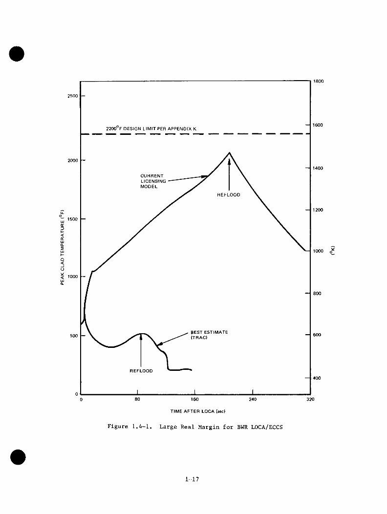
Representative results from applying the best estimate model to the current BWR product (BWR/6) are illustrated in Figure 1.4-1. These design basis accident predictions are compared with the temperatures predicted using current licensing evaluation models for the same event. As expected from the experimental results, very large safety margins are predicted for the BWR. Also, as expected, the peak cladding temperatures for the BWR are slightly lower than those measured in the one-dimensional type experiments. Consistent with the large sector facility results, this advantage for the BWR stems from favorable multiple channel effects.
1-16
1800
2500
16002200 F DESIGN LIM IT PER APPENDIX K
20001400
CURRENTLICENSINGMODEL
REFLOOD
1200u.o1500lUdD
I-<dUJCLSUJH 1000
o<_lo< 1000 mQ.
800
BEST ESTIMATE (TRAC) 600500
REFLOOD400
80 160 3202400
o
TIME AFTER LOCA (sec)
Figure l.A-1. Large Real Margin for BWR LOCA/ECCS
1-17

Section 2
MAJOR FINDINGS AND CONCLUSIONS
Each of the three experimental tasks and the two analytical tasks depicted in Figure 1.3-2 provided results which were significant to fulfilling the objectives of the BWR Refill-Reflood Program. A capsule summary of the major findings and conclusions for each of these tasks is provided in Table 2.0-1. The following subsections expand on these results for each pertinent task and provide support for the conclusions and recommendations. Detailed information and documentation can be found in the reports for the specific tasks which are listed and abstracted in Appendix A.
Results from the BWR Refill-Reflood Program provide an extensive full scale, multi-channel, multi-dimensional data base of system performance under LOCA conditions. The data show the two-phase hydrodynamic parallel channel behavior that occurs in an array of multiple channels when there is a two-phase level in the lower plenum. The data show also the regional mixing and steam condensation of subcooled ECCS water injected into the system. The effectiveness of the ECC Systems and the beneficial effects of the multi-dimensional phenomena are demonstrated. The understanding of controlling phenomena that has been gained from this program has contributed substantially to the development of the BWRmulti-dimensional best estimate analysis model, and the data base that has beenobtained provides an important source for qualification of this model.
2.1 TASK 4.2 - CORE SPRAY DISTRIBUTION
The overall objectives of Task 4.2 of the BWR Refill-Reflood Program were to (1) provide core spray distribution data from steam environment tests for best estimate model qualification; (2) provide additional confirmation of the existing methodology; and (3) identify any further model requirements. Core spraydistribution data for individual nozzles, and for arrays of nozzles, have beenobtained in both air and steam environments for use in model qualification. This data has provided additional confirmation of the existing core spray methodology. No further model requirements were identified as a result of these tests. The effects of sparger flow rate and sparger-to-sparger interaction on core spray distribution were also studied during this test program.
2-1

Table 2.0-1
CAPSULE SUMMARY OF MAJOR FINDINGS AND CONCLUSIONS
Task 4.2 - Core Spray Distribution
o Previously confirmed core spray methodology is applicable to BWR/4 and 5 - 218 design.
o Sparger-to-sparger interaction effects can be incorporated into themethodology by developing "nozzle pair" nozzle simulators.
o No further model requirements are identified.
Task 4.3 - Single Heated Bundle
o The appropriateness of using adiabatic steam injection to simulatebundle heat transfer vaporization in the Steam Sector Test Facility (SSTF) empirically demonstrated.
o Core spray heat transfer cooling capability increases linearly withspray flow over the range tested (0.5 to 3.0 gpm).
o Bottom reflooding of a heated bundle first limits the temperature riseof the rods and then quenches them starting at the bottom and progressing to the top with a well-defined quench front. The steady state heat transfer from the channel wall to a flooded bypass is characterized by an overall heat transfer coefficient of 100 to 200 Btu/hr sq. ft. F.
Task 4.4 - CCFL/Refill System Effects Tests (30° Sector)
o Inlet orifice CCFL causes prompt reflooding of the channels for all ECCScombinations.
o The refill-reflood transient has little sensitivity to variations ofparameters such as initial system mass, break area, and ECCS temperature.
o Subcooled ECC liquid causes rapid Upper Tie Plate (UTP) CCFL breakdownin peripheral bundles near the spray header resulting in rapid drainage of water to the lower plenum.
o A residual liquid pool builds up in the upper plenum as soon as spraycomes on. This effectively distributes liquid coolant to the top of all channels making spray distribution unimportant.
o Upper plenum liquid rapidly fills the bypass region to proyide significant channel cooling and early bundle filling through leakage paths.
o Three parallel channel flow regimes can occur simultaneously:
Most of the core is in the counter-current flow regime with slowly draining moisture levels maintained by CCFL at the SEO.
The peripheral channels tend to be in liquid downflow.
A few central channels are in co-current upflow venting lower plenum steam to the upper plenum.
2-2

Table 2.0-1
CAPSULE SUMMARY OF MAJOR FINDINGS AND CONCLUSIONS (Continued)
o Parallel channel effects result in better ECCS performance than observed in single channel tests:
- Upper plenum liquid rapidly reaches the lower plenum, reducing void fraction and minimizing resultant steam and water loss out the jet pumps.
Subcooling at the SEO does not lead to CCFL breakdown and channel draining. This is due to redistribution of lower plenum steam -to the channels.
o LPCI injection effectively fills and subcools the lower plenum to speedbottom reflooding of the core, particularly with BWR/4 injection into the jet pump.
o Subcooled LPCI injection into the bypass mixes radially toward the corecenter, cooling the channel walls and draining subcooled water into the channels in the process.
Task 4.7 - Model Development
o Basic models developed for all significant BWR LOCA phenomena.
o Component models developed for BWR-unique hardware.
o Numerical and integral system improvements provide a practical BestEstimate model for the BWR (TRACB02).
Task 4.8 - Model Qualification
o TRACB02 extensively tested against separate effects and systemresponse experiments.
o Code demonstrated to realistically predict governing phenomena and keyevents in simulated LOCA experiments.
o No major analytical model deficiency identified for LOCA applications.
2-3

The steam tests were performed In the Horizontal Spray Facility (HSF) in San Jose, California, and in the 30-degree SSTF in Lynn, Massachusetts. The simulator tests were performed in both the Vallecitos Spray Facility (VSF) at the Vallecitos Nuclear Center (VNC) and in the HSF.
2.1.1 Core Spray Methodology Confirmation
Prior to the current program, single nozzle tests performed in steam and air had shown different spray distributions between the two environments. A methodology incorporating air and steam testing was developed for predicting full core spray distributions in steam environment. The methodology which was confirmed with the BWR/6 design, is summarized in Figure 2.1-1.
The current test program has demonstrated that the methodology for designing core spray spargers is applicable to an alternate BWR configuration (i.e., BWR/4&5). This design has different core spray sparger locations and different nozzle types than the BWR/6 design. The core spray methodology was successfully confirmed by the spray distribution of the 30-degree sector of the BWR/4-218 lower sparger in steam comparing very well with predicted values over the region tested. The excellent comparisons further confirm the basic assumption of separability of hydrodynamic and condensation effects for the core spray design methodology. They demonstrate that the methodology is also applicable with changes in spray nozzle type and sparger location. This confirmation is to be expected since the important assumption of separability of thermodynamics (i.e., condensing) and hydrodynamic effects should not be affected by such changes. Figure 2.1-2 indicates the comparison between predicted and measured bundle flows.
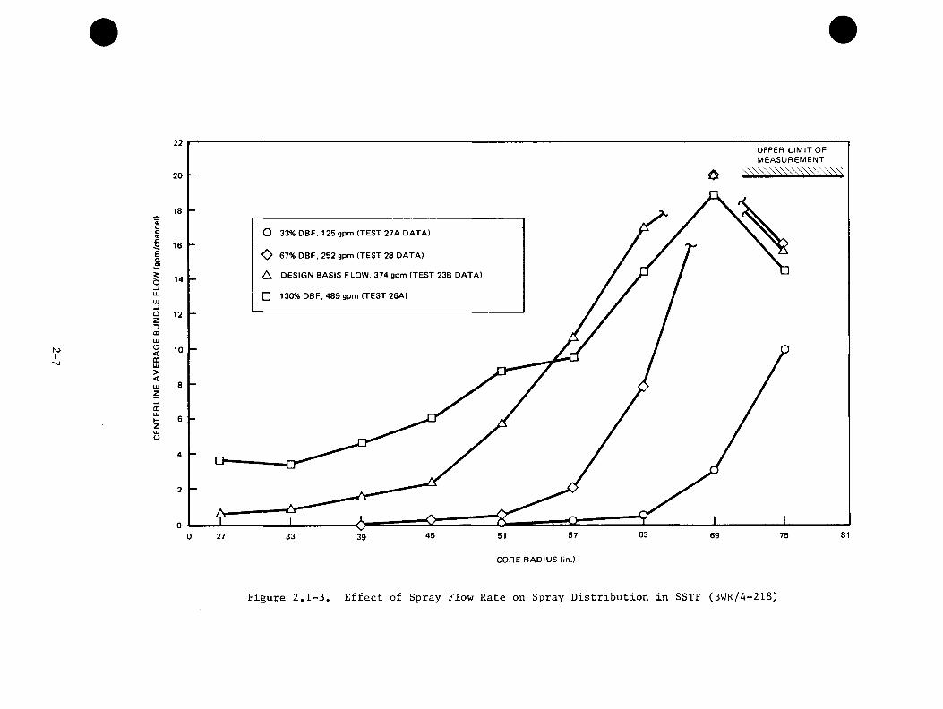
2.1.2 Effects of Sparger Flow Rate
The 30-degree sparger flow rate was varied to identify parameter effects. Increasing the flow rate of the lower sparger from the design basis flow to 130% of that flow greatly increases the spray density at 27-, 33-, 39-, 45-, and 51-inch radii. Conversely, reducing the flow to 33% and 67% of the design flow reduces the spray density in that region. These results are represented by Figure 2.1-3.
2-4

SINGLE NOZZLE TESTS IN STEAM,
REACTOR NOZZLES
DEVELOPSIMULATOR
NOZZLES
SINGLE NOZZLE TESTS IN AIR, SIMULATORS
GENUS, SUPERPOSITION OF SIMULATOR SINGLE NOZZLE
TEST DATA
GENUS, SUPERPOSITION
OF REACTOR SINGLE NOZZLE
TEST DATA
30-deg SECTOR TEST IN AIR, SIMULATORS
I 30-deg MIE j
A. REACTOR DESIGN NOZZLES ARE TESTED IN STEAM TO MEASURE THEIR SPRAY DISTRIBUTION
8. SIMULATOR NOZZLES ARE DEVELOPED TO HAVE SPRAY DISTRIBUTIONS IN AIR THAT ARE SIMILAR TO THEIR COUNTERPART REACTOR NOZZLES IN STEAM
C. GENUS IS A COMPUTER CODE WHICH CAN SUPERIMPOSE IN D IV ID U AL SPRAY DISTRIBUTIONS INTO ONE TOTAL SPRAY DISTRIBUTION
D. THE MULTIPLE-NOZZLE INTERACTION EFFECT (MIE) IS THE DIFFERENCE BETWEEN THE CALCULATED SUPERPOSITION RESULTS AND ACTUAL MULTIPLE NOZZLE TEST DATA
PRETEST PREDICTION FOR 30-deg REACTOR NOZZLES IN STEAM
30-deg SECTOR TEST IN STEAM,
REACTOR NOZZLES
METHODOLOGY IS CONFIRMED BY TEST RESULTS AGREEING WITH PREDICTION
Figure 2.1-1. Core Spray Methodology
2-5

hO1ON
26
UPPER LIM IT OF MEASUREMENTx \\\\\\\V \\\\\^
PREDICTION
TEST DATA (TEST 23BI20
Vcc(Q
§O_lu.
14
lijuOzDCOmZsDOo
33 3927 45 63 6951 57 75 81 87
CORE RADIUS (in.)
Figure 2.1-2, Comparison of Predicted Spray Distribution with Flow Measured in SSTF for Column 5 Bundles
NJI
22UPPER LIM IT OF MEASUREMENT
20
cc O 33% DBF, 125 gpm (TEST 27A DATA)
ea□) O 67% DBF, 252 gpm (TEST 28 DATA)
A DESIGN BASIS FLOW, 374 gpm (TEST 23B DATA)sOu.
14
□ 130% DBF. 489 gpm (TEST 26A)uuOzDflOUJO<cUi><UJZGCUJ»-ZUJU
6357 6945
CORE RADIUS (in.)
Figure 2.1-3. Effect of Spray Flow Rate on Spray Distribution in SSTF (BWR/4-218)

2.1.3 Double Sparger Interaction Effects
The nozzle placement configuration of the BWR/4&5 design is significantly different from that of the BWR/6, as illustrated below. Because of the closeness of the upper and lower sparger nozzles of the BWR/4&5 design, there was significant interest about sparger-to-sparger interaction effects.
BWR/4&5
d Q
BWR/6
Since there was no BWR/4 30-degree upper sparger installed at the SSTF, sparger-to-sparger interaction effects were investigated using a double sparger test assembly while the upper plenum and all of the 30-degree spargers were removed. As shown below, the BWR/4 & 5-218 design uses Spraco 3101 nozzles and 1-inch VNC nozzles on both the upper and lower spargers. Hence, the local interaction alternately involves pairs of Spraco 3101 nozzles and pairs of 1-inch VNC nozzles.
© £ J (cxdj\(@=Li\ a ± l_ ^
UPPER SPARGER
1 IN. VNC NOZZLE PAIR
^S3101 NOZZLE PAIR
LOWER SPARGER
2-8
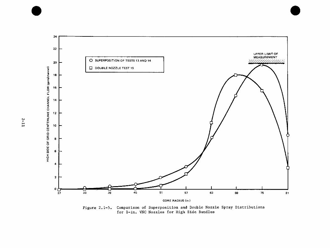
For each of the two types of nozzle pairs, nozzle-pair testing was performed at the SSTF wherein each nozzle was tested individually and then both nozzles of the pair were tested simultaneously. The two nozzles of the Spraco 3101 nozzle pair were found to have negligible effect on each other as shown in Figure 2.1-4. However, for the 1-inch VNC nozzle pair, the two sprays do interact significantly, as shown in Figure 2.1-5. Simultaneous operation shows an increase in flow at 69- and 63-inch core radii and a reduction in flow at 51- through 27-inch core radii when compared to the superposition of independent operation. The sparger-to-sparger interaction effects can be incorporated in an evaluation of two-sparger operation using the core spray methodology by developing "nozzle pair" nozzle simulators for full size distribution tests in air.
2.2 TASK 4.3 - SINGLE HEATED BUNDLE
The Single Heated Bundle (SHB) Task has provided test data:
a) To identify and evaluate system controlling phenomena during the refill-reflood phase of a postulated LOCA,
b) To support model development qualification,
c) To evaluate the application of the adiabatic steam injection techniquein the Steam Sector Test Facility (SSTF), and
d) To develop an adiabatic steam injection bundle design for use in theSSTF and develop a method for determining representative steam injection rates.
The Single Heated Bundle (SHB) Test Facility is a 1/624 volume scale mock-up of a BWR/6-218 reactor. The facility is designed to simulate the refill-reflood system response of a postulated loss of coolant accident (LOCA) and to obtainseparate effects test data under quasi-steady conditions.
2.2.1 Adiabatic Bundle Demonstration Tests
Adiabatic bundles, which use steam injection to simulate vaporization due to rod energy release, are used in the Steam Sector Test Facility (SSTF). The SHB facility accommodates either a full scale electrically heated rod bundle, or an adiabatic bundle as designed for the SSTF. The adiabatic bundle simulation adequacy was evaluated by performing duplicate system response tests in SHB, using the heated and steam injection bundles. The adiabatic steam injection rates for the SSTF are based upon the steam generation rate from the fuel rods for the BWR transient being simulated. The same technique was used in the SHB Task fordetermining the injection rates in the adiabatic bundle reference testsi
2-9

roI
24
22UPPER LIM IT OF MEASUREMENT
20
EaO) O SUPERPOSITION OF TESTS 16 AND 17
O-ju. □ DOUBLE NOZZLE TEST 18
UJZz<IoUJzcrUJKZu>o9QCOu.OLU9c/)X01
o U27 816957 63 7545 513933
CORE RADIUS (in.)
Figure 2.1-4. Comparison of Superposition and Double Nozzle Spray Distributionsfor S3101 Nozzles for High Side Bundles
K)I
24
22UPPER LIM IT OF MEASUREMENT
O SUPERPOSITION OF TESTS 13 AND 1420□ DOUBLE NOZZLE TEST 150)cc(B
£.u■?a3S 160 -I tk1 14 z<XozXUJHZUJoQXOu.Out0CO1 O X
°CT27 514539 57 6333 7569 81
CORE RADIUS (in.)
Figure 2.1-5. Comparison of Superposition and Double Nozzle Spray Distributionsfor 1-in. VNC Nozzles for High Side Bundles
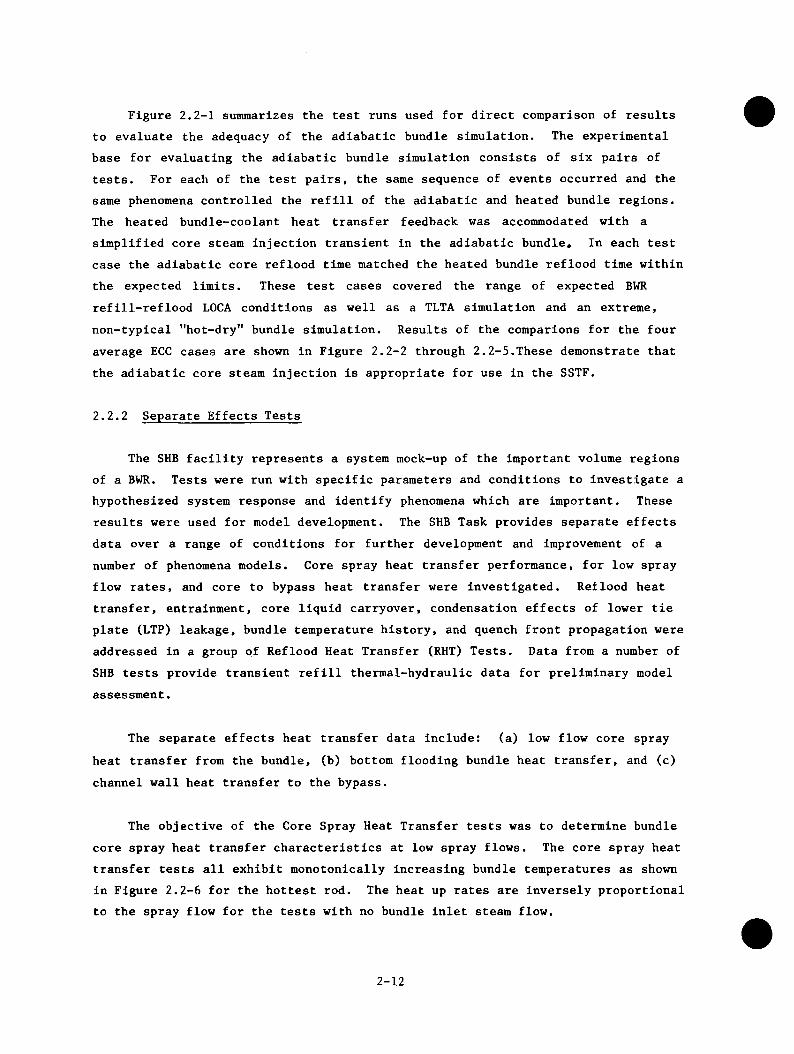
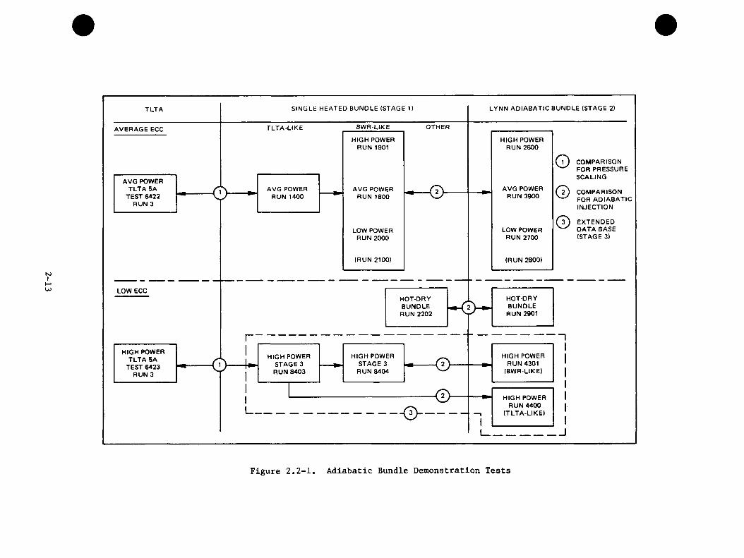
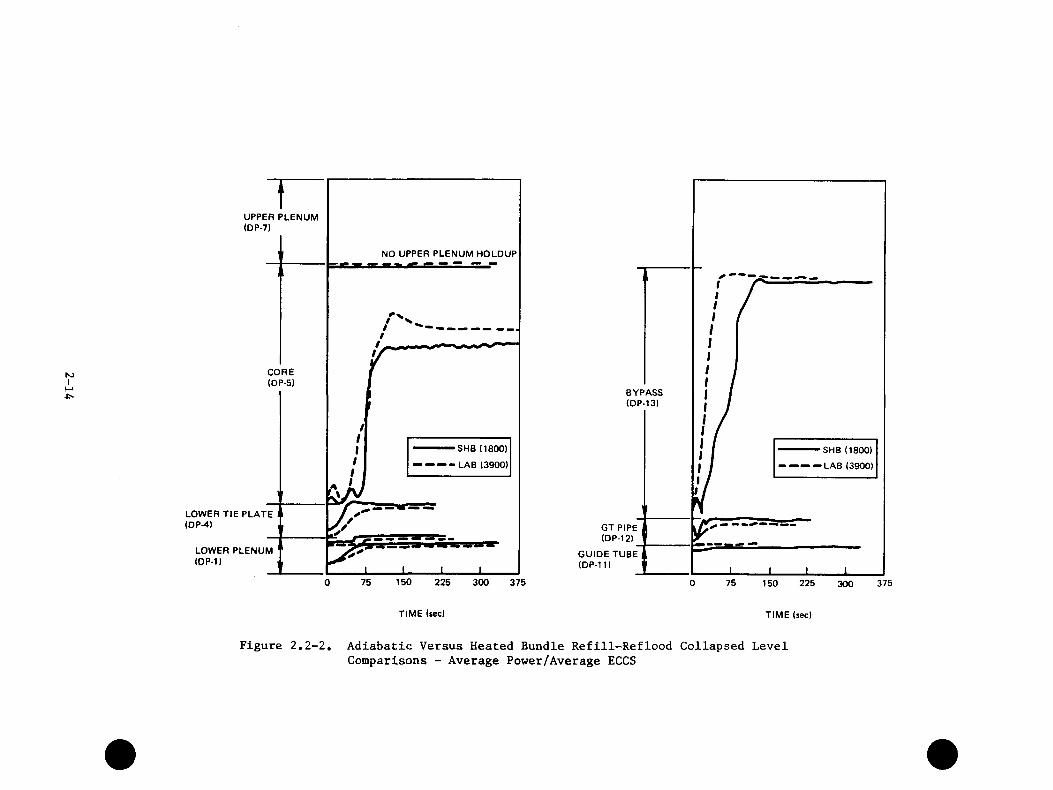
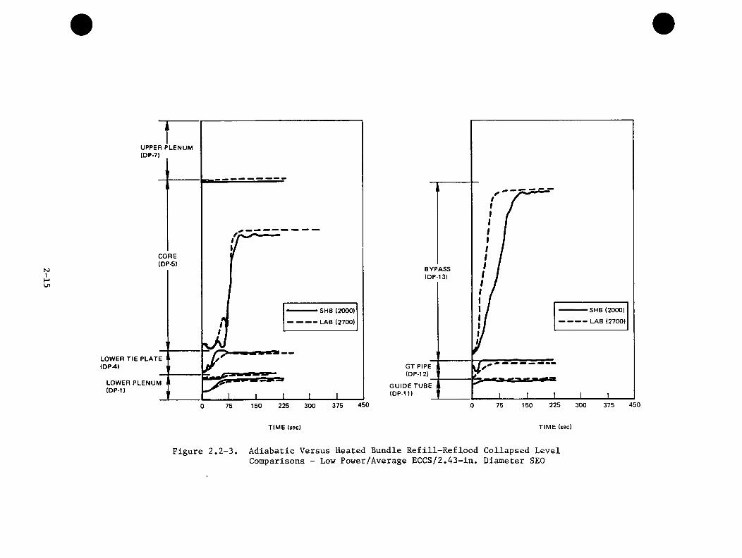
Figure 2.2-1 sunimarizes the test runs used for direct comparison of results to evaluate the adequacy of the adiabatic bundle simulation. The experimental base for evaluating the adiabatic bundle simulation consists of six pairs of tests. For each of the test pairs, the same sequence of events occurred and the same phenomena controlled the refill of the adiabatic and heated bundle regions. The heated bundle-coolant heat transfer feedback was accommodated with a simplified core steam injection transient in the adiabatic bundle. In each test case the adiabatic core reflood time matched the heated bundle reflood time within the expected limits. These test cases covered the range of expected BWR refill-reflood LOCA conditions as well as a TLTA simulation and an extreme, non-typical "hot-dry" bundle simulation. Results of the companions for the four average ECC cases are shown in Figure 2.2-2 through 2.2-5.These demonstrate that the adiabatic core steam injection is appropriate for use in the SSTF.
2.2.2 Separate Effects Tests
The SHB facility represents a system mock-up of the important volume regions of a BWR. Tests were run with specific parameters and conditions to investigate a hypothesized system response and identify phenomena which are important. These results were used for model development. The SHB Task provides separate effects data over a range of conditions for further development and improvement of a number of phenomena models. Core spray heat transfer performance, for low spray flow rates, and core to bypass heat transfer were investigated. Retlood heat transfer, entrainment, core liquid carryover, condensation effects of lower tie plate (LTP) leakage, bundle temperature history, and quench front propagation were addressed in a group of Reflood Heat Transfer (RHT) Tests. Data from a number of SHB tests provide transient refill thermal-hydraulic data for preliminary model assessment.
The separate effects heat transfer data include: (a) low flow core sprayheat transfer from the bundle, (b) bottom flooding bundle heat transfer, and (c) channel wall heat transfer to the bypass.
The objective of the Core Spray Heat Transfer tests was to determine bundle core spray heat transfer characteristics at low spray flows. The core spray heat transfer tests all exhibit monotonically increasing bundle temperatures as shown in Figure 2.2-6 for the hottest rod. The heat up rates are inversely proportional to the spray flow for the tests with no bundle inlet steam flow.
2-12
N3I
LYNN ADIABATIC BUNDLE (STAGE 2)SINGLE HEATED BUNDLE (STAGE 1)TLTA
OTHERAVERAGE ECCHIGH POWER
RUN 1901HIGH POWER
RUN 2600
COMPARISON FOR PRESSURE SCALING
AVG POWER TLTA 5A
TEST 6422 RUN 3
AVG POWER RUN 3900
AVG POWER RUN 1400
AVG POWER RUN 1800
COMPARISON FOR ADIABATIC INJECTION
EXTENDED DATA BASE (STAGE 3)
LOW POWER RUN 2700
LOW POWER RUN 2000
(RUN 2100) (RUN 28001
LOW ECCHOT-DRY BUNDLE RUN 2901
HOT-DRY BUNDLE
RUN 2202
HIGH POWER TLTA 5A
TEST 6423 RUN 3
HIGH POWER STAGE 3 RUN 8404
HIGH POWER RUN 4301
(BWR-LIKE)
HIGH POWER STAGE 3 RUN 8403
HIGH POWER RUN 4400
(TLTA-LIKE)
Figure 2.2-1. Adiabatic Bundle Demonstration Tests
NJI
UPPER PLENUM (DP-7)
CORE(DP-5)
LOWER TIE PLATE (DP-4)
LOWER PLENUM (DP-1)
NO UPPER PLENUM HOLDUP
SHB (1800)
- — — -L A B (3900)
I I75 150 225
TIME (sec)
300 375
BYPASS(DP-13)
SHB (1800)
LAB (3900)
GT PIPE (DP-12)
GUIDE TUBE (DP-11)
750 225 375150 300
TIME (sec)
Figure 2,2-2, Adiabatic Versus Heated Bundle Refill-Reflood Collapsed LevelComparisons - Average Power/Average ECCS
N3I
UPPER PLENUM (DP-7)
CORE(DP-5)
SHB (2000)
(JVB (2700)
LOWER TIE PLATE (DP-4)
LOWER PLENUM (DP-1)
450375150 225 300750
BYPASS(DP-13)
SHB (2000)
LAB (2700)
GT PIPE (DP-12)
GUIDE TUBE (DP-11)
450225150 300 3750 75
TIME (sec) TIM E (sec)
Figure 2.2-3. Adiabatic Versus Heated Bundle Refill-Reflood Collapsed LevelComparisons - Low Power/Average ECCS/2.43-in. Diameter SEO
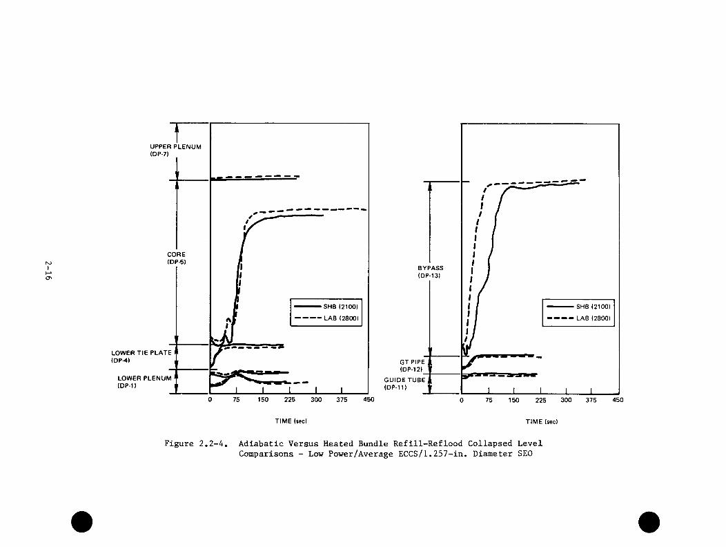
NJI
UPPER PLENUM (DP-7)
CORE(DP-5)
SHB (2100)
LAB (2800)
LOWER TIE PLATE (OP-4)
LOWER PLENUM (DP-1)
0 150 225 45075 300 375
BYPASS(DP-13)
SHB (2100)
LAB (2800)
GT PIPE (DP-12)
GUIDE TUBE (DP-11)
300 4500 75 150 375225
TIME (sec) TIME (sec)
Figure 2.2-4. Adiabatic Versus Heated Bundle Refill-Reflood Collapsed LevelComparisons - Low Power/Average ECCS/1.257-in. Diameter SEO
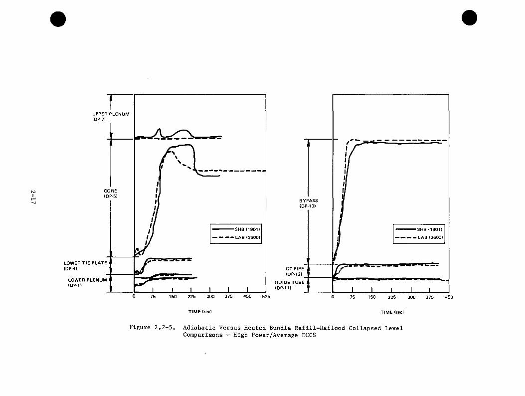
N)I
UPPER PLENUM (DP-7)
CORE(DP-5)
SHB (1901)
LAB (2600)
LOWER TIE PLATE (DP-4)
w wLOWER PLENUM (DP-1)
0 375 450300 52575 150 225
SHB (1901)
LAB (2600)
GT PIPE (DP-12)
GUIDE TUBE (DP-11)
0 15075 225 450300 375
TIM E (sec) TIME (sec)
Figure 2„2-5. Adiabatic Versus Heated Bundle Refill-Reflood Collapsed LevelComparisons - High Power/Average ECCS
1000
800 —
RUN 51013.0 GPM RUN 1007 1.5 GPM RUN 10131.0 GPM RUN 1024 0.5 GPM ROD 19, ELEVATION 75 IN.
BUNDLE INLET STEAM = 0 Ibm/hr
N3I
- 600 —
<ZI-
I1- 400 —
200 —
200
TIME (tec)
Figure 2.2-6. Bundle Temperature Transient Versus Core Spray Rate

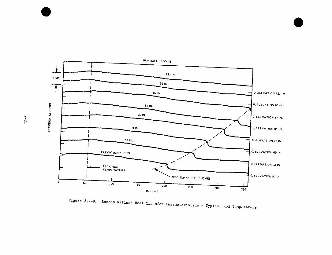
The objectives of the Reflood Heat Transfer tests was to determine core bottom flooding heat transfer characteristics. In a typical controlled bottom reflood heat transfer test the channel inlet steam flow was held constant and the inlet flooding rate was constant. The reflooding started cooling the bundle immediately, as the temperatures near the bottom reached their peak and startdecreasing. At approximately 50 seconds, the remaining upper two-thirds of thebundle temperatures peaked and also started decreasing. As the two-phase level continued to rise, the bottom of the rods started quenching. The quench front moved at a near constant rate of 0.15 in/sec up the bundle. Typical results are summarized in Figures 2.2-7 and 2.2-8. Similar responses were observed in the other reflooding tests.
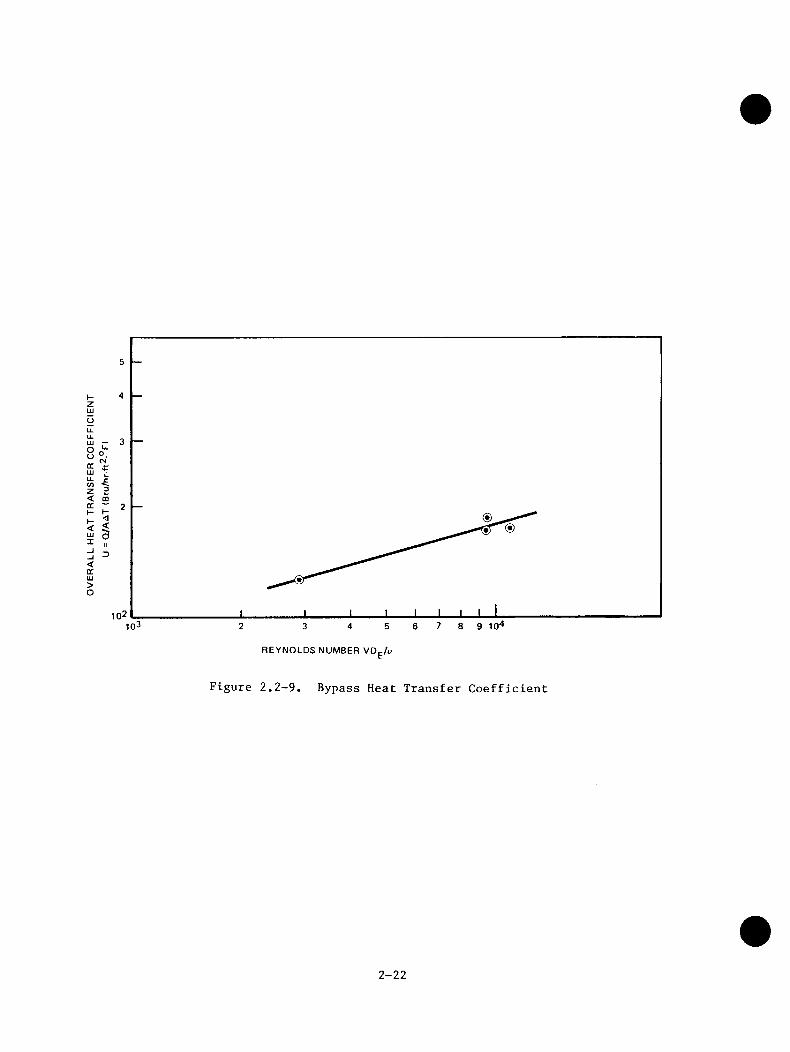
The objective of the Bypass Heat Transfer tests was to determine core to bypass heat transfer characteristics at different LPCI and core heat capacity rates. The steady state channel-to-bypass heat transfer tests give an overall heat transfer rate of 100 - 200 Btu/(hr-sq ft-deg F). These rates correspond to a full bypass with steady state liquid flow rate, and a channel at saturation temperature. The correlation of overall heat transfer coefficient, U, with Reynolds number is shown in Figure 2.2-9.
2.3 TASK 4.4 - CCFL/REFILL SYSTEM EFFECTS TESTS (30°SECTOR)
The objectives of the CCFL/Refill System Effects Tests were to provide data from a large-scale sector mockup of a BWR, and to identify and evaluate the phenomena controlling the system behavior during the refill phase of BWR LOCAs.
To provide this data base the existing Steam Sector Test Facility (SSTF), located in Lynn, Massachusetts, was upgraded to meet the requirements of transient LOCA simulation testing, and tests were performed to isolate key separate phenomena and to investigate BWR system refill/reflood during system blowdown.
The full scale 30-degree sector facility mocks up 58 individual fuel bundles, the surrounding peripheral and interstitial bypass region, upper and lower plenums, guide tubes, jet pump flow paths, downcomer, and ECCS injection systems. Being the only large test facility of this type, the information obtained from it is unique. Both separate effects tests, used to evaluate specific phenomena, and system response tests, used to evaluate system refill-reflood performance during blowdown transients, have been carried out.
2-19
tsjIhOO
RUN NO. 2314
120 ROD SURFACE REACHES PEAK TEMPERATURE
100
ICD9>>o9 80
9fCocZgH<>
60
UJ
ROD SURFACE QUENCHESUJ
40
20
TEST ENDS 400200 300100
TIME (sec)
Figure 2.2-7. Bottom Reflood Heat Transfer Characteristics - Quench Front Versus Time
roIN)
RUN 2314 ROD 46
123 IN.1000
95 IN.
0, e l e v a t io n 123 IN.
0, e l e v a t io n 95 IN.81 IN.
75 IN.0, e l e v a t io n 87 IN.
69 IN. 0, ELEVATION 81 IN.
0, ELEVATION 75 IN.63 IN.
0, ELEVATION 69 IN.e l e v a t io n = 51 IN.
0. e l e v a t io n 63 IN.PEAK RODt e m p e r a t u r e
0, e l e v a t io n 51 IN.ROD SURFACE QUENCHES
SO 100 150 200 250 300 350TIME (sec)
Figure 2.2-8. Bottom Reflood Heat TransferCharacteristics - Typical Rod Temperature
ID —O ' oQC LU
<a.< S.LU OX 7
<cc>o
5
4
3
2
6 7 8 9 10^2 3 4 5
REYNOLDS NUMBER VD^/u
Figure 2.2-9. Bypass Heat Transfer Coefficient
2-22
The separate effects tests included steady state tests of counter-current flow limiting (CCFL) at various locations and mixing of ECC fluid with steam and water in various regions. The system transients were experimental simulations of the later phases of the LOCA blowdown from 150 psia with core heat simulated by steam injection. The following topics are discussed individually and supporting data is presented:
12345678 9
10
Upper Tie Plate CCFL Drainage CharacteristicsSide Entry Orifice CCFL Drainage CharacteristicsTop of Bypass CCFL Drainage CharacteristicsUpper Plenum Mixing and Upper Tie Plate CCFL BreakdownBypass Mixing and Channel Wall Heat TransferLower Plenum Mixing and Jet Pump Void FractionParallel Channel EffectsResidual Pool in Upper PlenumECCS Effectiveness During System TransientsSystem Response Sensitivity to Parameter Variations
2.3.1 Upper Tie Plate CCFL Drainage Characteristics
The CCFL drainage characteristics of the bundle upper tie plates was measured over a range of core steam upflows. The flow path through the bypass was blocked by flooding this region with the LPCI. As shown in Figure 2.3.1-1, it was found that when the channels were isolated at the inlet by a high plenum water level, total upper tie plate CCFL drainage followed a prediction made from single channel characteristics. However, with the inlet orifices uncovered, allowing steam redistribution through the lower plenum, the drainage was greater then predicted due to parallel channel effects discussed later.
2.3.2 Side Entry Orifice CCFL Drainage Characteristics
These tests were performed by fixing the flow of saturated liquid to the channels and then increasing the steam flow to the lower plenum. The lower plenum level was kept below the SEO's so that the lower plenum steam could communicate freely among the channel inlets. When the SEO CCFL limit is exceeded, water starts collecting in the channels. Below this limit the channels remain empty.
2-23

<z<ocQ93a
O CHANNEL INTERACTION THROUGH LOWER PLENUM
SINGLE CHANNEL PREDICTION
A CHANNELS ISOLATED
LIQUID AVAILABLE TO UPPER PLENUM
CORE STEAM UPDRAFT
RECIR.
UPPER TIE PLATES
TOP OF BYPASS
LPCI
CORE STEAM
LEVEL ISOLATING CHANNELS
LEVEL ALLOWING CHANNEL INTERACTION
LOWERPLENUM
Figure 2.3.1-1, Multi-Channel Upper Tie Plate CCFL
2-2A
The lower plenum CCFL steam rate was predicted by calculating the drainage rate through each SEO. The SEO CCFL steam upflow rate for each channel was determined from its drainage rate and side entry orifice area using a SEO CCFL correlation based on single channel data. The sum of these steam rates is the total SEO CCFL steam flow, shown in Figure 2.3.2-1. The predicted SEO CCFL total steam rate is 3400 (lb/hr) for the liquid drainage rate tested. At the 3000 (lb/hr) test point the channels remained empty. At 3800 (lb/hr) they started filling. Thus the test responses are consistent with the predictions.
2.3.3 Top of Bypass CCFL Drainage Characteristics
Tests of CCFL at the top of the core bypass area were conducted by injecting steam between the channel boxes (to simulate steam from flashing) and measuring the amount of liquid draining between the channel boxes. During these tests it was not possible to limit the flow of liquid from the upper plenum down between the channel boxes, even for several times the amount of steam required to limit flow based on a simple one-dimensional calculation. This indicates that significant three-dimensional redistribution of flow occurred at this large scale, making the one-dimensional CCFL calculation for the core bypass area too conservative. This finding is significant in view of single channel results showing that flow of liquid through the leakage paths, from the core bypass area to the bundle is an effective reflooding mechanism. Thus, even for plants that do not have ECC injection in the core bypass area (i.e., BWR/3 and BWR/4) ECC can easily enter the core bypass area from the upper plenum and refill the bundle through the leakage paths.
2.3.4 Upper Plenum Mixing and Upper Tie Plate CCFL Breakdown
Upper plenum mixing tests were performed to investigate the mixing of the subcooled ECC spray with a two-phase mixture in the upper plenum and the process by which liquid penetrates down through the fuel channels. These separate effect tests differed from spray distribution tests in that sufficient steam was flowing up through the fuel channels to limit flow of liquid into the channels. Thus liquid could accumulate in the upper plenum. These tests were also conducted with the bypass full of liquid since, as indicated previously, liquid easily penetrates the bypass and it is impossible to accumulate a significant amount of liquid in the upper plenum until the bypass is filled. The objective of these tests was to investigate how long it takes the core spray to subcool a saturated mixture in the upper plenum sufficiently to cause subcooled CCFL breakdown at the top of the fuel channels.
2-25
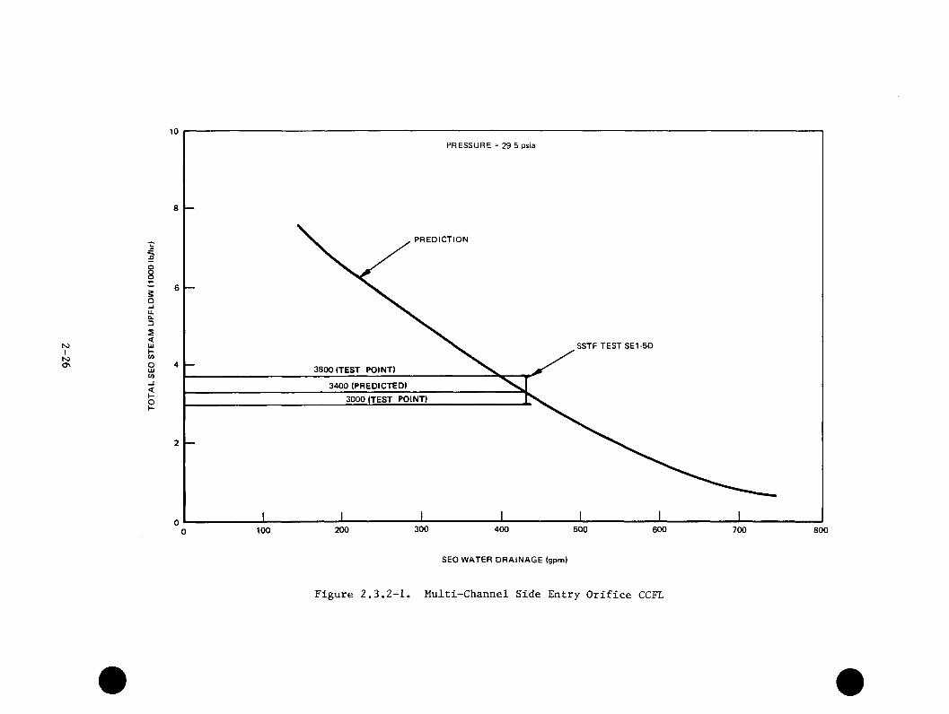
IS)IN)OS
OOo2o-Iu.0.3s<U)f—<nO
<h-oI-
10
PRESSURE = 29.5 psia
8
PREDICTION
6
SSTF TEST SE1-5D
4 3800 (TEST POINT)
3400 (PREDICTED)
3000 (TEST POINT)
2
0300 400 500 600200 700100 800
SEO WATER DRAINAGE (gpm)
Figure 2.3.2-1. Multi-Channel Side Entry Orifice CCFL

It was determined that, when the spray header was covered by a liquid pool or two-phase mixture, the ECC spray rapidly subcooled the pool in a localized areanear the spray headers. This is illustrated in Figure 2.3.4-1 which shows thattemperatures below the upper tie plates of peripheral bundles (near the sprayheader) were subcooled immediately after initiation of ECC spray. Other bundlesaway from the spray header showed no evidence of subcooling. This localized subcooling above the peripheral bundles caused subcooled breakdown of CCFL at the tops of these bundles and allowed upper plenum liquid to rapidly drain down the peripheral bundles. During tests with only one spray header operation, the drainage exceeds the injection rate and the upper plenum almost completely drained. The majority of the tests, however, resulted in draining only to the level of the spray header. This remaining level is discussed further in the Section 2.3.8.
The system response tests exhibited similar upper plenum subcooled mixing and UTP CCFL breakdown response as seen in the separate effects tests. The subcooling in the peripheral region and the upper plenum level increase together as shown in Figure 2.3.4-2. The radial concentration of subcooling near the periphery, as indicated in Figure 2.3.4-3, is also similar to that observed in separate effects tests.
2.3.5 Bypass Mixing and Channel Wall Heat Transfer
Bypass mixing tests were performed to investigate the mixing characteristics of subcooled LPCI flow injected into the bypass as in the BWR/6 design. Figure2.3.5-1 depicts these separate effects tests and includes characteristic contours of subcooling distribution throughout the bypass region. In each test, all of the steam Injected into the guide tube/bypass was condensed and the bottom of the bypass became subcooled. The total heat transferred to the LPCI water far exceeded the guide tube/bypass heat injection, demonstrating that heat transfer from the channels to the bypass is quite large. This is especially true in the peripheral region.
In the system response tests, the subcooling of the LPCI water again condensed all steam flowing up from the guide tubes. Figure 2.3.5-2 shows the largest subcooling existed at the periphery, with subcooling initially reaching the center of core within about 40 seconds. This is comparable to the bypass subcooling time measured in the separate effect tests.
2-27
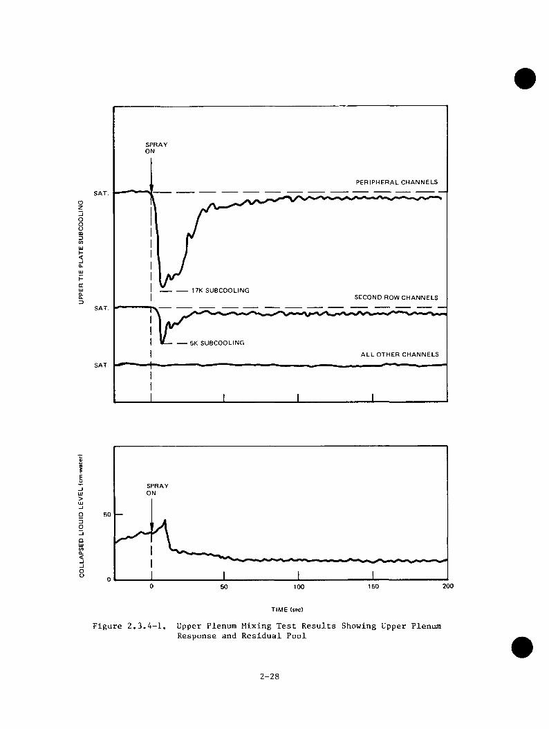
oz
oou
I-<
Hcc
SPRAYON
PERIPHERAL CHANNELS
SAT.
----------------17K SUBCOOLINGSECOND ROW CHANNELS
SAT.
ALL OTHER CHANNELS
SAT
>UJ
QUJCOQ.<OCJ
SPRAYON
50
2000 15050 100
TIME (sec)
Figure 2.3.4-1. Upper Plenum Mixing Test Results Showing Upper Plenum Response and Residual Pool
2-28
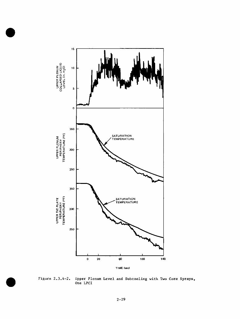
Ui
a.0.D
-I
350
SATURATIONTEMPERATURE>- UJ
OC QC
15 300LU LU
250
350
SATURATIONTEMPERATURE> LUOC oc
UJ ”1I B 300 5: <OC ccLU LU
250
1401000 20
TIME (sec)
Figure 2.3.4-2. Upper Plenum Level and Subcooling with Two Core Sprays, One LPCI
2-29
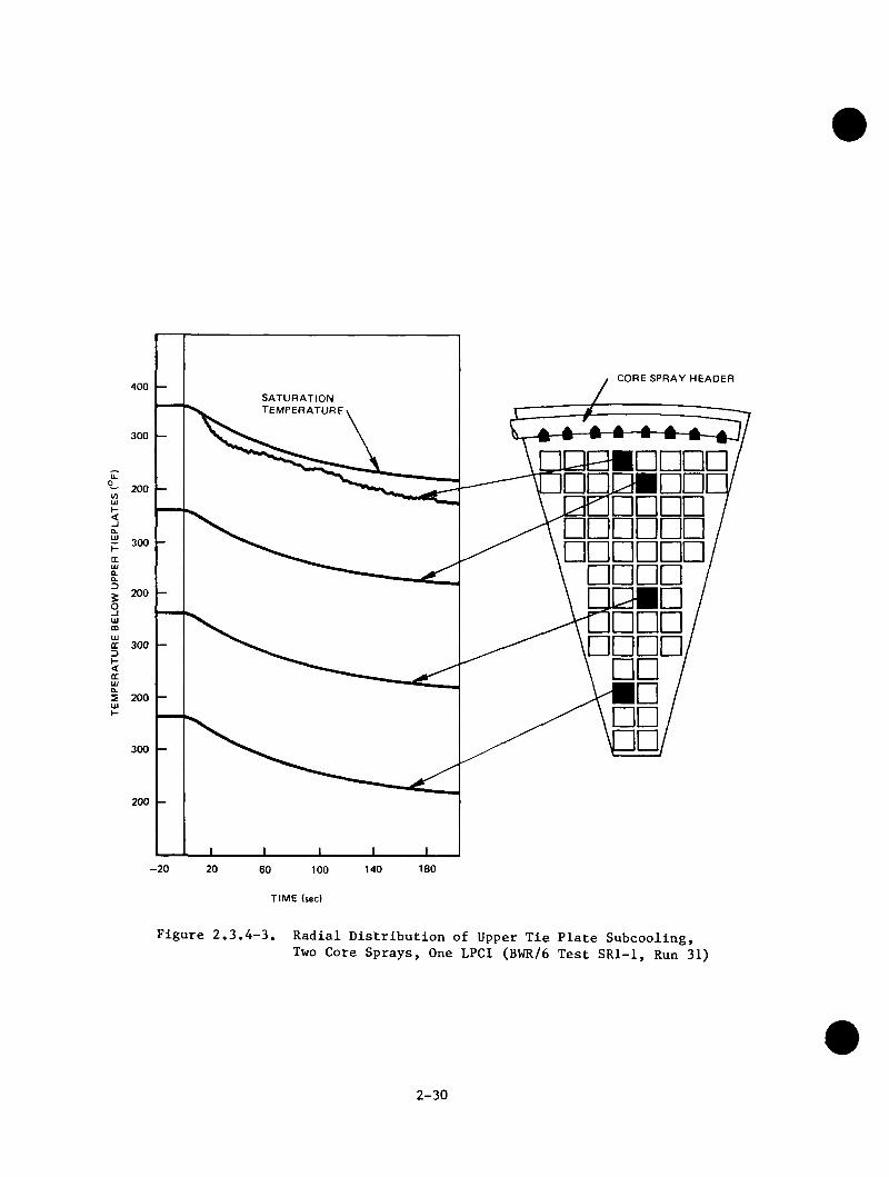
CORE SPRAY HEADER
SATURATIONt e m p e r a t u r e
□QBBDn
S 200
TIME (sec)
Figure 2.3.4-3. Radial Distribution of Upper Tie Plate Subcooling, Two Core Sprays, One LPCI (BWR/6 Test SRl-1, Run 31)
2-30
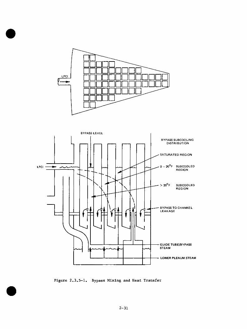
LPCI
□[□ □ □ □ □ □□□□□□□□□ □□□□□□□□□□□□a□ □ □ □ □Q
BYPASS LEVEL
BYPASS SUBCOOLING DISTRIBUTION
SATURATED REGION
0 - 20 F SUBCOOLED REGION
LPCI
SUBCOOLEDREGION
> 20 F
BYPASS TO CHANNEL LEAKAGE
GUIDE TUBE/BYPASS STEAM
LOWER PLENUM STEAM
Figure 2.3.5-1. Bypass Mixing and Heat Transfer
2-31
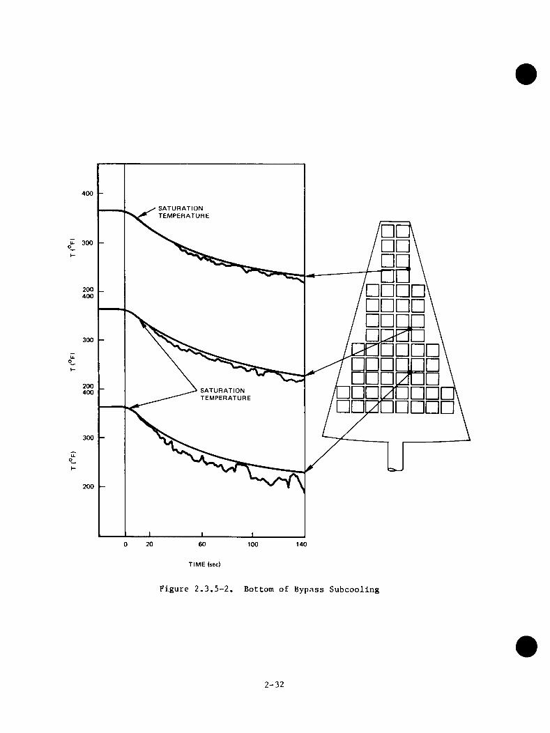
400
SATURATIONTEMPERATURE
200400
□ □300
□ □on□□200400 □ □ □ □
□ □ □ □
SATURATIONTEMPERATURE
□ □
300
200
20 600 100 140
TIME (sec)
Figure 2.3.5-2. Bottom of Bypass Subcooling
2-32
2.3.6 Lower Plenum Mixing and Jet Pump Fraction
The mixing of subcooled water with the contents of the lower plenum was evaluated from the results of both separate effects tests and system response tests. These Investigations were of Interest to determine the degree to which the temperatures In the lower plenum stratify as well as to compare the refilling characteristics of both the BWR/A and BWR/6 designs which differ In the location of LPCI Injection.
Separate effects tests were run with subcooled LPCI water Injected Into thelower plenum through the jet pumps. This configuration Is representative of theBWR/4 ECCS. The objective of these tests was to Identify the controlling phenomena associated with the condensation of steam In the lower plenum by the LPCI water. As the lower plenum fills, the phenomena controlling the steam condensation and lower plenum subcooling passes through four phases, as shown In Figure 2.3.6-1. These four phases are: (1) steam condensation In jet pumps; (2)jet pumps filling, reduced condensation In jet pumps; (3) jet pump spill over, condensation In the annulus; and (4) annulus full, condensation In lower plenum only. Variations In system parameters do not change these basic phases, though the times at which various phases begin and end, and the amount of condensation that occurs within each phase, are affected. Variations In system parameters do affect the time required to fill the lower plenum, which In turn affects the timerequired to condense the steam Injected Into this region.
System response tests were run with both the BWR/4 and the BWR/6 configurations of LPCI location. For the BWR/4 case, condensation In the lower plenum by LPCI Injected through the jet pump Is shielded from the vapor continuous region by the two-phase mixture in the jet pump; therefore, the LPCI fluid enters directly Into the two-phase pool region In the lower plenum which makes a greater condensing capacity available In the lower plenum region. As shown by a string of temperature measurements made In the lower plenum near the jet pump exit in Figure2.3.6-2, there is an early and large stratified subcooled region accumulating below the two-phase Interface. For the BWR/6 case, where LPCI is injected into the bypass region, subcooled water flows from the bypass to the inlet region of each bundle. The distribution of side entry orifice (SEO) subcooling is shown in Figure 2.3.6-3.
The BWR/4 LPCI Injection into the jet pumps quickly fills and subcools the lower plenum and speeds bottom reflooding of the core. The BWR/6 LPCI injection
2-33
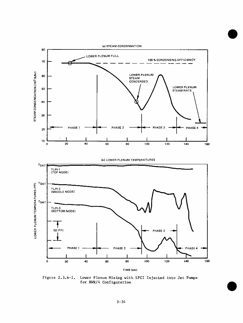
la) STEAM CONDENSATION
LOWER PLENUM FULL100 % CONDENSING EFFICIENCY
LOWER PLENUMSTEAMCONDENSED
60
LOWER PLENUM STEAM RATE
40
30
PHASE 3PHASE 2PHASE 1 PHASE 4
20 40 60 80 100 1200 140 160
n
ZgI-<zUJOzoos<
(b) LOWER PLENUM TEMPERATURES
TsatTLPI-1 (TOP NODE)
e ■’’satCOUJXHC T s a tUI0.SUJI-SDZUJ_lQ.OC
TLPI-2(MIDDLE NODE)
TLPI-3(BOTTOM NODE)
PHASE 3UJsO_j
PHASE PHASE 2 PHASE 4
1601400 100 1208040 6020
TIME (tec)
Figure 2.3.6-1. Lower Plenum Mixing with LPCI Injected into Jet Pumps for EWR/4 Configuration
2-34
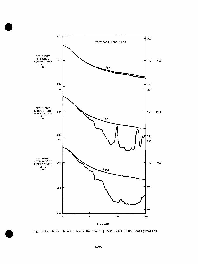
PERIPHERY TOP NODE
TEMPERATURE LP 1-1 (OF)
PERIPHERY MIDDLE NODE
TEMPERATURE LP 1-2 (OF)
PERIPHERY BOTTOM NODE TEMPERATURE
LP 1-3 (OF)
400 200TEST EA3.1 (LPCS, 2LPCI)
300 150
Tsat
200 100
400 200
150300
TSAT
200 100400 200
300 150
Tsat
100200
50
1000 50 100 150
(°C)
(OC)
(OQ)
TIME (sec)
Figure 2.3.6-2. Lower Plenum Subcooling for BWR/4 ECCS Configuration
2-35
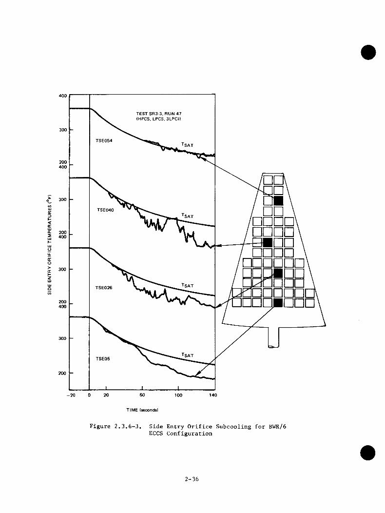
400
TEST SR3-3, RUN 47 (HPCS, LPCS, 3LPCI)
300
TSE054 Tsat
200400
300CO
I □ □ \ □ □ □ □ □□□□ a in n □ □ □ □
LUcDTSE040
SAT<GCUJ^ 200 5 400HUJUu.OCo^ 300KZUJUJOV) □ □ □ □
TSE026
□ □200400
300
TSE05
200
600 20-20 140100
TIME Isecondil
Figure 2.3.6-3. Side Entry Orifice Subcooling for BWR/6 ECCS Configuration
2-36

into the bypass also supplies subcooled liquid to the lower plenum but not as rapidly or as subcooled as the BWR/4 jet pump injection of the LPCI. For the BWR/6, two and three LPCI's are more effective than one LPCI. The increased LPCI injection produces increased subcooling in the lower plenum and reduces the void fraction in the jet pump. This latter effect results in a larger mass being supported within the core shroud due to a manometer effect as indicated in Figure 2.3.6-4. All of the BWR/4 tests were performed with two LPCI's, so similar direct sensitivity comparisons are not available. The refilling characteristics of the two design are compared in Figures 2.3.6-5 and 2.3.6-6.
2.3.7 Parallel Channel Effects
Multichannel behavior was observed during both the separate effects tests and the system transients. This behavior is illustrated schematically in Figure2.3.7-1. At the initiation of the transients, the entire core was operating in a CCFL mode similar to the "average" bundle in the figure. Steam flowing up from the lower plenum caused CCFL at the inlet orifice located at the bottom of the bundles and limited the drainage of the two-phase mixture in the bundles. The bundles filled by leakage from the bypass and liquid draining from the upper plenum (drainage limited by CCFL at the upper tieplate). This uniform mode of operation is similar to that observed in single channel tests. As time progressed, however, multichannel behavior was established. The peripheral bundles started to fill with liquid due to a smaller inlet orifice limiting the drainage rate. Subcooled CCFL breakdown from above increased the filling rate. The mass accumulating in the average bundles controlled the differential pressure across the core. The other bundles filled at a rate to match the differential pressure across the average bundles. The central bundles, with their higher void fraction, soon filled to the top of the bundle with a two-phase mixture and could not accumulate additional mass to match the increasing elevation head of the average bundles. In order to maintain the equal differential pressure required across parallel channels, some central bundles had to switch to a high upflow mode to provide a flow friction pressure drop to match the elevation head of the average bundles. This upflow mode consisted of a two-phase mixture of steam from the lower plenum and liquid entering the bundle at the bottom from the bypass leakage paths. Thus the core entered a mode as shown in Figure 2.3.7-2. The bulk of the bundles operated in a CCFL mode similar to single channel tests. The peripheral bundles operated in a downflow mode, draining upper plenum liquid to the lower plenum, and some central bundles operated in an upflow mode, venting lower plenum steam.
2-37
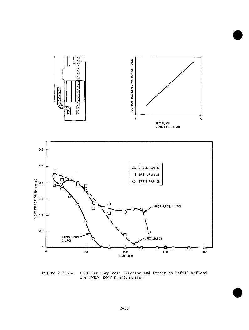
I
m
iOD0 cc1</)zII-5V)(/)<QLUJ-QCOa.0.D(/)
01JET PUMP VOID FRACTION
0.6
0.5 A S R 3-3.RUN 47
□ SRS-1,RUN36
O SR T-3 ,R U N 26
( T ^aE3aVzo 0.3h“U<(Tu.
HPCS. LPCS. 1 LPCI
9o>
N dHPCS, LPCS. 3 LPCI LPCS. 2LPCI
0 50 100 150 200TIME (sec)
Figure 2.3.6-4. SSTF Jet Pump Void Fraction and Impact on Refill-Reflood for B.WR/6 ECCS Configuration
2-38
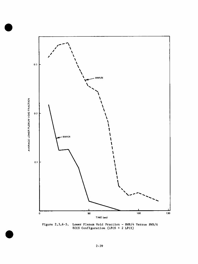
0.3
BWR/6
ZoHO<CCu.9o>sDZUJ
0.2
-I0.QCUJ§O BWR/4UJO<CCUJ><
50 100 130
TIME (sec)
Figure 2.3.6-5, Lower Plenum Void Fraction - BWR/4 Versus BWR/6 ECCS Configuration (LPCS + 2 LPCI)
2-39
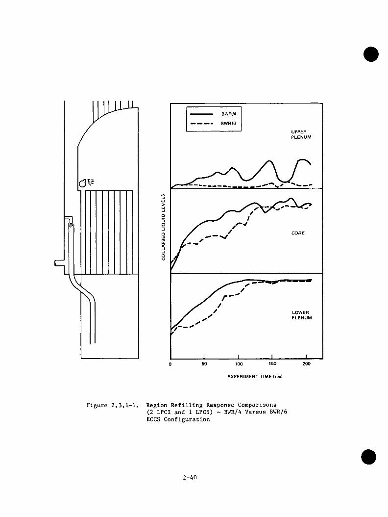
BWR/4
BWR/6
UPPERPLENUM
c/)Ui>UJ
9Da
COREOUJ</)CL<-I-JOo
LOWERPLENUM
50 100 150
EXPERIMENT TIME (sec)
200
Figure 2.3.6-6. Region Refilling Response Comparisons(2 LPCI and 1 LPCS) - BWR/4 Versus BWR/6 ECCS Configuration
2-40

N>I
i
CC —
LIQUID
CCFLLIQUID STEAM
PERIPHERAL
K<>UJUJ
AVERAGEUJ_iOzDCD
CENTRAL
ORIFICE
D IFFERENTIAL PRESSURE
Figure 2.3.7-1. Schematic of Multichannel Behavior Observed in 30-degree SSTF
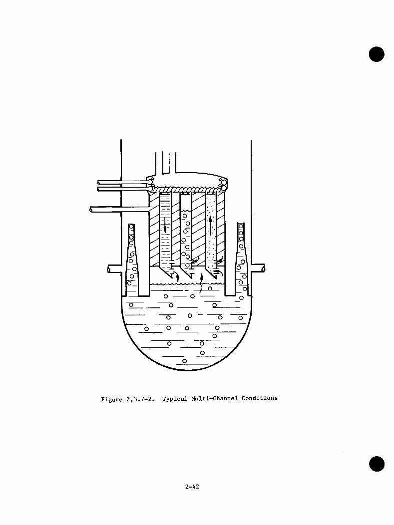
Figure 2.3.7-2. Typical Multi-Channel Conditions
2-42
In the multichannel core, subcooling at the inlet orifices does not lead to CCFL breakdown and channel draining, as it does in single channel experiments. This is due to the redistribution of lower plenum steam to the channels, and the interdependence of the channel pressure drops. SEO subcooling occurs first in the channels one row in from the periphery, and then moves radially toward the center of the core.
The above scenario resulted in global behavior slightly different from that observed in single channel tests. While the bulk of the core maintained a flow regime similar to that observed in single channel tests, the behavior of the peripheral and central bundles differed. The downflow in the peripheral bundles resulted in faster penetration of liquid to the lower plenum. The upflow mode of the central bundles allowed a vent path for lower plenum steam. This resulted in less liquid entrained out the jet pumps and allowed the level in the lower plenum to remain above the jet pump exit.
The impact of parallel channel flow is to drain mass from the upper plenumquickly and as a result keep the bottom of the jet pumps covered. With less steam escaping out the jet pumps, more water is held up in the multi-channel core and lower plenum during the pre-ECCS phase of the LOCA than in a single channel test. Every channel contains a steam-water mixture while parallel channel flow exists. Parallel channel phenomena observed in the SSTF tests indicate beneficial effects on the assessment of BWR LOCA refill-reflood performance.
2.3.8 Residual Pool in Upper Plenum
The subcooled drainage through the peripheral fuel channels, combined with saturated CCFL controlled drainage through the central fuel channels and drainage down the bypass, easily drained the ECC liquid pumped into the upper plenum. However, an effect was observed in the upper plenum that retained a residual pool at the elevation of the spray injection header, as illustrated in Figure 2.3.4-1. This pool results from cyclic interaction between subcooled CCFL breakdown and condensation changes as the upper plenum pool level moves past the ECC spray sparger elevation. When the upper plenum pool level is below the ECC injection elevation very high condensation rates occur and insufficient subcooling remains to maintain CCFL breakdown. Without CCFL breakdown the pool level increases andshields the subcooled liquid from the condensing vapor. With that, subcooled CCFLbreakdown is again established and the pool level drains down below the ECC inlet to repeat the cycle.
2-43
Figure 2.3.8-1 illustrates the direct correspondence between mass of residual liquid and spray sparger elevation for three different configurations. The data indicate that residual pools are established at the spray header elevation (with void fractions of approximately 50%) independent of whether the tests started withpool levels above or below that elevation.
The residual upper plenum pool effectively accomplishes the distribution ofECC liquid to the top of all channels. Hence, the previously assumed requirementfor appropriate ECC nozzle design to distribute liquid in a dry steam environment is not necessary. The uniformity of the pool across the top of the core is indicated by Figure 2.3.8-2.
Although the referenced figures are from separate effect upper plenum mixing tests in which the bypass was initially full and was held full throughout the test, all of the system response tests also showed immediate formation of a residual pool before the bypass was full.
2.3.9 ECCS Effectiveness During System Transients
The system transients tests were designed to combine all the phenomena in a test simulating part of the blowdown and the refill period. These tests were conducted by initializing the mass distribution to that expected in the transient when the pressure reaches 150 psia (approximately 50 seconds) and then blowing the system down through a break.
The results of a BWR/4 simulated large-break LOCA are shown in Figure 2.3.9-1. The system was completely filled within 100 seconds ot the start of the test (approximately 150 seconds into a LOCA). Figure 2.3.9-2 shows, however, that the bundles were completely filled with a two-phase mixture within 50 seconds (approximately 100 seconds into the LOCA). This test also illustrated the effectiveness of the BWR/4 low pressure injection into the jet pump. The lower plenum was rapidly filled and very little liquid was lost out the break.
The system response tests simulating BWR/6 demonstrate rapid reflooding of the fuel channels by the ECC Systems during blowdown transients over the range of interest (e.g., different break sizes, ECC temperatures, etc.). As shown in Figure 2.3.9-3, all channels start reflooding upon initiation of ECCS injection, due to CCFL at the inlet orifices that holds up water entering the channels from the bypass, even before the lower plenum is refilled. The subcooled
2-44
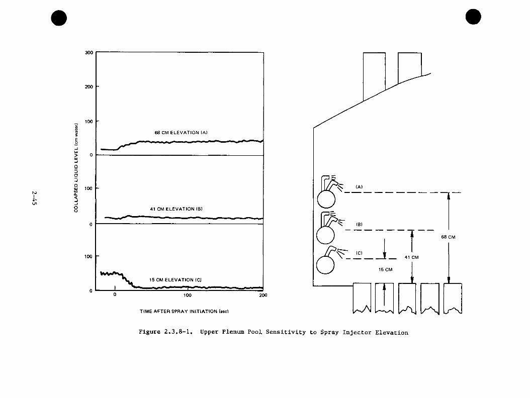
NJI
300
200
1000>(9iEu
68 CM ELEVATION (A)
-jUJ>UJ
95oo
100UIV)Q.<oo 41 CM ELEVATION (B)
100
15 CM ELEVATION <C)
200100
TIME AFTER SPRAY IN IT IATIO N iseci
(A)
(B)
68 CM
(Cl
15 CM
Figure 2.3.8-1. Upper Plenum Pool Sensitivity to Spray Injector Elevation
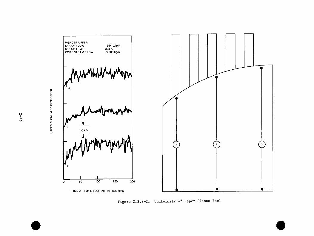
N3Io
zo0.w
<SDZ
HEADER UPPER SPRAY FLOW SPRAY TEMP.CORE STEAM FLOW
1654 L/min 308 K 27300 kg/h
1.0 kPa
±0 50 100 150 200
TIME AFTER SPRAY IN IT IATIO N (sec)
Figure 2.3.8-2. Unifomiity of Upper Plenum Pool
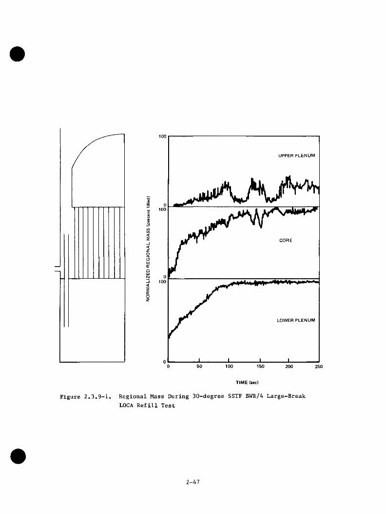
100
<<zoGCOLUN
GCOz
UPPER PLENUM
III
LOWER PLENUM
150 200 250
TIM E (sec)
Figure 2.3.9-1. Regional Mass During 30-degree SSTF BWR/4 Large-Break LOCA Refill Test
2-47
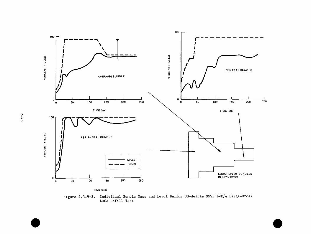
hoI00
100
OUJ
u.KZUJoGCUJCL
AVERAGE BUNDLE
250200100 150500TIME (sec)
100
QUJ
PERIPHERAL BUNDLE
u.I-ztuoocUJa.
MASS
LEVEL
200100 150 250500
100
CENTRAL BUNDLE
25050 150100 200
TIME (sec)
LOCATION OF BUNDLES IN 30°SECTOR
TIME (sec)
Figure 2.3.9-2. Individual Bundle Mass and Level During 30-degree SSTF BWR/4 Large-Break LOCA Refill Test
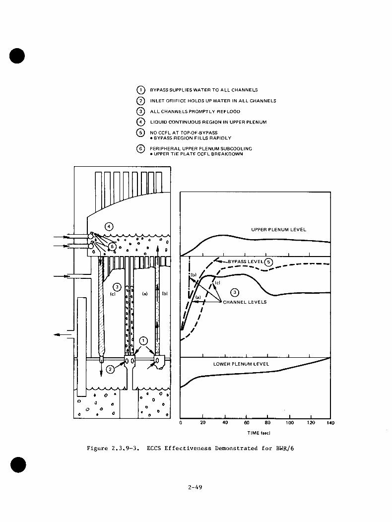
o©©©©©
BYPASS SUPPLIES WATER TO ALL CHANNELS
INLET ORIFICE HOLDS UP WATER IN ALL CHANNELS
ALL CHANNELS PROMPTLY REFLOOD
LIQUID CONTINUOUS REGION IN UPPER PLENUM
NO CCFL AT TOP-OF-BYPASS• BYPASS REGION FILLS RAPIDLY
PERIPHERAL UPPER PLENUM SUBCOOLING• UPPER TIE PLATE CCFL BREAKDOWN
UPPER PLENUM LEVEL
BYPASS LEVELi
CHANNEL LEVELS
LOWER PLENUM LEVEL
20 40 80 1200 60 100 140
TIME (sec)
Figure 2.3.9-3. ECCS Effectiveness Demonstrated for BWR/6
2-A9
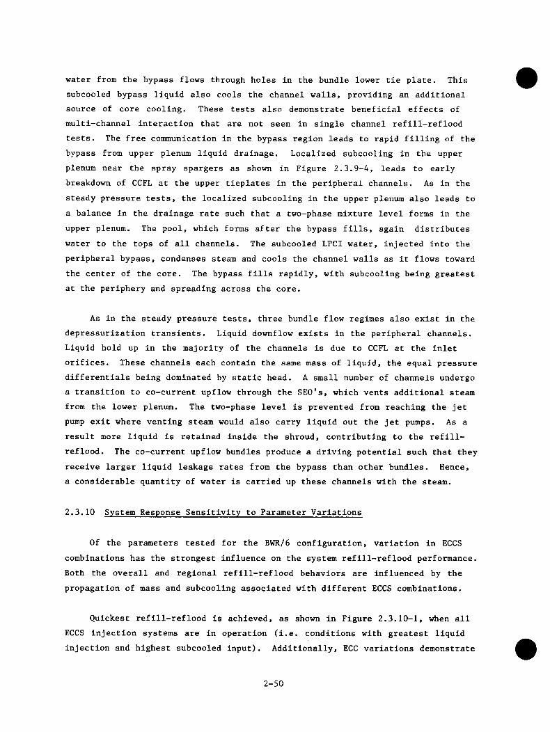
water from the bypass flows through holes in the bundle lower tie plate. This subcooled bypass liquid also cools the channel walls, providing an additional source of core cooling. These tests also demonstrate beneficial effects of multi-channel interaction that are not seen in single channel refill-reflood tests. The free communication in the bypass region leads to rapid filling of the bypass from upper plenum liquid drainage. Localized subcooling in the upper plenum near the spray spargers as shown in Figure 2.3.9-4, leads to early breakdown of CCFL at the upper tieplates in the peripheral channels. As in the steady pressure tests, the localized subcooling in the upper plenum also leads to a balance in the drainage rate such that a two-phase mixture level forms in theupper plenum. The pool, which forms after the bypass fills, again distributeswater to the tops of all channels. The subcooled LPCI water, injected into the peripheral bypass, condenses steam and cools the channel walls as it flows toward the center of the core. The bypass fills rapidly, with subcooling being greatest at the periphery and spreading across the core.
As in the steady pressure tests, three bundle flow regimes also exist in the depressurization transients. Liquid downflow exists in the peripheral channels. Liquid hold up in the majority of the channels is due to CCFL at the inlet orifices. These channels each contain the same mass of liquid, the equal pressure differentials being dominated by static head. A small number of channels undergo a transition to co-current upflow through the SEO's, which vents additional steam from the lower plenum. The two-phase level is prevented from reaching the jet pump exit where venting steam would also carry liquid out the jet pumps. As a result more liquid is retained inside the shroud, contributing to the refill- reflood. The co-current upflow bundles produce a driving potential such that they receive larger liquid leakage rates from the bypass than other bundles. Hence, a considerable quantity of water is carried up these channels with the steam.
2.3.10 System Response Sensitivity to Parameter Variations
Of the parameters tested for the BWR/6 configuration, variation in ECCS combinations has the strongest influence on the system refill-reflood performance. Both the overall and regional refill-reflood behaviors are influenced by the propagation of mass and subcooling associated with different ECCS combinations.
Quickest refill-reflood is achieved, as shown in Figure 2.3.10-1, when all ECCS injection systems are in operation (i.e. conditions with greatest liquid injection and highest subcooled input). Additionally, ECC variations demonstrate
2-50

92 =>oZ J IUJ . -I Q c0. UJft ^UJ 5 m Q- J >u
5 2,i >- UJm OC
2£| £ Q- t
UJ U.H °.< >■ UJsi IE DC“• UJ 3 ^ I p!I- i <IT oc tcS UJ mS O- % 0. 23 UJ
30
20
350 450
SATURATIONTEMPERATURE
425300
400250
350 450
SATURATIONTEMPERATURE300 425
400250
14060 1000
IE
o
TIME (sec)
Figure 2.3.9-4. Upper Plenum Liquid Continuous Region Demonstrated
2-51
(3
V)<5_i<zooUIGCQUJN_l<sccoz
LEGEND
SR3-3(HPCS, LPCS, 3 LPCI)
SR3-1(LPCS, 2 LPCI)
100SRT-3(HPCS, LPCS, 1 LPCI REFERENCE CASE)
UPPER PLENUM
0100
CORE
0100
LOWER PLENUM
0 2001000
TIME (sec)
Figure 2.3.10-1. Effect of ECCS Combinations
2-52
that low pressure coolant injection (LPCI) systems provide very effective refill-reflood performance. This is due to quicker delivery of ECC subcooling to the lower plenum, which condenses the steam generated in that region and reduces liquid loss through the jet pump for quicker lower plenum refill.
Single ECCS (HPCS) operation demonstrates efficient distribution of injected ECC liquid as shown in Figure 2.3.10-2. Liquid accumulation in the annulus and liquid loss out of the break are both minimal with single ECCS operation. As a result, the injection liquid from the single ECCS is concentrated in the core internals.
Figure 2.3.10-3 demonstrates the trend of increased system depressurization with increased ECCS injection for cases with 0, 1, 3, and 5 ECCS in operation. For these tests increased ECCS injection, and corresponding increased subcooled input, condensed additional steam and depressurized the system more quickly. Core spray ECC injection, by virtue of its' dispersed liquid distribution characteristics, provides more effective steam condensation and system depressurization than does the LPCI system. Much of the LPCI subcooling accumulates in the bypass where direct contact with, and condensation of, vapor is limited. The decreased subcooling in the upper plenum region, relative to the bypass region, results from the higher steam condensation associated with subcooled core spray.
Variation in initial system mass and break area influence vessel depressurization consistent with expected performance as shown in Figures 2.3.10-A and 2.3.10-5. The system refill-reflood characteristics however, are not changed significantly by these parameter variations. The system refill-reflood characteristics are also relatively unaffected by variation in ECCS temperature.
The BWR/4 ECCS configuration test responses are relatively insensitive to parameter variations. Similar rapid core reflooding occurred for all variations in ECCS temperature and break area. The only new phenomena observed in these tests is condensation of annulus steam by subcooled LPCI water spilling out of the jet pumps. This condensation causes small periodic pressure perturbations. This phenomena, which is most pronounced in the small break test, has little impact on the core reflooding response.
2-53
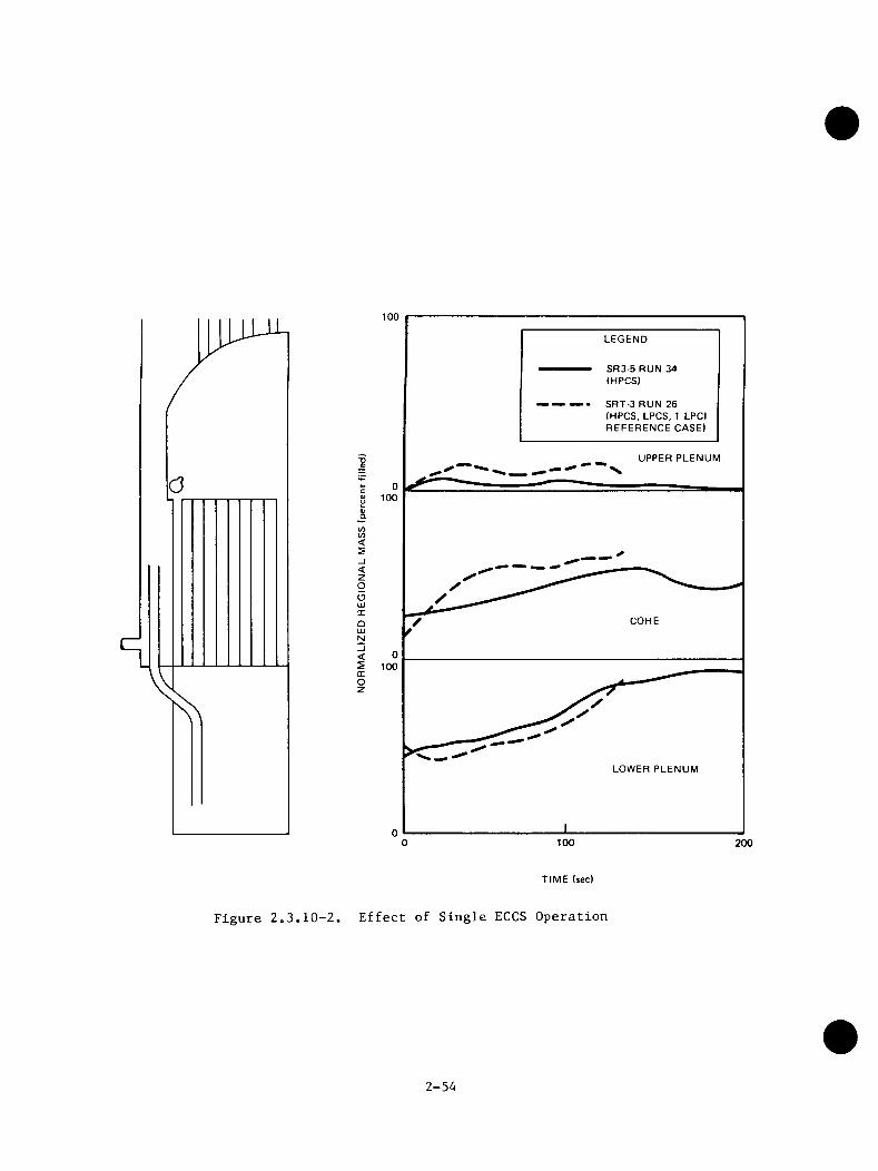
100LEGEND
SR3-5 RUN 34 (HPCS)
SRT-3 RUN 26 (HPCS, LPCS, 1 LPCI REFERENCE CASE)
UPPER PLENUM
c0)uQ}a100
COCO<5_I<zgoUJOCQUi
COREN
< 05 100cc o z
LOWER PLENUM
1000 200
TIME (sec)
Figure 2o3.10-2. Effect of Single ECCS Operation
2-54
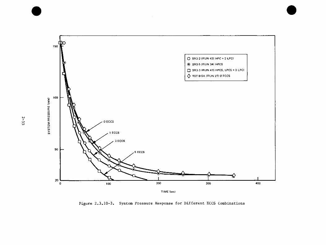
N)ILnOi
150
O SR3-2 (RUN 43) HPC + 2 LPCI
(S) SR3-5 (RUN 34) HPCS
□ SR3-3 (RUN 47) HPCS, LPCS + 3 LPCI
^ TST-9-5A (RUN 27) 0 ECCS
100.2Q.UJGCD</>U)UJcc012UJHU)>C/J
0 ECCS
1 ECCS
3 ECCS
505 ECCS
20 200 4003000 100TIME (sec)
Figure 2o3,10-3, System Pressure Response for Different ECCS Combinations
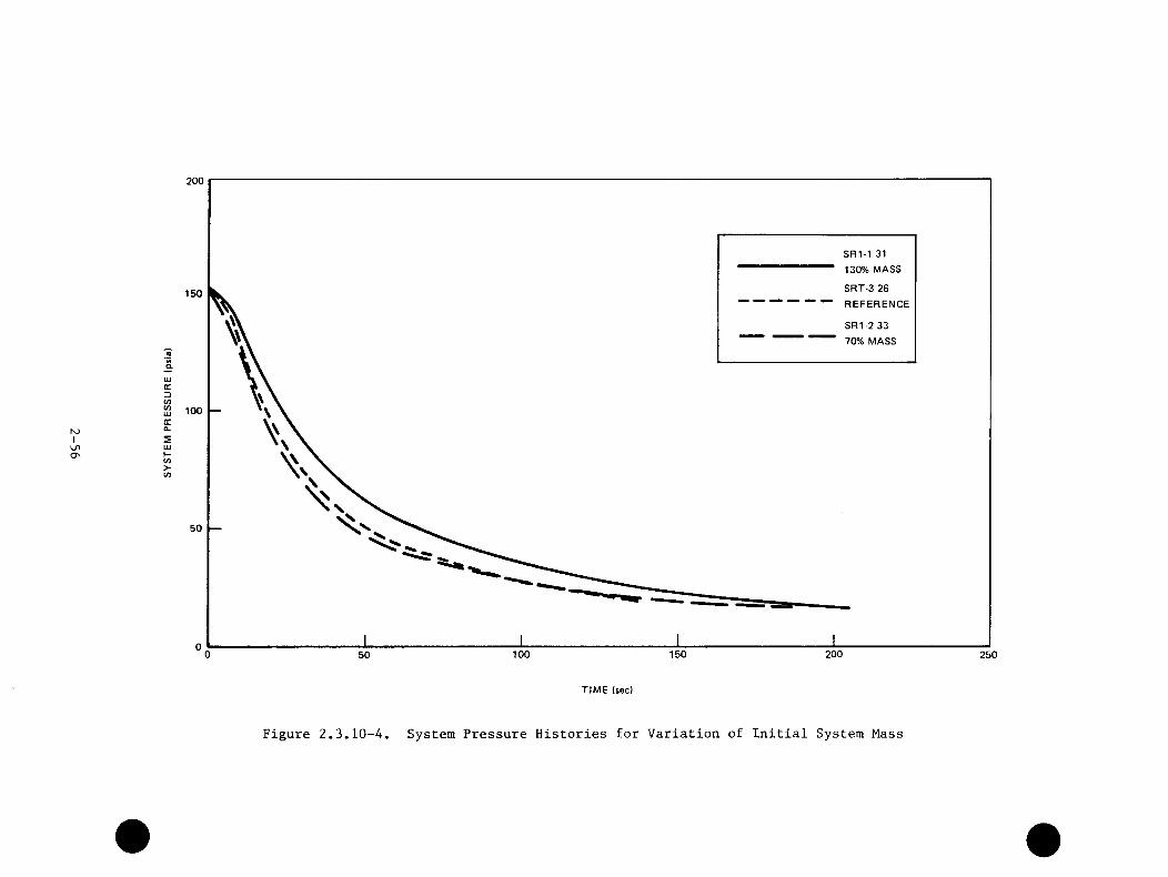
K3ILno
200
SRI-1 31 130% MASS
SRT-3 26 REFERENCE
150
SRI-2 33 70% MASS
(0Q.UJtrDw 100ocQ.2UJCO>CO
50
150 200100 25050
TIME (sec)
Figure 2,3.10-4. System Pressure Histories for Variation of Initial System Mass

200
150TEST S R M RUN 311.0 DBATEST SR2-2 RUN 48 0.45 DBA(0
aUJo;DViUJ 100
UJVi>Ui
150 200 250100500TIME (sec)
Figure 2«3.10-5. System Pressure Response for 1,0 DBA and 0.45 DBA Break Areas
2.A TASK A.7 - MODEL DEVELOPMENT
The overall BWR Refill-Reflood Program was designed to develop a better understanding of phenomena controlling the refill and reflood phases of BWR LOCAs and to provide a basis for assessing assumptions used in establishing BWR LOCA safety margins. A key objective was to provide a basis for, and support to, the development of best-estimate BWR system thermal-hydraulic codes for LOCA's. This task was especially important because full scale experiments are impractical and an accurate system code is necessary to synthesize the information from various smaller scale tests.
It was decided to base the BWR best estimate model development on the TRAC code. TRAC (Transient Reactor Analysis Code) is a computer code for best-estimate (BE) analysis of the thermal hydraulic conditions in a reactor system. TRAC was originally developed by Los Alamos National Laboratory for the analysis of
(9)pressurized water reactors . The development of a boiling water reactor version was initiated in 1979 as a cooperative technical effect between General Electric Company and Idaho National Engineering Laboratory.
A key feature of TRAC is a high degree of modularity and a stable numerical method. TRAC thus provides a framework where models for individual reactor components and physical phenomena can easily be interchanged. Furthermore, the free specification of the geometry allows the simulation of almost any geometry ranging from simple basic phenomena tests through system performance tests to complicated reactor systems. Consequently, the TRAC framework is a good base around which a best estimate BWR code can be developed. Thus, the primary effort focused on identifying model changes and additions necessary to accurately predict the full range of BWR thermal hydraulics. Structurally the major code change necessary was to simulate the fuel channels. It was also necessary to develop models for components unique to the BWR. Specific component model requirements included jet pumps, steam separators, steam dryers, and the BWR upper plenum with peripheral ECC spray spargers. A number of additional physical modeling features were necessary to achieve accurate predictions of physical phenomena particularly important for the BWR. These include subcooled boiling models, improved critical heat flux models, radiation heat transfer models, and accurate interphase shear modeling. An important subset of the interphase shear package was to assure accurate characterization of counter current flow phenomena at local restrictions.
2-58

The system transient tests have shovm that multidimensional and multichannel effects have the potential to significantly improve the system response over that observed in single channel tests. These results cannot be applied directly to a BWR, however, since these are not true integral tests simulating the entire transient. In addition, the SSTF did not have heated rods. Thus some mechanism is required to bridge the gap between single and multiple channel test results and provide for extrapolation to the BWR. The mechanism for this is the BWR-TRAC code. TRAC was assessed with data from these facilities to evaluate the modeling adequacy with representative full-scale BWR phenomena. TRAC is the primary method to provide a best estimate evaluation of BWR response and to evaluate the 'models used in the licensing of BWRs.
A category of model development was identified to improve the general thermal hydraulic prediction capabilities of the TRAC code. These included stratified flow modeling, break flow modeling, tracking of two-phase levels, virtual mass and the general heat transfer correlation package together with a consistent flow regime map. Finally, it was identified that the high cost of TRAC code calculations dictated improvements in calculation efficiency. Candidates included improved numerical schemes and smoother correlation transitions.
In order to obtain a computer code able to capture the major phenomena in a BWR LOCA, and which could be used to analyze the test facilities, early in the program it was decided to approach the development in two parts. The first partwas planned to incorporate preliminary models that were necessary to simulate themajor characteristics of a BWR LOCA. Plans for the second part included updating the preliminary models, as necessary, and completing the model additions to achieve the best estimate prediction capability goal. The actual development of the BWR-TRAC loss of coolant model followed this plan very closely. The BWR development work was divided primarily between General Electric and the Idaho National Engineering Laboratory, with consultation by the original TRAC development team at Los Alamos National Laboratory. The initial code versions were completed in 1981 and the final loss of coolant modeling in 1982. The majorimprovements made to the code are summarized in Table 2.4-1.
The models described in this report are included in the GE working version TRACB02, and have been made available to Idaho National Engineering Laboratory (INEL) for inclusion in subsequent model releases.
2-59
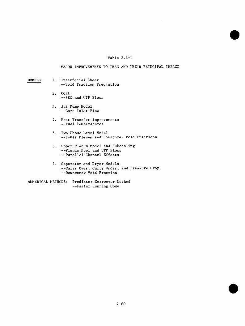
Table 2.4-1
MAJOR IMPROVEMENTS TO TRAC AND THEIR PRINCIPAL IMPACT
MODELS: 1. Interfacial Shear— Void Fraction Prediction
2. CCFL— SEO and UTP Flows
3. Jet Pump Model— Core Inlet Flow
4. Heat Transfer Improvements — Fuel Temperatures
5. Two Phase Level Model— Lower Plenum and Downcomer Void Fractions
6. Upper Plenum Model and Subcooling — Plenum Pool and UTP Flows— Parallel Channel Effects
7. Separator and Dryer Models— Carry Over, Carry Under, and Pressure Drop — Downcomer Void Fraction
NUMERICAL METHODS: Predictor Corrector Method— Faster Running Code
2-60
2.4.1 Constitutive Correlations
The basic physical phenomena in TRAC are described by the conservation equations for mass, momentum and energy together with constitutive correlations for shear, mass and heat transfer. The shear stresses include the wall friction and the interfacial shear and are the controlling mechanism for the void fraction. The heat models include the wall heat transfer and the interfacial heat transfer, which together with a jump-condition describe the evaporation and condensation. Mass transfer is included through entrainment correlations.
The constitutive correlations are dependent on the flow regime and separate correlations have been developed for each regime. The flow regimes included are: single-phase liquid flow, bubbly flow, churn flow, annular flow, inverted annular flow, droplet flow, and single phase steam flow. For the vessel, plenum andhorizontal pipes stratified flow is considered. A flow regime map providing aconsistent selection logic for the constitutive correlations has been developed.
A new model for the interfacial shear has been developed. The model accounts for the effect of phase and velocity profiles. Correlations for the interfacial shear and the distribution parameter have been developed for cocurrent flow from void fraction data. For counter-current flow the correlations are in agreementwith counter-current flow limitation (CCFL) data.
Improvements have been made to the heat transfer correlations in TRAC. A subcooled boiling model has been developed, a boiling length correlation has been introduced for critical heat flux, and a new correlation for the minimum point on the boiling curve has been included. Particular attention has been directed toward the heat transfer during emergency core coolant injection, and a model for thermal radiation heat transfer has been developed. This model accounts for both the surface-to-surface radiation and the interaction with the two-phase flow.
The numerical method controls the stability and accuracy of the integration. An improved numerical method in which timestep size can exceed the material Courant limit has been developed to increase the speed of TRAC calculations.
2.4.2 Component Models
A major task in the formulation of a BWR version of TRAC was to develop BWR models and components necessary to simulate a BWR. The BWR components developed
2-61
are jet pumps, steam separators, and steam dryers. The BWR models developed are the two-phase level tracking model and the upper plenum mixing model. Also a single channel option was developed for separate analysis of the fuel channel for a given system transient.
The jet pump component model is based on the TRAC TEE component, with the primary pipe simulating the suction, mixing region, and diffuser of the jet pump, and the secondary pipe simulating the nozzle.
Models were developed for conservation of momentum for the mixing region and for the pressure changes due to area changes, mixing and nozzle losses, and fractional losses in the jet pump. The models were developed for all flow regimes and tested for both single-phase and two-phase conditions.
The steam separator component model is based on the TRAC PIPE component, with the pipe representing both the stand pipe and the separator. A mechanistic model was developed for the separator based on a solution to the axial continuity equation and the axial and tangential momentum equations for both the liquid and the vapor phase. Radial profiles for the void fraction and the tangential velocities were introduced together with correlations for the frictional losses in the separator. The radial profiles and the correlations for the frictional losses were optimized using available data for two- and three-stage separators to give an accurate prediction of carryover and carryunder fractions, and the overall pressure drop for the separator.
A steam dryer model is incorporated as an integral part of the reactor vessel. The model simulates the dryer capacity as a function of the flow rate and predicts the correct pressure drop for the dryer.
To avoid the numerical diffusion inherent in the numerical scheme used by TRAC, a two-phase level model for the reactor vessel was developed. By calculating separate void fractions above and below the level together with the position and velocity of the level, TRAC is able to maintain a sharp void fraction discontinuity at a two-phase level. This is particularly significant for the mixing plenum, the downcomer and the lower plenum. A pool entrainment model was implemented together with the level model.
A separate model was developed to calculate the distribution of ECC injected into the upper plenum. Particular emphasis was given to an accurate prediction of
2-62

void and enthalpy distribution in the upper plenum, in order to provide the boundary conditions for the fuel channels, and to be able to predict CCFL and subcooled CCFL breakdown at the upper tie plate. The upper plenum conditions provide controlling phenomena for the parallel channel effects in the core.
The upper plenum models include sprays, submerged jets, and gross turbulence in the bulk fluid. If the two-phase level in the upper plenum is below the spray sparger, a spray distribution is calculated in the upper plenum and 100% condensation is assumed for the spray. If the spray spargers are covered by a two-phase level, the ECC injection is simulated as a submerged jet and' the penetration of the jet and residual subcooling at the upper tie plate are calculated. To give the right boundary conditions for the submerged jet model, a turbulence model based on Prandtl's mixing length theory for the bulk fluid has been implemented.
To reduce the cost of performing separate, detailed or parametric studies of the fuel channel for a given system transient, a single channel option was developed. The boundary conditions for the channel for a given system transient are stored on a separate file, and can subsequently be used to drive separate calculations of the fuel channel performance.
2.4.3 Code Development Assessment
To assure accurate code predictions and appropriate physical modeling, a systematic development assessment activity was implemented. The modular structure of the TRAC code facilitates assessment of individual phenomena and component models in addition to complete integral system assessment. The code assessment activity was therefore divided between 1) the developmental assessment of basic mechanism models and BWR component models and, 2) the preliminary assessment of the integral system model. This preliminary assessment against system data provided early feedback to the model design process and utilized a different data base than was used for the later qualification studies.
Typical developmental assessment comparison results illustrate the code accuracy. The interphase shear and level tracking capabilities are instrumental in predicting large and small breaks and degraded transient events. The capabilities of these models in TRAC are illustrated by comparisons with vessel blowdown data in Figure 2.4-1. Similarly, adequacy of the heat transfer models is demonstrated by comparisons with separate-effeet fuel channel heatup data as
2-63

0.8
zoI—o<(Tu.QO>
0.6
0.4 DATA
TRAC
0.2
2 3
A XIA L DISTANCE (m)
Figure 2.A-1. Vessel Void Fraction Distribution Comparison - PSTF
2-64
Illustrated in Figure 2.4-2. Representative BWR component modeling capabilities are demonstrated for the important performance characteristics of the steam separators and jet pumps in Figures 2.4-3 and 2.4-4, respectively.
Even with accurate phenomena and component models, realistic prediction of integral system response is still quite challenging due to coupling and interaction effects. Therefore, confirmation of the code comes from application to a diverse range of integral system experiments. Typical preliminary assessment data comparisons showing excellent comparison with system data are illustrated in Figures 2.4-5 and 2.4-6. Thorough qualification of the code was addressed in Task 4.8 and is discussed in the next section of this report.
2.5 TASK 4.8 - MODEL QUALIFICATION
The primary objective of the model qualification task was to assess the capability of the thermal hydraulic and core heat transfer methods for realistic prediction of components and system behavior under BWR LOCA conditions. Other objectives were to evaluate data for applicability to BWR simulation, to classify the data for intended utilization, and to determine the relative importance of relevant BWR LOCA-ECCS phenomena.
The BWR LOCA best-estimate model must provide a tool for calculation of the BWR response to all postulated LOCA events. This includes the entire spectrum of break sizes and locations. Therefore it was necessary to define the phenomena relevant to BWR response to a postulated LOCA from initiation through the blowdown, refill, and reflood phases of the LOCA transient.
A list of test facilities having potential applicability to the development, preliminary assessment, or independent assessment of best-estimate BWR LOCA Models was identified. The data base thus identified, was classified according to its intended use; model development support, model preliminary assessment, or independent assessment. Model development data was available to the model developers for use in developing empirically based model relations. Preliminary assessments data was used to deteirmine model and data deficiencies and needs, to develop simulation and nodalization strategies, to quantify the sensitivity of the model calculations to the governing phenomena, and to provide a basis from which to test the interaction of the various submodels and components in the code. Independent assessment data was used to assess the model range of applicability
2-65
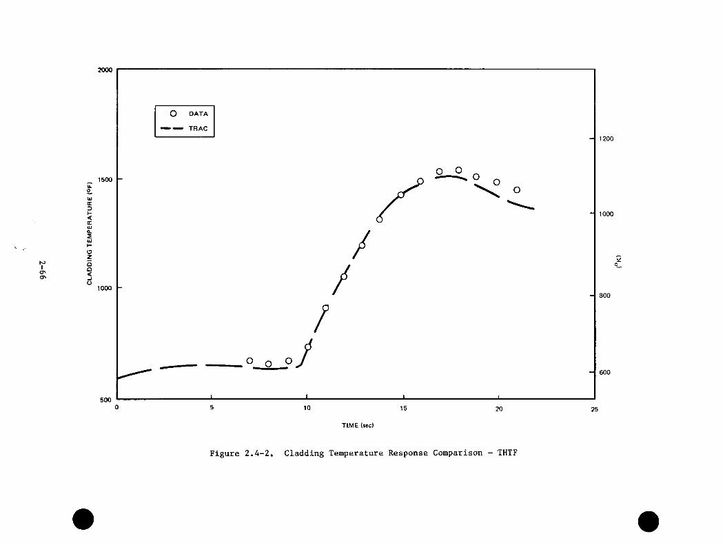
S3IoON
2000
O DATA
TRAC1200
1500u.oUJGCDI-<GCUJ
1000
a.SUJI-Ozoo<o
1000800
600
500 0 5 10 15 20 25
TIME (sec)
Figure 2*4-2, Cladding Temperature Response Comparison - THTF
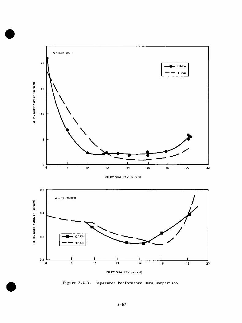
>o>(rcc<o_i<I-oI-
W = 63 KG/SEC
20DATA
TRAC
15
10
5
06 8 10 12 14 16 18 20 22
INLET QUALITY (percent)
0.5
W = 81 KG/SECc«uIms
0.4(CUJ□z3>CX<o
DATA0.3
TRAC
0.26 8 10 12 14 18 2016
INLET QUALITY (percent!
Figure 2.4-3. Separator Performance Data Comparison
2-67

N5IoOO
2.4
2.0
DATA
TRAC
0.8
Oh-<(TZ
0.4
0.2
0.4
0.6
0.8
1.00 2.0-1.0 3.0- 2.0
M RATIO
Figure 2.4-4. One-Sixth-Scale Jet Pump Performance Data Comparison
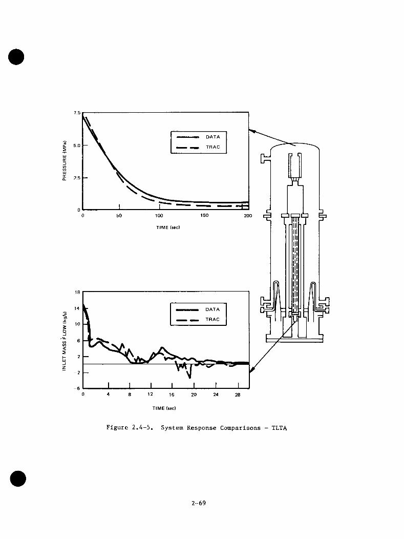
7.5
DATA
5.0 TRAC
UJirD(/)COUJQCQ. 2.5
15050 100 200TIME (sec)
DATA
TRAC
§O-I'U.COCO<SHUJ-JZ -2
-6120 4 8 2416 20 28
TIME (sec)
Figure 2.4-5. System Response Comparisons - TLTA
2-69
1
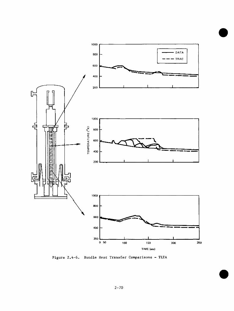
1000
DATA800
TRAC
600
400
200
1000
800oLUirD5 600trina.m 400H
200
1000
800
600
400
2000 50 250100 150 200
TIME (sec)
Figure 2.4-6. Bundle Heat Transfer Comparisons - TLTA
2-70

and to quantify modeling uncertainties. The overall development/assessment process is shown schematically in Figure 2.5-1.
Preliminary assessment of the best-estimate models was a vital element in the model development process since it provided guidance to model developers by serving as a tool to identify potential model shortcomings in time for them to be addressed prior to independent assessment and qualification. Examples of the comparisons obtained in the preliminary assessment phase were presented in the previous section.
Independent qualification of the best estimate BWR LOCA models involved comparing code predictions to the qualification data base that was not used in model development or preliminary assessment. The diverse data in the data base challenged the code to simulate parallel channel flow, EGGS mixing, GGFL, and GGFL breakdown. Table 2.5-1 summarizes the tests used for the independent qualification and indicates the conclusions drawn from the comparisons of TRAG calculated results with the test data. Typical sets of comparison plots between TRAG calculations and SSTF test data are shown in Figure 2.5-2 through 2.5-8. A detailed discussion of these comparisons is provided in the final report of the model qualification task.^^^^ A series of sensitivity studies were also performed as part of the qualification effort. The resultant recommendations for future modifications and improvements to the code are summarized in Table 2.5-2.
2-71
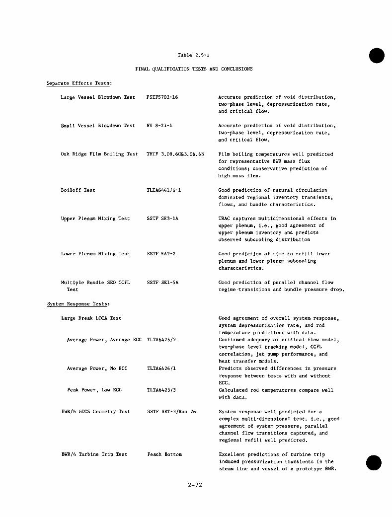
Table 2.5-1
FINAL QUALIFICATION TESTS AND CONCLUSIONS
Separate Effects Tests;
Large Vessel Blowdown Test
Small Vessel Blowdown Test
PSTF5702-16
NV 8-21-1
Oak Ridge Film Boiling Test THTF 3.08.6C&3.06.6B
Boiloff Test TLTA6441/6-1
Upper Plenum Mixing Test SSTF SE3-1A
Lower Plenum Mixing Test SSTF EA2-2
Multiple Bundle SEO CCFL SSTF SE1-5ATest
System Response Tests:
Large Break LOCA Test
Average Power, Average ECC TLTA6425/2
Average Power, No ECC
Peak Power, Low ECC
BWR/6 ECCS Geometry Test
TLTA6426/1
TLTA6423/3
SSTF SRI-3/Run 26
BWR/4 Turbine Trip Test Peach Bottom
Accurate prediction of void distribution, two-phase level, depressurization rate, and critical flow.
Accurate prediction of void distribution, two-phase level, depressurization rate, and critical flow.
Film boiling temperatures well predicted for representative BWR mass flux conditions; conservative prediction of high mass flux.
Good prediction of natural circulation dominated regional inventory transients, flows, and bundle characteristics.
TRAC captures multidimensional effects in upper plenum, i.e., good agreement of upper plenum inventory and predicts observed subcooling distribution
Good prediction of time to refill lower plenum and lower plenum subcooling characteristics.
Good prediction of parallel channel flow regime ‘transitions and bundle pressure drop.
Good agreement of overall system response, system depressurization rate, and rod temperature predictions with data. Confirmed adequacy of critical flow model, two-phase level tracking model, CCFL correlation, jet pump performance, and heat transfer models.Predicts observed differences in pressure response between tests with and without ECC.Calculated rod temperatures compare well with data.
System response well predicted for a complex multi-dimensional test, i.e., good agreement of system pressure, parallel channel flow transitions captured, and regional refill well predicted.
Excellent predictions of turbine trip induced pressurization transients in the steam line and vessel of a prototype BWR.
2-72
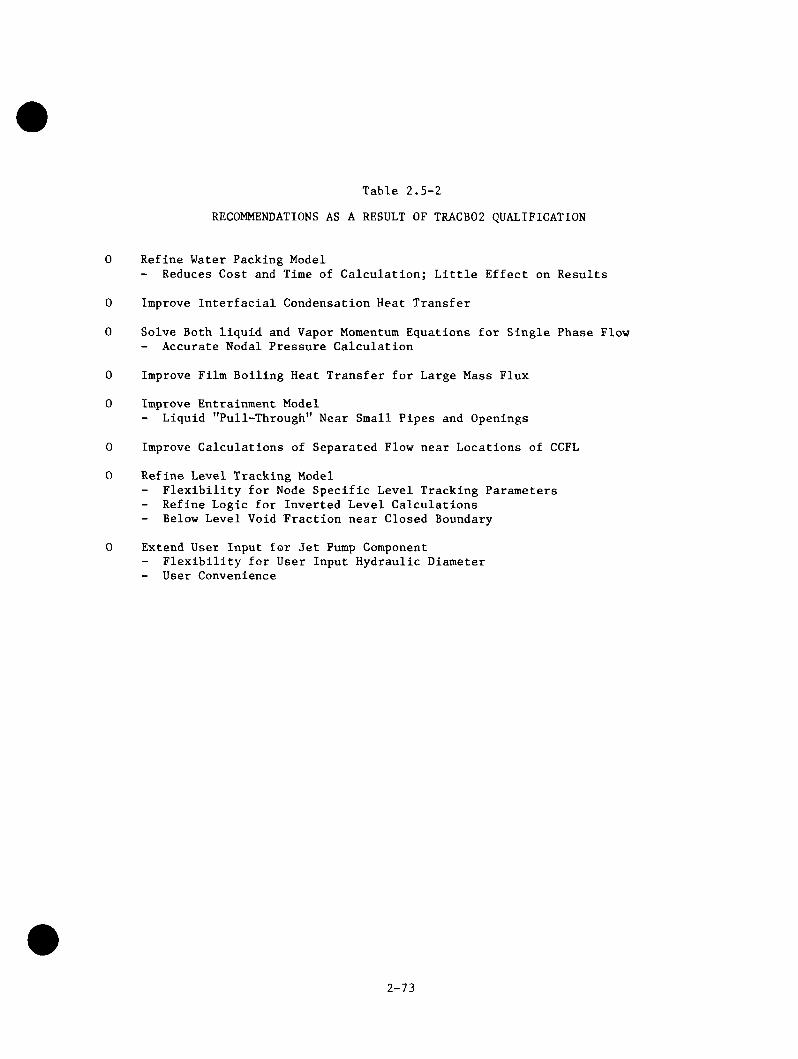
Table 2.5-2RECOMMENDATIONS AS A RESULT OF TRACB02 QUALIFICATION
0 Refine Water Packing Model- Reduces Cost and Time of Calculation; Little Effect on Results
0 Improve Interfacial Condensation Heat Transfer
0 Solve Both liquid and Vapor Momentum Equations for Single Phase Flow- Accurate Nodal Pressure Calculation
0 Improve Film Boiling Heat Transfer for Large Mass Flux
0 Improve Entrainment Model- Liquid "Pull-Through" Near Small Pipes and Openings
0 Improve Calculations of Separated Flow near Locations of CCFL
0 Refine Level Tracking ModelFlexibility for Node Specific Level Tracking Parameters Refine Logic for Inverted Level Calculations Below Level Void Fraction near Closed Boundary
0 Extend User Input for Jet Pump ComponentFlexibility for User Input Hydraulic Diameter
- User Convenience
2-73
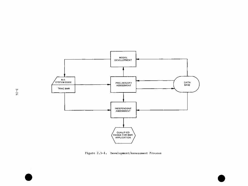
N3I
SYSTEM CODE DATABASE
TRAC BWR
’ QUALIFIED RANGE FOR BWR , APPLICATION
MODELDEVELOPMENT
PRELIMINARYASSESSMENT
INDEPENDENTASSESSMENT
Figure 2.5-1. Development/Assessment Process
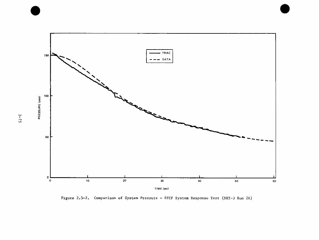
roI
TRAC150
DATA
_ 100
50
0 2010 30 40 50 60
TIME (sec)
Figure 2.5-2. Comparison of System Pressure - SSTF System Response Test (SRT-3 Run 26)
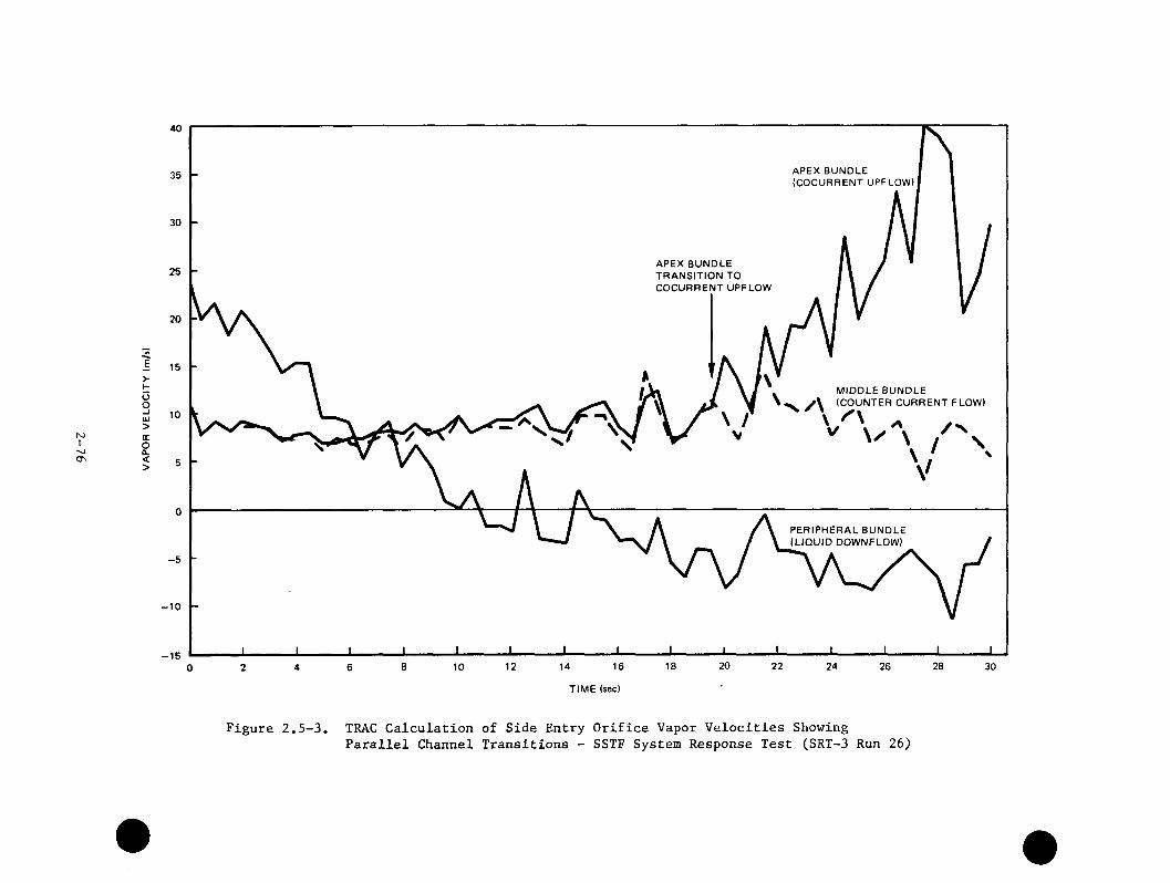
1
40
APEX BUNDLE (COCURRENT UPFLOW)
30
APEX BUNDLE TRANSITION TO COCURRENT UPFLOW
20
E>I- MIDDLE BUNDLE
^ (COUNTER CURRENT FLOW)
\ ^
oo-IUJ>GCo0.<>
PERIPHERAL BUNDLE (LIQUID DOWNFLOW)
- 5
-1 0
-1 52018 22 24 288 12 16 26 30146 1020 4
TIME (sec)
Figure 2.5-3. TRAC Calculation of Side Entry Orifice Vapor Velocities ShowingParallel Channel Transitions - SSTF System Response Test (SRT-3 Run 26)
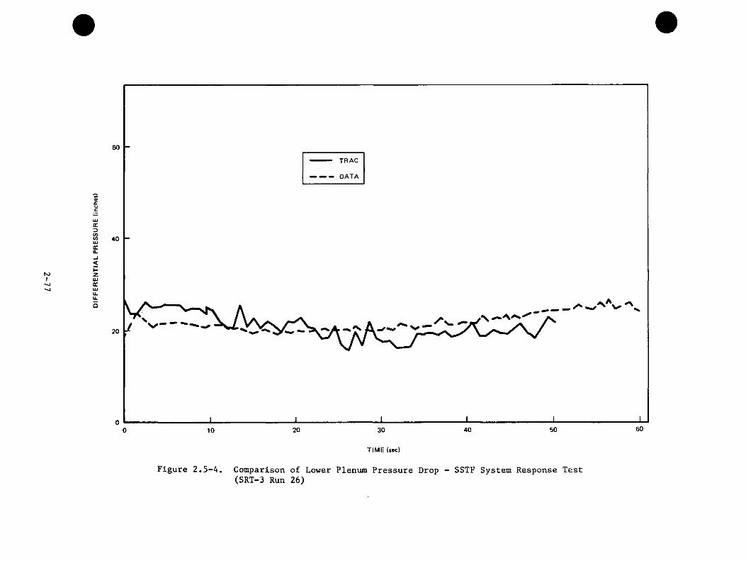
hJI
60TRAC
DATA
M9>£UcUJQCDCOCOUJXa.
40
<I-ZUJCCUJ11.u.o
60504020 300 10
TIME (sec)
Figure 2.5-4. Comparison of Lower Plenum Pressure Drop - SSTF System Response Test(SRT-3 Run 26)
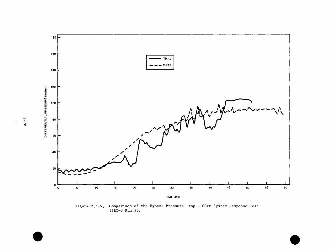
I00
180
160
TRAC
DATA
140
•5 120 a»
UJGC3 100
UJGC0. /I-J<KZUJ
80
GCUJu.u.o 60
40
35 45 5520 30 40 50 6010 250 155
TIME (sec)
Figure 2.5-5. Comparison of the Bypass Pressure Drop - SSTF System Response Test(SRT-3 Run 26)
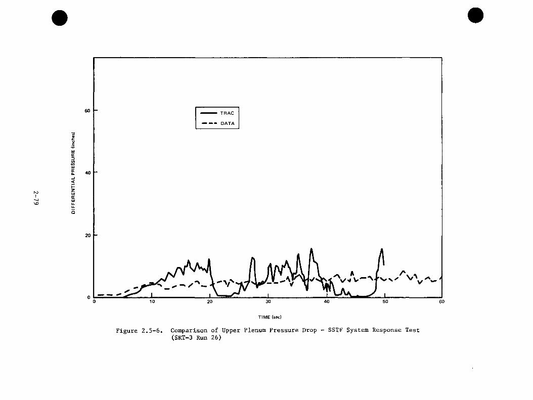
to!VO
60 TRAC
— - DATA
sc.ucUJcc3toCOUJ(ECL 40<I-ZUJCCUJu.u.O
20 -
40 50 60
TIME (sec)
Figure 2.5-6. Comparison of Upper Plenum Pressure Drop - SSTF System Response Test(SRT-3 Run 26)
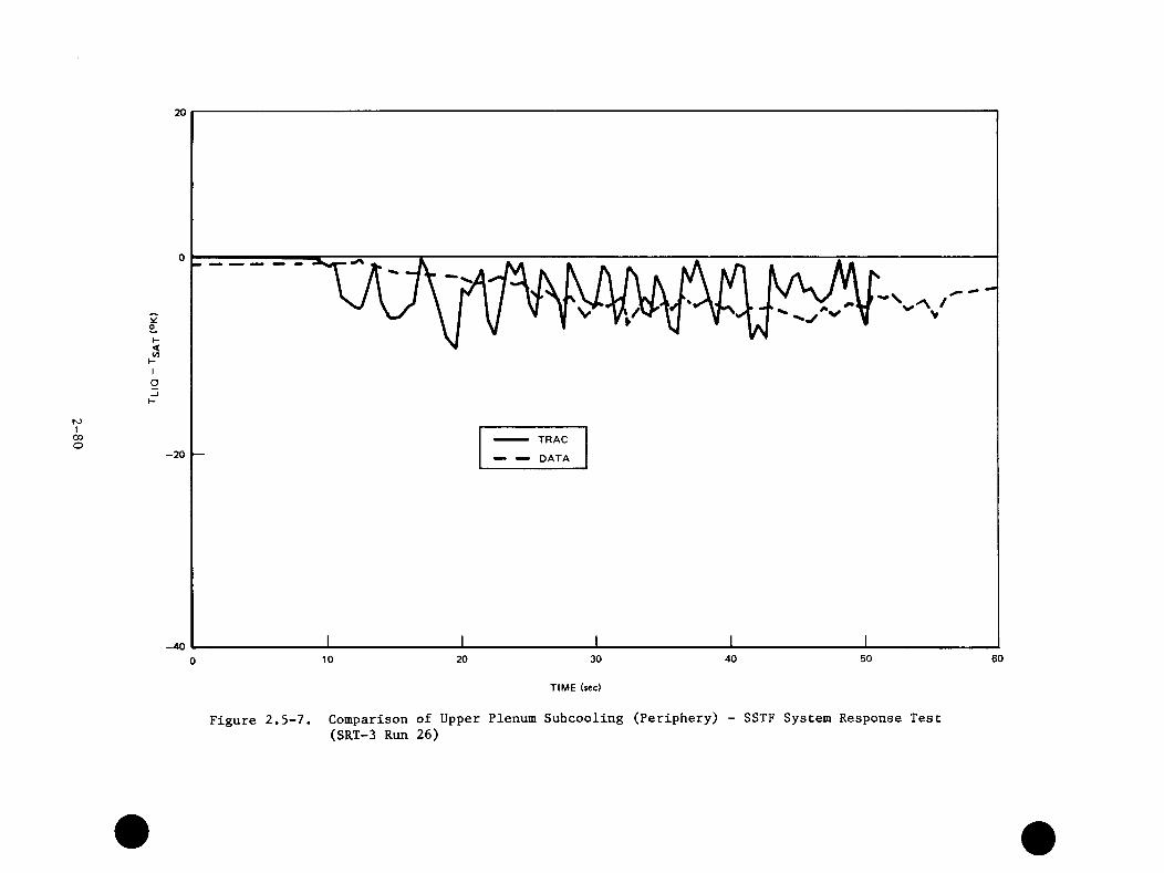
N5I
CDO
I -<WKIa
20
0
TRAC-2 0 — — DATA
-4050 6030 4020100
TIME (sec)
Figure 2.5-7. Comparison of Upper Plenum Sufacooling (Periphery) - SSTF System Response Test(SRT-3 Run 26)
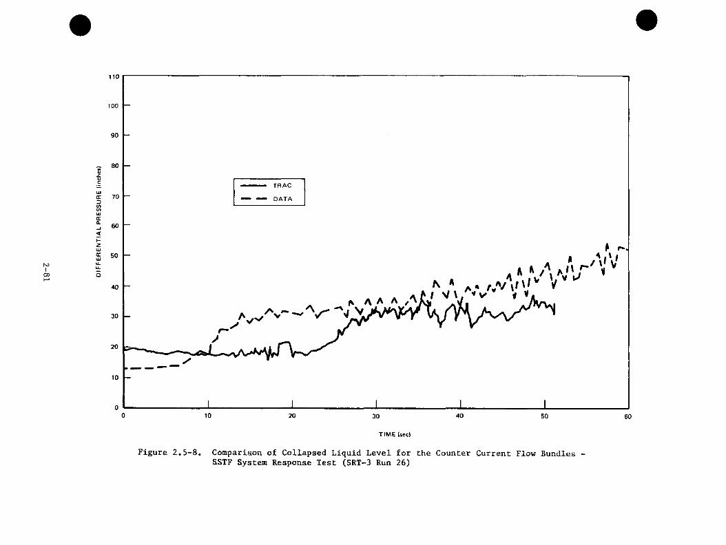
S3I
CO
110
100
90
80«•9»T R A C
UJ£C 70DwVi
— d a t a
UJQCa. 60<I -ZUJQC 5 0UJ ''''u.u. M ro .Vi/'j40
20
0 10 20 4030 50 60
T I M E (sec)
Figure 2.5-8. Comparison of Collapsed Liquid Level for the Counter Current Flow BundlesSSTF System Response Test (SRT-3 Run 26)

REFERENCES
1. G. W. Burnette and G. L. Sozzi, "Synopsis of the BWR Blowdown Heat-Transfer Program", Nucl. Safety, 20(1): 27-43 (January-February 1979).
2. W. S. Hwang and B. S. Schneidman, "BWR Blowdown/Emergency Core Cooling Program: 64-Rod Bundle Blowdown Heat Transfer ( 8 x 8 BDHT), Final Report", General Electric Co., September 1978 (GEAP-NUREG-23977, EPRl NP-1720).
3. L. S. Lee et al., "BWR Large Break Simulation Tests - BWR Blowdown/Emergency Core Cooling Program", General Electric Co., March 1981 (GEAP-24962-1 and -2, NUREG/CR-2229, EPRI NP-1783).
4. W. S. Hwang, "BWR Small Break Simulation Tests With and Without Degraded ECC Systems-BWR Blowdown/Emergency Core Cooling Program", General Electric Co., February 1981, (GEAP-24963, NUREG/CR-2230, EPRI NP-1782).
5. D. S. Seely and R. Muralidharan, "BWR Low Flow Bundle Uncovery Tests and Analysis-BWR Blowdown/Emergency Core Cooling Program", General Electric Co., February 1981 (GEAP-24964, NUREG/CR-2231, EPRI NP-1781).
6. J. E. Thompson, "BWR Full Integral Simulation Test (FIST) Program Test Plan," General Electric Co., April 1982 (GEAP-22053, NUREG/CR-2575, EPRI NP-2313).
7. J. W. Spore et all, "TRAC-BDl: An Advanced Best Estimate Computer Program for Boiling Water Reactor Loss-of-Coolant Accidient Analysis", Nuclear Regulatory Commission, October 1981 (NUREG/CR-2178).
8. J. G. M. Andersen and B. S. Shiralkar, "BWR Refill-Reflood Program Task 4.7- Model Development Task Plan," General Electric Co., March 1981 (GEAP-24932, NUREG/CR-2057, EPRI NP-1526).
9. R. J. Pryor, et al., "TRAC-PIA, An Advanced Best Estimate Computer Program for PWR LOCA Analysis", Los Alamos Scientific Laboratory, May 1979, (NUREG/ CRA-0665, LA-777-75).
10. Md. Alamgir, "BWR Ref ill-Ref lood Program Task 4.8 - TRAC-BWR ModelQualification Final Report", General Electric Co., July 1983, (GEAP-22049, NUREG/CR-2571, EPRI NP-2377).
3-1

APPENDIX A
Listing and Abstracts of Program Reports
This appendix contains a complete listing of all reports issued under the BW.'* Ref ill-Ref lood Program along with an abstract of each report. Also shown for each report are the report number and issue date for the version of the report issued by each of the sponsoring organizations, i.e., GEAP- for General Electric, NUREG/CR- for the U. S. Nuclear Regulatory Gommission, and EPRI NP- for the Electric Power Research Institute.
IssueDate
1/818/8110/81
Report Number
GEAP-24924 NUREG/CR-1972 EPRI NP-1522
_____ Report Title, Author(s), and Abstract____
BWR Refill-Reflood Program Task 4.1 - Program Plan, G. W. Burnette, General Electric Company.
1/8011/802/81
GEAP-25272 NUREG/CR-1558 EPRI NP-1523
The BWR Refill-Reflood Program is described. This program will develop more detailed experimental information, particularly in large scale facilities, and realistic modelling capability for the refill and reflood phases of hypothetical loss-of-coolant accidents in BWRs. Included in this document are a general strategy discussion, brief descriptions of the experimental facilities to be used including capabilities and limitations, descriptions of the various experimental tasks, descriptions of the model development and model qualification tasks, the planned documentation and schedule information.
BWR Refill-Reflood Program Task 4.2 - Core Spray Distribution Experimental Task Plan, T. Eckert, General Electric Company.
An experimental task plan for the BWR/4 core spray task of the Refill-Reflood Test Program is presented. The test program will demonstrate the application of the core spray methodology to a 30-deg sector of the BWR/4&5-218 design. This design uses different nozzle types and different sparger elevations than the BWR/6-218 design, which was used previously to confirm the methodology. Test parameters and ranges are specified; individual tests are defined; and measurement and data utilization plans are defined.
A-1
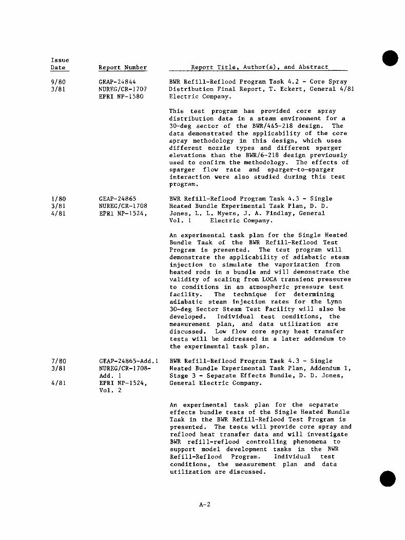
IssueDate
9/803/81
Report Number
GEAP-24844 NUREG/CR-1707 EPRI NP-1580
Report Title, Author(s), and Abstract
1/803/814/81
GEAP-24865 NUREG/CR-1708 EPRI NP-1524,
7/803/81
4/81
GEAP-24865-Add.1 NUREG/CR-1708- Add. 1EPRI NP-1524, Vol. 2
BWR Refill-Reflood Program Task 4.2 - Core Spray Distribution Final Report, T. Eckert, General 4/81 Electric Company.
This test program has provided core spray distribution data in a steam environment for a 30-deg sector of the BWR/4&5-218 design. The data demonstrated the applicability of the core spray methodology in this design, which uses different nozzle types and different sparger elevations than the BWR/6-218 design previously used to confirm the methodology. The effects of sparger flow rate and sparger-to-sparger interaction were also studied during this test program.
BWR Refill-Reflood Program Task 4.3 - Single Heated Bundle Experimental Task Plan, D. D.Jones, L. L. Myers, J. A. Findlay, General Vol. 1 Electric Company.
An experimental task plan for the Single Heated Bundle Task of the BWR Ref ill-Ref lood Test Program is presented. The test program will demonstrate the applicability of adiabatic steam injection to simulate the vaporization from heated rods in a bundle and will demonstrate the validity of scaling from LOCA transient pressures to conditions in an atmospheric pressure test facility. The technique for determining adiabatic steam injection rates for the Lynn 30-deg Sector Steam Test Facility will also be developed. Individual test conditions, the measurement plan, and data utilization are discussed. Low flow core spray heat transfer tests will be addressed in a later addendum to the experimental task plan.
BWR Refill-Reflood Program Task 4.3 - Single Heated Bundle Experimental Task Plan, Addendum 1, Stage 3 - Separate Effects Bundle, D. D. Jones, General Electric Company.
An experimental task plan for the separate effects bundle tests of the Single Heated Bundle Task in the BWR Ref ill-Ref lood Test Program is presented. The tests will provide core spray and reflood heat transfer data and will investigate BWR refill-reflood controlling phenomena to support model development tasks in the BWR Refill-Reflood Program. Individual test conditions, the measurement plan and data utilization are discussed.
A-2
IssueDate
8/824/838/83
Report Number
GEAP-24936 NUREG/CR-2001 EPRI NP-2372
4/817/819/81
GEAP-24893 NUREG/CR-1846 EPRI NP-1525, Vol. 1
_____ Report Title, Author(s), and Abstract_____
BWR Refill-Reflood Program, Task 4.3 - Single Heated Bundle Final Report, W. A. Sutherland,J. E. Barton, J. A. Findlay, General Electric Gompany.
Separate effects and system response tests conducted in the Single Heated Bundle (SHB) facility have produced data for evaluating: (a)low flow core spray heat transfer; (b) bundle bottom reflood heat transfer; (c) channel to bypass heat transfer, and (d) BWR refill-reflood controlling phenomena. These data support model development and qualification.
Transient Loss of Coolant Accident (LOCA) experiments conducted in the SHB test facility have demonstrated that an adiabatic bundle system, using steam injection to simulate vaporization, simulates the thermal-hydraulic system response of a heated bundle system. These tests which were conducted by subjecting the adiabatic bundle and than an electrically heated bundle to the same LOCA transients, confirm the application of the adiabatic steam injection technique to a large-scale test facility.
BWR Refill-Reflood Program Task 4.4 - CCFL/Refill System Effects Tests (30 Sector) - Experimental Task Plan, D. G. Schumacher, General Electric Gompany.
An experimental task plan for the CCFL/Refill system effects tests (30 Sector) of the BWR Refill-Reflood program is presented. The CCFL/Refill system effects tests will provide separate effect and BWR system response data for a large scale sector test facility (30 SSTF) for use in LOCA best-estimate model assessment.
Contained in the document is a definition of: the experimental task objectives, required modification to the existing 30° SSTF, test parameters and ranges, individual test categories, measurement plan approach, and data utilization.
A-3
IssueDate
4/819/81
12/81
Report Number
GEAP-24893-1 NUREG/CR-1846, Add. AEPRI NP-1525, Vol. 2
_____ Report Title, Author(s), and Abstract_____
BWR Refill-Reflood Program Task 4.4 - CCFL/Refill System Effects Tests (30° Sector) - Experimental Task Plan, Addendum A, SSTF CCFL/Refill Shake- down Plan, D. C. Schumacher, T. Eckert, General Electric Company.
This Addendum A to the CCFL/Refill System Effects Tests (30° Sector) Experimental Task Plan presents a definition of the approach and strategy to be followed in shakedown of the 30 sector facility. Specified in the document are equipment performance tests, an initial set of facility counter-current flow-limiting (CCFL) tests, and predictions of selected facility phenomena.
4/819/81
12/81
CEAP-24893-2 NUREG/CR-1846, Add. BEPRI NP-1525, Vol. 3
BWR Refill-Reflood Program Task 4.4 - CCFL/Refill System Effects Tests (30 Sector) - Experimental Task Plan, Addendum B, 30° SSTF CCFL/Refill Separate Effect Test Plan, D. G. Schumacher, General Electric Company.
Addendum B to the 30 SSTF Experimental Task Plan Document defines test operating techniques and specific test conditions to be utilized in the separate effect test series conducted as part of the 30° SSTF CCFL/Refill test program.
Seven sets of separate-effeet tests are planned for the CCFL/Refill test program addressing:
a. multiple bundle CCFL characteristics,b. combined bundle and bypass CCFL
characteristics,c. upper plenum ECCS mixing performance,d. channel wall and fuel bundle leakage heat
transfer characteristics,e. bypass mixing characteristics,f. jet pump/core steam flow split
characteristics, andg. simplified blowdown characteristics of the
test vessel.
6/811/82
12/81
GEAP-24893-3 NUREG/CR-1846, Add. CEPRI NP-1525, Vol. 4
BWR Refill-Reflood Program Task 4.4 - CCFL/Refill System Effects Tests (30 Sector) - Experimental Task Plan, Addendum C, 30° SSTF CCFL/Refill BWR/6 System Response Test Plan, D. G. Schumacher General Electric Company.
Addendum C to the 30 Steam Sector Test Facility (30° SSTF) Experimental Task Plan defines the objectives, specific test conditions, and summarized test operating procedures for the
A-4
IssueDate Report Number
9/811/82
8/82
6/815/829/82
GEAP-2A893-4 NUREG/CR-18A6, Add. DEPRI NP-1525, Vol. 5
GEAP-2A939 NUREG/CR-2133 EPRI NP-158A
_____ Report Title, Author(s), and Abstract_____
transient loss-of-coolant accident (LOCA) simulation tests performed in the 30 SSTF under the BWR Refill-Reflood Program.
BWR Refill-Reflood Program Task A.A - CCFL/Refill System Effects Tests (30° Sector) - Experimental Task Plan, Addendum D, SSTF CCFL/Refill with ECCS Variation Test Plan (BWR/A ECCS Geometry),D. C. Schumacher, General Electric Company.
Addendum D to the 30° Sector Experimenta,l Task Plan provides definition of objectives, specific test conditions, and summarized test operating procedures for separate effect and system tests performed in the 30 Steam Sector Test Facility (30 SSTF) with lower pressure coolant injection (LPCI) location and low pressure core spray (LPCS) geometry representative of BWR/A configuration.
BWR Refill-Reflood Program Task A.A - 30° SSTF Description Document, J. E. Barton, D. C. Schumacher, J. A. Findlay, S. C. Caruso, General Electric Company.
A description of the 30° Steam Sector Test Facility (SSTF) is provided. The purpose of this large scale facility is to provide BWR separate effect and system response data for use in LOCA best estimate model assessment. This document contains descriptions of: the design objectives,the scaling bases for the system and components, the test section and supporting test loop, the measurement system, the data acquisition and reduction systems, and the operating procedures.
3/82 CEAP-220AA11/82 NUREC/CR-25668/83 EPRI NP-2373
BWR Refill-Reflood Program Task A.A - CCFL/Refill System Effects Tests (30° Sector) - Evaluation of Parallel Channel Phenomena, J. A. Findlay, General Electric Company.
This report interprets the results from SSTF separate effects tests and system response tests and evaluates the parallel channel flow phenomena.
Parallel channel flow of interest occurs when there is a level in the lower plenum which allows redistribution of steam to the channel inlet orifices. Parallel channel effects are evidenced by three different flow regimes that may occur simultaneously. These regimes, identified from
SSTF tests, are: (1) counter-current flow, (2)co-current upflow, and (3) liquid downflow.
A-5

IssueDate
3/824/838/83
Report Number
GEAP-22046 NUREG/CR-2568 EPRI NP-2374
12/826/838/83
GEAP-22I5G NUREG/CR-2786 EPRI NP-2542
_____ Report Title, Author(s), and Abstract_____
BWR Refill-Reflood Program Task 4.4 - CCFL/Refill System Effects Tests (30° Sector) - SSTF System Response Test Results, D. G. Schumacher, T. Eckert, J. A. Findlay, General Electric Company.
Transient Loss of Coolant Accident (LOCA) experiments conducted in the Steam Sector Test Facility have addressed multidimensional system refill-reflood phenomena. Tests conducted over a pressure domain from 150 psia to ambient pressure have investigated Emergency Core Cooling Systems (ECCS) combinations and injection location, recirculation line break area, initial system mass (i.e. at the start of ECCS injection), and ECCS liquid temperature. Specially scaled tests were also conducted for system phenomena tieback to one-dimensional LOCA simulation experiments.
Test results demonstrate beneficial multidimensional effects leading to early refill and reflood. The system reflood performance is insensitive to variation in initial system mass, break area, and ECCS temperature. Variation in ECCS combinations and injection location effect the distribution of mass and energy within the system, as well as the system reflood rate.
BWR Refill-Reflood Program Task 4.4 - CCFL/Refill System Effects Tests (30° Sector) - Evaluationof ECCS Mixing Phenomena, J. A. Electric Company.
Findlay, General
Experiments addressing thermal hydraulic phenomena under Loss-of-Coolant-Accident conditions have been conducted in a full scale 30 degree sector mock-up of the BWR. The test program included both steady pressure and transient LOCA simulation, at system pressure up to ten atmospheres, and addressed both specific thermal hydraulic phenomena and system response under blowdown/refill/reflood conditions. Mixing and condensation effects observed in these experiments are found to make an important contribution to effective system refill/reflood performance. Principal areas of interest are core spray injection leading to localized subcooling In the upper plenum that breaks down counter-current flow limiting at the top of the core, bypass mixing of subcooled ECCS injection and channel wall heat transfer, and low pressure coolant injection leading to subcooling in the lower plenum that reduces liquid flow out the jet pumps. These effects augment plenum refill and core reflood. Other condensing effects identified and evaluated are evidenced by the coupling of upper plenum two-phase level with
A-6
IssueDate Report Number
3/819/8112/81
GEAP-24932 NUREG/CR-2057 EPRI NP-1526
5/8112/812/83
GEAP-24941 NUREG/CR-2135 EPRI NP-1583
_____ Report Title, Author(s), and Abstract_____
core spray injection location, and subcooled side entry orifice CCFL. Condensation effects do not lead to system performance instability or oscillation, and phenomena are consistent between the System Response Tests and the Separate Effects Tests.
BWR Refill-Reflood Program Task 4.7 - Model Development Task Plan, J. C. M. Andersen,B. S. Shiralkar, General Electric Company.
The development of a boiling water reactor (BWR) version of the TRAC computer code requires the development of models for phenomena of particular importance for the BWR and of models for the specific BWR components. Phenomena of particular importance for the BWR include void-fraction prediction governed by the wall friction, interface shear, the phase and velocity profiles, and the prediction of wall and interface heat transfer. Specific BWR components include the jet pump, steam separator, and steam dryer.
The development of a BWR version of TRAC, furthermore, includes improvements to the basic equations and the code efficiency, and the development of a single channel version.
The tasks in this development are described, and schedules and milestones are given.
BWR Refill-Reflood Program Task 4.7 - TRAC/BWR Component Development, M. M. Aburomia, General Electric Company.
This report describes the development of boiling water reactor (BWR) components that are necessary for the structuring of a best-estimate version of TRAC-BWR. These components are: the jet pumps,the steam separators, and the steam dryers. The component models satisfy their functional specifications and are in accordance with the Transient Reactor Analysis Code (TRAC) basic equations, numerics, and constitutive relations.
The jet pump is developed from the TRAC TEE component. It is structured for both the Drift Flux - ID and the Two-Fluid - I D TRAC versions. The model was run in steady-state and transient operation covering all jet pump flow regimes. The results are in general agreement with experimental data. The steam separators and the steam dryers are structured as integral parts of the pressure vessel. The steam separator model
A-7
IssueDate Report Number
12/8111/821/83
GEAP-24940 NUREG/CR-2134 EPRI NP-1582
4/839/8310/83
GEAP-22051 NUREG/CR-2573 EPRI NP-2375
_____ Report Title, Author(s), and Abstract_____
utilizes an overall flow resistance scheme to separate the phases and achieve the correct pressure drop. The steam dryer model is simulated as a flow resistance to the steam flow, and the model is tailored to give the pressure drop within the dryer.
BWR Refill-Reflood Program Task 4.7 - Constitutive Correlations for Shear and Heat Transfer for the BWR version of TRAC, J. G. M Andersen, K. H. Chu, General Electric Company.
TRAC (Transient Reactor Analysis Code) is a computer code for best estimate analysis of the hydraulic conditions in a reactor system. The constitutive correlations for shear and heat transfer in the boiling water reactor (BWR) version of TRAC are described.
A new model, that accounts for the effect of phase and velocity profiles, has been developed for the interfacial shear and a new set of constitutive correlations are derived. Improvements have been made to the heat transfer in the area of subcooled boiling, boiling transition, and thermal radiation.
BWR Refill-Reflood Program Task 4.7 - Model Development: Basic Models for the BWR Version ofTRAC, J. G. M. Andersen, K. H. Chu, J. C. Shaug, General Electric Company.
TRAC (Transient Reactor Analysis Code) is a computer code for best estimate analysis of the thermal hydraulic conditions in a reactor system. The constitutive correlations for shear and heat transfer developed for the Boiling Water Reactor (BWR) version of TRAC are described.
A universal flow regime map has been developed to tie the regimes for shear and the heat transfer into a consistent package. New models in the areas of interfacial shear, interfacial heat transfer and thermal radiation have been introduced. Improvements have also been made to the constitutive correlations and the numerical methods. All the models have been implemented into the GE version TRACB02 and extensively tested against data.
A-f
IssueDate
4/839/8310/83
Report Number
GEAP-22052 NUREG/CR-2574 EPRI NP-2376
1/818/8110/81
GEAP-24898 NUREG/CR-1899 EPRI NP-1527
7/8310/8311/83
GEAP-22049 NUREG/CR-2571 EPRI NP-2377
_____ Report Title, Author(s), and Abstract_____
BWR Refill-Reflood Program Task 4.7 - Model Development: TRAC-BWR Component Models, Y. K.Cheung, V. Parameswaran, J. C. Shaug, General Electric Company.
TRAC (Transient Reactor Analysis Code) is a computer code for the best estimate analysis for the thermal hydraulic conditions in a reactor system. The development and assessment of the BWR component models developed under the Refill/Reflood Program that are necessary to structure a BWR-version of TRAC are described in this report. These component models are the jet pump, steam separator, steam dryer, two-phase level tracking model and upper plenum mixing model. These models have been implemented into TRAC-B02. Also a single channel option has been developed for individual fuel channel analysis following a system response calculation.
BWR Refill-Reflood Program Task 4.8 - Model Qualification Task Plan, J. A. Findlay,C. L. Sozzi, General Electric Company.
A model qualification task plan for the BWR LOCA best estimate models is presented. The primary objective of this task is to assess the capacity of thermal hydraulic and core heat transfer methods for realistic predictions of component and system behavior under BWR LOCA-ECCS conditions. The secondary objectives are to evaluate data for their applicability to BWR simulation and to determine the relative importance of relevant BWR LOCA-ECCS phenomena. This task is organized into eight plan elements which are: determinegoverning phenomena, identify data base, qualify facilities, put data into usable form, classify data, preliminary assessment of models, develop acceptance criteria, and final qualification of models.
BWR Refill-Reflood Program Task 4.8 - TRAC-BWR Model Qualification Final Report, Md. Alamgir, General Electric Company.
The calculational capability and analytical models of TRACB02 (a best estimate BWR thermal-hyraulic code) are rigorously tested by performing assessment analysis for twelve separate effects and system effects experiments. These experiments cover a broad range of phenomena observed in several simulated-reactor test facilities and, in one case, a BWR power plant. Comparisons of analyses and experimental data are made for separate effects tests (i.e..
A-9

IssueDate Report Number Report Title, Author(s), and Abstract_____
tests with most boundary conditions controlled as independent parameters) of two simple vessel blowdowns, two post-dryout bundle heat-ups, and three multi-dimensional mixing and parallel channel flows. Comparisons are then made for system response tests (i.e., tests showing system transient response to an initiating event) of a one-bundle simulation of a BWR system (the Two-Loop Test Apparatus, TLTA), a 58-bundle simulation of a BWR system (the Steam Sector Test Facility, SSTF) and an actual BWR power plant (Peach Bottom-2).
These assessment calculations indicate that TRACB02 correctly predicts governing phenomena and key events observed in these experiments. The analytical models for shear and heat transfer and the phenomenological models for critical flow, two-phase level tracking and upper plenum mixing were found to realistically represent the measured LOCA responses. Models refinements required for more accurate calculation and identified in this report are water packing, interfacial condensation heat transfer, film boiling heat transfer for large mass flux, entrainment from a two-phase level into a small opening and donor-celling near a subcooled interface.
A-10

APPENDIX B
BWP REFILL/REFLOOD PROGRAM TASK 4.5
360° UPPER PLENUM TESTS
J. Ashjaee
March 1982
B-1
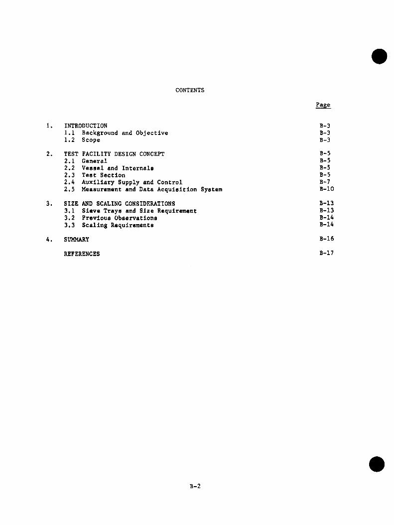
CONTENTS
Page
1. INTRODUCTION B-31.1 Background and Objective B-31.2 Scope B-3
2. TEST FACILITY DESIGN CONCEPT B-52.1 General B-52.2 Vessel and Internals B-52.3 Test Section B-52.4 A ux ilia ry Supply and Control B-72.5 Measurement and Data Acquisition System B-10
3. SIZE AND SCALING CONSIDERATIONS B-133.1 Sieve Trays and Size Requirement B-133.2 Previous Observations B-143.3 Scaling Requirements B-14
4. SUMMARY B-16
REFERENCES B-17
B-2
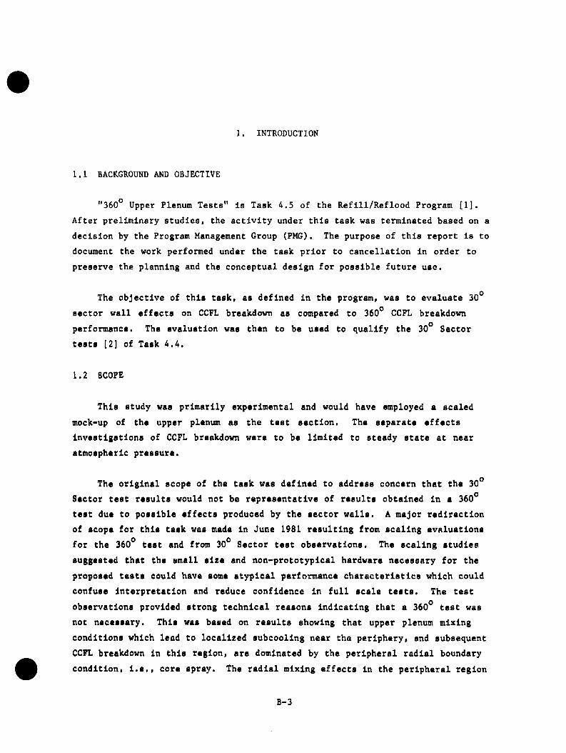
1. INTRODUCTION
1.1 BACKGROUND AND OBJECTIVE
"360° Upper Plenum Tests" is Task 4.5 of the R e fill/R eflo o d Program [1 ]. A fter prelim inary studies, the a c t iv ity under th is task was terminated based on a
decision by the Program Management Group (PMG). The purpose of th is report is to
document the work performed under the task p rio r to cancellation in order to
preserve the planning and the conceptual design fo r possible future use.
The objective of th is task, as defined in the program, was to evaluate 30°
sector w all effects on CCFL breakdown as compared to 360° CCFL breakdown
performance. The evaluation was then to be used to qualify the 30° Sector
tests [2] of Task 4 .4 .
1.2 SCOPE
This study was prim arily experimental and would have employed a scaled
mock-up of the upper plenum as the test section. The separate effects investigations of CCFL breakdown were to be lim ited to steady state at near atmospheric pressure.
The o rig in a l scope of the task was defined to address concern that the 30°
Sector test results would not be representative of results obtained In a 360° test due to possible effects produced by the sector w alls . A major red irection
of scope for th is task was made In June 1981 resulting from scaling evaluations
for the 360° test and from 30° Sector test observations. The scaling studies
suggested that the small size and non-prototyplcal hardware necessary for the
proposed tests could have some atyp ica l performance characteristics which could
confuse In terpretation and reduce confidence In f u l l scale tes ts . The test
observations provided strong technical reasons Indicating that a 360° test was
not necessary. This was based on results showing that upper plenum mixing
conditions which lead to localized subcooling near the periphery, and subsequent CCFL breakdovm In th is region, are dominated by the peripheral rad ia l boundary
condition, I . e . , core spray. The ra d ia l mixing effects In the peripheral region
B-3
therefore dominate any circumferential or wall effects. The scope was then reduced to include only a conceptual design and preliminary size and scaling requirements for a 360° Upper Plenum test apparatus.
B-4
2. TEST FACILITY DESIGN CONCEPT
2.1 GENERAL
The 360° Upper Plenum Test Facility was planned to be built in Lynn, Massachusetts, where the existing 30° Sector test facility, SSTF, is located. The conceptual design developed for the test apparatus uses as much as practicable of the SSTF[3]. A new vessel and new internals would have, been needed, but auxiliary supply and control systems as well as the data acquisition system of the SSTF would have been modified to fit the new requirements.
2.2 VESSEL AND INTERNALS
The test vessel and its internal regions are shown schematically in Figure 1. The vessel is 6 ft. (1.83 m) in diameter and approximately 14-16 ft. (4.3-4.9m) high. The following major internal regions can be identified within the test vessel;
1. Upper Plenum2. Channels3. Standpipes and Steam Dome4. Lower Plenum
The wall of the vessel represents the shroud wall in the BWR/6. Since tests were to be performed at near atmospheric pressure, no additional pressure containing vessel was needed outside the test section as was previously required for the SSTF.
2.3 TEST SECTION
The upper plenum and its boundaries comprise the test section. The steam flow from the core enters the test section through the upper tieplates. The radial distribution of steam flux would be representative of the BWR.
B-5

VENT
STEAM DOME
FEEDBACK STEAM
STANDPIPES
UPPER PLENUMVIEW — WINDOWS
DRAIN
CORE SPRAY HEADER
UPPER TIEPLATE
CORE SUPPORT PLATE
CORE STEAM HEADERS
NORMAL LEVEL LOWER PLENUM
30° SECTOR
50° DRAIN
Figure 1. 360-degree Vessel and Internal Regions
B-6
The core region, about 62 inches (1.6m) in diameter, consists of 188 channels shown diagramatically in Figure 2. Each channel has a dimension of 3.9 inches (99 mm) square.
The upper plenum would be designed with removable 30° sector walls. A30° sector covers about 8 full channels and portions of 16 other channels. Core steam flow to partial channels would be split so that the appropriate amounts are injected on either side of the 30° sector wall. The arrangement selected for the 30° sector (i.e., the orientation of the sector walls with respect to channel walls) resembles that of the SSTF most closely.
As shown in Figure 1, only one EGG line to the vessel was planned. The EGGheader would reside about 6 inches (152 mm) above the upper tieplate level. Theupper plenum vertical height would be approximately 2 ft. (610 mm).
The ECCS header mockup would have a total of approximately 120 nozzles, being divisible by 12 so that the 30° sector has a proportionate number of nozzles. The nozzle design would not be prototypical since new dimensions would require new aiming and spray pattern evaluations. Provisions would be made for test section flow visualization by Including view ports into the upper plenum as shown in Figure 1.
2.4 AUXILIARY SUPPLY AND CONTROL SYSTEM
The auxiliary Supply Systems include the EGG water and the core steam supplies. Figure 3 shows a schematic of the supply, recirculation and drain lines.
The steam supply source is the same as that used in SSTF. The core steam flow to each channel would be controlled using flow limiting orifice to obtain the same reference core radial distribution as was used for SSTF. A "feedwater" steam supply to the vessel, into the steam dome, would be provided to avoid drawing air from the vent line back into the vessel for certain flow conditions.
The drainage flow from the channels would discharge from pipes into the lower plenum. Most of the tests were planned to be run with the lower plenum liquid level above the channel discharge elevation so as to minimize core steam flow interaction between channels. Note that two separate suction lines, as well
B-7
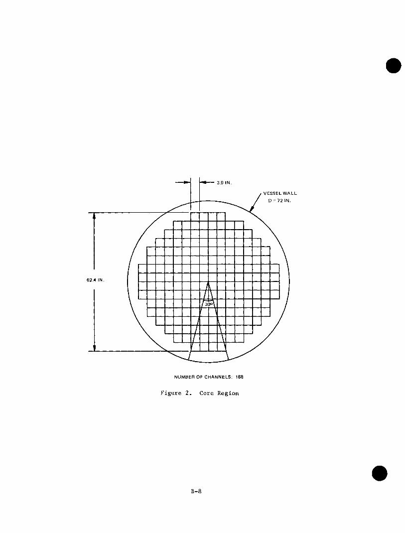
3.9 IN.
VESSEL WALL
D = 72 IN.
62.4 IN.
NUMBER OF CHANNELS: 188
Figure 2. Core Region
B-8
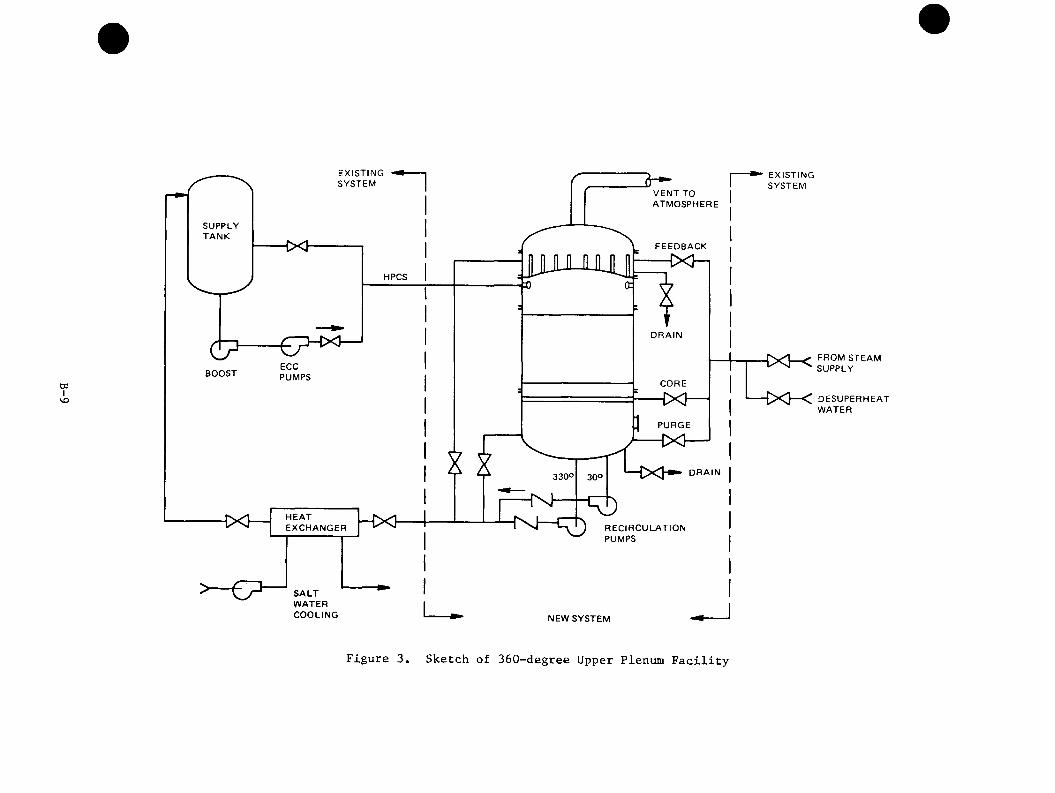
wI
VO
EXISTINGSYSTEM
EXISTINGSYSTEM3
VENT TO ATMOSPHERE
SUPPLYTANK
FEEDBACK
—IXHHPCS
DRAIN
CXl-ECCPUMPSBOOST
CORE
PURGE
DRAIN330°
HEATEXCHANGER —{X} RECIRCULATION
PUMPS
SALTWATERCOOLING NEW SYSTEM
FROM STEAM SUPPLY
DESUPERHEATWATER
Figure 3. Sketch of 360-degree Upper Plenum Facility
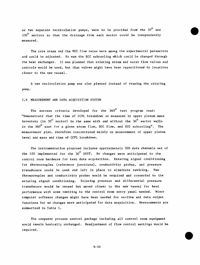
as two separate recirculation pumps, were to be provided from the 30° and 330° sectors so that the drainage from each sector could be independently measured.
The core steam and the ECC flow rates were among the experimental parameters and could be adjusted. So was the ECC subcooling which could be changed through the heat exchanger. It was planned that existing steam and water flow valves and controls would be used, but that valves might have been repositioned to locations closer to the new vessel.
A new recirculation pump was also planned instead of reusing the existingpump.
2.5 MEASUREMENT AND DATA ACQUISITION SYSTEM
The success criteria developed for the 360° test program read: "Demonstrate that the time of CCFL breakdown as measured by upper plenum mass inventory (in 30° sector) is the same with and without the 30° sector walls in the 360° test for a given steam flow, ECC flow, and ECC subcooling". The measurement plan, therefore concentrated mainly on measurement of upper plenum level and mass and time of CCFL breakdown.
The instrumentation proposed includes approximately 300 data channels out of the 450 implemented for the 30° SSTF. No changes were anticipated to the control room hardware for test data acquisition. Existing signal conditioning for thermocouples (reference junctions), conductivity probes, and pressure transducers could be used and left in place to eliminate rewiring. New thermocouples and conductivity probes would be required and connected to the existing signal conditioning. Existing pressure and differential pressure transducers would be reused but moved closer to the new vessel for best performance with some rewiring to the control room entry panel needed. Minor computer software changes might have been needed for on-line and data output functions but no changes were anticipated for data acquisition. Measurements are summarized in Table 1.
The computer process control package including all control room equipment would remain basically unchanged. Readjustment of flow control settings would be required.
B-10
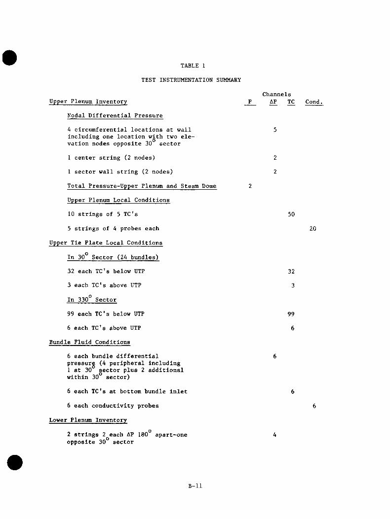
TABLE 1
TEST INSTRUMENTATION SUMMARY
Upper Plenum Inventory
Nodal Differential Pressure
A circumferential locations at wall including one location with two elevation nodes opposite 30 sector
1 center string (2 nodes)
I sector wall string (2 nodes)
Total Pressure-Upper Plenum and Steam Dome
Upper Plenum Local Conditions
10 strings of 5 TC's
5 strings of A probes each
Upper Tie Plate Local Conditions
In 30° Sector (2A bundles)
32 each TC's below UTP
3 each TC's above UTP
In 330° Sector
99 each TC's below UTP
6 each TC's above UTP
Bundle Fluid Conditions
6 each bundle differential pressure (A peripheral including 1 at 30 sector plus 2 additional within 30° sector)
6 each TC's at bottom bundle inlet
6 each conductivity probes
Lower Plenum Inventory
Channels AP TC
50
32
3
99
6
Cond.
20
2 strings 2 each AP 180 apart-one opposite 30 sector
B-11
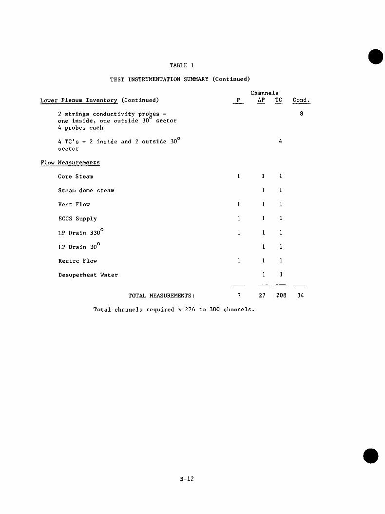
TABLE 1
TEST INSTRUMENTATION SUMMARY (Continued)
Lower Plenum Inventory (Continued)
?. strings conductivity probes - one inside, one outside 30 sector4 probes each
4 TC's sector
2 inside and 2 outside 30
Flow Measurements
Core Steam
Steam dome steam
Vent Flow
ECCS Supply
LP Drain 330°
LP Drain 30°
Recirc Flow
Desuperheat Water
Channels AP TC Cond.
TOTAL MEASUREMENTS: 7 27 208 34
Total channels required 2 7 6 to 300 channels.
B-12
3. SIZE AND SCALING CONSIDERATIONS
3.1 SIEVE TRAYS AND SIZE REQUIREMENT
A major concern in scaling the test section for this task is the possibility of introduction of non-representative phenomena into the test results. Specifically, as a result of experiments in sieve trays and oscillating columns, it has been suggested that the scaled test section, or its 30° sector, may be susceptible to oscillating behaviors that appear in small sieve trays while such motions are unlikely to occur in the full scale BWR.
The oscillatory motions in sieve trays have been typically observed below one m (' 3 ft) diameter [4]. The sieve tray experimental data, however, cannot be directly extended to reactor environment because the media (air-water instead of steam water), the pressure, the gas velocity, and the geometry effects are not sufficiently correlated in the exiting sieve tray results*, and also because some phenomenological differences exist between the two experiments. For one, the processes of condensation and ECC/steam jets interaction have no counterparts in distillations columns. For another, communication below the perforated plate is nearly restricted in the case of the 360° test by the presence of channels. In addition, each bundle would also be partially baffled from its neighbors above the restriction by the fuel channel extension above the surface of each upper tieplate. Baffles above the restrictions have been shown to effectively damp wave motion on otherwise unstable sieve trays.
Therefore, although sieve tray experiments exhibit CCFL characteristics and some resemblance to the BWR upper plenum, a minimum size constraint cannot be deduced from that technology.
*The observed oscillations in sieve trays seem to belong to the classical sloshing motion of liquids in open containers. Such motions are not restricted to a certain size container, but they require different excitation frequencies for different size containers. This is. Indeed, what one may deduce from sieve tray results.
B-13

3.2 PREVIOUS OBSERVATIONS
Examination of flow visualization tests in GE's 16° sector facility [2] confirms lack of periodic sloshing motions or intermittent weeping, and underlines the significance of condensation/flow jets interaction phenomena in creating the chaotic upper plenum flow field in the presence of core sprays.
In the peripheral region, the ECC water flows down and inward under its initial momentum and condenses steam through its subcooling content. Moving inward, the spray momentum and subcooling rapidly dissipates and the flow of the two phase mixture of (ECC) water and (core) steam becomes growingly upward.The upper region of the mixture flows out (rapidly) towards the ECC spargers proximity where condensation is most effective. The result is a quasi recirculating flow field that promotes CCFL breakdown in the peripheral channels.
There is no apparent reason that the presence of the sector walls, or their lack, can have but negligible impacts on this process. in the SSTF tests [5], immediate peripheral upper tieplate subcooling was observed with rapid CCFL breakdown in all of the peripheral bundles, including those next to the sector walls. These results indicate that the radial mixing effects in the peripheral region dominate any wall effects.
3.3 SCALING REQUIREMENTS
A summary of the scaling and required flows is presented in Table 2. The ECC flow rate is scaled proportional to core areas. The maximum core steam required is then determined from CCFL calculations such that the drainage flow was limited to 70% of the ECC flow rate (to allow for buildup of level in the upper plenum). The total steam required includes feedback steam to the upper plenum from above the separators such that there is enough total steam to heat all the ECC water to saturation temperature.
An operating pressure of 20 psia was used in the CCFL calculations; furthermore, it was assumed that the CCFL characteristics of the upper tieplate remain unchanged with proper scaling. It should be pointed out that the available steam supply at Lynn would allow operation at pressures up to about 30 psia with the selected test vessel size, i.e., I.D. = 6 ft (1.83 m).
B-14
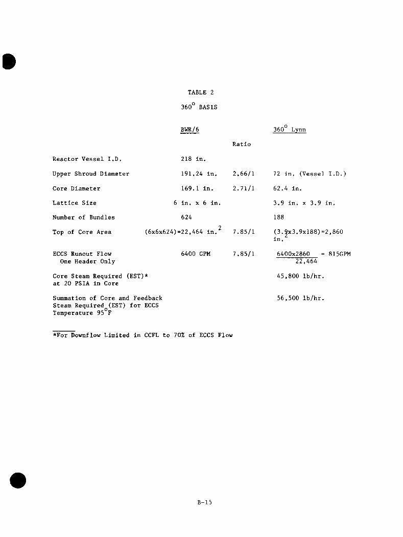
TABLE 2
360 BASIS
Reactor Vessel I.D.
Upper Shroud Diameter
Core Diameter
Lattice Size
Number of Bundles
Top of Core Area
ECCS Runout Flow One Header Only
Core Steam Required (EST)* at 20 PSIA in Core
Summation of Core and Feedback Steam Required (EST) for ECCS Temperature 95°F
BWR/6
218 in.
191.24 in.
169.1 in.
6 in. X 6 in.
624
(6x6x624)=22,464 in.^ 7.85/1
360 Lynn
6400 GPM
Ratio
2.66/1
2.71/1
7.85/1
72 in. (Vessel I.D.)
62.4 in.
3.9 in. X 3.9 in.
188
(3.^x3.9xl88)=2,860in.
6400x2860 = 815GPM22,464
45,800 lb/hr.
56,500 lb/hr.
*For Downflow Limited in CCFL to 70% of ECCS Flow
B-15

4. SUMMARY
A conceptual design and preliminary size and scaling requirements have been developed for a 360° Upper Plenum Tests apparatus.
The design is compatible with the auxiliary resources available at Lynn. A test period of about 3 months, including calibration and shakedown was assumed for the test program.
B-16
REFERENCES
1. Burnette, G. W., "BWR Ref111-Reflood Program Task 4.1 Program Plan," Report GEAP-24924, Nuclear Engineering Division, General Electric Company, January 1981.
2. Schumacher, D. G., "CCFL/Reflll System Effects Tests - 30° SectorExperimental Task Plan," Report GEAP-24893, Nuclear Engineering Division, General Electric Company, April 1981.
3. Barton, J. E., et al., "BWR Ref 111/Ref lood Program Task 4.4 - 30° SSTF Description Document," Report GEAP-24939, Nuclear Engineering Division, General Electric Company, June 1981.
4. Blddulph, M. W., and Stephens, D. J., "Oscillating Behavior on Distillation Trays," AlCHE Journal, Vol. 20, No. 1, pp. 60-67, January 1974.
5. Schumacher, D. G. , Eckert, T., and Findlay, J. A., "BWR Ref 111-Ref lood Program Task 4.4 - CCFL/Reflll System Effects Tests - SSTF System Response Test Results," Report GEAP-22046, Nuclear Engineering Division, General Electric Company, March 1982.
B-17