Embed Size (px)
Citation preview

Operating Instructions
Milltronics BW500 and BW500/L
12/2016Edition
Integrators
Bufferzone
8 mm
8 mm
A text area at the top is (big bar) 2-Spaltig, so the text extends upwards! Then adjust the transparent beams according to and while holding the 8 mm distance from text.I think this means that, if you need to add more lines of text, extend the big bar upwards, while maintaining the proper distance from the text.
The lower pane (smal bar, Dokuklasse) must be only single-column!
Ho
rizo
nt
imm
er a
uf
60
mm
Natural Blue dark CoolGray 100%
The image must not touch with the Bufferzone.
Background coolgray 20%, without history
Image should come behind the bar so that the transparency comes to the fore.Do not change the transparency of the bar!
Title page without bleedin RGB
60
mm
Siemens Serif OT, Semibold, 36/30/26 PT, weissAbsatzformat: 01 System 36/30/26 pt
Siemens Sans OT, Bold, 18/15/13 PT, weissAbsatzformat: 02 Produkt 18/15/13 pt
Siemens Sans OT, Bold, 13/11 PT, weissAbsatzformat: 03 Titel 13/11 pt
Siemens Sans OT, Bold, 13 PT, weissAbsatzformat: 04 Dokuklasse 13 pt
Siemens Sans OT, Bold, 11/7,5 pt, weissAbsatzformat: 05 Ausgabe 11/7,5 pt
Siemens Sans OT, Bold, 13 PT, schwarzAbsatzformat: 06 SectorClaim 13 pt
Find any font sizes for the text fields in the Panel "Paragraph styles"!
© Siemens AG 2016
Safety Guidelines
Warning notices must be observed to ensure personal safety as well as that of others, and to protect the product and the connected equipment. These warning notices are accompanied by a clarification of the level of caution to be observed.
Qualified Personnel
This device/system may only be set up and operated in conjunction with this manual. Qualified personnel are only authorized to install and operate this equipment in accordance with established safety practices and standards.
Unit Repair and Excluded Liability:
• The user is responsible for all changes and repairs made to the device by the user or the user’s agent.• All new components are to be provided by Siemens. • Restrict repair to faulty components only. • Do not reuse faulty components.
Warning: Cardboard shipping package provides limited humidity and moisture protection. This product can only function properly and safely if it is correctly transported, stored, installed, set up, operated, and maintained.
This product is intended for use in industrial areas. Operation of this equipment in a residential area may cause interference to several frequency based communications.
Note: Always use product in accordance with specifications.
Copyright Siemens AG 2016. All Rights Reserved Disclaimer of Liability
This document is available in bound version and in electronic version. We encourage users to purchase authorized bound manuals, or to view electronic versions as designed and authored by Siemens. Siemens will not be responsible for the contents of partial or whole reproductions of either bound or electronic versions.
While we have verified the contents of this manual for agreement with the instrumentation described, variations remain possible. Thus we cannot guarantee full agreement. The contents of this manual are regularly reviewed and corrections are included in subsequent editions. We welcome all suggestions for improvement.
Technical data subject to change.
European Authorized Representative
Siemens AG Industry Sector76181 Karlsruhe Deutschland
• For a selection of Siemens level measurement manuals, go to: www. siemens.com/processautomation. Select Products & Systems, then under Process Instrumentation, select Level Measurement. Manual archives can be found on the Support page by product family.
• For a selection of Siemens weighing manuals, go to: www. siemens.com/processautomation. Under Products & Systems, select Weighing and Batching Systems. Manual archives can be found on the Support page by product family.
okjlkjlj ___________________
___________________
___________________
___________________
___________________
___________________
___________________
___________________
___________________
___________________
___________________
___________________
___________________
___________________
___________________
Milltronics
Integrators BW500 and BW500/L
Operating Instructions
12/2016 A5E33482052-AD
Safety Notes 1
The Manual 2
Milltronics BW500 and BW500/L
3
Specifications 4
Installation 5
Start Up 6
Recalibration 7
Operation 8
PID Control 9
Batching 10
Communications 11
Parameters 12
Troubleshooting 13
Certification 14
Appendix A
Siemens AG Division Process Industries and Drives Postfach 48 48 90026 NÜRNBERG GERMANY
Document order number: A5E33482052 Ⓟ 11/2016 Subject to change
Copyright © Siemens AG 2016. All rights reserved
Legal information Warning notice system
This manual contains notices you have to observe in order to ensure your personal safety, as well as to prevent damage to property. The notices referring to your personal safety are highlighted in the manual by a safety alert symbol, notices referring only to property damage have no safety alert symbol. These notices shown below are graded according to the degree of danger.
DANGER indicates that death or severe personal injury will result if proper precautions are not taken.
WARNING indicates that death or severe personal injury may result if proper precautions are not taken.
CAUTION indicates that minor personal injury can result if proper precautions are not taken.
NOTICE indicates that property damage can result if proper precautions are not taken.
If more than one degree of danger is present, the warning notice representing the highest degree of danger will be used. A notice warning of injury to persons with a safety alert symbol may also include a warning relating to property damage.
Qualified Personnel The product/system described in this documentation may be operated only by personnel qualified for the specific task in accordance with the relevant documentation, in particular its warning notices and safety instructions. Qualified personnel are those who, based on their training and experience, are capable of identifying risks and avoiding potential hazards when working with these products/systems.
Proper use of Siemens products Note the following:
WARNING Siemens products may only be used for the applications described in the catalog and in the relevant technical documentation. If products and components from other manufacturers are used, these must be recommended or approved by Siemens. Proper transport, storage, installation, assembly, commissioning, operation and maintenance are required to ensure that the products operate safely and without any problems. The permissible ambient conditions must be complied with. The information in the relevant documentation must be observed.
Trademarks All names identified by ® are registered trademarks of Siemens AG. The remaining trademarks in this publication may be trademarks whose use by third parties for their own purposes could violate the rights of the owner.
Disclaimer of Liability We have reviewed the contents of this publication to ensure consistency with the hardware and software described. Since variance cannot be precluded entirely, we cannot guarantee full consistency. However, the information in this publication is reviewed regularly and any necessary corrections are included in subsequent editions.
BW500 and BW500/L Operating Instructions, 12/2016, A5E33482052-AD 3
Table of contents
1 Safety Notes ......................................................................................................................................... 11
2 The Manual ........................................................................................................................................... 13
3 Milltronics BW500 and BW500/L ........................................................................................................... 15
4 Specifications ........................................................................................................................................ 17
5 Installation ............................................................................................................................................ 21
5.1 Dimensions ............................................................................................................................. 21
5.2 Layout ..................................................................................................................................... 23
5.3 Optional Plug-ins ..................................................................................................................... 25 5.3.1 SmartLinx Module ................................................................................................................... 25 5.3.2 mA I/O board ........................................................................................................................... 25 5.3.3 LVDT Conditioner Card........................................................................................................... 26 5.3.4 Optional Components and their Locations ............................................................................. 27
5.4 Interconnection ....................................................................................................................... 27 5.4.1 System Diagram ..................................................................................................................... 28 5.4.2 Scale - One Load Cell ............................................................................................................. 29 5.4.3 Scale - Two Load Cells ........................................................................................................... 30 5.4.4 Scale - Four Load Cells .......................................................................................................... 32 5.4.5 Scale - Six Load Cells ............................................................................................................. 33 5.4.6 Scale - LVDT ........................................................................................................................... 34
5.5 Speed ...................................................................................................................................... 35 5.5.1 Constant Speed (No Sensor) .................................................................................................. 35 5.5.2 Main Speed Sensor ................................................................................................................ 36 5.5.3 Auxiliary Speed Sensor........................................................................................................... 37
5.6 Auxiliary Inputs ........................................................................................................................ 38
5.7 Auto Zero ................................................................................................................................ 38
5.8 RS232 Port 1 .......................................................................................................................... 39 5.8.1 Printers .................................................................................................................................... 39 5.8.2 Computers and Modems ........................................................................................................ 39
5.9 Remote Totalizer ..................................................................................................................... 40
5.10 mA Output 1 ............................................................................................................................ 40
5.11 Relay Output ........................................................................................................................... 40
5.12 RS485 Port 2 .......................................................................................................................... 41 5.12.1 Daisy Chain ............................................................................................................................. 41 5.12.2 Terminal Device ...................................................................................................................... 41
5.13 RS232 Port 3 .......................................................................................................................... 41
5.14 Power Connections ................................................................................................................. 42
5.15 mA I/O Board Connections ..................................................................................................... 43

Table of contents
BW500 and BW500/L 4 Operating Instructions, 12/2016, A5E33482052-AD
5.16 Installing/replacing the back-up battery ................................................................................. 44
6 Start Up ................................................................................................................................................ 47
6.1 Keypad ................................................................................................................................... 47
6.2 Program Mode ....................................................................................................................... 48 6.2.1 Program Mode Display .......................................................................................................... 48 6.2.2 To enter PROGRAM mode .................................................................................................... 49 6.2.3 RUN Mode ............................................................................................................................. 51
6.3 Initial Start Up ......................................................................................................................... 51 6.3.1 Power Up ............................................................................................................................... 52 6.3.2 Programming .......................................................................................................................... 52
6.4 Load Cell Balancing ............................................................................................................... 57 6.4.1 Typical Two Load cell belt scale ............................................................................................ 58 6.4.1.1 Access P295 .......................................................................................................................... 58 6.4.2 Balancing six load cell belt scales.......................................................................................... 62 6.4.2.1 Balancing for A and B ............................................................................................................ 62 6.4.2.2 Balancing for C and D ............................................................................................................ 62 6.4.3 Zero Calibration...................................................................................................................... 63 6.4.4 RUN Mode ............................................................................................................................. 65
7 Recalibration ......................................................................................................................................... 67
7.1 Belt Speed Compensation ..................................................................................................... 67 7.1.1 Access P018 .......................................................................................................................... 67
7.2 Material Tests ......................................................................................................................... 68 7.2.1 %Change ............................................................................................................................... 69 7.2.1.1 Access P019 and enter EDIT mode ...................................................................................... 70 7.2.2 Material Test .......................................................................................................................... 70
7.3 Design Changes..................................................................................................................... 72
7.4 Recalibration .......................................................................................................................... 72 7.4.1 Routine Zero .......................................................................................................................... 72 7.4.2 Initial Zero .............................................................................................................................. 74 7.4.3 Direct Zero ............................................................................................................................. 75 7.4.4 Auto Zero ............................................................................................................................... 76 7.4.5 Routine Span ......................................................................................................................... 77 7.4.6 Initial Span ............................................................................................................................. 78 7.4.7 Direct Span ............................................................................................................................ 80 7.4.8 Multispan ................................................................................................................................ 81 7.4.8.1 Programming .......................................................................................................................... 82
7.5 Online Calibration................................................................................................................... 85 7.5.1 Online Calibration feature ...................................................................................................... 86 7.5.2 Activate Online Calibration ..................................................................................................... 88
7.6 Factoring ................................................................................................................................ 90 7.6.1 Access P359 in VIEW mode .................................................................................................. 91
7.7 Linearization ........................................................................................................................... 92
8 Operation .............................................................................................................................................. 97
8.1 Load Sensing ......................................................................................................................... 97
Table of contents
BW500 and BW500/L Operating Instructions, 12/2016, A5E33482052-AD 5
8.2 Speed Sensing ........................................................................................................................ 97
8.3 Differential Speed Detection ................................................................................................... 98
8.4 Moisture Compensation .......................................................................................................... 98
8.5 Incline compensation .............................................................................................................. 99
8.6 Modes of Operation .............................................................................................................. 100
8.7 Damping ................................................................................................................................ 100
8.8 mA I/O (0/4-20 mA) ............................................................................................................... 101
8.9 Relay Output ......................................................................................................................... 102
8.10 Totalization ............................................................................................................................ 103 8.10.1 Internal Totalizer ................................................................................................................... 103 8.10.2 External Totalizer .................................................................................................................. 104
9 PID Control ......................................................................................................................................... 107
9.1 Hardware .............................................................................................................................. 107
9.2 Connections .......................................................................................................................... 107 9.2.1 Setpoint Controller – Rate Control ........................................................................................ 108 9.2.2 Setpoint Controller – Load Control ........................................................................................ 109 9.2.3 Setpoint Controller – Master/Slave Control........................................................................... 110 9.2.4 Setpoint Controller – Rate and Load Control ........................................................................ 111
9.3 Setup and Tuning .................................................................................................................. 112 9.3.1 Proportional Control (Gain), P .............................................................................................. 112 9.3.2 Integral Control (Automatic Reset), I .................................................................................... 112 9.3.3 Derivative Control (Pre-Act or Rate), D ................................................................................ 113 9.3.4 Feed Forward Control, F ....................................................................................................... 113
9.4 PID Setup and Tuning........................................................................................................... 114 9.4.1 Initial Start-Up ....................................................................................................................... 114
9.5 Programming ........................................................................................................................ 117
10 Batching ............................................................................................................................................. 121
10.1 Connections .......................................................................................................................... 122 10.1.1 Typical Ladder Logic ............................................................................................................. 122
10.2 Programming ........................................................................................................................ 123
10.3 Operation .............................................................................................................................. 123 10.3.1 Pre-act Function .................................................................................................................... 124
11 Communications ................................................................................................................................. 125
11.1 BW500 and BW500/L and SmartLinx ................................................................................... 125
11.2 Connections .......................................................................................................................... 126 11.2.1 Wiring Guidelines .................................................................................................................. 126
11.3 Configuring Communication Ports ........................................................................................ 127 11.3.1 P770 Serial protocols ............................................................................................................ 127 11.3.2 P771 Protocol address.......................................................................................................... 128 11.3.3 P772 Baud Rate .................................................................................................................... 128 11.3.4 P773 Parity ........................................................................................................................... 128
Table of contents
BW500 and BW500/L 6 Operating Instructions, 12/2016, A5E33482052-AD
11.3.5 P774 Data bits...................................................................................................................... 129 11.3.6 P775 Stop bits ...................................................................................................................... 129 11.3.7 P778 Modem attached ......................................................................................................... 129 11.3.8 P779 Modem idle time ......................................................................................................... 130 11.3.9 P780 RS-232 Transmission interval .................................................................................... 130 11.3.10 P781 Data message ............................................................................................................ 131 11.3.11 P799 Communications Control ............................................................................................ 131
11.4 Dolphin Protocol ................................................................................................................... 132
11.5 Modbus RTU/ASCII Protocol ............................................................................................... 133 11.5.1 How Modbus Works ............................................................................................................. 133 11.5.2 Modbus RTU vs. ASCII ........................................................................................................ 134 11.5.3 Modbus Format .................................................................................................................... 134 11.5.4 Modbus Register Map .......................................................................................................... 134 11.5.5 Modbus Register Map (cont’d) ............................................................................................. 138
11.6 Modems ............................................................................................................................... 147 11.6.1 Example Setup ..................................................................................................................... 147
11.7 Error Handling ...................................................................................................................... 149
12 Parameters .......................................................................................................................................... 153
12.1 Start Up (P001 to P017) ....................................................................................................... 153 12.1.1 P001 Language .................................................................................................................... 153 12.1.2 P002 Test Reference Selection ........................................................................................... 153 12.1.3 P003 Number of Load Cells ................................................................................................. 154 12.1.4 P004 Rate Measurement System ........................................................................................ 154 12.1.5 P005 Design Rate Units ....................................................................................................... 154 12.1.6 P008 Date ............................................................................................................................ 154 12.1.7 P009 Time ............................................................................................................................ 155 12.1.8 P011 Design Rate ................................................................................................................ 155 12.1.9 P014 Design Speed ............................................................................................................. 155 12.1.10 P015 Speed Constant .......................................................................................................... 155 12.1.11 P016 Belt Length.................................................................................................................. 156 12.1.12 P017 Test Load .................................................................................................................... 156 12.1.13 P018 Speed Adjust .............................................................................................................. 157 12.1.14 P019 Manual Span Adjust ................................................................................................... 157 12.1.15 P022 Minimum Speed Frequency ........................................................................................ 157 12.1.16 P080 Display Damping ........................................................................................................ 157 12.1.17 P081 Display Scroll Mode .................................................................................................... 158
12.2 Relay/Alarm Function (P100 - P117) ................................................................................... 158 12.2.1 P100 Relay Function ............................................................................................................ 158 12.2.2 P101 High Alarm / Deviation Alarm ..................................................................................... 159 12.2.3 P102 Low Alarm ................................................................................................................... 159 12.2.4 P107 Relay Alarms .............................................................................................................. 159 12.2.5 P117 Relay Dead Band ....................................................................................................... 160 12.2.6 P118 Relay Logic ................................................................................................................. 160 12.2.7 P119 Override ...................................................................................................................... 160
12.3 mA I/O Parameters (P200 - P220) ....................................................................................... 161 12.3.1 P200 mA Output Range ....................................................................................................... 161 12.3.2 P201 mA Output Function .................................................................................................... 161 12.3.3 P204 mA Output Average .................................................................................................... 161
Table of contents
BW500 and BW500/L Operating Instructions, 12/2016, A5E33482052-AD 7
12.3.4 P212 mA Output Minimum .................................................................................................... 162 12.3.5 P213 mA Output Maximum ................................................................................................... 162 12.3.6 P214 4 mA Output Trim ........................................................................................................ 162 12.3.7 P215 20 mA Output Trim ...................................................................................................... 162 12.3.8 P220 mA Output Damping .................................................................................................... 162 12.3.9 P250 mA input range ............................................................................................................ 163 12.3.10 P255 mA Input Function ....................................................................................................... 163 12.3.11 P261 4 mA Input Trim ........................................................................................................... 163 12.3.12 P262 20 mA Input Trim ......................................................................................................... 164 12.3.13 P270 Auxiliary Input Function ............................................................................................... 165
12.4 Calibration Parameters (P295 – P360) ................................................................................. 167 12.4.1 P295 Load Cell Balancing .................................................................................................... 167 12.4.2 P341 Days Of Service........................................................................................................... 167 12.4.3 P350 Calibration Security ..................................................................................................... 168
12.5 Online Calibration Options (P355 - P358) ............................................................................ 168 12.5.1 P355 Online Calibration Feature .......................................................................................... 168 12.5.2 P356 Online Calibration Reference Weight .......................................................................... 168 12.5.3 P357 Online Calibration Limits ............................................................................................. 169 12.5.4 P358 Online Calibration Activation ....................................................................................... 169 12.5.5 P359 Factoring ...................................................................................................................... 169 12.5.6 P360 Calibration Duration ..................................................................................................... 169 12.5.7 P365 Multispan ..................................................................................................................... 170 12.5.8 P367 Direct Zero Entry ......................................................................................................... 170 12.5.9 P368 Direct Span Entry ........................................................................................................ 170 12.5.10 P370 Zero Limit Deviation % ................................................................................................ 171 12.5.11 P371 Auto Zero Initiation Upper Limit ................................................................................... 171 12.5.12 P377 Initial Zero .................................................................................................................... 171 12.5.13 P388 Initial Span ................................................................................................................... 171
12.6 Linearization Parameters (P390 - P392) .............................................................................. 172 12.6.1 P390 Linearizer ..................................................................................................................... 172 12.6.2 P391 Linearizer Load Points ................................................................................................. 172 12.6.3 P392 Linearizer Compensation % ........................................................................................ 172 12.6.4 P398-01 Moisture Content .................................................................................................... 172 12.6.5 P398-02 Moisture Content .................................................................................................... 172 12.6.6 P399 Incline Sensing ............................................................................................................ 173
12.7 Proportional Integral Derivative (PID) Control ...................................................................... 173 12.7.1 P400 PID System .................................................................................................................. 173 12.7.2 P401 PID Update Time ......................................................................................................... 173 12.7.3 P402 PID Process Value Source .......................................................................................... 174 12.7.4 P405 Proportional Term ........................................................................................................ 174 12.7.5 P406 Integral Term ............................................................................................................... 174 12.7.6 P407 Derivative Term ........................................................................................................... 174 12.7.7 P408 Feed Forward Term ..................................................................................................... 174 12.7.8 P410 Manual Mode Output ................................................................................................... 175 12.7.9 P414 Setpoint Configuration ................................................................................................. 175 12.7.10 P415 Local Set point Value .................................................................................................. 175 12.7.11 P416 External Setpoint ......................................................................................................... 176 12.7.12 P418 Remote Setpoint Ratio ................................................................................................ 176 12.7.13 P419 PID Freeze Option ....................................................................................................... 176
Table of contents
BW500 and BW500/L 8 Operating Instructions, 12/2016, A5E33482052-AD
12.8 Batch Control (P560 – P568) ............................................................................................... 176 12.8.1 P560 Batch Mode Control .................................................................................................... 176 12.8.2 P564 Batch Setpoint ............................................................................................................ 177 12.8.3 P566 Batch Pre-Warn .......................................................................................................... 177 12.8.4 P567 Batch Pre-Warn Setpoint ............................................................................................ 177 12.8.5 P568 Batch Pre-Act ............................................................................................................. 177 12.8.6 P569 Manual Batch Pre-Act Amount ................................................................................... 178 12.8.7 P598 Span Adjust Percentage ............................................................................................. 178
12.9 Totalization (P619 - P648) ................................................................................................... 178 12.9.1 P619 Totaling Dropout ......................................................................................................... 178 12.9.2 P620 Display Zero Dropout .................................................................................................. 178 12.9.3 P621 mA Zero Dropout ........................................................................................................ 179 12.9.4 P631 Totalizer Resolution .................................................................................................... 179 12.9.5 P634 Communication Totalizer Resolution .......................................................................... 180 12.9.6 P635 Verification Totalizer ................................................................................................... 180 12.9.7 P638 External Totalizer Resolution...................................................................................... 181 12.9.8 P643 External Contact Closure ............................................................................................ 182 12.9.9 P647 Totalizer Display ......................................................................................................... 182 12.9.10 P648 Totalizer Reset, Internal ............................................................................................. 182 12.9.11 P680 Test Load: Weight (Options)....................................................................................... 183 12.9.12 P681 Total Mass of Test Weights ........................................................................................ 183 12.9.13 P682 Average Idler Spacing ................................................................................................ 183 12.9.14 P690 Speed Constant Entry ................................................................................................ 183 12.9.15 P691 Drive Pulley Diameter ................................................................................................. 184 12.9.16 P692 Pulses Per Sensor Revolution .................................................................................... 184
12.10 ECal Parameters (P693 – P698) .......................................................................................... 184 12.10.1 P693 Load Cell Capacity Units ............................................................................................ 184 12.10.2 P694 ECal Load Cell Capacity ............................................................................................. 184 12.10.3 P695 ECal Load Cell Sensitivity .......................................................................................... 185 12.10.4 P696 ECal Load Cell Excitation ........................................................................................... 185 12.10.5 P697 ECal Idler Spacing ...................................................................................................... 185 12.10.6 P698 ECal Conveyor Inclination .......................................................................................... 185 12.10.7 P699 ECal mV Span ............................................................................................................ 186 12.10.8 P735 Back Light ................................................................................................................... 186 12.10.9 P739 Time Zone................................................................................................................... 186
12.11 Communication (P740 - P799) ............................................................................................. 187 12.11.1 P742 Word Order Parameter ............................................................................................... 187 12.11.2 P750 – P769 SmartLinx Module Specific Parameters ......................................................... 187 12.11.3 P770 – P789 Local Port Parameters ................................................................................... 187
12.12 SmartLinx Hardware Testing ............................................................................................... 187 12.12.1 P790 Hardware Error ........................................................................................................... 188 12.12.2 P791 Hardware Error Code ................................................................................................. 188 12.12.3 P792 Hardware Error Count ................................................................................................ 188 12.12.4 P794 SmartLinx Module Type .............................................................................................. 188 12.12.5 P795 SmartLinx Protocol ..................................................................................................... 189 12.12.6 P799 Communications Control ............................................................................................ 189
12.13 Test and Diagnostic (P900 - P951) ...................................................................................... 189 12.13.1 P900 Software Revision ....................................................................................................... 189 12.13.2 P901 Memory Test ............................................................................................................... 189
Table of contents
BW500 and BW500/L Operating Instructions, 12/2016, A5E33482052-AD 9
12.13.3 P911 mA Output Test ........................................................................................................... 190 12.13.4 P914 mA Input Value ............................................................................................................ 190 12.13.5 P918 Speed Input Frequency ............................................................................................... 190 12.13.6 P931 Running Totalizer ........................................................................................................ 190 12.13.7 P940 Load Cell mV Signal Test ............................................................................................ 191 12.13.8 P943 Load Cell A/D Reference ............................................................................................. 191 12.13.9 P948 Error Log ...................................................................................................................... 191 12.13.10 P950 Zero Register ............................................................................................................... 191 12.13.11 P951 Span Register .............................................................................................................. 191 12.13.12 P952 Design Load ................................................................................................................ 192 12.13.13 P999 Master Reset ............................................................................................................... 192
13 Troubleshooting .................................................................................................................................. 193
13.1 Generally ............................................................................................................................... 193
13.2 Specifically ............................................................................................................................ 193
14 Certification ......................................................................................................................................... 197
14.1 Certification ........................................................................................................................... 197
14.2 Parameters unlocked when certification switch is set: ......................................................... 197
14.3 Certification Printing .............................................................................................................. 198
A Appendix............................................................................................................................................. 199
A.1 Appendix I ............................................................................................................................. 199 A.1.1 Memory Backup .................................................................................................................... 199 A.1.2 Software Updates ................................................................................................................. 199 A.1.3 Calibration Criteria ................................................................................................................ 199
A.2 Appendix II ............................................................................................................................ 200
A.3 Technical support .................................................................................................................. 205
Glossary ............................................................................................................................................. 207
Index................................................................................................................................................... 211

Table of contents
BW500 and BW500/L 10 Operating Instructions, 12/2016, A5E33482052-AD
BW500 and BW500/L Operating Instructions, 12/2016, A5E33482052-AD 11
Safety Notes 1
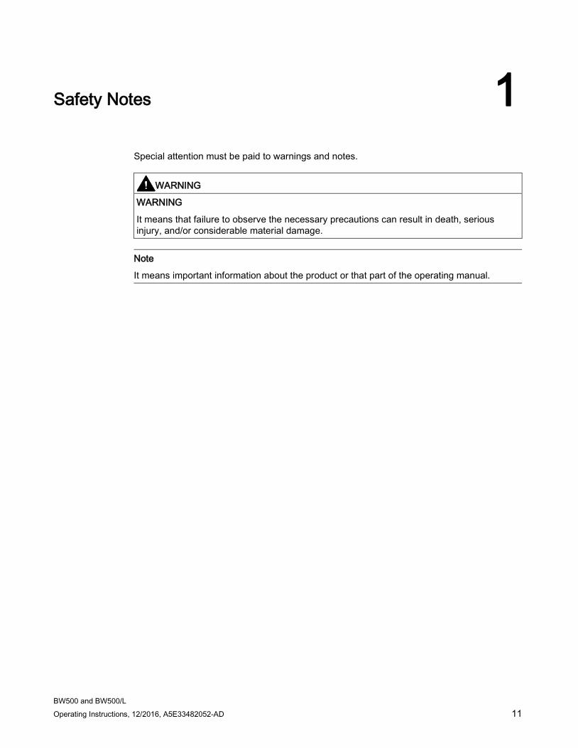
Special attention must be paid to warnings and notes.
WARNING
WARNING
It means that failure to observe the necessary precautions can result in death, serious injury, and/or considerable material damage.
Note
It means important information about the product or that part of the operating manual.

Safety Notes
BW500 and BW500/L 12 Operating Instructions, 12/2016, A5E33482052-AD

BW500 and BW500/L Operating Instructions, 12/2016, A5E33482052-AD 13
The Manual 2
Note • The Milltronics BW500 and BW500/L are to be used only in the manner outlined in this
instruction manual. • These products are intended for use in industrial areas. Operation of this equipment in a
residential area may cause interference to several frequency based communications.
This instruction manual covers the operation, installation, and maintenance of Milltronics BW500 and BW500/L.
Please refer to this manual for proper installation and operation of your BW500 or BW500/L belt scale integrator. As BW500 and BW500/L must be connected to a belt scale, and optionally a speed sensor, refer to their manuals as well.
The manual is designed to help you get the most out of your BW500 and BW500/L, and it provides information on the following: • How to install the unit • Outline diagrams
• How to program the unit • Wiring diagrams
• How to operate the keypad and read the display • Parameter values
• How to do an initial Start Up • Parameter uses
• How to optimize and maintain accurate operation of the unit
• MODBUS register mapping
• Modem configuration
We always welcome suggestions and comments about manual content, design, and accessibility. Please direct your comments to [email protected].
For the complete library of Siemens Milltronics manuals, go to Siemens Milltronics manuals (www.siemens.com/weighing).

The Manual
BW500 and BW500/L 14 Operating Instructions, 12/2016, A5E33482052-AD

BW500 and BW500/L Operating Instructions, 12/2016, A5E33482052-AD 15
Milltronics BW500 and BW500/L 3
Milltronics BW500 The Milltronics BW500 is a full-featured integrator for use with belt scales and weighfeeders. The speed and load signals from the conveyor and scale, respectively, are processed to derive rate of material flow, and totalization. The primary values of speed and load, and the derived values of rate and total are available for display on the local LCD, or as output in the form of analog mA, alarm relay and remote totalization.
Milltronics BW500/L The Milltronics BW500/L is an integrator for use in basic belt scale or weighbelt applications. The speed and load signals from the conveyor and scale, respectively, are processed to derive rate of material flow, and totalization. The BW500/L does not include the advanced feature set for control.
Milltronics BW500 and BW500/L features BW500 and BW500/L support Siemens Milltronics Dolphin Plus software and Modbus protocol on the two RS232 ports and the RS485 port for communication to customer PLC or computer. BW500 and BW500/L also support Siemens SmartLinx for popular industrial communication systems.
Reliable and robust user interface
● multi-field LCD display
● local keypad
Instrumentation I/O BW500 BW500/L
Remote totalizer contacts 2 2 Programmable relays 5 2
Programmable discrete inputs 5 5 mA input 2 for PID1) control
mA output 3: rate, load, speed or PID1) control
1: rate, load, speed
1) The optional mA I/O board is required for 3 outputs: PID control, moisture, and incline compensa-tion.

Milltronics BW500 and BW500/L
BW500 and BW500/L 16 Operating Instructions, 12/2016, A5E33482052-AD
Popular Windows and Industrial communications
● Two RS232 ports
● One RS485 port
Individual port configuration for
● Dolphin Plus
● Modbus ASCII
● Modbus RTU
● Printer
● SmartLinx compatible
Controls and operation functions BW500 BW500/L
Load linearization ✓ ✓ Auto zero ✓ ✓
PID control1) ✓ Batch control ✓
Multispan operation ✓ Moisture compensation1) ✓ fixed Incline compensation1) ✓ fixed
Differential speed detection ✓ Real time clock ✓
1) The optional mA I/O board is required for 3 outputs: PID control, moisture, and incline compensa-tion.
BW500 and BW500/L Operating Instructions, 12/2016, A5E33482052-AD 17
Specifications 4
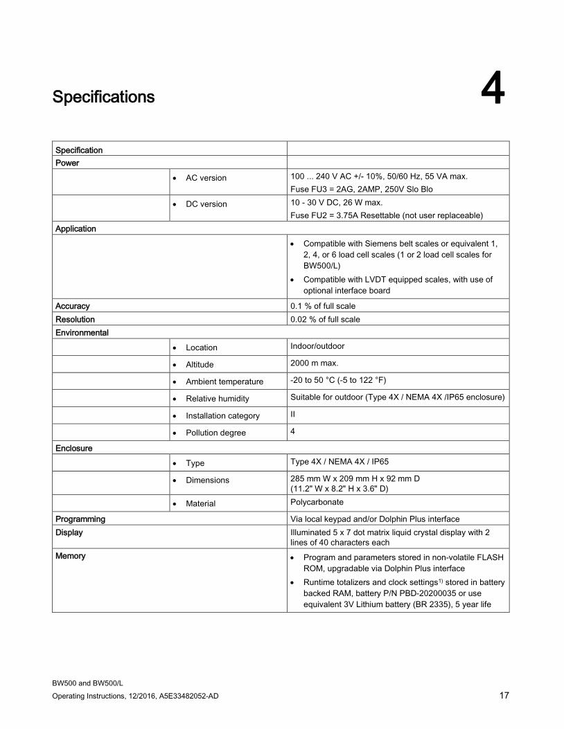
Specification Power • AC version 100 ... 240 V AC +/- 10%, 50/60 Hz, 55 VA max.
Fuse FU3 = 2AG, 2AMP, 250V Slo Blo • DC version 10 - 30 V DC, 26 W max.
Fuse FU2 = 3.75A Resettable (not user replaceable) Application • Compatible with Siemens belt scales or equivalent 1,
2, 4, or 6 load cell scales (1 or 2 load cell scales for BW500/L)
• Compatible with LVDT equipped scales, with use of optional interface board
Accuracy 0.1 % of full scale Resolution 0.02 % of full scale Environmental • Location Indoor/outdoor
• Altitude 2000 m max.
• Ambient temperature -20 to 50 °C (-5 to 122 °F)
• Relative humidity Suitable for outdoor (Type 4X / NEMA 4X /IP65 enclosure)
• Installation category II
• Pollution degree 4
Enclosure • Type Type 4X / NEMA 4X / IP65
• Dimensions 285 mm W x 209 mm H x 92 mm D (11.2" W x 8.2" H x 3.6" D)
• Material Polycarbonate
Programming Via local keypad and/or Dolphin Plus interface Display Illuminated 5 x 7 dot matrix liquid crystal display with 2
lines of 40 characters each Memory • Program and parameters stored in non-volatile FLASH
ROM, upgradable via Dolphin Plus interface • Runtime totalizers and clock settings1) stored in battery
backed RAM, battery P/N PBD-20200035 or use equivalent 3V Lithium battery (BR 2335), 5 year life
Specifications
BW500 and BW500/L 18 Operating Instructions, 12/2016, A5E33482052-AD
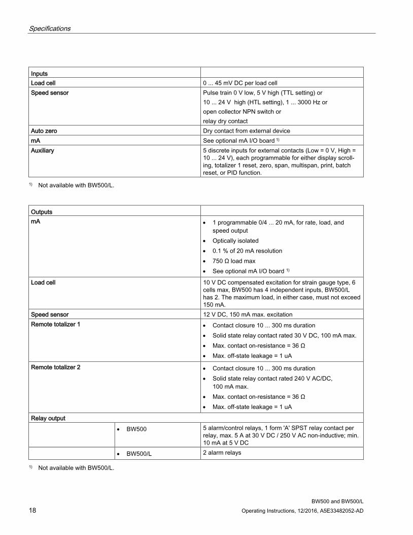
Inputs Load cell 0 ... 45 mV DC per load cell Speed sensor Pulse train 0 V low, 5 V high (TTL setting) or
10 ... 24 V high (HTL setting), 1 ... 3000 Hz or open collector NPN switch or relay dry contact
Auto zero Dry contact from external device mA See optional mA I/O board 1) Auxiliary 5 discrete inputs for external contacts (Low = 0 V, High =
10 ... 24 V), each programmable for either display scroll-ing, totalizer 1 reset, zero, span, multispan, print, batch reset, or PID function.
1) Not available with BW500/L.
Outputs mA • 1 programmable 0/4 ... 20 mA, for rate, load, and
speed output • Optically isolated • 0.1 % of 20 mA resolution • 750 Ω load max • See optional mA I/O board 1)
Load cell 10 V DC compensated excitation for strain gauge type, 6 cells max, BW500 has 4 independent inputs, BW500/L has 2. The maximum load, in either case, must not exceed 150 mA.
Speed sensor 12 V DC, 150 mA max. excitation Remote totalizer 1 • Contact closure 10 ... 300 ms duration
• Solid state relay contact rated 30 V DC, 100 mA max. • Max. contact on-resistance = 36 Ω • Max. off-state leakage = 1 uA
Remote totalizer 2 • Contact closure 10 ... 300 ms duration • Solid state relay contact rated 240 V AC/DC,
100 mA max. • Max. contact on-resistance = 36 Ω • Max. off-state leakage = 1 uA
Relay output • BW500 5 alarm/control relays, 1 form 'A' SPST relay contact per
relay, max. 5 A at 30 V DC / 250 V AC non-inductive; min. 10 mA at 5 V DC
• BW500/L 2 alarm relays
1) Not available with BW500/L.
Specifications
BW500 and BW500/L Operating Instructions, 12/2016, A5E33482052-AD 19
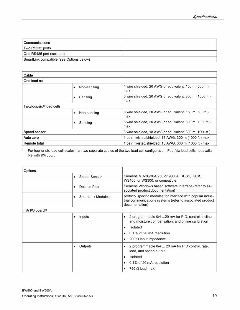
Communications Two RS232 ports One RS485 port (isolated) SmartLinx compatible (see Options below)
Cable One load cell • Non-sensing 4 wire shielded, 20 AWG or equivalent, 150 m (500 ft.)
max. • Sensing 6 wire shielded, 20 AWG or equivalent, 300 m (1000 ft.)
max. Two/four/six1) load cells • Non-sensing 6 wire shielded, 20 AWG or equivalent, 150 m (500 ft.)
max. • Sensing 8 wire shielded, 20 AWG or equivalent, 300 m (1000 ft.)
max. Speed sensor 3 wire shielded, 18 AWG or equivalent, 300 m 1000 ft.) Auto zero 1 pair, twisted/shielded, 18 AWG, 300 m (1000 ft.) max. Remote total 1 pair, twisted/shielded, 18 AWG, 300 m (1000 ft.) max. 1) For four or six load cell scales, run two separate cables of the two load cell configuration. Four/six load cells not availa-
ble with BW500/L.
Options • Speed Sensor Siemens MD-36/36A/256 or 2000A, RBSS, TASS,
WS100, or WS300, or compatible • Dolphin Plus Siemens Windows based software interface (refer to as-
sociated product documentation) • SmartLinx Modules protocol specific modules for interface with popular indus-
trial communications systems (refer to associated product documentation)
mA I/O board1) • Inputs • 2 programmable 0/4 ...20 mA for PID, control, incline,
and moisture compensation, and online calibration • Isolated • 0.1 % of 20 mA resolution • 200 Ω input impedance
• Outputs • 2 programmable 0/4 ... 20 mA for PID control, rate, load, and speed output
• Isolated • 0.1% of 20 mA resolution • 750 Ω load max.
Specifications
BW500 and BW500/L 20 Operating Instructions, 12/2016, A5E33482052-AD
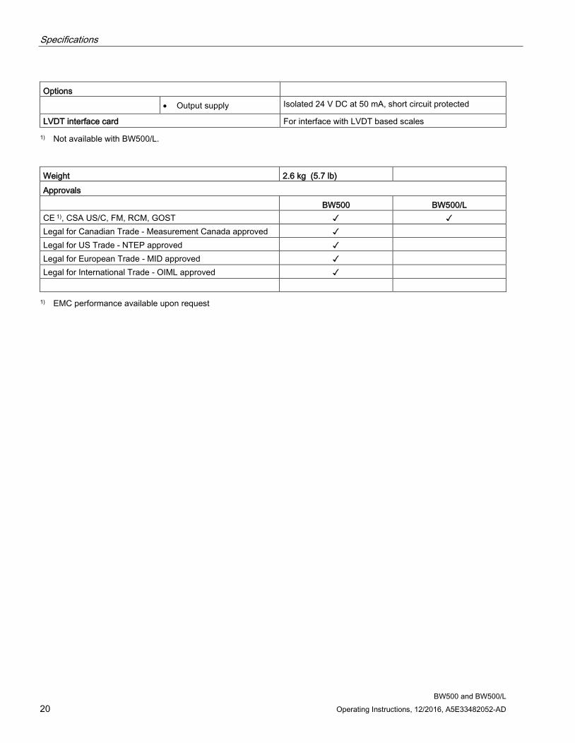
Options • Output supply Isolated 24 V DC at 50 mA, short circuit protected
LVDT interface card For interface with LVDT based scales 1) Not available with BW500/L.
Weight 2.6 kg (5.7 lb) Approvals BW500 BW500/L CE 1), CSA US/C, FM, RCM, GOST ✓ ✓ Legal for Canadian Trade - Measurement Canada approved ✓ Legal for US Trade - NTEP approved ✓ Legal for European Trade - MID approved ✓ Legal for International Trade - OIML approved ✓ 1) EMC performance available upon request
BW500 and BW500/L Operating Instructions, 12/2016, A5E33482052-AD 21
Installation 5
Note • Installation shall only be performed by qualified personnel and in accordance with local
governing regulations. • This product is susceptible to electrostatic shock. Follow proper grounding procedures.
5.1 Dimensions
Note
Nonmetallic enclosure does not provide grounding between connections. Use grounding type bushings and jumpers.
Installation 5.1 Dimensions
BW500 and BW500/L 22 Operating Instructions, 12/2016, A5E33482052-AD
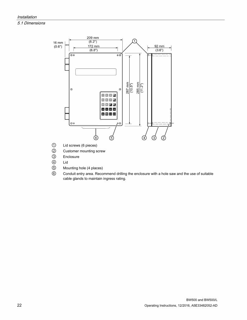
① Lid screws (6 pieces) ② Customer mounting screw ③ Enclosure ④ Lid ⑤ Mounting hole (4 places) ⑥ Conduit entry area. Recommend drilling the enclosure with a hole saw and the use of suitable
cable glands to maintain ingress rating.
Installation 5.2 Layout
BW500 and BW500/L Operating Instructions, 12/2016, A5E33482052-AD 23
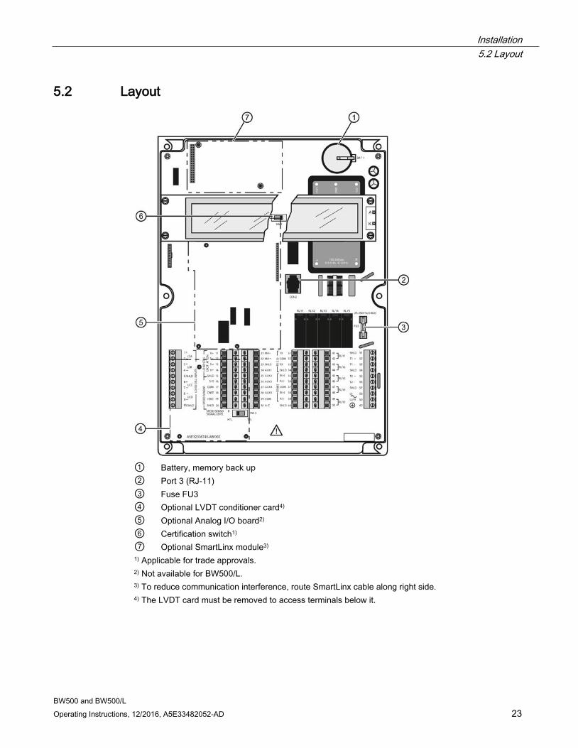
5.2 Layout
① Battery, memory back up ② Port 3 (RJ-11) ③ Fuse FU3 ④ Optional LVDT conditioner card4) ⑤ Optional Analog I/O board2) ⑥ Certification switch1) ⑦ Optional SmartLinx module3) 1) Applicable for trade approvals. 2) Not available for BW500/L. 3) To reduce communication interference, route SmartLinx cable along right side. 4) The LVDT card must be removed to access terminals below it.
Installation 5.2 Layout
BW500 and BW500/L 24 Operating Instructions, 12/2016, A5E33482052-AD
WARNING
• All field wiring must have insulation suitable for at least 250 V. • DC input terminals shall be supplied from a source providing electrical isolation between
the input and output, in order to meet applicable safety requirements of IEC 61010-1. • Relay contact terminals are for use with equipment having no accessible live parts and
wiring having insulation suitable for at least 250 V. The maximum allowable working voltage between adjacent relay contact shall be 250 V.
• The non-metallic enclosure does not provide grounding between conduit connections. Use grounding type bushings and jumpers.
Please note that the DC version of this layout will appear slightly differently.
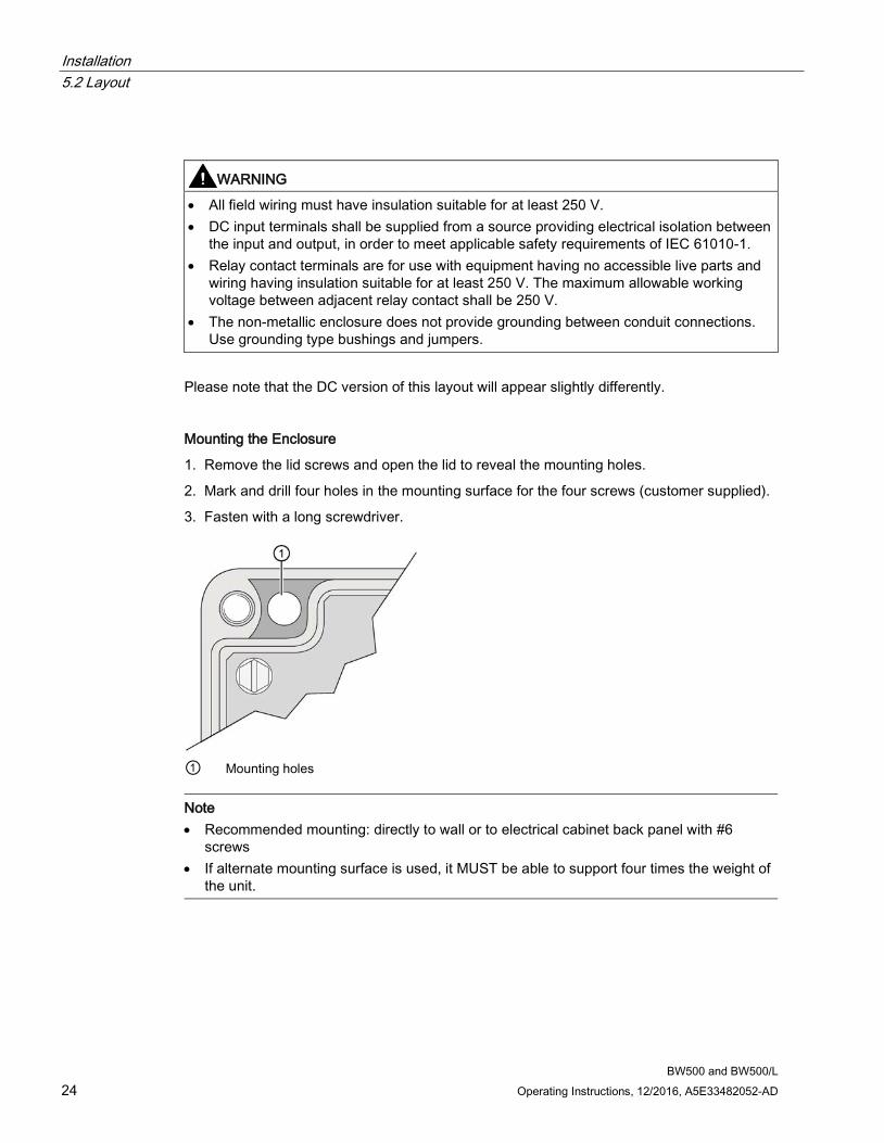
Mounting the Enclosure
1. Remove the lid screws and open the lid to reveal the mounting holes.
2. Mark and drill four holes in the mounting surface for the four screws (customer supplied).
3. Fasten with a long screwdriver.
① Mounting holes
Note • Recommended mounting: directly to wall or to electrical cabinet back panel with #6
screws • If alternate mounting surface is used, it MUST be able to support four times the weight of
the unit.
Installation 5.3 Optional Plug-ins
BW500 and BW500/L Operating Instructions, 12/2016, A5E33482052-AD 25
5.3 Optional Plug-ins
5.3.1 SmartLinx Module BW500 and BW500/L is software/hardware ready to accept the optional Siemens SmartLinx communications module that provides an interface to one of several popular industrial communications systems.
BW500 and BW500/L may be shipped to you without a SmartLinx module, for installation at a later date.
If you are ready to install your SmartLinx module, or want to change it, please follow the instructions as outlined.
Installation
1. Isolate power and voltages applied to the BW500 and BW500/L
2. Open the lid
3. Install the module by mating the connectors and secure in place using the two screws provided
4. Route communication cable to SmartLinx module along the right side of the enclosure wall. This route will reduce communication
Note
Refer to the SmartLinx documentation for any required hardware settings prior to closing the lid.
5. Close the lid.
6. Apply power and voltage to the BW500 and BW500/L.
Refer to
● SmartLinx Module in the Specifications (Page 17)
● P750 – P769 SmartLinx Module Specific Parameters in this manual under Parameters (Page 153)
● the SmartLinx manual for wiring
5.3.2 mA I/O board BW500 is software/hardware ready to accept the optional mA I/O board1). The mA I/O board provides 2 programmable 0/4 to 20 mA outputs, 2 programmable 0/4 to 20 mA inputs and a nominal 24 V DC supply for loop powered devices.
Note
Not available with the BW500/L
Installation 5.3 Optional Plug-ins
BW500 and BW500/L 26 Operating Instructions, 12/2016, A5E33482052-AD
BW500 may be shipped to you without an mA I/O board, for installation at a later date.
If you are ready to install your mA I/O board, please follow the instructions as outlined.
Installation
1. Isolate power and voltages applied to the BW500
2. Open the lid
3. Install the board by mating the connectors and secure the card in place using the three screws provided
4. Close the lid
5. Apply power and voltage to the BW500
Refer to
● Specifications (Page 17)
● mA I/O Board Connections (Page 43)
● mA I/O Parameters (P200 - P220) under mA I/O Parameters (P200 - P220) (Page 161)
● mA I/O (0/4-20 mA) in the mA I/O (0/4-20 mA) (Page 101) section.
5.3.3 LVDT Conditioner Card BW500 is software/hardware ready to accept the optional LVDT conditioner card.
BW500 may be shipped to you without an LVDT conditioner card, for installation at a later date.
If you are ready to install your card, please follow the instructions as outlined.
Installation
1. Isolate power and voltages applied to the BW500
2. Open the lid
3. Install the three provided standoffs into the motherboard at the locations as shown in the diagram in Layout.
4. Connect the wiring between the card and the motherboard according to the instructions in Scale – LVDT.
5. Affix the card on the standoffs using the three screws provided.
6. Close and secure the lid.
7. Re-apply power and voltages to the the BW500.
Refer to
● Specifications (Page 17)
● Scale – LVDT (Page 34)
Installation 5.4 Interconnection
BW500 and BW500/L Operating Instructions, 12/2016, A5E33482052-AD 27
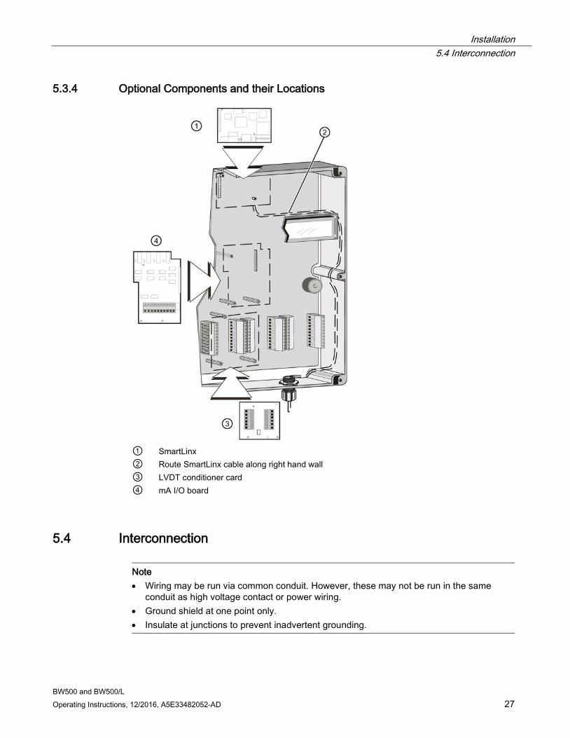
5.3.4 Optional Components and their Locations
① SmartLinx ② Route SmartLinx cable along right hand wall ③ LVDT conditioner card ④ mA I/O board
5.4 Interconnection
Note • Wiring may be run via common conduit. However, these may not be run in the same
conduit as high voltage contact or power wiring. • Ground shield at one point only. • Insulate at junctions to prevent inadvertent grounding.
Installation 5.4 Interconnection
BW500 and BW500/L 28 Operating Instructions, 12/2016, A5E33482052-AD
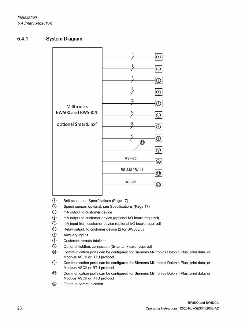
5.4.1 System Diagram
① Belt scale, see Specifications (Page 17) ② Speed sensor, optional, see Specifications (Page 17) ③ mA output to customer device ④ mA output to customer device (optional I/O board required) ⑤ mA input from customer device (optional I/O board required) ⑥ Relay output, to customer device (2 for BW500/L) ⑦ Auxiliary inputs ⑧ Customer remote totalizer ⑨ Optional fieldbus connection (SmartLinx card required) ⑩ Communication ports can be configured for Siemens Milltronics Dolphin Plus, print data, or
Modbus ASCII or RTU protocol ⑪ Communication ports can be configured for Siemens Milltronics Dolphin Plus, print data, or
Modbus ASCII or RTU protocol ⑫ Communication ports can be configured for Siemens Milltronics Dolphin Plus, print data, or
Modbus ASCII or RTU protocol ⑬ Fieldbus communication
Installation 5.4 Interconnection
BW500 and BW500/L Operating Instructions, 12/2016, A5E33482052-AD 29
Note
Typical system capability. Not all components or their maximum quantity may be required.
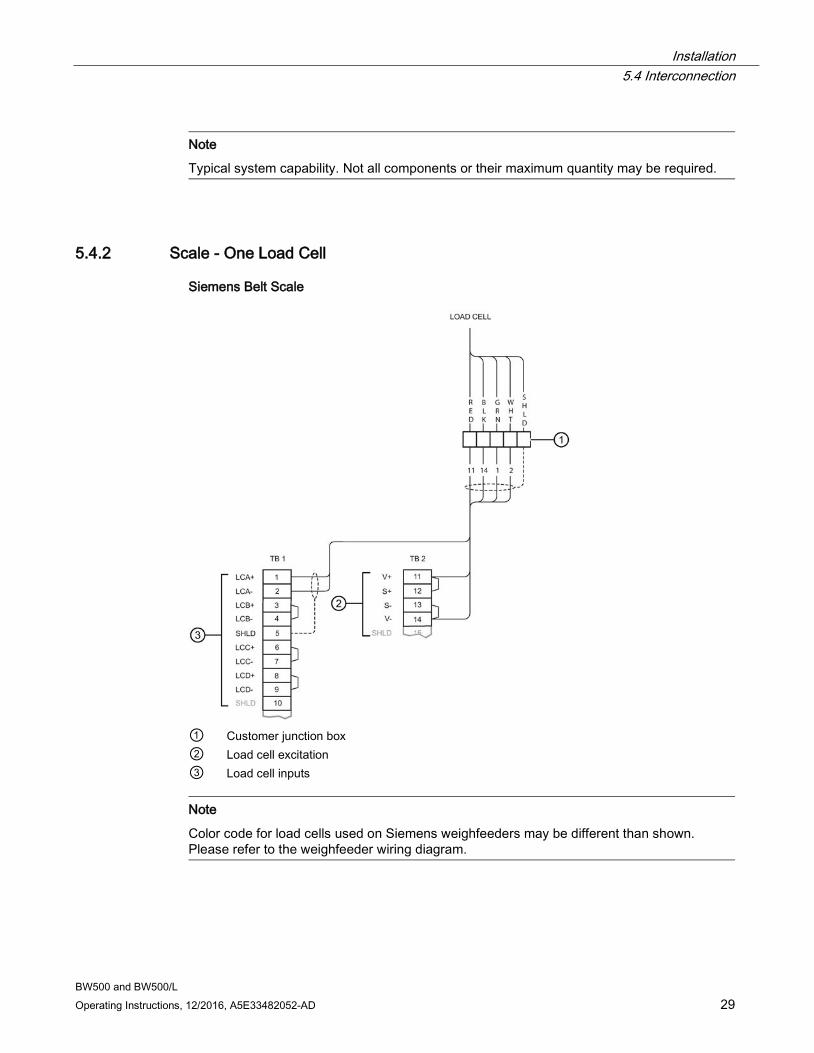
5.4.2 Scale - One Load Cell
Siemens Belt Scale
① Customer junction box ② Load cell excitation ③ Load cell inputs
Note
Color code for load cells used on Siemens weighfeeders may be different than shown. Please refer to the weighfeeder wiring diagram.
Installation 5.4 Interconnection
BW500 and BW500/L 30 Operating Instructions, 12/2016, A5E33482052-AD
Where separation between the BW500 and BW500/L and belt scale exceeds 150 m (500 ft.), or legal for trade certification:
1. Remove jumpers from BW500 and BW500/L terminal 11/12 and 13/14
2. Run additional conductors from: BW500 and BW500/L terminal 12 to scale 'red' BW500 and BW500/L terminal 13 to scale 'blk'
If the load cell wiring colors vary from those shown, or if extra wires are provided, consult Siemens.
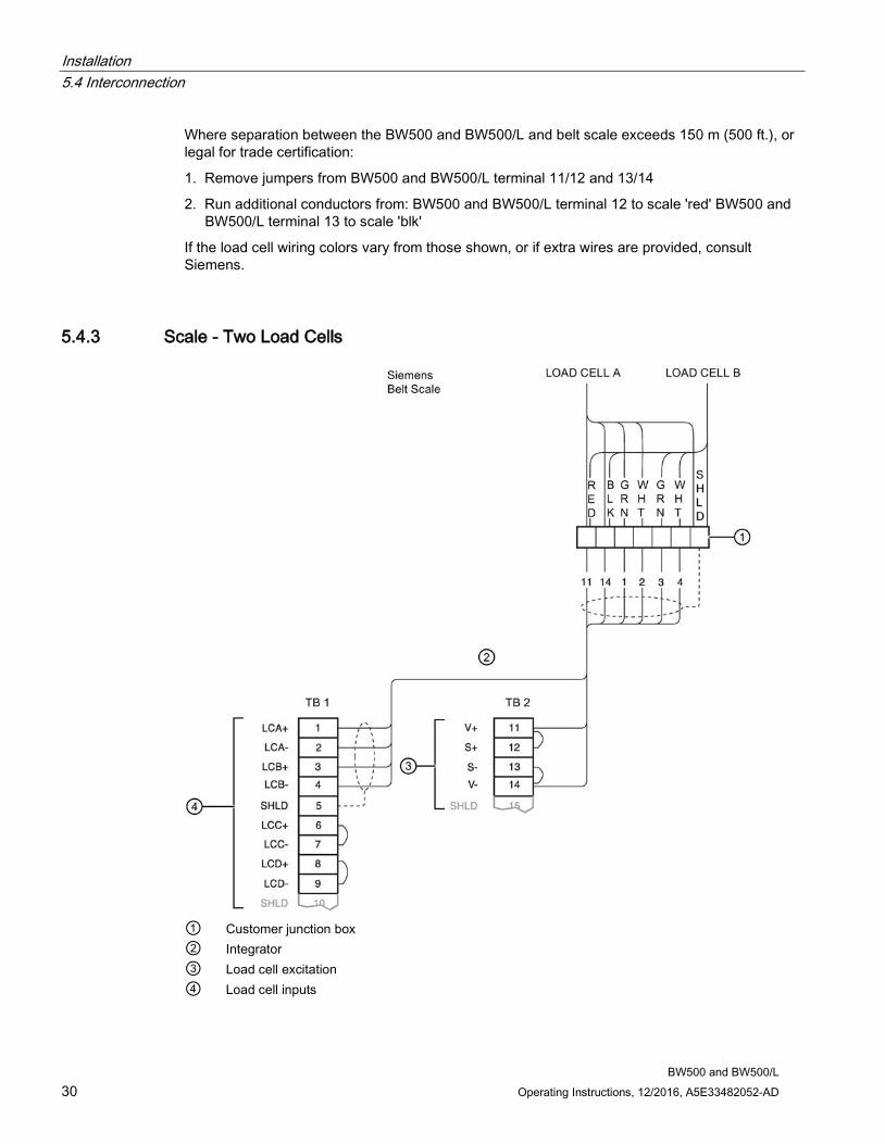
5.4.3 Scale - Two Load Cells
① Customer junction box ② Integrator ③ Load cell excitation ④ Load cell inputs
Installation 5.4 Interconnection
BW500 and BW500/L Operating Instructions, 12/2016, A5E33482052-AD 31
Note
Color code for load cells used on Siemens weighfeeders may be different than shown. Please refer to the weighfeeder wiring diagram.
Where separation between the BW500 and BW500/L and belt scale exceeds 150 m (500 ft.), or legal for trade certification:
1. remove jumpers from BW500 and BW500/L terminal 11/12 and 13/14.
2. run additional conductors from: BW500 and BW500/L terminal 12 to scale 'red' BW500 and BW500/L terminal 13 to scale 'blk'
If the load cell wiring colors vary from those shown, or if extra wires are provided, consult Siemens.
Installation 5.4 Interconnection
BW500 and BW500/L 32 Operating Instructions, 12/2016, A5E33482052-AD
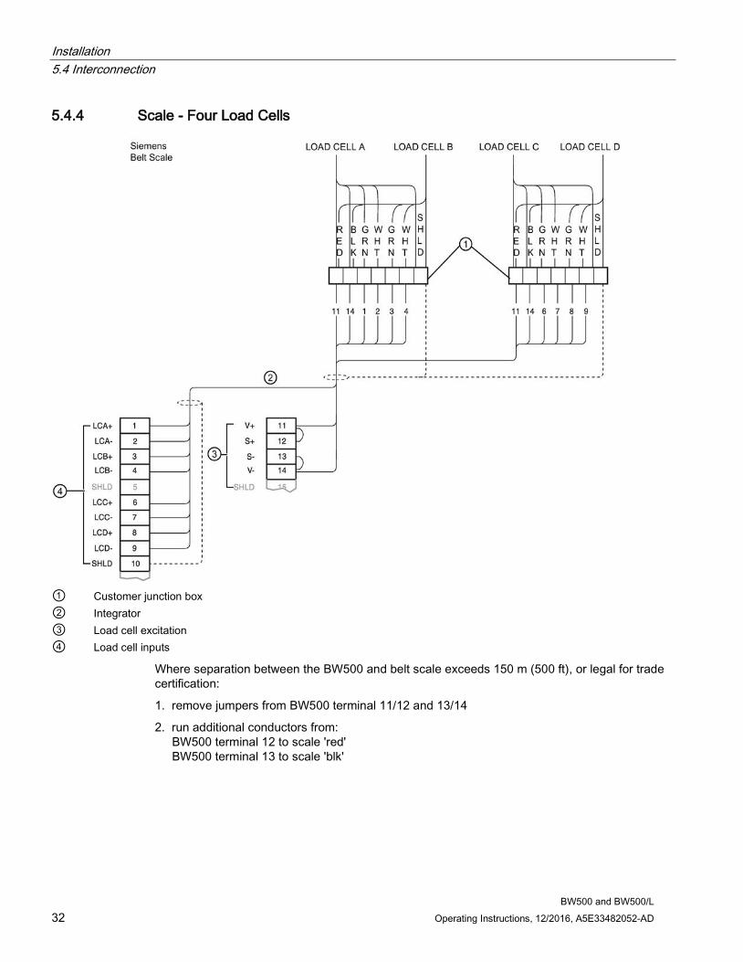
5.4.4 Scale - Four Load Cells
① Customer junction box ② Integrator ③ Load cell excitation ④ Load cell inputs
Where separation between the BW500 and belt scale exceeds 150 m (500 ft), or legal for trade certification:
1. remove jumpers from BW500 terminal 11/12 and 13/14
2. run additional conductors from: BW500 terminal 12 to scale 'red' BW500 terminal 13 to scale 'blk'
Installation 5.4 Interconnection
BW500 and BW500/L Operating Instructions, 12/2016, A5E33482052-AD 33
If the load cell wiring colours vary from those shown, or if extra wires are provided, consult Siemens.
Note
Not available with the BW500/L.
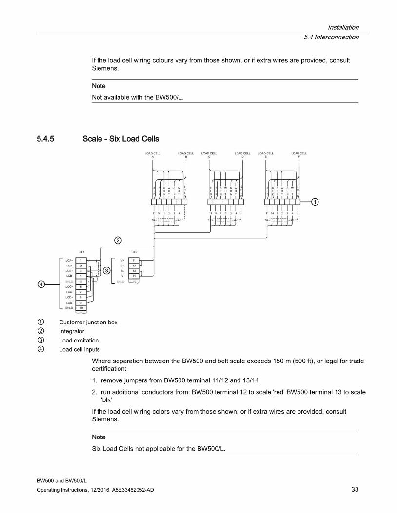
5.4.5 Scale - Six Load Cells
① Customer junction box ② Integrator ③ Load excitation ④ Load cell inputs
Where separation between the BW500 and belt scale exceeds 150 m (500 ft), or legal for trade certification:
1. remove jumpers from BW500 terminal 11/12 and 13/14
2. run additional conductors from: BW500 terminal 12 to scale 'red' BW500 terminal 13 to scale 'blk'
If the load cell wiring colors vary from those shown, or if extra wires are provided, consult Siemens.
Note
Six Load Cells not applicable for the BW500/L.
Installation 5.4 Interconnection
BW500 and BW500/L 34 Operating Instructions, 12/2016, A5E33482052-AD
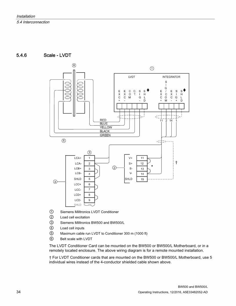
5.4.6 Scale - LVDT
① Siemens Milltronics LVDT Conditioner ② Load cell excitation ③ Siemens Milltronics BW500 and BW500/L ④ Load cell inputs ⑤ Maximum cable run LVDT to Conditioner 300 m (1000 ft) ⑥ Belt scale with LVDT
The LVDT Conditioner Card can be mounted on the BW500 or BW500/L Motherboard, or in a remotely located enclosure. The above wiring diagram is for a remote mounted installation.
† For LVDT Conditioner cards that are mounted on the BW500 or BW500/L Motherboard, use 5 individual wires instead of the 4-conductor shielded cable shown above.
Installation 5.5 Speed
BW500 and BW500/L Operating Instructions, 12/2016, A5E33482052-AD 35
♦ Cable shields must connect to ground only through the BW500 or BW500/L Motherboard (TB15). They should not be grounded to the LVDT Conditioner Card enclosure or any other location.
* Where separation between the BW500 or BW500/L and LVDT conditioner exceeds 150 m (500 ft):
1. remove jumpers from BW500 and BW500/L terminal 11/12 and 13/14
2. run additional conductors from: BW500 terminal 12 to integrator terminal block '+EXC' BW500 terminal 13 to integrator terminal block '-EXC'
Note • LCA (Terminal 2) is jumpered to SHLD (Terminal 5), which internally connects to the load
cell circuit common. • Do not connect to the Speed Sensor (Terminal 17) common, it is isolated from the load
cell circuitry.
5.5 Speed
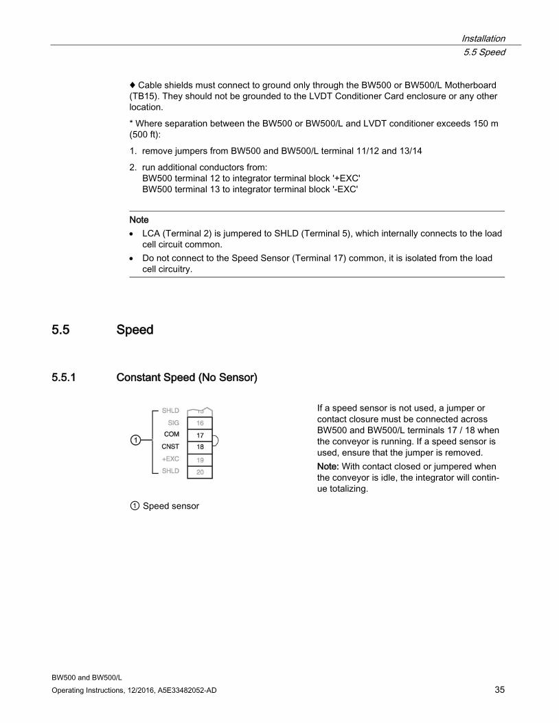
5.5.1 Constant Speed (No Sensor)
If a speed sensor is not used, a jumper or contact closure must be connected across BW500 and BW500/L terminals 17 / 18 when the conveyor is running. If a speed sensor is used, ensure that the jumper is removed. Note: With contact closed or jumpered when the conveyor is idle, the integrator will contin-ue totalizing.
① Speed sensor

Installation 5.5 Speed
BW500 and BW500/L 36 Operating Instructions, 12/2016, A5E33482052-AD
5.5.2 Main Speed Sensor
① Speed sensor ② WS300 example
Note
Shields are common, but not grounded to chassis. Run cable shields through SHLD terminals and ground at BW500 and BW500/L only.
Connect BW500 and BW500/L terminal 16 to speed sensor terminal:
● '2' for clockwise speed sensor shaft rotation
● '3' for counter-clockwise speed sensor shaft rotation.
Speed sensor shaft rotation is viewed from the front cover of the speed sensor enclosure.
Input device in the form of open collector transistor or dry contact across BW500 and BW500/L terminals 16 / 17 will also serve as a suitable speed signal.
If a speed sensor other than the models shown is supplied, consult with Siemens for details.
For the Main Speed Sensor input, switch SW3 should be set to "HTL" for use with speed sensors providing 12V output logic, open-collector NPN outputs or dry contacts. This "HTL" setting provides a switching threshold of 5.5 V (nom.) with +/- 1V hysteresis and an internal pull-up of 12 V through a 3.3 kohm resistor.
To use a speed sensor with 5 V logic-level outputs, the "TTL" setting on SW3 provides a switching threshold of 2.9 V (nom.) with +/- 0.5 V hysteresis and an internal pull-up of 5V (nom.) through a 1.5 kohm resistor.
A second speed sensor input can be added using the Auxiliary inputs: the second speed input allows calculation of Differential Speed. For more information, see Auxiliary Inputs under Parameters (Page 153).
Installation 5.5 Speed
BW500 and BW500/L Operating Instructions, 12/2016, A5E33482052-AD 37
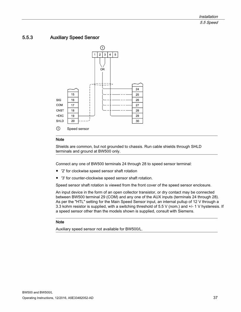
5.5.3 Auxiliary Speed Sensor
① Speed sensor
Note
Shields are common, but not grounded to chassis. Run cable shields through SHLD terminals and ground at BW500 only.
Connect any one of BW500 terminals 24 through 28 to speed sensor terminal:
● '2' for clockwise speed sensor shaft rotation
● '3' for counter-clockwise speed sensor shaft rotation.
Speed sensor shaft rotation is viewed from the front cover of the speed sensor enclosure.
An input device in the form of an open collector transistor, or dry contact may be connected between BW500 terminal 29 (COM) and any one of the AUX inputs (terminals 24 through 28). As per the "HTL" setting for the Main Speed Sensor input, an internal pullup of 12 V through a 3.3 kohm resistor is supplied, with a switching threshold of 5.5 V (nom.) and +/- 1 V hysteresis. If a speed sensor other than the models shown is supplied, consult with Siemens.
Note
Auxiliary speed sensor not available for BW500/L.
Installation 5.6 Auxiliary Inputs
BW500 and BW500/L 38 Operating Instructions, 12/2016, A5E33482052-AD
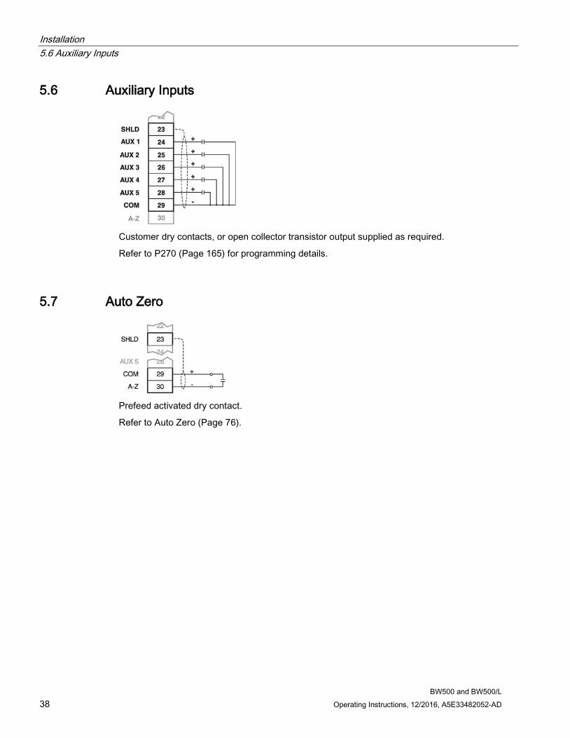
5.6 Auxiliary Inputs
Customer dry contacts, or open collector transistor output supplied as required.
Refer to P270 (Page 165) for programming details.
5.7 Auto Zero
Prefeed activated dry contact.
Refer to Auto Zero (Page 76).
Installation 5.8 RS232 Port 1
BW500 and BW500/L Operating Instructions, 12/2016, A5E33482052-AD 39
5.8 RS232 Port 1
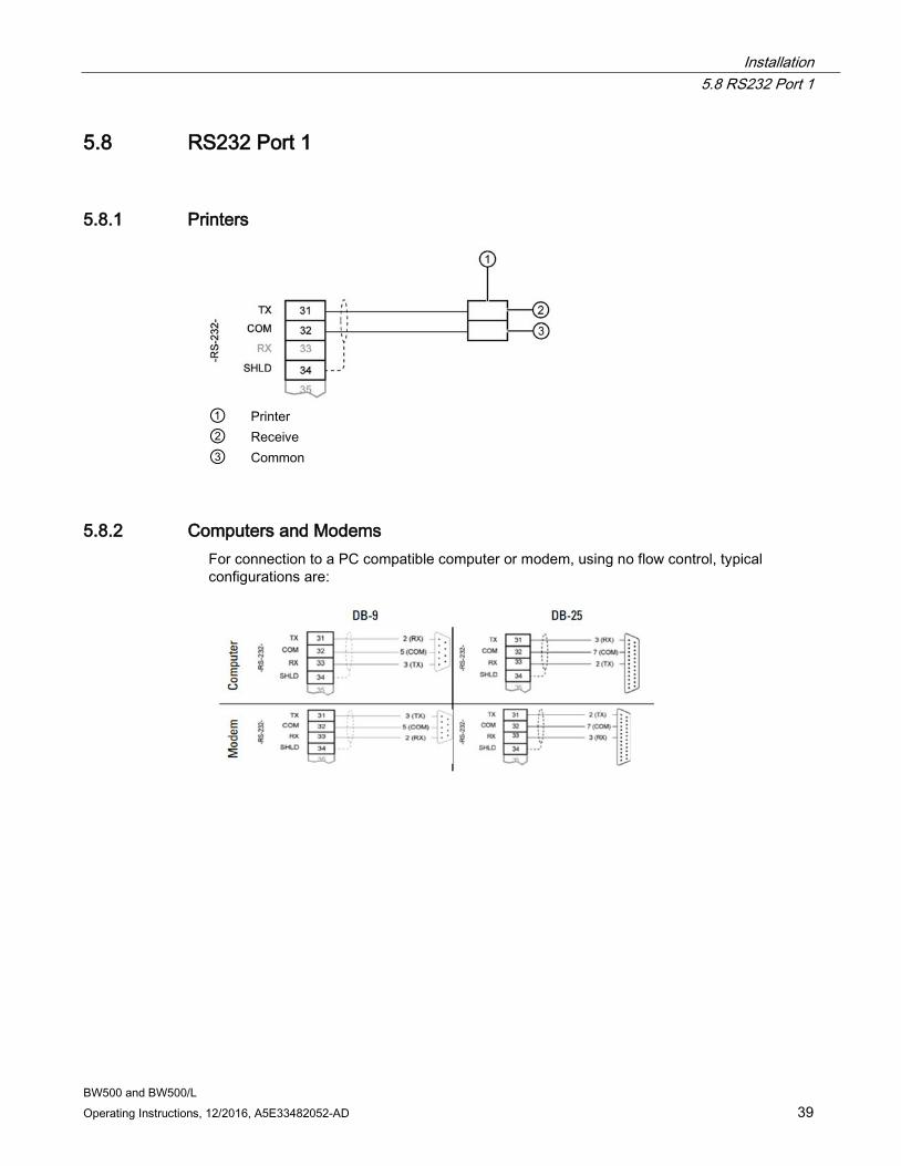
5.8.1 Printers
① Printer ② Receive ③ Common
5.8.2 Computers and Modems For connection to a PC compatible computer or modem, using no flow control, typical configurations are:
Installation 5.9 Remote Totalizer
BW500 and BW500/L 40 Operating Instructions, 12/2016, A5E33482052-AD
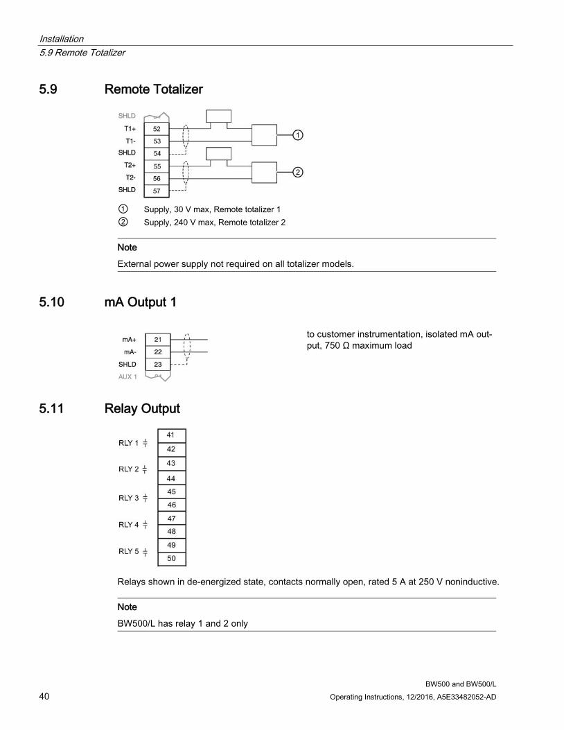
5.9 Remote Totalizer
① Supply, 30 V max, Remote totalizer 1 ② Supply, 240 V max, Remote totalizer 2
Note
External power supply not required on all totalizer models.
5.10 mA Output 1
to customer instrumentation, isolated mA out-put, 750 Ω maximum load
5.11 Relay Output
Relays shown in de-energized state, contacts normally open, rated 5 A at 250 V noninductive.
Note
BW500/L has relay 1 and 2 only
Installation 5.12 RS485 Port 2
BW500 and BW500/L Operating Instructions, 12/2016, A5E33482052-AD 41
5.12 RS485 Port 2
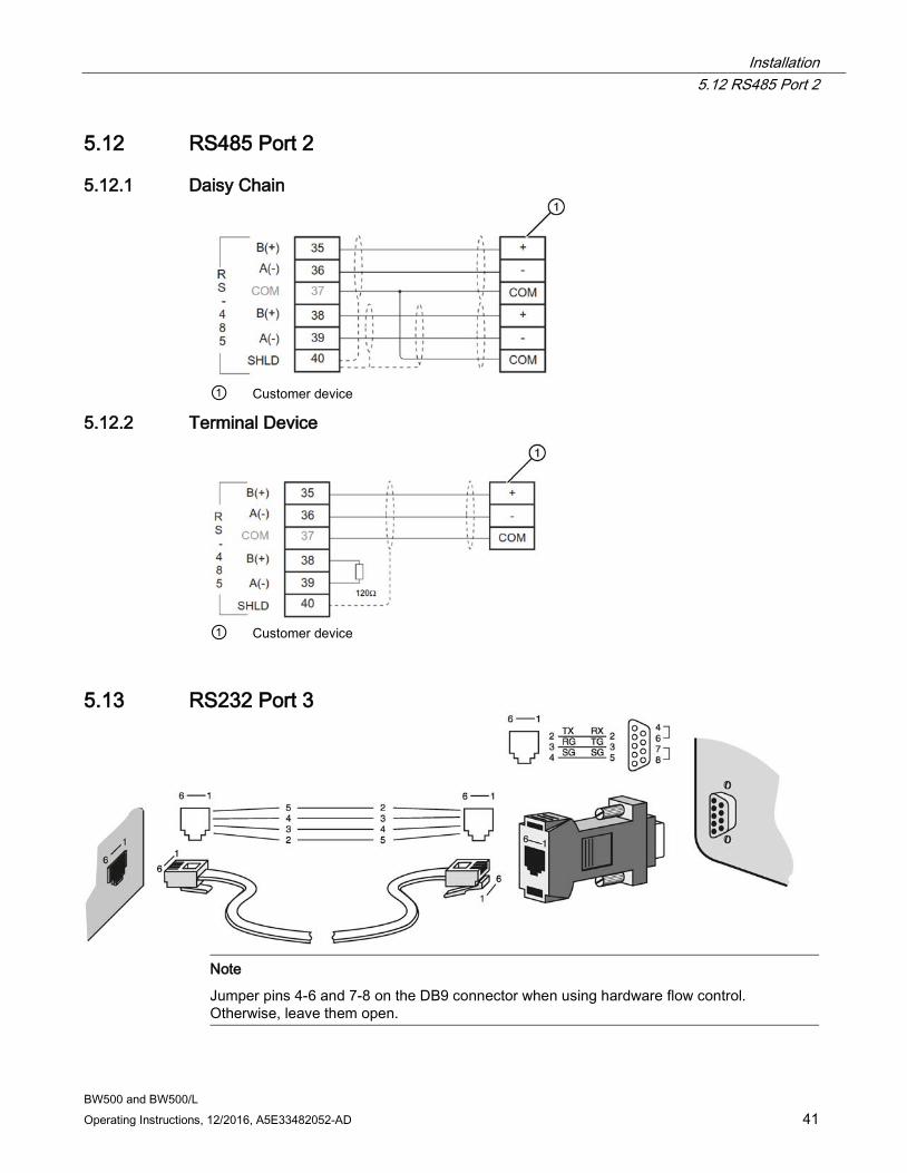
5.12.1 Daisy Chain
① Customer device
5.12.2 Terminal Device
① Customer device
5.13 RS232 Port 3
Note
Jumper pins 4-6 and 7-8 on the DB9 connector when using hardware flow control. Otherwise, leave them open.
Installation 5.14 Power Connections
BW500 and BW500/L 42 Operating Instructions, 12/2016, A5E33482052-AD
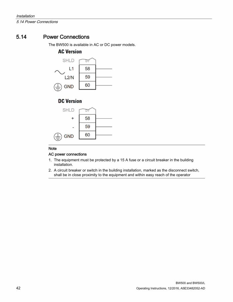
5.14 Power Connections The BW500 is available in AC or DC power models.
Note AC power connections 1. The equipment must be protected by a 15 A fuse or a circuit breaker in the building
installation. 2. A circuit breaker or switch in the building installation, marked as the disconnect switch,
shall be in close proximity to the equipment and within easy reach of the operator
Installation 5.15 mA I/O Board Connections
BW500 and BW500/L Operating Instructions, 12/2016, A5E33482052-AD 43
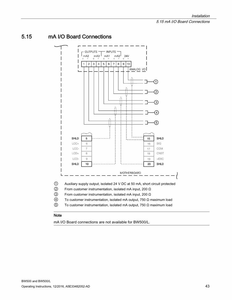
5.15 mA I/O Board Connections
① Auxiliary supply output, isolated 24 V DC at 50 mA, short circuit protected ② From customer instrumentation, isolated mA input, 200 Ω ③ From customer instrumentation, isolated mA input, 200 Ω ④ To customer instrumentation, isolated mA output, 750 Ω maximum load ⑤ To customer instrumentation, isolated mA output, 750 Ω maximum load
Note
mA I/O Board connections are not available for BW500/L.
Installation 5.16 Installing/replacing the back-up battery
BW500 and BW500/L 44 Operating Instructions, 12/2016, A5E33482052-AD
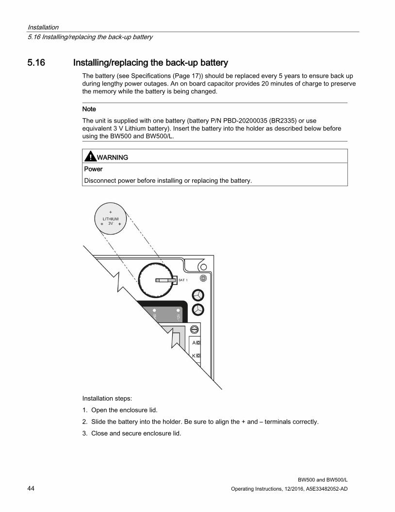
5.16 Installing/replacing the back-up battery The battery (see Specifications (Page 17)) should be replaced every 5 years to ensure back up during lengthy power outages. An on board capacitor provides 20 minutes of charge to preserve the memory while the battery is being changed.
Note
The unit is supplied with one battery (battery P/N PBD-20200035 (BR2335) or use equivalent 3 V Lithium battery). Insert the battery into the holder as described below before using the BW500 and BW500/L.
WARNING
Power
Disconnect power before installing or replacing the battery.
Installation steps:
1. Open the enclosure lid.
2. Slide the battery into the holder. Be sure to align the + and – terminals correctly.
3. Close and secure enclosure lid.

Installation 5.16 Installing/replacing the back-up battery
BW500 and BW500/L Operating Instructions, 12/2016, A5E33482052-AD 45

BW500 and BW500/L Operating Instructions, 12/2016, A5E33482052-AD 47
Start Up 6
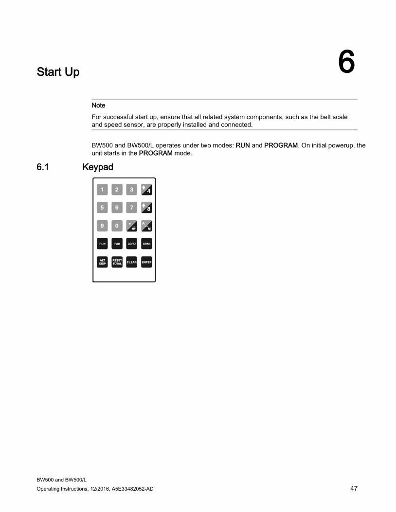
Note
For successful start up, ensure that all related system components, such as the belt scale and speed sensor, are properly installed and connected.
BW500 and BW500/L operates under two modes: RUN and PROGRAM. On initial powerup, the unit starts in the PROGRAM mode.
6.1 Keypad
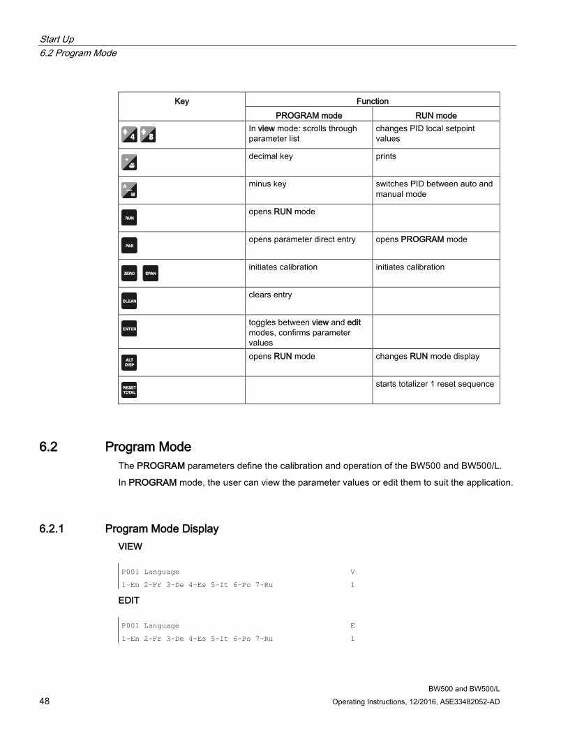
Start Up 6.2 Program Mode
BW500 and BW500/L 48 Operating Instructions, 12/2016, A5E33482052-AD
Key Function
PROGRAM mode RUN mode
In view mode: scrolls through parameter list
changes PID local setpoint values
decimal key prints
minus key switches PID between auto and
manual mode
opens RUN mode
opens parameter direct entry opens PROGRAM mode
initiates calibration initiates calibration
clears entry
toggles between view and edit modes, confirms parameter values
opens RUN mode changes RUN mode display
starts totalizer 1 reset sequence
6.2 Program Mode The PROGRAM parameters define the calibration and operation of the BW500 and BW500/L.
In PROGRAM mode, the user can view the parameter values or edit them to suit the application.
6.2.1 Program Mode Display VIEW P001 Language
1-En 2-Fr 3-De 4-Es 5-It 6-Po 7-Ru
V
1
EDIT P001 Language
1-En 2-Fr 3-De 4-Es 5-It 6-Po 7-Ru
E
1
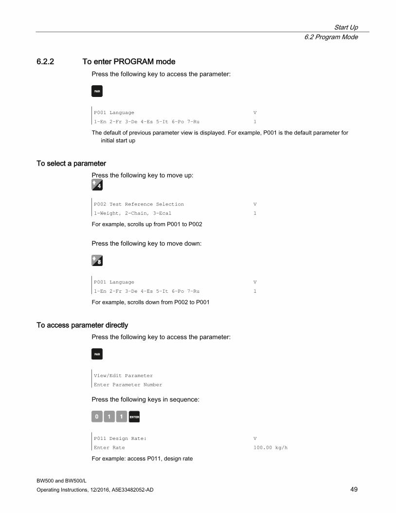
Start Up 6.2 Program Mode
BW500 and BW500/L Operating Instructions, 12/2016, A5E33482052-AD 49
6.2.2 To enter PROGRAM mode Press the following key to access the parameter:
P001 Language
1-En 2-Fr 3-De 4-Es 5-It 6-Po 7-Ru
V
1
The default of previous parameter view is displayed. For example, P001 is the default parameter for initial start up
To select a parameter Press the following key to move up:
P002 Test Reference Selection
1-Weight, 2-Chain, 3-Ecal
V
1
For example, scrolls up from P001 to P002
Press the following key to move down:
P001 Language
1-En 2-Fr 3-De 4-Es 5-It 6-Po 7-Ru
V
1
For example, scrolls down from P002 to P001
To access parameter directly Press the following key to access the parameter:
View/Edit Parameter
Enter Parameter Number
Press the following keys in sequence:
P011 Design Rate:
Enter Rate
V
100.00 kg/h
For example: access P011, design rate

Start Up 6.2 Program Mode
BW500 and BW500/L 50 Operating Instructions, 12/2016, A5E33482052-AD
Or press the following for the direct access of parameters:
P940-2 Load Cell mV Signal Test
mV reading for B
V
6.78
For example: access P940-2, load cell B mV signal
To change a parameter value P011 Design Rate:
Enter Rate
V
100.00 kg/h
From the view mode
Press the following key:
P011 Design Rate:
Enter Rate
E
100.00 kg/h
If edit mode is not enabled after pressing ENTER, security is locked. Refer toSecurityLock (P000) under Parameters for instructions on disabling.
Press the following key to enter the new value
P014 Design Speed
Enter Speed
V
0.08 m/s
For P001 to P017, ENTER effects the change and scrolls to the next required parameter.
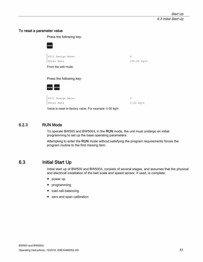
Start Up 6.3 Initial Start Up
BW500 and BW500/L Operating Instructions, 12/2016, A5E33482052-AD 51
To reset a parameter value Press the following key:
P011 Design Rate:
Enter Rate
E
100.00 kg/h
From the edit mode
Press the following key:
P011 Design Rate:
Enter Rate
V
0.00 kg/h
Value is reset to factory value. For example: 0.00 kg/h
6.2.3 RUN Mode To operate BW500 and BW500/L in the RUN mode, the unit must undergo an initial programming to set up the base operating parameters.
Attempting to enter the RUN mode without satisfying the program requirements forces the program routine to the first missing item.
6.3 Initial Start Up Initial start up of BW500 and BW500/L consists of several stages, and assumes that the physical and electrical installation of the belt scale and speed sensor, if used, is complete:
● power up
● programming
● load cell balancing
● zero and span calibration
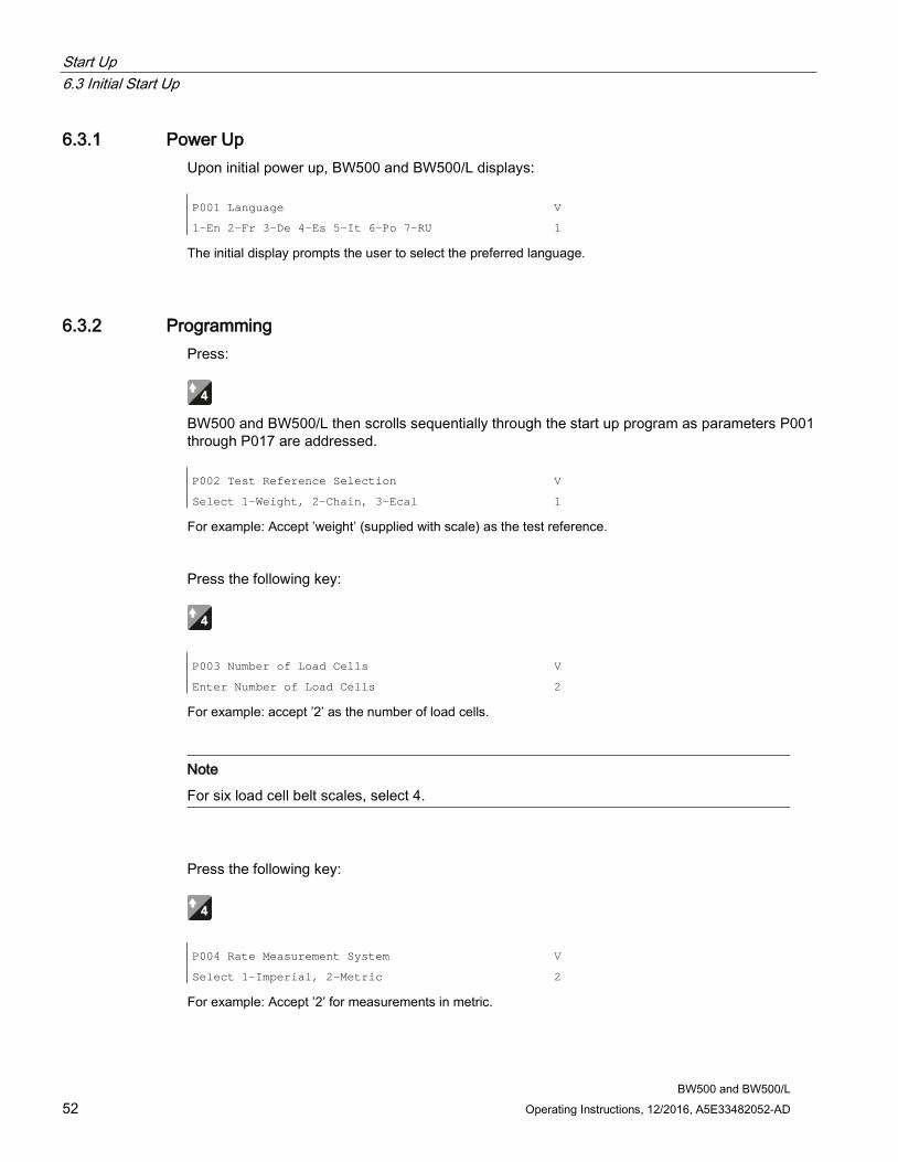
Start Up 6.3 Initial Start Up
BW500 and BW500/L 52 Operating Instructions, 12/2016, A5E33482052-AD
6.3.1 Power Up Upon initial power up, BW500 and BW500/L displays: P001 Language
1-En 2-Fr 3-De 4-Es 5-It 6-Po 7-RU
V
1
The initial display prompts the user to select the preferred language.
6.3.2 Programming Press:
BW500 and BW500/L then scrolls sequentially through the start up program as parameters P001 through P017 are addressed. P002 Test Reference Selection
Select 1-Weight, 2-Chain, 3-Ecal
V
1
For example: Accept ’weight’ (supplied with scale) as the test reference.
Press the following key:
P003 Number of Load Cells
Enter Number of Load Cells
V
2
For example: accept ’2’ as the number of load cells.
Note
For six load cell belt scales, select 4.
Press the following key:
P004 Rate Measurement System
Select 1-Imperial, 2-Metric
V
2
For example: Accept ’2’ for measurements in metric.
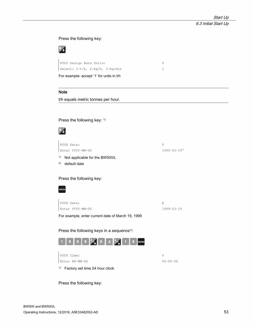
Start Up 6.3 Initial Start Up
BW500 and BW500/L Operating Instructions, 12/2016, A5E33482052-AD 53
Press the following key:
P005 Design Rate Units:
Select: 1-t/h, 2-kg/h, 3-kg/min
V
1
For example: accept ’1’ for units in t/h
Note
t/h equals metric tonnes per hour.
Press the following key: 1)
P008 Date:
Enter YYYY-MM-DD
V
1999-03-192)
1) Not applicable for the BW500/L 2) default date
Press the following key:
P008 Date:
Enter YYYY-MM-DD
E
1999-03-19
For example, enter current date of March 19, 1999
Press the following keys in a sequence1):
P009 Time:
Enter HH-MM-SS
V
00-00-00
1) Factory set time 24 hour clock
Press the following key:
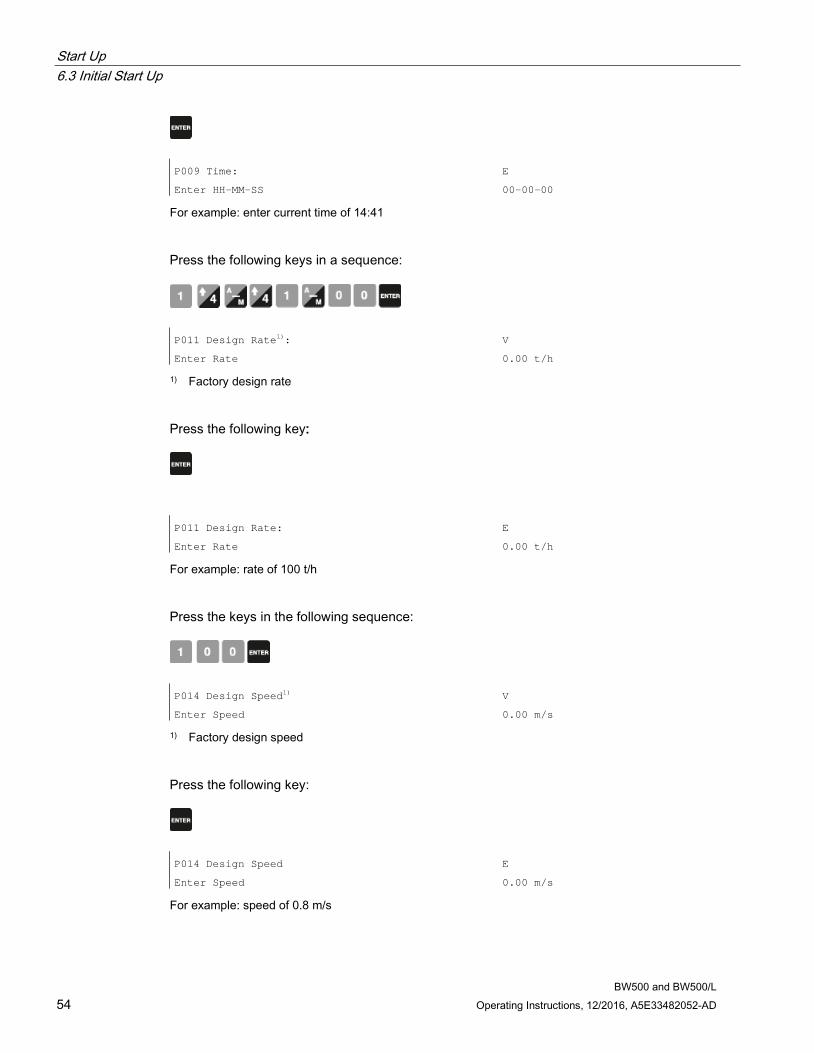
Start Up 6.3 Initial Start Up
BW500 and BW500/L 54 Operating Instructions, 12/2016, A5E33482052-AD
P009 Time:
Enter HH-MM-SS
E
00-00-00
For example: enter current time of 14:41
Press the following keys in a sequence:
P011 Design Rate1):
Enter Rate
V
0.00 t/h
1) Factory design rate
Press the following key:
P011 Design Rate:
Enter Rate
E
0.00 t/h
For example: rate of 100 t/h
Press the keys in the following sequence:
P014 Design Speed1)
Enter Speed
V
0.00 m/s
1) Factory design speed
Press the following key:
P014 Design Speed
Enter Speed
E
0.00 m/s
For example: speed of 0.8 m/s
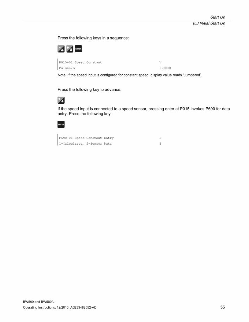
Start Up 6.3 Initial Start Up
BW500 and BW500/L Operating Instructions, 12/2016, A5E33482052-AD 55
Press the following keys in a sequence:
P015-01 Speed Constant
Pulses/m
V
0.0000
Note: If the speed input is configured for constant speed, display value reads ‘Jumpered’.
Press the following key to advance:
If the speed input is connected to a speed sensor, pressing enter at P015 invokes P690 for data entry. Press the following key:
P690-01 Speed Constant Entry
1-Calculated, 2-Sensor Data
E
1
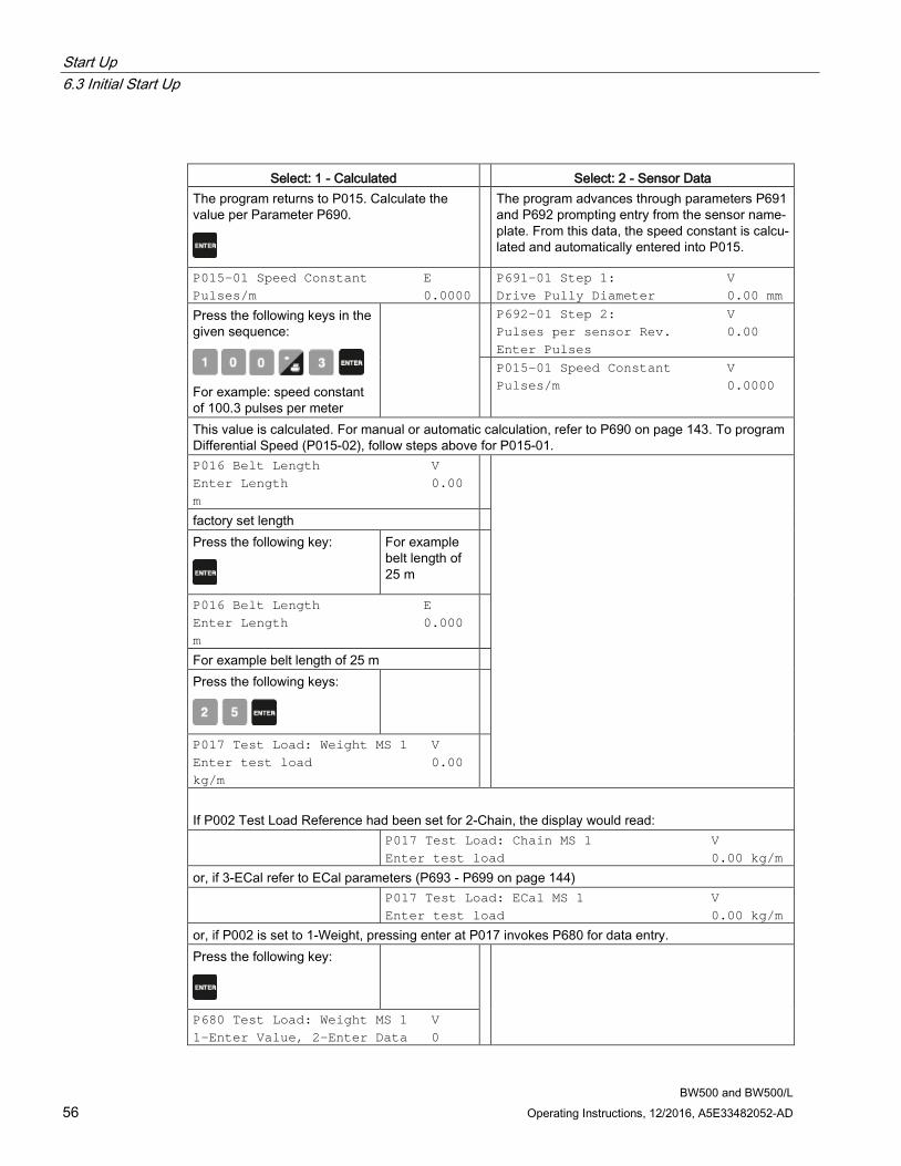
Start Up 6.3 Initial Start Up
BW500 and BW500/L 56 Operating Instructions, 12/2016, A5E33482052-AD
Select: 1 - Calculated Select: 2 - Sensor Data The program returns to P015. Calculate the value per Parameter P690.
The program advances through parameters P691 and P692 prompting entry from the sensor name-plate. From this data, the speed constant is calcu-lated and automatically entered into P015.
P015-01 Speed Constant E Pulses/m 0.0000
P691-01 Step 1: V Drive Pully Diameter 0.00 mm
Press the following keys in the given sequence:
For example: speed constant of 100.3 pulses per meter
P692-01 Step 2: V Pulses per sensor Rev. 0.00 Enter Pulses
P015-01 Speed Constant V Pulses/m 0.0000
This value is calculated. For manual or automatic calculation, refer to P690 on page 143. To program Differential Speed (P015-02), follow steps above for P015-01. P016 Belt Length V Enter Length 0.00 m
factory set length Press the following key:
For example belt length of 25 m
P016 Belt Length E Enter Length 0.000 m
For example belt length of 25 m Press the following keys:
P017 Test Load: Weight MS 1 V Enter test load 0.00 kg/m
If P002 Test Load Reference had been set for 2-Chain, the display would read: P017 Test Load: Chain MS 1 V
Enter test load 0.00 kg/m
or, if 3-ECal refer to ECal parameters (P693 - P699 on page 144) P017 Test Load: ECal MS 1 V
Enter test load 0.00 kg/m
or, if P002 is set to 1-Weight, pressing enter at P017 invokes P680 for data entry. Press the following key:
P680 Test Load: Weight MS 1 V 1-Enter Value, 2-Enter Data 0
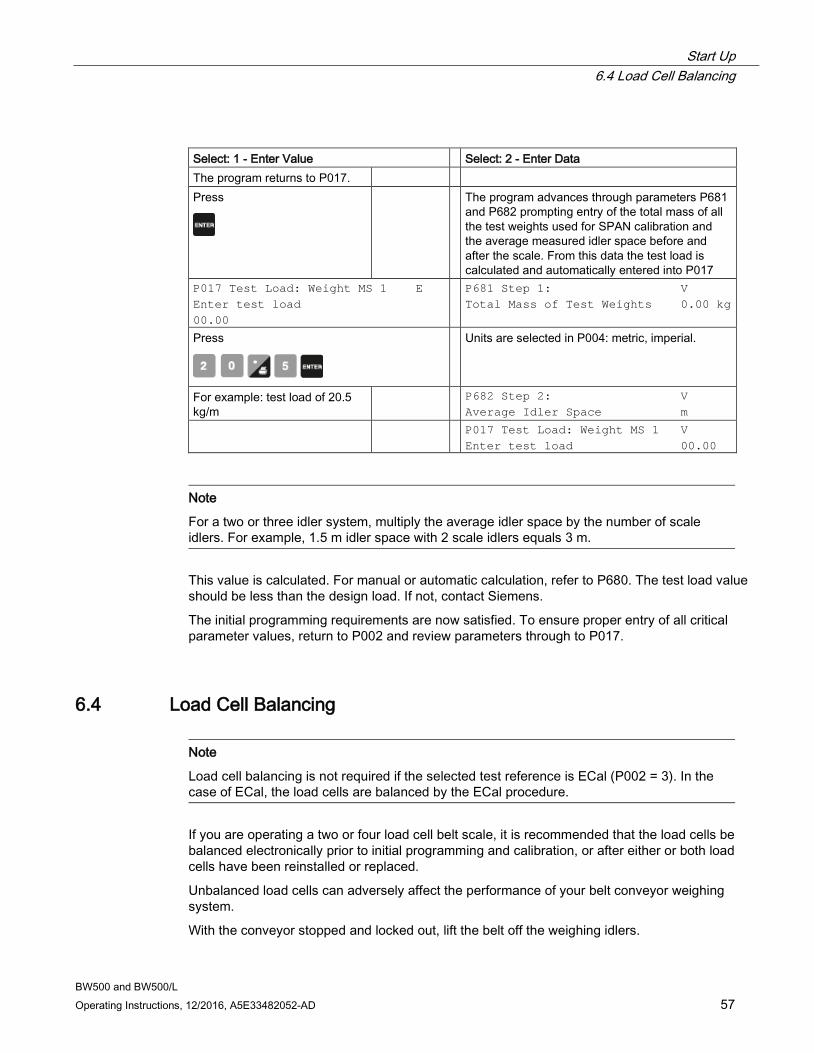
Start Up 6.4 Load Cell Balancing
BW500 and BW500/L Operating Instructions, 12/2016, A5E33482052-AD 57
Select: 1 - Enter Value Select: 2 - Enter Data The program returns to P017. Press
The program advances through parameters P681 and P682 prompting entry of the total mass of all the test weights used for SPAN calibration and the average measured idler space before and after the scale. From this data the test load is calculated and automatically entered into P017
P017 Test Load: Weight MS 1 E Enter test load 00.00
P681 Step 1: V Total Mass of Test Weights 0.00 kg
Press
Units are selected in P004: metric, imperial.
For example: test load of 20.5 kg/m
P682 Step 2: V Average Idler Space m
P017 Test Load: Weight MS 1 V Enter test load 00.00
Note
For a two or three idler system, multiply the average idler space by the number of scale idlers. For example, 1.5 m idler space with 2 scale idlers equals 3 m.
This value is calculated. For manual or automatic calculation, refer to P680. The test load value should be less than the design load. If not, contact Siemens.
The initial programming requirements are now satisfied. To ensure proper entry of all critical parameter values, return to P002 and review parameters through to P017.
6.4 Load Cell Balancing
Note
Load cell balancing is not required if the selected test reference is ECal (P002 = 3). In the case of ECal, the load cells are balanced by the ECal procedure.
If you are operating a two or four load cell belt scale, it is recommended that the load cells be balanced electronically prior to initial programming and calibration, or after either or both load cells have been reinstalled or replaced.
Unbalanced load cells can adversely affect the performance of your belt conveyor weighing system.
With the conveyor stopped and locked out, lift the belt off the weighing idlers.
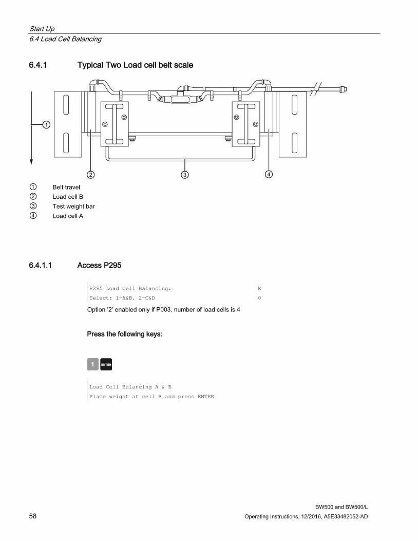
Start Up 6.4 Load Cell Balancing
BW500 and BW500/L 58 Operating Instructions, 12/2016, A5E33482052-AD
6.4.1 Typical Two Load cell belt scale
① Belt travel ② Load cell B ③ Test weight bar ④ Load cell A
6.4.1.1 Access P295 P295 Load Cell Balancing:
Select: 1-A&B, 2-C&D
E
0
Option ’2’ enabled only if P003, number of load cells is 4
Press the following keys:
Load Cell Balancing A & B
Place weight at cell B and press ENTER
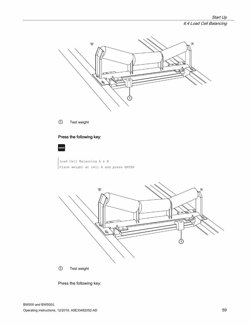
Start Up 6.4 Load Cell Balancing
BW500 and BW500/L Operating Instructions, 12/2016, A5E33482052-AD 59
① Test weight
Press the following key:
Load Cell Balancing A & B
Place weight at cell A and press ENTER
① Test weight
Press the following key:
Start Up 6.4 Load Cell Balancing
BW500 and BW500/L 60 Operating Instructions, 12/2016, A5E33482052-AD
Load Cell Balancing A & B
Load cells are now balanced
Balancing the load cells requires a subsequent zero and span calibration
If four load cell scale, press the following key to continue:
P295 Load Cell Balancing:
Select: 1-A&B, 2-C&D
V
1
Press the following key:
P295 Load Cell Balancing:
Select:1-A&B, 2-C&D
E
1
Press the following keys:
Load Cell Balancing C & D
Place weight at cell D and press ENTER
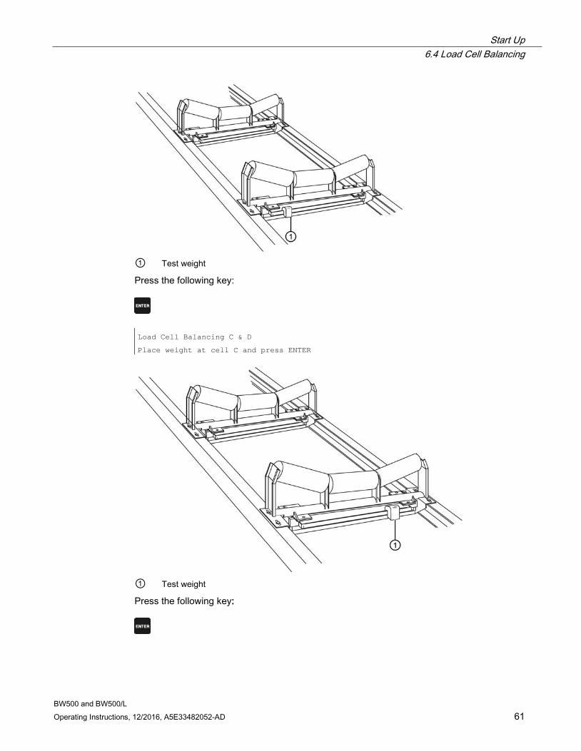
Start Up 6.4 Load Cell Balancing
BW500 and BW500/L Operating Instructions, 12/2016, A5E33482052-AD 61
① Test weight
Press the following key:
Load Cell Balancing C & D
Place weight at cell C and press ENTER
① Test weight
Press the following key:
Start Up 6.4 Load Cell Balancing
BW500 and BW500/L 62 Operating Instructions, 12/2016, A5E33482052-AD
Load Cell Balancing C &D
Load cells are now balanced
Balancing the load cells requires a subsequent zero and span recalibration
6.4.2 Balancing six load cell belt scales For a six load cell belt scale, the six load cells are connected into four inputs. Load cells A, C and E are connected into inputs A and C; load cells B, D and F are connected into inputs B and D.
Balancing load cells is still recommended to optimize system accuracy. The balancing needs to be done twice, once for P295–01 = A and B and then once for P295–02 = C and D.
Three weights that are all very close to the same mass are required.
6.4.2.1 Balancing for A and B 1. Place one weight at load cell B, one weight at load cell D and one weight at load cell F, all at
the same time.
2. Start the balancing procedure for A and B.
3. Press enter for B.
4. Move the 3 weights to A, C and E.
5. Press enter for A.
Balance for A side and B side is complete.
6.4.2.2 Balancing for C and D 1. Move all the weights back to B, D and F.
2. Set P295 to C and D.
3. Press enter for D (or B, depending on software revision).
4. Move the 3 weights again to A, C and E.
5. Press enter for C (or A, depending on software revision).
Balance for C and D is complete. Remove the weights and perform zero calibrations.
Note
After balancing is complete, applying a weight on A or B side should not result in the digital count values from PAR 943 being out by no more than a difference of 100.
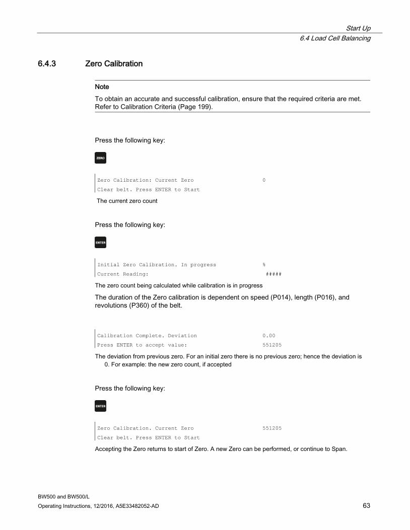
Start Up 6.4 Load Cell Balancing
BW500 and BW500/L Operating Instructions, 12/2016, A5E33482052-AD 63
6.4.3 Zero Calibration
Note
To obtain an accurate and successful calibration, ensure that the required criteria are met. Refer to Calibration Criteria (Page 199).
Press the following key:
Zero Calibration: Current Zero
Clear belt. Press ENTER to Start
0
The current zero count
Press the following key:
Initial Zero Calibration. In progress
Current Reading:
%
#####
The zero count being calculated while calibration is in progress
The duration of the Zero calibration is dependent on speed (P014), length (P016), and revolutions (P360) of the belt.
Calibration Complete. Deviation
Press ENTER to accept value:
0.00
551205
The deviation from previous zero. For an initial zero there is no previous zero; hence the deviation is 0. For example: the new zero count, if accepted
Press the following key:
Zero Calibration. Current Zero
Clear belt. Press ENTER to Start
551205
Accepting the Zero returns to start of Zero. A new Zero can be performed, or continue to Span.
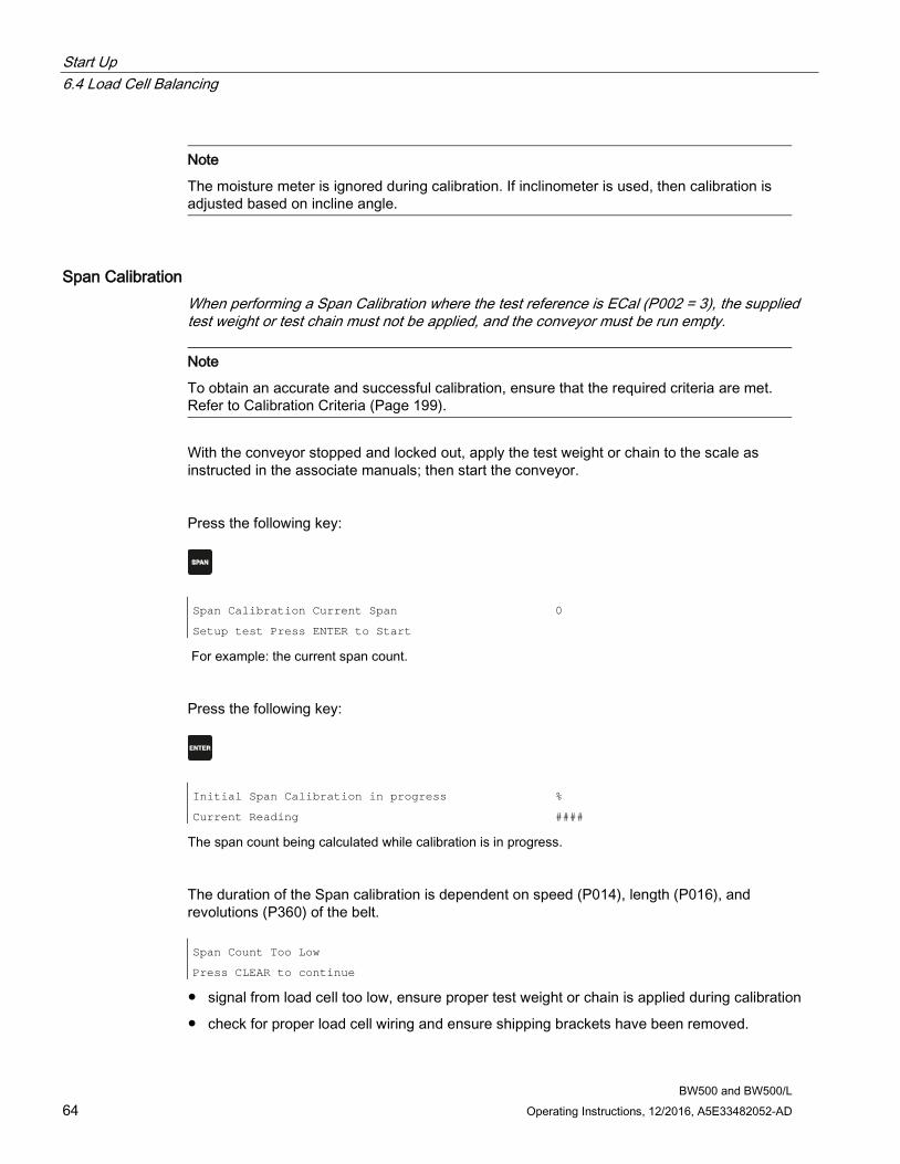
Start Up 6.4 Load Cell Balancing
BW500 and BW500/L 64 Operating Instructions, 12/2016, A5E33482052-AD
Note
The moisture meter is ignored during calibration. If inclinometer is used, then calibration is adjusted based on incline angle.
Span Calibration When performing a Span Calibration where the test reference is ECal (P002 = 3), the supplied test weight or test chain must not be applied, and the conveyor must be run empty.
Note
To obtain an accurate and successful calibration, ensure that the required criteria are met. Refer to Calibration Criteria (Page 199).
With the conveyor stopped and locked out, apply the test weight or chain to the scale as instructed in the associate manuals; then start the conveyor.
Press the following key:
Span Calibration Current Span
Setup test Press ENTER to Start
0
For example: the current span count.
Press the following key:
Initial Span Calibration in progress
Current Reading
%
####
The span count being calculated while calibration is in progress.
The duration of the Span calibration is dependent on speed (P014), length (P016), and revolutions (P360) of the belt. Span Count Too Low
Press CLEAR to continue
● signal from load cell too low, ensure proper test weight or chain is applied during calibration
● check for proper load cell wiring and ensure shipping brackets have been removed.

Start Up 6.4 Load Cell Balancing
BW500 and BW500/L Operating Instructions, 12/2016, A5E33482052-AD 65
Calibration Complete Deviation
Press ENTER to accept value:
0.00
36790
● the deviation from the previous span. For an initial span, there is no previous span count; hence the deviation is 0.
● For example: the new span count, if accepted.
Press the following key:
Span Calibration. Current Span
Setup test. Press ENTER to Start
36790
For example: the current span count.
Accepting the Span returns to start of Span. A new Span can be performed, or enter RUN mode. If calibrating with a test weight or test chain, remove it from the scale and store in a secure place before returning to RUN mode.
Note
The moisture meter is ignored during calibration. If the Inclinometer is used, then calibration is adjusted based on incline angle.
6.4.4 RUN Mode Proper programming and successful zero and span calibration allow entry into the RUN mode. Otherwise, entry is denied and the first missing item of programming or calibration is displayed.
Press the following key:
Rate
Total 1
0.00 t/h
0.00 t
For example: if there is no material on the belt and the conveyor is running. The current rate is 0 and no material has been totalized.
Once the initial programming is complete and the BW500 and BW500/L is operating in the RUN mode, you may now put the belt conveyor into normal service. The BW500 is functioning under its initial program and calibration, reporting rate of material flow and totalizing.

Start Up 6.4 Load Cell Balancing
BW500 and BW500/L 66 Operating Instructions, 12/2016, A5E33482052-AD
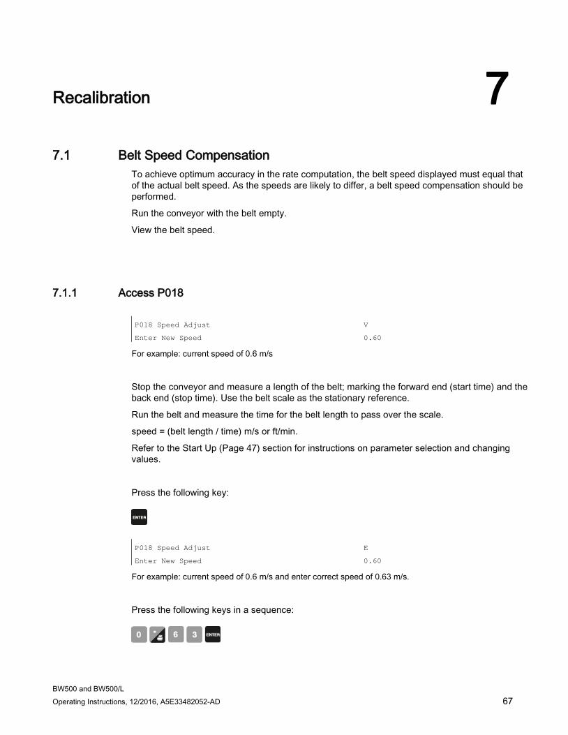
BW500 and BW500/L Operating Instructions, 12/2016, A5E33482052-AD 67
Recalibration 7 7.1 Belt Speed Compensation
To achieve optimum accuracy in the rate computation, the belt speed displayed must equal that of the actual belt speed. As the speeds are likely to differ, a belt speed compensation should be performed.
Run the conveyor with the belt empty.
View the belt speed.
7.1.1 Access P018 P018 Speed Adjust
Enter New Speed
V
0.60
For example: current speed of 0.6 m/s
Stop the conveyor and measure a length of the belt; marking the forward end (start time) and the back end (stop time). Use the belt scale as the stationary reference.
Run the belt and measure the time for the belt length to pass over the scale.
speed = (belt length / time) m/s or ft/min.
Refer to the Start Up (Page 47) section for instructions on parameter selection and changing values.
Press the following key:
P018 Speed Adjust
Enter New Speed
E
0.60
For example: current speed of 0.6 m/s and enter correct speed of 0.63 m/s.
Press the following keys in a sequence:
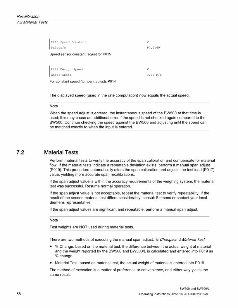
Recalibration 7.2 Material Tests
BW500 and BW500/L 68 Operating Instructions, 12/2016, A5E33482052-AD
P015 Speed Constant V
Pulses/m 97.5169
Speed sensor constant, adjust for P015
P014 Design Speed
Enter Speed
V
0.63 m/s
For constant speed (jumper), adjusts P014
The displayed speed (used in the rate computation) now equals the actual speed.
Note
When the speed adjust is entered, the instantaneous speed of the BW500 at that time is used; this may cause an additional error if the speed is not checked again compared to the BW500. Continue checking the speed against the BW500 and adjusting until the speed can be matched exactly to when the input is entered.
7.2 Material Tests Perform material tests to verify the accuracy of the span calibration and compensate for material flow. If the material tests indicate a repeatable deviation exists, perform a manual span adjust (P019). This procedure automatically alters the span calibration and adjusts the test load (P017) value, yielding more accurate span recalibrations.
If the span adjust value is within the accuracy requirements of the weighing system, the material test was successful. Resume normal operation.
If the span adjust value is not acceptable, repeat the material test to verify repeatability. If the result of the second material test differs considerably, consult Siemens or contact your local Siemens representative.
If the span adjust values are significant and repeatable, perform a manual span adjust.
Note
Test weights are NOT used during material tests.
There are two methods of executing the manual span adjust: % Change and Material Test ● % Change: based on the material test, the difference between the actual weight of material
and the weight reported by the BW500 and BW500/L is calculated and entered into P019 as % change.
● Material Test: based on material test, the actual weight of material is entered into P019
The method of execution is a matter of preference or convenience, and either way yields the same result.

Recalibration 7.2 Material Tests
BW500 and BW500/L Operating Instructions, 12/2016, A5E33482052-AD 69
7.2.1 %Change To run a %Change material test:
1. Run the belt empty
2. Perform a zero calibration
3. Put the BW500 and BW500/L into RUN mode
4. Record the BW500 and BW500/L total as the start value _ _ _ _ _ _ _
5. Run material at a minimum of 50% of design rate over the belt scale for a minimum of 5 minutes
6. Stop the material feed and run the conveyor empty
7. Record the BW500 and BW500/L total as the stop value _ _ _ _ _ _ _
8. Subtract the start value from the stop value to determine the BW500 and BW500/L total
9. Weigh the material sample if not already known
BW500 and BW500/L total = _ _ _ _ _ _ _
material sample weight = _ _ _ _ _ _ _
Calculate the span adjust value
% span adjust = (BW500 - material sample weight) x 100/ material sample weight
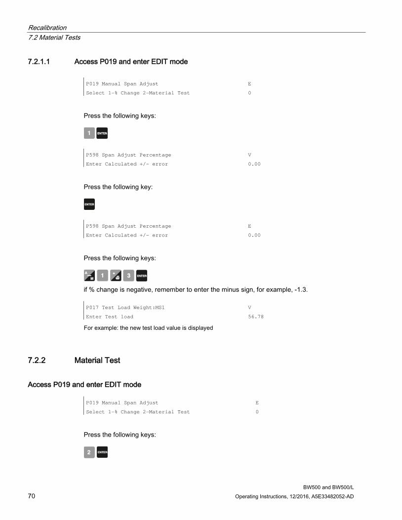
Recalibration 7.2 Material Tests
BW500 and BW500/L 70 Operating Instructions, 12/2016, A5E33482052-AD
7.2.1.1 Access P019 and enter EDIT mode P019 Manual Span Adjust
Select 1-% Change 2-Material Test
E
0
Press the following keys:
P598 Span Adjust Percentage
Enter Calculated +/- error
V
0.00
Press the following key:
P598 Span Adjust Percentage
Enter Calculated +/- error
E
0.00
Press the following keys:
if % change is negative, remember to enter the minus sign, for example, -1.3. P017 Test Load Weight:MS1
Enter Test load
V
56.78
For example: the new test load value is displayed
7.2.2 Material Test
Access P019 and enter EDIT mode P019 Manual Span Adjust
Select 1-% Change 2-Material Test
E
0
Press the following keys:
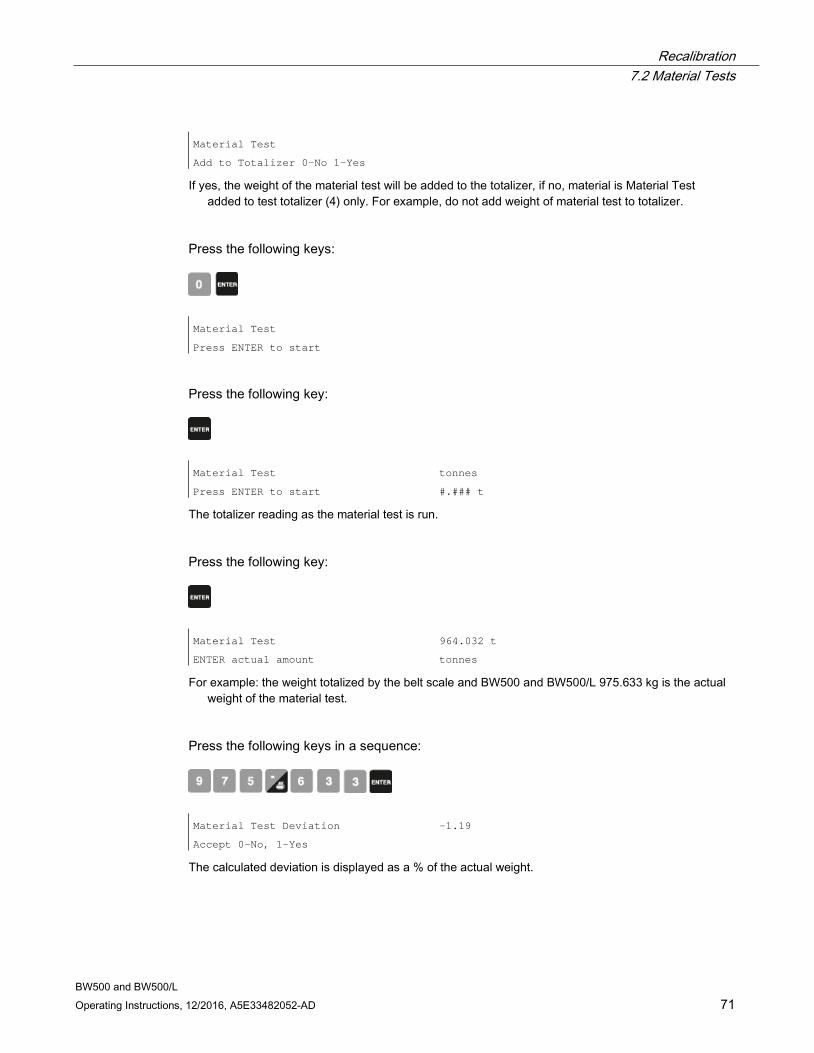
Recalibration 7.2 Material Tests
BW500 and BW500/L Operating Instructions, 12/2016, A5E33482052-AD 71
Material Test
Add to Totalizer 0-No 1-Yes
If yes, the weight of the material test will be added to the totalizer, if no, material is Material Test added to test totalizer (4) only. For example, do not add weight of material test to totalizer.
Press the following keys:
Material Test
Press ENTER to start
Press the following key:
Material Test
Press ENTER to start
tonnes
#.### t
The totalizer reading as the material test is run.
Press the following key:
Material Test
ENTER actual amount
964.032 t
tonnes
For example: the weight totalized by the belt scale and BW500 and BW500/L 975.633 kg is the actual weight of the material test.
Press the following keys in a sequence:
Material Test Deviation
Accept 0-No, 1-Yes
-1.19
The calculated deviation is displayed as a % of the actual weight.
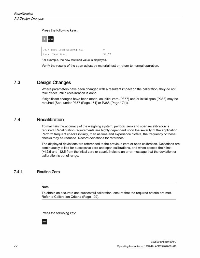
Recalibration 7.3 Design Changes
BW500 and BW500/L 72 Operating Instructions, 12/2016, A5E33482052-AD
Press the following keys:
P017 Test Load Weight: MS1
Enter Test Load
V
56.78
For example, the new test load value is displayed.
Verify the results of the span adjust by material test or return to normal operation.
7.3 Design Changes Where parameters have been changed with a resultant impact on the calibration, they do not take effect until a recalibration is done.
If significant changes have been made, an initial zero (P377) and/or initial span (P388) may be required (See, under P377 (Page 171) or P388 (Page 171)).
7.4 Recalibration To maintain the accuracy of the weighing system, periodic zero and span recalibration is required. Recalibration requirements are highly dependent upon the severity of the application. Perform frequent checks initially, then as time and experience dictate, the frequency of these checks may be reduced. Record deviations for reference.
The displayed deviations are referenced to the previous zero or span calibration. Deviations are continuously tallied for successive zero and span calibrations, and when exceed their limit (+12.5 and -12.5 from the initial zero or span), indicate an error message that the deviation or calibration is out of range.
7.4.1 Routine Zero
Note
To obtain an accurate and successful calibration, ensure that the required criteria are met. Refer to Calibration Criteria (Page 199).
Press the follwoing key:

Recalibration 7.4 Recalibration
BW500 and BW500/L Operating Instructions, 12/2016, A5E33482052-AD 73
Zero Calibration. Current Zero.
Clear belt. Press ENTER to start
551205
For example: the current zero count.
Press the following key:
Zero Calibration in progress
Current Reading:
%
0.01 kg/m
For example: the load reported while calibration is in progress
Calibration complete. Deviation
Press ENTER to accept value
0.02
551418
For example: the calculated deviation in % of full span and the new zero count, if accepted.
A deviation that is high (Siemens recommends 3 or higher) should be investigated further to identify the source). Calibration is out of range
Deviation report:
403.37
If unacceptable, press the following key to restart:
This indicates that the mechanical system is errant. P377, initial zero, should be used judiciously and only after a thorough mechanical investigation.
The cause of the increased deviation must be found and rectified. A zero recalibration as previously described can then be retried.
If the operator deems this deviation to be acceptable, set P377 to 1 to invoke an initial zero calibration. Further deviation limits are now based on this new initial zero.
Press the following key:
Zero Calibration. Current Zero
Clear belt. Press ENTER to start
551418
For example: zero calibration is accepted, played as the current zero.
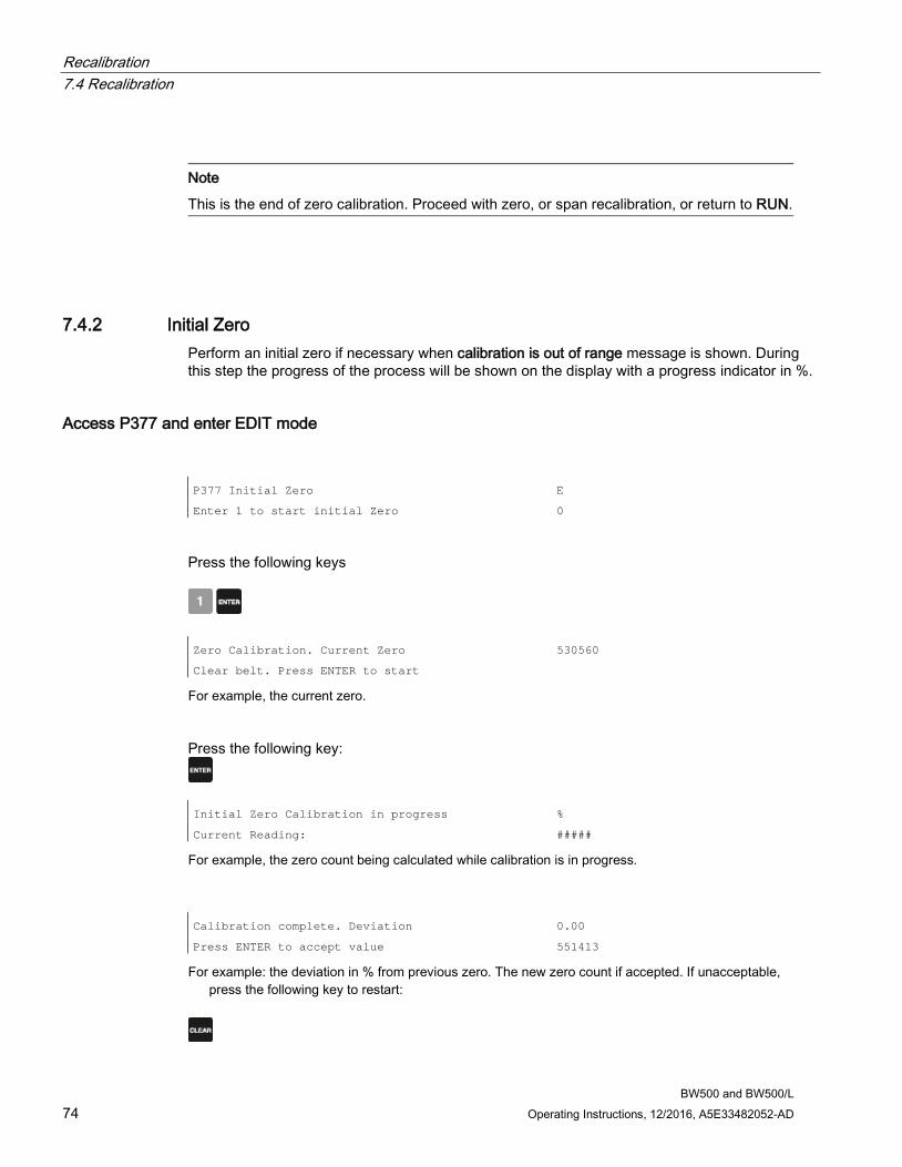
Recalibration 7.4 Recalibration
BW500 and BW500/L 74 Operating Instructions, 12/2016, A5E33482052-AD
Note
This is the end of zero calibration. Proceed with zero, or span recalibration, or return to RUN.
7.4.2 Initial Zero Perform an initial zero if necessary when calibration is out of range message is shown. During this step the progress of the process will be shown on the display with a progress indicator in %.
Access P377 and enter EDIT mode P377 Initial Zero
Enter 1 to start initial Zero
E
0
Press the following keys
Zero Calibration. Current Zero
Clear belt. Press ENTER to start
530560
For example, the current zero.
Press the following key:
Initial Zero Calibration in progress %
Current Reading: #####
For example, the zero count being calculated while calibration is in progress.
Calibration complete. Deviation
Press ENTER to accept value
0.00
551413
For example: the deviation in % from previous zero. The new zero count if accepted. If unacceptable, press the following key to restart:
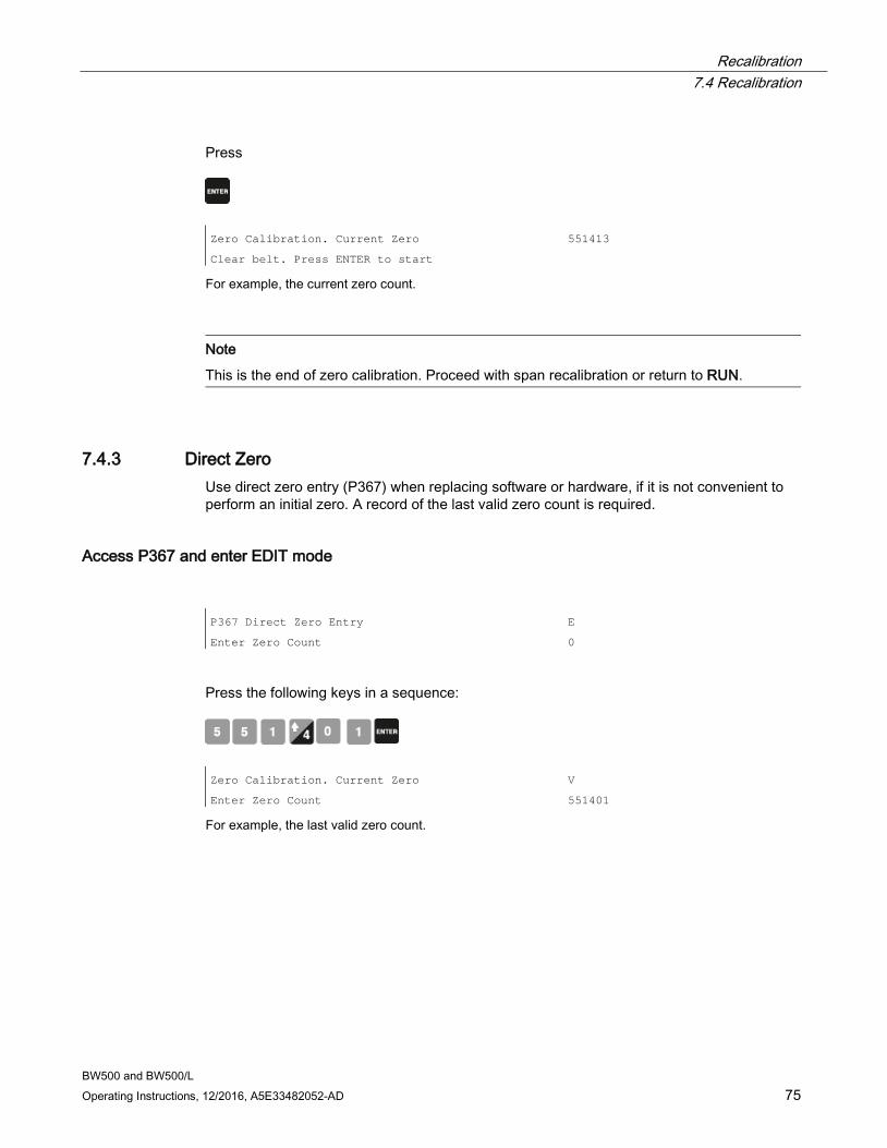
Recalibration 7.4 Recalibration
BW500 and BW500/L Operating Instructions, 12/2016, A5E33482052-AD 75
Press
Zero Calibration. Current Zero
Clear belt. Press ENTER to start
551413
For example, the current zero count.
Note
This is the end of zero calibration. Proceed with span recalibration or return to RUN.
7.4.3 Direct Zero Use direct zero entry (P367) when replacing software or hardware, if it is not convenient to perform an initial zero. A record of the last valid zero count is required.
Access P367 and enter EDIT mode P367 Direct Zero Entry
Enter Zero Count
E
0
Press the following keys in a sequence:
Zero Calibration. Current Zero
Enter Zero Count
V
551401
For example, the last valid zero count.
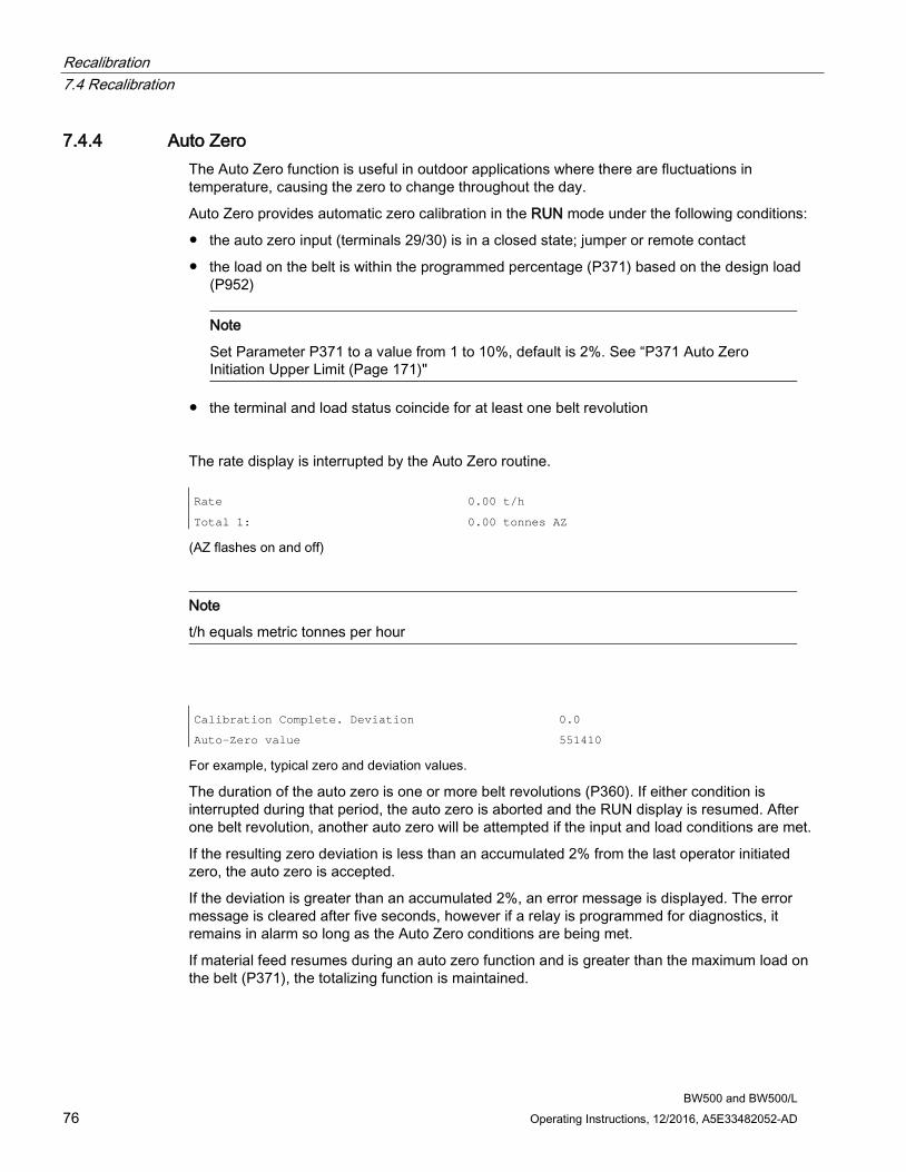
Recalibration 7.4 Recalibration
BW500 and BW500/L 76 Operating Instructions, 12/2016, A5E33482052-AD
7.4.4 Auto Zero The Auto Zero function is useful in outdoor applications where there are fluctuations in temperature, causing the zero to change throughout the day.
Auto Zero provides automatic zero calibration in the RUN mode under the following conditions:
● the auto zero input (terminals 29/30) is in a closed state; jumper or remote contact
● the load on the belt is within the programmed percentage (P371) based on the design load (P952)
Note
Set Parameter P371 to a value from 1 to 10%, default is 2%. See “P371 Auto Zero Initiation Upper Limit (Page 171)"
● the terminal and load status coincide for at least one belt revolution
The rate display is interrupted by the Auto Zero routine. Rate
Total 1:
0.00 t/h
0.00 tonnes AZ
(AZ flashes on and off)
Note
t/h equals metric tonnes per hour
Calibration Complete. Deviation
Auto-Zero value
0.0
551410
For example, typical zero and deviation values.
The duration of the auto zero is one or more belt revolutions (P360). If either condition is interrupted during that period, the auto zero is aborted and the RUN display is resumed. After one belt revolution, another auto zero will be attempted if the input and load conditions are met.
If the resulting zero deviation is less than an accumulated 2% from the last operator initiated zero, the auto zero is accepted.
If the deviation is greater than an accumulated 2%, an error message is displayed. The error message is cleared after five seconds, however if a relay is programmed for diagnostics, it remains in alarm so long as the Auto Zero conditions are being met.
If material feed resumes during an auto zero function and is greater than the maximum load on the belt (P371), the totalizing function is maintained.
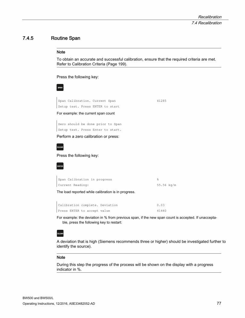
Recalibration 7.4 Recalibration
BW500 and BW500/L Operating Instructions, 12/2016, A5E33482052-AD 77
7.4.5 Routine Span
Note
To obtain an accurate and successful calibration, ensure that the required criteria are met. Refer to Calibration Criteria (Page 199).
Press the following key:
Span Calibration. Current Span
Setup test. Press ENTER to start
41285
For example: the current span count Zero should be done prior to Span
Setup test. Press Enter to start.
Perform a zero calibration or press:
Press the following key:
Span Calibration in progress
Current Reading:
%
55.56 kg/m
The load reported while calibration is in progress.
Calibration complete. Deviation
Press ENTER to accept value
0.03
41440
For example: the deviation in % from previous span, if the new span count is accepted. If unaccepta-ble, press the following key to restart:
A deviation that is high (Siemens recommends three or higher) should be investigated further to identify the source).
Note
During this step the progress of the process will be shown on the display with a progress indicator in %.
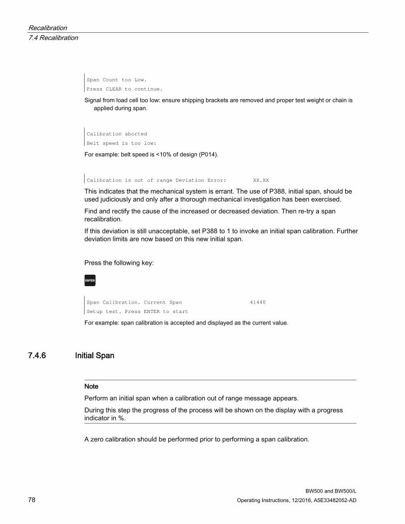
Recalibration 7.4 Recalibration
BW500 and BW500/L 78 Operating Instructions, 12/2016, A5E33482052-AD
Span Count too Low.
Press CLEAR to continue.
Signal from load cell too low: ensure shipping brackets are removed and proper test weight or chain is applied during span.
Calibration aborted
Belt speed is too low:
For example: belt speed is <10% of design (P014).
Calibration is out of range Deviation Error: XX.XX
This indicates that the mechanical system is errant. The use of P388, initial span, should be used judiciously and only after a thorough mechanical investigation has been exercised.
Find and rectify the cause of the increased or decreased deviation. Then re-try a span recalibration.
If this deviation is still unacceptable, set P388 to 1 to invoke an initial span calibration. Further deviation limits are now based on this new initial span.
Press the following key:
Span Calibration. Current Span
Setup test. Press ENTER to start
41440
For example: span calibration is accepted and displayed as the current value.
7.4.6 Initial Span
Note
Perform an initial span when a calibration out of range message appears.
During this step the progress of the process will be shown on the display with a progress indicator in %.
A zero calibration should be performed prior to performing a span calibration.
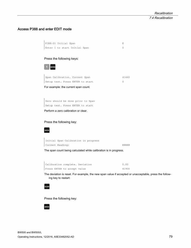
Recalibration 7.4 Recalibration
BW500 and BW500/L Operating Instructions, 12/2016, A5E33482052-AD 79
Access P388 and enter EDIT mode P388-01 Initial Span
Enter 1 to start Initial Span
E
0
Press the following keys:
Span Calibration. Current Span
Setup test. Press ENTER to start
41440
0
For example: the current span count.
Zero should be done prior to Span
Setup test. Press ENTER to start
Perform a zero calibration or clear.
Press the following key:
Initial Span Calibration in progress
Current Reading:
#####
The span count being calculated while calibration is in progress.
Calibration complete. Deviation
Press ENTER to accept value
0.00
41900
The deviation is reset. For example, the new span value if accepted or unacceptable, press the follow-ing key to restart:
Press the following key:
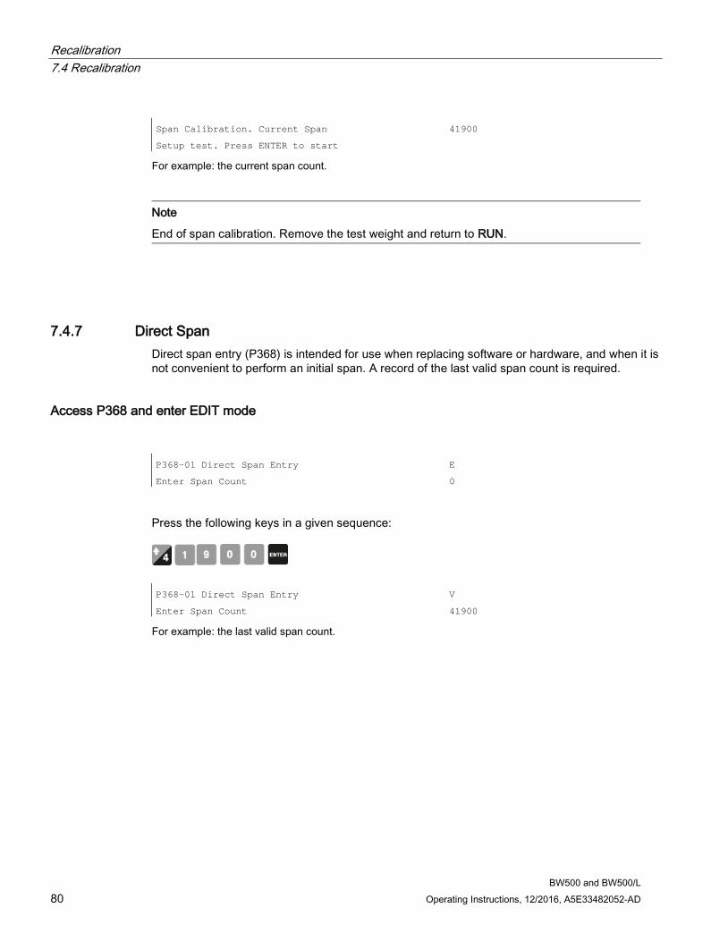
Recalibration 7.4 Recalibration
BW500 and BW500/L 80 Operating Instructions, 12/2016, A5E33482052-AD
Span Calibration. Current Span
Setup test. Press ENTER to start
41900
For example: the current span count.
Note
End of span calibration. Remove the test weight and return to RUN.
7.4.7 Direct Span Direct span entry (P368) is intended for use when replacing software or hardware, and when it is not convenient to perform an initial span. A record of the last valid span count is required.
Access P368 and enter EDIT mode P368-01 Direct Span Entry
Enter Span Count
E
0
Press the following keys in a given sequence:
P368-01 Direct Span Entry
Enter Span Count
V
41900
For example: the last valid span count.
Recalibration 7.4 Recalibration
BW500 and BW500/L Operating Instructions, 12/2016, A5E33482052-AD 81
7.4.8 Multispan The BW500 offers a multispan function, which allows the BW500 to be calibrated for up to eight different feed conditions that would produce varying load characteristics. Different feed conditions are typically related to the running of different materials or multiple feed locations. The varying load characteristic often has a bearing on the belt tension, and is observed especially when in close proximity to the scale. To accommodate such scale applications, a span correction can be made by selecting and applying the appropriate span.
Since every material has its own unique physical properties, and may load the belt differently, a span calibration may be required for each material to realize maximum accuracy.
In the case of different feeder locations, a span calibration may be required to match each feedpoint or combination of feedpoints.
Each time one of the eight conditions is in effect, the corresponding multispan is selected prior to putting the BW500 into the RUN mode. The selection is made by either changing the multispan operation number, accessed via P365, or by external contacts connected to the Auxiliary input, and programmed via P270.
To enable multispan operation, the following must be addressed.
● connections
● programming
● calibration
● operation
Note
Multispan is not available with BW500/L.
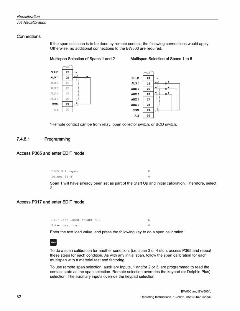
Recalibration 7.4 Recalibration
BW500 and BW500/L 82 Operating Instructions, 12/2016, A5E33482052-AD
Connections If the span selection is to be done by remote contact, the following connections would apply. Otherwise, no additional connections to the BW500 are required. Multispan Selection of Spans 1 and 2 Multispan Selection of Spans 1 to 8
*Remote contact can be from relay, open collector switch, or BCD switch.
7.4.8.1 Programming
Access P365 and enter EDIT mode P365 Multispan
Select [1-8]
E
0
Span 1 will have already been set as part of the Start Up and initial calibration. Therefore, select 2.
Access P017 and enter EDIT mode P017 Test Load: Weight MS2
Enter test load
E
0
Enter the test load value, and press the following key to do a span calibration:
To do a span calibration for another condition, (i.e. span 3 or 4 etc.), access P365 and repeat these steps for each condition. As with any initial span, follow the span calibration for each multispan with a material test and factoring.
To use remote span selection, auxilliary Inputs, 1 and/or 2 or 3, are programmed to read the contact state as the span selection. Remote selection overrides the keypad (or Dolphin Plus) selection. The auxilliary inputs override the keypad selection.
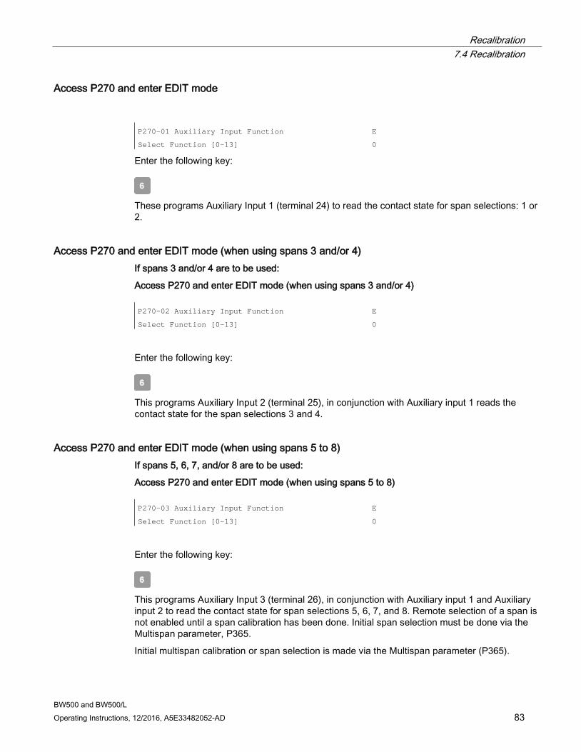
Recalibration 7.4 Recalibration
BW500 and BW500/L Operating Instructions, 12/2016, A5E33482052-AD 83
Access P270 and enter EDIT mode P270-01 Auxiliary Input Function
Select Function [0-13]
E
0
Enter the following key:
These programs Auxiliary Input 1 (terminal 24) to read the contact state for span selections: 1 or 2.
Access P270 and enter EDIT mode (when using spans 3 and/or 4) If spans 3 and/or 4 are to be used:
Access P270 and enter EDIT mode (when using spans 3 and/or 4) P270-02 Auxiliary Input Function
Select Function [0-13]
E
0
Enter the following key:
This programs Auxiliary Input 2 (terminal 25), in conjunction with Auxiliary input 1 reads the contact state for the span selections 3 and 4.
Access P270 and enter EDIT mode (when using spans 5 to 8) If spans 5, 6, 7, and/or 8 are to be used:
Access P270 and enter EDIT mode (when using spans 5 to 8) P270-03 Auxiliary Input Function
Select Function [0-13]
E
0
Enter the following key:
This programs Auxiliary Input 3 (terminal 26), in conjunction with Auxiliary input 1 and Auxiliary input 2 to read the contact state for span selections 5, 6, 7, and 8. Remote selection of a span is not enabled until a span calibration has been done. Initial span selection must be done via the Multispan parameter, P365.
Initial multispan calibration or span selection is made via the Multispan parameter (P365).
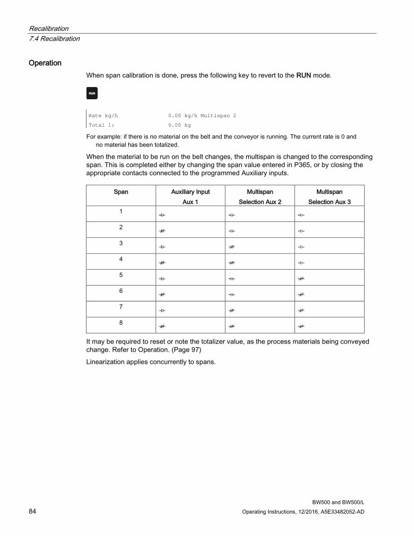
Recalibration 7.4 Recalibration
BW500 and BW500/L 84 Operating Instructions, 12/2016, A5E33482052-AD
Operation When span calibration is done, press the following key to revert to the RUN mode.
Rate kg/h
Total 1:
0.00 kg/h Multispan 2
0.00 kg
For example: if there is no material on the belt and the conveyor is running. The current rate is 0 and no material has been totalized.
When the material to be run on the belt changes, the multispan is changed to the corresponding span. This is completed either by changing the span value entered in P365, or by closing the appropriate contacts connected to the programmed Auxiliary inputs.
Span Auxiliary Input Aux 1
Multispan Selection Aux 2
Multispan Selection Aux 3
1
2
3
4
5
6
7
8
It may be required to reset or note the totalizer value, as the process materials being conveyed change. Refer to Operation. (Page 97)
Linearization applies concurrently to spans.
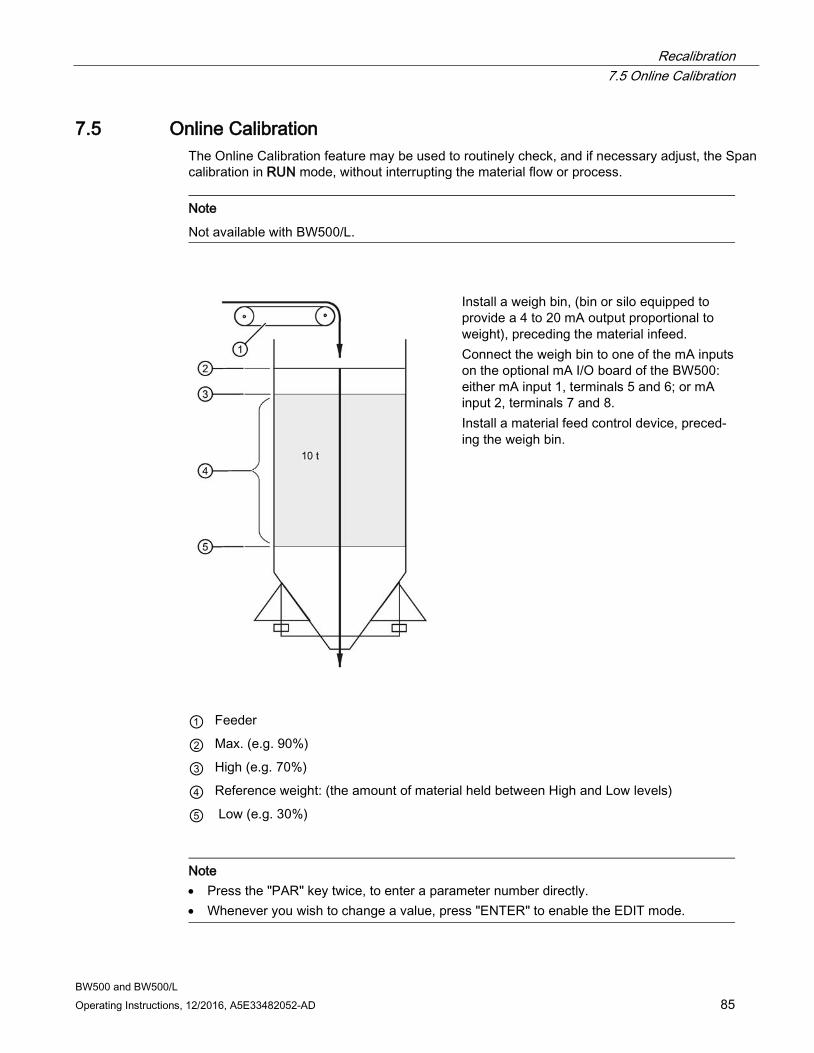
Recalibration 7.5 Online Calibration
BW500 and BW500/L Operating Instructions, 12/2016, A5E33482052-AD 85
7.5 Online Calibration The Online Calibration feature may be used to routinely check, and if necessary adjust, the Span calibration in RUN mode, without interrupting the material flow or process.
Note
Not available with BW500/L.
Install a weigh bin, (bin or silo equipped to provide a 4 to 20 mA output proportional to weight), preceding the material infeed. Connect the weigh bin to one of the mA inputs on the optional mA I/O board of the BW500: either mA input 1, terminals 5 and 6; or mA input 2, terminals 7 and 8. Install a material feed control device, preced-ing the weigh bin.
① Feeder
② Max. (e.g. 90%)
③ High (e.g. 70%)
④ Reference weight: (the amount of material held between High and Low levels)
⑤ Low (e.g. 30%)
Note • Press the "PAR" key twice, to enter a parameter number directly. • Whenever you wish to change a value, press "ENTER" to enable the EDIT mode.
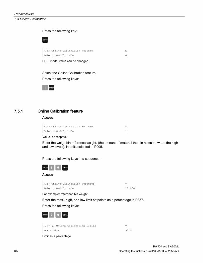
Recalibration 7.5 Online Calibration
BW500 and BW500/L 86 Operating Instructions, 12/2016, A5E33482052-AD
Press the following key:
P355 Online Calibration Feature
Select: 0-Off, 1-On
E
0
EDIT mode: value can be changed.
Select the Online Calibration feature:
Press the following keys:
7.5.1 Online Calibration feature Access P355 Online Calibration Features
Select: 0-Off, 1-On
V
1
Value is accepted.
Enter the weigh bin reference weight, (the amount of material the bin holds between the high and low levels), in units selected in P005.
Press the following keys in a sequence:
Access P356 Online Calibration Features
Select: 0-Off, 1-On
V
10.000
For example: reference bin weight.
Enter the max., high, and low limit setpoints as a percentage in P357.
Press the following keys:
P357-01 Online Calibration Limits
MAX Limit:
V
90.0
Limit as a percentage
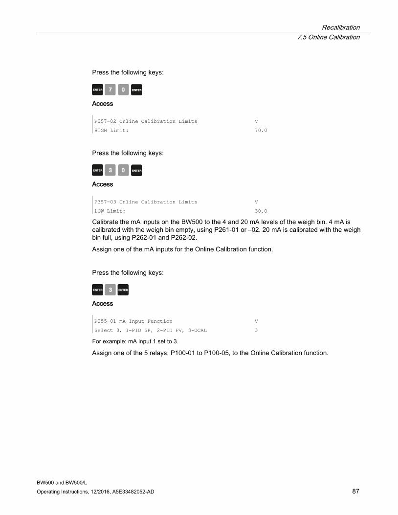
Recalibration 7.5 Online Calibration
BW500 and BW500/L Operating Instructions, 12/2016, A5E33482052-AD 87
Press the following keys:
Access P357-02 Online Calibration Limits
HIGH Limit:
V
70.0
Press the following keys:
Access P357-03 Online Calibration Limits
LOW Limit:
V
30.0
Calibrate the mA inputs on the BW500 to the 4 and 20 mA levels of the weigh bin. 4 mA is calibrated with the weigh bin empty, using P261-01 or –02. 20 mA is calibrated with the weigh bin full, using P262-01 and P262-02.
Assign one of the mA inputs for the Online Calibration function.
Press the following keys:
Access P255-01 mA Input Function
Select 0, 1-PID SP, 2-PID FV, 3-OCAL
V
3
For example: mA input 1 set to 3.
Assign one of the 5 relays, P100-01 to P100-05, to the Online Calibration function.

Recalibration 7.5 Online Calibration
BW500 and BW500/L 88 Operating Instructions, 12/2016, A5E33482052-AD
Press the following keys:
Access P100-01 Relay Function
Select Function [0-9] (see manual)
V
9
For example: relay 1 set to 9.
Program the assigned relay using P118, relay logic, so that when you connect the assigned relay to the weigh bin material feed control device, the weigh bin material feed stops when the Online relay is energized.
7.5.2 Activate Online Calibration Activate Online Calibration
Press the following keys:
P358 Online Calibration Features
0-OFF, 1-ACTIVE
V
Note
For remote access, Online Calibration can also be activated using one of the Auxiliary inputs (refer to P270 (Page 165))
When the Online Calibration is activated, normal operation continues until the weigh bin fills to the maximum level, (90% in the example shown). During the filling stage, the current level is displayed as a percentage.
Online Calibration -
Wait for LEVEL > MAX
LOW > 19%
RLY
Current level displayed as percentage.
When the maximum limit is reached, the relay assigned to the Online Calibration function energizes to stop the weigh bin material feed. Online Calibration -
Wait for LEVEL < HIGH
94% > MAX
RLY1
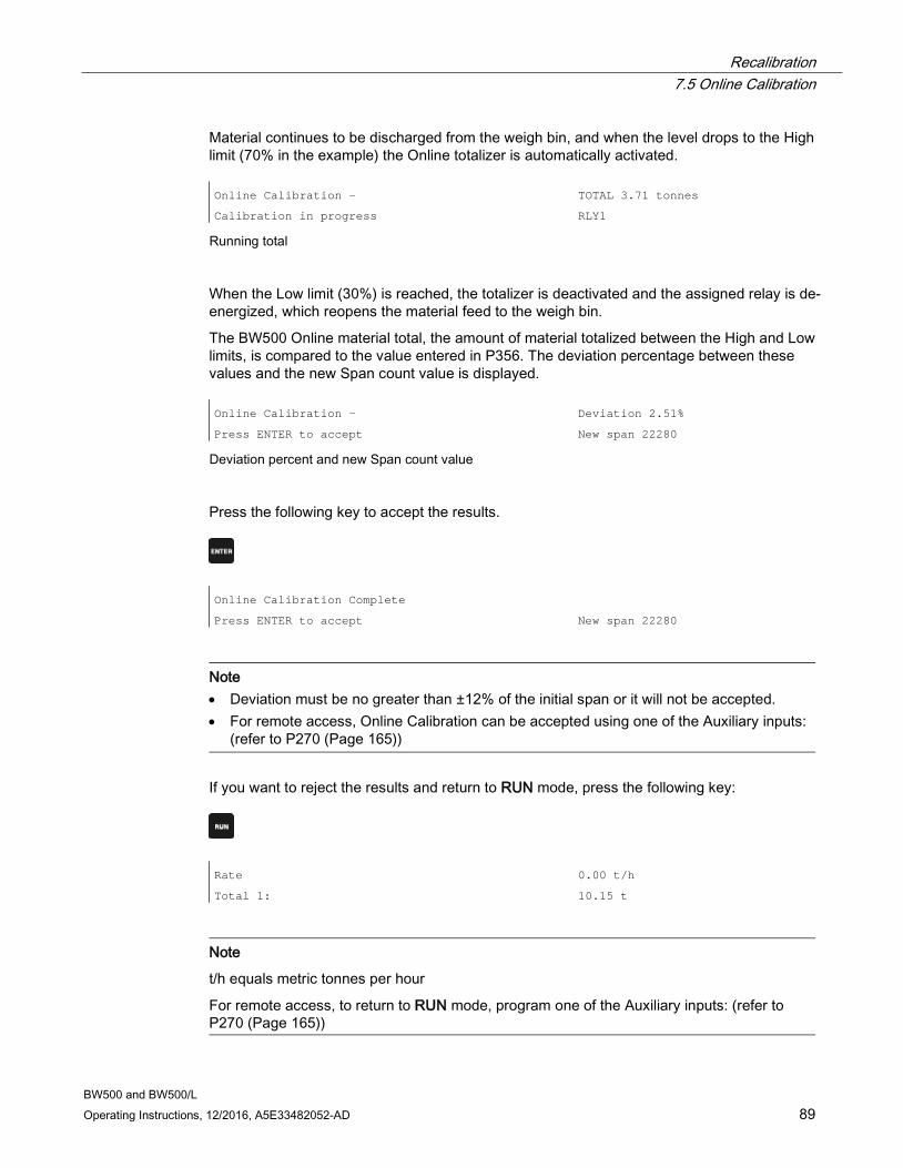
Recalibration 7.5 Online Calibration
BW500 and BW500/L Operating Instructions, 12/2016, A5E33482052-AD 89
Material continues to be discharged from the weigh bin, and when the level drops to the High limit (70% in the example) the Online totalizer is automatically activated. Online Calibration -
Calibration in progress
TOTAL 3.71 tonnes
RLY1
Running total
When the Low limit (30%) is reached, the totalizer is deactivated and the assigned relay is de-energized, which reopens the material feed to the weigh bin.
The BW500 Online material total, the amount of material totalized between the High and Low limits, is compared to the value entered in P356. The deviation percentage between these values and the new Span count value is displayed. Online Calibration -
Press ENTER to accept
Deviation 2.51%
New span 22280
Deviation percent and new Span count value
Press the following key to accept the results.
Online Calibration Complete
Press ENTER to accept
New span 22280
Note • Deviation must be no greater than ±12% of the initial span or it will not be accepted. • For remote access, Online Calibration can be accepted using one of the Auxiliary inputs:
(refer to P270 (Page 165))
If you want to reject the results and return to RUN mode, press the following key:
Rate
Total 1:
0.00 t/h
10.15 t
Note
t/h equals metric tonnes per hour
For remote access, to return to RUN mode, program one of the Auxiliary inputs: (refer to P270 (Page 165))
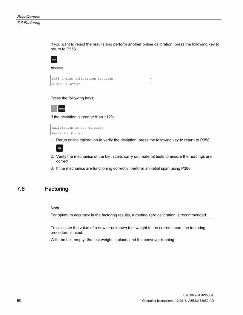
Recalibration 7.6 Factoring
BW500 and BW500/L 90 Operating Instructions, 12/2016, A5E33482052-AD
If you want to reject the results and perform another online calibration, press the following key to return to P358.
Access P358 Online Calibration Features
0-OFF, 1-ACTIVE
V
1
Press the following keys:
If the deviation is greater than ±12%: Calibration is out of range
Deviation Error:
1. Rerun online calibration to verify the deviation: press the following key to return to P358.
2. Verify the mechanics of the belt scale: carry out material tests to ensure the readings are
correct.
3. If the mechanics are functioning correctly, perform an initial span using P388.
7.6 Factoring
Note
For optimum accuracy in the factoring results, a routine zero calibration is recommended.
To calculate the value of a new or unknown test weight to the current span, the factoring procedure is used.
With the belt empty, the test weight in place, and the conveyor running:
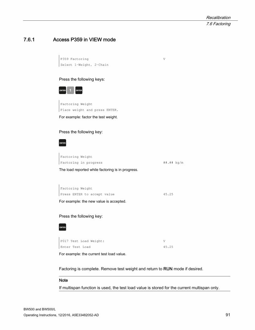
Recalibration 7.6 Factoring
BW500 and BW500/L Operating Instructions, 12/2016, A5E33482052-AD 91
7.6.1 Access P359 in VIEW mode P359 Factoring
Select 1-Weight, 2-Chain
V
Press the following keys:
Factoring Weight
Place weight and press ENTER.
For example: factor the test weight.
Press the following key:
Factoring Weight
Factoring in progress
##.## kg/m
The load reported while factoring is in progress.
Factoring Weight
Press ENTER to accept value
45.25
For example: the new value is accepted.
Press the following key:
P017 Test Load Weight:
Enter Test Load
V
45.25
For example: the current test load value.
Factoring is complete. Remove test weight and return to RUN mode if desired.
Note
If multispan function is used, the test load value is stored for the current multispan only.
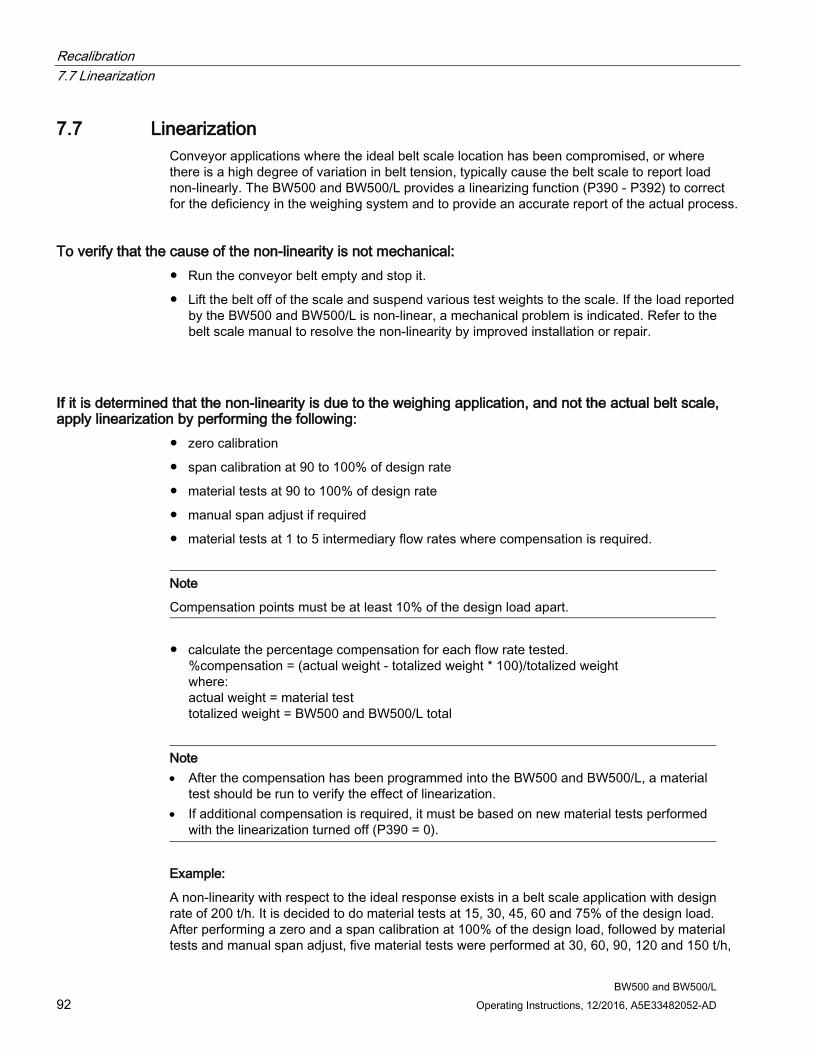
Recalibration 7.7 Linearization
BW500 and BW500/L 92 Operating Instructions, 12/2016, A5E33482052-AD
7.7 Linearization Conveyor applications where the ideal belt scale location has been compromised, or where there is a high degree of variation in belt tension, typically cause the belt scale to report load non-linearly. The BW500 and BW500/L provides a linearizing function (P390 - P392) to correct for the deficiency in the weighing system and to provide an accurate report of the actual process.
To verify that the cause of the non-linearity is not mechanical: ● Run the conveyor belt empty and stop it.
● Lift the belt off of the scale and suspend various test weights to the scale. If the load reported by the BW500 and BW500/L is non-linear, a mechanical problem is indicated. Refer to the belt scale manual to resolve the non-linearity by improved installation or repair.
If it is determined that the non-linearity is due to the weighing application, and not the actual belt scale, apply linearization by performing the following:
● zero calibration
● span calibration at 90 to 100% of design rate
● material tests at 90 to 100% of design rate
● manual span adjust if required
● material tests at 1 to 5 intermediary flow rates where compensation is required.
Note
Compensation points must be at least 10% of the design load apart.
● calculate the percentage compensation for each flow rate tested. %compensation = (actual weight - totalized weight * 100)/totalized weight where: actual weight = material test totalized weight = BW500 and BW500/L total
Note • After the compensation has been programmed into the BW500 and BW500/L, a material
test should be run to verify the effect of linearization. • If additional compensation is required, it must be based on new material tests performed
with the linearization turned off (P390 = 0).
Example:
A non-linearity with respect to the ideal response exists in a belt scale application with design rate of 200 t/h. It is decided to do material tests at 15, 30, 45, 60 and 75% of the design load. After performing a zero and a span calibration at 100% of the design load, followed by material tests and manual span adjust, five material tests were performed at 30, 60, 90, 120 and 150 t/h,

Recalibration 7.7 Linearization
BW500 and BW500/L Operating Instructions, 12/2016, A5E33482052-AD 93
as indicated by the BW500. The following data was tabulated. (This example is exaggerated for emphasis).
The material tests should be run at same belt speed, representative of normal operation; in this case 1.2 m/s. For each rate, record the corresponding load value by scrolling to the BW500 load display during running conditions or by calculation.
load = (rate/speed)
BW500 load material test BW500 total compensationa) kg/m tonnes tonnes % 6.94 2.5 2.8 -10.7
13.89 5.0 4.5 11.1 20.83 7.5 7.9 -5.1 27.78 10.0 9.2 8.7 34.72 12.5 13.3 -6.0
a) calculation example: % compensation = [(2.5 – 2.8) x 100]/2.8 = -10.7
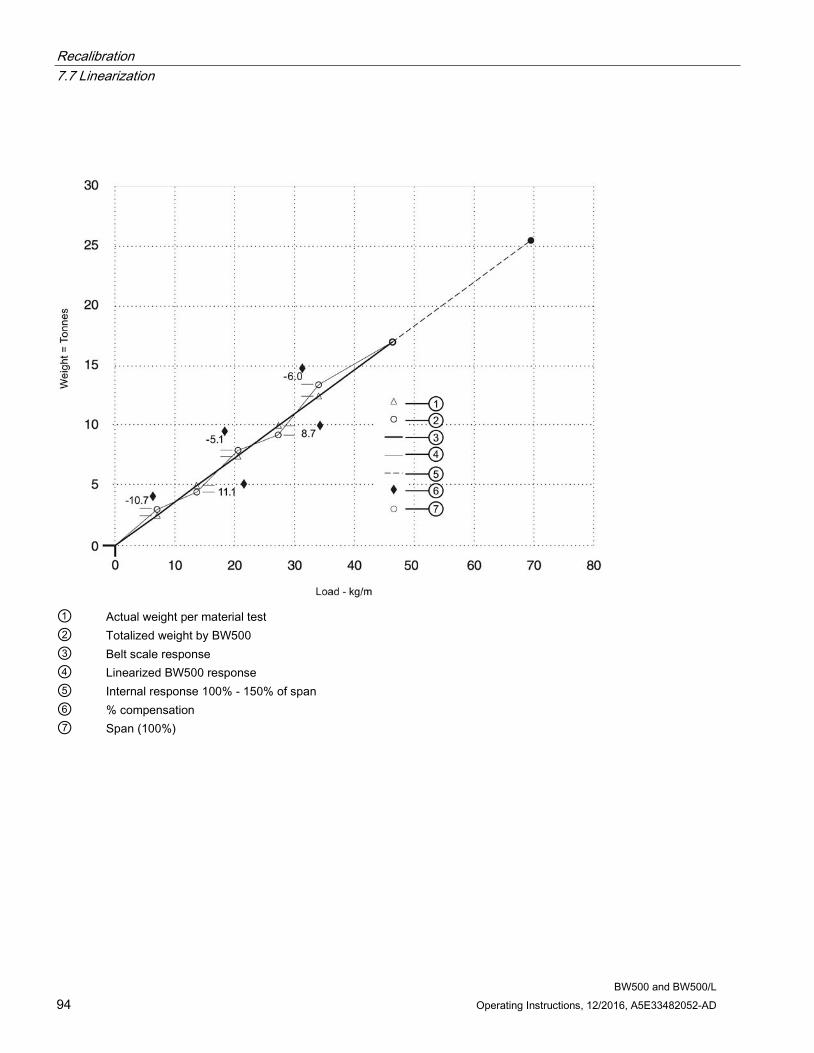
Recalibration 7.7 Linearization
BW500 and BW500/L 94 Operating Instructions, 12/2016, A5E33482052-AD
① Actual weight per material test ② Totalized weight by BW500 ③ Belt scale response ④ Linearized BW500 response ⑤ Internal response 100% - 150% of span ⑥ % compensation ⑦ Span (100%)
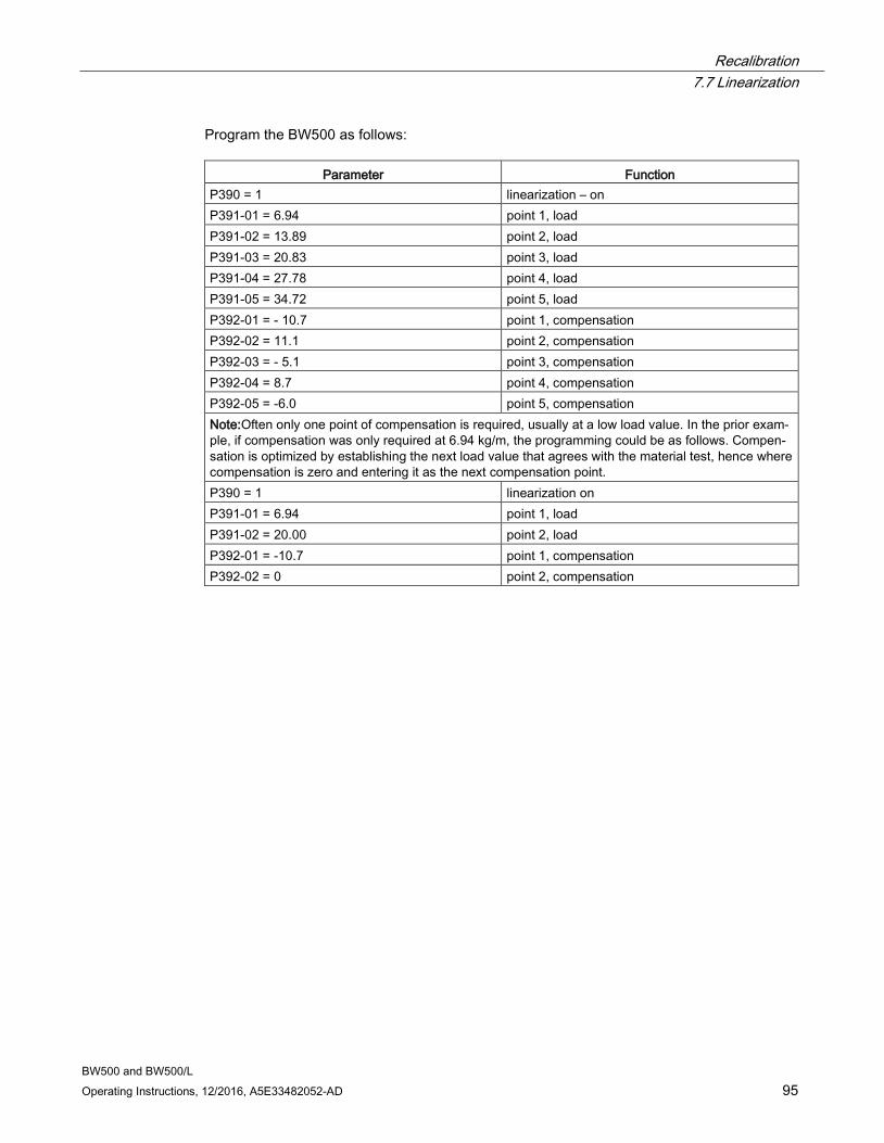
Recalibration 7.7 Linearization
BW500 and BW500/L Operating Instructions, 12/2016, A5E33482052-AD 95
Program the BW500 as follows:
Parameter Function P390 = 1 linearization – on P391-01 = 6.94 point 1, load P391-02 = 13.89 point 2, load P391-03 = 20.83 point 3, load P391-04 = 27.78 point 4, load P391-05 = 34.72 point 5, load P392-01 = - 10.7 point 1, compensation P392-02 = 11.1 point 2, compensation P392-03 = - 5.1 point 3, compensation P392-04 = 8.7 point 4, compensation P392-05 = -6.0 point 5, compensation Note:Often only one point of compensation is required, usually at a low load value. In the prior exam-ple, if compensation was only required at 6.94 kg/m, the programming could be as follows. Compen-sation is optimized by establishing the next load value that agrees with the material test, hence where compensation is zero and entering it as the next compensation point. P390 = 1 linearization on P391-01 = 6.94 point 1, load P391-02 = 20.00 point 2, load P392-01 = -10.7 point 1, compensation P392-02 = 0 point 2, compensation
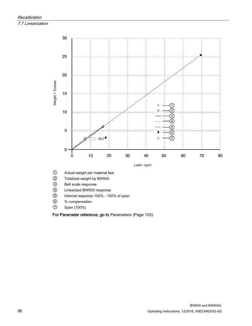
Recalibration 7.7 Linearization
BW500 and BW500/L 96 Operating Instructions, 12/2016, A5E33482052-AD
① Actual weight per material test ② Totalized weight by BW500 ③ Belt scale response ④ Linearized BW500 response ⑤ Internal response 100% - 150% of span ⑥ % compensation ⑦ Span (100%)
For Parameter reference, go to Parameters (Page 153)
BW500 and BW500/L Operating Instructions, 12/2016, A5E33482052-AD 97
Operation 8 8.1 Load Sensing
For the BW500 and BW500/L to calculate rate and totalize material flow along the belt conveyor, a load signal representative of weight of material on the belt is required. The load signal is provided by the belt scale. The BW500 and BW500/L is compatible with belt scales fitted with 1, 2, 4, or 61) strain gauge type load cells. To function with LVDT type sensors, an optional LVDT conditioning card is required.
Refer to Specifications (Page 17), and Installation (Page 21) for belt scale requirements and connection. 1) Not available with BW500/L
8.2 Speed Sensing For the BW500 and BW500/L to calculate rate and totalize material flow along the belt conveyor, a speed signal representative of belt speed is required. For optimum accuracy of the weighing system, and both constant and variable speed applications, a speed sensor is required. The design speed (P014) and speed constant (P015) need to be programmed.
In constant speed applications (no speed sensor), the BW500 can be programmed to provide an internal speed signal. This is achieved by entering the design speed (P014) and providing a contact closure across speed input terminals (17/18). The speed constant (P015) defaults to ‘jumpered’. This contact should change to open when the conveyor is idle to prevent errant totalization.
In applications with two speed sensors, the BW500 can be programmed to provide differential speed. % slip can be calculated, using the difference between the two speed signals with reference to the first speed.2)
Refer to Specifications (Page 17) and Installation (Page 21) for speed sensor requirements and connection. 2) Differential speed detection is not available on the BW500/L.
Operation 8.3 Differential Speed Detection
BW500 and BW500/L 98 Operating Instructions, 12/2016, A5E33482052-AD
8.3 Differential Speed Detection Dual point speed sensing is used for monitoring speed at two points in the system where a difference in speed can be detrimental to the equipment or its operation. The two speed sensors are typically applied on belt conveyors to give an alarm if excessive slip between the head pulley and tail pulley is detected. The secondary speed sensor is especially useful on variable speed conveyors, and may also be used to detect a malfunction in the primary speed sensor.
The BW500 provides a 12 V DC, 150 mA maximum, regulated power supply for both speed sensors. The primary speed sensor is used for all "Run" display integration, and is the reference value for differential speed detection. The primary speed sensor is generally reserved for the driven device (tail pulley). The second speed sensor is generally reserved for the driving device (head pulley), and is used for comparison to the primary speed sensor, for differential speed detection only.
The second speed signal is compared to the primary speed signal, and will initiate an alarm condition if the second speed signal is outside the programmed high and low alarm setpoints.
Connect the second speed sensor as shown in the Installation section (refer to AuxiliarySpeed Sensor), and program the second speed sensor as described in the following steps:
1. Program one of the Auxiliary Inputs as a Speed Sensor input P270-01 to 05 = 16 (Speed Sensor).
2. Program second speed sensors speed constant P015-02 = pulses per meter or foot (Refer to Start Up on page 29, for speed sensor programming).
3. Program one of the alarms for Differential Speed Detection alarm P100-01 to 05 = 10 (Speed Differential).
4. Program the High Alarm setpoint P101-01 to 05 = 110% (default).
5. Program the Low Alarm setpoint P102-01 to 05 = 90% (default).
Note
Differential speed detection is not available on the BW500/L.
8.4 Moisture Compensation Moisture Compensation is used to compensate for the moisture component of the material being weighed. It factors out the moisture component of load, rate and total for all multispans selected. The factored value is meant to report the dry mean values of the material being conveyed.
The BW500 receives the static load cell signal, and adjusts the value of the load being displayed and integrated by the moisture percentage. The mA I/O card is required to accept the mA signal from the Moisture Meter. This mA signal can represent 0 to 100% moisture. The moisture percentage is displayed in P398-01. Using P398-02, the moisture percentage can be represented as a percentage of mass to be deducted from the total mass1). 1) The BW500/L allows for a fixed moisture content to be entered. See “P398-01 Moisture Content (Page 172)”.
Operation 8.5 Incline compensation
BW500 and BW500/L Operating Instructions, 12/2016, A5E33482052-AD 99
Example:
Setting P398-02 = 30% will allow the 4 - 20 mA input to correspond to 0 - 30% moisture.
The Zero and Span calibration is not affected by the presence of a moisture meter. It is understood that the calibrations are performed using dry static weights.
The Moisture Meter must be connected to the appropriate mA input and programmed as described in the following steps:
1. Enable mA input function for moisture compensation P255-01 or 02 = 4 (moisture compensation).
2. Set appropriate mA input range P250-01 or 02 = 2 (default is 4 - 20 mA).
3. Set mA input moisture ratio P398-02 = 100% (default).
4. Observe moisture percentage using P398-01.
8.5 Incline compensation Incline compensation is used to compensate for the varying vertical force component applied to the belt scale due to varying inclination of the conveyor. The BW500 and BW500/L receives the static load cell signal, and adjusts the load displayed and integrated, by a factor of COSINE of the angle of incline.
The Inclinometer should be mounted to the conveyor stringer, parallel to the center of the belt scale. The mA I/O card is required to accept the mA signal from the Inclinometer. This mA signal must represent -30 to 30°. The incline angle is displayed in P399.
The dynamic load cell signal will vary with the incline of the conveyor. The BW500 and BW500/L load display and integration values will remain constant for the given load on the belt scale through the specified range of inclination.
The Zero and Span calibrations of the BW500 and BW500/L will be adjusted based on the angle of incline of the conveyor. The Zero and Span calibration can be performed at any angle. However, if incline compensation will be used, it must be enabled for all Zero and Span calibrations1). 1) The BW500/L allows for a fixed inclined angle to be entered. See “P399 Incline Sensing (Page 173)”.
The Inclinometer must be connected to the appropriate mA input and programmed as described in the following steps:
1. Enable mA input function for incline compensation P255-01 or 02 = 5 (Incline compensation).
2. Set appropriate mA input range P250-01 or 02 = 2 (default is 4 - 20 mA).
3. Observe incline angle using P399.
Operation 8.6 Modes of Operation
BW500 and BW500/L 100 Operating Instructions, 12/2016, A5E33482052-AD
8.6 Modes of Operation RUN is the normal or reference mode of operation. It continuously processes the load and speed signals from the belt scale to produce internal load, speed and rate signals, which are in turn used as the basis for totalization, mA output, relay control, and communication data. The RUN display is programmed (P081) to scroll through rate, totalization (P647), load and speed; either manually by pressing the enter key, or automatically. Rate Total 1
Rate Total 2
Load Speed
If the BW500 is programmed for batch control, the batch display is added to the display scroll. Refer to Batch Control (Page 176) for more information.
From the RUN mode, access to the PROGRAM mode, and zero and span calibration is made.
The PROGRAM mode allows viewing and, with security permission (P000), editing parameter values. During PROGRAM, RUN mode functions are still active, that is.: rate, relay, mA output and totalization.
If the PROGRAM mode is left idle for a period of ten minutes, it automatically reverts to RUN mode.
Zero and span calibrations effectively halt the RUN mode while they are in progress. During this time, totalization ceases, and all mA outputs, except for PID, fall to zero.
8.7 Damping Damping (P080) provides control over the speed at which the displayed readings and output functions respond to changes in their respective input function: load, speed and the internal rate signals. Changes in the displayed rate of material flow, material loading and belt speed are controlled by the damping. Relay alarm functions based on input functions of rate, load and speed, respond to the damped value.
Damping consists of a first order filter applied to the signal (reading or output value).
If mA damping (P220) is enabled (value other than 0), then the damping (P080) as it pertains to the mA function is overridden, and responds independently at the specified mA output damping rate (P220).
Note
Damping (P080 or P220) is not applicable to the mA output when programmed for PID function (P201 = 4).

Operation 8.8 mA I/O (0/4-20 mA)
BW500 and BW500/L Operating Instructions, 12/2016, A5E33482052-AD 101
8.8 mA I/O (0/4-20 mA)
Output The standard BW500 and BW500/L provides one isolated mA output. The output can be assigned (P201) to represent rate, load or speed. The output range can be set to 0 - 20 mA or 4 - 20 mA (P200). The 0 or 4 mA value corresponds to empty or zero condition, whereas the 20 mA value corresponds to the associated design value: rate (P011), load (P952), or speed (P014). The mA output can be limited for over range levels of 0 mA minimum and 22 mA maximum (P212 and P213 respectively). The output 4 and 20 mA levels can also be trimmed (P214 and P215 respectively) to agree with a milliammeter or other external mA device.
The mA output value can be tested to output a prescribed value using parameter P911. Refer to P911 (Page 190). The optional mA I/O board provides two additional mA outputs1), programmable as outputs 2 and 3, using the same parameters as the standard output (1). If programmed for PID control, output 2 is assigned to PID control loop 1 and output 3 is assigned to PID control loop 2. 1) not available with BW500/L
Input The optional mA I/O board provides two mA inputs, programmable as inputs 1 and 2. If programmed for PID control, generally, input 1 is assigned to PID control loop 1 and input 2 is assigned to PID control loop 2.
The input range can be set to 0-20 mA or 4-20 mA (P250), and assigned a function (P255), for example: PID setpoint. The 4 and 20 mA levels can be trimmed (P261 and P262) to agree with an external device. The external device could be a moisture sensor, or an inclinometer.
Note
mA inputs not available with BW500/L

Operation 8.9 Relay Output
BW500 and BW500/L 102 Operating Instructions, 12/2016, A5E33482052-AD
8.9 Relay Output The BW500 offers five single pole single throw (SPST) relays that can be assigned (P100) to one of the following alarm functions, the BW500/L offers two relays of the same type:
● rate: relay alarms on high and/or low material flow rate.
● load: relay alarms on high and/or low belt load.
● speed: relay alarms on high and/or low belt speed.
● differential speed1): relay alarms if second speed signal outside high and/or low alarm setpoints.
● diagnostic: relay alarms on error condition as it is reported. See “Troubleshooting”.
● PID1)2): PID control setpoint deviation
● batch pre-warn1)
● batch setpoint1)
For rate, load, and speed alarm functions, the high and low alarm setpoints (P101 and P102 respectively) are required and must be entered in the appropriate units. The high alarm setpoint acts as the setpoint deviation alarm for relays programmed for PID setpoint deviation.
The on/off actuation at both high and low setpoints is buffered by the damping (P080) and the programmable dead band (P117), to prevent relay chatter due to fluctuations. The relay is normally energized; holding the normally open (n.o.) contact closed (can be programmed for reverse operation, P118). Upon an alarm condition, the relay is deenergized and the relay contact is opened. Once in alarm, the relay remains in alarm state until the alarm condition is removed. 1) Not available with BW500/L 2) Is offered only if the PID system (P400) is enabled.
Example:
P014 = 2m/s, design speed
P100 = 3, belt speed
P101 = 100% (2 m/s)
P102 = 20% (0.4 m/s)
P117 = 2% (0.04 m/s)
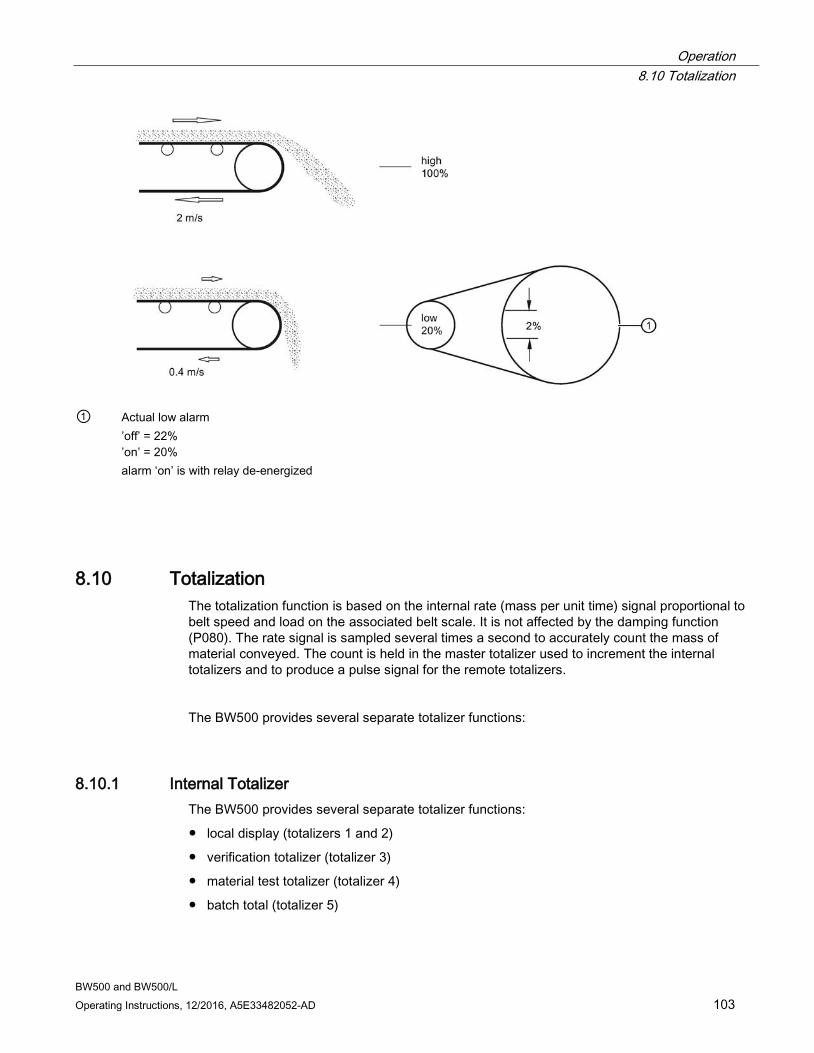
Operation 8.10 Totalization
BW500 and BW500/L Operating Instructions, 12/2016, A5E33482052-AD 103
① Actual low alarm
’off’ = 22% ’on’ = 20% alarm ‘on’ is with relay de-energized
8.10 Totalization The totalization function is based on the internal rate (mass per unit time) signal proportional to belt speed and load on the associated belt scale. It is not affected by the damping function (P080). The rate signal is sampled several times a second to accurately count the mass of material conveyed. The count is held in the master totalizer used to increment the internal totalizers and to produce a pulse signal for the remote totalizers.
The BW500 provides several separate totalizer functions:
8.10.1 Internal Totalizer The BW500 provides several separate totalizer functions:
● local display (totalizers 1 and 2)
● verification totalizer (totalizer 3)
● material test totalizer (totalizer 4)
● batch total (totalizer 5)
Operation 8.10 Totalization
BW500 and BW500/L 104 Operating Instructions, 12/2016, A5E33482052-AD
8.10.2 External Totalizer
● totalizer outputs (remote totalizers 1 and 2)
To avoid totalizing material at flow rates below the low flow rate limit, the totalizer drop out limit (P619) is set to a percentage of the design load. Below this limit, totalization stops. When material flow returns to a rate above the drop out limit, totalization resumes.
Totalizer resolution or count value is set by the respective internal (P631) and external (P638) totalizer1) resolution parameters. 1) If the resolution selected causes the totalizer to lag behind the count rate, the next possible resolution is automatically entered.
Example:
● Internal totalizer 1 Given: P005 = 1 (t/h), P631 = 4 Then: totalizer count increments by 10 for each 10 metric tonnes registered
● External totalizer 1 Given: P005 = 1 (t/h), P638 = 5 Then: contact closure occurs once for every 10 metric tonnes registered
For remote totalization, the contact closure duration (P643) is automatically calculated upon entry of the design rate (P011) and remote totalizer (P638) parameters, so that the duration of contact closure allows the relay response to track the total up to 150% of the design rate. The value can be changed to suit specific contact closure requirements, such as in the case of programmable logic controllers. If the duration selected is inappropriate, the next possible duration is automatically entered.
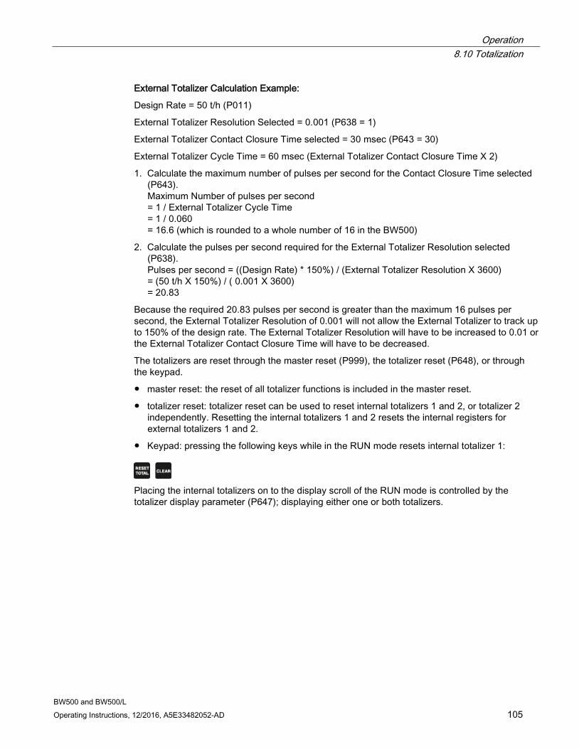
Operation 8.10 Totalization
BW500 and BW500/L Operating Instructions, 12/2016, A5E33482052-AD 105
External Totalizer Calculation Example:
Design Rate = 50 t/h (P011)
External Totalizer Resolution Selected = 0.001 (P638 = 1)
External Totalizer Contact Closure Time selected = 30 msec (P643 = 30)
External Totalizer Cycle Time = 60 msec (External Totalizer Contact Closure Time X 2)
1. Calculate the maximum number of pulses per second for the Contact Closure Time selected (P643). Maximum Number of pulses per second = 1 / External Totalizer Cycle Time = 1 / 0.060 = 16.6 (which is rounded to a whole number of 16 in the BW500)
2. Calculate the pulses per second required for the External Totalizer Resolution selected (P638). Pulses per second = ((Design Rate) * 150%) / (External Totalizer Resolution X 3600) = (50 t/h X 150%) / ( 0.001 X 3600) = 20.83
Because the required 20.83 pulses per second is greater than the maximum 16 pulses per second, the External Totalizer Resolution of 0.001 will not allow the External Totalizer to track up to 150% of the design rate. The External Totalizer Resolution will have to be increased to 0.01 or the External Totalizer Contact Closure Time will have to be decreased.
The totalizers are reset through the master reset (P999), the totalizer reset (P648), or through the keypad.
● master reset: the reset of all totalizer functions is included in the master reset.
● totalizer reset: totalizer reset can be used to reset internal totalizers 1 and 2, or totalizer 2 independently. Resetting the internal totalizers 1 and 2 resets the internal registers for external totalizers 1 and 2.
● Keypad: pressing the following keys while in the RUN mode resets internal totalizer 1:
Placing the internal totalizers on to the display scroll of the RUN mode is controlled by the totalizer display parameter (P647); displaying either one or both totalizers.

Operation 8.10 Totalization
BW500 and BW500/L 106 Operating Instructions, 12/2016, A5E33482052-AD
BW500 and BW500/L Operating Instructions, 12/2016, A5E33482052-AD 107
PID Control 9
The PID control algorithm in the BW500 is designed specifically to work for feed rate control applications. It is based on motor control type algorithms and includes several anti-wind up provisions.
One way to prevent wind up is to monitor the input speed frequency from the weighfeeder. If the input frequency drops below 5 Hz, the PID control output freezes at its current value. Otherwise, the output winds up to 100% if the feeder is shut off while there is still a set point greater than zero. When the feeder is turned back on, there would be a surge of product flow until the system regains stability. With anti-wind up, the feeder can be stopped and started with minimal disruption to the controlled flow rate.
To operate the BW500 as a controller, address the following:
● hardware
● connections
● setup and tuning
● programming
Note
PID control not available on the BW500/L.
9.1 Hardware For the BW500 to operate as a controller, install the optional mA I/O board. Refer to Installation (Page 21).
9.2 Connections Connections to process instruments, in addition to standard operating connections, must be made.
Refer to:
● Installation (Page 21), specifically:
● Relay Output (Page 40), for relay connections
● mA I/O board (Page 43), for mA input and output connections
● Auxiliary Inputs (Page 38), for optional remote control
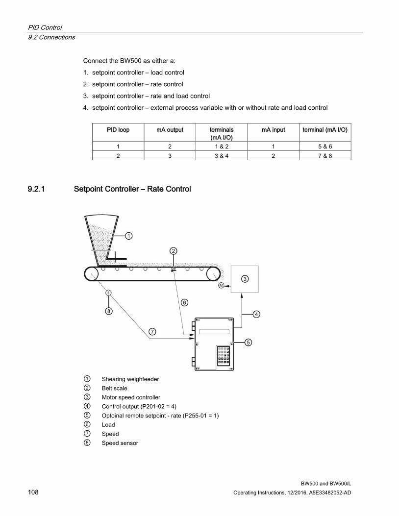
PID Control 9.2 Connections
BW500 and BW500/L 108 Operating Instructions, 12/2016, A5E33482052-AD
Connect the BW500 as either a:
1. setpoint controller – load control
2. setpoint controller – rate control
3. setpoint controller – rate and load control
4. setpoint controller – external process variable with or without rate and load control
PID loop mA output terminals (mA I/O)
mA input terminal (mA I/O)
1 2 1 & 2 1 5 & 6 2 3 3 & 4 2 7 & 8
9.2.1 Setpoint Controller – Rate Control
① Shearing weighfeeder ② Belt scale ③ Motor speed controller ④ Control output (P201-02 = 4) ⑤ Optoinal remote setpoint - rate (P255-01 = 1) ⑥ Load ⑦ Speed ⑧ Speed sensor
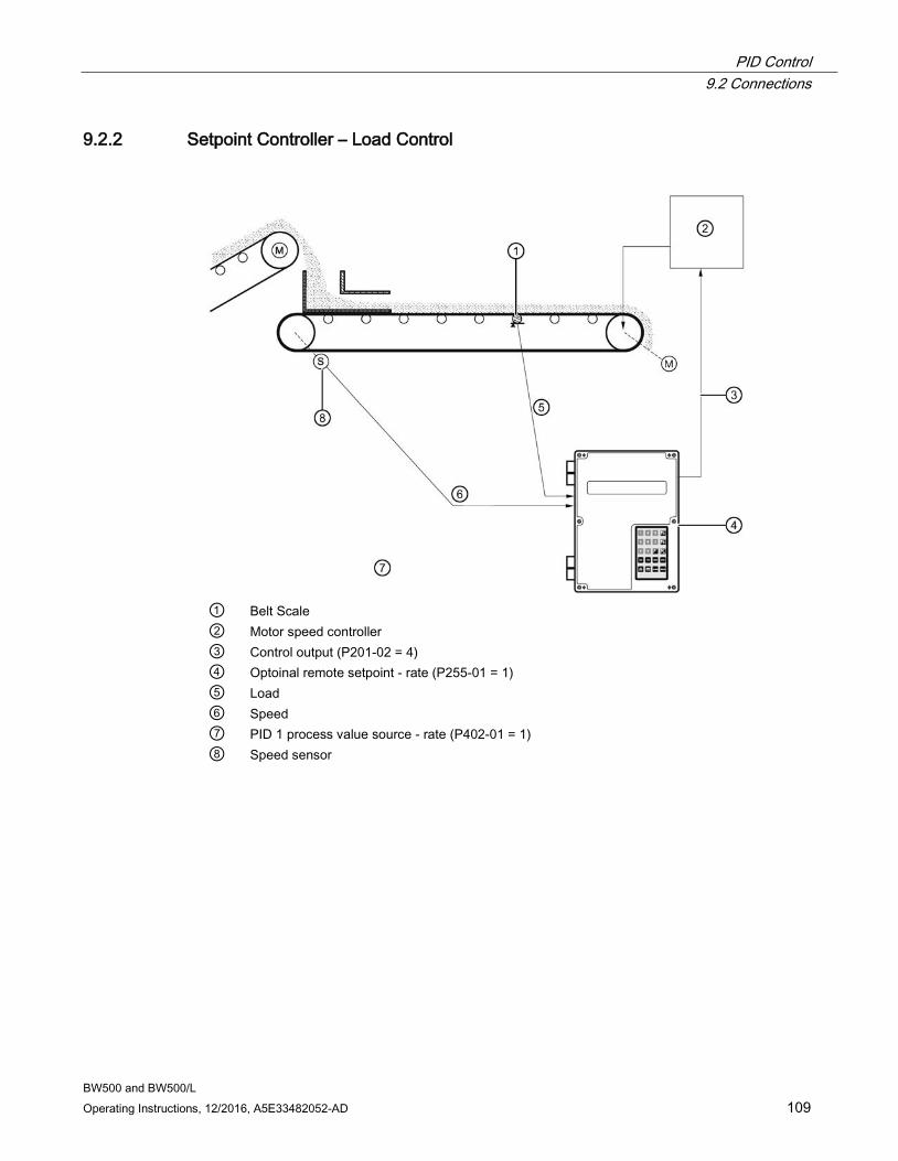
PID Control 9.2 Connections
BW500 and BW500/L Operating Instructions, 12/2016, A5E33482052-AD 109
9.2.2 Setpoint Controller – Load Control
① Belt Scale ② Motor speed controller ③ Control output (P201-02 = 4) ④ Optoinal remote setpoint - rate (P255-01 = 1) ⑤ Load ⑥ Speed ⑦ PID 1 process value source - rate (P402-01 = 1) ⑧ Speed sensor
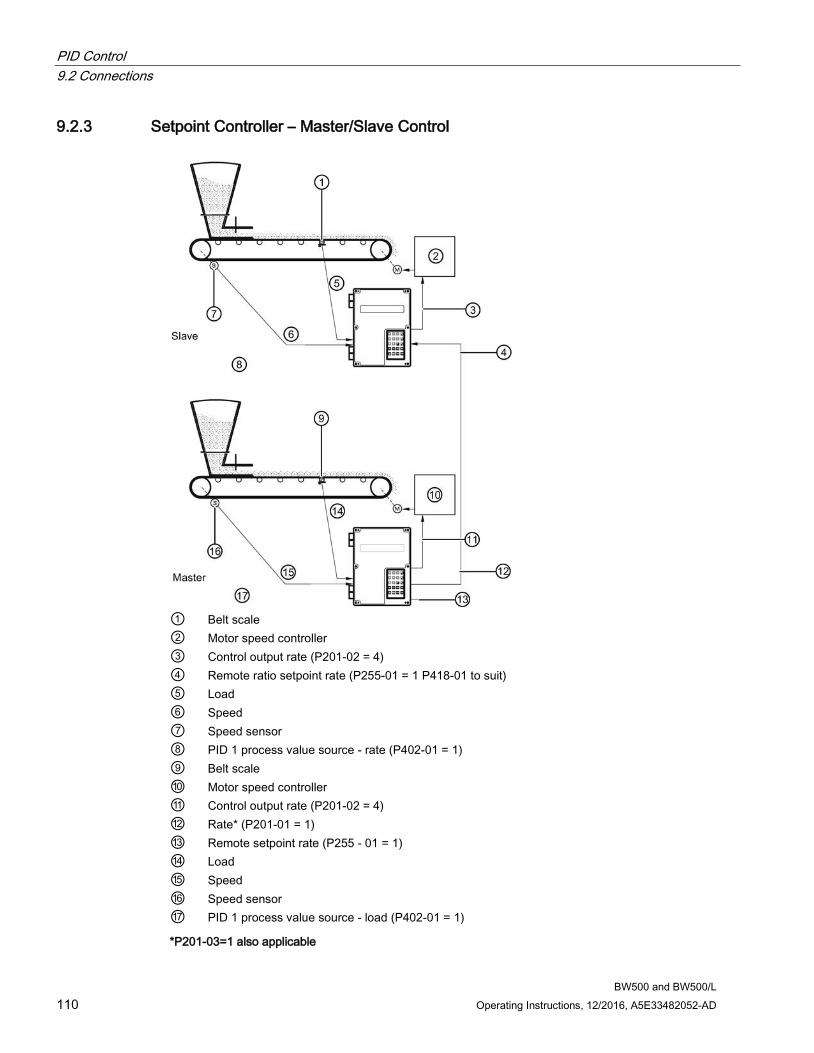
PID Control 9.2 Connections
BW500 and BW500/L 110 Operating Instructions, 12/2016, A5E33482052-AD
9.2.3 Setpoint Controller – Master/Slave Control
① Belt scale ② Motor speed controller ③ Control output rate (P201-02 = 4) ④ Remote ratio setpoint rate (P255-01 = 1 P418-01 to suit) ⑤ Load ⑥ Speed ⑦ Speed sensor ⑧ PID 1 process value source - rate (P402-01 = 1) ⑨ Belt scale ⑩ Motor speed controller ⑪ Control output rate (P201-02 = 4) ⑫ Rate* (P201-01 = 1) ⑬ Remote setpoint rate (P255 - 01 = 1) ⑭ Load ⑮ Speed ⑯ Speed sensor ⑰ PID 1 process value source - load (P402-01 = 1)
*P201-03=1 also applicable
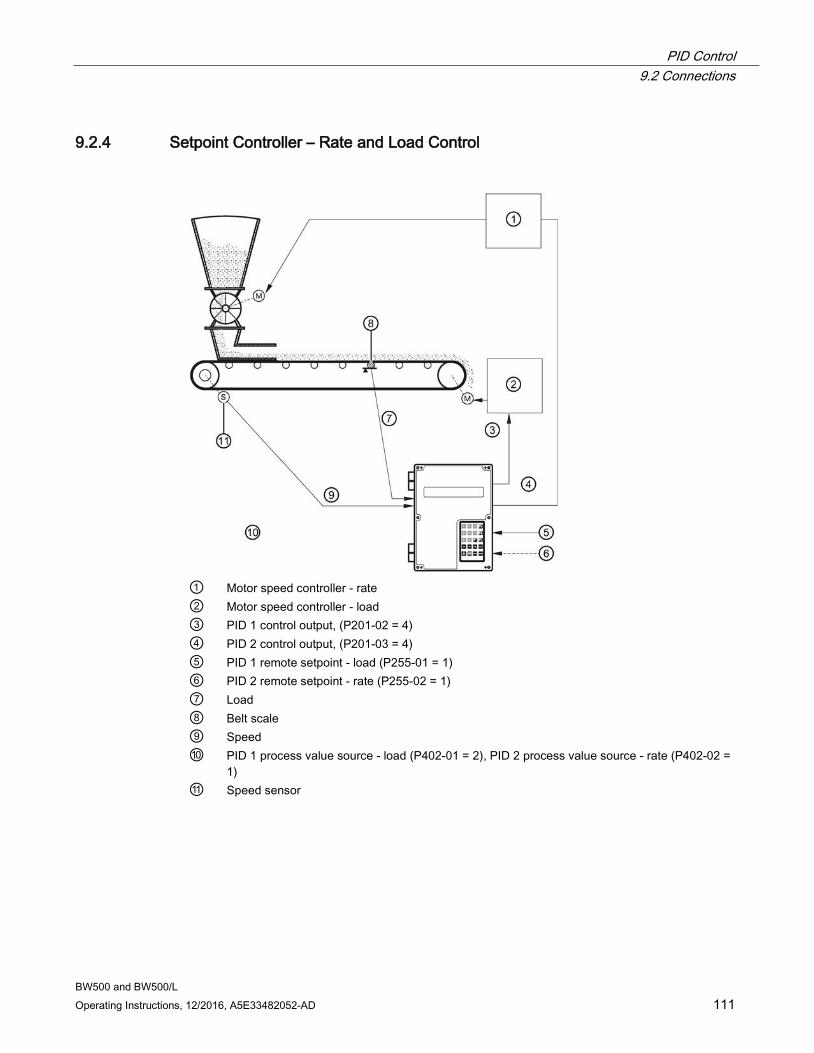
PID Control 9.2 Connections
BW500 and BW500/L Operating Instructions, 12/2016, A5E33482052-AD 111
9.2.4 Setpoint Controller – Rate and Load Control
① Motor speed controller - rate ② Motor speed controller - load ③ PID 1 control output, (P201-02 = 4) ④ PID 2 control output, (P201-03 = 4) ⑤ PID 1 remote setpoint - load (P255-01 = 1) ⑥ PID 2 remote setpoint - rate (P255-02 = 1) ⑦ Load ⑧ Belt scale ⑨ Speed ⑩ PID 1 process value source - load (P402-01 = 2), PID 2 process value source - rate (P402-02 =
1) ⑪ Speed sensor
PID Control 9.3 Setup and Tuning
BW500 and BW500/L 112 Operating Instructions, 12/2016, A5E33482052-AD
9.3 Setup and Tuning Before proceeding, it would be beneficial to qualify and quantify the terms you will encounter in the setup and tuning of the control system.
9.3.1 Proportional Control (Gain), P The P term on the BW500 adjusts the control output based on the difference between the set point and the measured flow rate. A higher P term makes the BW500 more sensitive and faster to react to changes or disturbances. If set too high, the BW500 becomes less stable, and more susceptible to oscillations in the control output.
● allowable input range: 0.000 to 2.000
● typical operating range: 0.300 to 0.600
● default value: 0.400
The control output cannot reach the setpoint using only the P term. Since the P term acts on the difference between the setpoint and process variable, a small difference between these two always exist and the difference is never zero. A small P term can get the process very close to set point, but it would take a very long time. At the very least, an Iterm is required to eliminate the offset created by the P term.
9.3.2 Integral Control (Automatic Reset), I The I term on the BW500 is used to increase or reduce the amount of control output to eliminate the offset caused by the P term. The I term acts on the accumulation of the error over small increments of time. As the process reaches setpoint and the error becomes small, the effect of the I term decreases. A higher I term makes the BW500 faster to react to changes, but can also make it less stable.
● allowable input range: 0.000 to 2.000
● typical operating range: 0.100 to 0.300
● default value: 0.200
The P and I terms together can make a suitable control algorithm and for many applications, they work fine. However, if faster response to changes is desired, it is necessary to use larger P and I terms. Unfortunately, larger terms can make the system unstable. A derivative term is needed to influence the control output as the process variable approaches the set point.
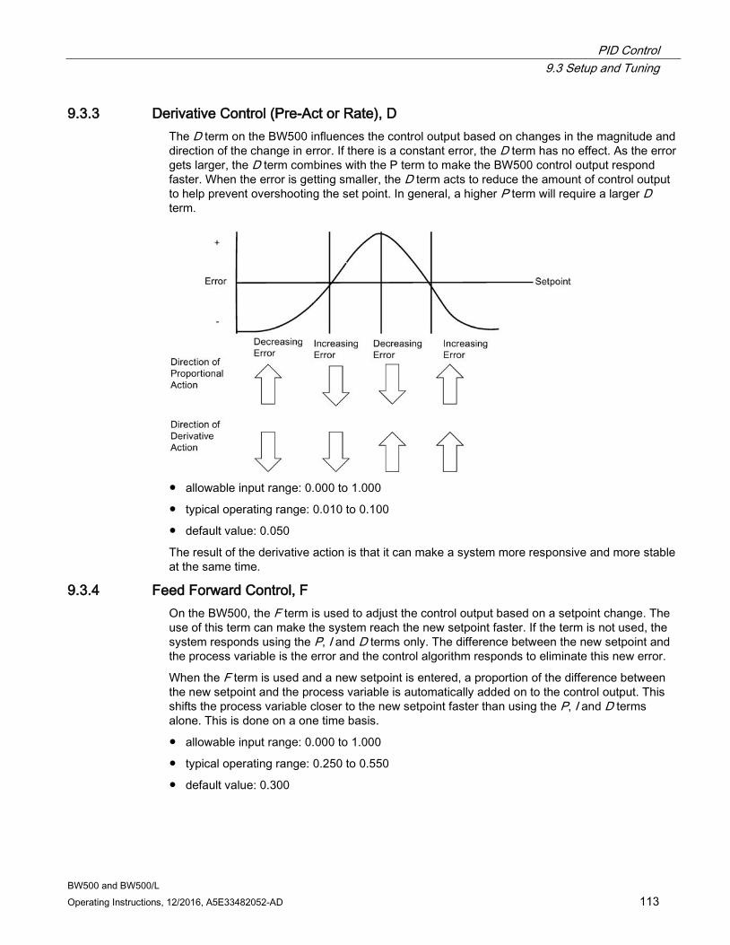
PID Control 9.3 Setup and Tuning
BW500 and BW500/L Operating Instructions, 12/2016, A5E33482052-AD 113
9.3.3 Derivative Control (Pre-Act or Rate), D The D term on the BW500 influences the control output based on changes in the magnitude and direction of the change in error. If there is a constant error, the D term has no effect. As the error gets larger, the D term combines with the P term to make the BW500 control output respond faster. When the error is getting smaller, the D term acts to reduce the amount of control output to help prevent overshooting the set point. In general, a higher P term will require a larger D term.
● allowable input range: 0.000 to 1.000
● typical operating range: 0.010 to 0.100
● default value: 0.050
The result of the derivative action is that it can make a system more responsive and more stable at the same time.
9.3.4 Feed Forward Control, F On the BW500, the F term is used to adjust the control output based on a setpoint change. The use of this term can make the system reach the new setpoint faster. If the term is not used, the system responds using the P, I and D terms only. The difference between the new setpoint and the process variable is the error and the control algorithm responds to eliminate this new error.
When the F term is used and a new setpoint is entered, a proportion of the difference between the new setpoint and the process variable is automatically added on to the control output. This shifts the process variable closer to the new setpoint faster than using the P, I and D terms alone. This is done on a one time basis.
● allowable input range: 0.000 to 1.000
● typical operating range: 0.250 to 0.550
● default value: 0.300
PID Control 9.4 PID Setup and Tuning
BW500 and BW500/L 114 Operating Instructions, 12/2016, A5E33482052-AD
The PID control function of the BW500 can be configured to operate in several modes.
● controller output: direct acting
● feedback: rate, load, or external
● control: local or remote (ratio) setpoint
9.4 PID Setup and Tuning Proper tuning of the control PID terms is essential to system operation and optimum performance from the feeder. The recommended procedures for tuning the PID control terms at initial start-up are described in this section.
9.4.1 Initial Start-Up Although the default values of the P, I, D, and F terms will suit the majority of applications, shearing weigh feeders in particular, some tuning will be necessary nonetheless.
There are several techniques and procedures for tuning conventional PID controllers, some work better depending upon the application. We recommend using "closed-loop cycling" for the BW500 integrator/controller for feed rate control. This technique focuses on tuning the P term first while disabling the I and D terms. This is followed by adding andtuning the I term, then the D term. To outline this procedure:
1. With the P term set to its default value of 0.400, disable the I, D, and F terms by setting them to 0.000.
2. Enter a feed rate setpoint that is 30% of the designed maximum flow rate.
3. Having applied the test weights or chain provided, start the feeder and observe the time it takes the feeder to reach setpoint, also observe the oscillation around setpoint.
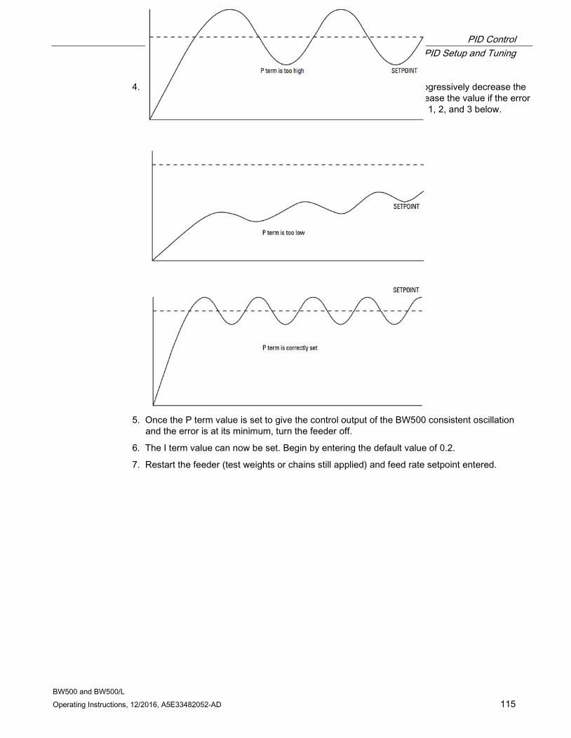
PID Control 9.4 PID Setup and Tuning
BW500 and BW500/L Operating Instructions, 12/2016, A5E33482052-AD 115
4. Adjust the P term accordingly for consistent oscillation and error. Progressively decrease the P term value if there is too much oscillation and error. Likewise, increase the value if the error is not consistent and oscillating around the setpoint. Refer to figures 1, 2, and 3 below.
5. Once the P term value is set to give the control output of the BW500 consistent oscillation
and the error is at its minimum, turn the feeder off.
6. The I term value can now be set. Begin by entering the default value of 0.2.
7. Restart the feeder (test weights or chains still applied) and feed rate setpoint entered.
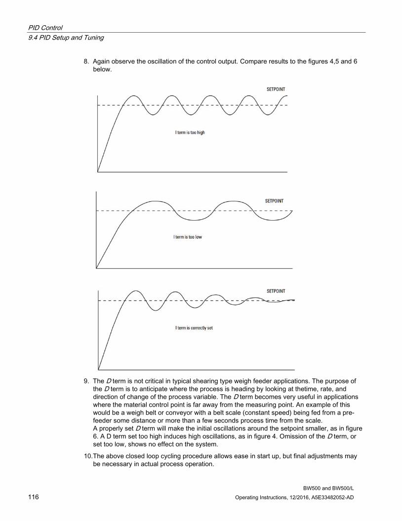
PID Control 9.4 PID Setup and Tuning
BW500 and BW500/L 116 Operating Instructions, 12/2016, A5E33482052-AD
8. Again observe the oscillation of the control output. Compare results to the figures 4,5 and 6 below.
9. The D term is not critical in typical shearing type weigh feeder applications. The purpose of
the D term is to anticipate where the process is heading by looking at thetime, rate, and direction of change of the process variable. The D term becomes very useful in applications where the material control point is far away from the measuring point. An example of this would be a weigh belt or conveyor with a belt scale (constant speed) being fed from a pre-feeder some distance or more than a few seconds process time from the scale. A properly set D term will make the initial oscillations around the setpoint smaller, as in figure 6. A D term set too high induces high oscillations, as in figure 4. Omission of the D term, or set too low, shows no effect on the system.
10.The above closed loop cycling procedure allows ease in start up, but final adjustments may be necessary in actual process operation.

PID Control 9.5 Programming
BW500 and BW500/L Operating Instructions, 12/2016, A5E33482052-AD 117
9.5 Programming The BW500 is software ready, however the controller function must be specifically programmed in addition to programming of parameters P001 through P017.
The BW500 offers programming for two separate PID controls, 1 and 2. The controller being programmed is identified by the suffix to the parameter number. e.g. P400-01 indicates that PID for control system 1 is accessed.
Note
All programming should be done in the PID manual mode.
Access P400-01 PID System E
Select: 0-Off, 1-Manual, 2-Auto 0
Select 1-manual to program PID parameters
Off disables the PID parameter set, P401 to P418. They are not accessible.
Manual: the control output is the manual output P410.
Auto: engages the PID controller function. This can also be done using the following key:
Note
For the mA output: • mA output 2 (P201-02) is normally reserved for controller 1. The signal is output at
terminals 1 and 2 on the mA I/O board. • mA output 3 (P201-03) is normally reserved for controller 2. The signal is output at
terminals 3 and 4 on the mA I/O board.
P201-02 mA Output Function E
Select: 1-Rate, 2-Load, 3-Speed, 4-PID 1
Select the PID function.
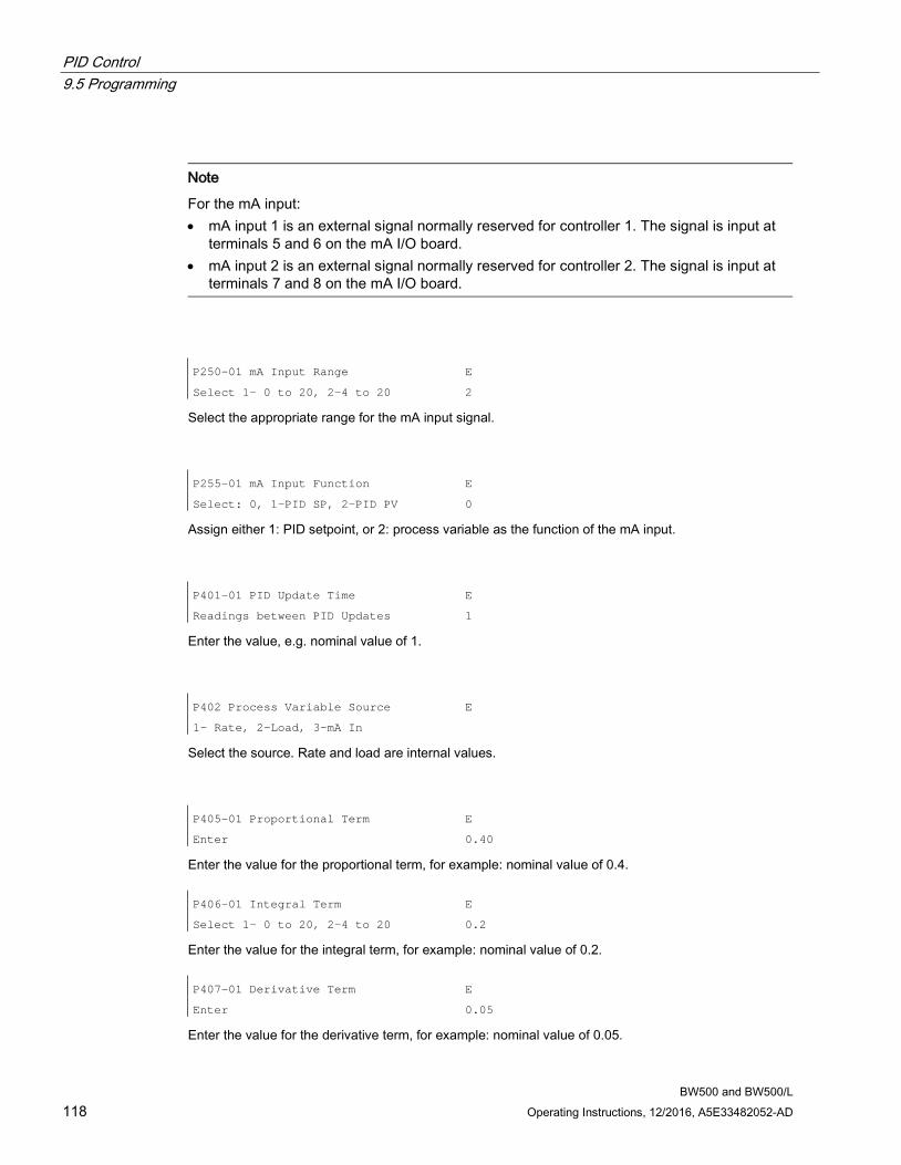
PID Control 9.5 Programming
BW500 and BW500/L 118 Operating Instructions, 12/2016, A5E33482052-AD
Note
For the mA input: • mA input 1 is an external signal normally reserved for controller 1. The signal is input at
terminals 5 and 6 on the mA I/O board. • mA input 2 is an external signal normally reserved for controller 2. The signal is input at
terminals 7 and 8 on the mA I/O board.
P250-01 mA Input Range E
Select 1- 0 to 20, 2-4 to 20 2
Select the appropriate range for the mA input signal.
P255-01 mA Input Function E
Select: 0, 1-PID SP, 2-PID PV 0
Assign either 1: PID setpoint, or 2: process variable as the function of the mA input.
P401-01 PID Update Time E
Readings between PID Updates 1
Enter the value, e.g. nominal value of 1.
P402 Process Variable Source E
1- Rate, 2-Load, 3-mA In
Select the source. Rate and load are internal values.
P405-01 Proportional Term E
Enter 0.40
Enter the value for the proportional term, for example: nominal value of 0.4. P406-01 Integral Term E
Select 1- 0 to 20, 2-4 to 20 0.2
Enter the value for the integral term, for example: nominal value of 0.2. P407-01 Derivative Term E
Enter 0.05
Enter the value for the derivative term, for example: nominal value of 0.05.
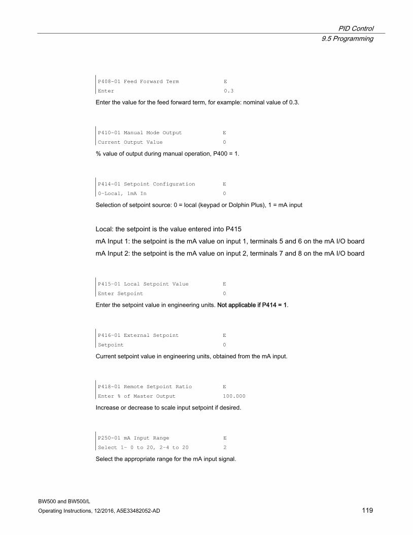
PID Control 9.5 Programming
BW500 and BW500/L Operating Instructions, 12/2016, A5E33482052-AD 119
P408-01 Feed Forward Term E
Enter 0.3
Enter the value for the feed forward term, for example: nominal value of 0.3.
P410-01 Manual Mode Output E
Current Output Value 0
% value of output during manual operation, P400 = 1.
P414-01 Setpoint Configuration E
0-Local, 1mA In 0
Selection of setpoint source: 0 = local (keypad or Dolphin Plus), 1 = mA input
Local: the setpoint is the value entered into P415
mA Input 1: the setpoint is the mA value on input 1, terminals 5 and 6 on the mA I/O board
mA Input 2: the setpoint is the mA value on input 2, terminals 7 and 8 on the mA I/O board
P415-01 Local Setpoint Value E
Enter Setpoint 0
Enter the setpoint value in engineering units. Not applicable if P414 = 1.
P416-01 External Setpoint E
Setpoint 0
Current setpoint value in engineering units, obtained from the mA input.
P418-01 Remote Setpoint Ratio E
Enter % of Master Output 100.000
Increase or decrease to scale input setpoint if desired.
P250-01 mA Input Range E
Select 1- 0 to 20, 2-4 to 20 2
Select the appropriate range for the mA input signal.
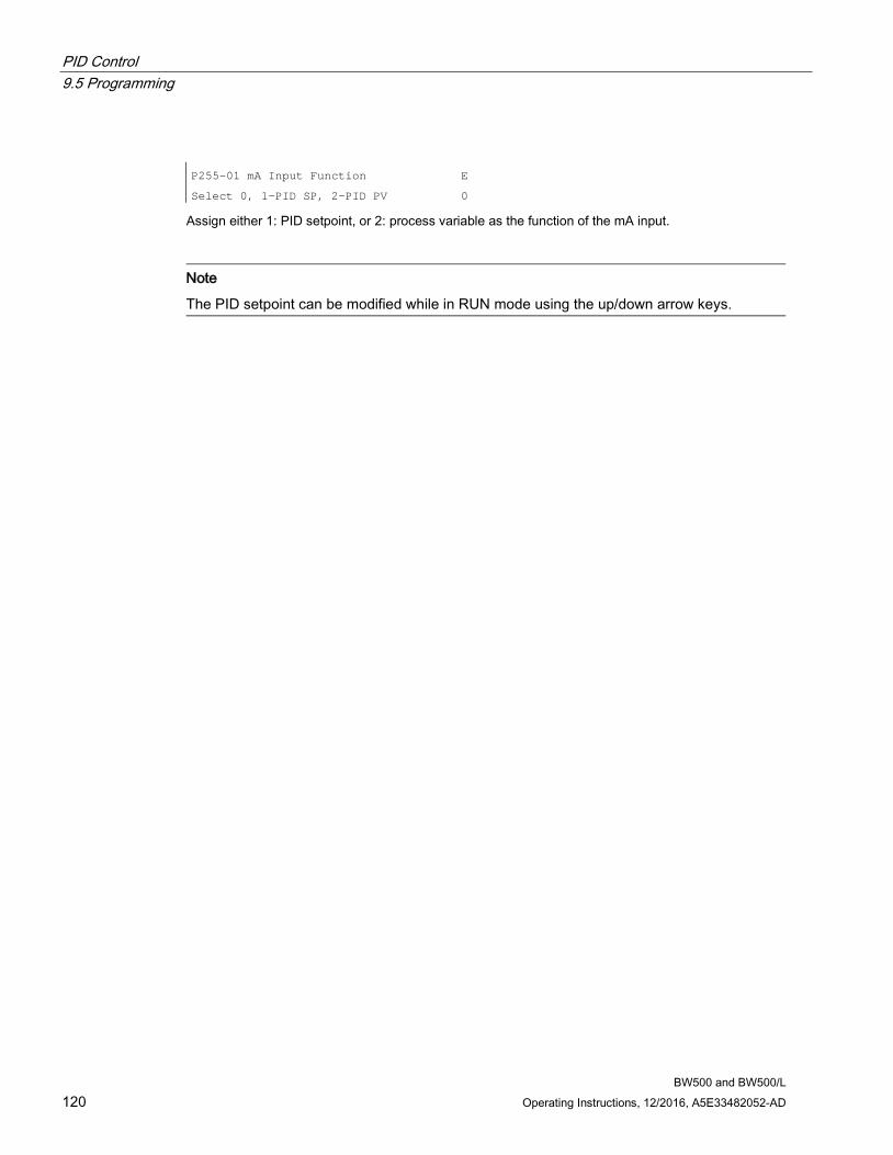
PID Control 9.5 Programming
BW500 and BW500/L 120 Operating Instructions, 12/2016, A5E33482052-AD
P255-01 mA Input Function E
Select 0, 1-PID SP, 2-PID PV 0
Assign either 1: PID setpoint, or 2: process variable as the function of the mA input.
Note
The PID setpoint can be modified while in RUN mode using the up/down arrow keys.
BW500 and BW500/L Operating Instructions, 12/2016, A5E33482052-AD 121
Batching 10
The batching process, as it relates to the BW500 operation, can be defined as the transfer of a predetermined quantity of material.
The process supports a count up operation (P560), in that the total (totalizer 5) begins at zero and increments up to the programmed setpoint (P564). A relay (RL1 through 5) programmed as the batch setpoint function (P100 = 8) is actuated when the material total reaches the setpoint. The relay contact acts as an interlock to the material feed to end the batch.
Another relay can be programmed as a pre-warn alarm (P100 = 7), to alert the process that batch end is near. The relay is actuated when the material total reaches the prewarn setpoint (P567) at some practical value below the batch setpoint. The pre-warn function is enabled/disabled from the batch process through P566.
For batch operations, the following must be addressed:
● Connections
● Programming
● Operation
Note
Not available on the BW500/L
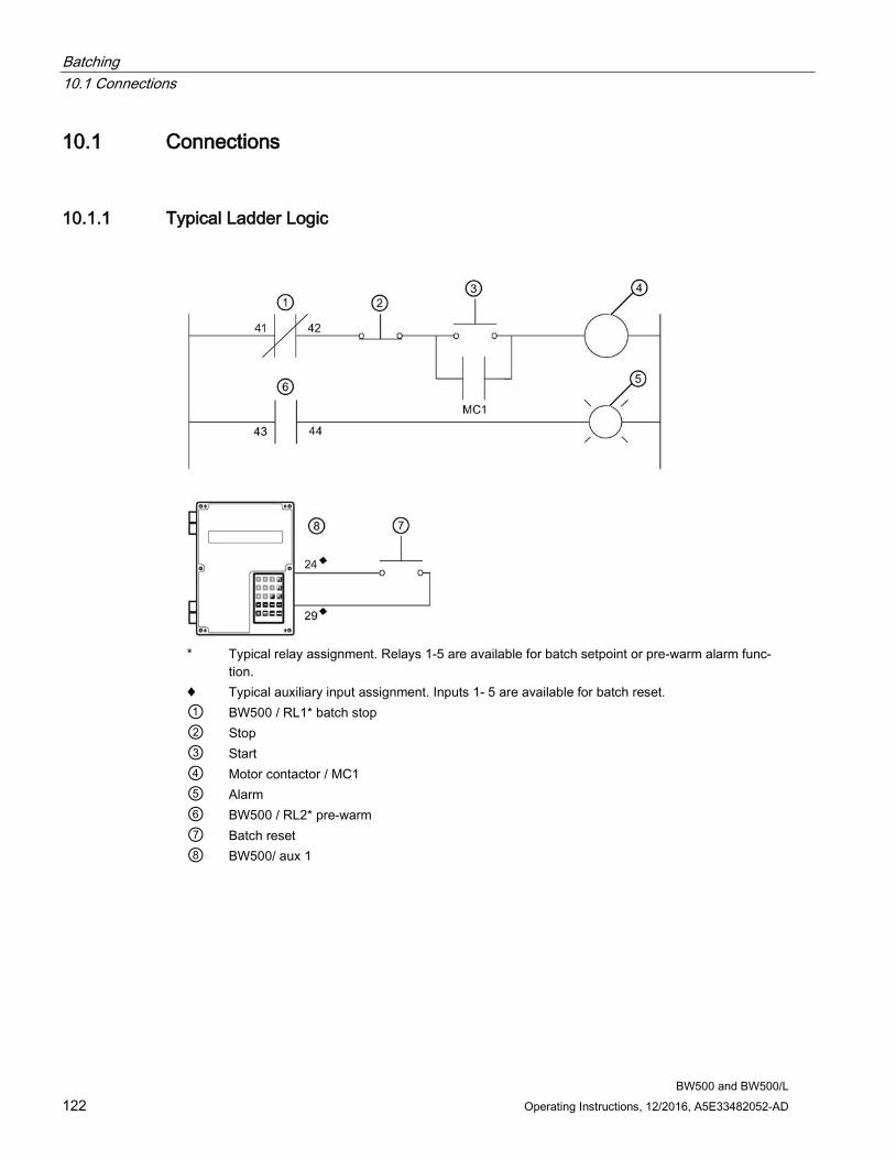
Batching 10.1 Connections
BW500 and BW500/L 122 Operating Instructions, 12/2016, A5E33482052-AD
10.1 Connections
10.1.1 Typical Ladder Logic
* Typical relay assignment. Relays 1-5 are available for batch setpoint or pre-warm alarm func-
tion. ♦ Typical auxiliary input assignment. Inputs 1- 5 are available for batch reset. ① BW500 / RL1* batch stop ② Stop ③ Start ④ Motor contactor / MC1 ⑤ Alarm ⑥ BW500 / RL2* pre-warm ⑦ Batch reset ⑧ BW500/ aux 1
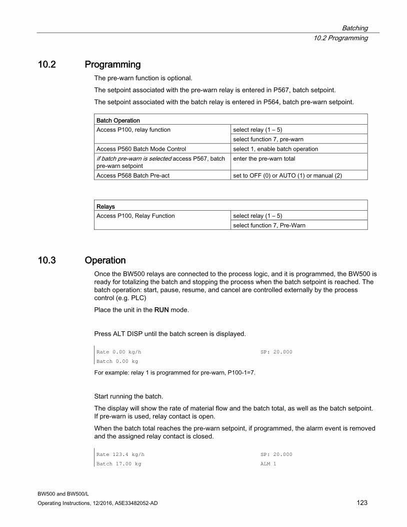
Batching 10.2 Programming
BW500 and BW500/L Operating Instructions, 12/2016, A5E33482052-AD 123
10.2 Programming The pre-warn function is optional.
The setpoint associated with the pre-warn relay is entered in P567, batch setpoint.
The setpoint associated with the batch relay is entered in P564, batch pre-warn setpoint. Batch Operation Access P100, relay function select relay (1 – 5)
select function 7, pre-warn Access P560 Batch Mode Control select 1, enable batch operation if batch pre-warn is selected access P567, batch pre-warn setpoint
enter the pre-warn total
Access P568 Batch Pre-act set to OFF (0) or AUTO (1) or manual (2)
Relays Access P100, Relay Function select relay (1 – 5)
select function 7, Pre-Warn
10.3 Operation Once the BW500 relays are connected to the process logic, and it is programmed, the BW500 is ready for totalizing the batch and stopping the process when the batch setpoint is reached. The batch operation: start, pause, resume, and cancel are controlled externally by the process control (e.g. PLC)
Place the unit in the RUN mode.
Press ALT DISP until the batch screen is displayed. Rate 0.00 kg/h
Batch 0.00 kg
SP: 20.000
For example: relay 1 is programmed for pre-warn, P100-1=7.
Start running the batch.
The display will show the rate of material flow and the batch total, as well as the batch setpoint. If pre-warn is used, relay contact is open.
When the batch total reaches the pre-warn setpoint, if programmed, the alarm event is removed and the assigned relay contact is closed. Rate 123.4 kg/h SP: 20.000
Batch 17.00 kg ALM 1
Batching 10.3 Operation
BW500 and BW500/L 124 Operating Instructions, 12/2016, A5E33482052-AD
The process continues, and when the batch total reaches the batch setpoint, the alarm event is displayed and the assigned relay is actuated (contact opened). Typically the relay contact would be integrated into the batch control logic to end the process.
Rate 123.4 kg/h
Batch 20.00 kg
ALM 12
Relay 2 is programmed for batch setpoint, P100-2=8.
When the next batch is to be run, pressing the following keys then on the local keypad, or providing a momentary contact closure across an auxiliary input (programmed as batch reset, P270 = 8), sets the alarm display and resets the batch total to zero, and the relay contact to its closed state.
Rate 0.00 kg/h
Batch 0.00 kg
SP: 20.000
Note
The batch setpoint can be modified in RUN mode using the up/down arrow keys.
10.3.1 Pre-act Function If repetitive batches are being run, the pre-act function (P568) can be enabled to automatically trip the setpoint relay before or after the batch setpoint is reached to assure best batch accuracy.
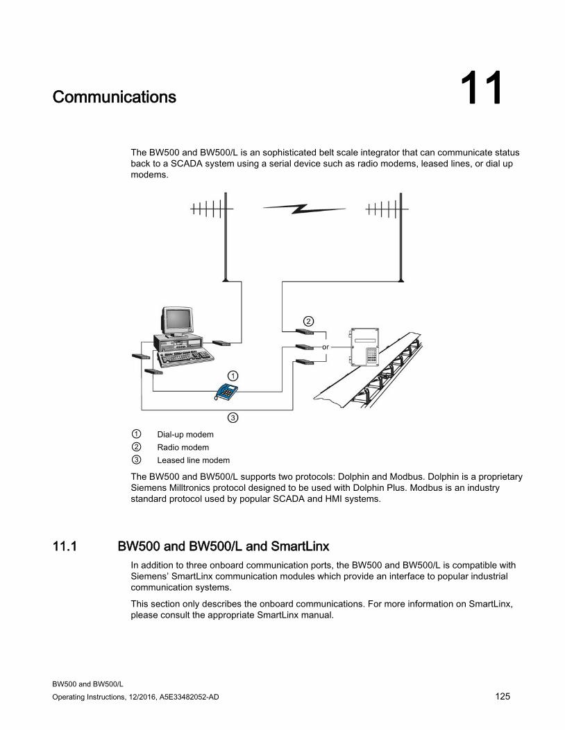
BW500 and BW500/L Operating Instructions, 12/2016, A5E33482052-AD 125
Communications 11
The BW500 and BW500/L is an sophisticated belt scale integrator that can communicate status back to a SCADA system using a serial device such as radio modems, leased lines, or dial up modems.
① Dial-up modem ② Radio modem ③ Leased line modem
The BW500 and BW500/L supports two protocols: Dolphin and Modbus. Dolphin is a proprietary Siemens Milltronics protocol designed to be used with Dolphin Plus. Modbus is an industry standard protocol used by popular SCADA and HMI systems.
11.1 BW500 and BW500/L and SmartLinx In addition to three onboard communication ports, the BW500 and BW500/L is compatible with Siemens’ SmartLinx communication modules which provide an interface to popular industrial communication systems.
This section only describes the onboard communications. For more information on SmartLinx, please consult the appropriate SmartLinx manual.
Communications 11.2 Connections
BW500 and BW500/L 126 Operating Instructions, 12/2016, A5E33482052-AD
11.2 Connections
WARNING
When a SmartLinx card is installed and P799 = 1, the parameters that the SmartLinx card is writing to the BW500 and BW500/L will be continuously updated. Therefore, if you connect a SmartLinx card to the BW500, set P799 = 1 and not write anything to the SmartLinx card, your setpoints will be 0.
There are three serial communication ports on the BW500 and BW500/L:
Port Description 1 RS-232, Terminals 31 to 34 2 RS-485, terminals 35 to 40 3 RS-232, RJ-11 modular telephone jack
Refer to the Installation (Page 21) for wiring diagrams specific to each port.
11.2.1 Wiring Guidelines Improper wiring and choice of cables are the most common sources of communication problems. Listed below are some suggested guidelines:
• 15 meters (50 feet) for RS-232
• 1200 meters (4000 feet) for RS-485
• Ensure that communication cable is run separately from power and control cables (i.e. do not tie wrap your RS-232 cable to the power cable or have them in the same conduit).
• cable is shielded and connected to ground at one end only
• 24 AWG (minimum)
• follow proper grounding guidelines for all devices on the bus
• use good quality communication grade (shielded twisted pairs) cable that is recommended for RS-232.
Communications 11.3 Configuring Communication Ports
BW500 and BW500/L Operating Instructions, 12/2016, A5E33482052-AD 127
11.3 Configuring Communication Ports The BW500 and BW500/L communications ports are setup by a series of parameters (P770 – P789) which are indexed by port.
The communication parameters are indexed to the following:
Port Description 1 RS-232, Terminals 31 to 34 2 RS-485, terminals 35 to 40 3 RS-232, RJ-11 modular telephone
f indicates the factory setting.
Note
Changes to these parameters are not effected until the power to the unit is turned off and then back on.
11.3.1 P770 Serial protocols The communications protocol used between the BW500 and BW500/L and other devices for the selected port, ports 1 to 3 (P770-01 to –03).
The BW500 and BW500/L supports Siemens Milltronics’ proprietary “Dolphin” data format, as well as the internationally recognized Modbus standard in both ASCII and RTU formats. It also supports direct connection of a printer.
The Siemens protocol is compatible with the Dolphin Plus configuration program. See the Siemens web site for information on this PC product (http://www.siemens.com/processautomation (http://www.siemens.com/processautomation)).
The Modbus protocol is an open standard developed by AEG Schneider Automation Inc. Specifications are available from their web site (http://www.modicon.com/ (http://www.modicon.com/)).
Other protocols are available with optional SmartLinx cards.
Values
0f (01 and 02) communications disabled
1f (03) Siemens Milltronics "Dolphin" protocol
2 Modbus ASCII slave serial protocol
3 Modbus RTU slave serial protocol
4 printer
Note
BW500 and BW500/L must be in RUN mode to allow for the print operation.
Communications 11.3 Configuring Communication Ports
BW500 and BW500/L 128 Operating Instructions, 12/2016, A5E33482052-AD
11.3.2 P771 Protocol address
Note
Applicable only to ports programmed for Modbus RTU or Modbus ASCII (P770).
The unique identifier of the BW500 and BW500/L on the network for the selected port, ports 1 to 3 (P771-01 to -03).
For devices connected with the Siemens Milltronics protocol this parameter is ignored. For devices connected with a serial Modbus protocol this parameter is a number from 1- 247. It is up to the network administrator to ensure that all devices on the network have unique addresses.
Do not use the value “0” for Modbus communications as this is the broadcast address and is inappropriate for a slave device.
Values
0 to 9999 (f = 1)
11.3.3 P772 Baud Rate The communication rate with the master device for the selected port, ports 1 to 3 (P772- 01 to –03).
The baud rate chosen should reflect the speed of the connected hardware and protocol used.
Values
1f (01 and 02) 4800 baud
2 9600 baud
3f (03) 19,200 baud
11.3.4 P773 Parity The serial port parity for the selected port, ports 1 to 3 (P773-01 to –03).
Ensure that the communications parameters are identical between the BW500 and BW500/L and all connected devices.
For example many modems default to N-8-1 which is: No parity, 8 data bits, and 1 stop bit.
Values
0f none
1 even
2 odd
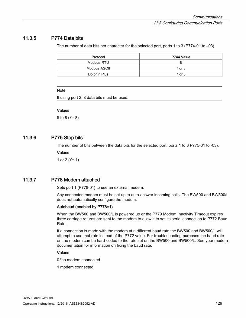
Communications 11.3 Configuring Communication Ports
BW500 and BW500/L Operating Instructions, 12/2016, A5E33482052-AD 129
11.3.5 P774 Data bits The number of data bits per character for the selected port, ports 1 to 3 (P774-01 to –03).
Protocol P744 Value Modbus RTU 8
Modbus ASCII 7 or 8 Dolphin Plus 7 or 8
Note
If using port 2, 8 data bits must be used.
Values
5 to 8 (f = 8)
11.3.6 P775 Stop bits The number of bits between the data bits for the selected port, ports 1 to 3 P775-01 to -03).
Values
1 or 2 (f = 1)
11.3.7 P778 Modem attached Sets port 1 (P778-01) to use an external modem.
Any connected modem must be set up to auto-answer incoming calls. The BW500 and BW500/L does not automatically configure the modem.
Autobaud (enabled by P778=1)
When the BW500 and BW500/L is powered up or the P779 Modem Inactivity Timeout expires three carriage returns are sent to the modem to allow it to set its serial connection to P772 Baud Rate.
If a connection is made with the modem at a different baud rate the BW500 and BW500/L will attempt to use that rate instead of the P772 value. For troubleshooting purposes the baud rate on the modem can be hard-coded to the rate set on the BW500 and BW500/L. See your modem documentation for information on fixing the baud rate.
Values
0f no modem connected
1 modem connected
Communications 11.3 Configuring Communication Ports
BW500 and BW500/L 130 Operating Instructions, 12/2016, A5E33482052-AD
11.3.8 P779 Modem idle time Sets the time in seconds that the BW500 and BW500/L will keep the modem connected even though no activity is happening.
To use this parameter ensure that P778=1.
This parameter allows for reconnection to the BW500 and BW500/L unit after an unexpected disconnect. Ensure that the value is low enough to avoid unnecessary delays when an unexpected disconnect occurs but long enough to avoid timeout while you are still legitimately connected.
Hanging Up
If the line is idle and the P779 Modem Inactivity Timeout expires then the modem is directed to hang up the line. This is done with the Hayes commands:
● two second delay
● +++
● two second delay
● ATH
Ensure that P779 is set longer than the standard polling time of the connected master device.
0 disables the inactivity timer.
Values
0-9999: 0 (f = 1)
11.3.9 P780 RS-232 Transmission interval
Note
Applicable only to ports programmed for printer communication (P770).
Sets the interval between transmissions to be applied to the selected port, ports 1 to 3 (P780-01 to –03).
Enter the period in minutes (f = 0)
Communications 11.3 Configuring Communication Ports
BW500 and BW500/L Operating Instructions, 12/2016, A5E33482052-AD 131
11.3.10 P781 Data message
Note
Applicable only to ports programmed for printer communication (P770).
Sets the data message to be delivered via the selected port, ports 1 to 3 (P781-01 to -03). All messages and printouts include time and date2).
Entry:
0f = no message
1 = rate
2 = total1)
3 = load
4 = speed
5 = rate, total1), load and speed
6 = rate and total1)
7 = batching2)
8 = rate and speed
9 = quick start parameters (P001 – P017)
10 = all parameters 1) Totalizer 1 and/or 2 as set by P647, Totalizer Display. 2) Not available with BW500/L
11.3.11 P799 Communications Control Assigns programming control either locally through the keypad or Dolphin Plus (P770 = 1), or remotely through Modbus protocol (P770 = 2 or 3) or SmartLinx.
Entry:
0 = local
1 = remote
WARNING
When a SmartLinx card is installed and P799 = 1, the parameters that the SmarlLinx card is writing to the BW500 and BW500/L will be continuously updated. Therefore, if you connect a SmartLinx card to the BW500 and BW500/L, set P799 = 1 and not write anything to the SmarLinx card, your setpoints will be zero.
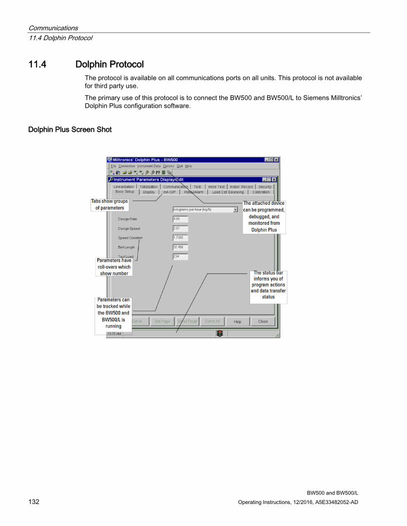
Communications 11.4 Dolphin Protocol
BW500 and BW500/L 132 Operating Instructions, 12/2016, A5E33482052-AD
11.4 Dolphin Protocol The protocol is available on all communications ports on all units. This protocol is not available for third party use.
The primary use of this protocol is to connect the BW500 and BW500/L to Siemens Milltronics’ Dolphin Plus configuration software.
Dolphin Plus Screen Shot
Communications 11.5 Modbus RTU/ASCII Protocol
BW500 and BW500/L Operating Instructions, 12/2016, A5E33482052-AD 133
11.5 Modbus RTU/ASCII Protocol Modbus is an industry standard protocol owned by Schneider Automation Inc.1) and is used throughout process control industries for communication between devices. Modbus RTU and Modbus ASCII are both master-slave type protocols. BW500 and BW500/L’s Modbus is a slave unit.
BW500 and BW500/L supports both the RTU and ASCII version of Modbus and attempts to automatically detect the type when a connection is made.
Note • host should wait at least 500 ms between a message polls to the BW500 and BW500/L • for Modbus RTU, the host should wait at least 1000 ms for a response from the BW500
and BW500/L. In Modbus ASCII mode the suggested timeout is 1500 ms.
1) Modicon is a registered trademark of Groupe Schneider.
A brief description of Modbus RTU and Modbus ASCII is given in this manual. For a full description of the Modbus protocol, contact your local Schneider representative. Also you may try their web site at:
http://www.modicon.com/ (http://www.modicon.com/)
At the time of publication of this manual, the Modbus Protocol was located under products / technical publications / communications products / Modbus protocol.
Note
Siemens does not own the Modbus RTU protocol. All information regarding that protocol is subject to change without notice.
11.5.1 How Modbus Works As mentioned above, Modbus is a master-slave type protocol. This can also be referred to as a query-response protocol. What both of these terms mean is that on the network, there is one master which requests information from multiple slave devices. The slave devices are not permitted to talk unless they have been asked for information. When responding, the slaves will either give the information that the master has requested or give an error code consisting of why it cannot give the information or that it did not understand the request. Refer to Error Handling (Page 149).
All BW500 and BW500/L information is mapped into the Modbus holding registers so that Modbus function code 03 can read from them and Modbus function code 06 and 16 can write to them.
Communications 11.5 Modbus RTU/ASCII Protocol
BW500 and BW500/L 134 Operating Instructions, 12/2016, A5E33482052-AD
11.5.2 Modbus RTU vs. ASCII There are two main differences between Modbus RTU and Modbus ASCII. The first is that Modbus RTU encodes the message in 8-bit binary, while ASCII encodes the message in ASCII characters. Therefore, one byte of information would be encoded into 8 bits for RTU and into two ASCII characters for ASCII (which would be two 7-bit units). The second difference is that the error checking method is different (see below).
Modbus RTU has the advantage that it has a much greater data throughput than ASCII. Modbus ASCII has the advantage that it allows time intervals of up to one second to occur between characters without causing an error. Either protocol works with the BW500 and BW500/L.
11.5.3 Modbus Format
Note
When using a commercial Modbus driver all of the message details are handled for you.
To give you a better idea of how a Modbus message works, a master on network would send a message in a format similar to this:
Station address Function code Information Error check
Where: Station address the network address of the slave being ac-
cessed Function Code number that represent a Modbus command,
either: 03 read function 06, 16 write functions
Information depends on function code Error Check Cyclical Redundancy Check (CRC) for RTU
and Longitudinal Redundancy Check (LRC) for ASCII
There is more to the frame than is described above, this is shown to give the user a general idea of what is going on. For a full description, refer to the Modbus specifications.
11.5.4 Modbus Register Map The memory map of the BW500 and BW500/L occupies the Modbus holding registers (R40,001 and up).
The BW500 and BW500/L was designed to make it easy for users to get useful information via Modbus. The following chart gives an overview of the different sections.

Communications 11.5 Modbus RTU/ASCII Protocol
BW500 and BW500/L Operating Instructions, 12/2016, A5E33482052-AD 135
Register Map for BW500 and BW500/L Map Legend Description Type: Arbitrary classification of registers. Description: Brief description or title of associated register. Start: Provides the starting address for the register(s)
where the parameter values are to be read from or written to.
Number R: The number of registers required to read or write the complete parameter value. Where the num-ber of registers (6) are addressed in incrementing sequence from the start register.
Parameter Values: Refer to Parameter Values. Read: Identifies the read / write capability for the regis-
ter being addressed. Reference: Provides reference documentation for the register
being addressed.
Type Description Start # R Parameter Values
Read Reference
Format Format Word for 32 bit variables
40,062 1 0 - 1 r/w Refer to Modbus Register Map (cont’d) section given below.
ID Device Iden-tifier
40,064 1 2 r Refer to Modbus Register Map (cont’d) section given below.
Handshak-ing Area (Parameter Access)
Parameter 40,090 1 0-999 r/w Refer to the Modbus Register Map (cont’d) section given below.
Primary Index
40,091 1 0 - 9 r/w
Secondary Index
40,092 1 0 - 9 r/w
Format Word
40,093 1 bit mapped r/w
Read Value (word 1)
40,094 2 32 bits r
Write Value (word 1)
40,096 2 32 bits r/w
Date and Timea)
YYYY 41,000 1 1996-2069 r/w Refer to the Date and MM 41,001 1 1 - 12 r/w

Communications 11.5 Modbus RTU/ASCII Protocol
BW500 and BW500/L 136 Operating Instructions, 12/2016, A5E33482052-AD
Type Description Start # R Parameter Values
Read Reference
DD 41,002 1 1 - 31 r/w Time (R41,000 – 41,006) section given below and also P008 (Page 154)
hh 41,003 1 00 - 23 r/w Refer to the Date and Time (R41,000 – 41,006) section given below and also P009 (Page 155)
mm 41,004 1 00 - 59 r/w ss 41,005 1 00 - 59 r/w
Time Zone 41,006 1 -12 - 12 r/w see P739 (Page 186)
Process Values
Rate 41,010 2 32 bits r Refer to the Process Values (R41,010 – R41,048) section given below.
Load 41,012 32 bits r Speed 41,014 2 32 bits r Total 1 41,016 2 32 bits r Total 2 41,018 2 32 bits r
Device State 41,020 1 bit mapped r Refer to the Process Values (R41,010 – R41,048) section given below.
Command Control
41,022 1 bit mapped r/w Refer to Command Controls (41,022) given below.
Multi-Span Selection
41,024 1 1 - 8 r/w Refer to Multispan (Page 81) and P365 (Page 170).
Total 1 dec-imal places
41,025 1 1 - 3 r/w Refer to Read/Write (R41,025 – R41,026)
Total 2 dec-imal places
41,026 1 1 - 3 r/w
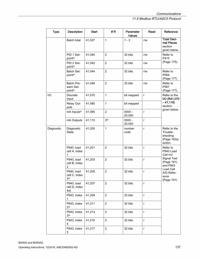
Communications 11.5 Modbus RTU/ASCII Protocol
BW500 and BW500/L Operating Instructions, 12/2016, A5E33482052-AD 137
Type Description Start # R Parameter Values
Read Reference
Batch total 41,027 1 1 - 3 r/w Total Deci-mal Places section given below.
PID 1 Set-pointa)
41,040 2 32 bits r/w Refer to P415 (Page 175). PID 2 Set-
pointa) 41,042 2 32 bits r/w
Batch Set-pointa)
41,044 2 32 bits r/w Refer to P564. (Page 177)
Batch Pre-warn Set-pointa)
41,046 2 32 bits r/w Refer to P567 (Page 177).
I/O Discrete Input
41,070 1 bit mapped r Refer to the I/O (R41,070 – 41,116) section given below.
Relay Out-puts
41,080 1 bit mapped
mA Inputsa) 41,090 2 0000 - 20,000
r
mA Outputs 41,110 3b) 0000 - 20,000
r
Diagnostic Diagnostic State
41,200 1 number code
r Refer to the Trouble-shooting (Page 193)section.
P940, load cell A, index 1
41,201 2 32 bits r Refer to P940 Load Cell mV Signal Test (Page 191) and P943 Load Cell A/D Refer-ence (Page 191)
P940, load cell B, index 2
41,203 2 32 bits r
P940, load cell C, index 3a)
41,205 2 32 bits r
P940, load cell D, index 4a)
41,207 2 32 bits r
P943, index 1
41,209 2 32 bits r
P943, index 2a)
41,211 2 32 bits r
P943, index 3a)
41,213 2 32 bits r
P943, index 4
41,215 2 32 bits r
P943, index 5
41,217 2 32 bits r
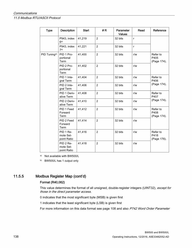
Communications 11.5 Modbus RTU/ASCII Protocol
BW500 and BW500/L 138 Operating Instructions, 12/2016, A5E33482052-AD
Type Description Start # R Parameter Values
Read Reference
P943, index 6a)
41,219 2 32 bits r
P943, index 7a)
41,221 2 32 bits r
PID Tuninga) PID 1 Pro-portional Term
41,400 2 32 bits r/w Refer to P405 (Page 174).
PID 2 Pro-portional Term
41,402 2 32 bits r/w
PID 1 Inte-gral Term
41,404 2 32 bits r/w Refer to P406 (Page 174). PID 2 Inte-
gral Term 41,406 2 32 bits r/w
PID 1 Deriv-ative Term
41,408 2 32 bits r/w Refer to P407 (Page 174). PID 2 Deriv-
ative Term 41,410 2 32 bits r/w
PID 1 Feed Forward Term
41,412 2 32 bits r/w Refer to P408 (Page 174).
PID 2 Feed Forward Term
41,414 2 32 bits r/w
PID 1 Re-mote Set-point Ratio
41,416 2 32 bits r/w Refer to P418 (Page 176).
PID 2 Re-mote Set-point Ratio
41,418 2 32 bits r/w
a) Not available with BW500/L b) BW500/L has 1 output only
11.5.5 Modbus Register Map (cont’d) Format (R40,062)
This value determines the format of all unsigned, double-register integers (UINT32), except for those in the direct parameter access. 0 indicates that the most significant byte (MSB) is given first
1 indicates that the least significant byte (LSB) is given first
For more information on this data format see page 108 and also P742 Word Order Parameter
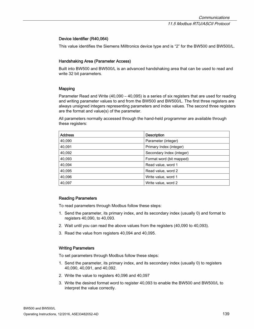
Communications 11.5 Modbus RTU/ASCII Protocol
BW500 and BW500/L Operating Instructions, 12/2016, A5E33482052-AD 139
Device Identifier (R40,064)
This value identifies the Siemens Milltronics device type and is “2” for the BW500 and BW500/L.
Handshaking Area (Parameter Access)
Built into BW500 and BW500/L is an advanced handshaking area that can be used to read and write 32 bit parameters.
Mapping
Parameter Read and Write (40,090 – 40,095) is a series of six registers that are used for reading and writing parameter values to and from the BW500 and BW500/L. The first three registers are always unsigned integers representing parameters and index values. The second three registers are the format and value(s) of the parameter.
All parameters normally accessed through the hand-held programmer are available through these registers: Address Description 40,090 Parameter (integer) 40,091 Primary Index (integer) 40,092 Secondary Index (integer) 40,093 Format word (bit mapped) 40,094 Read value, word 1 40,095 Read value, word 2 40,096 Write value, word 1 40,097 Write value, word 2
Reading Parameters
To read parameters through Modbus follow these steps:
1. Send the parameter, its primary index, and its secondary index (usually 0) and format to registers 40,090, to 40,093.
2. Wait until you can read the above values from the registers (40,090 to 40,093).
3. Read the value from registers 40,094 and 40,095.
Writing Parameters
To set parameters through Modbus follow these steps:
1. Send the parameter, its primary index, and its secondary index (usually 0) to registers 40,090, 40,091, and 40,092.
2. Write the value to registers 40,096 and 40,097
3. Write the desired format word to register 40,093 to enable the BW500 and BW500/L to interpret the value correctly.
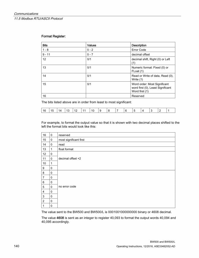
Communications 11.5 Modbus RTU/ASCII Protocol
BW500 and BW500/L 140 Operating Instructions, 12/2016, A5E33482052-AD
Format Register: Bits Values Description 1 - 8 0 - 2 Error Code 9 - 11 0 - 7 decimal offset 12 0/1 decimal shift, Right (0) or Left
(1) 13 0/1 Numeric format: Fixed (0) or
FLoat (1) 14 0/1 Read or Write of data, Read (0),
Write (1) 15 0/1 Word order: Most Significant
word first (0), Least Significant Word first (1)
16 Reserved
The bits listed above are in order from least to most significant: 16 15 14 13 12 11 10 9 8 7 6 5 4 3 2 1
For example, to format the output value so that it is shown with two decimal places shifted to the left the format bits would look like this: 16 0 reserved 15 0 most significant first 14 0 read 13 1 float format 12 0
decimal offset +2 11 0 10 1 9 0 8 0
no error code
7 0 6 0 5 0 4 0 3 0 2 0 1 0
The value sent to the BW500 and BW500/L is 0001001000000000 binary or 4608 decimal.
The value 4608 is sent as an integer to register 40,093 to format the output words 40,094 and 40,095 accordingly.
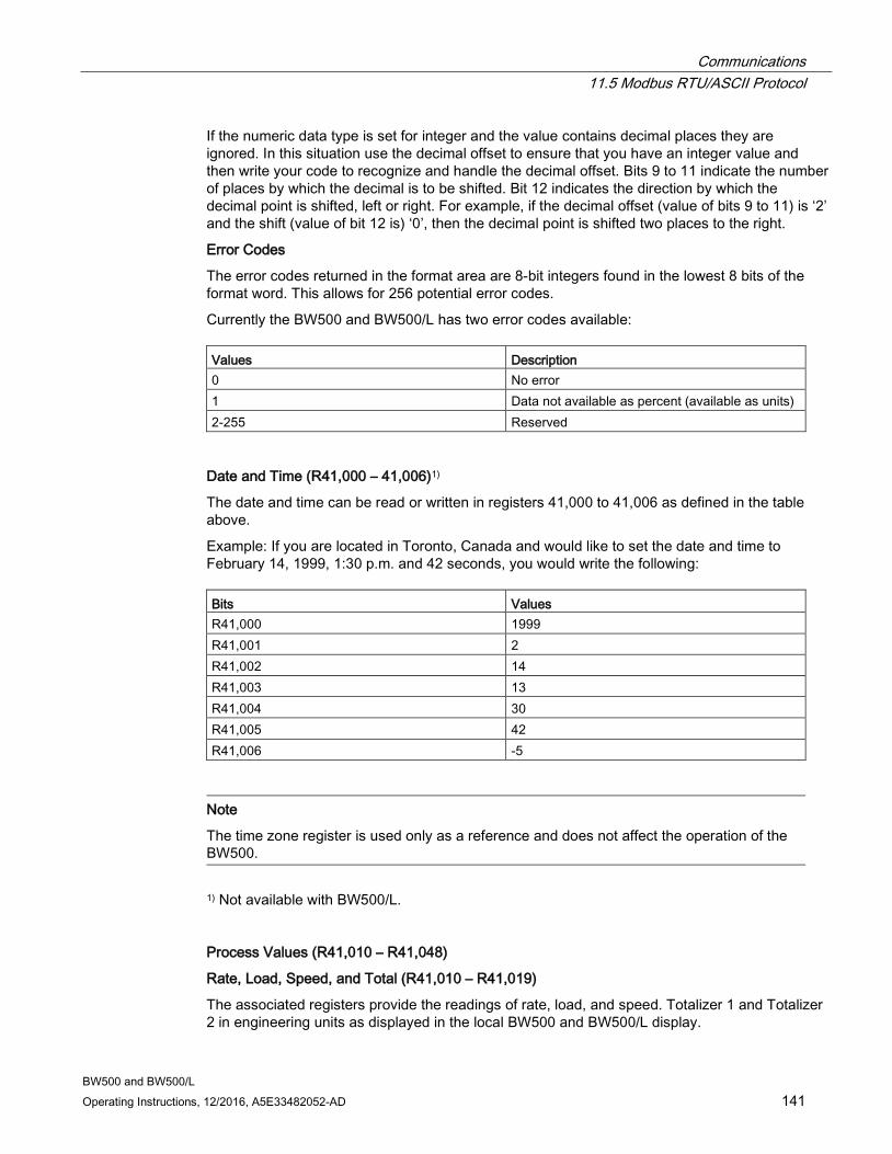
Communications 11.5 Modbus RTU/ASCII Protocol
BW500 and BW500/L Operating Instructions, 12/2016, A5E33482052-AD 141
If the numeric data type is set for integer and the value contains decimal places they are ignored. In this situation use the decimal offset to ensure that you have an integer value and then write your code to recognize and handle the decimal offset. Bits 9 to 11 indicate the number of places by which the decimal is to be shifted. Bit 12 indicates the direction by which the decimal point is shifted, left or right. For example, if the decimal offset (value of bits 9 to 11) is ‘2’ and the shift (value of bit 12 is) ‘0’, then the decimal point is shifted two places to the right.
Error Codes
The error codes returned in the format area are 8-bit integers found in the lowest 8 bits of the format word. This allows for 256 potential error codes.
Currently the BW500 and BW500/L has two error codes available: Values Description 0 No error 1 Data not available as percent (available as units) 2-255 Reserved
Date and Time (R41,000 – 41,006)1)
The date and time can be read or written in registers 41,000 to 41,006 as defined in the table above.
Example: If you are located in Toronto, Canada and would like to set the date and time to February 14, 1999, 1:30 p.m. and 42 seconds, you would write the following: Bits Values R41,000 1999 R41,001 2 R41,002 14 R41,003 13 R41,004 30 R41,005 42 R41,006 -5
Note
The time zone register is used only as a reference and does not affect the operation of the BW500.
1) Not available with BW500/L.
Process Values (R41,010 – R41,048)
Rate, Load, Speed, and Total (R41,010 – R41,019)
The associated registers provide the readings of rate, load, and speed. Totalizer 1 and Totalizer 2 in engineering units as displayed in the local BW500 and BW500/L display.
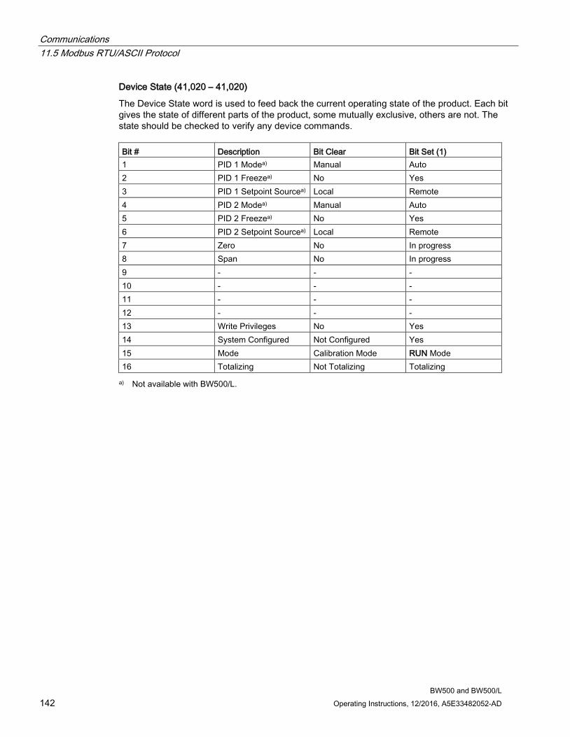
Communications 11.5 Modbus RTU/ASCII Protocol
BW500 and BW500/L 142 Operating Instructions, 12/2016, A5E33482052-AD
Device State (41,020 – 41,020)
The Device State word is used to feed back the current operating state of the product. Each bit gives the state of different parts of the product, some mutually exclusive, others are not. The state should be checked to verify any device commands. Bit # Description Bit Clear Bit Set (1) 1 PID 1 Modea) Manual Auto 2 PID 1 Freezea) No Yes 3 PID 1 Setpoint Sourcea) Local Remote 4 PID 2 Modea) Manual Auto 5 PID 2 Freezea) No Yes 6 PID 2 Setpoint Sourcea) Local Remote 7 Zero No In progress 8 Span No In progress 9 - - - 10 - - - 11 - - - 12 - - - 13 Write Privileges No Yes 14 System Configured Not Configured Yes 15 Mode Calibration Mode RUN Mode 16 Totalizing Not Totalizing Totalizing a) Not available with BW500/L.
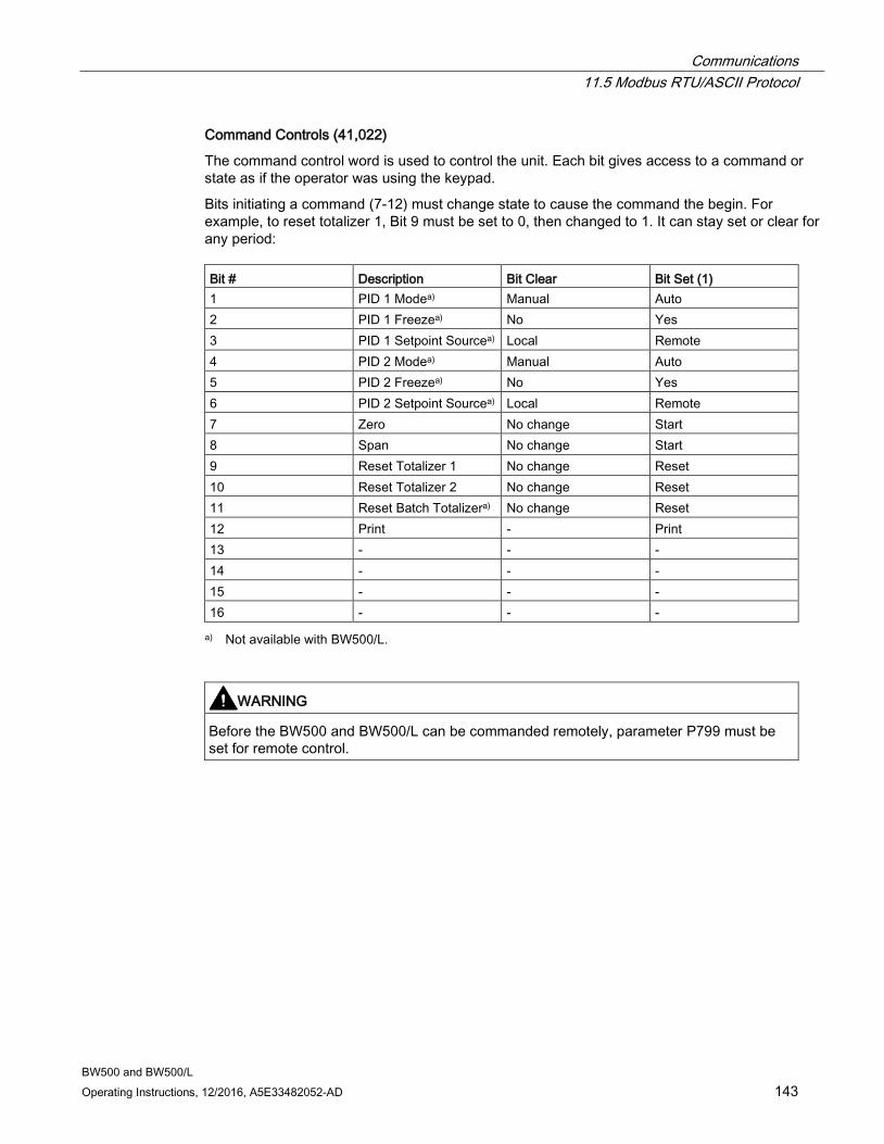
Communications 11.5 Modbus RTU/ASCII Protocol
BW500 and BW500/L Operating Instructions, 12/2016, A5E33482052-AD 143
Command Controls (41,022)
The command control word is used to control the unit. Each bit gives access to a command or state as if the operator was using the keypad.
Bits initiating a command (7-12) must change state to cause the command the begin. For example, to reset totalizer 1, Bit 9 must be set to 0, then changed to 1. It can stay set or clear for any period: Bit # Description Bit Clear Bit Set (1) 1 PID 1 Modea) Manual Auto 2 PID 1 Freezea) No Yes 3 PID 1 Setpoint Sourcea) Local Remote 4 PID 2 Modea) Manual Auto 5 PID 2 Freezea) No Yes 6 PID 2 Setpoint Sourcea) Local Remote 7 Zero No change Start 8 Span No change Start 9 Reset Totalizer 1 No change Reset 10 Reset Totalizer 2 No change Reset 11 Reset Batch Totalizera) No change Reset 12 Print - Print 13 - - - 14 - - - 15 - - - 16 - - - a) Not available with BW500/L.
WARNING
Before the BW500 and BW500/L can be commanded remotely, parameter P799 must be set for remote control.

Communications 11.5 Modbus RTU/ASCII Protocol
BW500 and BW500/L 144 Operating Instructions, 12/2016, A5E33482052-AD
Read/Write (R41,025 – R41,026) Total Decimal Places
Sets the number of decimal places (0-3) being read for Total 1, (words 41,016 and 41,017) and Total 2, (words 41,018 and 41,019).
With 3 decimal places, the largest value that can be read is 2,147,483.648.
With 2 decimal places, the largest value that can be read is 21,474,836.48.
With 1 or 0 decimal places, the largest value that can be read is 100,000,000.
Although the word registers are limited to reading a maximum value as indicated above for the defined number of decimal places, the overflow bits of Instrument_Status2 (Word 31) will only reflect an overflow condition (Bits 1 and 2 set to 1) when the decimal place is set to 2 or 3.
When set to 2 or 3, the word registers will stop accumulating at the indicated values however, the LUI will continue to totalize to a value of 100,000,000. Should this condition exist, prior to resetting the totalizer registers, be sure to observe and record the totalized value as displayed on the LUI. Not doing this could cause a reporting discrepancy in expected material totals within the process.
Once the internal totalizer registers realize a value of 100,000,000, the internal registers will perform a rollover, causing the display of the LUI to start from a value of 0. This will also cause the Instrument_Status2 word bits to reset to 0.
Example: R41,025
Bits 0 and 1 are used to indicate the number of decimal places being read in Total 1: words 7 and 8.
Bit 15 is used to indicate if the decimal place is too large to read the total value correctly.
If three decimal places are being read in Total 1: Bits 15 14 13 12 11 10 9 8 7 6 5 4 3 2 1 0 0 0 1 0 0 1 0 0 0 0 0 0 0 0 1 1
If three decimal places are being read in Total 1, and the value is too large to be read with three decimal places: Bits 15 14 13 12 11 10 9 8 7 6 5 4 3 2 1 0 1 0 1 0 0 1 0 0 0 0 0 0 0 0 1 1
I/O (R41,070 – 41,116)
The BW500 provides I/O in the form of:
● discrete inputs
● relay outputs
● mA inputs1)
● mA outputs1) 1) The standard BW500 provides only one mA output (0/4 – 20 mA). The inclusion of an optional mA I/O card provides two mA inputs (0/4 – 20 mA) and two additional mA outputs. The optional mA I/O card is not available with BW500/L
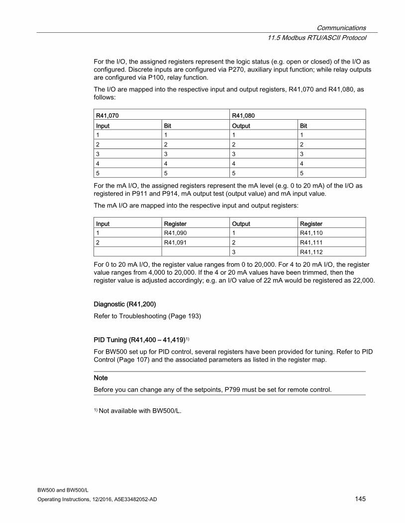
Communications 11.5 Modbus RTU/ASCII Protocol
BW500 and BW500/L Operating Instructions, 12/2016, A5E33482052-AD 145
For the I/O, the assigned registers represent the logic status (e.g. open or closed) of the I/O as configured. Discrete inputs are configured via P270, auxiliary input function; while relay outputs are configured via P100, relay function.
The I/O are mapped into the respective input and output registers, R41,070 and R41,080, as follows: R41,070 R41,080 Input Bit Output Bit 1 1 1 1 2 2 2 2 3 3 3 3 4 4 4 4 5 5 5 5
For the mA I/O, the assigned registers represent the mA level (e.g. 0 to 20 mA) of the I/O as registered in P911 and P914, mA output test (output value) and mA input value.
The mA I/O are mapped into the respective input and output registers: Input Register Output Register 1 R41,090 1 R41,110 2 R41,091 2 R41,111 3 R41,112
For 0 to 20 mA I/O, the register value ranges from 0 to 20,000. For 4 to 20 mA I/O, the register value ranges from 4,000 to 20,000. If the 4 or 20 mA values have been trimmed, then the register value is adjusted accordingly; e.g. an I/O value of 22 mA would be registered as 22,000.
Diagnostic (R41,200)
Refer to Troubleshooting (Page 193)
PID Tuning (R41,400 – 41,419)1)
For BW500 set up for PID control, several registers have been provided for tuning. Refer to PID Control (Page 107) and the associated parameters as listed in the register map.
Note
Before you can change any of the setpoints, P799 must be set for remote control.
1) Not available with BW500/L.
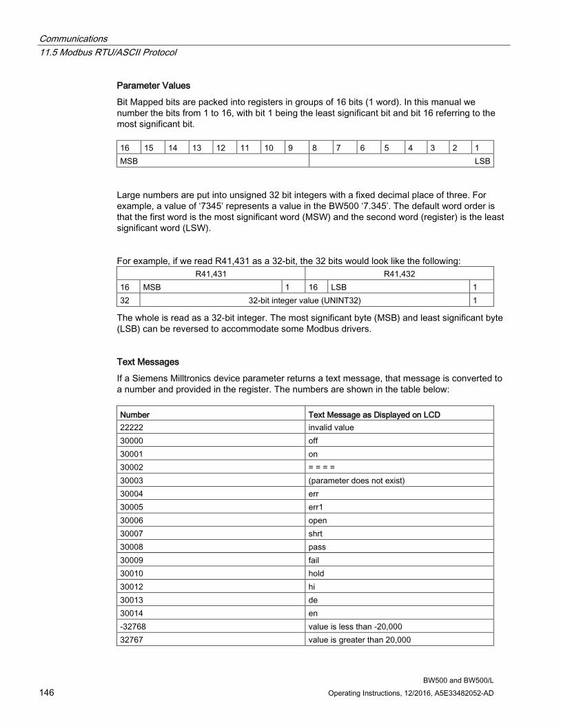
Communications 11.5 Modbus RTU/ASCII Protocol
BW500 and BW500/L 146 Operating Instructions, 12/2016, A5E33482052-AD
Parameter Values
Bit Mapped bits are packed into registers in groups of 16 bits (1 word). In this manual we number the bits from 1 to 16, with bit 1 being the least significant bit and bit 16 referring to the most significant bit. 16 15 14 13 12 11 10 9 8 7 6 5 4 3 2 1 MSB LSB
Large numbers are put into unsigned 32 bit integers with a fixed decimal place of three. For example, a value of ‘7345’ represents a value in the BW500 ‘7.345’. The default word order is that the first word is the most significant word (MSW) and the second word (register) is the least significant word (LSW).
For example, if we read R41,431 as a 32-bit, the 32 bits would look like the following: R41,431 R41,432
16 MSB 1 16 LSB 1 32 32-bit integer value (UNINT32) 1
The whole is read as a 32-bit integer. The most significant byte (MSB) and least significant byte (LSB) can be reversed to accommodate some Modbus drivers.
Text Messages
If a Siemens Milltronics device parameter returns a text message, that message is converted to a number and provided in the register. The numbers are shown in the table below: Number Text Message as Displayed on LCD 22222 invalid value 30000 off 30001 on 30002 = = = = 30003 (parameter does not exist) 30004 err 30005 err1 30006 open 30007 shrt 30008 pass 30009 fail 30010 hold 30012 hi 30013 de 30014 en -32768 value is less than -20,000 32767 value is greater than 20,000
Communications 11.6 Modems
BW500 and BW500/L Operating Instructions, 12/2016, A5E33482052-AD 147
11.6 Modems The BW500 and BW500/L has been successfully connected to several different modems. In general, the Modbus protocol is a very modem friendly protocol. This section gives some general guidelines on modems and their connection. For detailed information, see the modem documentation.
Picking Modems There are several different types of modems; dial-up, leased line, radio-link, fiber-optic, to name the most common.
Dial-up
uses a standard analog phone line and dials the number of the receiving modem.
Lease line
come in either 2 or 4 wire types and use special phone lines that are ‘leased’ from your phone company (or you) and do not require any dialing.
Radio-link
come in many different types, but all use radio frequencies for transmitting the information.
Fiber-optic
uses a fiber-optic line to connect the two modems.
Each type of modem and each model have various characteristics. Before purchasing the modem contact the modem manufacturer and ask if they have had experience using the modems with Modbus protocol with no flow control. If they have, ask them what settings were required.
Setting up the Modems Modems can be configured using software, dip switches, jumpers, or a combination.
Dip switches are normally located at the back of the modem, jumpers are normally located on the motherboard and require that you remove the cover. Software normally requires you to use a standard terminal program and to connect to the RS-232 port on the modem and send special commands. The most popular command set is called the AT, or Hayse, command set.
Your modem manual should give details on how to configure it.
11.6.1 Example Setup For a typical dial-up modem, try the following setup as a first attempt:
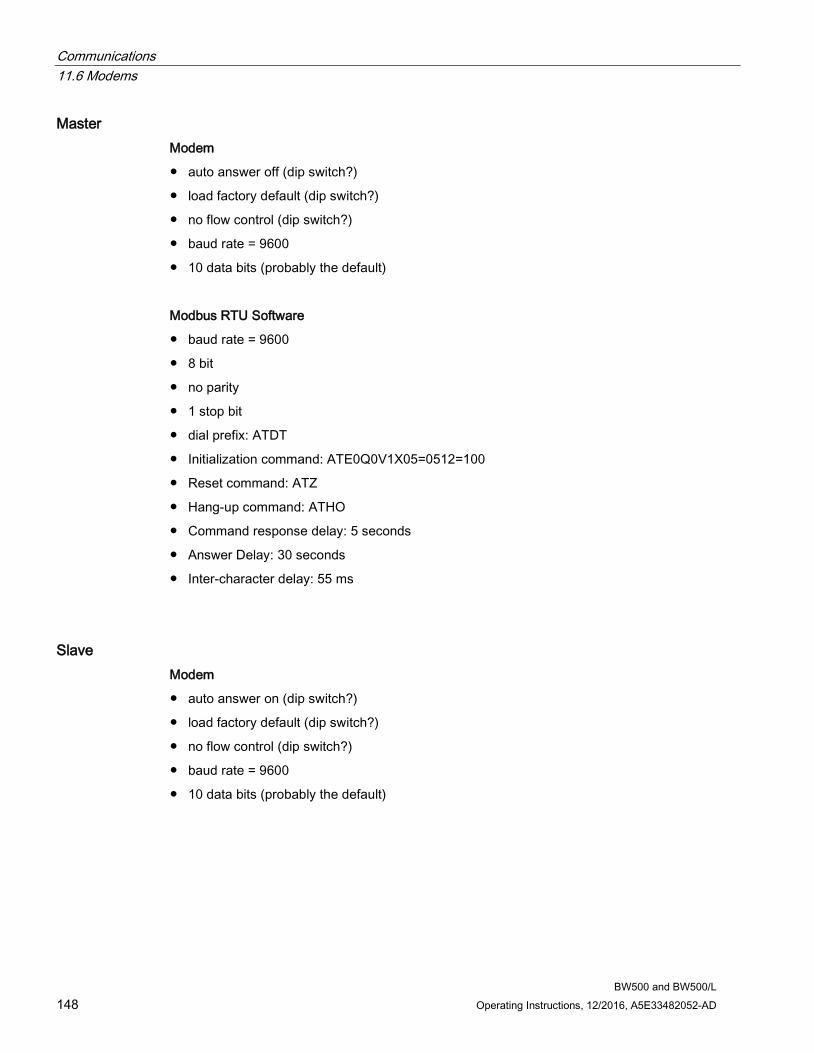
Communications 11.6 Modems
BW500 and BW500/L 148 Operating Instructions, 12/2016, A5E33482052-AD
Master Modem
● auto answer off (dip switch?)
● load factory default (dip switch?)
● no flow control (dip switch?)
● baud rate = 9600
● 10 data bits (probably the default)
Modbus RTU Software
● baud rate = 9600
● 8 bit
● no parity
● 1 stop bit
● dial prefix: ATDT
● Initialization command: ATE0Q0V1X05=0512=100
● Reset command: ATZ
● Hang-up command: ATHO
● Command response delay: 5 seconds
● Answer Delay: 30 seconds
● Inter-character delay: 55 ms
Slave Modem
● auto answer on (dip switch?)
● load factory default (dip switch?)
● no flow control (dip switch?)
● baud rate = 9600
● 10 data bits (probably the default)
Communications 11.7 Error Handling
BW500 and BW500/L Operating Instructions, 12/2016, A5E33482052-AD 149
BW500 and BW500/L
● set P770, port 1, to the value 3 (Modbus RTU)
● set P771, port 1, to the value 1 (Network ID 1)
● set P772, port 1, to the value 3 (Baud rate of 9600)
● set P773, port 1, to the value 0 (No Parity)
● set P774, port 1, to the value 8 (8 Data Bits)
● set P775, port 1, to the value 1 (1 Stop Bit)
● set P778, port 1, to the value 1 (Communications through Modem)
● set P779, port 1, to the value 300 (Modem Inactivity of 300 seconds)
Note
Parameters are defined the in the Installation section
11.7 Error Handling Modbus Responses
When polled by a Modbus Master, a slave device will do one of the following:
1. Not reply means something went wrong with the transmission of the message
2. Echo back the command with the correct response is the normal response, (see the Modbus specifications for more details)
3. Return an Exception Code reflects an error in the message
Communications 11.7 Error Handling
BW500 and BW500/L 150 Operating Instructions, 12/2016, A5E33482052-AD
BW500 and BW500/L uses the following exception codes: Code Name Meaning 01 Illegal Function The function code received in
the query is not an allowable action for the slave.
02 Illegal Data Address The data address received in the query is not an allowable address for the slave.
03 Illegal Data Value A value contained in the query data filed is not an allowable value of the slave.
04 Slave Device Failure An unrecoverable error occurred while the slave was attempting to perform the requested action.
05 Acknowledge The slave has accepted a re-quest and is processing it, but a long duration of time is required.
06 Slave Device Busy The slave is processing a long-duration program command.
08 Memory Parity Error The slave attempted to read extended memory, but detected a parity error in the memory. Service may be required on the slave.
Error Handling
Errors can be divided up into two general sources:
● an error in transmission
● user tries to do something that is not a valid action
In the first case, the BW500 and BW500/L will not respond and let the master wait for a ‘response time out’ error, which will cause the master to re-send the message.
In the second case, it depends on what the user tries to do. Listed below are various actions and what the expected outcome is. In general, BW500 and BW500/L will not give an error to the user request. ● If the user reads an invalid parameter, the user will get a number back. ● If the user writes an invalid parameter (a non-existing parameter or a read only parameter),
the value will be ignored and no error response will be made. However, the current value will not reflect the desired new value.
● If the user writes a read only register, then the value will be ignored and no error response will be made. However, the current value will not reflect the desired new value.
● If the user attempts to write one or more registers that are out of range, an exception response code 2 will be generated.
● If using an unsupported function code, undocumented results may occur. The user is encouraged not to do this.

Communications 11.7 Error Handling
BW500 and BW500/L Operating Instructions, 12/2016, A5E33482052-AD 151

BW500 and BW500/L Operating Instructions, 12/2016, A5E33482052-AD 153
Parameters 12
f indicates factory set value
P000 Security Lock Locks out the program editor so that parameter values for P001 through P999 cannot be changed. This however, does not prevent the access to the parameters for viewing.
Programming is locked out if the value of P000 is other than 1954.
Entry:
1954 = unlockedf
12.1 Start Up (P001 to P017) This is the minimum parameter programming required before attempting a calibration and successful entry into the RUN mode.
12.1.1 P001 Language Selects the language for communication with the BW500 and BW500/L
Entry: 1 = Englishf 5 = Italian 2 = French 6 = Portuguese 3 = German 7 = Russian 4 = Spanish
12.1.2 P002 Test Reference Selection Selects the type of test reference used to represent a material load: weight, chain, or electronic. weight: the weight that is supplied specific to the scale chain: optional, sized specific to scale and conveyor electronic: calibration based on automatic calculation of the
mV span from the load cells
Entry:
1 = weightf 2 = chain
3 = ECal
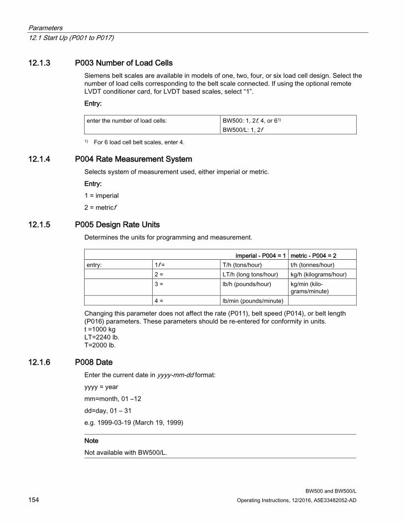
Parameters 12.1 Start Up (P001 to P017)
BW500 and BW500/L 154 Operating Instructions, 12/2016, A5E33482052-AD
12.1.3 P003 Number of Load Cells Siemens belt scales are available in models of one, two, four, or six load cell design. Select the number of load cells corresponding to the belt scale connected. If using the optional remote LVDT conditioner card, for LVDT based scales, select “1”.
Entry: enter the number of load cells: BW500: 1, 2f, 4, or 61)
BW500/L: 1, 2f 1) For 6 load cell belt scales, enter 4.
12.1.4 P004 Rate Measurement System Selects system of measurement used, either imperial or metric.
Entry:
1 = imperial
2 = metricf
12.1.5 P005 Design Rate Units Determines the units for programming and measurement.
imperial - P004 = 1 metric - P004 = 2 entry: 1f = T/h (tons/hour) t/h (tonnes/hour) 2 = LT/h (long tons/hour) kg/h (kilograms/hour) 3 = lb/h (pounds/hour) kg/min (kilo-
grams/minute) 4 = lb/min (pounds/minute)
Changing this parameter does not affect the rate (P011), belt speed (P014), or belt length (P016) parameters. These parameters should be re-entered for conformity in units. t =1000 kg LT=2240 lb. T=2000 lb.
12.1.6 P008 Date Enter the current date in yyyy-mm-dd format:
yyyy = year
mm=month, 01 –12
dd=day, 01 – 31
e.g. 1999-03-19 (March 19, 1999)
Note
Not available with BW500/L.
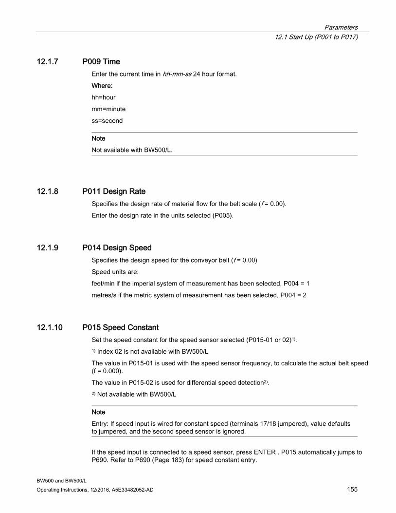
Parameters 12.1 Start Up (P001 to P017)
BW500 and BW500/L Operating Instructions, 12/2016, A5E33482052-AD 155
12.1.7 P009 Time Enter the current time in hh-mm-ss 24 hour format.
Where:
hh=hour
mm=minute
ss=second
Note
Not available with BW500/L.
12.1.8 P011 Design Rate Specifies the design rate of material flow for the belt scale (f = 0.00).
Enter the design rate in the units selected (P005).
12.1.9 P014 Design Speed Specifies the design speed for the conveyor belt (f = 0.00)
Speed units are:
feet/min if the imperial system of measurement has been selected, P004 = 1
metres/s if the metric system of measurement has been selected, P004 = 2
12.1.10 P015 Speed Constant Set the speed constant for the speed sensor selected (P015-01 or 02)1). 1) Index 02 is not available with BW500/L
The value in P015-01 is used with the speed sensor frequency, to calculate the actual belt speed (f = 0.000).
The value in P015-02 is used for differential speed detection2). 2) Not available with BW500/L
Note
Entry: If speed input is wired for constant speed (terminals 17/18 jumpered), value defaults to jumpered, and the second speed sensor is ignored.
If the speed input is connected to a speed sensor, press ENTER . P015 automatically jumps to P690. Refer to P690 (Page 183) for speed constant entry.

Parameters 12.1 Start Up (P001 to P017)
BW500 and BW500/L 156 Operating Instructions, 12/2016, A5E33482052-AD
12.1.11 P016 Belt Length The length of the conveyor belt (one belt revolution) (f = 0.000)
Length units are:
feet: if the imperial system of measurement has been selected, P004 = 1
metres: if the metric system of measurement has been selected, P004 = 2
Enter the belt length.
12.1.12 P017 Test Load The load to be referenced when performing a span (f = 0.00).
Load units are:
lb/ft: if the imperial system of measurement has been selected, P004 = 1
kg/m: if the metric system of measurement has been selected, P004 = 2
The display indicates the test reference as selected by P002: ‘weight’, ‘chain’, or ‘ECal’ and the multispan number MS, 1-81). 1) Multispan function is not available with BW500/L.
Enter the test load value. In the case of weight, pressing enter at P017 invokes P680 for data entry.
In the case of ECal, pressing enter at P017 invokes P693 for data entry. ECal sets the value for P017 at 100% of design load (P952).
In the case of chain, pressing enter at P017 allows direct entry of the load value stamped on the chain’s name plate.
If P002 is set to 'weight' the test load parameter presents two options:
1. enter the load in weight/unit length Set P680 Test Load: Weight (Options) to ’1-Enter Value’, and then enter the desired value for P017. or
2. the mass and the weigh length. Set P680 Test Load: Weight (Options) (Page 183) to ’2-Enter Data’ and then enter the ’Total Mass of Test Weights’ in P681, and the ’Average Idler Space’ in P682.
Example:
3 standard MSI test weights, 1.2 meter idler spacing
Test Load: 24.6 kg (3x8.2 kg)/(1.2 m) =20.5 kg/m

Parameters 12.1 Start Up (P001 to P017)
BW500 and BW500/L Operating Instructions, 12/2016, A5E33482052-AD 157
12.1.13 P018 Speed Adjust This parameter allows adjustment to the speed constant for both speed sensors (P015-01 or P015-02)2). Initially, this parameter displays the dynamic speed of the belt. If thedisplayed speed is not equal to the actual speed, enter the actual belt speed (f = 0.00).
For speed sensor applications, the value of P015 is automatically adjusted.
For constant speed (terminals 17/18 jumpered) the value of P014 is automatically adjusted. 2) Not available with BW500/L
12.1.14 P019 Manual Span Adjust Provides a means for adjustment to the span calibration (f = 0)
The adjustment value is determined by performing material tests and is subsequently entered either as a calculation of % change into P598, or as the weight of the material test.
Entry:
1 = % change
2 = material test
Refer to Recalibration (Page 67).
12.1.15 P022 Minimum Speed Frequency Sets the minimum frequency that the speed sensor can reliably read. Signals at low frequencies are erratic, adversely affecting the performance of the weighing system.
Entry:
1 = 1 Hz (at 1 Hz, it takes 1 s before defaulting to 0 speed)
2 = 2 Hzf (at 2 Hz, it takes 0.5 s before defaulting to 0 speed)
12.1.16 P080 Display Damping P080-01 Rate
P080-02 Load
P080-03 Speed
Sets the speed of response to which the displayed readings (rate, load, and speed), and outputs (alarm and mA1)) react to change.Refer to Operation (Page 97).
Note
Effect of damping (P080-01) on mA output can be overridden by mA output damping (P220).
The higher the damping value, the slower the response.
Enter damping value, range 0.000f – 999 1) Damping is not applicable to the mA output if programmed for PID function (P201 = 4).
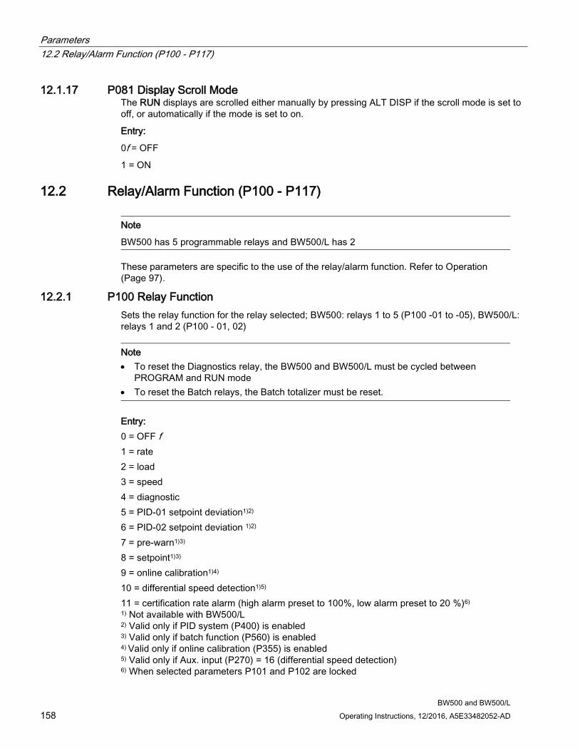
Parameters 12.2 Relay/Alarm Function (P100 - P117)
BW500 and BW500/L 158 Operating Instructions, 12/2016, A5E33482052-AD
12.1.17 P081 Display Scroll Mode The RUN displays are scrolled either manually by pressing ALT DISP if the scroll mode is set to off, or automatically if the mode is set to on.
Entry:
0f = OFF
1 = ON
12.2 Relay/Alarm Function (P100 - P117)
Note
BW500 has 5 programmable relays and BW500/L has 2
These parameters are specific to the use of the relay/alarm function. Refer to Operation (Page 97).
12.2.1 P100 Relay Function Sets the relay function for the relay selected; BW500: relays 1 to 5 (P100 -01 to -05), BW500/L: relays 1 and 2 (P100 - 01, 02)
Note • To reset the Diagnostics relay, the BW500 and BW500/L must be cycled between
PROGRAM and RUN mode • To reset the Batch relays, the Batch totalizer must be reset.
Entry: 0 = OFF f 1 = rate 2 = load 3 = speed 4 = diagnostic 5 = PID-01 setpoint deviation1)2) 6 = PID-02 setpoint deviation 1)2) 7 = pre-warn1)3) 8 = setpoint1)3) 9 = online calibration1)4) 10 = differential speed detection1)5) 11 = certification rate alarm (high alarm preset to 100%, low alarm preset to 20 %)6) 1) Not available with BW500/L 2) Valid only if PID system (P400) is enabled 3) Valid only if batch function (P560) is enabled 4) Valid only if online calibration (P355) is enabled 5) Valid only if Aux. input (P270) = 16 (differential speed detection) 6) When selected parameters P101 and P102 are locked
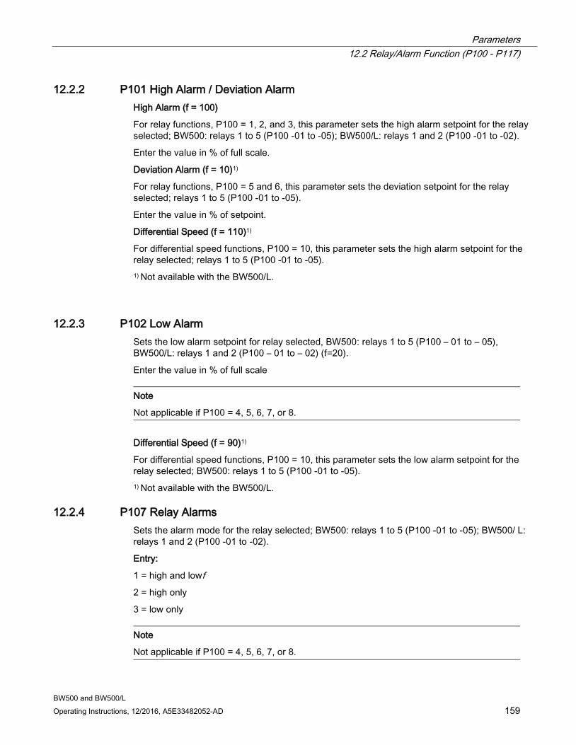
Parameters 12.2 Relay/Alarm Function (P100 - P117)
BW500 and BW500/L Operating Instructions, 12/2016, A5E33482052-AD 159
12.2.2 P101 High Alarm / Deviation Alarm High Alarm (f = 100)
For relay functions, P100 = 1, 2, and 3, this parameter sets the high alarm setpoint for the relay selected; BW500: relays 1 to 5 (P100 -01 to -05); BW500/L: relays 1 and 2 (P100 -01 to -02).
Enter the value in % of full scale.
Deviation Alarm (f = 10)1)
For relay functions, P100 = 5 and 6, this parameter sets the deviation setpoint for the relay selected; relays 1 to 5 (P100 -01 to -05).
Enter the value in % of setpoint.
Differential Speed (f = 110)1)
For differential speed functions, P100 = 10, this parameter sets the high alarm setpoint for the relay selected; relays 1 to 5 (P100 -01 to -05). 1) Not available with the BW500/L.
12.2.3 P102 Low Alarm Sets the low alarm setpoint for relay selected, BW500: relays 1 to 5 (P100 – 01 to – 05), BW500/L: relays 1 and 2 (P100 – 01 to – 02) (f=20).
Enter the value in % of full scale
Note
Not applicable if P100 = 4, 5, 6, 7, or 8.
Differential Speed (f = 90)1)
For differential speed functions, P100 = 10, this parameter sets the low alarm setpoint for the relay selected; BW500: relays 1 to 5 (P100 -01 to -05). 1) Not available with the BW500/L.
12.2.4 P107 Relay Alarms Sets the alarm mode for the relay selected; BW500: relays 1 to 5 (P100 -01 to -05); BW500/ L: relays 1 and 2 (P100 -01 to -02).
Entry:
1 = high and lowf 2 = high only
3 = low only
Note
Not applicable if P100 = 4, 5, 6, 7, or 8.
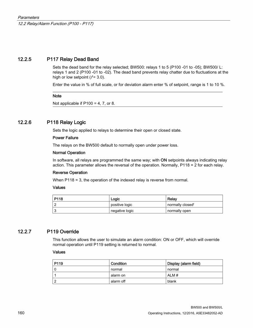
Parameters 12.2 Relay/Alarm Function (P100 - P117)
BW500 and BW500/L 160 Operating Instructions, 12/2016, A5E33482052-AD
12.2.5 P117 Relay Dead Band Sets the dead band for the relay selected; BW500: relays 1 to 5 (P100 -01 to -05); BW500/ L: relays 1 and 2 (P100 -01 to -02). The dead band prevents relay chatter due to fluctuations at the high or low setpoint (f = 3.0).
Enter the value in % of full scale, or for deviation alarm enter % of setpoint, range is 1 to 10 %.
Note
Not applicable if P100 = 4, 7, or 8.
12.2.6 P118 Relay Logic
Sets the logic applied to relays to determine their open or closed state.
Power Failure
The relays on the BW500 default to normally open under power loss.
Normal Operation
In software, all relays are programmed the same way; with ON setpoints always indicating relay action. This parameter allows the reversal of the operation. Normally, P118 = 2 for each relay.
Reverse Operation
When P118 = 3, the operation of the indexed relay is reverse from normal.
Values P118 Logic Relay 2 positive logic normally closedf 3 negative logic normally open
12.2.7 P119 Override This function allows the user to simulate an alarm condition: ON or OFF, which will override normal operation until P119 setting is returned to normal.
Values P119 Condition Display (alarm field) 0 normal normal 1 alarm on ALM # 2 alarm off blank

Parameters 12.3 mA I/O Parameters (P200 - P220)
BW500 and BW500/L Operating Instructions, 12/2016, A5E33482052-AD 161
12.3 mA I/O Parameters (P200 - P220) These parameters are specific to the use of the mA output. Refer to mA Output (Page 101)for details.
● mA output 1 is physically located at terminals 21/22 on the main board
● mA outputs 2 and 3, and inputs 1 and 2 are physically located on the optional mA I/O board which is mounted onto the main board.1)
In the case of assigning mA input and output functions to PID control1), the following correlation exist: mA input mA output PID control 1 1 2 PID control 2 2 3
1) Not available with the BW500/L.
12.3.1 P200 mA Output Range Sets the mA range for the output selected, outputs 1 to 3 (P200 - 01 to - 03)2). Entry: 1 = 0 - 20 mA 2 = 4 - 20 mAf 2) BW500/L has one output, parameters will not present multiple indexes.
12.3.2 P201 mA Output Function Assigns the mA output function for the output selected, outputs 1 to 3 (P201 - 01 to - 03)2)
Entry: 1 = ratef 2 = load 3 = speed 4 = PID control output3) 4) 2) BW500/L has one output, parameters will not present multiple indexes. 3) Not available with BW500/L. 4) Valid for outputs 2 and 3, only if PID system (P400) is enabled.
12.3.3 P204 mA Output Average Sets the averaging period, in seconds, for the rate output for output 1 only.
The instantaneous mA values are averaged for the set period, and then the average value is output during the next period while a new average is being calculated.
Entry: 0 = OFFf 1 – 999 = averaging period
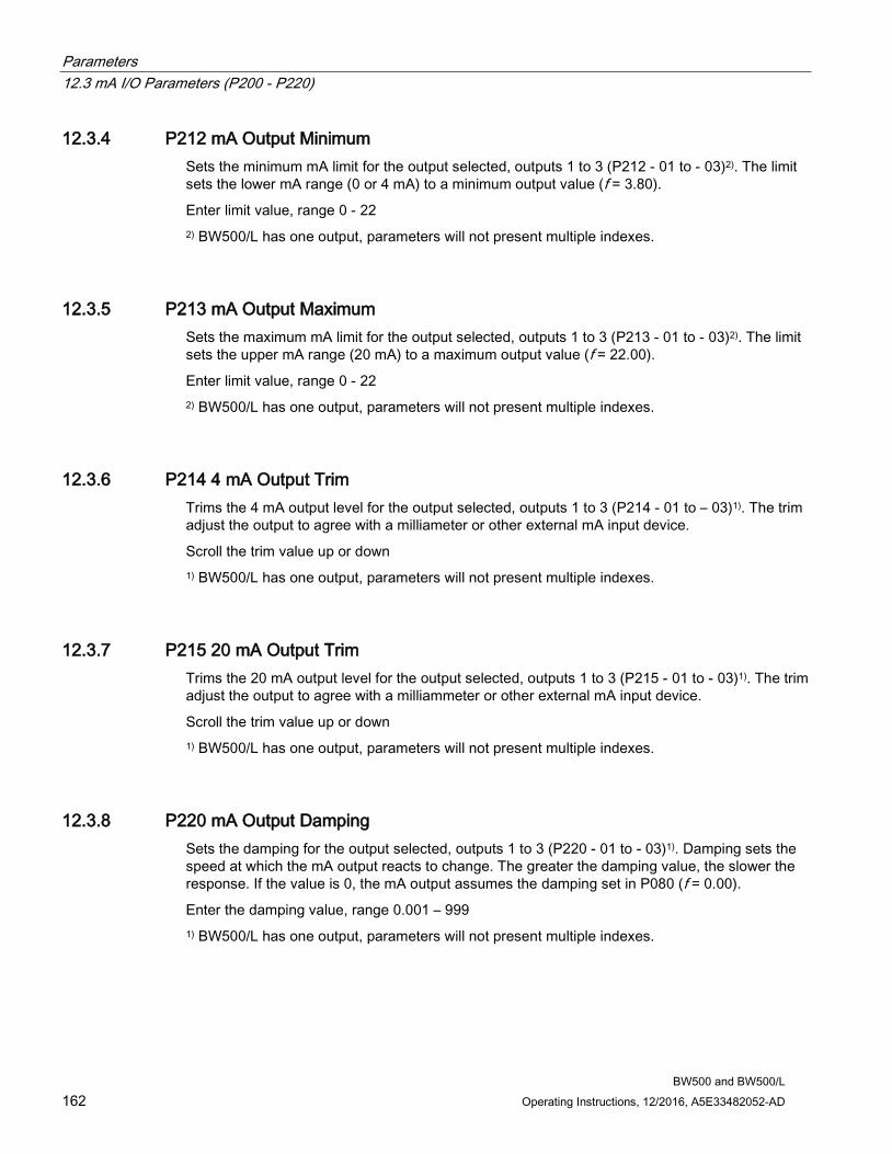
Parameters 12.3 mA I/O Parameters (P200 - P220)
BW500 and BW500/L 162 Operating Instructions, 12/2016, A5E33482052-AD
12.3.4 P212 mA Output Minimum Sets the minimum mA limit for the output selected, outputs 1 to 3 (P212 - 01 to - 03)2). The limit sets the lower mA range (0 or 4 mA) to a minimum output value (f = 3.80).
Enter limit value, range 0 - 22 2) BW500/L has one output, parameters will not present multiple indexes.
12.3.5 P213 mA Output Maximum Sets the maximum mA limit for the output selected, outputs 1 to 3 (P213 - 01 to - 03)2). The limit sets the upper mA range (20 mA) to a maximum output value (f = 22.00).
Enter limit value, range 0 - 22 2) BW500/L has one output, parameters will not present multiple indexes.
12.3.6 P214 4 mA Output Trim Trims the 4 mA output level for the output selected, outputs 1 to 3 (P214 - 01 to – 03)1). The trim adjust the output to agree with a milliameter or other external mA input device.
Scroll the trim value up or down 1) BW500/L has one output, parameters will not present multiple indexes.
12.3.7 P215 20 mA Output Trim Trims the 20 mA output level for the output selected, outputs 1 to 3 (P215 - 01 to - 03)1). The trim adjust the output to agree with a milliammeter or other external mA input device.
Scroll the trim value up or down 1) BW500/L has one output, parameters will not present multiple indexes.
12.3.8 P220 mA Output Damping Sets the damping for the output selected, outputs 1 to 3 (P220 - 01 to - 03)1). Damping sets the speed at which the mA output reacts to change. The greater the damping value, the slower the response. If the value is 0, the mA output assumes the damping set in P080 (f = 0.00).
Enter the damping value, range 0.001 – 999 1) BW500/L has one output, parameters will not present multiple indexes.
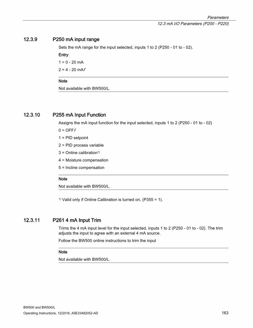
Parameters 12.3 mA I/O Parameters (P200 - P220)
BW500 and BW500/L Operating Instructions, 12/2016, A5E33482052-AD 163
12.3.9 P250 mA input range Sets the mA range for the input selected, inputs 1 to 2 (P250 - 01 to - 02).
Entry:
1 = 0 - 20 mA
2 = 4 - 20 mAf
Note
Not available with BW500/L.
12.3.10 P255 mA Input Function Assigns the mA input function for the input selected, inputs 1 to 2 (P250 - 01 to - 02)
0 = OFFf 1 = PID setpoint
2 = PID process variable
3 = Online calibration1)
4 = Moisture compensation
5 = Incline compensation
Note
Not available with BW500/L.
1) Valid only if Online Calibration is turned on, (P355 = 1).
12.3.11 P261 4 mA Input Trim Trims the 4 mA input level for the input selected, inputs 1 to 2 (P250 - 01 to - 02). The trim adjusts the input to agree with an external 4 mA source.
Follow the BW500 online instructions to trim the input
Note
Not available with BW500/L.

Parameters 12.3 mA I/O Parameters (P200 - P220)
BW500 and BW500/L 164 Operating Instructions, 12/2016, A5E33482052-AD
12.3.12 P262 20 mA Input Trim Trims the 20 mA input level for the input selected, inputs 1 to 2 (P250 - 01 to - 02). The trim adjusts the input to agree with an external 20 mA source.
Follow the BW500 online instructions to trim the input.
Note
Not available with BW500/L.
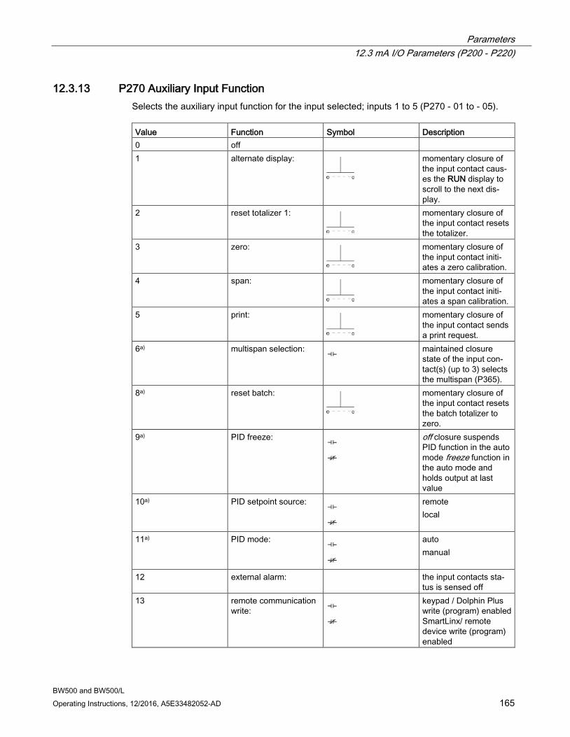
Parameters 12.3 mA I/O Parameters (P200 - P220)
BW500 and BW500/L Operating Instructions, 12/2016, A5E33482052-AD 165
12.3.13 P270 Auxiliary Input Function Selects the auxiliary input function for the input selected; inputs 1 to 5 (P270 - 01 to - 05). Value Function Symbol Description 0 off 1 alternate display:
momentary closure of the input contact caus-es the RUN display to scroll to the next dis-play.
2 reset totalizer 1:
momentary closure of the input contact resets the totalizer.
3 zero:
momentary closure of the input contact initi-ates a zero calibration.
4 span:
momentary closure of the input contact initi-ates a span calibration.
5 print:
momentary closure of the input contact sends a print request.
6a) multispan selection: maintained closure state of the input con-tact(s) (up to 3) selects the multispan (P365).
8a) reset batch:
momentary closure of the input contact resets the batch totalizer to zero.
9a) PID freeze:
off closure suspends PID function in the auto mode freeze function in the auto mode and holds output at last value
10a) PID setpoint source:
remote local
11a) PID mode:
auto manual
12 external alarm: the input contacts sta-tus is sensed off
13 remote communication write:
keypad / Dolphin Plus write (program) enabled SmartLinx/ remote device write (program) enabled
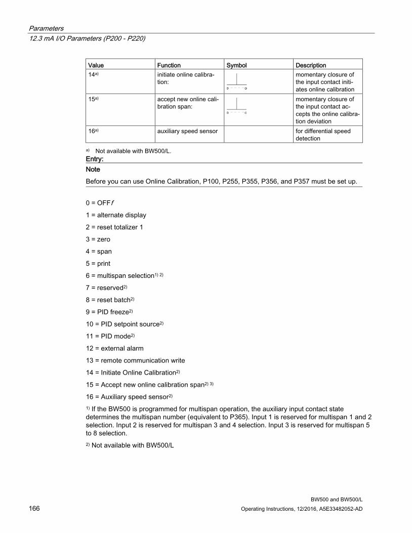
Parameters 12.3 mA I/O Parameters (P200 - P220)
BW500 and BW500/L 166 Operating Instructions, 12/2016, A5E33482052-AD
Value Function Symbol Description 14a) initiate online calibra-
tion:
momentary closure of the input contact initi-ates online calibration
15a) accept new online cali-bration span:
momentary closure of the input contact ac-cepts the online calibra-tion deviation
16a) auxiliary speed sensor for differential speed detection
a) Not available with BW500/L. Entry:
Note
Before you can use Online Calibration, P100, P255, P355, P356, and P357 must be set up.
0 = OFFf 1 = alternate display
2 = reset totalizer 1
3 = zero
4 = span
5 = print
6 = multispan selection1) 2)
7 = reserved2)
8 = reset batch2)
9 = PID freeze2)
10 = PID setpoint source2)
11 = PID mode2)
12 = external alarm
13 = remote communication write
14 = Initiate Online Calibration2)
15 = Accept new online calibration span2) 3)
16 = Auxiliary speed sensor2) 1) If the BW500 is programmed for multispan operation, the auxiliary input contact state determines the multispan number (equivalent to P365). Input 1 is reserved for multispan 1 and 2 selection. Input 2 is reserved for multispan 3 and 4 selection. Input 3 is reserved for multispan 5 to 8 selection. 2) Not available with BW500/L
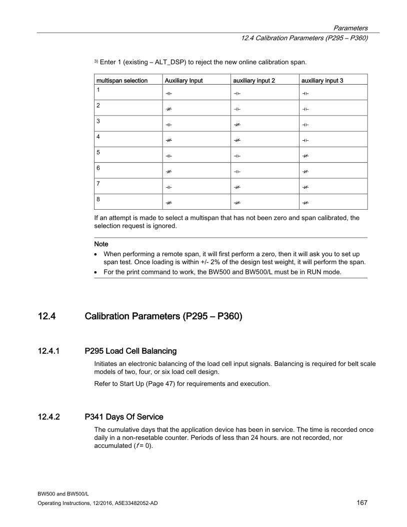
Parameters 12.4 Calibration Parameters (P295 – P360)
BW500 and BW500/L Operating Instructions, 12/2016, A5E33482052-AD 167
3) Enter 1 (existing – ALT_DSP) to reject the new online calibration span. multispan selection Auxiliary Input auxiliary input 2 auxiliary input 3 1
2
3
4
5
6
7
8
If an attempt is made to select a multispan that has not been zero and span calibrated, the selection request is ignored.
Note • When performing a remote span, it will first perform a zero, then it will ask you to set up
span test. Once loading is within +/- 2% of the design test weight, it will perform the span. • For the print command to work, the BW500 and BW500/L must be in RUN mode.
12.4 Calibration Parameters (P295 – P360)
12.4.1 P295 Load Cell Balancing Initiates an electronic balancing of the load cell input signals. Balancing is required for belt scale models of two, four, or six load cell design.
Refer to Start Up (Page 47) for requirements and execution.
12.4.2 P341 Days Of Service The cumulative days that the application device has been in service. The time is recorded once daily in a non-resetable counter. Periods of less than 24 hours. are not recorded, nor accumulated (f = 0).
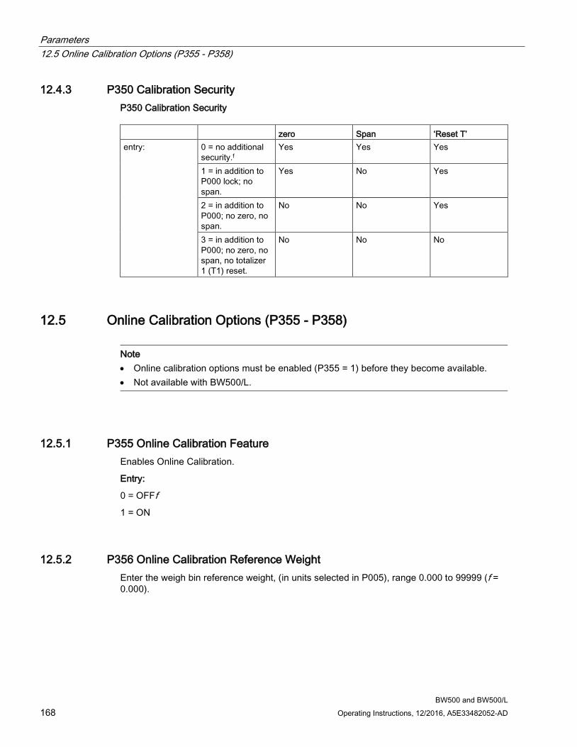
Parameters 12.5 Online Calibration Options (P355 - P358)
BW500 and BW500/L 168 Operating Instructions, 12/2016, A5E33482052-AD
12.4.3 P350 Calibration Security P350 Calibration Security zero Span ‘Reset T’ entry: 0 = no additional
security.f Yes Yes Yes
1 = in addition to P000 lock; no span.
Yes No Yes
2 = in addition to P000; no zero, no span.
No No Yes
3 = in addition to P000; no zero, no span, no totalizer 1 (T1) reset.
No No No
12.5 Online Calibration Options (P355 - P358)
Note • Online calibration options must be enabled (P355 = 1) before they become available. • Not available with BW500/L.
12.5.1 P355 Online Calibration Feature Enables Online Calibration.
Entry:
0 = OFFf 1 = ON
12.5.2 P356 Online Calibration Reference Weight Enter the weigh bin reference weight, (in units selected in P005), range 0.000 to 99999 (f = 0.000).

Parameters 12.5 Online Calibration Options (P355 - P358)
BW500 and BW500/L Operating Instructions, 12/2016, A5E33482052-AD 169
12.5.3 P357 Online Calibration Limits Use to enter the weigh bin limit settings.
P357.1 MAX LIMIT, range 0.0 to 100.0 (f = 0%)
P357.2 HIGH LIMIT, range 0.0 to 100.0 (f = 0%)
P357.3 LOW LIMIT, range 0.0 to 100.0 (f = 0%)
12.5.4 P358 Online Calibration Activation Initiates online calibration.
Entry:
0 = OFFf 1 = ON
12.5.5 P359 Factoring Factoring is used as a method of calculating the value of the test load (P017) to a new test reference; either: weight, or chain. The task is performed only for the weight or chain relevant for the multispan selected, if applicable.
Entry:
1 = weight (f = 1)
2 = chain
Refer to Recalibration (Page 67) for execution of the factoring procedure.
Note
Totalization is halted during the factoring procedure, and resumed only upon return to the RUN mode.
12.5.6 P360 Calibration Duration Sets the number of whole belt revolutions to be used during a zero or span calibration.
Enter number of belt revolutions, range 1 to 99. For belt scale applications 1 belt revolution or 2 minutes, whichever is longer; for weghfeeder applications 3 belt revolutions or 5 minutes, whichever is longer.

Parameters 12.5 Online Calibration Options (P355 - P358)
BW500 and BW500/L 170 Operating Instructions, 12/2016, A5E33482052-AD
12.5.7 P365 Multispan
Note
Not available with BW500/L.
Select the span reference to be applied for determination of rate and totalization.
Entry:
1 = multispan 1 (MS1), for product or condition Af
2 = multispan 2 (MS2), for product or condition B
3 = multispan 3 (MS3), for product or condition C
4 = multispan 4 (MS4), for product or condition D
5 = multispan 5 (MS5), for product or condition E
6 = multispan 6 (MS6), for product or condition F
7 = multispan 7 (MS7), for product or condition G
8 = multispan 8 (MS8), for product or condition H
Refer to Multispan and P270, Auxiliary Input Function (6).
12.5.8 P367 Direct Zero Entry Directly enters the zero reference count.
Direct entry is intended for use when replacing software or hardware and it is not convenient to perform an initial zero at that time (f = 0).
Refer to Recalibration (Page 67) for execution.
12.5.9 P368 Direct Span Entry Directly enters the span reference count for the span selected, 1 to 8 (P368-01 to -08).
Note
BW500/L has one span entry possible, no indices will be presented.
Direct entry is intended for use when replacing software or hardware and it is not convenient to perform an initial span at that time (f = 0).
Refer to Recalibration (Page 67) for execution.
Parameters 12.5 Online Calibration Options (P355 - P358)
BW500 and BW500/L Operating Instructions, 12/2016, A5E33482052-AD 171
12.5.10 P370 Zero Limit Deviation % Sets the zero calibration deviation limit (±) from the last initial zero. If the accumulated deviation of successive zero calibrations exceeds the limit, the zero calibration is aborted (f = 12.5).
Note
If the legal for trade certification switch has been set, the zero limit is ±2%.
Enter the maximum allowable % deviation, range is 1 to 12.5 %.
12.5.11 P371 Auto Zero Initiation Upper Limit This parameter sets maximum load on the belt as a percentage of design load at which the device will allow ’auto-zero’ to run, min. 1.0%, max. 10.0%, default 2.0%.
When the certification switch is set this parameter will assume the default value (2.0%).
Note
Material will not be totalized during auto zero calibrations.
12.5.12 P377 Initial Zero Resets the initial zero.
The initial zero is the reference zero to which all subsequent operator initiated zero calibrations are compared in determining whether they have deviated beyond the zero limit (P370) (f = 1).
Note
Refer to Initial Zero (Page 74) on for execution.
12.5.13 P388 Initial Span Resets the initial span for the span selected, multispan 1 to 8 (P388-01 to -08)1).
The initial span is the reference to which all subsequent span calibrations are compared in determining whether they have deviated beyond an accumulated ±12.5% of the initialspan (f = 1).
Note
Refer to Initial Span (Page 78) for execution.
1) BW500/L has one span entry possible, no indices will be presented.

Parameters 12.6 Linearization Parameters (P390 - P392)
BW500 and BW500/L 172 Operating Instructions, 12/2016, A5E33482052-AD
12.6 Linearization Parameters (P390 - P392) These parameters are used to compensate for non-linear response of the weighing system to the BW500 and BW500/L. Refer to Linearization for execution, and example on the use of these parameters.
Note
In the case of multispan operation, the linearizer is applied to all spans.
12.6.1 P390 Linearizer Enables or disables the linearization function.
Entry:
0 = OFFf 1 = ON
12.6.2 P391 Linearizer Load Points Enters the load values, in units of P017, for the point selected, points 1 to 5 (P391-01 to -05) (f = 0.00, 150 % max.)
12.6.3 P392 Linearizer Compensation % Enters the compensation value, in percent, for the point selected, point 1 to 5 (P392-01 to −05) (f = 0.00), range is -150 to 150 %.
12.6.4 P398-01 Moisture Content Factors out moisture component of load, rate and total for all multispans selected. The factored values are meant to report the dry mean values of the material being conveyed (f = 0.00)
Enter the moisture content in % weight or mA Input Value1). 1) BW500/L will allow manual entry of a moisture content.
12.6.5 P398-02 Moisture Content Allows moisture content P398-01 to be scaled to maximum value.
Enter the moisture content in % weight (maximum value 20 mA)
Note
Not available with BW500/L.
Parameters 12.7 Proportional Integral Derivative (PID) Control
BW500 and BW500/L Operating Instructions, 12/2016, A5E33482052-AD 173
12.6.6 P399 Incline Sensing Factors out the varying vertical force components applied to the belt scale for all multispans selected (f = 0.00). The value is presented in degree angle (0.0° = horizontal), with a range from -30 to 30 °.
P399 can also be used for a constant angle if a mA input is not configured. Otherwise, P399 will contain the current value corresponding to the mA input.1) 1) BW500/L does not have mA inputs, only a fixed incline compensation value can be entered.
12.7 Proportional Integral Derivative (PID) Control
Note • Changes to P401, P402, and P414 are not immediately effected while in auto mode.
Change should be made in the manual mode and are effected upon return to the auto mode.
• The PID function does not control during any of the calibration functions (e.g. zero, span, factor, material test).
• Not available with BW500/L.
12.7.1 P400 PID System Enables the selected PID system, systems 1 or 2 (P400 – 01 or – 02).
Entry:
0 = OFFf 1 = manual
2 = auto
12.7.2 P401 PID Update Time Sets the update time (P401 – 01 or -02) for the corresponding PID system (1 or 2).
Normally the controller is updated each time the process value is updated (every 300 ms). However in unstable or slow reacting systems the controller update can be programmed to update on a multiple of the process value update. A high value can introduce instability (f = 1).
Entry:
1 = 300 ms
2 = 600 ms
3 = 900 ms, etc.
Parameters 12.7 Proportional Integral Derivative (PID) Control
BW500 and BW500/L 174 Operating Instructions, 12/2016, A5E33482052-AD
12.7.3 P402 PID Process Value Source Determines the source of the process value (P402 – 01 or – 02) for the corresponding PID system (1 or 2)
The process value is the value that the controller is trying to match with the setpoint (f = 1)
Enter:
1 = ratef 2 = load
3 = mA input 1
4 = mA input 2
12.7.4 P405 Proportional Term Sets the proportional term (P405-01 or -02) for the corresponding PID system (1 or 2) (f = 0.400)
The proportional term is the proportional gain. A gain of 1 is equivalent to a proportional band of 100%.
The proportional band is the range of deviation from the setpoint that corresponds to the full range or the control output.
Enter the proportional term 0.000 to 2.000.
12.7.5 P406 Integral Term Sets the integral term (P406-01 or -02) for the corresponding PID system (1 or 2) (f = 0.200) Enter the integral term 0.000 to 2.000.
12.7.6 P407 Derivative Term Sets the derivative term (P407-01 or -02) for the corresponding PID system (1 or 2) (f = 0.050)
Enter the derivative term 0.000 to 1.000.
12.7.7 P408 Feed Forward Term Sets the feed forward term (P408-01 or -02) for the corresponding PID system (1 or 2) (f = 0.300)
Enter the feed forward term 0.000 to 1.000.
Parameters 12.7 Proportional Integral Derivative (PID) Control
BW500 and BW500/L Operating Instructions, 12/2016, A5E33482052-AD 175
12.7.8 P410 Manual Mode Output Displays the percentage output value (P410-01 or -02) for the corresponding PID system (1 or 2).
When the PID system is in manual, this is the value output, providing bumpless transfer when switching from manual to auto. When switching from auto to manual, this parameter is loaded with the current controlled value.
12.7.9 P414 Setpoint Configuration Configures the setpoint (P414-01 or -02) for the corresponding PID system (1 or 2).
Determines the source for the PID’s setpoint. If local, the setpoint value is entered into P415. The setpoint can be set from the mA input 1 or 2. The mA value is scaled to the full scale value of the process value (P402).
Entry:
0 = localf 1 = mA input 11)
2 = mA input 21)
3 = % rate2)
4 = % load2) 1) For PID-01, the setpoint source is mA input 1; for PID-02, the setpoint source is mA input 2. 2) Options 3 and 4 are only available if P402 has been set for an external process value source. For option 3, the setpoint will be the current rate value displayed as a percentage: for option 4 it will be the current load value displayed as a percentage.
12.7.10 P415 Local Set point Value Sets the local set point (P415-01 / 02), in engineering units, for the corresponding PID system (1 or 2) when in auto mode. For the external process variable, the set point is shown in % (f = 0.000).
Note
The PID setpoint can be modified while in RUN mode using the up/down arrow keys.
Parameters 12.8 Batch Control (P560 – P568)
BW500 and BW500/L 176 Operating Instructions, 12/2016, A5E33482052-AD
12.7.11 P416 External Setpoint Displays the external setpoint (P416-01 / 02), in engineering units, for the corresponding PID system (1 or 2). For the external process variable, the setpoint is shown is %.
If the setpoint is external (P414 = 1 or 2), then this parameter displays the setpoint value that is being input, either mA input 1 or 2.
12.7.12 P418 Remote Setpoint Ratio Sets the remote setpoint ratio (P418 –01/02) for the corresponding PID system (1 or 2) when P414 = 1 or 2 (f = 100).
The remote setpoint ratio scales remote setpoint input by the set percentage. A value of 100 means that the setpoint is 100% of the mA input.
12.7.13 P419 PID Freeze Option
Note
If the input speed frequency drops below 5 Hz, the PID control output freezes at its current value.
Enables or disables the PID freeze option described in the note above.
Entry:
0 = OFF
1 = ONf
12.8 Batch Control (P560 – P568) The following parameters are specific to the use of the BW500 as a batch controller. P564-P568 is accessible only when Count Up (1) is selected.
Note
Not available with the BW500/L
12.8.1 P560 Batch Mode Control Enables the batch control function.
Batch control is count up.
Entry:
0 = OFFf 1 = count up
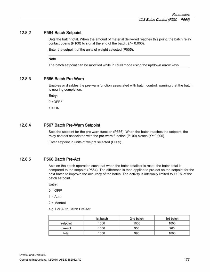
Parameters 12.8 Batch Control (P560 – P568)
BW500 and BW500/L Operating Instructions, 12/2016, A5E33482052-AD 177
12.8.2 P564 Batch Setpoint Sets the batch total. When the amount of material delivered reaches this point, the batch relay contact opens (P100) to signal the end of the batch. (f = 0.000).
Enter the setpoint of the units of weight selected (P005).
Note
The batch setpoint can be modified while in RUN mode using the up/down arrow keys.
12.8.3 P566 Batch Pre-Warn Enables or disables the pre-warn function associated with batch control, warning that the batch is nearing completion.
Entry:
0 =OFFf 1 = ON
12.8.4 P567 Batch Pre-Warn Setpoint Sets the setpoint for the pre-warn function (P566). When the batch reaches the setpoint, the relay contact associated with the pre-warn function (P100) closes (f = 0.000).
Enter setpoint in units of weight selected (P005).
12.8.5 P568 Batch Pre-Act Acts on the batch operation such that when the batch totalizer is reset, the batch total is compared to the setpoint (P564). The difference is then applied to pre-act on the setpoint for the next batch to improve the accuracy of the batch. The activity is internally limited to ±10% of the batch setpoint.
Entry:
0 = OFFf
1 = Auto
2 = Manual
e.g. For Auto Batch Pre-Act 1st batch 2nd batch 3rd batch
setpoint 1000 1000 1000 pre-act 1000 950 960
total 1050 990 1000
Parameters 12.9 Totalization (P619 - P648)
BW500 and BW500/L 178 Operating Instructions, 12/2016, A5E33482052-AD
12.8.6 P569 Manual Batch Pre-Act Amount Enter a value to make the setpoint relay change state at a known value lower than the setpoint (P564). This allows the feeding system to empty with each batch. The value of the manual pre-Act entry is generally reflective of the material that is left in the feeding system.
Example:
Setpoint = 1000
Manual Pre-Act = 50
The setpoint relay will activate when the batch totalizer reaches 950.
12.8.7 P598 Span Adjust Percentage Accessible only through manual span adjust (P019), when percent change (1) is selected. Refer to % Change.
12.9 Totalization (P619 - P648) The following parameters are specific to the use of the BW500 and BW500/L totalizers. See “Totalization (Page 103)”.
12.9.1 P619 Totaling Dropout Sets the limit, in percent of design load, below which material rates are not totalized (f = 3.0).
The value of 0 is reserved to allow both negative and positive totalization. Enter drop out value in % of design load, range is 0 to 25 %.
12.9.2 P620 Display Zero Dropout Activates the limit as defined in P619 ’Totalling Dropout’, below which, the rate and/or load are set to 0.0.
-01 = Rate
-02 = Load
Parameters 12.9 Totalization (P619 - P648)
BW500 and BW500/L Operating Instructions, 12/2016, A5E33482052-AD 179
12.9.3 P621 mA Zero Dropout Activates the limit as defined in P619 ’Totalling Dropout’, below which, the analog output, with respect to rate and load only, is set to 0.0.
Note • Valid only if P201 = 1 or 2 • BW500 has three mA outputs, BW500/L has one
12.9.4 P631 Totalizer Resolution This parameter sets the resolution of the totalizer selected.
Totalizers are:
-01 = totalizer 1
-02 = totalizer 2
-03 = verification totalizer
-04 = material test totalizer
-05 = batch totalizer1)
Entry:
1 = 0.001 (one thousandth)
2 = 0.01 (one hundredth)
3 = 0.1 (one tenth)
4 = 1 (unit)f 5 = 10 (x ten)
6 = 100 (x hundred)
7 = 1000 (x thousand) 1) Not available with the BW500/L
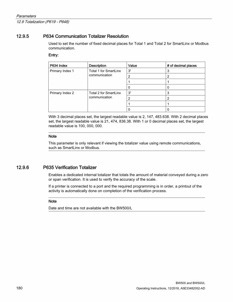
Parameters 12.9 Totalization (P619 - P648)
BW500 and BW500/L 180 Operating Instructions, 12/2016, A5E33482052-AD
12.9.5 P634 Communication Totalizer Resolution Used to set the number of fixed decimal places for Total 1 and Total 2 for SmartLinx or Modbus communication.
Entry: P634 Index Description Value # of decimal places Primary Index 1 Total 1 for SmartLinx
communication 3f 3 2 2 1 1 0 0
Primary Index 2 Total 2 for SmartLinx communication
3f 3 2 2 1 1 0 0
With 3 decimal places set, the largest readable value is 2, 147, 483.638. With 2 decimal places set, the largest readable value is 21, 474, 836.38. With 1 or 0 decimal places set, the largest readable value is 100, 000, 000.
Note
This parameter is only relevant if viewing the totalizer value using remote communications, such as SmartLinx or Modbus.
12.9.6 P635 Verification Totalizer Enables a dedicated internal totalizer that totals the amount of material conveyed during a zero or span verification. It is used to verify the accuracy of the scale.
If a printer is connected to a port and the required programming is in order, a printout of the activity is automatically done on completion of the verification process.
Note
Date and time are not available with the BW500/L
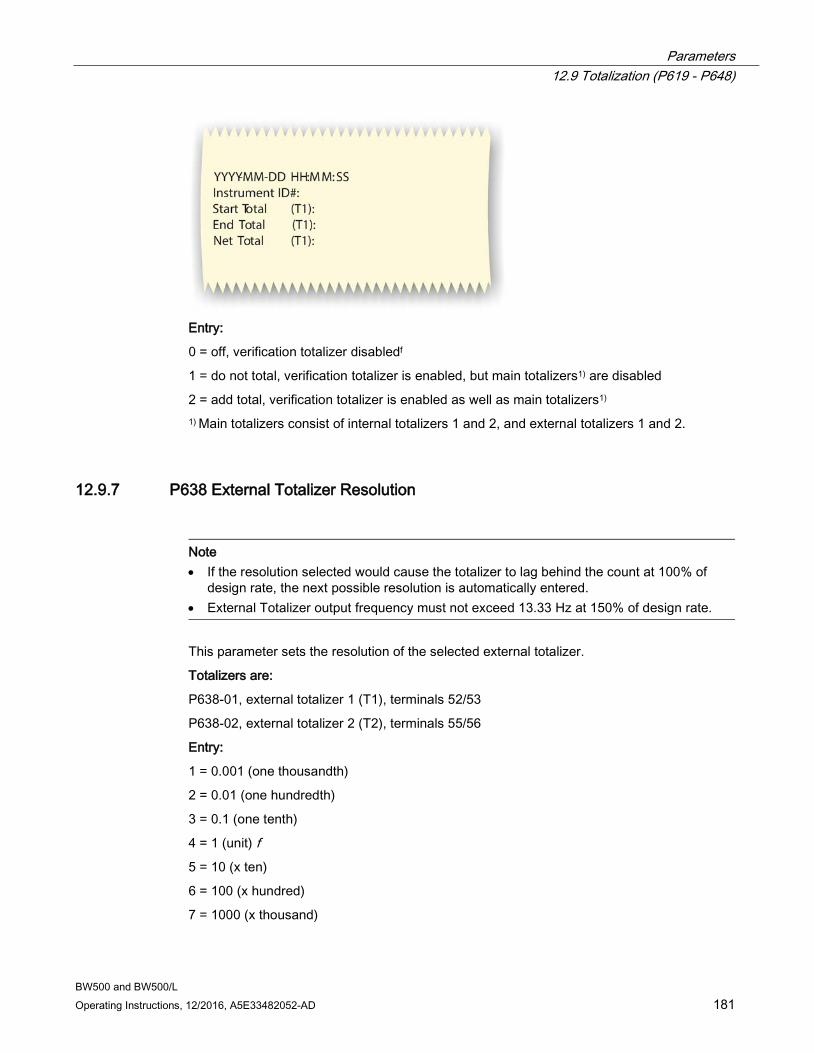
Parameters 12.9 Totalization (P619 - P648)
BW500 and BW500/L Operating Instructions, 12/2016, A5E33482052-AD 181
Entry:
0 = off, verification totalizer disabledf
1 = do not total, verification totalizer is enabled, but main totalizers1) are disabled
2 = add total, verification totalizer is enabled as well as main totalizers1) 1) Main totalizers consist of internal totalizers 1 and 2, and external totalizers 1 and 2.
12.9.7 P638 External Totalizer Resolution
Note • If the resolution selected would cause the totalizer to lag behind the count at 100% of
design rate, the next possible resolution is automatically entered. • External Totalizer output frequency must not exceed 13.33 Hz at 150% of design rate.
This parameter sets the resolution of the selected external totalizer.
Totalizers are:
P638-01, external totalizer 1 (T1), terminals 52/53
P638-02, external totalizer 2 (T2), terminals 55/56
Entry:
1 = 0.001 (one thousandth)
2 = 0.01 (one hundredth)
3 = 0.1 (one tenth)
4 = 1 (unit) f 5 = 10 (x ten)
6 = 100 (x hundred)
7 = 1000 (x thousand)
Parameters 12.9 Totalization (P619 - P648)
BW500 and BW500/L 182 Operating Instructions, 12/2016, A5E33482052-AD
12.9.8 P643 External Contact Closure Sets the duration of the contact closure, in ms, for the external totalizer selected, totalizers 1 and 2 (P643-01 or -02) (f = 30)
Permissible values are in 10 ms increments from 0. The value is automatically calculated upon entry of P011 (design rate) and P638 (totalizer 1 resolution, external) so that the duration of contact closure allows the transistor switch response to track the total, up to 150% of the design rate. The value can be changed to suit specific contact closure requirements, such as in the case of programmable logic controllers.
Note • If the duration selected causes the totalizer to lag behind the count rate, the next possible
duration is automatically entered. • External Totalizer output frequency must not exceed 13.33 Hz at 150% of design rate.
12.9.9 P647 Totalizer Display Selects the totalizer combination to be displayed, either manually through the scroll display key or automatically by control of the display mode (P081).
Entry:
1 = totalizer 1f 2 = totalizer 2
3 = totalizer 1 and 2
12.9.10 P648 Totalizer Reset, Internal Manual reset of the selected internal totalizer when the entry is made (f = 0).
Entry:
0 = no reset
1 = reset totalizer 2
2 = reset totalizers 1 and 2
Resetting the internal totalizers 1 and 2 resets the internal registers for external totalizers 1 and 2.
Parameters 12.9 Totalization (P619 - P648)
BW500 and BW500/L Operating Instructions, 12/2016, A5E33482052-AD 183
12.9.11 P680 Test Load: Weight (Options) Selects the method by which the test load is entered into P017.
1 = enter value: returns to P017 for entry of the test load value. This value is calculated by the formula: Total Mass of the test weights/average idler spacing
Example:
3 test weights each weighing 8.2 kg, idler spacing before the scale is 1225 mm, the idler spacing after the scale is 1175 mm.
The average idler spacing is 1225 +1175/2=1200 mm or 1.2 m
Total mass of test weights/average idler spacing = 3X8.2 kg/1.2 m = 24.6/1.2 = 20.5 kg/m
2 = enter data: advances to P681 and P682 for entry of required data to automatically calculate and enter the test load into P017.
12.9.12 P681 Total Mass of Test Weights For test load data entry (P680=2) this parameter is enabled for entry of the total mass of all of the test weights used for span calibration. The mass units are determined in P004 (imperial=1, metric=2).
12.9.13 P682 Average Idler Spacing For test load data entry (P680=2) this parameter is enabled for entry of the average idler space before and afer the scale. On multiple scale idler systems, this includes the entire weigh area. The length units are determined in P004 (imperial=1, metric=2).
12.9.14 P690 Speed Constant Entry Selects the method by which the speed constant is entered, for both speed sensors (P690-01 or 02)1). 1) BW500/L has only one speed input
1 = calculated, this selection returns the program to appropriate P015 for entry of speed constant:
(speed sensor pulses per revolution)/(pulley circumference (m or ft) / revolution)
e.g:
WS300-256 PPR mounted on 6” Bend Pulley
(256 pulses per revolution)/(0.478meters per revolution) = 534.694 pulses per meter or 162.975 pulses per feet
OR
2 = sensor data, the selection forwards the program to P691 and P692 for entry of the required sensor data for automatic calculation. The calculated value is automatically entered into P015-01 or 02.
Parameters 12.10 ECal Parameters (P693 – P698)
BW500 and BW500/L 184 Operating Instructions, 12/2016, A5E33482052-AD
12.9.15 P691 Drive Pulley Diameter For speed constant entry (P690 =2), this parameter is enabled for entry of the drive pulley diameter (P691-01 or 02)1).
Enter the pulley diameter (units determined in P004). 1) BW500/L has only one speed input
12.9.16 P692 Pulses Per Sensor Revolution For speed constant entry (P690 = 2), this parameter is enabled for entry of the pulses per revolution that the speed sensor delivers (P692-01 or 02)1).
Enter the pulses per revolution from the speed sensor nameplate. 1) BW500/L has only one speed input
12.10 ECal Parameters (P693 – P698) Accessible only through P017 for ECal test reference. After Ecal completion, only a zero calibration is necessary to allow access to the RUN mode.
Note
ECal is not available on six load cell belt scales.
12.10.1 P693 Load Cell Capacity Units Determines the units used for entering eCal data:
1 = kg
2 = lb
3 = Other (mV Span)1) 1) In the case of other, software jumps to P699 since data entry P694 through P698 are not applicable if P693=4.
12.10.2 P694 ECal Load Cell Capacity Enters the load cell’s weighing capacity for the selected cell (f = 1.0).
-01 = load cell A
-02 = load cell B
-03 = load cell C2)
-04 = load cell D2)
Enter the value in the units corresponding to the scale selection, e.g. in kg if P693 = 1, or lb. if P693 = 2 or 3. 2) Not available with BW500/L

Parameters 12.10 ECal Parameters (P693 – P698)
BW500 and BW500/L Operating Instructions, 12/2016, A5E33482052-AD 185
12.10.3 P695 ECal Load Cell Sensitivity Enters the load cell’s sensitivity for the selected cell (f = 1.0).
-01 = load cell A
-02 = load cell B
-03 = load cell C2)
-04 = load cell D2)
Enter the value in mV/V obtained from load cell nameplate. 2) Not available with BW500/L
12.10.4 P696 ECal Load Cell Excitation Determines the excitation applied to the load cells.
Nominally this value is 10 V. However, a measurement of the voltage at the load cell provides the most accurate entry.
Enter the load cell excitation in V DC.
12.10.5 P697 ECal Idler Spacing Enters the measured distance between the weighing idlers. Refer to the associated belt scale instruction manual (f = 1.0).
Distance units are:
feet: if the imperial system of measurement has been selected, P004 = 1
metres: if the metric system of measurement has been selected, P004 = 2
Enter the distance to three decimal points.
12.10.6 P698 ECal Conveyor Inclination Enters the inclination or declination angle of the conveyor at the point where the belt scale is installed (f = 0.0000).
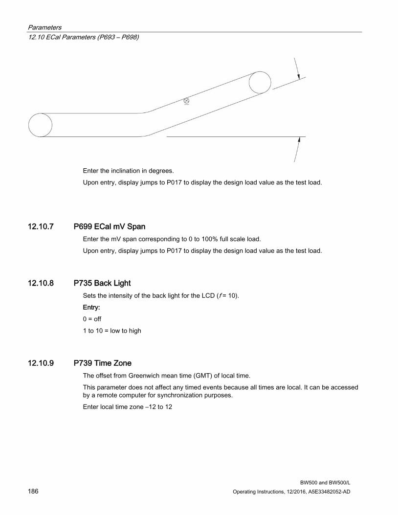
Parameters 12.10 ECal Parameters (P693 – P698)
BW500 and BW500/L 186 Operating Instructions, 12/2016, A5E33482052-AD
Enter the inclination in degrees.
Upon entry, display jumps to P017 to display the design load value as the test load.
12.10.7 P699 ECal mV Span Enter the mV span corresponding to 0 to 100% full scale load.
Upon entry, display jumps to P017 to display the design load value as the test load.
12.10.8 P735 Back Light Sets the intensity of the back light for the LCD (f = 10).
Entry:
0 = off
1 to 10 = low to high
12.10.9 P739 Time Zone The offset from Greenwich mean time (GMT) of local time.
This parameter does not affect any timed events because all times are local. It can be accessed by a remote computer for synchronization purposes.
Enter local time zone –12 to 12
Parameters 12.11 Communication (P740 - P799)
BW500 and BW500/L Operating Instructions, 12/2016, A5E33482052-AD 187
12.11 Communication (P740 - P799)
Note
Changes to these parameters are not effected until the power to the unit is turned off and then back on.
These parameters cover the various communications formats supported by the BW500 and BW500/L: serial printer, Dolphin Plus, SmartLinx, and Modbus.
12.11.1 P742 Word Order Parameter
Note
This parameter affects SmartLinx and Modbus communications
This value determines the format of all unsigned, double-register integers (UINT32), except for those in the direct parameter access. Values Description 0f most significant byte (MSB) is given first 1 least significant byte (LSB) is given first
12.11.2 P750 – P769 SmartLinx Module Specific Parameters These parameters are specific to the SmartLinx module installed. Refer to the module documentation for a list and description of the specific parameter requirements.
12.11.3 P770 – P789 Local Port Parameters These parameters are specific to programming of the BW500 and BW500/L communication ports. Refer to Communications (Page 125) for a listing and description of these parameters.
12.12 SmartLinx Hardware Testing These parameters are used to test and debug a SmartLinx card (if installed).
Parameters 12.12 SmartLinx Hardware Testing
BW500 and BW500/L 188 Operating Instructions, 12/2016, A5E33482052-AD
12.12.1 P790 Hardware Error The results of ongoing hardware tests in the communications circuitry. Values Description PASSf No errors FAIL least significant byte (LSB) is given firstError
occurred communicating with card; device will try to reinitialize communications with card. If mes-sage continues, record values in P791 and P792 and contact your local Siemens representative.
ERR1 No module installed, or module not supported; SmartLinx communications have been disabled
If FAIL or ERR1 is displayed in P790 (Hardware Error), go to P791 (Hardware Error Code) and P792 (Hardware Error Count) for information about the error.
12.12.2 P791 Hardware Error Code Indicates the precise cause of Fail or ERR1 condition from P790. Values Description 0f No errors Any other value Error code; provide this code to your Siemens
representative for troubleshooting
12.12.3 P792 Hardware Error Count A count that increments by 1 each time Fail is reported in P790 (Hardware Error). Values Description Range: 0 to 9999 Error count; provide this number to your Siemens
representative for troubleshooting.
12.12.4 P794 SmartLinx Module Type This parameter is used to identify the module type when SmartLinx is used. If you are not using SmartLinx, this parameter is not functional. Please see the associated SmartLinx instruction manual for a full description of this parameter.
Parameters 12.13 Test and Diagnostic (P900 - P951)
BW500 and BW500/L Operating Instructions, 12/2016, A5E33482052-AD 189
12.12.5 P795 SmartLinx Protocol This parameter is used to identify the protocol when SmartLinx is used. If you are not using SmartLinx, this parameter is not functional. Please see the associated SmartLinx instruction manual for a full description of this parameter.
If a SmartLinx module is not configured, P795 will have a value of either 255 or 0.
12.12.6 P799 Communications Control Assigns programming control through the local keypad (or Dolphin Plus, P770 = 1), or through a Modbus protocol (P770 = 2 or 3)
Entry:
0 = local
1 = modbus
12.13 Test and Diagnostic (P900 - P951)
Note
These parameters are used for test and diagnostic purposes.
12.13.1 P900 Software Revision Displays the EPROM (Flash ROM) software revision level.
12.13.2 P901 Memory Test Tests the memory. Test is initiated by scrolling to the parameter or repeated by 'pressing enter'
Display:
PASS = normal
FAIL = consult Siemens.

Parameters 12.13 Test and Diagnostic (P900 - P951)
BW500 and BW500/L 190 Operating Instructions, 12/2016, A5E33482052-AD
12.13.3 P911 mA Output Test Tests the mA output value for the output selected, outputs 1 to 3 (P911 -01 to -03)1)
Displays the value from the previous measurement. A test value can be entered and the displayed value is transmitted to the output. Upon returning to the RUN mode, the parameter assumes the actual mA output level (f = 0).
Use the UP and DOWN arrow to scroll the value 1) BW500/L has one output only
12.13.4 P914 mA Input Value Displays the current mA input value for the input selected, inputs 1 to 2 (P914 – 01 to -02).
Note • Not applicable if mA I/O board is not connected. • Not available for BW500/L
12.13.5 P918 Speed Input Frequency Displays the frequency of the speed input signal in Hertz.
12.13.6 P931 Running Totalizer 1 = Total 1
2 = Total 2
3 = Verification Total
4 = Material Test Load
5 = Batch Total
6 = NTEP Total
7 = 0Cal Start Total
8 = 0Cal End Total
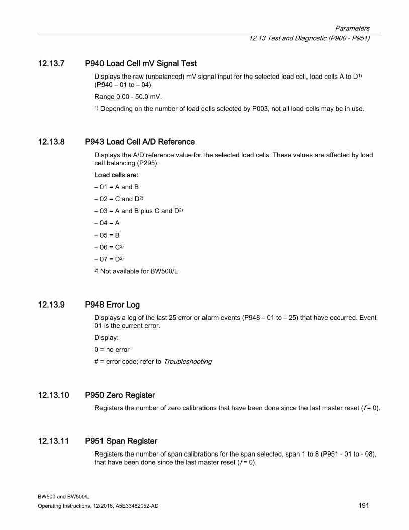
Parameters 12.13 Test and Diagnostic (P900 - P951)
BW500 and BW500/L Operating Instructions, 12/2016, A5E33482052-AD 191
12.13.7 P940 Load Cell mV Signal Test Displays the raw (unbalanced) mV signal input for the selected load cell, load cells A to D1) (P940 – 01 to – 04).
Range 0.00 - 50.0 mV. 1) Depending on the number of load cells selected by P003, not all load cells may be in use.
12.13.8 P943 Load Cell A/D Reference Displays the A/D reference value for the selected load cells. These values are affected by load cell balancing (P295).
Load cells are:
– 01 = A and B
– 02 = C and D2)
– 03 = A and B plus C and D2)
– 04 = A
– 05 = B
– 06 = C2)
– 07 = D2) 2) Not available for BW500/L
12.13.9 P948 Error Log Displays a log of the last 25 error or alarm events (P948 – 01 to – 25) that have occurred. Event 01 is the current error.
Display:
0 = no error
# = error code; refer to Troubleshooting
12.13.10 P950 Zero Register Registers the number of zero calibrations that have been done since the last master reset (f = 0).
12.13.11 P951 Span Register Registers the number of span calibrations for the span selected, span 1 to 8 (P951 - 01 to - 08), that have been done since the last master reset (f = 0).

Parameters 12.13 Test and Diagnostic (P900 - P951)
BW500 and BW500/L 192 Operating Instructions, 12/2016, A5E33482052-AD
12.13.12 P952 Design Load Displays the value of the design load, which corresponds to the full scale value for alarm and mA output functions. The design load is calculated, based on the design rate and design speed (f = 0.00).
12.13.13 P999 Master Reset Resets parameters and totalizers to their factory setting (f = 0).
Enter 9 to execute the reset.
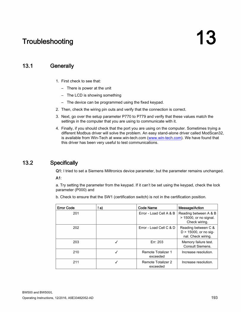
BW500 and BW500/L Operating Instructions, 12/2016, A5E33482052-AD 193
Troubleshooting 13 13.1 Generally
1. First check to see that:
– There is power at the unit
– The LCD is showing something
– The device can be programmed using the fixed keypad.
2. Then, check the wiring pin outs and verify that the connection is correct.
3. Next, go over the setup parameter P770 to P779 and verify that these values match the settings in the computer that you are using to communicate with it.
4. Finally, if you should check that the port you are using on the computer. Sometimes trying a different Modbus driver will solve the problem. An easy stand-alone driver called ModScan32, is available from Win-Tech at www.win-tech.com (www.win-tech.com). We have found that this driver has been very useful to test communications.
13.2 Specifically Q1: I tried to set a Siemens Milltronics device parameter, but the parameter remains unchanged.
A1:
a. Try setting the parameter from the keypad. If it can’t be set using the keypad, check the lock parameter (P000) and
b. Check to ensure that the SW1 (certification switch) is not in the certification position. Error Code ! a) Code Name Message/Action
201 Error - Load Cell A & B Reading between A & B > 15000, or no signal.
Check wiring. 202 Error - Load Cell C & D Reading between C &
D > 15000, or no sig-nal. Check wiring.
203 ✓ Err: 203 Memory failure test. Consult Siemens.
210 ✓ Remote Totalizer 1 exceeded
Increase resolution.
211 ✓ Remote Totalizer 2 exceeded
Increase resolution.
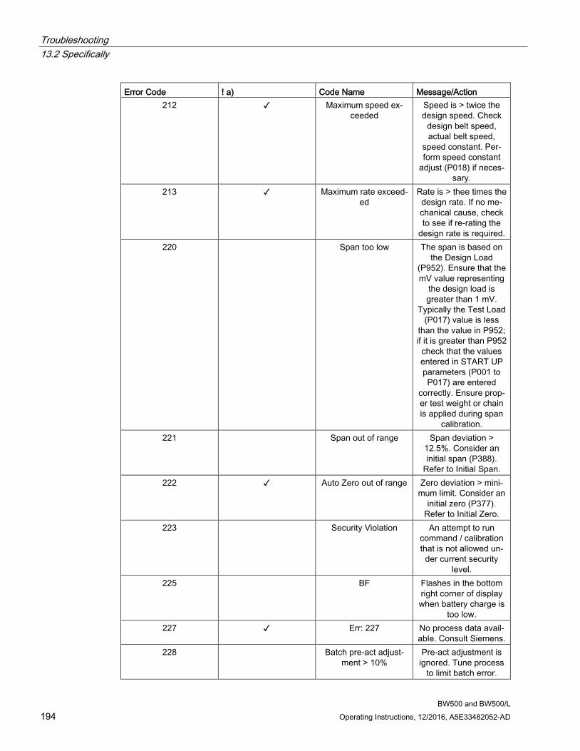
Troubleshooting 13.2 Specifically
BW500 and BW500/L 194 Operating Instructions, 12/2016, A5E33482052-AD
Error Code ! a) Code Name Message/Action 212 ✓ Maximum speed ex-
ceeded Speed is > twice the design speed. Check
design belt speed, actual belt speed,
speed constant. Per-form speed constant
adjust (P018) if neces-sary.
213 ✓ Maximum rate exceed-ed
Rate is > thee times the design rate. If no me-chanical cause, check to see if re-rating the
design rate is required. 220 Span too low The span is based on
the Design Load (P952). Ensure that the mV value representing
the design load is greater than 1 mV.
Typically the Test Load (P017) value is less
than the value in P952; if it is greater than P952
check that the values entered in START UP parameters (P001 to P017) are entered
correctly. Ensure prop-er test weight or chain is applied during span
calibration. 221 Span out of range Span deviation >
12.5%. Consider an initial span (P388).
Refer to Initial Span. 222 ✓ Auto Zero out of range Zero deviation > mini-
mum limit. Consider an initial zero (P377).
Refer to Initial Zero. 223 Security Violation An attempt to run
command / calibration that is not allowed un-
der current security level.
225 BF Flashes in the bottom right corner of display when battery charge is
too low. 227 ✓ Err: 227 No process data avail-
able. Consult Siemens. 228 Batch pre-act adjust-
ment > 10% Pre-act adjustment is
ignored. Tune process to limit batch error.

Troubleshooting 13.2 Specifically
BW500 and BW500/L Operating Instructions, 12/2016, A5E33482052-AD 195
Error Code ! a) Code Name Message/Action 240 Integrator not config-
ured P002-P017 must be
programmed 241 ✓ No PID mA Input PID Process Value
Source (P402) or PID Setpoint (P414) has
been programmed for a mA Input, however mA Input Function (P255)
has not been pro-grammed properly.
242 ✓ No PID mA Output PID System (P400) has been turned on, but mA Output (P201) has not
been programmed properly.
243 No batch setpoint relay Batch has been set up, but no relay has been configured for a set-
point. 244 ✓ No speed relay Second speed sensor
configured, but no relay is assigned
PF Power Failure Displayed at the bottom right corner of the dis-play if power is inter-
rupted after the integrator has been
calibrated. a) The codes in this column with checkmarks will produce relay output for a diagnostic alarm.

Troubleshooting 13.2 Specifically
BW500 and BW500/L 196 Operating Instructions, 12/2016, A5E33482052-AD

BW500 and BW500/L Operating Instructions, 12/2016, A5E33482052-AD 197
Certification 14 14.1 Certification
For installations requiring trade certification, the BW500 and BW500/L provides a certification compliance switch. Refer to the layout diagram.
After certification of the installation has been obtained, the switch is set. The switch must be positioned to the left to enable trade certification compliance.
When the switch is set for certification, editing most parameter values, span calibrations, and main totalizer reset are denied. The maximum acceptable deviation from one zero calibration to another is limited to an accumulated ± 2% of the zero value, and the totalizer dropout (P619) is limited to 3% or less, when the certification switch is set.
To set the certification switch, disconnect power before opening the enclosure lid.
● slide switch to the left position
● close the lid
● reconnect the power
Note
Not available with BW500/L.
14.2 Parameters unlocked when certification switch is set: P000 Security Lock P009 Time P100 Relay Function (if P100 is set to ’11 - Certification
Rate alarm’, P100 will be locked) P560 - P569 Batch Control Functions P648 Totalizer Reset. Unlock entry #1 P080 Damping Display P081 Display scroll mode P400 - P419 PID P631 Lock index ’01’, unlock remaining index ’02 - 05’ P634 Unlock P635 Unlock P647 Unlock
Certification 14.3 Certification Printing
BW500 and BW500/L 198 Operating Instructions, 12/2016, A5E33482052-AD
14.3 Certification Printing Certification printing is allowed if the following conditions are met:
● certification switch is set
● rate is below 2 %
● a communications port has been programmed for a printer
The printout must consist of the following:
● Date: YYYY-MM-DD
● Time: HH:MM:SS
● Instrument ID#: Belt Scale serial number
● Units: Units set in P005
● Start Total: End total of previous print
● End Total: Accumulated totalizer including Start Total
● Net Total: End total minus Start Total
If a power failure occurs during totalization, power failure indicator “PF” will be printed in the middle of a new line, even if it has been cleared from the screen. “PF” will be cleared from the screen after printing.
BW500 and BW500/L Operating Instructions, 12/2016, A5E33482052-AD 199
Appendix A A.1 Appendix I
A.1.1 Memory Backup The BW500 and BW500/L requires no maintenance or cleaning, other than a periodic replacement of the memory backup battery. Refer to Installing/replacing the back-up battery (Page 44).
A.1.2 Software Updates Software updates require Siemens Dolphin Plus software, contact your local Siemens representative.
It is recommended that the old software and parameters be saved to your PC before downloading the new software.
Once installed, a master reset (P999) must be done.
The parameters can then be reloaded, either manually or downloaded from the previously saved file. If downloading parameters via Dolphin Plus, confirm that BW500 and BW500/L is in PROGRAM mode. The zero and span values are included in the parameter file, However, new zero and span calibrations should be done regardless, and as soon as possible to ensure operating accuracy.
A.1.3 Calibration Criteria Zero
● belt must be empty. Run the conveyor for several minutes to limber the belt and ensure that it is empty.
● test weights or chain are not used during a zero calibration
● conveyor running at normal speed
● moisture input not used during a zero calibration
● inclination will be used if feature is activated
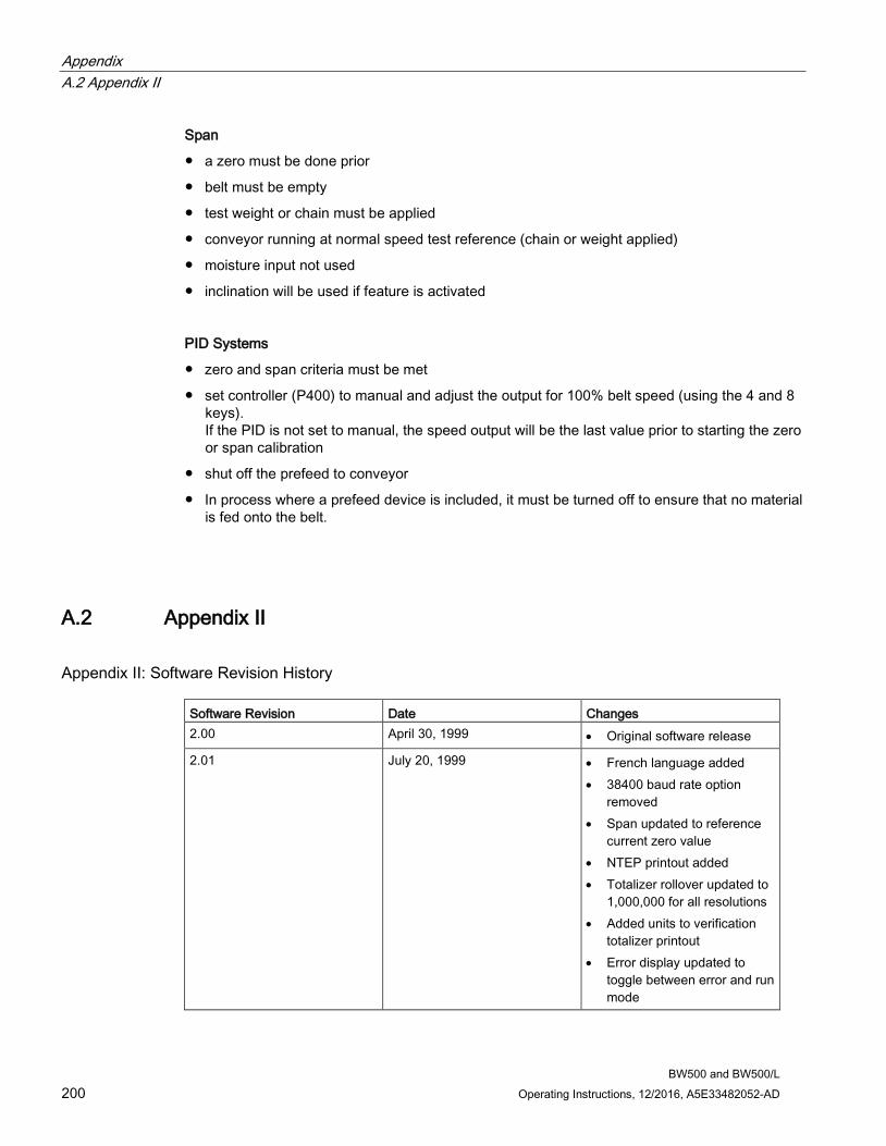
Appendix A.2 Appendix II
BW500 and BW500/L 200 Operating Instructions, 12/2016, A5E33482052-AD
Span
● a zero must be done prior
● belt must be empty
● test weight or chain must be applied
● conveyor running at normal speed test reference (chain or weight applied)
● moisture input not used
● inclination will be used if feature is activated
PID Systems
● zero and span criteria must be met
● set controller (P400) to manual and adjust the output for 100% belt speed (using the 4 and 8 keys). If the PID is not set to manual, the speed output will be the last value prior to starting the zero or span calibration
● shut off the prefeed to conveyor
● In process where a prefeed device is included, it must be turned off to ensure that no material is fed onto the belt.
A.2 Appendix II
Appendix II: Software Revision History Software Revision Date Changes 2.00 April 30, 1999 • Original software release
2.01 July 20, 1999 • French language added • 38400 baud rate option
removed • Span updated to reference
current zero value • NTEP printout added • Totalizer rollover updated to
1,000,000 for all resolutions • Added units to verification
totalizer printout • Error display updated to
toggle between error and run mode
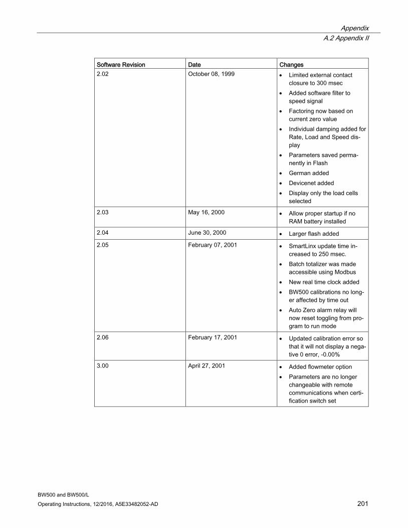
Appendix A.2 Appendix II
BW500 and BW500/L Operating Instructions, 12/2016, A5E33482052-AD 201
Software Revision Date Changes 2.02 October 08, 1999 • Limited external contact
closure to 300 msec • Added software filter to
speed signal • Factoring now based on
current zero value • Individual damping added for
Rate, Load and Speed dis-play
• Parameters saved perma-nently in Flash
• German added • Devicenet added • Display only the load cells
selected
2.03 May 16, 2000 • Allow proper startup if no RAM battery installed
2.04 June 30, 2000 • Larger flash added
2.05 February 07, 2001 • SmartLinx update time in-creased to 250 msec.
• Batch totalizer was made accessible using Modbus
• New real time clock added • BW500 calibrations no long-
er affected by time out • Auto Zero alarm relay will
now reset toggling from pro-gram to run mode
2.06 February 17, 2001 • Updated calibration error so that it will not display a nega-tive 0 error, -0.00%
3.00 April 27, 2001 • Added flowmeter option • Parameters are no longer
changeable with remote communications when certi-fication switch set

Appendix A.2 Appendix II
BW500 and BW500/L 202 Operating Instructions, 12/2016, A5E33482052-AD
Software Revision Date Changes 3.01 July 17, 2001 • Increased maximum idle
time for SmartLinx to 9999 seconds
• Fixed totalizer error when load is negative and totalizer drop out is 0.00
• Allowed acces to P635 in certification mode
• Setting of certification switch changes totalizer dropout to 0.00
3.02 August 07, 2001 • Fixed bug in totalizer P619 totalizer dropout
3.03 February 20, 2002 • Fixed timing issue with inter-val printing
• Added % rate and % load to PID setpoint configuration, P414
• Updated Auto Zero to allow run display to be seen, AZ now flashes in bottom right hand corner of display
• Updated span adjust calcu-lation
• Increased totalizer resolution to 100,000,000
• Improved error interruption on display
• Fixed zero and span calibra-tion using remote communi-cations
3.04 May 09, 2002 • Fixed SmartLinx error check-ing
• Fixed error with discrete inputs
• Added P419 PID freeze enable/disable
• Updated zero calibration when certification switch set, now references last operator initiated zero prior certifica-tion switch set
• Added power failure indica-tor on display, "PF"
• Added online calibration
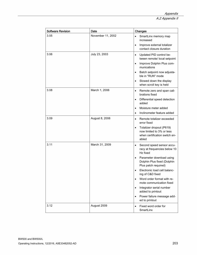
Appendix A.2 Appendix II
BW500 and BW500/L Operating Instructions, 12/2016, A5E33482052-AD 203
Software Revision Date Changes 3.05 November 11, 2002 • SmartLinx memory map
increased • Improve external totalizer
contact closure duration
3.06 July 23, 2003 • Updated PID control be-tween remote/ local setpoint
• Improve Dolphin Plus com-munications
• Batch setpoint now adjusta-ble in "RUN" mode
• Slowed down the display when scroll key is held
3.08 March 1, 2006 • Remote zero and span cali-brations fixed
• Differential speed detection added
• Moisture meter added • Inclinometer feature added
3.09 August 8, 2006 • Remote totalizer exceeded error fixed
• Totalizer dropout (P619) now limited to 3% or less when certification switch en-abled
3.11 March 31, 2009 • Second speed sensor accu-racy at frequencies below 10 Hz fixed
• Parameter download using Dolphin Plus fixed (Dolphin Plus patch required)
• Electronic load cell balanc-ing of C&D fixed
• Word order format with re-mote communication fixed
• Integrator serial number added to printout
• Power failure message add-ed to printout
3.12 August 2009 • Fixed word order for SmartLinx
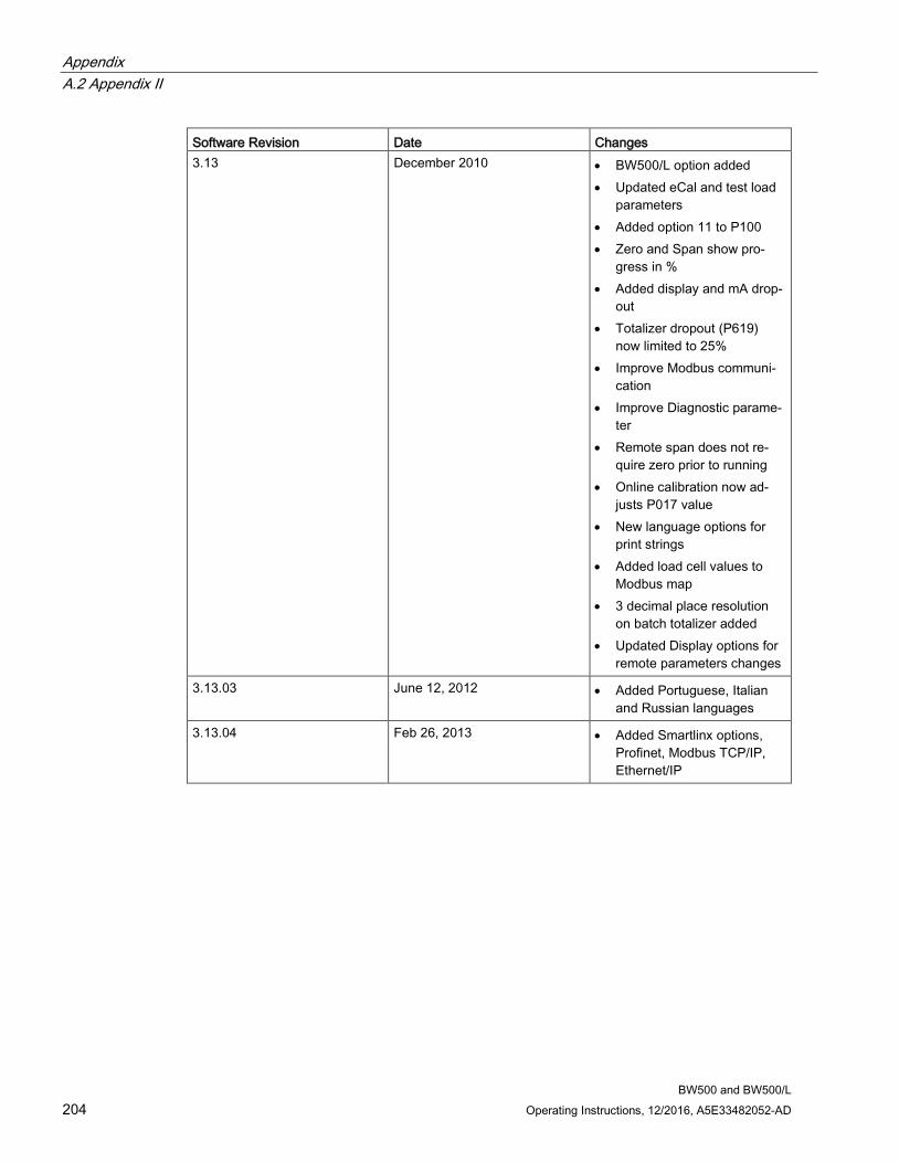
Appendix A.2 Appendix II
BW500 and BW500/L 204 Operating Instructions, 12/2016, A5E33482052-AD
Software Revision Date Changes 3.13 December 2010 • BW500/L option added
• Updated eCal and test load parameters
• Added option 11 to P100 • Zero and Span show pro-
gress in % • Added display and mA drop-
out • Totalizer dropout (P619)
now limited to 25% • Improve Modbus communi-
cation • Improve Diagnostic parame-
ter • Remote span does not re-
quire zero prior to running • Online calibration now ad-
justs P017 value • New language options for
print strings • Added load cell values to
Modbus map • 3 decimal place resolution
on batch totalizer added • Updated Display options for
remote parameters changes
3.13.03 June 12, 2012 • Added Portuguese, Italian and Russian languages
3.13.04 Feb 26, 2013 • Added Smartlinx options, Profinet, Modbus TCP/IP, Ethernet/IP
Appendix A.3 Technical support
BW500 and BW500/L Operating Instructions, 12/2016, A5E33482052-AD 205
A.3 Technical support
Technical Support If this documentation does not provide complete answers to any technical questions you may have, contact Technical Support at:
● Support request (http://www.siemens.com/automation/support-request)
● More information about our Technical Support is available at Technical Support (http://www.siemens.com/automation/csi/service)
Internet Service & Support In addition to our documentation, Siemens provides a comprehensive support solution at:
● Services & Support (http://www.siemens.com/automation/service&support)
Personal contact If you have additional questions about the device, please contact your Siemens personal contact at:
● Partner (http://www.automation.siemens.com/partner)
In order to find the contact for your product, select under 'All Products and Branches' the path 'Automation Technology > Sensor Systems'.
Documentation You can find documentation on various products and systems at:
● Instructions and manuals Instructions and manuals (http://www.siemens.com/processinstrumentation/documentation)

Appendix A.3 Technical support
BW500 and BW500/L 206 Operating Instructions, 12/2016, A5E33482052-AD
BW500 and BW500/L Operating Instructions, 12/2016, A5E33482052-AD 207
Glossary
Auto Zero Allows a zero calibration to be performed automatically in RUN mode when the load drops below the preset amount (P371) of design for 1 complete calibration period (P360).
Auxiliary Inputs Can be programmed to allow the use of an external contact to provide the following functions, display scroll, totalizer 1 reset, Zero, Span, Multispan, Print, Batch reset, or PID functions.
Batching The accumulation of a predetermined quantity of material.
Contacts A junction of electrical conductors in open (not connected) or closed (connected) states.
Damping Provides control over the speed at which the displayed rate, load, speed readings, and output functions are updated in response to changes in the internal rate signals.
Design Rate This is the maximum material flow rate for this particular application (100% full scale).
Differential Speed Difference in speed at two points in a mechanical system.
Direct Span If replacing software or hardware, this allows the entry of the previously recorded span value.
Direct Zero If replacing software or hardware, this allows the entry of the previously recorded zero value.
Glossary
BW500 and BW500/L 208 Operating Instructions, 12/2016, A5E33482052-AD
Factoring Used to calculate the test load value of a new or unknown test weight using the current span as reference.
Inclinometer Accepts incline information about conveyor or scale.
Initial Span Usually the first span performed, it is used as reference for all other spans to determine whether they have deviated beyond the accumulated +/- 12.5%.
Initial Zero Usually the first zero performed, it is used as reference for all other zeros to determine whether they have deviated beyond the Zero Limit (P370).
Input/Output Trim Allows the 4 and 20 mA values to be adjusted and verified with an external source (meter).
Linearization Compensates for non-linear output of the belt scale caused by varying load rates.
Load Cell Strain Gauge type transducer that produces an electrical output proportional to force (load) applied.
LVDT An electromechanical transducer that produces an electrical output proportional to the displacement of a separate movable core.
mA A unit of measure for current flow, milliamperes.
Material Test Material samples used to verify the accuracy of the span calibration.
Glossary
BW500 and BW500/L Operating Instructions, 12/2016, A5E33482052-AD 209
Modbus An industry standard protocol used by popular SCADA and HMI systems.
Moisture sensor A mA input function to incorporate moisture reading from an external moisture sensor.
Multispan Since every material has its own unique physical properties, and may impact differently, a span calibration is required for each material to realize maximum accuracy.
PID Proportional Integral Derivative control is used to control the feed rate to a setpoint, either internal to the BW500 or external.
RAM Random Access Memory.
Random Access Memory Memory that has both read and write capabilities.
Relay An electromechanical device with contacts that can be closed or opened by energizing a coil.
Routine Span Any operator initiated span calibration.
Routine Zero Any operator initiated zero calibration.
Setpoint A value that the integrator is trying to match.
SmartLinx An interface to popular industrial communication systems.
Glossary
BW500 and BW500/L 210 Operating Instructions, 12/2016, A5E33482052-AD
SPA Single Parameter Access, used to view or edit parameters through the available communication ports.
Span This is a count value representing the mV signal provided by either the LVDT or Load Cell at 100% design load.
Span Register This is the number of span calibrations that have been performed since the last master reset.
Test Weight A calibrated weight which will represent a certain load on the scale.
Totalizer An incremental counter that records the total of material that has been monitored.
Zero Register Shows the number of zero calibrations that have been performed since the last master reset.
BW500 and BW500/L Operating Instructions, 12/2016, A5E33482052-AD 211
Index
A
alarm condition, 102, 160 display, 124 event, 123 function, 158 high, 159 mode, 159
Approvals, 20 Auto Zero, 76 Autobaud, 129 Auxiliary Input, 83, 83, 83 Auxiliary Input, 83, 83, 83 Auxiliary Input, 83, 83, 83
B
balancing, 57 batching, 121 baud rate, 128, 148 belt speed compensation, 67 bit values, 146
C
Cable, 19 calibration
online, 19, 87, 88, 168, 204 calibration
ECal, 57, 156, 184, 184 initial, 57, 63, 74, 78, 80, 82 online, 19, 87, 88, 168, 204
calibration initial, 57, 63, 74, 78, 80, 82
calibration ECal, 57, 156, 184, 184
calibration online, 19, 87, 88, 168, 204
calibration ECal, 57, 156, 184, 184
calibration ECal, 57, 156, 184, 184
calibration online, 19, 87, 88, 168, 204
Calibration online, 85
Command Controls, 143 communication
configuration ports, 127 ports, 125
communications, 125 configuring ports, 127 ports, 15, 127 protocol, 127, 128
Communications, 19 configuring communication ports, 127 Connections, 82, 107 control
feed forward, 113 integral, 112 output, 112 PID, 114, 161 proportional, 112 rate, 107 system, 112
controller function, 117 logic, 104, 182 PID, 107, 114 setpoint, 107
Customer Support Hotline, 205
D
Damping, 100 data
advanced access, 139 bits, 129 types, 146
Date and Time, 141 deviation
alarm, 102 Device Identifier, 139 Device State, 142 Diagnostic, 145 Dial-up modem, 125 Direct span, 80 direct zero, 75 discrete
input, 18 Dolphin, 16
Plus, 16, 125, 127, 132
Index
BW500 and BW500/L 212 Operating Instructions, 12/2016, A5E33482052-AD
Dolphin" protocol, 132
E
Ecal, 184 ECal, 64 error
check, 134 codes, 141 handling, 150
error" messages, 150
example modem setup, 148 External Totalizer, 105
F
factoring, 90, 91 Format register, 138, 141 Format Register, 140 function, 18
alarm, 102 output, 102 pre-act, 124
H
Handshaking Area, 139 Hanging Up, 130 High Alarm, 159 Hotline, 205
I I/O board, 118 Incline compensation, 99 initial span, 78 initial startup, 114 initial zero, 72, 74 Input, 18 Installation, 21, 25 installing or replacing the battery, 44 Instrumentation I/O, 15 Internet, 205
K
Key, 48
L
Leased line modem, 125 linearization, 92 load cell, 17 load cells, 57 LVDT, 17, 34
M
mA, 18, 118 analog, 15 I/O board, 107 input, 101, 118, 161 output, 117, 161 output test, 190
Main entry, 149 Mapping, 139 maximum separation, 126 Milltronics BW500, 15 Milltronics BW500 and BW500/L features, 15 Milltronics BW500/L, 15 Modbus, 133
how modbus works, 133 protocol, 125, 133 responses, 149 RTU/ASCII protocol, 133
Modbus RTU Software, 148 modem, 125 modems, 125, 147
available, 129 example setup, 148 hanging up, 130 inactivity timeout, 130 picking, 147 setting up, 147 setup, 147
modes run mode, 69
Moisture Compensation, 98 mounting
wall mount, 25 Mounting the Enclosure, 24 multispan, 81, 91
N
network address, 128, 131, 131, 134 Non metallic enclosure, 21 non-linearity, 92
Index
BW500 and BW500/L Operating Instructions, 12/2016, A5E33482052-AD 213
O
Online Calibration, 85 Options, 19 Output, 18, 101
P
P388 and enter EDIT mode, 79 P392 linearizer compensation %, 172 P771 (IP) network address, 128, 130, 131 P772 (IP) baud rate, 128 P774 (IP) data bits, 129 P775 (IP) stop bits, 129 P778 (IP) modem available, 129 P779 (G) modem inactivity timeout, 130 parameter, 172
P000 security lock, 153 P001 language, 153 P002 test reference selection, 153 P003 number of load cells, 154 P004 rate measurement system, 154 P005 design rate units, 154 P008 date, 154 P009 time, 155 P011 design rate, 155 P014 design speed, 155 P015 speed constant, 155 P016 belt length, 156 P017 test rate, 156 P019 manual span adjust, 157 P022 minimum speed frequency, 157 P080 damping display, 157 P081 display scroll mode, 158 P100 relay function, 158 P101 high alarm/deviation alarm, 159 P102 low alarm, 159 P107 relay alarms, 159 P118 relay logic, 160 P119 relay override, 160 P200 mA output range, 161 P201 mA output function, 161 P204 mA output average, 161 P212 mA output minimum, 162 P213 mA output maximum, 162 P214 mA output trim, 162 P215 20 mA output trim, 162 P220 mA output damping, 162 P250 mA input range, 163 P255 mA input function, 163 P261 mA input trim, 163 P262 mA input trim, 164
P270 auxilliary input function, 165 P341 days of service, 167 P350 calibration security, 168 P355 online calibration feature, 168 P356 online calibration reference weight, 168 P357 online calibration limits, 169 P359 factoring, 169 P360 calibration duration, 169 P365 multispan, 170 P367 direct zero entry, 170 P370 zero limit deviation, 171 P370 zero limit deviation %, 171 P371 auto zero initiation upper limit, 171 P377 initial zero, 171 P388 initial span, 171 P390 linearizer, 172 P391 linearizer load points, 172 P398 moisture content, 172 P398-02 moisture content, 172 P399 incline sensing, 173 P400 PID system, 173 P401 PID update time, 173 P402 PID process value source, 174 P405 proportional terms, 174 P406 integral term, 174 P407 derivative term, 174 P408 feed forward term, 174 P410 manual mode output, 175 P414 setpoint configuration, 175 P415 local set point value, 175 P416 external setpoint, 176 P418 remote setpoint ratio, 176 P419 PID freeze option, 176 P560 batch mode control, 176 P564 batch setpoint, 177 P566 batch pre-warn, 177 P567 batch pre-warn setpoint, 177 P568 batch pre-act, 177 P569 manual batch pre-act amount, 178 P598 span adjust percentage, 178 P619 totaling dropout, 178 P620 display zero dropout, 178 P631 totalizer resolution, 179 P634 communication totalizer resolutions, 180 P635 verification totalizer, 180 P638 external totalizer resolution, 181 P643 external contact closure, 182 P647 totalizer display, 182 P648 totalizer reset, internal, 182 P690 speed constant entry, 183 P691 drive pulley diameter, 184 P692 pulses per sensor revolution, 184
Index
BW500 and BW500/L 214 Operating Instructions, 12/2016, A5E33482052-AD
P693 load cell capacity units, 184 P694 Ecal load cell capacity, 184 P695 Ecal load cell sensitivity, 185 P696 Ecal load cell excitation, 185 P697 Ecal idler spacing, 185 P699 Ecal mV span, 186 P735 back light, 186 P739 time zone, 186 P770 (IP) protocol, 127 P770-P789 Local port parameters, 187 P773 parity, 128 P781 data message, 131 P794 SmartLinx module type, 188 P795 SmartLinx protocol, 189 P901 memory test, 189 P911 mA output test, 190 P914 mA input value, 190 P918 speed input frequency, 190 P931 running totalizer, 190 P940 load cell mV signal test, 191 P943 load cell A/D reference, 191 P948 error log, 191 P999 master reset, 192 relay dead band, 160
parameters P358 online calibration activation, 169 P750 - P769 SmartLinx module specific parameter, 187 P771 protocol address, 128 P790 hardware error, 188 P792 hardware error count, 188 parity, 128 read and write, 139 reading, 139 SmartLinx hardware testing, 187 values, 141 writing, 139
paramter P799 communications control, 189
PID, 18, 102, 114 function, 101 manual mode, 117 setpoint, 101, 163 setup and tuning, 114, 114
PID, 18, 102, 114 PID control, 107 PID Systems, 200 PID Tuning, 145 product ID, 139 PROGRAM, 47 protocol, 127
R
Radio modem, 125 RAM, 17 rate
control, 107, 114 Reading Parameters, 139 Refer to, 25 Register Map, 135, 138 relay, 107, 121, 123, 158, 159, 159, 160, 160
alarm, 102 contacts, 18 functions, 159
relay batch, 177
relay setpoint, 178
relay/, 158 remote
setpoint, 176 reset
master, 105, 192 reset a parameter value, 51 RS232 Port 3, 41 RUN, 47 RUN mode, 65
S
SCADA, 125 Service, 205 setpoint, 177
batch, 123 local, 175 PID, 163 rate, 114 relay, 178 remote, 176
Slave, 148 SmartLinx, 125, 126, 127 Software updates, 199 span, 80, 170
adjust, 68, 72 calibation, 82 calibration, 68, 72, 81, 84, 92 correction, 81 direct, 80 initial, 78, 80, 82 multispan, 81, 82 mV, 186 recalibration, 74, 75 remote, 82
Index
BW500 and BW500/L Operating Instructions, 12/2016, A5E33482052-AD 215
routine, 77 verification, 180
Span, 200 span adjust value, 69 Span Calibration, 64 Specification, 17 stop bits, 129 Support, 205
T
term derivative, 112, 174 forward, 174 integral, 174 proportional, 174
test load, 68, 91, 169, 186 material, 68, 94, 173 value, 190
Text Messages, 146 To access parameter directly, 49 To change a parameter value, 50 To select a parameter, 49 totalization, 103 totalizer, 103, 104, 182
functions, 103 internal, 180 master, 103
totalizer, 103, 104, 182 totalizer, 103, 104, 182 troubleshooting, 193
W
web site, 133 Weight, 20 wiring
9-pin to RJ-11, 42, 44 guidelines, 126
Writing Parameters, 139
Z
zero, 18 calibration, 63, 90 direct, 75 initial, 74 recalibration, 72
routine, 72 verification, 180
Zero, 199

Index
BW500 and BW500/L 216 Operating Instructions, 12/2016, A5E33482052-AD


Printed in Canada
Peterborough, ONCanada K9J 7B1
Subject to change without prior notice
For more information
www.siemens.com/processautomation
www.siemens.com/level
www.siemens.com/weighing
Siemens Canada Limited1954 Technology DriveP.O. Box 4225
© Siemens AG 2016A5E33482052 Rev. AD
11 mm 48 mm 66 mm
Letter without trimming
60
mm
12 mm Bufferzone
12 mm Bufferzone
Background coolgray 100 %,
Texts are filled from bottom to top
Bereich für Codes
Siemens Sans OT, Roman, 7,5 PT, schwarzAbsatzformat: 02 Adresse 7,5 pt
Siemens Sans OT, Bold, 13 PT, schwarzAbsatzformat: 01 Weitere Info 13 pt
Siemens Sans OT, Roman, 9 PT, schwarzAbsatzformat: 01 Info Text 9 pt
Siemens Sans OT, Bold, 9 PT, schwarzAbsatzformat: 01 Info Link 9 pt
Siemens Sans OT, Bold, 9 PT, schwarzAbsatzformat: 03 siemens.com 9 pt
Ho
rizo
nt
imm
er a
uf
60
mm
Find any font sizes for the text fields in the Panel "Paragraph styles"!