Embed Size (px)
Citation preview

The Babcock & Wilcox Company 1
B&W IR-CFB Operating Experience andNew Development
BR-1765
Technical Paper
M.Maryamchik and D.L. WietzkeThe Babcock & Wilcox CompanyBarberton, Ohio, U.S.A.
Presented to:18th International Conference on Fluidized BedCombustionMay 22 - 25, 2005Toronto, Ontario, Canada
1 © 2005 The Babcock & Wilcox Company. All rights reserved.
Proceedings of FBC2005 18th International Conference on Fluidized Bed Combustion
May 22-25, 2005, Toronto, Ontario, Canada
BR-1765
B&W IR-CFB: OPERATING EXPERIENCE AND NEW DEVELOPMENT
M. Maryamchik, D.L. Wietzke The Babcock & Wilcox Company
ABSTRACT
The paper provides an update on B&W Internal Recirculation (IR) CFB boilers featuring a two-stage solids collection system. The paper describes the latest commercial projects, operating experience and developments in boiler design and process. Those concern solids collection system, erosion protection, etc.
BACKGROUND
The major distinction between circulating fluidized bed (CFB) boilers competing in today’s market is in the type of the solids separator. CFB boilers with large cyclone separators connected to the furnace outlet (hot-cyclone type) were introduced in mid-1970s and are being offered by several boiler manufacturers. CFB boilers with impact separators, offered by The Babcock & Wilcox Company (B&W) and its licensees, entered the market more than ten years later and since then have been gaining acceptance.
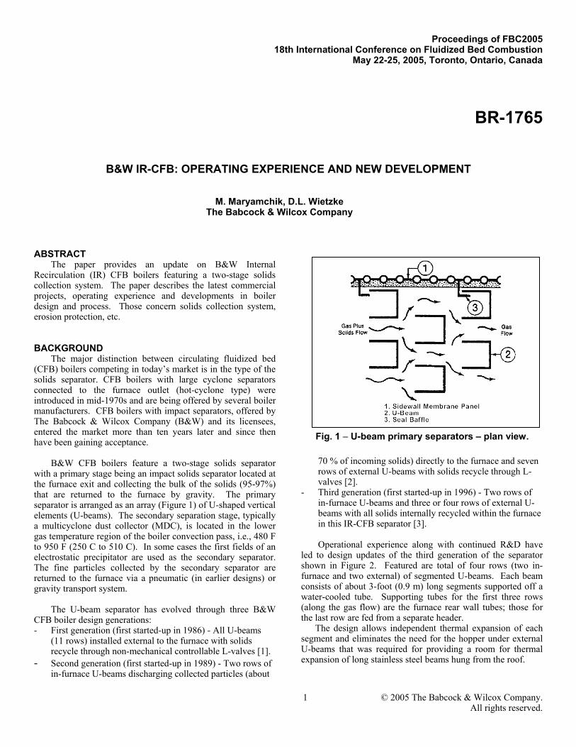
B&W CFB boilers feature a two-stage solids separator
with a primary stage being an impact solids separator located at the furnace exit and collecting the bulk of the solids (95-97%) that are returned to the furnace by gravity. The primary separator is arranged as an array (Figure 1) of U-shaped vertical elements (U-beams). The secondary separation stage, typically a multicyclone dust collector (MDC), is located in the lower gas temperature region of the boiler convection pass, i.e., 480 F to 950 F (250 C to 510 C). In some cases the first fields of an electrostatic precipitator are used as the secondary separator. The fine particles collected by the secondary separator are returned to the furnace via a pneumatic (in earlier designs) or gravity transport system.
The U-beam separator has evolved through three B&W
CFB boiler design generations: - First generation (first started-up in 1986) - All U-beams
(11 rows) installed external to the furnace with solids recycle through non-mechanical controllable L-valves [1].
- Second generation (first started-up in 1989) - Two rows of in-furnace U-beams discharging collected particles (about
70 % of incoming solids) directly to the furnace and seven rows of external U-beams with solids recycle through L-valves [2].
- Third generation (first started-up in 1996) - Two rows of in-furnace U-beams and three or four rows of external U-beams with all solids internally recycled within the furnace in this IR-CFB separator [3]. Operational experience along with continued R&D have
led to design updates of the third generation of the separator shown in Figure 2. Featured are total of four rows (two in-furnace and two external) of segmented U-beams. Each beam consists of about 3-foot (0.9 m) long segments supported off a water-cooled tube. Supporting tubes for the first three rows (along the gas flow) are the furnace rear wall tubes; those for the last row are fed from a separate header. The design allows independent thermal expansion of each segment and eliminates the need for the hopper under external U-beams that was required for providing a room for thermal expansion of long stainless steel beams hung from the roof.
Fig. 1 – U-beam primary separators – plan view.

2 © 2005 The Babcock & Wilcox Company. All rights reserved.
As a result, dramatic simplification and cost reduction of the U-beam separator have been achieved.
Over the same period, the design of the MDC separator has been improved for better efficiency, reliability and maintainability. The current design (Figure 3) has a top gas inlet and a side gas outlet. The cyclone elements have 9 in. (229 mm) diameter regardless of the boiler capacity. The MDC solids recycle system has evolved from a dense-phase pneumatic transport (first generation) to a dilute-phase pneumatic transport (second generation) to gravity conveying (third generation).
The latest MDC separator improvement has to do with the
cyclone elements material. The cyclone sleeves and spin vanes were made of high hardness (550 BHN) cast iron providing their reliable operation but associated with certain maintenance expenses. Replacing cast iron material with ceramics of the same element configuration resulted in drastic reduction of wear and corresponding need in the elements replacement (see more below in “MDC experience”).
The second-generation CFB boiler at Ebensburg,
Pennsylvania, in a cogeneration plant commissioned in early 1991, exemplifies the long-term boiler performance. This
boiler (Figure 4) burns high-ash (average 45% ash) Western Pennsylvania waste bituminous coal.
The unit was designed for 55 MWe capacity (465 klb/hr or
211 t/hr steam flow), but was uprated in 1995 and again in 1997 and since then has been operated at 10% overload. Boiler performance and availability are shown in Table 1 and Figure 5, respectively. The Ebensburg plant has received the Association of Independent Power Producers of Pennsylvania (ARIPPA) award for the highest availability among plants firing coal mine waste fuels.
The CFB boiler at Southern Illinois University (SIU) in Carbondale, Illinois, represents the third generation design.
In-FurnaceU-Beams
ExternalU-Beams
GasFlow
Furnace
GasFlow
GasPlusSolidsFlow
Fig. 2 – IR-CFB primary particles collectionsystem.
Fig. 3 – Multicyclone dust collector.
Fig. 4 – Ebensburg CFB boiler.

3 © 2005 The Babcock & Wilcox Company. All rights reserved.
Fig. 5 – Ebensburg plant availability.
Table 1Ebensburg Operating Data
Operating Steam Flow, t/hr (klb/hr) 234 (516) Steam Flow @ MCR, t/hr (klb/hr) 211 (465) Steam Temperature, C (F) 512 (953) Steam Pressure, MPa (psig) 10.6 (1540) SH Steam Temperature Control Range, % 30-110 Load Turndown Ratio without Auxiliary Fuel 5:1 Emissions NOx, ppm (lb/106 Btu) <100 (<0.14) SO2, ppm (lb/106 Btu) <300 (<0.60) CO, ppm (lb/106 Btu) <230 (<0.20) Ca/S Molar Ratio 2.1-2.4
Fig. 6 – Southern Illinois University IR-CFB boiler.

4 © 2005 The Babcock & Wilcox Company. All rights reserved.
The boiler (Figure 6) was designed for 35 MWt output for cogeneration application, utilizing high-sulfur Illinois bituminous coal. Boiler performance and availability are shown in Table 2 and Figure 7, respectively. The third generation design was also used for the Kanoria Chemical project in India (as well as for the second Kanoria CFB project recently awarded to Thermax Babcock & Wilcox, B&W’s CFB licensee in India), two boilers for Konya Sugar in Turkey, being erected by Gama, B&W’s CFB licensee in Turkey, and some others.
Operating experience of B&W coal-fired CFB boilers has
clearly confirmed their efficient performance and high reliability.
DESIGN FEATURES The design of a solids separator is the core of a CFB
combustion technology since it has major impact on the boiler layout, cost, fuel and sorbent utilization, operational flexibility and reliability.
Table 2 SIU Operating Data
Steam Flow @ MCR, t/hr (klb/hr) 46 (101.5) Steam Temperature, C (F) 399 (750) Steam Pressure, MPa (psig) 4.4 (640) SH Steam Temperature Control Range, % 40-110 Load Turndown Ratio without Auxiliary Fuel 5:1 Emissions NOx, ppm (lb/106 Btu) <100 (<0.14) SO2, % removal 90 CO, ppm (lb/106 Btu) <200 (<0.17) Ca/S Molar Ratio 2.3
Fig. 7 – SIU plant availability.

5 © 2005 The Babcock & Wilcox Company. All rights reserved.
In all these aspects B&W’s CFB boilers with the two-stage solids separation provide the following design features:
a) High solids collection efficiency
The collection efficiency of the two-stage solids separator is intrinsically high due to the greater efficiency of the MDC internal collection elements. Higher solids collection efficiency helps to achieve greater inventory of fine circulating particles in the furnace that provides: a) higher furnace heat transfer rate, b) ability to better control furnace temperature, and c) better carbon and sorbent utilization due to the increased residence time of fine particles.
b) Controlled furnace temperature
The furnace temperature is controlled in response to load changes and variations of fuel and/or sorbent properties by controlling the solids recycle rate from the MDC. The recycle rate at high boiler loads is set to achieve the upper furnace density required to maintain the target furnace temperature. At low loads, the recycle rate directly controls the dense bed temperature. The capacity of the MDC hoppers is used for solids transfer to and from the furnace. Excessive solids collected by the MDC are purged if needed. With B&W CFB boilers, the load can be reduced without auxiliary fuel to 20% of maximum continuous rating (MCR).
c) Low auxiliary power
The auxiliary power requirement is lower for impact-separator type boilers since the total pressure drop across the two-stage separator (U-beams + MDC) is only 4 in. wc (1 kPa). In addition, high-pressure air blowers for fluidization of returning solids are not needed.
d) Uniform gas flow
The gases exiting from the furnace to the U-beam separator across the furnace width provide for a uniform two-dimensional gas flow pattern. This allows placement of in-furnace surfaces as needed over the entire furnace height and width, including the region adjacent to the rear wall in the upper furnace. With proven reliability of in-furnace heating surfaces, this makes unnecessary the use of external heat exchangers and allows selection of the furnace height based on combustion/sulfur capture considerations rather than on a heating surface requirement. Combined with high collection efficiency of the two-stage solids separator, this allows reduced furnace height.
e) High solids separator reliability
U-beams and MDC have high reliability and low maintenance since they do not include any maintenance-intensive components such as refractory, loop-seals, expansion joints, vortex finders, etc. The U-beam design that has evolved through 18 years of operating experience has proven to be very reliable, requiring no maintenance. U-beam design criteria include conservative assumptions of 25 year life of U-beam materials and supports. The MDC internals made of cast iron require some maintenance during planned shutdowns, but this
expense has been minimal on the operating B&W CFB boilers and can now be reduced further with ceramic elements.
f) Integral design/small footprint
The U-beam separator is integral with the boiler enclosure providing for the most compact and cost-efficient boiler layout, similar to the conventional two-pass pulverized coal fired (PC) boiler. This feature is especially important for retrofitting outdated PC boilers with CFB technology in repowering applications where keeping the existing boiler “footprint” is highly desirable.
g) Minimal refractory use
The amount of refractory used in the B&W CFB boilers is 80-90% less than that used for similar capacity CFB boilers with non-cooled hot cyclones and 40-50% less than CFB boilers with cooled cyclones. For B&W CFB boilers the start-up time is not limited by the rate of temperature rise of refractory. h) Low maintenance
A distinct feature of IR-CFB is low maintenance. Among the factors contributing to this feature are: low overall amount of refractory, Reduced Diameter Zone (RDZ) design (see below), low furnace exit velocity, and absence of hot expansion joints.
TWO-STAGE SOLIDS SEPARATOR EXPERIENCE
Two key areas important for design evaluation of CFB boilers with impact separator are high reliability of the two-stage solids separator and its superior collection efficiency. The long term operating experience and test data provide the definite affirmation of the impact separator plus MDC design as described in the following section. Reliability U-beam experience. U-beams are conservatively designed to operate in the flue gas environment at the exit of the CFB furnace. B&W has selected U-beam materials – typically high nickel, high chromium, austenitic stainless steels – to resist erosion and corrosion while possessing adequate long term strength at the design temperatures. Substantial design margins are provided to accommodate possible U-beam temperature deviations from the expected value based on average gas temperature leaving the furnace. These margins eliminate the possibility of the U-beams being damaged during operational upsets.
Mechanical conditions of U-beams along with related
boiler thermal performance data have been monitored over the 13 years of operation at the Ebensburg CFB boiler. It was confirmed that erosion losses were negligible due to a tough, erosion resistant film formed on the surface of the U-beams. It was also determined that the material was resistant to corrosion and deformation when operated within the design margins.

6 © 2005 The Babcock & Wilcox Company. All rights reserved.
The Ebensburg CFB boiler capacity was increased by 10% over the original design. For evaluated economic reasons no other changes to the boiler were made to maintain the design temperature and excess air at the furnace exit. This resulted in more than 3 years of operation with local U-beams temperatures approaching or exceeding the design margins.
After this 3 year period of operation with excessively high
temperatures, signs of U-beam mechanical degradation have begun appearing where the maximum temperatures or maximum solids loading occur. Some U-beam channels began to flare, and the mid-section of several U-beams rotated up to 10 degrees from the original position. Also, several corrosion spots were found near the bottom of the rear-most rows of U-beams where U-beams were covered with ash deposits. Ebensburg has now introduced modifications that eliminate the high temperature at the 10%-uprated maximum load. The current design has been changed to avoid these degradations even during prolonged high temperature operation.
Regardless of some U-beam deformation observed as a
result of the off-design operating conditions, no deterioration of boiler performance was detected and no U-beams have had to be replaced. Maintenance work on U-beams has been minimal, consisting primarily of cleaning of solids accumulated on the top side of the alignment pans located near the bottom of U-beams and an occasional repair of the pan and strap attachment welds.
The latest U-beam design offers even higher reliability
since it employs the same high-quality materials while reducing the size of each supported element and the corresponding stress.
The resilience of U-beams to operating conditions
associated with excessive temperatures and increased gas velocities contrasts to that of vortex finders (a part of hot-cyclones) which are made of similar materials and exposed to a similar gas/solids environment. Vortex finder failures have been reported with a substantial detrimental effect on boiler performance and considerable maintenance cost
MDC experience. At Ebensburg, due to the waste coal's high ash content and ash abrasiveness, about 20% of the MDC internal elements made of high hardness cast iron were being replaced during each yearly outage to avoid a loss of MDC efficiency. At other B&W CFB boilers burning high-sulfur bituminous coal, circulating solids are typically less abrasive as compared to the Ebensburg unit, and the MDC internal elements have either not required replacement or have been replaced as needed during planned outages. For example, at SIU, firing medium-ash high-sulfur coal, the first replacement of about 20% of the MDC internals took place in the fifth year of operation.
Four years ago at Ebensburg, worn-out cast iron elements
started being replaced with the elements made of ceramics having the same design. During the last yearly outage no wear was found on any of the ceramic elements.
Maintenance work was needed on the Ebensburg pneumatic MDC solids recycle system which normally is done on line, or during planned boiler outages. At SIU, where air-slide ash conveyors were used, virtually no maintenance work was needed on the return system. This system has been further simplified for new offerings. Variable speed, inclined screw(s) are used at the MDC hopper discharge(s), in place of previously used rotary valves, to control the flow rate of recycled solids. The solids in the inclined screw provide the required pressure seal without the maintenance associated with the close tolerance, machined surfaces found in rotary valves.
RDZ experience. The patented Reduced Diameter Zone (RDZ) design (Figure 8) was introduced at Ebensburg in the year 2000. The RDZ consists of a reduced diameter tube section mating to a specially shaped ceramic tile. The reduced diameter tube section on each tube slopes away from the solids falling down the wall along the surface profile of the tube panel, thereby eliminating the discontinuity adjacent to the tube. RDZ installation at Ebensburg resulted in increasing time span between the outages from six months (dictated by refractory interface maintenance requirements) to a year or more.
Plant outage schedule is now determined primarily by
auxiliary equipment maintenance requirements. Due to lack of necessity, the plant also stopped renewing tube protective coating above the refractory interface, thus effectively eliminating maintenance of this furnace area.
Maintenance cost. The maintenance cost of the solids separators in the B&W CFB boilers is intrinsically low. At Ebensburg, the total maintenance cost for U-beams and L-valves over 10 years of operation was about $20,000. The average maintenance cost for the MDC with cast iron collection elements was about $25,000 per year, which was virtually eliminated with introduction of ceramic collection elements. There was no loss of power generation due to U-beam or L-
Fig. 8 – Reduced diameter zone.
Furnace Wall(inside)
Internal Evaporative
Panel
7 © 2005 The Babcock & Wilcox Company. All rights reserved.
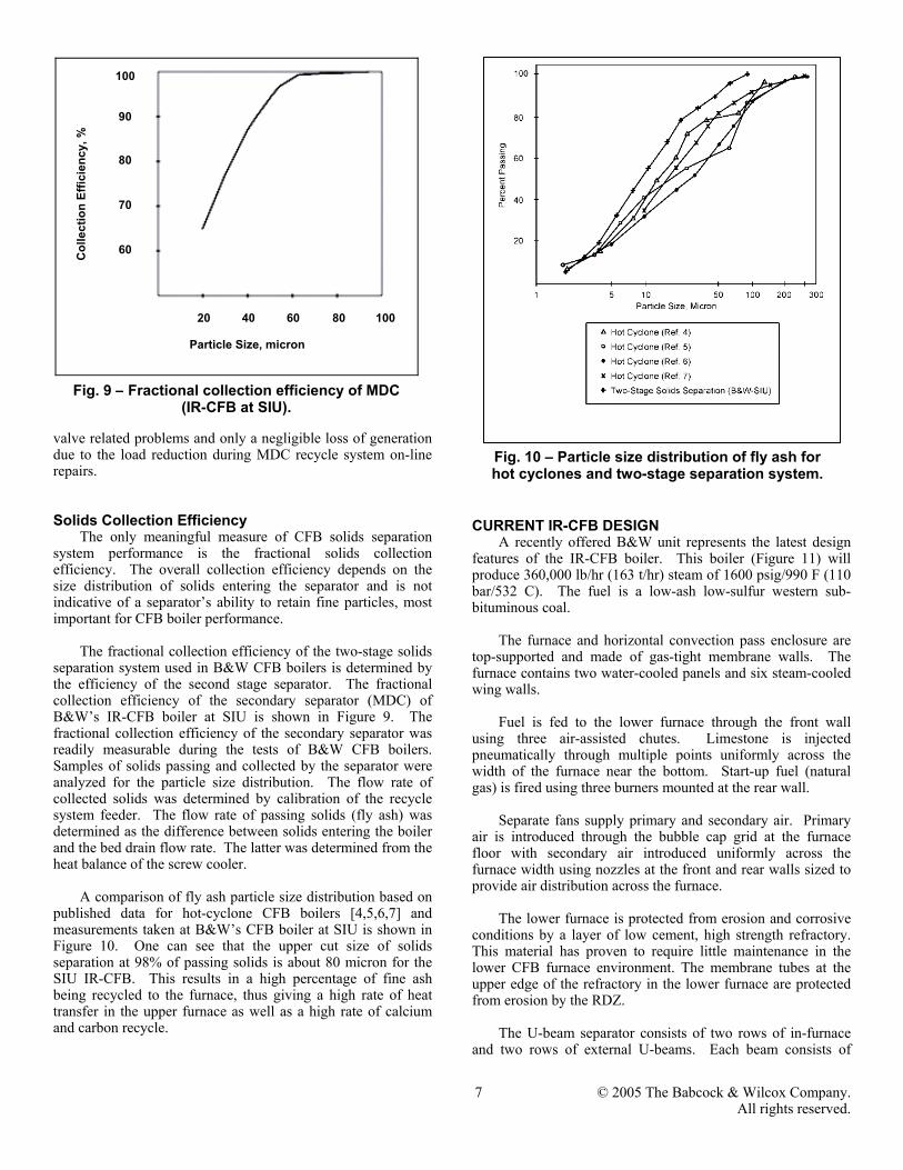
valve related problems and only a negligible loss of generation due to the load reduction during MDC recycle system on-line repairs. Solids Collection Efficiency
The only meaningful measure of CFB solids separation system performance is the fractional solids collection efficiency. The overall collection efficiency depends on the size distribution of solids entering the separator and is not indicative of a separator’s ability to retain fine particles, most important for CFB boiler performance.
The fractional collection efficiency of the two-stage solids
separation system used in B&W CFB boilers is determined by the efficiency of the second stage separator. The fractional collection efficiency of the secondary separator (MDC) of B&W’s IR-CFB boiler at SIU is shown in Figure 9. The fractional collection efficiency of the secondary separator was readily measurable during the tests of B&W CFB boilers. Samples of solids passing and collected by the separator were analyzed for the particle size distribution. The flow rate of collected solids was determined by calibration of the recycle system feeder. The flow rate of passing solids (fly ash) was determined as the difference between solids entering the boiler and the bed drain flow rate. The latter was determined from the heat balance of the screw cooler.
A comparison of fly ash particle size distribution based on
published data for hot-cyclone CFB boilers [4,5,6,7] and measurements taken at B&W’s CFB boiler at SIU is shown in Figure 10. One can see that the upper cut size of solids separation at 98% of passing solids is about 80 micron for the SIU IR-CFB. This results in a high percentage of fine ash being recycled to the furnace, thus giving a high rate of heat transfer in the upper furnace as well as a high rate of calcium and carbon recycle.
CURRENT IR-CFB DESIGN
A recently offered B&W unit represents the latest design features of the IR-CFB boiler. This boiler (Figure 11) will produce 360,000 lb/hr (163 t/hr) steam of 1600 psig/990 F (110 bar/532 C). The fuel is a low-ash low-sulfur western sub-bituminous coal.
The furnace and horizontal convection pass enclosure are
top-supported and made of gas-tight membrane walls. The furnace contains two water-cooled panels and six steam-cooled wing walls.
Fuel is fed to the lower furnace through the front wall
using three air-assisted chutes. Limestone is injected pneumatically through multiple points uniformly across the width of the furnace near the bottom. Start-up fuel (natural gas) is fired using three burners mounted at the rear wall.
Separate fans supply primary and secondary air. Primary
air is introduced through the bubble cap grid at the furnace floor with secondary air introduced uniformly across the furnace width using nozzles at the front and rear walls sized to provide air distribution across the furnace.
The lower furnace is protected from erosion and corrosive
conditions by a layer of low cement, high strength refractory. This material has proven to require little maintenance in the lower CFB furnace environment. The membrane tubes at the upper edge of the refractory in the lower furnace are protected from erosion by the RDZ.
The U-beam separator consists of two rows of in-furnace
and two rows of external U-beams. Each beam consists of
Fig. 9 – Fractional collection efficiency of MDC (IR-CFB at SIU).
Fig. 10 – Particle size distribution of fly ash for hot cyclones and two-stage separation system.
C
olle
ctio
n Ef
ficie
ncy,
%
Particle Size, micron
100
90
80
70
60
20 40 60 80 100

8 © 2005 The Babcock & Wilcox Company. All rights reserved.
about 3-foot (0.9 m) long segments supported off a water-cooled tube. Supporting tubes for the first three rows (along the gas flow) are the tubes of the furnace rear wall; those for the last row are fed from a separate header. The U-beam segments are made of SA240TP309H material, which was also used in previous B&W CFB projects.
Pendant superheater banks are located downstream of the
U-beams in the horizontal convection pass. Steam from the drum flows through the side walls of the pendant superheater enclosure, then through the primary superheater bank followed by the wing walls and the secondary superheater bank to the main steam outlet.
The MDC is located immediately downstream of the
horizontal convection pass. Further in the gas path it is followed by the economizer and tubular air heater (air inside tubes). The air heater is side-split for the primary and secondary air. After the air heater, gas flows through a baghouse and an induced draft (ID) fan to a stack.
Solids collected by the MDC are recycled back to the
furnace through six recycle lines utilizing inclined screw conveyors and gravity feed.
IR-CFB scale-up
With the current design approach, IR-CFB boilers with a design similar to that described above are offered for capacities up to 200 MWe (600 MWth).
CONCLUSIONS Lessons learned from 18 years of B&W’s CFB technology
application have led to development of the reliable, low-cost IR-CFB boiler design. Long-term operating experience of the
distinct two-stage solids separator has proven its high reliability and superior collection efficiency. The main advantages of this boiler design are higher furnace heat transfer rate, ability to better control furnace temperature, and increased residence time of fine carbon and sorbent particles. Its operators take advantage of the lower maintenance costs and auxiliary power requirements. The IR-CFB boiler achieves the required performance with reduced furnace height and smaller boiler footprint. This design is especially attractive for replacing existing obsolete PC boilers in the same space.
REFERENCES [1] F. Belin, et al., “Waste Wood Combustion in Circulating Fluidized Bed Boilers,” Proceedings of the Second International Conference in Circulating Fluidized Beds, 1988. [2] C. E. Price and D. J. Walker, “Coal and Waste Coal-Fired Boilers Accumulate Operating Experience,” Proceedings of 12th International Conference on Fluidized-Bed Combustion, 1993. [3] Belin, et al., “Update of Operating Experience of B&W IR-CFB Coal-Fired Boilers,” Proceedings of 15th International Conference on Fluidized-Bed Combustion, 1999.
[4] D. R. Hajicek et al., “The Impact of Coal Quality on Circulating Fluidized Bed Combustor Performance,” EPRI Coal Quality Conference, 1992.
[5] W. vom Berg and K.-H. Puch, “Verwertung von Ruckstanden aus Wirbelschichtfeuerungsanlagen,” Vortrage VGB – Konferenz, “Wirbelschihtsysteme 1992.”
[6] M. Gierse, “Aspects of the Performance of Three Different Types of Industrial Fluidized Bed Boilers,” Proceedings of the 3rd International Conference on Circulating Fluidized Beds, 1990.
[7] U. Muschelknautz and E. Muschelknautz, “Improvements of Cyclones in CFB Power Plants and Quantitative Estimation on Their Effects on the Boiler Solids Inventory,” Proceedings of the 6th International Conference on Circulating Fluidized Beds, 1999.
Disclaimer Although the information presented in this work is believed
to be reliable, this work is published with the understanding that The Babcock & Wilcox Company and the authors are supplying general information and are not attempting to render or provide engineering or professional services. Neither The Babcock & Wilcox Company nor any of its employees make any warranty, guarantee, or representation, whether expressed or implied, with respect to the accuracy, completeness or usefulness of any information, product, process or apparatus discussed in this work; and neither The Babcock & Wilcox Company nor any of its employees shall be liable for any losses or damages with respect to or resulting from the use of, or the inability to use, any information, product, process or apparatus discussed in this work.
Fig. 11 – Current IR-CFB design.