Embed Size (px)
Citation preview
7/14/2019 Bvpe30mmi - Copy
http://slidepdf.com/reader/full/bvpe30mmi-copy 1/136
COLOR VIDEO CAMERA
BVP-E30BVP-E30PBVP-E30WS
BVP-E30WSP
MAINTENANCE MANUALVolume 1 1st Edition (Revised 1)Serial No. 100001 and Higher: BVP-E30Serial No. 400001 and Higher: BVP-E30PSerial No. 100001 and Higher: BVP-E30WSSerial No. 400001 and Higher: BVP-E30WSP
7/14/2019 Bvpe30mmi - Copy
http://slidepdf.com/reader/full/bvpe30mmi-copy 2/136
BVP-E30/E30P M-V1
! WARNINGThis manual is intended for qualified service personnel only.
To reduce the r isk of electric shock, fire or injury, do not perform any servicing other than that
contained in the operating instructions unless you are qualified to do so. Refer all servicing to
qualified service personnel.
! WARNUNGDie Anleitung ist nur für qualifiziertes Fachpersonal bestimmt.
Alle Wartungsarbeiten dürfen nur von qualifiziertem Fachpersonal ausgeführt werden. Um die
Gefahr eines elektrischen Schlages, Feuergefahr und Verletzungen zu vermeiden, sind bei
Wartungsarbeiten strikt die Angaben in der Anleitung zu befolgen. Andere als die angegebenWartungsarbeiten dürfen nur von Personen ausgeführt werden, die eine spezielle Befähigung
dazu besitzen.
! AVERTISSEMENTCe manual est destiné uniquement aux personnes compétentes en charge de l’entretien. Afin
de réduire les risques de décharge électrique, d’incendie ou de blessure n’effectuer que les
réparations indiquées dans le mode d’emploi à moins d’être qualifié pour en effectuer d’autres.
Pour toute réparation faire appel à une personne compétente uniquement.
Voor de klanten in Nederland
Gooi de batterij niet weg maar lever deze in als klein
chemisch afval (KCA).
For the customers in Taiwan only
Für Kunden in Deutschland
Entsorgungshinweis: Bitte werfen Sie nur entladene
Batterien in die Sammelboxen beim Handel oder den
Kommunen. Entladen sind Batterien in der Regel dann,
wenn das Gerät abschaltet und signalisiert “Batterie
leer” oder nach längerer Gebrauchsdauer der Batterien
“nicht mehr einwandfrei funktioniert”. Um
sicherzugehen, kleben Sie die Batteriepole z.B. mit
einem Klebestreifen ab oder geben Sie die Batterieneinzeln in einen Plastikbeutel.
7/14/2019 Bvpe30mmi - Copy
http://slidepdf.com/reader/full/bvpe30mmi-copy 3/136
BVP-E30/E30P M-V1
Vorsicht!
Explosionsgefahr bei unsachgemäßem Austauschder Batterie.
Ersatz nur durch denselben oder einen vomHersteller empfohlenen ähnlichen Typ. Entsorgung
gebrauchter Batterien nach Angaben desHerstellers.
ATTENTION
Il y a danger d’explosion s’il y a remplacementincorrect de la batterie.
Remplacer uniquement avec une batterie du mêmetype ou d’un type équivalent recommandé par le
constructeur.Mettre au rebut les batteries usagées conformément
aux instructions du fabricant.
ADVARSEL!
Lithiumbatteri-Eksplosionsfare ved fejlagtighåndtering.
Udskiftning må kun ske med batteriaf samme fabrikat og type.
Levér det brugte batteri tilbage til leverandøren.
ADVARSEL
Lithiumbatteri - Eksplosjonsfare.Ved utskifting benyttes kun batteri som
anbefalt av apparatfabrikanten.Brukt batteri returneresapparatleverandøren.
VARNING
Explosionsfara vid felaktigt batteribyte.Använd samma batterityp eller en likvärdig typsom rekommenderas av apparattillverkaren.
Kassera använt batteri enligt gällandeföreskrifter.
VAROITUS
Paristo voi räjähtää jos se on virheellisestiasennettu.
Vaihda paristo ainoastaan laitevalmistajansuosittelemaan tyyppiin.
Hävitä käytetty paristo valmistajan ohjeidenmukaisesti.
CAUTION
Danger of explosion if battery is incorrectly replaced.
Replace only with the same or equivalent typerecommended by the manufacturer.Dispose of used batteries according to themanufacturer’s instructions.
1 (P)

7/14/2019 Bvpe30mmi - Copy
http://slidepdf.com/reader/full/bvpe30mmi-copy 4/136
7/14/2019 Bvpe30mmi - Copy
http://slidepdf.com/reader/full/bvpe30mmi-copy 5/136
BVP-E30/E30P M-V1 1 (E)
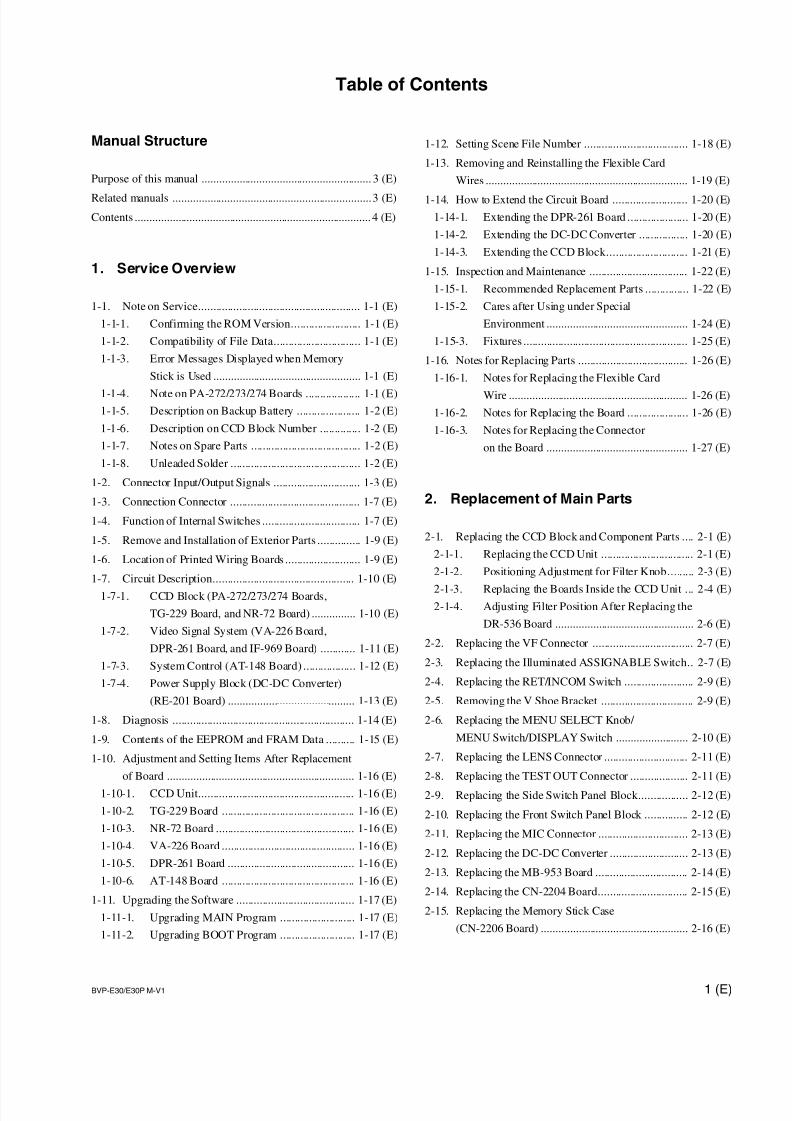
Table of Contents
Manual Structure
Purpose of this manual ........................................................... 3 (E)
Related manuals .....................................................................3 (E)
Contents .................................................................................. 4 (E)
1. Service Overview
1-1. Note on Service........................................................ 1-1 (E)
1-1-1. Confirming the ROM Version........................ 1-1 (E)
1-1-2. Compatibility of File Data.............................. 1-1 (E)
1-1-3. Error Messages Displayed when Memory
Stick is Used ................................................... 1-1 (E)
1-1-4. Note on PA-272/273/274 Boards ................... 1-1 (E)
1-1-5. Description on Backup Battery ...................... 1-2 (E)
1-1-6. Description on CCD Block Number .............. 1-2 (E)
1-1-7. Notes on Spare Parts ...................................... 1-2 (E)
1-1-8. Unleaded Solder ............................................. 1-2 (E)
1-2. Connector Input/Output Signals .............................. 1-3 (E)
1-3. Connection Connector ............................................. 1-7 (E)
1-4. Function of Internal Switches .................................. 1-7 (E)
1-5. Remove and Installation of Exterior Parts ............... 1-9 (E)
1-6. Location of Printed Wiring Boards .......................... 1-9 (E)
1-7. Circuit Description................................................. 1-10 (E)
1-7-1. CCD Block (PA-272/273/274 Boards,
TG-229 Board, and NR-72 Board) ............... 1-10 (E)
1-7-2. Video Signal System (VA-226 Board,
DPR-261 Board, and IF-969 Board) ............ 1-11 (E)
1-7-3. System Control (AT-148 Board) .................. 1-12 (E)
1-7-4. Power Supply Block (DC-DC Converter)
(RE-201 Board) ............................................ 1-13 (E)
1-8. Diagnosis ............................................................... 1-14 (E)
1-9. Contents of the EEPROM and FRAM Data .......... 1-15 (E)
1-10. Adjustment and Setting Items After Replacement
of Board ................................................................. 1-16 (E)
1-10-1. CCD Unit...................................................... 1-16 (E)
1-10-2. TG-229 Board .............................................. 1-16 (E)
1-10-3. NR-72 Board ................................................ 1-16 (E)
1-10-4. VA-226 Board .............................................. 1-16 (E)
1-10-5. DPR-261 Board ............................................ 1-16 (E)
1-10-6. AT-148 Board .............................................. 1-16 (E)
1-11. Upgrading the Software ......................................... 1-17 (E)
1-11-1. Upgrading MAIN Program .......................... 1-17 (E)
1-11-2. Upgrading BOOT Program .......................... 1-17 (E)
1-12. Setting Scene File Number .................................... 1-18 (E)
1-13. Removing and Reinstalling the Flexible Card
Wires ...................................................................... 1-19 (E)
1-14. How to Extend the Circuit Board .......................... 1-20 (E)
1-14-1. Extending the DPR-261 Board ..................... 1-20 (E)
1-14-2. Extending the DC-DC Converter ................. 1-20 (E)
1-14-3. Extending the CCD Block............................ 1-21 (E)
1-15. Inspection and Maintenance .................................. 1-22 (E)
1-15-1. Recommended Replacement Parts ............... 1-22 (E)
1-15-2. Cares after Using under Special
Environment ................................................. 1-24 (E)
1-15-3. Fixtures ......................................................... 1-25 (E)
1-16. Notes for Replacing Parts ...................................... 1-26 (E)
1-16-1. Notes for Replacing the Flexible Card
Wire .............................................................. 1-26 (E)
1-16-2. Notes for Replacing the Board ..................... 1-26 (E)
1-16-3. Notes for Replacing the Connector
on the Board ................................................. 1-27 (E)
2. Replacement of Main Parts
2-1. Replacing the CCD Block and Component Parts .... 2-1 (E)
2-1-1. Replacing the CCD Unit ................................ 2-1 (E)
2-1-2. Positioning Adjustment for Filter Knob......... 2-3 (E)
2-1-3. Replacing the Boards Inside the CCD Unit ... 2-4 (E)2-1-4. Adjusting Filter Position After Replacing the
DR-536 Board ................................................ 2-6 (E)
2-2. Replacing the VF Connector ................................... 2-7 (E)
2-3. Replacing the Illuminated ASSIGNABLE Switch.. 2-7 (E)
2-4. Replacing the RET/INCOM Switch ........................ 2-9 (E)
2-5. Removing the V Shoe Bracket ................................ 2-9 (E)
2-6. Replacing the MENU SELECT Knob/
MENU Switch/DISPLAY Switch ......................... 2-10 (E)
2-7. Replacing the LENS Connector ............................. 2-11 (E)
2-8. Replacing the TEST OUT Connector .................... 2-11 (E)
2-9. Replacing the Side Switch Panel Block................. 2-12 (E)
2-10. Replacing the Front Switch Panel Block ............... 2-12 (E)
2-11. Replacing the MIC Connector ............................... 2-13 (E)
2-12. Replacing the DC-DC Converter ........................... 2-13 (E)
2-13. Replacing the MB-953 Board ................................ 2-14 (E)
2-14. Replacing the CN-2204 Board............................... 2-15 (E)
2-15. Replacing the Memory Stick Case
(CN-2206 Board) ................................................... 2-16 (E)
7/14/2019 Bvpe30mmi - Copy
http://slidepdf.com/reader/full/bvpe30mmi-copy 6/136
BVP-E30/E30P M-V12 (E)
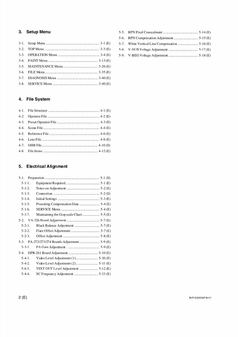
3. Setup Menu
3-1. Setup Menu .............................................................. 3-1 (E)
3-2. TOP Menu ............................................................... 3-3 (E)
3-3. OPERATION Menu ................................................ 3-4 (E)
3-4. PAINT Menu ......................................................... 3-13 (E)
3-5. MAINTENANCE Menu........................................ 3-26 (E)
3-6. FILE Menu............................................................. 3-35 (E)
3-7. DIAGNOSIS Menu ............................................... 3-40 (E)
3-8. SERVICE Menu .................................................... 3-40 (E)
4. File System
4-1. File Structure ........................................................... 4-1 (E)
4-2. Operator File ............................................................ 4-2 (E)4-3. Preset Operator File ................................................. 4-3 (E)
4-4. Scene File................................................................. 4-4 (E)
4-5. Reference File .......................................................... 4-6 (E)
4-6. Lens File .................................................................. 4-8 (E)
4-7. OHB File ................................................................ 4-10 (E)
4-8. File Items ............................................................... 4-12 (E)
5. Electrical Alignment
5-1. Preparation ............................................................... 5-1 (E)
5-1-1. Equipment Required....................................... 5-1 (E)
5-1-2. Notes on Adjustment ...................................... 5-2 (E)
5-1-3. Connection ..................................................... 5-2 (E)
5-1-4. Initial Settings ................................................ 5-3 (E)
5-1-5. Presetting Compensation Data ....................... 5-4 (E)
5-1-6. SERVICE Menu ............................................. 5-4 (E)
5-1-7. Maintaining the Grayscale Chart.................... 5-5 (E)
5-2. VA-226 Board Adjustment ...................................... 5-7 (E)
5-2-1. Black Balance Adjustment ............................. 5-7 (E)
5-2-2. Flare Offset Adjustment ................................. 5-7 (E)
5-2-3. Offset Adjustment .......................................... 5-8 (E)
5-3. PA-272/273/274 Boards Adjustment ....................... 5-9 (E)
5-3-1. PA Gain Adjustment ...................................... 5-9 (E)
5-4. DPR-261 Board Adjustment .................................. 5-10 (E)
5-4-1. Video Level Adjustment (1)......................... 5-10 (E)
5-4-2. Video Level Adjustment (2)......................... 5-11 (E)
5-4-3. TEST OUT Level Adjustment ..................... 5-12 (E)
5-4-4. SC Frequency Adjustment ........................... 5-13 (E)
5-5. RPN Pixel Concealment ........................................ 5-14 (E)
5-6. RPN Compensation Adjustment ............................ 5-15 (E)
5-7. White Vertical Line Compensation ....................... 5-16 (E)
5-8. V-SUB Voltage Adjustment .................................. 5-17 (E)
5-9. V-REG Voltage Adjustment .................................. 5-18 (E)

7/14/2019 Bvpe30mmi - Copy
http://slidepdf.com/reader/full/bvpe30mmi-copy 7/136
3 (E)BVP-E30/E30P M-V1
Manual Structure
Purpose of this manual
This manual is the maintenance manual volume 1 of Color Video Camera BVP-E30/
E30P/E30WS/E30WSP.
This manual is intended for use by trained system and service engineers, and isprovided information that is premised parts levels service for this unit.
Related manuals
Besides this maintenance manual volume 1, the following manuals are available.
..... Operation Manual (Supplied with this unit)
This manual is necessary for the use and the operation of this unit.
Part No.: 3-854-245-XX
..... CD-ROM Manual (Supplied with this unit)This manual contains the operation manual of BVP-E30/E30WS, the operation
manual of each peripheral equipment included in BVP-E30 series, and the mainte-
nance manual of partial equipment (camera adaptor and the like).
Part No.: 3-854-379-XX
..... Maintenance Manual Volume 2 (Available on request)
This manual is provided information that is premised the parts level service
(exploded views, block diagrams, board layouts, schematic diagrams, detailed
parts lists and the like.) for this unit.
If this manual is required, please contact to your local Sony Sales Office/Service
Center.Part No.: 9-968-050-XX
..... “Semiconductor Pin Assignments” CD-ROM (Available on request)
This “Semiconductor Pin Assignments” CD-ROM allows you to search for
semiconductors used in Communication B&P Company equipment.
Semiconductors that cannot be searched for on this CD-ROM are listed in the
maintenance manual for the corresponding unit. The maintenance manual contains
a complete list of all semiconductors and their ID Nos., and thus should be used
together with the CD-ROM.
Part number: 9-968-546-06
7/14/2019 Bvpe30mmi - Copy
http://slidepdf.com/reader/full/bvpe30mmi-copy 8/136
4 (E) BVP-E30/E30P M-V1
Contents
The following is a summary of the sections of this manual.
Section 1 Service Overview
Describes the location of major parts, on-board, switches, tools, fixtures, adjust-
ments/setup after board replace, etc.
Section 2 Parts Replacement
Describes the replacement procedure of circuit board, CCD unit, connectors,
switches and others.
Section 3 Setup Menu
Describes the setup menu, etc.
Section 4 File System
Describes the file structure, etc.
Section 5 Electrical Alignment
Describes electrical adjustment necessary for maintenance of the unit or replacement
of parts.
7/14/2019 Bvpe30mmi - Copy
http://slidepdf.com/reader/full/bvpe30mmi-copy 9/136
1-1 (E)BVP-E30/E30P M-V1
Section 1
Service Overview
1-1. Note on Service
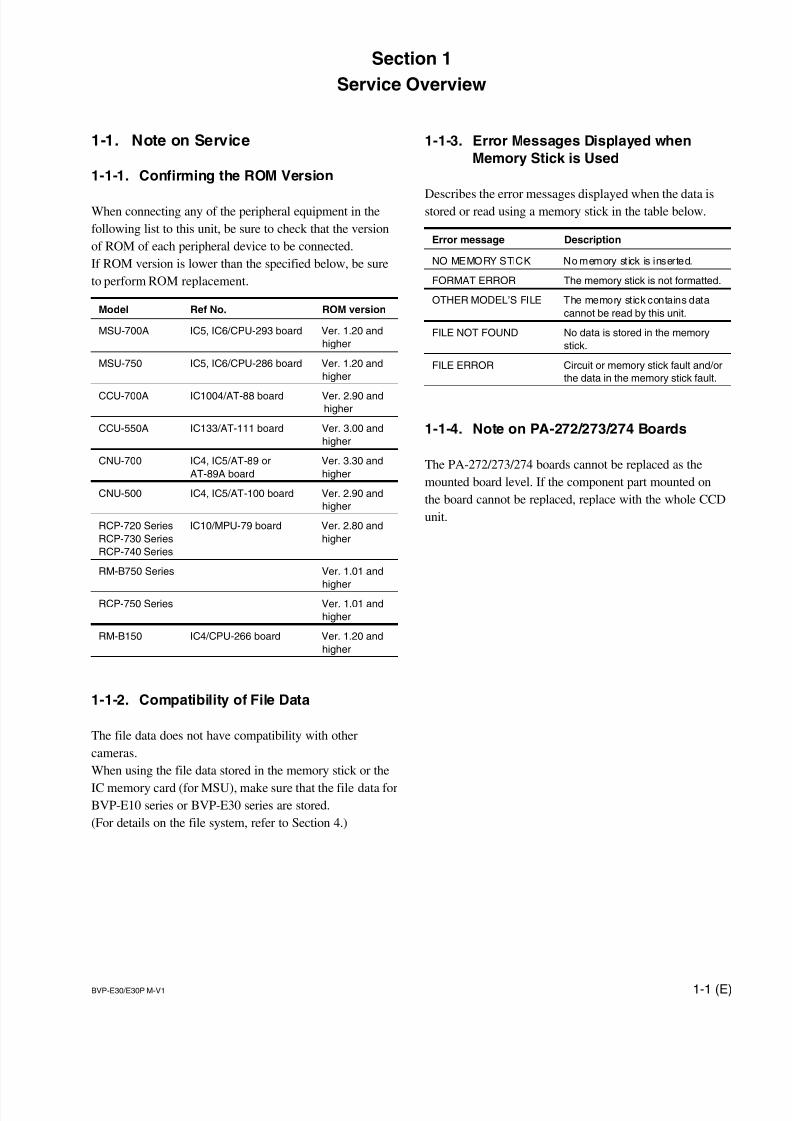
1-1-1. Confirming the ROM Version
When connecting any of the peripheral equipment in the
following list to this unit, be sure to check that the version
of ROM of each peripheral device to be connected.
If ROM version is lower than the specified below, be sure
to perform ROM replacement.
Model Ref No. ROM version
MSU-700A IC5, IC6/CPU-293 board Ver. 1.20 and
higher
MSU-750 IC5, IC6/CPU-286 board Ver. 1.20 and
higher
CCU-700A IC1004/AT-88 board Ver. 2.90 andhigher
CCU-550A IC133/AT-111 board Ver. 3.00 and
higher
CNU-700 IC4, IC5/AT-89 or Ver. 3.30 and
AT-89A board higher
CNU-500 IC4, IC5/AT-100 board Ver. 2.90 and
higher
RCP-720 Series IC10/MPU-79 board Ver. 2.80 and
RCP-730 Series higher
RCP-740 Series
RM-B750 Series Ver. 1.01 and
higherRCP-750 Series Ver. 1.01 and
higher
RM-B150 IC4/CPU-266 board Ver. 1.20 and
higher
1-1-2. Compatibility of File Data
The file data does not have compatibility with other
cameras.
When using the file data stored in the memory stick or the
IC memory card (for MSU), make sure that the file data forBVP-E10 series or BVP-E30 series are stored.
(For details on the file system, refer to Section 4.)
1-1-3. Error Messages Displayed when
Memory Stick is Used
Describes the error messages displayed when the data isstored or read using a memory stick in the table below.
Error message Description
NO MEMORY STICK No memory st ick is inserted.
FORMAT ERROR The memory stick is not formatted.
OTHER MODEL’S FILE The memory stick contains data
cannot be read by this unit.
FILE NOT FOUND No data is stored in the memory
stick.
FILE ERROR Circuit or memory stick fault and/or
the data in the memory stick fault.
1-1-4. Note on PA-272/273/274 Boards
The PA-272/273/274 boards cannot be replaced as the
mounted board level. If the component part mounted on
the board cannot be replaced, replace with the whole CCD
unit.
7/14/2019 Bvpe30mmi - Copy
http://slidepdf.com/reader/full/bvpe30mmi-copy 10/136
1-2 (E) BVP-E30/E30P M-V1
1-1-5. Description on Backup Battery
wThe lithium battery is critical part to safe operation.
Replace the component with Sony part whose part number
appears in the manual published by Sony.If the component is replaced by any part other than the
specified ones, this may cause a fire or electric shock.
cWhen replacing the lithium battery, ensure that the battery
is installed with + and _ poles connected to the correct
terminals. An inconnect connection may cause an explo-
sion or leakage of fluid result in physical damage in the
surrounding materials.
A lithium battery on the AT-148 board is used to back up
the date data to be stored in the memory stick. Reset the
date data using the DATE/TIME page (Refer to Section
3-5) in the MAINTENANCE menu after replacing the
dead battery.
Replacement part : BT1 (AT-148 board)
Description : CR-2032
(Lithium battery)
Parts number : ! 1-528-174-31
Recommended replacement period : Every 7 years
m. When replacing the AT-148 board, it is recommended to
replacing the battery at the same time.
. Resetting the date data is required even when the battery
is disconnected from the battery holder.
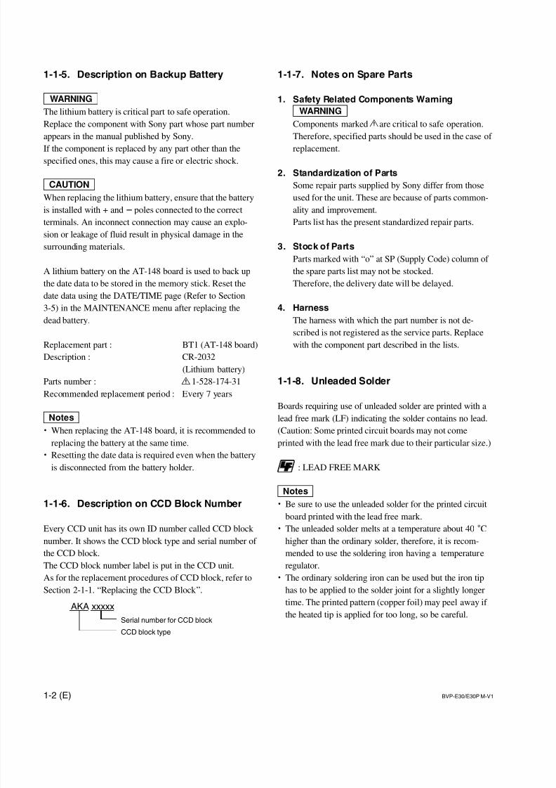
1-1-6. Description on CCD Block Number
Every CCD unit has its own ID number called CCD block
number. It shows the CCD block type and serial number of
the CCD block.The CCD block number label is put in the CCD unit.
As for the replacement procedures of CCD block, refer to
Section 2-1-1. “Replacing the CCD Block ”.
1-1-7. Notes on Spare Parts
1. Safety Related Components Warning
wComponents marked ! are critical to safe operation.
Therefore, specified parts should be used in the case of replacement.
2. Standardization of Parts
Some repair parts supplied by Sony differ from those
used for the unit. These are because of parts common-
ality and improvement.
Parts list has the present standardized repair parts.
3. Stock of Parts
Parts marked with “o” at SP (Supply Code) column of
the spare parts list may not be stocked.
Therefore, the delivery date will be delayed.
4. Harness
The harness with which the part number is not de-
scribed is not registered as the service parts. Replace
with the component part described in the lists.
1-1-8. Unleaded Solder
Boards requiring use of unleaded solder are printed with a
lead free mark (LF) indicating the solder contains no lead.
(Caution: Some printed circuit boards may not come
printed with the lead free mark due to their particular size.)
: LEAD FREE MARK
m. Be sure to use the unleaded solder for the printed circuit
board printed with the lead free mark.
. The unleaded solder melts at a temperature about 40 dChigher than the ordinary solder, therefore, it is recom-
mended to use the soldering iron having a temperatureregulator.
. The ordinary soldering iron can be used but the iron tip
has to be applied to the solder joint for a slightly longer
time. The printed pattern (copper foil) may peel away if
the heated tip is applied for too long, so be careful.AKA xxxxx
Serial number for CCD block
CCD block type
7/14/2019 Bvpe30mmi - Copy
http://slidepdf.com/reader/full/bvpe30mmi-copy 11/136
1-3 (E)BVP-E30/E30P M-V1
(EXTERNAL VIEW)
(EXTERNAL VIEW)
(EXTERNAL VIEW)
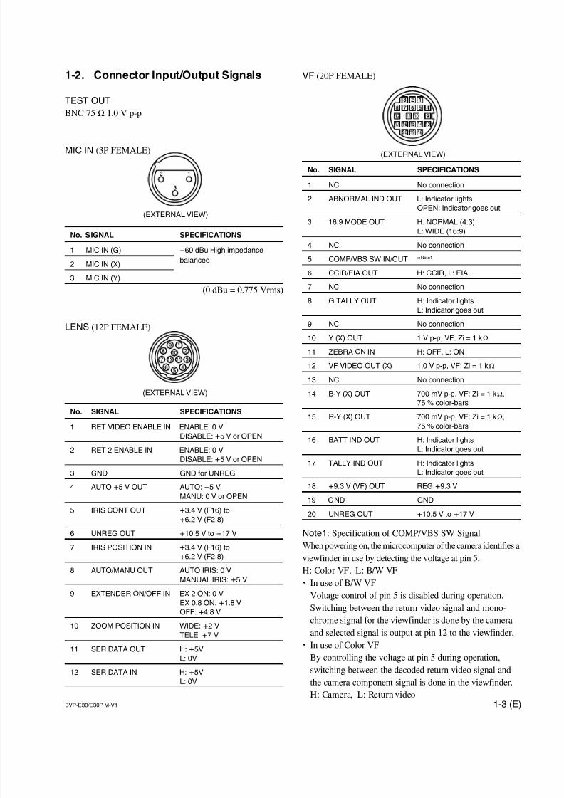
1-2. Connector Input/Output Signals
TEST OUT
BNC 75 Z 1.0 V p-p
MIC IN (3P FEMALE)
No. SIGNAL SPECIFICATIONS
1 MIC IN (G) _60 dBu High impedance
2 MIC IN (X)balanced
3 MIC IN (Y)(0 dBu = 0.775 Vrms)
LENS (12P FEMALE)
No. SIGNAL SPECIFICATIONS
1 RET VIDEO ENABLE IN ENABLE: 0 V
DISABLE: +5 V or OPEN
2 RET 2 ENABLE IN ENABLE: 0 V
DISABLE: +5 V or OPEN
3 GND GND for UNREG
4 AUTO +5 V OUT AUTO: +5 V
MANU: 0 V or OPEN
5 IRIS CONT OUT +3.4 V (F16) to
+6.2 V (F2.8)
6 UNREG OUT +10.5 V to +17 V
7 IRIS POSITION IN +3.4 V (F16) to
+6.2 V (F2.8)8 AUTO/MANU OUT AUTO IRIS: 0 V
MANUAL IRIS: +5 V
9 EXTENDER ON/OFF IN EX 2 ON: 0 V
EX 0.8 ON: +1.8 V
OFF: +4.8 V
10 ZOOM POSITION IN WIDE: +2 V
TELE: +7 V
11 SER DATA OUT H: +5V
L: 0V
12 SER DATA IN H: +5V
L: 0V
VF (20P FEMALE)
No. SIGNAL SPECIFICATIONS
1 NC No connection
2 ABNORMAL IND OUT L: Indicator lights
OPEN: Indicator goes out
3 16:9 MODE OUT H: NORMAL (4:3)
L: WIDE (16:9)
4 NC No connection
5 COMP/VBS SW IN/OUT *Note1
6 CCIR/EIA OUT H: CCIR, L: EIA
7 NC No connection
8 G TALLY OUT H: Indicator lights
L: Indicator goes out
9 NC No connection
10 Y (X) OUT 1 V p-p, VF: Zi = 1 kZ
11 ZEBRA ON IN H: OFF, L: ON
12 VF VIDEO OUT (X) 1.0 V p-p, VF: Zi = 1 kZ
13 NC No connection
14 B-Y (X) OUT 700 mV p-p, VF: Zi = 1 kZ,
75 % color-bars
15 R-Y (X) OUT 700 mV p-p, VF: Zi = 1 kZ,75 % color-bars
16 BATT IND OUT H: Indicator lights
L: Indicator goes out
17 TALLY IND OUT H: Indicator lights
L: Indicator goes out
18 +9.3 V (VF) OUT REG +9.3 V
19 GND GND
20 UNREG OUT +10.5 V to +17 V
Note1: Specification of COMP/VBS SW Signal
When powering on, the microcomputer of the camera identifies a
viewfinder in use by detecting the voltage at pin 5.H: Color VF, L: B/W VF
. In use of B/W VF
Voltage control of pin 5 is disabled during operation.
Switching between the return video signal and mono-
chrome signal for the viewfinder is done by the camera
and selected signal is output at pin 12 to the viewfinder.
. In use of Color VF
By controlling the voltage at pin 5 during operation,
switching between the decoded return video signal and
the camera component signal is done in the viewfinder.
H: Camera, L: Return video
7/14/2019 Bvpe30mmi - Copy
http://slidepdf.com/reader/full/bvpe30mmi-copy 12/136
1-4 (E) BVP-E30/E30P M-V1
34
68
1
35
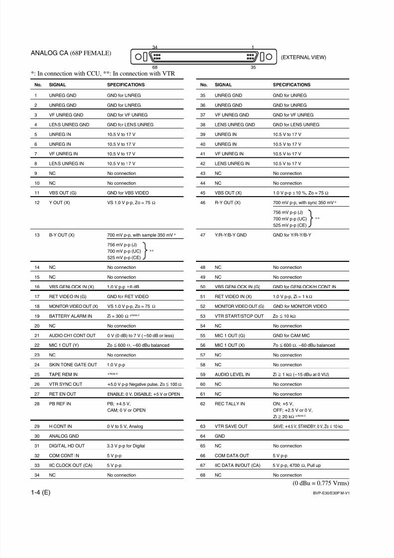
(EXTERNAL VIEW)
No. SIGNAL SPECIFICATIONS
1 UNREG GND GND for UNREG
2 UNREG GND GND for UNREG
3 VF UNREG GND GND for VF UNREG
4 LENS UNREG GND GND for LENS UNREG
5 UNREG IN 10.5 V to 17 V
6 UNREG IN 10.5 V to 17 V
7 VF UNREG IN 10.5 V to 17 V
8 LENS UNREG IN 10.5 V to 17 V
9 NC No connection
10 NC No connection
11 VBS OUT (G) GND for VBS VIDEO
12 Y OUT (X) VS 1.0 V p-p, Zo = 75 Z
13 B-Y OUT (X) 700 mV p-p, with sample 350 mV*
756 mV p-p (J)
700 mV p-p (UC) **
525 mV p-p (CE)
14 NC No connection
15 NC No connection
16 VBS GENLOCK IN (X) 1.0 V p-p ±6 dB
17 RET VIDEO IN (G) GND for RET VIDEO
18 MONITOR VIDEO OUT (X) VS 1.0 V p-p, Zo = 75 Z
19 BATTERY ALARM IN Zi = 300 Z *Note 2
20 NC No connection
21 AUDIO CH1 CONT OUT 0 V (0 dB) to 7 V (_50 dB or less)
22 MIC 1 OUT (Y) Zo < 600 Z, _60 dBu balanced
23 NC No connection
24 SKIN TONE GATE OUT 1.0 V p-p
25 TAPE REM IN *Note 4
26 VTR SYNC OUT +5.0 V p-p Negative pulse, Zo < 100 Z
27 RET EN OUT ENABLE; 0 V, DISABLE; +5 V or OPEN
28 PB REF IN PB; +4.5 V,
CAM; 0 V or OPEN
29 H CONT IN 0 V to 5 V, Analog
30 ANALOG GND
31 DIGITAL HD OUT 3.3 V p-p for Digital
32 COM CONT IN 5 V p-p
33 IIC CLOCK OUT (CA) 5 V p-p
34 NC No connection
No. SIGNAL SPECIFICATIONS
35 UNREG GND GND for UNREG
36 UNREG GND GND for UNREG
37 VF UNREG GND GND for VF UNREG
38 LENS UNREG GND GND for LENS UNREG
39 UNREG IN 10.5 V to 17 V
40 UNREG IN 10.5 V to 17 V
41 VF UNREG IN 10.5 V to 17 V
42 LENS UNREG IN 10.5 V to 17 V
43 NC No connection
44 NC No connection
45 VBS OUT (X) 1.0 V p-p ±10 %, Zo = 75 Z
46 R-Y OUT (X) 700 mV p-p, with sync 350 mV*
756 mV p-p (J)
700 mV p-p (UC) **
525 mV p-p (CE)
47 Y/R-Y/B-Y GND GND for Y/R-Y/B-Y
48 NC No connection
49 NC No connection
50 VBS GENLOCK IN (G) GND for GENLOCK/H CONT IN
51 RET VIDEO IN (X) 1.0 V p-p, Zi = 1 kZ
52 MONITOR VIDEO OUT (G) GND for MONITOR VIDEO
53 VTR START/STOP OUT Zo < 10 kZ
54 NC No connection
55 MIC 1 OUT (G) GND for CAM MIC
56 MIC 1 OUT (X) Zo < 600 Z, _60 dBu balanced
57 NC No connection
58 NC No connection
59 AUDIO LEVEL IN Zi > 1 kZ (_15 dBu at 0 VU)
60 NC No connection
61 NC No connection
62 REC TALLY IN ON; +5 V,
OFF; +2.5 V or 0 V,
Zi > 20 kZ *Note 3
63 VTR SAVE OUT SAVE; +4.5 V, STANDBY; 0 V, Zo < 10 kZ
64 GND
65 NC No connection
66 COM DATA OUT 5 V p-p
67 IIC DATA IN/OUT (CA) 5 V p-p, 4700 Z, Pull up
68 NC No connection
(0 dBu = 0.775 Vrms)
ANALOG CA (68P FEMALE)
*: In connection with CCU, **: In connection with VTR
7/14/2019 Bvpe30mmi - Copy
http://slidepdf.com/reader/full/bvpe30mmi-copy 13/136
1-5 (E)BVP-E30/E30P M-V1
Input Signal at
Pin 62
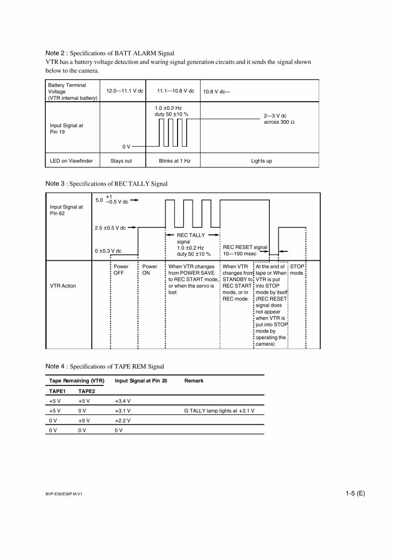
5.0
REC TALLY
signal1.0 ±0.2 Hzduty 50 ±10 %
REC RESET signal
10—100 msec
VTR Action
Power
OFF
Power
ON
When VTR changes
from POWER SAVE
to REC START mode,
or when the servo is
lost
When VTR
changes from
STANDBY to
REC START
mode, or inREC mode
At the end of
tape or When
VTR is put
into STOP
mode by itself(REC RESET
signal does
not appear
when VTR is
put into STOP
mode by
operating the
camera)
STOP
mode
+1_0.5 V dc
2.5 ±0.5 V dc
0 ±0.3 V dc
Battery Terminal
Voltage
(VTR internal battery)
12.0—11.1 V dc 11.1—10.8 V dc 10.8 V dc—
2—3 V dcacross 300 Z
0 V
Input Signal at
Pin 19
LED on Viewfinder
1.0 ±0.2 Hzduty 50 ±10 %
Stays out Blinks at 1 Hz Lights up
Note 2 : Specifications of BATT ALARM Signal
VTR has a battery voltage detection and waring signal generation circuits and it sends the signal shown
below to the camera.
Note 3 : Specifications of REC TALLY Signal
Note 4 : Specifications of TAPE REM Signal
Tape Remaining (VTR) Input Signal at Pin 25 Remark
TAPE1 TAPE2
+5 V +5 V +3.4 V
+5 V 0 V +3.1 V G TALLY lamp lights at +3.1 V
0 V +5 V +2.2 V
0 V 0 V 0 V
7/14/2019 Bvpe30mmi - Copy
http://slidepdf.com/reader/full/bvpe30mmi-copy 14/136
1-6 (E) BVP-E30/E30P M-V1
34
68
1
35
(EXTERNAL VIEW)
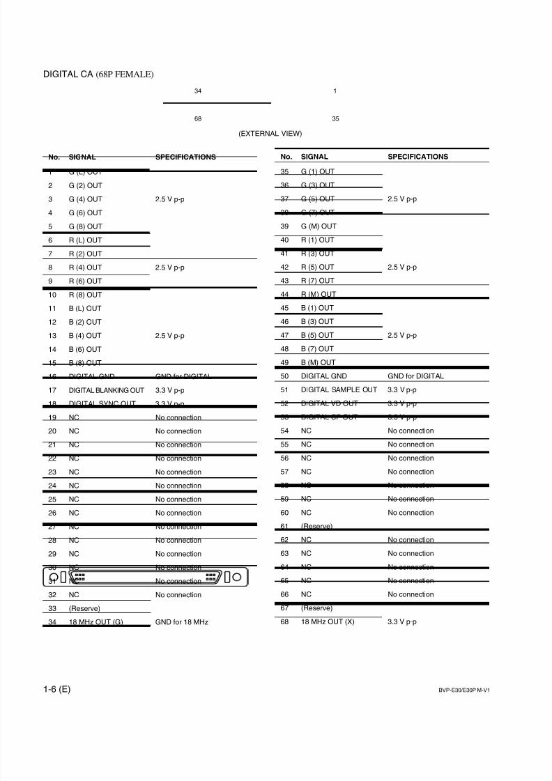
DIGITAL CA (68P FEMALE)
No. SIGNAL SPECIFICATIONS
1 G (L) OUT
2 G (2) OUT
3 G (4) OUT 2.5 V p-p
4 G (6) OUT
5 G (8) OUT
6 R (L) OUT
7 R (2) OUT
8 R (4) OUT 2.5 V p-p
9 R (6) OUT
10 R (8) OUT
11 B (L) OUT
12 B (2) OUT
13 B (4) OUT 2.5 V p-p
14 B (6) OUT
15 B (8) OUT
16 DIGITAL GND GND for DIGITAL
17 DIGITAL BLANKING OUT 3.3 V p-p
18 DIGITAL SYNC OUT 3.3 V p-p
19 NC No connection
20 NC No connection
21 NC No connection
22 NC No connection
23 NC No connection
24 NC No connection
25 NC No connection
26 NC No connection
27 NC No connection
28 NC No connection
29 NC No connection
30 NC No connection
31 NC No connection
32 NC No connection
33 (Reserve)
34 18 MHz OUT (G) GND for 18 MHz
No. SIGNAL SPECIFICATIONS
35 G (1) OUT
36 G (3) OUT
37 G (5) OUT 2.5 V p-p
38 G (7) OUT
39 G (M) OUT
40 R (1) OUT
41 R (3) OUT
42 R (5) OUT 2.5 V p-p
43 R (7) OUT
44 R (M) OUT
45 B (1) OUT
46 B (3) OUT
47 B (5) OUT 2.5 V p-p
48 B (7) OUT
49 B (M) OUT
50 DIGITAL GND GND for DIGITAL
51 DIGITAL SAMPLE OUT 3.3 V p-p
52 DIGITAL VD OUT 3.3 V p-p
53 DIGITAL CF OUT 3.3 V p-p
54 NC No connection
55 NC No connection
56 NC No connection
57 NC No connection
58 NC No connection
59 NC No connection
60 NC No connection
61 (Reserve)
62 NC No connection
63 NC No connection
64 NC No connection
65 NC No connection
66 NC No connection
67 (Reserve)
68 18 MHz OUT (X) 3.3 V p-p
7/14/2019 Bvpe30mmi - Copy
http://slidepdf.com/reader/full/bvpe30mmi-copy 15/136
1-7 (E)BVP-E30/E30P M-V1
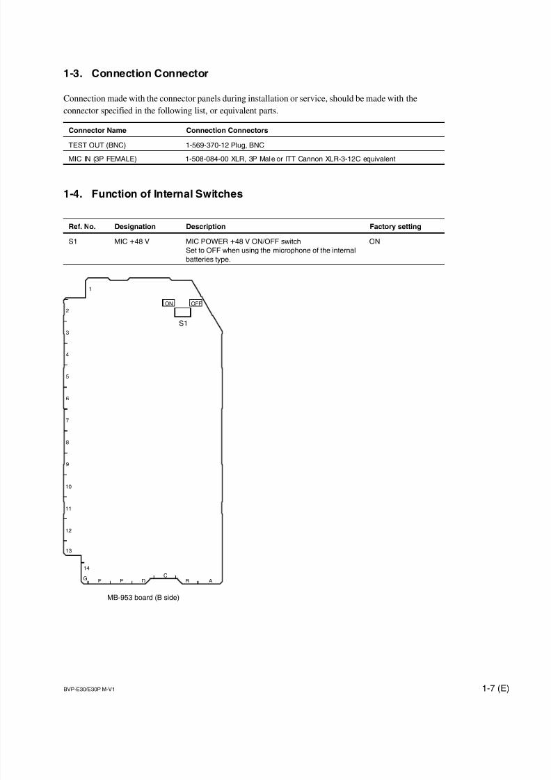
1-3. Connection Connector
Connection made with the connector panels during installation or service, should be made with the
connector specified in the following list, or equivalent parts.
Connector Name Connection Connectors
TEST OUT (BNC) 1-569-370-12 Plug, BNC
MIC IN (3P FEMALE) 1-508-084-00 XLR, 3P Male or ITT Cannon XLR-3-12C equivalent
1-4. Function of Internal Switches
Ref. No. Designation Description Factory setting
S1 MIC +48 V MIC POWER +48 V ON/OFF switch ON
Set to OFF when using the microphone of the internal
batteries type.
S1
14
13
12
11
10
9
8
7
6
5
4
3
2
1
G F E DC
B A
MB-953 board (B side)
ON OFF
7/14/2019 Bvpe30mmi - Copy
http://slidepdf.com/reader/full/bvpe30mmi-copy 16/136
1-8 (E) BVP-E30/E30P M-V1
S1
8
7
6
5
4
3
2
1
ABCD
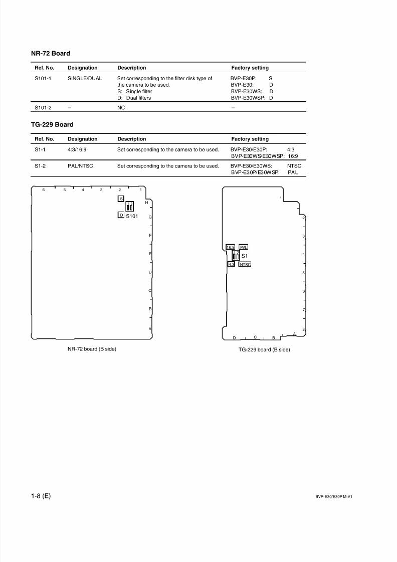
TG-229 board (B side)
16:9 PAL
NTSC4:3
1 2
NR-72 Board
Ref. No. Designation Description Factory setting
S101-1 SINGLE/DUAL Set corresponding to the filter disk type of BVP-E30P: S
the camera to be used. BVP-E30: D
S: Single filter BVP-E30WS: D
D: Dual filters BVP-E30WSP: D
S101-2 _ NC _
TG-229 Board
Ref. No. Designation Description Factory setting
S1-1 4:3/16:9 Set corresponding to the camera to be used. BVP-E30/E30P: 4:3
BVP-E30WS/E30WSP: 16:9
S1-2 PAL/NTSC Set corresponding to the camera to be used. BVP-E30/E30WS: NTSC
BVP-E30P/E30WSP: PAL
S101
H
G
F
E
D
C
B
A
123456
NR-72 board (B side)
S
D
1 2
7/14/2019 Bvpe30mmi - Copy
http://slidepdf.com/reader/full/bvpe30mmi-copy 17/136
1-9 (E)BVP-E30/E30P M-V1
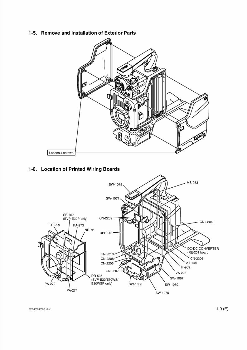
Loosen 4 screws.
MB-953
CN-2204
DC-DC CONVERTER(RE-201 board)
CN-2206
AT-148
VA-226
SW-1069
SW-1067
SW-1070
SW-1068
CN-2207
CN-2205
CN-2208
CN-2210
DPR-261
CN-2209
SW-1071
SW-1075
IF-969
DR-536(BVP-E30/E30WS/ E30WSP only)
PA-274
PA-272
PA-273
SE-767(BVP-E30P only)
TG-229
NR-72
1-5. Remove and Installation of Exterior Parts
1-6. Location of Printed Wiring Boards
7/14/2019 Bvpe30mmi - Copy
http://slidepdf.com/reader/full/bvpe30mmi-copy 18/136
1-10 (E) BVP-E30/E30P M-V1
1-7. Circuit Description
1-7-1. CCD Block (PA-272/273/274 Boards,
TG-229 Board, and NR-72 Board)
PA-272/273/274 BoardsThe PA boards contains the CCD bias circuit, horizontal
register drive circuit (H1, H2, LH1 driver), CDS (Correlat-
ed Double Sampling) circuit which extracts video signals
from the CCD and eliminates noise, and preamp circuit
which adjusts sensitivity.
IC9 of PA-273 board detects temperature around the CCD
block with a temperature sensor, and sends the detected
signal to the AT-148 board.
Various CCD drive conditions, adjustment data (V-sub
voltage, RG voltage, black/white shading, etc.) are written
in IC8 (EEPROM) of PA-272 board.
TG-229 Board
The TG-229 board contains the CCD drive pulse genera-
tion circuit and its drive circuit.
The 18 MHz clock generated from the voltage control
generation circuit (X1) is sent to the DPR-261 board to
generate the AHD, AVD pulse synchronized with the
video output signal.
The TG IC (IC1) generates the CCD drive pulse synchro-
nized with this AHD, AVD pulse and the sample and hold
pulse for the CDS circuit of the PA boards.
These pulses are passed through the following drive circuit
and are sent to each PA board.
. V clock: Passed through IC201 to IC206 drivers ICs
. RG pulse: Passed through IC309 and then the bias
potential specific to each. CCD is added to the
output of IC309.
. V-sub voltage:
Enters IC310 DC amplifier to be adjusted for
the specified voltage.
. Shutter pulse:
Passes through the drive circuit consisting of
Q201 to Q204.. SHP/SHD/H1/H2/LH1:
Passes through IC312, IC313, and IC307
AND gate ICs.
NR-72 Board
The NR-72 board contains a power stabilization circuit to
stabilize various power supply voltages to be supplied to
the CCD block, black/white shading correction signal
generation circuit, and optical filter interface circuits.
. The power stabilization circuit stabilizes the followingpower supply voltages to be supplied to the CCD block.
+15.0 V +30.0 V +6.0 V +5.3 V +3.3 V +2.5 V
+1.8 V +1.1 V _10.0V _8.0 V _4.5 V
. The black/white shading correction signal and TEST
SAW signal are generated in IC104, and are sent to the
VA-226 board to mix with the video signal.
. This board has two optical filter interface circuits, one is
for the two-filters type with a servomotor used in the
BVP-E30/E30WS/E30WSP, the other is for one filter
type without a servomotor used in the BVP-E30P.
The switch S101 switches these circuits.
7/14/2019 Bvpe30mmi - Copy
http://slidepdf.com/reader/full/bvpe30mmi-copy 19/136
1-11 (E)BVP-E30/E30P M-V1
1-7-2. Video Signal System (VA-226 Board,
DPR-261 Board, and IF-969 Board)
VA-226 Board
The VA-226 circuit amplifies the R, G, B video signals
output from the PA boards, performs various correction,and then sends them to the DPR-261 board. As the R, G,
and B circuits are basically the same, Rch is explained as
an example below.
The video signal output from the PA board is passed
through the trap filter (FL101), and input to the first
amplifier stage composed of Q102 to Q108. In this ampli-
fier, black shading correction, 5600K switching (Rch and
Bch only) and clamping are performed.
The clamped signal is switched between 0 dB/6 dB/12 dB/
18 dB by the amplifier composed of Q110 to Q117 and
blanking cleaning is performed by IC102. Clamping is also
performed in this amplifier.
After this, the change of 0 dB/3 dB/6 dB/12 dB and flare
correction are performed in the amplifier composed of
Q125 to Q131 and Q133 to Q135, and the signals are
output to the DPR-261 board.
In addition, switching of the video signal and TEST SAW
signal is also performed.
DPR-261 Board
The DPR-261 board is mainly composed of the A/D block
which converts analog RGB signals input from the VA-
226 board to digital, camera DSP (digital signal processor)
block which performs various signal processing, and D/A
block which converts digital signals processed by thecamera DSP block to analog.
In the A/D block, after analog RGB signals input from the
VA-226 board are clamped, they are passed through the
pre-filters (FL101, FL102, and FL103), and converted to
14-bit digital signals by the A/D converter (IC102, IC202,
and IC302).
The A/D-converted digital signals are input to the camera
DSP LSI (IC1).
IC1 performs detection of average values and peak values
of video signals required for automatic operations of the
camera such as auto black balance, auto white balance,
auto iris, etc., processings white balance, white shading
correction, matrix, detail, and gamma, and digital encoding
for VBS signals. 25 PsF/29.94 PsF conversion functions
and slow shutter are also realized using the SDRAM
(IC801). These processed signals are output from IC1 as
various digital video signals.
Of the digital video signals output from IC1, only the Y/R-
Y/B-Y signals for the digital CA are passed through the
buffers (IC1001 to IC1005) and then output at the DPR-
261 board as the digital signals. The other digital signals
are converted to analog signal.
In the D/A block, the Y/R-Y/B-Y signal is D/A-converted
by IC501, the VBS/SC by IC502, the Y/R-Y/B-Y signal
for VF by IC503, and the TEST signal by IC800.
The DPR-261 board, also control PLL and H-Phase/SC-
Phase at genlock and generates various timing pulses such
as HD/VD/SYNC.
7/14/2019 Bvpe30mmi - Copy
http://slidepdf.com/reader/full/bvpe30mmi-copy 20/136
1-12 (E) BVP-E30/E30P M-V1
IF-969 Board
The IF-969 board is composed of the driver block which
switches and outputs the analog signals D/A converted by
the DPR-261 board and RET signal sent when CCU is
connected to each block, and the I/O block inputs/outputs
the control signals from/to the lens, VF and the cameraadaptor.
The VBS signal which is D/A-converted by the DPR-261
board is input to the IF-969 board and branched into two.
One is sent to the camera adaptor as VBS output by 75 Zoutput driver after passed through the video driver IC
(IC105). The other is switched by the analog switch IC
(IC104) and output at the TEST OUT terminal.
This unit has the two systems to output the TEST signal.
One system outputs the TEST signal as a MONITOR OUT
to the camera adaptor after being switched by IC104
analog switch.
The other outputs that at the TEST OUT terminal by the
75 Z output driver after passing through IC105 driver IC.
At this terminal, VBS, TEST or RET signals which is
selected by IC104 analog switch is output. According to
another switch setting, character signal can be added to the
above output signal.
The RET signal sent when CCU is connected and the
GENLOCK input signal from the camera adaptor are
switched by the analog switch circuit (Q101 to Q107) and
the RET signal is separated to two pathes. The one is
output at the TEST OUT terminal via the analog switch IC
(IC104) after switching between the RET signal and the
TEST signal is done by the analog switch circuit (Q126,
Q115 to Q117, IC2). The other is output to VF VIDEO
OUT after switching between the RET signal and the VF-
VIDEO signal is done by the analog switch circuit (Q4 to
Q6). And also, to synchronize the GENLOCK input of the
camera adaptor with the external input video signal, the IF-
969 board is provided with the floating amplifier circuit
and sync separation circuit to send the external sync
signals EXT-SC and EXT-SYNC to the DPR-261 board.
When a color VF is connected, the signals VF-Y, VF R-Y,
VF B-Y input from the DPR-261 board are mixed with thecursor, marker signal and character signal generated in the
character generator IC (IC5) and then output as a COLOR
VF signal.
When a white/black VF is connected, the VF-Y signal
input from the DPR-261 board are mixed with the cursor,
marker and character signals in the different block to the
COLOR VF signal and then output to VF VIDEO OUT as
a monochrome VF signal.
The I/O block controls the switching input signal from the
switches of the camera, input/output signals from/to the
camera adaptor and lens, and output signal to VF using the
I/O expander (IC307) which communicates with the AT-
148 board.
1-7-3. System Control (AT-148 Board)
AT-148 Board
The AT-148 board is provided with a CPU (IC11) which
performs system control.
It is operated by the program written in the ROM (IC231
and IC232). The program can be upgraded using a memory
stick via the controller IC222.
The AT-148 board is also provided with a general memory
SRAM (IC216 and IC217) and FRAM (IC220 and IC221)
for recording system setting conditions, etc.
The external 8-bit bus (IC205, IC206, IC207, and IC208)
controls the I/O expander (IC307) of the IF-969 board and
the digital signal processor LSI (IC1) of the DPR-261
board. It also controls IC1 of the TG-229 board, IC104 of
the NR-72 board, D/A converter (IC702 and IC704) of the
VA-226 board, D/A converter (IC504 and IC509) of the
DPR-261 board, and switch input (IC1001 and IC1002) of
the CN-2205 board by serial communication.
The A/D converter of the CPU reads the IRIS, ZOOM, and
EXTENDER signals from the lens, and controls the lens
via the channel B of the communication IC (IC224).
In additional the CPU performs temperature control using
the temperature sensor signal of channel G sent from the
CCD block (PA-273 board), position control from the filter
block, tape remainder control, and audio volume control.
It is also provided with the serial I/O which communicates
with the CCU using the 700 protocol (channel A of IC224)
and the calendar function (IC3).

7/14/2019 Bvpe30mmi - Copy
http://slidepdf.com/reader/full/bvpe30mmi-copy 21/136
1-13 (E)BVP-E30/E30P M-V1
1-7-4. Power Supply Block (DC-DC
Converter) (RE-201 Board)
RE-201 Board
. The RE-201 board is a DC-DC converter which outputs
11 types of voltages altogether.
. PWM Clock Signal
The PWM POWER CONTROL (IC8) generates and
supplies the master clock (triangular wave of 90 ±10
kHz) for all controller ICs (IC2, IC3, IC7, and IC8) .
. Input Voltage Monitoring Circuit
The RE-201 board has an input voltage monitoring
circuit (IC4). If the voltage is within the appropriate
range, it supplies power to each controller IC (IC2, IC3,
IC7, and IC8) and REF voltage IC (IC1).
The power supply circuit starts up when the input power
voltage is within the range of +10.0 V to +18.8 V. Once
it has started up, the circuit keeps operating until the
input power voltage decreases below the lower limit
(+9.4 V).
. Protection Circuit for Shorting of Output Circuit
Each output is connected with a diode or transistor. In
normal operations, they are reverse-biased so that they
are turned OFF.
However if any single output is shorted, or if there is no
output due to some defect, the diode and transistor of the
corresponding block are turned ON and IC9 sends a
L_SHUTDOWN signal. The master clock is stopped by
this signal, and the outputs of all voltages stop.
. Output Overvoltage Protection Circuit
An overvoltage detection circuit is equipped only for the
+1.4 V output.
When the +1.4 V output exceeds +2.0 V under abnor-
mal conditions, the outputs of all voltages are stopped by
the L_SHUTDOWN signal like the output short-circuit
protection circuit.
. Voltage Control Circuit
The eight output voltages out of the 11 voltages are
stabilized with direct feedback control by the PWM
POWER CONTROL (IC2, IC3, IC7, and IC8). Each
control IC can independently control two voltages each.
+1.4 V, +2.5 V, +5.3 V, +3.3 V, +6.6 V, and +9.3 Vare output from the step-down chopper circuit while
_5 V is output from the polarity reversed chopper
circuit. The sync rectification circuit is adopted for all
except +9.3V to obtain high efficiency.
_10.5 V is output from the flyback regulator using the
transformer T1. The three voltages +16.0 V, +32.0 V,
and +46.0 V are also output by the T1 coil, however
they are not directly stabilized.
For +1.4 V, accurate voltage is required.
Therefore, it detects the voltage in the DPR-261 board to
absorb voltage drop during transmission.
7/14/2019 Bvpe30mmi - Copy
http://slidepdf.com/reader/full/bvpe30mmi-copy 22/136
1-14 (E) BVP-E30/E30P M-V1
<DIAGNOSIS>
ROM:V1.00
CAMERA:UC CA-570
OHB:-- MD:--
VA :-- AU:--
DPR:-- TR:--
IF :--
AT :--
HUR:99999H
CCU :--
12
34
8
5
76
CA-570 CA-550
MD:-- MD:--AU:-- AU:--
TR:-- TR:--
CA-530 CA-950
VSE:-- DA :--
DVP:-- IF :--
DC :-- AU :--
SDI:--
DPR:--
TX :--
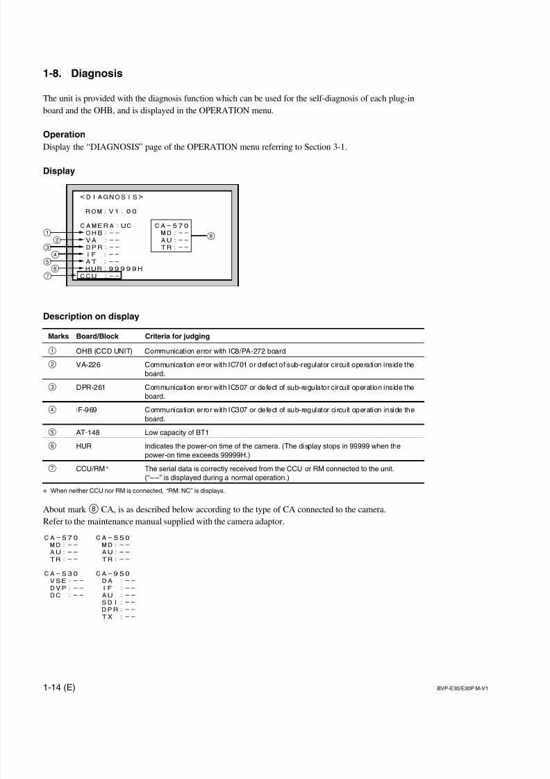
1-8. Diagnosis
The unit is provided with the diagnosis function which can be used for the self-diagnosis of each plug-in
board and the OHB, and is displayed in the OPERATION menu.
OperationDisplay the “DIAGNOSIS” page of the OPERATION menu referring to Section 3-1.
Display
Description on display
Marks Board/Block Criteria for judging
1 OHB (CCD UNIT) Communication error with IC8/PA-272 board
2 VA-226 Communication error with IC701 or defect of sub-regulator circuit operation inside the
board.
3 DPR-261 Communication error with IC507 or defect of sub-regulator circuit operation inside the
board.
4 IF-969 Communication error with IC307 or defect of sub-regulator circuit operation inside theboard.
5 AT-148 Low capacity of BT1
6 HUR Indicates the power-on time of the camera. (The display stops in 99999 when the
power-on time exceeds 99999H.)
7 CCU/RM * The serial data is correctly received from the CCU or RM connected to the unit.
(“__” is displayed during a normal operation.)
* When neither CCU nor RM is connected, “RM: NC” is displays.
About mark 8 CA, is as described below according to the type of CA connected to the camera.
Refer to the maintenance manual supplied with the camera adaptor.
7/14/2019 Bvpe30mmi - Copy
http://slidepdf.com/reader/full/bvpe30mmi-copy 23/136
1-15 (E)BVP-E30/E30P M-V1
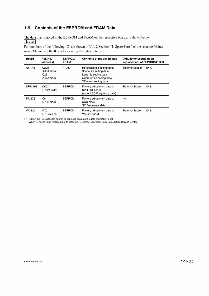
1-9. Contents of the EEPROM and FRAM Data
The data that is stored in the EEPROM and FRAM on the respective boards, is shown below.
nPart numbers of the following ICs are shown in Vol. 2 Section “1. Spare Parts” of the separate Mainte-
nance Manual are the ICs before saving the data contents.
Board Ref. No. EEPROM/ Contents of the saved data Adjustment/setup upon
(address) FRAM replacement of EEPROM/FRAM
AT-148 IC220 FRAM Reference file setting data Refer to Section 1-10-7.
(A-2/A side) Scene file setting data
IC221 Lens file setting data
(A-3/A side) Operator file setting data
VF menu setting data
DPR-261 IC507 EEPROM Factory adjustment data of Refer to Section 1-10-6.
(F-10/A side) DPR-261 board
(except SC Frequency data)
PA-272 IC8 EEPROM Factory adjustment data of *1
(B-1/B side) CCD block
SC Frequency data
VA-226 IC701 EEPROM Factory adjustment data of Refer to Section 1-10-5.
(D-12/A side) VA-226 board
*1: IC8 on the PA-272 board cannot be replaced because the data cannot be re-set.
When IC needs to be replaced due to defective IC, contact your local Sony Sales Office/Service Center.
7/14/2019 Bvpe30mmi - Copy
http://slidepdf.com/reader/full/bvpe30mmi-copy 24/136
1-16 (E) BVP-E30/E30P M-V1
1-10. Adjustment and Setting Items AfterReplacement of Board
When replacing the following boards, perform the adjust-
ments or settings referring to Section 5 “Electrical Align-
ment”If no adjustment item is listed, no adjustment is required.
Board Referring section
CCD unit 1-10-1. CCD Unit
TG-229 board 1-10-2. TG-229 Board
NR-72 board 1-10-3. NR-72 Board
VA-226 board 1-10-4. VA-226 Board
DPR-261 board 1-10-5. DPR-261 Board
AT-148 board 1-10-6. AT-148 Board
1-10-1. CCD Unit
Adjustment and Setting Items After CCD Unit is
Replaced
5-3-1. PA Gain Adjustment
5-4-3. SC Frequency Adjustment
4-7. OHB file (Adjustment and Saving the OHB file)
1-10-2. TG-229 Board
Setting Items After Board is Replaced
Referring to Section 1-4, set the internal switches.
1-10-3. NR-72 Board
Setting Items After Board is Replaced
Referring to Section 1-4, set the internal switch.
1-10-4. VA-226 Board
The EEPROM (IC701) is mounted on the VA-226 board.
Perform the following adjustments, when this IC is
replaced, too.
Adjustment Items After Board or EEPROM is
Replaced
5-2-1. Black Balance Adjustment
5-2-2. Offset Adjustment
5-2-3. Flare Offset Adjustment
1-10-5. DPR-261 Board
The EEPROM (IC507) is mounted on the DPR-261 board.
Perform the following adjustments, when this IC is
replaced, too.
Adjustment Items After Board or EEPROM is
Replaced
5-4-1. Video Level Adjustment
5-4-2. TEST OUT Level Adjustment
1-10-6. AT-148 Board
The unique setting data that is set by user is written into
IC220 and IC221 on the AT-148 board.
Therefore, when these ICs were replaced with new ICs in
replacing the board or IC itself, the data set by user is lost,
and is returned to their factory-setting values.
Perform the following settings, when these ICs are re-
placed, too.
Setting Items After Board or FRAM is Replaced
. Reset the reference file, operator file and scene file.(Refer to Section 4.)
. Replace lithium battery on the AT-148 board with a new
one, and reset date. (Refer to Sections 1-1-5 and 3-5.)
7/14/2019 Bvpe30mmi - Copy
http://slidepdf.com/reader/full/bvpe30mmi-copy 25/136
1-17 (E)BVP-E30/E30P M-V1
1-11. Upgrading the Software
The version of the MAIN program and BOOT program can
be upgraded using the memory stick. According to neces-
sary, follow the procedures shown below.
m. The upgrading program must have already been saved in
a memory stick before.
. Refer to Section 5-1-6 to display of the SERVICE menu.
. Refer to Section 3-1 for the basic operations of the setup
menu.
1-11-1. Upgrading MAIN Program
When the Setup Menu is Used for Version
Upgrading
1. Insert the memory stick in which the upgrading
program is already saved.
2. Display the FIRM UPDATE page of the SERVICE
menu, and execute the MAIN PROGRAM.
3. The upgrading status is displayed on the viewfinder
screen.
4. When the version upgrade is completed, the message
“Complete” will be displayed.
nWhen the tally switch on the camera adaptor is set to
ON, the tally lamp will blink during being upgrading,
and then light up when upgrading is completed.
5. Restart the unit, and confirm the version indication
using DIAGNOSIS menu.
Upgrading by Powering ON the Unit
1. Insert the memory stick in which the upgrading
program is already saved.
2. Turn on the power while pressing the VTR START
switch and MENU SELECT knob on the camera front
simultaneously.3. The upgrading status is displayed on the viewfinder
screen.
4. When the version upgrade is completed, the message
“Complete” will be displayed.
nWhen the tally switch on the camera adaptor is set to
ON, the tally lamp will blink during being upgrading,
and then light up when upgrading is completed.
5. Restart the unit, and confirm the version indication
using DIAGNOSIS menu.
1-11-2. Upgrading BOOT Program
BOOT program is a software renewing the firmware using
the memory stick. Do not operate this program except
upgrading the program.
1. Insert the memory stick in which the upgrading
program is already saved.
2. Display the FIRM UPDATE page of the SERVICE
menu, and execute the BOOT PROGRAM.
3. When the version upgrade is completed, the message
“Complete” will be displayed.
nWhen the tally switch on the camera adaptor is set to
ON, the tally lamp will blink during being upgrading,
and then light up when upgrading is completed.
7/14/2019 Bvpe30mmi - Copy
http://slidepdf.com/reader/full/bvpe30mmi-copy 26/136
1-18 (E) BVP-E30/E30P M-V1
1-12. Setting Scene File Number
The number of scene files that can be registered can be
changed (to 5 or 32) using the SERVICE menu of this unit.
The number of scene files can be stored in the internal
memory of this unit, memory stick, and IC memory card(when MSU is used).
However, pay attention to the following when changing the
number of scene files again after it is changed.
When the number of scene files is switched from
5 to 32:
Indefinite data is registered in the values of scene files 6 to
32. Be sure to register new data again before using the
scene files.
When the number of scene files is switched from
32 to 5:
The data registered in scene files 6 to 32 is deleted. The
deleted data cannot be restored.
m. This setting corresponds only to MSU-700A/750 and
RCP-730 series.
. Each scene file have no compatibility among the camer-
as if their scene file number differs.
How to change
Change the scene file number using the SETUP page in the
SERVICE menu.
Refer to Section 5-1-6 to display of the SERVICE menu.
Menu setting:
MENU: SERVICE
PAGE: SETUP
ITEM: SCENE FILE TYPE→ 5 or 32
7/14/2019 Bvpe30mmi - Copy
http://slidepdf.com/reader/full/bvpe30mmi-copy 27/136
1-19 (E)BVP-E30/E30P M-V1
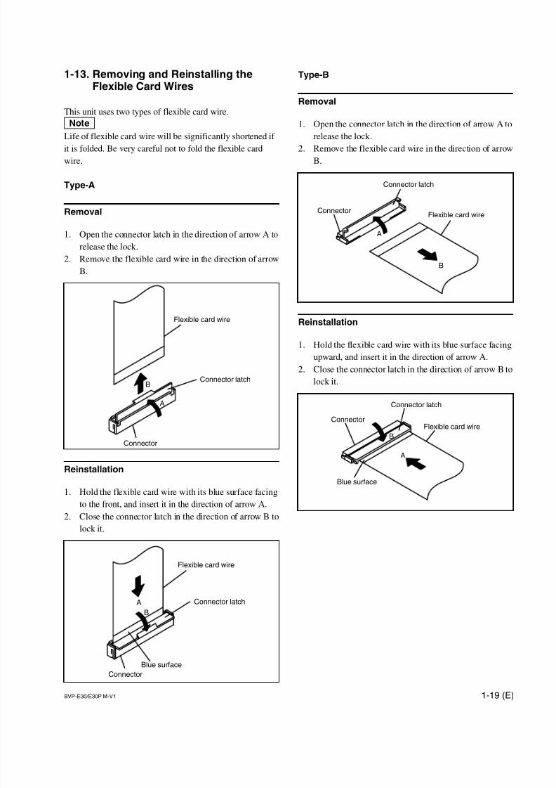
1-13. Removing and Reinstalling theFlexible Card Wires
This unit uses two types of flexible card wire.
n
Life of flexible card wire will be significantly shortened if it is folded. Be very careful not to fold the flexible card
wire.
Type-A
Removal
1. Open the connector latch in the direction of arrow A to
release the lock.
2. Remove the flexible card wire in the direction of arrow
B.
Reinstallation
1. Hold the flexible card wire with its blue surface facing
to the front, and insert it in the direction of arrow A.
2. Close the connector latch in the direction of arrow B to
lock it.
Type-B
Removal
1. Open the connector latch in the direction of arrow A to
release the lock.2. Remove the flexible card wire in the direction of arrow
B.
Reinstallation
1. Hold the flexible card wire with its blue surface facing
upward, and insert it in the direction of arrow A.
2. Close the connector latch in the direction of arrow B to
lock it.
Flexible card wireConnector
Connector latch
A
B
Flexible card wireConnector
Connector latch
A
B
Blue surface
Flexible card wire
Connector
Connector latch
A
B
Flexible card wire
Connector
Connector latchA
B
Blue surface
7/14/2019 Bvpe30mmi - Copy
http://slidepdf.com/reader/full/bvpe30mmi-copy 28/136
1-20 (E) BVP-E30/E30P M-V1
CN10/MB-953 board
EX-878 board
DC-DC converter
CN2
CN3
CN1
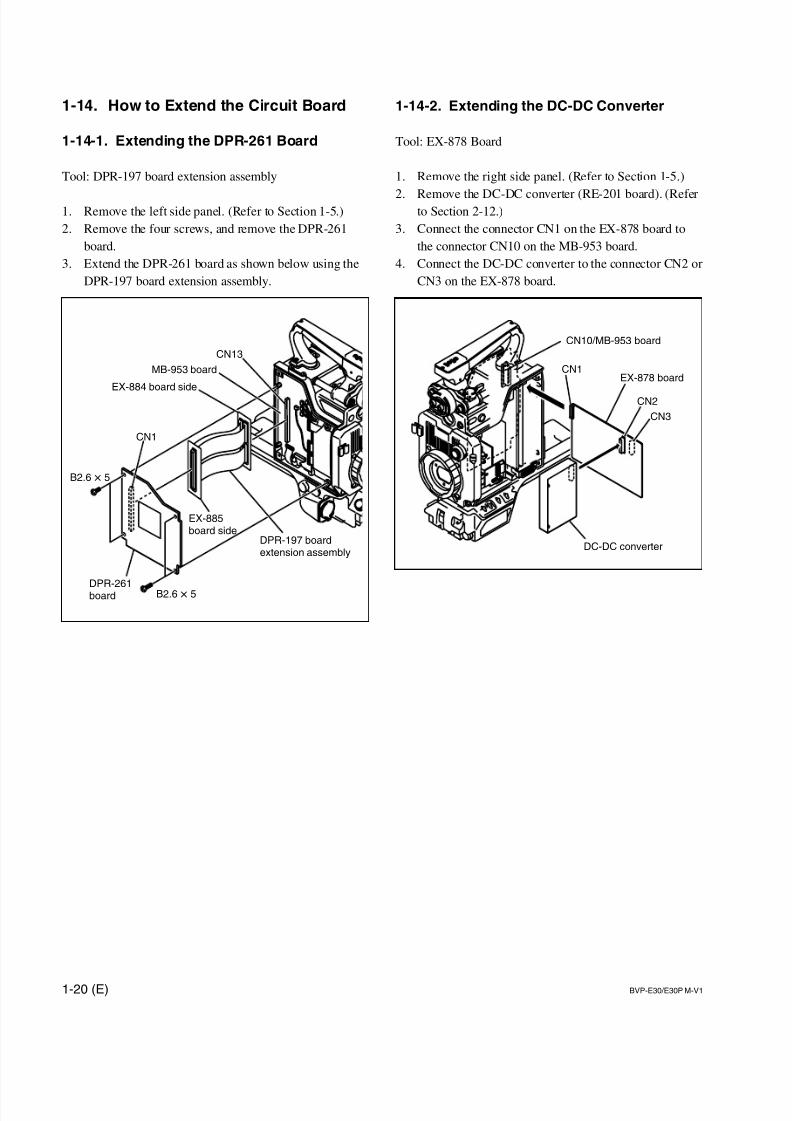
1-14. How to Extend the Circuit Board
1-14-1. Extending the DPR-261 Board
Tool: DPR-197 board extension assembly
1. Remove the left side panel. (Refer to Section 1-5.)
2. Remove the four screws, and remove the DPR-261
board.
3. Extend the DPR-261 board as shown below using the
DPR-197 board extension assembly.
1-14-2. Extending the DC-DC Converter
Tool: EX-878 Board
1. Remove the right side panel. (Refer to Section 1-5.)
2. Remove the DC-DC converter (RE-201 board). (Referto Section 2-12.)
3. Connect the connector CN1 on the EX-878 board to
the connector CN10 on the MB-953 board.
4. Connect the DC-DC converter to the connector CN2 or
CN3 on the EX-878 board.
DPR-261board
CN1
B2.6 x 5
B2.6 x 5
MB-953 board
EX-885board side
EX-884 board side
CN13
DPR-197 boardextension assembly
7/14/2019 Bvpe30mmi - Copy
http://slidepdf.com/reader/full/bvpe30mmi-copy 29/136
1-21 (E)BVP-E30/E30P M-V1
CCD block
EX Harness
CN6
MB-953 board
CN5 CN4
RCN4 Red
CN5
CN6
EX Harness
Yellow
Blue
G
B
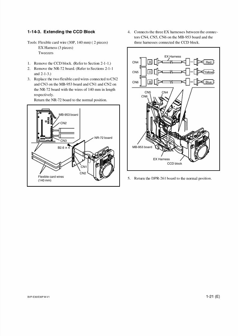
1-14-3. Extending the CCD Block
Tools: Flexible card wire (30P, 140 mm) ( 2 pieces)
EX Harness (3 pieces)
Tweezers
1. Remove the CCD block. (Refer to Section 2-1-1.)
2. Remove the NR-72 board. (Refer to Sections 2-1-1
and 2-1-3.)
3. Replace the two flexible card wires connected to CN2
and CN3 on the MB-953 board and CN1 and CN2 on
the NR-72 board with the wires of 140 mm in length
respectively.
Return the NR-72 board to the normal position.
4. Connects the three EX harnesses between the connec-
tors CN4, CN5, CN6 on the MB-953 board and the
three harnesses connected the CCD block.
5. Return the DPR-261 board to the normal position.
CN2
CN1
CN2
CN3NR-72 board
Flexible card wires(140 mm)
MB-953 board
B2.6 x 4
7/14/2019 Bvpe30mmi - Copy
http://slidepdf.com/reader/full/bvpe30mmi-copy 30/136
1-22 (E) BVP-E30/E30P M-V1
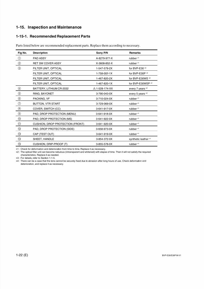
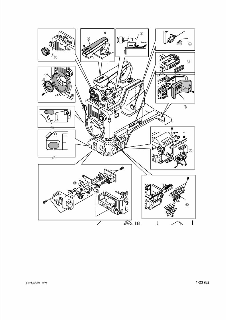
1-15. Inspection and Maintenance
1-15-1. Recommended Replacement Parts
Parts listed below are recommended replacement parts. Replace them according to necessary.
Fig No. Description Sony P/N Remarks
1 PAD ASSY A-8279-977-X rubber *1
2 RET SW COVER ASSY X-3608-852-X rubber *1
3 FILTER UNIT, OPTICAL 1-547-579-2X for BVP-E30 *2
FILTER UNIT, OPTICAL 1-758-002-1X for BVP-E30P *2
FILTER UNIT, OPTICAL 1-467-820-2X for BVP-E30WS *2
FILTER UNIT, OPTICAL 1-467-820-1X for BVP-E30WSP *2
4 BATTERY, LITHIUM CR-2032 ! 1-528-174-XX every 7 years *3
5 RING, BAYONET 3-790-043-0X every 5 years *4
6 PACKING, VF 3-710-024-0X rubber *1
7 BUTTON, VTR START 3-729-069-0X rubber *1
8 COVER, SWITCH (CC) 3-641-917-0X rubber *1
9 PAD, DROP PROTECTION (MENU) 3-641-918-0X rubber *1
0 PAD, DROP PROTECTION (MS) 3-641-922-0X rubber *1
!- CUSHION, DROP PROTECTION (FRONT) 3-641-920-0X rubber *1
!= PAD, DROP PROTECTION (SIDE) 3-658-973-0X rubber *1
![ CAP (TEST OUT) 3-641-919-0X rubber *1
!] SHEET, HANDLE 3-854-372-0X synthetic leather *1
!\ CUSHION, DRIP-PROOF (T) 3-855-578-0X rubber *1
*1 : Check for deformation and deterioration from time to time. Replace it as necessary.
*2 : The optical filter unit can become nebulous (intransparent and whitened) with elapse of time. Then it will not satisfy the requiredcharacteristics. Replace it as needed.
*3 : For details, refer to Section 1-1-5.
*4 : There can be a case that the lens cannot be securely fixed due to abrasion after long hours of use. Check deformation and
deterioration, and replace it as necessary.
7/14/2019 Bvpe30mmi - Copy
http://slidepdf.com/reader/full/bvpe30mmi-copy 31/136
1-23 (E)BVP-E30/E30P M-V1
2
3
5
9
0
4
8
1
7
!-

7/14/2019 Bvpe30mmi - Copy
http://slidepdf.com/reader/full/bvpe30mmi-copy 32/136
1-24 (E) BVP-E30/E30P M-V1
1-15-2. Cares after Using under Special Environment
Checking the followings is recommended when returned from the news gathering at seaside, at the dusty
locations, at hot spring, or if the unit is heavily splashed with water or water leaks in the unit in the rough
weather or the like.
1. Carefully clean off sand and dust that entered the unit with airbrush or the like.
2. If salt contained in seawater or sulfur contained in hot spring attaches o the non-painted surface of
outer cabinet, the cabinet may corrode in white. If it attaches, wipe it off immediately with alcohol.
3. If water leaks inside the unit, dry the unit with hair-dryer. Check especially that water does not
remain in the CCD block or the power supply block.
nIf the unit is not taken care of appropriately, corrosion may occur inside that may cause fire and
electric shock.
4. Clean out the contacting surface of connectors.
5. Perform the general operational check and confirm that the unit operates correctly without any
abnormality.
7/14/2019 Bvpe30mmi - Copy
http://slidepdf.com/reader/full/bvpe30mmi-copy 33/136
1-25 (E)BVP-E30/E30P M-V1
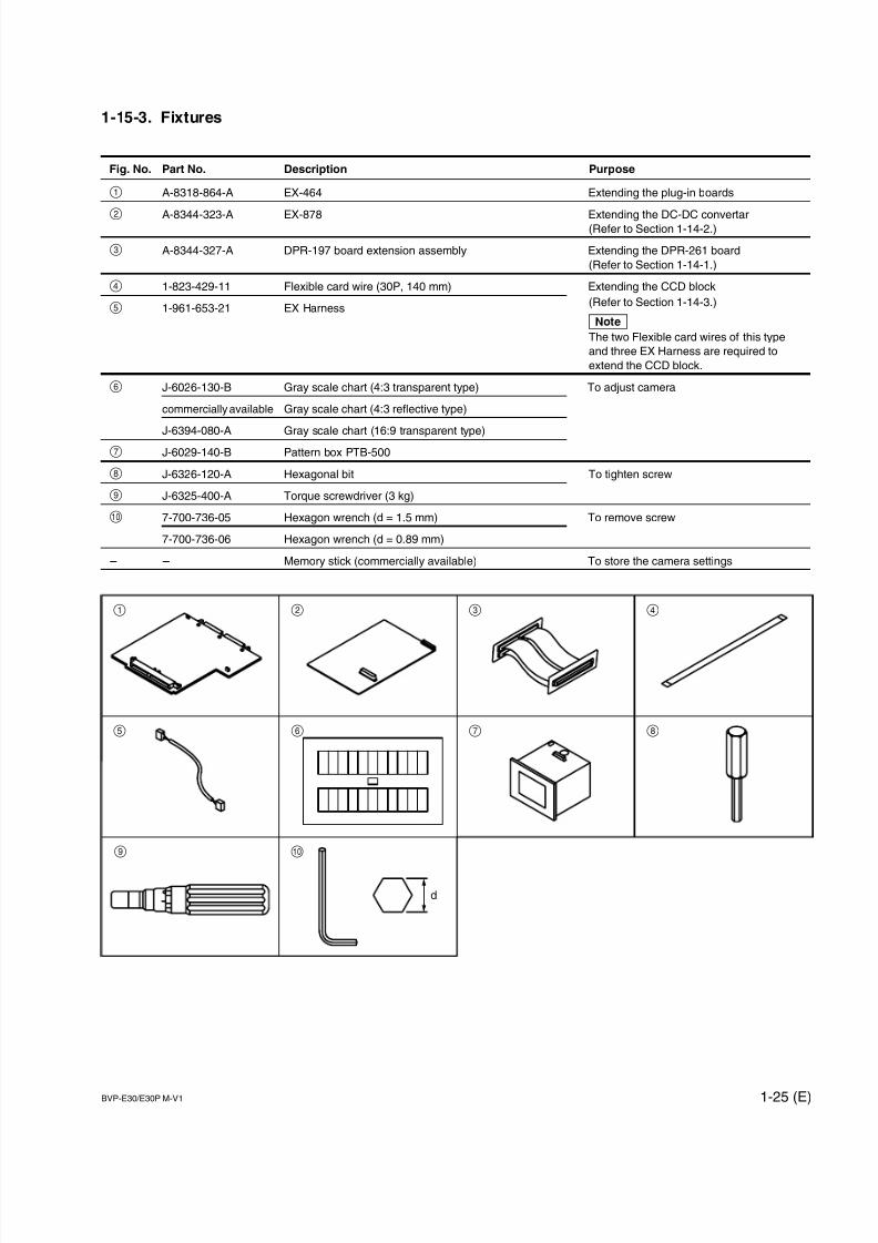
1-15-3. Fixtures
Fig. No. Part No. Description Purpose
1 A-8318-864-A EX-464 Extending the plug-in boards
2 A-8344-323-A EX-878 Extending the DC-DC convertar(Refer to Section 1-14-2.)
3 A-8344-327-A DPR-197 board extension assembly Extending the DPR-261 board
(Refer to Section 1-14-1.)
4 1-823-429-11 Flexible card wire (30P, 140 mm) Extending the CCD block
5 1-961-653-21 EX Harness(Refer to Section 1-14-3.)
nThe two Flexible card wires of this type
and three EX Harness are required to
extend the CCD block.
6 J-6026-130-B Gray scale chart (4:3 transparent type) To adjust camera
commercially available Gray scale chart (4:3 reflective type)
J-6394-080-A Gray scale chart (16:9 transparent type)7 J-6029-140-B Pattern box PTB-500
8 J-6326-120-A Hexagonal bit To tighten screw
9 J-6325-400-A Torque screwdriver (3 kg)
0 7-700-736-05 Hexagon wrench (d = 1.5 mm) To remove screw
7-700-736-06 Hexagon wrench (d = 0.89 mm)
_ _ Memory stick (commercially available) To store the camera settings
1 2 3 4
5 6 7 8
09
d
7/14/2019 Bvpe30mmi - Copy
http://slidepdf.com/reader/full/bvpe30mmi-copy 34/136
1-26 (E) BVP-E30/E30P M-V1
1-16. Notes for Replacing Parts
There are two kinds of types in the parts below used in this unit.
. Flexible card wires (Refer to Section 1-16-1.)
. Boards (Refer to Section 1-16-2.)
. Connectors on the board (for flexible card wires) (Refer to Section 1-16-3.)
When replacing the parts above, be sure to follow the instructions described in “1-16-1. Notes for Replacing the Flexible
Card Wire”, “1-16-2. Notes for Replacing the Board”, and “1-16-3. Notes for Replacing the Connector on the Board”.
Be sure to use the specified parts. Using un-specified parts causes the change in the characteristics of this unit and the unit
does not work properly.
Spare parts are listed in the spare parts list of “Spare Parts” Section. In the spare parts list, (GOLD) or (SILVER) is put
after each part name to distinguish two kinds of types (gold and silver).
1-16-1. Notes for Replacing the Flexible Card Wire
When replacing the flexible card wires listed below, confirm the conductive (terminal) part color of the flexible card wires
and follow the procedure below.
1. Replace the flexible card wire with a flexible card wire whose conductive part is gold when the conductive part of a
flexible card wire is gold.
nFor the board on which a connector whose contact surface is gold is used, “G” is put after the board name by silk-
screen printing or a “G” seal is attached to the empty space on the board. Example: CN-2205G
2. Replace the flexible card wire with a flexible card wire whose conductive part is silver when the conductive part of a
flexible card wire is silver. In this case, silk “G” or a “G” seal is not put on the board name.
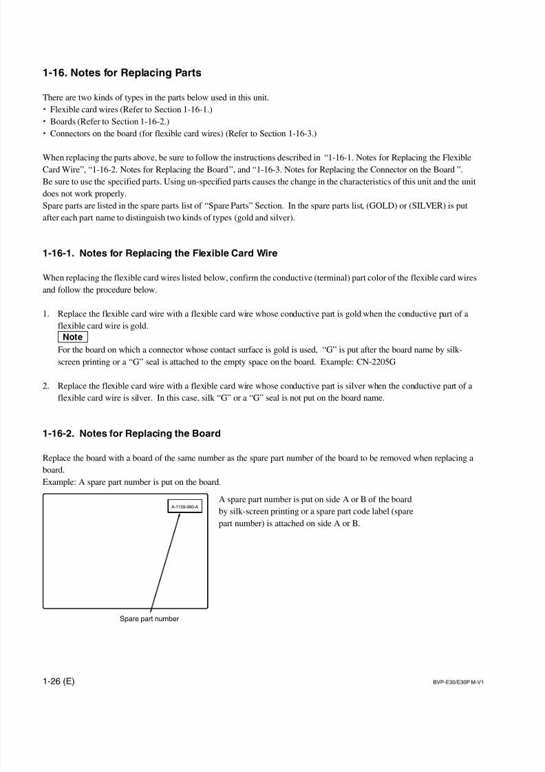
1-16-2. Notes for Replacing the Board
Replace the board with a board of the same number as the spare part number of the board to be removed when replacing a
board.
Example: A spare part number is put on the board.
A spare part number is put on side A or B of the board
by silk-screen printing or a spare part code label (spare
part number) is attached on side A or B.
A-1159-990-A
Spare part number

7/14/2019 Bvpe30mmi - Copy
http://slidepdf.com/reader/full/bvpe30mmi-copy 35/136
1-27 (E)BVP-E30/E30P M-V1
1-16-3. Notes for Replacing the Connector on the Board
There are two types of connectors for the flexible card wire mounted on the board used in this unit.
Distinguish them in the procedure below when replacing these connectors.
1. The contact surface of the connector used for a board is gold when the conductive part of a flexiblecard wire is gold.
In a spare parts list, (GOLD) is put after the part name.
2. The contact surface of the connector used for a board is silver when the conductive part of a flexible
card wire is silver.
In a spare parts list, (SILVER) is put after the part name.

7/14/2019 Bvpe30mmi - Copy
http://slidepdf.com/reader/full/bvpe30mmi-copy 36/136
7/14/2019 Bvpe30mmi - Copy
http://slidepdf.com/reader/full/bvpe30mmi-copy 37/136
2-1 (E)BVP-E30/E30P M-V1
MB-953 board
DPR-261 board
B2.6 x 5
B2.6 x 5
CN5 (yellow)
CN6 (blue)
CN2
CN3
CN4 (red)
MB-953board
CCD block
Screws with stopper
Screws with stopper
RCN4 Red
GCN5 Yellow
BCN6 Blue
Section 2
Replacement of Main Parts
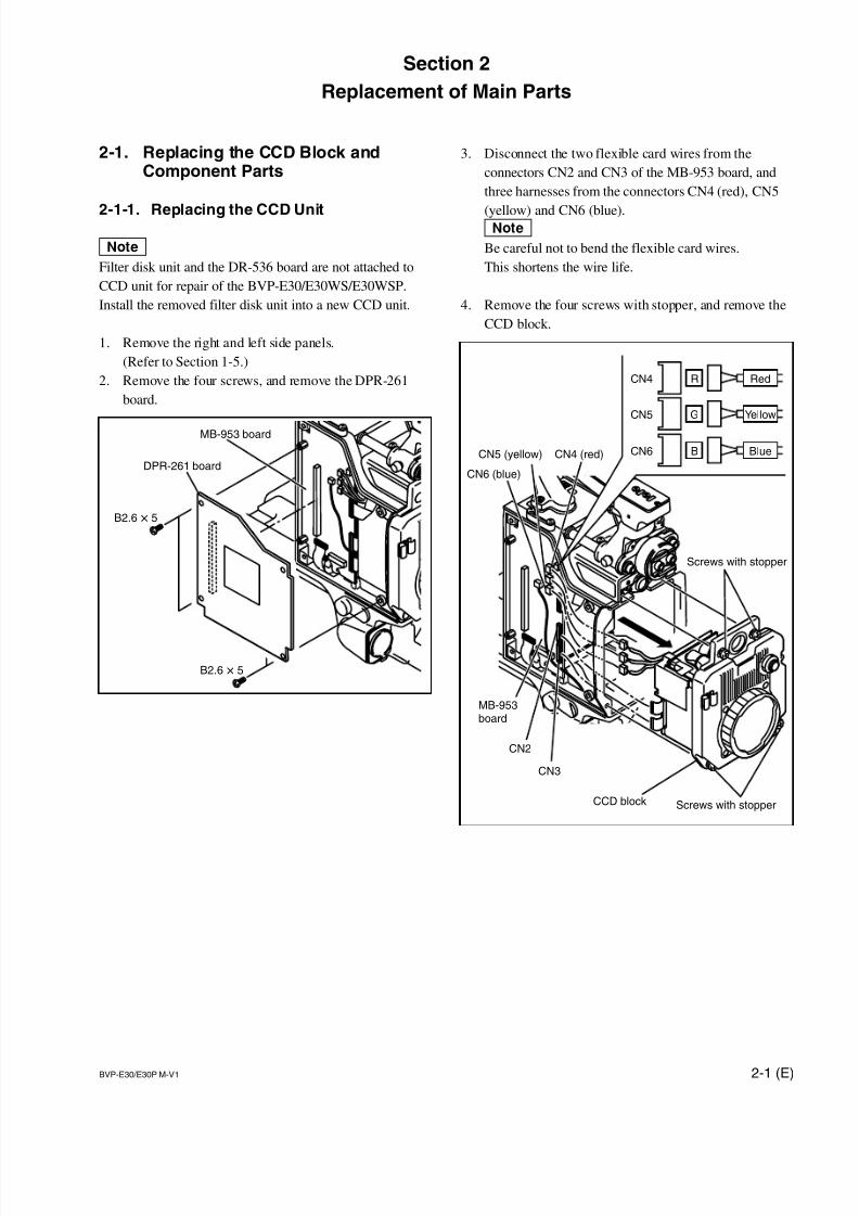
2-1. Replacing the CCD Block andComponent Parts
2-1-1. Replacing the CCD Unit
nFilter disk unit and the DR-536 board are not attached to
CCD unit for repair of the BVP-E30/E30WS/E30WSP.
Install the removed filter disk unit into a new CCD unit.
1. Remove the right and left side panels.
(Refer to Section 1-5.)
2. Remove the four screws, and remove the DPR-261
board.
3. Disconnect the two flexible card wires from the
connectors CN2 and CN3 of the MB-953 board, and
three harnesses from the connectors CN4 (red), CN5
(yellow) and CN6 (blue).nBe careful not to bend the flexible card wires.
This shortens the wire life.
4. Remove the four screws with stopper, and remove the
CCD block.
7/14/2019 Bvpe30mmi - Copy
http://slidepdf.com/reader/full/bvpe30mmi-copy 38/136
2-2 (E) BVP-E30/E30P M-V1
*1
*1
Setscrews(WP2 x 3)
Setscrew(WP3 x 3)
CC filter knob
ND filter knob
Filter knob
BVP-E30/E30WS/E30WSP
BVP-E30P
Setscrews(WP2 x 3)
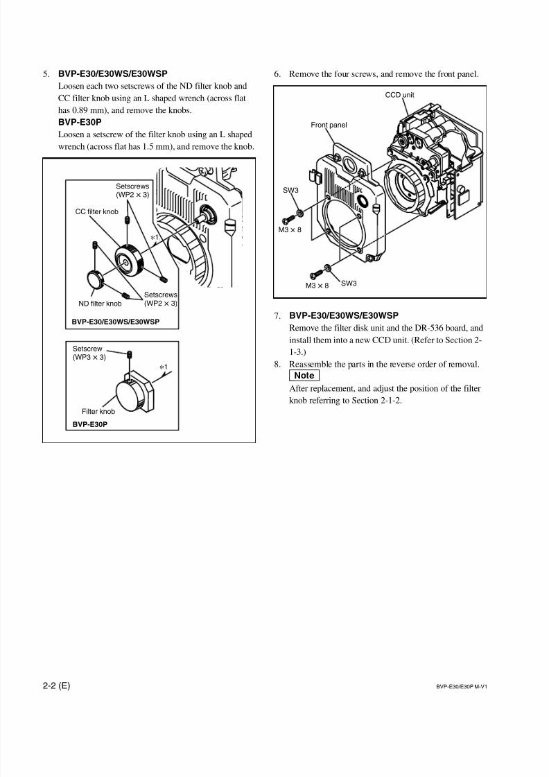
6. Remove the four screws, and remove the front panel.
7. BVP-E30/E30WS/E30WSP
Remove the filter disk unit and the DR-536 board, and
install them into a new CCD unit. (Refer to Section 2-
1-3.)
8. Reassemble the parts in the reverse order of removal.
nAfter replacement, and adjust the position of the filter
knob referring to Section 2-1-2.
CCD unit
Front panel
M3 x 8
M3 x 8
SW3
SW3
5. BVP-E30/E30WS/E30WSP
Loosen each two setscrews of the ND filter knob and
CC filter knob using an L shaped wrench (across flat
has 0.89 mm), and remove the knobs.
BVP-E30P
Loosen a setscrew of the filter knob using an L shapedwrench (across flat has 1.5 mm), and remove the knob.

7/14/2019 Bvpe30mmi - Copy
http://slidepdf.com/reader/full/bvpe30mmi-copy 39/136
2-3 (E)BVP-E30/E30P M-V1
2-1-2. Positioning Adjustment for Filter
Knob
BVP-E30/E30WS/E30WSP
1. Rotate the outer knob shaft until the cross filter can be
seen from the lens mount.2. Align the CC filter knob number A with the mark on
the front panel and tighten the two setscrews.
Tightening torque: 20 x 10 _2 N.m (2.0 kgf .cm)
3. Rotate the CC filter knob, and check that it rotates
smoothly.
4. Rotate the inner knob shaft until the clear filter
(straight through filter) can be seen from the lens
mount.
5. Align the ND filter knob number 1 with the mark on
the front panel and tighten the two setscrews.
Tightening torque: 20 x 10 _2 N.m (2.0 kgf .cm)
6. Rotate the ND filter knob, and check that it rotates
smoothly.
BVP-E30P
1. Rotate the knob shaft until the filter with the lightest
color can be seen from th lens mount.
2. Align the filter knob number 1 with the mark on the
front panel and tighten the setscrew.
Tightening torque: 50 x 10 _2
N.m (5.0 kgf .cm)
3. Rotate the filter knob, and check that it rotates smooth-
ly.
CC filter knob
ND filter knob
Mark
Setscrews(WP2 x 3)
Setscrews(WP2 x 3)
Filter knob
Setscrew(WP3 x 3)
Mark
7/14/2019 Bvpe30mmi - Copy
http://slidepdf.com/reader/full/bvpe30mmi-copy 40/136
2-4 (E) BVP-E30/E30P M-V1
4
5
1
2
3
B2.6 x 4
B2.6 x 4
B2.6 x 4
B2.6 x 4
B2.6 x 4
CN2
CN1
CN3
B2.6 x 4
K3 x 6
B2.6 x 4
CN1
CN4
PrecisionP2 x 5.0
PrecisionP2 x 5.0
Nylon rivet
Nylon rivet
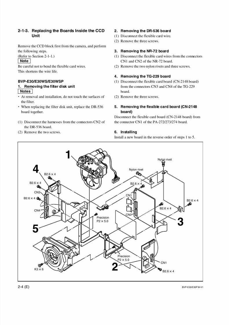
2. Removing the DR-536 board
(1) Disconnect the flexible card wire.
(2) Remove the three screws.
3. Removing the NR-72 board
(1) Disconnect the flexible card wires from the connectorsCN1 and CN2 of the NR-72 board.
(2) Remove the two nylon rivets and three screws.
4. Removing the TG-229 board
(1) Disconnect the flexible card board (CN-2148 board)
from the connectors CN3 and CN4 of the TG-229
board.
(2) Remove the three screws.
5. Removing the flexible card board (CN-2148
board)
Disconnect the flexible card board (CN-2148 board) from
the connector CN1 of the PA-272/273/274 board.
6. Installing
Install a new board in the reverse order of steps 1 to 5.
2-1-3. Replacing the Boards Inside the CCD
Unit
Remove the CCD block first from the camera, and perform
the following steps.
(Refer to Section 2-1-1.)nBe careful not to bend the flexible card wires.
This shortens the wire life.
BVP-E30/E30WS/E30WSP
1. Removing the filter disk unit
m. At removal and installation, do not touch the surfaces of
the filter.
. When replacing the filter disk unit, replace the DR-536
board together.
(1) Disconnect the harnesses from the connectors CN2 of
the DR-536 board.
(2) Remove the two screws.
7/14/2019 Bvpe30mmi - Copy
http://slidepdf.com/reader/full/bvpe30mmi-copy 41/136
2-5 (E)BVP-E30/E30P M-V1
CN3
CN4
13
2
13
2B2.6 x 4
B2.6 x 4
B2.6 x 4
B2.6 x 4
Nylon rivet
Nylon rivet
PrecisionP2 x 5.0
PrecisionP2 x 5.0
B2.6 x 4
CN1
CN2
CN4
B2.6 x 4
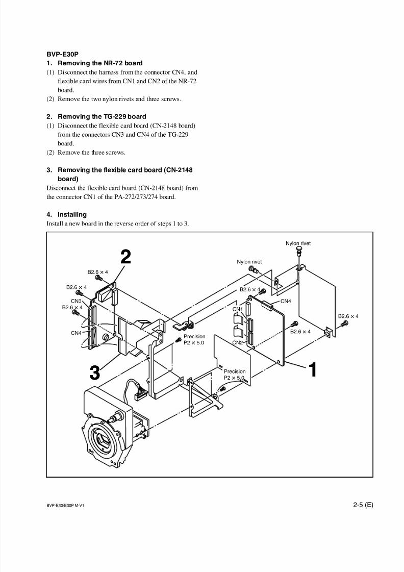
BVP-E30P
1. Removing the NR-72 board
(1) Disconnect the harness from the connector CN4, and
flexible card wires from CN1 and CN2 of the NR-72
board.
(2) Remove the two nylon rivets and three screws.
2. Removing the TG-229 board
(1) Disconnect the flexible card board (CN-2148 board)
from the connectors CN3 and CN4 of the TG-229
board.
(2) Remove the three screws.
3. Removing the flexible card board (CN-2148
board)
Disconnect the flexible card board (CN-2148 board) from
the connector CN1 of the PA-272/273/274 board.
4. Installing
Install a new board in the reverse order of steps 1 to 3.
7/14/2019 Bvpe30mmi - Copy
http://slidepdf.com/reader/full/bvpe30mmi-copy 42/136
2-6 (E) BVP-E30/E30P M-V1
ON
321 4
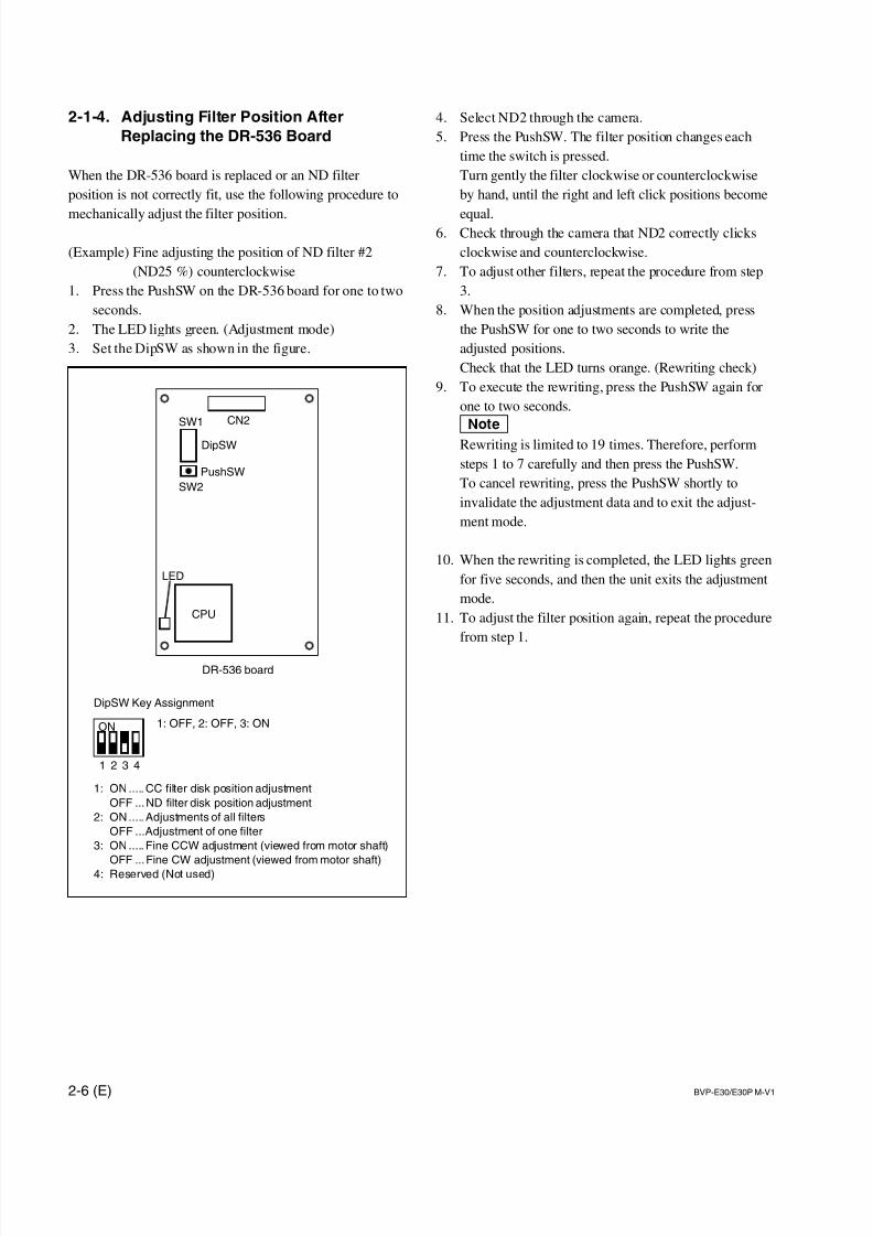
2-1-4. Adjusting Filter Position After
Replacing the DR-536 Board
When the DR-536 board is replaced or an ND filter
position is not correctly fit, use the following procedure to
mechanically adjust the filter position.
(Example) Fine adjusting the position of ND filter #2
(ND25 %) counterclockwise
1. Press the PushSW on the DR-536 board for one to two
seconds.
2. The LED lights green. (Adjustment mode)
3. Set the DipSW as shown in the figure.
4. Select ND2 through the camera.
5. Press the PushSW. The filter position changes each
time the switch is pressed.
Turn gently the filter clockwise or counterclockwise
by hand, until the right and left click positions become
equal.6. Check through the camera that ND2 correctly clicks
clockwise and counterclockwise.
7. To adjust other filters, repeat the procedure from step
3.
8. When the position adjustments are completed, press
the PushSW for one to two seconds to write the
adjusted positions.
Check that the LED turns orange. (Rewriting check)
9. To execute the rewriting, press the PushSW again for
one to two seconds.
nRewriting is limited to 19 times. Therefore, perform
steps 1 to 7 carefully and then press the PushSW.
To cancel rewriting, press the PushSW shortly to
invalidate the adjustment data and to exit the adjust-
ment mode.
10. When the rewriting is completed, the LED lights green
for five seconds, and then the unit exits the adjustment
mode.
11. To adjust the filter position again, repeat the procedure
from step 1.
1: ON..... CC filter disk position adjustment
OFF ...ND filter disk position adjustment
2: ON..... Adjustments of all filters
OFF ...Adjustment of one filter
3: ON..... Fine CCW adjustment (viewed from motor shaft)
OFF ...Fine CW adjustment (viewed from motor shaft)
4: Reserved (Not used)
DR-536 board
DipSW Key Assignment
1: OFF, 2: OFF, 3: ON
LED
DipSW
CN2SW1
SW2
PushSW
CPU
7/14/2019 Bvpe30mmi - Copy
http://slidepdf.com/reader/full/bvpe30mmi-copy 43/136
2-7 (E)BVP-E30/E30P M-V1
CN1201
Screws with stopper
Handle
SW-1075 board
Switch panel
Screw with stoper
+B2.6 x 6
+B2.6 x 6
VF connector
MB-953 board
CN1
Flexible card wire
SW-1071 board
CN801B2.6 x 5
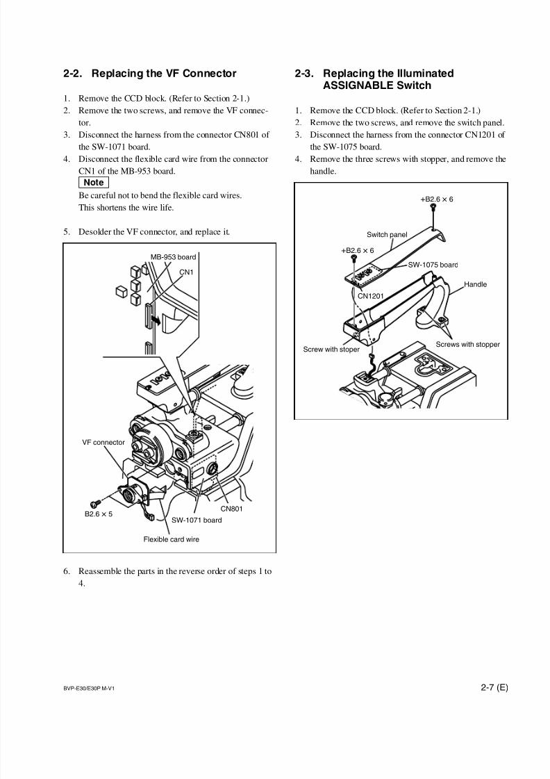
2-2. Replacing the VF Connector
1. Remove the CCD block. (Refer to Section 2-1.)
2. Remove the two screws, and remove the VF connec-
tor.
3. Disconnect the harness from the connector CN801 of the SW-1071 board.
4. Disconnect the flexible card wire from the connector
CN1 of the MB-953 board.
nBe careful not to bend the flexible card wires.
This shortens the wire life.
5. Desolder the VF connector, and replace it.
6. Reassemble the parts in the reverse order of steps 1 to
4.
2-3. Replacing the IlluminatedASSIGNABLE Switch
1. Remove the CCD block. (Refer to Section 2-1.)
2. Remove the two screws, and remove the switch panel.
3. Disconnect the harness from the connector CN1201 of the SW-1075 board.
4. Remove the three screws with stopper, and remove the
handle.

7/14/2019 Bvpe30mmi - Copy
http://slidepdf.com/reader/full/bvpe30mmi-copy 44/136
2-8 (E) BVP-E30/E30P M-V1
Bracket(SW-1071)
Handle holder
B2.6 x 5
5. Disconnect the harness from the connector CN801 of
the SW-1071 board.
6. Disconnect the harness from the connector CN18 of
the MB-953 board.
7. Remove the three screws, and remove the handle
holder.
8. Remove the two screws, and remove the bracket
(SW-1071).
9. Remove the two screws, and remove the SW-1071
board.
nWhen removing, do not lose the CC switch cover.
10. Desolder the ASSIGNABLE switch, and replace it.
11. Install the SW-1071 board to the bracket (SW-1071)
with the two screws.
m. Put the tip of the ASSIGNABLE switch into the
CC switch cover.
. Put the tip of the CC switch cover at the center of
the hole on the handle holder.
. Push the CC switch cover, and check the click sound
that the switch clicks when pushing ON/OFF.
12. Reassemble the parts in the reverse order of steps 1 to
8.nWhen installing the handle holder, make sure the
harnesses are routed properly and are not caught
between the handle holder and the chassis.
CN801
Handle holder
SW-1071 board
MB-953 board
CN18
B3 x 5
B4 x 8Bracket(SW-1071)
ASSIGNABLE switch
SW-1071 board
B2.6 x 5
CC switch cover
CC switch cover
Handle holder
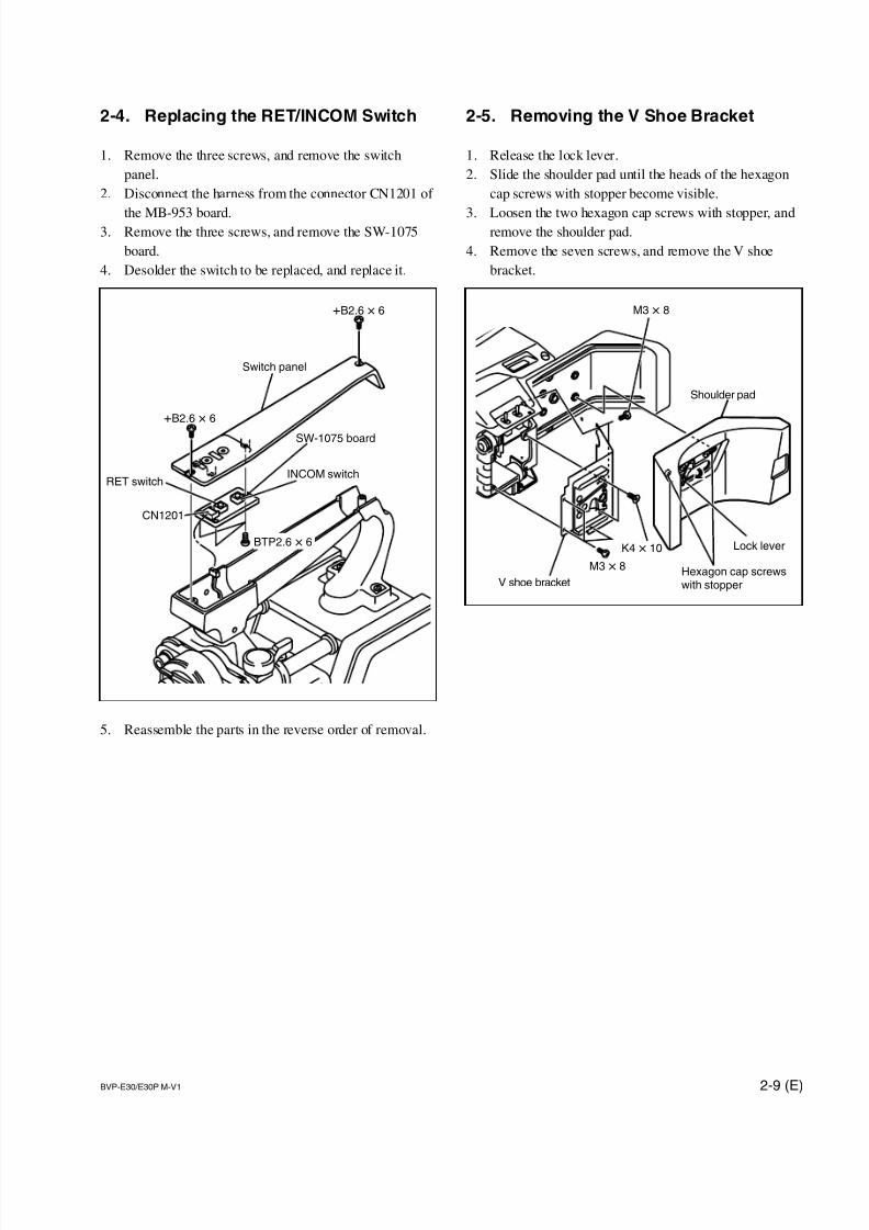
7/14/2019 Bvpe30mmi - Copy
http://slidepdf.com/reader/full/bvpe30mmi-copy 45/136
2-9 (E)BVP-E30/E30P M-V1
Shoulder pad
V shoe bracket
M3 x 8
K4 x 10
Hexagon cap screwswith stopper
M3 x 8
Lock lever
CN1201
Switch panel
SW-1075 board
INCOM switchRET switch
BTP2.6 x 6
+B2.6 x 6
+B2.6 x 6
2-4. Replacing the RET/INCOM Switch
1. Remove the three screws, and remove the switch
panel.
2. Disconnect the harness from the connector CN1201 of
the MB-953 board.3. Remove the three screws, and remove the SW-1075
board.
4. Desolder the switch to be replaced, and replace it.
5. Reassemble the parts in the reverse order of removal.
2-5. Removing the V Shoe Bracket
1. Release the lock lever.
2. Slide the shoulder pad until the heads of the hexagon
cap screws with stopper become visible.
3. Loosen the two hexagon cap screws with stopper, andremove the shoulder pad.
4. Remove the seven screws, and remove the V shoe
bracket.
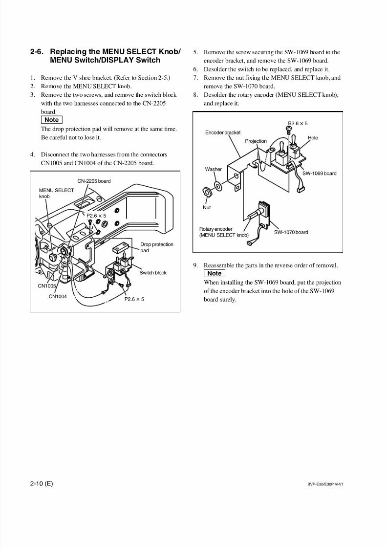
7/14/2019 Bvpe30mmi - Copy
http://slidepdf.com/reader/full/bvpe30mmi-copy 46/136
2-10 (E) BVP-E30/E30P M-V1
Drop protectionpad
Switch block
CN1005
CN1004
CN-2205 board
MENU SELECTknob
P2.6 x 5
P2.6 x 5
Nut
WasherSW-1069 board
Hole
SW-1070 boardRotary encoder(MENU SELECT knob)
Projection
Encoder bracket
B2.6 x 5
2-6. Replacing the MENU SELECT Knob/ MENU Switch/DISPLAY Switch
1. Remove the V shoe bracket. (Refer to Section 2-5.)
2. Remove the MENU SELECT knob.
3. Remove the two screws, and remove the switch block with the two harnesses connected to the CN-2205
board.
nThe drop protection pad will remove at the same time.
Be careful not to lose it.
4. Disconnect the two harnesses from the connectors
CN1005 and CN1004 of the CN-2205 board.
5. Remove the screw securing the SW-1069 board to the
encoder bracket, and remove the SW-1069 board.
6. Desolder the switch to be replaced, and replace it.
7. Remove the nut fixing the MENU SELECT knob, and
remove the SW-1070 board.
8. Desolder the rotary encoder (MENU SELECT knob),and replace it.
9. Reassemble the parts in the reverse order of removal.
nWhen installing the SW-1069 board, put the projection
of the encoder bracket into the hole of the SW-1069
board surely.
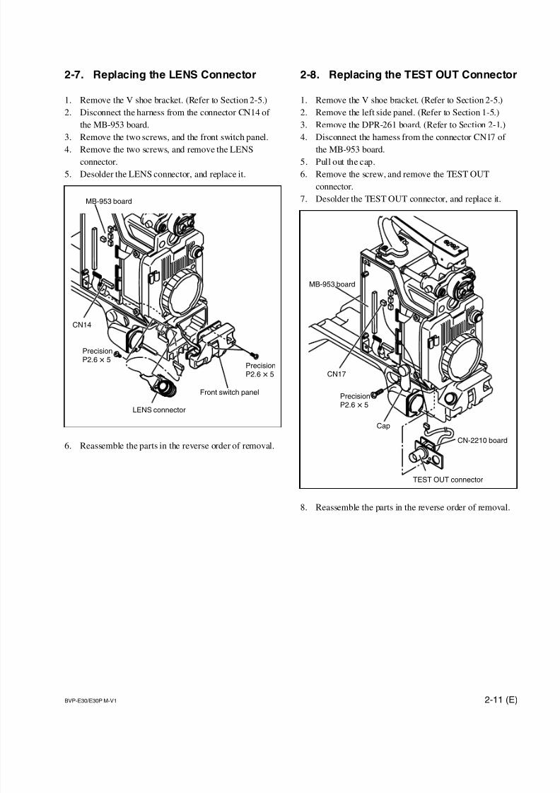
7/14/2019 Bvpe30mmi - Copy
http://slidepdf.com/reader/full/bvpe30mmi-copy 47/136
2-11 (E)BVP-E30/E30P M-V1
MB-953 board
TEST OUT connector
CN-2210 board
Cap
CN17
PrecisionP2.6 x 5
2-7. Replacing the LENS Connector
1. Remove the V shoe bracket. (Refer to Section 2-5.)
2. Disconnect the harness from the connector CN14 of
the MB-953 board.
3. Remove the two screws, and the front switch panel.4. Remove the two screws, and remove the LENS
connector.
5. Desolder the LENS connector, and replace it.
6. Reassemble the parts in the reverse order of removal.
2-8. Replacing the TEST OUT Connector
1. Remove the V shoe bracket. (Refer to Section 2-5.)
2. Remove the left side panel. (Refer to Section 1-5.)
3. Remove the DPR-261 board. (Refer to Section 2-1.)
4. Disconnect the harness from the connector CN17 of the MB-953 board.
5. Pull out the cap.
6. Remove the screw, and remove the TEST OUT
connector.
7. Desolder the TEST OUT connector, and replace it.
8. Reassemble the parts in the reverse order of removal.
MB-953 board
Front switch panel
LENS connector
CN14
PrecisionP2.6 x 5
PrecisionP2.6 x 5
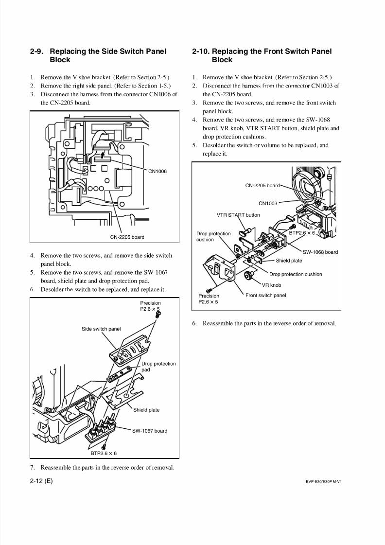
7/14/2019 Bvpe30mmi - Copy
http://slidepdf.com/reader/full/bvpe30mmi-copy 48/136
2-12 (E) BVP-E30/E30P M-V1
CN1003
CN-2205 board
SW-1068 board
Shield plate
VR knob
Front switch panel
VTR START button
Drop protectioncushion
Drop protection cushion
PrecisionP2.6 x 5
BTP2.6 x 6
2-9. Replacing the Side Switch PanelBlock
1. Remove the V shoe bracket. (Refer to Section 2-5.)
2. Remove the right side panel. (Refer to Section 1-5.)
3. Disconnect the harness from the connector CN1006 of the CN-2205 board.
4. Remove the two screws, and remove the side switch
panel block.
5. Remove the two screws, and remove the SW-1067
board, shield plate and drop protection pad.
6. Desolder the switch to be replaced, and replace it.
7. Reassemble the parts in the reverse order of removal.
2-10. Replacing the Front Switch PanelBlock
1. Remove the V shoe bracket. (Refer to Section 2-5.)
2. Disconnect the harness from the connector CN1003 of
the CN-2205 board.3. Remove the two screws, and remove the front switch
panel block.
4. Remove the two screws, and remove the SW-1068
board, VR knob, VTR START button, shield plate and
drop protection cushions.
5. Desolder the switch or volume to be replaced, and
replace it.
6. Reassemble the parts in the reverse order of removal.Side switch panel
Drop protectionpad
SW-1067 board
Shield plate
PrecisionP2.6 x 5
BTP2.6 x 6
CN-2205 board
CN1006

7/14/2019 Bvpe30mmi - Copy
http://slidepdf.com/reader/full/bvpe30mmi-copy 49/136
2-13 (E)BVP-E30/E30P M-V1
MB-953 board
DC-DC converter(RE-201 board)
P2.6 x 5
2-11. Replacing the MIC Connector
1. Remove the V shoe bracket. (Refer to Section 2-5.)
2. Disconnect the harness from the connector CN1002 of
the CN-2205 board.
3. Remove the two screws, and remove the MIC connec-tor with harness.
4. Desolder the MIC connector, and replace it.
5. Reassemble the parts in the reverse order of removal.
2-12. Replacing the DC-DC Converter
1. Remove the right side panel. (Refer to Section 1-5.)
2. Remove the two screws, and remove the DC-DC
converter (RE-201 board) while pushing it up in the
arrow direction, and replace it with a new one.
3. Reassemble the parts in the reverse order of removal.
CN-2205 board
MIC connector
CN1002
K2.6 x 6
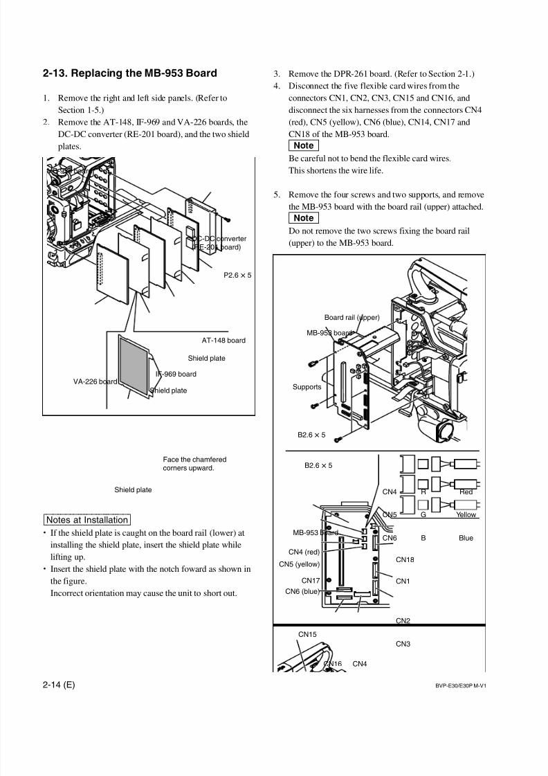
7/14/2019 Bvpe30mmi - Copy
http://slidepdf.com/reader/full/bvpe30mmi-copy 50/136
2-14 (E) BVP-E30/E30P M-V1
MB-953 board
MB-953 board
CN18
CN1
CN2
CN3
CN4CN16
CN15
CN6 (blue)
CN17
CN5 (yellow)
CN4 (red)
Board rail (upper)
B2.6 x 5
B2.6 x 5
Supports
RCN4 Red
GCN5 Yellow
BCN6 Blue
MB-953 board
VA-226 boardIF-969 board
AT-148 board
Shield plate
Shield plate
DC-DC converter(RE-201 board)
P2.6 x 5
Shield plate
Face the chamferedcorners upward.
2-13. Replacing the MB-953 Board
1. Remove the right and left side panels. (Refer to
Section 1-5.)
2. Remove the AT-148, IF-969 and VA-226 boards, the
DC-DC converter (RE-201 board), and the two shieldplates.
[Notes|at|Installation]. If the shield plate is caught on the board rail (lower) at
installing the shield plate, insert the shield plate whilelifting up.
. Insert the shield plate with the notch foward as shown in
the figure.
Incorrect orientation may cause the unit to short out.
3. Remove the DPR-261 board. (Refer to Section 2-1.)
4. Disconnect the five flexible card wires from the
connectors CN1, CN2, CN3, CN15 and CN16, and
disconnect the six harnesses from the connectors CN4
(red), CN5 (yellow), CN6 (blue), CN14, CN17 and
CN18 of the MB-953 board.nBe careful not to bend the flexible card wires.
This shortens the wire life.
5. Remove the four screws and two supports, and remove
the MB-953 board with the board rail (upper) attached.
nDo not remove the two screws fixing the board rail
(upper) to the MB-953 board.
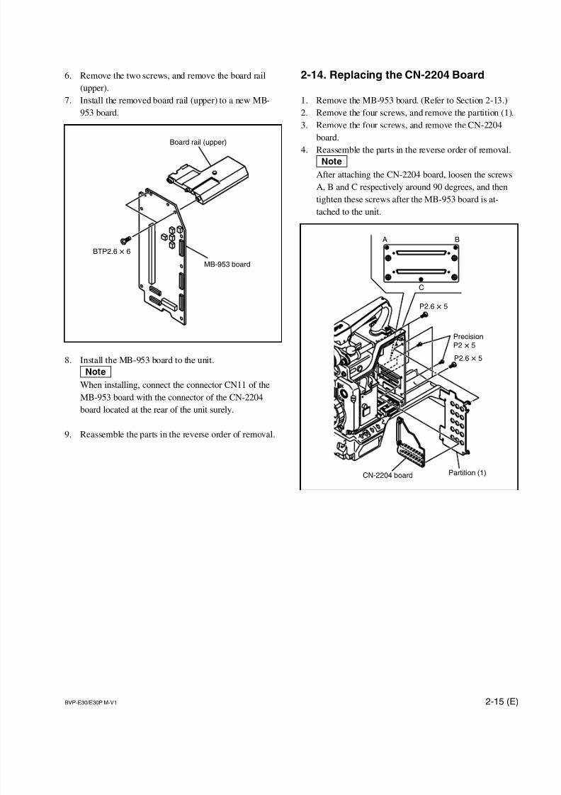
7/14/2019 Bvpe30mmi - Copy
http://slidepdf.com/reader/full/bvpe30mmi-copy 51/136
2-15 (E)BVP-E30/E30P M-V1
A B
C
CN-2204 board Partition (1)
P2.6 x 5
P2.6 x 5
PrecisionP2 x 5
6. Remove the two screws, and remove the board rail
(upper).
7. Install the removed board rail (upper) to a new MB-
953 board.
8. Install the MB-953 board to the unit.
nWhen installing, connect the connector CN11 of the
MB-953 board with the connector of the CN-2204
board located at the rear of the unit surely.
9. Reassemble the parts in the reverse order of removal.
2-14. Replacing the CN-2204 Board
1. Remove the MB-953 board. (Refer to Section 2-13.)
2. Remove the four screws, and remove the partition (1).
3. Remove the four screws, and remove the CN-2204
board.4. Reassemble the parts in the reverse order of removal.
nAfter attaching the CN-2204 board, loosen the screws
A, B and C respectively around 90 degrees, and then
tighten these screws after the MB-953 board is at-
tached to the unit.
MB-953 board
Board rail (upper)
BTP2.6 x 6
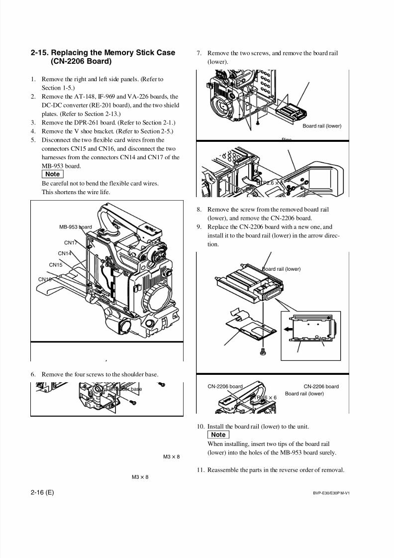
7/14/2019 Bvpe30mmi - Copy
http://slidepdf.com/reader/full/bvpe30mmi-copy 52/136
2-16 (E) BVP-E30/E30P M-V1
MB-953 board
CN15
CN17
CN14
CN16
Board rail (lower)
CN-2206 board
BTP2.6 x 6Board rail (lower)
CN-2206 board
Board rail (lower)
Pins
Pins
MB-953 board
BTP2.6 x 6
7. Remove the two screws, and remove the board rail
(lower).
8. Remove the screw from the removed board rail
(lower), and remove the CN-2206 board.
9. Replace the CN-2206 board with a new one, and
install it to the board rail (lower) in the arrow direc-
tion.
10. Install the board rail (lower) to the unit.
nWhen installing, insert two tips of the board rail
(lower) into the holes of the MB-953 board surely.
11. Reassemble the parts in the reverse order of removal.
2-15. Replacing the Memory Stick Case(CN-2206 Board)
1. Remove the right and left side panels. (Refer to
Section 1-5.)
2. Remove the AT-148, IF-969 and VA-226 boards, theDC-DC converter (RE-201 board), and the two shield
plates. (Refer to Section 2-13.)
3. Remove the DPR-261 board. (Refer to Section 2-1.)
4. Remove the V shoe bracket. (Refer to Section 2-5.)
5. Disconnect the two flexible card wires from the
connectors CN15 and CN16, and disconnect the two
harnesses from the connectors CN14 and CN17 of the
MB-953 board.
nBe careful not to bend the flexible card wires.
This shortens the wire life.
6. Remove the four screws to the shoulder base.
Shoulder base
M3 x 8
M3 x 8
7/14/2019 Bvpe30mmi - Copy
http://slidepdf.com/reader/full/bvpe30mmi-copy 53/136
BVP-E30/E30P M-V1 3-1 (E)
Section 3
Setup Menu
3-1. Setup Menu
The setup menu is used for selecting various setting values, items displayed on the viewfinder screen, the
method of displaying, and adjustments. The menu is displayed on the viewfinder screen. The menu canalso be displayed on an external monitor by connecting it to the TEST OUT connector.
Structure of Setup Menu
The setup menu is composed of the following menus.
. USER menu
. USER MENU CUSTOMIZE menu
. OPERATION menu
. PAINT menu
. MAINTENANCE menu
. FILE menu
. DIAGNOSIS menu
. SERVICE menu (Normally not displayed. For details on how to display this menu, refer to “Section 5-
1-6. SERVICE Menu”.)
nBeside above menus, the TOP menu is provided for indicating the whole configuration of the menu items.
Equipment Required
. BVP-E30/E30P : 1.5-inch viewfinder BVF-10/10CE (or black/white monitor)
BVP-E30WS/E30WSP : 2-inch viewfinder BVF-20W/20WCE (or black/white monitor)
. Connect a camera control unit CCU-550A/550AP/700A/700AP/900/900P or AC adapter AC-550/
550CE to supply power to the camera.
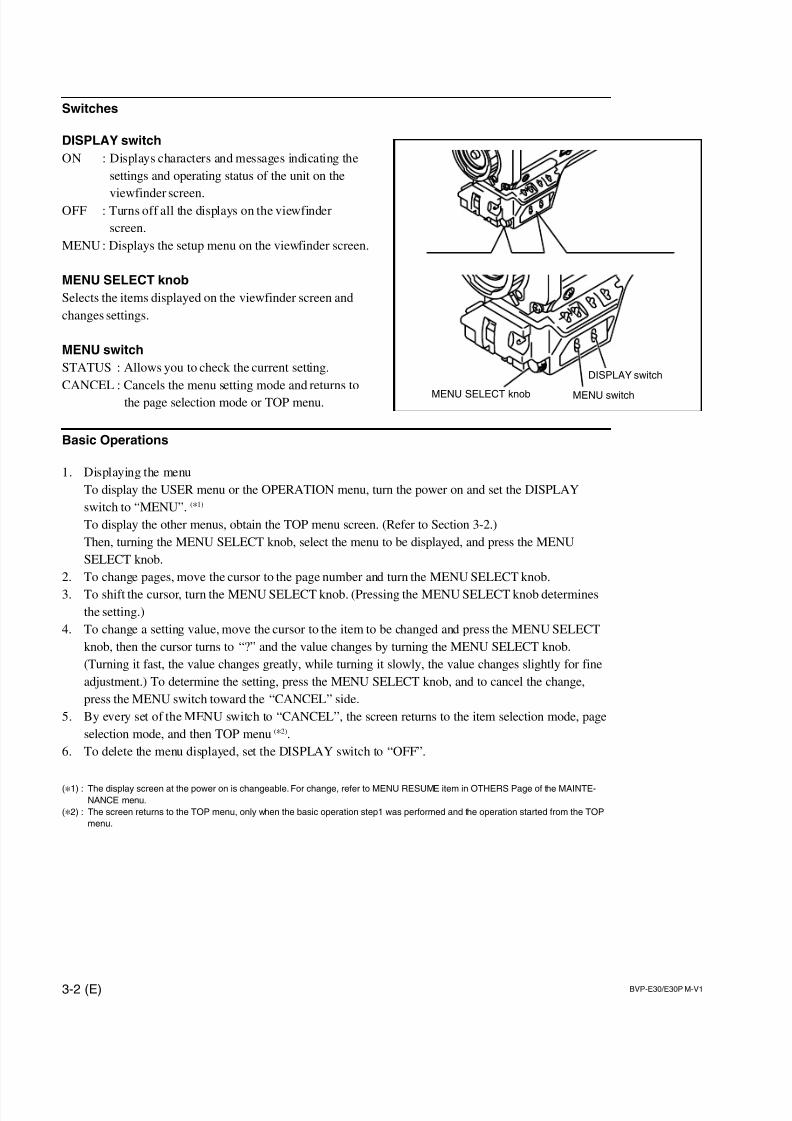
7/14/2019 Bvpe30mmi - Copy
http://slidepdf.com/reader/full/bvpe30mmi-copy 54/136
3-2 (E) BVP-E30/E30P M-V1
DISPLAY switch
MENU switchMENU SELECT knob
Switches
DISPLAY switch
ON : Displays characters and messages indicating the
settings and operating status of the unit on the
viewfinder screen.OFF : Turns off all the displays on the viewfinder
screen.
MENU : Displays the setup menu on the viewfinder screen.
MENU SELECT knob
Selects the items displayed on the viewfinder screen and
changes settings.
MENU switch
STATUS : Allows you to check the current setting.
CANCEL : Cancels the menu setting mode and returns to
the page selection mode or TOP menu.
Basic Operations
1. Displaying the menu
To display the USER menu or the OPERATION menu, turn the power on and set the DISPLAY
switch to “MENU”. (*1)
To display the other menus, obtain the TOP menu screen. (Refer to Section 3-2.)
Then, turning the MENU SELECT knob, select the menu to be displayed, and press the MENU
SELECT knob.
2. To change pages, move the cursor to the page number and turn the MENU SELECT knob.
3. To shift the cursor, turn the MENU SELECT knob. (Pressing the MENU SELECT knob determines
the setting.)
4. To change a setting value, move the cursor to the item to be changed and press the MENU SELECT
knob, then the cursor turns to “?” and the value changes by turning the MENU SELECT knob.
(Turning it fast, the value changes greatly, while turning it slowly, the value changes slightly for fine
adjustment.) To determine the setting, press the MENU SELECT knob, and to cancel the change,
press the MENU switch toward the “CANCEL” side.
5. By every set of the MENU switch to “CANCEL”, the screen returns to the item selection mode, page
selection mode, and then TOP menu (*2).
6. To delete the menu displayed, set the DISPLAY switch to “OFF”.
(*1) : The display screen at the power on is changeable. For change, refer to MENU RESUME item in OTHERS Page of the MAINTE-NANCE menu.
(*2) : The screen returns to the TOP menu, only when the basic operation step1 was performed and the operation started from the TOP
menu.
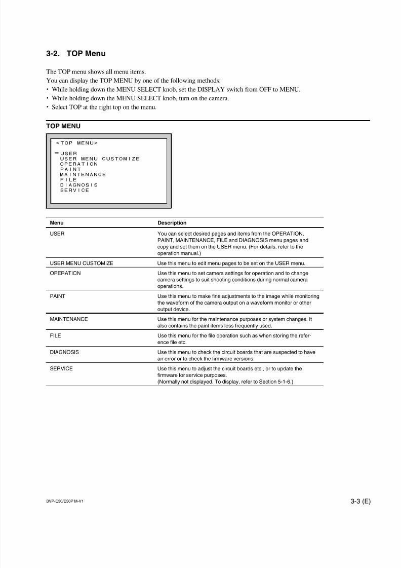
7/14/2019 Bvpe30mmi - Copy
http://slidepdf.com/reader/full/bvpe30mmi-copy 55/136
BVP-E30/E30P M-V1 3-3 (E)
<TOP MENU>
USER
USER MENU CUSTOMIZE
OPERATION
PAINT
MAINTENANCE
FILE
DIAGNOSIS
SERVICE
3-2. TOP Menu
The TOP menu shows all menu items.
You can display the TOP MENU by one of the following methods:
. While holding down the MENU SELECT knob, set the DISPLAY switch from OFF to MENU.
. While holding down the MENU SELECT knob, turn on the camera.
. Select TOP at the right top on the menu.
TOP MENU
Menu Description
USER You can select desired pages and items from the OPERATION,
PAINT, MAINTENANCE, FILE and DIAGNOSIS menu pages and
copy and set them on the USER menu. (For details, refer to the
operation manual.)
USER MENU CUSTOMIZE Use this menu to edit menu pages to be set on the USER menu.
OPERATION Use this menu to set camera settings for operation and to change
camera settings to suit shooting conditions during normal camera
operations.
PAINT Use this menu to make fine adjustments to the image while monitoringthe waveform of the camera output on a waveform monitor or other
output device.
MAINTENANCE Use this menu for the maintenance purposes or system changes. It
also contains the paint items less frequently used.
FILE Use this menu for the file operation such as when storing the refer-
ence file etc.
DIAGNOSIS Use this menu to check the circuit boards that are suspected to have
an error or to check the firmware versions.
SERVICE Use this menu to adjust the circuit boards etc., or to update the
firmware for service purposes.
(Normally not displayed. To display, refer to Section 5-1-6.)
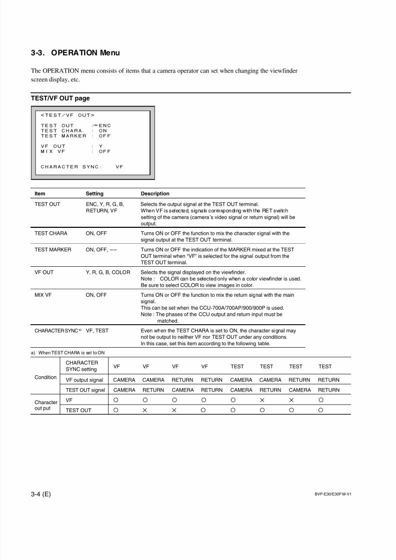
7/14/2019 Bvpe30mmi - Copy
http://slidepdf.com/reader/full/bvpe30mmi-copy 56/136
3-4 (E) BVP-E30/E30P M-V1
<TEST/VF OUT>
TEST OUT : ENC
TEST CHARA. : ON
TEST MARKER : OFF
VF OUT : Y
MIX VF : OFF
CHARACTER SYNC: VF
3-3. OPERATION Menu
The OPERATION menu consists of items that a camera operator can set when changing the viewfinder
screen display, etc.
TEST/VF OUT page
Item Setting DescriptionTEST OUT ENC, Y, R, G, B, Selects the output signal at the TEST OUT terminal.
RETURN, VF When VF is selected, signals corresponding with the RET switch
setting of the camera (camera’s video signal or return signal) will be
output.
TEST CHARA ON, OFF Turns ON or OFF the function to mix the character signal with the
signal output at the TEST OUT terminal.
TEST MARKER ON, OFF, __ Turns ON or OFF the indication of the MARKER mixed at the TEST
OUT terminal when “VF” is selected for the signal output from the
TEST OUT terminal.
VF OUT Y, R, G, B, COLOR Selects the signal displayed on the viewfinder.
Note : COLOR can be selected only when a color viewfinder is used.
Be sure to select COLOR to view images in color.
MIX VF ON, OFF Turns ON or OFF the function to mix the return signal with the mainsignal.
This can be set when the CCU-700A/700AP/900/900P is used.
Note : The phases of the CCU output and return input must be
matched.
CHARACTER SYNC a) VF, TEST Even when the TEST CHARA is set to ON, the character signal may
not be output to neither VF nor TEST OUT under any conditions.
In this case, set this item according to the following table.
a) When TEST CHARA is set to ON
CHARACTER
SYNC settingVF VF VF VF TEST TEST TEST TEST
ConditionVF output signal CAMERA CAMERA RETURN RETURN CAMERA CAMERA RETURN RETURN
TEST OUT signal CAMERA RETURN CAMERA RETURN CAMERA RETURN CAMERA RETURN
Character VF O O O O O X X Oout put TEST OUT O X X O O O O O
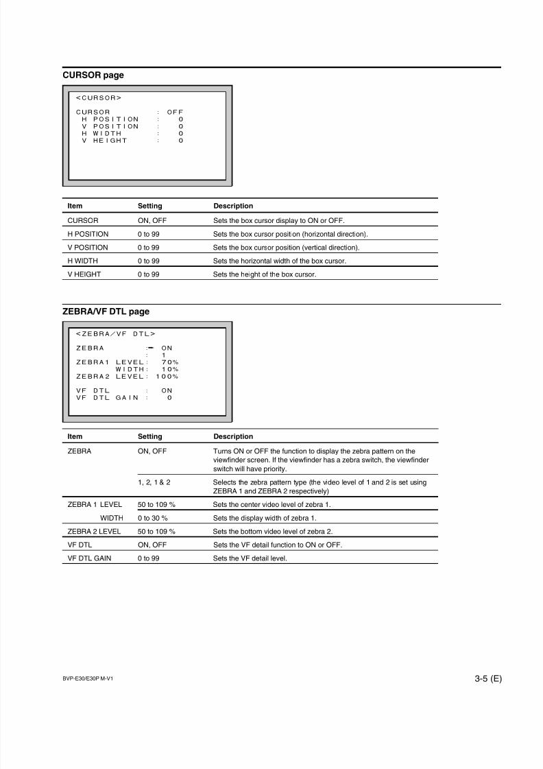
7/14/2019 Bvpe30mmi - Copy
http://slidepdf.com/reader/full/bvpe30mmi-copy 57/136
BVP-E30/E30P M-V1 3-5 (E)
<ZEBRA/VF DTL>
ZEBRA : ON
: 1
ZEBRA1 LEVEL: 70%
WIDTH: 10%
ZEBRA2 LEVEL: 100%
VF DTL : ON
VF DTL GAIN : 0
<CURSOR>
CURSOR : OFF
H POSITION : 0
V POSITION : 0
H WIDTH : 0V HEIGHT : 0
CURSOR page
Item Setting Description
CURSOR ON, OFF Sets the box cursor display to ON or OFF.
H POSITION 0 to 99 Sets the box cursor position (horizontal direction).
V POSITION 0 to 99 Sets the box cursor position (vertical direction).
H WIDTH 0 to 99 Sets the horizontal width of the box cursor.
V HEIGHT 0 to 99 Sets the height of the box cursor.
ZEBRA/VF DTL page
Item Setting Description
ZEBRA ON, OFF Turns ON or OFF the function to display the zebra pattern on the
viewfinder screen. If the viewfinder has a zebra switch, the viewfinder
switch will have priority.
1, 2, 1 & 2 Selects the zebra pattern type (the video level of 1 and 2 is set using
ZEBRA 1 and ZEBRA 2 respectively)
ZEBRA 1 LEVEL 50 to 109 % Sets the center video level of zebra 1.
WIDTH 0 to 30 % Sets the display width of zebra 1.
ZEBRA 2 LEVEL 50 to 109 % Sets the bottom video level of zebra 2.
VF DTL ON, OFF Sets the VF detail function to ON or OFF.
VF DTL GAIN 0 to 99 Sets the VF detail level.
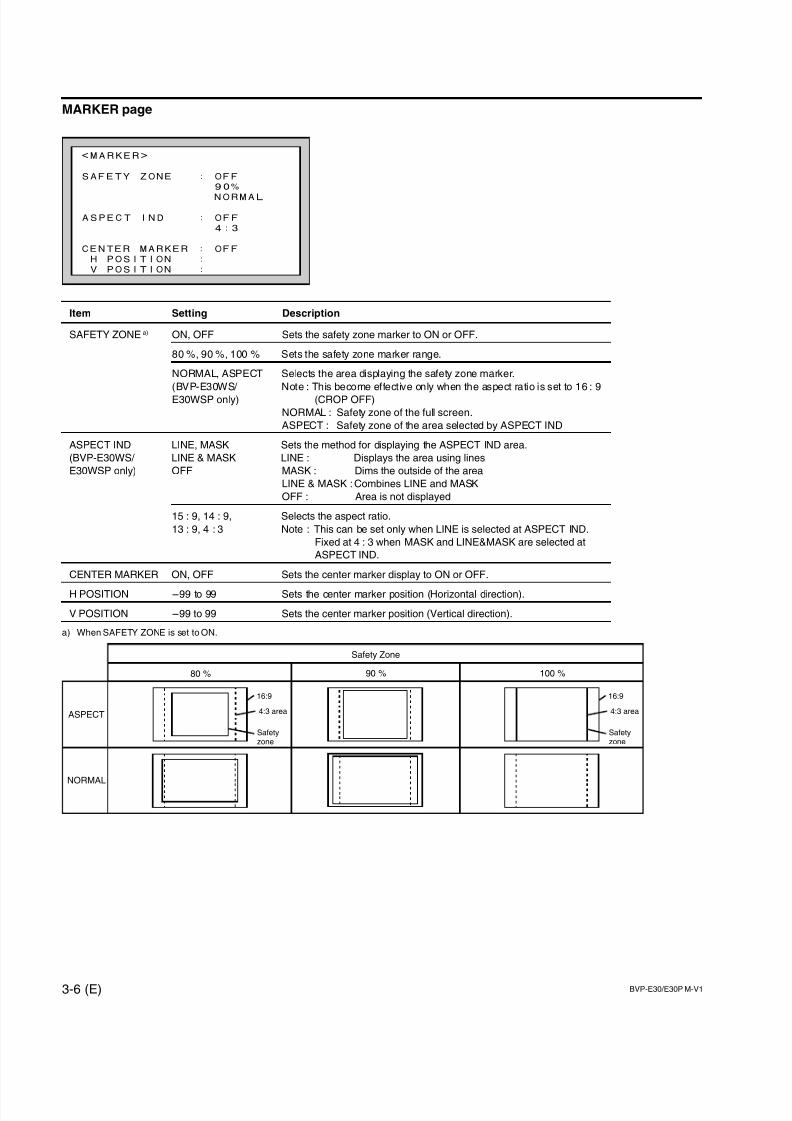
7/14/2019 Bvpe30mmi - Copy
http://slidepdf.com/reader/full/bvpe30mmi-copy 58/136
3-6 (E) BVP-E30/E30P M-V1
<MARKER>
SAFETY ZONE : OFF
90%
NORMAL
ASPECT IND : OFF
4:3
CENTER MARKER : OFF
H POSITION :
V POSITION :
MARKER page
Item Setting Description
SAFETY ZONE a) ON, OFF Sets the safety zone marker to ON or OFF.
80 %, 90 %, 100 % Sets the safety zone marker range.
NORMAL, ASPECT Selects the area displaying the safety zone marker.
(BVP-E30WS/ Note : This become effective only when the aspect ratio is set to 16 : 9
E30WSP only) (CROP OFF)
NORMAL : Safety zone of the full screen.
ASPECT : Safety zone of the area selected by ASPECT IND
ASPECT IND LINE, MASK Sets the method for displaying the ASPECT IND area.
(BVP-E30WS/ LINE & MASK LINE : Displays the area using lines
E30WSP only) OFF MASK : Dims the outside of the area
LINE & MASK : Combines LINE and MASK
OFF : Area is not displayed
15 : 9, 14 : 9, Selects the aspect ratio.
13 : 9, 4 : 3 Note : This can be set only when LINE is selected at ASPECT IND.
Fixed at 4 : 3 when MASK and LINE&MASK are selected at
ASPECT IND.
CENTER MARKER ON, OFF Sets the center marker display to ON or OFF.
H POSITION _99 to 99 Sets the center marker position (Horizontal direction).
V POSITION _99 to 99 Sets the center marker position (Vertical direction).
a) When SAFETY ZONE is set to ON.
16:9
4:3 area
Safetyzone
80 % 90 % 100 %
ASPECT
Safety Zone
NORMAL
16:9
4:3 area
Safetyzone
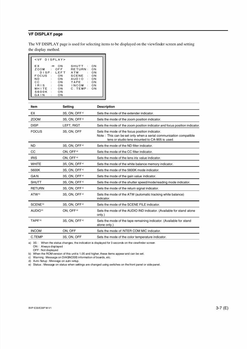
7/14/2019 Bvpe30mmi - Copy
http://slidepdf.com/reader/full/bvpe30mmi-copy 59/136
BVP-E30/E30P M-V1 3-7 (E)
<VF DISPLAY>
EX : ON SHUTT : ON
ZOOM : OFF RETURN: ON
DISP: LEFT ATW : ON
FOCUS : ON SCENE : ON
ND : ON AUDIO : ON
CC : ON TAPE : ON
IRIS : ON INCOM : ON
WHITE : ON C.TEMP: ON
5600K : ON
GAIN : ON
VF DISPLAY page
The VF DISPLAY page is used for selecting items to be displayed on the viewfinder screen and setting
the display method.
Item Setting Description
EX 3S, ON, OFF a) Sets the mode of the extender indicator.
ZOOM 3S, ON, OFF a) Sets the mode of the zoom position indicator.
DISP LEFT, RIGT Sets the mode of the zoom position indicator and focus position indicator.
FOCUS 3S, ON, OFF Sets the mode of the focus position indicator.
Note : This can be set only when a serial communication compatible
lens or studio lens mounted to CA-905 is used.
ND 3S, ON, OFF a) Sets the mode of the ND filter indicator.
CC ON, OFF a) Sets the mode of the CC filter indicator.
IRIS ON, OFF a) Sets the mode of the lens iris value indicator.
WHITE 3S, ON, OFF a) Sets the mode of the white balance memory indicator.
5600K 3S, ON, OFF a) Sets the mode of the 5600K mode indicator.
GAIN 3S, ON, OFF a) Sets the mode of the gain value indicator.
SHUTT 3S, ON, OFFa)
Sets the mode of the shutter speed/mode/reading mode indicator.RETURN 3S, ON, OFF a) Sets the mode of the return signal indicator.
ATW b) 3S, ON, OFF a) Sets the mode of the ATW (automatic tracking white balance)
indicator.
SCENE b) 3S, ON, OFF a) Sets the mode of the SCENE FILE indicator.
AUDIO b) ON, OFF a) Sets the mode of the AUDIO IND indicator. (Available for stand alone
only.)
TAPE b) 3S, ON, OFF a) Sets the mode of the tape remaining indicator. (Available for stand
alone only.)
INCOM ON, OFF Sets the mode of INTER COM MIC indicator.
C.TEMP 3S, ON, OFF Sets the mode of the color temperature indicator.
a) 3S : When the status changes, the indication is displayed for 3 seconds on the viewfinder screen
ON : Always displayed
OFF : Not displayed
b) When the ROM version of this unit is 1.05 and higher, these items appear and can be set.
c) Warning : Message on DIAGNOSIS information of boards, etc.
d) Auto Setup : Message on auto setup.
e) Status : Message on status when settings are changed using switches on the front panel or side panel.
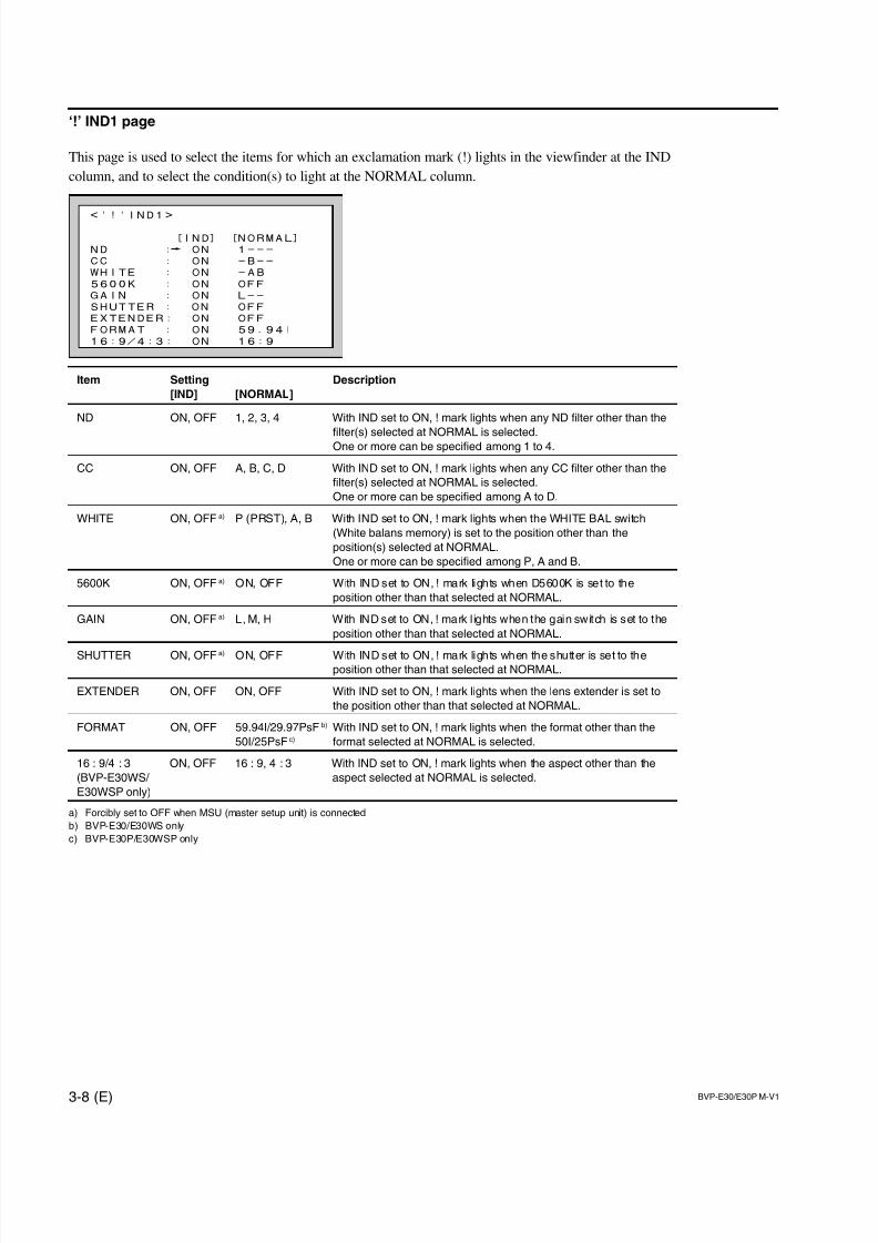
7/14/2019 Bvpe30mmi - Copy
http://slidepdf.com/reader/full/bvpe30mmi-copy 60/136
3-8 (E) BVP-E30/E30P M-V1
<'!'IND1>
[IND] [NORMAL]
ND : ON 1---
CC : ON -B--
WHITE : ON -AB
5600K : ON OFF
GAIN : ON L--
SHUTTER : ON OFF
EXTENDER: ON OFF
FORMAT : ON 59.94I
16:9/4:3: ON 16:9
‘!’ IND1 page
This page is used to select the items for which an exclamation mark (!) lights in the viewfinder at the IND
column, and to select the condition(s) to light at the NORMAL column.
Item Setting Description
[IND] [NORMAL]
ND ON, OFF 1, 2, 3, 4 With IND set to ON, ! mark lights when any ND filter other than the
filter(s) selected at NORMAL is selected.One or more can be specified among 1 to 4.
CC ON, OFF A, B, C, D With IND set to ON, ! mark lights when any CC filter other than the
filter(s) selected at NORMAL is selected.
One or more can be specified among A to D.
WHITE ON, OFF a) P (PRST), A, B With IND set to ON, ! mark lights when the WHITE BAL switch
(White balans memory) is set to the position other than the
position(s) selected at NORMAL.
One or more can be specified among P, A and B.
5600K ON, OFF a) ON, OFF With IND set to ON, ! mark lights when D5600K is set to the
position other than that selected at NORMAL.
GAIN ON, OFF a) L, M, H With IND set to ON, ! mark l ights when the gain switch is set to the
position other than that selected at NORMAL.
SHUTTER ON, OFF a) ON, OFF With IND set to ON, ! mark lights when the shutter is set to theposition other than that selected at NORMAL.
EXTENDER ON, OFF ON, OFF With IND set to ON, ! mark lights when the lens extender is set to
the position other than that selected at NORMAL.
FORMAT ON, OFF 59.94I/29.97PsF b) With IND set to ON, ! mark lights when the format other than the
50I/25PsF c) format selected at NORMAL is selected.
16 : 9/4 : 3 ON, OFF 16 : 9, 4 : 3 With IND set to ON, ! mark lights when the aspect other than the
(BVP-E30WS/ aspect selected at NORMAL is selected.
E30WSP only)
a) Forcibly set to OFF when MSU (master setup unit) is connected
b) BVP-E30/E30WS only
c) BVP-E30P/E30WSP only
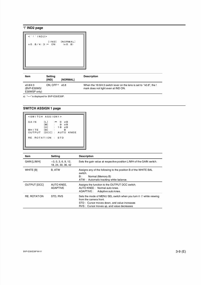
7/14/2019 Bvpe30mmi - Copy
http://slidepdf.com/reader/full/bvpe30mmi-copy 61/136
BVP-E30/E30P M-V1 3-9 (E)
<'!'IND2>
[IND] [NORMAL]
x0.8/4:3: ON (x0.8)
<SWITCH ASSIGN1>
GAIN [L] : 0 dB
[M] : 9 dB
[H] : 18 dB
WHITE [B] : B
OUTPUT [DCC]: AUTO KNEE
RE.ROTATION : STD
‘!’ IND2 page
Item Setting Description
[IND] [NORMAL]
x0.8/4:3 ON, OFF a) x0.8 When the 16:9/4:3 switch lever on the lens is set to “x0.8”, the !
(BVP-E30WS/ mark does not light even at IND ON.
E30WSP only)
a) “__” is displayed for BVP-E30/E30P.
SWITCH ASSIGN 1 page
Item Setting Description
GAIN [L/M/H] _3, 0, 3, 6, 9, 12, Sets the gain value at respective position L/M/H of the GAIN switch.
18, 24, 30, 36, 42
WHITE [B] B, ATW Assigns any of the following to the position B of the WHITE BAL
switch.
B : Normal (Memory B)
ATW : Automatic tracking white balance.
OUTPUT [DCC] AUTO KNEE, Assigns the function to the OUTPUT DCC switch.
ADAPTIVE AUTO KNEE : Normal auto knee.
ADAPTIVE : Adaptive auto knee.
RE. ROTATION STD, RVS Sets the mode of MENU SEL switch when you turn it 3 while viewing
from the camera front.STD : Cursor moves down, and value increases
RVS : Cursor moves up, and value decreases
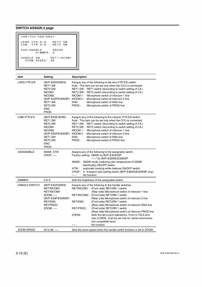
7/14/2019 Bvpe30mmi - Copy
http://slidepdf.com/reader/full/bvpe30mmi-copy 62/136
3-10 (E) BVP-E30/E30P M-V1
<SWITCH ASSIGN2>
LENS VTR S/S : RET2 SW
CAM VTR S/S : RET2 SW
ASSIGNABLE : 5600KDIMMER: 5
HANDLE SW : RET/INCOM1
ZOOM SPEED: 50
SWITCH ASSIGN 2 page
Item Setting Description
LENS VTR S/S (BVP-E30/E30WS) Assigns any of the following to the lens VTR S/S switch.
RET1 SW Note : This item can be set only when the CCU is connected.
RET2 SW RET1 SW : RET1 switch (According to switch setting of CA.)
INCOM1 RET2 SW : RET2 switch (According to switch setting of CA.)
INCOM2 INCOM 1 : Microphone switch of intercom 1 line
(BVP-E30P/E30WSP) INCOM 2 : Microphone switch of intercom 2 line
RET1 SW ENG : Microphone switch of ENG line
RET2 SW PROD : Microphone switch of PROD line
ENG
PROD
CAM VTR S/S (BVP-E30/E30WS) Assigns any of the following to the camera VTR S/S switch.
RET1 SW Note : This item can be set only when the CCU is connected.
RET2 SW RET1 SW : RET1 switch (According to switch setting of CA.)
INCOM1 RET2 SW : RET2 switch (According to switch setting of CA.)
INCOM2 INCOM 1 : Microphone switch of intercom 1 line
(BVP-E30P/E30WSP) INCOM 2 : Microphone switch of intercom 2 line
RET1 SW ENG : Microphone switch of ENG line
RET2 SW PROD : Microphone switch of PROD line
ENG
PROD
ASSIGNABLE 5600K, ATW Assigns any of the following to the assignable switch.
CROP, __ Factory setting : 5600K for BVP-E30/E30P
“__” for BVP-E30WS/E30WSP
5600K : 5600K mode (realizing color temperature of 5600K
electrically) ON/OFF switch
ATW : automatic tracking white balance ON/OFF switch
CROP : 4 : 3 aspect ratio setting switch (BVP-E30WS/E30WSP only)
__ : No function.
DIMMER 0 to 9 Sets the brightness of the assignable switch.
HANDLE SWITCH (BVP-E30/E30WS) Assigns any of the following to the handle switches.
RET/INCOM1 RET/INCOM1 : (Front side) RETURN 1 switch
RET/INCOM2 (Rear side) Microphone switch of intercom 1 line
ZOOM, __ RET/INCOM2 : (Front side) RETURN 1 switch
(BVP-E30P/E30WSP) (Rear side) Microphone switch of intercom 2 line
RET/ENG RET/ENG : (Front side) RETURN 1 switchRET/PROD (Rear side) Microphone switch of intercom ENG line
ZOOM, __ RET/PROD : (Front side) RETURN 1 switch
(Rear side) Microphone switch of intercom PROD line
ZOOM : Sets the lens zoom operations. Front is TELE and
rear is WIDE. (Can be set only for serial communica-
tion compatible lens)
__ : No function
ZOOM SPEED 00 to 99, __ Sets the zoom speed when the handle switch function is set to ZOOM.
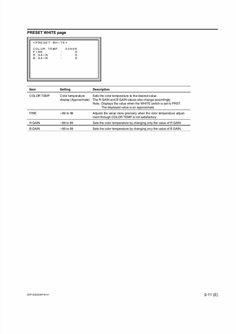
7/14/2019 Bvpe30mmi - Copy
http://slidepdf.com/reader/full/bvpe30mmi-copy 63/136
BVP-E30/E30P M-V1 3-11 (E)
<PRESET WHITE>
COLOR TEMP : 3200K
FINE : 0
R GAIN : 0
B GAIN : 0
PRESET WHITE page
Item Setting Description
COLOR TEMP Color temperature Sets the color temperature to the desired value.
display (Approximate) The R GAIN and B GAIN values also change accordingly.
Note : Displays the value when the WHITE switch is set to PRST.
The displayed value is an approximate.
FINE _99 to 99 Adjusts the value more precisely when the color temperature adjust-
ment through COLOR TEMP is not satisfactory
R GAIN _99 to 99 Sets the color temperature by changing only the value of R GAIN.
B GAIN _99 to 99 Sets the color temperature by changing only the value of B GAIN.
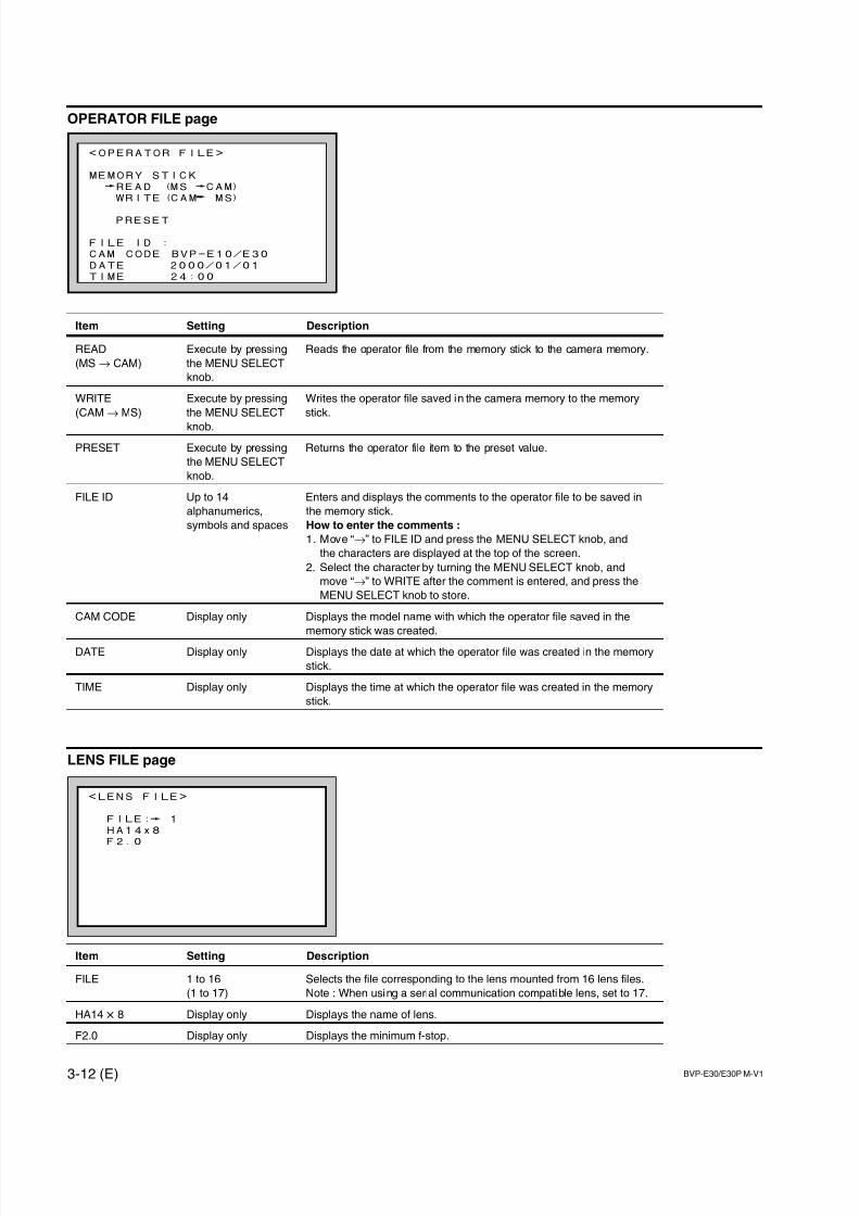
7/14/2019 Bvpe30mmi - Copy
http://slidepdf.com/reader/full/bvpe30mmi-copy 64/136
3-12 (E) BVP-E30/E30P M-V1
<OPERATOR FILE>
MEMORY STICK
READ (MS CAM)
WRITE(CAM MS)
PRESET
FILE ID :
CAM CODE BVP-E10/E30
DATE 2000/01/01
TIME 24:00
<LENS FILE>
FILE: 1
HA14x8
F2.0
OPERATOR FILE page
Item Setting Description
READ Execute by pressing Reads the operator file from the memory stick to the camera memory.
(MS→ CAM) the MENU SELECT
knob.
WRITE Execute by pressing Writes the operator file saved in the camera memory to the memory
(CAM→ MS) the MENU SELECT stick.
knob.
PRESET Execute by pressing Returns the operator file item to the preset value.
the MENU SELECT
knob.
FILE ID Up to 14 Enters and displays the comments to the operator file to be saved in
alphanumerics, the memory stick.
symbols and spaces How to enter the comments :
1. Move “→” to FILE ID and press the MENU SELECT knob, and
the characters are displayed at the top of the screen.
2. Select the character by turning the MENU SELECT knob, and
move “→” to WRITE after the comment is entered, and press the
MENU SELECT knob to store.
CAM CODE Display only Displays the model name with which the operator file saved in the
memory stick was created.
DATE Display only Displays the date at which the operator file was created in the memory
stick.
TIME Display only Displays the time at which the operator file was created in the memory
stick.
LENS FILE page
Item Setting Description
FILE 1 to 16 Selects the file corresponding to the lens mounted from 16 lens files.
(1 to 17) Note : When using a serial communication compatible lens, set to 17.
HA14 x 8 Display only Displays the name of lens.
F2.0 Display only Displays the minimum f-stop.
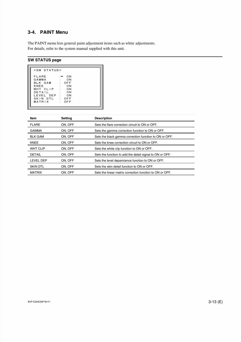
7/14/2019 Bvpe30mmi - Copy
http://slidepdf.com/reader/full/bvpe30mmi-copy 65/136
BVP-E30/E30P M-V1 3-13 (E)
<SW STATUS>
FLARE : ON
GAMMA : ON
BLK GAM : OFF
KNEE : ON
WHT CLIP : ON
DETAIL : ON
LEVEL DEP : ON
SKIN DTL : OFF
MATRIX : OFF
3-4. PAINT Menu
The PAINT menu lists general paint adjustment items such as white adjustments.
For details, refer to the system manual supplied with this unit.
SW STATUS page
Item Setting DescriptionFLARE ON, OFF Sets the flare correction circuit to ON or OFF.
GAMMA ON, OFF Sets the gamma correction function to ON or OFF.
BLK GAM ON, OFF Sets the black gamma correction function to ON or OFF.
KNEE ON, OFF Sets the knee correction circuit to ON or OFF.
WHT CLIP ON, OFF Sets the white clip function to ON or OFF.
DETAIL ON, OFF Sets the function to add the detail signal to ON or OFF.
LEVEL DEP ON, OFF Sets the level dependence function to ON or OFF.
SKIN DTL ON, OFF Sets the skin detail function to ON or OFF.
MATRIX ON, OFF Sets the linear matrix correction function to ON or OFF.
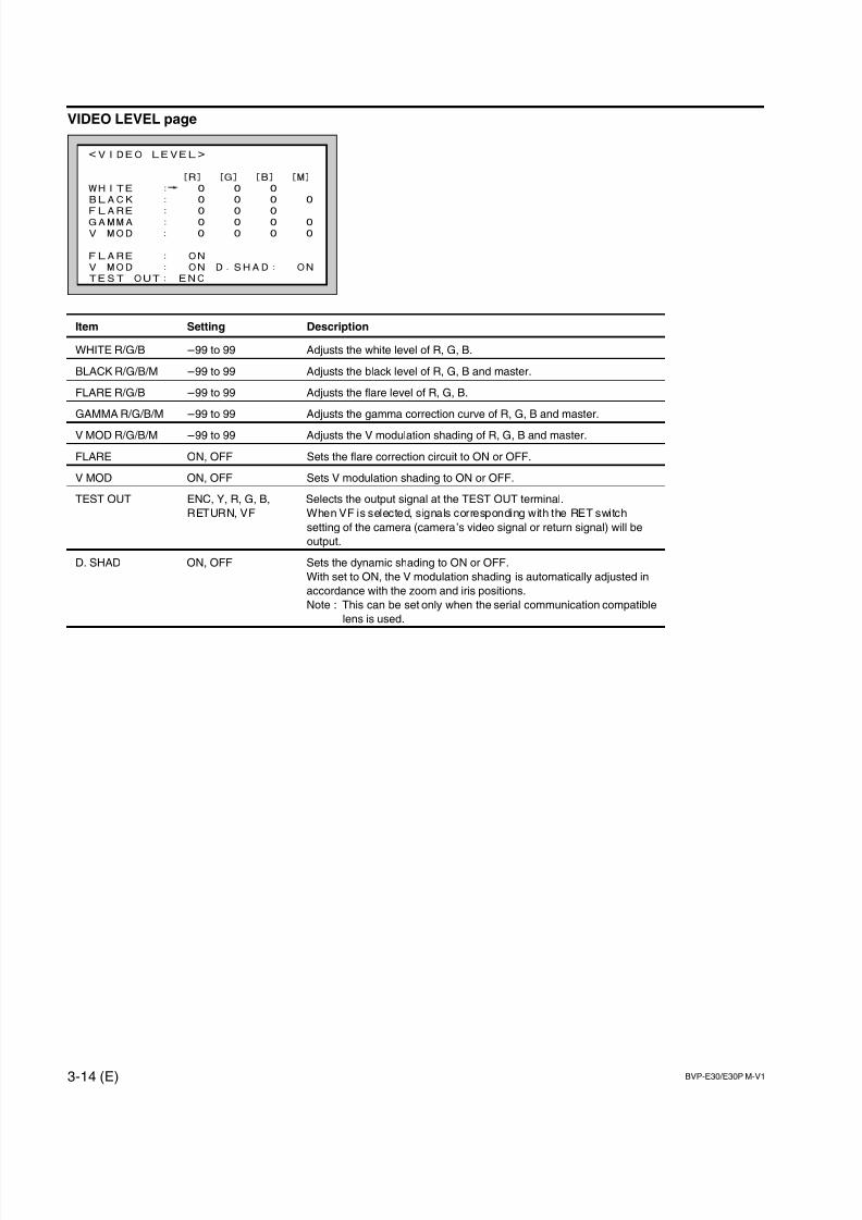
7/14/2019 Bvpe30mmi - Copy
http://slidepdf.com/reader/full/bvpe30mmi-copy 66/136
3-14 (E) BVP-E30/E30P M-V1
<VIDEO LEVEL>
[R] [G] [B] [M]
WHITE : 0 0 0
BLACK : 0 0 0 0
FLARE : 0 0 0GAMMA : 0 0 0 0
V MOD : 0 0 0 0
FLARE : ON
V MOD : ON D.SHAD: ON
TEST OUT: ENC
VIDEO LEVEL page
Item Setting Description
WHITE R/G/B _99 to 99 Adjusts the white level of R, G, B.
BLACK R/G/B/M _99 to 99 Adjusts the black level of R, G, B and master.
FLARE R/G/B _99 to 99 Adjusts the flare level of R, G, B.
GAMMA R/G/B/M _99 to 99 Adjusts the gamma correction curve of R, G, B and master.
V MOD R/G/B/M _99 to 99 Adjusts the V modulation shading of R, G, B and master.
FLARE ON, OFF Sets the flare correction circuit to ON or OFF.
V MOD ON, OFF Sets V modulation shading to ON or OFF.
TEST OUT ENC, Y, R, G, B, Selects the output signal at the TEST OUT terminal.
RETURN, VF When VF is selected, signals corresponding with the RET switch
setting of the camera (camera’s video signal or return signal) will be
output.
D. SHAD ON, OFF Sets the dynamic shading to ON or OFF.
With set to ON, the V modulation shading is automatically adjusted in
accordance with the zoom and iris positions.
Note : This can be set only when the serial communication compatible
lens is used.
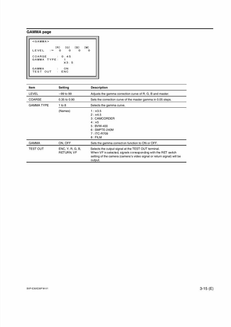
7/14/2019 Bvpe30mmi - Copy
http://slidepdf.com/reader/full/bvpe30mmi-copy 67/136
BVP-E30/E30P M-V1 3-15 (E)
<GAMMA>
[R] [G] [B] [M]
LEVEL : 0 0 0 0
COARSE : 0.45GAMMA TYPE: 1
x3.5
GAMMA : ON
TEST OUT : ENC
GAMMA page
Item Setting Description
LEVEL _99 to 99 Adjusts the gamma correction curve of R, G, B and master.
COARSE 0.35 to 0.90 Sets the correction curve of the master gamma in 0.05 steps.
GAMMA TYPE 1 to 8 Selects the gamma curve.
(Names) 1 : x3.5
2 : x4.53 : CAMCORDER
4 : x5
5 : BVW-400
6 : SMPTE-240M
7 : ITC-R709
8 : FILM
GAMMA ON, OFF Sets the gamma correction function to ON or OFF.
TEST OUT ENC, Y, R, G, B, Selects the output signal at the TEST OUT terminal.
RETURN, VF When VF is selected, signals corresponding with the RET switch
setting of the camera (camera’s video signal or return signal) will be
output.
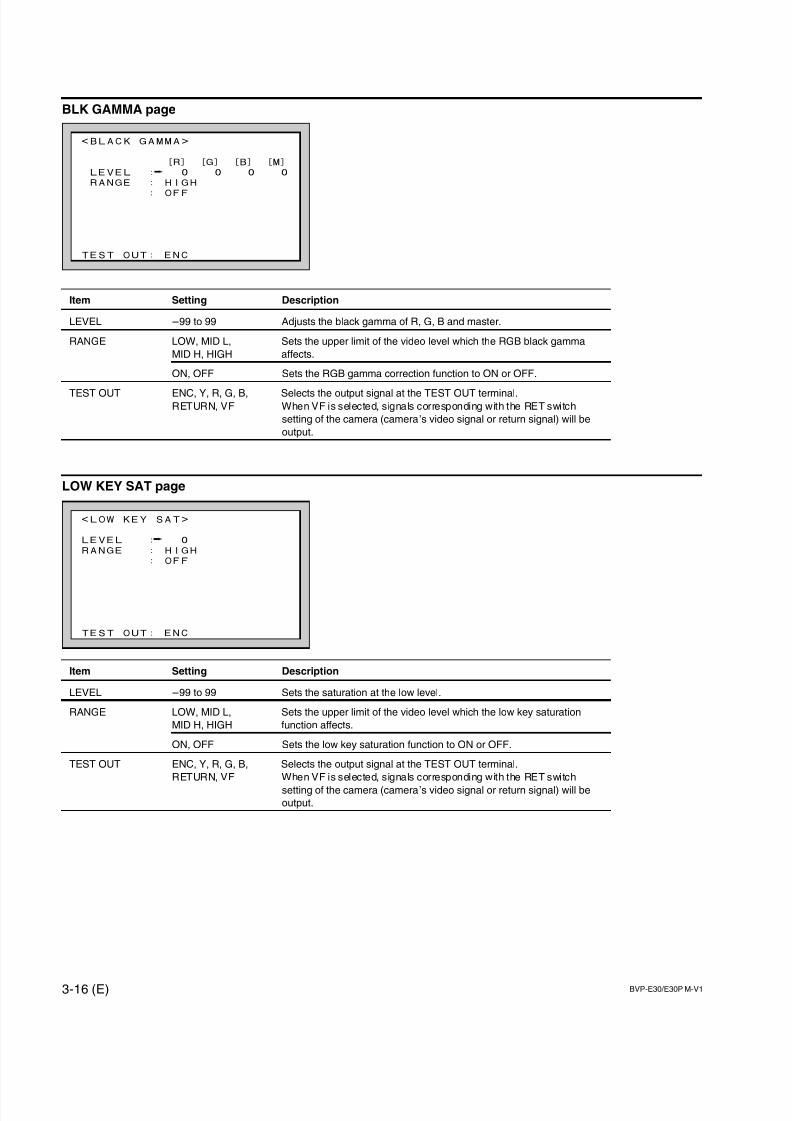
7/14/2019 Bvpe30mmi - Copy
http://slidepdf.com/reader/full/bvpe30mmi-copy 68/136
3-16 (E) BVP-E30/E30P M-V1
<LOW KEY SAT>
LEVEL : 0
RANGE : HIGH
: OFF
TEST OUT: ENC
<BLACK GAMMA>
[R] [G] [B] [M]
LEVEL : 0 0 0 0
RANGE : HIGH
: OFF
TEST OUT: ENC
BLK GAMMA page
Item Setting Description
LEVEL _99 to 99 Adjusts the black gamma of R, G, B and master.
RANGE LOW, MID L, Sets the upper limit of the video level which the RGB black gamma
MID H, HIGH affects.
ON, OFF Sets the RGB gamma correction function to ON or OFF.
TEST OUT ENC, Y, R, G, B, Selects the output signal at the TEST OUT terminal.RETURN, VF When VF is selected, signals corresponding with the RET switch
setting of the camera (camera’s video signal or return signal) will be
output.
LOW KEY SAT page
Item Setting Description
LEVEL _99 to 99 Sets the saturation at the low level.
RANGE LOW, MID L, Sets the upper limit of the video level which the low key saturation
MID H, HIGH function affects.
ON, OFF Sets the low key saturation function to ON or OFF.
TEST OUT ENC, Y, R, G, B, Selects the output signal at the TEST OUT terminal.
RETURN, VF When VF is selected, signals corresponding with the RET switch
setting of the camera (camera’s video signal or return signal) will be
output.
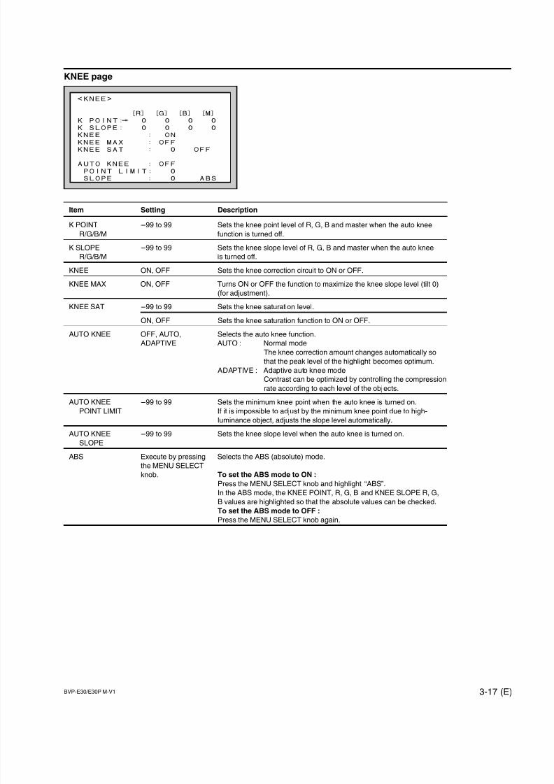
7/14/2019 Bvpe30mmi - Copy
http://slidepdf.com/reader/full/bvpe30mmi-copy 69/136
BVP-E30/E30P M-V1 3-17 (E)
<KNEE>
[R] [G] [B] [M]
K POINT: 0 0 0 0
K SLOPE: 0 0 0 0
KNEE : ONKNEE MAX : OFF
KNEE SAT : 0 OFF
AUTO KNEE : OFF
POINT LIMIT: 0
SLOPE : 0 ABS
KNEE page
Item Setting Description
K POINT _99 to 99 Sets the knee point level of R, G, B and master when the auto knee
R/G/B/M function is turned off.
K SLOPE _99 to 99 Sets the knee slope level of R, G, B and master when the auto knee
R/G/B/M is turned off.
KNEE ON, OFF Sets the knee correction circuit to ON or OFF.
KNEE MAX ON, OFF Turns ON or OFF the function to maximize the knee slope level (tilt 0)
(for adjustment).
KNEE SAT _99 to 99 Sets the knee saturation level.
ON, OFF Sets the knee saturation function to ON or OFF.
AUTO KNEE OFF, AUTO, Selects the auto knee function.
ADAPTIVE AUTO : Normal mode
The knee correction amount changes automatically so
that the peak level of the highlight becomes optimum.
ADAPTIVE : Adaptive auto knee mode
Contrast can be optimized by controlling the compression
rate according to each level of the objects.
AUTO KNEE _99 to 99 Sets the minimum knee point when the auto knee is turned on.
POINT LIMIT If it is impossible to adjust by the minimum knee point due to high-luminance object, adjusts the slope level automatically.
AUTO KNEE _99 to 99 Sets the knee slope level when the auto knee is turned on.
SLOPE
ABS Execute by pressing Selects the ABS (absolute) mode.
the MENU SELECT
knob. To set the ABS mode to ON :
Press the MENU SELECT knob and highlight “ABS”.
In the ABS mode, the KNEE POINT, R, G, B and KNEE SLOPE R, G,
B values are highlighted so that the absolute values can be checked.
To set the ABS mode to OFF :
Press the MENU SELECT knob again.
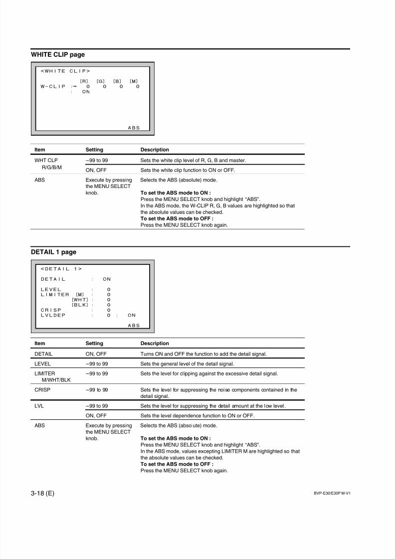
7/14/2019 Bvpe30mmi - Copy
http://slidepdf.com/reader/full/bvpe30mmi-copy 70/136
3-18 (E) BVP-E30/E30P M-V1
<WHITE CLIP>
[R] [G] [B] [M]
W-CLIP : 0 0 0 0
: ON
ABS
<DETAIL 1>
DETAIL : ON
LEVEL : 0
LIMITER [M] : 0[WHT]: 0
[BLK]: 0
CRISP : 0
LVLDEP : 0 : ON
ABS
WHITE CLIP page
Item Setting Description
WHT CLP _99 to 99 Sets the white clip level of R, G, B and master.
R/G/B/MON, OFF Sets the white clip function to ON or OFF.
ABS Execute by pressing Selects the ABS (absolute) mode.
the MENU SELECT
knob. To set the ABS mode to ON :
Press the MENU SELECT knob and highlight “ABS”.
In the ABS mode, the W-CLIP R, G, B values are highlighted so that
the absolute values can be checked.
To set the ABS mode to OFF :
Press the MENU SELECT knob again.
DETAIL 1 page
Item Setting Description
DETAIL ON, OFF Turns ON and OFF the function to add the detail signal.
LEVEL _99 to 99 Sets the general level of the detail signal.
LIMITER _99 to 99 Sets the level for cl ipping against the excessive detail signal.
M/WHT/BLK
CRISP _99 to 99 Sets the level for suppressing the noise components contained in thedetail signal.
LVL _99 to 99 Sets the level for suppressing the detail amount at the low level .
ON, OFF Sets the level dependence function to ON or OFF.
ABS Execute by pressing Selects the ABS (absolute) mode.
the MENU SELECT
knob. To set the ABS mode to ON :
Press the MENU SELECT knob and highlight “ABS”.
In the ABS mode, values excepting LIMITER M are highlighted so that
the absolute values can be checked.
To set the ABS mode to OFF :
Press the MENU SELECT knob again.
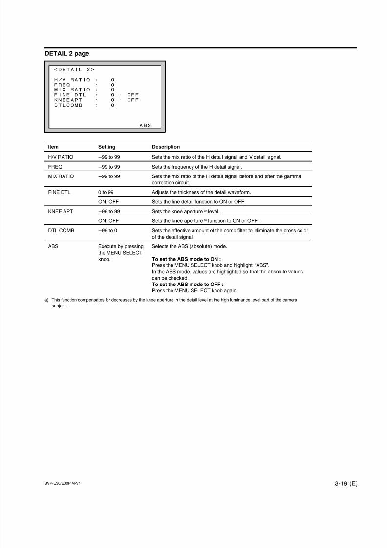
7/14/2019 Bvpe30mmi - Copy
http://slidepdf.com/reader/full/bvpe30mmi-copy 71/136
BVP-E30/E30P M-V1 3-19 (E)
<DETAIL 2>
H/V RATIO : 0
FREQ : 0
MIX RATIO : 0
FINE DTL : 0 : OFFKNEEAPT : 0 : OFF
DTLCOMB : 0
ABS
DETAIL 2 page
Item Setting Description
H/V RATIO _99 to 99 Sets the mix ratio of the H detail signal and V detail signal.
FREQ _99 to 99 Sets the frequency of the H detail signal.
MIX RATIO _99 to 99 Sets the mix ratio of the H detail signal before and after the gamma
correction circuit.
FINE DTL 0 to 99 Adjusts the thickness of the detail waveform.
ON, OFF Sets the fine detail function to ON or OFF.
KNEE APT _99 to 99 Sets the knee aperture a) level.
ON, OFF Sets the knee aperture a) function to ON or OFF.
DTL COMB _99 to 0 Sets the effective amount of the comb filter to eliminate the cross color
of the detail signal.
ABS Execute by pressing Selects the ABS (absolute) mode.
the MENU SELECT
knob. To set the ABS mode to ON :
Press the MENU SELECT knob and highlight “ABS”.
In the ABS mode, values are highlighted so that the absolute values
can be checked.
To set the ABS mode to OFF :
Press the MENU SELECT knob again.
a) This function compensates for decreases by the knee aperture in the detail level at the high luminance level part of the camera
subject.
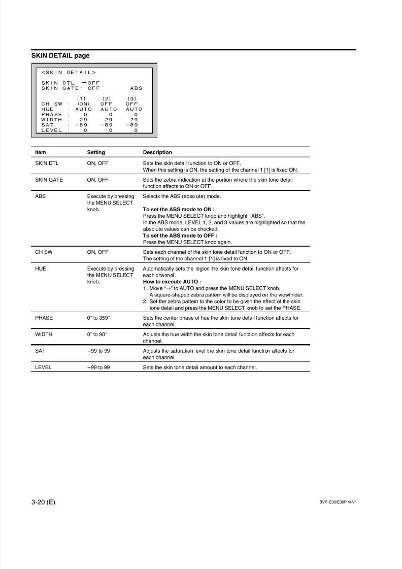
7/14/2019 Bvpe30mmi - Copy
http://slidepdf.com/reader/full/bvpe30mmi-copy 72/136
3-20 (E) BVP-E30/E30P M-V1
<SKIN DETAIL>
SKIN DTL : OFF
SKIN GATE: OFF ABS
[1] [2] [3]CH SW : (ON) OFF OFF
HUE : AUTO AUTO AUTO
PHASE : 0 0 0
WIDTH : 29 29 29
SAT : -89 -89 -89
LEVEL : 0 0 0
SKIN DETAIL page
Item Setting Description
SKIN DTL ON, OFF Sets the skin detail function to ON or OFF.
When this setting is ON, the setting of the channel 1 [1] is fixed ON.
SKIN GATE ON, OFF Sets the zebra indication at the portion where the skin tone detail
function affects to ON or OFF.
ABS Execute by pressing Selects the ABS (absolute) mode.
the MENU SELECT
knob. To set the ABS mode to ON :
Press the MENU SELECT knob and highlight “ABS”.
In the ABS mode, LEVEL 1, 2, and 3 values are highlighted so that the
absolute values can be checked.
To set the ABS mode to OFF :
Press the MENU SELECT knob again.
CH SW ON, OFF Sets each channel of the skin tone detail function to ON or OFF.
The setting of the channel 1 [1] is fixed to ON.
HUE Execute by pressing Automatically sets the region the skin tone detail function affects for
the MENU SELECT each channel.
knob. How to execute AUTO :
1. Move “→” to AUTO and press the MENU SELECT knob.
A square-shaped zebra pattern will be displayed on the viewfinder.
2. Set the zebra pattern to the color to be given the effect of the skin
tone detail and press the MENU SELECT knob to set the PHASE.
PHASE 0d to 359d Sets the center phase of hue the skin tone detail function affects for
each channel.
WIDTH 0d to 90d Adjusts the hue width the skin tone detail function affects for each
channel.
SAT _99 to 99 Adjusts the saturation level the skin tone detail function affects for
each channel.
LEVEL _99 to 99 Sets the skin tone detail amount to each channel.
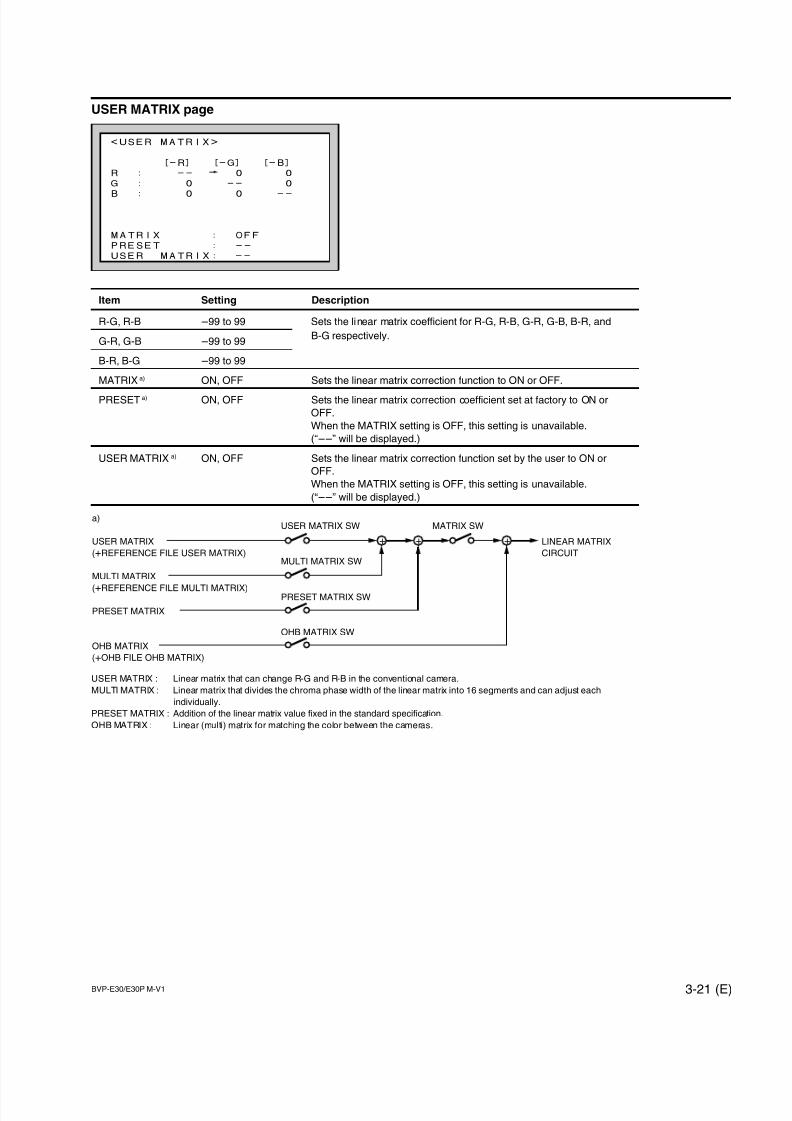
7/14/2019 Bvpe30mmi - Copy
http://slidepdf.com/reader/full/bvpe30mmi-copy 73/136
BVP-E30/E30P M-V1 3-21 (E)
<USER MATRIX>
[-R] [-G] [-B]
R : -- 0 0
G : 0 -- 0
B : 0 0 --
MATRIX : OFF
PRESET : --
USER MATRIX: --
USER MATRIX page
Item Setting Description
R-G, R-B _99 to 99 Sets the linear matrix coefficient for R-G, R-B, G-R, G-B, B-R, and
G-R, G-B _99 to 99B-G respectively.
B-R, B-G _99 to 99
MATRIX a) ON, OFF Sets the linear matrix correction function to ON or OFF.
PRESET a) ON, OFF Sets the linear matrix correction coefficient set at factory to ON or
OFF.
When the MATRIX setting is OFF, this setting is unavailable.
(“__” will be displayed.)
USER MATRIX a) ON, OFF Sets the linear matrix correction function set by the user to ON or
OFF.
When the MATRIX setting is OFF, this setting is unavailable.
(“__” will be displayed.)
USER MATRIX : Linear matrix that can change R-G and R-B in the conventional camera.
MULTI MATRIX : Linear matrix that divides the chroma phase width of the linear matrix into 16 segments and can adjust each
individually.
PRESET MATRIX : Addition of the linear matrix value fixed in the standard specification.
OHB MATRIX : Linear (multi) matrix for matching the color between the cameras.
a)
USER MATRIX
(+REFERENCE FILE USER MATRIX)
MULTI MATRIX
(+REFERENCE FILE MULTI MATRIX)
PRESET MATRIX
OHB MATRIX
(+OHB FILE OHB MATRIX)
+ ++ LINEAR MATRIX
CIRCUITMULTI MATRIX SW
USER MATRIX SW MATRIX SW
PRESET MATRIX SW
OHB MATRIX SW
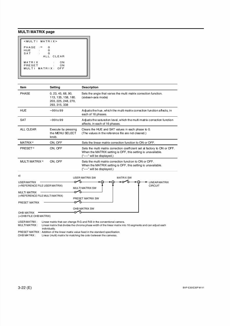
7/14/2019 Bvpe30mmi - Copy
http://slidepdf.com/reader/full/bvpe30mmi-copy 74/136
3-22 (E) BVP-E30/E30P M-V1
<MULTI MATRIX>
PHASE : 0
HUE : 0
SAT : 0
ALL CLEAR
MATRIX : ON
PRESET : ON
MULTI MATRIX: OFF
MULTI MATRIX page
Item Setting Description
PHASE 0, 23, 45, 68, 90, Sets the angle that varies the multi matrix correction function.
113, 135, 158, 180, (sixteen-axis mode)
203, 225, 248, 270,
293, 315, 338
HUE _99 to 99 Adjusts the hue, which the multi matrix correction funct ion affects, in
each of 16 phases.
SAT _99 to 99 Adjusts the saturation level, which the mult i matrix correction funct ion
affects, in each of 16 phases.
ALL CLEAR Execute by pressing Clears the HUE and SAT values in each phase to 0.
the MENU SELECT (The values in the reference file are not cleared.)
knob.
MATRIX a) ON, OFF Sets the linear matrix correction function to ON or OFF.
PRESET a) ON, OFF Sets the multi matrix correction coefficient set at factory to ON or OFF.
When the MATRIX setting is OFF, this setting is unavailable.
(“__” will be displayed.)
MULTI MATRIX a) ON, OFF Sets the multi matrix correction function to ON or OFF.
When the MATRIX setting is OFF, this setting is unavailable.
(“__” will be displayed.)
USER MATRIX : Linear matrix that can change R-G and R-B in the conventional camera.
MULTI MATRIX : Linear matrix that divides the chroma phase width of the linear matrix into 16 segments and can adjust each
individually.PRESET MATRIX : Addition of the linear matrix value fixed in the standard specification.
OHB MATRIX : Linear (multi) matrix for matching the color between the cameras.
a)
USER MATRIX
(+REFERENCE FILE USER MATRIX)
MULTI MATRIX
(+REFERENCE FILE MULTI MATRIX)
PRESET MATRIX
OHB MATRIX
(+OHB FILE OHB MATRIX)
+ ++ LINEAR MATRIX
CIRCUITMULTI MATRIX SW
USER MATRIX SW MATRIX SW
PRESET MATRIX SW
OHB MATRIX SW
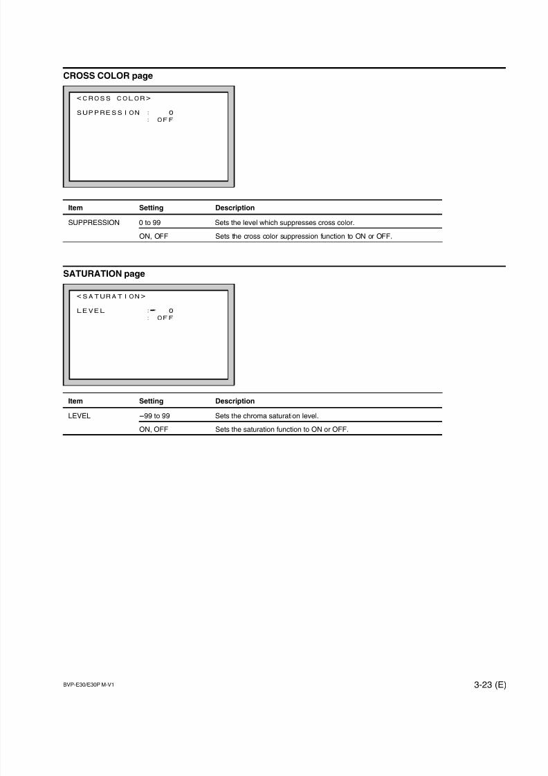
7/14/2019 Bvpe30mmi - Copy
http://slidepdf.com/reader/full/bvpe30mmi-copy 75/136
BVP-E30/E30P M-V1 3-23 (E)
<SATURATION>
LEVEL : 0
: OFF
<CROSS COLOR>
SUPPRESSION : 0
: OFF
CROSS COLOR page
Item Setting Description
SUPPRESSION 0 to 99 Sets the level which suppresses cross color.
ON, OFF Sets the cross color suppression function to ON or OFF.
SATURATION page
Item Setting Description
LEVEL _99 to 99 Sets the chroma saturation level.
ON, OFF Sets the saturation function to ON or OFF.
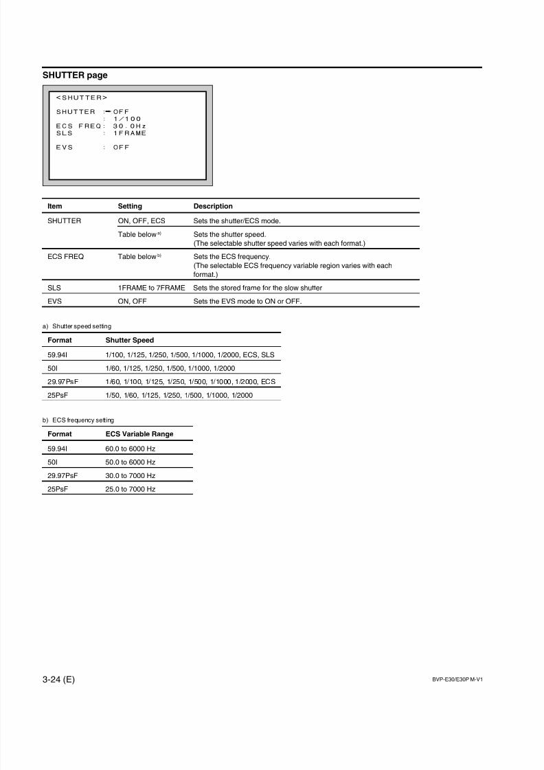
7/14/2019 Bvpe30mmi - Copy
http://slidepdf.com/reader/full/bvpe30mmi-copy 76/136
3-24 (E) BVP-E30/E30P M-V1
<SHUTTER>
SHUTTER : OFF
: 1/100
ECS FREQ: 30.0Hz
SLS : 1FRAME
EVS : OFF
SHUTTER page
Item Setting Description
SHUTTER ON, OFF, ECS Sets the shutter/ECS mode.
Table below a) Sets the shutter speed.
(The selectable shutter speed varies with each format.)
ECS FREQ Table below b) Sets the ECS frequency.
(The selectable ECS frequency variable region varies with each
format.)
SLS 1FRAME to 7FRAME Sets the stored frame for the slow shutter
EVS ON, OFF Sets the EVS mode to ON or OFF.
a) Shutter speed setting
Format Shutter Speed
59.94I 1/100, 1/125, 1/250, 1/500, 1/1000, 1/2000, ECS, SLS
50I 1/60, 1/125, 1/250, 1/500, 1/1000, 1/2000
29.97PsF 1/60, 1/100, 1/125, 1/250, 1/500, 1/1000, 1/2000, ECS
25PsF 1/50, 1/60, 1/125, 1/250, 1/500, 1/1000, 1/2000
b) ECS frequency setting
Format ECS Variable Range
59.94I 60.0 to 6000 Hz
50I 50.0 to 6000 Hz
29.97PsF 30.0 to 7000 Hz
25PsF 25.0 to 7000 Hz
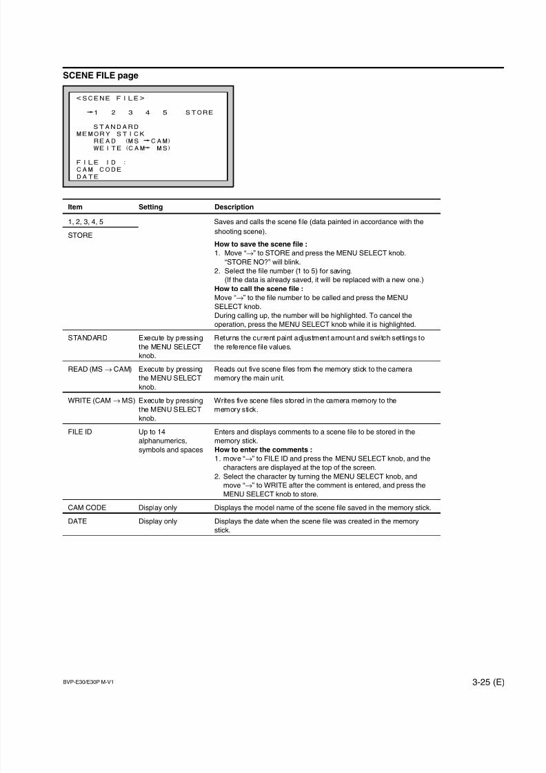
7/14/2019 Bvpe30mmi - Copy
http://slidepdf.com/reader/full/bvpe30mmi-copy 77/136
BVP-E30/E30P M-V1 3-25 (E)
<SCENE FILE>
1 2 3 4 5 STORE
STANDARD
MEMORY STICKREAD (MS CAM)
WEITE(CAM MS)
FILE ID :
CAM CODE
DATE
SCENE FILE page
Item Setting Description
1, 2, 3, 4, 5 Saves and calls the scene file (data painted in accordance with the
STOREshooting scene).
How to save the scene file :
1. Move “→” to STORE and press the MENU SELECT knob.
“STORE NO?” will blink.
2. Select the file number (1 to 5) for saving.(If the data is already saved, it will be replaced with a new one.)
How to call the scene file :
Move “→” to the file number to be called and press the MENU
SELECT knob.
During calling up, the number will be highlighted. To cancel the
operation, press the MENU SELECT knob while it is highlighted.
STANDARD Execute by pressing Returns the current paint adjustment amount and switch settings to
the MENU SELECT the reference file values.
knob.
READ (MS → CAM) Execute by pressing Reads out five scene files from the memory stick to the camera
the MENU SELECT memory the main unit.
knob.
WRITE (CAM → MS) Execute by pressing Writes five scene files stored in the camera memory to the
the MENU SELECT memory stick.
knob.
FILE ID Up to 14 Enters and displays comments to a scene file to be stored in the
alphanumerics, memory stick.
symbols and spaces How to enter the comments :
1. move “→” to FILE ID and press the MENU SELECT knob, and the
characters are displayed at the top of the screen.
2. Select the character by turning the MENU SELECT knob, and
move “→” to WRITE after the comment is entered, and press the
MENU SELECT knob to store.
CAM CODE Display only Displays the model name of the scene file saved in the memory stick.
DATE Display only Displays the date when the scene file was created in the memory
stick.

7/14/2019 Bvpe30mmi - Copy
http://slidepdf.com/reader/full/bvpe30mmi-copy 78/136
3-26 (E) BVP-E30/E30P M-V1
<AUTO SETUP>
AUTO BLACK
AUTO WHITE
AUTO LEVEL
AUTO WHITE SHADING
AUTO BLACK SHADING
TEST SIGNAL: OFF
3-5. MAINTENANCE Menu
This menu consists of paint items used less frequently such as shading adjustment and items required for
camera maintenance.
AUTO SETUP page
Item Setting DescriptionAUTO BLACK Execute by pressing Starts to adjust the black balance automatically.
the MENU SELECT (Pressing the MENU SELECT knob during adjustment cancels the
knob. execution.)
AUTO WHITE Execute by pressing Starts to adjust the white balance automatically.
the MENU SELECT (Pressing the MENU SELECT knob during adjustment cancels the
knob. execution.)
AUTO LEVEL Execute by pressing Starts to adjust the level automatically of the internal camera circuit.
the MENU SELECT (Pressing the MENU SELECT knob during adjustment cancels the
knob. execution.)
AUTO WHITE Execute by pressing Starts to adjust the white shading automatically.
SHADING the MENU SELECT (Pressing the MENU SELECT knob during adjustment cancels the
knob. execution.)
AUTO BLACK Execute by pressing Starts to adjust the black shading automatically.SHADING the MENU SELECT (Pressing the MENU SELECT knob during adjustment cancels the
knob. execution.)
TEST SIGNAL OFF, 1, 2 Selects the test signal.
OFF : No test signal is output.
1 : Outputs the TEST SAW signal.
2 : Outputs the 3STEP or 10STEP TEST signal. a)
a) This is set in TEST 2 MODE of <OTHERS page> on the MAINTENANCE menu.

7/14/2019 Bvpe30mmi - Copy
http://slidepdf.com/reader/full/bvpe30mmi-copy 79/136
BVP-E30/E30P M-V1 3-27 (E)
GENLOCK page
Available only during stand alone.
Item Setting Description
H PHASE [COARSE] _99 to 99 Adjusts the H phase of GENLOCK (coarse).
[FINE] _99 to 99 Adjusts the H phase of GENLOCK (fine).
SC PHASE _99 to 99 Adjusts the SC phase of GENLOCK.
GENLOCK ENABLE, DISABLE Selects whether or not to synchronize the internal reference signal
with the video signal input at the GENLOCK terminal.
VF VIDEO NORMAL, GENLOCK Selects the signal displayed on the viewfinder with the RET switch
pressed when the camera is used alone.
NORMAL : Displays the playback signal.
GENLOCK : Displays the GENLOCK signal.
FORMAT page
Item Setting Description
FORMAT 59.94I, 29.97 PsF Selects interlace system/progressive system (PsF).
(BVP-E30/E30WS only)
50I, 25 PsF
(BVP-E30P/E30WSP
only)
PsF-SHUTTER ON, OFF Turns ON or OFF the function to turn on the shutter automatically
LINK when the progressive system (PsF) is selected.
CROP OFF (16 : 9), Selects the camera aspect ratio.
(BVP-E30WS/ ON (4 : 3)
E30WSP only)
<GENLOCK>
GENLOCKH PHASE[COARSE]: 0
[FINE] : 0
SC PHASE : 0
GENLOCK : ENABLE
VF VIDEO : NORMAL
<FORMAT>
FORMAT : 59.94I
PsF-SHUTTER LINK: OFF
CROP : OFF(16:9)
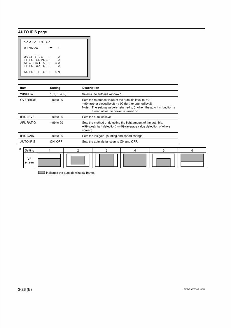
7/14/2019 Bvpe30mmi - Copy
http://slidepdf.com/reader/full/bvpe30mmi-copy 80/136
3-28 (E) BVP-E30/E30P M-V1
AUTO IRIS page
Item Setting Description
WINDOW 1, 2, 3, 4, 5, 6 Selects the auto iris window a).
OVERRIDE _99 to 99 Sets the reference value of the auto iris level to ±2.
_99 (further closed by 2) ↔ 99 (further opened by 2)
Note : The setting value is returned to 0, when the auto iris function is
turned off or the power is turned off.
IRIS LEVEL _99 to 99 Sets the auto iris level.
APL RATIO _99 to 99 Sets the method of detecting the light amount of the auto iris.
_99 (peak light detection) ↔ 99 (average value detection of whole
screen)
IRIS GAIN _99 to 99 Sets the iris gain. (hunting and speed change)
AUTO IRIS ON, OFF Sets the auto iris function to ON and OFF.
<AUTO IRIS>
WINDOW : 1
OVERRIDE : 0IRIS LEVEL: 0
APL RATIO : 80
IRIS GAIN : 0
AUTO IRIS : ON
5 64321a)
Setting
VFscreen
indicates the auto iris window frame.
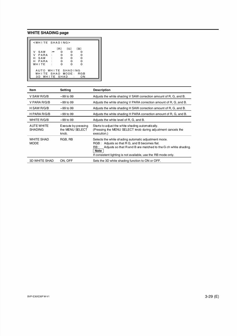
7/14/2019 Bvpe30mmi - Copy
http://slidepdf.com/reader/full/bvpe30mmi-copy 81/136
BVP-E30/E30P M-V1 3-29 (E)
WHITE SHADING page
Item Setting Description
V SAW R/G/B _99 to 99 Adjusts the white shading V SAW correction amount of R, G, and B.
V PARA R/G/B _99 to 99 Adjusts the white shading V PARA correction amount of R, G, and B.
H SAW R/G/B _99 to 99 Adjusts the white shading H SAW correction amount of R, G, and B.
H PARA R/G/B _99 to 99 Adjusts the white shading H PARA correction amount of R, G, and B.
WHITE R/G/B _99 to 99 Adjusts the white level of R, G, and B.
AUTE WHITE Execute by pressing Starts to adjust the white shading automatically.
SHADING the MENU SELECT (Pressing the MENU SELECT knob during adjustment cancels the
knob. execution.)
WHITE SHAD RGB, RB Selects the white shading automatic adjustment mode.
MODE RGB : Adjusts so that R G, and B becomes flat.
RB : Adjusts so that R and B are matched to the G ch white shading.
nIf consistent lighting is not available, use the RB mode only.
3D WHITE SHAD ON, OFF Sets the 3D white shading function to ON or OFF.
<WHITE SHADING>
[R] [G] [B]
V SAW : 0 0 0
V PARA : 0 0 0
H SAW : 0 0 0H PARA : 0 0 0
WHITE : 0 0 0
AUTO WHITE SHADING
WHITE SHAD MODE: RGB
3D WHITE SHAD : ON
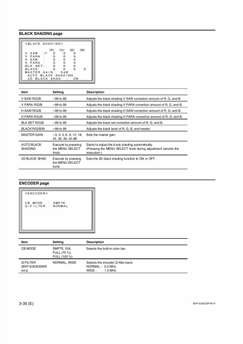
7/14/2019 Bvpe30mmi - Copy
http://slidepdf.com/reader/full/bvpe30mmi-copy 82/136
3-30 (E) BVP-E30/E30P M-V1
BLACK SHADING page
Item Setting Description
V SAW R/G/B _99 to 99 Adjusts the black shading V SAW correction amount of R, G, and B.
V PARA R/G/B _99 to 99 Adjusts the black shading V PARA correction amount of R, G, and B.
H SAW R/G/B _99 to 99 Adjusts the black shading H SAW correction amount of R, G, and B.
H PARA R/G/B _99 to 99 Adjusts the black shading H PARA correction amount of R, G, and B.
BLK SET R/G/B _99 to 99 Adjusts the black set correction amount of R, G, and B.
BLACK R/G/B/M _99 to 99 Adjusts the black level of R, G, B, and master.
MASTER GAIN _3, 0, 3, 6, 9, 12, 18, Sets the master gain.
24, 30, 36, 42 dB
AUTO BLACK Execute by pressing Starts to adjust the black shading automatically.
SHADING the MENU SELECT (Pressing the MENU SELECT knob during adjustment cancels the
knob. execution.)
2D BLACK SHAD Execute by pressing Sets the 2D black shading function to ON or OFF.
the MENU SELECT
konb.
ENCODER page
Item Setting Description
CB MODE SMPTE, EIA, Selects the built-in color bar.
FULL (75 %),
FULL (100 %)
Q-FILTER NORMAL, WIDE Selects the encoder Q filter band
(BVP-E30/E30WS NORMAL : 0.5 MHz
only) WIDE : 1.3 MHz
<BLACK SHADING>
[R] [G] [B] [M]
V SAW : 0 0 0
V PARA : 0 0 0
H SAW : 0 0 0H PARA : 0 0 0
BLK SET: 0 0 0
BLACK : 0 0 0 0
MASTER GAIN: 0dB
AUTO BLACK SHADING
2D BLACK SHAD : ON
<ENCODER>
CB MODE : SMPTE
Q-FILTER : NORMAL
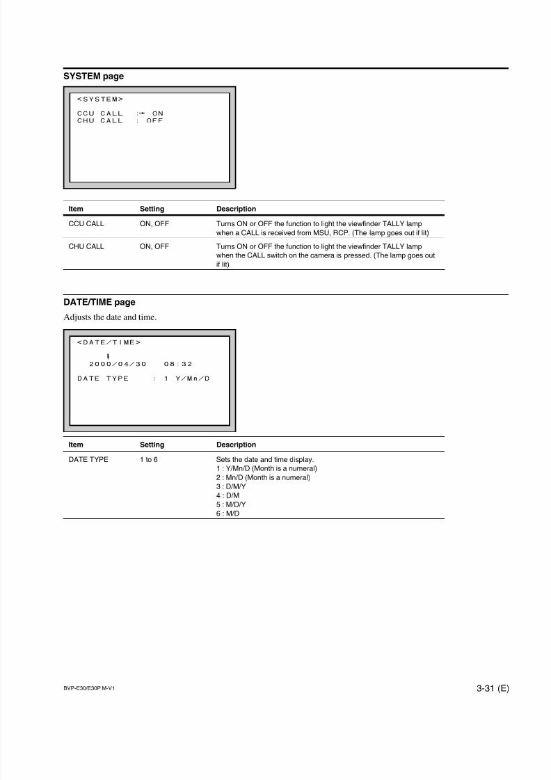
7/14/2019 Bvpe30mmi - Copy
http://slidepdf.com/reader/full/bvpe30mmi-copy 83/136
BVP-E30/E30P M-V1 3-31 (E)
SYSTEM page
Item Setting Description
CCU CALL ON, OFF Turns ON or OFF the function to light the viewfinder TALLY lamp
when a CALL is received from MSU, RCP. (The lamp goes out if lit)
CHU CALL ON, OFF Turns ON or OFF the function to light the viewfinder TALLY lamp
when the CALL switch on the camera is pressed. (The lamp goes out
if lit)
DATE/TIME page
Adjusts the date and time.
Item Setting Description
DATE TYPE 1 to 6 Sets the date and time display.
1 : Y/Mn/D (Month is a numeral)
2 : Mn/D (Month is a numeral)
3 : D/M/Y
4 : D/M
5 : M/D/Y
6 : M/D
<SYSTEM>
CCU CALL : ON
CHU CALL : OFF
<DATE/TIME>
2000/04/30 08:32
DATE TYPE : 1 Y/Mn/D
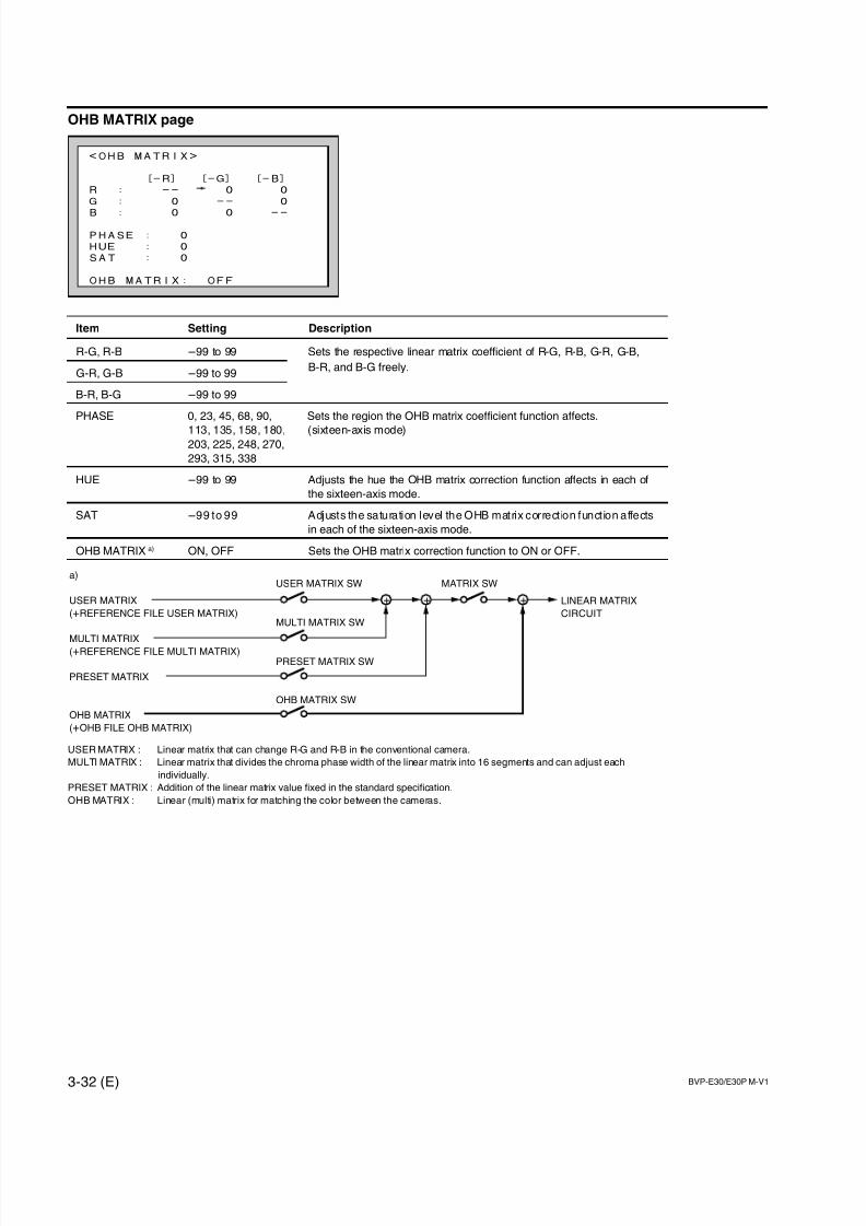
7/14/2019 Bvpe30mmi - Copy
http://slidepdf.com/reader/full/bvpe30mmi-copy 84/136
3-32 (E) BVP-E30/E30P M-V1
OHB MATRIX page
Item Setting Description
R-G, R-B _99 to 99 Sets the respective linear matrix coefficient of R-G, R-B, G-R, G-B,
G-R, G-B _99 to 99B-R, and B-G freely.
B-R, B-G _99 to 99
PHASE 0, 23, 45, 68, 90, Sets the region the OHB matrix coefficient function affects.
113, 135, 158, 180, (sixteen-axis mode)203, 225, 248, 270,
293, 315, 338
HUE _99 to 99 Adjusts the hue the OHB matrix correction function affects in each of
the sixteen-axis mode.
SAT _99 to 99 Adjusts the saturation level the OHB matrix correct ion funct ion affects
in each of the sixteen-axis mode.
OHB MATRIX a) ON, OFF Sets the OHB matrix correction function to ON or OFF.
USER MATRIX : Linear matrix that can change R-G and R-B in the conventional camera.
MULTI MATRIX : Linear matrix that divides the chroma phase width of the linear matrix into 16 segments and can adjust each
individually.
PRESET MATRIX : Addition of the linear matrix value fixed in the standard specification.
OHB MATRIX : Linear (multi) matrix for matching the color between the cameras.
<OHB MATRIX>
[-R] [-G] [-B]
R : -- 0 0
G : 0 -- 0
B : 0 0 --
PHASE : 0
HUE : 0
SAT : 0
OHB MATRIX: OFF
a)
USER MATRIX
(+REFERENCE FILE USER MATRIX)
MULTI MATRIX
(+REFERENCE FILE MULTI MATRIX)
PRESET MATRIX
OHB MATRIX
(+OHB FILE OHB MATRIX)
+ ++ LINEAR MATRIX
CIRCUITMULTI MATRIX SW
USER MATRIX SW MATRIX SW
PRESET MATRIX SW
OHB MATRIX SW
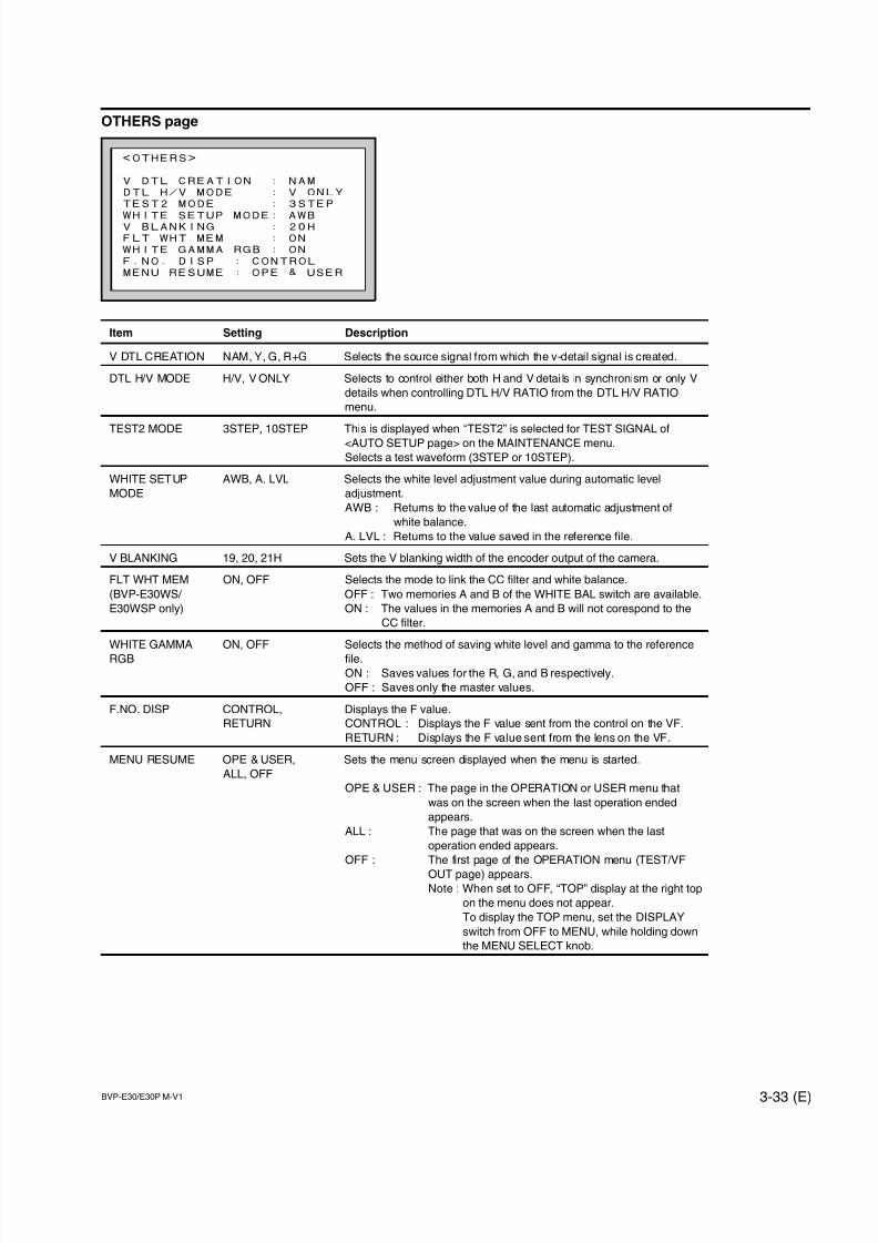
7/14/2019 Bvpe30mmi - Copy
http://slidepdf.com/reader/full/bvpe30mmi-copy 85/136
BVP-E30/E30P M-V1 3-33 (E)
OTHERS page
Item Setting Description
V DTL CREATION NAM, Y, G, R+G Selects the source signal from which the v-detail signal is created.
DTL H/V MODE H/V, V ONLY Selects to control either both H and V detai ls in synchronism or only V
details when controlling DTL H/V RATIO from the DTL H/V RATIO
menu.
TEST2 MODE 3STEP, 10STEP This is displayed when “TEST2” is selected for TEST SIGNAL of
<AUTO SETUP page> on the MAINTENANCE menu.
Selects a test waveform (3STEP or 10STEP).
WHITE SETUP AWB, A. LVL Selects the white level adjustment value during automatic level
MODE adjustment.
AWB : Returns to the value of the last automatic adjustment of
white balance.
A. LVL : Returns to the value saved in the reference file.
V BLANKING 19, 20, 21H Sets the V blanking width of the encoder output of the camera.
FLT WHT MEM ON, OFF Selects the mode to link the CC filter and white balance.
(BVP-E30WS/ OFF : Two memories A and B of the WHITE BAL switch are available.
E30WSP only) ON : The values in the memories A and B will not corespond to the
CC filter.
WHITE GAMMA ON, OFF Selects the method of saving white level and gamma to the reference
RGB file.
ON : Saves values for the R, G, and B respectively.
OFF : Saves only the master values.
F.NO. DISP CONTROL, Displays the F value.
RETURN CONTROL : Displays the F value sent from the control on the VF.
RETURN : Displays the F value sent from the lens on the VF.
MENU RESUME OPE & USER, Sets the menu screen displayed when the menu is started.
ALL, OFF
OPE & USER : The page in the OPERATION or USER menu that
was on the screen when the last operation ended
appears.
ALL : The page that was on the screen when the last
operation ended appears.
OFF : The first page of the OPERATION menu (TEST/VF
OUT page) appears.Note : When set to OFF, “TOP” display at the right top
on the menu does not appear.
To display the TOP menu, set the DISPLAY
switch from OFF to MENU, while holding down
the MENU SELECT knob.
<OTHERS>
V DTL CREATION : NAM
DTL H/V MODE : V ONLY
TEST2 MODE : 3STEP
WHITE SETUP MODE: AWBV BLANKING : 20H
FLT WHT MEM : ON
WHITE GAMMA RGB : ON
F.NO. DISP : CONTROL
MENU RESUME : OPE & USER
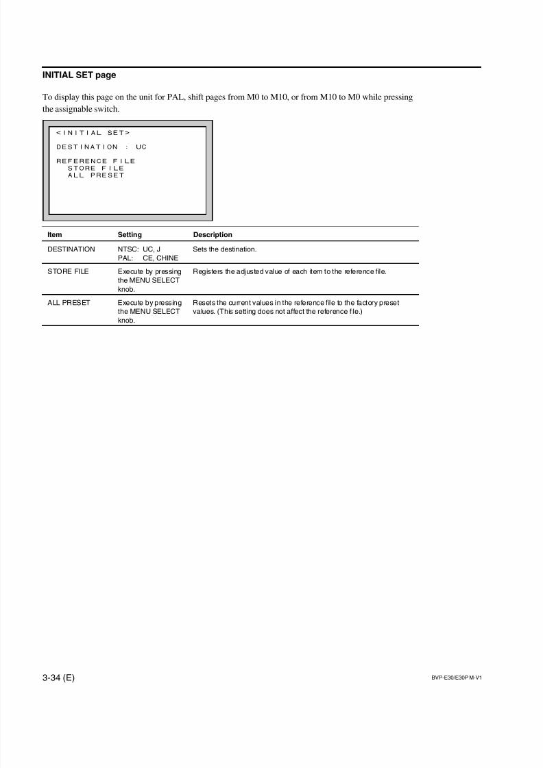
7/14/2019 Bvpe30mmi - Copy
http://slidepdf.com/reader/full/bvpe30mmi-copy 86/136
3-34 (E) BVP-E30/E30P M-V1
<INITIAL SET>
DESTINATION : UC
REFERENCE FILE
STORE FILE
ALL PRESET
INITIAL SET page
To display this page on the unit for PAL, shift pages from M0 to M10, or from M10 to M0 while pressing
the assignable switch.
Item Setting Description
DESTINATION NTSC: UC, J Sets the destination.
PAL: CE, CHINE
STORE FILE Execute by pressing Registers the adjusted value of each item to the reference file.the MENU SELECT
knob.
ALL PRESET Execute by pressing Resets the current values in the reference file to the factory preset
the MENU SELECT values. (This setting does not affect the reference file.)
knob.
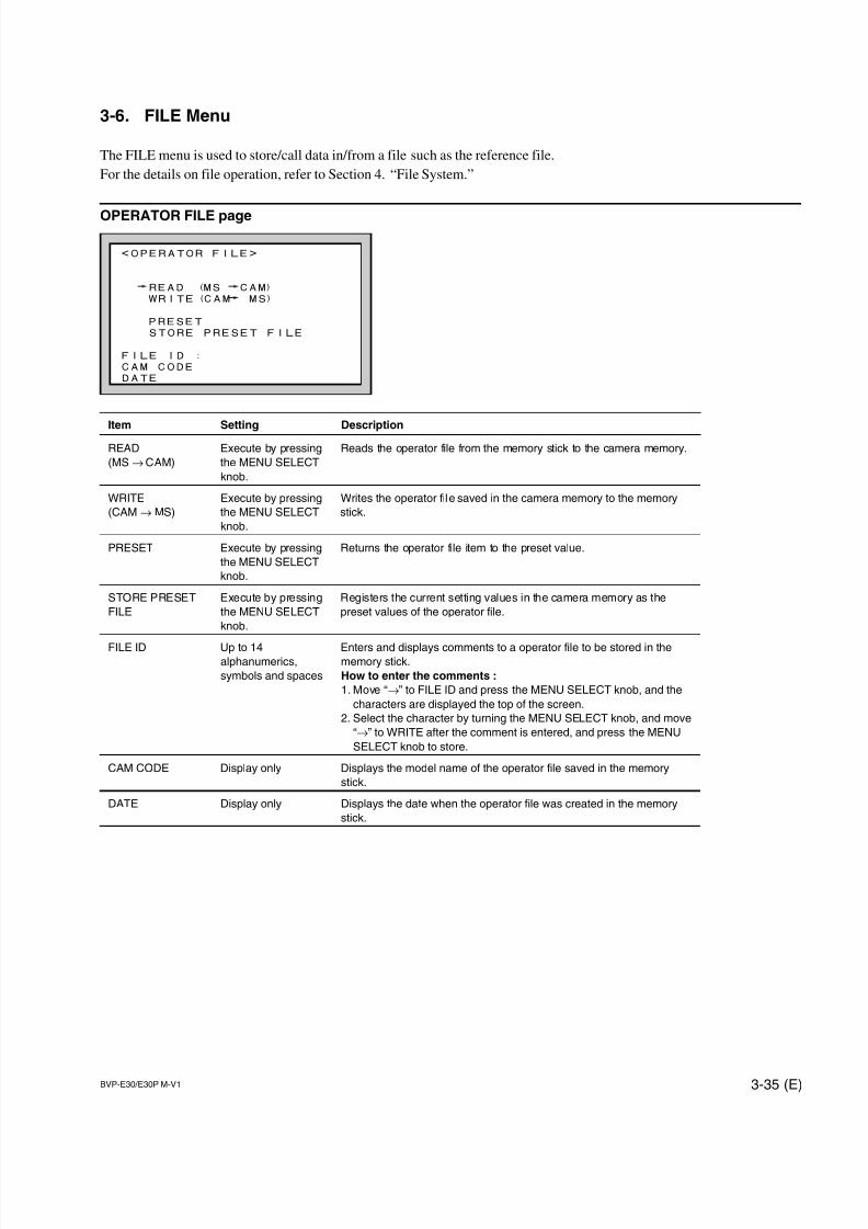
7/14/2019 Bvpe30mmi - Copy
http://slidepdf.com/reader/full/bvpe30mmi-copy 87/136
BVP-E30/E30P M-V1 3-35 (E)
3-6. FILE Menu
The FILE menu is used to store/call data in/from a file such as the reference file.
For the details on file operation, refer to Section 4. “File System.”
OPERATOR FILE page
Item Setting DescriptionREAD Execute by pressing Reads the operator file from the memory stick to the camera memory.
(MS→ CAM) the MENU SELECT
knob.
WRITE Execute by pressing Writes the operator file saved in the camera memory to the memory
(CAM→ MS) the MENU SELECT stick.
knob.
PRESET Execute by pressing Returns the operator file item to the preset value.
the MENU SELECT
knob.
STORE PRESET Execute by pressing Registers the current setting values in the camera memory as the
FILE the MENU SELECT preset values of the operator file.
knob.
FILE ID Up to 14 Enters and displays comments to a operator file to be stored in thealphanumerics, memory stick.
symbols and spaces How to enter the comments :
1. Move “→” to FILE ID and press the MENU SELECT knob, and the
characters are displayed the top of the screen.
2. Select the character by turning the MENU SELECT knob, and move
“→” to WRITE after the comment is entered, and press the MENU
SELECT knob to store.
CAM CODE Display only Displays the model name of the operator file saved in the memory
stick.
DATE Display only Displays the date when the operator file was created in the memory
stick.
<OPERATOR FILE>
READ (MS CAM)
WRITE(CAM MS)
PRESET
STORE PRESET FILE
FILE ID :
CAM CODE
DATE
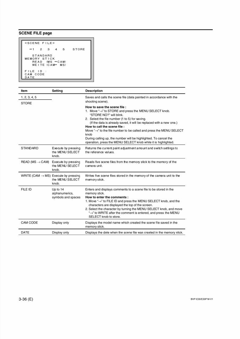
7/14/2019 Bvpe30mmi - Copy
http://slidepdf.com/reader/full/bvpe30mmi-copy 88/136
3-36 (E) BVP-E30/E30P M-V1
SCENE FILE page
Item Setting Description
1, 2, 3, 4, 5 Saves and calls the scene file (data painted in accordance with the
STOREshooting scene).
How to save the scene file :
1. Move “→” to STORE and press the MENU SELECT knob.
“STORE NO?” will blink.
2. Select the file number (1 to 5) for saving.(If the data is already saved, it will be replaced with a new one.)
How to call the scene file :
Move “→” to the file number to be called and press the MENU SELECT
knob
During calling up, the number will be highlighted. To cancel the
operation, press the MENU SELECT knob while it is highlighted.
STANDARD Execute by pressing Returns the current paint adjustment amount and switch settings to
the MENU SELECT the reference values.
knob.
READ (MS → CAM) Execute by pressing Reads five scene files from the memory stick to the memory of the
the MENU SELECT camera unit .
knob.
WRITE (CAM → MS) Execute by pressing Writes five scene files stored in the memory of the camera unit to the
the MENU SELECT memory stick.
knob.
FILE ID Up to 14 Enters and displays comments to a scene file to be stored in the
alphanumerics, memory stick.
symbols and spaces How to enter the comments :
1. Move “→” to FILE ID and press the MENU SELECT knob, and the
characters are displayed the top of the screen.
2. Select the character by turning the MENU SELECT knob, and move
“→” to WRITE after the comment is entered, and press the MENU
SELECT knob to store.
CAM CODE Display only Displays the model name which created the scene file saved in the
memory stick.
DATE Display only Displays the date when the scene file was created in the memory stick.
<SCENE FILE>
1 2 3 4 5 STORE
STANDARD
MEMORY STICKREAD (MS CAM)
WEITE(CAM MS)
FILE ID :
CAM CODE
DATE
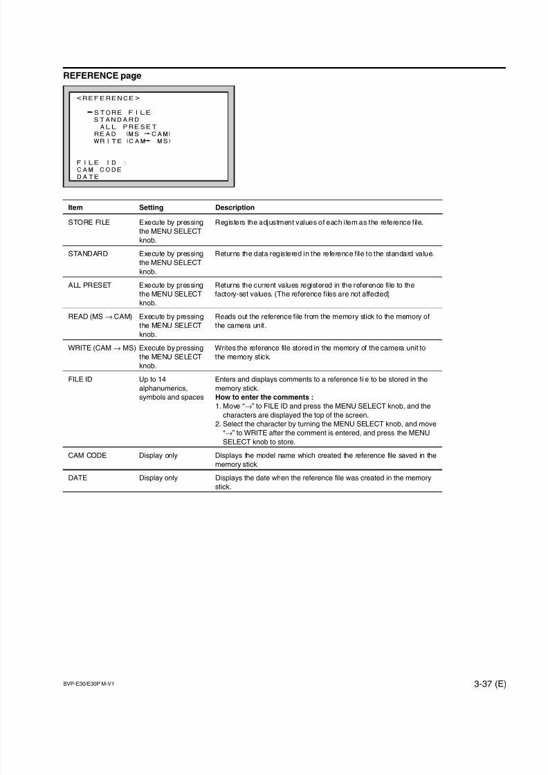
7/14/2019 Bvpe30mmi - Copy
http://slidepdf.com/reader/full/bvpe30mmi-copy 89/136
BVP-E30/E30P M-V1 3-37 (E)
REFERENCE page
Item Setting Description
STORE FILE Execute by pressing Registers the adjustment values of each item as the reference file.
the MENU SELECT
knob.
STANDARD Execute by pressing Returns the data registered in the reference file to the standard value.
the MENU SELECT
knob.
ALL PRESET Execute by pressing Returns the current values registered in the reference file to the
the MENU SELECT factory-set values. (The reference files are not affected)
knob.
READ (MS → CAM) Execute by pressing Reads out the reference file from the memory stick to the memory of
the MENU SELECT the camera unit.
knob.
WRITE (CAM → MS) Execute by pressing Writes the reference file stored in the memory of the camera unit to
the MENU SELECT the memory stick.
knob.
FILE ID Up to 14 Enters and displays comments to a reference file to be stored in the
alphanumerics, memory stick.
symbols and spaces How to enter the comments :
1. Move “→” to FILE ID and press the MENU SELECT knob, and thecharacters are displayed the top of the screen.
2. Select the character by turning the MENU SELECT knob, and move
“→” to WRITE after the comment is entered, and press the MENU
SELECT knob to store.
CAM CODE Display only Displays the model name which created the reference file saved in the
memory stick.
DATE Display only Displays the date when the reference file was created in the memory
stick.
<REFERENCE>
STORE FILE
STANDARD
ALL PRESET
READ (MS CAM)WRITE(CAM MS)
FILE ID :
CAM CODE
DATE
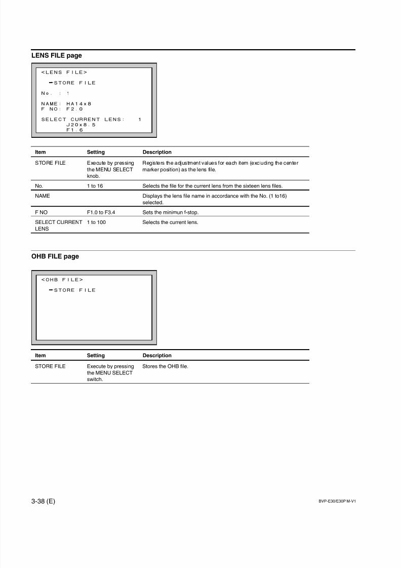
7/14/2019 Bvpe30mmi - Copy
http://slidepdf.com/reader/full/bvpe30mmi-copy 90/136
3-38 (E) BVP-E30/E30P M-V1
<OHB FILE>
STORE FILE
LENS FILE page
Item Setting Description
STORE FILE Execute by pressing Registers the adjustment values for each item (excluding the center
the MENU SELECT marker position) as the lens file.
knob.
No. 1 to 16 Selects the file for the current lens from the sixteen lens files.
NAME Displays the lens file name in accordance with the No. (1 to16)
selected.
F NO F1.0 to F3.4 Sets the minimun f-stop.
SELECT CURRENT 1 to 100 Selects the current lens.
LENS
OHB FILE page
Item Setting Description
STORE FILE Execute by pressing Stores the OHB file.
the MENU SELECT
switch.
<LENS FILE>
STORE FILE
No. : 1
NAME: HA14x8
F NO: F2.0
SELECT CURRENT LENS: 1
J20x8.5
F1.6
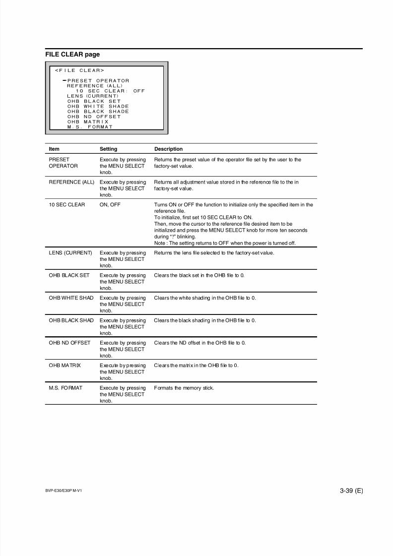
7/14/2019 Bvpe30mmi - Copy
http://slidepdf.com/reader/full/bvpe30mmi-copy 91/136
BVP-E30/E30P M-V1 3-39 (E)
<FILE CLEAR>
PRESET OPERATOR
REFERENCE(ALL)
10 SEC CLEAR: OFF
LENS(CURRENT)OHB BLACK SET
OHB WHITE SHADE
OHB BLACK SHADE
OHB ND OFFSET
OHB MATRIX
M.S. FORMAT
FILE CLEAR page
Item Setting Description
PRESET Execute by pressing Returns the preset value of the operator file set by the user to the
OPERATOR the MENU SELECT factory-set value.
knob.
REFERENCE (ALL) Execute by pressing Returns all adjustment value stored in the reference file to the in
the MENU SELECT factory-set value.
knob.
10 SEC CLEAR ON, OFF Turns ON or OFF the function to initialize only the specified item in the
reference file.
To initialize, first set 10 SEC CLEAR to ON.
Then, move the cursor to the reference file desired item to be
initialized and press the MENU SELECT knob for more ten seconds
during “?” blinking.
Note : The setting returns to OFF when the power is turned off.
LENS (CURRENT) Execute by pressing Returns the lens file selected to the factory-set value.
the MENU SELECT
knob.
OHB BLACK SET Execute by pressing Clears the black set in the OHB file to 0.
the MENU SELECT
knob.
OHB WHITE SHAD Execute by pressing Clears the white shading in the OHB file to 0.
the MENU SELECT
knob.
OHB BLACK SHAD Execute by pressing Clears the black shading in the OHB file to 0.
the MENU SELECT
knob.
OHB ND OFFSET Execute by pressing Clears the ND offset in the OHB file to 0.
the MENU SELECT
knob.
OHB MATRIX Execute by pressing Clears the matrix in the OHB fi le to 0.
the MENU SELECT
knob.
M.S. FORMAT Execute by pressing Formats the memory stick.the MENU SELECT
knob.
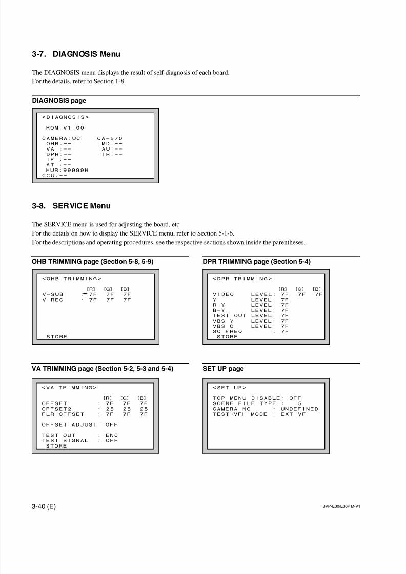
7/14/2019 Bvpe30mmi - Copy
http://slidepdf.com/reader/full/bvpe30mmi-copy 92/136
3-40 (E) BVP-E30/E30P M-V1
<SET UP>
TOP MENU DISABLE: OFF
SCENE FILE TYPE : 5CAMERA NO : UNDEFINED
TEST(VF) MODE : EXT VF
<DPR TRIMMING>
[R] [G] [B]
VIDEO LEVEL: 7F 7F 7F
Y LEVEL: 7F
R-Y LEVEL: 7F
B-Y LEVEL: 7F
TEST OUT LEVEL: 7F
VBS Y LEVEL: 7F
VBS C LEVEL: 7F
SC FREQ : 7F
STORE
<VA TRIMMING>
[R] [G] [B]
OFFSET : 7E 7E 7FOFFSET2 : 25 25 25
FLR OFFSET : 7F 7F 7F
OFFSET ADJUST: OFF
TEST OUT : ENC
TEST SIGNAL : OFF
STORE
3-7. DIAGNOSIS Menu
The DIAGNOSIS menu displays the result of self-diagnosis of each board.
For the details, refer to Section 1-8.
DIAGNOSIS page
3-8. SERVICE Menu
The SERVICE menu is used for adjusting the board, etc.
For the details on how to display the SERVICE menu, refer to Section 5-1-6.
For the descriptions and operating procedures, see the respective sections shown inside the parentheses.
<DIAGNOSIS>
ROM:V1.00
CAMERA:UC CA-570
OHB:-- MD:--
VA :-- AU:--
DPR:-- TR:--
IF :--
AT :--
HUR:99999H
CCU:--
<OHB TRIMMING>
[R] [G] [B]
V-SUB : 7F 7F 7F
V-REG : 7F 7F 7F
STORE
OHB TRIMMING page (Section 5-8, 5-9)
VA TRIMMING page (Section 5-2, 5-3 and 5-4)
DPR TRIMMING page (Section 5-4)
SET UP page
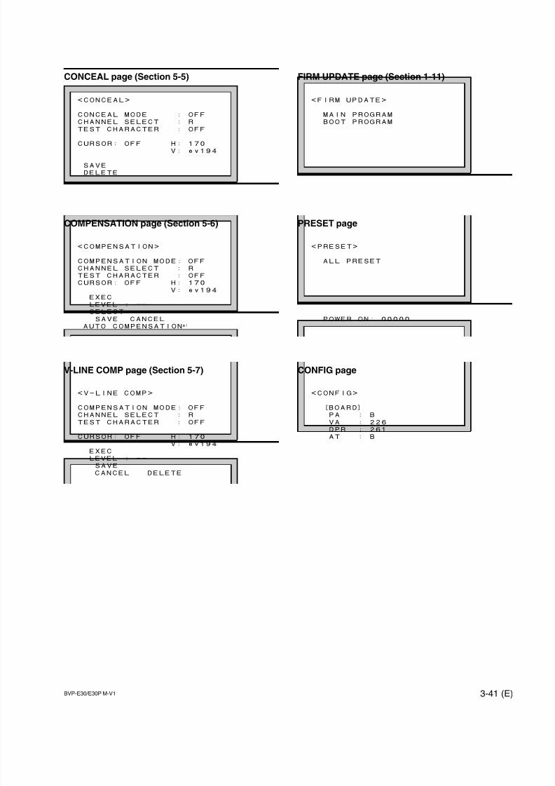
7/14/2019 Bvpe30mmi - Copy
http://slidepdf.com/reader/full/bvpe30mmi-copy 93/136
BVP-E30/E30P M-V1 3-41 (E)
<CONFIG>
[BOARD]
PA : BVA : 226
DPR : 261
AT : B
<PRESET>
ALL PRESET
POWER ON: 00000
CONCEAL page (Section 5-5)
COMPENSATION page (Section 5-6)
V-LINE COMP page (Section 5-7)
<CONCEAL>
CONCEAL MODE : OFF
CHANNEL SELECT : R
TEST CHARACTER : OFF
CURSOR: OFF H: 170
V: ev194
SAVE
DELETE
<FIRM UPDATE>
MAIN PROGRAM
BOOT PROGRAM
FIRM UPDATE page (Section 1-11)
PRESET page
CONFIG page
<COMPENSATION>
COMPENSATION MODE: OFF
CHANNEL SELECT : R
TEST CHARACTER : OFFCURSOR: OFF H: 170
V: ev194
EXEC
LEVEL : --
SELECT: --
SAVE CANCEL
AUTO COMPENSATIONa)
<V-LINE COMP>
COMPENSATION MODE: OFF
CHANNEL SELECT : RTEST CHARACTER : OFF
CURSOR: OFF H: 170
V: ev194
EXEC
LEVEL : --
SAVE
CANCEL DELETE

7/14/2019 Bvpe30mmi - Copy
http://slidepdf.com/reader/full/bvpe30mmi-copy 94/136
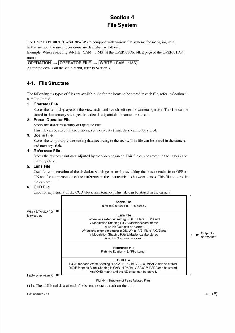
7/14/2019 Bvpe30mmi - Copy
http://slidepdf.com/reader/full/bvpe30mmi-copy 95/136
BVP-E30/E30P M-V1 4-1 (E)
Section 4
File System
The BVP-E30/E30P/E30WS/E30WSP are equipped with various file systems for managing data.
In this section, the menu operations are described as follows.
Example: When executing WRITE (CAM →MS) at the OPERATOR FILE page of the OPERATION
menu.
As for the details on the setup menu, refer to Section 3.
4-1. File Structure
The following six types of files are available. As for the items to be stored in each file, refer to Section 4-
8. “ File Items”.
1. Operator File
Stores the items displayed on the viewfinder and switch settings for camera operator. This file can be
stored in the memory stick, yet the video data (paint data) cannot be stored.
2. Preset Operator File
Stores the standard settings of Operator File.
This file can be stored in the camera, yet video data (paint data) cannot be stored.
3. Scene File
Stores the temporary video setting data according to the scene. This file can be stored in the camera
and memory stick.
4. Reference File
Stores the custom paint data adjusted by the video engineer. This file can be stored in the camera and
memory stick.
5. Lens File
Used for compensation of the deviation which generates by switching the lens extender from OFF to
ON and for compensation of the difference in the characteristics between lenses. This file is stored in
the camera.
6. OHB File
Used for adjustment of the CCD block maintenance. This file can be stored in the camera.
(*1): The additional data of each file is sent to each circuit on the unit.
Scene File
Refer to Section 4-8. “File Items”.
Reference File
Refer to Section 4-8. “File Items”.
Lens File
When lens extender setting is OFF, Flare R/G/B and
V Modulation Shading R/G/B/Master can be stored.
Auto Iris Gain can be stored.
When lens extender setting is ON, White R/B, Flare R/G/B and
V Modulation Shading R/G/B/Master can be stored.Auto Iris Gain can be stored.
OHB File
R/G/B for each White Shading H SAW, H PARA, V SAW, VPARA can be stored.
R/G/B for each Black Shading H SAW, H PARA, V SAW, V PARA can be stored.
And OHB matrix and the ND offset can be stored.
When STANDARD
is executed
Factory-set value 0
Fig. 4-1. Structure of Paint Related Files
Output tohardware (*1)
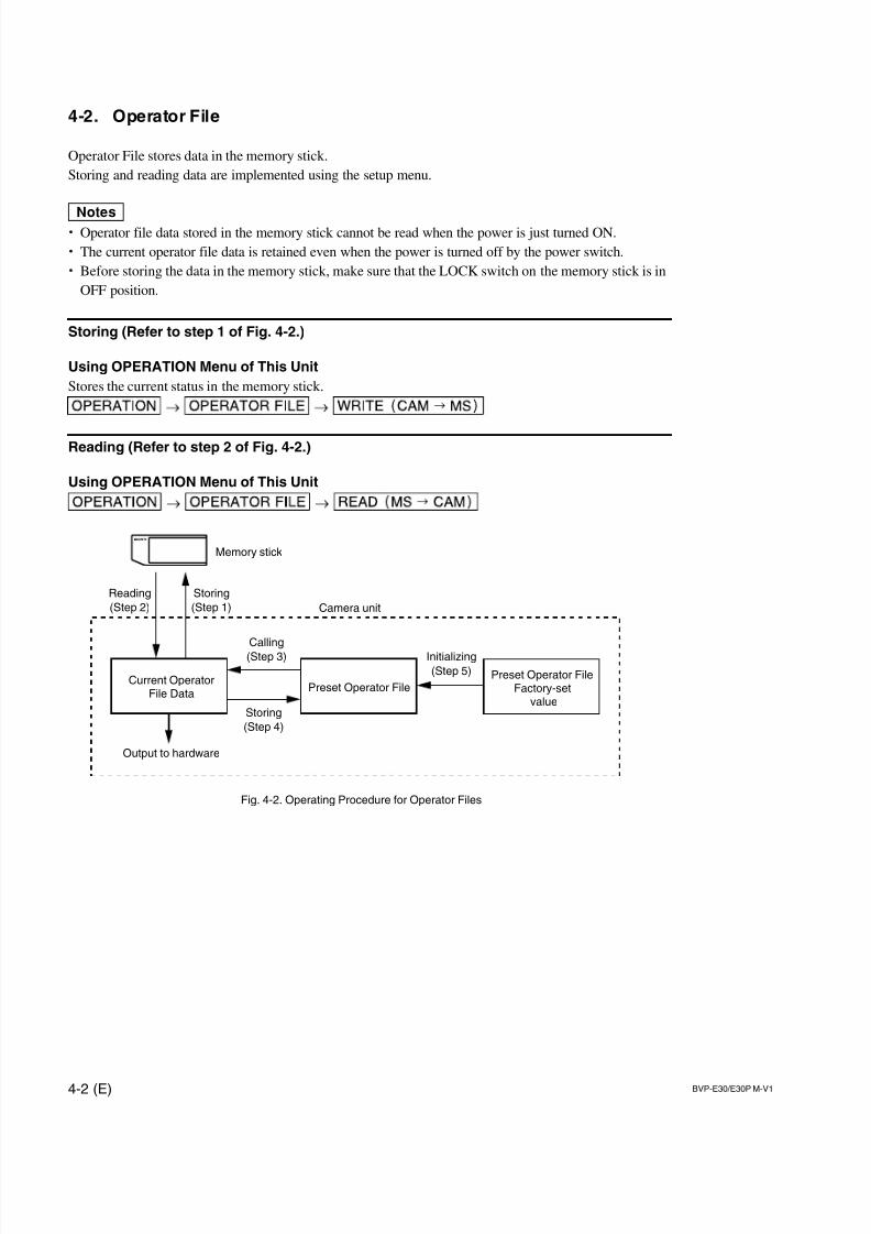
7/14/2019 Bvpe30mmi - Copy
http://slidepdf.com/reader/full/bvpe30mmi-copy 96/136
4-2 (E) BVP-E30/E30P M-V1
Camera unit
Storing
(Step 4)
Storing
(Step 1)
Reading
(Step 2)
Initializing
(Step 5)
Calling
(Step 3)
Current OperatorFile Data
Output to hardware
Memory stick
Preset Operator FilePreset Operator File
Factory-setvalue
Fig. 4-2. Operating Procedure for Operator Files
4-2. Operator File
Operator File stores data in the memory stick.
Storing and reading data are implemented using the setup menu.
m. Operator file data stored in the memory stick cannot be read when the power is just turned ON.
. The current operator file data is retained even when the power is turned off by the power switch.
. Before storing the data in the memory stick, make sure that the LOCK switch on the memory stick is in
OFF position.
Storing (Refer to step 1 of Fig. 4-2.)
Using OPERATION Menu of This Unit
Stores the current status in the memory stick.
Reading (Refer to step 2 of Fig. 4-2.)
Using OPERATION Menu of This Unit

7/14/2019 Bvpe30mmi - Copy
http://slidepdf.com/reader/full/bvpe30mmi-copy 97/136
BVP-E30/E30P M-V1 4-3 (E)
4-3. Preset Operator File
Preset Operator File stores data in the camera.
Calling and Storing data are implemented using the setup menu.
Items to be stored as Preset Operator file are the same as Operator File.
Calling (Refer to step 3 of Fig. 4-2.)
Using OPERATION Menu of This Unit
[OPERATION] → [OPERATOR|FILE] → [PRESET]
Storing (Refer to step 4 of Fig. 4-2.)
Using FILE Menu of This Unit
Use when you want to store the current settings in the Preset Operator File as the standard settings of
Operator File.
[FILE] → [OPERATOR|FILE] → [STORE|PRESET|FILE]
Initializing (Refer to step 5 of Fig. 4-2.)
Using FILE Menu of This Unit
Use when initializing the changed Preset Operator File data to their factory-set values.
[FILE] → [FILE|CLEAR] → [PRESET|OPERATOR]
7/14/2019 Bvpe30mmi - Copy
http://slidepdf.com/reader/full/bvpe30mmi-copy 98/136
4-4 (E) BVP-E30/E30P M-V1
4-4. Scene File
Scene File stores data in the camera and memory stick.
It also stores in the IC memory card if the MSU (master setup unit) is used. For the details, refer to the
MSU operation manual.
Storing and calling data are implemented using the setup menu or MSU.Scene files can be copied between cameras using the memory stick.
m. Scene Files are files for storing the differences from the Reference File. Therefore when the Reference
File is changed, output of the Scene File item corresponding with the item changed in the Reference
File is also changed.
. Before storing the data in the memory stick, make sure that the LOCK switch on the memory stick is in
OFF position.
Storing (Refer to step 1 of Fig.4-3.)
Using PAINT Menu of This Unit
(1) Change the scene file item to the desired value.
(2) [PAINT] → [SCENE|FILE] → [STORE]Select the scene file number to be stored.
With MSU
(1) Change the scene file item to the desired value.
(2) Press “STORE” of the scene file, and press the STORE number.
Calling and Clearing the Call (Refer to step 2 of Fig.4-3.)
Using PAINT Menu of This Unit
Select the scene file number to be called on the “SCENE FILE” page. A file currently being called is
shown with its file number highlighted. Select the number again to cancel the call and resume the previ-
ous status.
With MSU
Press and light up the SCENE FILES button of the desired number when the STORE button is dark. Press
the lit button again to turn it dark and resume the previous status.
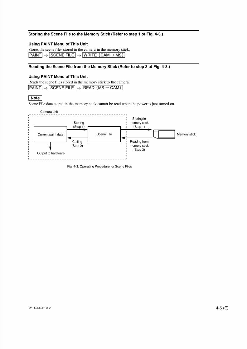
7/14/2019 Bvpe30mmi - Copy
http://slidepdf.com/reader/full/bvpe30mmi-copy 99/136
BVP-E30/E30P M-V1 4-5 (E)
Storing the Scene File to the Memory Stick (Refer to step 1 of Fig. 4-3.)
Using PAINT Menu of This Unit
Stores the scene files stored in the camera in the memory stick.
Reading the Scene File from the Memory Stick (Refer to step 3 of Fig. 4-3.)
Using PAINT Menu of This Unit
Reads the scene files stored in the memory stick to the camera.
nScene File data stored in the memory stick cannot be read when the power is just turned on.
Calling
(Step 2)
Readng from
memory stick
(Step 3)
Storing in
memory stick(Step 1)
Storing(Step 1)
Camera unit
Current paint data Scene File
Output to hardware
Fig. 4-3. Operating Procedure for Scene Files
Memory stick
7/14/2019 Bvpe30mmi - Copy
http://slidepdf.com/reader/full/bvpe30mmi-copy 100/136
4-6 (E) BVP-E30/E30P M-V1
4-5. Reference File
Reference File stores data in the camera and the memory stick.
It also stores in the IC memory card if the MSU (master setup unit) is used. For the details, refer to the
MSU operation manual.
Storing and calling the data are implemented using the setup menu or MSU.
Reference Files stores the differential data taking the factory-setting as 0. Therefore, initializing the
Reference File brings the settings to the same status at factory-setting. If Lens File or OHB File retains the
data, they need to be initialized as well. To initialize data, use the setup menu. You can select whether to
initialize the all file items or only the specified items.
Reference Files can be copied between cameras using the memory stick.
nBefore storing the data in the memory stick, make sure that the LOCK switch on the memory stick is in
OFF position.
Storing (Refer to step 1 of Fig.4-4.)
Using FILE Menu of This Unit
[FILE] → [REFERENCE] → [STORE|FILE]The data will be stored in the camera and the numerical data will be displayed as 0. (Excluding some
items. Refer to Section 4-8. “File Items”.)
With MSU
Press FILE button. Then press [Reference] and press [Ref|Store]. The data will be stored in the
camera and the numerical data will be displayed as 0. (Excluding some items. Refer to Section 4-8. “File
Items”.)
Calling (Refer to step 2 of Fig. 4-4, Fig. 4-1.)
Using PAINT Menu of This Unit
[PAINT] → [SCENE|FILE] → [STANDARD]The temporary paint amount and scene file amount will be cleared and the reference file will be reset to
the state stored in.
With MSU
Press STANDARD button to reset the reference file item to the state stored in.
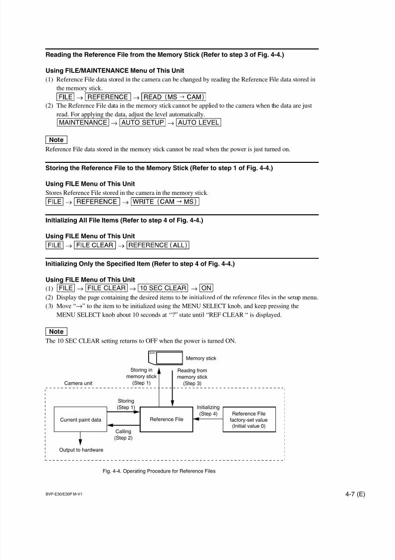
7/14/2019 Bvpe30mmi - Copy
http://slidepdf.com/reader/full/bvpe30mmi-copy 101/136
BVP-E30/E30P M-V1 4-7 (E)
Reading the Reference File from the Memory Stick (Refer to step 3 of Fig. 4-4.)
Using FILE/MAINTENANCE Menu of This Unit
(1) Reference File data stored in the camera can be changed by reading the Reference File data stored in
the memory stick.
(2) The Reference File data in the memory stick cannot be applied to the camera when the data are just
read. For applying the data, adjust the level automatically.
[MAINTENANCE] → [AUTO|SETUP] → [AUTO|LEVEL]
nReference File data stored in the memory stick cannot be read when the power is just turned on.
Storing the Reference File to the Memory Stick (Refer to step 1 of Fig. 4-4.)
Using FILE Menu of This Unit
Stores Reference File stored in the camera in the memory stick.
Initializing All File Items (Refer to step 4 of Fig. 4-4.)
Using FILE Menu of This Unit
Initializing Only the Specified Item (Refer to step 4 of Fig. 4-4.)
Using FILE Menu of This Unit
(1) [FILE] → [FILE|CLEAR] → [10|SEC|CLEAR] → [ON](2) Display the page containing the desired items to be initialized of the reference files in the setup menu.
(3) Move “→” to the item to be initialized using the MENU SELECT knob, and keep pressing the
MENU SELECT knob about 10 seconds at “?” state until “REF CLEAR “ is displayed.
nThe 10 SEC CLEAR setting returns to OFF when the power is turned ON.
Calling
(Step 2)
Readng from
memory stick
(Step 3)
Storing in
memory stick
(Step 1)
Initializing
(Step 4)
Storing
(Step 1)
Camera unit
Current paint data Reference FileReference File
factory-set value(Initial value 0)
Output to hardware
Fig. 4-4. Operating Procedure for Reference Files
Memory stick
7/14/2019 Bvpe30mmi - Copy
http://slidepdf.com/reader/full/bvpe30mmi-copy 102/136
4-8 (E) BVP-E30/E30P M-V1
4-6. Lens File
Lens File stores the data to compensate the differences of the white shading, flare balance, white balance,
which occur when the lens extender is set to ON. It also stores the minimum f-stop value and name of the
lens. Lens File data of up to 16 files can be stored in the camera. The adjustment data can be called by
selecting the Lens File.The Lens File stores the differential data from the Reference File.
mPrior to creating the Lens File, perform the necessary adjustments by using the lens normally used to
create the Reference File.
Adjusting the Lens File Data
(Using a lens not compatible with serial communication)
(1) Mount the lens. Select the file with the same name as the lens mounted from the setup menu. If no
file with the same name as the lens exists, select “NO OFFSET”.
[FILE]→ [LENS|FILE]→ [No.]→ (Select the No.)
(2) Select the name of the lens, and minimum f-stop value.
(3) Set the lens extender to OFF.
(4) Shoot the white pattern, and adjust V modulation R/G/B/Master so that the video level is around
560 mV (80 %) with the lens iris set around F4 and the zoom control in the center of the ring.
(5) Adjust the white balance and flare balance shooting the grayscale chart.
(6) Zooming the lens, and adjust the center marker to a position at which the object does not deviate.*1
(7) Store the data in the lens file.
[FILE]→ [LENS|FILE]→ [STORE|FILE](8) Set the lens extender to ON.
(9) Shoot the white pattern, and adjust V modulation R/G/B/Master so that the video level is around
560 mV (80 %) with the lens iris set around F4 and the zoom control in the center of the ring.
(10) Adjust the white balance and flare balance shooting the grayscale chart.
(11) Zooming the lens, and adjust the center marker to a position at which the object does not deviate. *1
(12) Store the Lens File.
[FILE]→ [LENS|FILE]→ [STORE|FILE]
*1 : The center marker position is stored in the Lens File immediately after the position is aligned and not
when executing the Lens File store.
7/14/2019 Bvpe30mmi - Copy
http://slidepdf.com/reader/full/bvpe30mmi-copy 103/136
BVP-E30/E30P M-V1 4-9 (E)
(For lens compatible with serial communication)
(1) Check that the lens number is No. 17.
(2) Also check that the name of the lens and minimum f-stop value.
(3) Turn on the dynamic shading. *1
(4) Set the lens extender to OFF.
(5) Adjust the white balance and flare balance shooting the grayscale chart.(6) Zooming the lens, and adjust the center marker to a position at which the subject does not move.*2
(7) Store the Lens File.
[FILE]→ [LENS|FILE]→ [STORE|FILE](8) Set the lens extender to ON.
(9) Adjust the white balance and flare balance shooting the grayscale chart.
(10) Zooming the lens, and adjust the center marker to a position at which the subject does not move. *2
(11) Store the Lens File.
[FILE]→ [LENS|FILE]→ [STORE|FILE]
*1 : If using the lens compatible with serial communication with the dynamic shading turned on, you do
not require the V modulation adjustment. Adjust the white shading or V modulation only when the
deviation occurs. In this case, the data will not be stored in the Lens File.
*2 : The center marker position is stored in the Lens File immediately after the position is aligned and not
when executing the Lens File store.
Calling
Using OPERATION Menu of This Unit
Select the Lens File.
[OPERATION] → [LENS|FILE]
Initializing
Using FILE Menu of This Unit
All data of the lens file being currently selected will be initialized to the factory setting values.
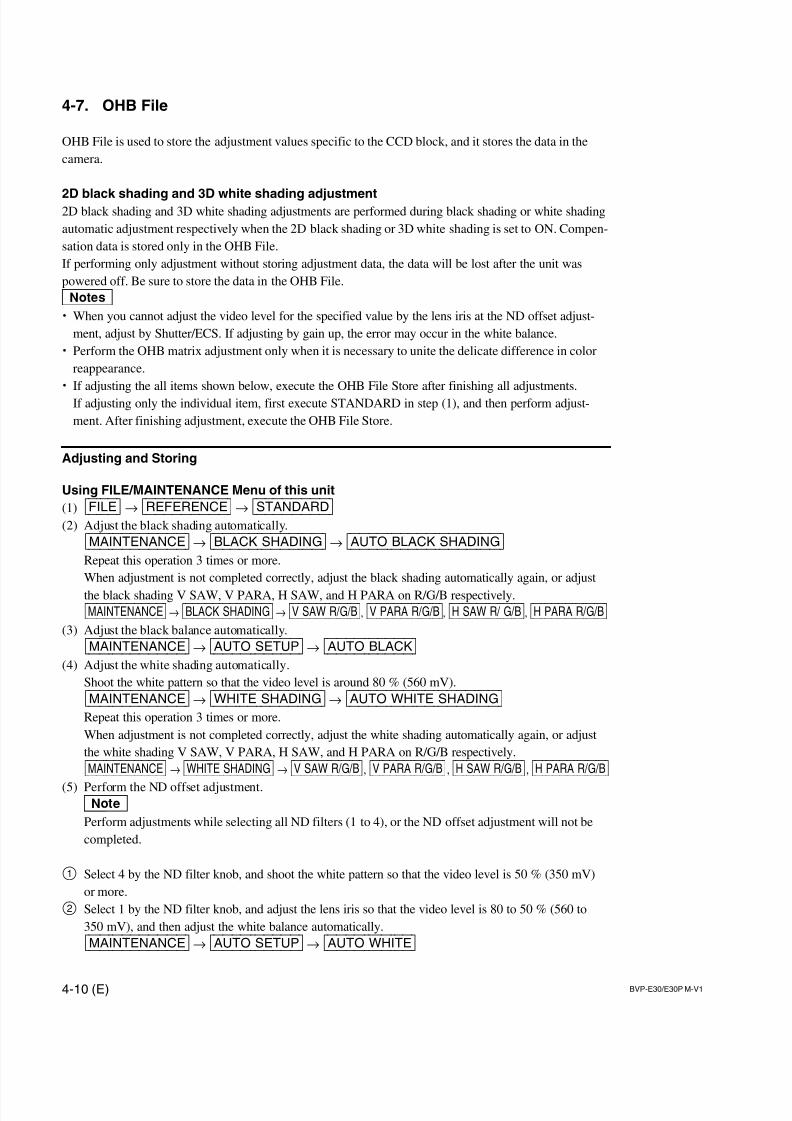
7/14/2019 Bvpe30mmi - Copy
http://slidepdf.com/reader/full/bvpe30mmi-copy 104/136
4-10 (E) BVP-E30/E30P M-V1
4-7. OHB File
OHB File is used to store the adjustment values specific to the CCD block, and it stores the data in the
camera.
2D black shading and 3D white shading adjustment2D black shading and 3D white shading adjustments are performed during black shading or white shading
automatic adjustment respectively when the 2D black shading or 3D white shading is set to ON. Compen-
sation data is stored only in the OHB File.
If performing only adjustment without storing adjustment data, the data will be lost after the unit was
powered off. Be sure to store the data in the OHB File.
m. When you cannot adjust the video level for the specified value by the lens iris at the ND offset adjust-
ment, adjust by Shutter/ECS. If adjusting by gain up, the error may occur in the white balance.
. Perform the OHB matrix adjustment only when it is necessary to unite the delicate difference in color
reappearance.
. If adjusting the all items shown below, execute the OHB File Store after finishing all adjustments.
If adjusting only the individual item, first execute STANDARD in step (1), and then perform adjust-
ment. After finishing adjustment, execute the OHB File Store.
Adjusting and Storing
Using FILE/MAINTENANCE Menu of this unit
(1) [FILE] → [REFERENCE] → [STANDARD](2) Adjust the black shading automatically.
[MAINTENANCE] → [BLACK|SHADING] → [AUTO|BLACK|SHADING]Repeat this operation 3 times or more.
When adjustment is not completed correctly, adjust the black shading automatically again, or adjust
the black shading V SAW, V PARA, H SAW, and H PARA on R/G/B respectively.
[MAINTENANCE] → [BLACK|SHADING] → [V|SAW|R/G/B], [V|PARA|R/G/B], [H|SAW|R/|G/B], [H|PARA|R/G/B](3) Adjust the black balance automatically.
[MAINTENANCE] → [AUTO|SETUP] → [AUTO|BLACK](4) Adjust the white shading automatically.
Shoot the white pattern so that the video level is around 80 % (560 mV).
[MAINTENANCE] → [WHITE|SHADING] → [AUTO|WHITE|SHADING]Repeat this operation 3 times or more.
When adjustment is not completed correctly, adjust the white shading automatically again, or adjust
the white shading V SAW, V PARA, H SAW, and H PARA on R/G/B respectively.
[MAINTENANCE] → [WHITE|SHADING] → [V|SAW|R/G/B], [V|PARA|R/G/B], [H|SAW|R/G/B], [H|PARA|R/G/B]
(5) Perform the ND offset adjustment.nPerform adjustments while selecting all ND filters (1 to 4), or the ND offset adjustment will not be
completed.
1 Select 4 by the ND filter knob, and shoot the white pattern so that the video level is 50 % (350 mV)
or more.
2 Select 1 by the ND filter knob, and adjust the lens iris so that the video level is 80 to 50 % (560 to
350 mV), and then adjust the white balance automatically.
[MAINTENANCE] → [AUTO|SETUP] → [AUTO|WHITE]
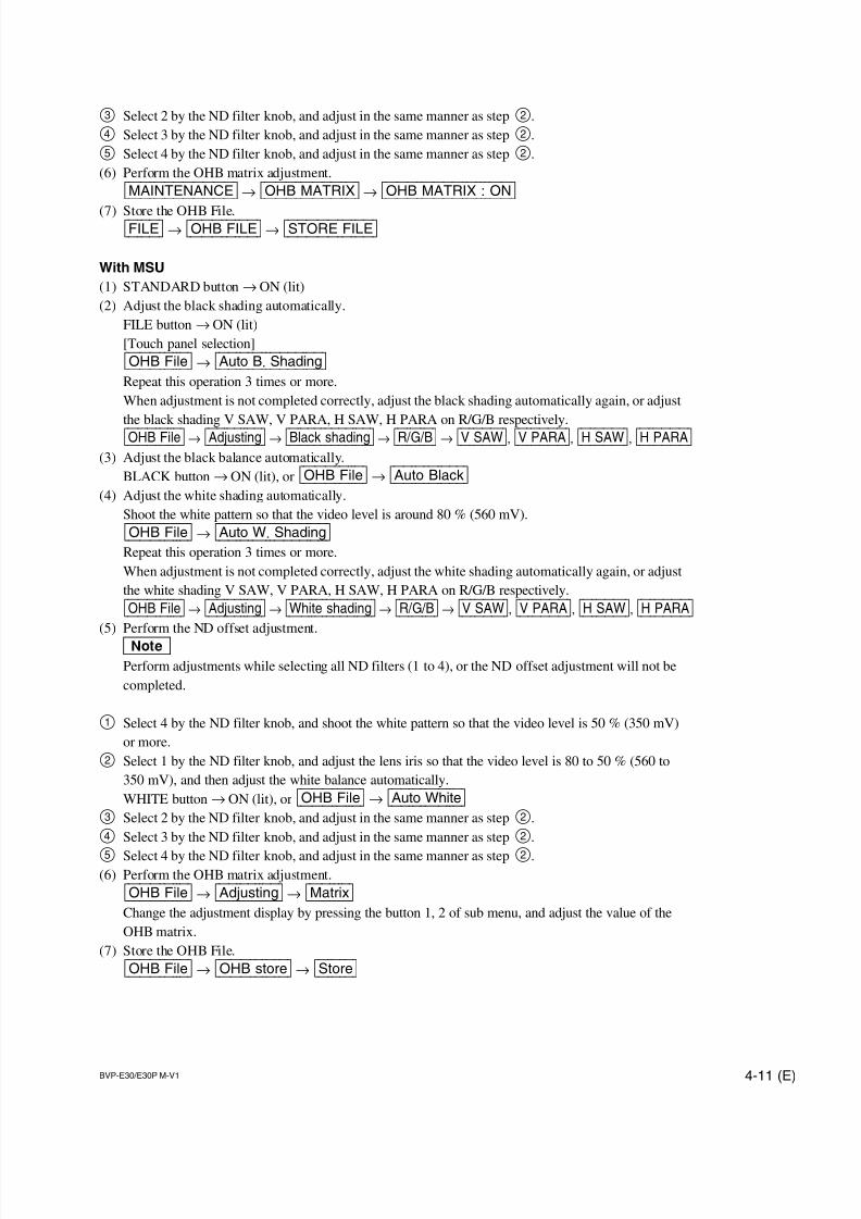
7/14/2019 Bvpe30mmi - Copy
http://slidepdf.com/reader/full/bvpe30mmi-copy 105/136
BVP-E30/E30P M-V1 4-11 (E)
3 Select 2 by the ND filter knob, and adjust in the same manner as step2.
4 Select 3 by the ND filter knob, and adjust in the same manner as step2.
5 Select 4 by the ND filter knob, and adjust in the same manner as step2.
(6) Perform the OHB matrix adjustment.
[MAINTENANCE] → [OHB|MATRIX] → [OHB|MATRIX|:|ON]
(7) Store the OHB File.[FILE] → [OHB|FILE] → [STORE|FILE]
With MSU
(1) STANDARD button→ ON (lit)
(2) Adjust the black shading automatically.
FILE button→ ON (lit)
[Touch panel selection]
[OHB|File] → [Auto|B.|Shading]Repeat this operation 3 times or more.
When adjustment is not completed correctly, adjust the black shading automatically again, or adjust
the black shading V SAW, V PARA, H SAW, H PARA on R/G/B respectively.
[OHB|File] → [Adjusting] → [Black|shading] → [R/G/B] → [V|SAW], [V|PARA], [H|SAW], [H|PARA](3) Adjust the black balance automatically.
BLACK button→ ON (lit), or [OHB|File] → [Auto|Black](4) Adjust the white shading automatically.
Shoot the white pattern so that the video level is around 80 % (560 mV).
[OHB|File] → [Auto|W.|Shading]Repeat this operation 3 times or more.
When adjustment is not completed correctly, adjust the white shading automatically again, or adjust
the white shading V SAW, V PARA, H SAW, H PARA on R/G/B respectively.
[OHB|File] → [Adjusting] → [White|shading] → [R/G/B] → [V|SAW], [V|PARA], [H|SAW], [H|PARA](5) Perform the ND offset adjustment.
nPerform adjustments while selecting all ND filters (1 to 4), or the ND offset adjustment will not be
completed.
1 Select 4 by the ND filter knob, and shoot the white pattern so that the video level is 50 % (350 mV)
or more.
2 Select 1 by the ND filter knob, and adjust the lens iris so that the video level is 80 to 50 % (560 to
350 mV), and then adjust the white balance automatically.
WHITE button→ ON (lit), or [OHB|File] → [Auto|White]3 Select 2 by the ND filter knob, and adjust in the same manner as step2.
4 Select 3 by the ND filter knob, and adjust in the same manner as step2.
5 Select 4 by the ND filter knob, and adjust in the same manner as step2.(6) Perform the OHB matrix adjustment.
[OHB|File] → [Adjusting] → [Matrix]Change the adjustment display by pressing the button 1, 2 of sub menu, and adjust the value of the
OHB matrix.
(7) Store the OHB File.
[OHB|File] → [OHB|store] → [Store]
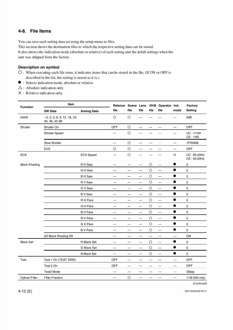
7/14/2019 Bvpe30mmi - Copy
http://slidepdf.com/reader/full/bvpe30mmi-copy 106/136
4-12 (E) BVP-E30/E30P M-V1
FunctionItem Refence Scene Lens OHB Operator Ind. Factory
SW Data Analog Data file file file file file mode Setting
GAIN _3, 0, 3, 6, 9, 12, 18, 24, O O — — — — 0dB
30, 36, 42 dB
Shutter Shutter On OFF O — — — — OFF
Shutter Speed — O — — — — UC : 1/100
CE : 1/60
Slow Shutter — O — — — — 1FRAME
EVS O O — — — — OFF
ECS ECS Speed — O — — — X UC : 60.00Hz
CE : 50.00Hz
Black Shading R H Saw — — — O — 0
G H Saw — — — O — 0
B H Saw — — — O — 0
R V Saw — — — O — 0
G V Saw — — — O — 0
B V Saw — — — O — 0
R H Para — — — O — 0
G H Para — — — O — 0
B H Para — — — O — 0
R V Para — — — O — 0
G V Para — — — O — 0
B V Para — — — O — 02D Black Shading Off — — — — — — ON
Black Set R Black Set — — — O — 0
G Black Set — — — O — 0
B Black Set — — — O — 0
Test Test 1 On (TEST SAW) OFF — — — — — OFF
Test 2 On OFF — — — — — OFF
Test2 Mode — — — — — — 3Step
Optical Filter Filter Posit ion — O — — — — 1/1B (WS only)
(Continued)
4-8. File Items
You can save each setting data set using the setup menu in files.
This section shows the destination files to which the respective setting data can be stored.
It also shows the indication mode (absolute or relative) of each setting and the defalt settings when the
unit was shipped from the factory.
Description on symbol
O : When executing each file store, it indicates items that can be stored in the file. (If ON or OFF is
described in the list, the setting is stored as it is.)
: Selects indication mode, absolute or relative.
T : Absolute indication only.
X : Relative indication only.
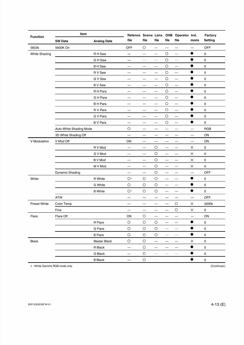
7/14/2019 Bvpe30mmi - Copy
http://slidepdf.com/reader/full/bvpe30mmi-copy 107/136
BVP-E30/E30P M-V1 4-13 (E)
FunctionItem Refence Scene Lens OHB Operator Ind. Factory
SW Data Analog Data file file file file file mode Setting
5600k 5600K On OFF O — — — — OFF
White Shading R H Saw — — — O — 0
G H Saw — — — O — 0
B H Saw — — — O — 0
R V Saw — — — O — 0
G V Saw — — — O — 0
B V Saw — — — O — 0
R H Para — — — O — 0
G H Para — — — O — 0
B H Para — — — O — 0
R V Para — — — O — 0
G V Para — — — O — 0
B V Para — — — O — 0
Auto White Shading Mode O — — — — — RGB
3D White Shading Off — — — — — — ON
V Modulation V Mod Off ON — — — — — ON
R V Mod — — O — — X 0
G V Mod — — O — — X 0
B V Mod — — O — — X 0
M V Mod — — O — — X 0
Dynamic Shading — — O — — — OFF
White R White O * O O — — 0
G White O O O — — 0
B White O * O O — — 0
ATW — — — — — — OFF
Preset White Color Temp — — — — O X 3200k
Fine — — — — O X 0
Flare Flare Off ON O — — — — ON
R Flare O O O — — 0
G Flare O O O — — 0
B Flare O O O — — 0
Black Master Black O O — — — X 0
R Black — O — — — 0
G Black — O — — — 0
B Black — O — — — 0
* : White Gamma RGB mode only (Continued)
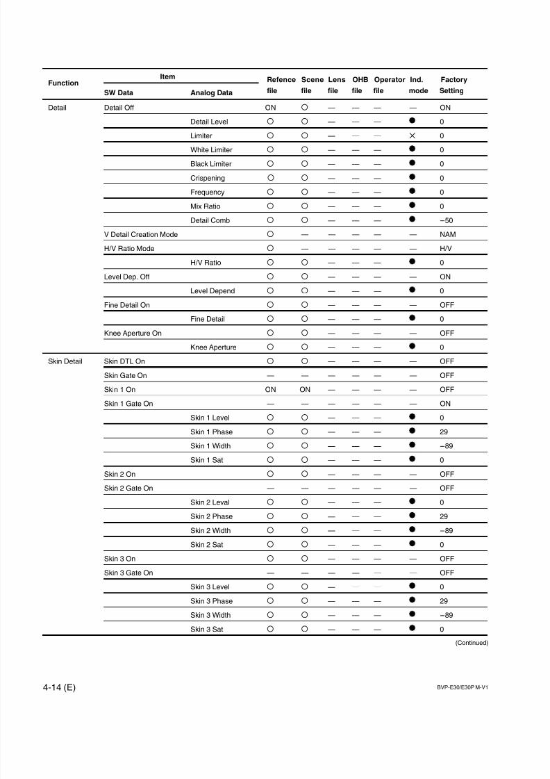
7/14/2019 Bvpe30mmi - Copy
http://slidepdf.com/reader/full/bvpe30mmi-copy 108/136
4-14 (E) BVP-E30/E30P M-V1
FunctionItem Refence Scene Lens OHB Operator Ind. Factory
SW Data Analog Data file file file file file mode Setting
Detail Detail Off ON O — — — — ON
Detail Level O O — — — 0
Limiter O O — — — X 0
White Limiter O O — — — 0
Black Limiter O O — — — 0
Crispening O O — — — 0
Frequency O O — — — 0
Mix Ratio O O — — — 0
Detail Comb O O — — — _50
V Detail Creation Mode O — — — — — NAM
H/V Ratio Mode O — — — — — H/V
H/V Ratio O O — — — 0
Level Dep. Off O O — — — — ON
Level Depend O O — — — 0
Fine Detail On O O — — — — OFF
Fine Detail O O — — — 0
Knee Aperture On O O — — — — OFF
Knee Aperture O O — — — 0
Skin Detail Skin DTL On O O — — — — OFF
Skin Gate On — — — — — — OFF
Skin 1 On ON ON — — — — OFF
Skin 1 Gate On — — — — — — ON
Skin 1 Level O O — — — 0
Skin 1 Phase O O — — — 29
Skin 1 Width O O — — — _89
Skin 1 Sat O O — — — 0
Skin 2 On O O — — — — OFF
Skin 2 Gate On — — — — — — OFF
Skin 2 Leval O O — — — 0
Skin 2 Phase O O — — — 29
Skin 2 Width O O — — — _89
Skin 2 Sat O O — — — 0
Skin 3 On O O — — — — OFF
Skin 3 Gate On — — — — — — OFF
Skin 3 Level O O — — — 0
Skin 3 Phase O O — — — 29
Skin 3 Width O O — — — _89
Skin 3 Sat O O — — — 0
(Continued)
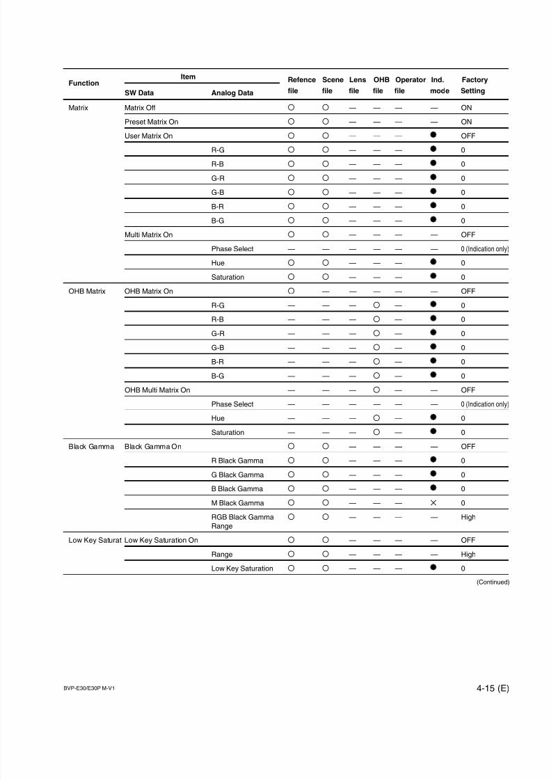
7/14/2019 Bvpe30mmi - Copy
http://slidepdf.com/reader/full/bvpe30mmi-copy 109/136
BVP-E30/E30P M-V1 4-15 (E)
FunctionItem Refence Scene Lens OHB Operator Ind. Factory
SW Data Analog Data file file file file file mode Setting
Matrix Matrix Off O O — — — — ON
Preset Matrix On O O — — — — ON
User Matrix On O O — — — OFF
R-G O O — — — 0
R-B O O — — — 0
G-R O O — — — 0
G-B O O — — — 0
B-R O O — — — 0
B-G O O — — — 0
Multi Matrix On O O — — — — OFF
Phase Select — — — — — — 0 (Indication only)
Hue O O — — — 0
Saturation O O — — — 0
OHB Matrix OHB Matrix On O — — — — — OFF
R-G — — — O — 0
R-B — — — O — 0
G-R — — — O — 0
G-B — — — O — 0
B-R — — — O — 0
B-G — — — O — 0
OHB Multi Matrix On — — — O — — OFF
Phase Select — — — — — — 0 (Indication only)
Hue — — — O — 0
Saturation — — — O — 0
Black Gamma Black Gamma On O O — — — — OFF
R Black Gamma O O — — — 0
G Black Gamma O O — — — 0
B Black Gamma O O — — — 0
M Black Gamma O O — — — X 0
RGB Black Gamma O O — — — — High
Range
Low Key Saturat Low Key Saturation On O O — — — — OFF
Range O O — — — — High
Low Key Saturation O O — — — 0
(Continued)
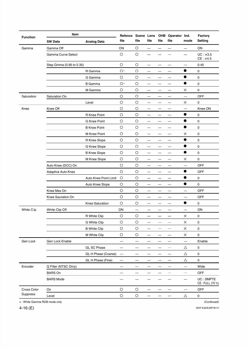
7/14/2019 Bvpe30mmi - Copy
http://slidepdf.com/reader/full/bvpe30mmi-copy 110/136
4-16 (E) BVP-E30/E30P M-V1
FunctionItem Refence Scene Lens OHB Operator Ind. Factory
SW Data Analog Data file file file file file mode Setting
Gamma Gamma Off ON O — — — — ON
Gamma Curve Select O O — — — — UC : x3.5
CE : x4.5
Step Gmma (0.95 to 0.35) O O — — — — 0.45
R Gamma O * O — — — 0
G Gamma O O — — — 0
B Gamma O * O — — — 0
M Gamma O O — — — X 0
Saturation Saturation On O O — — — — OFF
Level O O — — — X 0
Knee Knee Off O O — — — — Knee ON
R Knee Point O O — — — 0
G Knee Point O O — — — 0
B Knee Point O O — — — 0
M Knee Point O O — — — X 0
R Knee Slope O O — — — 0
G Knee Slope O O — — — 0
B Knee Slope O O — — — 0
M Knee Slope O O — — — X 0
Auto Knee (DCC) On O O — — — — OFF
Adaptive Auto Knee O O — — — OFF
Auto Knee Point Limit O O — — — 0
Auto Knee Slope O O — — — 0
Knee Max On O O — — — — OFF
Knee Sauration On O O — — — — OFF
Knee Saturation O O — — — 0
White Clip White Clip Off ON — — — — — ON
R White Clip O O — — — X 0
G White Clip O O — — — X 0
B White Clip O O — — — X 0
M White Clip O O — — — X 0
Gen Lock Gen Lock Enable — — — — — — Enable
GL SC Phase — — — — — T 0
GL H Phase (Coarse) — — — — — T 0
GL H Phase (Fine) — — — — — T 0
Encoder Q Filter (NTSC Only) — — — — — — Wide
BARS On — — — — — — OFF
BARS Mode — — — — — — UC : SMPTE
CE : FULL (75 %)
Cross Color On O O — — — — OFF
SuppressLevel O O — — — T 0
* : White Gamma RGB mode only (Continued)
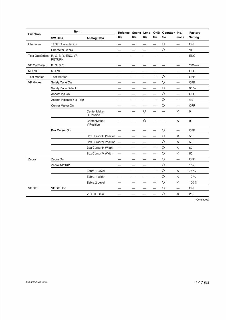
7/14/2019 Bvpe30mmi - Copy
http://slidepdf.com/reader/full/bvpe30mmi-copy 111/136
BVP-E30/E30P M-V1 4-17 (E)
FunctionItem Refence Scene Lens OHB Operator Ind. Factory
SW Data Analog Data file file file file file mode Setting
Character TEST Character On — — — — O — ON
Character SYNC — — — — O — VF
Test Out Select R, G, B, Y, ENC, VF, — — — — — — ENCRETURN
VF Out Select R, G, B, Y — — — — — — Y/Color
MIX VF MIX VF — — — — — — OFF
Test Marker Test Marker — — — — O — OFF
VF Marker Safety Zone On — — — — O — OFF
Safety Zone Select — — — — O — 90 %
Aspect Ind On — — — — O — OFF
Aspect Indicator 4:3-15:9 — — — — O — 4:3
Center Maker On — — — — O — OFF
Center Maker — — O — — X 0H Position
Center Maker — — O — — X 0
V Position
Box Cursor On — — — — O — OFF
Box Cursor H Position — — — — O X 50
Box Cursor V Position — — — — O X 50
Box Cursor H Width — — — — O X 50
Box Cursor V Width — — — — O X 50
Zebra Zebra On — — — — O — OFF
Zebra 1/2/1&2 — — — — O — 1&2
Zebra 1 Level — — — — O X 75 %
Zebra 1 Width — — — — O X 10 %
Zebra 2 Level — — — — O X 100 %
VF DTL VF DTL On — — — — O — ON
VF DTL Gain — — — — O X 25
(Continued)
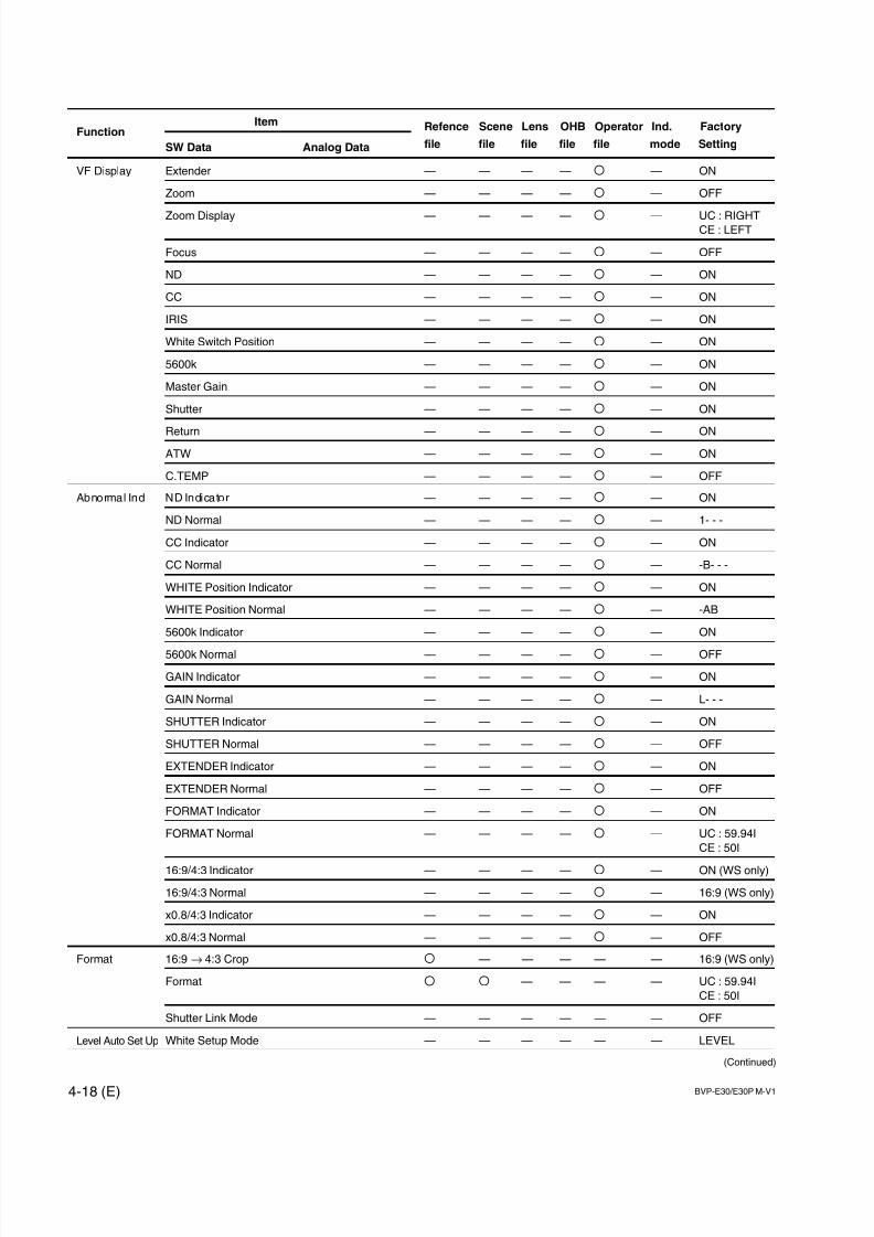
7/14/2019 Bvpe30mmi - Copy
http://slidepdf.com/reader/full/bvpe30mmi-copy 112/136
4-18 (E) BVP-E30/E30P M-V1
FunctionItem Refence Scene Lens OHB Operator Ind. Factory
SW Data Analog Data file file file file file mode Setting
VF Display Extender — — — — O — ON
Zoom — — — — O — OFF
Zoom Display — — — — O — UC : RIGHTCE : LEFT
Focus — — — — O — OFF
ND — — — — O — ON
CC — — — — O — ON
IRIS — — — — O — ON
White Switch Position — — — — O — ON
5600k — — — — O — ON
Master Gain — — — — O — ON
Shutter — — — — O — ON
Return — — — — O — ON
ATW — — — — O — ON
C.TEMP — — — — O — OFF
Abnormal Ind ND Indicator — — — — O — ON
ND Normal — — — — O — 1- - -
CC Indicator — — — — O — ON
CC Normal — — — — O — -B- - -
WHITE Position Indicator — — — — O — ON
WHITE Position Normal — — — — O — -AB
5600k Indicator — — — — O — ON
5600k Normal — — — — O — OFF
GAIN Indicator — — — — O — ON
GAIN Normal — — — — O — L- - -
SHUTTER Indicator — — — — O — ON
SHUTTER Normal — — — — O — OFF
EXTENDER Indicator — — — — O — ON
EXTENDER Normal — — — — O — OFF
FORMAT Indicator — — — — O — ON
FORMAT Normal — — — — O — UC : 59.94I
CE : 50I
16:9/4:3 Indicator — — — — O — ON (WS only)
16:9/4:3 Normal — — — — O — 16:9 (WS only)
x0.8/4:3 Indicator — — — — O — ON
x0.8/4:3 Normal — — — — O — OFF
Format 16:9 → 4:3 Crop O — — — — — 16:9 (WS only)
Format O O — — — — UC : 59.94I
CE : 50I
Shutter Link Mode — — — — — — OFF
Level Auto Set Up White Setup Mode — — — — — — LEVEL
(Continued)
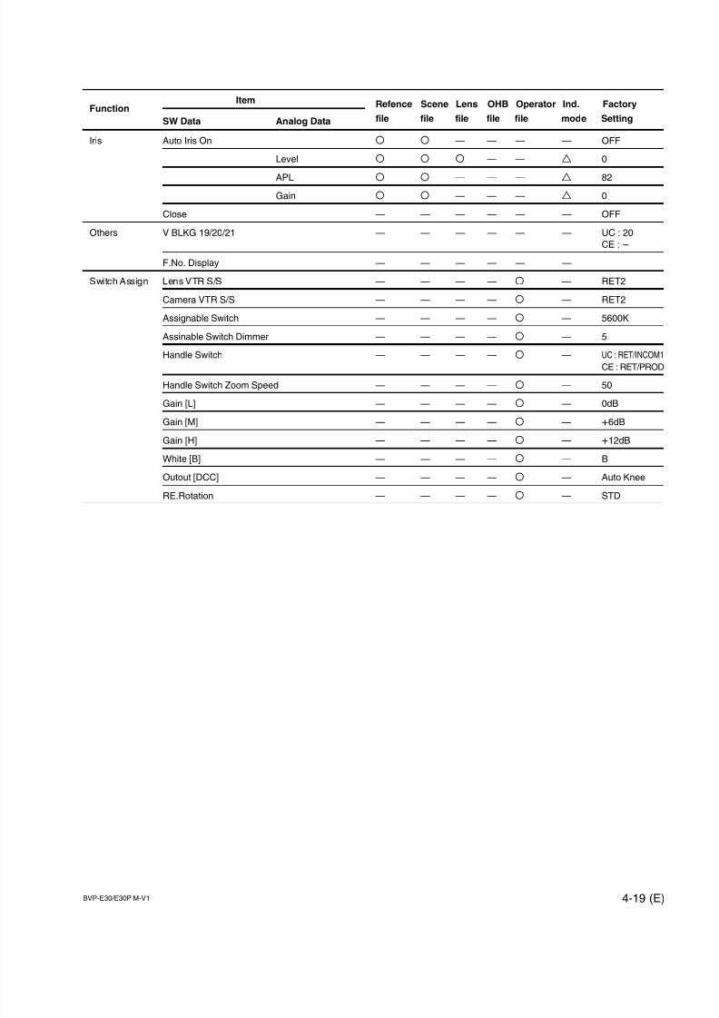
7/14/2019 Bvpe30mmi - Copy
http://slidepdf.com/reader/full/bvpe30mmi-copy 113/136
BVP-E30/E30P M-V1 4-19 (E)
FunctionItem Refence Scene Lens OHB Operator Ind. Factory
SW Data Analog Data file file file file file mode Setting
Iris Auto Iris On O O — — — — OFF
Level O O O — — T 0
APL O O — — — T 82
Gain O O — — — T 0
Close — — — — — — OFF
Others V BLKG 19/20/21 — — — — — — UC : 20
CE : _
F.No. Display — — — — — —
Switch Assign Lens VTR S/S — — — — O — RET2
Camera VTR S/S — — — — O — RET2
Assignable Switch — — — — O — 5600K
Assinable Switch Dimmer — — — — O — 5
Handle Switch — — — — O — UC : RET/INCOM1CE : RET/PROD
Handle Switch Zoom Speed — — — — O — 50
Gain [L] — — — — O — 0dB
Gain [M] — — — — O — +6dB
Gain [H] — — — — O — +12dB
White [B] — — — — O — B
Outout [DCC] — — — — O — Auto Knee
RE.Rotation — — — — O — STD

7/14/2019 Bvpe30mmi - Copy
http://slidepdf.com/reader/full/bvpe30mmi-copy 114/136
7/14/2019 Bvpe30mmi - Copy
http://slidepdf.com/reader/full/bvpe30mmi-copy 115/136
BVP-E30/E30P M-V1 5-1 (E)
Section 5
Electrical Alignment
5-1. Preparation
5-1-1. Equipment Required
Tools
. Extension board EX-464 (Sony part No. : A-8318-864-A)
. Pattern box (PTB-500, 90-240 Vac) (Sony part No. : J-6029-140-B)
. Grayscale chart (4:3, transparent) (Sony part No. : J-6026-130-B)
. Grayscale chart (16:9, transparent) (Sony part No. : J-6394-080-A)
. Grayscale chart (4:3, reflective) (Commercially available, Refer to Section 5-1-5)
. Flexible card wire (30P, 140 mm) (2 pieces) (Sony part No. : 1-823-429-11)
. EX Harness (3 pieces) (Sony part No. : 1-961-653-21)
Equipment
. Digital oscilloscope: Tektronix TDS460A or equivalent
. Waveform monitor/Vectorscope: Tektronix 1750 (for NTSC)/1751 (for PAL) or equivalent
. Monochrome monitor (Horizontal resolution; 900 TV lines or more)
. Frequency counter: Advantest TR5821 or equivalent
. Digital voltmeter: Advantest TR6845 or equivalent
Peripheral equipment
. Camera control unit: CCU-550D/550DP
CCU-700A/700AP
CCU-900/900P
. Camera adaptor: CA-570/570P
CA-950/950P
. Viewfinder: BVF-10/10CE/20W/20WCE/C10W
. Master setup unit: MSU-700A/750
. AC adapter: AC-550/550CE
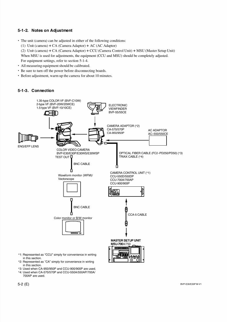
7/14/2019 Bvpe30mmi - Copy
http://slidepdf.com/reader/full/bvpe30mmi-copy 116/136
5-2 (E) BVP-E30/E30P M-V1
ENG/EFP LENS
OPTICAL FIBER CABLE (FC2–PD250/PD50) (*3)TRIAX CABLE (*4)
CCA-5 CABLE
AC ADAPTORAC–550/550CE
1.35-type COLOR VF (BVF-C10W)2-type VF (BVF-20W/20WCE)1.5-type VF (BVF-10/10CE)
COLOR VIDEO CAMERABVP-E30/E30P/E30WS/E30WSP
ELECTRONICVIEWFINDER
BVF-55/55CE
CAMERA ADAPTOR (*2)CA-570/570PCA-950/950P
MASTER SETUP UNITMSU-700MASTER SETUP UNITMSU-700MASTER SETUP UNITMSU-700A/750
CAMERA CONTROL UNIT (*1)CCU-550D/550DPCCU-700A/700APCCU-900/900P
*1: Represented as “CCU” simply for convenience in wirtingin this section.
*2: Represented as “CA” simply for convenience in wirtingin this section.
*3: Used when CA-950/950P and CCU-900/900P are used.*4: Used when CA-570/570P and CCU-550A/550AP/700A/
700AP are used.
Waveform monitor (WFM)/ Vectorscope
Color monitor or B/W monitor
BNC CABLE
TEST OUT
BNC CABLE
5-1-2. Notes on Adjustment
. The unit (camera) can be adjusted in either of the following conditions:
(1) Unit (camera) + CA (Camera Adaptor) + AC (AC Adaptor)
(2) Unit (camera) + CA (Camera Adaptor) + CCU (Camera Control Unit) + MSU (Master Setup Unit)
When MSU is used for adjustments, the equipment (CCU and MSU) should be completely adjusted.For equipment settings, refer to section 5-1-4.
. All measuring equipment should be calibrated.
. Be sure to turn off the power before disconnecting boards.
. Before adjustment, warm up the camera for about 10 minutes.
5-1-3. Connection
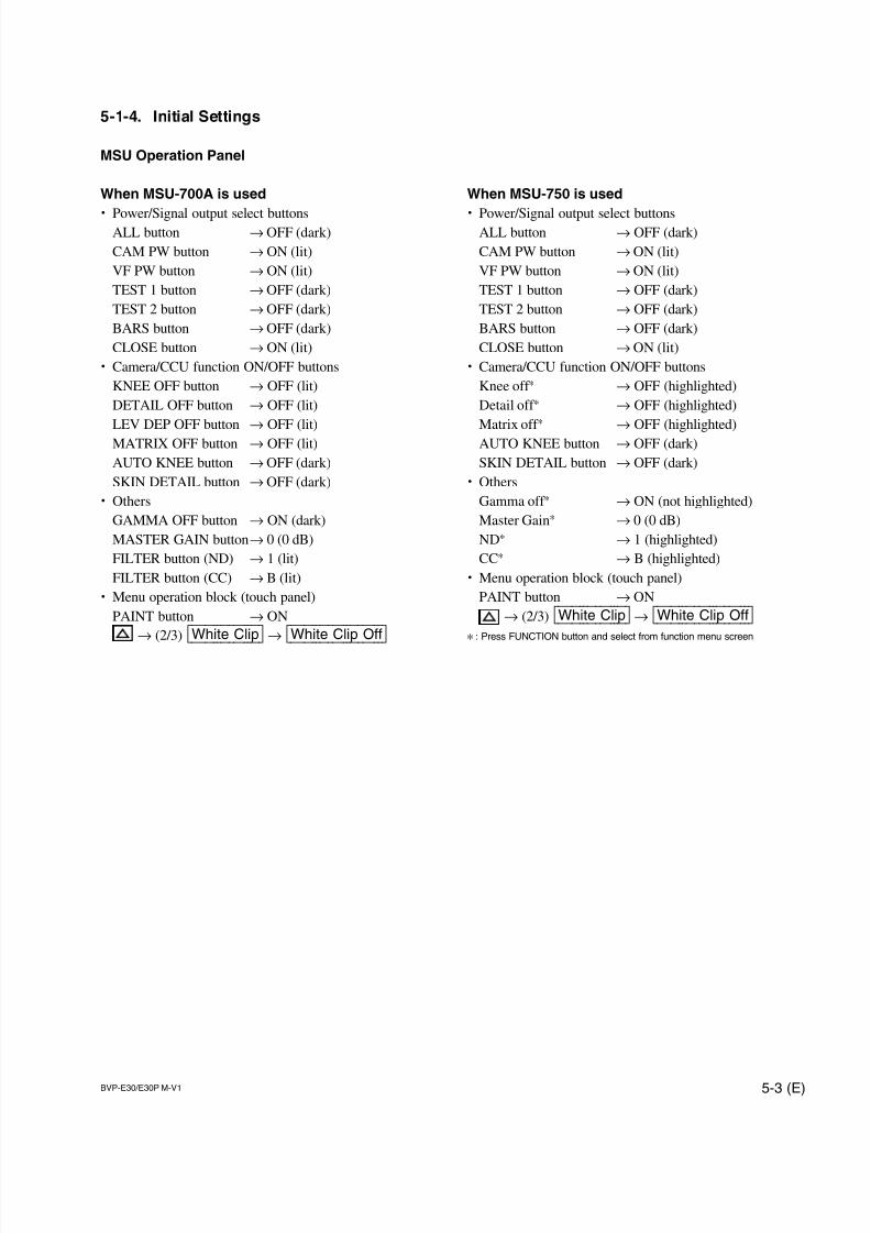
7/14/2019 Bvpe30mmi - Copy
http://slidepdf.com/reader/full/bvpe30mmi-copy 117/136
BVP-E30/E30P M-V1 5-3 (E)
When MSU-750 is used
. Power/Signal output select buttonsALL button → OFF (dark)
CAM PW button → ON (lit)
VF PW button → ON (lit)
TEST 1 button → OFF (dark)
TEST 2 button → OFF (dark)
BARS button → OFF (dark)
CLOSE button → ON (lit)
. Camera/CCU function ON/OFF buttons
Knee off * → OFF (highlighted)
Detail off * → OFF (highlighted)
Matrix off * → OFF (highlighted)
AUTO KNEE button → OFF (dark)
SKIN DETAIL button → OFF (dark)
. Others
Gamma off * → ON (not highlighted)
Master Gain* → 0 (0 dB)
ND* → 1 (highlighted)
CC* → B (highlighted)
. Menu operation block (touch panel)
PAINT button → ON
→ (2/3) [White|Clip] → [White|Clip|Off]* : Press FUNCTION button and select from function menu screen
5-1-4. Initial Settings
MSU Operation Panel
When MSU-700A is used
. Power/Signal output select buttonsALL button → OFF (dark)
CAM PW button → ON (lit)
VF PW button → ON (lit)
TEST 1 button → OFF (dark)
TEST 2 button → OFF (dark)
BARS button → OFF (dark)
CLOSE button → ON (lit)
. Camera/CCU function ON/OFF buttons
KNEE OFF button → OFF (lit)
DETAIL OFF button → OFF (lit)
LEV DEP OFF button → OFF (lit)
MATRIX OFF button → OFF (lit)
AUTO KNEE button → OFF (dark)
SKIN DETAIL button → OFF (dark)
. Others
GAMMA OFF button → ON (dark)
MASTER GAIN button→ 0 (0 dB)
FILTER button (ND) → 1 (lit)
FILTER button (CC) → B (lit)
. Menu operation block (touch panel)
PAINT button → ON
→ (2/3) [White|Clip] → [White|Clip|Off]
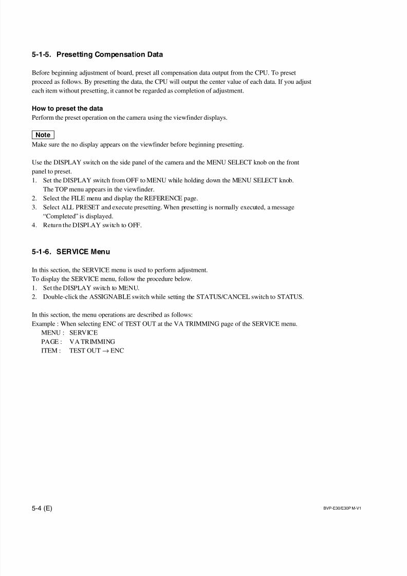
7/14/2019 Bvpe30mmi - Copy
http://slidepdf.com/reader/full/bvpe30mmi-copy 118/136
5-4 (E) BVP-E30/E30P M-V1
5-1-5. Presetting Compensation Data
Before beginning adjustment of board, preset all compensation data output from the CPU. To preset
proceed as follows. By presetting the data, the CPU will output the center value of each data. If you adjust
each item without presetting, it cannot be regarded as completion of adjustment.
How to preset the data
Perform the preset operation on the camera using the viewfinder displays.
nMake sure the no display appears on the viewfinder before beginning presetting.
Use the DISPLAY switch on the side panel of the camera and the MENU SELECT knob on the front
panel to preset.
1. Set the DISPLAY switch from OFF to MENU while holding down the MENU SELECT knob.
The TOP menu appears in the viewfinder.
2. Select the FILE menu and display the REFERENCE page.
3. Select ALL PRESET and execute presetting. When presetting is normally executed, a message
“Completed” is displayed.
4. Return the DISPLAY switch to OFF.
5-1-6. SERVICE Menu
In this section, the SERVICE menu is used to perform adjustment.
To display the SERVICE menu, follow the procedure below.
1. Set the DISPLAY switch to MENU.
2. Double-click the ASSIGNABLE switch while setting the STATUS/CANCEL switch to STATUS.
In this section, the menu operations are described as follows:
Example : When selecting ENC of TEST OUT at the VA TRIMMING page of the SERVICE menu.
MENU : SERVICE
PAGE : VA TRIMMING
ITEM : TEST OUT→ ENC
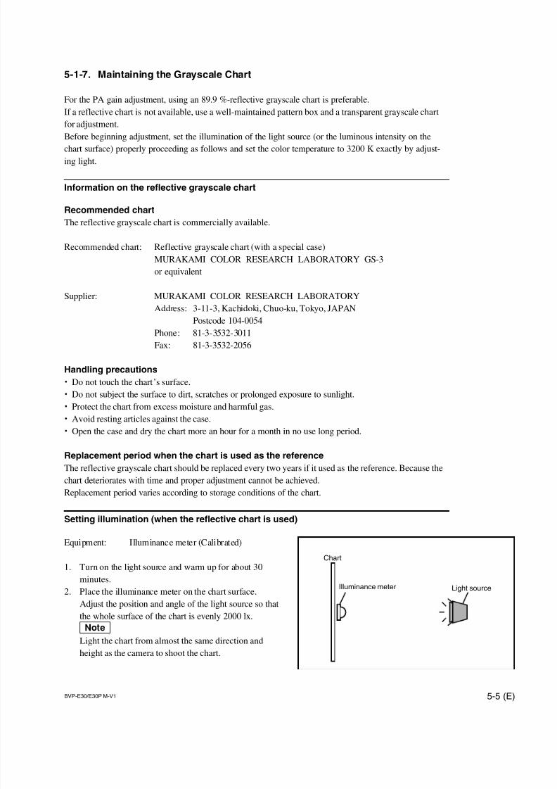
7/14/2019 Bvpe30mmi - Copy
http://slidepdf.com/reader/full/bvpe30mmi-copy 119/136
BVP-E30/E30P M-V1 5-5 (E)
Light source
Chart
Illuminance meter
5-1-7. Maintaining the Grayscale Chart
For the PA gain adjustment, using an 89.9 %-reflective grayscale chart is preferable.
If a reflective chart is not available, use a well-maintained pattern box and a transparent grayscale chart
for adjustment.
Before beginning adjustment, set the illumination of the light source (or the luminous intensity on thechart surface) properly proceeding as follows and set the color temperature to 3200 K exactly by adjust-
ing light.
Information on the reflective grayscale chart
Recommended chart
The reflective grayscale chart is commercially available.
Recommended chart: Reflective grayscale chart (with a special case)
MURAKAMI COLOR RESEARCH LABORATORY GS-3
or equivalent
Supplier: MURAKAMI COLOR RESEARCH LABORATORY
Address: 3-11-3, Kachidoki, Chuo-ku, Tokyo, JAPAN
Postcode 104-0054
Phone: 81-3-3532-3011
Fax: 81-3-3532-2056
Handling precautions
. Do not touch the chart’s surface.
. Do not subject the surface to dirt, scratches or prolonged exposure to sunlight.
. Protect the chart from excess moisture and harmful gas.
. Avoid resting articles against the case.
. Open the case and dry the chart more an hour for a month in no use long period.
Replacement period when the chart is used as the reference
The reflective grayscale chart should be replaced every two years if it used as the reference. Because the
chart deteriorates with time and proper adjustment cannot be achieved.
Replacement period varies according to storage conditions of the chart.
Setting illumination (when the reflective chart is used)
Equipment: Illuminance meter (Calibrated)
1. Turn on the light source and warm up for about 30
minutes.
2. Place the illuminance meter on the chart surface.
Adjust the position and angle of the light source so that
the whole surface of the chart is evenly 2000 lx.
nLight the chart from almost the same direction and
height as the camera to shoot the chart.
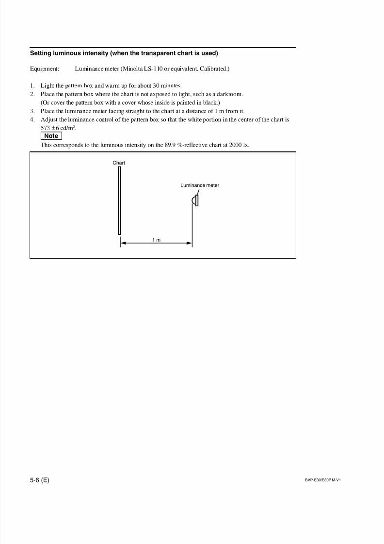
7/14/2019 Bvpe30mmi - Copy
http://slidepdf.com/reader/full/bvpe30mmi-copy 120/136
5-6 (E) BVP-E30/E30P M-V1
Chart
Luminance meter
1 m
Setting luminous intensity (when the transparent chart is used)
Equipment: Luminance meter (Minolta LS-110 or equivalent. Calibrated.)
1. Light the pattern box and warm up for about 30 minutes.
2. Place the pattern box where the chart is not exposed to light, such as a darkroom.(Or cover the pattern box with a cover whose inside is painted in black.)
3. Place the luminance meter facing straight to the chart at a distance of 1 m from it.
4. Adjust the luminance control of the pattern box so that the white portion in the center of the chart is
573 ±6 cd/m2.
nThis corresponds to the luminous intensity on the 89.9 %-reflective chart at 2000 lx.
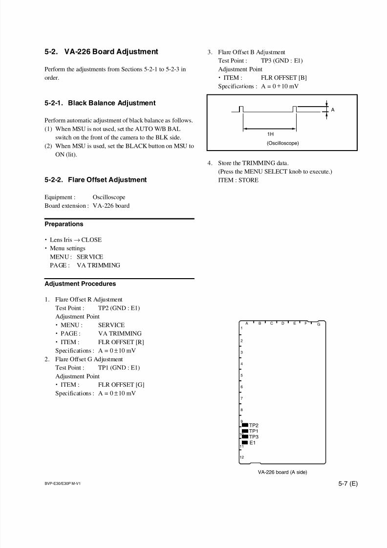
7/14/2019 Bvpe30mmi - Copy
http://slidepdf.com/reader/full/bvpe30mmi-copy 121/136
BVP-E30/E30P M-V1 5-7 (E)
TP1TP2
TP3E1
A B C D E F G1
2
3
4
5
6
7
8
9
10
11
12
VA-226 board (A side)
A
1H
(Oscilloscope)
3. Flare Offset B Adjustment
Test Point : TP3 (GND : E1)
Adjustment Point
. ITEM : FLR OFFSET [B]
Specifications : A = 0 ±10 mV
4. Store the TRIMMING data.
(Press the MENU SELECT knob to execute.)
ITEM : STORE
5-2. VA-226 Board Adjustment
Perform the adjustments from Sections 5-2-1 to 5-2-3 in
order.
5-2-1. Black Balance Adjustment
Perform automatic adjustment of black balance as follows.
(1) When MSU is not used, set the AUTO W/B BAL
switch on the front of the camera to the BLK side.
(2) When MSU is used, set the BLACK button on MSU to
ON (lit).
5-2-2. Flare Offset Adjustment
Equipment : Oscilloscope
Board extension : VA-226 board
Preparations
. Lens Iris→ CLOSE
. Menu settings
MENU : SERVICE
PAGE : VA TRIMMING
Adjustment Procedures
1. Flare Offset R Adjustment
Test Point : TP2 (GND : E1)
Adjustment Point
. MENU : SERVICE
. PAGE : VA TRIMMING
. ITEM : FLR OFFSET [R]
Specifications : A = 0 ±10 mV
2. Flare Offset G Adjustment
Test Point : TP1 (GND : E1)
Adjustment Point
. ITEM : FLR OFFSET [G]Specifications : A = 0 ±10 mV
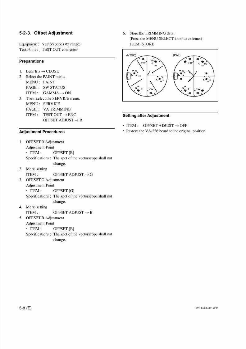
7/14/2019 Bvpe30mmi - Copy
http://slidepdf.com/reader/full/bvpe30mmi-copy 122/136
5-8 (E) BVP-E30/E30P M-V1
R MG
CYG
YL
B
R MG
CYG
YL
B
(NTSC) (PAL)
5-2-3. Offset Adjustment
Equipment : Vectorscope (x5 range)
Test Point : TEST OUT connector
Preparations
1. Lens Iris → CLOSE
2. Select the PAINT menu.
MENU : PAINT
PAGE : SW STATUS
ITEM : GAMMA→ ON
3. Then, select the SERVICE menu.
MENU : SERVICE
PAGE : VA TRIMMING
ITEM : TEST OUT→ ENC
OFFSET ADJUST→ R
Adjustment Procedures
1. OFFSET R Adjustment
Adjustment Point
. ITEM : OFFSET [R]
Specifications : The spot of the vectorscope shall not
change.
2. Menu setting
ITEM : OFFSET ADJUST→ G
3. OFFSET G Adjustment
Adjustment Point
. ITEM : OFFSET [G]
Specifications : The spot of the vectorscope shall not
change.
4. Menu setting
ITEM : OFFSET ADJUST→ B
5. OFFSET B Adjustment
Adjustment Point
. ITEM : OFFSET [B]
Specifications : The spot of the vectorscope shall not
change.
6. Store the TRIMMING data.
(Press the MENU SELECT knob to execute.)
ITEM: STORE
Setting after Adjustment
. ITEM : OFFSET ADJUST→ OFF
. Restore the VA-226 board to the original position.
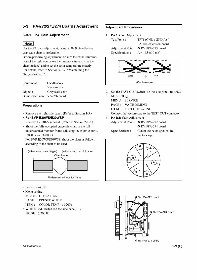
7/14/2019 Bvpe30mmi - Copy
http://slidepdf.com/reader/full/bvpe30mmi-copy 123/136
BVP-E30/E30P M-V1 5-9 (E)
5-3. PA-272/273/274 Boards Adjustment
5-3-1. PA Gain Adjustment
n
For the PA gain adjustment, using an 89.9 %-reflectivegrayscale chart is preferable.
Before performing adjustment, be sure to set the illumina-
tion of the light source (or the luminous intensity on the
chart surface) and to set the color temperature exactly.
For details, refer to Section 5-1-7. “Maintaining the
Grayscale Chart”.
Equipment : Oscilloscope
Vectorscope
Object : Grayscale chart
Board extension : VA-226 board
Preparations
. Remove the right side panel. (Refer to Section 1-5.)
. For BVP-E30WS/E30WSP
Remove the DR-536 board. (Refer to Section 2-1-3.)
. Shoot the fully occupied grayscale chart in the full
underscanned monitor frame adjusting the zoom control.
(2000 lx and 3200 K)
For BVP-E30WS/E30WSP, shoot the chart as follows
according to the chart to be used.
. Lens Iris→ F11
. Menu setting
MENU : OPERATIONPAGE : PRESET WHITE
ITEM : COLOR TEMP→ 3200k
. WHITE BAL switch (on the side panel) →
PRESET (3200 K)
(When using the 4:3 type)
Chart frame
(When using the 16:9 type)
Underscanned monitor frame
Adjustment Procedures
1. PA G Gain Adjustment
Test Point : TP71 (GND : GND A) /
EX-464 extension board
Adjustment Point : 1 RV1/PA-273 boardSpecifications : A = 165 ±10 mV
2. Set the TEST OUT switch (on the side panel) to ENC.
3. Menu setting
MENU : SERVICE
PAGE : VA TRIMMING
ITEM : TEST OUT→ ENC
Connect the vectorscope to the TEST OUT connector.
4. PA R/B Gain Adjustment
Adjustment Point : 1 RV1/PA-272 board
1 RV1/PA-274 board
Specifications : Center the beam spot on the
vectorscope.
RMG
CYG
YL
B
10uS50m BWL
A
(Oscilloscope)
1
1
1
RV1/PA-272 board
RV1/PA-273 board
RV1/PA-274 board
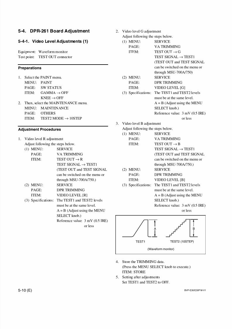
7/14/2019 Bvpe30mmi - Copy
http://slidepdf.com/reader/full/bvpe30mmi-copy 124/136
5-10 (E) BVP-E30/E30P M-V1
B
TEST1 TEST2 (10STEP)
A
(Waveform monitor)
2. Video level G adjustment
Adjust following the steps below.
(1) MENU: SERVICE
PAGE: VA TRIMMING
ITEM: TEST OUT→ G
TEST SIGNAL→ TEST1(TEST OUT and TEST SIGNAL
can be switched on the menu or
through MSU-700A/750)
(2) MENU: SERVICE
PAGE: DPR TRIMMING
ITEM: VIDEO LEVEL [G]
(3) Specifications: The TEST1 and TEST2 levels
must be at the same level.
A = B (Adjust using the MENU
SELECT knob.)
Reference value: 3 mV (0.5 IRE)
or less
3. Video level B adjustment
Adjust following the steps below.
(1) MENU: SERVICE
PAGE: VA TRIMMING
ITEM: TEST OUT→ B
TEST SIGNAL→ TEST1
(TEST OUT and TEST SIGNAL
can be switched on the menu or
through MSU-700A/750.)
(2) MENU: SERVICE
PAGE: DPR TRIMMING
ITEM: VIDEO LEVEL [B]
(3) Specifications: The TEST1 and TEST2 levels
must be at the same level.
A = B (Adjust using the MENU
SELECT knob.)
Reference value: 3 mV (0.5 IRE)
or less
4. Store the TRIMMING data.
(Press the MENU SELECT knob to execute.)
ITEM: STORE
5. Setting after adjustments
Set TEST1 and TEST2 to OFF.
5-4. DPR-261 Board Adjustment
5-4-1. Video Level Adjustments (1)
Equipment: Waveform monitor
Test point: TEST OUT connector
Preparations
1. Select the PAINT menu.
MENU: PAINT
PAGE: SW STATUS
ITEM: GAMMA→ OFF
KNEE→ OFF
2. Then, select the MAINTENANCE menu.
MENU: MAINTENANCE
PAGE: OTHERS
ITEM: TEST2 MODE→ 10STEP
Adjustment Procedures
1. Video level R adjustment
Adjust following the steps below.
(1) MENU: SERVICE
PAGE: VA TRIMMING
ITEM: TEST OUT→ R
TEST SIGNAL→ TEST1
(TEST OUT and TEST SIGNAL
can be switched on the menu or
through MSU-700A/750.)
(2) MENU: SERVICE
PAGE: DPR TRIMMING
ITEM: VIDEO LEVEL [R]
(3) Specifications: The TEST1 and TEST2 levels
must be at the same level.
A = B (Adjust using the MENU
SELECT knob.)
Reference value: 3 mV (0.5 IRE)
or less
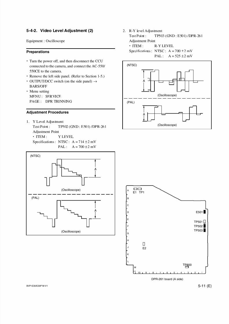
7/14/2019 Bvpe30mmi - Copy
http://slidepdf.com/reader/full/bvpe30mmi-copy 125/136
BVP-E30/E30P M-V1 5-11 (E)
TP501
TP502TP503
TP1
E501
E1
1110 9 8 7 6 5 4 3 2 1
M
L
K
J
H
G
F
E
D
C
B
A
DPR-261 board (A side)
TP800
E2
5-4-2. Video Level Adjustment (2)
Equipment : Oscilloscope
Preparations
. Turn the power off, and then disconnect the CCU
connected to the camera, and connect the AC-550/
550CE to the camera.
. Remove the left side panel. (Refer to Section 1-5.)
. OUTPUT/DCC switch (on the side panel) →
BARS/OFF
. Menu setting
MENU : SERVICE
PAGE : DPR TRINNING
Adjustment Procedures
1. Y Level Adjustment
Test Point : TP502 (GND : E501) /DPR-261
Adjustment Point
. ITEM : Y LEVEL
Specifications : NTSC : A = 714 ±2 mV
PAL : A = 700 ±2 mV
A
A
(NTSC)
(PAL)
(Oscilloscope)
(Oscilloscope)
2. R-Y level Adjustment
Test Point : TP503 (GND : E501) /DPR-261
Adjustment Point
. ITEM : R-Y LEVEL
Specifications : NTSC : A = 700 ±2 mV
PAL : A = 525 ±2 mV
A
(NTSC)
(PAL)
A
(Oscilloscope)
(Oscilloscope)
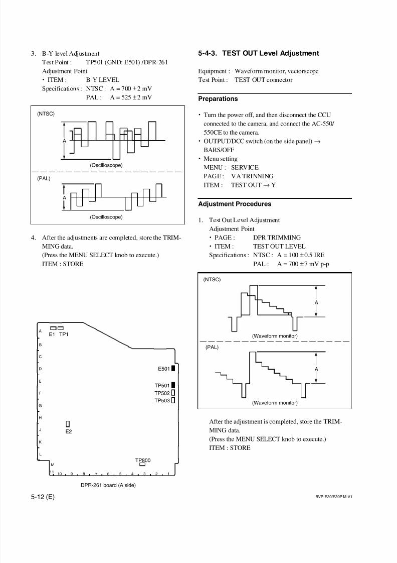
7/14/2019 Bvpe30mmi - Copy
http://slidepdf.com/reader/full/bvpe30mmi-copy 126/136
5-12 (E) BVP-E30/E30P M-V1
TP501
TP502TP503
TP1
E501
E1
1110 9 8 7 6 5 4 3 2 1
M
L
K
J
H
G
F
E
D
C
B
A
DPR-261 board (A side)
TP800
E2
5-4-3. TEST OUT Level Adjustment
Equipment : Waveform monitor, vectorscope
Test Point : TEST OUT connector
Preparations
. Turn the power off, and then disconnect the CCU
connected to the camera, and connect the AC-550/
550CE to the camera.
. OUTPUT/DCC switch (on the side panel) →
BARS/OFF
. Menu setting
MENU : SERVICE
PAGE : VA TRINNING
ITEM : TEST OUT→ Y
Adjustment Procedures
1. Test Out Level Adjustment
Adjustment Point
. PAGE : DPR TRIMMING
. ITEM : TEST OUT LEVEL
Specifications : NTSC : A = 100 ±0.5 IRE
PAL : A = 700 ±7 mV p-p
After the adjustment is completed, store the TRIM-
MING data.
(Press the MENU SELECT knob to execute.)
ITEM : STORE
A
A
(NTSC)
(PAL)
(Waveform monitor)
(Waveform monitor)
3. B-Y level Adjustment
Test Point : TP501 (GND: E501) /DPR-261
Adjustment Point
. ITEM : B-Y LEVEL
Specifications : NTSC : A = 700 ±2 mV
PAL : A = 525 ±2 mV
4. After the adjustments are completed, store the TRIM-
MING data.
(Press the MENU SELECT knob to execute.)
ITEM : STORE
A
A
(NTSC)
(PAL)
(Oscilloscope)
(Oscilloscope)
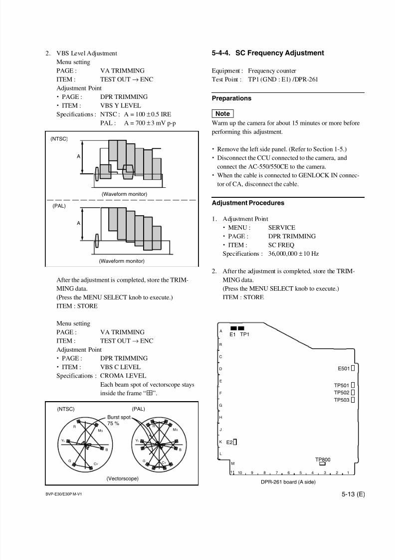
7/14/2019 Bvpe30mmi - Copy
http://slidepdf.com/reader/full/bvpe30mmi-copy 127/136
BVP-E30/E30P M-V1 5-13 (E)
RMG
B
CYG
YL
RMG
CYG
YL
B
(NTSC) (PAL)
(Vectorscope)
Burst spot
75 %
TP501
TP502TP503
TP1E1
11 10 9 8 7 6 5 4 3 2 1
M
L
K
J
H
G
F
E
D
C
B
A
DPR-261 board (A side)
E501
TP800
E2
2. VBS Level Adjustment
Menu setting
PAGE : VA TRIMMING
ITEM : TEST OUT→ ENC
Adjustment Point
. PAGE : DPR TRIMMING
. ITEM : VBS Y LEVEL
Specifications : NTSC : A = 100 ±0.5 IRE
PAL : A = 700 ±3 mV p-p
After the adjustment is completed, store the TRIM-
MING data.
(Press the MENU SELECT knob to execute.)
ITEM : STORE
Menu setting
PAGE : VA TRIMMING
ITEM : TEST OUT→ ENC
Adjustment Point
. PAGE : DPR TRIMMING
. ITEM : VBS C LEVEL
Specifications : CROMA LEVEL
Each beam spot of vectorscope stays
inside the frame “4”.
A
A
(NTSC)
(PAL)
(Waveform monitor)
(Waveform monitor)
5-4-4. SC Frequency Adjustment
Equipment : Frequency counter
Test Point : TP1 (GND : E1) /DPR-261
Preparations
nWarm up the camera for about 15 minutes or more before
performing this adjustment.
. Remove the left side panel. (Refer to Section 1-5.)
. Disconnect the CCU connected to the camera, and
connect the AC-550/550CE to the camera.
. When the cable is connected to GENLOCK IN connec-
tor of CA, disconnect the cable.
Adjustment Procedures
1. Adjustment Point
. MENU : SERVICE
. PAGE : DPR TRIMMING
. ITEM : SC FREQ
Specifications : 36,000,000 ±10 Hz
2. After the adjustment is completed, store the TRIM-
MING data.
(Press the MENU SELECT knob to execute.)
ITEM : STORE
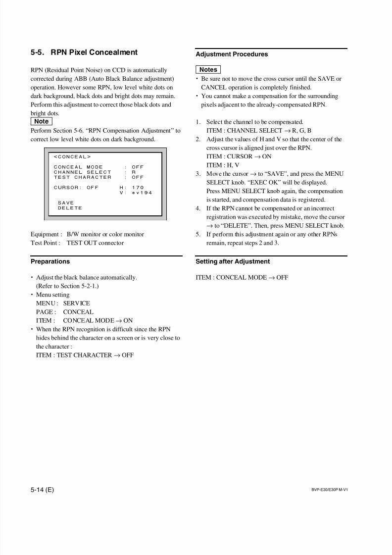
7/14/2019 Bvpe30mmi - Copy
http://slidepdf.com/reader/full/bvpe30mmi-copy 128/136
5-14 (E) BVP-E30/E30P M-V1
5-5. RPN Pixel Concealment
RPN (Residual Point Noise) on CCD is automatically
corrected during ABB (Auto Black Balance adjustment)
operation. However some RPN, low level white dots on
dark background, black dots and bright dots may remain.Perform this adjustment to correct those black dots and
bright dots.
nPerform Section 5-6. “RPN Compensation Adjustment” to
correct low level white dots on dark background.
Equipment : B/W monitor or color monitor
Test Point : TEST OUT connector
Preparations
. Adjust the black balance automatically.
(Refer to Section 5-2-1.)
. Menu setting
MENU : SERVICE
PAGE : CONCEAL
ITEM : CONCEAL MODE→ ON
. When the RPN recognition is difficult since the RPN
hides behind the character on a screen or is very close to
the character :
ITEM : TEST CHARACTER → OFF
Adjustment Procedures
m. Be sure not to move the cross cursor until the SAVE or
CANCEL operation is completely finished.
. You cannot make a compensation for the surroundingpixels adjacent to the already-compensated RPN.
1. Select the channel to be compensated.
ITEM : CHANNEL SELECT → R, G, B
2. Adjust the values of H and V so that the center of the
cross cursor is aligned just over the RPN.
ITEM : CURSOR → ON
ITEM : H, V
3. Move the cursor→ to “SAVE”, and press the MENU
SELECT knob. “EXEC OK” will be displayed.
Press MENU SELECT knob again, the compensation
is started, and compensation data is registered.
4. If the RPN cannot be compensated or an incorrect
registration was executed by mistake, move the cursor
→ to “DELETE”. Then, press MENU SELECT knob.
5. If perform this adjustment again or any other RPNs
remain, repeat steps 2 and 3.
Setting after Adjustment
ITEM : CONCEAL MODE→ OFF
<CONCEAL>
CONCEAL MODE : OFF
CHANNEL SELECT : R
TEST CHARACTER : OFF
CURSOR: OFF H: 170
V: ev194
SAVE
DELETE
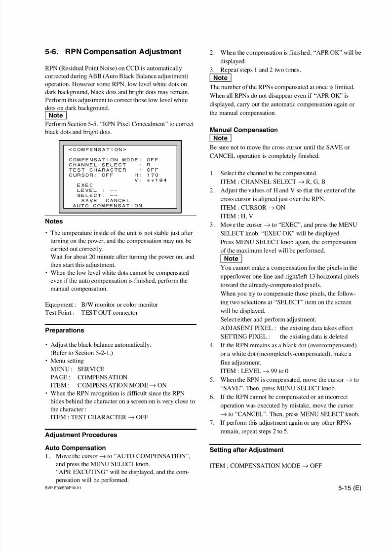
7/14/2019 Bvpe30mmi - Copy
http://slidepdf.com/reader/full/bvpe30mmi-copy 129/136
BVP-E30/E30P M-V1 5-15 (E)
5-6. RPN Compensation Adjustment
RPN (Residual Point Noise) on CCD is automatically
corrected during ABB (Auto Black Balance adjustment)
operation. However some RPN, low level white dots on
dark background, black dots and bright dots may remain.
Perform this adjustment to correct those low level white
dots on dark background.
nPerform Section 5-5. “RPN Pixel Concealment” to correct
black dots and bright dots.
Notes
. The temperature inside of the unit is not stable just after
turning on the power, and the compensation may not be
carried out correctly.
Wait for about 20 minute after turning the power on, and
then start this adjustment.
. When the low level white dots cannot be compensated
even if the auto compensation is finished, perform the
manual compensation.
Equipment : B/W monitor or color monitor
Test Point : TEST OUT connector
Preparations
. Adjust the black balance automatically.
(Refer to Section 5-2-1.)
. Menu setting
MENU : SERVICE
PAGE : COMPENSATION
ITEM : COMPENSATION MODE→
ON. When the RPN recognition is difficult since the RPN
hides behind the character on a screen on is very close to
the character :
ITEM : TEST CHARACTER → OFF
Adjustment Procedures
Auto Compensation
1. Move the cursor→ to “AUTO COMPENSATION”,
and press the MENU SELECT knob.
“APR EXCUTING” will be displayed, and the com-
pensation will be performed.
2. When the compensation is finished, “APR OK” will be
displayed.
3. Repeat steps 1 and 2 two times.
nThe number of the RPNs compensated at once is limited.
When all RPNs do not disappear even if “APR OK” isdisplayed, carry out the automatic compensation again or
the manual compensation.
Manual Compensation
nBe sure not to move the cross cursor until the SAVE or
CANCEL operation is completely finished.
1. Select the channel to be compensated.
ITEM : CHANNEL SELECT → R, G, B
2. Adjust the values of H and V so that the center of the
cross cursor is aligned just over the RPN.
ITEM : CURSOR → ON
ITEM : H, V
3. Move the cursor→ to “EXEC”, and press the MENU
SELECT knob. “EXEC OK” will be displayed.
Press MENU SELECT knob again, the compensation
of the maximum level will be performed.
nYou cannot make a compensation for the pixels in the
upper/lower one line and right/left 13 horizontal pixels
toward the already-compensated pixels.
When you try to compensate those pixels, the follow-
ing two selections at “SELECT” item on the screen
will be displayed.
Select either and perform adjustment.
ADJASENT PIXEL : the existing data takes effect
SETTING PIXEL : the existing data is deleted
4. If the RPN remains as a black dot (overcompensated)
or a white dot (incompletely-compensated), make a
fine adjustment.
ITEM : LEVEL→ 99 to 0
5. When the RPN is compensated, move the cursor→ to
“SAVE”. Then, press MENU SELECT knob.6. If the RPN cannot be compensated or an incorrect
operation was executed by mistake, move the cursor
→ to “CANCEL”. Then, press MENU SELECT knob.
7. If perform this adjustment again or any other RPNs
remain, repeat steps 2 to 5.
Setting after Adjustment
ITEM : COMPENSATION MODE→ OFF
<COMPENSATION>
COMPENSATION MODE: OFF
CHANNEL SELECT : R
TEST CHARACTER : OFF
CURSOR: OFF H: 170
V: ev194
EXEC
LEVEL : --
SELECT: --
SAVE CANCEL
AUTO COMPENSATION
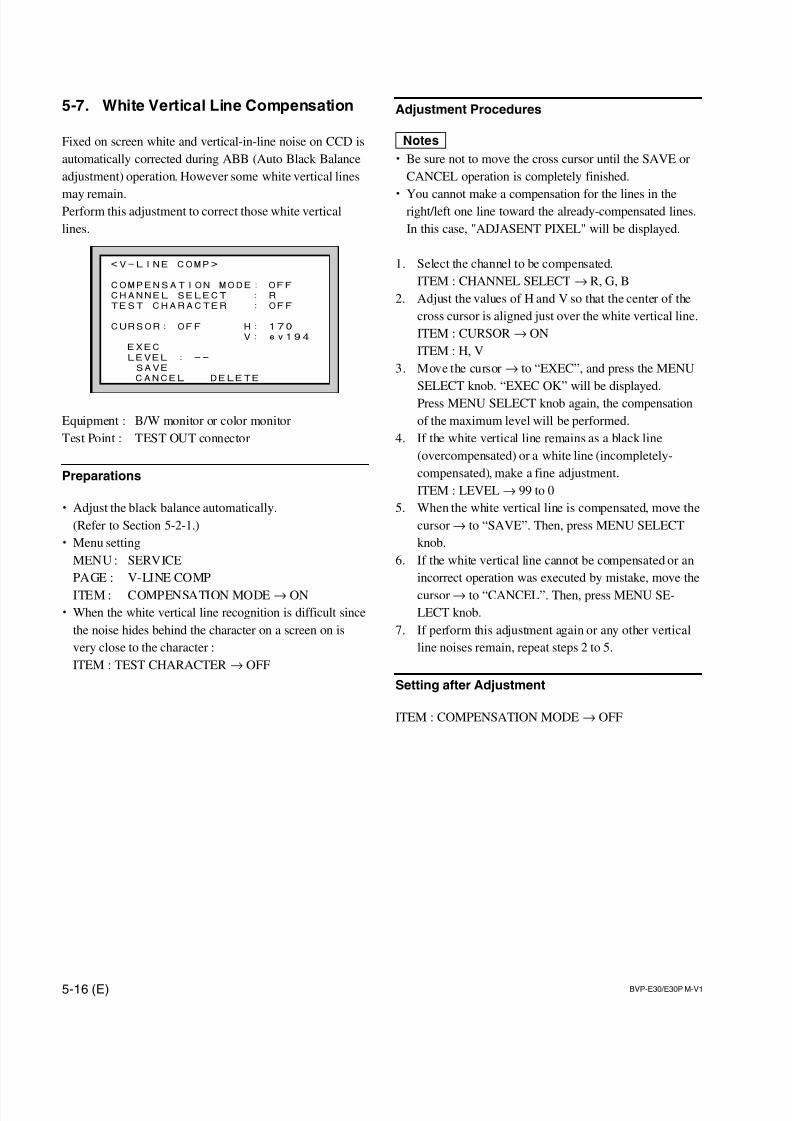
7/14/2019 Bvpe30mmi - Copy
http://slidepdf.com/reader/full/bvpe30mmi-copy 130/136
5-16 (E) BVP-E30/E30P M-V1
5-7. White Vertical Line Compensation
Fixed on screen white and vertical-in-line noise on CCD is
automatically corrected during ABB (Auto Black Balance
adjustment) operation. However some white vertical lines
may remain.Perform this adjustment to correct those white vertical
lines.
Equipment : B/W monitor or color monitor
Test Point : TEST OUT connector
Preparations
. Adjust the black balance automatically.
(Refer to Section 5-2-1.)
. Menu setting
MENU : SERVICE
PAGE : V-LINE COMP
ITEM : COMPENSATION MODE→ ON
. When the white vertical line recognition is difficult since
the noise hides behind the character on a screen on is
very close to the character :
ITEM : TEST CHARACTER → OFF
Adjustment Procedures
m. Be sure not to move the cross cursor until the SAVE or
CANCEL operation is completely finished.
. You cannot make a compensation for the lines in theright/left one line toward the already-compensated lines.
In this case, "ADJASENT PIXEL" will be displayed.
1. Select the channel to be compensated.
ITEM : CHANNEL SELECT → R, G, B
2. Adjust the values of H and V so that the center of the
cross cursor is aligned just over the white vertical line.
ITEM : CURSOR → ON
ITEM : H, V
3. Move the cursor→ to “EXEC”, and press the MENU
SELECT knob. “EXEC OK” will be displayed.
Press MENU SELECT knob again, the compensation
of the maximum level will be performed.
4. If the white vertical line remains as a black line
(overcompensated) or a white line (incompletely-
compensated), make a fine adjustment.
ITEM : LEVEL→ 99 to 0
5. When the white vertical line is compensated, move the
cursor → to “SAVE”. Then, press MENU SELECT
knob.
6. If the white vertical line cannot be compensated or an
incorrect operation was executed by mistake, move the
cursor → to “CANCEL”. Then, press MENU SE-
LECT knob.
7. If perform this adjustment again or any other vertical
line noises remain, repeat steps 2 to 5.
Setting after Adjustment
ITEM : COMPENSATION MODE → OFF
<V-LINE COMP>
COMPENSATION MODE: OFF
CHANNEL SELECT : R
TEST CHARACTER : OFF
CURSOR: OFF H: 170
V: ev194
EXEC
LEVEL : --
SAVE
CANCEL DELETE
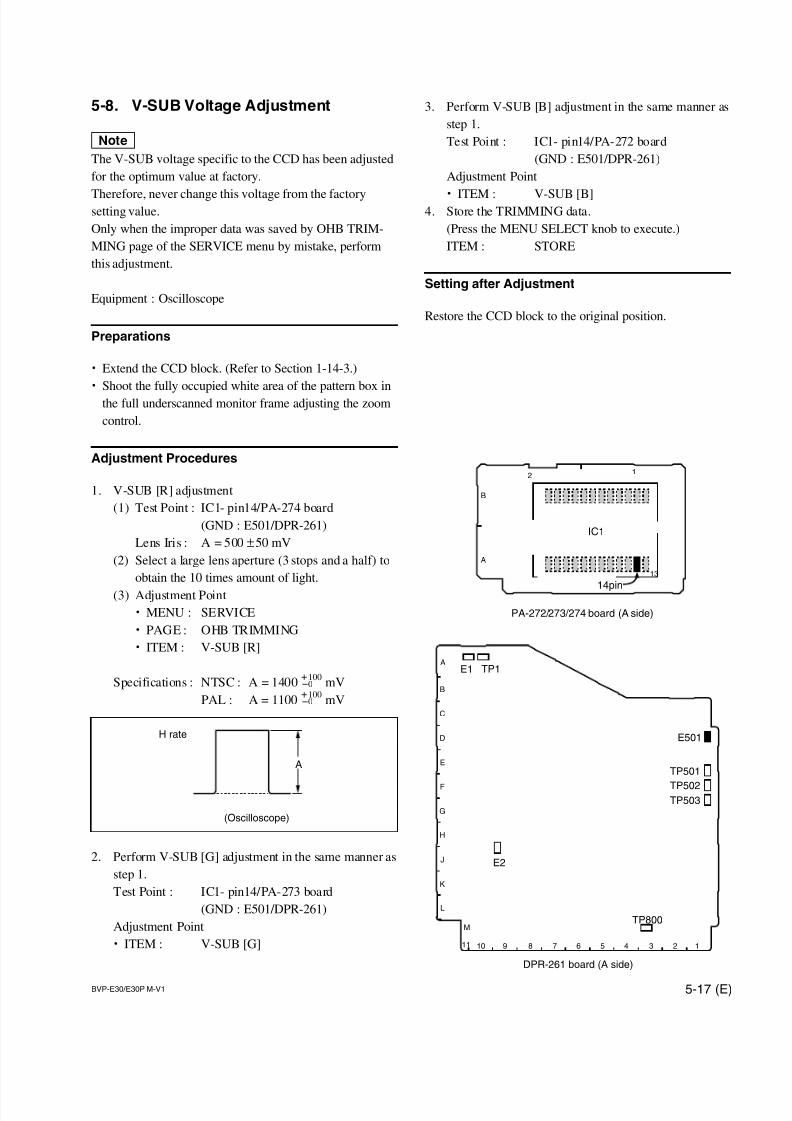
7/14/2019 Bvpe30mmi - Copy
http://slidepdf.com/reader/full/bvpe30mmi-copy 131/136
BVP-E30/E30P M-V1 5-17 (E)
TP501
TP502TP503
TP1E1
11 10 9 8 7 6 5 4 3 2 1
M
L
K
J
H
G
F
E
D
C
B
A
DPR-261 board (A side)
E501
TP800
E2
5-8. V-SUB Voltage Adjustment
nThe V-SUB voltage specific to the CCD has been adjusted
for the optimum value at factory.
Therefore, never change this voltage from the factorysetting value.
Only when the improper data was saved by OHB TRIM-
MING page of the SERVICE menu by mistake, perform
this adjustment.
Equipment : Oscilloscope
Preparations
. Extend the CCD block. (Refer to Section 1-14-3.)
. Shoot the fully occupied white area of the pattern box in
the full underscanned monitor frame adjusting the zoom
control.
Adjustment Procedures
1. V-SUB [R] adjustment
(1) Test Point : IC1- pin14/PA-274 board
(GND : E501/DPR-261)
Lens Iris : A = 500 ±50 mV
(2) Select a large lens aperture (3 stops and a half) to
obtain the 10 times amount of light.
(3) Adjustment Point
. MENU : SERVICE
. PAGE : OHB TRIMMING
. ITEM : V-SUB [R]
Specifications : NTSC : A = 1400+100
mV_0
PAL : A = 1100+100
mV_0
2. Perform V-SUB [G] adjustment in the same manner as
step 1.
Test Point : IC1- pin14/PA-273 board
(GND : E501/DPR-261)
Adjustment Point
. ITEM : V-SUB [G]
3. Perform V-SUB [B] adjustment in the same manner as
step 1.
Test Point : IC1- pin14/PA-272 board
(GND : E501/DPR-261)
Adjustment Point
. ITEM : V-SUB [B]4. Store the TRIMMING data.
(Press the MENU SELECT knob to execute.)
ITEM : STORE
Setting after Adjustment
Restore the CCD block to the original position.
A
H rate
(Oscilloscope)
IC1
2
14pin
13
1
B
A
PA-272/273/274 board (A side)
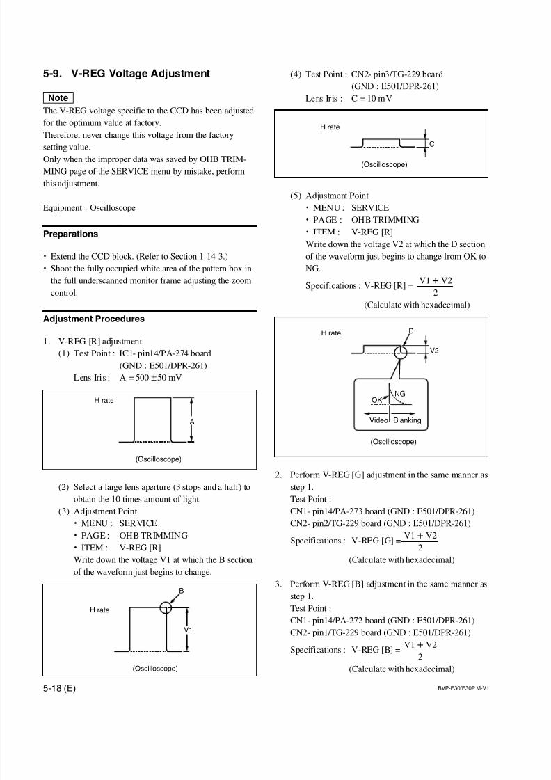
7/14/2019 Bvpe30mmi - Copy
http://slidepdf.com/reader/full/bvpe30mmi-copy 132/136
5-18 (E) BVP-E30/E30P M-V1
(4) Test Point : CN2- pin3/TG-229 board
(GND : E501/DPR-261)
Lens Iris : C = 10 mV
(5) Adjustment Point
. MENU : SERVICE
. PAGE : OHB TRIMMING
. ITEM : V-REG [R]
Write down the voltage V2 at which the D section
of the waveform just begins to change from OK to
NG.
Specifications : V-REG [R] =V1 + V2
2
(Calculate with hexadecimal)
2. Perform V-REG [G] adjustment in the same manner as
step 1.
Test Point :
CN1- pin14/PA-273 board (GND : E501/DPR-261)
CN2- pin2/TG-229 board (GND : E501/DPR-261)
Specifications : V-REG [G] =V1 + V2
2(Calculate with hexadecimal)
3. Perform V-REG [B] adjustment in the same manner as
step 1.
Test Point :
CN1- pin14/PA-272 board (GND : E501/DPR-261)
CN2- pin1/TG-229 board (GND : E501/DPR-261)
Specifications : V-REG [B] =V1 + V2
2
(Calculate with hexadecimal)
5-9. V-REG Voltage Adjustment
nThe V-REG voltage specific to the CCD has been adjusted
for the optimum value at factory.
Therefore, never change this voltage from the factorysetting value.
Only when the improper data was saved by OHB TRIM-
MING page of the SERVICE menu by mistake, perform
this adjustment.
Equipment : Oscilloscope
Preparations
. Extend the CCD block. (Refer to Section 1-14-3.)
. Shoot the fully occupied white area of the pattern box in
the full underscanned monitor frame adjusting the zoom
control.
Adjustment Procedures
1. V-REG [R] adjustment
(1) Test Point : IC1- pin14/PA-274 board
(GND : E501/DPR-261)
Lens Iris : A = 500 ±50 mV
(2) Select a large lens aperture (3 stops and a half) to
obtain the 10 times amount of light.
(3) Adjustment Point
. MENU : SERVICE
. PAGE : OHB TRIMMING
. ITEM : V-REG [R]Write down the voltage V1 at which the B section
of the waveform just begins to change.
A
(Oscilloscope)
H rate
V1
B
H rate
(Oscilloscope)
H rate
(Oscilloscope)
V2
OKNG
BlankingVideo
D
C
H rate
(Oscilloscope)
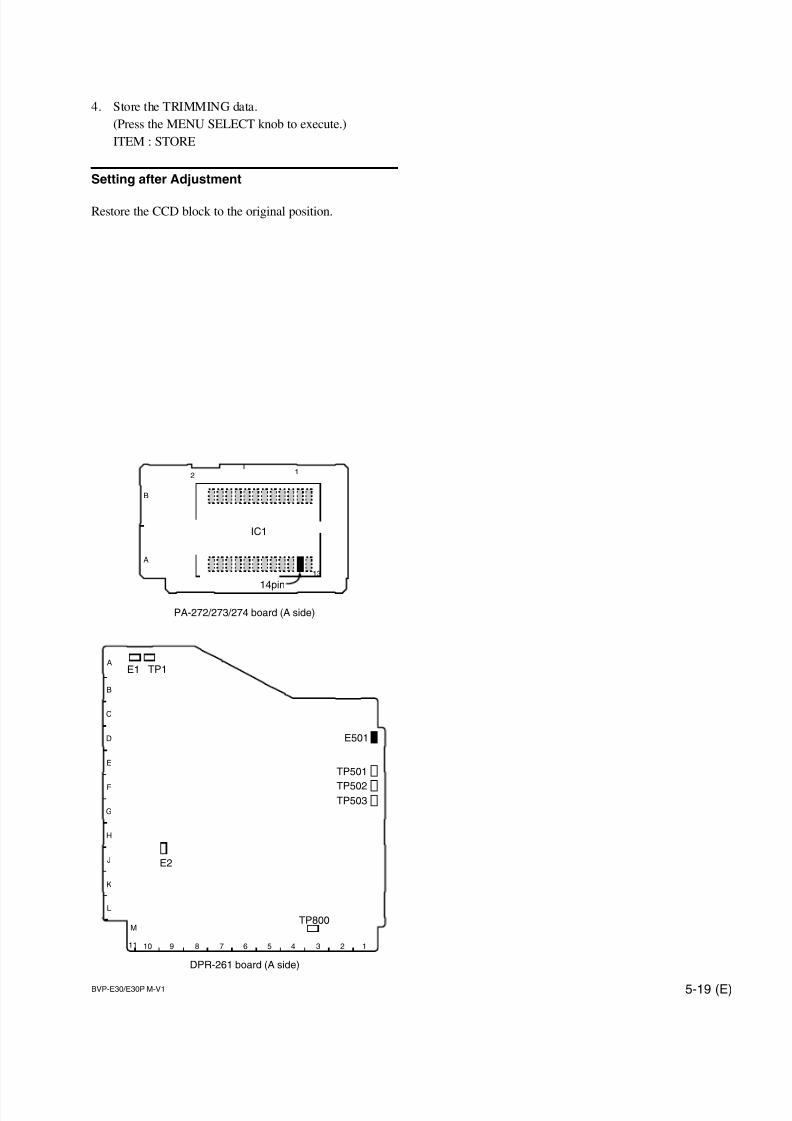
7/14/2019 Bvpe30mmi - Copy
http://slidepdf.com/reader/full/bvpe30mmi-copy 133/136
BVP-E30/E30P M-V1 5-19 (E)
TP501
TP502TP503
TP1E1
11 10 9 8 7 6 5 4 3 2 1
M
L
K
J
H
G
F
E
D
C
B
A
DPR-261 board (A side)
E501
TP800
E2
IC1
2
14pin
13
1
B
A
PA-272/273/274 board (A side)
4. Store the TRIMMING data.
(Press the MENU SELECT knob to execute.)
ITEM : STORE
Setting after Adjustment
Restore the CCD block to the original position.

7/14/2019 Bvpe30mmi - Copy
http://slidepdf.com/reader/full/bvpe30mmi-copy 134/136

7/14/2019 Bvpe30mmi - Copy
http://slidepdf.com/reader/full/bvpe30mmi-copy 135/136

7/14/2019 Bvpe30mmi - Copy
http://slidepdf.com/reader/full/bvpe30mmi-copy 136/136