Embed Size (px)
Citation preview
BV - BIG VOLUME BOOSTER INSTRUCTION MANUAL 2071
____________________________________________________________________________________ STI S.r.l. – Via Dei Caravaggi 15, 24040 Levate (BG) – ITALY www.imi-critical.com
Manual 2071, rev. 05 10/2014 – BV
i
STI S.r.l has taken every care in collecting and verifying the documentation contained in this Instruction
Manual. The information herein contained are reserved property of STI S.r.l.
____________________________________________________________________________________ STI S.r.l. – Via Dei Caravaggi 15, 24040 Levate (BG) – ITALY www.imi-critical.com
Manual 2071, rev. 05 10/2014 – BV
ii
INDEX
1 GENERAL INFORMATION .................................................................................................................. 1
1.1 GENERAL WARNINGS ........................................................................................................................ 1 1.2 GENERALITIES .................................................................................................................................. 1 1.3 MANUFACTURER ............................................................................................................................... 1 1.4 TERMS AND CONDITIONS ................................................................................................................... 1 1.5 MANUFACTURER‟S LIABILITY ............................................................................................................. 1 1.6 APPLICABLE STANDARDS AND DIRECTIVES ........................................................................................ 2 1.7 SYMBOLOGY USED ........................................................................................................................... 2
2 DEVICE DESCRIPTION ....................................................................................................................... 3
3 TECHNICAL DATA ............................................................................................................................... 4
4 LABEL ................................................................................................................................................... 4
5 INSTALLATION .................................................................................................................................... 5
5.1 TRANSPORT ..................................................................................................................................... 5 5.2 RECEPTION ...................................................................................................................................... 5 5.3 STORAGE ......................................................................................................................................... 5 5.4 REQUIREMENTS OF STABILITY ........................................................................................................... 5 5.5 DOCUMENTS AND DIMENSIONAL DRAWINGS ........................................................................................ 5 5.6 INSTALLATION ................................................................................................................................... 6 5.7 DISASSEMBLING ............................................................................................................................... 7
6 OPERATION AND USE ........................................................................................................................ 8
6.1 OPERATION DESCRIPTION ................................................................................................................. 8 6.2 INTENDED USE ................................................................................................................................ 15 6.3 REASONABLY FORESEEABLE MISUSE ............................................................................................... 15 6.4 OPERATING LIMITS .......................................................................................................................... 15 6.5 RESIDUAL RISKS ............................................................................................................................ 15
7 INSTRUCTIONS FOR THE OPERATOR ........................................................................................... 16
8 MAINTENANCE .................................................................................................................................. 17
8.1 PERIODIC INSPECTIONS .................................................................................................................. 17 8.2 SPECIAL MAINTENANCE ................................................................................................................... 17 8.3 REPAIRS ........................................................................................................................................ 17 8.4 REASSEMBLING .............................................................................................................................. 17 8.5 MECHANISM LUBRICATION............................................................................................................... 17
9 PARTS LIST GENERAL ASSEMBLY ................................................................................................ 18
9.1 BV ASSEMBLY ................................................................................................................................ 18
10 TROUBLESHOOTING .................................................................................................................... 19
11 SPARE PARTS ............................................................................................................................... 19
12 DECOMMISSIONING ...................................................................................................................... 20

____________________________________________________________________________________ STI S.r.l. – Via Dei Caravaggi 15, 24040 Levate (BG) – ITALY www.imi-critical.com
Manual 2071, rev. 05 10/2014 – BV
iii
____________________________________________________________________________________ STI S.r.l. – Via Dei Caravaggi 15, 24040 Levate (BG) – ITALY www.imi-critical.com
Manual 2071, rev. 05 10/2014 – BV - 1 -
1 GENERAL INFORMATION
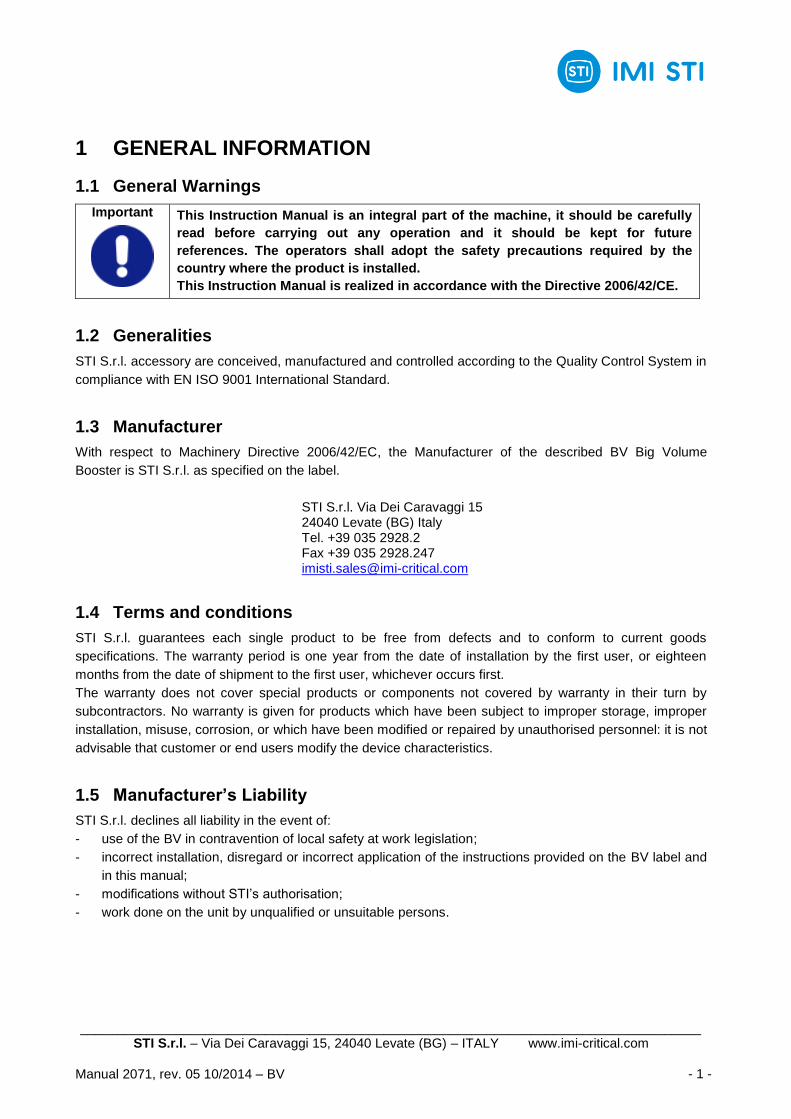
1.1 General Warnings
Important This Instruction Manual is an integral part of the machine, it should be carefully
read before carrying out any operation and it should be kept for future
references. The operators shall adopt the safety precautions required by the
country where the product is installed.
This Instruction Manual is realized in accordance with the Directive 2006/42/CE.
1.2 Generalities
STI S.r.l. accessory are conceived, manufactured and controlled according to the Quality Control System in
compliance with EN ISO 9001 International Standard.
1.3 Manufacturer
With respect to Machinery Directive 2006/42/EC, the Manufacturer of the described BV Big Volume
Booster is STI S.r.l. as specified on the label.
STI S.r.l. Via Dei Caravaggi 15 24040 Levate (BG) Italy Tel. +39 035 2928.2 Fax +39 035 2928.247 [email protected]
1.4 Terms and conditions
STI S.r.l. guarantees each single product to be free from defects and to conform to current goods
specifications. The warranty period is one year from the date of installation by the first user, or eighteen
months from the date of shipment to the first user, whichever occurs first.
The warranty does not cover special products or components not covered by warranty in their turn by
subcontractors. No warranty is given for products which have been subject to improper storage, improper
installation, misuse, corrosion, or which have been modified or repaired by unauthorised personnel: it is not
advisable that customer or end users modify the device characteristics.
1.5 Manufacturer’s Liability
STI S.r.l. declines all liability in the event of:
- use of the BV in contravention of local safety at work legislation;
- incorrect installation, disregard or incorrect application of the instructions provided on the BV label and
in this manual;
- modifications without STI‟s authorisation;
- work done on the unit by unqualified or unsuitable persons.
____________________________________________________________________________________ STI S.r.l. – Via Dei Caravaggi 15, 24040 Levate (BG) – ITALY www.imi-critical.com
Manual 2071, rev. 05 10/2014 – BV - 2 -
1.6 Applicable Standards and Directives
- EN ISO 12100:2010 Safety of machinery - General principles for design;
- IEC 61508:2010 Functional Safety of Electrical/Electronic/Programmable Electronic Safety-
related Systems;
- 2006/42/EC Machinery Directive;
- 97/23/EC Pressure Equipments Directive (PED);
- 94/9/CE Equipments used in potentially explosive atmospheres (ATEX).
1.7 Symbology Used
1.7.1 Signs of warning
Be careful where these symbols are shown, they indicate a potentially hazardous situation and they warn that if the steps are not properly performed, MAY RESULT CAUSING serious injury, death or long-term risks to the health of exposed persons.
1.7.2 Sings of obligation
General
obligation (with the possible
supplementary signboard)
Must wear protective clothing.
Obligation to wear
protective footwear.
Is required to wear a helmet.
Is required to protect the
eyes.
Obligation to protect your
hearing.
GENERAL DANGER DANGER POWER SUPPLY CRUSHING HAZARD
____________________________________________________________________________________ STI S.r.l. – Via Dei Caravaggi 15, 24040 Levate (BG) – ITALY www.imi-critical.com
Manual 2071, rev. 05 10/2014 – BV - 3 -
2 DEVICE DESCRIPTION
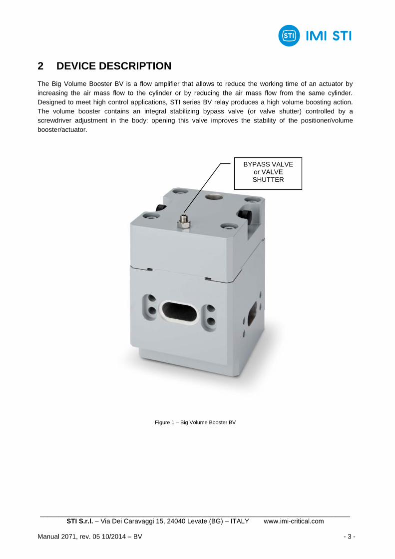
The Big Volume Booster BV is a flow amplifier that allows to reduce the working time of an actuator by
increasing the air mass flow to the cylinder or by reducing the air mass flow from the same cylinder.
Designed to meet high control applications, STI series BV relay produces a high volume boosting action.
The volume booster contains an integral stabilizing bypass valve (or valve shutter) controlled by a
screwdriver adjustment in the body: opening this valve improves the stability of the positioner/volume
booster/actuator.
Figure 1 – Big Volume Booster BV
BYPASS VALVE or VALVE SHUTTER
____________________________________________________________________________________ STI S.r.l. – Via Dei Caravaggi 15, 24040 Levate (BG) – ITALY www.imi-critical.com
Manual 2071, rev. 05 10/2014 – BV - 4 -
3 TECHNICAL DATA
Technical features
Model Type A Type B
Housing material Aluminum Stainless steel
Size 1” 1”
Feeding connections Plug-in - 1”NPTF Plug-in - 1”NPTF
Outlet connections Plug-in Plug-in
Signal connection ½” NPTF ½” NPTF
Operating temperature range -60/+100 °C -60/+100 °C
Design pressure 10 bar 10 bar
Operating pressure range See label See label
Expected lifetime 20 years 20 years
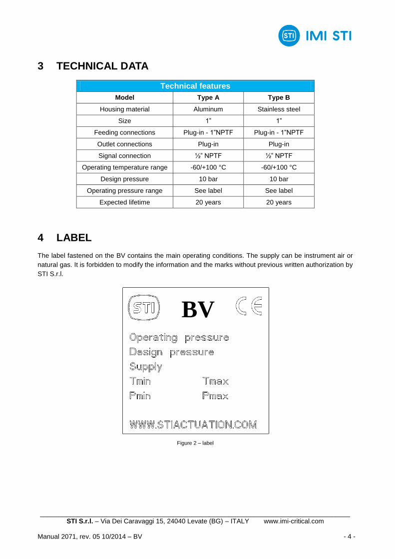
4 LABEL
The label fastened on the BV contains the main operating conditions. The supply can be instrument air or
natural gas. It is forbidden to modify the information and the marks without previous written authorization by
STI S.r.l.
Figure 2 – label
BV
____________________________________________________________________________________ STI S.r.l. – Via Dei Caravaggi 15, 24040 Levate (BG) – ITALY www.imi-critical.com
Manual 2071, rev. 05 10/2014 – BV - 5 -
5 INSTALLATION
Important
Not performing the following procedures will invalidate the product guarantee.
5.1 Transport
Important
The lifting and handling should be made by qualified staff and in compliance with
the laws and provisions in force.
5.2 Reception
- Check that the model correspond with that of order confirmation.
- Check that the BV was not damaged during transportation: if necessary renovate the painting according
to the specification reported on the order confirmation.
5.3 Storage
Big Volume Boosters leave the factory in perfect condition. Performances of each unit are guaranteed by
tests and data reported on a specific Test Report. In order to maintain these characteristics until the BV is
installed on site, proper attention must be observed for preservation during the storage period.
If the BV needs storage, before installation follow these steps:
- place it on a wood surface pallet or on metallic support, so that they are not in direct contact with the
ground, or packed with appropriate covering;
- make sure that plastic plugs are present on the pneumatic connections (if present).
If the storage is long-term or outdoor:
- keep the BV protected from direct weather conditions;
- replace plastic plugs of pneumatic connections (if any) with metal plugs that guarantee perfect
tightness.
5.4 Requirements of Stability
Concerning the requirement of stability during installation and disassembling it„s possible to refer to the
next chapters 5.6 and 5.7.
5.5 Documents and dimensional drawings
Pneumatic diagrams, wiring diagrams and dimensional drawings are furnished with document
accompanying the actuator.
____________________________________________________________________________________ STI S.r.l. – Via Dei Caravaggi 15, 24040 Levate (BG) – ITALY www.imi-critical.com
Manual 2071, rev. 05 10/2014 – BV - 6 -
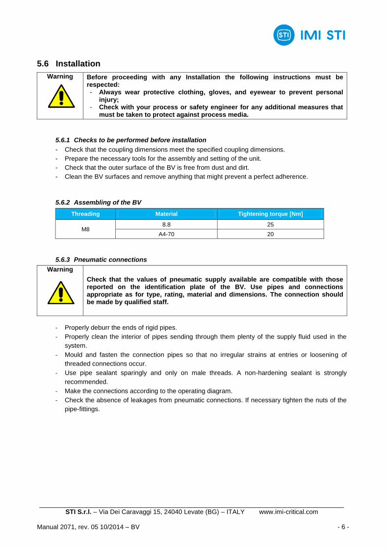
5.6 Installation
Warning
Before proceeding with any Installation the following instructions must be respected: - Always wear protective clothing, gloves, and eyewear to prevent personal
injury; - Check with your process or safety engineer for any additional measures that
must be taken to protect against process media.
5.6.1 Checks to be performed before installation
- Check that the coupling dimensions meet the specified coupling dimensions.
- Prepare the necessary tools for the assembly and setting of the unit.
- Check that the outer surface of the BV is free from dust and dirt.
- Clean the BV surfaces and remove anything that might prevent a perfect adherence.
5.6.2 Assembling of the BV
Threading Material Tightening torque [Nm]
M8 8.8 25
A4-70 20
5.6.3 Pneumatic connections
Warning
Check that the values of pneumatic supply available are compatible with those reported on the identification plate of the BV. Use pipes and connections appropriate as for type, rating, material and dimensions. The connection should be made by qualified staff.
- Properly deburr the ends of rigid pipes.
- Properly clean the interior of pipes sending through them plenty of the supply fluid used in the
system.
- Mould and fasten the connection pipes so that no irregular strains at entries or loosening of
threaded connections occur.
- Use pipe sealant sparingly and only on male threads. A non-hardening sealant is strongly
recommended.
- Make the connections according to the operating diagram.
- Check the absence of leakages from pneumatic connections. If necessary tighten the nuts of the
pipe-fittings.
____________________________________________________________________________________ STI S.r.l. – Via Dei Caravaggi 15, 24040 Levate (BG) – ITALY www.imi-critical.com
Manual 2071, rev. 05 10/2014 – BV - 7 -
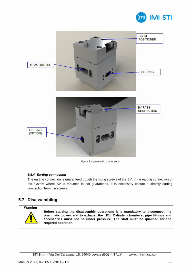
Figure 3 – pneumatic connections
5.6.4 Earting connection
The earting connection is guaranteed trough the fixing screws of the BV. If the earting connection of
the system where BV is mounted is not guaranteed, it is necessary ensure a directly earting
connection from the screws.
5.7 Disassembling
Warning
Before starting the disassembly operations it is mandatory to disconnect the pneumatic power and to exhaust the BV. Cylinder chambers, pipe fittings and accessories must not be under pressure. The staff must be qualified for the required operation.
____________________________________________________________________________________ STI S.r.l. – Via Dei Caravaggi 15, 24040 Levate (BG) – ITALY www.imi-critical.com
Manual 2071, rev. 05 10/2014 – BV - 8 -
6 OPERATION AND USE
6.1 Operation description
Big Volume Booster BV has 2 main setups: charge (figure 4, 5, 6) and discharge (figure 7, 8, 9). The valve
shutter may create a pressure drop depending on its adjustment and the working fluid flow rate.
In the charge setup the working fluid from the pilot passes through the valve shutter:
a) if the flow rate is lower than a threshold value depending on valve shutter adjustment, the valve shutter
throttling can‟t generate a pressure drop between the two side of the piston and the working fluid goes
to the actuator chamber. This case is called “stand-by mode” (figure 4);
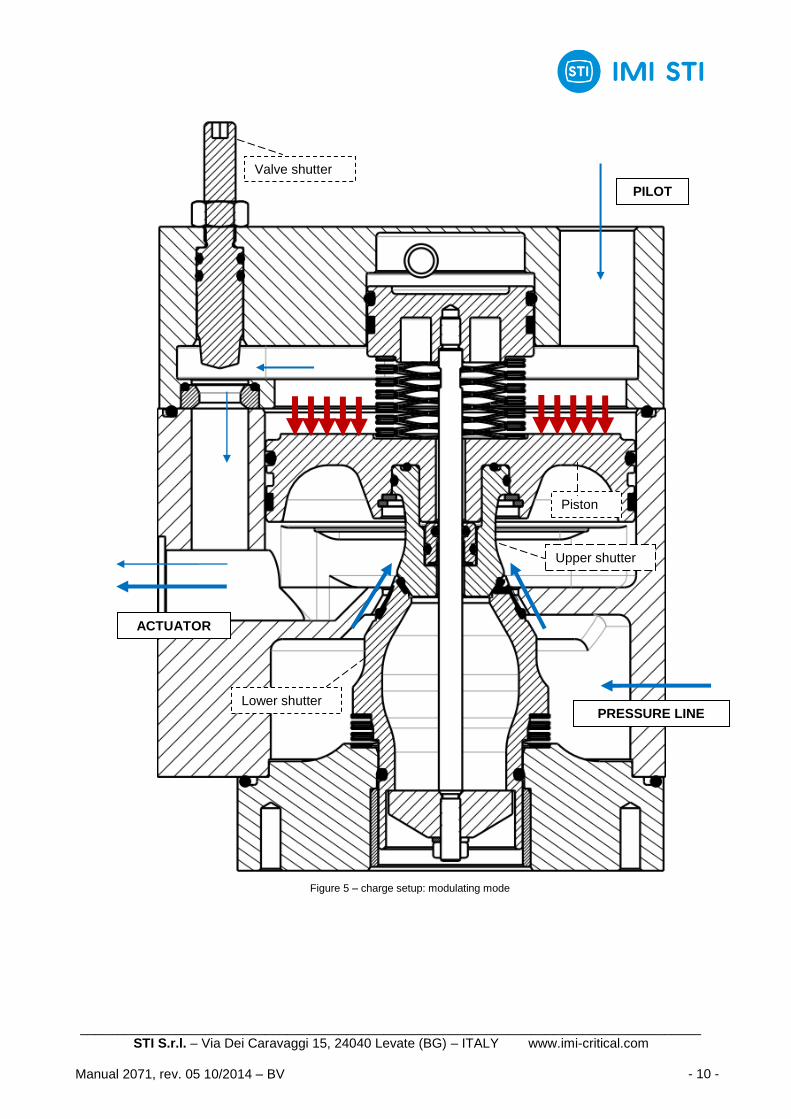
b) if the flow rate is greater than a threshold value depending on valve shutter adjustment, the valve
shutter throttling generates a pressure drop between the two side of the piston and the working fluid
pushes down the piston and the lower shutter, allowing the connection between the BV supply
chamber and the actuator chamber. This case is called “modulating mode” (figure 5);
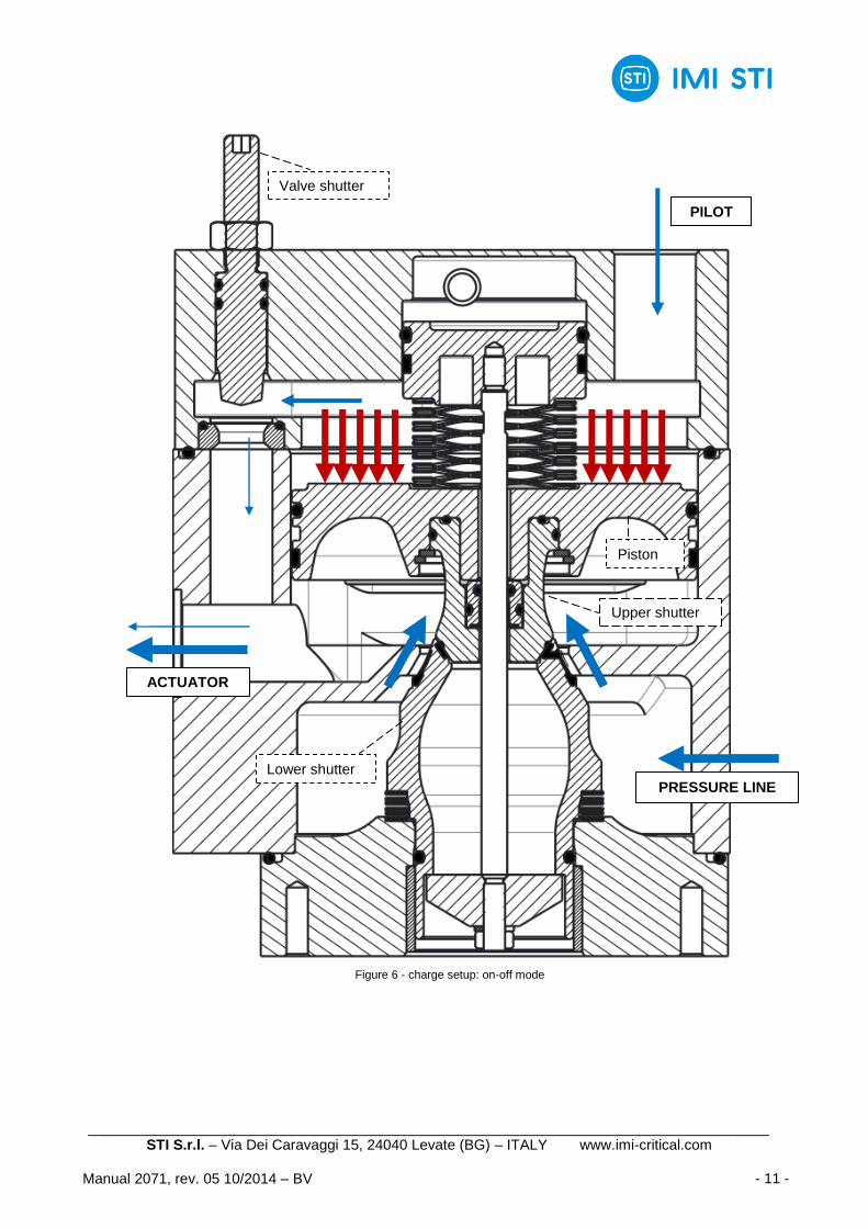
c) if the flow rate is much greater than a threshold value depending on valve shutter adjustment, the
valve shutter throttling generates a pressure drop between the two side of the piston and the working
fluid pushes down the piston and the lower shutter, allowing the connection between the BV supply
chamber and the actuator chamber. In this case the lower shutter generates the greatest flow section
available because the piston reaches its lower stroke limit. This case is called “on-off mode” (figure 6).
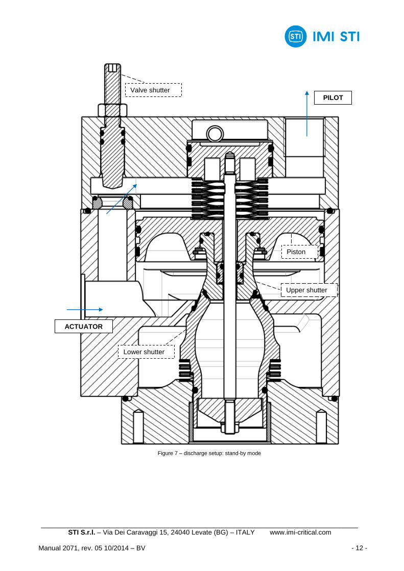
In the discharge setup the working fluid from the actuator passes through the valve shutter:
a) if the flow rate is lower than a threshold value depending on valve shutter adjustment, the valve shutter
throttling can‟t generate a pressure drop between the two side of the piston and the working fluid goes
to the pilot. This case is called “stand-by mode” (figure 7);
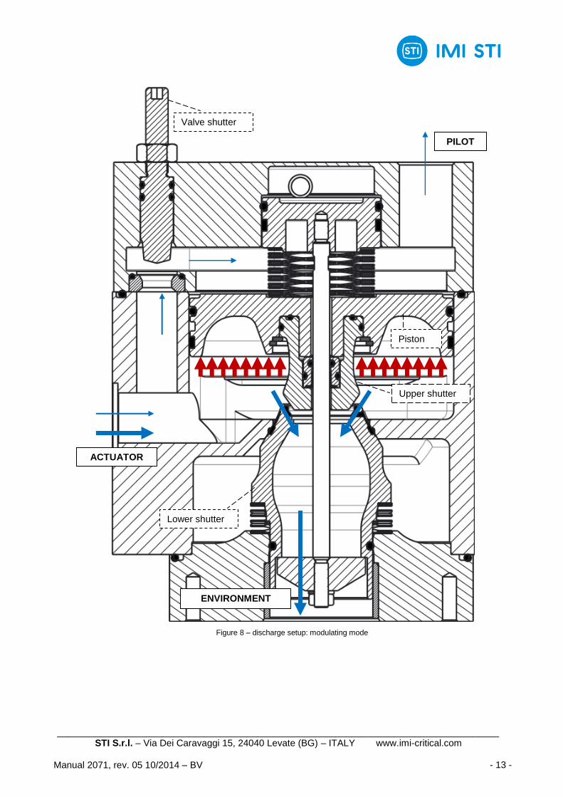
b) if the flow rate is greater than a threshold value depending on valve shutter adjustment, the valve
shutter throttling generates a pressure drop between the two side of the piston and the working fluid
pushes up the piston, allowing the connection between the actuator chamber and the exhaust
chamber. This case is called “modulating mode” (figure 8);
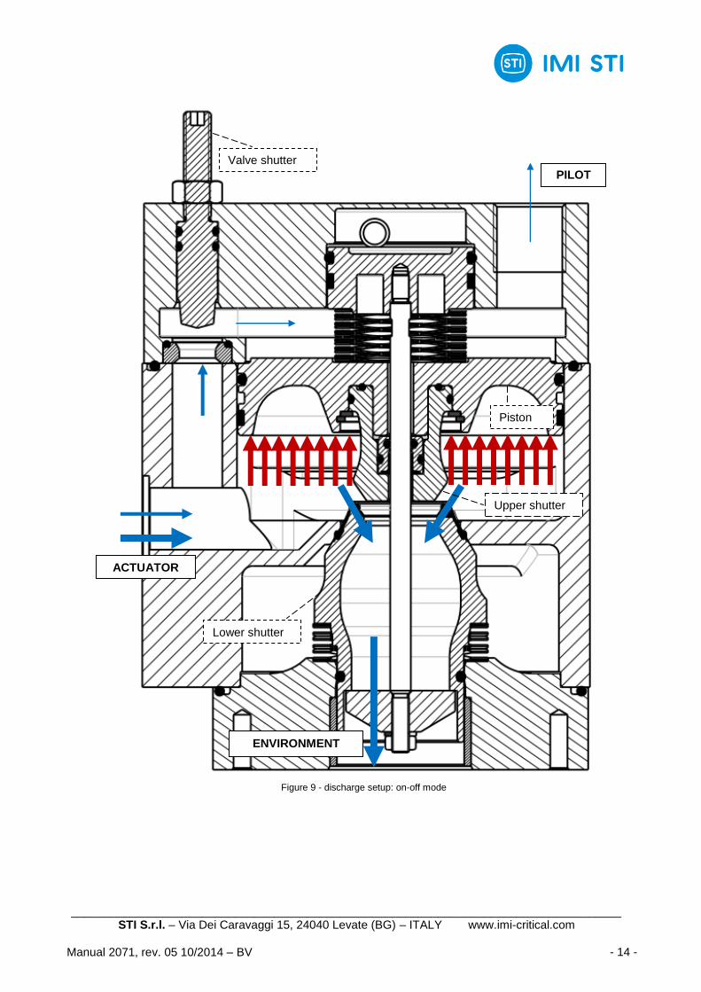
c) if the flow rate is much greater than a threshold value depending on valve shutter adjustment, the
valve shutter throttling generates a pressure drop between the two side of the piston and the working
fluid pushes up the piston, allowing the connection between the actuator chamber and the exhaust
chamber. In this case the upper shutter generates the greatest flow section available because the
piston reaches its upper stroke limit. This case is called “on-off mode” (figure 9).

____________________________________________________________________________________ STI S.r.l. – Via Dei Caravaggi 15, 24040 Levate (BG) – ITALY www.imi-critical.com
Manual 2071, rev. 05 10/2014 – BV - 9 -
Figure 4 – charge setup: stand-by mode
PILOT
ACTUATOR
Valve shutter
Upper shutter
Piston
Lower shutter
____________________________________________________________________________________ STI S.r.l. – Via Dei Caravaggi 15, 24040 Levate (BG) – ITALY www.imi-critical.com
Manual 2071, rev. 05 10/2014 – BV - 10 -
Figure 5 – charge setup: modulating mode
PILOT
ACTUATOR
PRESSURE LINE
Valve shutter
Upper shutter
Piston
Lower shutter
____________________________________________________________________________________ STI S.r.l. – Via Dei Caravaggi 15, 24040 Levate (BG) – ITALY www.imi-critical.com
Manual 2071, rev. 05 10/2014 – BV - 11 -
Figure 6 - charge setup: on-off mode
PILOT
ACTUATOR
PRESSURE LINE
Valve shutter
Upper shutter
Piston
Lower shutter
____________________________________________________________________________________ STI S.r.l. – Via Dei Caravaggi 15, 24040 Levate (BG) – ITALY www.imi-critical.com
Manual 2071, rev. 05 10/2014 – BV - 12 -
Figure 7 – discharge setup: stand-by mode
ACTUATOR
PILOT Valve shutter
Upper shutter
Piston
Lower shutter
____________________________________________________________________________________ STI S.r.l. – Via Dei Caravaggi 15, 24040 Levate (BG) – ITALY www.imi-critical.com
Manual 2071, rev. 05 10/2014 – BV - 13 -
Figure 8 – discharge setup: modulating mode
ACTUATOR
PILOT
ENVIRONMENT
Valve shutter
Upper shutter
Piston
Lower shutter
____________________________________________________________________________________ STI S.r.l. – Via Dei Caravaggi 15, 24040 Levate (BG) – ITALY www.imi-critical.com
Manual 2071, rev. 05 10/2014 – BV - 14 -
Figure 9 - discharge setup: on-off mode
ACTUATOR
PILOT
ENVIRONMENT
Valve shutter
Upper shutter
Piston
Lower shutter
____________________________________________________________________________________ STI S.r.l. – Via Dei Caravaggi 15, 24040 Levate (BG) – ITALY www.imi-critical.com
Manual 2071, rev. 05 10/2014 – BV - 15 -
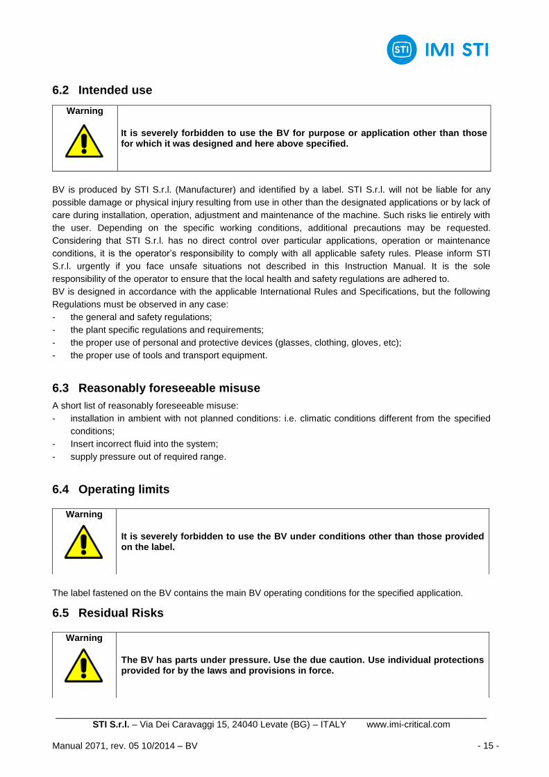
6.2 Intended use
BV is produced by STI S.r.l. (Manufacturer) and identified by a label. STI S.r.l. will not be liable for any
possible damage or physical injury resulting from use in other than the designated applications or by lack of
care during installation, operation, adjustment and maintenance of the machine. Such risks lie entirely with
the user. Depending on the specific working conditions, additional precautions may be requested.
Considering that STI S.r.l. has no direct control over particular applications, operation or maintenance
conditions, it is the operator‟s responsibility to comply with all applicable safety rules. Please inform STI
S.r.l. urgently if you face unsafe situations not described in this Instruction Manual. It is the sole
responsibility of the operator to ensure that the local health and safety regulations are adhered to.
BV is designed in accordance with the applicable International Rules and Specifications, but the following
Regulations must be observed in any case:
- the general and safety regulations;
- the plant specific regulations and requirements;
- the proper use of personal and protective devices (glasses, clothing, gloves, etc);
- the proper use of tools and transport equipment.
6.3 Reasonably foreseeable misuse
A short list of reasonably foreseeable misuse:
- installation in ambient with not planned conditions: i.e. climatic conditions different from the specified
conditions;
- Insert incorrect fluid into the system;
- supply pressure out of required range.
6.4 Operating limits
The label fastened on the BV contains the main BV operating conditions for the specified application.
6.5 Residual Risks
Warning
It is severely forbidden to use the BV for purpose or application other than those for which it was designed and here above specified.
Warning
It is severely forbidden to use the BV under conditions other than those provided on the label.
Warning
The BV has parts under pressure. Use the due caution. Use individual protections provided for by the laws and provisions in force.
____________________________________________________________________________________ STI S.r.l. – Via Dei Caravaggi 15, 24040 Levate (BG) – ITALY www.imi-critical.com
Manual 2071, rev. 05 10/2014 – BV - 16 -
- Risk due to movements of loads during load displacements and assemblage.
- Crushing during assemblage servicing.
- Extreme metal temperature at high (over than 80°C) or very low values as consequence of ambient
temperature as to be considered as a risk of person injury in case of contact.
- Emissions of hazardous substances where natural gas is used as motive energy.
7 Instructions for the operator
During the start-up of the BV, proceed as follows:
- check that the pressure and quality of the air supply (filtering degree, dehydration) are as prescribed;
- check that there are not leak in the pneumatic connections. If necessary tighten the nuts of the pipe
fittings;
- remove all rust and, in accordance with the applicable painting specifications, repair paint-coat that has
been damaged during transport, storage or assembly;
- prior to operation, turn the bypass adjusting screw counter clockwise to the fully opened position. With
the actuator in operation, slowly turn the bypass screw until the booster operates in response to large
changes in the input signal, yet allows small changes to move the actuator without booster firing.
____________________________________________________________________________________ STI S.r.l. – Via Dei Caravaggi 15, 24040 Levate (BG) – ITALY www.imi-critical.com
Manual 2071, rev. 05 10/2014 – BV - 17 -
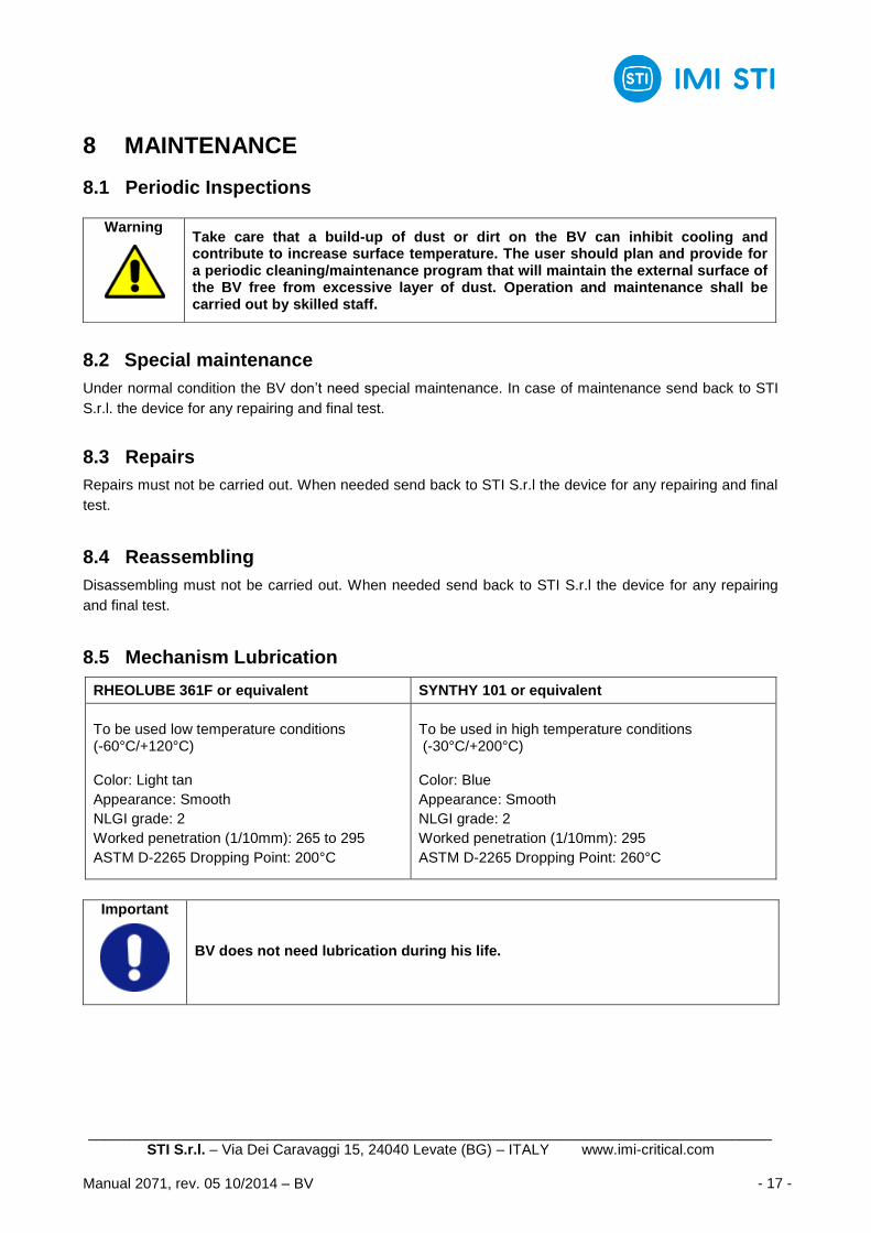
8 MAINTENANCE
8.1 Periodic Inspections
8.2 Special maintenance
Under normal condition the BV don‟t need special maintenance. In case of maintenance send back to STI
S.r.l. the device for any repairing and final test.
8.3 Repairs
Repairs must not be carried out. When needed send back to STI S.r.l the device for any repairing and final
test.
8.4 Reassembling
Disassembling must not be carried out. When needed send back to STI S.r.l the device for any repairing
and final test.
8.5 Mechanism Lubrication
RHEOLUBE 361F or equivalent SYNTHY 101 or equivalent
To be used low temperature conditions (-60°C/+120°C) Color: Light tan
Appearance: Smooth
NLGI grade: 2
Worked penetration (1/10mm): 265 to 295
ASTM D-2265 Dropping Point: 200°C
To be used in high temperature conditions (-30°C/+200°C)
Color: Blue
Appearance: Smooth
NLGI grade: 2
Worked penetration (1/10mm): 295
ASTM D-2265 Dropping Point: 260°C
Important
BV does not need lubrication during his life.
Warning Take care that a build-up of dust or dirt on the BV can inhibit cooling and contribute to increase surface temperature. The user should plan and provide for a periodic cleaning/maintenance program that will maintain the external surface of the BV free from excessive layer of dust. Operation and maintenance shall be carried out by skilled staff.
____________________________________________________________________________________ STI S.r.l. – Via Dei Caravaggi 15, 24040 Levate (BG) – ITALY www.imi-critical.com
Manual 2071, rev. 05 10/2014 – BV - 18 -
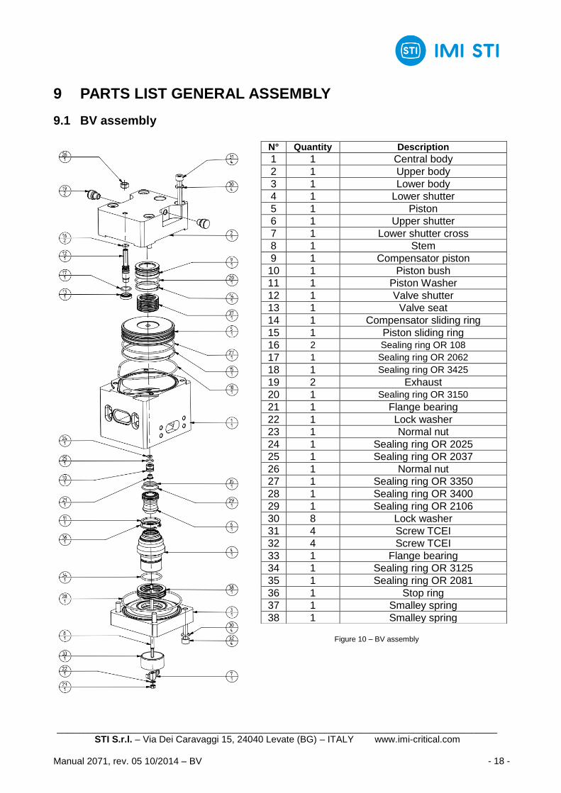
9 PARTS LIST GENERAL ASSEMBLY
9.1 BV assembly
Figure 10 – BV assembly
N° Quantity Description
1 1 Central body
2 1 Upper body
3 1 Lower body
4 1 Lower shutter
5 1 Piston
6 1 Upper shutter
7 1 Lower shutter cross
8 1 Stem
9 1 Compensator piston
10 1 Piston bush
11 1 Piston Washer
12 1 Valve shutter
13 1 Valve seat
14 1 Compensator sliding ring
15 1 Piston sliding ring
16 2 Sealing ring OR 108
17 1 Sealing ring OR 2062
18 1 Sealing ring OR 3425
19 2 Exhaust
20 1 Sealing ring OR 3150
21 1 Flange bearing
22 1 Lock washer
23 1 Normal nut
24 1 Sealing ring OR 2025
25 1 Sealing ring OR 2037
26 1 Normal nut
27 1 Sealing ring OR 3350
28 1 Sealing ring OR 3400
29 1 Sealing ring OR 2106
30 8 Lock washer
31 4 Screw TCEI
32 4 Screw TCEI
33 1 Flange bearing
34 1 Sealing ring OR 3125
35 1 Sealing ring OR 2081
36 1 Stop ring
37 1 Smalley spring
38 1 Smalley spring
____________________________________________________________________________________ STI S.r.l. – Via Dei Caravaggi 15, 24040 Levate (BG) – ITALY www.imi-critical.com
Manual 2071, rev. 05 10/2014 – BV - 19 -
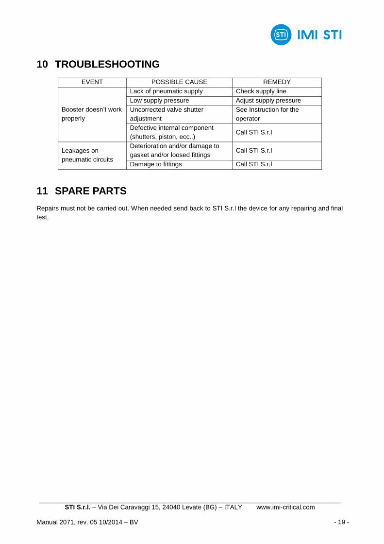
10 TROUBLESHOOTING
EVENT POSSIBLE CAUSE REMEDY
Booster doesn‟t work
properly
Lack of pneumatic supply Check supply line
Low supply pressure Adjust supply pressure
Uncorrected valve shutter
adjustment
See Instruction for the
operator
Defective internal component
(shutters, piston, ecc..) Call STI S.r.l
Leakages on
pneumatic circuits
Deterioration and/or damage to
gasket and/or loosed fittings Call STI S.r.l
Damage to fittings Call STI S.r.l
11 SPARE PARTS
Repairs must not be carried out. When needed send back to STI S.r.l the device for any repairing and final
test.
____________________________________________________________________________________ STI S.r.l. – Via Dei Caravaggi 15, 24040 Levate (BG) – ITALY www.imi-critical.com
Manual 2071, rev. 05 10/2014 – BV - 20 -
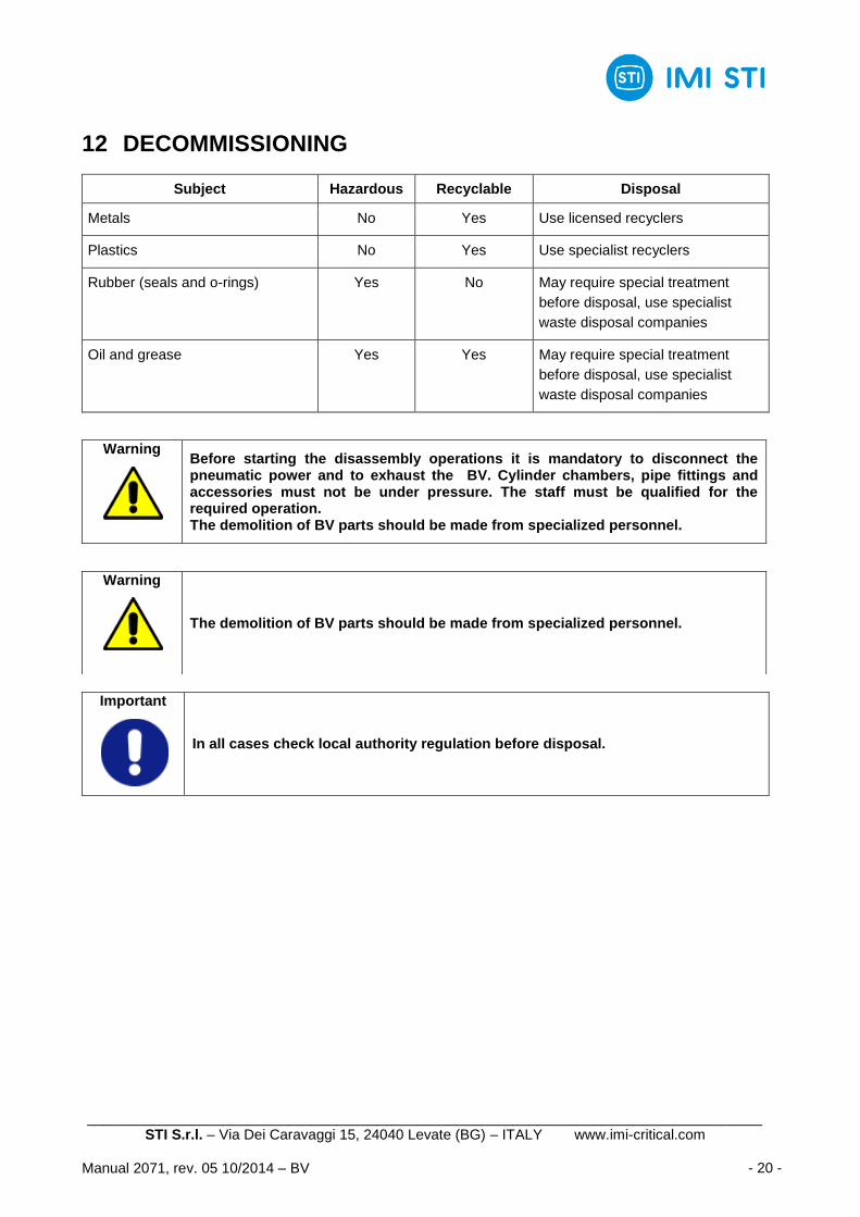
12 DECOMMISSIONING
Subject Hazardous Recyclable Disposal
Metals No Yes Use licensed recyclers
Plastics No Yes Use specialist recyclers
Rubber (seals and o-rings) Yes No May require special treatment
before disposal, use specialist
waste disposal companies
Oil and grease Yes Yes May require special treatment
before disposal, use specialist
waste disposal companies
Important
In all cases check local authority regulation before disposal.
Warning Before starting the disassembly operations it is mandatory to disconnect the pneumatic power and to exhaust the BV. Cylinder chambers, pipe fittings and accessories must not be under pressure. The staff must be qualified for the required operation. The demolition of BV parts should be made from specialized personnel.
Warning
The demolition of BV parts should be made from specialized personnel.