Embed Size (px)
Citation preview
Buttweld Fittings
Probably the simplest way to achieve this would be to bendthe pipe in the direction required, but this process will stretchand thin the outer wall whilst thickening and wrinkling the innerwall. This results in flow resistance and accelerated wallerosion.
A second method sometimes used is a mitre joint, where pipesare cut to the correct angle and welded together to achieve thedesired change. Whilst the cross-sectional area and wallthickness are maintained, a great deal of efficiency is lost dueto friction and turbulence resulting from the severe changes indirection. For example, a single-mitre bend offers about sixtimes the resistance of a swept elbow.
For these reasons swept fittings are preferred on most pipingsystems, particularly where internal pressure, flow andcorrosion are of major consideration.
TYPES AND APPLICATIONS OF BUTTWELDFITTINGS
A piping system using buttweld fittings has many inherentadvantages over other forms.
• Welding a fitting to the pipe means it is permanentlyleakproof.
• The continuous metal structure formed between pipe andfitting adds strength to the system.
• Smooth inner surface and gradual directional changesreduce pressure losses and turbulence and minimise theaction of corrosion and erosion.
• A welded system utilises a minimum of space.
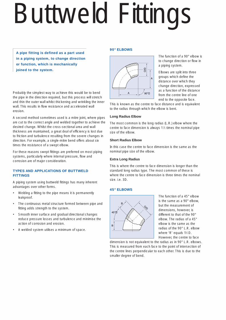
90° ELBOWS
The function of a 90° elbow is to change direction or flow in a piping system.
Elbows are split into threegroups which define thedistance over which theychange direction, expressedas a function of the distancefrom the centre line of oneend to the opposite face.
This is known as the centre to face distance and is equivalentto the radius through which the elbow is bent.
Long Radius Elbow
The most common is the long radius (L.R.) elbow where the centre to face dimension is always 11⁄2 times the nominal pipesize of the elbow.
Short Radius Elbow
In this case the centre to face dimension is the same as thenominal pipe size of the elbow.
Extra Long Radius
This is where the centre to face dimension is longer than thestandard long radius type. The most common of these iswhere the centre to face dimension is three times the nominalsize. i.e. 3D.
45° ELBOWS
The function of a 45° elbowis the same as a 90° elbow,but the measurement ofdimensions, however, isdifferent to that of the 90°elbow. The radius of a 45°elbow is the same as theradius of the 90° L.R. elbowwhere ‘R’ equals 11⁄2 D.However, the centre to face
dimension is not equivalent to the radius as in 90° L.R. elbows.This is measured from each face to the point of intersection ofthe centre lines perpendicular to each other. This is due to thesmaller degree of bend.
A
90°�A
O/D
B
B
45°�
O/D
A pipe fitting is defined as a part used
in a piping system, to change direction
or function, which is mechanically
joined to the system.
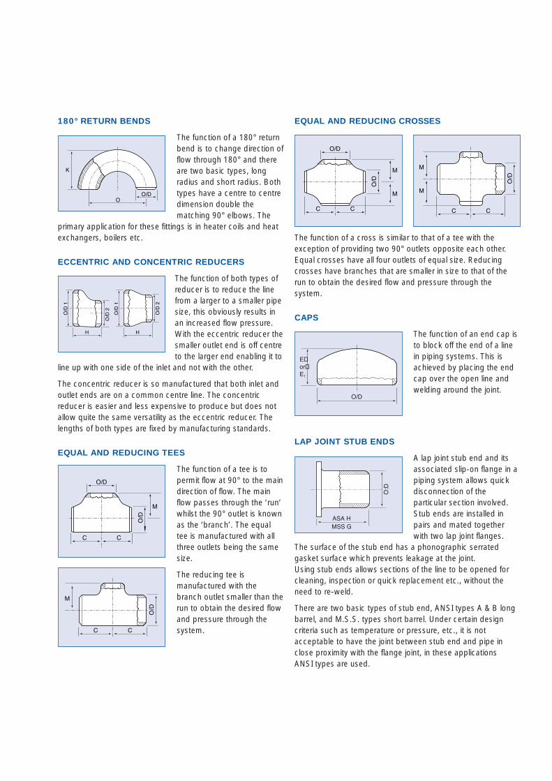
180° RETURN BENDS
The function of a 180° returnbend is to change direction offlow through 180° and thereare two basic types, longradius and short radius. Bothtypes have a centre to centredimension double thematching 90° elbows. The
primary application for these fittings is in heater coils and heatexchangers, boilers etc.
ECCENTRIC AND CONCENTRIC REDUCERS
The function of both types ofreducer is to reduce the linefrom a larger to a smaller pipesize, this obviously results inan increased flow pressure.With the eccentric reducer thesmaller outlet end is off centreto the larger end enabling it to
line up with one side of the inlet and not with the other.
The concentric reducer is so manufactured that both inlet andoutlet ends are on a common centre line. The concentricreducer is easier and less expensive to produce but does notallow quite the same versatility as the eccentric reducer. Thelengths of both types are fixed by manufacturing standards.
EQUAL AND REDUCING TEES
The function of a tee is topermit flow at 90° to the maindirection of flow. The mainflow passes through the ‘run’whilst the 90° outlet is knownas the ‘branch’. The equaltee is manufactured with allthree outlets being the samesize.
The reducing tee ismanufactured with thebranch outlet smaller than therun to obtain the desired flowand pressure through thesystem.
M
C C
O/D
M
C C
O/D
O/D
O/D
1
H
O/D
1
O/D
2
O/D
2
H
K
OO/D
EQUAL AND REDUCING CROSSES
The function of a cross is similar to that of a tee with theexception of providing two 90° outlets opposite each other.Equal crosses have all four outlets of equal size. Reducingcrosses have branches that are smaller in size to that of therun to obtain the desired flow and pressure through thesystem.
CAPS
The function of an end cap isto block off the end of a linein piping systems. This isachieved by placing the endcap over the open line andwelding around the joint.
LAP JOINT STUB ENDS
A lap joint stub end and itsassociated slip-on flange in apiping system allows quickdisconnection of theparticular section involved.Stub ends are installed inpairs and mated togetherwith two lap joint flanges.
The surface of the stub end has a phonographic serratedgasket surface which prevents leakage at the joint. Using stub ends allows sections of the line to be opened forcleaning, inspection or quick replacement etc., without theneed to re-weld.
There are two basic types of stub end, ANSI types A & B longbarrel, and M.S.S. types short barrel. Under certain designcriteria such as temperature or pressure, etc., it is notacceptable to have the joint between stub end and pipe inclose proximity with the flange joint, in these applicationsANSI types are used.
M
M
C C
O/D
M
M
C C
O/D
O/D
O/D
E�or�E1
ASA HMSS G
O:D