Embed Size (px)
Citation preview
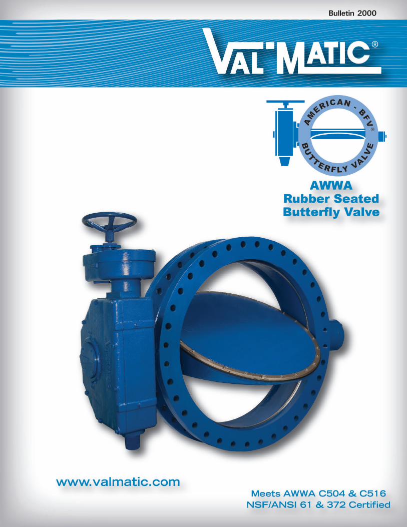
Bulletin 2000
2
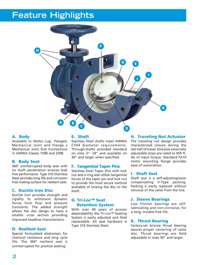
Feature Highlights
A. BodyAvailable in Wafer, Lug, Flanged,Mechanical Joint and Flange xMechanical Joint End Connectionsin AWWA Classes 150B and 250B.
B. Body Seat360° uninterrupted body seat withno shaft penetration ensures leakfree performance. Type 316 StainlessSteel provides long life and corrosionfree mating surface for resilient seat.
C. Ductile Iron DiscDuctile Iron provides strength andrigidity to withstand dynamicforces from flow and pressuretransients. The added strengthallows the disc design to have asmaller cross section providingimproved headloss characteristics.
D. Resilient SeatSpecial formulated elastomers forchemical resistance and long cyclelife. The 360° resilient seat isuninterrupted for positive seating.
E. ShaftStainless Steel shafts meet AWWAC504 diameter requirements.Through-shafts provided standardon sizes 3”- 24” and available on30” and larger when specified.
F. Tangential Taper PinsStainless Steel Taper Pins with locknut and o-ring seal utilize tangentialforces of the taper pin and lock nutto provide the most secure methodavailable of locking the disc to theshaft.
G. Tri-Loc™ SeatRetention System
With over 40 years of provendependability the Tri-Loc™ SeatingSystem is easily adjusted and fieldreplaceable. All seat hardware isType 316 Stainless Steel.
H. Traveling Nut ActuatorThe traveling nut design providescharacterized closure during thelast half of travel. Exclusive externallyadjustable stops are rated to 450 ft-lbs of input torque. Standard FA10motor mounting flange providesease of automation.
I. Shaft SealShaft seal is a self-adjusting/wearcompensating V-Type packing.Packing is easily replaced withoutremoval of the valve from the line.
J. Sleeve BearingsLow friction bearings are self-lubricating and non-corrosive, fora long, trouble-free life.
K. Thrust BearingFactory-set bronze thrust bearingassures proper centering of valvedisc. Thrust bearings are fieldadjustable in sizes 30” and larger.
A BC
D
E
F
G
JI
K
H
Proven DesignThe American-BFV® is designed, manufactured, andtested to meet all AWWA C504 and C516 requirementsincluding performance tests, leakage tests, andhydrostatic testing. Proof of Design Testing wassuccessfully completed and third-party flow testingwas performed at the Utah State Hydraulics Lab, oneof the premier testing labs in the world. Withthousands of field installations throughout the world,the American-BFV® design has proven dependablesince 1971. The valves are certified for use in drinkingwater in accordance with NSF/ANSI 61 and areNSF/ANSI 372 Certified Lead-Free.
Preferred FeaturesThe American-BFV® provides the features thatengineers and users have requested and are includedin the AWWA C504 and C516 Butterfly Valvestandards. The American-BFV® is designed to providelong life and trouble-free performance. If maintenancebecomes necessary, the valve is also designed for easyfield service. The shaft seal incorporates V-typepacking which is easily replaced in the field withoutremoval from the line. Adjustment of the resilient seatis easily performed with a torque wrench, as comparedto epoxy filled seats that require special equipmentand materials or bonded seats that cannot be replacedor adjusted in the field.
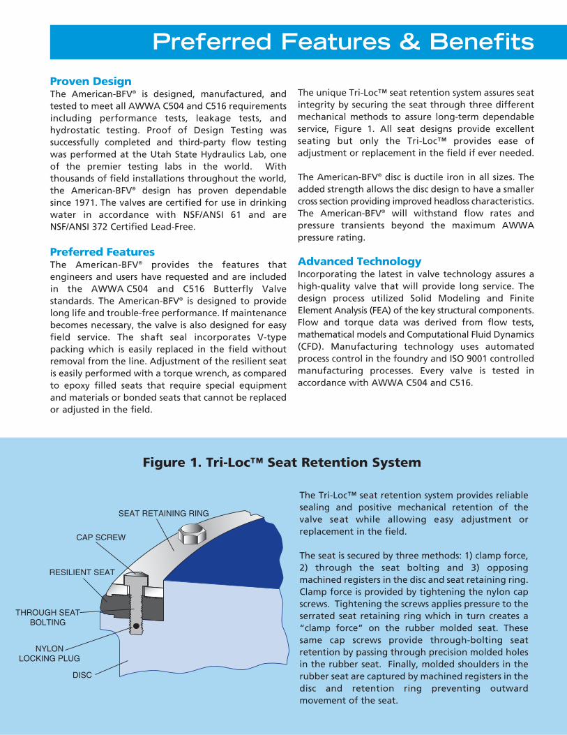
The unique Tri-Loc™ seat retention system assures seatintegrity by securing the seat through three differentmechanical methods to assure long-term dependableservice, Figure 1. All seat designs provide excellentseating but only the Tri-Loc™ provides ease ofadjustment or replacement in the field if ever needed.
The American-BFV® disc is ductile iron in all sizes. Theadded strength allows the disc design to have a smallercross section providing improved headloss characteristics.The American-BFV® will withstand flow rates andpressure transients beyond the maximum AWWApressure rating.
Advanced TechnologyIncorporating the latest in valve technology assures ahigh-quality valve that will provide long service. Thedesign process utilized Solid Modeling and FiniteElement Analysis (FEA) of the key structural components.Flow and torque data was derived from flow tests,mathematical models and Computational Fluid Dynamics(CFD). Manufacturing technology uses automatedprocess control in the foundry and ISO 9001 controlledmanufacturing processes. Every valve is tested inaccordance with AWWA C504 and C516.
Preferred Features & Benefits
SEAT RETAINING RING
RESILIENT SEAT
DISC
CAP SCREW
THROUGH SEATBOLTING
NYLONLOCKING PLUG
Figure 1. Tri-Loc™ Seat Retention System
The Tri-Loc™ seat retention system provides reliablesealing and positive mechanical retention of thevalve seat while allowing easy adjustment orreplacement in the field.
The seat is secured by three methods: 1) clamp force,2) through the seat bolting and 3) opposingmachined registers in the disc and seat retaining ring.Clamp force is provided by tightening the nylon capscrews. Tightening the screws applies pressure to theserrated seat retaining ring which in turn creates a“clamp force” on the rubber molded seat. Thesesame cap screws provide through-bolting seatretention by passing through precision molded holesin the rubber seat. Finally, molded shoulders in therubber seat are captured by machined registers in thedisc and retention ring preventing outwardmovement of the seat.
Valve Construction
4
(CUB
TER
AATW
OF
TIN
FE
E
8
1
2
3
4
5678
10
500
400
300
200
100
807060504030
4”
3”
EET/SECON
BIC METERS PER HOUR)
E
30,0
00
20,0
00
10,0
00
8,00
07,
000
6,00
05,
000
4,00
0
3,00
0
2,00
0
1,00
0
800
700
600
500
FE
20 FEET/SECONDVELOCITY
EETT CVELOC
CO
15 FEET/SECONDVELOCITYETETT C
VELOCO
16 FEETVELVEL
30”
36”24”
20”
18”
16”
14”
12”
10”
8”
6”
20
W(M
ETE
RS
OF 5
0
4
3
2
1.8.7.6.5
.4
.3
200,
000
100,
000
80,0
0070
,000
60,0
0050
,000
40,0
00
15
” 96”
84”
72”60””48”
”42” ”54” ”66”
”78”90”
””
T/SECONDLOCITYEC
LOCSECOO
102102102
”””108108108
HE
AD
LO
SS
1
.2
.3
.4
.5
.6
.7
.8
EEET4 FEET/SECOND
10 FEET/SECONDVELOCITY
EETT CVELO
CO
5 FEET/SECONDVELOCITY
EEVELO
CO
10
5
TYPI
C
1
RAN
GE
SZI
G R
AG
EN
.0
.0
.0
.0
.0
0
.2
.1
GR
ANG
E
TYPI
CL
VE
YC
LL
V
E
C G
Y ZIVEVEVE ELLAAAALALV
YPIC
ASI
ZIN
GVA
LYP
ICA
SIZI
NGC
ASI
ZI
5
SIZI
NG
RAN
GE
SIZI
TER
)AAT
W
0807060504
03
2
1
02
ELOC
TER IN GALLONAATWFLOW OF
10,0
00
8,00
07,
000
6,00
05,
000
4,00
0
3,00
0
2,00
0
1,00
0
800
700
600
500
400
300
200
100
.1
.08
.07
.06
T/SECONDVELOCITYEC
VELOECOCO
NS PER MINUTE
1000
,000
800,
000
700,
000
600,
000
500,
000
400,
000
300,
000
200,
000
100,
000
80,0
0070
,000
60,0
0050
,000
40,0
00
30,0
00
20,0
00
.0
.0
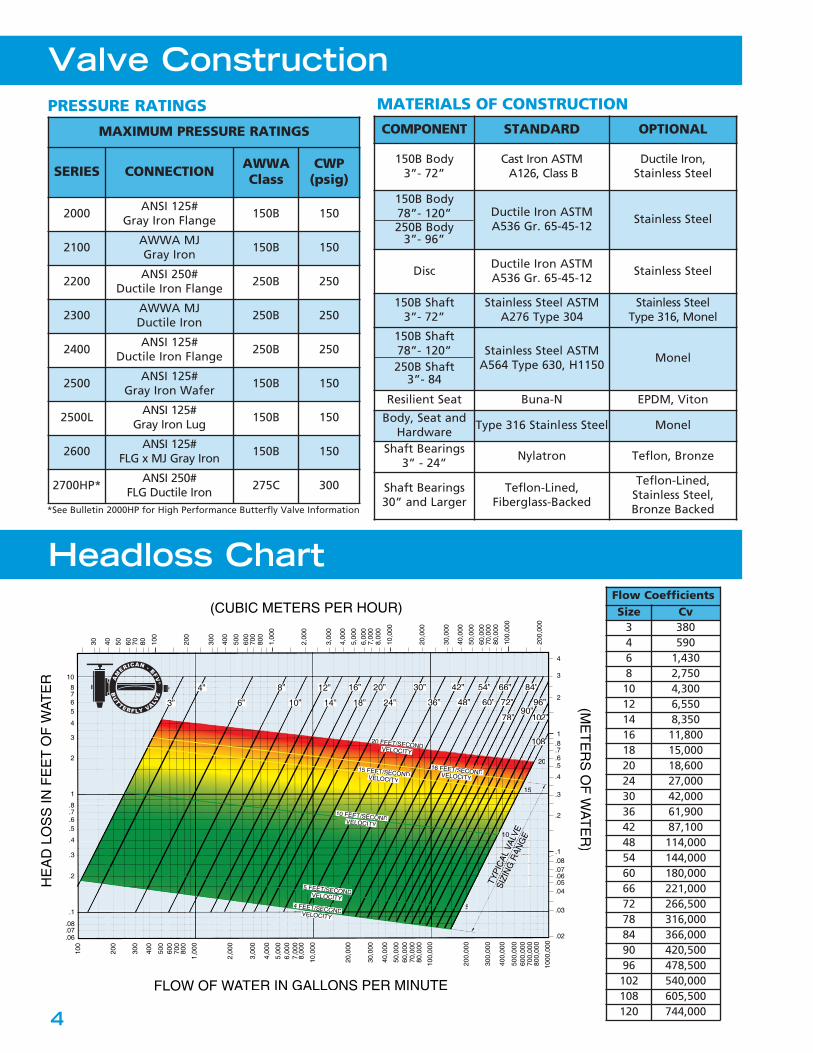
Headloss Chart
PRESSURE RATINGS MATERIALS OF CONSTRUCTION
MAXIMUM PRESSURE RATINGS
SERIES CONNECTION AWWAClass
CWP(psig)
2000ANSI 125#
Gray Iron Flange150B 150
2100AWWA MJGray Iron
150B 150
2200ANSI 250#
Ductile Iron Flange250B 250
2300AWWA MJDuctile Iron
250B 250
2400ANSI 125#
Ductile Iron Flange250B 250
2500ANSI 125#
Gray Iron Wafer150B 150
2500LANSI 125#
Gray Iron Lug150B 150
2600ANSI 125#
FLG x MJ Gray Iron150B 150
2700HP*ANSI 250#
FLG Ductile Iron275C 300
AM
ERICAN - BFV®
BU
TTERFLY VALVE
Flow CoefficientsSize Cv
3 3804 5906 1,4308 2,750
10 4,30012 6,55014 8,35016 11,80018 15,00020 18,60024 27,00030 42,00036 61,90042 87,10048 114,00054 144,00060 180,00066 221,00072 266,50078 316,00084 366,00090 420,50096 478,500102 540,000108 605,500120 744,000
COMPONENT STANDARD OPTIONAL
150B Body3”- 72”
Cast Iron ASTMA126, Class B
Ductile Iron, Stainless Steel
150B Body78”- 120”250B Body
3”- 96”
Ductile Iron ASTMA536 Gr. 65-45-12
Stainless Steel
DiscDuctile Iron ASTMA536 Gr. 65-45-12
Stainless Steel
150B Shaft3”- 72”
Stainless Steel ASTMA276 Type 304
Stainless Steel Type 316, Monel
150B Shaft78”- 120”250B Shaft
3”- 84
Stainless Steel ASTMA564 Type 630, H1150
Monel
Resilient Seat Buna-N EPDM, Viton
Body, Seat andHardware
Type 316 Stainless Steel Monel
Shaft Bearings3” - 24”
Nylatron Teflon, Bronze
Shaft Bearings 30” and Larger
Teflon-Lined,Fiberglass-Backed
Teflon-Lined,Stainless Steel,Bronze Backed*See Bulletin 2000HP for High Performance Butterfly Valve Information
5
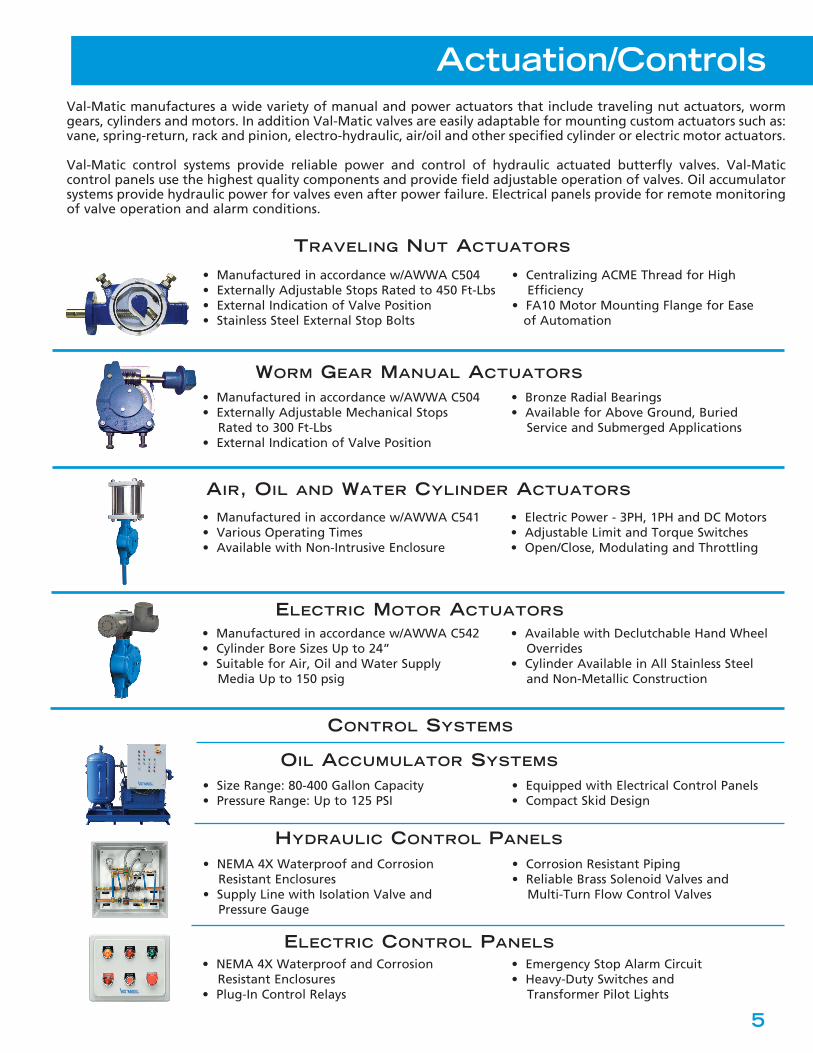
Actuation/Controls
Val-Matic manufactures a wide variety of manual and power actuators that include traveling nut actuators, wormgears, cylinders and motors. In addition Val-Matic valves are easily adaptable for mounting custom actuators such as:vane, spring-return, rack and pinion, electro-hydraulic, air/oil and other specified cylinder or electric motor actuators.
Val-Matic control systems provide reliable power and control of hydraulic actuated butterfly valves. Val-Maticcontrol panels use the highest quality components and provide field adjustable operation of valves. Oil accumulatorsystems provide hydraulic power for valves even after power failure. Electrical panels provide for remote monitoringof valve operation and alarm conditions.
TRAVELING NUT ACTUATORS
WORM GEAR MANUAL ACTUATORS
ELECTRIC MOTOR ACTUATORS
OIL ACCUMULATOR SYSTEMS
AIR, OIL AND WATER CYLINDER ACTUATORS
• Manufactured in accordance w/AWWA C504• Externally Adjustable Stops Rated to 450 Ft-Lbs• External Indication of Valve Position• Stainless Steel External Stop Bolts
• Centralizing ACME Thread for High Efficiency
• FA10 Motor Mounting Flange for Ease of Automation
• Manufactured in accordance w/AWWA C504• Externally Adjustable Mechanical Stops
Rated to 300 Ft-Lbs• External Indication of Valve Position
• Bronze Radial Bearings• Available for Above Ground, Buried
Service and Submerged Applications
• Manufactured in accordance w/AWWA C542• Cylinder Bore Sizes Up to 24”• Suitable for Air, Oil and Water Supply
Media Up to 150 psig
• Available with Declutchable Hand Wheel Overrides
• Cylinder Available in All Stainless Steel and Non-Metallic Construction
• Manufactured in accordance w/AWWA C541• Various Operating Times• Available with Non-Intrusive Enclosure
• Electric Power - 3PH, 1PH and DC Motors• Adjustable Limit and Torque Switches• Open/Close, Modulating and Throttling
• Size Range: 80-400 Gallon Capacity• Pressure Range: Up to 125 PSI
• Equipped with Electrical Control Panels• Compact Skid Design
• NEMA 4X Waterproof and CorrosionResistant Enclosures
• Supply Line with Isolation Valve and Pressure Gauge
• Corrosion Resistant Piping• Reliable Brass Solenoid Valves and
Multi-Turn Flow Control Valves
• NEMA 4X Waterproof and CorrosionResistant Enclosures
• Plug-In Control Relays
• Emergency Stop Alarm Circuit• Heavy-Duty Switches and
Transformer Pilot Lights
HYDRAULIC CONTROL PANELS
ELECTRIC CONTROL PANELS
CONTROL SYSTEMS
6
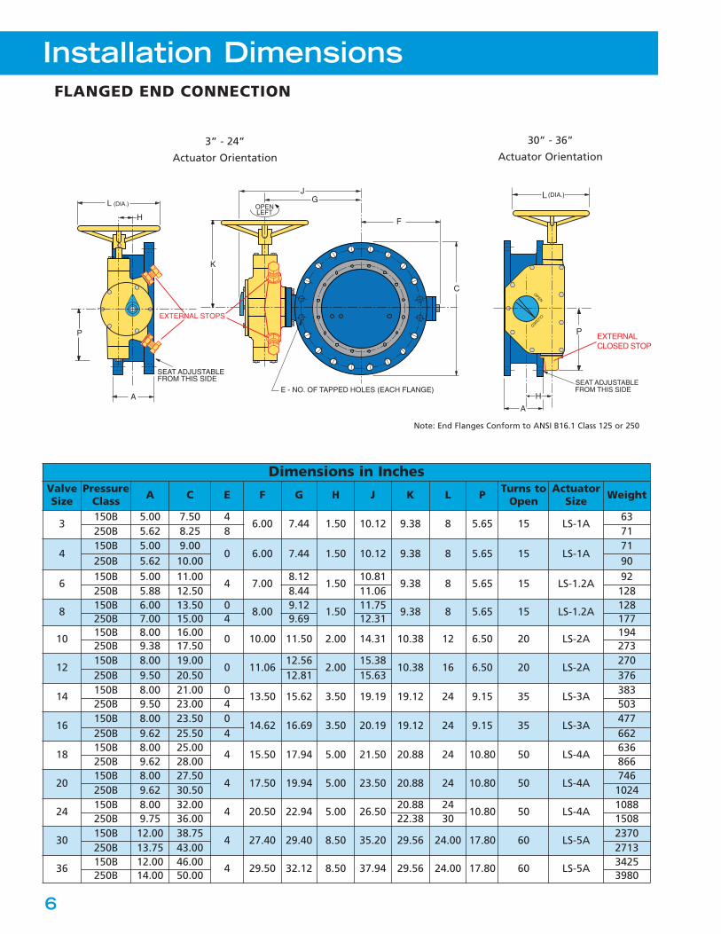
Installation Dimensions
FLANGED END CONNECTION
Dimensions in InchesValveSize
PressureClass A C E F G H J K L P Turns to
OpenActuator
Size Weight
3150B 5.00 7.50 4
6.00 7.44 1.50 10.12 9.38 8 5.65 15 LS-1A63
250B 5.62 8.25 8 71
4150B 5.00 9.00
0 6.00 7.44 1.50 10.12 9.38 8 5.65 15 LS-1A71
250B 5.62 10.00 90
6150B 5.00 11.00
4 7.008.12
1.5010.81
9.38 8 5.65 15 LS-1.2A92
250B 5.88 12.50 8.44 11.06 128
8150B 6.00 13.50 0
8.009.12
1.5011.75
9.38 8 5.65 15 LS-1.2A128
250B 7.00 15.00 4 9.69 12.31 177
10150B 8.00 16.00
0 10.00 11.50 2.00 14.31 10.38 12 6.50 20 LS-2A194
250B 9.38 17.50 273
12150B 8.00 19.00
0 11.0612.56
2.0015.38
10.38 16 6.50 20 LS-2A270
250B 9.50 20.50 12.81 15.63 376
14150B 8.00 21.00 0
13.50 15.62 3.50 19.19 19.12 24 9.15 35 LS-3A383
250B 9.50 23.00 4 503
16150B 8.00 23.50 0
14.62 16.69 3.50 20.19 19.12 24 9.15 35 LS-3A477
250B 9.62 25.50 4 662
18150B 8.00 25.00
4 15.50 17.94 5.00 21.50 20.88 24 10.80 50 LS-4A636
250B 9.62 28.00 866
20150B 8.00 27.50
4 17.50 19.94 5.00 23.50 20.88 24 10.80 50 LS-4A746
250B 9.62 30.50 1024
24150B 8.00 32.00
4 20.50 22.94 5.00 26.5020.88 24
10.80 50 LS-4A1088
250B 9.75 36.00 22.38 30 1508
30150B 12.00 38.75
4 27.40 29.40 8.50 35.20 29.56 24.00 17.80 60 LS-5A2370
250B 13.75 43.00 2713
36150B 12.00 46.00
4 29.50 32.12 8.50 37.94 29.56 24.00 17.80 60 LS-5A3425
250B 14.00 50.00 3980
30” - 36”
Actuator Orientation3” - 24”
Actuator Orientation
A
SEAT ADJUSTABLEFROM THIS SIDE
P
F
C
E - NO. OF TAPPED HOLES (EACH FLANGE)
EXTERNAL STOPS
SEAT ADJUSTABLEFROM THIS SIDE
A
L
H
OPEN
CLOSED
P
(DIA.)
EXTERNALCLOSED STOP
L (DIA.)
H
K
OPENLEFT
JG
Note: End Flanges Conform to ANSI B16.1 Class 125 or 250
7
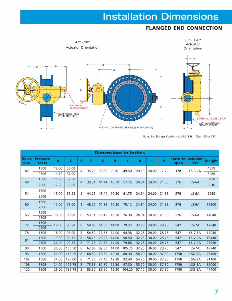
Installation DimensionsFLANGED END CONNECTION
96” - 120”Actuator
Orientation
Dimensions in InchesValveSize
PressureClass A C E F G H J K L P Turns to
OpenActuator
Size Weight
42150B 12.00 53.00
4 35.25 35.88 8.50 49.50 20.13 24.00 17.75 178 LS-5.2A4559
250B 14.12 57.00 5489
48150B 15.00 59.50
4 39.31 41.44 10.50 57.75 24.94 24.00 21.88 276 LS-6A6950
250B 17.50 65.00 8510
54150B
15.00 66.25 8 44.25 45.44 10.50 61.75 24.94 24.00 21.88 276 LS-6A 9280250B
60150B
15.00 73.00 8 48.25 51.88 10.50 70.12 24.94 24.00 21.88 276 LS-6A 12900250B
66150B
18.00 80.00 8 53.31 58.12 10.50 76.38 24.94 24.00 21.88 276 LS-6A 14840250B
72150B
18.00 86.50 8 59.00 61.00 14.00 79.25 32.25 24.00 28.75 547 LS-7A 17840250B
78 150B 18.00 93.00 8 54.50 73.63 14.00 94.38 32.25 24.00 28.75 547 LS-7.3A 14040
84150B 19.00 99.75 8 58.75 76.25 14.00 98.50 32.25 30.00 28.75 547 LS-7.2A 16440250B 24.00 99.75 8 71.25 71.62 14.00 79.88 32.25 24.00 28.75 547 LS-7.2A 27060
90 150B 20.00 106.50 8 62.88 82.50 14.00 105.75 32.25 36.00 28.75 547 LS-7A 19740
96 150B 21.00 113.25 8 68.50 73.30 12.30 88.30 54.20 30.00 37.30 1750 LSG-8A 27400
102 150B 24.00 120.00 8 71.70 77.40 12.30 92.40 54.20 30.00 37.30 1750 LSG-8A 31100
108 150B 24.00 126.75 8 75.38 82.30 12.30 97.30 55.70 30.00 37.30 1750 LSG-8A 35000120 150B 26.00 132.75 8 83.30 89.20 12.30 104.20 57.10 30.00 37.30 1750 LSG-8A 47400
42” - 90”
Actuator Orientation
EXTERNALCLOSED STOPS
K
SEAT ADJUSTABLEFROM THIS SIDE
OPENCLOSED
A
H
OPEN
P
C
E - NO. OF TAPPED HOLES (EACH FLANGE)
G F
L
J
SEAT ADJUSTABLEFROM THIS SIDE
A
K
P
H
EXTERNAL CLOSED STOP
Note: End Flanges Conform to ANSI B16.1 Class 125 or 250
8
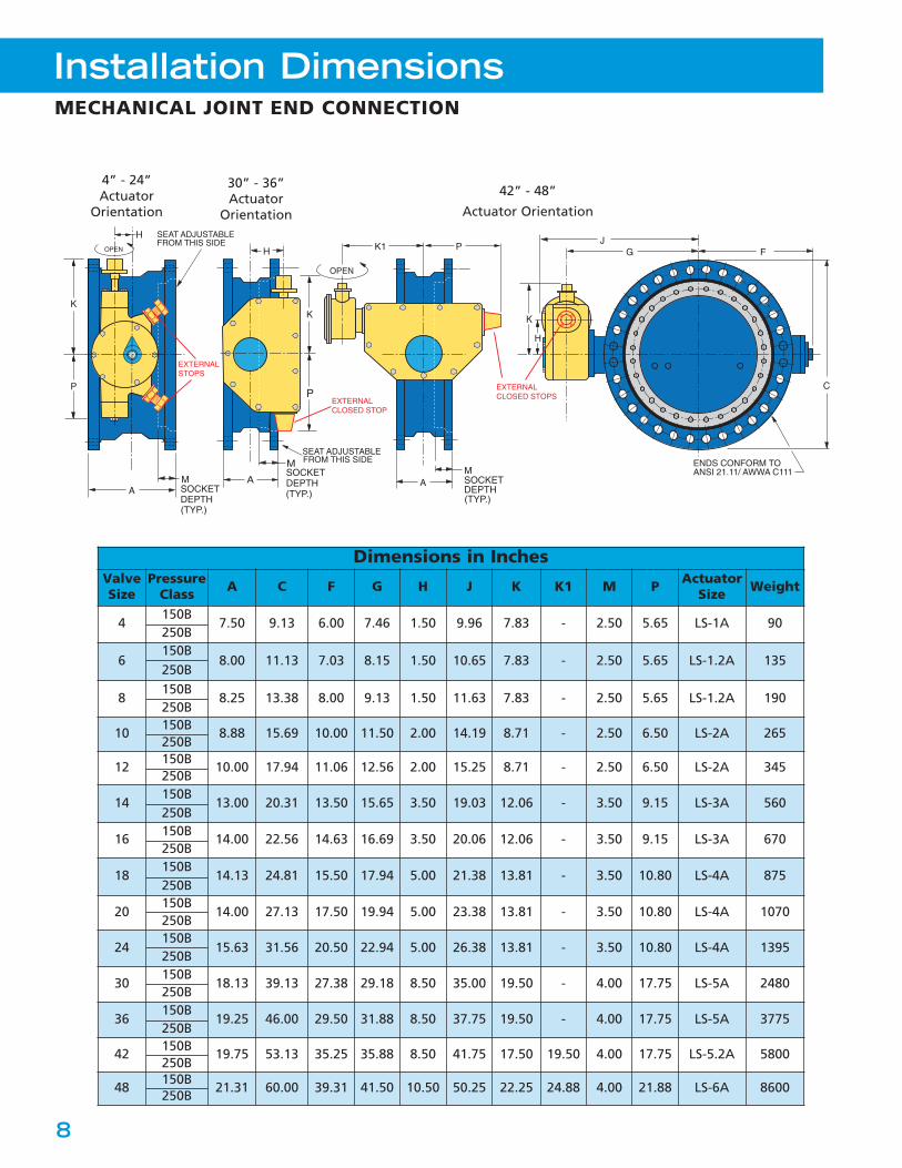
Installation DimensionsMECHANICAL JOINT END CONNECTION
A
OPEN
MSOCKETDEPTH
(TYP.)
SEAT ADJUSTABLEFROM THIS SIDE
P
K
H
A
H
MSOCKETDEPTH
(TYP.)
SEAT ADJUSTABLEFROM THIS SIDE
P EXTERNALCLOSED STOP
K
K1 P
A
OPEN
MSOCKETDEPTH
(TYP.)
F
C
GJ
ENDS CONFORM TOANSI 21.11/ AWWA C111
K
H
EXTERNALSTOPS
EXTERNALCLOSED STOPS
Dimensions in InchesValveSize
PressureClass A C F G H J K K1 M P Actuator
Size Weight
4150B
7.50 9.13 6.00 7.46 1.50 9.96 7.83 - 2.50 5.65 LS-1A 90250B
6150B
8.00 11.13 7.03 8.15 1.50 10.65 7.83 - 2.50 5.65 LS-1.2A 135250B
8150B
8.25 13.38 8.00 9.13 1.50 11.63 7.83 - 2.50 5.65 LS-1.2A 190250B
10150B
8.88 15.69 10.00 11.50 2.00 14.19 8.71 - 2.50 6.50 LS-2A 265250B
12150B
10.00 17.94 11.06 12.56 2.00 15.25 8.71 - 2.50 6.50 LS-2A 345250B
14150B
13.00 20.31 13.50 15.65 3.50 19.03 12.06 - 3.50 9.15 LS-3A 560250B
16150B
14.00 22.56 14.63 16.69 3.50 20.06 12.06 - 3.50 9.15 LS-3A 670250B
18150B
14.13 24.81 15.50 17.94 5.00 21.38 13.81 - 3.50 10.80 LS-4A 875250B
20150B
14.00 27.13 17.50 19.94 5.00 23.38 13.81 - 3.50 10.80 LS-4A 1070250B
24150B
15.63 31.56 20.50 22.94 5.00 26.38 13.81 - 3.50 10.80 LS-4A 1395250B
30150B
18.13 39.13 27.38 29.18 8.50 35.00 19.50 - 4.00 17.75 LS-5A 2480250B
36150B
19.25 46.00 29.50 31.88 8.50 37.75 19.50 - 4.00 17.75 LS-5A 3775250B
42150B
19.75 53.13 35.25 35.88 8.50 41.75 17.50 19.50 4.00 17.75 LS-5.2A 5800250B
48150B
21.31 60.00 39.31 41.50 10.50 50.25 22.25 24.88 4.00 21.88 LS-6A 8600250B
42” - 48”
Actuator Orientation
30” - 36”Actuator
Orientation
4” - 24”Actuator
Orientation
9
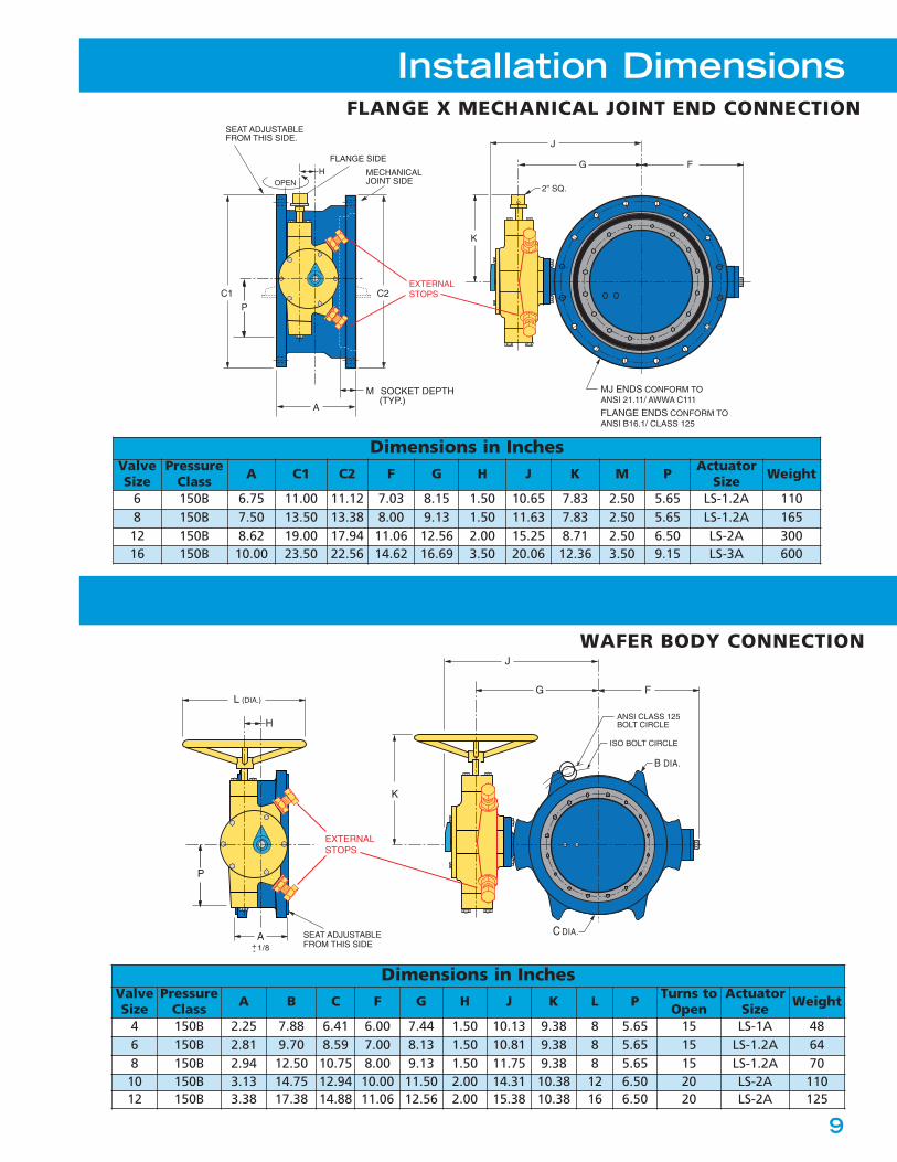
Installation DimensionsFLANGE X MECHANICAL JOINT END CONNECTION
Dimensions in InchesValveSize
PressureClass A C1 C2 F G H J K M P Actuator
Size Weight
6 150B 6.75 11.00 11.12 7.03 8.15 1.50 10.65 7.83 2.50 5.65 LS-1.2A 1108 150B 7.50 13.50 13.38 8.00 9.13 1.50 11.63 7.83 2.50 5.65 LS-1.2A 16512 150B 8.62 19.00 17.94 11.06 12.56 2.00 15.25 8.71 2.50 6.50 LS-2A 30016 150B 10.00 23.50 22.56 14.62 16.69 3.50 20.06 12.36 3.50 9.15 LS-3A 600
Dimensions in InchesValveSize
PressureClass A B C F G H J K L P Turns to
OpenActuator
Size Weight
4 150B 2.25 7.88 6.41 6.00 7.44 1.50 10.13 9.38 8 5.65 15 LS-1A 486 150B 2.81 9.70 8.59 7.00 8.13 1.50 10.81 9.38 8 5.65 15 LS-1.2A 648 150B 2.94 12.50 10.75 8.00 9.13 1.50 11.75 9.38 8 5.65 15 LS-1.2A 7010 150B 3.13 14.75 12.94 10.00 11.50 2.00 14.31 10.38 12 6.50 20 LS-2A 11012 150B 3.38 17.38 14.88 11.06 12.56 2.00 15.38 10.38 16 6.50 20 LS-2A 125
FG
K
L (DIA.)
J
A SEAT ADJUSTABLEFROM THIS SIDE+
- 1/8
C DIA.
ANSI CLASS 125BOLT CIRCLE
ISO BOLT CIRCLE
B DIA.
P
H
EXTERNALSTOPS
A
OPEN
M SOCKET DEPTH (TYP.)
SEAT ADJUSTABLEFROM THIS SIDE.
C2C1
FLANGE SIDE
MECHANICALJOINT SIDE
P
FG
K
2” SQ.
J
MJ ENDS CONFORM TOANSI 21.11/ AWWA C111
FLANGE ENDS CONFORM TOANSI B16.1/ CLASS 125
H
EXTERNALSTOPS
WAFER BODY CONNECTION
10
Installation Dimensions
OPEN
ExtensionStem
Ground LevelPosition IndicatorFloor Stand
Stem Guide
Chainwheel
Extended Bonnet“T” Wrench
AccessoriesSpace limitations and application specifics often require special accessories. In addition to thoseshown below, Val-Matic offers a wide range of accessories to meet your application requirements.Please consult factory for assistance.
LUG BODY CONNECTION
TAPPED THROUGH
ØC
FG
J
K
H
ØB
T
A(TYP)
ØD
EXTERNALSTOPS
Dimensions in InchesValveSize
PressureClass A B C D F G H J K T Turns to
OpenActuator
Size Wt
4 150B 2.25 7.50 9.00 6.41 6.00 8.90 1.50 11.60 7.83 0.80 15 LS-1A 696 150B 2.81 9.50 11.00 8.59 7.00 9.90 1.50 12.60 7.83 1.60 15 LS-1.2A 898 150B 2.93 11.75 13.50 10.75 8.00 11.10 1.50 13.80 7.83 2.50 15 LS-1.2A 123
10 150B 3.23 14.25 16.00 12.94 10.00 12.80 2.00 15.60 8.71 3.30 20 LS-2A 17512 150B 3.55 17.00 19.00 14.88 11.10 14.30 2.00 17.10 8.71 4.20 20 LS-2A 253
11
SpecificationSCOPE1.1 This specification covers the design, manufacture, and
testing of AWWA Class 150B (3”-144”) and AWWA Class250B (3”-96”) butterfly valves.
STANDARDS AND APPROVALS2.1 The valves shall be designed, manufactured and tested in
accordance with American Water Works AssociationStandard ANSI/AWWA C504 and C516.
2.2 The valves shall be certified to NSF/ANSI 61 DrinkingWater System Components - Health Effects and certifiedto be Lead-Free in accordance with NSF/ANSI 372.
2.3 Manufacturer shall have a quality management systemthat is certified to ISO 9001 by an accredited, certifyingbody.
CONNECTIONS3.1 Flanged end connections shall fully conform with ANSI
B16.1 for Class 125, Class 250 iron flanges, or AWWA C207Class D. Both 125 and 250 flanges shall be flat faced.
3.2 Mechanical Joint end connections shall fully conform withANSI/AWWA C111/A21.11.
3.3 Wafer end connections shall be designed for installation between ANSI B16.1 Class 125 iron flanges or between ISO 7005-2 PN10 or PN16 flanges.
DESIGN4.1 The valve shafts shall be of the through-type for sizes 3”-
24”. 30” and larger shall be of the stub type design.Shafts shall be locked to the disc by O-ring sealed taperpins retained with stainless steel nuts. Through-typeshafts shall be supplied on 30” and larger valves whenspecified.
4.2 The valve discs shall be of the solid type without externalribs or vanes to obstruct flow.
4.3 Resilient seats shall be located on the valve disc and shallprovide a 360° continuous, uninterrupted seating surface.Seats shall be mechanically retained with a stainless steelretaining ring and stainless steel cap screws which shallpass through both the resilient seat and the retainingring. The retaining ring shall be continuous or investmentcast with overlapping sections, serrated grooves, andshoulders providing a Tri-Loc® system. The resilient seat’smating surface shall be to a 360° continuous,uninterrupted stainless steel body seat ring. Resilientseats shall be field adjustable and replaceable withoutremoving the valve from the line and shall not requireepoxy, syringes, needles or pressure vessels to replace oradjust.
4.4 The sleeve bearings shall be provided in the valve hubsand shall be self-lubricating nylatron or teflon lined,fiberglass backed.
4.5 The thrust bearings shall be provided and shall beadjustable on valves 30” and larger.
4.6 The shaft seals shall be of the V-type and shall be replace- able without removal of the valve from the line or the shaft from the valve.
MATERIALS5.1 Body: Class 150B valve bodies shall be ASTM A126, Class B
gray iron or ASTM A536 Grade 65-45-12 ductile iron. Class250B valve bodies shall be ASTM A536 Grade 65-45-12ductile iron.
5.2 Disc: Valve disc shall be ASTM A536 Grade 65-45-12ductile iron.
5.3 Shafts: Shafts shall be ASTM A276 type 304, or ASTMA564, Type 630 Stainless Steel.
5.4 Seat: Resilient seat shall be Buna-N and mate to a Type 316 Stainless Steel body seat ring.5.5 Hardware: All seat retaining hardware shall be Type 316
stainless steel.
ACTUATION6.1 Manual, electric or cylinder actuation shall be provided as
specified.6.2 Manual actuators shall be of the traveling nut design with
characterized closure per AWWA C504 and equippedwith externally adjustable closed position stops capableof withstanding 450 ft-lbs. Actuators shall be lubricatedwith EP-2 grease and fully enclosed in an iron housingsealed against the entry of water. Buried service actuatorsshall be packed with grease and sealed for temporarysubmergence to 20 feet of water. Exposed input shaftsshall be electroless nickel plated or stainless steel.
6.3 Cylinder actuators shall be traveling nut design withcharacterized closure sized to position the valve with anair, water or oil supply pressure of 80-150 psi and built inaccordance with AWWA C541. The rotating mechanismwill consist of a lever and traveling nut directly connectedto the cylinder rod. The cylinder rod, heads and barrelshall be constructed of stainless steel or non-metallicmaterial for water service. Rod and piston seals shall be ofthe self-adjustable, wear-compensating type. The pistonshall be one-piece with a wear strip.
6.4 Motor actuators shall be furnished in accordance withAWWA C542 for Power Actuators and factory tested onthe production valve. The motor unit shall be mounted toa self-locking traveling nut actuator with characterizedclosure and externally adjustable closed stop. The motoractuator assembly shall be designed for open/close servicewith a minimum operating time of 60 sec. The motor unitshall be furnished with a position indicator, independentlyadjustable, 15-amp limit switches, and adjustable torquesensors to protect the valve indicator. A handwheel witha declutch lever shall be provided so that the handwheeldoes not rotate during electrical operation. Motors shallbe sized with a 1.5 safety factor and a power supply of230/460V, three phase, 60 Hz AC. Electrical operation shallinclude Local-Off-Remote selector switch, localOpen/Close push buttons and position indication lamps.
OPTIONS7.1 Optional body material is ASTM A536, Grade 65-45-12
ductile iron.7.2 Optional shaft material is ASTM A276, Type 316 stainless steel.7.3 Optional manual actuator for submerged service shall be packed with grease and sealed for continuous submergence to 30 feet of water. All fasteners shall be stainless steel and all the exposed input shafts shall be electroless nickel plated or stainless steel.7.4 Optional resilient seat material is EPDM.
MANUFACTURE8.1 The valve exteriors for above ground service shall be
coated with a universal, alkyd primer. Valve exteriors forburied service shall be coated with an epoxy coating.Valve interiors shall be coated with an NSF/ANSI 61 epoxycoating approved for potable water. Fusion bondedepoxy shall be supplied on the exterior and interior whenspecified.
8.2 Butterfly Valves shall be Val-Matic® Series 2000 as manufactured by Val-Matic® Valve & Mfg. Coporation, Elmhurst, IL. USA or approved equal.
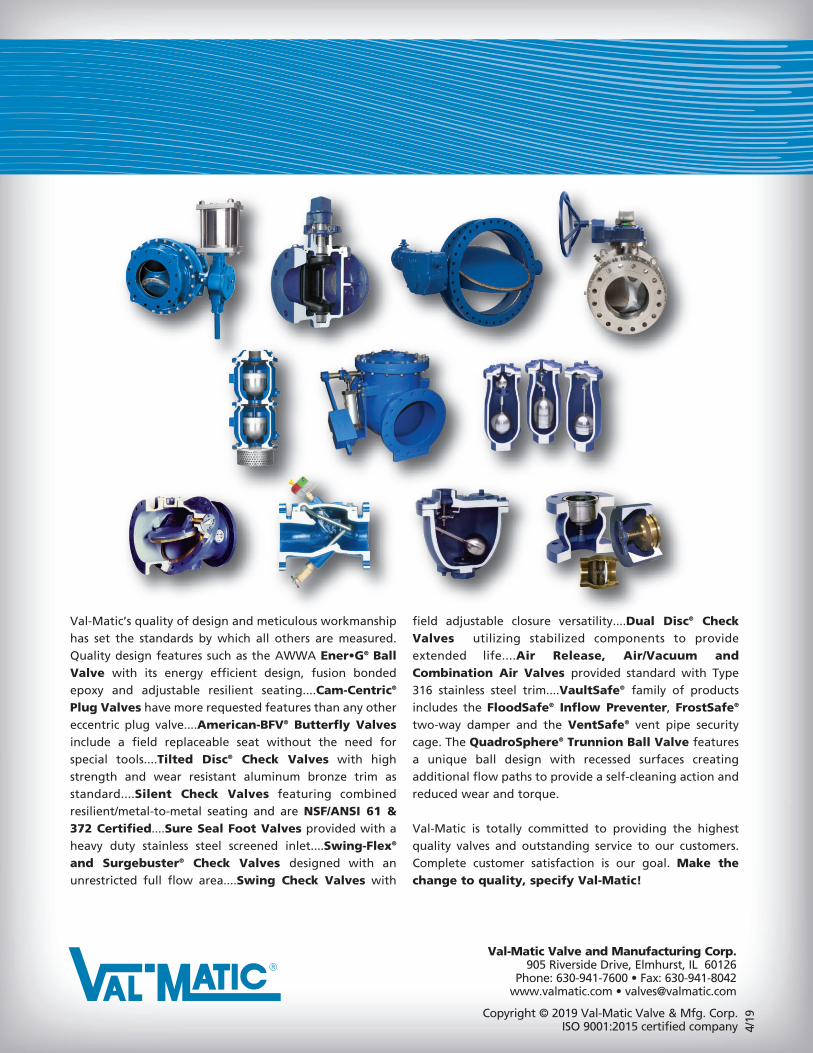
Val-Matic’s quality of design and meticulous workmanshiphas set the standards by which all others are measured.Quality design features such as the AWWA Ener•G® BallValve with its energy efficient design, fusion bondedepoxy and adjustable resilient seating....Cam-Centric®
Plug Valves have more requested features than any othereccentric plug valve....American-BFV® Butterfly Valvesinclude a field replaceable seat without the need forspecial tools....Tilted Disc® Check Valves with highstrength and wear resistant aluminum bronze trim asstandard....Silent Check Valves featuring combinedresilient/metal-to-metal seating and are NSF/ANSI 61 &372 Certified....Sure Seal Foot Valves provided with aheavy duty stainless steel screened inlet....Swing-Flex®
and Surgebuster® Check Valves designed with anunrestricted full flow area....Swing Check Valves with
field adjustable closure versatility....Dual Disc® CheckValves utilizing stabilized components to provideextended life....Air Release, Air/Vacuum andCombination Air Valves provided standard with Type316 stainless steel trim....VaultSafe® family of productsincludes the FloodSafe® Inflow Preventer, FrostSafe®
two-way damper and the VentSafe® vent pipe securitycage. The QuadroSphere® Trunnion Ball Valve featuresa unique ball design with recessed surfaces creatingadditional flow paths to provide a self-cleaning action andreduced wear and torque.
Val-Matic is totally committed to providing the highestquality valves and outstanding service to our customers.Complete customer satisfaction is our goal. Make thechange to quality, specify Val-Matic!
Copyright © 2019 Val-Matic Valve & Mfg. Corp.ISO 9001:2015 certified company
Val-Matic Valve and Manufacturing Corp.905 Riverside Drive, Elmhurst, IL 60126
Phone: 630-941-7600 • Fax: 630-941-8042www.valmatic.com • [email protected]
4/19