Embed Size (px)
DESCRIPTION
b
Citation preview

BUSINESS REQUIREMENT
DOCUMENT FOR
INTERNSHIP MANAGEMENT APPLICATION
Submitted by:-
TEAM SURMURR

1. INTRODUCTION
1.1 OverviewThis document provides a comprehensive description on how the project, Development of an Internship Management System and Two Way Database synchronization was conducted, explaining specifically how the project was analyze, design and eventually implemented.The project involves two independent systems (an Internship Management System and an Online Application Portal) which have been developed separately and how data is synchronized between their databases.
1.2 Problem StatementIn today’s world where information and communication technology systems have become ubiquitous with different vendors providing various kinds of management software with different range of applicability, it is rather surprising that internship at AES-SONEL is managed without one. It is easy to find a staff typing each applicant’s internship offer letter on Microsoft word. Given the vast number of applicant’s that are accepted per month or year, this approach is laborious. Furthermore, the usage of Microsoft Excel as a database for storing records further makes the whole process very difficult to manage and unwieldy.
In addition, the manual creation of various reports not only makes the process time consuming
but also is wastage of human resource effort that would have been used to perform other tasks.
Finally, the fact that one cannot apply and check the status of his application online makes the whole process too demanding for applicants who are required in most cases to travel or go to the agency just to submit an application.
This project attempts to provide a solution to these problems.
1.3Report ArchitectureThis project report is organized into five main chapters. The first is the Literature Review, the second is the Methodology, the third is the Requirements Analysis and Specification, the fourth is the Analysis and Design, the fifth is the Implementation.
The Literature Review chapter will give a description of the different methods available to solve the problem, their merits and demerits.
The Methodology chapter will give a combination of the methods by which the project was conducted and controlled, and also, the methods in software development that was applied. Arguments will be provided regarding the method that was chosen.
The Requirements Analysis chapter will provide the requirements of the project, specifically the functional and non functional requirements of the systems.
The Analysis and Design chapter will provide detail description on how the system was analyzed. UML diagrams will be used to show the general view of the system. A description of the User Interface Design, the Information Domain Modeling, the Data Modeling and the Choice of Architecture will be provided.
The Implementation chapter will provide a description on how the system was implemented using the output from the analysis and design phase as input. An explanation of the architecture of implementation will be provided and reasons why the architecture was chosen.
2.LITERATURE REVIEW
This chapter of the report describes the different methods, architectures and frameworks that were considered in order to execute the project. Their merits and demerits are also provided.
2.1. Software Development Approach Considered
In order to analyze, design and implement the software system, two approaches to software development were considered: Object Oriented Approach and Structured Approach.
2.1.1. Object Oriented Approach
The object-oriented approach is a development strategy based on the concept that systems should be built from a collection of reusable parts called objects
2.1.2. Structured (Traditional) Approach
The structured approach is a development strategy based on the concept that a system should be separated into two parts: data (modeled using a data model) and functionality (modeled using a process model). Following the structured approach, you develop applications in which data are separate from behavior both in the design model and in the system implementation
2.2. Architecture of Implementation
Two software architectural patterns were considered: MVC and 3-Tier architecture.
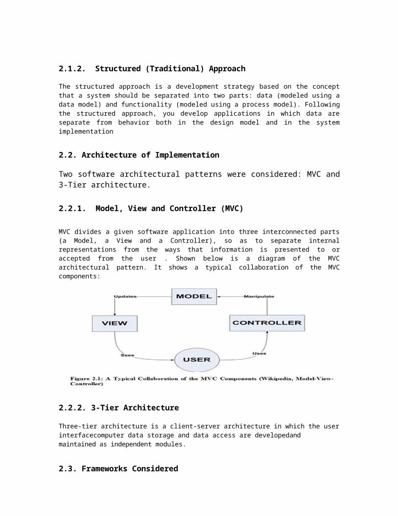
2.2.1. Model, View and Controller (MVC)
MVC divides a given software application into three interconnected parts (a Model, a View and a Controller), so as to separate internal representations from the ways that information is presented to or accepted from the user . Shown below is a diagram of the MVC architectural pattern. It shows a typical collaboration of the MVC components:
2.2.2. 3-Tier Architecture
Three-tier architecture is a client-server architecture in which the user interfacecomputer data storage and data access are developedand maintained as independent modules.
2.3. Frameworks Considered
The programming language used for implementing the application is PHP. PHP was chosen because of the stakeholder’s specification. In this regard, PHP frameworks were considered: CAKE PHP
2.4. Database Synchronization Technology
In order to synchronize the databases of both systems,MySQL replication was considered. MySQL replication enables data from one MySQL database server (the master) to be replicated to one or more MySQL database servers.Replication is asynchronous by default. The slaves need not to be connected permanently to receive updates from the master. Depending on the configuration, the whole database or selected tables within a database can be replicated. Replication is base on the binary logging mechanism. The MySQL instance operating as the master writes updates as “events” to the binary log. Slaves are configured to read the binary log from the master and to execute the events in the binary log on the slave’s local database. Each slave must be configured with information about the master host name, log file name, and position within that file
3. IMPROVEMENTS TO THE EXISTING SYSTEM
This project was initiated mainly to address the problems encountered in the management of internship at any organization. Below are some of the problems that can be identified with the current system and the ways that this project attempts to solve.
The manual creation of each applicant’s internship offer letter using Microsoft Word is a real wastage of time and human resource effort. The new system will offer the possibility to generate this letter automatically.
There is lack of data independence and efficient access with the current system. Records stored on Microsoft Spread sheet in windows may not open properly in Open Office in Linux. The new system will run on any platform efficiently.
The fact that an applicant cannot apply and track his application online makes the whole process too demanding for applicants who are forced to go to the agency just to drop an application. Also, collecting paper documents from applicants can easily lead to the lostof applicants documents considering the vast number of applicants who apply regularly.
With the new system, applicants will be able to apply and check the status of their application online.
Changes made to data cannot easily be seen by other staffs in the same unit and as far as security is concerned, there is the tendency that people without the right grant or permission can easily gain access to the stored data if they manage to gain access to the management staff computer. The new system will employ a unified database, making it easy for changes to be seen by everyone. Also, security will be enforced by granting each user a username and password.
The new system will offer the possibility to track and trace human errors. Also, because many aspects will be automated human error is reduced.
The fact that the current system is not web-based, it is impossible to manage internship remotely. Since the new system is web-based and will run on a webserver, remote access is possible via a network.
The problem of data redundancy is also addressed as records will be stored in a well normalized database. Thus, the new system benefits from the advantages of a database management system.
4. METHODOLOGY ADOPTED
This chapter provides a combination of the methods by which the project was conducted and controlled, and also, the software development method applied. In addition, arguments are provided regarding the methods chosen.
The object oriented approach and the Rational Unified Process (RUP) framework to software development was adopted to analyze, design and implement the software system. Rationale for adopting the object oriented approach and RUP framework is explained below:
4.1.Rationale for Adopting the Object Oriented Approach
The Object Oriented Approach was adopted over the Structured Approach because of the following reasons:
The complexity of this project. My familiarity with the approach.
Much more suitable for this project. The dominance of object oriented paradigm and its related technologies in market and
industry. The technical and theoretical capabilities of the method. The wide acceptance in industry. Wide range of development languages and tools to choose from.
4.2.Rationale for Adopting the Rational Unified Process
RUP framework was adopted over the Agile Unified Process (AUP) framework because of the following reasons:
My familiarity with the framework. My interest in a detailed and well-defined software process.
RUP was much more suitable for this project. AUP encourages frequent client interaction and increase collaboration (good idea), which was not the case in this project as clients were usually very busy. Thus, adopting AUP will have resulted in requirements that will suffer.
4.3. Reasons for Using PHP CAKE Framework
It has been around for a long time and thus is easy to find answers on the web. It has a light footprint.
5. REQUIREMENTS ANALYSIS
This chapter explains specifically how the requirements of the software systems were captured. It provides the functional and non functional requirements of the system.
The requirements for both systems (Internship Management System and Online Application Portal) were captured in the Requirements Analysis and Definition phase of the project. This was done via preparation of questionnaires with sample questions for the interns to answer. Also, meeting sessions were organized for face-to-face conservations with the students. In each meeting session, audio recorder was used to capture the conversation, hence enforcing better requirements capture.
After the requirements were captured, a Software Requirement Specification (SRS) document was produced.
Illustrated below are the functional and non functional requirements of the systems. The following labels are used to prioritize the requirements:
Must have - Refers to those requirements that together create the core functionalities of the system.
Should have - Refers to those requirements that although are not part of the core functionalities, however, they can be very useful and will be implemented if the project schedule allows to do so.
Nice to have - Refers to those requirements that do not play a main role in the functionality of the system, at least at the scope of this project; however, they would give more facilities to the users if the schedule allows them to be implemented.
The labels are given the following prefix: M to “Must have”, S to “Should have” and N to “Nice to have”
5.1. Functional Requirements
Functional requirements are those features of the system by which the system fulfills the core responsibility that is expected to accomplish
5.1.1. Functional Requirements of the Internship Management System (IMS)
The table below shows the functional requirements of the IMS. Each requirement is given an Identification id which will be used as a cross reference in the Use Case Model template to state which requirements the use case satisfies. Also, the requirements are prioritize in order of importance.
Table 5.1: Functional Requirements of the Internship Management System
ID
Functional Requirements Importance
1 To keep and maintain applicant’s information M
2 To keep and maintain intern’s information. M
3 To allow management staff notify applicant’s on the status of their application via applicant’s email.
M
4 To allow management staff notify applicant’s on the status of their application via sms.
M
5 To allow management staff or usetr to search applicant’s by first name, last name or full name
M
6 To allow user to search intern’s by first name,last name or full name M
7 To allow user to review applicant’s curriculum vitae, attestation of registration and recommendation letter
M
8 To allow user to print internship offer letter, internship extension letter and internship attestation in English language.
M
9 To allow user modify his personal profile. M
10 To allow user generate a pdf version of internship offer letter M
11 To keep and maintain internship supervisors information M
12 To keep and maintain signatories information M
13 To keep and maintain different units in the organization. M
14 To allow manager to create or add a new staff to the system. M
15 To automatically generate report on the number of applications received per month, per year or within a given period.
M
16 To automatically generate report on the number applicant’s accepted per month, per year, within a given period, per fields of study, per university, per unit of welcome and per region
M
17 To automatically generate report on the number of internship reports received per month,year or within a given period
M
18 To automatically generate report on the number of intern’s evaluated per month,year,or within a given period of time
M
19 To provide reports on intern’s with an excellent remark M
20 To provide reports on the number of evaluation files received. M
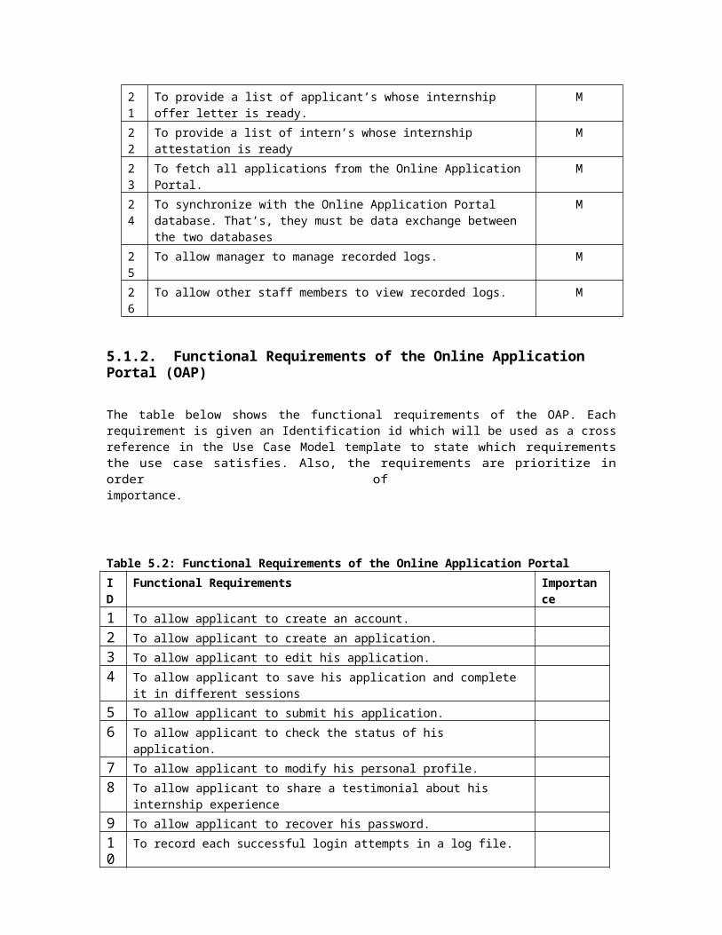
21 To provide a list of applicant’s whose internship offer letter is ready. M
22 To provide a list of intern’s whose internship attestation is ready M
23 To fetch all applications from the Online Application Portal. M

24 To synchronize with the Online Application Portal database. That’s, they must be data exchange between the two databases
M
25 To allow manager to manage recorded logs. M
26 To allow other staff members to view recorded logs. M
5.1.2. Functional Requirements of the Online Application Portal (OAP)
The table below shows the functional requirements of the OAP. Each requirement is given an Identification id which will be used as a cross reference in the Use Case Model template to state which requirements the use case satisfies. Also, the requirements are prioritize in order of importance.
Table 5.2: Functional Requirements of the Online Application Portal
ID Functional Requirements Importance
1 To allow applicant to create an account.
2 To allow applicant to create an application.
3 To allow applicant to edit his application.
4 To allow applicant to save his application and complete it in different sessions
5 To allow applicant to submit his application.
6 To allow applicant to check the status of his application.
7 To allow applicant to modify his personal profile.
8 To allow applicant to share a testimonial about his internship experience
9 To allow applicant to recover his password.
10
To record each successful login attempts in a log file.
11
To allow administrators to login and manage the portal.
12
To allow an admin to add a new admin to the system.
13
To allow an admin to modify his profile.
5.2.1. Non Functional Requirements of the Internship Management System (IMS)
The table below shows the non functional requirements of the IMS. Each non
functional requirement is indicated in the left column, while the right column indicates
what the system must fulfill to satisfy the requirement.

Table 5.3: Non Functional Requirements of the IMS Requirement Category
Description
Performance Requirement
The load time for user interface screen shall take no longer than five seconds
The login information shall be verified within five seconds
Queries shall return results within five seconds
Design Constraints
The Internship Management System shall be a web-based application
Standard Compilance
There shall be consistency in variable name within the system.The graphical user interface shall have a consistent skin
Reliability The Internship Mangement System must be highly reliable and should easily recover from errors
Availability The Internship Management System shall be available 99.99% of time during normal working hours
Security Access to the individual user account will be protected by a user login screen that requires a username and password.To further enhance the security of the system, all passwords will be stored in encrypted formatEach successful login attempt shall be recorded in a log file
Maintainability The system must be easy to maintain
.
5.2.2. Non functional Requirements of the Online Application Portal (OAP)
The table below shows the non functional requirements of the OAP. Each non
functional requirement is indicated in the left column, while the right column
indicates what the system must fulfill to satisfy the requirement.
Table 5.4: Non Functional Requirements of the OAP Requirement Category
Description
Performance The load time for user interface screen shall
Requirement take no longer than five seconds The login information shall be verified within
five seconds Queries shall return results within five seconds
Design Constraints
The Online Application Portal requires each applicant to have an email address in order to create an account
Standard Compilance
There shall be consistency in variable name within the system.The graphical user interface shall have a consistent skin
Reliability The portal must be highly reliable. Instructive messages shall be provided at various places to guide users
Availability The Online Application Portal shall be available all the time
Security Access to the individual user account will be protected by a user login screen that requires a username and password.To further enhance the security of the system, all passwords will be stored in encrypted formatEach successful login attempt shall be recorded in a log file
Maintainability The system must be easy to maintain
6. ANALYSIS AND DESIGN
This chapter provides details on how both systems were analyzed and designed. Analysis
refers to understanding the problem while Design refers to coming out with a blueprint of
the system. Also, this chapter shows how the application will meet the requirements
specified in the Software Requirements Specification (SRS) document. It describes
the rationale for design decisions taken and provides a basis for implementation and
unit test. The Object Oriented Approach and Rational Unified Process (RUP) were used
specifically to analyze and design the system. A detail Software Design Document (SDD)
for each system was produced on a separate document. Both documents are included in the
CD attached to this report.
6.1. Use Case Modeling
Use Case Modeling is a powerful modeling technique that can be used to capture and
organize requirements. Use Case Modeling has two perspectives, a Use Case Diagram
and a Use Case Model template which simplifies the explanation of the use case.
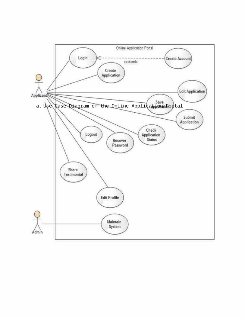
Shown below is the use case diagram for both the Internship Management System
(IMS) and Online Application Portal (OAP).
a. Use Case Diagram of the Online Application Portal
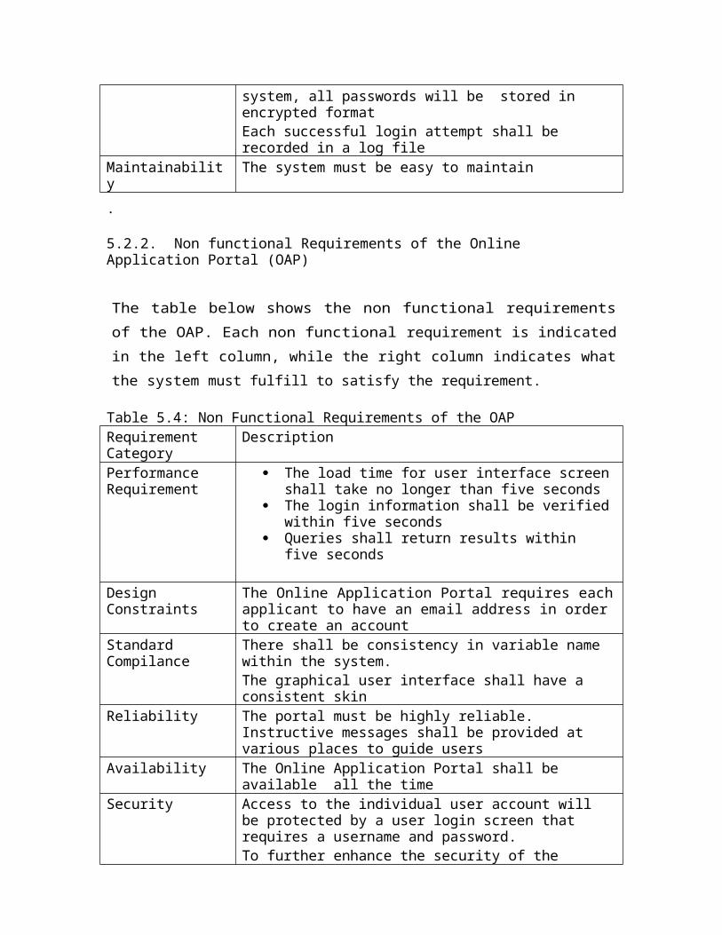
Figure 6.1: Use Case Diagram of the Online Application Portal
b. Use Case Diagram of the Internship Management System

Figure 6.2: Use Case Diagram of the Internship Management System
6.2. User Interface Design
User Interface Design describes the functionality of the system from the user’s perspective.
That is, it explains how the users will use the system to complete all the expected
features and the feedback information that will be displayed for the user. In this case, UML
Activity diagram and State Chart diagram are used to design the UI. Also, following the
diagrams are screen sketches of the major UI elements.
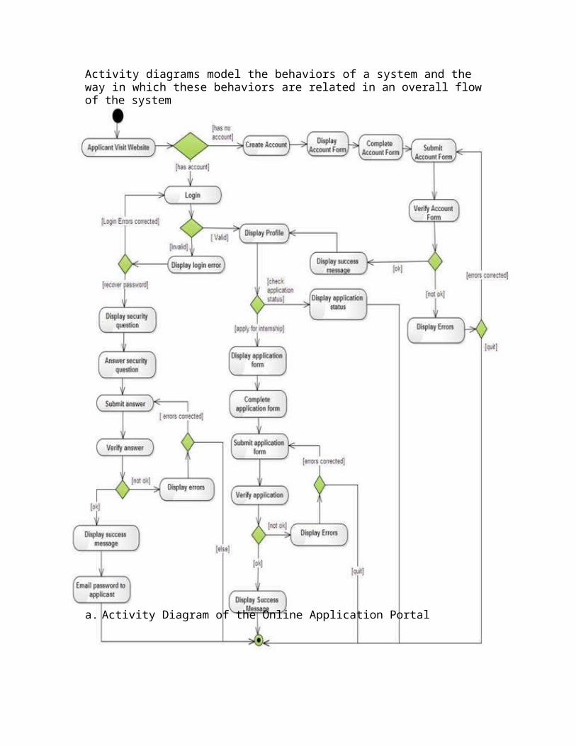
6.2.1. Activity Diagrams
Activity diagrams model the behaviors of a system and the way in which these behaviors are related in an overall flow of the system
a. Activity Diagram of the Online Application Portal
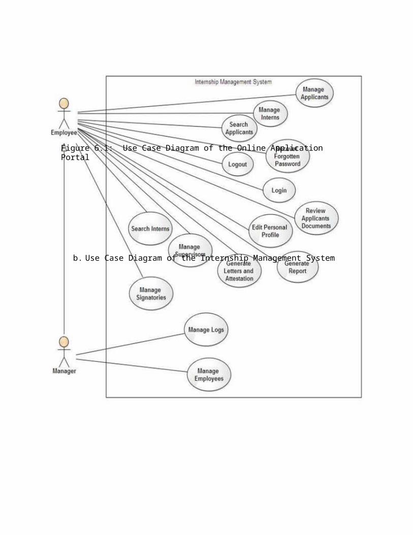
Figure 6.3: Activity Diagram of the OAP
b. Activity Diagram of the Internship Management System

Figure 6.4: Activity Diagram of the IMS (Behavior of an employee and the system)
6.2.2. State Chart Diagrams
State Chart diagram illustrates how an element (often a Class) can move between states, classifying its behavior according to transition triggers and constraining guards. Other aspects of State Chart diagrams further depict and explain movement and behavior
a. State Chart Diagram of the Online Application Portal
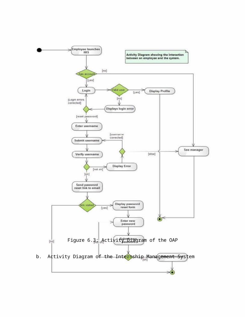
Figure 6.5: State Chart Diagram of the OAP
b. State Chart Diagram of the Internship Management System

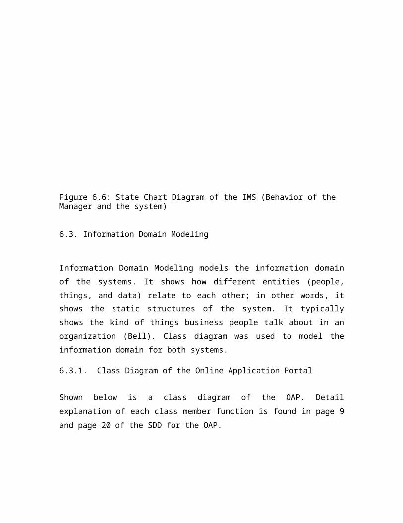
Figure 6.6: State Chart Diagram of the IMS (Behavior of the Manager and the system)
6.3. Information Domain Modeling
Information Domain Modeling models the information domain of the systems. It
shows how different entities (people, things, and data) relate to each other; in other words,
it shows the static structures of the system. It typically shows the kind of things business
people talk about in an organization (Bell). Class diagram was used to model the
information domain for both systems.
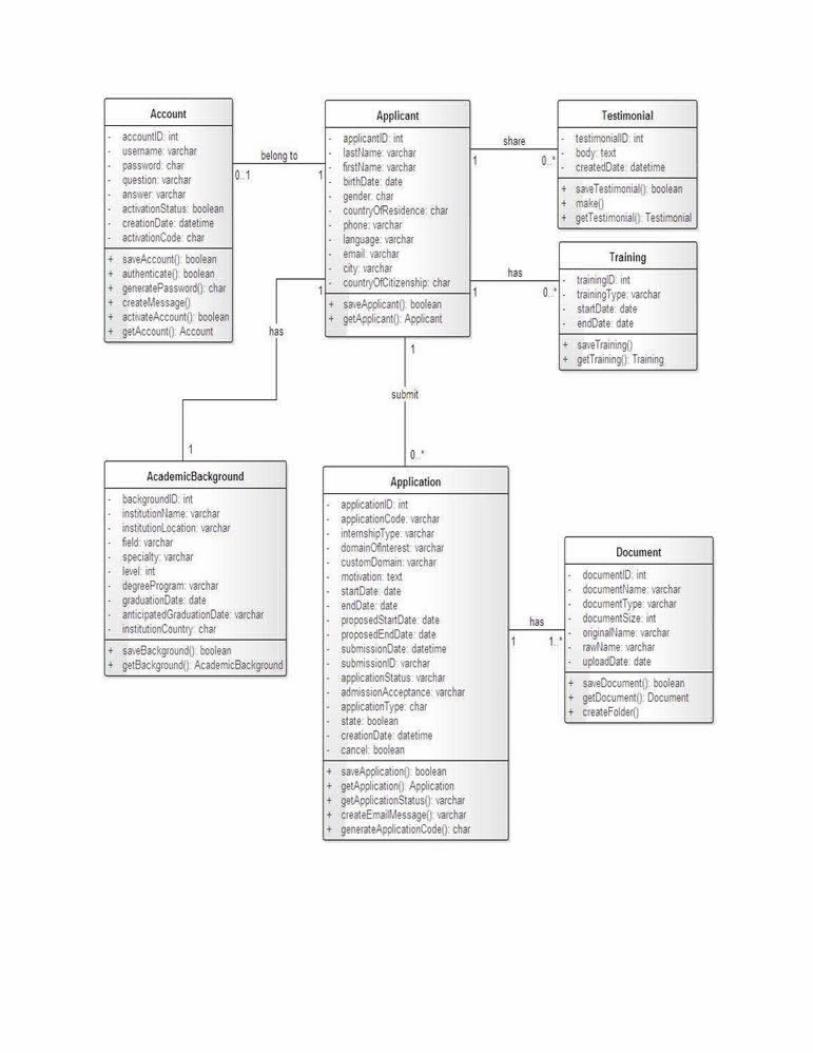
6.3.1. Class Diagram of the Online Application Portal
Shown below is a class diagram of the OAP. Detail explanation of each class member
function is found in page 9 and page 20 of the SDD for the OAP.
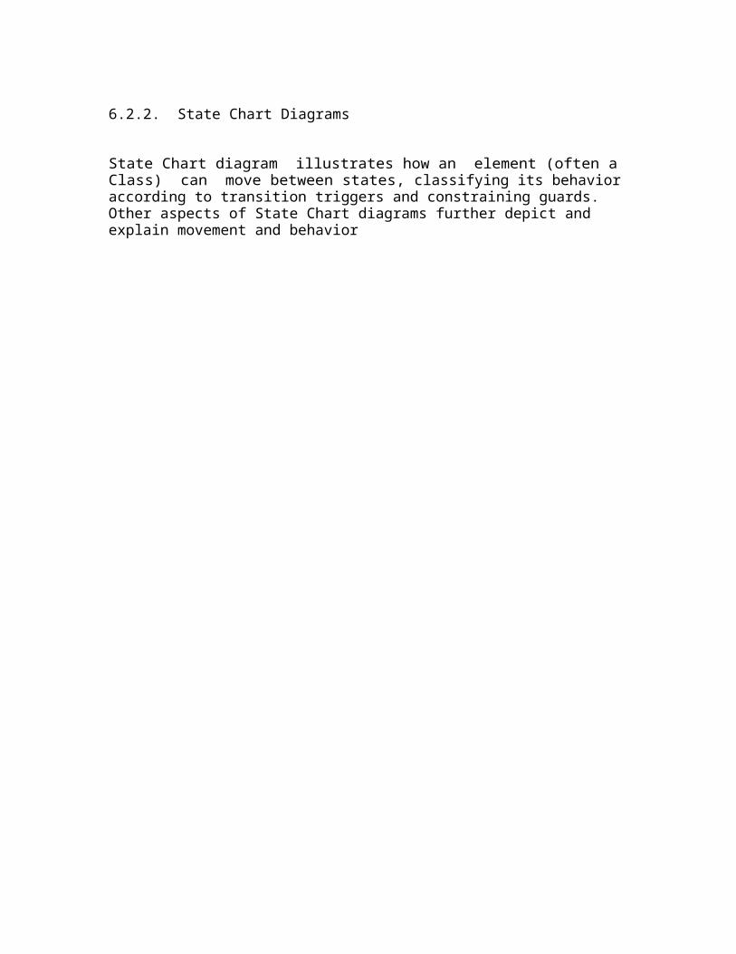

Figure 6.17: Class Diagram of the OAP
6.3.2. Class Diagram of the Internship Management System
Shown below is a class diagram of the IMS.

Figure 6.18: Class Diagram of the IMS
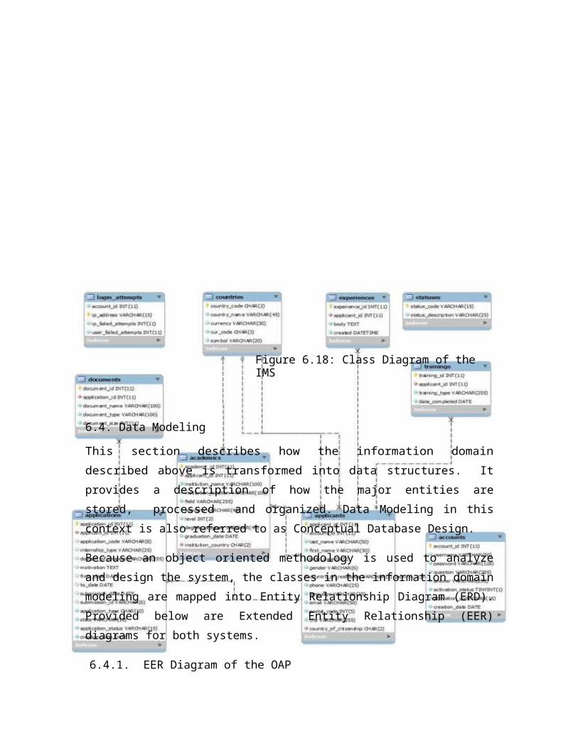
6.4. Data Modeling
This section describes how the information domain described above is transformed
into data structures. It provides a description of how the major entities are stored,
processed and organized. Data Modeling in this context is also referred to as
Conceptual Database Design.
Because an object oriented methodology is used to analyze and design the system, the
classes in the information domain modeling are mapped into Entity Relationship Diagram
(ERD). Provided below are Extended Entity Relationship (EER) diagrams for both
systems.
6.4.1. EER Diagram of the OAP
6.4.2. EER Diagram of the IMS
6.5. Physical Database Design
This refers to transforming the conceptual database design to relational tables. Here,
data dictionary is provided showing the different tables of the application.
6.5.1. Data Dictionary for the Internship Management System
Table 6.1: Sessions Table
Column Type Null Defaultsession_id varchar(40) No 0ip_address varchar(45) No 0user_agent varchar(120) Nolast_activity int(10) No 0user_data Text No
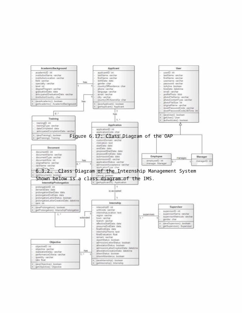
Table 6.2: Academics Table
Column Type Null Default
Links to
academic_id int(11) Noapplicant_id int(11) No Applicants-
>applicant idinstitution_name varchar(100) Noinstitution_location varchar(100) NoField varchar(255) NoSpecialty varchar(45) Yes NULLLevel int(2) Nodegree_program varchar(45) Nograduation_date Date Yes NULLanticipated_graduation_date varchar(15) Yes NULLinstitution_country char(2) No
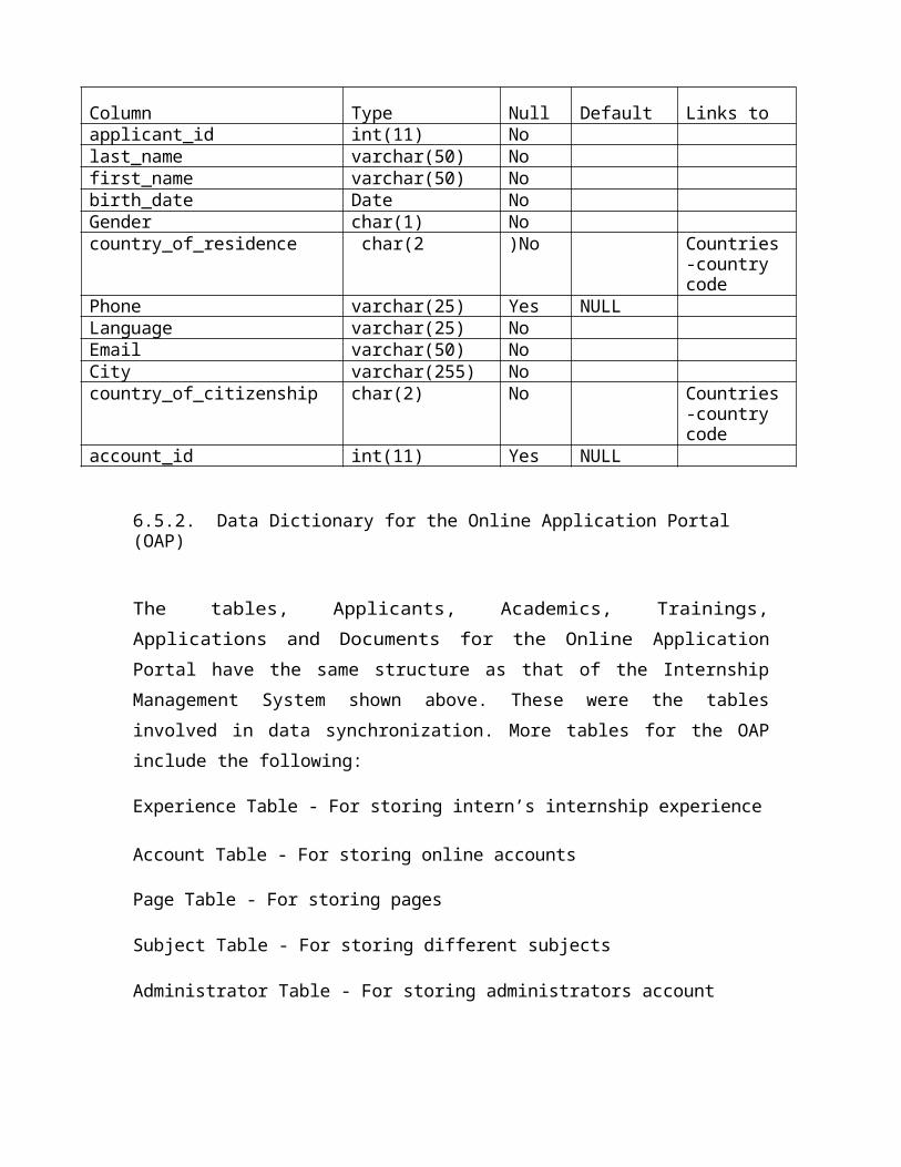
Table 6.3: Applicants Table
6.5.2. Data Dictionary for the Online Application Portal (OAP)
Column Type Null Default Links toapplicant_id int(11) Nolast_name varchar(50) Nofirst_name varchar(50) Nobirth_date Date NoGender char(1) Nocountry_of_residence char(2 )No Countries-
country codePhone varchar(25) Yes NULLLanguage varchar(25) NoEmail varchar(50) NoCity varchar(255) Nocountry_of_citizenship char(2) No Countries-
country codeaccount_id int(11) Yes NULL
The tables, Applicants, Academics, Trainings, Applications and Documents for the
Online Application Portal have the same structure as that of the Internship Management
System shown above. These were the tables involved in data synchronization. More tables
for the OAP include the following:
Experience Table - For storing intern’s internship experience
Account Table - For storing online accounts
Page Table - For storing pages
Subject Table - For storing different subjects
Administrator Table - For storing administrators account
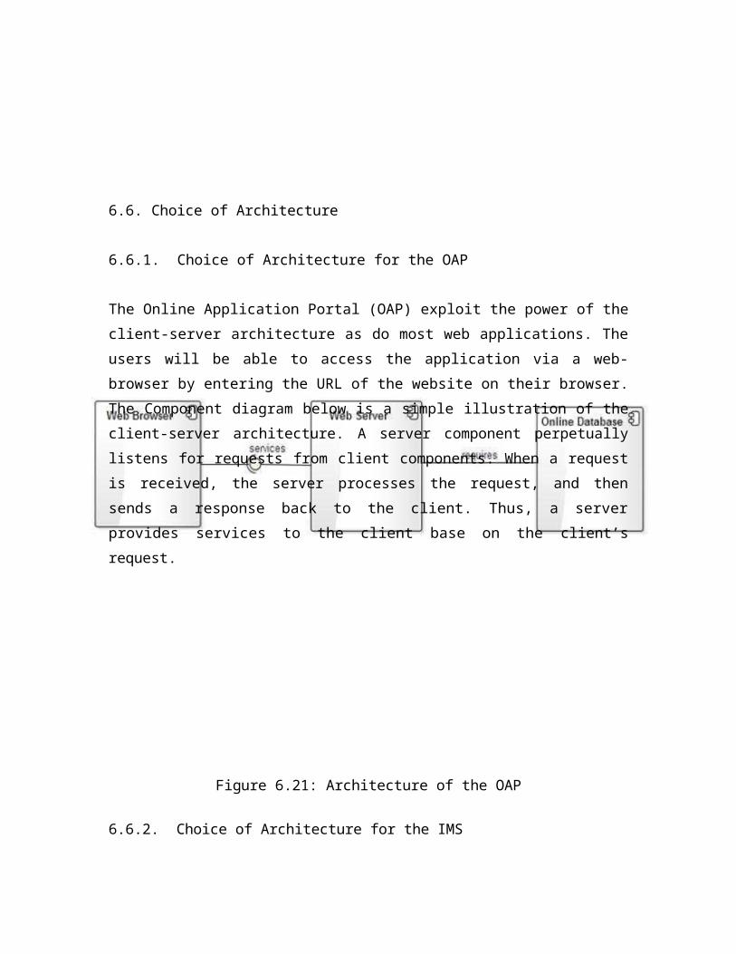
6.6. Choice of Architecture
6.6.1. Choice of Architecture for the OAP
The Online Application Portal (OAP) exploit the power of the client-server architecture
as do most web applications. The users will be able to access the application via a web-
browser by entering the URL of the website on their browser. The Component diagram
below is a simple illustration of the client-server architecture. A server component
perpetually listens for requests from client components. When a request is received, the
server processes the request, and then sends a response back to the client. Thus, a server
provides services to the client base on the client’s request.
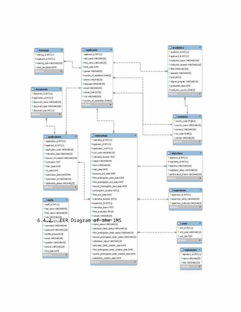
Figure 6.21: Architecture of the OAP
6.6.2. Choice of Architecture for the IMS
The Internship Management System (IMS) exploit the power of the client-server
architecture. Users will be able to access the application via a web-browser. The UML
Component diagram below is a simple illustration of the client-server architecture. A
server component perpetually listens for requests from client components. When a request
is received, the server processes the request, and then sends a response back to the client.
Thus, a server provides services to the client base on the client’s request. The diagram
below depicts two major components represented as module 1 and module 2. Module 1
represents the Internship Management System while modules 2 represent the Online
Application Portal. Within Component 1, are 3 sub-components
which illustrate the client-server architecture of the Internship Management System.
Also, the relation called “synchronization logic” indicates that Component 1 (IMS)
provide the logic for communicating with the Online Application Portal.
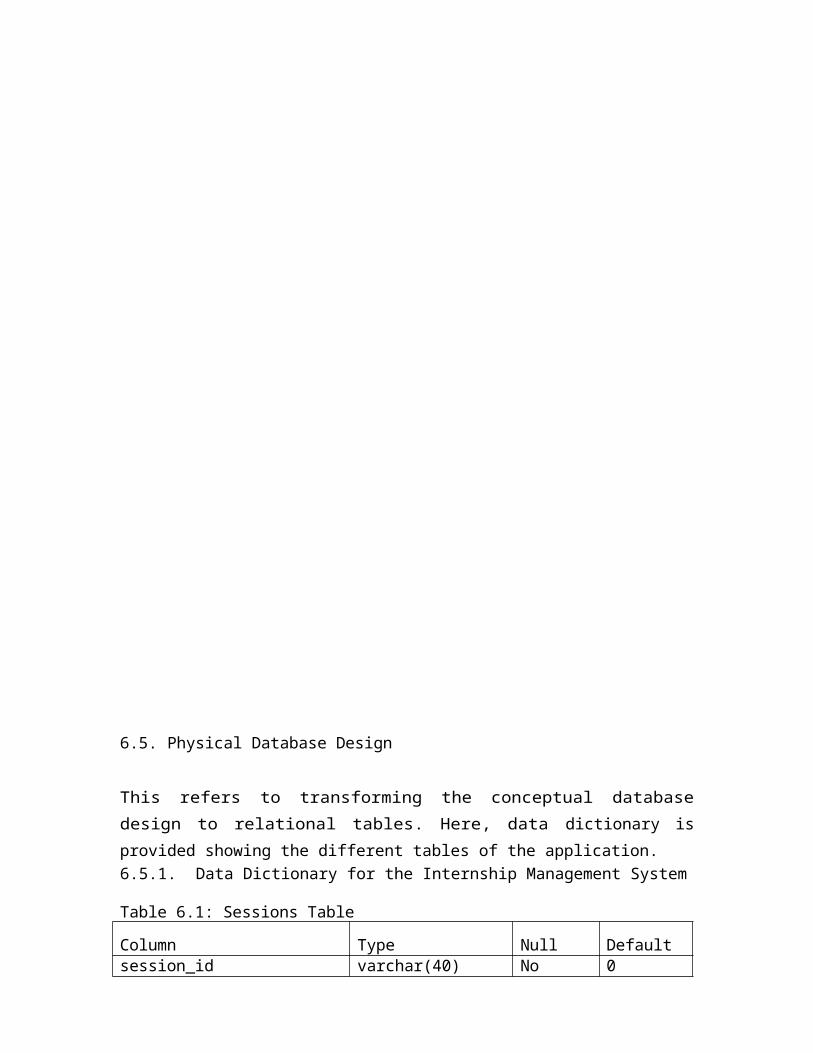
Figure 6.22: Architecture of the IMS
6.6.3. Rationale for Choosing the Client Server Architecture
A Client-Server Architecture consists of two types of components: clients and servers. A
server component perpetually listens for requests from client components. When a
request is received, the server processes the request, and then sends a response back to
the client. Below are the benefits of the Client-Server architecture:
a. Data Processing capability despite the location
We are in an era which undergoes a transformation from machine-centred systems to
user centred systems. Through a client/server system users can directly log into a system
despite of the location or technology of the processors.
b. Easy maintenance

Since client/server architecture is a distributed model representing dispersed
responsibilities among independent computers integrated across a network, it’s an
advantage in terms of maintenance. It’s easy to replace, repair, upgrade and relocate a
server while clients remain unaffected. This unawareness of change is called
encapsulation.
c. Security
Servers have better control access and resources to ensure that only authorized clients can
access or manipulate data and server-updates are administered effectively.
d. Flexibility
Client-Server architecture is flexible and hence allows new technology to be easily integrated.
e. Scalability
Client-Server architecture is scalable hence new features can be upgraded when needed.
f. Centralization
Access, resources and data security are controlled through the server.
g. Interoperability
All components (clients, network, and servers) work together.
Base on these benefits, the Client-Server architecture was chosen.
7. IMPLEMENTATION
Implementation in this context refers to programming. This is the phase that gave “birth” to
the system. The outputs from the analysis and design phase are used as input in this phase.
The main activity in this phase is programming.
7.1. Programming Languages and Tools Used
a. Languages
PHP (Hypertext Preprocessor) - Language used to program the logic of the system. Specifically, Code Igniter framework was used.
JavaScript and Jquery Library - was used to enhance the look and feel of the system. It was also used to improve usability.
Ajax - Was used for form submission and to improve usability.
HTML5 - Was used to design the graphical user interface.
CSS3 - Was used to design the graphical user interface.
Unified Modeling Language (UML) - Language used to develop a model for the system.
C Programming Language - Was used to count the number of distinct occurrences of languages in a text file and sort them out in alphabetical order for
used in a web form.
b. Software Packages and Tools Used
Planner (version 0.14.6) - Was used to develop the software development project plan for the
project.
Microsoft Visio (version 10) - Was used in the requirements phase to design basic
templates of how the system was going to look like.
Enterprise Architect (version 10.0) - Was used to draw the UML diagrams.
Komodo Edit, version 8.5.3 - Text editor used for coding the system.
JetBrainsPhpStorm 6.0.2 - IDE used for coding the system.
Google Chrome(Version32.0.1700.77), Firefox(version28), Safari and Internet
Explorer were the browsers used for testing the system.
MySQL Workbench - Was used to develop the Extended Entity Relationship (EER)
diagram.
XAMPP for Linux (Version 1.8.3-1) - It includes the following packages:
Web Server (Apache, version 2.4.4)
PHP, version 5.5.3
Database (MySQL, version 5.6.12)
Linux mint 17 (64 bits) and Windows 7 (64bits) were the platforms used for development.