Embed Size (px)
Citation preview
Business-Ready Configuration for Microsoft® Hyper-V™ R2 on Dell PowerEdge™ R-Series Servers with EqualLogic™ Storage
A Solutions Guide
August 2010
Dell │ Microsoft
Ryan Weldon and Lance Boley
Business Ready Configuration with Microsoft Hyper-V R2
Page ii
THIS WHITE PAPER IS FOR INFORMATIONAL PURPOSES ONLY, AND MAY CONTAIN TYPOGRAPHICAL
ERRORS AND TECHNICAL INACCURACIES. THE CONTENT IS PROVIDED AS IS, WITHOUT EXPRESS OR
IMPLIED WARRANTIES OF ANY KIND.
© 2010 Dell Inc. All rights reserved. Reproduction of this material in any manner whatsoever without
the express written permission of Dell Inc. is strictly forbidden. For more information, contact Dell.
Dell, the DELL logo, and the DELL badge, EqualLogic, PowerConnect, and PowerEdge are trademarks of
Dell Inc. Intel, Xeon and the Intel logo are trademarks or registered trademarks of Intel Corporation or
its affiliates in the US and other countries. Microsoft, Windows, Hyper-V, Windows Server, and Active
Directory are either trademarks or registered trademarks of Microsoft Corporation in the United States
and/or other countries.
3
Table of Contents Introduction ................................................................................................................ 6
1 Audience............................................................................................................... 6
2 Overview .............................................................................................................. 7
2.1 Reference Architectures ..................................................................................... 7
2.2 Design Principles .............................................................................................. 8
2.3 Base Solution Capabilities ................................................................................... 9
2.4 Advanced Solution Capabilities ........................................................................... 10
2.5 Required Components to Support Reference Architectures ......................................... 11
2.6 Reference Architecture Sizing ............................................................................ 12
2.7 Ordering ...................................................................................................... 13
2.7.1 What’s included? ......................................................................................... 14
2.8 Dell Global Services ......................................................................................... 14
3 Reference Architecture Hardware .............................................................................. 15
3.1 Virtualization Hosts – PowerEdge R710 .................................................................. 15
3.1.1 Networking – Hardware ................................................................................. 15
3.1.2 Networking – iSCSI traffic ............................................................................... 16
3.1.3 Networking ................................................................................................ 17
3.1.4 VLAN and Subnet Summary ............................................................................. 19
3.1.5 Power ....................................................................................................... 19
3.1.6 Storage ..................................................................................................... 19
3.1.7 Scalability ................................................................................................. 19
3.1.8 Customization ............................................................................................. 19
3.2 Virtualization Management – PowerEdge R610 ......................................................... 20
3.2.1 Networking ................................................................................................ 21
3.2.2 VLAN and Subnet Summary ............................................................................. 21
3.2.3 Power ....................................................................................................... 21
3.2.4 Storage ..................................................................................................... 21
3.2.5 Scalability ................................................................................................. 22
3.2.6 Customization ............................................................................................. 22
3.3 PowerConnect 8024F ....................................................................................... 22
3.3.1 Customizing Recommended Switch Configurations ................................................ 23
3.3.2 Jumbo Frames ............................................................................................ 24
3.3.3 ISL Configuration ......................................................................................... 24
Business Ready Configuration with Microsoft Hyper-V R2
4
3.3.4 Two switch configuration ............................................................................... 24
3.3.5 Four switch configuration .............................................................................. 26
3.3.6 Power ....................................................................................................... 28
3.3.7 Scalability ................................................................................................. 28
3.3.8 Customization ............................................................................................. 28
3.4 iSCSI Storage Array .......................................................................................... 29
3.4.1 RAID Configuration ....................................................................................... 29
3.4.2 LUN Configuration ........................................................................................ 29
3.4.3 Networking ................................................................................................ 29
4 Planning ............................................................................................................. 31
4.1 Data center support requirements ....................................................................... 31
4.2 Determining virtualization candidates .................................................................. 33
5 Deployment ......................................................................................................... 34
6 Additional Reading ................................................................................................. 37
7 Appendix A: Two Switch Sample Configuration ................................................................ 4
Business Ready Configuration with Microsoft Hyper-V R2
5
Table of Figures
Figure 1: Reference Architectures (Logical View)......................................................................................... 7 Figure 2: Reference Architectures with Required Components (Logical View) .......................................... 12 Figure 3: PowerEdge R710 Physical Network Connectivity ....................................................................... 16 Figure 4: Virtual VLAN Adapter Concept .................................................................................................... 17 Figure 5: Virtual VLAN Configuration .......................................................................................................... 18 Figure 6: PowerEdge R610 Networking ...................................................................................................... 21 Figure 7: PowerConnect 8024F Port Overview .......................................................................................... 22 Figure 8: PowerConnect 8024F Management Ports .................................................................................. 23 Figure 9: PowerConnect 8024F Port Mapping (Four switch configuration) ................................................ 25 Figure 10: Two Switch Configuration VLAN Overview ............................................................................... 25 Figure 11: Four Switch Configuration VLAN Overview ............................................................................... 26 Figure 12: Four Switch Configuration Server Connectivity ......................................................................... 27 Figure 13: PowerConnect 8024F Port Mapping (Four switch configuration) .............................................. 28 Figure 14: iSCSI Connectivity (Two Switch Configuration) ......................................................................... 30 Figure 15: iSCSI Connectivity (Four Switch Configuration) ........................................................................ 30
Business Ready Configuration with Microsoft Hyper-V R2
6
Introduction Business Ready Configurations for Virtualization are a family of reference architectures offered by Dell
designed to aid with the ordering, deployment, and maintenance of a virtualization infrastructure.
These architectures are designed to meet specific customer needs through the use of various server,
storage, and virtualization technologies available from Dell.
The reference architectures defined in this document are targeted at the large enterprise
virtualization needs, although others may also benefit from this architecture. These architectures
include Dell™ PowerEdge™ servers, Dell/Equallogic storage, and Microsoft® Hyper-V technology and are
built on a 10 Gigabit (10Gb) network architecture that utilizes Dell PowerConnect 8000 series switches.
Based on extensive design and engineering work, customers can quickly and confidently deploy this
proven engineering architecture into production environments, thereby helping to eliminate much of
the costly and time consuming trial and error work often encountered during complex deployments.
This guide includes information useful both before and after purchase of a Business Ready
Configuration. Prior to purchase, this information can aid with the sizing of the solution, licensing
selection, and preparation of the deployment environment for the solution. Post-purchase, this guide
can aid with the setup, configuration, and deployment of the solution. The architectures will help
customers achieve the full benefits of Microsoft Virtualization, Dell PowerEdge servers, and
Dell/EqualLogic storage in a 10Gb network environment.
1 Audience The intended audience for this white paper is IT administrators, IT managers, and channel partners
who are planning to deploy or resell Microsoft® Virtualization themselves or for their customers. This
white paper provides an overview of the recommended servers, storage, software, and services. It can
be used to plan, scope, and procure the required components to set up a virtualization infrastructure.
It is assumed that the reader has a basic understanding of server virtualization (Hyper-V preferred),
iSCSI storage, and networking concepts.
Business Ready Configuration with Microsoft Hyper-V R2
7
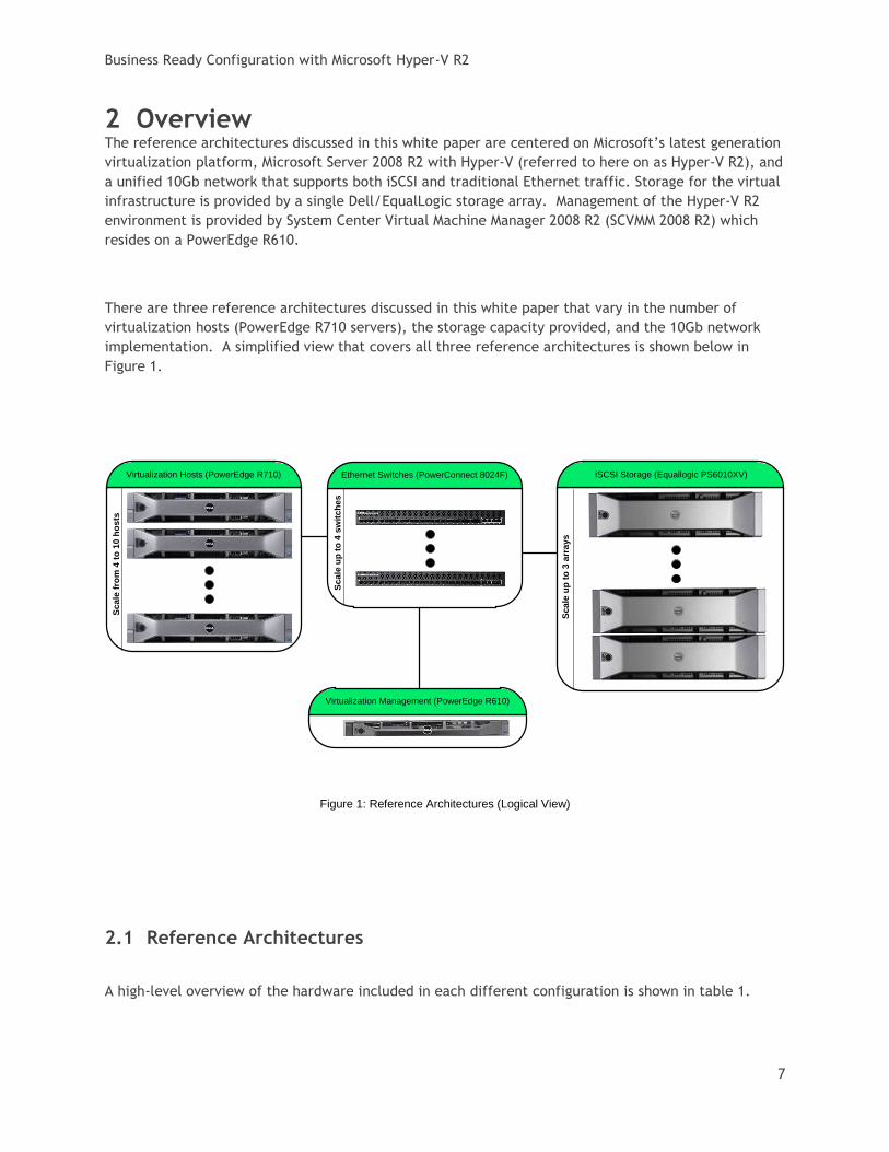
2 Overview The reference architectures discussed in this white paper are centered on Microsoft’s latest generation
virtualization platform, Microsoft Server 2008 R2 with Hyper-V (referred to here on as Hyper-V R2), and
a unified 10Gb network that supports both iSCSI and traditional Ethernet traffic. Storage for the virtual
infrastructure is provided by a single Dell/EqualLogic storage array. Management of the Hyper-V R2
environment is provided by System Center Virtual Machine Manager 2008 R2 (SCVMM 2008 R2) which
resides on a PowerEdge R610.
There are three reference architectures discussed in this white paper that vary in the number of
virtualization hosts (PowerEdge R710 servers), the storage capacity provided, and the 10Gb network
implementation. A simplified view that covers all three reference architectures is shown below in
Figure 1.
Figure 1: Reference Architectures (Logical View)
2.1 Reference Architectures
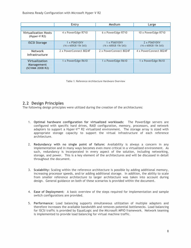
A high-level overview of the hardware included in each different configuration is shown in table 1.
Virtualization Hosts (PowerEdge R710) iSCSI Storage (Equallogic PS6010XV)
Virtualization Management (PowerEdge R610)
Sc
ale
fro
m 4
to
10
ho
sts
Sc
ale
up
to
3 a
rra
ys
Ethernet Switches (PowerConnect 8024F)
Sc
ale
up
to
4 s
wit
ch
es
Business Ready Configuration with Microsoft Hyper-V R2
8
Entry Medium Large
Virtualization Hosts (Hyper-V R2)
4 x PowerEdge R710 6 x PowerEdge R710 10 x PowerEdge R710
iSCSI Storage 1 x PS6010XV (16 x 600GB 15k SAS)
1 x PS6010XV (16 x 600GB 15k SAS)
2 x PS6010XV (16 x 600GB 15k SAS)
Network Infrastructure
2 x PowerConnect 8024F 2 x PowerConnect 8024F 4 x PowerConnect 8024F
Virtualization Management
(SCVMM 2008 R2)
1 x PowerEdge R610 1 x PowerEdge R610 1 x PowerEdge R610
Table 1: Reference Architecture Hardware Overview
2.2 Design Principles The following design principles were utilized during the creation of the architectures:
1. Optimal hardware configuration for virtualized workloads: The PowerEdge servers are configured with specific hard drives, RAID configuration, memory, processors, and network adapters to support a Hyper-V™ R2 virtualized environment. The storage array is sized with appropriate storage capacity to support the virtual infrastructure of each reference architecture.
2. Redundancy with no single point of failure: Availability is always a concern in any implementation and in many ways becomes even more critical in a virtualized environment. As such, redundancy is incorporated in every aspect of the solution, including networking, storage, and power. This is a key element of the architectures and will be discussed in detail throughout the document.
3. Scalability: Scaling within the reference architecture is possible by adding additional memory, increasing processor speeds, and/or adding additional storage. In addition, the ability to scale from smaller reference architecture to larger architecture was taken into account during design. General guidance on both of these scenarios is provided within the document.
4. Ease of Deployment: A basic overview of the steps required for implementation and sample switch configurations are provided.
5. Performance: Load balancing supports simultaneous utilization of multiple adapters and therefore increases the available bandwidth and removes potential bottlenecks. Load balancing for iSCSI traffic is provided by EqualLogic and the Microsoft MPIO framework. Network teaming is implemented to provide load balancing for virtual machine traffic.
Business Ready Configuration with Microsoft Hyper-V R2
9
6. Manageability: Virtualization management is accomplished with SCVMM 2008 R2 and provides a large number of advanced features over the base Hyper-V Manager interface that is provided in Hyper-V R2. The servers are configured with iDRAC 6 Enterprise controller to provide remote out-of-band management. The storage array and switches also support remote out-of-band management and are standard in each product.
7. Traffic Segregation and Prioritization: In a Hyper-V R2 environment that utilizes failover clustering with Dell best practices, there are a minimum of three unique types of traffic. With the unified fabric, iSCSI traffic is also on the same set of switches. To keep the traffic separated, VLANs are utilized in the reference architecture. Priority is given to critical traffic types (such as iSCSI) to provide distinct quality of service (QoS) levels on the unified network.
8. Integration into an existing data center: The architectures assume that there are existing services provided and either an existing 10Gb or 1Gb network. The minimum services required to support the architectures are DNS and Active Directory. In addition, it is assumed that there is network infrastructure (either 1Gb or 10/100Mb) in place to support the out-of-band hardware management network. Although the reference architectures implements VLANs, it is not a requirement that the existing data center infrastructure support this capability.
2.3 Base Solution Capabilities
With each of the reference architectures, the following capabilities are provided.
Virtual Machine High Availability: With the PowerEdge R710s being in a Microsoft Failover Cluster together, the virtual machines on these systems can be made “Highly Available” virtual machines. In the event that one of the R710 servers fails, the virtual machines that resided on that system can be restarted on another R710 server in the cluster without administrator intervention.
Virtual Machine Live Migration: An administrator can live migrate a virtual machine from one R710 server to another R710 to balance workload or prior to performing proactive maintenance. Live migration can be performed without administrator interaction when SCVMM 2008 R2 is integrated with System Center Operations Manager (see Section 3.4, Advanced Solution Capabilities).
Support for Cluster Share Volumes (CSV): A CSV provides the capability to host multiple virtual machines on a single volume and migrate those virtual machines independently amongst the R710 servers in the cluster. In addition, each R710 can simultaneously read and write directly (using its 10Gb iSCSI adapters) to the volume on the storage array.
Hot addition/removal of virtual machine storage: Storage can be dynamically allocated to a virtual machine while the virtual machine is running. If the guest operating system (guest OS) supports hot plug of storage devices, then capacity can be added or removed without restarting the guest OS.
Business Ready Configuration with Microsoft Hyper-V R2
10
Template-based virtual machine provisioning: Virtual machine templates can be created and stored in the SCVMM 2008 R2 library. These templates allow administrators to rapidly deploy standard virtual machines and support image generalization tools such as sysprep.
Workload Migration to Hyper-V R2: SCVMM 2008 R2 supports migration from physical servers to Hyper-V virtual machines and from ESX virtual machines to Hyper-V virtual machines. The guest operating system within those virtual machines must be a Microsoft operating system and specific versions are supported. For additional information refer to http://technet.microsoft.com/en-us/library/cc764277.aspx.
Self-service virtual machine provisioning: Administrators can delegate authority to other users or groups of users and allow them to create and utilize a predetermined set of virtual machines through a web interface. The web portal is provided by SCVMM 2008 R2 and supports integration with Active Directory.
Quick Storage Migration: This capability provided by SCVMM 2008 R2 allows administrators to move a virtual machine that resides on one storage device to another storage device. In our reference architectures, the primary use case exists if there is an additional Hyper-V R2 implementation in the data center. In this case, then individual virtual machines can be moved between the two instances. Note: Unlike virtual machine live migration, there can be application unavailability associated with the quick storage migration and should be planned for during this migration process.
2.4 Advanced Solution Capabilities There are numerous additions that can be made to enhance the base capabilities provided by the
reference architectures. We have highlighted a subset of those that provide easy integration and add
significant value.
Integration with Microsoft System Center Operations Manager (SCOM): Microsoft supports SCVMM and SCOM integration is supported through SCOM-based application monitoring of the SCVMM environment and through the Physical Resource Optimization (PRO) framework. The PRO framework allows administrators to load PRO-enabled management packs in SCOM that can create PRO Tips based on alerts received in SCOM. The PRO Tips are designed to remediate the underlying issue that initiated the alert and can be configured for automatic or manual implementation by administrators. To support this integration, the following components are required:
o SCVMM 2008 R2 Management Pack - This Microsoft management pack provides monitoring for the SCVMM server, library, self-service web portal, Hyper-V hosts, Virtual Server hosts, VMware ESX Server hosts, and their associated virtual machines. In addition, it enables third-party PRO packs (such as the Dell Server PRO Management Pack discussed below) to be loaded in SCOM. It also includes four Microsoft created PRO packs that provide PRO tips to optimize the performance of hosts and virtual machines based on CPU and memory thresholds. Of particular interest, there is a PRO tip that is generated when an individual Hyper-V host exceeds the CPU threshold and will live migrate a virtual machine or subset of virtual machines to another node in the cluster to load balance the virtual workload across the cluster.
Business Ready Configuration with Microsoft Hyper-V R2
11
The currently supported versions of SCOM at the time this document was published
are SCOM 2007 SP1 and 2007 R2. For additional details on this management pack,
refer to the SCVMM 2008 R2 Management Pack Guide available at
http://technet.microsoft.com/en-us/library/ee423731.aspx
o Dell Server PRO Management Pack v2.0 – This Dell created PRO pack integrates with Dell OpenManage to monitor events such as loss of power supply redundancy, exceed temperature threshold, server storage battery error, and internal disk failures. The PRO Tips generated support actions such as the live migration of all virtual machines off of the alerting host.
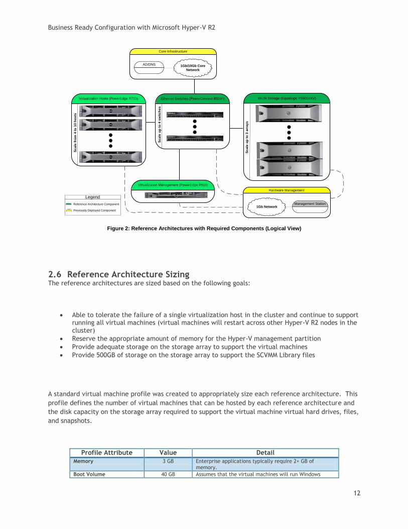
2.5 Required Components to Support Reference Architectures
To support any of the reference architectures, several components must either already be in place in
the data center or must be deployed simultaneously with the reference architecture. Active Directory
(AD) and Domain Name Services (DNS) are required to support the Hyper-V R2 failover cluster and
SCVMM 2008 R2. In addition, a 10/100Mb or 1Gb network infrastructure must be in place to support
out-of-band hardware management. A management station on the hardware management network
must be in place to support remote management. A simplified view of the reference architectures
along with the required components is shown in Figure 2.
Business Ready Configuration with Microsoft Hyper-V R2
12
Figure 2: Reference Architectures with Required Components (Logical View)
2.6 Reference Architecture Sizing The reference architectures are sized based on the following goals:
Able to tolerate the failure of a single virtualization host in the cluster and continue to support running all virtual machines (virtual machines will restart across other Hyper-V R2 nodes in the cluster)
Reserve the appropriate amount of memory for the Hyper-V management partition
Provide adequate storage on the storage array to support the virtual machines
Provide 500GB of storage on the storage array to support the SCVMM Library files
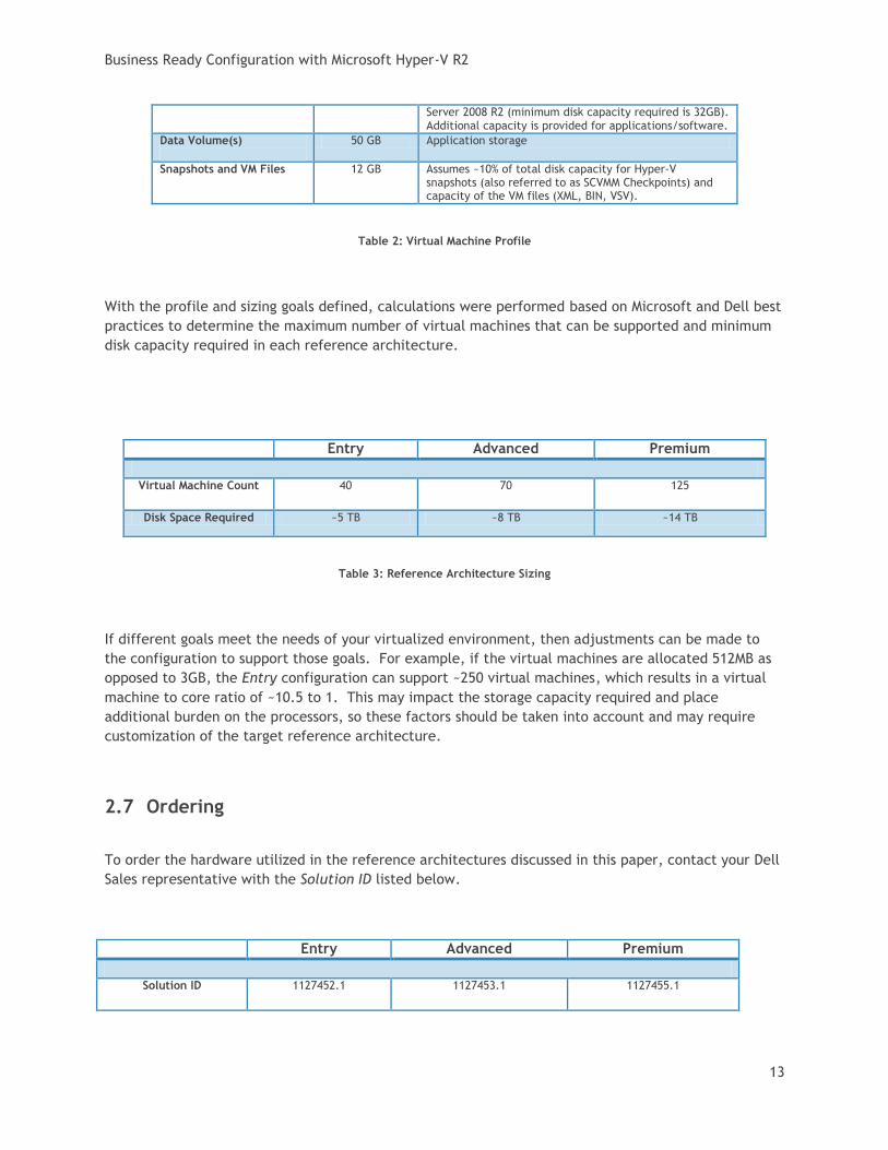
A standard virtual machine profile was created to appropriately size each reference architecture. This
profile defines the number of virtual machines that can be hosted by each reference architecture and
the disk capacity on the storage array required to support the virtual machine virtual hard drives, files,
and snapshots.
Profile Attribute Value Detail
Memory 3 GB Enterprise applications typically require 2+ GB of memory.
Boot Volume 40 GB Assumes that the virtual machines will run Windows
Virtualization Hosts (PowerEdge R710)
Virtualization Management (PowerEdge R610)
Sc
ale
fro
m 4
to
10
ho
sts
Core Infrastructure
AD/DNS 1Gb/10Gb Core
Network
Legend
Reference Architecture Component
Previously Deployed Component
Hardware Management
1Gb Network
Ethernet Switches (PowerConnect 8024F)
Sc
ale
up
to
4 s
wit
ch
es
Management Station
iSCSI Storage (Equallogic PS6010XV)
Sc
ale
up
to
3 a
rra
ys
Business Ready Configuration with Microsoft Hyper-V R2
13
Server 2008 R2 (minimum disk capacity required is 32GB). Additional capacity is provided for applications/software.
Data Volume(s)
50 GB Application storage
Snapshots and VM Files 12 GB Assumes ~10% of total disk capacity for Hyper-V snapshots (also referred to as SCVMM Checkpoints) and capacity of the VM files (XML, BIN, VSV).
Table 2: Virtual Machine Profile
With the profile and sizing goals defined, calculations were performed based on Microsoft and Dell best
practices to determine the maximum number of virtual machines that can be supported and minimum
disk capacity required in each reference architecture.
Entry Advanced Premium
Virtual Machine Count 40 70 125
Disk Space Required ~5 TB ~8 TB ~14 TB
Table 3: Reference Architecture Sizing
If different goals meet the needs of your virtualized environment, then adjustments can be made to
the configuration to support those goals. For example, if the virtual machines are allocated 512MB as
opposed to 3GB, the Entry configuration can support ~250 virtual machines, which results in a virtual
machine to core ratio of ~10.5 to 1. This may impact the storage capacity required and place
additional burden on the processors, so these factors should be taken into account and may require
customization of the target reference architecture.
2.7 Ordering
To order the hardware utilized in the reference architectures discussed in this paper, contact your Dell
Sales representative with the Solution ID listed below.
Entry Advanced Premium
Solution ID 1127452.1 1127453.1 1127455.1
Business Ready Configuration with Microsoft Hyper-V R2
14
Table 4: Reference Architecture Solution Identifiers
The servers and switches included in each reference architecture can also be directly ordered online
with a few clicks and is available at http://www.dell.com/virtualization/businessready.
2.7.1 What’s included? The solution ID’s provided in table 4 contain the servers and switches that are configured as defined in
Section 4, Reference Architecture Hardware. The 10Gb network cables required to interconnect the
reference architecture components (servers, switches, and storage) are also included.
The following list details additional components that may need to be removed from the order if your
datacenter already has them:
Rack
Power Distribution Units (PDU)
Uninterruptable Power Supply (UPS)
1Gb network cabling (CAT 5) for out-of-band hardware management
The requirements to support these additional components are defined in Section 5, Planning.
2.8 Dell Global Services
Dell Global Services helps customers find a suitable virtualization option to reduce total cost of
ownership, speed time to ROI, increase agility, and reclaim IT resources. Today’s financial environment
dictates that IT organizations reduce costs, while still providing ever-increasing infrastructure services.
Dell Global Services believes that by heavily leveraging server virtualization and increasing the rate of
adoption of this technology, you can accomplish this task.
Dell Global Services virtualization consultants work with customers to design and plan around the most
common bottlenecks in virtualization implementations. Our methodology, tools, and processes are
designed to speed up the implementation, ease migration scheduling, automate reporting, and provide
transparency to the entire process. Dell Global Services also has the ability to offer end-to-end
solutions with a single point-of-contact for hardware, software, services, and on-going support. Dell
Global Services are focused on IT infrastructure services excellence.
To engage Dell Global Services, see
http://www.dell.com/content/topics/global.aspx/services/adi/virtualization_new?c=us&cs=555&l=en
&s=biz.
15
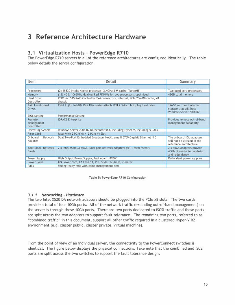
3 Reference Architecture Hardware
3.1 Virtualization Hosts – PowerEdge R710 The PowerEdge R710 servers in all of the reference architectures are configured identically. The table
below details the server configuration.
Item Detail Summary
Processors (2) E5530 Intel® Xeon® processor, 2.4GHz 8-M cache, TurboHT Two quad core processors
Memory (12) 4GB, 1066MHz dual-ranked RDIMMs for two processors, optimized 48GB total memory
Hard Drive Controller
PERC 6/i SAS RAID Controller 2x4 connectors, internal, PCIe 256-MB cache, x8 chassis
Raid Level/Hard Drives
Raid 1: (2) 146-GB 10-K RPM serial-attach SCSI 2.5-inch hot-plug hard drive 146GB mirrored internal storage that will host Windows Server 2008 R2
BIOS Setting Performance Setting
Remote Management Controller
iDRAC6 Enterprise Provides remote out-of-band management capability
Operating System Windows Server 2008 R2 Datacenter x64, including Hyper-V, including 5 CALs
Riser Card Riser with 2 PCIe x8 + 2 PCIe x4 Slot
Onboard Network Adapter
Dual Two-Port Embedded Broadcom NetXtreme II 5709 Gigabit Ethernet NIC The onboard 1Gb adapters will not be utilized in the reference architecture
Additional Network Cards
2 x Intel X520 DA 10GB, Dual port network adapters (SFP+ form factor) 2 x 10Gb adapters provide 40Gb of available bandwidth and redundancy
Power Supply High Output Power Supply, Redundant, 870W Redundant power supplies
Power Cord (2) Power cord, C13 to C14, PDU Style, 12 Amps, 2 meter
Rails Sliding ready rails with cable management arm
Table 5: PowerEdge R710 Configuration
3.1.1 Networking – Hardware The two Intel X520 DA network adapters should be plugged into the PCIe x8 slots. The two cards
provide a total of four 10Gb ports. All of the network traffic (excluding out-of-band management) on
the server is through these 10Gb ports. There are two ports dedicated to iSCSI traffic and those ports
are split across the two adapters to support fault tolerance. The remaining two ports, referred to as
“combined traffic” in this document, support all other traffic required in a clustered Hyper-V R2
environment (e.g. cluster public, cluster private, virtual machine).
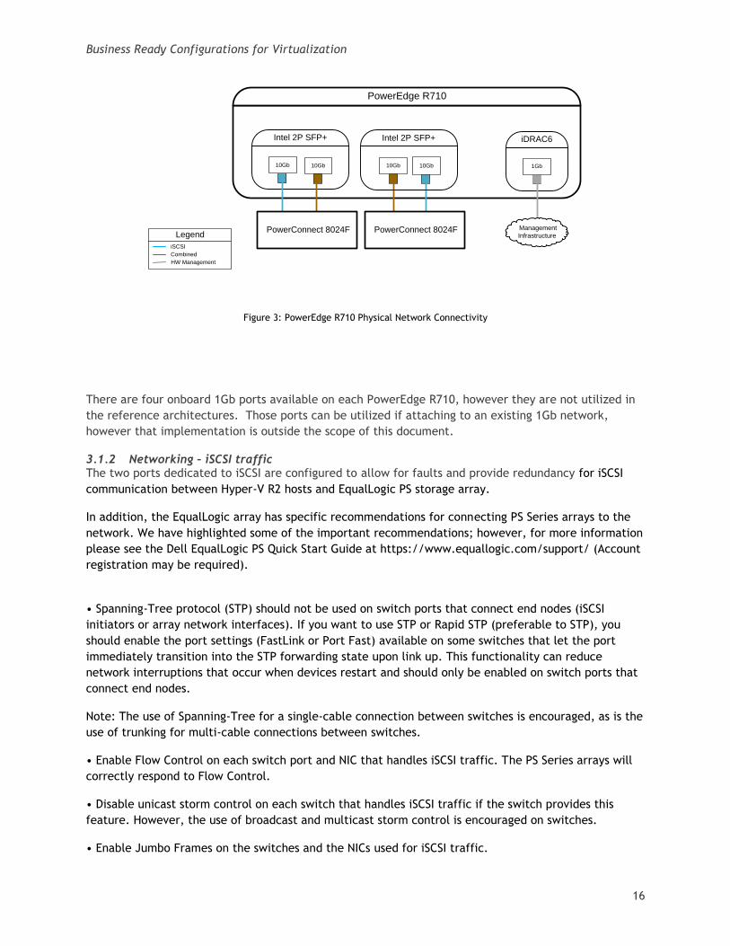
From the point of view of an individual server, the connectivity to the PowerConnect switches is
identical. The figure below displays the physical connections. Take note that the combined and iSCSI
ports are split across the two switches to support the fault tolerance design.
Business Ready Configurations for Virtualization
16
Figure 3: PowerEdge R710 Physical Network Connectivity
There are four onboard 1Gb ports available on each PowerEdge R710, however they are not utilized in
the reference architectures. Those ports can be utilized if attaching to an existing 1Gb network,
however that implementation is outside the scope of this document.
3.1.2 Networking – iSCSI traffic The two ports dedicated to iSCSI are configured to allow for faults and provide redundancy for iSCSI
communication between Hyper-V R2 hosts and EqualLogic PS storage array.
In addition, the EqualLogic array has specific recommendations for connecting PS Series arrays to the
network. We have highlighted some of the important recommendations; however, for more information
please see the Dell EqualLogic PS Quick Start Guide at https://www.equallogic.com/support/ (Account
registration may be required).
• Spanning-Tree protocol (STP) should not be used on switch ports that connect end nodes (iSCSI
initiators or array network interfaces). If you want to use STP or Rapid STP (preferable to STP), you
should enable the port settings (FastLink or Port Fast) available on some switches that let the port
immediately transition into the STP forwarding state upon link up. This functionality can reduce
network interruptions that occur when devices restart and should only be enabled on switch ports that
connect end nodes.
Note: The use of Spanning-Tree for a single-cable connection between switches is encouraged, as is the
use of trunking for multi-cable connections between switches.
• Enable Flow Control on each switch port and NIC that handles iSCSI traffic. The PS Series arrays will
correctly respond to Flow Control.
• Disable unicast storm control on each switch that handles iSCSI traffic if the switch provides this
feature. However, the use of broadcast and multicast storm control is encouraged on switches.
• Enable Jumbo Frames on the switches and the NICs used for iSCSI traffic.
PowerEdge R710
Intel 2P SFP+
10Gb 10Gb10Gb 10Gb
Intel 2P SFP+
Legend
iSCSI
Combined
HW Management
PowerConnect 8024F PowerConnect 8024F
iDRAC6
1Gb
Management
Infrastructure
Business Ready Configurations for Virtualization
17
• Disable iSCSI optimization on the PowerConnect 5424 switches used for iSCSI traffic.
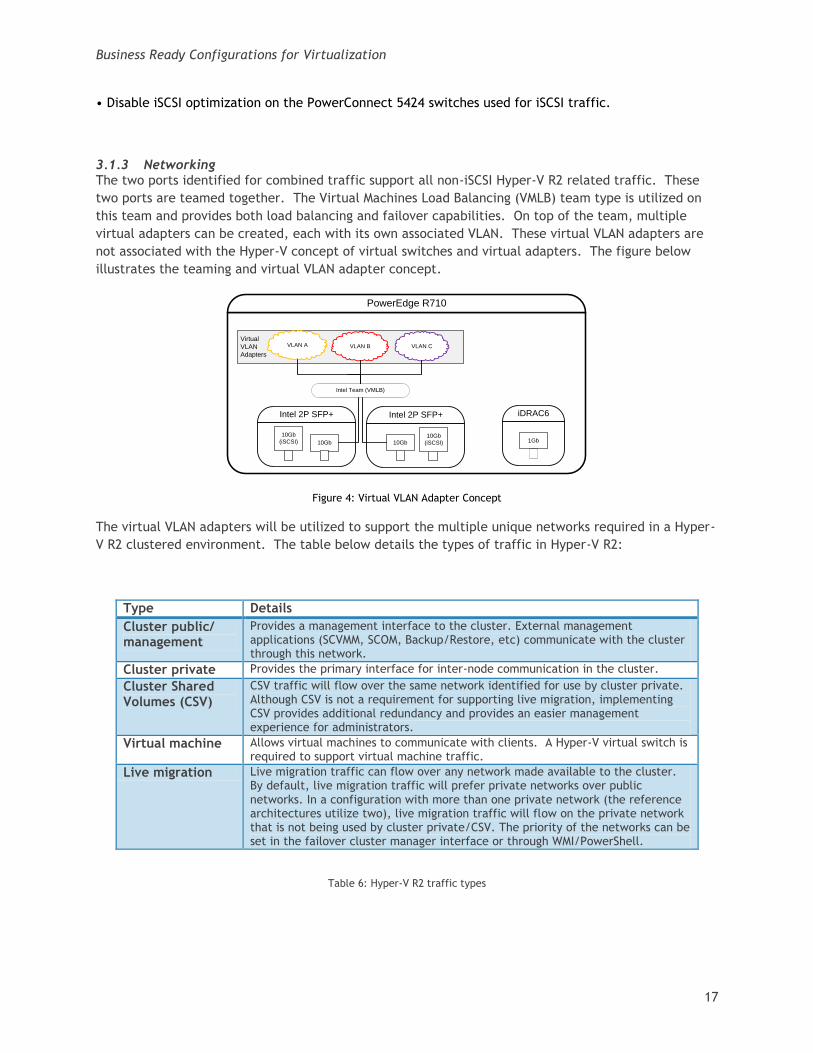
3.1.3 Networking The two ports identified for combined traffic support all non-iSCSI Hyper-V R2 related traffic. These
two ports are teamed together. The Virtual Machines Load Balancing (VMLB) team type is utilized on
this team and provides both load balancing and failover capabilities. On top of the team, multiple
virtual adapters can be created, each with its own associated VLAN. These virtual VLAN adapters are
not associated with the Hyper-V concept of virtual switches and virtual adapters. The figure below
illustrates the teaming and virtual VLAN adapter concept.
Figure 4: Virtual VLAN Adapter Concept
The virtual VLAN adapters will be utilized to support the multiple unique networks required in a Hyper-
V R2 clustered environment. The table below details the types of traffic in Hyper-V R2:
Type Details
Cluster public/ management
Provides a management interface to the cluster. External management applications (SCVMM, SCOM, Backup/Restore, etc) communicate with the cluster through this network.
Cluster private Provides the primary interface for inter-node communication in the cluster.
Cluster Shared Volumes (CSV)
CSV traffic will flow over the same network identified for use by cluster private. Although CSV is not a requirement for supporting live migration, implementing CSV provides additional redundancy and provides an easier management experience for administrators.
Virtual machine Allows virtual machines to communicate with clients. A Hyper-V virtual switch is required to support virtual machine traffic.
Live migration Live migration traffic can flow over any network made available to the cluster. By default, live migration traffic will prefer private networks over public networks. In a configuration with more than one private network (the reference architectures utilize two), live migration traffic will flow on the private network that is not being used by cluster private/CSV. The priority of the networks can be set in the failover cluster manager interface or through WMI/PowerShell.
Table 6: Hyper-V R2 traffic types
PowerEdge R710
Intel 2P SFP+
10Gb
10Gb
(iSCSI)
10Gb
(iSCSI) 10Gb
iDRAC6
1Gb
Intel 2P SFP+
Virtual
VLAN
Adapters
VLAN CVLAN B
Intel Team (VMLB)
VLAN A
Business Ready Configurations for Virtualization
18
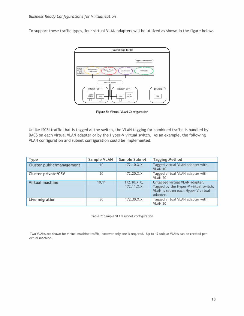
To support these traffic types, four virtual VLAN adapters will be utilized as shown in the figure below.
Figure 5: Virtual VLAN Configuration
Unlike iSCSI traffic that is tagged at the switch, the VLAN tagging for combined traffic is handled by
BACS on each virtual VLAN adapter or by the Hyper-V virtual switch. As an example, the following
VLAN configuration and subnet configuration could be implemented:
Type Sample VLAN Sample Subnet Tagging Method
Cluster public/management 10 172.10.X.X Tagged virtual VLAN adapter with VLAN 10
Cluster private/CSV 20 172.20.X.X Tagged virtual VLAN adapter with VLAN 20
Virtual machine 10,11 172.10.X.X, 172.11.X.X
Untagged virtual VLAN adapter. Tagged by the Hyper-V virtual switch; VLAN is set on each Hyper-V virtual adapter.
Live migration 30 172.30.X.X Tagged virtual VLAN adapter with VLAN 30
Table 7: Sample VLAN subnet configuration
Two VLANs are shown for virtual machine traffic, however only one is required. Up to 12 unique VLANs can be created per
virtual machine.
PowerEdge R710
Intel 2P SFP+
10Gb
10Gb
(iSCSI)
10Gb
(iSCSI) 10Gb
iDRAC6
1Gb
Intel 2P SFP+
Virtual
VLAN
Adapters
Live Migration VM TrafficCluster Private /
CSV
Intel VMLB team
Hyper-V Virtual Switch
Management /
Cluster Public
Business Ready Configurations for Virtualization
19
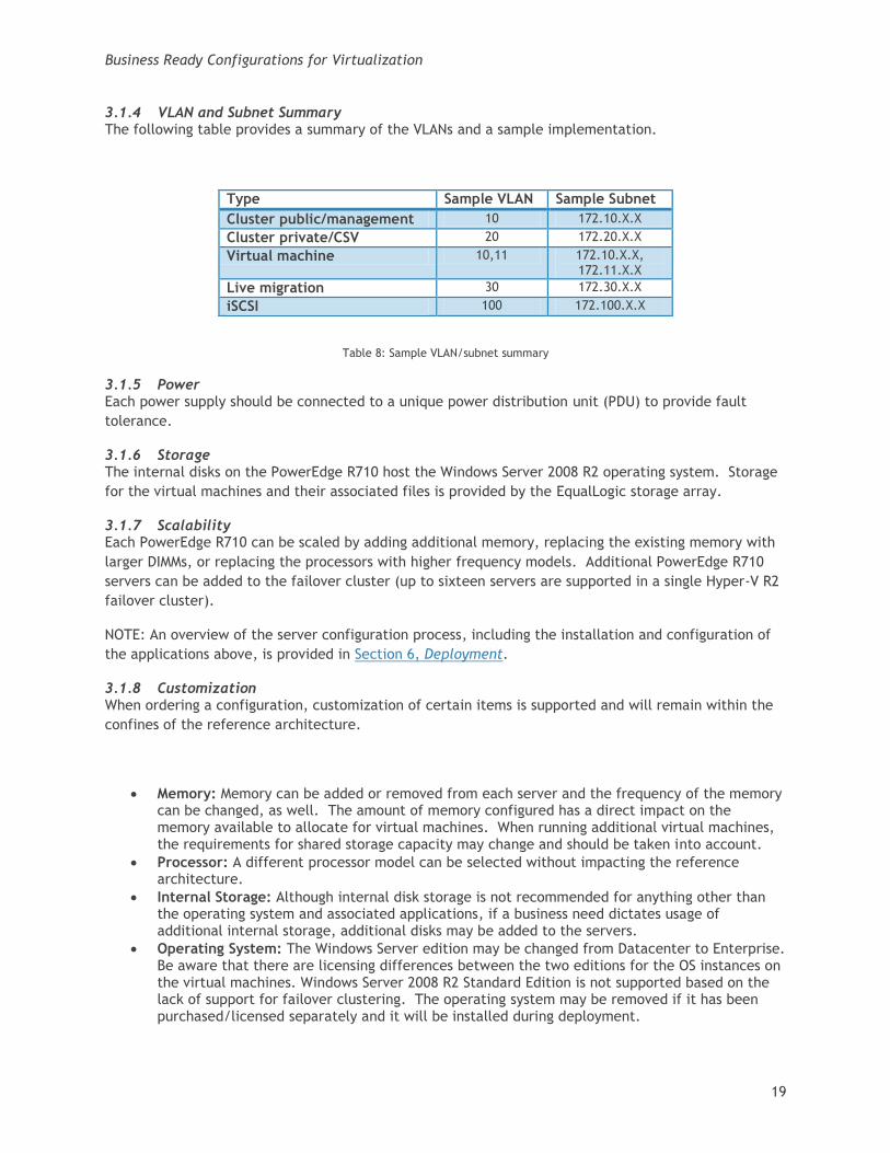
3.1.4 VLAN and Subnet Summary The following table provides a summary of the VLANs and a sample implementation.
Type Sample VLAN Sample Subnet
Cluster public/management 10 172.10.X.X
Cluster private/CSV 20 172.20.X.X
Virtual machine 10,11 172.10.X.X, 172.11.X.X
Live migration 30 172.30.X.X
iSCSI 100 172.100.X.X
Table 8: Sample VLAN/subnet summary
3.1.5 Power Each power supply should be connected to a unique power distribution unit (PDU) to provide fault
tolerance.
3.1.6 Storage The internal disks on the PowerEdge R710 host the Windows Server 2008 R2 operating system. Storage
for the virtual machines and their associated files is provided by the EqualLogic storage array.
3.1.7 Scalability Each PowerEdge R710 can be scaled by adding additional memory, replacing the existing memory with
larger DIMMs, or replacing the processors with higher frequency models. Additional PowerEdge R710
servers can be added to the failover cluster (up to sixteen servers are supported in a single Hyper-V R2
failover cluster).
NOTE: An overview of the server configuration process, including the installation and configuration of
the applications above, is provided in Section 6, Deployment.
3.1.8 Customization When ordering a configuration, customization of certain items is supported and will remain within the
confines of the reference architecture.
Memory: Memory can be added or removed from each server and the frequency of the memory can be changed, as well. The amount of memory configured has a direct impact on the memory available to allocate for virtual machines. When running additional virtual machines, the requirements for shared storage capacity may change and should be taken into account.
Processor: A different processor model can be selected without impacting the reference architecture.
Internal Storage: Although internal disk storage is not recommended for anything other than the operating system and associated applications, if a business need dictates usage of additional internal storage, additional disks may be added to the servers.
Operating System: The Windows Server edition may be changed from Datacenter to Enterprise. Be aware that there are licensing differences between the two editions for the OS instances on the virtual machines. Windows Server 2008 R2 Standard Edition is not supported based on the lack of support for failover clustering. The operating system may be removed if it has been purchased/licensed separately and it will be installed during deployment.
Business Ready Configurations for Virtualization
20
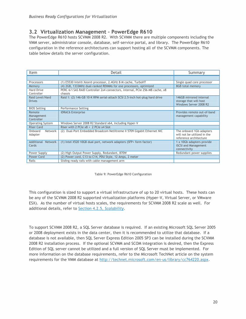
3.2 Virtualization Management – PowerEdge R610 The PowerEdge R610 hosts SCVMM 2008 R2. With SCVMM there are multiple components including the
VMM server, administrator console, database, self-service portal, and library. The PowerEdge R610
configuration in the reference architectures can support hosting all of the SCVMM components. The
table below details the server configuration.
Item Detail Summary
Processors (1) E5530 Intel® Xeon® processor, 2.4GHz 8-M cache, TurboHT Single quad core processor
Memory (4) 2GB, 1333MHz dual-ranked RDIMMs for one processors, optimized 8GB total memory
Hard Drive Controller
PERC 6/i SAS RAID Controller 2x4 connectors, internal, PCIe 256-MB cache, x8 chassis
Raid Level/Hard Drives
Raid 1: (2) 146-GB 10-K RPM serial-attach SCSI 2.5-inch hot-plug hard drive 146GB mirrored internal storage that will host Windows Server 2008 R2
BIOS Setting Performance Setting
Remote Management Controller
iDRAC6 Enterprise Provides remote out-of-band management capability
Operating System Windows Server 2008 R2 Standard x64, including Hyper-V
Riser Card Riser with 2 PCIe x8 + 2 PCIe x4 Slot
Onboard Network Adapter
(2) Dual-Port Embedded Broadcom NetXtreme II 5709 Gigabit Ethernet NIC The onboard 1Gb adapters will not be utilized in the reference architecture
Additional Network Cards
(1) Intel X520 10GB dual port, network adapters (SFP+ form factor) 1 x 10Gb adapters provide iSCSI and Management connectivity
Power Supply (2) High Output Power Supply, Redundant, 870W Redundant power supplies
Power Cord (2) Power cord, C13 to C14, PDU Style, 12 Amps, 2 meter
Rails Sliding ready rails with cable management arm
Table 9: PowerEdge R610 Configuration
This configuration is sized to support a virtual infrastructure of up to 20 virtual hosts. These hosts can
be any of the SCVMM 2008 R2 supported virtualization platforms (Hyper-V, Virtual Server, or VMware
ESX). As the number of virtual hosts scales, the requirements for SCVMM 2008 R2 scale as well. For
additional details, refer to Section 4.2.5, Scalability.
To support SCVMM 2008 R2, a SQL Server database is required. If an existing Microsoft SQL Server 2005
or 2008 deployment exists in the data center, then it is recommended to utilize that database. If a
database is not available, then SQL Server Express Edition 2005 SP3 can be installed during the SCVMM
2008 R2 installation process. If the optional SCVMM and SCOM integration is desired, then the Express
Edition of SQL server cannot be utilized and a full version of SQL Server must be implemented. For
more information on the database requirements, refer to the Microsoft TechNet article on the system
requirements for the VMM database at http://technet.microsoft.com/en-us/library/cc764220.aspx.
Business Ready Configurations for Virtualization
21
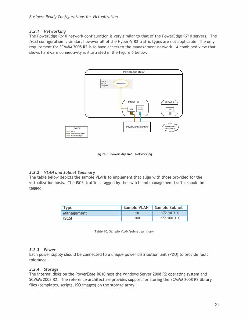
3.2.1 Networking The PowerEdge R610 network configuration is very similar to that of the PowerEdge R710 servers. The
iSCSI configuration is similar; however all of the Hyper-V R2 traffic types are not applicable. The only
requirement for SCVMM 2008 R2 is to have access to the management network. A combined view that
shows hardware connectivity is illustrated in the Figure 6 below.
Figure 6: PowerEdge R610 Networking
3.2.2 VLAN and Subnet Summary The table below depicts the sample VLANs to implement that align with those provided for the
virtualization hosts. The iSCSI traffic is tagged by the switch and management traffic should be
tagged.
Type Sample VLAN Sample Subnet
Management 10 172.10.X.X
iSCSI 100 172.100.X.X
Table 10: Sample VLAN/subnet summary
3.2.3 Power Each power supply should be connected to a unique power distribution unit (PDU) to provide fault
tolerance.
3.2.4 Storage The internal disks on the PowerEdge R610 host the Windows Server 2008 R2 operating system and
SCVMM 2008 R2. The reference architecture provides support for storing the SCVMM 2008 R2 library
files (templates, scripts, ISO images) on the storage array.
Virtual
VLAN
Adapters
PowerEdge R610
10Gb
(iSCSI)10Gb
iDRAC6
1Gb
Intel 2P SFP+
Management
Legend
iSCSI
Virtualization Mgmt
Hardware Mgmt
PowerConnect 8024F Management
Infrastructure
Business Ready Configurations for Virtualization
22
3.2.5 Scalability The PowerEdge R610 can be scaled by adding additional memory, replacing the existing memory with
larger DIMMs, adding an additional processor, or replacing the existing processor with a higher
frequency model. Scaling the PowerEdge R610 should be done in coordination with the scaling of the
overall virtualization environment that is going to be managed.
When scaling beyond 20 virtual hosts, the R610 in the default configuration defined above can be
utilized to support multiple SCVMM components, however it is recommended that the database be
moved to a separate system. For details on the system requirements for larger virtual infrastructures,
refer to the Microsoft TechNet article on VMM system requirements at
http://technet.microsoft.com/en-us/library/cc764328.aspx.
3.2.6 Customization Customization of the PowerEdge R610 should be done in accordance with the planned size of the
virtual infrastructure that will be supported. See Section 4.2.5, Scalability for more information. If
the datacenter has already deployed SCVMM 2008 R2, then the PowerEdge R610 can be removed from
the configuration.
3.3 PowerConnect 8024F The PowerConnect 8024F switches provide connectivity between the virtualization hosts, virtualization
management server, and the storage array. Each reference architecture utilizes the minimum number
of switches required to provide connectivity for the components, uplink to the existing switch
infrastructure, and redundancy in the event of a switch failure.
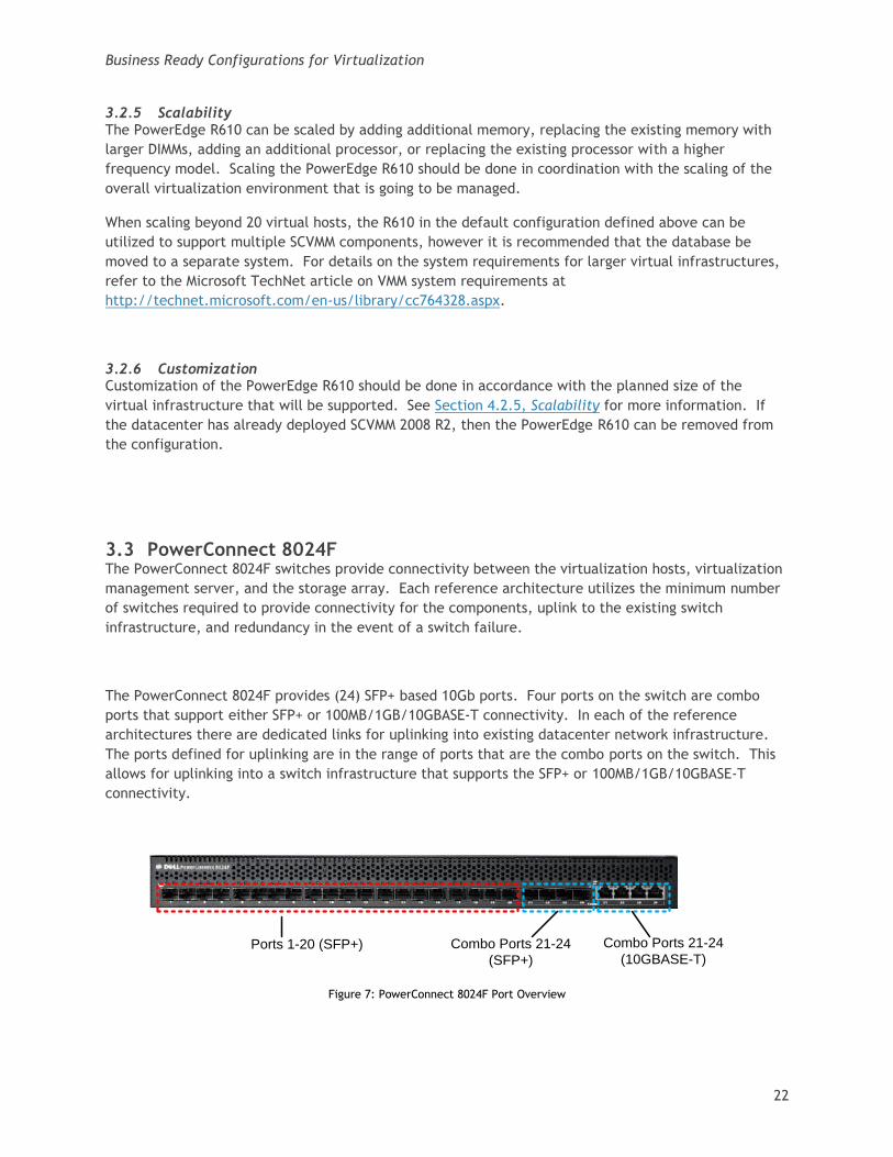
The PowerConnect 8024F provides (24) SFP+ based 10Gb ports. Four ports on the switch are combo
ports that support either SFP+ or 100MB/1GB/10GBASE-T connectivity. In each of the reference
architectures there are dedicated links for uplinking into existing datacenter network infrastructure.
The ports defined for uplinking are in the range of ports that are the combo ports on the switch. This
allows for uplinking into a switch infrastructure that supports the SFP+ or 100MB/1GB/10GBASE-T
connectivity.
Ports 1-20 (SFP+) Combo Ports 21-24
(SFP+)
Combo Ports 21-24
(10GBASE-T)
Figure 7: PowerConnect 8024F Port Overview
Business Ready Configurations for Virtualization
23
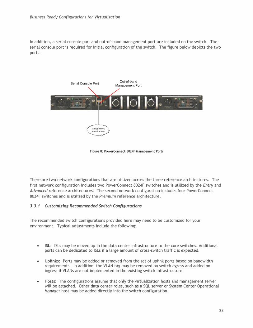
In addition, a serial console port and out-of-band management port are included on the switch. The
serial console port is required for initial configuration of the switch. The figure below depicts the two
ports.
Serial Console PortOut-of-band
Management Port
Management
Infrastructure
Figure 8: PowerConnect 8024F Management Ports
There are two network configurations that are utilized across the three reference architectures. The
first network configuration includes two PowerConnect 8024F switches and is utilized by the Entry and
Advanced reference architectures. The second network configuration includes four PowerConnect
8024F switches and is utilized by the Premium reference architecture.
3.3.1 Customizing Recommended Switch Configurations
The recommended switch configurations provided here may need to be customized for your
environment. Typical adjustments include the following:
ISL: ISLs may be moved up in the data center infrastructure to the core switches. Additional ports can be dedicated to ISLs if a large amount of cross-switch traffic is expected.
Uplinks: Ports may be added or removed from the set of uplink ports based on bandwidth requirements. In addition, the VLAN tag may be removed on switch egress and added on ingress if VLANs are not implemented in the existing switch infrastructure.
Hosts: The configurations assume that only the virtualization hosts and management server will be attached. Other data center roles, such as a SQL server or System Center Operational Manager host may be added directly into the switch configuration.
Business Ready Configurations for Virtualization
24
3.3.2 Jumbo Frames As discussed previously, the reference architectures utilize jumbo frames. To support jumbo frames,
each device in the path must support the larger MTU size. As such, the switches must be configured to
support this. The sample switch configuration provided in appendix A include the appropriate jumbo
frame settings.
3.3.3 ISL Configuration The ISLs configured in both the two switch and four switch configurations utilize a link aggregation
group (LAG) to combine the multiple ISL links into a single logical link. Without the LAG configuration,
a loop would be created, spanning tree protocol would break the loop, and only a single ISL link would
be utilized.
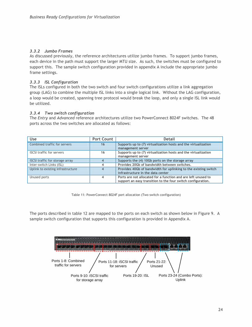
3.3.4 Two switch configuration The Entry and Advanced reference architectures utilize two PowerConnect 8024F switches. The 48
ports across the two switches are allocated as follows:
Use Port Count Detail
Combined traffic for servers 16 Supports up to (7) virtualization hosts and the virtualization management server
iSCSI traffic for servers 16 Supports up to (7) virtualization hosts and the virtualization management server
iSCSI traffic for storage array 4 Supports the (4) 10Gb ports on the storage array
Inter-switch Links (ISL) 4 Provides 20Gb of bandwidth between switches.
Uplink to existing infrastructure 4 Provides 40Gb of bandwidth for uplinking to the existing switch infrastructure in the data center
Unused ports 4 Ports are not allocated for a function and are left unused to support an easy transition to the four switch configuration.
Table 11: PowerConnect 8024F port allocation (Two switch configuration)
The ports described in table 12 are mapped to the ports on each switch as shown below in Figure 9. A
sample switch configuration that supports this configuration is provided in Appendix A.
Ports 1-8: Combined
traffic for servers
Ports 9-10: iSCSI traffic
for storage array
Ports 11-18: iSCSI traffic
for servers
Ports 19-20: ISL
Ports 21-22:
Unused
Ports 23-24 (Combo Ports):
Uplink
Business Ready Configurations for Virtualization
25
Figure 9: PowerConnect 8024F Port Mapping (Four switch configuration)
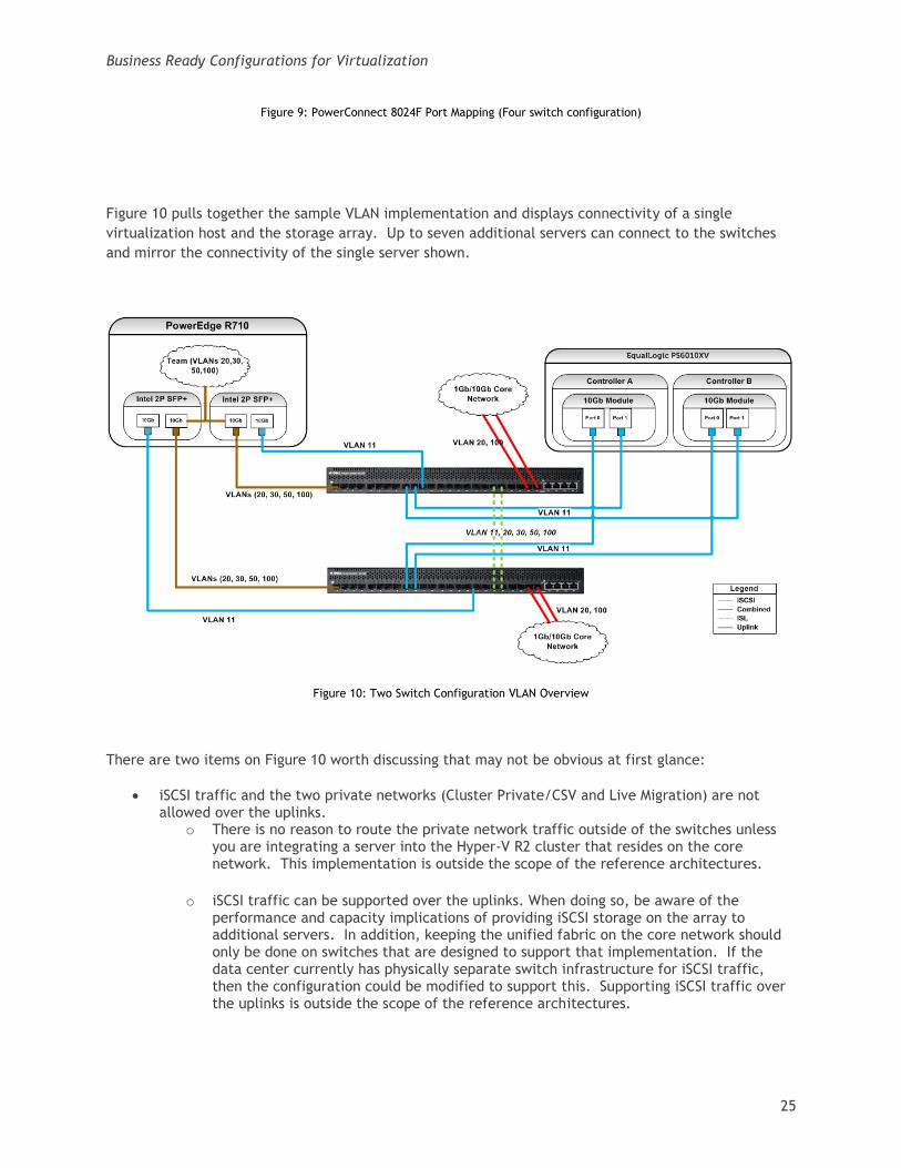
Figure 10 pulls together the sample VLAN implementation and displays connectivity of a single
virtualization host and the storage array. Up to seven additional servers can connect to the switches
and mirror the connectivity of the single server shown.
Figure 10: Two Switch Configuration VLAN Overview
There are two items on Figure 10 worth discussing that may not be obvious at first glance:
iSCSI traffic and the two private networks (Cluster Private/CSV and Live Migration) are not allowed over the uplinks.
o There is no reason to route the private network traffic outside of the switches unless you are integrating a server into the Hyper-V R2 cluster that resides on the core network. This implementation is outside the scope of the reference architectures.
o iSCSI traffic can be supported over the uplinks. When doing so, be aware of the performance and capacity implications of providing iSCSI storage on the array to additional servers. In addition, keeping the unified fabric on the core network should only be done on switches that are designed to support that implementation. If the data center currently has physically separate switch infrastructure for iSCSI traffic, then the configuration could be modified to support this. Supporting iSCSI traffic over the uplinks is outside the scope of the reference architectures.
Business Ready Configurations for Virtualization
26
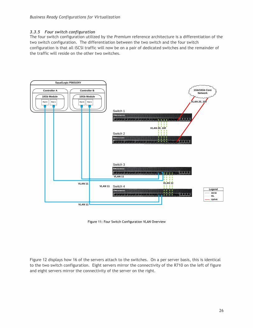
3.3.5 Four switch configuration The four switch configuration utilized by the Premium reference architecture is a differentiation of the
two switch configuration. The differentiation between the two switch and the four switch
configuration is that all iSCSI traffic will now be on a pair of dedicated switches and the remainder of
the traffic will reside on the other two switches.
Figure 11: Four Switch Configuration VLAN Overview
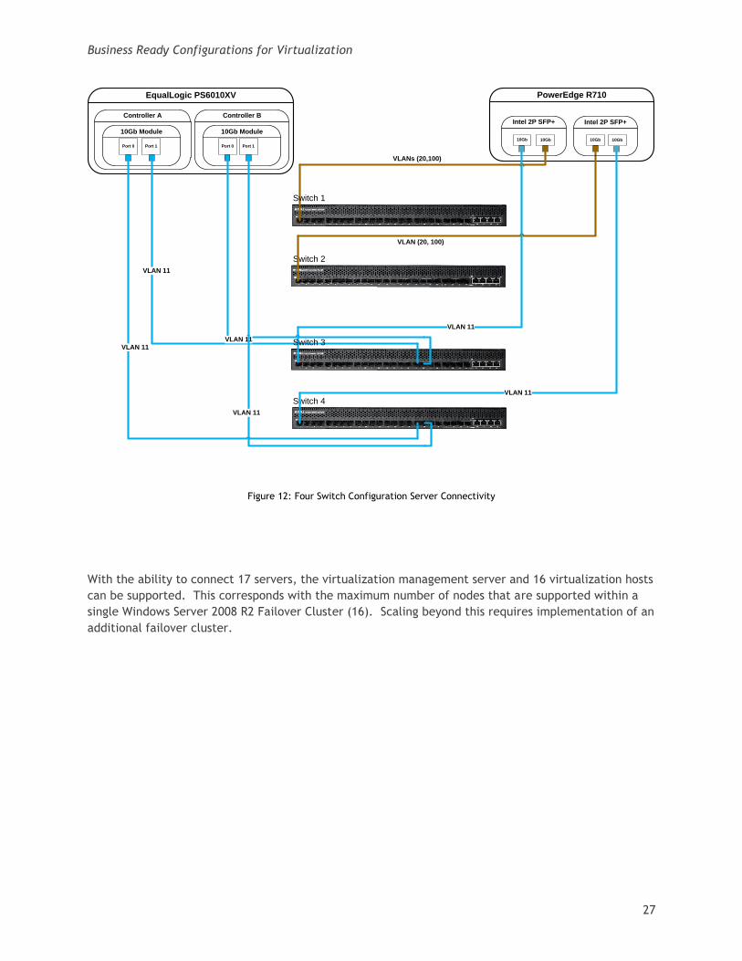
Figure 12 displays how 16 of the servers attach to the switches. On a per server basis, this is identical
to the two switch configuration. Eight servers mirror the connectivity of the R710 on the left of figure
and eight servers mirror the connectivity of the server on the right.
Switch 1
Switch 2
Switch 3
Switch 4
EqualLogic PS6010XV
Controller A
Port 0 Port 1 Port 0 Port 1
10Gb Module
Controller B
10Gb Module
VLAN 11VLAN 11
VLAN 11
VLAN 11
Legend
iSCSI
ISL
1Gb/10Gb Core
Network
VLAN 20, 100
Uplink
VLAN 20, 100
VLAN 11
Business Ready Configurations for Virtualization
27
Figure 12: Four Switch Configuration Server Connectivity
With the ability to connect 17 servers, the virtualization management server and 16 virtualization hosts
can be supported. This corresponds with the maximum number of nodes that are supported within a
single Windows Server 2008 R2 Failover Cluster (16). Scaling beyond this requires implementation of an
additional failover cluster.
Switch 2
Switch 4
EqualLogic PS6010XV
Controller A
Port 0 Port 1 Port 0 Port 1
10Gb Module
Controller B
10Gb Module
VLAN 11
VLAN 11
VLAN 11
VLAN 11
PowerEdge R710
Intel 2P SFP+
10Gb 10Gb10Gb
VLAN (20, 100)
10Gb
Intel 2P SFP+
VLAN 11
VLANs (20,100)
VLAN 11
Switch 1
Switch 3
Business Ready Configurations for Virtualization
28
Figure 13: PowerConnect 8024F Port Mapping (Four switch configuration)
3.3.6 Power The switch includes redundant power supplies. Each power supply should be connected to a unique
power distribution unit (PDU) to provide fault tolerance.
3.3.7 Scalability As mentioned previously, the two switch configuration was designed to support a simple upgrade path
to the four switch configuration. Only four cables will need to be moved from the existing two switch
configuration, eight cables added for ISL links, and the switch configurations will need to be updated.
Downtime should be planned for during the reconfiguration. Scaling below two or beyond four switches
is outside the scope of the reference architectures. Figure 13 depicts the four ports that need to be
moved (Port 9 and 23 on both switches) and the additional ISL links to cable.
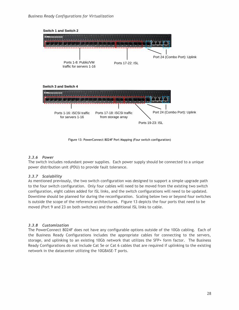
3.3.8 Customization The PowerConnect 8024F does not have any configurable options outside of the 10Gb cabling. Each of
the Business Ready Configurations includes the appropriate cables for connecting to the servers,
storage, and uplinking to an existing 10Gb network that utilizes the SFP+ form factor. The Business
Ready Configurations do not include Cat 5e or Cat 6 cables that are required if uplinking to the existing
network in the datacenter utilizing the 10GBASE-T ports.
Ports 1-16: iSCSI traffic
for servers 1-16
Ports 17-18: iSCSI traffic
from storage array
Ports 19-23: ISL
Port 24 (Combo Port): Uplink
Ports 1-8: Public/VM
traffic for servers 1-16Ports 17-22: ISL
Port 24 (Combo Port): Uplink
Switch 1 and Switch 2
Switch 3 and Switch 4
Business Ready Configurations for Virtualization
29
3.4 iSCSI Storage Array The EqualLogic storage array provides 10Gb iSCSI shared storage to support the Hyper-V R2 cluster,
virtual machines, and SCVMM 2008 R2 library files. The storage array consists of the following
components:
Main Chassis
Controllers
Power Supplies
3.4.1 RAID Configuration
The reference architectures assume that RAID 6 is implemented on each array. RAID 6 provides high
performance in various I/O patterns and data protection in the event of a disk failure. The reference
architecture also provides two global hot spares per physical array to support automatic rebuilding of
the RAID group in event of a disk failure.
Other RAID levels, such as RAID 5, RAID 50 and RAID10, can be implemented and may decrease or
increase the overall storage capacity based on the RAID level chosen.
3.4.2 LUN Configuration There is no single recommendation that can be provided that meets every application and/or
datacenter’s requirements. The rule is that the virtual machine’s I/O requirements are no different
than a physical machine. To determine what configuration is appropriate for your environment, you
must understand what the I/O requirements are going to be for each virtual machine or class of virtual
machines. There may be cases where multiple virtual machines and the application related data may
reside on a single LUN and other cases where the application data requires its own LUN.
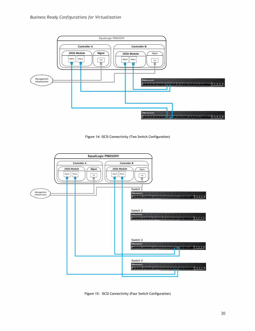
3.4.3 Networking The network connectivity implemented in the two switch configuration is shown in figure 19 and in the
four switch configuration in figure 20. For more details on the VLAN implementation refer to Section
4.3, PowerConnect 8024F.
Business Ready Configurations for Virtualization
30
Figure 14: iSCSI Connectivity (Two Switch Configuration)
Figure 15: iSCSI Connectivity (Four Switch Configuration)
Port 0 Port 1 Port 0 Port 1
10Gb Module 10Gb Module
EqualLogic PS6010XV
Controller A Controller B
Mgmt
1Gb
Management
Infrastructure
Mgmt
1Gb
Switch 2
Switch 4
EqualLogic PS6010XV
Controller A
Port 0 Port 1 Port 0 Port 1
10Gb Module
Controller B
10Gb Module
Switch 1
Switch 3
Mgmt
1Gb
Management
Infrastructure
Mgmt
1Gb
Business Ready Configurations for Virtualization
31
As mentioned previously, jumbo frames requires end-to-end configuration of the MTU size. As such,
the MTU of each 10Gb iSCSI port should be set to 9000 (maximum value supported by array).
4 Planning
4.1 Data center support requirements As we already discussed, there are certain components that must already be in place to support any of
the three reference architectures. The required and optional components are provided:
Active Directory: All Hyper-V R2 servers must be in the same AD domain
DNS: All Hyper-V R2 servers must use DNS for name resolution
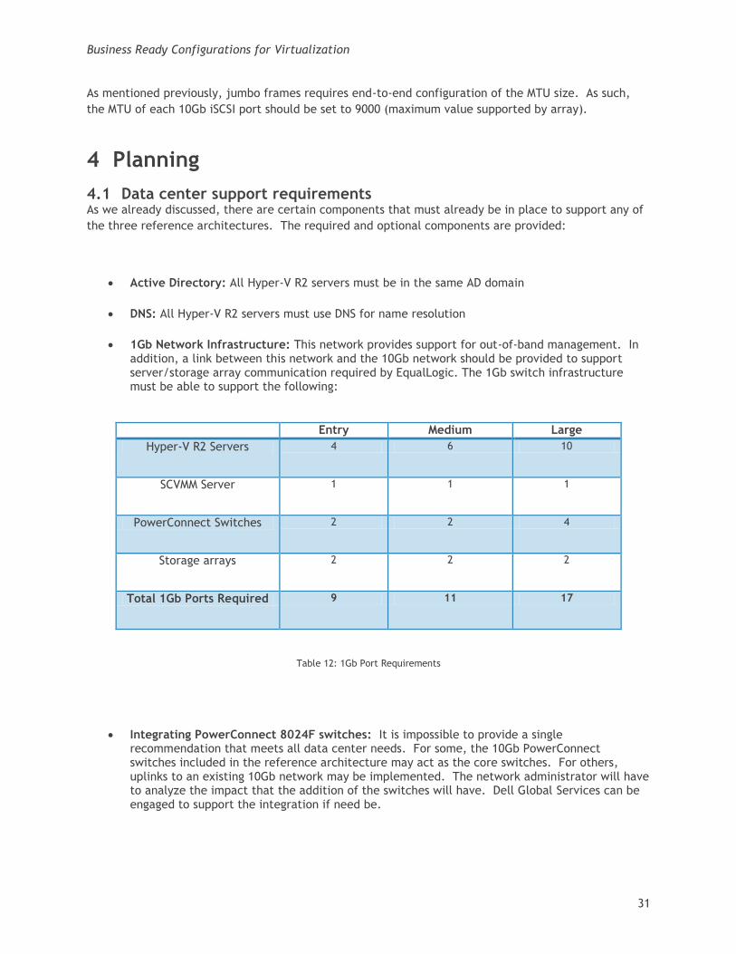
1Gb Network Infrastructure: This network provides support for out-of-band management. In addition, a link between this network and the 10Gb network should be provided to support server/storage array communication required by EqualLogic. The 1Gb switch infrastructure must be able to support the following:
Entry Medium Large
Hyper-V R2 Servers 4 6 10
SCVMM Server 1 1 1
PowerConnect Switches 2 2 4
Storage arrays 2 2 2
Total 1Gb Ports Required 9 11 17
Table 12: 1Gb Port Requirements
Integrating PowerConnect 8024F switches: It is impossible to provide a single recommendation that meets all data center needs. For some, the 10Gb PowerConnect switches included in the reference architecture may act as the core switches. For others, uplinks to an existing 10Gb network may be implemented. The network administrator will have to analyze the impact that the addition of the switches will have. Dell Global Services can be engaged to support the integration if need be.
Business Ready Configurations for Virtualization
32
Workstation: This system will be utilized to perform out-of-band management and configure the hardware devices. This system should run a Microsoft client (Windows XP or later) or server (Windows Server 2003 or later) operating system.
SQL Server (Optional): If integration between SCVMM and SCOM is desired, then either SQL Server 2005 or 2008 (Standard or Enterprise Editions) must be in place. For more information on the supported versions and required service packs, refer to the Microsoft TechNet article on VMM System Requirements available at http://technet.microsoft.com/en-us/library/cc764220.aspx.
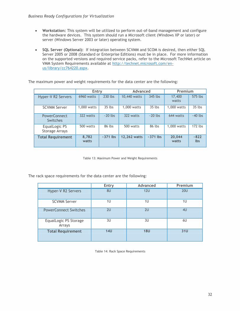
The maximum power and weight requirements for the data center are the following:
Entry Advanced Premium
Hyper-V R2 Servers 6960 watts 230 lbs 10,440 watts 345 lbs 17,400 watts
575 lbs
SCVMM Server 1,000 watts 35 lbs 1,000 watts 35 lbs 1,000 watts 35 lbs
PowerConnect Switches
322 watts ~20 lbs 322 watts ~20 lbs 644 watts ~40 lbs
EqualLogic PS Storage Arrays
500 watts 86 lbs 500 watts 86 lbs 1,000 watts 172 lbs
Total Requirement 8,782 watts
~371 lbs 12,262 watts ~371 lbs 20,044 watts
~822 lbs
Table 13: Maximum Power and Weight Requirements
The rack space requirements for the data center are the following:
Entry Advanced Premium
Hyper-V R2 Servers 8U 12U 20U
SCVMM Server 1U 1U 1U
PowerConnect Switches 2U 2U 4U
EqualLogic PS Storage Arrays
3U 3U 6U
Total Requirement 14U 18U 31U
Table 14: Rack Space Requirements
Business Ready Configurations for Virtualization
33
4.2 Determining virtualization candidates There are several methods available to determine potential virtualization candidates in the data
center:
Dell Global Services: http://content.dell.com/us/en/enterprise/d/services/it-consulting-virtualization-optimization-server-virtualization-assessment.aspx
Assessment Software: Software exists to analyze your data center and provide recommendations.
o Microsoft Assessment and Planning (MAP) Toolkit: MAP is a free kit that provides a hardware inventory, compatibility analysis, and a readiness report. For more information on MAP, refer to http://technet.microsoft.com/en-us/library/bb977556.aspx.
SCOM/SCVMM Reporting: When SCVMM and SCOM are integrated using the System Center VMM 2008 Management Pack, virtualization reports can be created. One of the reports, Virtualization Candidates, helps identify physical computers that may be good candidates for virtualization.
Business Ready Configurations for Virtualization
34
5 Deployment This section will aid in the deployment of the reference configuration. This an outline of the
procedures that need to be performed. For those familiar with the components in the reference
architecture, the outline may be sufficient to perform a successful deployment. However if this is not
the case, please refer to the product documentation for each component (links are provided in Section
8, Additional Reading).
1. Perform physical Configuration
Rack and cable the components of the reference architecture.
2. Configure PowerConnect 8024F switches
Perform initial configuration of switches (set the out-of-band management IP address).
Note: Management station to switch connection with a RJ-45 to DB-9 crossover cable
(included with switch) is required for initial configuration.
Connect to the Dell OpenManage Switch Administrator by browsing to the out-of-band management IP address and configure the switches.
3. Perform initial configuration of the storage array
Enable storage groups and pools on the array.
Configure the 10Gb network ports (Set IP address, enable jumbo frames).
Enable any optional array-based advanced features that were purchased (such as virtual provisioning).
4. Perform initial configuration of the Hyper-V R2 servers It is recommended to review the Microsoft® Windows Server® 2008 R2 With Hyper-V™ for
Dell™ PowerEdge™ Systems Important Information Guide available at
http://support.dell.com/support/edocs/software/win2008/WS08_R2/en/IIG_HyperV/IIG_HypV.
pdf. Among other things, this guide provides updates on the latest known issues and
resolutions.
On each Hyper-V R2 server perform the following:
Ensure Hardware-assisted virtualization (Intel-VT) is enabled in the BIOS.
Configure the iDRAC adapter (utility available during the boot process).
Install the latest supported version of the Dell Open Manage Server Administrator.
Enable the Hyper-V Role.
Configure the iSCSI adapters.
Configure network adapters.
Business Ready Configurations for Virtualization
35
o Set the static IP addresses adapters for cluster public, private, and live migration traffic.
o Configure a Hyper-V virtual switch on the untagged virtual VLAN adapter.
Note: The virtual switch must have the same name across all Hyper-V R2
servers in the cluster.
Enable the MPIO feature.
Start the iSCSI service.
Install the EqualLogic Host Integration Toolkit (HIT) software.
Configure the iSCSI initiator. o Connect to each 10Gb iSCSI port on the array (configure CHAP settings when
establishing each connection).
5. Perform initial configuration of the SCVMM 2008 R2 server
Ensure Hardware-assisted virtualization (Intel-VT) is enabled in the BIOS.
Configure the iDRAC adapter (utility available during the boot process).
Install the latest supported version of the Dell Open Manage Server Administrator.
Enable the Hyper-V Role (required to create virtual machines/templates and store them in the library).
Configure the iSCSI adapters. o Set the static IP addresses adapters.
Configure network adapters. o Set the static IP addresses adapters for cluster public, private, and live
migration traffic. o Configure a Hyper-V virtual switch on the untagged virtual VLAN adapter.
Note: The virtual switch must have the same name across all Hyper-V R2
servers in the cluster.
Enable MPIO feature.
Start the iSCSI service.
Install the EqualLogic Host Integration Toolkit (HIT) software. o Connect to each 10Gb iSCSI port on the array.
6. Provide Hyper-V R2 servers with storage (Quorum and VM storage).
Using Group Manager, perform the following: o Create a Storage Group.
Business Ready Configurations for Virtualization
36
o Create LUNs. o Add LUNs & Hyper-V R2 servers to storage group.
7. Provide SCVMM server with storage (VMM Library)
Using Group Manager, perform the following: o Create a Storage Group. o Create LUNs. o Add LUNs & Hyper-V R2 servers to storage group.
On the SCVMM server, perform the following: o Force a rescan via Disk Mgmt. o Format/Assign a drive letter.
8. Install SCVMM 2008 R2
On the SCVMM server, install SCVMM 2008 R2.
During installation either attach to an existing SQL server in the data center or allow the install procedure to install SQL Server Express Edition 2005 SP3.
Note: Do not add the Hyper-V R2 servers to the configuration yet.
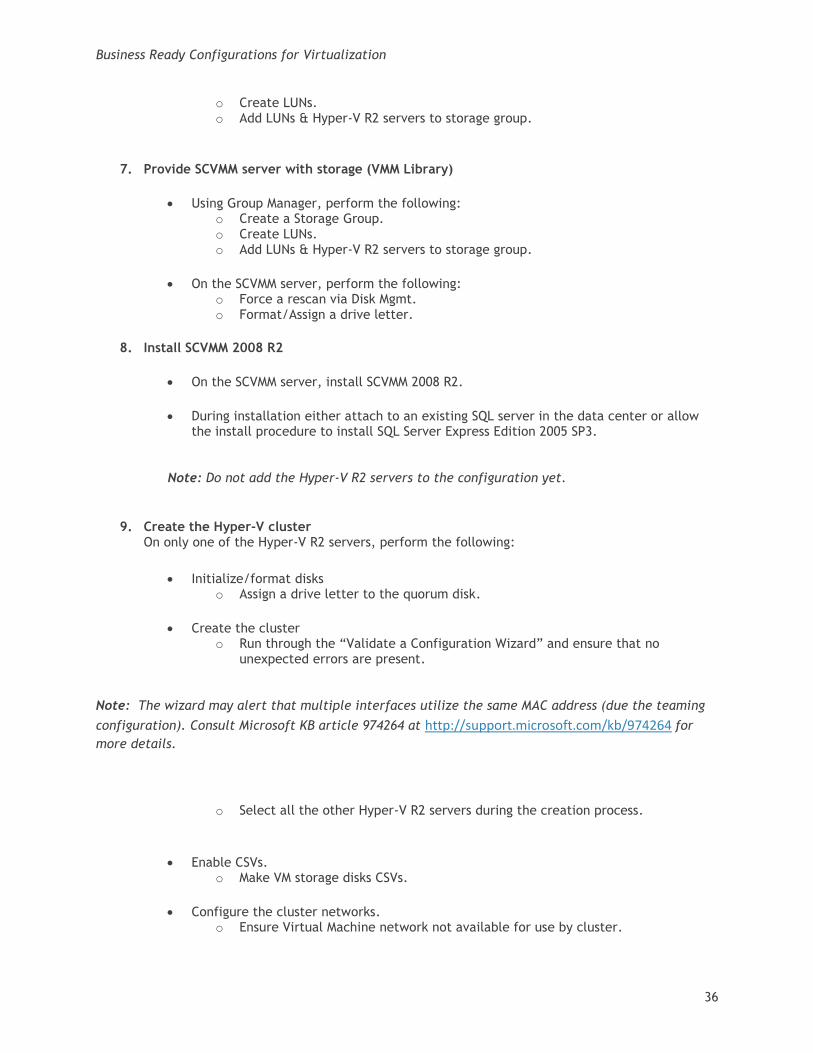
9. Create the Hyper-V cluster On only one of the Hyper-V R2 servers, perform the following:
Initialize/format disks o Assign a drive letter to the quorum disk.
Create the cluster o Run through the “Validate a Configuration Wizard” and ensure that no
unexpected errors are present.
Note: The wizard may alert that multiple interfaces utilize the same MAC address (due the teaming
configuration). Consult Microsoft KB article 974264 at http://support.microsoft.com/kb/974264 for
more details.
o Select all the other Hyper-V R2 servers during the creation process.
Enable CSVs. o Make VM storage disks CSVs.
Configure the cluster networks. o Ensure Virtual Machine network not available for use by cluster.
Business Ready Configurations for Virtualization
37
o Using the Failover Cluster Manager, set the priority of the networks for use by Live Migration (Live Migration (highest), Cluster Private/CSV, Cluster Public/Management).
o Configure the cluster network metrics on the private networks (Live Migration and Cluster Private/CSV).
10. Add Hyper-V R2 cluster to SCVMM configuration.
On the SCVMM server, add the Hyper-V R2 cluster to the SCVMM configuration.
11. Configure SCOM (Optional).
Add Hyper-V R2 servers and SCVMM server as managed systems.
Integrate SCVMM & SCOM. On the SCOM server, Install/Configure SCVMM 2008 R2 Management Pack.
On the SCOM server, Install/Configure Dell Server PRO Management Pack v2.0.
12. Deploy virtual machines. At this point, virtual machines are ready to be deployed. Either new guest OS instances can be
created or existing instances can be migrated to Hyper-V.
6 Additional Reading
Dell PowerEdge Server Documentation and Hardware/Software Updates
Visit support.dell.com, select “Drivers & Downloads”, enter a server service tag or select the
server model and operating system version (Adobe Flash is required).
Dell PowerConnect Switch Documentation and Firmware Updates
Visit support.dell.com, select “Drivers & Downloads”, enter a server service tag or select the
switch model and operating system version (Adobe Flash is required).
Dell Virtualization Documentation
Business Ready Configurations for Virtualization
2
Dell TechCenter Hyper-V R2 Blogs/Wiki Site
http://www.delltechcenter.com/page/Microsoft+Virtualization+-+Windows+2008+Hyper-V+R2
Microsoft® Windows Server® 2008 R2 With Hyper-V™ for Dell™ PowerEdge™ Systems Important
Information Guide
http://support.dell.com/support/edocs/software/win2008/WS08_R2/en/index.htm
Business Ready Configurations
http://www.dell.com/virtualization/businessready
Dell™ Server PRO Management Pack 2.0 For Microsoft® System Center Virtual Machine Manager
User’s Guide
Visit support.dell.com, search for “Dell Server PRO Management Pack”. The documentation is included
in the zip file that contains the management pack.
Microsoft® Hyper-V Documentation
Hyper-V Getting Started Guide
http://technet.microsoft.com/en-us/library/cc732470(WS.10).aspx
Microsoft® Management Software
Microsoft Server Management Suite Enterprise (SMSE)
http://www.microsoft.com/systemcenter/en/us/management-suites.aspx
Microsoft System Center Virtual Machine Manager
http://www.microsoft.com/systemcenter/virtualmachinemanager
Business Ready Configurations for Virtualization
3
Virtualization Solution Accelerators (MAP toolkit, IPD Guide)
http://www.microsoft.com/vsa
SCVMM 2008 R2 P2V and V2V Migration
http://technet.microsoft.com/en-us/library/cc764277.aspx
SCVMM 2008 R2 Management Pack Guide
http://technet.microsoft.com/en-us/library/ee423731.aspx
VMM Hardware Requirements
http://technet.microsoft.com/en-us/library/cc764328.aspx.
EqualLogic Storage and Software
User Programmable Documentation (Planning, Installation, Maintenance)
Business Ready Configurations for Virtualization
4
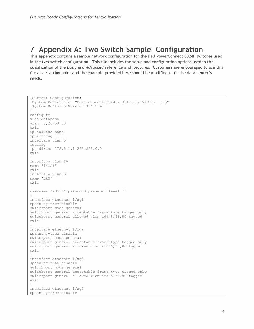
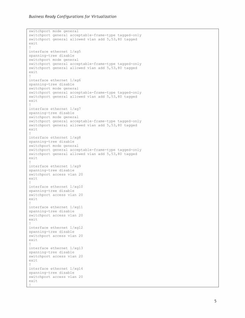
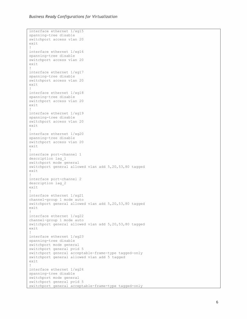
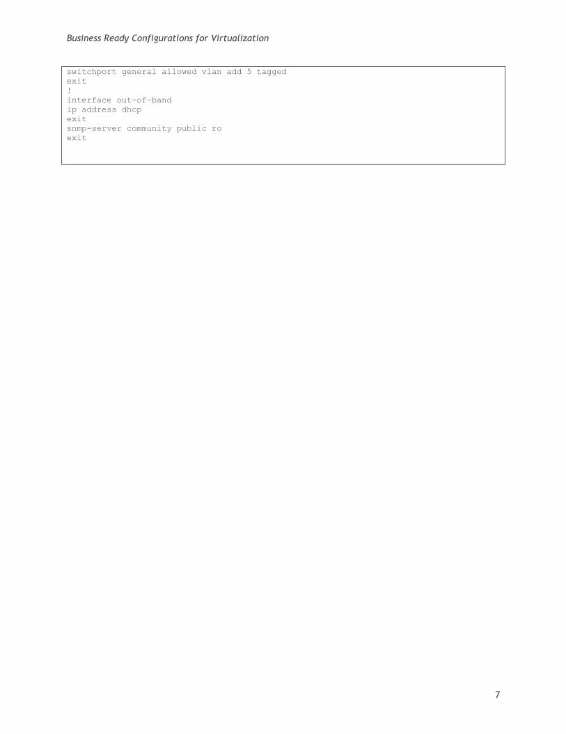
7 Appendix A: Two Switch Sample Configuration This appendix contains a sample network configuration for the Dell PowerConnect 8024F switches used
in the two switch configuration. This file includes the setup and configuration options used in the
qualification of the Basic and Advanced reference architectures. Customers are encouraged to use this
file as a starting point and the example provided here should be modified to fit the data center’s
needs.
!Current Configuration:
!System Description "Powerconnect 8024F, 3.1.1.9, VxWorks 6.5"
!System Software Version 3.1.1.9
!
configure
vlan database
vlan 5,20,53,80
exit
ip address none
ip routing
interface vlan 5
routing
ip address 172.5.1.1 255.255.0.0
exit
!
interface vlan 20
name "iSCSI"
exit
interface vlan 5
name "LAN"
exit
!
username "admin" password password level 15
!
interface ethernet 1/xg1
spanning-tree disable
switchport mode general
switchport general acceptable-frame-type tagged-only
switchport general allowed vlan add 5,53,80 tagged
exit
!
interface ethernet 1/xg2
spanning-tree disable
switchport mode general
switchport general acceptable-frame-type tagged-only
switchport general allowed vlan add 5,53,80 tagged
exit
!
interface ethernet 1/xg3
spanning-tree disable
switchport mode general
switchport general acceptable-frame-type tagged-only
switchport general allowed vlan add 5,53,80 tagged
exit
!
interface ethernet 1/xg4
spanning-tree disable
Business Ready Configurations for Virtualization
5
switchport mode general
switchport general acceptable-frame-type tagged-only
switchport general allowed vlan add 5,53,80 tagged
exit
!
interface ethernet 1/xg5
spanning-tree disable
switchport mode general
switchport general acceptable-frame-type tagged-only
switchport general allowed vlan add 5,53,80 tagged
exit
!
interface ethernet 1/xg6
spanning-tree disable
switchport mode general
switchport general acceptable-frame-type tagged-only
switchport general allowed vlan add 5,53,80 tagged
exit
!
interface ethernet 1/xg7
spanning-tree disable
switchport mode general
switchport general acceptable-frame-type tagged-only
switchport general allowed vlan add 5,53,80 tagged
exit
!
interface ethernet 1/xg8
spanning-tree disable
switchport mode general
switchport general acceptable-frame-type tagged-only
switchport general allowed vlan add 5,53,80 tagged
exit
!
interface ethernet 1/xg9
spanning-tree disable
switchport access vlan 20
exit
!
interface ethernet 1/xg10
spanning-tree disable
switchport access vlan 20
exit
!
interface ethernet 1/xg11
spanning-tree disable
switchport access vlan 20
exit
!
interface ethernet 1/xg12
spanning-tree disable
switchport access vlan 20
exit
!
interface ethernet 1/xg13
spanning-tree disable
switchport access vlan 20
exit
!
interface ethernet 1/xg14
spanning-tree disable
switchport access vlan 20
exit
!
Business Ready Configurations for Virtualization
6
interface ethernet 1/xg15
spanning-tree disable
switchport access vlan 20
exit
!
interface ethernet 1/xg16
spanning-tree disable
switchport access vlan 20
exit
!
interface ethernet 1/xg17
spanning-tree disable
switchport access vlan 20
exit
!
interface ethernet 1/xg18
spanning-tree disable
switchport access vlan 20
exit
!
interface ethernet 1/xg19
spanning-tree disable
switchport access vlan 20
exit
!
interface ethernet 1/xg20
spanning-tree disable
switchport access vlan 20
exit
!
interface port-channel 1
description lag_1
switchport mode general
switchport general allowed vlan add 5,20,53,80 tagged
exit
!
interface port-channel 2
description lag_2
exit
!
interface ethernet 1/xg21
channel-group 1 mode auto
switchport general allowed vlan add 5,20,53,80 tagged
exit
!
interface ethernet 1/xg22
channel-group 1 mode auto
switchport general allowed vlan add 5,20,53,80 tagged
exit
!
interface ethernet 1/xg23
spanning-tree disable
switchport mode general
switchport general pvid 5
switchport general acceptable-frame-type tagged-only
switchport general allowed vlan add 5 tagged
exit
!
interface ethernet 1/xg24
spanning-tree disable
switchport mode general
switchport general pvid 5
switchport general acceptable-frame-type tagged-only
Business Ready Configurations for Virtualization
7
switchport general allowed vlan add 5 tagged
exit
!
interface out-of-band
ip address dhcp
exit
snmp-server community public ro
exit