Embed Size (px)
Citation preview
Safety valves and upstream bursting discs in combination
The-Safety-Valve.com
CATALOG
Best AvailabilityBest Availability
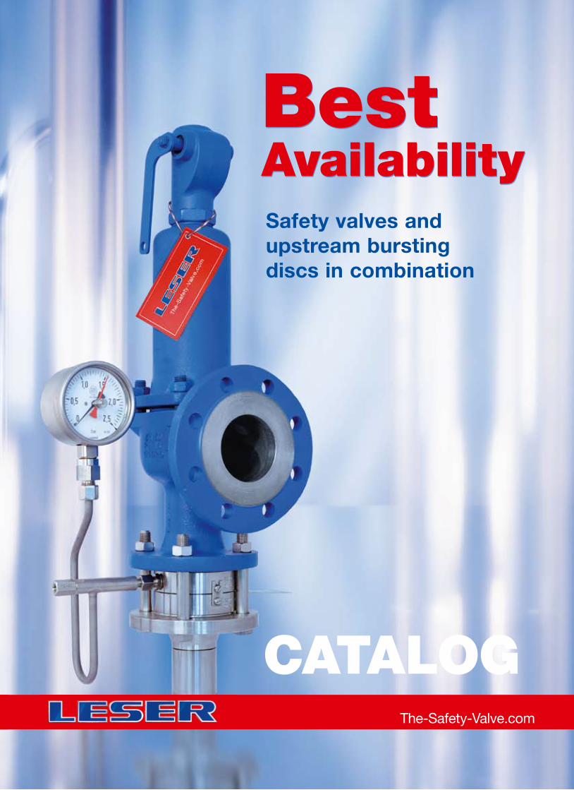
LESER Safety Valves for every industrial application
Product overviewProduct overview
API
Best Availability
Modulate Action
Best Availability
Clean Service
Critical Service
Compact Performance
Safety valves and bursting discs in combination
High Performance
H 2SO 4
HNO 3
NH 3
HCL
ContentsContents
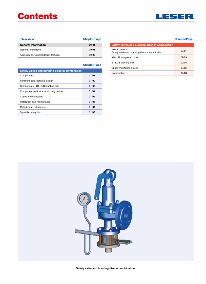
Safety valve and bursting disc in combination
Overview Chapter/Page
General Information 00/01
General Information 00/01
Applications, General design features 00/02
Chapter/Page
Safety valves and bursting discs in combination
How to order – Safety valves and bursting discs in combination
02/01
IG-KUB two-piece holder 02/03
BT-KUB bursting disc 02/04
Space monitoring device 02/05
Combination 02/06
Chapter/Page
Safety valves and bursting discs in combination
Components 01/01
Functions and technical design 01/02
Components – BT-KUB bursting disc 01/03
Components – Space monitoring device 01/04
Codes and standards 01/05
Installation and maintenance 01/06
Material characteristics 01/07
Signal bursting disc 01/08
General InformationGeneral Information
LWN 487.21-E00/01
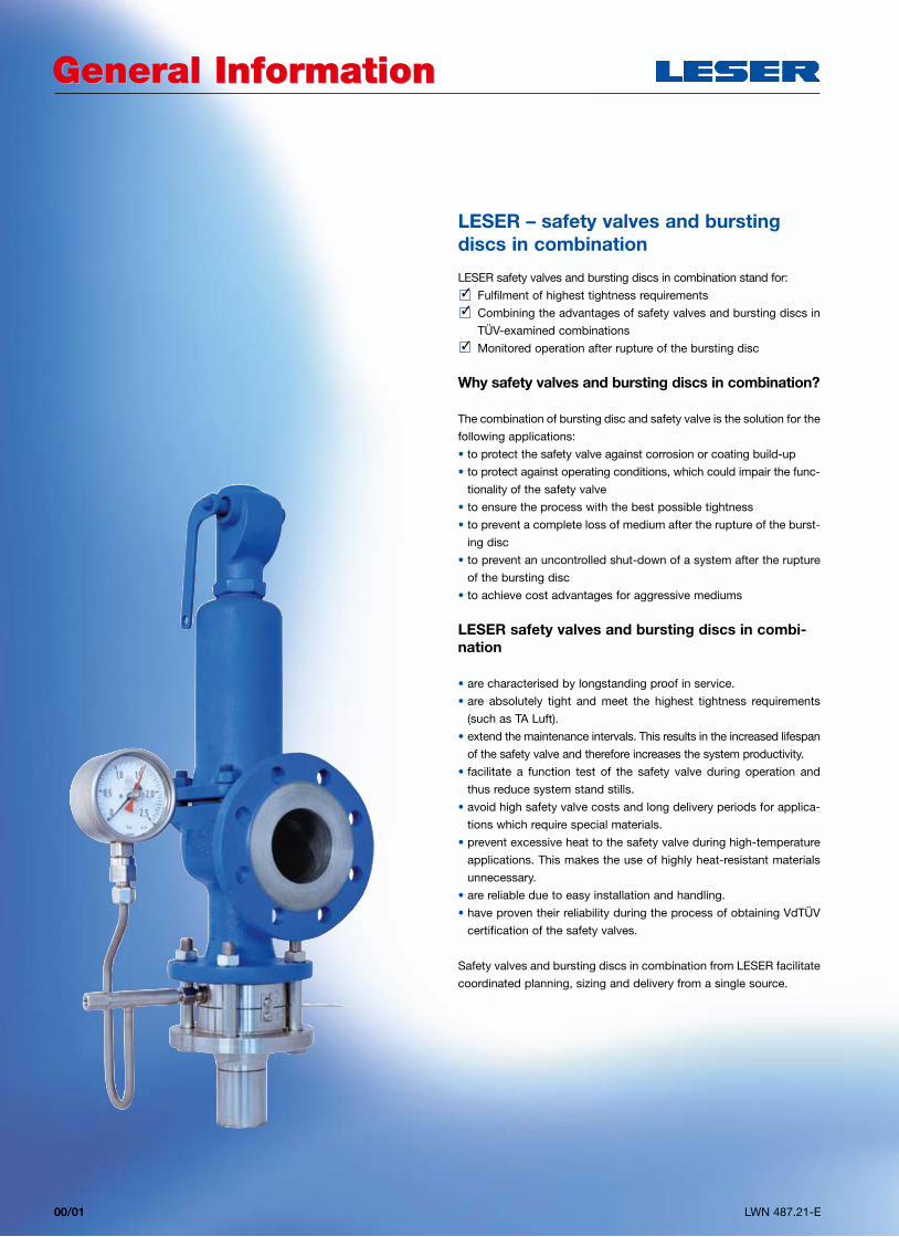
LESER – safety valves and bursting discs in combination
LESER safety valves and bursting discs in combination stand for:
3 Fulfilment of highest tightness requirements
3 Combining the advantages of safety valves and bursting discs in
TÜV-examined combinations
3 Monitored operation after rupture of the bursting disc
Why safety valves and bursting discs in combination?
The combination of bursting disc and safety valve is the solution for the
following applications:
• to protect the safety valve against corrosion or coating build-up
• to protect against operating conditions, which could impair the func-
tionality of the safety valve
• to ensure the process with the best possible tightness
• to prevent a complete loss of medium after the rupture of the burst-
ing disc
• to prevent an uncontrolled shut-down of a system after the rupture
of the bursting disc
• to achieve cost advantages for aggressive mediums
LESER safety valves and bursting discs in combi-nation
• are characterised by longstanding proof in service.
• are absolutely tight and meet the highest tightness requirements
(such as TA Luft).
• extend the maintenance intervals. This results in the increased lifespan
of the safety valve and therefore increases the system productivity.
• facilitate a function test of the safety valve during operation and
thus reduce system stand stills.
• avoid high safety valve costs and long delivery periods for applica-
tions which require special materials.
• prevent excessive heat to the safety valve during high-temperature
applications. This makes the use of highly heat-resistant materials
unnecessary.
• are reliable due to easy installation and handling.
• have proven their reliability during the process of obtaining VdTÜV
certification of the safety valves.
Safety valves and bursting discs in combination from LESER facilitate
coordinated planning, sizing and delivery from a single source.
General InformationGeneral Information
LWN 487.21-E 00/02
Applications
LESER safety valves and bursting discs in combina-tion are used for the following applications:
• for mediums which have a tendency to be sticky, such as
– marzipan
– bitumen
• to protect the safety valve against contamination, such as
– waste water
– coal slurry
• for highest tightness requirements, such as
– toxic and highly corrosive mediums (such as chlorine)
– expensive mediums (such as pharmaceutical products)
– vacuum applications
• when using special materials for cost advantages and shorter delivery
times, for example,
– the safety valve of stainless steel can be protected by the bursting
disc made of Hastelloy®
Design features
• Valve sizes from DN 25 to DN 400, 1" to 16"
• Nominal pressure ratings of PN 16 to PN 160, CL 150 to CL900
• Opening pressures of 0.6 bar to 200 bar / 8.7 psig to 2900 psig
• Bursting disc materials and temperature ranges:
• TA Luft conformal process validation offers the best possible tightness.
• High activation precision, for defined pressure releases.
• Operating pressures of up to 98% of the minimum set pressure of the
bursting disc are possible, and this provides an optimal utilisation of
the system.
• Performance, discharge number and opening characteristic of the
safety valve are not effected.
• Compliance to the 3% criterion – the bursting disc does not have to
be considered in the sizing.
Material 1.4404 Hastelloy® Inconel®
Temperature ranges
Min. [°C/°F]
-30 -22 -30 -22 -22 -30
Rembe® KUB bursting discs
Max. [°C/°F]
320 608 420 788 550 1022
Material Tantalum Titanium Monel®
Temperature ranges
Min. [°C/°F]
-22 -30 -30 -22 -30 -22
Rembe® KUB bursting discs
Max. [°C/°F]
230 446 150 302 400 752
LESER – safety valves and bursting discs in combination
Country Safety valve approvals Bursting disc approvals
Europe
– CE marking as per Pressure Equipment Directives 97/23/EC and
– EN ISO 4126-1
– CE marking as per Pressure Equipment Directives 97/23/EC and
– EN ISO 4126-2
USA
– UV stamp as per ASME Section VIII Division 1
– National Board certified capacities
– UD stamp as per ASME Section VIII Division 1
– National Board certified capacities
Germany
VdTÜV approval as per – AD 2000-Merkblatt A2 – EN ISO 4126-1– TÜV SV 100
VdTÜV approval as per – AD 2000-Merkblatt A2 – EN ISO 4126-2/ -6
Worldwide Use
The LESER safety valves and bursting discs in combination are tested
and approved in accordance with VdTÜV. Application of the combina-
tion is done according to
– EN ISO 4126-3
– AD 2000-Merkblatt A1
– ASME Sec. VIII Div. 1
LESER safety valves and bursting discs are accepted individually in
accordance with numerous rules and regulations. This ensures the
worldwide applicability of the combinations. Examples of this are:
LWN 487.21-E01/01
Safety valves and bursting discs in combinationSafety valves and bursting discs in combination
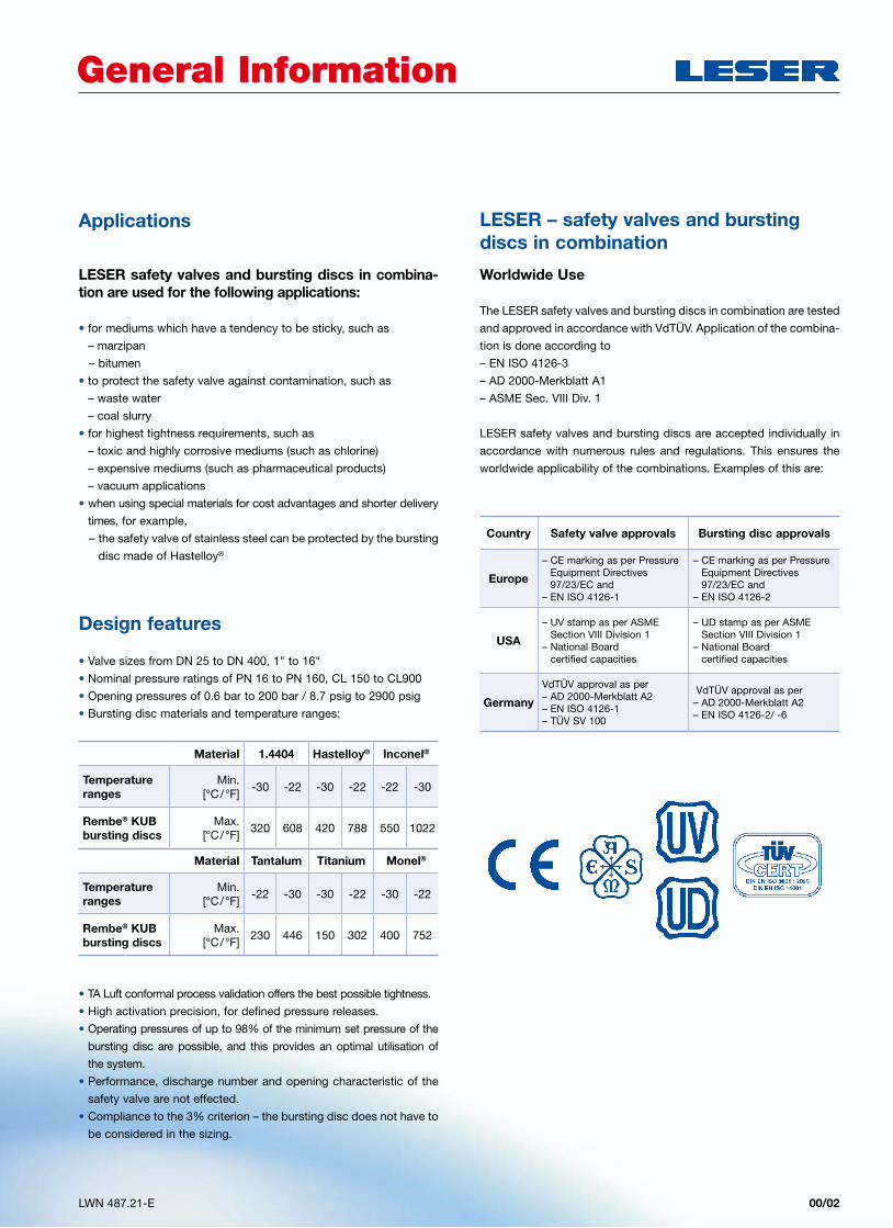
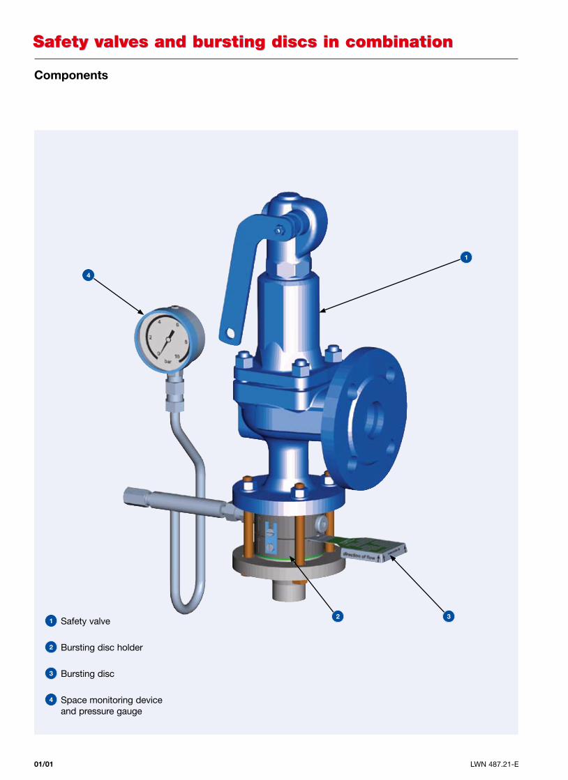
Components
1 Safety valve
2 Bursting disc holder
3 Bursting disc
4 Space monitoring device and pressure gauge
4
2
1
3
LWN 487.21-E 01/02
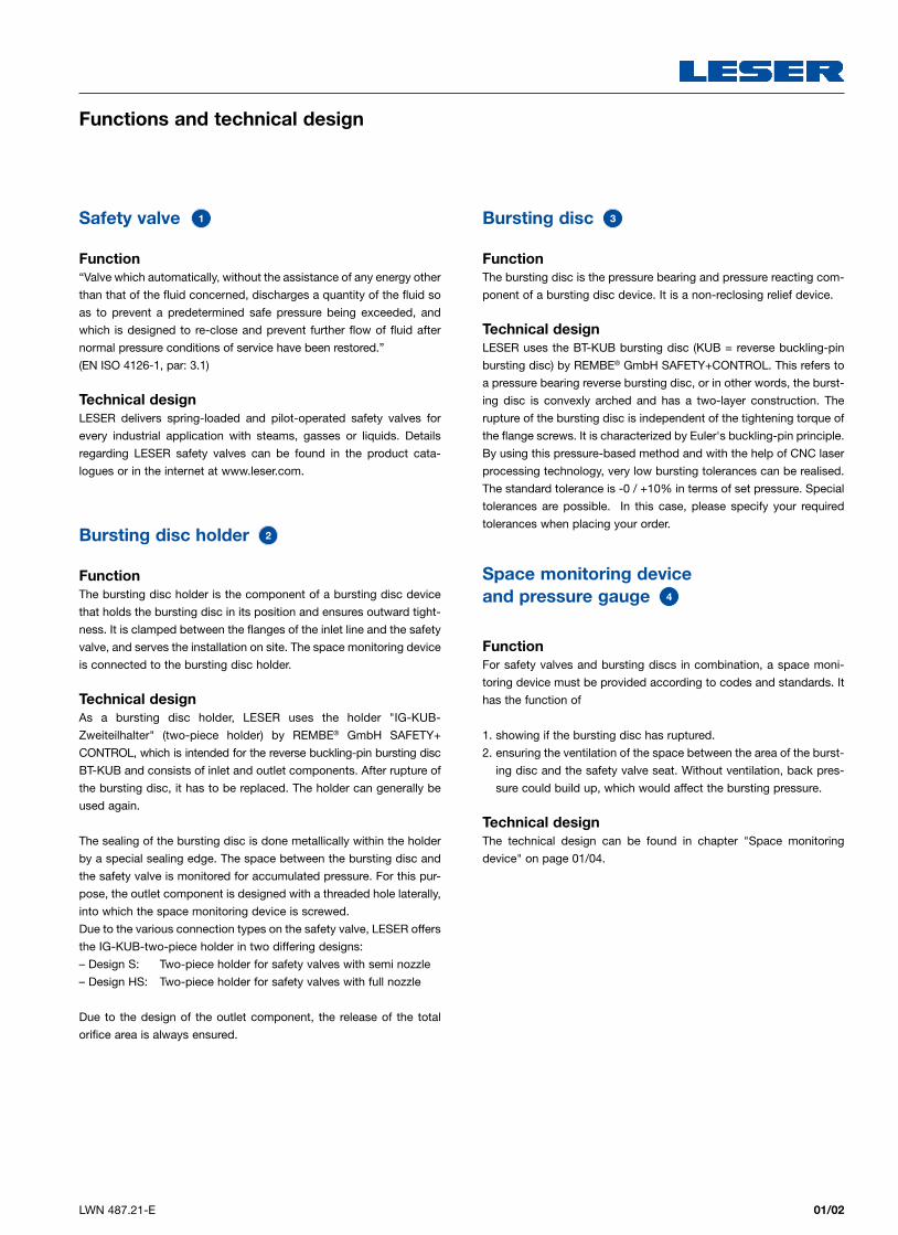
Safety valve 1
Function
“Valve which automatically, without the assistance of any energy other
than that of the fluid concerned, discharges a quantity of the fluid so
as to prevent a predetermined safe pressure being exceeded, and
which is designed to re-close and prevent further flow of fluid after
normal pressure conditions of service have been restored.”
(EN ISO 4126-1, par: 3.1)
Technical designLESER delivers spring-loaded and pilot-operated safety valves for
every industrial application with steams, gasses or liquids. Details
regarding LESER safety valves can be found in the product cata-
logues or in the internet at www.leser.com.
Bursting disc holder 2
Function
The bursting disc holder is the component of a bursting disc device
that holds the bursting disc in its position and ensures outward tight-
ness. It is clamped between the flanges of the inlet line and the safety
valve, and serves the installation on site. The space monitoring device
is connected to the bursting disc holder.
Technical designAs a bursting disc holder, LESER uses the holder "IG-KUB-
Zweiteilhalter" (two-piece holder) by REMBE® GmbH SAFETY+
CONTROL, which is intended for the reverse buckling-pin bursting disc
BT-KUB and consists of inlet and outlet components. After rupture of
the bursting disc, it has to be replaced. The holder can generally be
used again.
The sealing of the bursting disc is done metallically within the holder
by a special sealing edge. The space between the bursting disc and
the safety valve is monitored for accumulated pressure. For this pur-
pose, the outlet component is designed with a threaded hole laterally,
into which the space monitoring device is screwed.
Due to the various connection types on the safety valve, LESER offers
the IG-KUB-two-piece holder in two differing designs:
– Design S: Two-piece holder for safety valves with semi nozzle
– Design HS: Two-piece holder for safety valves with full nozzle
Due to the design of the outlet component, the release of the total
orifice area is always ensured.
Bursting disc 3
Function
The bursting disc is the pressure bearing and pressure reacting com-
ponent of a bursting disc device. It is a non-reclosing relief device.
Technical designLESER uses the BT-KUB bursting disc (KUB = reverse buckling-pin
bursting disc) by REMBE® GmbH SAFETY+CONTROL. This refers to
a pressure bearing reverse bursting disc, or in other words, the burst-
ing disc is convexly arched and has a two-layer construction. The
rupture of the bursting disc is independent of the tightening torque of
the flange screws. It is characterized by Euler's buckling-pin principle.
By using this pressure-based method and with the help of CNC laser
processing technology, very low bursting tolerances can be realised.
The standard tolerance is -0 / +10% in terms of set pressure. Special
tolerances are possible. In this case, please specify your required
tolerances when placing your order.
Space monitoring device and pressure gauge 4
Function For safety valves and bursting discs in combination, a space moni-
toring device must be provided according to codes and standards. It
has the function of
1. showing if the bursting disc has ruptured.
2. ensuring the ventilation of the space between the area of the burst-
ing disc and the safety valve seat. Without ventilation, back pres-
sure could build up, which would affect the bursting pressure.
Technical designThe technical design can be found in chapter "Space monitoring
device" on page 01/04.
Functions and technical design
Bursting disc Bursting disc
01/03 LWN 487.21-E
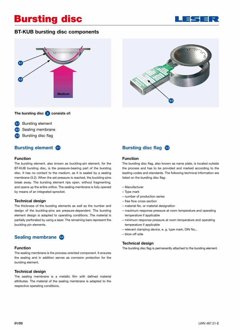
Bursting element 3.1
Function
The bursting element, also known as buckling-pin element, for the
BT-KUB bursting disc, is the pressure-bearing part of the bursting
disc. It has no contact to the medium, as it is sealed by a sealing
membrane (3.2). When the set pressure is reached, the buckling-pins
break away. The bursting element rips open, without fragmenting,
and opens up the entire orifice. The sealing membrane is fully opened
by means of an integrated sprocket.
Technical designThe thickness of the bursting elements as well as the number and
design of the buckling-pins are pressure-dependent. The bursting
element design is adapted to operating conditions. The material is
partially perforated by using a laser. The remaining bars represent the
buckling pin elements.
Sealing membrane 3.2
Function The sealing membrane is the process-oriented component. It ensures
the sealing and in addition serves as corrosion protection for the
bursting element.
Technical designThe sealing membrane is a metallic film with defined material
attributes. The material of the sealing membrane is adapted to the
respective operating conditions.
Bursting disc flag 3.3
Function
The bursting disc flag, also known as name plate, is located outside
the process and has to be provided and marked according to the
leading codes and standards. The following technical information are
listed on the bursting disc flag:
– Manufacturer
– Type mark
– number of production series
– free flow cross-section
– material No. or material designation
– maximum response pressure at room temperature and operating
temperature if applicable
– minimum response pressure at room temperature and operating
temperature if applicable
– relevant clamping device, e. g. type mark, DIN No.,
– blow-off side
Technical designThe bursting disc flag is permanently attached to the bursting element.
The bursting disc 3 consists of:
3.1 Bursting element3.2 Sealing membrane3.3 Bursting disc flag
BT-KUB bursting disc components
3.1
3.2
3.3
Medium
01/04LWN 487.21-E
Space monitoring deviceSpace monitoring device
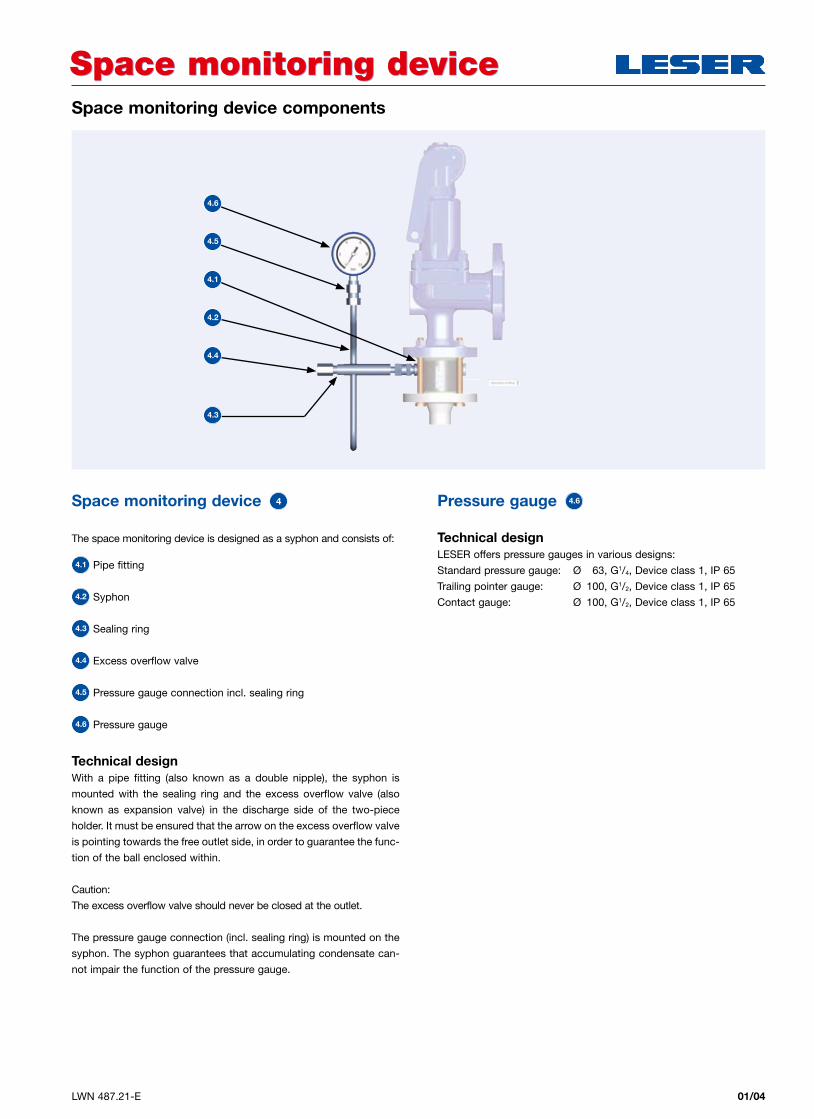
Space monitoring device 4
The space monitoring device is designed as a syphon and consists of:
4.1 Pipe fitting
4.2 Syphon
4.3 Sealing ring
4.4 Excess overflow valve
4.5 Pressure gauge connection incl. sealing ring
4.6 Pressure gauge
Technical designWith a pipe fitting (also known as a double nipple), the syphon is
mounted with the sealing ring and the excess overflow valve (also
known as expansion valve) in the discharge side of the two-piece
holder. It must be ensured that the arrow on the excess overflow valve
is pointing towards the free outlet side, in order to guarantee the func-
tion of the ball enclosed within.
Caution:
The excess overflow valve should never be closed at the outlet.
The pressure gauge connection (incl. sealing ring) is mounted on the
syphon. The syphon guarantees that accumulating condensate can-
not impair the function of the pressure gauge.
Pressure gauge 4.6
Technical designLESER offers pressure gauges in various designs:
Standard pressure gauge: Ø 63, G1/4, Device class 1, IP 65
Trailing pointer gauge: Ø 100, G1/2, Device class 1, IP 65
Contact gauge: Ø 100, G1/2, Device class 1, IP 65
Space monitoring device components
4.6
4.5
4.1
4.2
4.4
4.3
01/05 LWN 487.21-E
Codes and standards for safety valves and bursting discs in combination
Codes and standardsCodes and standards
AD 2000-Merkblatt A1, par.: 5.4.1.1Bursting safety devices can be arranged either before or after the safety
valve. A bursting device – safety valve – bursting device arrangement
is also possible.
EN ISO 4126-3, par.: 3.1A combination device comprises a bursting disc and separated from
the safety valve inlet by no more than a length equivalent to five times
the nominal size of the inlet piping.
ASME Section VIII Division 1 par.: UG-127 3bA rupture disc device may be installed between a pressure relief valve
and a vessel.
API 520 Part 2, par.: 4.6A rupture disc device may be installed between a pressure relief valve
and a vessel or on the downstream side of a pressure relief valve.
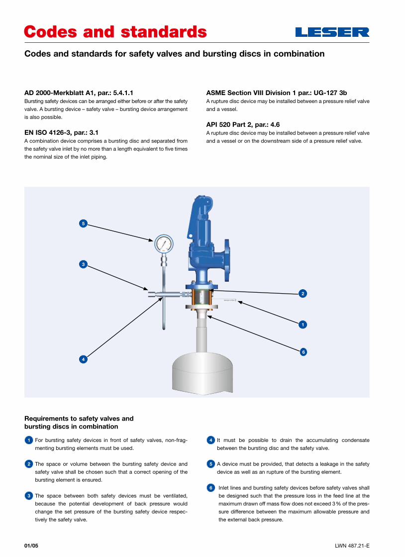
Requirements to safety valves and bursting discs in combination
1 For bursting safety devices in front of safety valves, non-frag-
menting bursting elements must be used.
2 The space or volume between the bursting safety device and
safety valve shall be chosen such that a correct opening of the
bursting element is ensured.
3 The space between both safety devices must be ventilated,
because the potential development of back pressure would
change the set pressure of the bursting safety device respec-
tively the safety valve.
4 It must be possible to drain the accumulating condensate
between the bursting disc and the safety valve.
5 A device must be provided, that detects a leakage in the safety
device as well as an rupture of the bursting element.
6 Inlet lines and bursting safety devices before safety valves shall
be designed such that the pressure loss in the feed line at the
maximum drawn off mass flow does not exceed 3% of the pres-
sure difference between the maximum allowable pressure and
the external back pressure.
5
3
4
2
1
6
01/06LWN 487.21-E
Installation and maintenanceInstallation and maintenance
Sizing of the combinationThrough testing, the BT-KUB bursting discs by REMBE® GmbH
SAFETY+CONTROL are optimally adapted to LESER safety valves.
No flow loss occurs due to a ruptured bursting disc in the inlet line to
the safety valve, which means that the combination can be designed
as an individual safety valve This has been tested and certified by
TÜV within the scope of safety valve approval.
However, at sizing of the combination according to ASME Sec. VIII
Div. 1, it must still be ensured that a correction factor of 0.9 in terms of
performance of the individual safety valve be included in the calcula-
tion. LESER recommends that the bursting pressure of the bursting
disc should be arranged to be equal to the set pressure of the safety
valve.
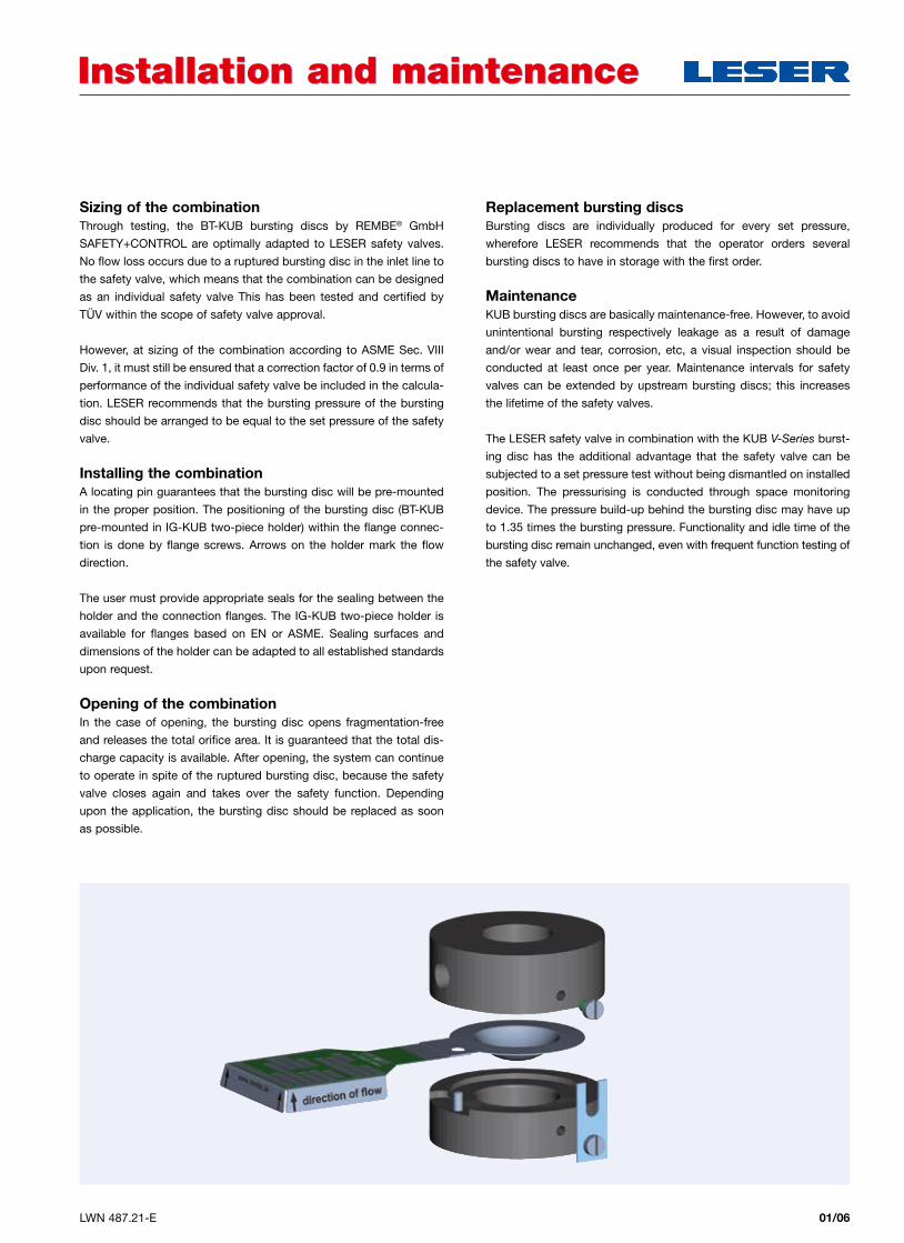
Installing the combinationA locating pin guarantees that the bursting disc will be pre-mounted
in the proper position. The positioning of the bursting disc (BT-KUB
pre-mounted in IG-KUB two-piece holder) within the flange connec-
tion is done by flange screws. Arrows on the holder mark the flow
direction.
The user must provide appropriate seals for the sealing between the
holder and the connection flanges. The IG-KUB two-piece holder is
available for flanges based on EN or ASME. Sealing surfaces and
dimensions of the holder can be adapted to all established standards
upon request.
Opening of the combinationIn the case of opening, the bursting disc opens fragmentation-free
and releases the total orifice area. It is guaranteed that the total dis-
charge capacity is available. After opening, the system can continue
to operate in spite of the ruptured bursting disc, because the safety
valve closes again and takes over the safety function. Depending
upon the application, the bursting disc should be replaced as soon
as possible.
Replacement bursting discsBursting discs are individually produced for every set pressure,
wherefore LESER recommends that the operator orders several
bursting discs to have in storage with the first order.
MaintenanceKUB bursting discs are basically maintenance-free. However, to avoid
unintentional bursting respectively leakage as a result of damage
and/or wear and tear, corrosion, etc, a visual inspection should be
conducted at least once per year. Maintenance intervals for safety
valves can be extended by upstream bursting discs; this increases
the lifetime of the safety valves.
The LESER safety valve in combination with the KUB V-Series burst-
ing disc has the additional advantage that the safety valve can be
subjected to a set pressure test without being dismantled on installed
position. The pressurising is conducted through space monitoring
device. The pressure build-up behind the bursting disc may have up
to 1.35 times the bursting pressure. Functionality and idle time of the
bursting disc remain unchanged, even with frequent function testing of
the safety valve.
01/07 LWN 487.21-E
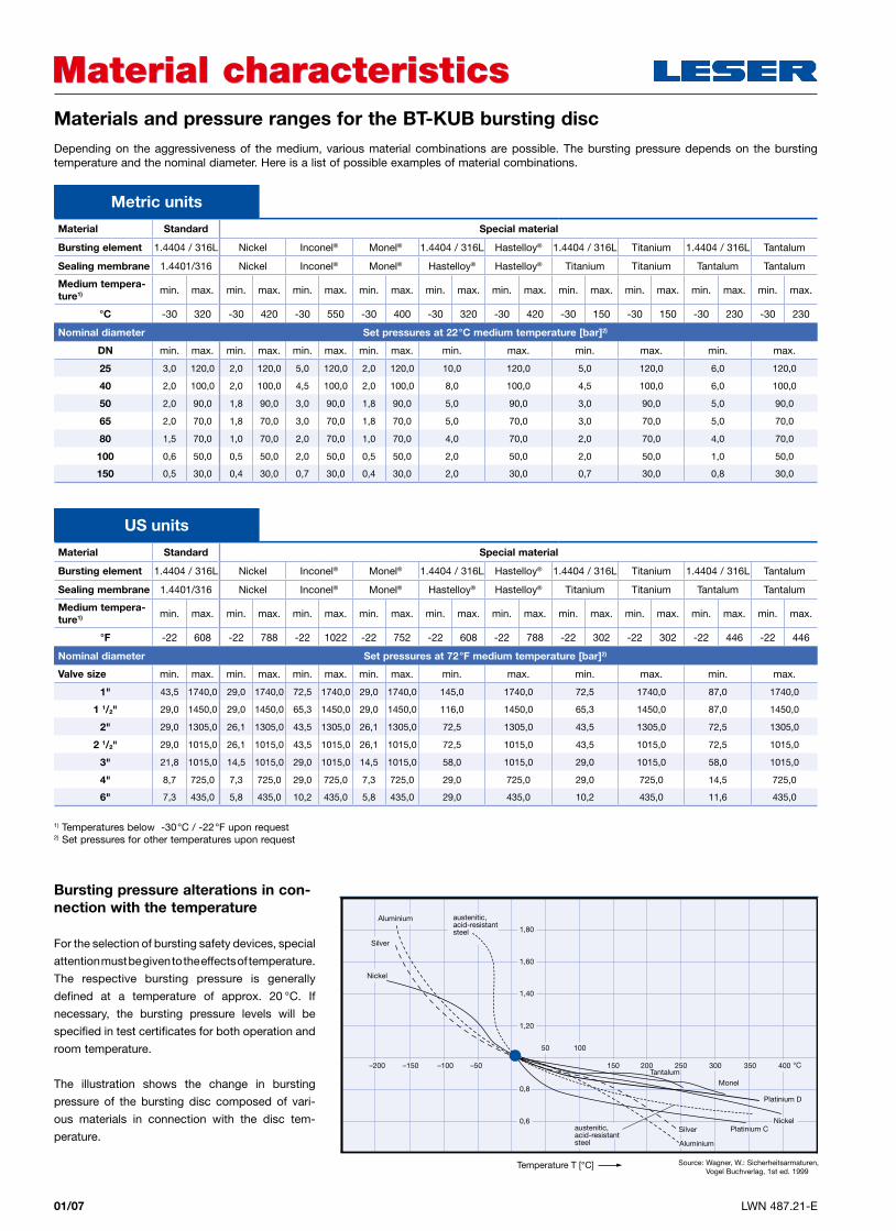
Material characteristicsMaterial characteristicsMaterials and pressure ranges for the BT-KUB bursting discDepending on the aggressiveness of the medium, various material combinations are possible. The bursting pressure depends on the bursting temperature and the nominal diameter. Here is a list of possible examples of material combinations.
Metric units
Material Standard Special material
Bursting element 1.4404 / 316L Nickel Inconel® Monel® 1.4404 / 316L Hastelloy® 1.4404 / 316L Titanium 1.4404 / 316L Tantalum
Sealing membrane 1.4401/316 Nickel Inconel® Monel® Hastelloy® Hastelloy® Titanium Titanium Tantalum Tantalum
Medium tempera-ture1) min. max. min. max. min. max. min. max. min. max. min. max. min. max. min. max. min. max. min. max.
°C -30 320 -30 420 -30 550 -30 400 -30 320 -30 420 -30 150 -30 150 -30 230 -30 230
Nominal diameter Set pressures at 22°C medium temperature [bar]2)
DN min. max. min. max. min. max. min. max. min. max. min. max. min. max.
25 3,0 120,0 2,0 120,0 5,0 120,0 2,0 120,0 10,0 120,0 5,0 120,0 6,0 120,0
40 2,0 100,0 2,0 100,0 4,5 100,0 2,0 100,0 8,0 100,0 4,5 100,0 6,0 100,0
50 2,0 90,0 1,8 90,0 3,0 90,0 1,8 90,0 5,0 90,0 3,0 90,0 5,0 90,0
65 2,0 70,0 1,8 70,0 3,0 70,0 1,8 70,0 5,0 70,0 3,0 70,0 5,0 70,0
80 1,5 70,0 1,0 70,0 2,0 70,0 1,0 70,0 4,0 70,0 2,0 70,0 4,0 70,0
100 0,6 50,0 0,5 50,0 2,0 50,0 0,5 50,0 2,0 50,0 2,0 50,0 1,0 50,0
150 0,5 30,0 0,4 30,0 0,7 30,0 0,4 30,0 2,0 30,0 0,7 30,0 0,8 30,0
US units
Material Standard Special material
Bursting element 1.4404 / 316L Nickel Inconel® Monel® 1.4404 / 316L Hastelloy® 1.4404 / 316L Titanium 1.4404 / 316L Tantalum
Sealing membrane 1.4401/316 Nickel Inconel® Monel® Hastelloy® Hastelloy® Titanium Titanium Tantalum Tantalum
Medium tempera-ture1) min. max. min. max. min. max. min. max. min. max. min. max. min. max. min. max. min. max. min. max.
°F -22 608 -22 788 -22 1022 -22 752 -22 608 -22 788 -22 302 -22 302 -22 446 -22 446
Nominal diameter Set pressures at 72°F medium temperature [bar]2)
Valve size min. max. min. max. min. max. min. max. min. max. min. max. min. max.
1" 43,5 1740,0 29,0 1740,0 72,5 1740,0 29,0 1740,0 145,0 1740,0 72,5 1740,0 87,0 1740,0
1 1/2" 29,0 1450,0 29,0 1450,0 65,3 1450,0 29,0 1450,0 116,0 1450,0 65,3 1450,0 87,0 1450,0
2" 29,0 1305,0 26,1 1305,0 43,5 1305,0 26,1 1305,0 72,5 1305,0 43,5 1305,0 72,5 1305,0
2 1/2" 29,0 1015,0 26,1 1015,0 43,5 1015,0 26,1 1015,0 72,5 1015,0 43,5 1015,0 72,5 1015,0
3" 21,8 1015,0 14,5 1015,0 29,0 1015,0 14,5 1015,0 58,0 1015,0 29,0 1015,0 58,0 1015,0
4" 8,7 725,0 7,3 725,0 29,0 725,0 7,3 725,0 29,0 725,0 29,0 725,0 14,5 725,0
6" 7,3 435,0 5,8 435,0 10,2 435,0 5,8 435,0 29,0 435,0 10,2 435,0 11,6 435,0
1) Temperatures below -30°C / -22°F upon request2) Set pressures for other temperatures upon request
Bursting pressure alterations in con-nection with the temperature
For the selection of bursting safety devices, special
attention must be given to the effects of temperature.
The respective bursting pressure is generally
defined at a temperature of approx. 20 °C. If
necessary, the bursting pressure levels will be
specified in test certificates for both operation and
room temperature.
The illustration shows the change in bursting
pressure of the bursting disc composed of vari-
ous materials in connection with the disc tem-
perature.
Temperature T [°C]
–200 –150 –100 –50
1,80
1,60
1,40
1,20
0,8
0,6
50 100
150 250200 350300 400
Aluminium
Silver Platinium C
°C
Platinium D
Nickel
Monel
Tantalum
Nickel
Silver
Aluminium austenitic, acid-resistant steel
austenitic, acid-resistant steel
Source: Wagner, W.: Sicherheitsarmaturen, Vogel Buchverlag, 1st ed. 1999
01/08LWN 487.21-E
Signal bursting discSignal bursting discThe bursting disc is downstream of the safety valve.
For applications in which the bursting disc is downstream of the
safety valve, signal bursting discs are used. A signal bursting disc
serves to display the system state locally, for example, in the control
room. The initialisation of the signal is caused by the rupture of the
bursting element (signalisation wire). The signalisation also continues
after normalisation of pressure in the system lines, as a continuous
display is activated for non-reversible bursting.
The safety valve-bursting disc combination at the outlet is offered by
LESER as a special solution.
InstallationThe signal bursting disc is mounted on the outlet side of the safety
valve directly between the flange and the outlet line of the safety valve
and designed for a low overpressure of max. 1 bar. In this regard, it
must be ensured that back pressure cannot result in the premature
rupture of the signal bursting disc, which would cause an incorrect
display.
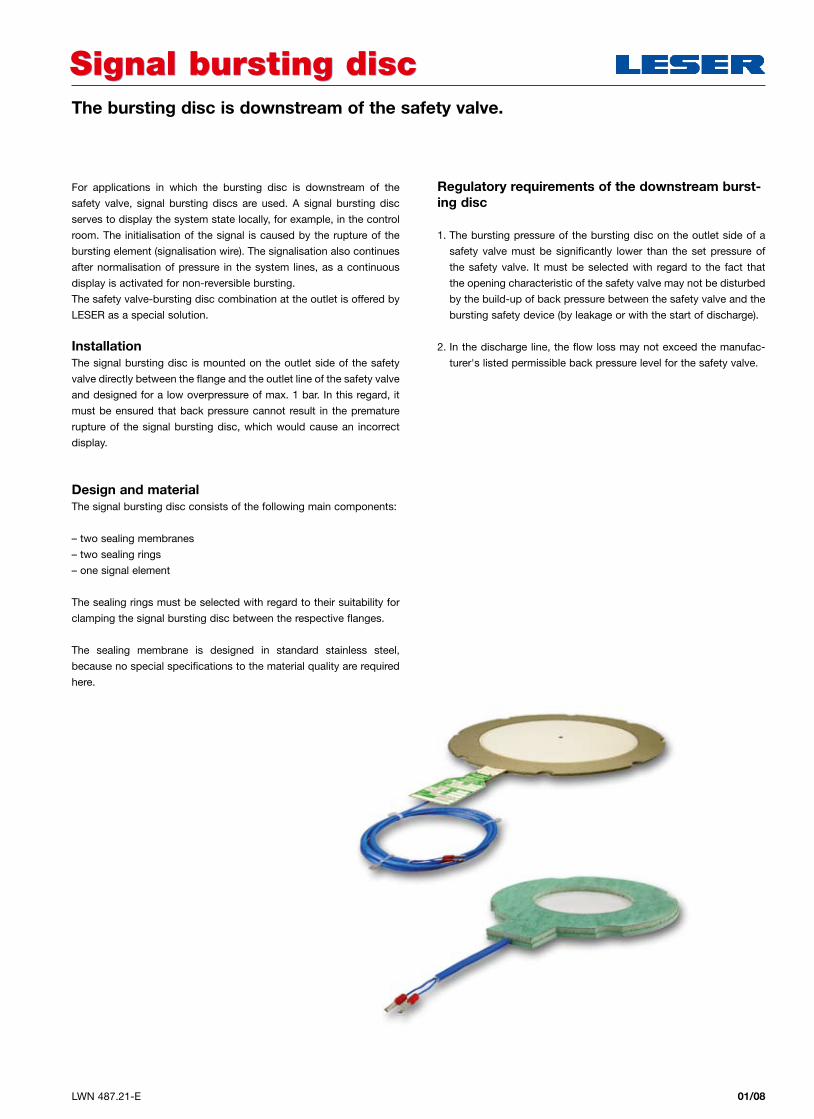
Design and materialThe signal bursting disc consists of the following main components:
– two sealing membranes
– two sealing rings
– one signal element
The sealing rings must be selected with regard to their suitability for
clamping the signal bursting disc between the respective flanges.
The sealing membrane is designed in standard stainless steel,
because no special specifications to the material quality are required
here.
Regulatory requirements of the downstream burst-ing disc
1. The bursting pressure of the bursting disc on the outlet side of a
safety valve must be significantly lower than the set pressure of
the safety valve. It must be selected with regard to the fact that
the opening characteristic of the safety valve may not be disturbed
by the build-up of back pressure between the safety valve and the
bursting safety device (by leakage or with the start of discharge).
2. In the discharge line, the flow loss may not exceed the manufac-
turer's listed permissible back pressure level for the safety valve.
02/01 LWN 487.21-E
Please select your LESER Safety Valve. Please use the "How to order" section of the corresponding product catalogue:
How to orderHow to order
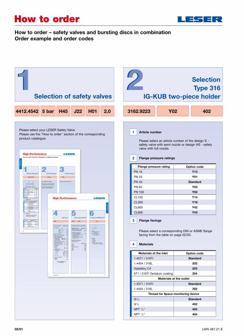
4412.4542 5 bar H45 J22 H01 2.0 3162.9223 402Y02
How to order – safety valves and bursting discs in combination Order example and order codes
22 SelectionType 316
IG-KUB two-piece holder11
Selection of safety valves
1 Article number
Please select an article number of the design S - safety valve with semi nozzle or design HS - safety valve with full nozzle.
3 Flange facings
Please select a corresponding DIN or ASME flange facing from the table on page 02/03.
2 Flange pressure ratings
4 Materials
Flange pressure rating Option code
PN 16 Y13
PN 25 Y01
PN 40 Standard
PN 63 Y03
PN 100 Y04
CL150 Y14
CL300 Y16
CL600 Y42
CL900 Y43
Materials at the inlet Option code
1.4571 / 316Ti Standard
1.4404 / 316L 202
Hastelloy C4 203
571 / 316Ti Tantalum coating 204
Materials at the outlet
1.4571 / 316Ti Standard
1.4404 / 316L 302
Thread for Space monitoring device
G1/4 Standard
G1/2 402
NPT 1/4" 403
NPT 1/2" 404
02/02LWN 487.21-E
How to orderHow to order
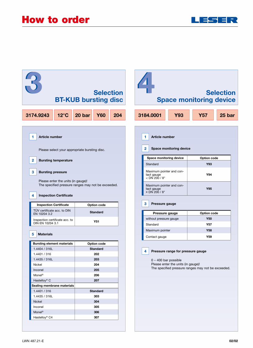
3174.9243 3184.000112°C Y9320 bar Y57Y60 25 bar204
Selection BT-KUB bursting disc
SelectionSpace monitoring device
33 44
1 Article number
Please select your appropriate bursting disc.
4 Pressure range for pressure gauge
0 – 400 bar possiblePlease enter the units (in gauge)!The specified pressure ranges may not be exceeded.
1 Article number
3 Pressure gauge
2 Space monitoring device
Pressure gauge Option code
without pressure gauge Y50
Standard Y57
Maximum pointer Y58
Contact gauge Y59
Space monitoring device Option code
Standard Y93
Maximum pointer and con-tact gauge < DN 200 / 8"
Y94
Maximum pointer and con-tact gauge ≥ DN 200 / 8"
Y95
3 Bursting pressure
Please enter the units (in gauge)!The specified pressure ranges may not be exceeded.
2 Bursting temperature
5 Materials
4 Inspection Certificate
Inspection Certificate Option code
TÜV certificate acc. to DIN EN 10204 3.2 Standard
Inspection certificate acc. to DIN EN 10204 3.1 Y51
Bursting element materials Option code
1.4404 / 316L Standard
1.4401 / 316 202
1.4435 / 316L 203
Nickel 204
Inconel 205
Monel® 206
Hastelloy® C 207
Sealing membrane materials
1.4401 / 316 Standard
1.4435 / 316L 303
Nickel 304
Inconel 305
Monel® 306
Hastelloy® C4 307
02/03 LWN 487.21-E
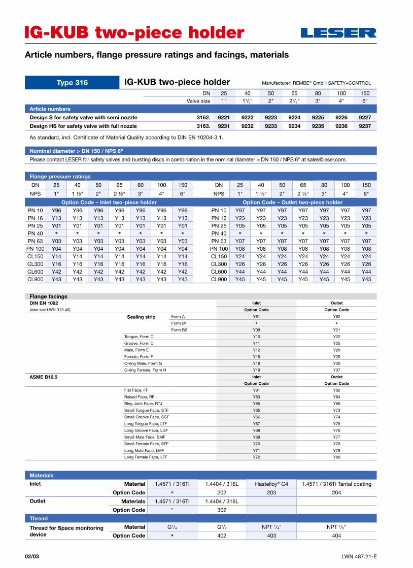
Article numbers, flange pressure ratings and facings, materials
IG-KUB two-piece holderIG-KUB two-piece holder
Nominal diameter > DN 150 / NPS 6"
Please contact LESER for safety valves and bursting discs in combination in the nominal diameter > DN 150 / NPS 6" at [email protected].
As standard, incl. Certificate of Material Quality according to DIN EN 10204-3.1.
Flange pressure ratings
DN 25 40 50 65 80 100 150 DN 25 40 50 65 80 100 150
NPS 1" 1 ½" 2" 2 ½" 3" 4" 6" NPS 1" 1 ½" 2" 2 ½" 3" 4" 6"
Option Code – Inlet two-piece holder Option Code – Outlet two-piece holder
PN 10 Y96 Y96 Y96 Y96 Y96 Y96 Y96 PN 10 Y97 Y97 Y97 Y97 Y97 Y97 Y97PN 16 Y13 Y13 Y13 Y13 Y13 Y13 Y13 PN 16 Y23 Y23 Y23 Y23 Y23 Y23 Y23PN 25 Y01 Y01 Y01 Y01 Y01 Y01 Y01 PN 25 Y05 Y05 Y05 Y05 Y05 Y05 Y05PN 40 * * * * * * * PN 40 * * * * * * *PN 63 Y03 Y03 Y03 Y03 Y03 Y03 Y03 PN 63 Y07 Y07 Y07 Y07 Y07 Y07 Y07PN 100 Y04 Y04 Y04 Y04 Y04 Y04 Y04 PN 100 Y08 Y08 Y08 Y08 Y08 Y08 Y08CL150 Y14 Y14 Y14 Y14 Y14 Y14 Y14 CL150 Y24 Y24 Y24 Y24 Y24 Y24 Y24CL300 Y16 Y16 Y16 Y16 Y16 Y16 Y16 CL300 Y26 Y26 Y26 Y26 Y26 Y26 Y26CL600 Y42 Y42 Y42 Y42 Y42 Y42 Y42 CL600 Y44 Y44 Y44 Y44 Y44 Y44 Y44CL900 Y43 Y43 Y43 Y43 Y43 Y43 Y43 CL900 Y45 Y45 Y45 Y45 Y45 Y45 Y45
Flange facings DIN EN 1092 Inlet Outlet
(also see LWN 313.40) Option Code Option Code
Sealing strip Form A Y61 Y62
Form B1 * *Form B2 Y09 Y21
Tongue, Form C Y10 Y22
Groove, Form D Y11 Y25
Male, Form E Y12 Y28
Female, Form F Y15 Y29
O-ring Male, Form G Y18 Y30
O-ring Female, Form H Y19 Y37
ASME B16.5 Inlet Outlet
Option Code Option Code
Flat Face, FF Y81 Y82
Raised Face, RF Y83 Y84
Ring Joint Face, RTJ Y85 Y86
Small Tongue Face, STF Y65 Y73
Small Groove Face, SGF Y66 Y74
Long Tongue Face, LTF Y67 Y75
Long Groove Face, LGF Y68 Y76
Small Male Face, SMF Y69 Y77
Small Female Face, SFF Y70 Y78
Long Male Face, LMF Y71 Y79
Long Female Face, LFF Y72 Y80
Materials
Inlet Material 1.4571 / 316Ti 1.4404 / 316L Hastelloy® C4 1.4571 / 316Ti Tantal coating
Option Code * 202 203 204
Outlet Materials 1.4571 / 316Ti 1.4404 / 316L
Option Code * 302
Thread
Thread for Space monitoring device
Material G1/4 G1/2 NPT 1/4" NPT 1/2"
Option Code * 402 403 404
Type 316 IG-KUB two-piece holder DN 25 40 50 65 80 100 150
Valve size 1" 11/2" 2" 21/2" 3" 4" 6"
Article numbers
Design S for safety valve with semi nozzle 3162. 9221 9222 9223 9224 9225 9226 9227
Design HS for safety valve with full nozzle 3163. 9231 9232 9233 9234 9235 9236 9237
Manufacturer: REMBE® GmbH SAFETY+CONTROL
02/04LWN 487.21-E
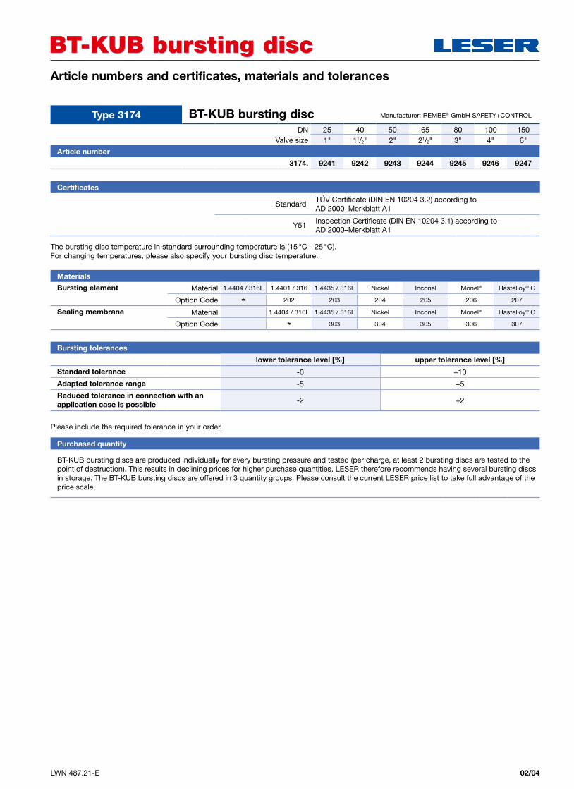
Article numbers and certificates, materials and tolerances
BT-KUB bursting discBT-KUB bursting disc
Purchased quantity
BT-KUB bursting discs are produced individually for every bursting pressure and tested (per charge, at least 2 bursting discs are tested to the point of destruction). This results in declining prices for higher purchase quantities. LESER therefore recommends having several bursting discsin storage. The BT-KUB bursting discs are offered in 3 quantity groups. Please consult the current LESER price list to take full advantage of the price scale.
Certificates
StandardTÜV Certificate (DIN EN 10204 3.2) according to AD 2000–Merkblatt A1
Y51Inspection Certificate (DIN EN 10204 3.1) according to AD 2000–Merkblatt A1
Materials
Bursting element Material 1.4404 / 316L 1.4401 / 316 1.4435 / 316L Nickel Inconel Monel® Hastelloy® C
Option Code * 202 203 204 205 206 207
Sealing membrane Material 1.4404 / 316L 1.4435 / 316L Nickel Inconel Monel® Hastelloy® C
Option Code * 303 304 305 306 307
Bursting tolerances
lower tolerance level [%] upper tolerance level [%]
Standard tolerance -0 +10
Adapted tolerance range -5 +5
Reduced tolerance in connection with an application case is possible -2 +2
Type 3174 BT-KUB bursting discDN 25 40 50 65 80 100 150
Valve size 1" 11/2" 2" 21/2" 3" 4" 6"
Article number
3174. 9241 9242 9243 9244 9245 9246 9247
Manufacturer: REMBE® GmbH SAFETY+CONTROL
The bursting disc temperature in standard surrounding temperature is (15 °C - 25 °C). For changing temperatures, please also specify your bursting disc temperature.
Please include the required tolerance in your order.
02/05 LWN 487.21-E
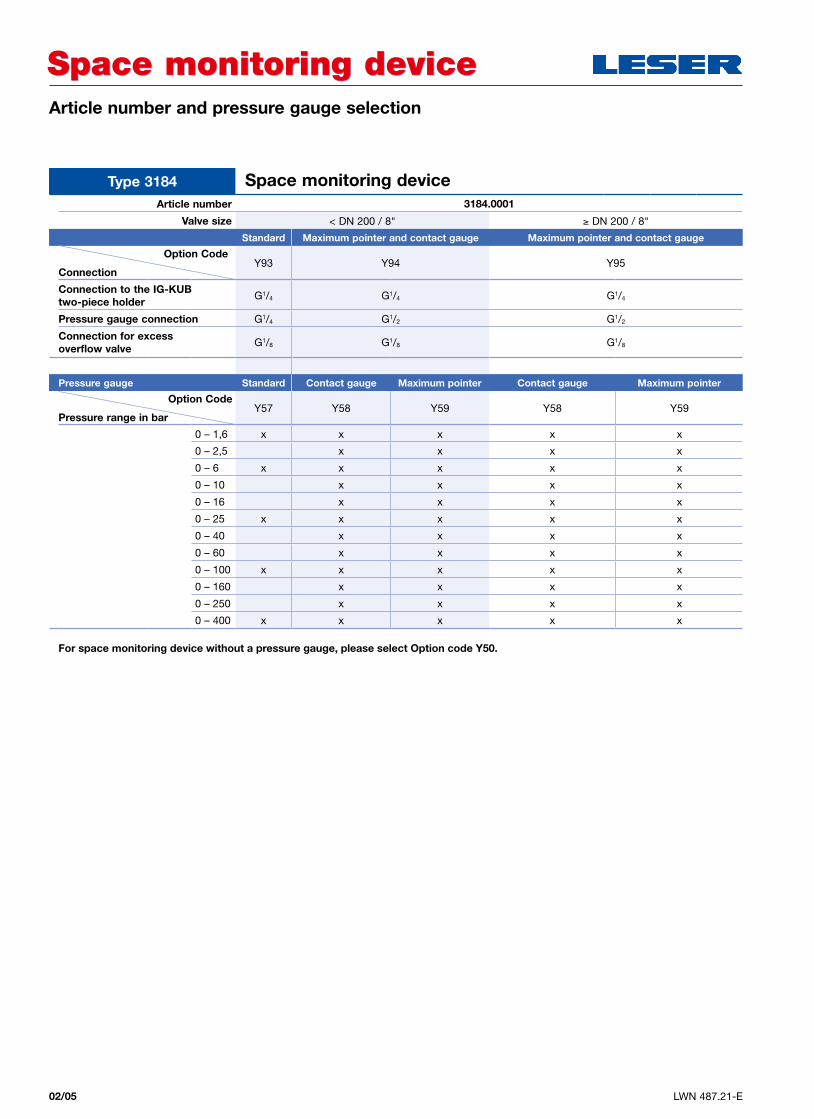
Article number and pressure gauge selection
Space monitoring deviceSpace monitoring device
Article number 3184.0001
Valve size < DN 200 / 8" ≥ DN 200 / 8"
Standard Maximum pointer and contact gauge Maximum pointer and contact gauge
Connection
Option CodeY93 Y94 Y95
Connection to the IG-KUB two-piece holder G1/4 G1/4 G1/4
Pressure gauge connection G1/4 G1/2 G1/2
Connection for excess overflow valve G1/8 G1/8 G1/8
Pressure gauge Standard Contact gauge Maximum pointer Contact gauge Maximum pointer
Pressure range in bar Option Code
Y57 Y58 Y59 Y58 Y59
0 – 1,6 x x x x x
0 – 2,5 x x x x
0 – 6 x x x x x
0 – 10 x x x x
0 – 16 x x x x
0 – 25 x x x x x
0 – 40 x x x x
0 – 60 x x x x
0 – 100 x x x x x
0 – 160 x x x x
0 – 250 x x x x
0 – 400 x x x x x
Type 3184 Space monitoring device
For space monitoring device without a pressure gauge, please select Option code Y50.
02/06LWN 487.21-E
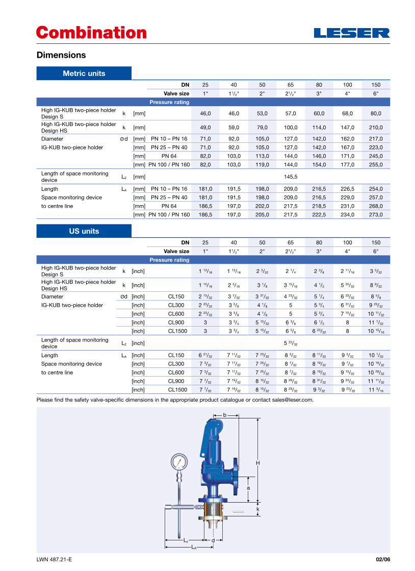
Dimensions
CombinationCombination
Metric unitsDN 25 40 50 65 80 100 150
Valve size 1" 11/2" 2" 21/2" 3" 4" 6"
Pressure ratingHigh IG-KUB two-piece holder Design S
k [mm] 46,0 46,0 53,0 57,0 60,0 68,0 80,0
High IG-KUB two-piece holder Design HS
k [mm] 49,0 59,0 79,0 100,0 114,0 147,0 210,0
Diameter Ø d [mm] PN 10 – PN 16 71,0 92,0 105,0 127,0 142,0 162,0 217,0
IG-KUB two-piece holder [mm] PN 25 – PN 40 71,0 92,0 105,0 127,0 142,0 167,0 223,0
[mm] PN 64 82,0 103,0 113,0 144,0 146,0 171,0 245,0
[mm] PN 100 / PN 160 82,0 103,0 119,0 144,0 154,0 177,0 255,0
Length of space monitoring device
LZ [mm] 145,5
Length LA [mm] PN 10 – PN 16 181,0 191,5 198,0 209,0 216,5 226,5 254,0
Space monitoring device [mm] PN 25 – PN 40 181,0 191,5 198,0 209,0 216,5 229,0 257,0
to centre line [mm] PN 64 186,5 197,0 202,0 217,5 218,5 231,0 268,0
[mm] PN 100 / PN 160 186,5 197,0 205,0 217,5 222,5 234,0 273,0
DN 25 40 50 65 80 100 150
Valve size 1" 11/2" 2" 21/2" 3" 4" 6"
Pressure ratingHigh IG-KUB two-piece holder Design S
k [inch] 1 13/16 1 13/16 2 3/32 2 1/4 2 3/8 2 11/16 3 5/32
High IG-KUB two-piece holder Design HS
k [inch] 1 15/16 2 5/16 3 1/8 3 15/16 4 1/2 5 25/32 8 9/32
Diameter Ød [inch] CL150 2 15/32 3 7/32 3 31/32 4 23/32 5 1/4 6 23/32 8 5/8
IG-KUB two-piece holder [inch] CL300 2 23/32 3 5/8 4 1/8 5 5 3/4 6 31/32 9 23/32
[inch] CL600 2 23/32 3 5/8 4 1/8 5 5 3/4 7 15/32 10 11/32
[inch] CL900 3 3 3/4 5 15/32 6 3/8 6 1/2 8 11 7/32
[inch] CL1500 3 3 3/4 5 15/32 6 3/8 6 23/32 8 10 15/16
Length of space monitoring device
LZ [inch] 5 23/32
Length LA [inch] CL150 6 31/32 7 11/32 7 23/32 8 3/32 8 11/32 9 3/32 10 1/32
Space monitoring device [inch] CL300 7 3/32 7 17/32 7 25/32 8 7/32 8 19/32 9 7/32 10 19/32
to centre line [inch] CL600 7 3/32 7 17/32 7 25/32 8 7/32 8 19/32 9 15/32 10 29/32
[inch] CL900 7 7/32 7 19/32 8 15/32 8 29/32 8 31/32 9 23/32 11 11/32
[inch] CL1500 7 7/32 7 19/32 8 15/32 8 29/32 9 3/32 9 23/32 11 3/16
US units
Please find the safety valve-specific dimensions in the appropriate product catalogue or contact [email protected].
H
k
a
LA
Lz d
b

Bursting disc catalogEdition July 2009
LWN 487.21-E / 0777.5657 / 3000
20537 Hamburg, Wendenstr. 133-13520506 Hamburg, P.O. Box 26 16 51
Fon +49 (40) 251 65-100Fax +49 (40) 251 65-500
LESER GmbH & Co. KG E-Mail: [email protected]
The-Safety-Valve.com