Embed Size (px)
Citation preview
VAREC BIOGAS 244W SeriesWASTE GAS BURNER IGNITION SYSTEM
The Varec Biogas 244W Series Waste Gas Burner is a highlyreliable flare and ignition system ideal for use in burning excess biogas.
Varec Biogas reserves the right to change product design and specifications without notice.Copyright © 2015 by Varec Biogas a Division of Westech Industrial Inc.
Operation
The Varec Biogas 244WS Series Burner is a state-of-the-art, candle-stick flare. The burner utilizes a patented pilot ignition system. Pilot gas and air are mixed and ignited at ground level, remote from the burner stack. This controlled method results in a stable pilot flame with an ideal gas-to-air ratio. The pilot burns a true stoichiometric, non-smoking flame. It is not affected by changes in the biogas flow rate or BTU content.
BURNERS/ FLARES
Introduction
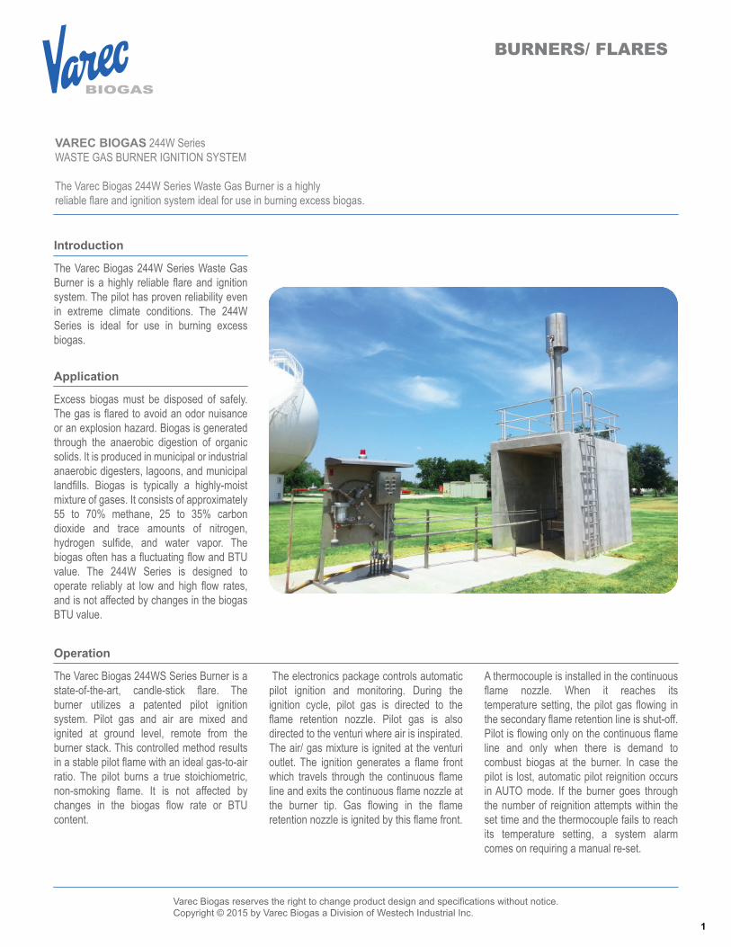
The Varec Biogas 244W Series Waste Gas Burner is a highly reliable flare and ignition system. The pilot has proven reliability even in extreme climate conditions. The 244W Series is ideal for use in burning excess biogas.
Application
Excess biogas must be disposed of safely. The gas is flared to avoid an odor nuisance or an explosion hazard. Biogas is generated through the anaerobic digestion of organic solids. It is produced in municipal or industrial anaerobic digesters, lagoons, and municipal landfills. Biogas is typically a highly-moist mixture of gases. It consists of approximately 55 to 70% methane, 25 to 35% carbon dioxide and trace amounts of nitrogen, hydrogen sulfide, and water vapor. The biogas often has a fluctuating flow and BTU value. The 244W Series is designed to operate reliably at low and high flow rates, and is not affected by changes in the biogas BTU value.
The electronics package controls automatic pilot ignition and monitoring. During the ignition cycle, pilot gas is directed to the flame retention nozzle. Pilot gas is also directed to the venturi where air is inspirated. The air/ gas mixture is ignited at the venturi outlet. The ignition generates a flame front which travels through the continuous flame line and exits the continuous flame nozzle at the burner tip. Gas flowing in the flame retention nozzle is ignited by this flame front.
A thermocouple is installed in the continuous flame nozzle. When it reaches its temperature setting, the pilot gas flowing in the secondary flame retention line is shut-off. Pilot is flowing only on the continuous flame line and only when there is demand to combust biogas at the burner. In case the pilot is lost, automatic pilot reignition occurs in AUTO mode. If the burner goes through the number of reignition attempts within the set time and the thermocouple fails to reach its temperature setting, a system alarm comes on requiring a manual re-set.
1
Varec Biogas reserves the right to change product design and specifications without notice.Copyright © 2015 by Varec Biogas a Division of Westech Industrial Inc.
VAREC BIOGAS 244W Series WASTE GAS BURNER AND IGNITION SYSTEM
Design Features
The 244W Series design includes features that provide reliable and efficient operation. The flare can withstand wind loading of 150 mph (242 km/h) and wind speeds of 110 mph (180 km/h). Baffles, downdraft preventers, vortex vanes, and secondary stacks are not required. The inclined continuous pilot nozzle provides a long-profile flame which penetrates the waste gas as it passes through. This feature ensures the biogas is ignited at near zero flows.
Installation is simplified. The burner allows high turndown ratios; therefore there is no need to manifold several burners together. Pre-cast concrete supports are not necessary. The burner includes an integral ANSI 150 RF flange. The contractor just has to provide a matching flange and pipe supports. These features keep installation costs to a minimum.
The venturi-driven pilot burns at higher temperature when fueled by propane, natural gas or biogas (see 244WG or 244WL systems). This improves H2S conversion, which reduces odor to a minimum. The heavy-wall continuous pilot nozzle and flame retention nozzle are both mounted at the burner tip. The nozzles are designed to withstand the elevated pilot temperature and H2S environment. A heavily protected thermocouple permits pilot flame monitoring. The thermocouple provides an extremely reliable pilot signal.
Contacts are provided as standard for remote pilot indication and system alarm. HAND and AUTO ignition mode is selectable.
The Varec Biogas 244WS is designed to operate satisfactorily in very cold climates.
BLOWER PACKAGEA blower package is available when the pilot gas supply is less than 10 psig (70 kPa) and as low as 8” W.C. (2 kPa) pressure.
The burner stack and control panel design is the same as the standard 244WS with a venturi.
This option can also handle the same burner flow capacities. Local or “Remote-Start” features are still available. You retain the advantage of having the theory of operation using flamefront technology.
A blower panel replaces the venturi and valve + regulator panel and utilizes a blower to pre-mix air and pilot gas. The blower comes with an air/gas mixing chamber to achieve proper airgas mixture and is ignited at the chamber exit. It also includes the pilot gas solenoid valves, regulators and gauges required to control pilot gas.
See the Sample Specification Product Data Sheet for more information.
244WG Series Low Pressure Pilot Ignition SystemThe Varec Biogas 244WG option is specifically designed to burn biogas efficiently with the use of low pressure biogas for pilot fuel (4” < pilot gas pressure < 14” WC) without the requirement of blower-assisted fuel or air.
45 degrees elbows are allowed providing for greater flexibility during design and installation.
The "L" ignition system comes equipped with a blower to pre-mix air with the pilot gas to achieve the proper air-gas mixture required for combustion. This pre-mixing of the pilot gas and air insures that the pilot stays lit under virtually all flow and weather conditions.
The sparkplug is located at the exit of the 2" mixing chamber. A flame front travels on the 2" pilot gas line and as it exits the burner stack, the 1/2" retention line is there to capture the flame front. The angled design of the pilot gas piping has been field tested to achieve the proper air-gas mixture needed for optimum combustion of the waste gas. All serviceable items are located remotely from the burner stack which protects all electrical components from the heat of combustion. More importantly, Operators are protected from radiant heat effects from the waste gas burner when it is in operation.
The large venturi design allows the ignition components to be mounted up to 100 feet (30 m) away from the burner. The control package may also be mounted at this distance without suffering any performance loss.
The venturi includes a backflash preventer for safety. An anti-clog orifice is supplied which eliminates the need for pilot filters. The Varec Biogas Model 244WS is designed with operator safety in mind. All hi-tension leads and sparking devices are located a safe distance from the flame. Typical adjustments and maintenance are performed at ground level, away from the heat of combustion. Ignition components are also located remote from the burner, which provides optimum serviceability.
The burner comes with two inspirating venturis to help pre-mix air and pilot gas and ensure pilot reliability and efficient combustion of biogas even with the low volume biogas pilot fuel. The control panel and pilot gas control components are mounted on stainless steel plate. It is installed a maximum of 10 feet horizontal distance from the waste gas burner. The pilot gas piping from the venturis to the waste gas burner connection must be a straight pipe – no pipe bends allowed. This will ensure that the stoichiometric gas can travel to the burner tip.
The 244WG also utilizes flamefront technology like the 244WS option and follows the same operation scheme.
244WL Series Low Pressure Pilot Ignition SystemThe 244WL ignition system utilizes the same flame from technology as the industry standard for our Model 244W Waste Gas Burners. The pilot gas control components panel can be mounted up to 70 ft. (seventy feet) from the burner stack. It can utilize biogas, natural gas or propane at pressures as low as 4" WC.
The 244WL ignition system no longer requires a straight pilot gas piping run from the pilot gas control components panel to the burner stack.
2
Varec Biogas reserves the right to change product design and specifications without notice.Copyright © 2015 by Varec Biogas a Division of Westech Industrial Inc.
VAREC BIOGAS 244W Series WASTE GAS BURNER AND IGNITION SYSTEM
Optional Features
“REMOTE-START”If biogas will be flared intermittently, an option to conserve pilot fuel is available through our “Remote-Start” pilot ignition option. It includes a pilot-gas supply solenoid valve, which opens when pilot ignition is required and remains open while the gas is flaring. The solenoid may be specified to: (a) fail open which will continue to deliver pilot fuel during a power failure and keep the burner operational in an emergency condition, or (b) fail close, which is used when a blower is available to deliver the biogas to the burner (“L” ignition system).
The “call for ignition” signal may be provided by a pressure switch, flow-switch, or through a contact change-over.
FLASHBACK PROTECTIONIt is recommended that suitable flame flashback protection be installed in fuel gas lines supplying any of the 244W burner systems. Please refer to 5200 Series Product Data Sheet for information.
CONTROLThe standard control panel is provided with a programmable logic controller (PLC). The PLC can be provided with HMI touch screen controls. Relay logic panels available upon request.
HIGH PRESSURE PILOT GAS SUPPLYNatural Gas or PropaneMin. Supply Pressure: 10 PSIG (70 kPa)Max. Supply Pressure: 100 PSIG (700 kPa)Recommended Pipe Length from Venturi to Continuous Flame Nozzle:Minimum Distance: 15 feet (5m)Maximum Distance: 100 feet (30m)
LOW PRESSURE PILOT GAS SUPPLYWhen available pilot gas pressure is less than 10PSIG (70 kPa) and greater than 4” WC.
BLOWER PACKAGENatural Gas or PropaneMinimum Supply Pressure: 6” - 8” WC Explosion Proof Motor and Switch, Standard
Recommended Pipe Length from blower package to continuous flame nozzle:Maximum distance: 33 feet (10m)
HEATER & THERMOSTATFor ambient temperatures below -200F (-290C), a heater and thermostat is recommended.
REMOTE SPARK GENERATORThe hi-tension lead wire supplied with the unit is a maximum 10 feet (3 m) in length. In cases where the control panel that houses the transformer cannot be located within 10 feet of the spark plug location, a remote generator can be specified.
The transformer is supplied in either a NEMA 4, 4X or 4 & 7 enclosure and located within 10 feet of the spark plug. This allows an operator to have the control panel installed further away from the burner for improved burner monitoring.
MaterialsBURNERStainless Steel Shroud and Upper 24” of Stack; Remainder Mild Steel, Standard.All 304SS or 316SS (Optional)
PILOT NOZZLES316 SS
THERMOCOUPLE316 SS
CONTROL ENCLOSURE1
NEMA 4, Steel Construction, StandardNEMA 4X, 316 SS Construction, OptionalNEMA 7, Aluminum Construction with O’ring or Steel, Optional
NOTES:1. UL Certified
Specifications
SIZES2”, 3”, 4”, 6”, 8”, 10” and 12”
CONNECTIONSBurner StackANSI 150 RF Flange
CONTROL PANELPower Supply Input:115/ 120 VAC, 60 Hz, Standard220/ 240 VAC, 50 Hz, Option220/ 240 VAC, 60 Hz, Option
Load:Maximum 10 AMPS at 120 VAC or5 AMPS at 220 VAC (50-/ 60 Hz)
Ambient Temperature Rating:-20°F to +131°F (-29°C to +55°C), Standard
REMOTE ALARM CONTACTSSPDT (NC, NO and Common) ContactsContact Rating:2 AMPS at 115 or 240 VAC (50/ 60 Hz)Funtion:Pilot Out and System Alarm
3
Varec Biogas reserves the right to change product design and specifications without notice.Copyright © 2015 by Varec Biogas a Division of Westech Industrial Inc.
VAREC BIOGAS 244W Series WASTE GAS BURNER AND IGNITION SYSTEM
Specifications
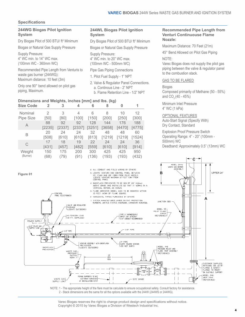
244WG Biogas Pilot Ignition SystemDry Biogas Pilot of 500 BTU/ ft3 MinimumBiogas or Natural Gas Supply PressureSupply Pressure:4” WC min. to 14” WC max.(100mm WC - 360mm WC)Recommended Pipe Length from Venturis to waste gas burner (244WG):Maximum distance: 10 feet (3m)Only one 90° bend allowed on pilot gas piping, Maximum.
244WL Biogas Pilot Ignition SystemDry Biogas Pilot of 500 BTU/ ft3 MinimumBiogas or Natural Gas Supply PressureSupply Pressure:4” WC min. to 20” WC max.(100mm WC - 500mm WC)Pipe Gas Piping Connections1. Pilot Fuel Supply - 1” NPT2. Valve & Regulator Panel Connections. a. Continous Line - 2” NPT b. Flame Retention Line - 1/2” NPT
Recommended Pipe Length from Venturi Continuouse Flame Nozzle:Maximum Distance: 70 Feet (21m)45° Bend Allowed on Pilot Gas PipingNOTE:Varec Biogas does not supply the pilot gas piping between the valve & regulator panel to the combustion stack.
GAS TO BE FLAREDBiogasComposed primarily of Methane (50 - 55%) and CO2 (40 - 45%)
Minimum Inlet Pressure4” WC (1 kPa)
OPTIONAL FEATURESAuto-Start Signal (Specify With)Dry Contact, StandardExplosion Proof Pressure SwitchOperating Range: 4” - 20” (100mm - 500mm) WCDeadband: Approximately 0.5” (13mm) WC
NOTE: 1 - The appropriate height of the flare must be calculate to ensure occupational safety. Consult factory for assistance. 2 - Stack dimensions are the same for all the options available with the 244W (244WS or 244WG).
6[150]128
[3251]32
[813]22
[559]300
(136)
NominalPipe Size
A
B
C
Weight(Burner)
2[50]88
[2235]20
[508]17
[431]150(68)
3[80]92
[2337]24
[610]18
[457]175(79)
4[100]92
[2337]24
[610]19
[482]200(91)
Dimensions and Weights, inches [mm] and lbs. (kg)Size Code 2 3 4 6 8 0 1
8[200]144
[3658]48
[1219]24
[610]425
(193)
12[300]188
[4775]60
[1524]36
[914]950
(432)
10[250]176
[4470]48
[1219]24
[610]425
(193)
Figure 01
4
Varec Biogas reserves the right to change product design and specifications without notice.Copyright © 2015 by Varec Biogas a Division of Westech Industrial Inc.
VAREC BIOGAS 244W Series WASTE GAS BURNER AND IGNITION SYSTEM
Specifications
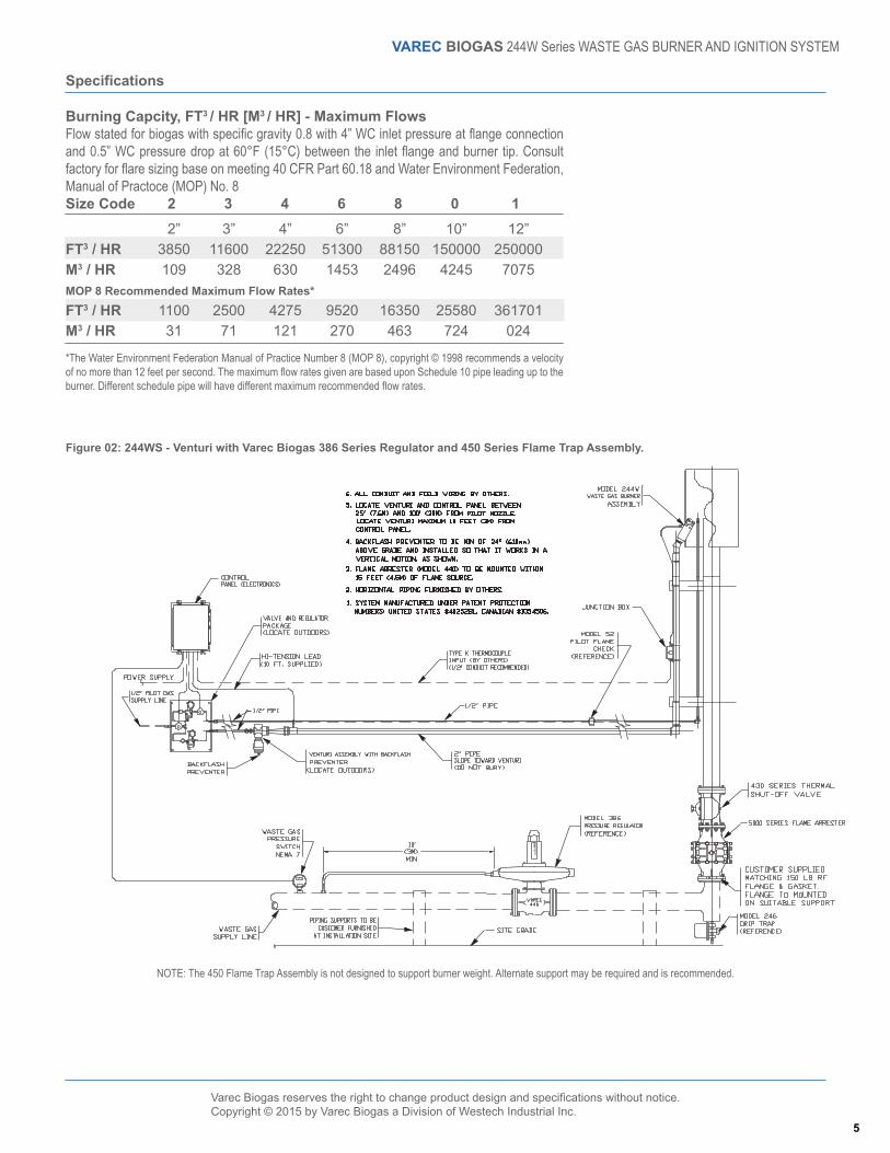
6”513001453
9520270
FT3 / HRM3 / HRMOP 8 Recommended Maximum Flow Rates*
FT3 / HRM3 / HR
2”3850109
110031
3”11600328
250071
4”22250630
4275121
Burning Capcity, FT3 / HR [M3 / HR] - Maximum FlowsFlow stated for biogas with specific gravity 0.8 with 4” WC inlet pressure at flange connection and 0.5” WC pressure drop at 60°F (15°C) between the inlet flange and burner tip. Consult factory for flare sizing base on meeting 40 CFR Part 60.18 and Water Environment Federation, Manual of Practoce (MOP) No. 8Size Code 2 3 4 6 8 0 1
8”881502496
16350463
12”2500007075
361701024
10”1500004245
25580724
NOTE: The 450 Flame Trap Assembly is not designed to support burner weight. Alternate support may be required and is recommended.
Figure 02: 244WS - Venturi with Varec Biogas 386 Series Regulator and 450 Series Flame Trap Assembly.
*The Water Environment Federation Manual of Practice Number 8 (MOP 8), copyright © 1998 recommends a velocity of no more than 12 feet per second. The maximum flow rates given are based upon Schedule 10 pipe leading up to the burner. Different schedule pipe will have different maximum recommended flow rates.
5
Varec Biogas reserves the right to change product design and specifications without notice.Copyright © 2015 by Varec Biogas a Division of Westech Industrial Inc.
VAREC BIOGAS 244W Series WASTE GAS BURNER AND IGNITION SYSTEM
Specifications
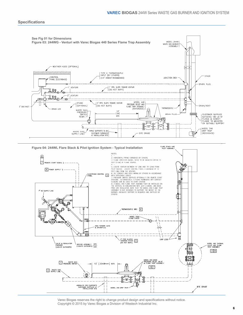
See Fig 01 for DimensionsFigure 03: 244WG - Venturi with Varec Biogas 440 Series Flame Trap Assembly
Figure 04: 244WL Flare Stack & Pilot Ignition System - Typical Installation
6
Varec Biogas reserves the right to change product design and specifications without notice.Copyright © 2015 by Varec Biogas a Division of Westech Industrial Inc.
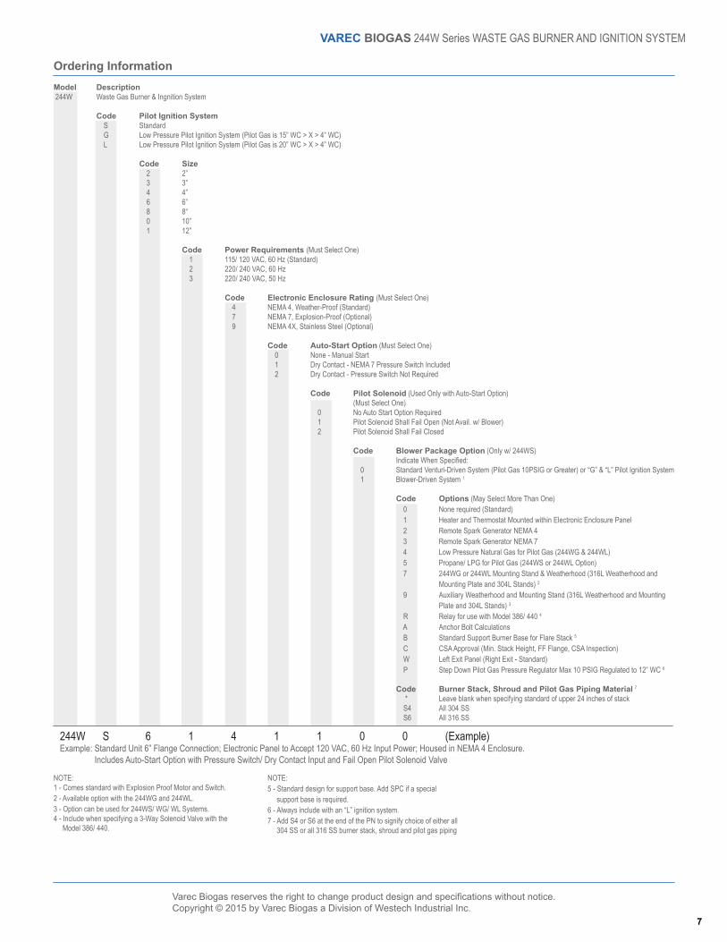
Ordering InformationModel Description 244W Waste Gas Burner & Ingnition System
Code Pilot Ignition System S Standard G Low Pressure Pilot Ignition System (Pilot Gas is 15” WC > X > 4” WC) L Low Pressure Pilot Ignition System (Pilot Gas is 20” WC > X > 4” WC)
Code Size 2 2” 3 3” 4 4” 6 6” 8 8“ 0 10” 1 12”
Code Power Requirements (Must Select One) 1 115/ 120 VAC, 60 Hz (Standard) 2 220/ 240 VAC, 60 Hz 3 220/ 240 VAC, 50 Hz
Code Electronic Enclosure Rating (Must Select One) 4 NEMA 4, Weather-Proof (Standard) 7 NEMA 7, Explosion-Proof (Optional) 9 NEMA 4X, Stainless Steel (Optional)
Code Auto-Start Option (Must Select One) 0 None - Manual Start 1 Dry Contact - NEMA 7 Pressure Switch Included 2 Dry Contact - Pressure Switch Not Required
Code Pilot Solenoid (Used Only with Auto-Start Option) (Must Select One) 0 No Auto Start Option Required 1 Pilot Solenoid Shall Fail Open (Not Avail. w/ Blower) 2 Pilot Solenoid Shall Fail Closed
Code Blower Package Option (Only w/ 244WS) Indicate When Specified: 0 Standard Venturi-Driven System (Pilot Gas 10PSIG or Greater) or “G” & “L” Pilot Ignition System 1 Blower-Driven System 1
Code Options (May Select More Than One) 0 None required (Standard) 1 Heater and Thermostat Mounted within Electronic Enclosure Panel 2 Remote Spark Generator NEMA 4 3 Remote Spark Generator NEMA 7 4 Low Pressure Natural Gas for Pilot Gas (244WG & 244WL) 5 Propane/ LPG for Pilot Gas (244WS or 244WL Option) 7 244WG or 244WL Mounting Stand & Weatherhood (316L Weatherhood and Mounting Plate and 304L Stands) 2
9 Auxiliary Weatherhood and Mounting Stand (316L Weatherhood and Mounting Plate and 304L Stands) 3
R Relay for use with Model 386/ 440 4
A Anchor Bolt Calculations B Standard Support Burner Base for Flare Stack 5
C CSA Approval (Min. Stack Height, FF Flange, CSA Inspection) W Left Exit Panel (Right Exit - Standard) P Step Down Pilot Gas Pressure Regulator Max 10 PSIG Regulated to 12” WC 6
Code Burner Stack, Shroud and Pilot Gas Piping Material 7
* Leave blank when specifying standard of upper 24 inches of stack S4 All 304 SS S6 All 316 SS
VAREC BIOGAS 244W Series WASTE GAS BURNER AND IGNITION SYSTEM
NOTE:1 - Comes standard with Explosion Proof Motor and Switch.2 - Available option with the 244WG and 244WL.3 - Option can be used for 244WS/ WG/ WL Systems.4 - Include when specifying a 3-Way Solenoid Valve with the Model 386/ 440.
244W S 6 1 4 1 1 0 0 (Example)Example: Standard Unit 6” Flange Connection; Electronic Panel to Accept 120 VAC, 60 Hz Input Power; Housed in NEMA 4 Enclosure. Includes Auto-Start Option with Pressure Switch/ Dry Contact Input and Fail Open Pilot Solenoid Valve
NOTE:5 - Standard design for support base. Add SPC if a special support base is required.6 - Always include with an “L” ignition system.7 - Add S4 or S6 at the end of the PN to signify choice of either all 304 SS or all 316 SS burner stack, shroud and pilot gas piping
7