Embed Size (px)
Citation preview
WAYNE COMBUSTION SYSTEMS801 GLASGOW AVE.
FORT WAYNE, IN 46803
PHONE: (260) 425-9200 (800) 443-4625 FAX: (260) 424-0904
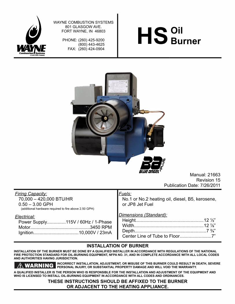
HSOilBurner
Manual: 21663Revision 15
Publication Date: 7/26/2011
Firing Capacity:70,000 – 420,000 BTU/HR0.50 – 3.00 GPH
(additional hardware required to fire above 2.50 GPH)
Electrical:Power Supply..............115V / 60Hz / 1-PhaseMotor...............................................3450 RPMIgnition...................................10,000V / 23mA
Fuels:No.1 or No.2 heating oil, diesel, B5, kerosene, or JP8 Jet Fuel
Dimensions (Standard):Height.....................................................12 ½”Width......................................................12 ⅞”Depth........................................................7 ¾”Center Line of Tube to Floor.........................7”
INSTALLATION OF BURNERINSTALLATION OF THE BURNER MUST BE DONE BY A QUALIFIED INSTALLER IN ACCORDANCE WITH REGULATIONS OF THE NATIONAL FIRE PROTECTION STANDARD FOR OIL-BURNING EQUIPMENT, NFPA NO. 31, AND IN COMPLETE ACCORDANCE WITH ALL LOCAL CODES AND AUTHORITIES HAVING JURISDICTION.
INCORRECT INSTALLATION, ADJUSTMENT, OR MISUSE OF THIS BURNER COULD RESULT IN DEATH, SEVERE PERSONAL INJURY, OR SUBSTANTIAL PROPERTY DAMAGE AND WILL VOID THE WARRANTY.
A QUALIFIED INSTALLER IS THE PERSON WHO IS RESPONSIBLE FOR THE INSTALLATION AND ADJUSTMENT OF THE EQUIPMENT AND WHO IS LICENSED TO INSTALL OIL-BURNING EQUIPMENT IN ACCORDANCE WITH ALL CODES AND ORDINANCES.
THESE INSTRUCTIONS SHOULD BE AFFIXED TO THE BURNEROR ADJACENT TO THE HEATING APPLIANCE.
Burner / Appliance Service LogService Date Contractor License # Actions Performed
/ / / / / / / / / / / / / / / / / / / / / / / / / / / / / / / / / / / / / / / / / / / / / / / / / / / / / / / / / / / / / / / /
Table of Contents
GENERAL INFORMATIONTO THE HOMEOWNER................................................................................................................................................... 1HAZARD DEFINITIONS................................................................................................................................................... 1GENERAL SPECIFCATIONS........................................................................................................................................... 1APPROVALS.................................................................................................................................................................... 1
PREPARE INSTALLATION SITEGENERAL INFORMATION............................................................................................................................................... 2COMBUSTION CHAMBER.............................................................................................................................................. 2FUEL PUMPS................................................................................................................................................................... 3FUEL LINES..................................................................................................................................................................... 3FUEL TANKS.................................................................................................................................................................... 3AIR SUPPLY FOR COMBUSTION................................................................................................................................... 3CHIMNEY......................................................................................................................................................................... 3DRAFT REGULATORS.................................................................................................................................................... 3
PREPARE BURNERGUN ASSEMBLY REMOVAL........................................................................................................................................... 4NOZZLE INSTALLATION................................................................................................................................................. 4CHECK AND ADJUST ELECTRODE SETTINGS............................................................................................................4GUN ASSEMBLY INSTALLATION.................................................................................................................................... 5CALIBRATE AIR CONE POSITION.................................................................................................................................. 6WIRING............................................................................................................................................................................ 6
STARTING PROCEDURESTARTING BURNER........................................................................................................................................................ 7FINAL ADJUSTMENTS.................................................................................................................................................... 7SETTING COMBUSTION EFFICIENCY.......................................................................................................................... 8FINAL CHECKS............................................................................................................................................................... 8
BURNER MAINTENANCESCHEDULED MAINTENANCE........................................................................................................................................ 9BLOWER WHEEL REPLACEMENT................................................................................................................................. 9SUNTEC PUMP INSTALLATION INFORMATION............................................................................................................9NOZZLE SELECTION.................................................................................................................................................... 12OIL PRIMARY SPECIFICATIONS.................................................................................................................................. 13BURNER REPLACEMENT PARTS – MODEL HS.........................................................................................................16WAYNE® FUEL BLEND................................................................................................................................................. 17
MISCELLANEOUSLIMITED WARRANTY.................................................................................................................................................... 18NOTES........................................................................................................................................................................... 19
GENERAL INFORMATION
TO THE HOMEOWNERSince 1928, Wayne has supplied the Homeowners of the world with high quality oil burners. You are obtaining a superior burner unsurpassed in engineering design and product development. If properly installed and serviced, it will provide you with many years of efficient, trouble-free operation. Please read this manual carefully.
Wayne warrants its burner specifically to those who have purchased it for resale, including your dealer. If, in any case, you have a problem with your burner, or its installation, you should contact your dealer for assistance.
Wayne recommends yearly inspection/service of your oil heating system by a qualified service agency or individual.
A qualified service agency or individual must be:
• Licensed or certified to install and provide technical service to oil heating systems.
• Experienced with all applicable codes, standards and ordinances.
• Responsible for the correct installation and commission of the equipment.
• Skilled in the adjustment of oil burners using combustion test instruments.
ELECTRIC SHOCK HAZARDHigh voltages are present in
this equipment. Follow these rules to avoid electrical shock: - Use only a properly grounded circuit. A ground fault interrupter is recommended. - Do not spray water directly on burner. - Turn off power before servicing. - Read owner's manual before using
OVERHEATING HAZARDShould overheating occur:
1. Shut off the manual oil valve to the appliance. 2. Do NOT shut off the control switch to the pump or blower.
NEVER ATTEMPT TO USE GASOLINE AS A FUEL FOR
THIS BURNER, AS IT IS MORE COMBUSTIBLE AND COULD RESULT IN A SERIOUS EXPLOSION.
Incorrect installation, adjustment or use of the
burner could result in severe personal injury death or substantial property damage from fire, carbon monoxide poisoning, soot or explosion.
Do not store or use gasoline or other flammable vapors and
liquids in the vicinity of this or any other appliance.
HAZARD DEFINITIONSIndicates an imminently hazardous situation, which, if not avoided, will
result in death, serious injury, or property damage.
Indicates a potentially hazardous situation, which, if not avoided,
could result in death, severe personal injury, or substantial property damage.
Indicates a potentially hazardous situation, which, if not avoided,
may result in personal injury or property damage.
Intended to bring special attention to information, but not related to
personal injury or property damage.
GENERAL SPECIFCATIONS
Firing Rate: 0.50 – 3.00 GPH*70,000 – 420,000 BTU/HR
Fuels:
No. 1 or No. 2 heating oil, diesel, B5, kerosene, or JP8 Jet Fuel ONLY -NEVER burn garbage or refuse in the unit -NEVER try to ignite oil by tossing burning material into the heating unit -NEVER burn waste or crankcase oil
Electrical:
Power Supply115V / 60Hz / 1PH
Motor3450 RPM, N.E.M.A. Flange, Auto Overload Protection
Ignitior10,000V / 23mA secondary, Continuous Duty-Shielded Interrupted
Fuel Pump: Suntec
Mounting: Rigid Flange, Adjustable Flange, or Base Mount
Dimensions:
Height..................................................12 ½”Width...................................................12 ⅞”Depth.....................................................7 ¾”Center Line of tube to Floor.......................7”
* To fire over 2.50 GPH, additional hardware is required. See “Burner Replacement Parts” for details
APPROVALSThis burner complies with ANSI/UL Standard 296 and is for use with, No. 1 fuel oil, No. 2 fuel oil, or B5 blend. State and local approvals are shown on burner rating label. All burners should be installed in accordance with the National Fire Protection Association, and in complete accordance with all local codes and authorities having jurisdiction. Regulation of these authorities takes precedence over the general instructions provided in this manual.
1

PREPARE INSTALLATION SITE
GENERAL INFORMATIONWhen installing the appliance and/or burner, be sure to provide adequate space for easy service and maintenance.
Prior to installation of the oil burner, the heating system should be carefully inspected for defects and cleanliness. The flue passages and heat absorbing surfaces must be clean to ensure maximum heat transfer. Soot acts as an insulator, which retards the transfer of heat.
The combustion chamber, flue gas passages, and all doors and openings must be tightly sealed to eliminate air infiltration. Excess air decreases CO2 levels and thus lowers efficiency. Inspect the flue and chimney for leaks and obstructions.
Be sure the chimney is of adequate size and height. Install a draft regulator the same size as the flue pipe (see page 3 under Chimneys and Draft Regulators).
Figure 1: Overall Burner Dimensions
COMBUSTION CHAMBERThe purpose of a combustion chamber is to maintain a high flame temperature by reflecting the heat back into the flame. A high temperature ensures greater combustion efficiency and lower stack losses. An insulating refractory or a Fiber Fax type chamber can be used with this burner.
Caution should be taken when installing Flamelock™ burners in
stainless steel combustion chambers, because of the higher temperature levels produced by high performance flame retention burners. The temperature may exceed the temperature ratings of the stainless steel chamber and can result in chamber burnouts.
It is important to select and install, if necessary, the correct size chamber on a conversion job. (Suggested chamber dimensions are shown in Table 1.) On the Flamelock™ conversion burners, the atomized oil burns just off the Flamelock™ cone. On all oil burners, the atomized oil must not touch the sides or bottom of chamber, or smoke will result (see Figure 21, page 13). Install the burner so the face of the air cone of burner is set 1/4” behind the inside face of the chamber (See Figure 2).
To eliminate the smoke, excess air will be required, resulting in high stack temperature and lower combustion efficiency.
When you are replacing a standard burner with a flame retention burner, take the following precautions:
1. Use pliable ceramic liner to line the inside of chamber.2. Adjust burner (see “Final Adjustments” on page 7).
Table 1: Suggested Combustion Chamber Dimensions
Conversion or UpgradingChamber Dimensions (in inches)
Firing Rate
(GPH)
Square Chamber
Diameter Round
ChamberHeight Nozzle to
Floor
0.50 7 x 7 8 11 5 – 60.75 8 x 8 9 12 5 – 60.85 8½ x 8½ 9 12 5 – 61.00 9 x 9 10⅛ 12½ 5 – 61.25 10 x 10 11¼ 12½ 5 – 61.35 10½ x 10½ 11¾ 12¾ 5 – 61.50 11 x 11 12⅜ 13 5 – 61.65 11½ x 11½ 13 13¾ 5 – 62.00 12⅝ x 12⅝ 14¼ 13¾ 6 – 72.50 14¼ x 14¼ 16 14 7 – 83.00 15½ x 15½ 17½ 15 7 – 8
The “Air Tube Length” is the distance from the front of the aluminum fan housing to the face of the Air Cone.
The maximum insertion depth of any given air tube is reduced by
the thickness of the adjustable flange. Example: A 6” air tube can only be inserted about 5”.
2
Figure 2: Combustion Chamber Detail
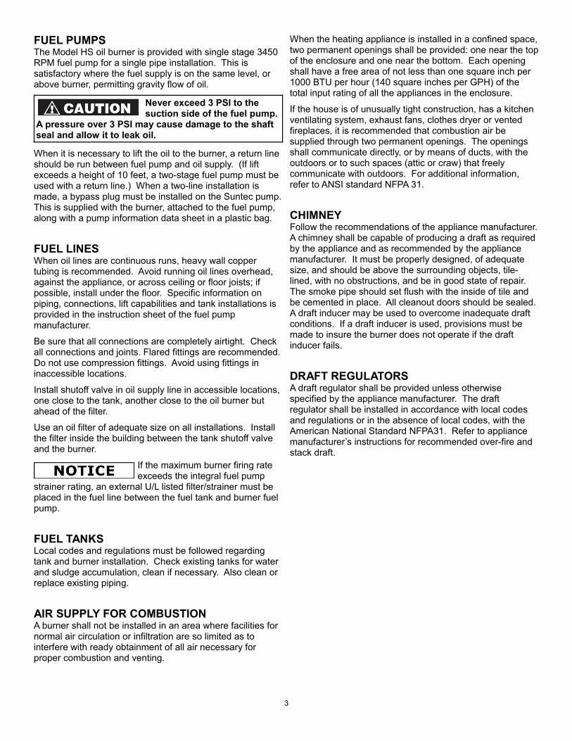
FUEL PUMPSThe Model HS oil burner is provided with single stage 3450 RPM fuel pump for a single pipe installation. This is satisfactory where the fuel supply is on the same level, or above burner, permitting gravity flow of oil.
Never exceed 3 PSI to the suction side of the fuel pump.
A pressure over 3 PSI may cause damage to the shaft seal and allow it to leak oil.
When it is necessary to lift the oil to the burner, a return line should be run between fuel pump and oil supply. (If lift exceeds a height of 10 feet, a two-stage fuel pump must be used with a return line.) When a two-line installation is made, a bypass plug must be installed on the Suntec pump. This is supplied with the burner, attached to the fuel pump, along with a pump information data sheet in a plastic bag.
FUEL LINESWhen oil lines are continuous runs, heavy wall copper tubing is recommended. Avoid running oil lines overhead, against the appliance, or across ceiling or floor joists; if possible, install under the floor. Specific information on piping, connections, lift capabilities and tank installations is provided in the instruction sheet of the fuel pump manufacturer.
Be sure that all connections are completely airtight. Check all connections and joints. Flared fittings are recommended. Do not use compression fittings. Avoid using fittings in inaccessible locations.
Install shutoff valve in oil supply line in accessible locations, one close to the tank, another close to the oil burner but ahead of the filter.
Use an oil filter of adequate size on all installations. Install the filter inside the building between the tank shutoff valve and the burner.
If the maximum burner firing rate exceeds the integral fuel pump
strainer rating, an external U/L listed filter/strainer must be placed in the fuel line between the fuel tank and burner fuel pump.
FUEL TANKSLocal codes and regulations must be followed regarding tank and burner installation. Check existing tanks for water and sludge accumulation, clean if necessary. Also clean or replace existing piping.
AIR SUPPLY FOR COMBUSTIONA burner shall not be installed in an area where facilities for normal air circulation or infiltration are so limited as to interfere with ready obtainment of all air necessary for proper combustion and venting.
When the heating appliance is installed in a confined space, two permanent openings shall be provided: one near the top of the enclosure and one near the bottom. Each opening shall have a free area of not less than one square inch per 1000 BTU per hour (140 square inches per GPH) of the total input rating of all the appliances in the enclosure.
If the house is of unusually tight construction, has a kitchen ventilating system, exhaust fans, clothes dryer or vented fireplaces, it is recommended that combustion air be supplied through two permanent openings. The openings shall communicate directly, or by means of ducts, with the outdoors or to such spaces (attic or craw) that freely communicate with outdoors. For additional information, refer to ANSI standard NFPA 31.
CHIMNEYFollow the recommendations of the appliance manufacturer. A chimney shall be capable of producing a draft as required by the appliance and as recommended by the appliance manufacturer. It must be properly designed, of adequate size, and should be above the surrounding objects, tile-lined, with no obstructions, and be in good state of repair. The smoke pipe should set flush with the inside of tile and be cemented in place. All cleanout doors should be sealed. A draft inducer may be used to overcome inadequate draft conditions. If a draft inducer is used, provisions must be made to insure the burner does not operate if the draft inducer fails.
DRAFT REGULATORSA draft regulator shall be provided unless otherwise specified by the appliance manufacturer. The draft regulator shall be installed in accordance with local codes and regulations or in the absence of local codes, with the American National Standard NFPA31. Refer to appliance manufacturer’s instructions for recommended over-fire and stack draft.
3
PREPARE BURNER
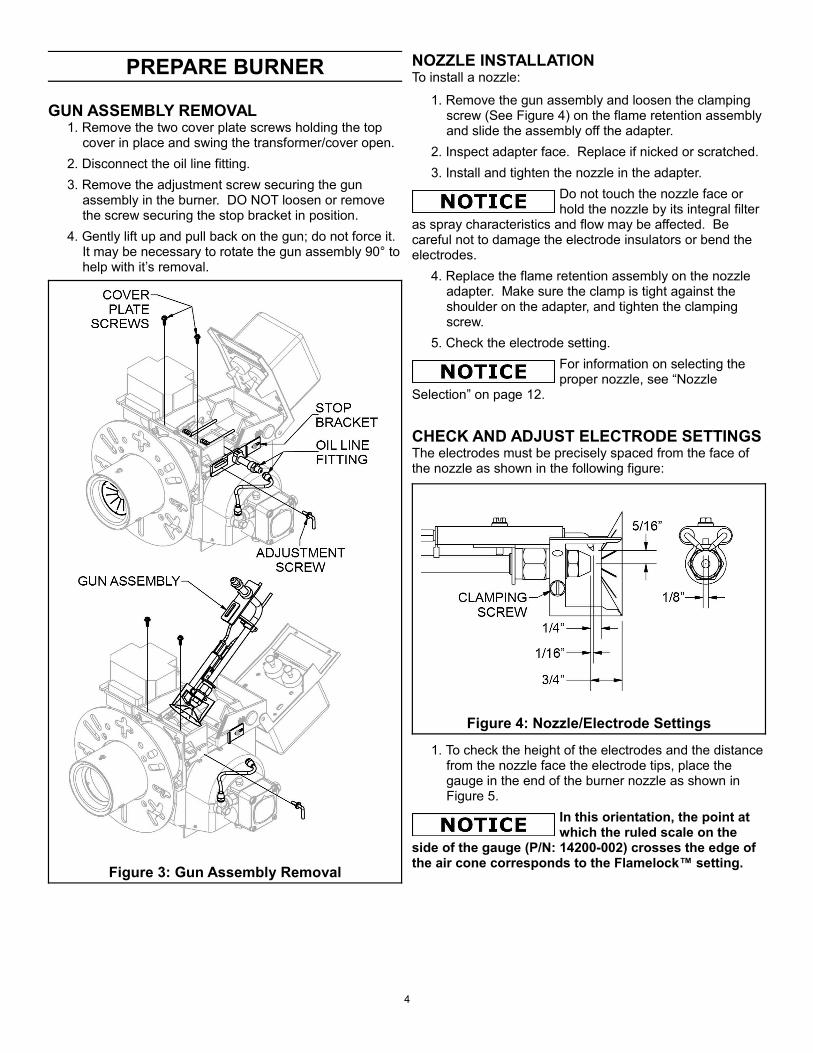
GUN ASSEMBLY REMOVAL1. Remove the two cover plate screws holding the top
cover in place and swing the transformer/cover open.2. Disconnect the oil line fitting.3. Remove the adjustment screw securing the gun
assembly in the burner. DO NOT loosen or remove the screw securing the stop bracket in position.
4. Gently lift up and pull back on the gun; do not force it. It may be necessary to rotate the gun assembly 90° to help with it’s removal.
NOZZLE INSTALLATIONTo install a nozzle:
1. Remove the gun assembly and loosen the clamping screw (See Figure 4) on the flame retention assembly and slide the assembly off the adapter.
2. Inspect adapter face. Replace if nicked or scratched.3. Install and tighten the nozzle in the adapter.
Do not touch the nozzle face or hold the nozzle by its integral filter
as spray characteristics and flow may be affected. Be careful not to damage the electrode insulators or bend the electrodes.
4. Replace the flame retention assembly on the nozzle adapter. Make sure the clamp is tight against the shoulder on the adapter, and tighten the clamping screw.
5. Check the electrode setting.For information on selecting the proper nozzle, see “Nozzle
Selection” on page 12.
CHECK AND ADJUST ELECTRODE SETTINGSThe electrodes must be precisely spaced from the face of the nozzle as shown in the following figure:
Figure 4: Nozzle/Electrode Settings
1. To check the height of the electrodes and the distance from the nozzle face the electrode tips, place the gauge in the end of the burner nozzle as shown in Figure 5.
In this orientation, the point at which the ruled scale on the
side of the gauge (P/N: 14200-002) crosses the edge of the air cone corresponds to the Flamelock™ setting.
4
Figure 3: Gun Assembly Removal
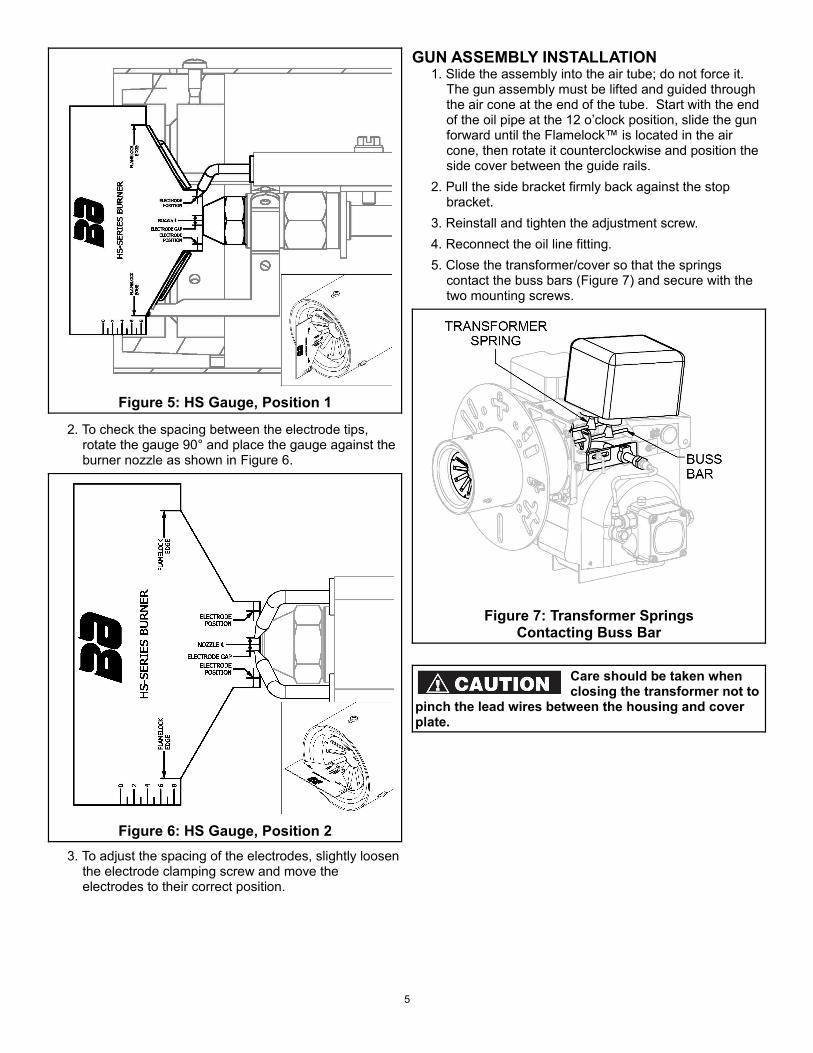
Figure 5: HS Gauge, Position 1
2. To check the spacing between the electrode tips, rotate the gauge 90° and place the gauge against the burner nozzle as shown in Figure 6.
Figure 6: HS Gauge, Position 23. To adjust the spacing of the electrodes, slightly loosen
the electrode clamping screw and move the electrodes to their correct position.
GUN ASSEMBLY INSTALLATION1. Slide the assembly into the air tube; do not force it.
The gun assembly must be lifted and guided through the air cone at the end of the tube. Start with the end of the oil pipe at the 12 o’clock position, slide the gun forward until the Flamelock™ is located in the air cone, then rotate it counterclockwise and position the side cover between the guide rails.
2. Pull the side bracket firmly back against the stop bracket.
3. Reinstall and tighten the adjustment screw.4. Reconnect the oil line fitting.5. Close the transformer/cover so that the springs
contact the buss bars (Figure 7) and secure with the two mounting screws.
Figure 7: Transformer SpringsContacting Buss Bar
Care should be taken when closing the transformer not to
pinch the lead wires between the housing and cover plate.
5

CALIBRATE AIR CONE POSITIONIf any components have been replaced on a given gun assembly, it may be necessary to calibrate the air cone position. As long as the stop bracket is not loosened or removed, this procedure is not necessary during normal maintenance.
1. Loosen the stop bracket, pull it back to the zero position, and re-tighten the bracket as indicated in Figure 8.
Figure 8: Stop Bracket2. Loosen the gun adjustment screw, slide the gun
assembly back until it is flat against the stop bracket, and re-tighten the adjustment screw.
3. At this point, the Flamelock™ cone should be flush with the stepped face of the air cone (See Figure 13, page 7). If it is not flush, loosen the 3 screws securing the air cone in place.
Figure 9: Air Cone Mounting Screws4. Adjust the air cone to be flush with the Flamelock™
cone and tighten the 3 air cone screws.5. After completing this calibration, it will be necessary to
re-tune burner and check combustion.
WIRINGAll wiring must comply with the National Electric Code and local ordinances. Refer to diagram supplied with burner or controls, making sure the burner and controls are wired correctly and that the line switch is properly connected to a 20 amp fused service.
To use with line voltage thermostat, jumper terminals T-T
and add thermostat as shown at (1) in series with limit control.
Figure 10: Intermittent Ignition Wiring
Figure 11: Interrupted Ignition Wiring
6
STARTING PROCEDURE
STARTING BURNER1. Be sure main switch is in “OFF” position, thermostat is
substantially above room temperature, the oil tank is filled, all valves are open, and controls set for operation.
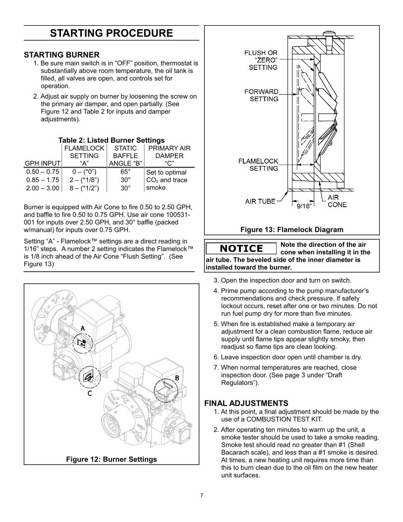
2. Adjust air supply on burner by loosening the screw on the primary air damper, and open partially. (See Figure 12 and Table 2 for inputs and damper adjustments).
Table 2: Listed Burner Settings
GPH INPUT
FLAMELOCK SETTING
“A”
STATIC BAFFLE
ANGLE “B”
PRIMARY AIR DAMPER
“C”0.50 – 0.75 0 – (*0”) 65° Set to optimal
CO2 and trace smoke.
0.85 – 1.75 2 – (*1/8”) 30°2.00 – 3.00 8 – (*1/2”) 30°
Burner is equipped with Air Cone to fire 0.50 to 2.50 GPH, and baffle to fire 0.50 to 0.75 GPH. Use air cone 100531-001 for inputs over 2.50 GPH, and 30° baffle (packed w/manual) for inputs over 0.75 GPH.
Setting “A” - Flamelock™ settings are a direct reading in 1/16” steps. A number 2 setting indicates the Flamelock™ is 1/8 inch ahead of the Air Cone “Flush Setting”. (See Figure 13)
Figure 12: Burner Settings
Figure 13: Flamelock Diagram
Note the direction of the air cone when installing it in the
air tube. The beveled side of the inner diameter is installed toward the burner.
3. Open the inspection door and turn on switch.4. Prime pump according to the pump manufacturer’s
recommendations and check pressure. If safety lockout occurs, reset after one or two minutes. Do not run fuel pump dry for more than five minutes.
5. When fire is established make a temporary air adjustment for a clean combustion flame, reduce air supply until flame tips appear slightly smoky, then readjust so flame tips are clean looking.
6. Leave inspection door open until chamber is dry. 7. When normal temperatures are reached, close
inspection door. (See page 3 under “Draft Regulators”).
FINAL ADJUSTMENTS1. At this point, a final adjustment should be made by the
use of a COMBUSTION TEST KIT.2. After operating ten minutes to warm up the unit, a
smoke tester should be used to take a smoke reading. Smoke test should read no greater than #1 (Shell Bacarach scale), and less than a #1 smoke is desired. At times, a new heating unit requires more time than this to burn clean due to the oil film on the new heater unit surfaces.
7
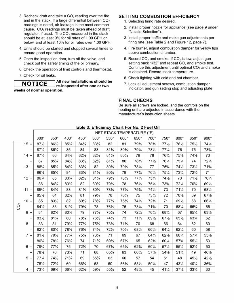
3. Recheck draft and take a CO2 reading over the fire and in the stack. If a large differential between CO2
readings is noted, air leakage is the most common cause. CO2 readings must be taken ahead of draft regulator, if used. The CO2 measured in the stack should be at least 9% for oil rates of 1.00 GPH or below, and at least 10% for oil rates over 1.00 GPH.
4. Units should be started and stopped several times to ensure good operation.
5. Open the inspection door, turn off the valve, and check out the safety timing of the oil primary.
6. Check the operation of limit controls and thermostat.7. Check for oil leaks.
All new installations should be re-inspected after one or two
weeks of normal operation.
SETTING COMBUSTION EFFICIENCY1. Selecting firing rate desired.2. Install proper nozzle for appliance (see page 9 under
“Nozzle Selection”).3. Install proper baffle and make gun adjustments per
firing rate (see Table 2 and Figure 12, page 7).4. Fire burner, adjust combustion damper for yellow tips
above combustion chamber.5. Record CO2 and smoke. If CO2 is low, adjust gun
setting back 1/32” and repeat CO2 and smoke test. Continue this adjustment until optimal CO2 and smoke is obtained. Record stack temperature.
6. Check lighting with cold and hot chamber.7. Lock all adjustment screws, combustion damper
indicator, and gun setting stop and adjusting plate.
FINAL CHECKSBe sure all screws are locked, and the controls on the heating unit are adjusted in accordance with the manufacturer’s instruction sheets.
Table 3: Efficiency Chart For No. 2 Fuel OilNET STACK TEMPERATURE (°F)
300° 350° 400° 450° 500° 550° 600° 650° 700° 750° 800° 850° 900°
CO
2
15 87½ 86½ 85¼ 84¼ 83¼ 82 81 79¾ 78¾ 77½ 76½ 75½ 74¼ 87½ 86¼ 85 84 83 81¾ 80¾ 79¼ 78½ 77¼ 76 75 73¾
14 87¼ 86 84¾ 82¾ 82¾ 81½ 80¼ 79 78 76¾ 75½ 74½ 73 87 85¾ 84½ 83½ 82½ 81¼ 80 78¾ 77½ 76¼ 75¼ 74 72¼
13 86¾ 85½ 84¼ 83¼ 82 80¾ 79½ 78¼ 77 75¾ 74½ 73½ 71¾ 86½ 85¼ 84 83¼ 81½ 80¼ 79 77¾ 76½ 75¼ 73¾ 72¾ 71
12 86¼ 85 83¾ 82½ 81¼ 79¾ 78½ 77¼ 75¾ 74½ 73 71½ 70¼ 86 84¾ 83½ 82 80¾ 79¼ 78 76½ 75¼ 73¾ 72¼ 70¾ 69½
11 85¾ 84½ 83 81½ 80¼ 78¾ 77¼ 75¾ 74½ 73 71½ 70 68½ 85½ 84 82½ 81 79½ 78 76½ 75 73¾ 72 70½ 69 67½
10 85 83½ 82 80½ 78¾ 77¼ 75¾ 74¼ 72¾ 71 69½ 68 66¼ 84½ 83 81½ 79¾ 78 76½ 75 73¼ 71¾ 70 68¼ 66¾ 65
9 84 82¼ 80¾ 79 77¼ 75¾ 74 72¼ 70¾ 68¾ 67 65¼ 63½ 83½ 81¾ 80 78¼ 76½ 74¾ 73 71¼ 69½ 67½ 65½ 63¾ 62
8 83 81 79¼ 77½ 75½ 73¾ 71¾ 70 68 66 64 62 60 82¼ 80¼ 78½ 76½ 74½ 72½ 70½ 68½ 66½ 64¼ 62¼ 60 58
7 81½ 79½ 77¼ 75¼ 73¼ 71 69 67 64¾ 62½ 60¼ 57¾ 55½ 80¾ 78½ 76¼ 74 71¾ 69½ 67¼ 65 62¾ 60¼ 57¾ 55½ 53
6 79¾ 77¼ 75 72½ 70 67¾ 65¼ 62¾ 60¼ 57½ 55½ 52½ 50 78½ 76 73½ 71 68 65½ 63 60¼ 57½ 54½ 51¾ 49 46½
5 77¼ 74½ 71¾ 69 65¾ 63 60 57 54 51 48 45½ 42½ 75½ 72½ 69 66¼ 63 60 56¾ 53½ 50¼ 47 43½ 40¼ 36¾
4 73¼ 69¾ 66¼ 62¾ 59¼ 55¾ 52 48½ 45 41¼ 37½ 33¾ 30
8

BURNER MAINTENANCE
SCHEDULED MAINTENANCEOILING MOTORProper lubrication of the motor will prolong its service life. Oil sleeve bearing motors with 6 drops of SAE 20 oil once a year. DO NOT OVER OIL. Ball-bearing motors do not require oiling under normal service conditions. The bearing type is printed on the motor nameplate.
FILTERThe oil filter cartridge should be replaced once a year so the fuel oil will not become contaminated and plug up fuel pump and nozzle of oil burner.
NOZZLEThe nozzle should be changed at least once a year before the start-up of the heating season. Replace with proper nozzle.
Do not touch filter or touch face of nozzle during handling. This could
foil the filter or impact the spray pattern due to contamination.
FAN & BLOWER HOUSINGThis must be kept clean, free of dirt and lint. Open the transformer and off cycle damper to check fan blades from above.
ELECTRODE SETTINGSThis is very important for reliable ignition of the oil; check these once a year in accordance with the instructions provided in this manual. Replace electrodes if worn excessively or if porcelain insulator is oil soaked or cracked.
Be sure the electric power is off burner when the
transformer/cover is opened up for this inspection.
OTHER COMPONENTSIf for any reason any of the burner parts must be replaced, always use parts recommended by the manufacturer. Specify part number and item description when ordering.
In all communications, state burner model and serial
numbers. Go to www.waynecombustion.com and enter the complete specification number in the “Product Search” box to generate a parts list for your specific burner.
BLOWER WHEEL REPLACEMENTIf the blower wheel or motor is ever replaced or removed, the spacing between the blower and the motor must be checked to ensure proper burner function.
The proper spacing is 9/64” (or 0.140”) between the fan and the motor face. This is slightly more than 1/8”.
Figure 14: Fan Setting
SUNTEC PUMP INSTALLATION INFORMATIONGENERAL INFORMATIONLong or oversized inlet lines may require the pump to operate dry during initial bleeding period. In such cases, the priming may be assisted by injecting fuel oil into the pump gearset. Under lift conditions, lines and fittings must be air tight. To assure this, "Pipe Dope" may be applied to both the used and unused inlet, and both return fittings.
Do not use Teflon tape or compression fittings!
MOUNTING POSITIONModel “A” Single Stage Fuel Pump may be mounted in any position. Model "B" Two Stage Fuel Pump may be mounted in any position except upside down (1/8” ports pointed down).
VACUUM CHECKIn single pipe installations , a Vacuum Gage may be installed in either of the 1/4” inlet ports or in the 1/8" return port, whichever is most convenient. The Model “A" pump should be used where the vacuum does not exceed 6" Hg. single pipe and 12" Hg. two pipe. The Model "B" pump should be used where vacuum does not exceed 17" Hg.
Remember, running vacuum is the total of all pressure drops (ΔP) in the system from the tank to the inlet of the pump.
9
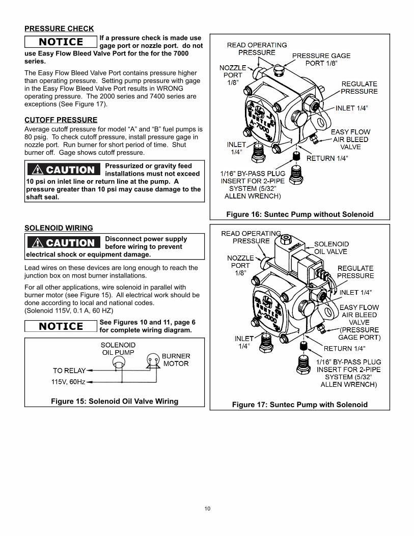
PRESSURE CHECKIf a pressure check is made use gage port or nozzle port. do not
use Easy Flow Bleed Valve Port for the for the 7000 series.The Easy Flow Bleed Valve Port contains pressure higher than operating pressure. Setting pump pressure with gage in the Easy Flow Bleed Valve Port results in WRONG operating pressure. The 2000 series and 7400 series are exceptions (See Figure 17).
CUTOFF PRESSUREAverage cutoff pressure for model “A” and “B” fuel pumps is 80 psig. To check cutoff pressure, install pressure gage in nozzle port. Run burner for short period of time. Shut burner off. Gage shows cutoff pressure.
Pressurized or gravity feed installations must not exceed
10 psi on inlet line or return line at the pump. A pressure greater than 10 psi may cause damage to the shaft seal.
SOLENOID WIRINGDisconnect power supply before wiring to prevent
electrical shock or equipment damage.
Lead wires on these devices are long enough to reach the junction box on most burner installations.
For all other applications, wire solenoid in parallel with burner motor (see Figure 15). All electrical work should be done according to local and national codes.(Solenoid 115V, 0.1 A, 60 HZ)
See Figures 10 and 11, page 6 for complete wiring diagram.
Figure 15: Solenoid Oil Valve Wiring
Figure 16: Suntec Pump without Solenoid
Figure 17: Suntec Pump with Solenoid
10

ONE-PIPE SYSTEM – MODEL ADo not install bypass plug! Connect inlet line to pump inlet. Start burner. Arrange primary burner control for continuous operation during purging. Open easy flow bleed valve 1 turn CCW. Bleed pump until all air bubbles disappear. Tighten Easy Flow Bleed Valve securely.
Hurried bleeding will impair efficient operation of pump.
Figure 18: One Pipe System Diagram(Model A)
The SUNTEC MODEL “A" FUEL PUMP may be installed ONE-PIPE with Gravity Feed or Lift. The maximum allowable lift is 8 ft. (See Figure 18).
One-pipe installations must be absolutely air tight, otherwise,
leaks or loss of prime may result. Bleed line and fuel pump completely. Bleed for 15 seconds after last air is seen from Easy Flow to be certain lines are air free.
3/8” line L=6−0.75 H0.0086Q 1/2” line L= 6−0.75H
0.00218 Q
L = line length in feetH = head in feetQ = firing rate in GPH
If tank is above pump, change - to +. Fittings, valves, and filters will reduce total length allowed.
TWO-PIPE SYSTEM – MODEL A & BRemove 1/16" bypass plug from plastic bag attached to pump. Remove 1/4" plug from return port. Insert bypass plug (See Figure 16 or Figure 17). Attach return and inlet lines. Start burner (air bleeding is automatic). Opening Easy Flow Air Bleed Valve will allow a faster bleed, if desired. Return line must terminate 3” to 4" above supply line inlet (see Figure 19). Failure to do this may introduce air into the system and could result in the loss of prime.
Always terminate return line as shown in Figure 19. Line lengths include both vertical and horizontal lengths.
Figure 19: Two Pipe System Diagram(Models A & B)
Table 4: Single Stage, Two-PipeMaximum Line Length (H + R)
Lift “H”(Figure
19)
1725 RPM 3450 RPM3/8” OD Tubing
1/2” OD Tubing
3/8” ODTubing
1/2” ODTubing
3GPH 3GPH 3GPH 7GPH 3GPH 7GPH0' 86' 100' 84' 71' 100' 100'1' 80' 100' 78' 66' 100' 100'2' 75' 100' 73' 62' 100' 100'3' 70' 100' 68' 57' 100' 100'4' 64' 100' 63' 53' 100' 100'5' 59' 100' 57' 48' 100' 100'6' 54' 100' 52' 44' 100' 100'7' 49' 100' 47' 39' 100' 100'8' 43' 100' 42' 35' 100' 100'9' 37' 100' 36' 31' 100' 100'
10' 32' 100' 31' 27' 100' 100'11' 26' 100' 26' 22' 100' 87'12' 21' 85' 21' 18' 83' 70'13' - 63' - - 62' 52'14' - 42' - - 41' 35'
11
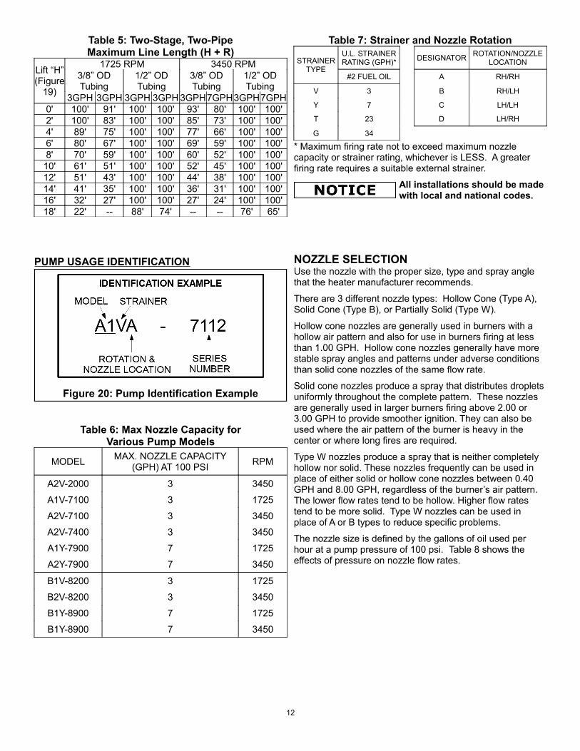
Table 5: Two-Stage, Two-PipeMaximum Line Length (H + R)
Lift “H”(Figure
19)
1725 RPM 3450 RPM3/8” OD Tubing
1/2” OD Tubing
3/8” ODTubing
1/2” ODTubing
3GPH 3GPH 3GPH 3GPH 3GPH7GPH3GPH7GPH0' 100' 91' 100' 100' 93' 80' 100' 100'2' 100' 83' 100' 100' 85' 73' 100' 100'4' 89' 75' 100' 100' 77' 66' 100' 100'6' 80' 67' 100' 100' 69' 59' 100' 100'8' 70' 59' 100' 100' 60' 52' 100' 100'
10' 61' 51' 100' 100' 52' 45' 100' 100'12' 51' 43' 100' 100' 44' 38' 100' 100'14' 41' 35' 100' 100' 36' 31' 100' 100'16' 32' 27' 100' 100' 27' 24' 100' 100'18' 22' -- 88' 74' -- -- 76' 65'
PUMP USAGE IDENTIFICATION
Figure 20: Pump Identification Example
Table 6: Max Nozzle Capacity forVarious Pump Models
MODEL MAX. NOZZLE CAPACITY (GPH) AT 100 PSI RPM
A2V-2000 3 3450
A1V-7100 3 1725
A2V-7100 3 3450
A2V-7400 3 3450
A1Y-7900 7 1725
A2Y-7900 7 3450
B1V-8200 3 1725
B2V-8200 3 3450
B1Y-8900 7 1725
B1Y-8900 7 3450
Table 7: Strainer and Nozzle Rotation
STRAINER TYPE
U.L. STRAINER RATING (GPH)* DESIGNATOR ROTATION/NOZZLE
LOCATION
#2 FUEL OIL A RH/RH
V 3 B RH/LH
Y 7 C LH/LH
T 23 D LH/RH
G 34
* Maximum firing rate not to exceed maximum nozzle capacity or strainer rating, whichever is LESS. A greater firing rate requires a suitable external strainer.
All installations should be made with local and national codes.
NOZZLE SELECTIONUse the nozzle with the proper size, type and spray angle that the heater manufacturer recommends.
There are 3 different nozzle types: Hollow Cone (Type A), Solid Cone (Type B), or Partially Solid (Type W).
Hollow cone nozzles are generally used in burners with a hollow air pattern and also for use in burners firing at less than 1.00 GPH. Hollow cone nozzles generally have more stable spray angles and patterns under adverse conditions than solid cone nozzles of the same flow rate.
Solid cone nozzles produce a spray that distributes droplets uniformly throughout the complete pattern. These nozzles are generally used in larger burners firing above 2.00 or 3.00 GPH to provide smoother ignition. They can also be used where the air pattern of the burner is heavy in the center or where long fires are required.
Type W nozzles produce a spray that is neither completely hollow nor solid. These nozzles frequently can be used in place of either solid or hollow cone nozzles between 0.40 GPH and 8.00 GPH, regardless of the burner’s air pattern. The lower flow rates tend to be hollow. Higher flow rates tend to be more solid. Type W nozzles can be used in place of A or B types to reduce specific problems.
The nozzle size is defined by the gallons of oil used per hour at a pump pressure of 100 psi. Table 8 shows the effects of pressure on nozzle flow rates.
12
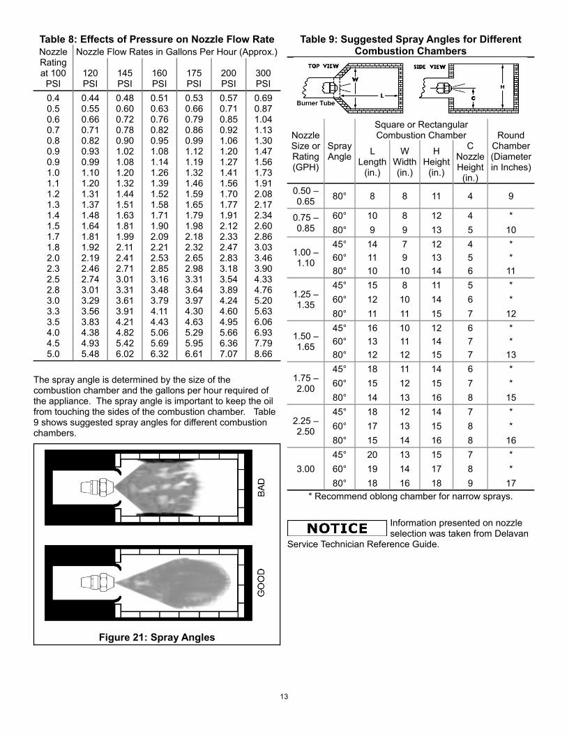
Table 8: Effects of Pressure on Nozzle Flow RateNozzle Rating at 100
PSI
Nozzle Flow Rates in Gallons Per Hour (Approx.)
120PSI
145PSI
160PSI
175PSI
200PSI
300PSI
0.4 0.44 0.48 0.51 0.53 0.57 0.690.5 0.55 0.60 0.63 0.66 0.71 0.870.6 0.66 0.72 0.76 0.79 0.85 1.040.7 0.71 0.78 0.82 0.86 0.92 1.130.8 0.82 0.90 0.95 0.99 1.06 1.300.9 0.93 1.02 1.08 1.12 1.20 1.470.9 0.99 1.08 1.14 1.19 1.27 1.561.0 1.10 1.20 1.26 1.32 1.41 1.731.1 1.20 1.32 1.39 1.46 1.56 1.911.2 1.31 1.44 1.52 1.59 1.70 2.081.3 1.37 1.51 1.58 1.65 1.77 2.171.4 1.48 1.63 1.71 1.79 1.91 2.341.5 1.64 1.81 1.90 1.98 2.12 2.601.7 1.81 1.99 2.09 2.18 2.33 2.861.8 1.92 2.11 2.21 2.32 2.47 3.032.0 2.19 2.41 2.53 2.65 2.83 3.462.3 2.46 2.71 2.85 2.98 3.18 3.902.5 2.74 3.01 3.16 3.31 3.54 4.332.8 3.01 3.31 3.48 3.64 3.89 4.763.0 3.29 3.61 3.79 3.97 4.24 5.203.3 3.56 3.91 4.11 4.30 4.60 5.633.5 3.83 4.21 4.43 4.63 4.95 6.064.0 4.38 4.82 5.06 5.29 5.66 6.934.5 4.93 5.42 5.69 5.95 6.36 7.795.0 5.48 6.02 6.32 6.61 7.07 8.66
The spray angle is determined by the size of the combustion chamber and the gallons per hour required of the appliance. The spray angle is important to keep the oil from touching the sides of the combustion chamber. Table9 shows suggested spray angles for different combustion chambers.
Figure 21: Spray Angles
Table 9: Suggested Spray Angles for Different Combustion Chambers
Nozzle Size or Rating (GPH)
Spray Angle
Square or Rectangular Combustion Chamber Round
Chamber (Diameter in Inches)
L Length
(in.)
W Width (in.)
H Height
(in.)
C Nozzle Height
(in.)0.50 – 0.65 80° 8 8 11 4 9
0.75 – 0.85
60° 10 8 12 4 *80° 9 9 13 5 10
1.00 – 1.10
45° 14 7 12 4 *60° 11 9 13 5 *80° 10 10 14 6 11
1.25 – 1.35
45° 15 8 11 5 *60° 12 10 14 6 *80° 11 11 15 7 12
1.50 – 1.65
45° 16 10 12 6 *60° 13 11 14 7 *80° 12 12 15 7 13
1.75 – 2.00
45° 18 11 14 6 *60° 15 12 15 7 *80° 14 13 16 8 15
2.25 – 2.50
45° 18 12 14 7 *60° 17 13 15 8 *80° 15 14 16 8 16
3.0045° 20 13 15 7 *60° 19 14 17 8 *80° 18 16 18 9 17
* Recommend oblong chamber for narrow sprays.
Information presented on nozzle selection was taken from Delavan
Service Technician Reference Guide.
13
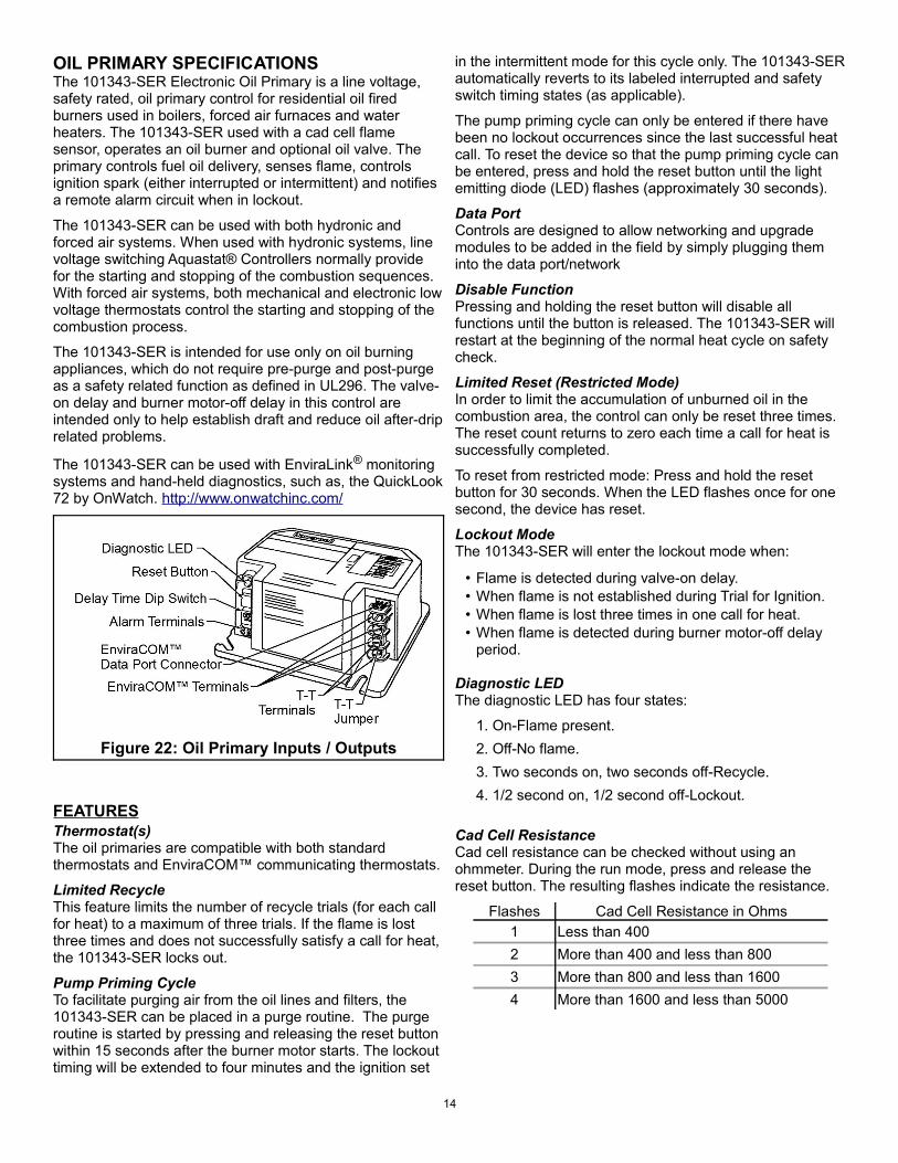
OIL PRIMARY SPECIFICATIONSThe 101343-SER Electronic Oil Primary is a line voltage, safety rated, oil primary control for residential oil fired burners used in boilers, forced air furnaces and water heaters. The 101343-SER used with a cad cell flame sensor, operates an oil burner and optional oil valve. The primary controls fuel oil delivery, senses flame, controls ignition spark (either interrupted or intermittent) and notifies a remote alarm circuit when in lockout.
The 101343-SER can be used with both hydronic and forced air systems. When used with hydronic systems, line voltage switching Aquastat® Controllers normally provide for the starting and stopping of the combustion sequences. With forced air systems, both mechanical and electronic low voltage thermostats control the starting and stopping of the combustion process.
The 101343-SER is intended for use only on oil burning appliances, which do not require pre-purge and post-purge as a safety related function as defined in UL296. The valve-on delay and burner motor-off delay in this control are intended only to help establish draft and reduce oil after-drip related problems.
The 101343-SER can be used with EnviraLink® monitoring systems and hand-held diagnostics, such as, the QuickLook 72 by OnWatch. http://www.onwatchinc.com/
Figure 22: Oil Primary Inputs / Outputs
FEATURESThermostat(s)The oil primaries are compatible with both standard thermostats and EnviraCOM™ communicating thermostats.
Limited RecycleThis feature limits the number of recycle trials (for each call for heat) to a maximum of three trials. If the flame is lost three times and does not successfully satisfy a call for heat, the 101343-SER locks out.
Pump Priming CycleTo facilitate purging air from the oil lines and filters, the 101343-SER can be placed in a purge routine. The purge routine is started by pressing and releasing the reset button within 15 seconds after the burner motor starts. The lockout timing will be extended to four minutes and the ignition set
in the intermittent mode for this cycle only. The 101343-SER automatically reverts to its labeled interrupted and safety switch timing states (as applicable).
The pump priming cycle can only be entered if there have been no lockout occurrences since the last successful heat call. To reset the device so that the pump priming cycle can be entered, press and hold the reset button until the light emitting diode (LED) flashes (approximately 30 seconds).
Data PortControls are designed to allow networking and upgrade modules to be added in the field by simply plugging them into the data port/network
Disable FunctionPressing and holding the reset button will disable all functions until the button is released. The 101343-SER will restart at the beginning of the normal heat cycle on safety check.
Limited Reset (Restricted Mode)In order to limit the accumulation of unburned oil in the combustion area, the control can only be reset three times. The reset count returns to zero each time a call for heat is successfully completed.
To reset from restricted mode: Press and hold the reset button for 30 seconds. When the LED flashes once for one second, the device has reset.
Lockout ModeThe 101343-SER will enter the lockout mode when:
• Flame is detected during valve-on delay.• When flame is not established during Trial for Ignition.• When flame is lost three times in one call for heat.• When flame is detected during burner motor-off delay
period.
Diagnostic LEDThe diagnostic LED has four states:
1. On-Flame present.2. Off-No flame.3. Two seconds on, two seconds off-Recycle.4. 1/2 second on, 1/2 second off-Lockout.
Cad Cell ResistanceCad cell resistance can be checked without using an ohmmeter. During the run mode, press and release the reset button. The resulting flashes indicate the resistance.
Flashes Cad Cell Resistance in Ohms1 Less than 4002 More than 400 and less than 8003 More than 800 and less than 16004 More than 1600 and less than 5000
14
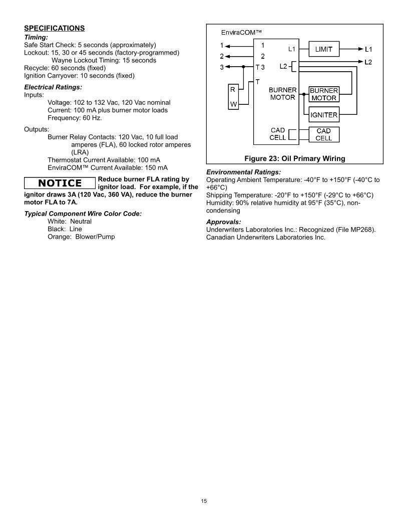
SPECIFICATIONSTiming:Safe Start Check: 5 seconds (approximately)Lockout: 15, 30 or 45 seconds (factory-programmed) Wayne Lockout Timing: 15 secondsRecycle: 60 seconds (fixed)Ignition Carryover: 10 seconds (fixed)
Electrical Ratings:Inputs:
Voltage: 102 to 132 Vac, 120 Vac nominalCurrent: 100 mA plus burner motor loadsFrequency: 60 Hz.
Outputs:Burner Relay Contacts: 120 Vac, 10 full load
amperes (FLA), 60 locked rotor amperes (LRA)
Thermostat Current Available: 100 mAEnviraCOM™ Current Available: 150 mA
Reduce burner FLA rating by ignitor load. For example, if the
ignitor draws 3A (120 Vac, 360 VA), reduce the burner motor FLA to 7A.Typical Component Wire Color Code:
White: NeutralBlack: LineOrange: Blower/Pump
Figure 23: Oil Primary Wiring
Environmental Ratings:Operating Ambient Temperature: -40°F to +150°F (-40°C to +66°C)Shipping Temperature: -20°F to +150°F (-29°C to +66°C)Humidity: 90% relative humidity at 95°F (35°C), non-condensing
Approvals:Underwriters Laboratories Inc.: Recognized (File MP268).Canadian Underwriters Laboratories Inc.
15
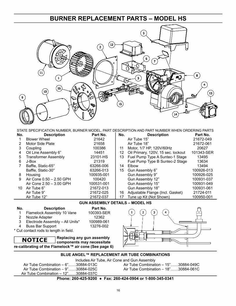
BURNER REPLACEMENT PARTS – MODEL HS
STATE SPECIFICATION NUMBER, BURNER MODEL, PART DESCRIPTION AND PART NUMBER WHEN ORDERING PARTSNo. Description Part No. No. Description Part No.1 Blower Wheel 21642 Air Tube 15” 21672-0492 Motor Side Plate 21658 Air Tube 18” 21672-0613 Coupling 100386 11 Motor, 1/7 HP, 120V/60Hz 206274 Oil Line Assembly 6” 14451 12 Oil Primary, 120V, 15 sec. lockout 101343-SER5 Transformer Assembly 23101-HS 13 Fuel Pump Type A Suntec-1 Stage 134956 J-Box 21319 Fuel Pump Type B Suntec-2 Stage 136347 Baffle, Static-65° 63266-006 14 Elbow 13494
Baffle, Static-30° 63266-013 15 Gun Assembly 6” 100926-0138 Housing 100935-001 Gun Assembly 9” 100926-0259 Air Cone 0.50 – 2.50 GPH 100420 Gun Assembly 12” 100931-037
Air Cone 2.50 – 3.00 GPH 100531-001 Gun Assembly 15” 100931-04910 Air Tube 6” 21672-013 Gun Assembly 18” 100931-061
Air Tube 9” 21672-025 16 Adjustable Flange (Incl. Gasket) 21724-011Air Tube 12” 21672-037 17 Tune up Kit (Not Shown) 100950-001
GUN ASSEMBLY DETAILS – MODEL HSNo. Description Part No.1 Flamelock Assembly 10 Vane 100393-SER2 Nozzle Adapter 123623 Electrode Assembly – All Units* 100989-0614 Buss Bar Support 13276-002
* Cut contact rods to length in field.
Replacing any gun assembly components may necessitate
re-calibrating of the Flamelock™ air cone (See page 6)
BLUE ANGEL™ REPLACEMENT AIR TUBE COMBINATIONSIncludes Air Tube, Air Cone and Gun Assembly
Air Tube Combination – 6”……30884-013C Air Tube Combination – 15”……30884-049CAir Tube Combination – 9”……30884-025C Air Tube Combination – 18”……30884-061C
Air Tube Combination – 12”……30884-037CPhone: 260-425-9200 ● Fax: 260-424-0904 or 1-800-345-0341
16
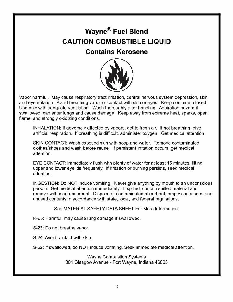
Wayne® Fuel BlendCAUTION COMBUSTIBLE LIQUID
Contains Kerosene
Vapor harmful. May cause respiratory tract irritation, central nervous system depression, skin and eye irritation. Avoid breathing vapor or contact with skin or eyes. Keep container closed. Use only with adequate ventilation. Wash thoroughly after handling. Aspiration hazard if swallowed, can enter lungs and cause damage. Keep away from extreme heat, sparks, open flame, and strongly oxidizing conditions.
INHALATION: If adversely affected by vapors, get to fresh air. If not breathing, give artificial respiration. If breathing is difficult, administer oxygen. Get medical attention.
SKIN CONTACT: Wash exposed skin with soap and water. Remove contaminated clothes/shoes and wash before reuse. If persistent irritation occurs, get medical attention.
EYE CONTACT: Immediately flush with plenty of water for at least 15 minutes, lifting upper and lower eyelids frequently. If irritation or burning persists, seek medical attention.
INGESTION: Do NOT induce vomiting. Never give anything by mouth to an unconscious person. Get medical attention immediately. If spilled, contain spilled material and remove with inert absorbent. Dispose of contaminated absorbent, empty containers, and unused contents in accordance with state, local, and federal regulations.
See MATERIAL SAFETY DATA SHEET For More Information.
R-65: Harmful: may cause lung damage if swallowed.
S-23: Do not breathe vapor.
S-24: Avoid contact with skin.
S-62: If swallowed, do NOT induce vomiting. Seek immediate medical attention.
Wayne Combustion Systems801 Glasgow Avenue • Fort Wayne, Indiana 46803
17
WAYNE COMBUSTION SYSTEMS801 Glasgow Ave.
Fort Wayne, IN 48803
LIMITED WARRANTIES FOR OIL ANDGAS BURNERS, MADE BY WAYNE ANDUSED IN RESIDENTIAL INSTALLATIONS
WAYNE COMBUSTION SYSTEMS (“WAYNE”) warrants to those who purchase its Oil Burner Models for resale or for incorporation into a product of resale, that its burner is free from defects in material and workmanship under normal use and service for thirty-six (36) months from the date of manufacture. ALL GAS BURNERS manufactured by “WAYNE” will be similarly warranted for eighteen(18) months from date of manufacture except where original manufacture offers a greater warranty. (Reference #6 below) THESE LIMITED WARRANTIES DO NOT APPLY UNLESS THE BURNER COVERED BY IT IS PROPERLY INSTALLED BY A QUALIFIED, COMPETENT TECHNICIAN, WHO IS LICENSED WHERE STATE AND/OR LOCAL CODES PREVAIL, AND WHO IS EXPERIENCED IN MAKING SUCH INSTALLATIONS, in accordance with NFPA #31 of the national fire protection association and in accordance with all local, state and national codes.
Any IN-WARRANTY burner component which is defective in material or workmanship will be either repaired or replaced as follows:
1. Fuel pumps, motors, transformers, gas valves, and controls should be returned to an authorized service station or distributor of WAYNE for determination of applicability of this LIMITED WARRANTY as to either repair or replacement, where said service station or distributor is reasonably available in the customer’s locality. The manufacturers of burner components regularly publish and distribute listings showing the locations of their network of service stations. Where such local service is NOT available for the burner components described above or other burner parts are involved, these items should be returned, freight prepaid, to WAYNE Service Department, 801 Glasgow Ave, Fort Wayne, Indiana 46803.
2. Burners and/or component(s) determined to be covered under this LIMITED WARRANTY by WAYNE shall be repaired or replaced at WAYNE’s sole option.
3. WAYNE is not responsible for any labor cost for the removal and replacement of said burner or burner components and equipment associated therewith.
4. A burner so repaired will then carry the LIMITED WARRANTY equal to the unexpired portion of the original burner LIMITED WARRANTY.
5. If inspection by WAYNE does NOT disclose any defect covered by this LIMITED WARRANTY, the burner or burner component(s) will be either repaired or replaced at the expense of the customer and WAYNE’s regular charges will apply.
6. If the original manufacturer of a burner component offers a warranty greater than either of our LIMITED WARRANTIES described above, then this portion will be added to our LIMITED WARRANTY. This LIMITED WARRANTY does NOT cover products that have been damaged as the result of accident, abuse, misuse, neglect, improper installations, improper maintenance or failure to operate in accordance with WAYNE’s written instructions.
These LIMITED WARRANTIES do not extend to anyone except the first purchaser at retail and only when the burner is in the original installation site.
IMPLIED WARRANTIES OF MERCHANTABILITY AND FITNESS FOR A PARTICULAR PURPOSE SHALL BE LIMITED TO THE DURATION OF THE LIMITED EXPRESS WARRANTIES CONTAINED HEREIN. WAYNE EXPRESSLY DISCLAIMS AND EXCLUDES ANY LIABILITY FOR CONSEQUENTIAL OR INCIDENTAL DAMAGES OF ANY NATURE FOR BREACH OF ANY EXPRESS OR IMPLIED WARRANTY.
Some states do not allow limitation on how long an implied warranty lasts, so the above limitation may not apply to you. Also, some states do not allow the exclusion or limitation of incidental or consequential damages, so the above limitation or exclusion may not apply to you. WAYNE neither assumes nor authorizes any person to assume for WAYNE any other liability or obligation in connection with the sale of these products. This warranty gives you specific legal rights, and you may also have other rights, which vary from state to state.
18

NOTES
19


![[Se T 05 0044] T I Prs Secure Log Appliance [2](https://img.pdfslide.us/doc/110x75/5598ec541a28ab7f118b4636/se-t-05-0044-t-i-prs-secure-log-appliance-2.jpg)
