Embed Size (px)
Citation preview

27.1.11 1Page
Bundle Pipeline Systems
& Shell FRAM Development
Iain Watson & Peter Walker
March 21st, 2012

Bundle Technologies
Advantages of Bundle Systems
Shell Fram Bundle FEED
Agenda
27.1.11 2Page 2Page 27.1.11
Shell Fram Bundle FEED

Bundle Technologies
Advantages of Bundle Systems
Agenda
27.1.11 3Page 3Page 27.1.11
Advantages of Bundle Systems
Shell Fram FEED

What is a Bundle / Towed Pipeline Solution?
• A Pipeline Bundle is a carrier pipe within which any combination ofindividual pipelines and umbilical components is carried.
• The individual components terminate in “Towheads” within whichmanifolding may take place.
• A Towed Pipeline Solution provides a low stress installation methodwhere-by a pipeline bundle is towed and installed using the ControlledDepth Tow Method.
27.1.11 4Page

Subsea 7 Installed Bundles
Åsgard
Heidrun
NorwayNorway
Osprey
Cormorant
Frigg East
Murchison
GullfaksBruce
Keith
• 65 bundles in 33 years
• Up to 7.6km length
• Up to 28.7km in series
• Up to 320m water depth
• Shallowest 42m
27.1.11 5Page
Claymore
PiperSaltire Thelma
Cyrus, FarragonScapa
Alba
Gannet
Embla
DanDenmarkDenmark
WickWick
ScotlandScotland
Buckland
Keith
LeadonSkene
• Longest tow 1000 km
• Up to 49.5” carrier
• Up to 545 te towhead
• Heaviest bundle 9154 te
• Up to 3 PiP flowlines
• U-value <0.7 W/m2K
• 3 Ongoing Projects
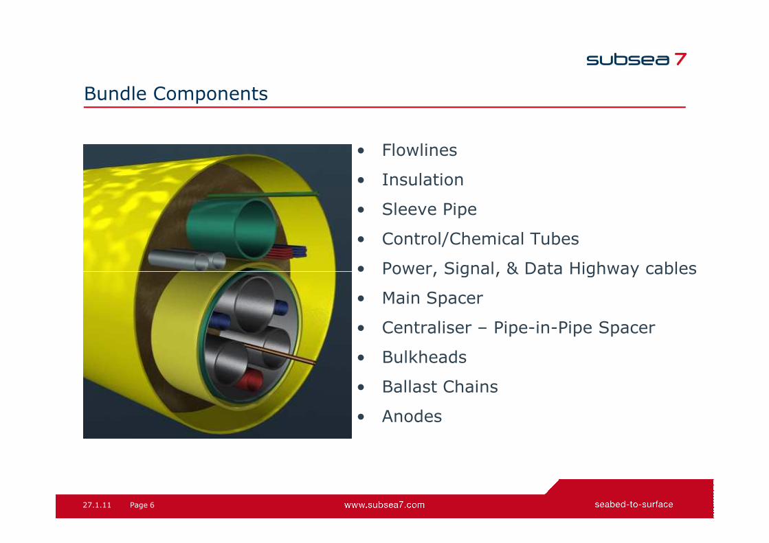
Bundle Components
• Flowlines
• Insulation
• Sleeve Pipe
• Control/Chemical Tubes
• Power, Signal, & Data Highway cables
27.1.11 6Page
• Power, Signal, & Data Highway cables
• Main Spacer
• Centraliser – Pipe-in-Pipe Spacer
• Bulkheads
• Ballast Chains
• Anodes

What exactly is a “Pipeline Bundle?”
27.1.11 7Page

Typical Bundle Layout
BP Machar
27.1.11 8Page
BP Andrew
Kerr McGee Leadon

Materials
Flowline Materials
• Carbon steel - X52, X65, X70 with SS or
Alloy Liners
• Corrosion Resistant Alloys - 13% 22% & 25%
Cr Steels
27.1.11 9Page
• Plastic (HDPE) Liners for Water Injection Lines
Controls
• Hard Pipe Hydraulic and Chemical Systems -
316 SS, 25% Cr Duplex to Carbon Steel
• Electrical & Fibre Optic Control Systems

The Long Trek West
27.1.11 10Page
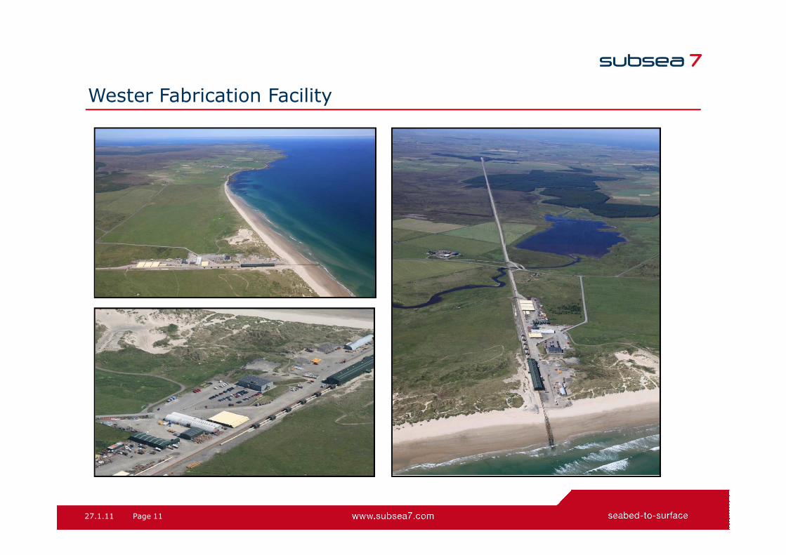
Wester Fabrication Facility
27.1.11 11Page
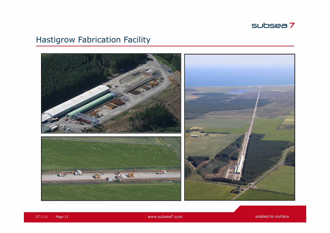
Hastigrow Fabrication Facility
27.1.11 12Page

Welding Firing Lines
27.1.11 13Page

Inner Bundle Fabrication
27.1.11 14Page

Insulation Type
Pipe-in-Pipe System
Passive Insulation System
27.1.11 15Page
Pipe-in-Pipe System
Electrical Active/Trace Heating
Indirect Hot Water Heating
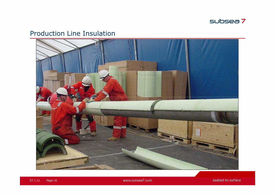
Production Line Insulation
27.1.11 16Page

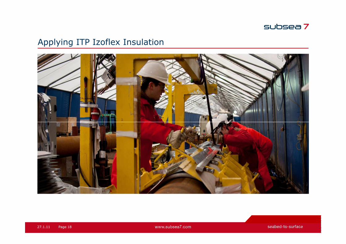
Applying ITP Izoflex Insulation
27.1.11 17Page
Applying ITP Izoflex Insulation
27.1.11 18Page

Spot Welding Steel Sheet Over ITP Izoflex
27.1.11 19Page

Spot Welding Steel Sheet Over ITP Izoflex
27.1.11 20Page
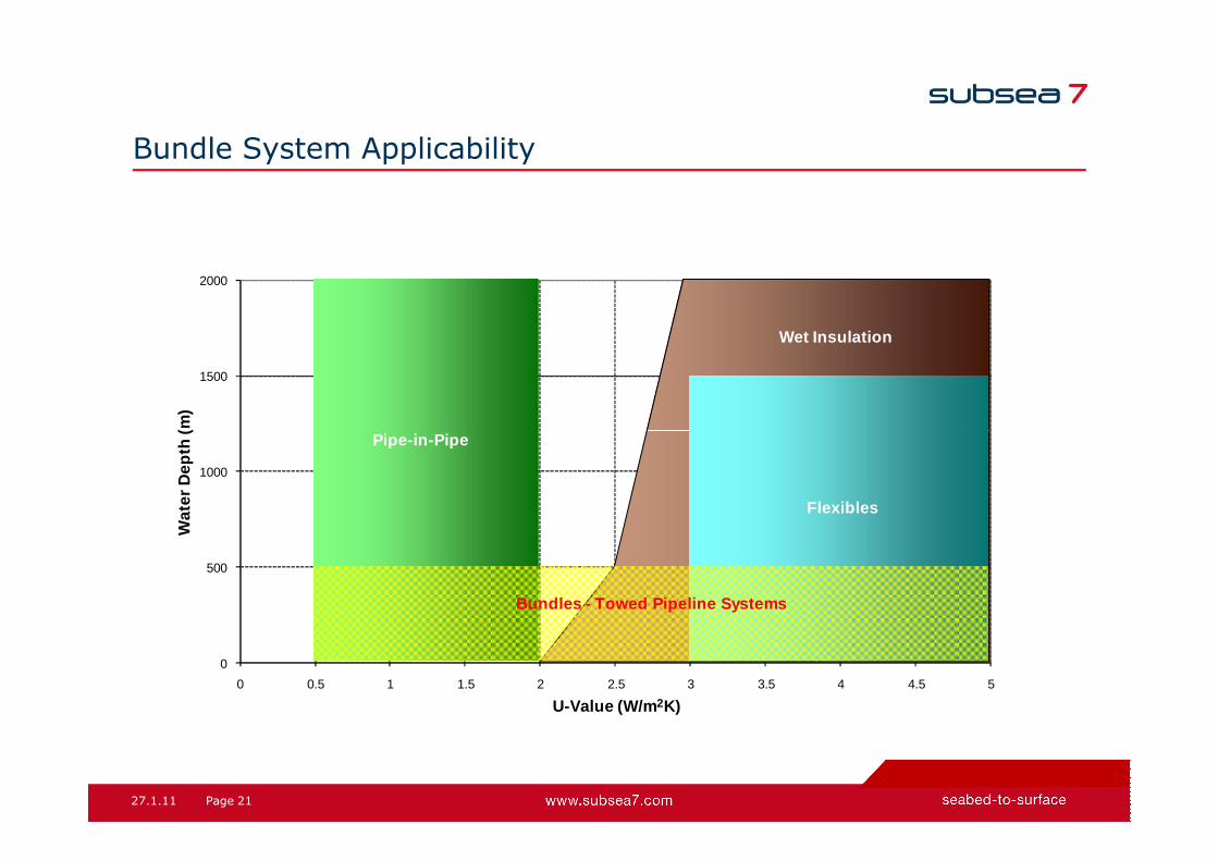
Bundle System Applicability
1500
2000
Wat
er D
epth
(m)
Pipe-in -Pipe
Wet Insulation
27.1.11 21Page
0
500
1000
0 0.5 1 1.5 2 2.5 3 3.5 4 4.5 5
Wat
er D
epth
(m)
U-Value (W/m 2K)
Pipe-in -Pipe
Bundles - Towed Pipeline Systems
Flexibles

Flow Assurance – Geometry of Pipelines
• The environment within the carrier pipe provides an ideal opportunity forinnovative solutions in Flow Assurance.
• The pipelines can be arranged to facilitate heat transfer between product linesor from dedicated heating lines.
• Heat transfer analysis confirmed by experimental results.
27.1.11 22Page
Active Heating Systems
� Warm-up before Start-up
� Increase Temperatures for Low Production Rates
� Keep System Temperature High during Shutdowns
� Reduce Chemical Injection
Six Active Heating Systems installed in the North Sea
Hot Water Circulation over distances of 15 km
Electric Heat Transfer
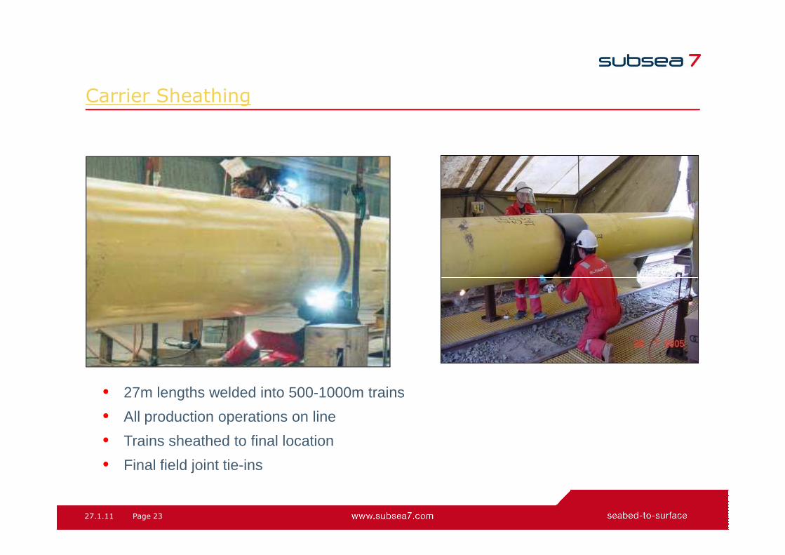
Carrier Sheathing
27.1.11 23Page
• 27m lengths welded into 500-1000m trains
• All production operations on line
• Trains sheathed to final location
• Final field joint tie-ins

Towheads
27.1.11 24Page

Jura Manifold Beach Landing
27.1.11 25Page

Jura Manifold Beach Landing
27.1.11 26Page
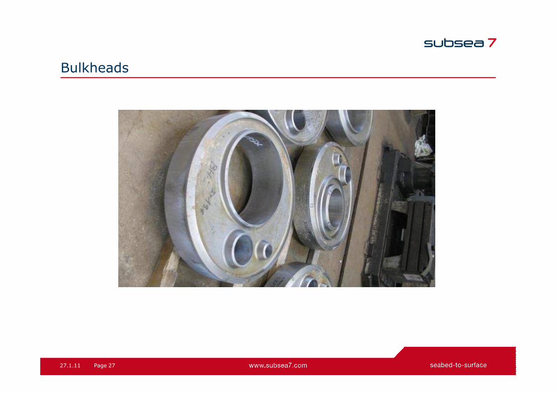
Bulkheads
27.1.11 27Page

Bulkheads
27.1.11 28Page

Towhead Tie-In
27.1.11 29Page

Bundle Launch
• Structures greater than 500Te
• Tidal currents monitored & tug
locations altered accordingly
• Tug bollard pull up to 400Te
• Capstan winch providing
holdback tension up to 70Te
27.1.11 30Page
holdback tension up to 70Te
• A99 road bridge opens to allow
large structures to pass through
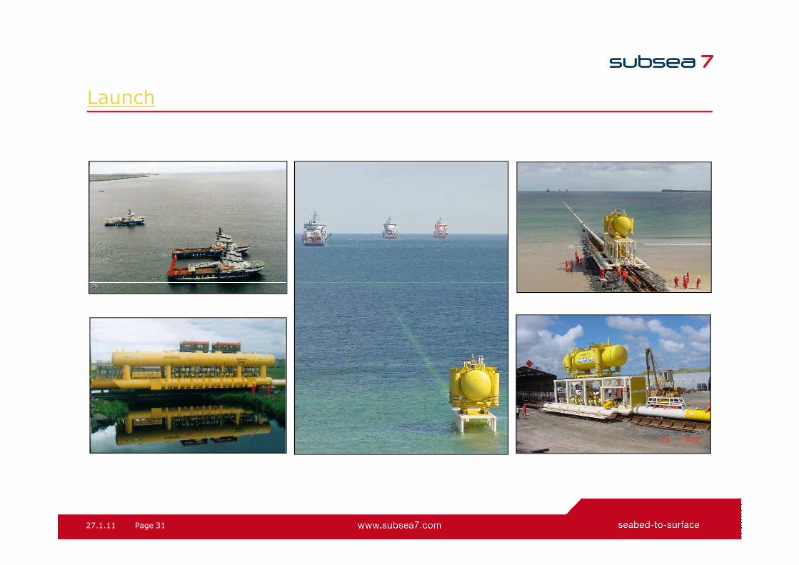
Launch
27.1.11 31Page

Control Depth Tow Method
• Chains attached at regular intervals along the bundle.
• Ensures accurate weight control to approximately 0.5%.
• Weight of chain links on seabed is submerged weight of bundle.
• Chains can be easily cut by ROV to trim bundle
27.1.11 32Page
• Chains can be easily cut by ROV to trim bundle for tow if required.

CDTM – in Practice
27.1.11 33Page
A data highway runs thelength of the bundle andallows acoustic commandsmade at one end of thebundle to be implemented atthe other, for example forvalve actuation or acousticspool metrology.
Towmaster’s real-time display of bundle shape and water depth

What We Can Do
• Field Concept Development, FEED Studies
• Tender Engineering
• Detailed Design & Fabrication
• Launch, Tow & Installation Analysis
• Dynamic & Fatigue Analysis
• Failure Investigation Support
27.1.11 34Page
• Failure Investigation Support
• Regional Support (Bundles), Norway & Asia Pacific

Bundle Technologies
Advantages of Bundle Systems
Shell Fram Bundle FEED
Agenda
27.1.11 35Page 35Page 27.1.11
Shell Fram Bundle FEED

Why Bundles? - Advantages
• Eliminate the requirement for heavy lift vessels by incorporating Subsea Structures within a
Towed Production System (Maximum to date 545te).
• Testing and commissioning of complete system onshore therefore reducing offshore time: -
Hydro testing, dewatering, drying, control fluid flushing, valve operations etc.
• Fast hook up and commissioning for early first oil dates.
• Installation under existing or temporary floating assets.
27.1.11 36Page
• Reduced number of subsea tie-ins and spool installations.
• Seabed stability using Gravity Based or Piled design.
• Protection incorporated in structure design.
• Improved Flow Assurance / thermal Management (Heated – Hot Water, Trace Heating).
• Leak mitigation in case of internal flowline failure (maintain leaked oil within Carrier Annulus) -
Flowline safety class can be reduced when using DNV-OS-F101 Design Code.
• Use of CRA Lined pipe in place of Clad pipe or solid CRA pipe.
• High Temperature Flowline Design (up to 160°C curre ntly).
• Turn out cost more predictable (reduced exposure to weather/soils risk).

Bundle Technologies
Advantages of Bundle Systems
Shell Fram Bundle FEED
Agenda
27.1.11 37Page 37Page 27.1.11
Shell Fram Bundle FEED

Fram Field Location
27.1.11 38Page

Fram Field Location
27.1.11 39Page

Fram Development Proposed Field Concept
27.1.11 40Page

Fram Development – Proposed Field Layout (Xodus)
27.1.11 41Page

Fram Infield Layout
27.1.11 42Page

Fram FPSO Approaches (Xodus)
27.1.11 43Page

Fram Drill Centre East Towhead & Well Tie-ins (Xodus)
27.1.11 44Page

Fram Drill Centre West Towhead & Well Tie-ins (Xodus)
27.1.11 45Page

Fram Bundle FEED - Principal Design Assumptions
Principal Design Data / Assumptions for Fram FEED:
• 8 Slot towhead manifold at DCE (5 wells initially).
• 6 Slot towhead manifold at DCW (3 wells initially).
• 2 midline SSIV structures required at FPSO (out with swing circle).
• 14” NB Gas Export SSIV located in Midline Towhead (East).
• Shared services between drill centres (single test riser, gas lift riser & riser umbilical).
27.1.11 46Page
• Shared services between drill centres (single test riser, gas lift riser & riser umbilical).
• Mixture of Oil & Gas Wells at both drill centres.
• 345 Barg Design Pressure / 110°C Design Temperature (Production/Test).
• Max CO2 content ~1.1 mol.% in produced fluids.
• Max. H2S ~6 ppmv in produced fluids.
• ~47,000 mg/l Chlorides in produced water.
• Water depth infield ~ 95 m (wrt LAT).
• 20 year system design life
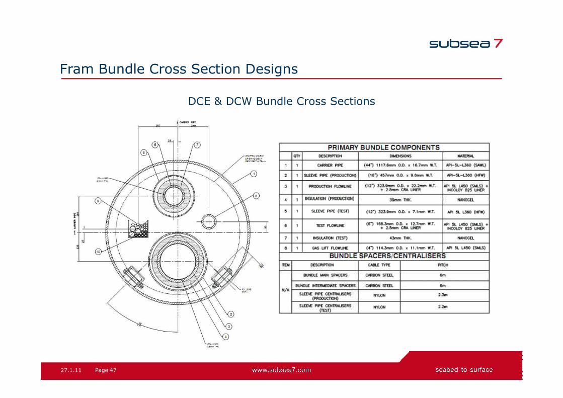
Fram Bundle Cross Section Designs
DCE & DCW Bundle Cross Sections
27.1.11 47Page
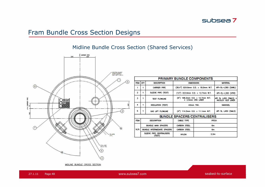
Midline Bundle Cross Section (Shared Services)
Fram Bundle Cross Section Designs
27.1.11 48Page
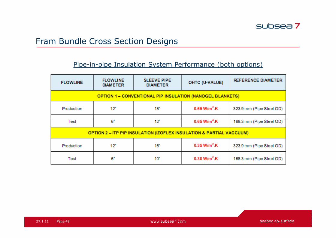
Fram Bundle Cross Section Designs
Pipe-in-pipe Insulation System Performance (both options)
27.1.11 49Page

CRA Lined Pipe (Butting) – Mechanically Bonded (BuBi)
Fram Bundle Production & Test Line Linepipe Design
27.1.11 50Page
The Mechanically bonded Butting Bimetal Pipe (BuBi Linepipe)
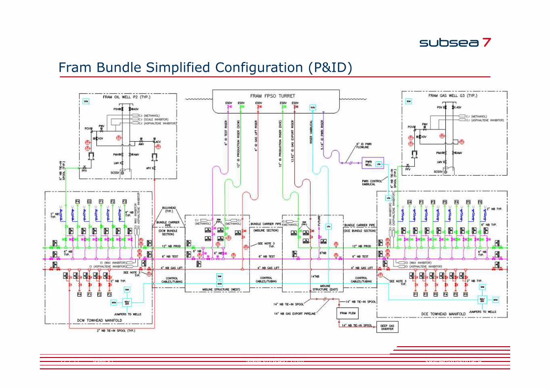
Fram Bundle Simplified Configuration (P&ID)
27.1.11 51Page
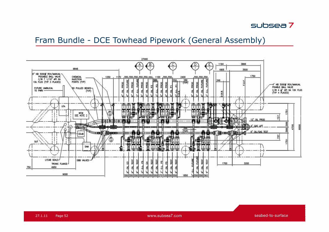
Fram Bundle - DCE Towhead Pipework (General Assembly)
27.1.11 52Page

Fram Bundle - DCW Towhead (General Assembly)
27.1.11 53Page

Fram Bundle - Midline Structure East (GA)
27.1.11 54Page

Fram Bundle - Midline Structure West (GA)
27.1.11 55Page
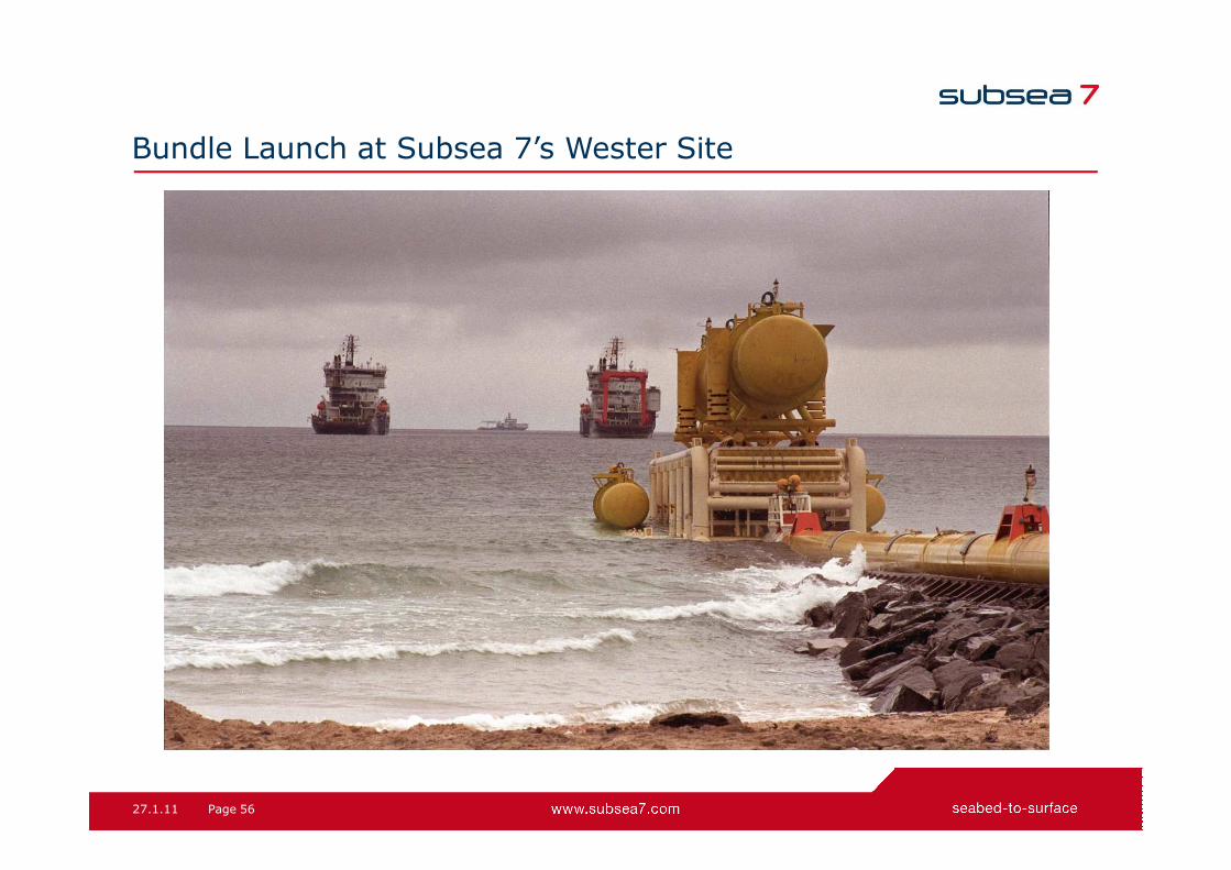
Bundle Launch at Subsea 7’s Wester Site
27.1.11 56Page

Bundle Tow Route
27.1.11 57Page

Bundle Tow Configuration
27.1.11 58Page

Bundle Tow Route
27.1.11 59Page

Control Depth Tow Method
• Chains attached at regular intervals along the bundle.
• Ensures accurate weight control to approximately 0.5%.
• Weight of chain links on seabed is submerged weight of bundle.
• Chains can be easily cut by ROV to trim bundle
27.1.11 60Page
• Chains can be easily cut by ROV to trim bundle for tow if required.

Questions?
27.1.11 61Page

27.1.11 62Page
seabed-to-surface
www.subsea7.com

![FERROELECTRIC RAM [FRAM] - Study Mafiastudymafia.org/wp...FERROELECTRIC-RAM-FRAM-Report.pdf · A Seminar report On FERROELECTRIC RAM [FRAM] Submitted in partial fulfillment of the](https://img.pdfslide.us/doc/110x75/5b94f2f009d3f2130d8dd6e1/ferroelectric-ram-fram-study-a-seminar-report-on-ferroelectric-ram-fram.jpg)


![FERROELECTRIC RAM [FRAM]](https://img.pdfslide.us/doc/110x75/56816799550346895ddcd567/ferroelectric-ram-fram.jpg)