Embed Size (px)
Citation preview
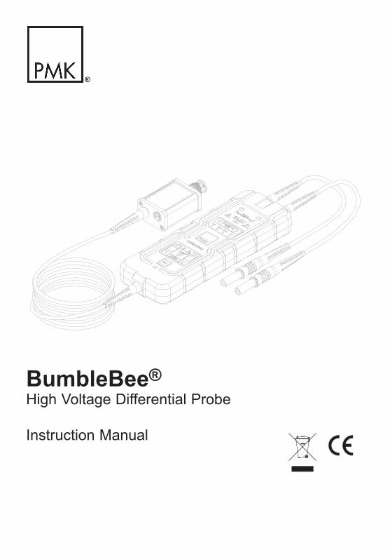
BumbleBee®High Voltage Differential Probe
Instruction Manual
2
Copyright © 2016 PMK GmbH All rights reserved.
Information in this publication supersedes that in all previously published material.Specifications are subject to change without notice.
Manufacturer
PMK Mess- und Kommunikationstechnik GmbHKönigsteiner Str. 9865812 Bad Soden, Germany Internet: www.pmk.de
Tel: +49 (0) 6196 5927 - 930 E-Mail: [email protected]: +49 (0) 6196 5927 - 939
Warranty
PMK GmbH warrants this oscilloscope accessory for normal use and operation within specifications for a peri-od of two (2) years from date of shipment and will repair or replace any defective product which was not dama-ged by negligence, misuse, improper installation, accident or unauthorized repair or modification by the buyer. This warranty is applicable only to defects due to material or workmanship. PMK GmbH disclaim any other implied warranties of merchantability or fitness for a particular purpose. PMK GmbH will not be liable for any indirect, special, incidental, or consequential damages (including damages for loss of profits, loss of business, loss of use or data, interruption of business and the like), even if PMK GmbH has been advised of the possibility of such damages arising from any defect or error in this manual or product.
3
Declaration of Conformity BumbleBee®
(EC conformity marking)
The manufacturer declares,that this product is designed and manufactured in accordance with the requirements of the specified Directives and Standards as listed below. The product carries the CE mark.
EU Directives covered by this declaration:
2004/108/EC Electromagnetic Compatibility Directive2006/95/EC Low Voltage Equipment Directive 2002/96/EC Waste Electrical and Electronic Equipment 2002/95/EC Restriction of use of certain Hazardous Substances and its revised version 2011/65/EU
The basis on which conformity is being declared:
EN61010-1:2010 Safety requirements for electrical equipment for measurement, control and laboratory use, general equipment requirements
EN61010-031:2002 + A1:2008Safety requirements for hand-held probe assemblies for electrical measurement and test
EN61326-1:2006 Electrical equipment for measurement, control and laboratory use –EMC requirements. Basic Immunity - static discharge per EN61000-4-2
RoHS and WEEE Statements and Confirmations issued by our vendors that no hazardous or restricted sub-stances are used to manufacture components, parts and subassemblies for our products.
WEEE/ RoHS Directives
(EC conformity marking)
Your help and efforts are required to protect and keep clean our environment. Therefore return this electronic product at the end of its life either to the Service Department of PMK Mess- und Kommunikationstechnik GmbH or take care of separate WEEE collection and professional WEEE treatment yourself. Do not dispose as unsorted municipal waste.
* EC Directives:WEEE Directive 2002/96/EC - Waste Electrical and Electronic EquipmentRoHS Directive 2002/95/EC - Restriction of the use of certain Hazardous Substances in Electrical and Electronic Equipment
4
IEC Measurement Categories BumbleBee®
Definitions and Examples (Clause 6.5.2)
Measurement Category I Definition: Measurement category I is for measurements performed on circuits not directly connected to a mains supply.
Examples: Measurements in circuits not derived from a mains supply and specially protected ( internal ) circuits derived from a mains supply. In the latter case, transient stresses are variable; for that reason it is required that the transient withstand capability of the equipment is made known to the user.
Measurement Category II Definition: Measurement category II is for measurements performedCAT II on circuits directly connected to the low voltage installation.
Examples: Household appliances, portable tools and similar equipment.
Measurement Category III Definition: Measurement category III is for measurements CAT III performed in the building installation.
Examples: Measurements on distribution boards, circuit breakers, wiring including cables, bus-bars, junction boxes, switches, socket-outlets in the fixed installation and equipment for industrial use like for example stationary motors with per- manent connection to the fixed installation.
Measurement Category IV Definition: Measurement category IV is for measurements CAT IV performed at the source of the low-voltage installation.
Examples: Electricity meters and measurements on primary over current protection devices and and ripple control units.
5
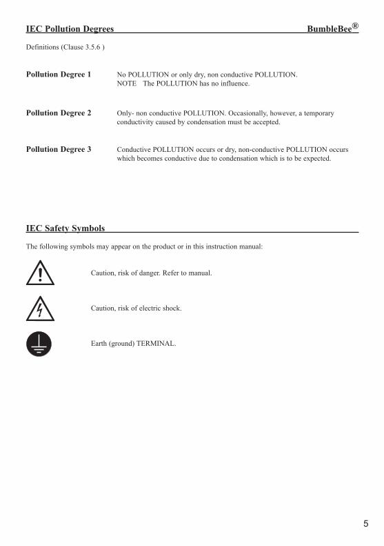
IEC Pollution Degrees BumbleBee®
Definitions (Clause 3.5.6 )
Pollution Degree 1 No POLLUTION or only dry, non conductive POLLUTION. NOTE The POLLUTION has no influence.
Pollution Degree 2 Only- non conductive POLLUTION. Occasionally, however, a temporary conductivity caused by condensation must be accepted.
Pollution Degree 3 Conductive POLLUTION occurs or dry, non-conductive POLLUTION occurs which becomes conductive due to condensation which is to be expected.
IEC Safety Symbols
The following symbols may appear on the product or in this instruction manual:
Caution, risk of danger. Refer to manual.
Caution, risk of electric shock.
Earth (ground) TERMINAL.
6
Safety Information BumbleBee®
To avoid personal injury and to prevent fire or damage to this product or products connected to it, review and comply with the following safety precautions. Be aware that if you use this probe assembly in a manner not specified the protection this product provides may be impaired.Only qualified personnel should use this probe assembly.
Use only grounded instruments.Do not connect the probe ground lead to a potential other than earth ground. Always make sure the probe and the measurement instrument are grounded properly.
Connect and disconnect properly.Connect the probe output to the measurement instrument and connect the ground lead to earth ground before connecting the probe to the circuit under test. Disconnect the probe input and the probe ground lead from the circuit under test before disconnecting the probe from the measurement instrument.
Avoid unnecessary stress.The small electrical components of the probe are sensitive to shock and impact. Avoid any unnecessary kinetic stress to the probe like throwing, falling and strong vibrations.
Observe probe and probe accessory ratings.Do not apply any electrical potential to the probe input which exceeds the maximum ratings of the probe or the accessories connected to it. In a combination always the lower rating / measurement category applies to both probe and accessories connected to it. Make sure to comply with the voltage versus frequency derating curve on page 8.
Keep away from live circuits.Avoid open circuitry. Do not touch connections or components when power is present.
Do not operate with suspected failures.Refer to qualified service personnel.
Indoor use only.Do not operate in wet/damp environment. Keep product surfaces dry and clean.
Do not operate the product in an explosive atmosphere.
7
Safety Information BumbleBee®
BumbleBee has a rated Input Voltage of 2000 V Measurement Category I or 1000 V CAT III.
Note that the max. input voltage rating of the probe decreases as the frequency of the applied signal increases. (see Voltage Derating on page 9)
See the relevant section of this manual for further information on maximum input voltage, voltage derating and definitions of relevant IEC Measurement Categories (CAT).
Grounding the ProbeConnect the probe to the oscilloscope input and connect the ground lead to earth ground before performing any measurements.
BumbleBee is designed for ground-referenced measurements only.
About BumbleBee
BumbleBee® is a 400 MHz, 2 kV Measurement Category I or 1 kV CAT III High-Voltage Differential Probe, that can be used with every instrument having 50 Ω Input Impedance.The probe is very effective in power device evaluation such as measurements in IGBT circuits used in the design of motor drives, switching power supplies and frequency converters. Especially 1700 V IGBT modules for inverters and converters.BumbleBee is also very effective in fast transient measurements with bandwidths of up to 400 MHz. Measurments at GaN and SiC modules as part of new semiconductor techniques profit from that in particular.It provides a 4 Mode Attenuation, which allows higher resolution measurements. The probe provides overload indicators for each input channel as well as for the output. That makes it easy to observe, that the differential probe is working in the specified range.The probe also provides an active offset correction in a range of ± 4 V, related to the output voltage, with a resolution of 15 Bit.
These and many other functions can be remotely controlled with the PC-Software "PMK Probe Control".The Software is free and included in the scope of delivery of PMKs PS-02 and PS-03 Power Supplies. The intuitive grafical user interface makes all interactions with BumbleBee clear and easy.
Measurement PrincibleThe differential probe consists of two attenuators, which are differentially matched. The Voltage measurements of these attenuators is conducted ground-referenced. The read voltages are provided to a differential amplifier, where the differential voltage is amplified according to the choosen attenuation. The Output Signal is fed over a driver stage to the 50 Ω Input of a measuring device.
8
Specifications BumbleBee®
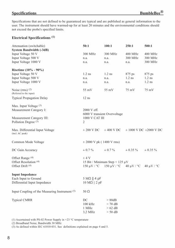
Specifications that are not defined to be guaranteed are typical and are published as general information to the user. The instrument should have warmed-up for at least 20 minutes and the environmental conditions should not exceed the probe's specified limits.
Electrical Specifications (1)
Attenuation (switchable) 50:1 100:1 250:1 500:1 System Bandwidth (-3dB)Input Voltage 50 V 300 MHz 300 MHz 400 MHz 400 MHz Input Voltage 500 V n.a. n.a. 300 MHz 300 MHzInput Voltage 1000 V n.a. n.a. n.a. 300 MHz
Risetime (10% - 90%)Input Voltage 50 V 1.2 ns 1.2 ns 875 ps 875 ps Input Voltage 500 V n.a. n.a. 1.2 ns 1.2 nsInput Voltage 1000 V n.a. n.a. n.a. 1.2 ns
Noise (rms) (2) 55 mV 55 mV 75 mV 75 mV(Referred to the input)
Typical Propagation Delay 12 ns
Max. Input Voltage (3)
Measurement Category I: 2000 V eff. 6000 V transient OvervoltageMeasurement Category III: 1000 V CAT IIIPollution Degree (3) 2
Max. Differential Input Voltage ± 200 V DC ± 400 V DC ± 1000 V DC ±2000 V DC(incl. AC peak)
Common Mode Voltage ± 2000 V pk ( 1400 V rms)
DC Gain Accuracy ± 0.7 % ± 0.7 % ± 0.35 % ± 0.35 %
Offset Range (4) ± 4 VOffset Resolution (4) 15 Bit / Minimum Step < 125 µVOffset Drift (4) 150 µV / °C 150 µV / °C 40 µV / °C 40 µV / °C
Input ImpedanceEach Input to Ground 5 MΩ || 4 pFDifferential Input Impedance 10 MΩ || 2 pF
Input Coupling of the Measuring Instrument (5) 50 Ω
Typical CMRR DC > 80dB 100 kHz > 70 dB 1 MHz > 62 dB 3,2 MHz > 50 dB
(1) Ascertained with PS-02 Power Supply in +23 °C temperature(2) Broadband Noise, Bandwidth 30 MHz(3) As defined within IEC 61010-031. See definitions explained on page 4 and 5.
9
Specifications BumbleBee®
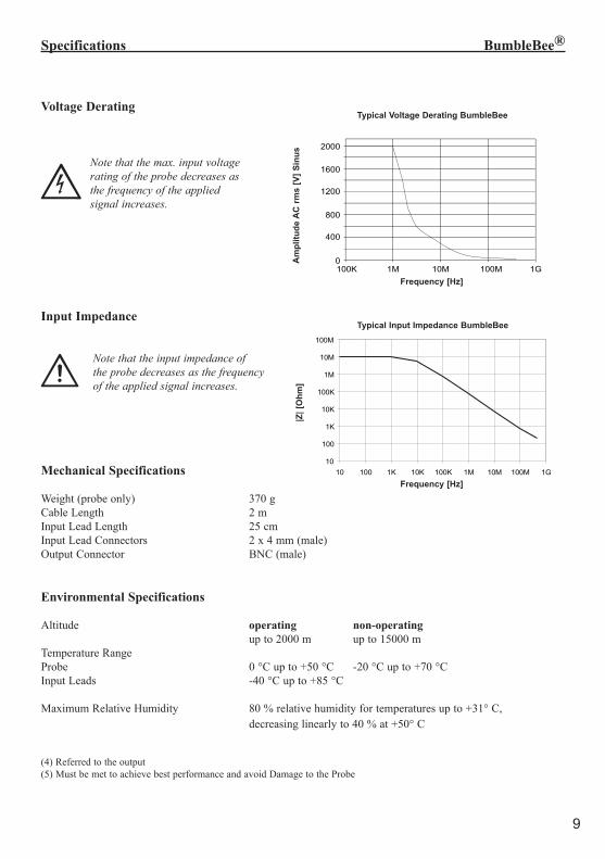
Voltage Derating
Note that the max. input voltage rating of the probe decreases as the frequency of the applied signal increases.
Input Impedance
Note that the input impedance of the probe decreases as the frequency of the applied signal increases.
Mechanical Specifications
Weight (probe only) 370 gCable Length 2 mInput Lead Length 25 cmInput Lead Connectors 2 x 4 mm (male)Output Connector BNC (male)
Environmental Specifications
Altitude operating non-operating up to 2000 m up to 15000 mTemperature RangeProbe 0 °C up to +50 °C -20 °C up to +70 °CInput Leads -40 °C up to +85 °C
Maximum Relative Humidity 80 % relative humidity for temperatures up to +31° C, decreasing linearly to 40 % at +50° C
(4) Referred to the output(5) Must be met to achieve best performance and avoid Damage to the Probe
Typical Voltage Derating BumbleBeeMeasurement category III
Frequency [Hz]
Ampl
itude
AC
rms
[V]s
inus
100K 1M 10M 100M 1G0
400
800
1200
1600
2000
Typical Voltage Derating BumbleBee
Frequency [Hz]
Frequency [Hz]
Typical Input Impedance BumbleBee
10
100
1K
10K
100K
1M
10M
100M
10 100 1K 10K 100K 1M 10M 100M 1G
Frequency [Hz]
|Z| [
Ohm
]
Typical Input Impedance BumbleBee
|Z| [
Ohm
]A
mpl
itude
AC
rms
[V] S
inus
10
Handling for Firmware v.3.5 and above BumbleBee®
General Information:
Adjust the Input Coupling of the Measuring Instrument to 50 Ω before connecting the probe to it.After connecting the power supply you hear a short triplet of signals from the buzzer and the LEDs of the key-board blink. You may start with your measurements or adjust attenuation and offset correction.
User Default:Settings of the BumbleBee Probe are saved in real-time, with no need to actively save or recall at any time.
Global Offset:By pressing "Set" you can switch between the set global offset position and zero. While in setup menu, this function is not available. Also with set "Hold Overload" an occuring Overload Event must be cleared before switching offset Zero position is available.
Factory Settings:By pressing both Buttons "1+2" together while in Setup Menu, the probe resets to factory settings. Hold both buttons down for 5 Seconds; wait until you hear a differing signal.
Setup Menu:By holding the "Set" Button down for five seconds you reach the Setup Menu of BumbleBee.(Overvoltage-indicator LED of the output blinks green)The focused Menu Item is indicated by the attenuation LEDs. This focus can be altered with the buttons "1" and "2". Use the Buttons "5" and "6" to alter settings of the focused Menu Item. Pressing the "Set" Button again ends the menu.
Keylock:If no key is pressed 10 seconds after opening the menu the keypad will be locked. Press the "Set" Button again to release it.
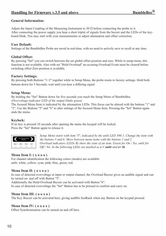
Setup Menu starts with item "I", indicated by the unlit LED 500:1. Change the item with the buttons 5 and 6. Move between menu items with the buttons 1 and 2. Overload indicators (LEDs B) show the state of an item. Green for On / Yes, unlit for Off / No. In the following LEDs are marked as x = unlit and o= lit. Menu Item I: ( x o o o )For channel identification the following colors (modes) are available: unlit, white, yellow, cyan, pink, blue, green, red;
Menu Item II: ( o x o o )In case of detected overvoltage at input or output channel, the Overload Buzzer gives an audible signal and can be turned on- and off with Button "5". Additionally the Hold-Overload Buzzer can be activated with Button "6".In case of detected overvoltage the "Set" Button has to be pressed to confirm and carry on.
Menu Item III: ( o o x o )The Key Buzzer can be activated here, giving audible feedback when any Button on the keypad pressed.
Menu Item IV: ( o o o x )Offset Synchronisation can be turned on and off here.
11
Keyboardlayout BumbleBee®
Menu Item V: ( o x x x )Here you can adjust the Offset-Zero for 500:1 attenuation.
Menüpunkt VI: ( x o x x )Here you can adjust the Offset-Zero for 250:1 attenuation.
Menüpunkt VII: ( x x o x )Here you can adjust the Offset-Zero for 100:1 attenuation.
Menüpunkt VIII: ( x x x o )Here you can adjust the Offset-Zero for 50:1 attenuation.
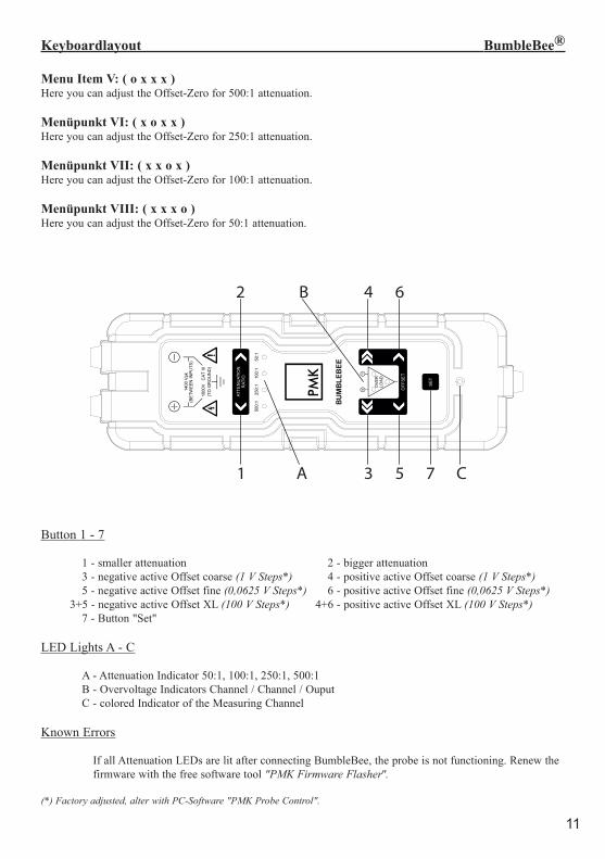
Button 1 - 7
1 - smaller attenuation 2 - bigger attenuation 3 - negative active Offset coarse (1 V Steps*) 4 - positive active Offset coarse (1 V Steps*) 5 - negative active Offset fine (0,0625 V Steps*) 6 - positive active Offset fine (0,0625 V Steps*) 3+5 - negative active Offset XL (100 V Steps*) 4+6 - positive active Offset XL (100 V Steps*) 7 - Button "Set"
LED Lights A - C
A - Attenuation Indicator 50:1, 100:1, 250:1, 500:1 B - Overvoltage Indicators Channel / Channel / Ouput C - colored Indicator of the Measuring Channel
Known Errors
If all Attenuation LEDs are lit after connecting BumbleBee, the probe is not functioning. Renew the firmware with the free software tool "PMK Firmware Flasher".
(*) Factory adjusted, alter with PC-Software "PMK Probe Control".
1 A
2 B
3
4
5
6
7 C
2
B
4
6
1
A
3
5
7
C
12
Performance Verification BumbleBee®
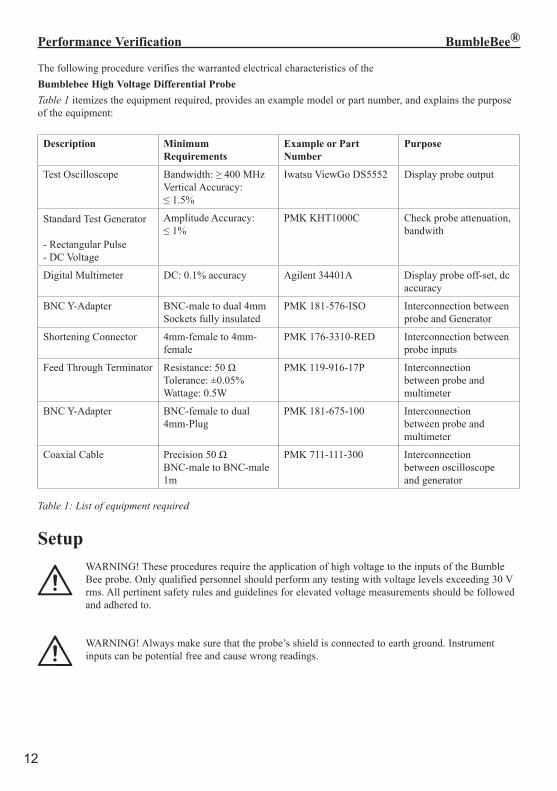
The following procedure verifies the warranted electrical characteristics of theBumblebee High Voltage Differential ProbeTable 1 itemizes the equipment required, provides an example model or part number, and explains the purpose of the equipment:
Description Minimum Requirements
Example or Part Number
Purpose
Test Oscilloscope Bandwidth: ≥ 400 MHzVertical Accuracy:≤ 1.5%
Iwatsu ViewGo DS5552 Display probe output
Standard Test Generator
- Rectangular Pulse- DC Voltage
Amplitude Accuracy:≤ 1%
PMK KHT1000C Check probe attenuation, bandwith
Digital Multimeter DC: 0.1% accuracy Agilent 34401A Display probe off-set, dc accuracy
BNC Y-Adapter BNC-male to dual 4mm Sockets fully insulated
PMK 181-576-ISO Interconnection between probe and Generator
Shortening Connector 4mm-female to 4mm-female
PMK 176-3310-RED Interconnection between probe inputs
Feed Through Terminator Resistance: 50 ΩTolerance: ±0.05%Wattage: 0.5W
PMK 119-916-17P Interconnection between probe and multimeter
BNC Y-Adapter BNC-female to dual 4mm-Plug
PMK 181-675-100 Interconnection between probe and multimeter
Coaxial Cable Precision 50 ΩBNC-male to BNC-male 1m
PMK 711-111-300 Interconnectionbetween oscilloscopeand generator
Table 1: List of equipment required
Setup WARNING! These procedures require the application of high voltage to the inputs of the Bumble Bee probe. Only qualified personnel should perform any testing with voltage levels exceeding 30 V rms. All pertinent safety rules and guidelines for elevated voltage measurements should be followed and adhered to.
WARNING! Always make sure that the probe’s shield is connected to earth ground. Instrument inputs can be potential free and cause wrong readings.
13
Performance Verification BumbleBee®
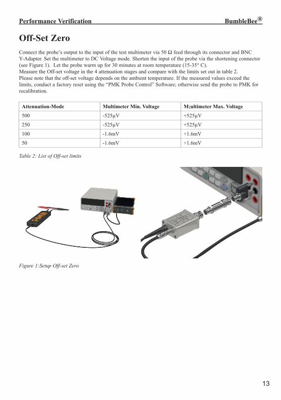
Off-Set ZeroConnect the probe’s output to the input of the test multimeter via 50 Ω feed through its connector and BNC Y-Adapter. Set the multimeter to DC Voltage mode. Shorten the input of the probe via the shortening connector (see Figure 1). Let the probe warm up for 30 minutes at room temperature (15-35° C).Measure the Off-set voltage in the 4 attenuation stages and compare with the limits set out in table 2. Please note that the off-set voltage depends on the ambient temperature. If the measured values exceed the limits, conduct a factory reset using the “PMK Probe Control” Software; otherwise send the probe to PMK for recalibration.
Attenuation-Mode Multimeter Min. Voltage M;ultimeter Max. Voltage
500 -525µV +525µV
250 -525µV +525µV
100 -1.6mV +1.6mV
50 -1.6mV +1.6mV
Table 2: List of Off-set limits
Figure 1:Setup Off-set Zero
14
Performance Verification BumbleBee®
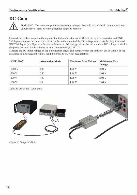
DC-Gain WARNING! The generator produces hazardous voltages. To avoid risk of shock, do not touch any exposed metal parts after the generator output is enabled.
Connect the probe’s output to the input of the test multimeter via 50 Ω feed through its connector and BNC Y-Adapter. Connect the input leads of the probe to the output of the DC voltage source via the fully insulated BNC Y-Adapter (see Figure 2). Set the multimeter to DC voltage mode. Set the source to DC voltage mode. Let the probe warm up for 30 minutes at room temperature (15-35° C). Measure the DC-input voltage in the 4 attenuation stages and compare with the limits set out in table 3. If the measured values exceed the limits send the probe to PMK for recalibration.
KHT1000C Attenuation-Mode Multimter Min. Voltage Multimeter Max. Voltage
1000 V 500 1.96 V 2.04 V
500 V 250 1.96 V 2.04 V
200 V 100 1.96 V 2.04 V
100 V 50 1.96 V 2.04 V
Table 3: List of DC-Gain limits
Figure 2: Setup DC-Gain
15
Performance Verification BumbleBee®
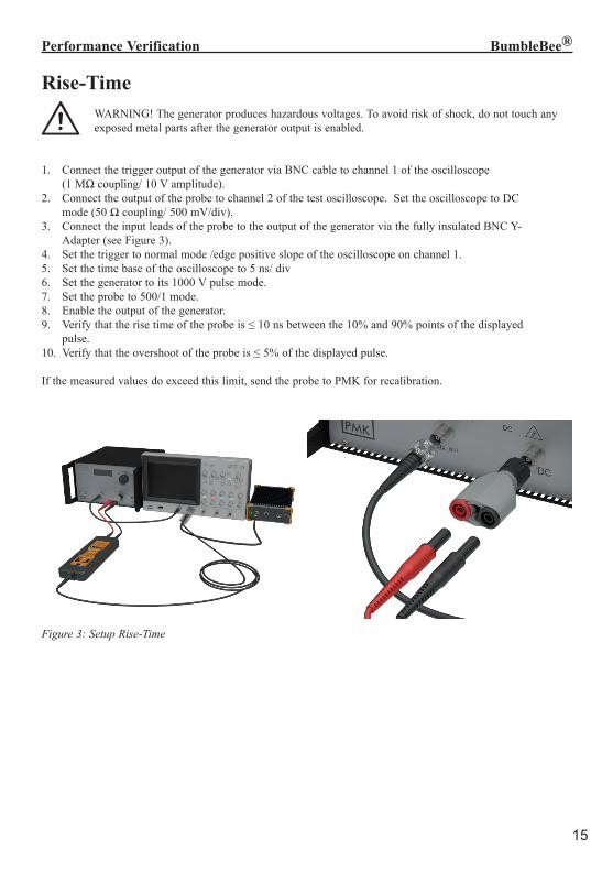
Rise-Time WARNING! The generator produces hazardous voltages. To avoid risk of shock, do not touch any exposed metal parts after the generator output is enabled.
1. Connect the trigger output of the generator via BNC cable to channel 1 of the oscilloscope (1 MΩ coupling/ 10 V amplitude).2. Connect the output of the probe to channel 2 of the test oscilloscope. Set the oscilloscope to DC mode (50 Ω coupling/ 500 mV/div).3. Connect the input leads of the probe to the output of the generator via the fully insulated BNC Y- Adapter (see Figure 3).4. Set the trigger to normal mode /edge positive slope of the oscilloscope on channel 1.5. Set the time base of the oscilloscope to 5 ns/ div6. Set the generator to its 1000 V pulse mode. 7. Set the probe to 500/1 mode.8. Enable the output of the generator.9. Verify that the rise time of the probe is ≤ 10 ns between the 10% and 90% points of the displayed pulse.10. Verify that the overshoot of the probe is ≤ 5% of the displayed pulse.
If the measured values do exceed this limit, send the probe to PMK for recalibration.
Figure 3: Setup Rise-Time
16
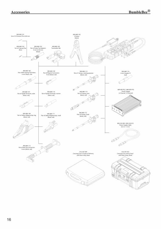
890-880-113Pair of Clamps, rotating grip jaw
(black, red)
890-880-115Pair of Clamps, hook
(black, red)
890-880-114Pair of Clamps, jaws
(black, red)
890-880-1164 mm Coupler f-f
(red)
890-880-109Pair of Magnet Connectors
4 mm (black, red)
890-880-107Pair of Spade Terminals, wide
(black, red)
890-880-110Pair of Spade Terminals, narrow
(black, red)
890-880-111Pair of Safety Alligatorclips, small
(black, red)
890-880-108Pair of Safety Alligatorclips, big
(black, red)
890-880-1052-Footer(black)
890-520-900 / 890-520-915Power Supply Cable
(0.5 m / 1.5 m)
890-880-103Pair of Probe Tip Adapters
4 mm to 0.8 mm (black)
890-880-102Set of 4 Spring Tips
(fine)
890-880-106Pair of Mini Spring Tip Probes
4 mm (black, red)
890-880-112Pair of Rail Clip Connectors
4 mm (black, red)
BumbleBee® Probe Accessories
890-880-104Twinholder M6
890-880-101Set of 10 Contact Pins 0.64 mm
889-09V-PS2 / 889-09V-PS3Power Supply
(2 Channel / 4 Channel)
016-397-055Carrying Case „Heavy Duty“
with foam inlays, black
016-397-049Carrying Case in Scope of Delivery
with foam inlay, black
Accessories BumbleBee®
17
Notes BumbleBee®
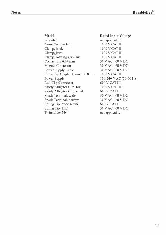
Model Rated Input Voltage 2-Footer not applicable 4 mm Coupler f-f 1000 V CAT III Clamp, hook 1000 V CAT II Clamp, jaws 1000 V CAT III Clamp, rotating grip jaw 1000 V CAT II Contact Pin 0.64 mm 30 V AC / 60 V DC Magnet Connector 30 V AC / 60 V DC Power Supply Cable 30 V AC / 60 V DC Probe Tip Adapter 4 mm to 0.8 mm 1000 V CAT III Power Supply 100-240 V AC /50-60 Hz Rail Clip Connector 600 V CAT III Safety Alligator Clip, big 1000 V CAT III Safety Alligator Clip, small 600 V CAT II Spade Terminal, wide 30 V AC / 60 V DC Spade Terminal, narrow 30 V AC / 60 V DC Spring Tip Probe 4 mm 600 V CAT II Spring Tip (fine) 30 V AC / 60 V DC Twinholder M6 not applicable

18
Notes BumbleBee®

19
Notes BumbleBee®
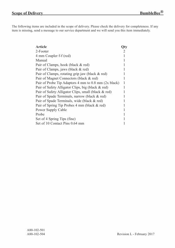
Scope of Delivery BumbleBee®
The following items are included in the scope of delivery. Please check the delivery for completeness. If any item is missing, send a message to our service department and we will send you this item immediately.
Article Qty 2-Footer 2 4 mm Coupler f-f (red) 1 Manual 1 Pair of Clamps, hook (black & red) 1 Pair of Clamps, jaws (black & red) 1 Pair of Clamps, rotating grip jaw (black & red) 1 Pair of Magnet Connectors (black & red) 1 Pair of Probe Tip Adaptors 4 mm to 0.8 mm (2x black) 1 Pair of Safety Alligator Clips, big (black & red) 1 Pair of Safety Alligator Clips, small (black & red) 1 Pair of Spade Terminals, narrow (black & red) 1 Pair of Spade Terminals, wide (black & red) 1 Pair of Spring Tip Probes 4 mm (black & red) 1 Power Supply Cable 1 Probe 1 Set of 4 Spring Tips (fine) 1 Set of 10 Contact Pins 0.64 mm 1
A80-102-501 A80-102-504 Revision L - February 2017