Embed Size (px)
Citation preview

Bulletin of the Seismological Society of America. Vol. 50, No. 4, pp. 553-559. October, 1960
REPORT ON SOME EXPERIMENTAL LONG-PERIOD SEISMOGRAPHS
By RALP~ GILMAN
ABSTRACT
The unexpected usefulness in research of the Press-Ewing seismograph system (Press, Ewing and Lehner, 1958) has stimulated further efforts to obtain even higher seismograph sensitivity in the period range beyond 100 see. A major difficulty has been in maintaining pendulum stabil- ity at long periods. This paper describes a stable long-period seismometer and gives results from several se, ismograph systems incorporating long-period pendulums and galvanometers.
A PERIOD LENGTHENING DEVICE
IN ORDER to improve pendulum behavior, auxiliary restoring forces are used in addition to those due to springs and gravity. This method, here applied to an ordinary horizontal pendulum, takes the form of a pair of moving coil transducers of the type commonly used as velocity sensors in seismometers.
As shown in figure 1, the transducers are arranged so that the coils are attached to opposite sides of the pendulum mass and the permanent magnets are fixed to the instrument frame. A constant current is passed through the coils which are con- nected in series (figure 2), and polarized to produce restoring forces on the mass opposite in direction to the restoring forces due to gravity. This results in a lengthened period.
Since the coil current is constant and the magnetic field strength is uniform along the axis of the pole piece, the resulting force is very nearly proportional to the penetration of the coil in the gap. In this way an approximately linear relationship between force and displacement is achieved.
The total current is regulated by a variable resistor and provides for period ad- justment. The amount of current passing through each coil is regulated by a balanc- ing potentiometer and affords a convenient centering system. Coil current of 200 u A is sufficient to lengthen the pendulum period from 20 sec. to 100 see. Constant coil current is assured by using mercury batteries.
An important advantage of this system arises from the possibility of using remote controls so that centering, period adjustments and tests may be made without disturbing the instrument.
Although the mass and boom were made from high grade electrolytic copper, the presence of magnetic impurities in these parts contributed to instability at periods of about 100 sec. In addition to instability, the effect manifests itself by producing a dependence of free period on amplitude.
To correct this condition, the pole pieces of the auxiliary transducers were tapered outwardly toward the direction of greater boom deflection. Nonlinear restoring forces are thus provided, opposite in sense to those caused by magnetic contamination. The test for proper compensation is independence of free period on amplitude. Excellent seismometer behavior is thus achieved, operating periods being limited by ground stability. Test oscillations of 180 see. have been produced in the vault of the Seismological Laboratory at Pasadena. Ground tilts from earth
Manuscript received for publication March 17, 1960.
553
5 5 4 BULLETIN OF THE SEISMOLOGICAL SOCIETY OF AMERICA
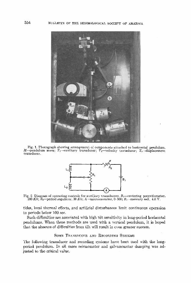
Fig. 1. Photograph showing arrangement of components attached to horizontal pendulum. M--pendulum mass; Tl--auxiliary transducer; T2--veloeity transducer; T~--displacement transducer.
Fig. 2. Diagram of operating controls for auxiliary transducers. Rl--centering potentiometer, 100 K~; R2--period regulator, 30 K~; A--microammeter, 0-500; Bl--mercury cell, 4.0 V.
tides, local thermal effects, and artificial disturbances limit continuous operation to periods below 100 see.
Such difficulties are associated with high tilt sensitivity in long-period horizontal pendulums. When these methods are used with a vertical pendulum, it is hoped tha t the absence of difficulties from tilt will result in even greater success.
SOME TRANSDUCER AND RECORDING SYSTEMS
The following transducer and recording systems have been used with the long- period pendulum. In all cases seismometer and galvanometer damping was ad- justed to the critical value.
EXPERIMENTAL LONG-PERIOD SEISMOGRAPHS 555
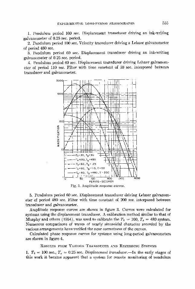
1. Pendulum period 100 sec. Displacement transducer driving an ink-writlng galvanometer of 0.25 sec. period.
2. Pendulum period 100 see. Velocity transducer driving a Lehner galvanometer of period 480 see.
3. Pendulum period 60 see. Displacement transducer driving an ink-writing galvanometer of 0.25 sec. period.
4. Pendulum period 60 sec. Displacement transducer driving Lehner galvanom- eter of period 110 sec. Filter with time constant of 50 see. interposed between transducer and galvanometer.
PERIOD-SECONDS
Fig. 3. Ampl i tude response curves.
00
5. Pendulum period 60 sec. Displacement transducer driving Lehner galvanom- eter of period 480 sec. Filter with time constant of 200 see. interposed between transducer and galvanometer.
Amplitude response curves are shown in figure 3. Curves were calculated for systems using the displacement transducer. A calibration method similar to that of Murphy and others (1954), was used to calibrate the To = 100, T~ = 480 system. Numerous comparisons of waves of nearly sinusoidal character recorded by the various arrangements have verified the near correctness of the curves.
Calculated phase response curves for systems using long-period galvanometers are shown in figure 4.
RESULTS FROM VARIOUS TRANSDUCER AND RECORDING SYSTEMS
1. To = 100 sec., T~ = 0.25 sec. Displacement transducer.--In the early stages of this work it became apparent that a system for remote monitoring of pendulum

556 BULLETIN OF THE SEISMOLOGICAL 8OCIETY OF AM]!IRIC_&
position would be required. A displacement transducer which provides a voltage output proportional to mass position was installed and coupled with a recorder using an ink-writing galvanometer of period 0.25 sec., and paper speed 0.75 inch per hour. Pendulum period was adjusted to 100 sec. Figure 5 reproduces a trace taken from this recorder. Ground tilt due to earth tides is recorded together with two large earthquakes (14 Sept. 1959; 14:00:39; 28½ S, 177 W; M = 7¼:15 Sept. 1959; 05:29:42; 28½ S, 177 W; M = 6~).
Although this recorder was installed to check pendulum centering, its low peak magnification of 75 provided a convenient means for estimating the magnitudes of large earthquakes which otherwise would be off scale.
3 7r/a . . . . . .
w ",
~-7r/2
o ¢L
"rr/2,io ,~o
Fig. 4.
I I ~ ] 7 1 t I I
~- -~To= 60, Tg = 4-80, T= 200
I / / I /L ...... TO:60 , Tg : I ]O, "C: 50 L_.
I ~ J / l l . . . . . . To =100, Tg =480 /
kl ] ~ ' L - - ' - - T° = ~0 ' Tg=90 / I'N H~",.
I00 400 I000 4000 PERIOD-SECONDS
P h a s e r e sponse cu rves .
Fig. 5. Trace from ink-writing gulvanometer recorder.
2. To = 100 sec., Tg = 480 sec. Velocity transducer.--In addition to the dis- placement transducer, a moving coil velocity transducer was coupled with the newly developed Lehner ultra-long-period galvanometer (Lehner, 1959).
A sample recording (figure 6) shows a seismogram of an earthquake with a long continental path to Pasadena (29 August 1959; 17:03:10; 52 N, 106½ E; M = 6½). Comparison is made with the Press-Ewing seismograph; To = 30, Tg = 90 (lower trace). Each instrument is E-W in response, with drive speeds and time in agree- ment. The upper recording alone shows the initial 120 sec. oscillation of the Love waves. It also indicates dispersion more clearly because of the reduced contamina- tion from shorter period waves.
3. To = 60, Tg = 0.25. Displacement transducer.--To avoid drift problems inherent with long-period horizontal pendulums, the period was reduced to 60 see., at which value it now operates. Reduced tilt sensitivity allowed the peak magnifi-

EXPERIMENTAL LONG-PERIOD SEISMOGRAPHS 557
cation to be raised from 75 to 170. Response to tidal tilt is about the same as before the pendulum period was shortened.
4. To = 60, T~ = 110, ~ = 50. Displacement Transducer.--In order to regain long-period sensitivity lost by reducing the pendulum period, the displacement transducer is now used with long-period galvanometers.
Unfiltered amplitude attenuation of this system is 6 db per octave in the period range greater than the galvanometer and seismometer period, as compared to 9 db per octave for the velocity coupled system. In systems with high magnification, large drifts caused by tidal tilt make it necessary to introduce a passive filter
LOVE I > !
Fig. 6. Comparison of seismograms from Fress-Ewing seismograph (lower trace) and seismo- graph with constants To = 100 seconds, To = 480 seconds.
~ o n e min.
s Ps ss sss 6 R
Fig. 7. Comparison of seismograms from Press-Ewing seismograph (lower trsce) and seismo- graph with constants To = 60 seconds, T~ = 110 seconds, r = 50 seconds.
between the transducer and the galvanometer. This filter has the form of a resistor and capacitor connected in series. The filter time constant, r, is kept as large as possible consistent with conditions of noise and drift. The displacement transducer now drives three parMleled galvanometers.
For high mid-range response the 110 sec. galvanometer with T = 50 sec. is ad- justed to peak magnification of 2200. Greater magnification is restricted by high noise in the range of peak response. Figure 7 shows a sample recording from this combination. Again comparison is made with the Press-Ewing seismograph (lower trace). A~ maybe expected from examination of the response curves, this arrange- ment gives unusually good results for G and the longer period crustal and mantle Rayleigh waves. The seismograms reproduced are of an earthquake with a long oceanic path to Pasadena (21 Dec., 1959; 10:20:33; 23½ S, 176 W; M = 6). Of interest is the inverse dispersion in R1, starting with the group velocity maximum

558 BULLETIN OF THE SEISMOLOGICAL SOCIETY OF AMERICA
for oceanic crustal Rayleigh waves at 40 sec. and merging with the mantle Rayleigh waves. Until recently it was believed that long-period mantle Rayleigh waves were initiated only by shocks greater than 7¼ magnitude (Ewing and Press, 1956). The transient nature of G is cleazly evident in the upper recording and almost absent on the lower recording.
5. To = 60, Tg = 480, r --- 200. Displacement transducer.--Ultra-long period response is achieved by using the Lehner ultra-long-period galvanometer of •period 480 sec. Coupling to the displacement transducer is through a filter with r = 200
s t
To = 30 , T g = 9 0
To=60, Tg=l lO, " [ ' = 5 0
I
S S
, ! , i R ,1, A sss
I • I
To = 60, T~ = 480, T = 2OO K ,..~, /
OB 5 ~ '
Fig, 8. Comparison of seismograms from Press-Ewing seismograph; seismograph wi th con- stants To = 60 seconds, To = 110 seconds, r = 50 seconds; 9,rid seisinogrs, ph wi th constant To = 60 seconds, Tg = 480 seconds, • = 200 seconds.
sec. High noise from artificial and barometric sources limits peak magnification to only 300. A sample recording is included in figure 8 (lower trace).
Three seismograms from the earthquake of 4 February 1960 are compared for the purpose of demonstrating the usefulness of long-period seismographs in the study of body waves. The upper recording reveals the usual body waves with no hint of component periods greater than 30 sec. in the P phase and 60 sec. in the S phases. Further, the time interval between PP and S shows no distinct phases. On the other hand, the lower recordings show component periods up to 200 sec. and a dis- tinctive event is present between FF and S. Note the simplicity of the body phases on the two lower seismograms. It may well be that long-period seismographs can provide as much or more information about the mechanism at the focus as short period instruments.
EXPERIMENTAL LONG-PERIOD SEISMOGRAPHS 559
There is much current interest in experimental observations of the free modes of vibration of the earth. The instrument here described may be able to record such vibrations if they are sufficiently large. For periods of 40 minutes it is 100 times more sensitive than the Press-Ewing seismograph for example. Recently, ultra-long pe1~od waves were recorded following the earthquake of 13 January 1960, 15:40:34. These waves are now being studied to see if they are free vibrations of the earth and a report on this work will appear shortly.
CONCLUSIONS
Ultra-long-period seismographs are regularly providing new data and show the desirability for continued operation and improvement of such systems.
The use of displacement transducers together with long-period galvanometers for efficient extraction of long-period signals is clearly demonstrated.
Problems of noise remain to be solved. Further progress, apart from improvement in instrument reliability, will lie in the reduction of the effects from background vibrations.
ACKNOWLEDGEMENTS
The author is grateful to Dr. Frank Press for guidance and encouragement in carrying out these experiments. Mr. J. L. Blayney designed and built the displacement transducer.
REFERENCES
Ewing, Maurice and Frank Press 1956. "Rayleigh Wave Dispersion in the Period Range 10-500 Seconds," Trans.
Am. Geophys. Union, 37: 213-215. Lehner, Francis E.
1959. "An Ultra Long-Period Seismograph Galvanometer," Bull. Seism. Soc. Am., 49: 399- 401.
Murphy, L. M., R. M. Wilson, L. R. Burgess and T. H. Pearce 1954. "Response Curves of an Electromagnetic Seismograph by Sine Wave Simulator
Method," Bull. Seism. Soc. Am., 44: 7-19. Press, Frank, Maurice Ewing and Francis Lehner
1958. "A Long-Period Seismograph System," Trans. Am. Geophys. Union, 3g: 106--108.
SEISMOLOGICAL LABORATORY, CALIFORNIA INSTITUTE 01~ TECHNOLOGY~ PASADENA j CALIFORNIA. (Division of the Geological Sciences, contribution no. 974.)