Embed Size (px)
Citation preview

Small Tool Instruments and Data Management
Bulletin No. 1954
New wireless system improves efficiency by eliminating the need for data cables when sending measurements to a PC
U-WAVE®Measurement Data Wireless Communication System

U-WAVE®Measurement Data Wireless Communication System
The U-WAVE system enables easy wireless data communication from a measuring tool to a PC using the Digimatic protocol. Measurement efficiency is improved by eliminating the long and cumbersome data cables. The user-friendly interface allows data to be loaded into any software product that accepts keyboard input, such as Excel* or Notepad.
U-WAVE-R
U-WAVE-T
Easy loading in Excel format
The U-WAVEPAK, U-WAVE-R standard package features a keyboard interface function. This allows measurement data to be easily entered into in Excel, Notepad or other format that accepts numeric value input via a keyboard.
Approximately 400,000 Data Transmissions
One commercially available CR2032 lithium battery will support about 400,000 data transmissions.Assuming that the device is used twenty days a month, sending data 2,000 times a day, one battery will last for about ten months.
In addition, a virtual COM driver allows measurement data to be input to a program that supports RS-232C serial communication. The communication speed (baud rate) is fixed to 57,600 bps.
Dustproof and waterresistant IP67 model
Note: In accordance with wireless regulations the use of this product is permitted in Japan, Europe (a total of 32 countries including 27 EU members, 4 EFTA members and Turkey), U.S.A. and Canada. This product must not be used in other countries or areas.
U-WAVE-R loads data received from U-WAVE-T onto a PC software package via a USB port
U-WAVE-T units transmit data from measuring tools to U-WAVE-R
2
IP67-type U-WAVE-T (No.02AZD730C) has an IP67-level dust/water-proof function. This model can be used in combination with, devices such as a coolant-proof caliper, micrometer or indicator.
*Excel is a registered trademark of Microsoft Corporation.
Easy loading in Excel format Dustproof and waterresistant IP67 model
Approximately 400,000 Data Transmissions
Measurement data can be entered into a software package
other countries or areas.
U-WAVE-T

3
U-WAVE®
Up to 100 measuring tools can be connected to one U-WAVE-R unit
Up to 100 U-WAVE-T units can be registered with one U-WAVE-R unit, and up to 16 U-WAVE-R units can be connected via a commercially available USB hub.
MUX-10F(up to 4 wired channels)
U-WAVE(up to 100 wireless channels)
Scalability for measuring tool expansion
ID=00 ID=01 · · · · · · · · · · · · · ID=99
Up to 16 U-WAVE-R units can be connected to one PC
Data communication range up to 60ft possible
The maximum reliable communication range is approximately 60ft*. Even when multiple U-WAVE-R units are used within the range of 60ft, interference does not occur since an ID (00 to 99) is assigned to each unit. Radio interference between U-WAVE-Runits can also be avoided by setting different frequencies (selected from 15 bands).*Actual range depends on the local radio transmission characteristics.
Different frequencies ensure no radio interference
60ft
Design enhancements offer a variety of funtional improvements and a price lower than existing Mu-WAVE models.
Measurement on surface plateWith a cordless device, the surface plate and PC desk no longer need to be adjacent, allowing flexible layout in the inspection room.
Measurement of large workpiecesWith U-WAVE, operators can perform measurement freely around the workpiece with no cable constraints.
Measurement using long measuring toolsU-WAVE eliminates cable constraints, making the use of hard-to-handle, long measuring tools easier.
Up to 100 tools can transmit to each U-WAVE-R
Frequency: 2.405 GHz
60ft
ID=00
ID=99
ID=99
A 4-digit value in **** indicates a U-WAVE-T ID.
0 0 9 9
0 0 0 0
0 1 0 0
0 1 9 9
ID=00 ID=01ID=00
Different frequencies allow multiple devices to be used in the same communication range.
Up to 100 measuring tools can be connected to one U-WAVE-R unit
Cordless operation improves efficiency in measurement data recording
Data communication range up to 60ft possible
Lower price than existing Mu-WAVE models
Frequency: 2.475 GHz
Cordless operation improves efficiency in measurement data recording
Lower price than existing Mu-WAVE models

Just press a button to send measurements to Purchase the following four products ( 1 to 4 ) to send data to your PC.
4 Mitutoyo Measuring Tool with Digimatic OutputThis product can be connected to a measuring tool that provides Digimatic data output. Digimatic output is Mitutoyo's proprietary output format. The Digimatic specifications remain unchanged since the first Digimatic measuring tool was released. Therefore, any tool having a Digimatic port can be used, regardless of age. Connectors on some older instruments are not compatible with connectors used on the above-listed cables. See cable list on page 7.
Super CaliperCD67-S15PMNo.02AZD790A
QuantuMikeMDE-25MJNo.02AZD790B
ABS Digimatic CaliperCD-15CXNo.02AZD790C
4
2 U-WAVE-TU-WAVE-T sends measurement data to U-WAVE-R.
Model U-WAVE-T (IP67 model)
Order No. 02AZD730C*Protection Rating IP67
Data receptionindication LEDs
Power supply Lithium battery CR2032 x 1
Battery life Approx. 400,000transmissions
Externaldimensions
1.73" x 1.17" x .73"(44 x 29.6 x 18.5 mm)
Mass .05 lbs (23g)
Major specifications of U-WAVE-TActual size
Standard accessory: driver
· Registered Design (Japan)3 U-WAVE-T/tool connectionA short cable is used to connect a measuring tool to its U-WAVE-T unit. Select the appropriate cable from Ato G below (7 types) to suit the measuring tool. Detailed information on cable suitability is given on page 7.
AFB
C D E
G
Cable length: 6.30"
(160 mm)
Cable with clip
Fasteningclip included with cable
Type Order No.A Water-proof model with output button 02AZD790AB Water-proof model with output button 02AZD790BC With data-out button type 02AZD790CD 10-pin plain type 02AZD790DE 6-pin round 02AZD790EF Plain type straight 02AZD790FG Plain type straight water-proof model 02AZD790G
ol with Digimatic Output
U-WAVE-T
U-WAVE-Tconnecting cable
Measuring Tool with Digimatic Output
DigimaticIndicatorID-H0530No.02AZD790D
Example Digimatic measuring tools pictured with connecting cables. Instrument models/cable product numbers are listed below.
*Detailed information on conformity standards of wireless communication specification is given on page 6.
Inch/(Metric)

5
U-WAVE® a PC through wireless communication.
Quick MicroMDQ-30MNo.02AZD790E
DigimaticHeight GaugeHD-30AXNo.02AZD790F
ABS DigimaticIndicatorID-N112No.02AZD790G
When the data input button is pressed, the value displayed on the measuring tool is entered into the active cell of Excel followed by “Enter” key input. The cursor movement direction after input (up, down, left or right) can be set in Excel.
Once the U-WAVEPAK data interface function has been started, received data is converted into a keyboard input and entered into the active cell.
U-WAVE-R main unit
USB 2.0 cable 39.40" (1 m)
Standard U-WAVEPAKsetup software
Wall installation board
· Registered Design (Japan)
Communication distance of approximately 60ft (in a good transmission/reception location)
1 U-WAVE-R
Model U-WAVE-ROrder No. 02AZD810C*
Power supply USB bus power systemNumber of U-WAVE-Runits that can beconnected to one PC
Up to 16
Number of U-WAVE-Tunits that can be connected Up to 100
External dimensions 5.51" x 3.15" x 1.24" (140 x 80 x 31.6mm)Mass .29 lbs (130g)
Major Specifications of U-WAVE-R
*Detailed information on conformity standards of wireless communication specification is given on page 6.
*Refer to page 6 for specification of U-WAVEPAK (setup software)
*Refer to page 6 for wireless communication specificationInch/(Metric)

6
Conformity standards
·European conformity standards* EN 50371:2002 EN 300 440-1 V1.3.1 EN 300 440-2 V1.1.2 EN 301 489-01 V1.6.1 EN 301 489-03 V1.4.1·U.S.A. conformity standards 47 CFR Part 15.247:(Subpart :C) 47 CFR Part 15,(Subpart :B)·Canada conformity standards RSS-210 (Issue 7) RSS-Gen (Issue 2) ICES 003 (Issue 4)
Wireless standards Conform to IEEE802.15.4Wireless communication distance Approx. 60ft (within visible range)Wireless communication speed 250 kbpsTransmission output 1 mW (0 dBm) or lessModulationmethod
DS-SS (direct sequence spread spectrum)Resistant to interfering signal or noise.
Communicationfrequency
2.4 GHz band (ISM band: universal frequency)
Used band
15 channels (2.405 to 2.475GHz at intervals of 5MHz)The noise search function can avoid interference with other communication devices.
Specifications of wireless communication
Note: In accordance with wireless regulations the use of this product is permitted in Japan, Europe (a total of 32 countries including 27 EU members, 4 EFTA members and Turkey), U.S.A. and Canada. This product must not be used in other countries or areas.
· This product is not compatible with the conventional Mu-WAVE, for which communication specifications are different.* Japan conformity standards: ARIB STD-T66
<Specifications of U-WAVEPAK (setup software)>Before using U-WAVEPAK for the first time, IDs, frequencies, and other software setup must occur. The data interface function allows measurement data to be sent to a PC into Excel, Notepad or other software that accepts keyboard input.Data can also be sent to a program that supports RS-232C serial communication using the virtual COM driver.
1) Operating environmentSupported OS: Windows 2000 Professional (SP4 or higher)
Windows XP Home Edition (SP2 or higher)Windows XP Professional (SP2 or higher)Windows Vista
Other information: USB port needed2) Initial setup procedure(1) Install U-WAVEPAK (setup software).(2) Connect the U-WAVE-R main unit to the PC with a USB 2.0 cable.(3) Install the dedicated USB driver and virtual COM driver.(4) Set IDs and frequencies for U-WAVE-R and U-WAVE-T with
U-WAVEPAK.(5) Press the DATA button of U-WAVE-T once to write settings
into U-WAVE-T main unit memory.
3) Data interface functionData is entered into an Excel or Notepad file as keyboard-input data.(1) Control key (terminal code)Codes to be suffixed to measurement data can be switched.· ENTER (default), TAB, up, down, left, right
(2) Data send modeTwo data formats are available.· Measurement data only (default) Example +00000012.34· All data Example DT1 01 02 +00000012.34 M Header: measurement data Measurement dataU-WAVE-R ID: 00 to 99 Unit M: millimeter
U-WAVE-T ID: 00 to 99 I: inch
(3) Use of status codeSelect the state of U-WAVE or whether to output control command or other data.· Ignore (default), loadStatus code: low battery voltage (00), no response from measuring tool (01), measurement data missing (03), data cancellation (99), etc. Example data cancellation ST1 01 02 0999999073 99 Header: status Device ID*
U-WAVE-R ID: 00 to 99 Status codeU-WAVE-T ID: 00 to 99 99: data cancellation
*Unique number assigned to U-WAVE-T and WAVE-R at shipment
Receives data from U-WAVE-T and sends it to a PC via a USB connection
U-WAVE-R

7
U-WAVE®List of U-WAVE-T Connecting Cables
From seven types of cables (A to G ), select one compatible with your measuring tool.
Cable type Awater-proof model with output button B water-proof model
with output button C With data-out button type D10-pin plain type E 6-pin round F Plain type straight G Plain type straight
water-proof modelOrder No. 02AZD790A 02AZD790B 02AZD790C 02AZD790D 02AZD790E 02AZD790F 02AZD790G
Connector shapeon the measuringtool side
Socketshape on the measuringtool
[Digimatic Caliper] [Digimatic Micrometer] [Digimatic Caliper] [Digimatic Indicator] [Digimatic Micrometer] [Digimatic Caliper] [Digimatic Indicator]CD67-S_PM MDE-MJ CD-CX/-C ID-H/F MDQ-M CD, CFC-P/-L/-C/-U ID-NCD-PMX MDC-MJ/MJT CD-S_C [Linear Height] MDC-M [Digimatic Height Gages] ID-BCD-PM/GM [Digimatic Micrometer] CDC-CX/C QMH-S CLM1-QM/DK HD-AX, HDM-AXCDC-P_PMX The code suffix is -MJ. CDN-CX/C [Linear Gage/Counter] PDM-QM HDS-H_C/-C
Codesof major compatiblemeasuringtools and instruments
CDN-P_PMX BLM-M [Digimatic Caliper] EB,EC-D PMU-DM HDM-ACFC-G/GL/GC/GU OMV-M NTD-CX/C [μ-checker] BD-M HDF-N[Digimatic Caliper] OMP-M [Digimatic Depth Gage] Digital μ-checker [Digimatic Holtest] [Digimatic Indicator]NTD-PMX PDM-M VDS-DCX [Laser Scan Micrometer] HTD ID-C/_RB/_A/_GB[Digimatic Depth Gage] IMP-M [Digital Scale and LSM-9506 [Reference Gage] ID-S/UVDS-PMX VM-M DRO Systems] [Reference Gage] HDM-DM [Digimatic Depth Gage][Digital Scale and [Digimatic Micrometer Heads] SD-D, SDV-D HDM-C [Hardness Testing Machines] Digimatic model (ID-C) DRO Systems] MHN-M/MJ/MJN [Coating Thickness Gage] HM-100/200 [Digital Scale and SD-G [Digimatic Holtest] DGE-745/755 HV-100 DRO Systems]
HTD-R [Form Measurement] HR-500 SD-E, SDV-E[Digimatic Depth Gage] SJ-201/301/401 HH-411 SD-F, SDV-FDMC-M [Portable Hardness
Testing Instruments]HH-300
Reference Order No. of connecting cable
1m 05CZA624 05CZA662 959149 936937 937387 905338 21EAA1942m 05CZA625 05CZA663 959150 965014 965013 905409 21EAA190
Cautions · Safety Caution: Do not use this device near medical equipment that might malfunction due to radio interference.· Caution on radio law:This device is certified as a 2.4 GHz band wide-band low-power data communication system based on the Radio
Regulations in Japan, Europe, U.S.A. and Canada. It is prohibited by law to disassemble or modify this device or peel off the certification label from it.
Note on Wireless Communication EnvironmentAlthough the communication range for U-WAVE is approximately 60ft line-of-sight, performance may be affected by obstacles or environmental factors.
Name and Dimensions of Each Part
Item Contents
Concrete wall Communication is not possible into a room completely enclosed.
Metal partition Communication speed may drop or communication may be interrupted.
Wireless LAN, communication device such as ZigBee Bluetooth, and microwave oven
Communication speed may drop or communication may be interrupted. Maintain the set frequency and installation distance if at all possible.
Medicalinstrument
Do not use this product near a medical instrument such as a laser knife or electronic scale.
Items that may cause communication errors
Unit: Inch/(mm)
Light gray Light gray
(red LED)ERROR(green LED)POWER
USB connector
INIT. switch
Certification labelDevice ID label
5.51” (140)
1.24”
(31.6)
3.15
” (8
0)
LED display
Certification label
Device ID label
Connector cover
Battery cover
.73”
(18.
5).6
5” (1
6.6)
1.73”(44)
1.17
”(2
9.6)
U-WAVE-RU-WAVE-T
6.30” (160)
Fasten the connector to U-WAVE-T with two screws.
U-WAVE-TMeasuring toolSelect one from cables A to G, referring to the part number of connecting cable for wired connection in your measuring tool catalog or manual. If you are unsure which cable is appropriate, check the cable connectors, the shapes of terminal on the measuring tool side, or the codes of compatible measuring tool for cables A to G below.It is not possible to connect to EF and EH counters.

MeasurLink® V6.1Combining the U-WAVE system with commercially available data measurment software allows the user to perform SPC and data analysis. New functions have been added to MeasurLink including U-WAVE ID identification and data cancellation.
8
Measurement Data Network System — MeasurLink® V6.1 Real-Time PLUS
Other Highlights
series, tendency, etc.
measured value, etc.
add history information (such as inspector, machine tool, lot number, serial number, and cause of failure) to data as comment so that it can be checked when a problem occurs or used as a keyword to search for or narrow down data.
It is necessary to upgrade to V6.1 to support data cancellation and other new functions of the U-WAVE.The V6.1 upgrade for V6.0 users is at no cost. A service pack can be downloaded from the Support section of the MeasurLink website. www.measurlink.com
Association between U-WAVE-T ID and the Measured ItemWhen there is a one-to-one relationship between the measuring tool and the measured item, data randomly measured by the operator can be automatically input into the associated measured item. When a single measuring tool measures multiple items, determine the measurement order in advance since a single ID cannot identify measured items.
V6.0 or earlier version
When data is input, MeasurLink displays a variety of statistical processing results including GO/NG judgment, process capability, Xbar-R control chart and histogram on the screen in real time.For details, refer to Bulletin No. 1717. Measurement
Xbar-R control chart, Xbar-S control chart, X-Rs control chart, histogram, tier chart, run chart, pre-control chart, statistics, etc. (All selectable)
9
U-WAVE®
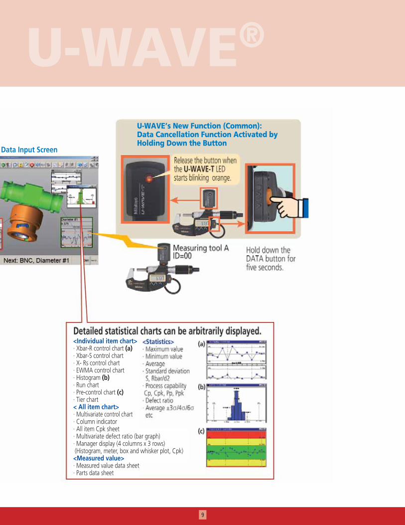
U-WAVE’s New Function (Common): Data Cancellation Function Activated by Holding Down the Button
Data Input Screen
<Individual item chart>· Xbar-R control chart (a)· Xbar-S control chart· X- Rs control chart· EWMA control chart· Histogram (b)· Run chart· Pre-control chart (c)· Tier chart< All item chart>· Multivariate control chart· Column indicator· All item Cpk sheet· Multivariate defect ratio (bar graph)· Manager display (4 columns x 3 rows) (Histogram, meter, box and whisker plot, Cpk)<Measured value>· Measured value data sheet· Parts data sheet

Operating Environment (Recommended)
Central Management of Quality Information through Construction of Measurement Data Network System
MeasurLink Process Analyzer MeasurLink Process Manager
Process monitoring
Data acquisition
Data acquisition
MeasurLink STATMeasure Plus
MeasurLink Real-Time Plus
Process analysis
Factory/quality control
Factory/shop floor
Centralizedmanagement
Database server
LAN
Office
Machiningshop floor
Inspectionroom
Data distributed across the factory can be consolidated.
U-WAVE-T
U-WAVE-R
MeasurLink can be expanded to a network system of server and clients. This software consolidates and centrally manages measurement data generated across the factory (handheld measuring tools to CMMs) to support quality information sharing.
<MeasurLink V6.1 Real-Time PLUS>
OS: Windows 2000/XP VistaCPU: Pentium IV 1GHzMemory: 1 GB or moreHard disk: 2 GB or more free spaceI/O: USB port (required for U-WAVE-R connection)Media drive: CD-ROM (required at installation)
10

11
U-WAVE®PDA NaviRemotely view data input into MeasurLink Real-Time Plus (sold separately)
PDA Navi is a measurement navigation program that allows data input to MeasurLink Real-Time Plus on a PC to be viewed using a commercially available PDA* via a wireless LAN. This means that even when you make measurements at a station remote from your PC the measurement data can still be sent to the PC with U-WAVE, loaded into MeasurLink and the results fed back to PDA Navi for viewing at your remote station. GO/NG judgment results, statistical processing results, next point to be measured and other data can all be verified.
Measurement Navigation Program — PDA Navi
Operating Environment for PDA NaviSupported OS Microsoft Windows Mobile 5.0 for Pocket PC
Supported PDAPDA equipped with above OS and wireless LANRecommended memory: ROM: 192 MB or more, RAM: 64 MB or moreCertified model: “iPAQ hx 2490b2” (from HP)
SupportedMeasurLink
Real-Time Plus or STAT-Measure Plus V6.1 or higher (required when using PDA Navi)
Major Specifications of PDA Navi
color-coded.
Chart display: control chart, histogram, run chart, etc.
serial number
WirelessLAN-
equippedPDA
PDA Navi
* PDA stands for Personal Digital Assistant and refers to a personal mobile information terminal.
**PDA device not included
Measured items and instructions for this measurement
Communication range: approximately 60ft (line of sight)
PDA Navi Measurement Screen Example
Order No. 64AASPDAN**

Aurora, Illinois(Corporate Headquarters)
Westford, Massachusetts
Huntersville, North Carolina
Mason, Ohio
Plymouth, Michigan
City of Industry, California
One Number to Serve You Better1-888-MITUTOYO (1-888-648-8869)
Note: All information regarding our products, and in particular the illustrations, drawings, dimensional and perfor-mance data contained in this printed matter as well as other technical data are to be regarded as approximate average values. We therefore reserve the right to make changes to the corresponding designs. The stated standards, similar technical regulations, descriptions and illustrations of the products were valid at the time of printing. In addition, the latest applicable version of our General Trading Conditions will apply. Only quotations submitted by ourselves may be regarded as definitive.
Mitutoyo products are subject to US Export Administration Regulations (EAR). Re-export or relocation of Mitutoyo prod-ucts may require prior approval by an appropriate governing authority.
Trademarks and RegistrationsDesignations used by companies to distinguish their products are often claimed as trademarks. In all instances where Mitutoyo America Corporation is aware of a claim, the product names appear in initial capital or all capital letters. The appropriate companies should be contacted for more complete trademark and registration information.
We reserve the right to change specifications and prices without notice.