Embed Size (px)
Citation preview
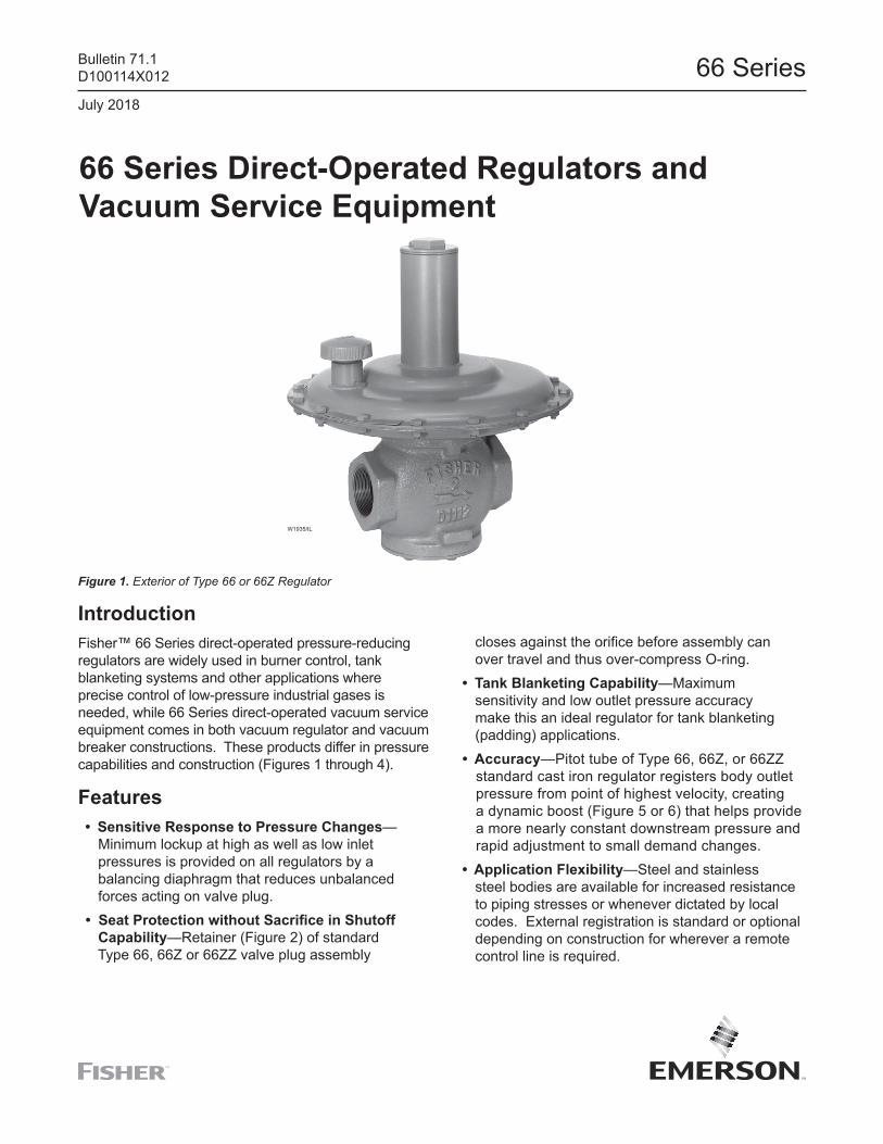
66 Series Direct-Operated Regulators and Vacuum Service Equipment
IntroductionFisher™ 66 Series direct-operated pressure-reducing regulators are widely used in burner control, tank blanketing systems and other applications where precise control of low-pressure industrial gases is needed, while 66 Series direct-operated vacuum service equipment comes in both vacuum regulator and vacuum breaker constructions. These products differ in pressure capabilities and construction (Figures 1 through 4).
Features • Sensitive Response to Pressure Changes— Minimum lockup at high as well as low inlet pressures is provided on all regulators by a balancing diaphragm that reduces unbalanced forces acting on valve plug. • Seat Protection without Sacrifice in Shutoff Capability—Retainer (Figure 2) of standard Type 66, 66Z or 66ZZ valve plug assembly
closes against the orifice before assembly can over travel and thus over-compress O-ring. • Tank Blanketing Capability—Maximum sensitivity and low outlet pressure accuracy make this an ideal regulator for tank blanketing (padding) applications. • Accuracy—Pitot tube of Type 66, 66Z, or 66ZZ standard cast iron regulator registers body outlet pressure from point of highest velocity, creating a dynamic boost (Figure 5 or 6) that helps provide a more nearly constant downstream pressure and rapid adjustment to small demand changes. • Application Flexibility—Steel and stainless steel bodies are available for increased resistance to piping stresses or whenever dictated by local codes. External registration is standard or optional depending on construction for wherever a remote control line is required.
Figure 1. Exterior of Type 66 or 66Z Regulator
W1935/IL
Bulletin 71.1D100114X012
July 2018
66 Series
Specifications
1. The pressure/temperature limits in this Bulletin and any applicable standard or code limitation for valve should not be exceeded.
Maximum Allowable Inlet Pressures(1)
Emergency Inlet Pressure: Type 66, 66Z, 66ZZ or 66 Series Vacuum Breakers: 25 psig / 1.72 bar positive pressure 66 Series vacuum regulators: 8 psig or 16.3 in.
of mercury / 0.55 bar d vacuum Maximum Safe Pressure to Avoid Internal Parts Damage: Type 66: 10 psig / 0.69 bar Type 66Z: 5 psig / 0.34 bar Type 66ZZ: 2 psig / 0.14 bar 66 Series Vacuum Regulators or Breakers: no more than 1 psig / 0.07 bar d change from spring setting Maximum Operating Inlet Pressure Recommended for Good Performance: Type 66, 66Z or 66 Series Vacuum Breakers: 5 psig / 0.34 bar positive pressure Type 66ZZ: 2 psig / 0.14 bar 66 Series Vacuum Regulator: 6 in. w.c. or 0.4 in. of mercury / 15 mbar d vacuum
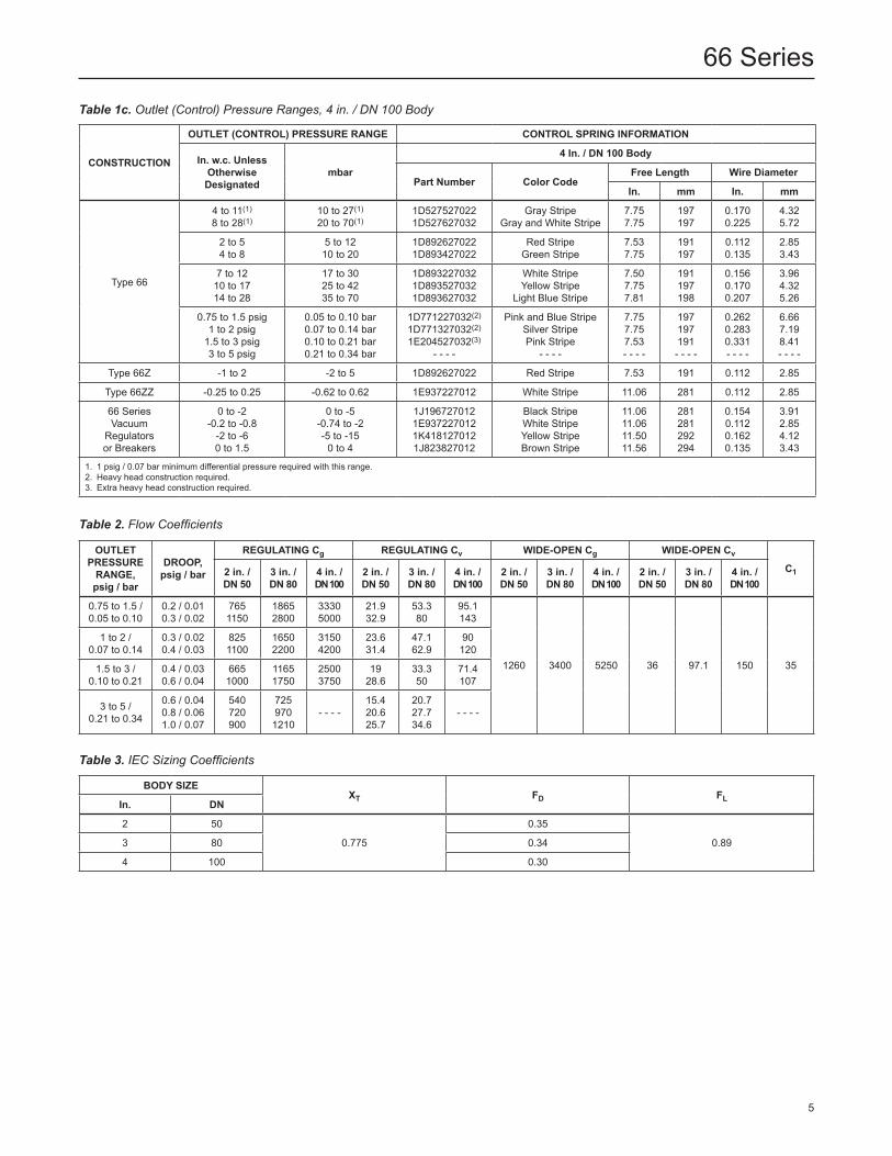
Outlet (Control) Pressure Ranges See Tables 1a to 1c
Maximum Allowable Outlet Pressures(1)
Emergency Outlet (Casing) Pressure: Type 66, 66Z or 66ZZ: 8 psig / 0.55 bar positive pressure 66 Series Vacuum Regulator: 14.7 psi or 29.9 in.
of mercury / 1.01 bar d vacuum 66 Series Vacuum Breakers: 8 psi or 16.3 in. of mercury / 0.55 bar d vacuum
Maximum Safe Pressure to Avoid Internal Parts Damage: Type 66, 66Z or 66ZZ: 1 psig / 0.07 bar d above outlet pressure setting 66 Series Vacuum Regulator: no more than 1 psig / 0.07 bar d change from spring setting
Body Sizes and End Connection Styles
COnSTRuCTIOnnOMInAlBODy SIzE
EnD COnnECTIOn STylESAnD RATInGS(1)
Standard CastIron Body
Optional Steel BodyIn. Dn
Type 66, 66Z, 66ZZ or 66
vacuum regulators or breakers
2 50 NPT or CL125 FF
NPT (all types), CL150 RF (all types), CL150 FF, CL300 RF
3, 4 80, 100 CL125 FF CL150 RF
Maximum Operating Pressure Recommended for Good Performance (66 Series Vacuum Regulators or Breakers Only): Vacuum Regulators: 10 psig or 20.4 in. of mercury / 0.69 bar d vacuum Vacuum Breakers: 6 in. w.c. or 0.4 in. of mercury / 15 mbar d vacuum
Typical Flow Capacities and Performance Curves Type 66: See Table 4, Figure 5 and “Capacity Information” section Type 66z: See Table 5, Figure 6 and “Capacity Information” section 66 Series Vacuum Regulators: See Figure 7 and “Capacity Information” section Types 66zz and 66 Series Vacuum Breakers: Consult your local Sales Office
Flow and Sizing Coefficients See Tables 2 and 3
Construction Materials Body, Body Plug, and Bottom Flange Plug when used: Cast Iron (standard), Steel or 316 Stainless steel (optional) Spring Case, and Spring Case Extension when used: Steel or 304 Stainless steel (optional) Disk Plate Assembly Seating Surface when used: Nitrile (NBR), Fluorocarbon (FKM) or Ethylenepropylene (EPDM) Diaphragm Case, Diaphragm Plates, Bottom Flange, Spring(s), and Bolting: Plated steel Diaphragm Spacer: Zinc-plated steel or 316 Stainless steel (optional) Diaphragms, and Valve Plug O-ring and Spring Case Gasket when used: Nitrile (NBR) (standard), Fluorocarbon (FKM) (high- temperature), Ethylenepropylene (EPDM) or PTFE O-ring and diaphragm protectors Bottom Flange and Stem Gaskets: Composition Diaphragm Case and Closing Cap Gaskets: Neoprene (CR) Pitot Tube when used: Copper (standard) or 304 Stainless steel Sealing Washer: Carbon steel or 316 Stainless steel Standard Type y602-10 Vent Assembly: Zinc/ Stainless steel
- continued -
2
66 Series
Specifications (continued)
Construction Materials (continued) Snap Ring: Bronze Closing Cap, and Type 66 or 66z Adjusting Screw and Spring Seats: Zinc Flapper Valve, and Type 66zz or 66 Series Vacuum Regulator or Breaker Adjusting Screw, Spring Retainer and Spring Case Coupling: Brass Orifice, Metal Seat Parts: Brass (standard) or 316 Stainless steel
nACE Construction Body: Steel upper and lower Diaphragm Case, Sealing Diaphragm Plate, Adjusting Screw and Closing Cap: Steel Disk Retainer, Disk nut, Orifice and Miscellaneous Trim Parts: 316 Stainless steel Diaphragm, O-ring and Common Parts: PTFE, Nitrile (NBR), Ethylenepropylene (EPDM) or Fluorocarbon (FKM)
Elastomer Temperature Capabilities(1)
nitrile (nBR) (Standard): -40 to 180°F / -40 to 82°C Fluorocarbon (FKM): 0 to 350°F / -18 to 177°C Ethylenepropylene (EPDM): -40 to 275°F / -40 to 135°C
Pressure Setting Adjustment Adjusting Screw
Pressure Registration Type 66, 66z or 66zz: Cast Iron Body: Internal (standard) or external Steel Body: External (standard) or internal 66 Series Vacuum Regulators or Breakers: External Control line when used: 3/4 NPT (standard) Bottom Flange line when used: 1/4 NPT standard with removable plug Spring Case Vent: 3/4 NPT standard with removable Type Y602-10 vent assembly
Approximate Weights 2 in. / Dn 50 Body: NPT Ends: 50 lbs / 22.7 kg Flanged Ends: 55 lbs / 25.0 kg 3 in. / Dn 80 Body: 100 lbs / 45.4 kg 4 in. / Dn 100 Body: 155 lbs / 70.3 kg
Options • Special springs, diaphragm plates, and other internal parts required for higher Type 66 outlet pressure ranges than shown in Table 1. • Control line connection for cast iron Type 66, 66Z or 66ZZ. • Tapped and plugged bottom flange for cast iron or steel Type 66, 66Z or 66ZZ. • Adjustable travel stops for 2 in. / DN 50 and 4 in. / DN 100 cast iron Type 66. • All-metal seats
• Severe Service Capability—Fluorocarbon (FKM), Ethylenepropylene (EPDM) and Polytetrafluoroethylene (PTFE) O-rings and stainless steel metal trim parts are available for high temperatures and/or corrosive flowing media. Optional all-metal seats eliminate O-ring seat erosion problems with coke gas or other corrosive applications. Metal valve plug also has knife-edged guides on the valve plug skirts to help prevent particle accumulation with dirty service.
• Positive Guiding—Valve plug coupling on 66 Series vacuum regulators and breakers prevent incorrect seating due to cocking or improper guiding of valve plug assembly. • Sour Gas Service Capability—Optional materials are available for applications handling sour gases. These constructions comply with the recommendations of NACE International Standards MR0175 and MR0103.
1. The pressure/temperature limits in this Bulletin and any applicable standard or code limitation for valve should not be exceeded.
3
66 Series
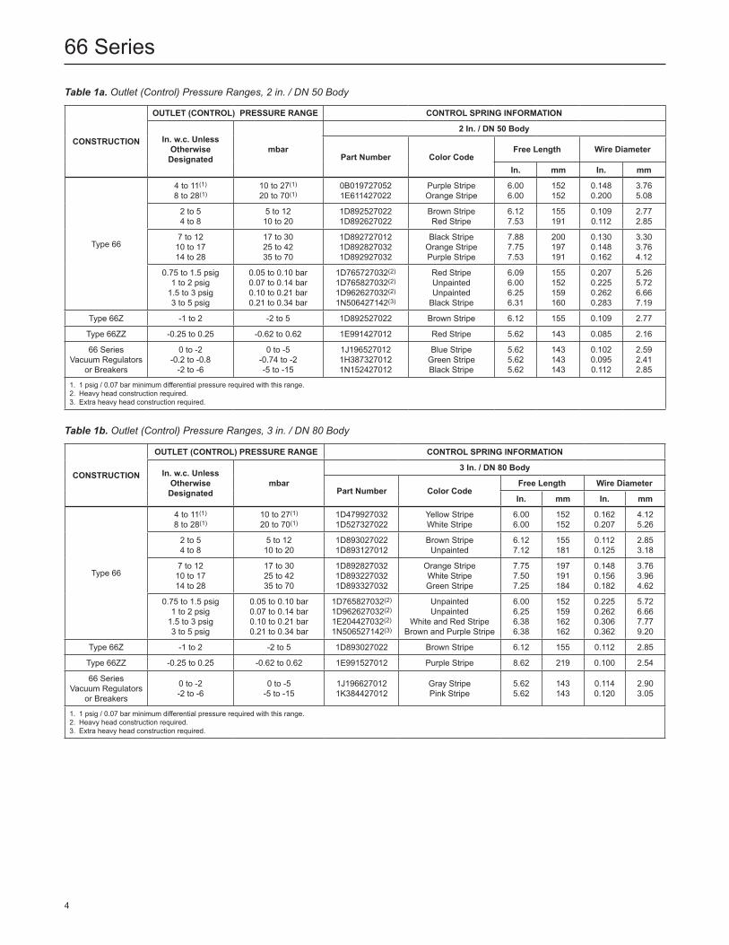
Table 1a. Outlet (Control) Pressure Ranges, 2 in. / DN 50 Body
COnSTRuCTIOn
OuTlET (COnTROl) PRESSuRE RAnGE COnTROl SPRInG InFORMATIOn
In. w.c. unlessOtherwise Designated
mbar
2 In. / Dn 50 Body
Part number Color CodeFree length Wire Diameter
In. mm In. mm
Type 66
4 to 11(1)
8 to 28(1)10 to 27(1)
20 to 70(1)0B0197270521E611427022
Purple StripeOrange Stripe
6.006.00
152152
0.1480.200
3.765.08
2 to 54 to 8
5 to 1210 to 20
1D8925270221D892627022
Brown StripeRed Stripe
6.127.53
155191
0.1090.112
2.772.85
7 to 1210 to 1714 to 28
17 to 3025 to 4235 to 70
1D8927270121D8928270321D892927032
Black StripeOrange StripePurple Stripe
7.887.757.53
200197191
0.1300.1480.162
3.303.764.12
0.75 to 1.5 psig1 to 2 psig
1.5 to 3 psig3 to 5 psig
0.05 to 0.10 bar0.07 to 0.14 bar0.10 to 0.21 bar0.21 to 0.34 bar
1D765727032(2)
1D765827032(2)
1D962627032(2)
1N506427142(3)
Red StripeUnpaintedUnpainted
Black Stripe
6.096.006.256.31
155152159160
0.2070.2250.2620.283
5.265.726.667.19
Type 66Z -1 to 2 -2 to 5 1D892527022 Brown Stripe 6.12 155 0.109 2.77
Type 66ZZ -0.25 to 0.25 -0.62 to 0.62 1E991427012 Red Stripe 5.62 143 0.085 2.16
66 SeriesVacuum Regulators
or Breakers
0 to -2-0.2 to -0.8
-2 to -6
0 to -5-0.74 to -2-5 to -15
1J1965270121H3873270121N152427012
Blue StripeGreen StripeBlack Stripe
5.625.625.62
143143143
0.1020.0950.112
2.592.412.85
1. 1 psig / 0.07 bar minimum differential pressure required with this range.2. Heavy head construction required.3. Extra heavy head construction required.
COnSTRuCTIOn
OuTlET (COnTROl) PRESSuRE RAnGE COnTROl SPRInG InFORMATIOn
In. w.c. unlessOtherwise Designated
mbar
3 In. / Dn 80 Body
Part number Color CodeFree length Wire Diameter
In. mm In. mm
Type 66
4 to 11(1)
8 to 28(1)10 to 27(1)
20 to 70(1)1D4799270321D527327022
Yellow StripeWhite Stripe
6.006.00
152152
0.1620.207
4.125.26
2 to 54 to 8
5 to 1210 to 20
1D8930270221D893127012
Brown StripeUnpainted
6.127.12
155181
0.1120.125
2.853.18
7 to 1210 to 1714 to 28
17 to 3025 to 4235 to 70
1D8928270321D8932270321D893327032
Orange StripeWhite StripeGreen Stripe
7.757.507.25
197191184
0.1480.1560.182
3.763.964.62
0.75 to 1.5 psig1 to 2 psig
1.5 to 3 psig3 to 5 psig
0.05 to 0.10 bar0.07 to 0.14 bar0.10 to 0.21 bar0.21 to 0.34 bar
1D765827032(2)
1D962627032(2)
1E204427032(2)
1N506527142(3)
UnpaintedUnpainted
White and Red StripeBrown and Purple Stripe
6.006.256.386.38
152159162162
0.2250.2620.3060.362
5.726.667.779.20
Type 66Z -1 to 2 -2 to 5 1D893027022 Brown Stripe 6.12 155 0.112 2.85
Type 66ZZ -0.25 to 0.25 -0.62 to 0.62 1E991527012 Purple Stripe 8.62 219 0.100 2.54
66 SeriesVacuum Regulators
or Breakers
0 to -2-2 to -6
0 to -5-5 to -15
1J1966270121K384427012
Gray StripePink Stripe
5.625.62
143143
0.1140.120
2.903.05
1. 1 psig / 0.07 bar minimum differential pressure required with this range.2. Heavy head construction required.3. Extra heavy head construction required.
Table 1b. Outlet (Control) Pressure Ranges, 3 in. / DN 80 Body
4
66 Series
COnSTRuCTIOn
OuTlET (COnTROl) PRESSuRE RAnGE COnTROl SPRInG InFORMATIOn
In. w.c. unlessOtherwise Designated
mbar
4 In. / Dn 100 Body
Part number Color CodeFree length Wire Diameter
In. mm In. mm
Type 66
4 to 11(1)
8 to 28(1)10 to 27(1)
20 to 70(1)1D5275270221D527627032
Gray StripeGray and White Stripe
7.75 7.75
197197
0.1700.225
4.325.72
2 to 54 to 8
5 to 1210 to 20
1D8926270221D893427022
Red StripeGreen Stripe
7.53 7.75
191197
0.1120.135
2.853.43
7 to 1210 to 1714 to 28
17 to 3025 to 4235 to 70
1D8932270321D8935270321D893627032
White StripeYellow Stripe
Light Blue Stripe
7.50 7.75 7.81
191197198
0.1560.1700.207
3.964.325.26
0.75 to 1.5 psig1 to 2 psig
1.5 to 3 psig3 to 5 psig
0.05 to 0.10 bar0.07 to 0.14 bar0.10 to 0.21 bar0.21 to 0.34 bar
1D771227032(2)
1D771327032(2)
1E204527032(3)
- - - -
Pink and Blue StripeSilver StripePink Stripe
- - - -
7.75 7.75 7.53 - - - -
197197191- - - -
0.2620.2830.331- - - -
6.667.198.41- - - -
Type 66Z -1 to 2 -2 to 5 1D892627022 Red Stripe 7.53 191 0.112 2.85
Type 66ZZ -0.25 to 0.25 -0.62 to 0.62 1E937227012 White Stripe 11.06 281 0.112 2.85
66 SeriesVacuum
Regulatorsor Breakers
0 to -2-0.2 to -0.8
-2 to -60 to 1.5
0 to -5-0.74 to -2-5 to -15
0 to 4
1J1967270121E9372270121K4181270121J823827012
Black StripeWhite StripeYellow StripeBrown Stripe
11.06 11.06 11.50 11.56
281281292294
0.1540.1120.1620.135
3.912.854.123.43
1. 1 psig / 0.07 bar minimum differential pressure required with this range.2. Heavy head construction required.3. Extra heavy head construction required.
Table 1c. Outlet (Control) Pressure Ranges, 4 in. / DN 100 Body
Table 2. Flow Coefficients
OuTlET PRESSuRERAnGE, psig / bar
DROOP,psig / bar
REGulATInG Cg REGulATInG Cv WIDE-OPEn Cg WIDE-OPEn Cv
C12 in. / Dn 50
3 in. / Dn 80
4 in. /Dn 100
2 in. /Dn 50
3 in. / Dn 80
4 in. /Dn 100
2 in. /Dn 50
3 in. /Dn 80
4 in. /Dn 100
2 in. /Dn 50
3 in. / Dn 80
4 in. /Dn 100
0.75 to 1.5 /0.05 to 0.10
0.2 / 0.010.3 / 0.02
7651150
18652800
33305000
21.932.9
53.380
95.1143
1260 3400 5250 36 97.1 150 35
1 to 2 /0.07 to 0.14
0.3 / 0.020.4 / 0.03
8251100
16502200
31504200
23.631.4
47.162.9
90120
1.5 to 3 /0.10 to 0.21
0.4 / 0.030.6 / 0.04
6651000
11651750
25003750
1928.6
33.350
71.4107
3 to 5 /0.21 to 0.34
0.6 / 0.040.8 / 0.061.0 / 0.07
540720900
7259701210
- - - -15.420.625.7
20.727.734.6
- - - -
BODy SIzEXT FD FlIn. Dn
2 50
0.775
0.35
0.893 80 0.34
4 100 0.30
Table 3. IEC Sizing Coefficients
5
66 Series
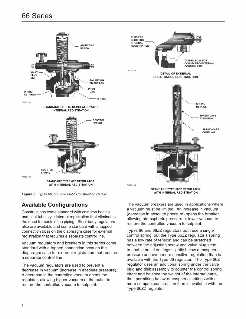
Available ConfigurationsConstructions come standard with cast iron bodies and pitot tube style internal registration that eliminates the need for control line piping. Steel-body regulators also are available and come standard with a tapped connection boss on the diaphragm case for external registration that requires a separate control line.
Vacuum regulators and breakers in this series come standard with a tapped connection boss on the diaphragm case for external registration that requires a separate control line.
The vacuum regulators are used to prevent a decrease in vacuum (increase in absolute pressure). A decrease in the controlled vacuum opens the regulator, allowing higher vacuum at the outlet to restore the controlled vacuum to setpoint.
Figure 2. Types 66, 66Z and 66ZZ Construction DetailsSTAnDARD TyPE 66zz REGulATOR WITh InTERnAl REGISTRATIOn
W0041_1*/IL
SPRInGRETAInER
SPRInG CASEExTEnSIOn
SPRInG CASECOuPlInG
STAnDARD TyPE 66z REGulATOR WITh InTERnAl REGISTRATIOn
W0036_1*/IL
COnTROlSPRInG
COunTERSPRInG
DETAIl OF ExTERnAlREGISTRATIOn COnSTRuCTIOn
W0037_1*/IL
PluG FORBlOCKInG InTERnAlREGISTRATIOn
TAPPED BOSS FORCOnnECTInG ExTERnAlCOnTROl lInE
STAnDARD TyPE 66 REGulATOR WITh InTERnAl REGISTRATIOn
W0037_1*/IL
ADjuSTInG SCREW
VAlVEPluGSKIRT
BAlAnCInGDIAPhRAGM
O-RInGRETAInER
PITOTTuBE
O-RInG
The vacuum breakers are used in applications where a vacuum must be limited. An increase in vacuum (decrease in absolute pressure) opens the breaker, allowing atmospheric pressure or lower vacuum to restore the controlled vacuum to setpoint.
Types 66 and 66ZZ regulators both use a single control spring, but the Type 66ZZ regulator’s spring has a low rate of tension and can be stretched between the adjusting screw and valve plug stem to enable outlet settings slightly below atmospheric pressure and even more sensitive regulation than is available with the Type 66 regulator. The Type 66Z regulator uses an additional spring under the valve plug and disk assembly to counter the control spring effect and balance the weight of the internal parts, thus permitting below-atmospheric settings with a more compact construction than is available with the Type 66ZZ regulator.
6
66 Series
InlET PRESSuRE
OuTlET PRESSuREATMOSPhERIC PRESSuRE
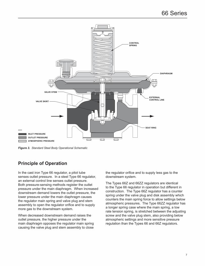
Figure 3. Standard Steel Body Operational Schematic
A6550
Principle of Operation
In the cast iron Type 66 regulator, a pitot tube senses outlet pressure. In a steel Type 66 regulator, an external control line senses outlet pressure. Both pressure-sensing methods register the outlet pressure under the main diaphragm. When increased downstream demand lowers the outlet pressure, the lower pressure under the main diaphragm causes the regulator main spring and valve plug and stem assembly to open the regulator orifice and to supply more gas to the downstream system.
When decreased downstream demand raises the outlet pressure, the higher pressure under the main diaphragm opposes the regulator main spring causing the valve plug and stem assembly to close
the regulator orifice and to supply less gas to the downstream system.
The Types 66Z and 66ZZ regulators are identical to the Type 66 regulator in operation but different in construction. The Type 66Z regulator has a counter spring under the valve plug and disk assembly which counters the main spring force to allow settings below atmospheric pressures. The Type 66ZZ regulator has a longer spring case where the main spring, a low rate tension spring, is stretched between the adjusting screw and the valve plug stem, also providing below atmospheric settings and more sensitive pressure regulation than the Types 66 and 66Z regulators.
COnTROl SPRInG
DIAPhRAGM
VAlVE STEM
VAlVE SKIRT
ExTERnAl COnTROl lInE
SEAT RInG
7
66 Series
InstallationA 66 Series regulator or breaker should be installed horizontally with the diaphragm casings vertical above the body. Other orientations will change the setpoint and outlet pressure range due to the weight of the internal parts. Typical installations are shown in Figures 8 through 10.
To obtain the maximum flow capacities in some instances, outlet piping will have to be swaged up above the body sizes.
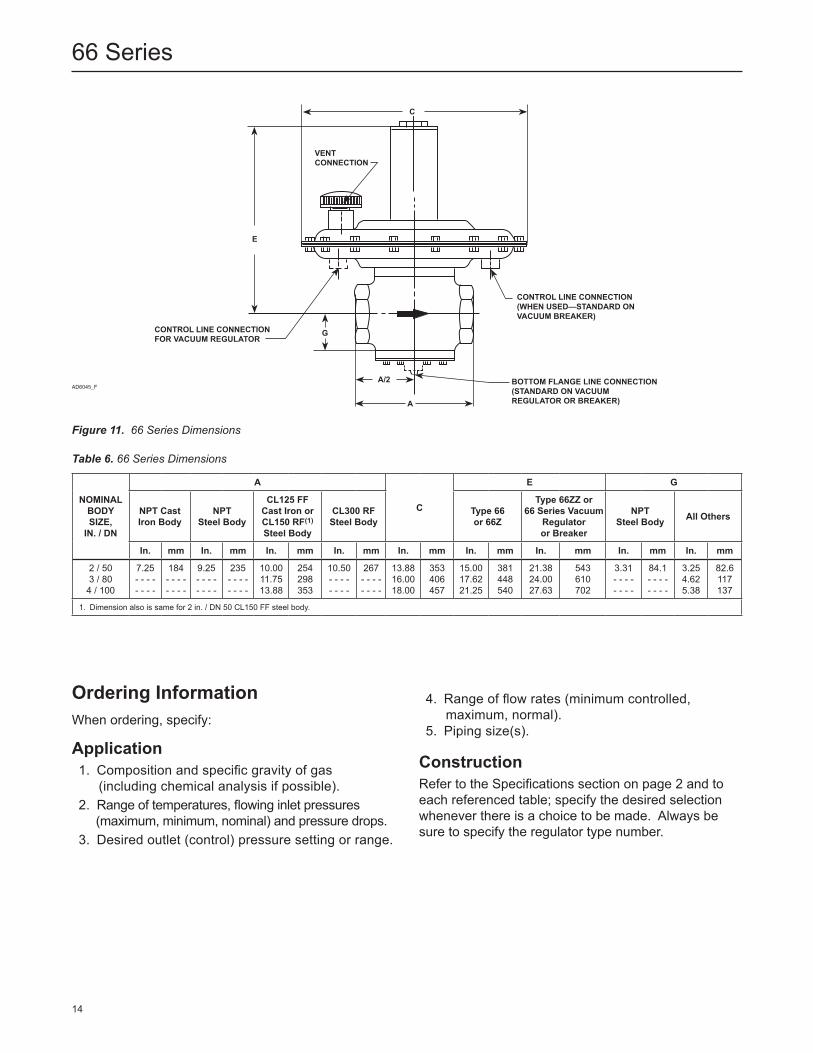
Connection locations and dimensions are both shown in Figure 11.
Overpressure Protection
66 Series pressure-reducing regulators, vacuum regulators and vacuum breakers have different inlet and outlet pressure ratings. Complete downstream overpressure protection is needed whenever the maximum allowable inlet pressure can exceed the outlet pressure rating and upstream protection for a 66 Series vacuum regulator additionally is needed if there is any chance of a vacuum greater than 8 psi or 16.3 in. of mercury / 0.55 bar d occurring at the inlet of this kind of regulator.
Overpressuring any portion of a regulator, breaker, or associated equipment may cause leakage, part damage, or personal injury due to bursting of pressure-containing parts, explosion of accumulated gas, or implosion due to excessive vacuum. Regulator or breaker operation within ratings does not preclude the possibility of damage from external sources or from debris in the pipeline. A regulator or breaker should be inspected for damage periodically and after any overpressure condition.
Capacity Information
Table 4 gives Type 66 and Table 5 gives Type 66Z natural gas regulating capacities at selected inlet pressures and outlet pressure settings. Flows are in SCFH at 60°F and 14.7 psia (and in Nm³/h at 0°C and 1.01325 bar) of 0.6 specific gravity natural gas. To determine equivalent capacities for air, propane, butane or nitrogen, multiply Table 4 or 5 capacity by the following appropriate conversion factor: 0.775 for air, 0.628 for propane, 0.548 for butane or 0.789 for nitrogen. For gases of other specific gravities, multiply the given capacity by 0.775 and divide by the square root of the appropriate specific gravity. Then,
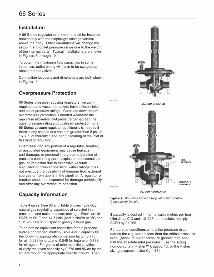
Figure 4. 66 Series Vacuum Regulator and Breaker Construction Details
VACuuM BREAKER
VACuuM REGulATOR
W3127_1/IL
W0032_1*/IL
DISKRETAInER
DISK PlATEASSEMBly
if capacity is desired in normal cubic meters per hour (Nm3/h) at 0°C and 1.01325 bar absolute, multiply SCFH by 0.0268.
For service conditions where the pressure drop across the regulator is less than the critical pressure drop, (absolute outlet pressure greater than one-half the absolute inlet pressure), use the sizing nomographs in Fisher™ Catalog 10, or the Fisher sizing program. (Use C1 = 35)
8
66 Series
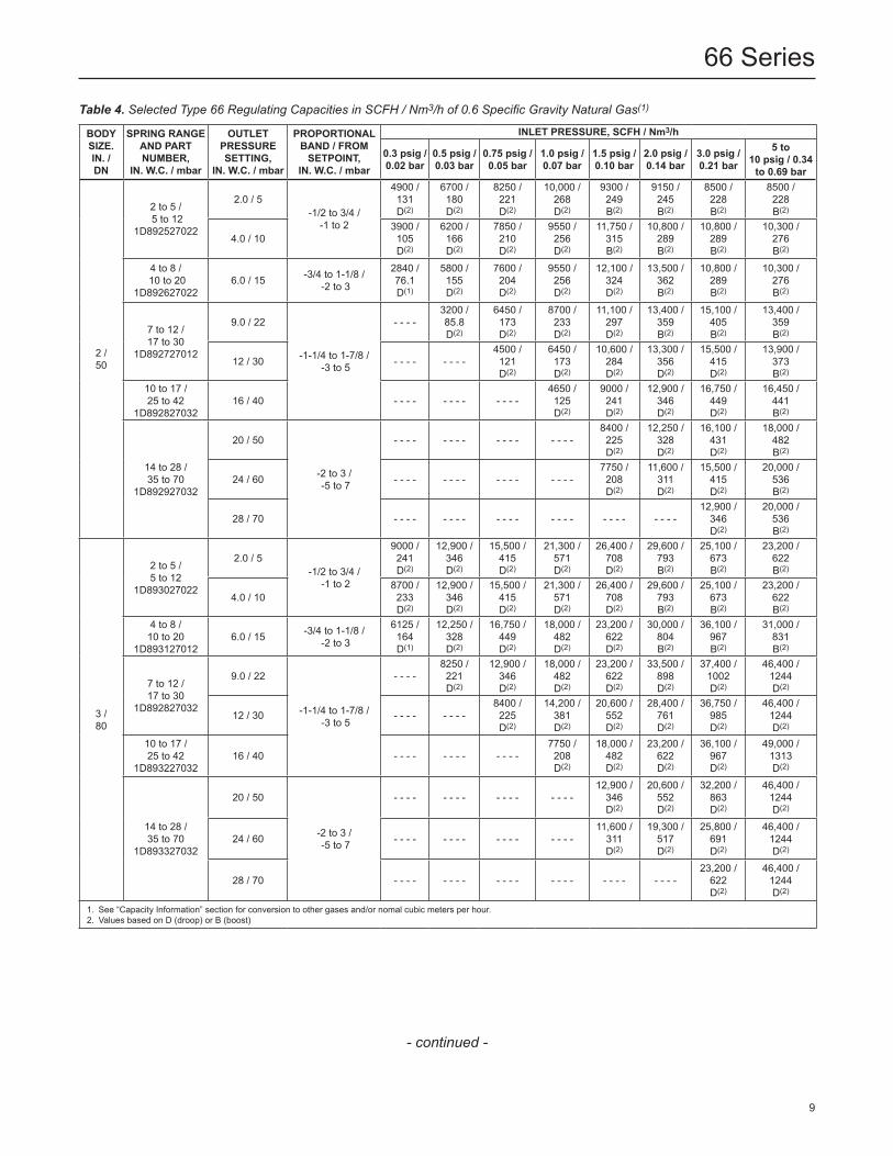
Table 4. Selected Type 66 Regulating Capacities in SCFH / Nm3/h of 0.6 Specific Gravity Natural Gas(1)
BODy SIzE.In. /Dn
SPRInG RAnGEAnD PARTnuMBER,
In. W.C. / mbar
OuTlETPRESSuRESETTInG,
In. W.C. / mbar
PROPORTIOnAl BAnD / FROM SETPOInT,
In. W.C. / mbar
InlET PRESSuRE, SCFh / nm3/h
0.3 psig / 0.02 bar
0.5 psig / 0.03 bar
0.75 psig / 0.05 bar
1.0 psig / 0.07 bar
1.5 psig / 0.10 bar
2.0 psig / 0.14 bar
3.0 psig / 0.21 bar
5 to 10 psig / 0.34 to 0.69 bar
2 /50
2 to 5 / 5 to 12
1D892527022
2.0 / 5-1/2 to 3/4 /
-1 to 2
4900 /131D(2)
6700 /180D(2)
8250 /221D(2)
10,000 /268D(2)
9300 /249 B(2)
9150 / 245B(2)
8500 / 228B(2)
8500 / 228B(2)
4.0 / 103900 /105D(2)
6200 /166D(2)
7850 /210D(2)
9550 /256D(2)
11,750 /315B(2)
10,800 / 289B(2)
10,800 / 289B(2)
10,300 / 276B(2)
4 to 8 / 10 to 20
1D8926270226.0 / 15 -3/4 to 1-1/8 /
-2 to 3
2840 /76.1D(1)
5800 /155D(2)
7600 /204D(2)
9550 /256D(2)
12,100 /324D(2)
13,500 / 362B(2)
10,800 / 289B(2)
10,300 / 276B(2)
7 to 12 /17 to 30
1D892727012
9.0 / 22
-1-1/4 to 1-7/8 / -3 to 5
- - - -3200 /85.8D(2)
6450 /173D(2)
8700 /233D(2)
11,100 /297D(2)
13,400 / 359B(2)
15,100 / 405B(2)
13,400 / 359B(2)
12 / 30 - - - - - - - -4500 /121D(2)
6450 /173D(2)
10,600 /284D(2)
13,300 / 356D(2)
15,500 / 415D(2)
13,900 / 373B(2)
10 to 17 /25 to 42
1D89282703216 / 40 - - - - - - - - - - - -
4650 / 125D(2)
9000 /241D(2)
12,900 / 346D(2)
16,750 / 449D(2)
16,450 / 441B(2)
14 to 28 /35 to 70
1D892927032
20 / 50
-2 to 3 / -5 to 7
- - - - - - - - - - - - - - - -8400 / 225D(2)
12,250 / 328D(2)
16,100 / 431D(2)
18,000 / 482B(2)
24 / 60 - - - - - - - - - - - - - - - -7750 / 208D(2)
11,600 / 311D(2)
15,500 / 415D(2)
20,000 / 536B(2)
28 / 70 - - - - - - - - - - - - - - - - - - - - - - - -12,900 /
346D(2)
20,000 / 536B(2)
3 /80
2 to 5 /5 to 12
1D893027022
2.0 / 5-1/2 to 3/4 /
-1 to 2
9000 /241D(2)
12,900 /346D(2)
15,500 /415D(2)
21,300 /571D(2)
26,400 / 708D(2)
29,600 / 793B(2)
25,100 / 673B(2)
23,200 / 622B(2)
4.0 / 108700 /233D(2)
12,900 /346D(2)
15,500 /415D(2)
21,300 /571D(2)
26,400 / 708D(2)
29,600 / 793B(2)
25,100 / 673B(2)
23,200 / 622B(2)
4 to 8 /10 to 20
1D8931270126.0 / 15 -3/4 to 1-1/8 /
-2 to 3
6125 /164D(1)
12,250 /328D(2)
16,750 /449D(2)
18,000 /482D(2)
23,200 / 622D(2)
30,000 / 804B(2)
36,100 / 967B(2)
31,000 / 831B(2)
7 to 12 /17 to 30
1D892827032
9.0 / 22
-1-1/4 to 1-7/8 / -3 to 5
- - - -8250 /221D(2)
12,900 /346D(2)
18,000 /482 D(2)
23,200 / 622D(2)
33,500 / 898D(2)
37,400 / 1002D(2)
46,400 / 1244D(2)
12 / 30 - - - - - - - -8400 /225D(2)
14,200 /381D(2)
20,600 / 552D(2)
28,400 / 761D(2)
36,750 / 985D(2)
46,400 / 1244D(2)
10 to 17 /25 to 42
1D89322703216 / 40 - - - - - - - - - - - -
7750 /208D(2)
18,000 / 482D(2)
23,200 / 622D(2)
36,100 / 967D(2)
49,000 / 1313D(2)
14 to 28 /35 to 70
1D893327032
20 / 50
-2 to 3 / -5 to 7
- - - - - - - - - - - - - - - -12,900 /
346D(2)
20,600 / 552D(2)
32,200 / 863D(2)
46,400 / 1244D(2)
24 / 60 - - - - - - - - - - - - - - - -11,600 /
311D(2)
19,300 / 517D(2)
25,800 / 691D(2)
46,400 / 1244D(2)
28 / 70 - - - - - - - - - - - - - - - - - - - - - - - -23,200 /
622D(2)
46,400 / 1244D(2)
1. See “Capacity Information” section for conversion to other gases and/or nomal cubic meters per hour. 2. Values based on D (droop) or B (boost)
- continued -
9
66 Series
Table 4. Selected Type 66 Regulating Capacities in SCFH / Nm3/h of 0.6 Specific Gravity Natural Gas(1) (continued)
Table 5. Selected Type 66Z Regulating Capacities in SCFH / Nm3/h of 0.6 Specific Gravity Natural Gas(1)
InlETPRESSuRE
2 In. W.C. / 5 mbar OuTlET PRESSuRE SETTInG
2 in. / Dn 50 Body 3 in. / Dn 80 Body 4 in. / Dn 100 Body
In. w.c. mbar SCFh nm3/h SCFh nm3/h SCFh nm3/h
34814
7102035
1930232049006700
51,762,2131180
387051609000
12,900
104138241346
77509000
15,50023,200
208241415622
1 psig2 psig3 psig5 psig
0.07 bar0.14 bar0.21 bar0.34 bar
10 000915085008500
268245228228
21,30026,40033,50036,100
571708898967
36,10036,10050,00050,000
96796713401340
1. See “Capacity Information” section for conversion to equivalent capacities of other gases and/or normal cubic meters per hour.
BODy SIzE,In. /Dn
SPRInG RAnGEAnD PARTnuMBER,
In. W.C. / mbar
OuTlETPRESSuRESETTInG,
In. W.C. / mbar
PROPORTIOnAl BAnD / FROM SETPOInT,
In. W.C. / mbar
InlET PRESSuRE, SCFh / nm3/h
0.3 psig / 0.02 bar
0.5 psig / 0.03 bar
0.75 psig / 0.05 bar
1.0 psig / 0.07 bar
1.5 psig / 0.10 bar
2.0 psig / 0.14 bar
3.0 psig / 0.21 bar
5 to 10 psig / 0,34 to 0.69 bar
4 / 100
2 to 5 / 5 to 12
1D892627022
2.0 / 5–1/2 to 3/4 /
–1 to 2
15,500 / 415D(2)
23,200 / 622D(2)
28,400 / 761B(2)
36,100 / 967B(2)
36,100 / 967B(2)
36,100 / 967B(2)
36,100 / 967B(2)
36,100 / 967B(2)
4.0 / 1015,500 /
415D(2)
23,200 / 622D(2)
28,400 / 761B(2)
36,100 / 967B(2)
36,100 / 967B(2)
36,100 / 967B(2)
36,100 / 967B(2)
36,100 / 967B(2)
4 to 8 / 10 to 20
1D8934270226.0 / 15 –3/4 to 1-1/8 /
–2 to 3
11,600 / 311D(2)
18,000 / 482D(2)
24,500 / 657D(2)
34,800 / 933D(2)
38,700 / 1037B(2)
43,800 / 1174B(2)
43,000 / 1152B(2)
43,800 / 1174B(2)
7 to 12 / 17 to 30
1D893227032
9.0 / 22
–1-1/4 to 1-7/8 / –3 to 5
- - - -12,900 /
346D(2)
20,600 / 552D(2)
33,500 / 898D(2)
41,300 / 1107D(2)
51,500 / 1380B(2)
51,500 / 1380B(2)
51,500 / 1380B(2)
12 / 30 - - - - - - - -12,900 /
346D(2)
22,600 / 606D(2)
38,700 / 1037D(2)
51,500 / 1380D(2)
58,000 / 1554D(2)
56,700 / 1520D(2)
10 to 17 / 25 to 42
1D89352703216 / 40 - - - - - - - - - - - -
20,600 / 552D(2)
36,100 / 967D(2)
51,500 / 1380D(2)
64,500 / 1729D(2)
61,800 / 1656D(2)
14 to 28 / 35 to 70
1D893627032
20 / 50
–2 to 3 / –5 to 7
- - - - - - - - - - - - - - - -27,000 /
724D(2)
46,400 / 1244D(2)
61,800 / 1656D(2)
71,000 / 1903D(2)
24 / 60 - - - - - - - - - - - - - - - - - - - -41,300 /
1107D(2)
61,800 / 1656D(2)
77,500 /2077D(2)
28 / 70 - - - - - - - - - - - - - - - - - - - - - - - -58,000 /
1554D(2)
77,500 /2077D(2)
1. See “Capacity Information” section for conversion to other gases and/or nomal cubic meters per hour. 2. Values based on D (droop) or B (boost)
10
66 Series
A2567/IL
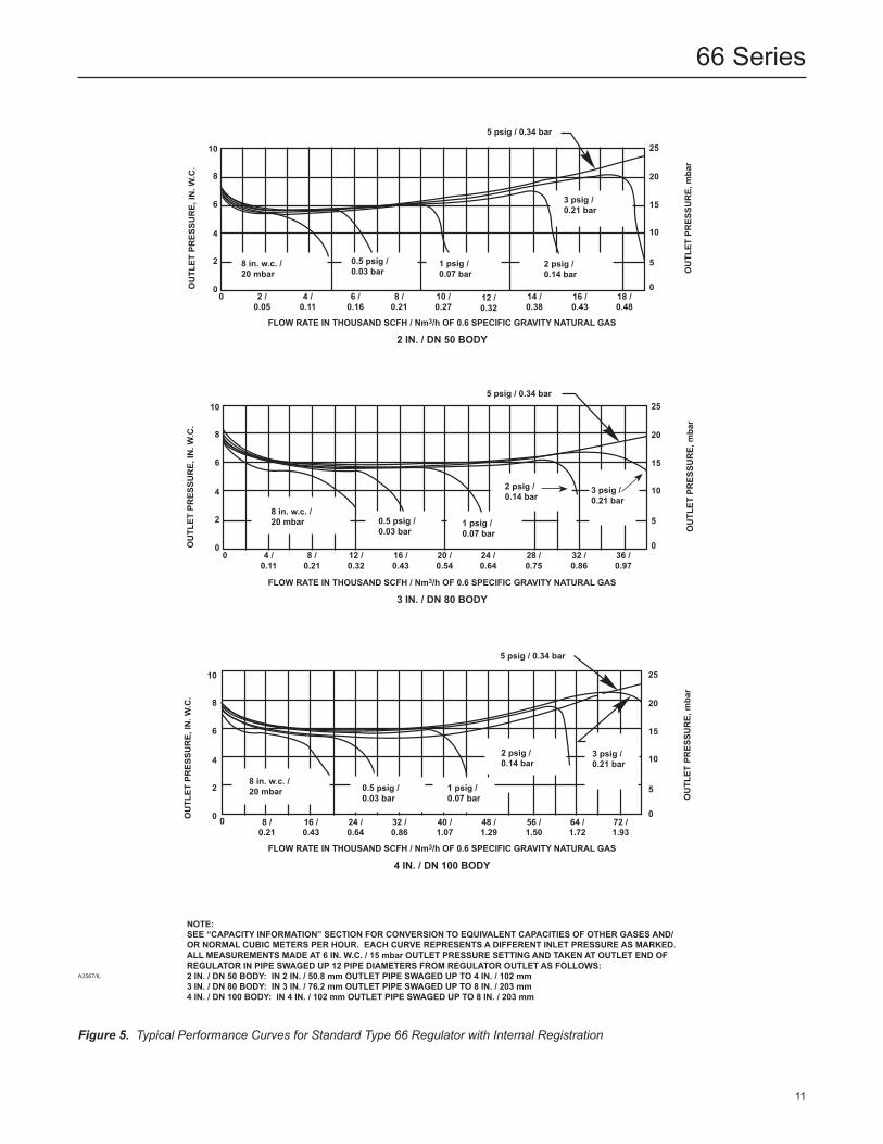
Figure 5. Typical Performance Curves for Standard Type 66 Regulator with Internal Registration
nOTE:SEE “CAPACITy InFORMATIOn” SECTIOn FOR COnVERSIOn TO EQuIVAlEnT CAPACITIES OF OThER GASES AnD/OR nORMAl CuBIC METERS PER hOuR. EACh CuRVE REPRESEnTS A DIFFEREnT InlET PRESSuRE AS MARKED. All MEASuREMEnTS MADE AT 6 In. W.C. / 15 mbar OuTlET PRESSuRE SETTInG AnD TAKEn AT OuTlET EnD OF REGulATOR In PIPE SWAGED uP 12 PIPE DIAMETERS FROM REGulATOR OuTlET AS FOllOWS:2 In. / Dn 50 BODy: In 2 In. / 50.8 mm OuTlET PIPE SWAGED uP TO 4 In. / 102 mm3 In. / Dn 80 BODy: In 3 In. / 76.2 mm OuTlET PIPE SWAGED uP TO 8 In. / 203 mm4 In. / Dn 100 BODy: In 4 In. / 102 mm OuTlET PIPE SWAGED uP TO 8 In. / 203 mm
FlOW RATE In ThOuSAnD SCFh / nm3/h OF 0.6 SPECIFIC GRAVITy nATuRAl GAS
2 In. / Dn 50 BODy
OuTl
ET PRES
SuRE, In
. W.C.
OuTl
ET PRES
SuRE, mbar
5 psig / 0.34 bar
3 psig /0.21 bar
2 psig / 0.14 bar
1 psig / 0.07 bar
25
20
15
10
5
012 /0.32
14 /0.38
16 /0.43
18 /0.48
10 /0.27
4 /0.11
6 /0.16
8 /0.21
0.5 psig / 0.03 bar
8 in. w.c. /20 mbar
0
10
8
4
6
0
2
2 / 0.05
FlOW RATE In ThOuSAnD SCFh / nm3/h OF 0.6 SPECIFIC GRAVITy nATuRAl GAS
4 In. / Dn 100 BODy
OuTl
ET PRES
SuRE, mbar
25
20
15
10
5
048 /1.29
56 /1.50
64 /1.72
72 /1.93
40 /1.07
10
8
4
6
0
2
OuTl
ET PRES
SuRE, In
. W.C.
5 psig / 0.34 bar
3 psig /0.21 bar
2 psig /0.14 bar
1 psig /0.07 bar
0.5 psig /0.03 bar
8 in. w.c. /20 mbar
24 /0.64
32 /0.86
16 /0.43
8 /0.21
0
FlOW RATE In ThOuSAnD SCFh / nm3/h OF 0.6 SPECIFIC GRAVITy nATuRAl GAS
3 In. / Dn 80 BODy
OuTl
ET PRES
SuRE, mbar
25
20
15
10
5
024 /0.64
28 /0.75
32 /0.86
36 /0.97
10
8
4
6
0
28 in. w.c. /20 mbar
5 psig / 0.34 bar
3 psig /0.21 bar
2 psig /0.14 bar
1 psig /0.07 bar
0.5 psig /0.03 bar
OuTl
ET PRES
SuRE, In
. W.C.
12 /0.32
16 /0.43
4 /0.11
8 /0.21
0 20 /0.54
11
66 Series
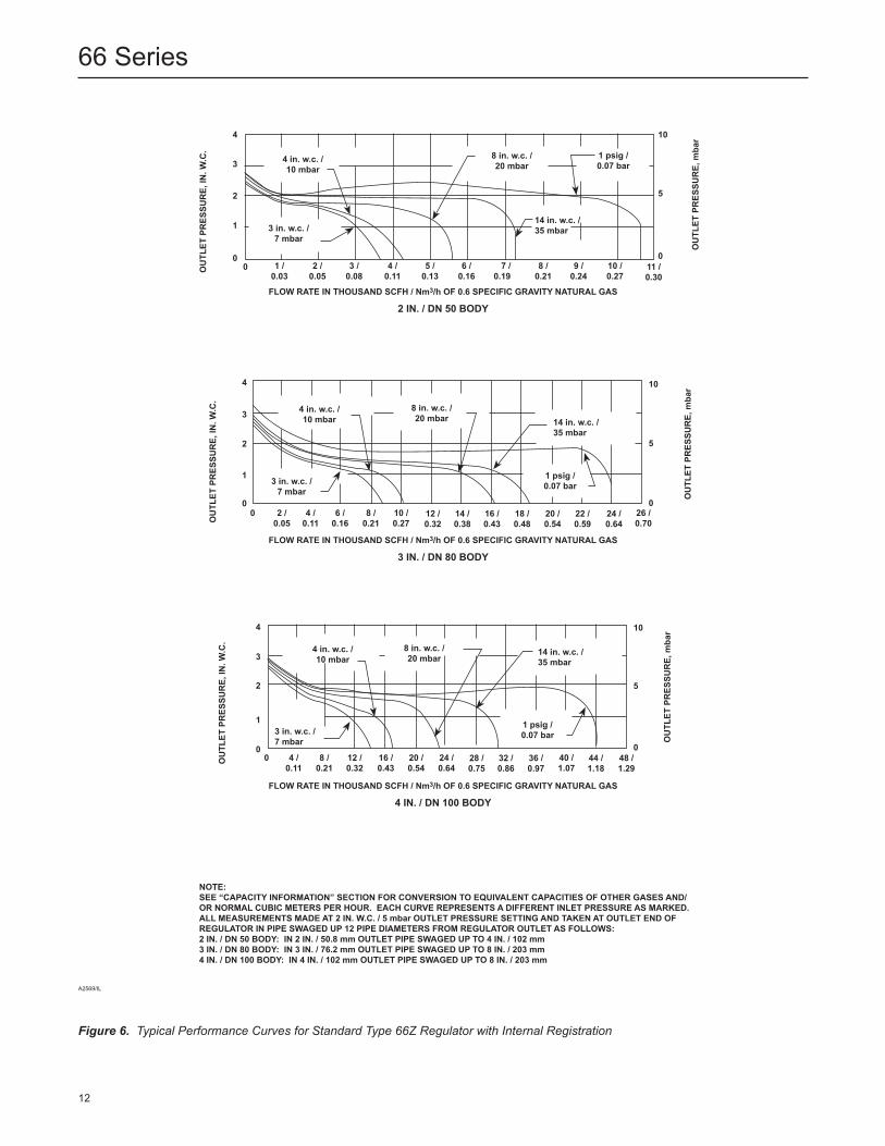
Figure 6. Typical Performance Curves for Standard Type 66Z Regulator with Internal Registration
A2569/IL
nOTE:SEE “CAPACITy InFORMATIOn” SECTIOn FOR COnVERSIOn TO EQuIVAlEnT CAPACITIES OF OThER GASES AnD/OR nORMAl CuBIC METERS PER hOuR. EACh CuRVE REPRESEnTS A DIFFEREnT InlET PRESSuRE AS MARKED. All MEASuREMEnTS MADE AT 2 In. W.C. / 5 mbar OuTlET PRESSuRE SETTInG AnD TAKEn AT OuTlET EnD OF REGulATOR In PIPE SWAGED uP 12 PIPE DIAMETERS FROM REGulATOR OuTlET AS FOllOWS:2 In. / Dn 50 BODy: In 2 In. / 50.8 mm OuTlET PIPE SWAGED uP TO 4 In. / 102 mm3 In. / Dn 80 BODy: In 3 In. / 76.2 mm OuTlET PIPE SWAGED uP TO 8 In. / 203 mm4 In. / Dn 100 BODy: In 4 In. / 102 mm OuTlET PIPE SWAGED uP TO 8 In. / 203 mm
FlOW RATE In ThOuSAnD SCFh / nm3/h OF 0.6 SPECIFIC GRAVITy nATuRAl GAS
2 In. / Dn 50 BODy
OuTl
ET PRES
SuRE, mbar
OuTl
ET PRES
SuRE, In
. W.C.
4
4 in. w.c. /10 mbar
8 in. w.c. / 20 mbar
1 psig /0.07 bar
3 in. w.c. /7 mbar
14 in. w.c. /35 mbar
8 /0.21
7 /0.19
4 /0.11
3
2
1
0
10
5
00 1 /
0.036 /0.16
5 /0.13
3 /0.08
2 /0.05
10 /0.27
9 /0.24
11 /0.30
FlOW RATE In ThOuSAnD SCFh / nm3/h OF 0.6 SPECIFIC GRAVITy nATuRAl GAS
3 In. / Dn 80 BODy
OuTl
ET PRES
SuRE, mbar
OuTl
ET PRES
SuRE, In
. W.C.
4
3
2
1
0
10
5
018 /0.48
16 /0.43
14 /0.38
12 /0.32
26 /0.70
24 /0.64
22 /0.59
20 /0.54
4 in. w.c. /10 mbar
8 in. w.c. /20 mbar
1 psig /0.07 bar
14 in. w.c. /35 mbar
3 in. w.c. /7 mbar
8 /0.21
4 /0.11
0 6 /0.16
2 /0.05
10 /0.27
FlOW RATE In ThOuSAnD SCFh / nm3/h OF 0.6 SPECIFIC GRAVITy nATuRAl GAS
4 In. / Dn 100 BODy
OuTl
ET PRES
SuRE, mbar
OuTl
ET PRES
SuRE, In
. W.C.
4
3
2
1
0
10
5
032 /0.86
28 /0.75
48 /1.29
44 /1.18
36 /0.97
4 in. w.c. / 10 mbar
8 in. w.c. /20 mbar
1 psig /0.07 bar
14 in. w.c. /35 mbar
3 in. w.c. /7 mbar
16 /0.43
12 /0.32
24 /0.64
20 /0.54
8 /0.21
4 /0.11
0 40 /1.07
12
66 Series
BJ9126_A
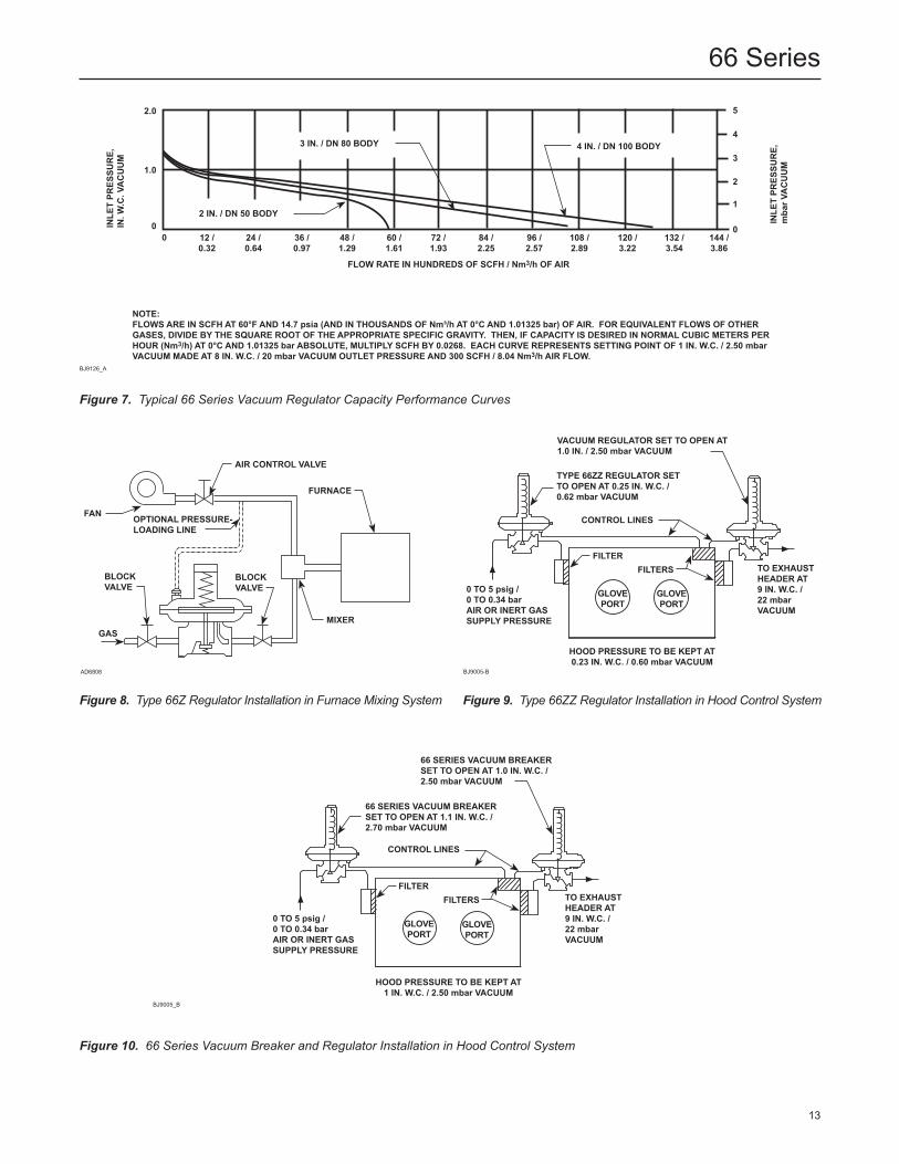
nOTE:FlOWS ARE In SCFh AT 60°F AnD 14.7 psia (AnD In ThOuSAnDS OF nm³/h AT 0°C AnD 1.01325 bar) OF AIR. FOR EQuIVAlEnT FlOWS OF OThER GASES, DIVIDE By ThE SQuARE ROOT OF ThE APPROPRIATE SPECIFIC GRAVITy. ThEn, IF CAPACITy IS DESIRED In nORMAl CuBIC METERS PER hOuR (nm3/h) AT 0°C AnD 1.01325 bar ABSOluTE, MulTIPly SCFh By 0.0268. EACh CuRVE REPRESEnTS SETTInG POInT OF 1 In. W.C. / 2.50 mbar VACuuM MADE AT 8 In. W.C. / 20 mbar VACuuM OuTlET PRESSuRE AnD 300 SCFh / 8.04 nm3/h AIR FlOW.
Figure 7. Typical 66 Series Vacuum Regulator Capacity Performance Curves
Figure 8. Type 66Z Regulator Installation in Furnace Mixing System Figure 9. Type 66ZZ Regulator Installation in Hood Control System
0 TO 5 psig /0 TO 0.34 barAIR OR InERT GASSuPPly PRESSuRE
TO ExhAuSThEADER AT9 In. W.C. / 22 mbar VACuuM
VACuuM REGulATOR SET TO OPEn AT1.0 In. / 2.50 mbar VACuuM
TyPE 66zz REGulATOR SETTO OPEn AT 0.25 In. W.C. /0.62 mbar VACuuM
COnTROl lInES
hOOD PRESSuRE TO BE KEPT AT0.23 In. W.C. / 0.60 mbar VACuuM
FIlTERFIlTERS
GlOVEPORT
GlOVEPORT
AIR COnTROl VAlVE
FAn OPTIOnAl PRESSuRE-lOADInG lInE
FuRnACE
mIXER
BlOCK VAlVE
BlOCK VAlVE
GAS
AD6808 BJ9005-B
2.0
1.0
0144 /3.86
132 /3.54
84 /2.25
96 /2.57
108 /2.89
120 /3.22
72 /1.93
12 /0.32
24 /0.64
36 /0.97
48 /1.29
60 /1.61
0
3 In. / Dn 80 BODy
2 In. / Dn 50 BODy
4 In. / Dn 100 BODy
5
4
0
1
2
3
InlE
T PR
ESSu
RE,
mbar V
ACuuM
InlE
T PR
ESSu
RE,
In. W
.C. VACuuM
FlOW RATE In hunDREDS OF SCFh / nm3/h OF AIR
Figure 10. 66 Series Vacuum Breaker and Regulator Installation in Hood Control System
BJ9005_B
0 TO 5 psig /0 TO 0.34 barAIR OR InERT GASSuPPly PRESSuRE
TO ExhAuSThEADER AT9 In. W.C. /22 mbarVACuuM
COnTROl lInES
GlOVEPORT
GlOVEPORT
66 SERIES VACuuM BREAKERSET TO OPEn AT 1.1 In. W.C. /2.70 mbar VACuuM
66 SERIES VACuuM BREAKERSET TO OPEn AT 1.0 In. W.C. /2.50 mbar VACuuM
hOOD PRESSuRE TO BE KEPT AT1 In. W.C. / 2.50 mbar VACuuM
FIlTERFIlTERS
13
66 Series
nOMInAlBODySIzE,In. / Dn
A
C
E G
nPT CastIron Body
nPT Steel Body
Cl125 FF Cast Iron or Cl150 RF(1) Steel Body
Cl300 RFSteel Body
Type 66or 66z
Type 66zz or 66 Series Vacuum
Regulator or Breaker
nPTSteel Body All Others
In. mm In. mm In. mm In. mm In. mm In. mm In. mm In. mm In. mm
2 / 503 / 804 / 100
7.25- - - -- - - -
184- - - -- - - -
9.25- - - -- - - -
235- - - -- - - -
10.0011.7513.88
254298353
10.50- - - -- - - -
267- - - -- - - -
13.8816.0018.00
353406457
15.0017.6221.25
381448540
21.3824.0027.63
543610702
3.31- - - -- - - -
84.1- - - -- - - -
3.254.625.38
82.6117137
1. Dimension also is same for 2 in. / DN 50 CL150 FF steel body.
C
E
G
A
A/2
COnTROl lInE COnnECTIOnFOR VACuuM REGulATOR
VEnTCOnnECTIOn
COnTROl lInE COnnECTIOn(WhEn uSED—STAnDARD OnVACuuM BREAKER)
BOTTOM FlAnGE lInE COnnECTIOn(STAnDARD On VACuuMREGulATOR OR BREAKER)
AD6045_F
Table 6. 66 Series Dimensions
Figure 11. 66 Series Dimensions
Ordering InformationWhen ordering, specify:
Application 1. Composition and specific gravity of gas (including chemical analysis if possible). 2. Range of temperatures, flowing inlet pressures (maximum, minimum, nominal) and pressure drops. 3. Desired outlet (control) pressure setting or range.
4. Range of flow rates (minimum controlled, maximum, normal). 5. Piping size(s).
ConstructionRefer to the Specifications section on page 2 and to each referenced table; specify the desired selection whenever there is a choice to be made. Always be sure to specify the regulator type number.
14
66 Series
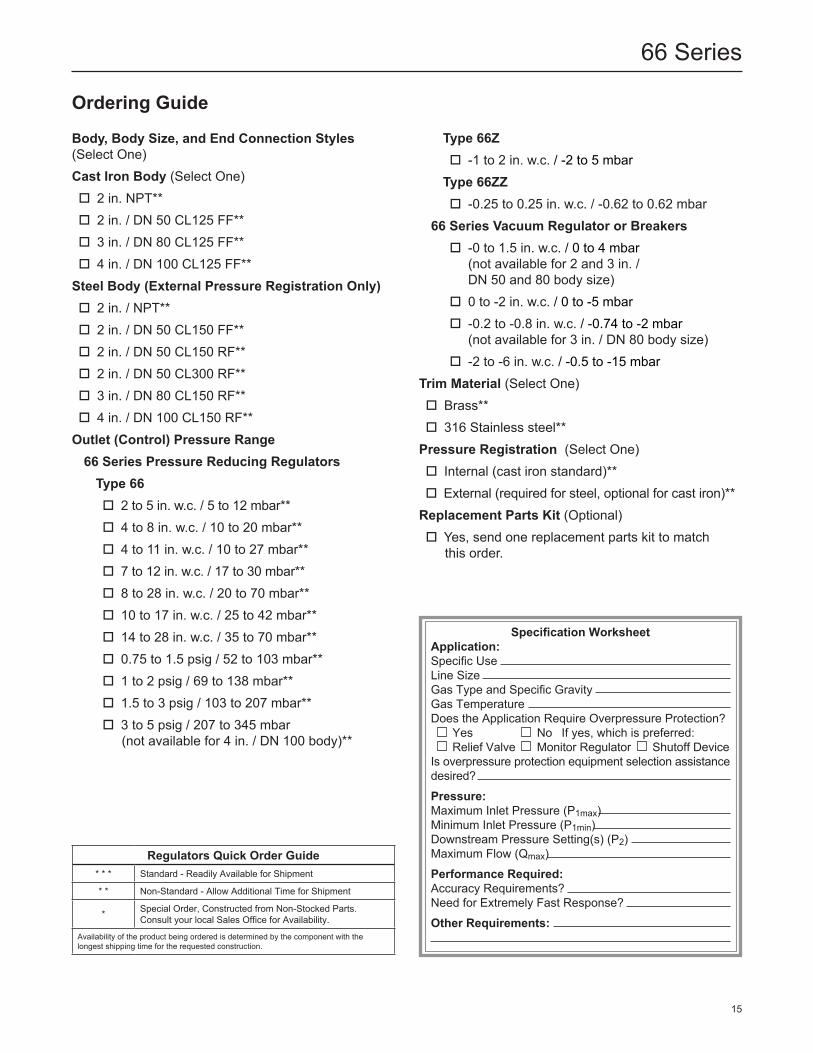
Ordering Guide
Body, Body Size, and End Connection Styles(Select One)Cast Iron Body (Select One) 2 in. NPT** 2 in. / DN 50 CL125 FF** 3 in. / DN 80 CL125 FF** 4 in. / DN 100 CL125 FF**Steel Body (External Pressure Registration Only) 2 in. / NPT** 2 in. / DN 50 CL150 FF** 2 in. / DN 50 CL150 RF** 2 in. / DN 50 CL300 RF** 3 in. / DN 80 CL150 RF** 4 in. / DN 100 CL150 RF**Outlet (Control) Pressure Range66 Series Pressure Reducing RegulatorsType 66 2 to 5 in. w.c. / 5 to 12 mbar** 4 to 8 in. w.c. / 10 to 20 mbar** 4 to 11 in. w.c. / 10 to 27 mbar** 7 to 12 in. w.c. / 17 to 30 mbar** 8 to 28 in. w.c. / 20 to 70 mbar** 10 to 17 in. w.c. / 25 to 42 mbar** 14 to 28 in. w.c. / 35 to 70 mbar** 0.75 to 1.5 psig / 52 to 103 mbar** 1 to 2 psig / 69 to 138 mbar** 1.5 to 3 psig / 103 to 207 mbar** 3 to 5 psig / 207 to 345 mbar (not available for 4 in. / DN 100 body)**
Type 66z -1 to 2 in. w.c. / -2 to 5 mbarType 66zz -0.25 to 0.25 in. w.c. / -0.62 to 0.62 mbar
66 Series Vacuum Regulator or Breakers -0 to 1.5 in. w.c. / 0 to 4 mbar
(not available for 2 and 3 in. / DN 50 and 80 body size)
0 to -2 in. w.c. / 0 to -5 mbar -0.2 to -0.8 in. w.c. / -0.74 to -2 mbar
(not available for 3 in. / DN 80 body size) -2 to -6 in. w.c. / -0.5 to -15 mbar
Trim Material (Select One) Brass** 316 Stainless steel**Pressure Registration (Select One) Internal (cast iron standard)** External (required for steel, optional for cast iron)**Replacement Parts Kit (Optional) Yes, send one replacement parts kit to match this order.
Regulators Quick Order Guide* * * Standard - Readily Available for Shipment
* * Non-Standard - Allow Additional Time for Shipment
* Special Order, Constructed from Non-Stocked Parts. Consult your local Sales Office for Availability.
Availability of the product being ordered is determined by the component with the longest shipping time for the requested construction.
Specification WorksheetApplication:Specific UseLine SizeGas Type and Specific GravityGas TemperatureDoes the Application Require Overpressure Protection? Yes No If yes, which is preferred: Relief Valve Monitor Regulator Shutoff DeviceIs overpressure protection equipment selection assistance desired?
Pressure:Maximum Inlet Pressure (P1max)Minimum Inlet Pressure (P1min)Downstream Pressure Setting(s) (P2)Maximum Flow (Qmax)
Performance Required:Accuracy Requirements?Need for Extremely Fast Response?
Other Requirements:
15
66 Series
66 Series
Facebook.com/EmersonAutomationSolutions
LinkedIn.com/company/emerson-automation-solutions
Twitter.com/emr_automation
Fisher.com
D100114X012 © 1971, 2018 Emerson Process Management Regulator Technologies, Inc. All rights reserved. 07/18. The Emerson logo is a trademark and service mark of Emerson Electric Co. All other marks are the property of their prospective owners. Fisher™ is a mark owned by Fisher Controls International LLC, a business of Emerson Automation Solutions.
The contents of this publication are presented for information purposes only, and while effort has been made to ensure their accuracy, they are not to be construed as warranties or guarantees, express or implied, regarding the products or services described herein or their use or applicability. All sales are governed by our terms and conditions, which are available on request. We reserve the right to modify or improve the designs or specifications of our products at any time without notice.
Emerson Process Management Regulator Technologies, Inc. does not assume responsibility for the selection, use or maintenance of any product. Responsibility for proper selection, use and maintenance of any Emerson Process Management Regulator Technologies, Inc. product remains solely with the purchaser.
Emerson Automation Solutions
Americas McKinney, Texas 75070 USA T +1 800 558 5853
+1 972 548 3574
Europe Bologna 40013, Italy T +39 051 419 0611
Asia Pacific Singapore 128461, Singapore T +65 6777 8211
Middle East and Africa Dubai, United Arab Emirates T +971 4 811 8100