Embed Size (px)
Citation preview

2250-R7
WAUKEE ENGINEERING Valve-Tronic 3.5 Installation And Operation Manual
NOTICE This manual contains important safety information and should be read and understood by all installation personnel and all users of this equipment.

2
2250-R7
2
TABLE OF CONTENTS
INTRODUCTION .................................................................................................................................................... 4
CONTROL VALVE OVERVIEW ............................................................................................................................. 5
SPECIFICATIONS ................................................................................................................................................. 6
INSTALLATION ...................................................................................................................................................... 7
FLO-METER INSTALLATION ............................................................................................................................................ 7 VALVE-TRONIC CONTROL VALVE INSTALLATION .............................................................................................................. 8 WIRING GUIDELINES ...................................................................................................................................................... 9 LOCATION OF VALVE-TRONIC WIRING ............................................................................................................................ 9
WIRING DIAGRAMS ............................................................................................................................................ 10
TERMINAL BLOCK WIRING DIAGRAM ............................................................................................................................. 10 QUICK DISCONNECT WIRING DIAGRAM ......................................................................................................................... 11
TYPICAL WIRING FORMATS .............................................................................................................................. 12
TYPICAL SOLEDOID VALVE WIRING ................................................................................................................ 13
CIRCUIT PROTECTION ...................................................................................................................................... 14
OVERVIEW OF VALVE-TRONIC ......................................................................................................................... 15
OPERATOR INTERFACE ................................................................................................................................................ 15 INSIDE THE VALVE-TRONIC .......................................................................................................................................... 16
OPERATION ........................................................................................................................................................ 16
MANUAL MODE ........................................................................................................................................................... 16 AUTOMATIC MODE ...................................................................................................................................................... 17 FAILURE MODES ......................................................................................................................................................... 17 PROGRAMMING MODE ................................................................................................................................................. 18
THUMBWHEEL ADJUSTMENT .......................................................................................................................... 22
ADDITIONAL FEATURES .................................................................................................................................... 23
DIRECT/REVERSE ACTING MODE ................................................................................................................................. 23 SET-POINT MODE SELECTION ...................................................................................................................................... 23 ERROR CODES ........................................................................................................................................................... 24
TROUBLE SHOOTING GUIDE ............................................................................................................................ 25
APPENDIX “A” - DRAWINGS ............................................................................................................................... 28
3
2250-R7
3
Table of Figures FIGURE 1 – VALVE-TRONIC FLO-METER........................................................................................................................ 7 FIGURE 2 – VALVE-TRONIC CONTROL VALVE ................................................................................................................ 8 FIGURE 3 – VALVE-TRONIC TERMINAL BLOCKS ............................................................................................................ 10 FIGURE 4 – QUICK DISCONNECT WIRING DIAGRAM ...................................................................................................... 11 FIGURE 5 – TYPICAL WIRING DIAGRAM WITH MONITOR ................................................................................................. 12 FIGURE 6 – TYPICAL WIRING DIAGRAM WITHOUT MONITOR ........................................................................................... 12 FIGURE 7 – AUXILIARY WIRING DIAGRAM .................................................................................................................... 12 FIGURE 8-10 – TYPICAL SOLENOID VALVE WIRING ...................................................................................................... 13 FIGURE 11 – IMPROPERLY WIRED SOLENOID VALVE .................................................................................................... 14 FIGURE 12 – OPERATOR INTERFACE ........................................................................................................................... 15 FIGURE 13 – INSIDE THE VALVE-TRONIC ...................................................................................................................... 16 FIGURE 14 –AUTOMATIC OPERATION 0 TO 50% .......................................................................................................... 17 FIGURE 15 – AUTOMATIC OPERATION 100 TO 50% ...................................................................................................... 17
Index of Tables
TABLE 1- WIRING CONTACTS DESCRIPTION ................................................................................................................ 10 TABLE 2- AUXILIARY WIRING CONTACTS DESCRIPTION ................................................................................................ 10 TABLE 3 - QUICK DISCONNECT WIRING ...................................................................................................................... 11

4
2250-R7
4
INTRODUCTION
The Purpose of this Manual Thank You for Purchasing a Valve-Tronic Flow Control Valve. This Manual shows you how to install, wire and maintain Waukee’s Valve-Tronic. It also helps you understand how to interface it to other devices in a control system. This manual contains important information and should be read and understood by all individuals who install, use or service this equipment.
Supplemental Manuals The 2004 “Waukee-Tronic Installation and Operation” Manual and 904 “Installation and Operation of Waukee Flo-Meters” Manual contain technical information as well as precautions about Waukee Flo-Meter’s.
Technical Support We strive to make our manuals the best in the industry. We rely on your feedback to let us know if we are reaching our goal. If you cannot find the solution to your particular application, or, if for any reason you need technical assistance, please call us at:
414-462-8200
Our technical support group will work with you to answer your questions. They are available Monday through Friday from 8:00 A.M. to 4:30 P.M. Central Standard Time. We also encourage you to visit our web site where you can find technical and non-technical information about our products and company.
http://www.waukeemeters.com http://www.group-upc.com
If you have a comment, question or suggestion about any of our products, services, or manuals, please e-mail or contact us by phone.
Conventions Used
When you see the “exclamation point” icon in the left-hand margin, the paragraph to its immediate right will be a warning. This information could prevent injury, loss of property, or even death in extreme cases. Any warning in this manual should be regarded as critical information that should be read in its entirety. The word WARNING or CAUTION in boldface will mark the beginning of the text.
Field Device
Refers to any device the Valve-Tronic connects to that accepts or sends a 4-20mA signal. (Ex. PLC, Chart Recorder, Controller)

5
2250-R7
5
CONTROL VALVE OVERVIEW The Waukee Valve-Tronic Control Valve is a flow controller specifically designed to control the fluid flow through a Waukee Flo-Meter. Principle of operation
The Waukee Valve-Tronic Control Valve is microprocessor based and compares a flow control signal (4-20 mA represents zero to full scale flow) to the actual flow signal produced by the Waukee-Tronic Flow Sensor on the Flo-Meter. If there is no difference between the control signal and the actual flow signal, the system is “satisfied” and the motor does not drive. If the flow signal is different from the control signal, the system will tell the motor to drive up or down until the flow signal matches the control signal. The Valve-Tronic is programmed to automatically “ramp” to a set point smoothly to limit “under” and “over shoot”.
The unit is factory “tuned” to each flow specification to provide smooth control action. The unit’s response and control is limited by the response of the customer-supplied controller, inlet pressure, flow range, gas type and downstream restrictions. If necessary, the Valve-Tronic may be “field tuned” for a variety of applications.
WARNING: This unit contains ESD (Electrostatic Discharge) sensitive parts and assemblies. Static control precautions are required when installing, testing, servicing or repairing this assembly. Component damage may result if ESD control procedures are not followed. If you are not familiar with static control procedures refer to an applicable ESD protection handbook.
WARNING: The Valve on this unit is not designed for positive shut-off. Valves may leak gas into equipment and cause asphyxiation or poisoning to personnel within confined space. If positive shut-off is desired install a mechanical valve prior to the flo-meter and verify that it is shut-off prior to servicing equipment attached to the unit. WARNING: Flo-Meter must be earth grounded. Ungrounded Flo-Meters may become a source of Ignition.

6
2250-R7
6
SPECIFICATIONS The Valve-Tronic Control Valve offers the following features:
Control and Waukee-Tronic Feedback diagnostic Indicators PID Style Control Error codes to aid in troubleshooting Shut off contacts to close the valve by opening a remote switch or contact Three Alarm contacts that cam be programmed for various alarm types Built in set-point generator which allows the unit to function from and internal set-
point Operating Voltage: 24 VDC +/- 10%
Power Consumption: 50 mA Signal Input: 4 -20 mA Standard Current Loop
Signal Output (from Waukee-Tronic): 4-20mA Isolated Current Loop Relay contact ratings: All 1.0 A@30VDC Maximum Operating Temperature: 150̊F (65˚C) Minimum Operating Temperature: 32˚F (0̊C)

7
2250-R7
7
INSTALLATION
Flo-Meter Installation The 904”Installation and Operation of Waukee Flo-Meters” manual contains instructions on the proper installation of the Flo-Meter. Refer to Figure 1 for reference and read all CAUTIONS and WARNINGS before proceeding.
The Valve-Tronic Flo-Meter is shipped as a complete unit as shown in Figure 1. Before installing the Flo-Meter, carefully remove the Waukee-Tronic Flow Sensor, to achieve this lay the unit on its side on a work bench or table. Then hold the Waukee-Tronic unit with one hand, while unscrewing the union nut counter clockwise with the other hand to loosen it.
CAUTION: Once the Waukee-Tronic is loose from the Flo-Meter make sure to pull the Waukee-Tronic from the Flo-Meter straight back off the float rod assembly. Moving the Waukee-Tronic to one side or another during removal may result in damage to the float rod assembly.
Once the Waukee-Tronic is free from the Flo-Meter, THE FLOAT ROD MUST NOT BE BENT OR DAMAGED IN ANY WAY. INACCURATE REDING MAY RESULT IF FLOAT ROD IS BENT. Remove the Float Rod Assembly and store it in a safe location until Flo-Meter body is mounted. Remove the red tape from the float rod and insert the float rod assembly into the Flo-Meter body. Then remove the sight glass tube from the Waukee-Tronic and fill the tube with Waukee Flo-Meter Oil so that the level of oil is approximately one (1) inch from the top. Note: Do not put oil in the sight glass tube of meters used for oxygen or methanol service. Oxygen Flo-Meters should be run dry, or with distilled water. Flo-Meters for Methanol service will automatically fill the sight glass tube with Methanol when in service. Place the sight glass tube back into the Waukee-Tronic, making sure the sight glass tube o-ring is properly seated, and then carefully install the Waukee-Tronic on to the Flo-Meter.
WARNING: Do not fill the sight glass tube with Flo-Meter oil on meters used for oxygen service. Use of oil may cause fire or explosion. Serious personal injury may result from fire or explosion.
Note: If the Valve-Tronic is shipped separately to be installed in an existing Flo-Meter, please refer to the “Valve-Tronic Control Valve Installation on the following page.
% FLOW
Figure 1

8
2250-R7
8
Valve-Tronic Control Valve Installation The following instructions are for installing a Valve-Tronic Control Valve onto an existing Waukee Flo-Meter. Please refer to Figure 2.
1. First remove the valve assembly from the Valve-Tronic as follows: i. Remove the Four (4) access window cover plate
screws and the access window cover plate. ii. Loosen the valve stem coupling lower hex head
set screw. iii. Loosen the valve body union nut. iv. Carefully separate the valve body assembly from
the adapter block. v. Set the Valve-Tronic and valve body assembly
aside. 2. Remove the cap or manual valve from the existing
Flo-Meter using the valve tool provided. 3. Inspect the top of the Flo-Meter and remove any of
the following if present: Valve orifice, orifice gasket or valve spring.
4. Insert the “O-Ring” into the top of the Waukee Flo-Meter. Ensure that the “O-Ring” is seated flat against the “shelf” of the Flo-Meter.
5. Insert the orifice on top of the “O-Ring” and ensure that the “O-Ring” is still seated properly.
6. Screw the valve body assembly into top of the Flo-Meter using the valve tool. Tighten until the flat gasket is seated in the Flo-Meter body.
CAUTION: Do not over tighten as damage to the threads may occur.
7. Install the Valve-Tronic onto the valve body
assembly. Carefully align the valve stem coupling to the valve stem.
CAUTION: Do not force the Valve-Tronic onto the valve stem.
8. Tighten the union nut by hand until there is little or no
play between the valve body assembly and Valve-Tronic.
9. Tighten the valve stem coupling lower hex head set screws.
10. Replace the access window cover plate and Four (4) access window cover plate screws.
% FLOW
Figure 2

9
2250-R7
9
Wiring Guidelines Your company may have guidelines for wiring installation. If so, you should check those before you begin the installation. Here are some general things to consider:
Use the shortest wiring route whenever possible. Use shielded wiring and ground the shield at the Field Device end. DO NOT
ground the shield at both the Valve-Tronic and Field Device. Do not run the signal wiring next to large motors, high current switches, or
transformers. This may cause noise problems. Route the wiring through an approved cable housing to minimize the risk of
accidental damage. Check local and national codes to choose the correct method for your application.
Be sure to leave enough slack in the cables to allow easy removal of the Waukee-Tronic and Valve-Tronic from the Flo-Meter for maintenance. If seal tight or similar conduit is used, be sure to provide an adequate loop of conduit for maintenance access.
CAUTION: To reduce the risk of electrical shock and also to prevent damage to the Waukee-Tronic, Valve-Tronic and the Field Device the Waukee-Tronic is connecting to. It is advised to turn off the supply power to the Waukee-Tronic, Valve-Tronic and Field Device before connecting or disconnecting any wires.
Location of Valve-Tronic Wiring The Standard Valve-Tronic Control Valve wiring terminals are located at the top of the Valve-Tronic Control unit under the top cover. Remove the Four-(4) top cover screws and top cover to access the wiring terminals. The wiring terminals are a combination screw terminal/quick disconnect arrangement. The terminal block(s) may be removed by loosening the two screws located on either side of the terminal blocks. Note: Be sure to feed your wiring through suitable bushings in the knockout(s) before wiring the terminal blocks. All connections to the unit should be made in accordance with Figures 5-7 and Tables 1&2. Use 18 or 20 AWG wire for all connections. If Valve-Tronic is equipped with the optional Quick Disconnect plug, the quick disconnect plug is a 19 pin plug pre-wired with three cables. The cables are as follow: One 4 conductor cable with a pre-wired plug on the end to connect to the Waukee-Tronic. One 7 Conductor Cable that contains all the power, control, and feedback signal wiring and one 9 conductor cable that includes all the relay logic wiring. Refer to Figure 4 and Table 3. The Quick Disconnect plug can be added to any new or existing Valve-Tronic’s. The Part Number for the Quick Disconnect cable assembly is 1-3481* Note: For “S” series of Flo-Meter’s add a “-S” after the part number.

10
2250-R7
10
WIRING DIAGRAMS Terminal Block Wiring Diagram
Table 1 Contact Description
1 Ground for Shield
2 + 24 VDC
3 DC Common
4 + 4 to 20 mA Control Signal from Field Device
5 - 4 to 20 mA Control Signal from Filed Device
6 + 4 to 20 mA Waukee-Tronic Flow Sensor Signal
7 -4 to 20 mA Waukee-Tronic Flow Sensor Signal
8 +4 to 20 mA Waukee-Tronic Monitor Loop Signal (shipped jumpered to pin 9)
9 -4 to 20 mA Waukee-Tronic Monitor Loop Signal (shipped jumpered to pin 8)
Table 2 Contacts Description 10&11 Alarm 1 (1.0 A@30VDC, N.O. Relay Contacts)
12&13 Alarm 2 (1.0 A@30VDC, N.O. Relay Contacts)
14&15 Alarm 3 (1.0 A@30VDC, N.O. Relay Contacts)
16&17 Unconditional “Close Valve” contacts, Valve drives closed and remains closed until circuit is complete (contacts 16 and 17 are closed), Shipped jumped
Figure 3

11
2250-R7
11
Quick Disconnect Wiring Diagram
V-T Terminal Number
Quick-Disconnect Terminal Number
Wire Color Signal
1 A Ground for shield 2 B RED +24VDC Power 3 C BLACK DC Common 4 D BLUE +4..20 mA Control 5 E ORANGE -4..20 mA Control 8 H GREEN +4..20 mA Flow Monitor 9 J WHITE -4..20 mA From Monitor
6 F GREEN +4..20 mA From Waukee-Tronic 7 G WHITE -4..20 mA From Waukee-Tronic - U BLACK -24VDC to Waukee-Tronic - V RED +24VDC to Waukee-Tronic
10 K BLUE Alarm 1 Commom 11 L YELLOW Alarm 1 N.O. Contact 12 M VILOET Alarm 2 Common 13 N ORANGE Alarm 2 N.C. Contacts 14 P BLACK Alarm 3 Common 15 R WHITE Alarm 3 N.O. Contacts 16 S RED Close Valve Control Contacts 17 T BROWN Close Valve Control Contacts
Table 3
Figure 4

12
2250-R7
12
TYPICAL WIRING FORMATS The figures shown below are for typical wiring configurations. If connecting the Valve-Tronic to a controller and data acquisition module or chart recorder, refer to Figure 5. If connecting the Valve-Tronic to controller only, refer to Figure 6. For auxiliary contact wiring, refer to Figure 7.
Auxiliary Contact Wiring
WARNING: The Auxiliary contacts are rated for 1.0A @30VDC. Use of an external relay is highly recommended. Excessive current draw on these contacts will result in damage to the Valve-Tronic control board.
Figure 6 Figure 5
Figure 7

13
2250-R7
13
TYPICAL SOLENOID VALVE WIRING There are many combinations of wiring configurations when connecting a solenoid valve to a Valve-Tronic Flo-Meter. The figures shown below are typical wiring diagrams when using a N.C. (Normally Closed) Solenoid.
Figure 8 does not require a set of N.C. (Normally Closed) contacts from a controller as shown unless desired. Alarm 3 contacts must be programmed to engauge when low limit switch is met (P16 = “LLA”) for proper operation. Operation is as follow: when the control signal goes to 4mA the motor will drive the valve closed until the Low Limit Switch is met which closes contacts 14 & 15 “Solenoid Contacts” and energize the relay to close the solenoid valve.
Figure 9 requires one set of N.C. (Normally Closed) contacts and one set of N.O. (Normally Open) contacts from a controller. Both outputs from the controller should be setup to engage at the same time. Operation is as follow: When solenoid valve contacts are opened the solenoid valve will close and stop flow instantaneously and at the same time contacts 16 & 17 “Closed Valve Contacts” are opened and the Valve-Tronic drives fully closed.
Figure 10 requires one N.O. (Normally Open) set of contacts from a controller and operates the same manner as Figure 9. (Note: When contacts 16 & 17 are opened the Valve-Tronic will lock up until these contacts are closed.)
CAUTION: When using a solenoid valve be sure to select the proper solenoid configuration for fail safety (N.O. or N.C.)
Figure 8 Figure 9 Figures 10

14
2250-R7
14
Improperly Wired Solenoid Valve Caution: Do Not connect a solenoid valve to a Valve-Tronic Flo-Meter as shown in figure 11. Damage may occur to float rod assembly due to spiking.
Figure 11
CIRCUIT PROTECTION The Valve-Tronic is equipped with a circuit breaker. This circuit breaker automatically resets after the fault is removed and power is recycled to the unit. The Waukee-Tronic is equipped with fuse protection as well, refer to Waukee-Tronic manual for location and fuse replacement.

15
2250-R7
15
OVERVIEW OF VALVE-TRONIC Operator Interface
1. Control loop Diagnostic Indicator lluminates when the control loop is broken or if the signal is below 3.5 mA or above 20.5 mA. “1 Second Flashes” when “Internal Set-point” mode is selected.
2. Waukee-Tronic Flow Sensor Loop (feedback loop) Diagnostic Indicator Illuminates when the loop is broken or if the signal is below 3.5mA or above 20.5mA.
3. VOLTS – N/A
4. Automatic Mode Selector Key Valve position is automatically controlled.
5. Automatic Mode Indicator Illuminated when in Automatic mode.
5. Manual Mode Selector Key Valve position is controlled by UP/Down keys.
6. Manual mode indicator Illuminated when in Manual mode.
8. Hi Limit Indicator Illuminates when valve is physically at full open travel. “1 Second Flashes” during motor drive to indicate motor is driving the valve open
9. Motor Drive Indicator Indicator will “pulse” at various rates when in operation to indicate relative motor drive speed.
10. Low Limit Indicator Illuminates when valve is approaching closure. “1 Second Flashes” during motor drive to indicate motor is driving the valve closed.
11. % Flow Display
Displays actual % flow feedback from Waukee-Tronic. Used during programming mode to change parameters of the valve. Informs the operator of any errors or alarms.
12. “UP” valve drive selector key. When pressed and held the motor will
start driving the valve open at the low speed and ramp to the high speed.
13. “DN” valve drive selector key.
When pressed and held the motor will start driving the valve closed at the low speed and ramp to the high speed.
14. Valve-Tronic Identification Plate
Identifies the unit and rated conditions the unit was manufactured to meet.
% FLOW
Figure 12

2250-R7
Inside the Valve-Tronic
OPERATION
Manual Mode When In Manual Mode the Manual mode indicator will be illuminated and the % Flow display will indicate the position of the valve within the automatic control range in percent of flow.
In the Manual mode, the / drive keys will drive the motor and thus drive the valve open or closed when pressed.
If the key is pressed and held the motor will start driving the valve at the Low speed and slowly ramp to the High speed driving the valve open until the valve reaches it’s physical top limit, the “HI” indicator will illuminate and the motor will stop driving.
If the key is pressed and held the motor will start driving the valve at the Low speed and slowly ramp to the High speed driving the valve closed until the valve reaches it’s closed position resulting in the “Low” indicator will illuminate.
Figure 13
17
2250-R7
17
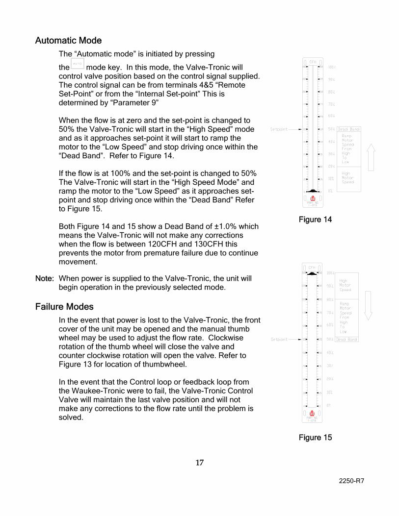
Automatic Mode
The “Automatic mode” is initiated by pressing
the mode key. In this mode, the Valve-Tronic will control valve position based on the control signal supplied. The control signal can be from terminals 4&5 “Remote Set-Point” or from the “Internal Set-point” This is determined by “Parameter 9” When the flow is at zero and the set-point is changed to 50% the Valve-Tronic will start in the “High Speed” mode and as it approaches set-point it will start to ramp the motor to the “Low Speed” and stop driving once within the “Dead Band”. Refer to Figure 14. If the flow is at 100% and the set-point is changed to 50% The Valve-Tronic will start in the “High Speed Mode” and ramp the motor to the “Low Speed” as it approaches set-point and stop driving once within the “Dead Band” Refer to Figure 15. Both Figure 14 and 15 show a Dead Band of ±1.0% which means the Valve-Tronic will not make any corrections when the flow is between 120CFH and 130CFH this prevents the motor from premature failure due to continue movement.
Note: When power is supplied to the Valve-Tronic, the unit will begin operation in the previously selected mode.
Failure Modes
In the event that power is lost to the Valve-Tronic, the front cover of the unit may be opened and the manual thumb wheel may be used to adjust the flow rate. Clockwise rotation of the thumb wheel will close the valve and counter clockwise rotation will open the valve. Refer to Figure 13 for location of thumbwheel.
In the event that the Control loop or feedback loop from the Waukee-Tronic were to fail, the Valve-Tronic Control Valve will maintain the last valve position and will not make any corrections to the flow rate until the problem is solved.
Figure 14
Figure 15

18
2250-R7
18
Programming Mode
There are two separate programming menus. The first menu (Menu A) is accessible by
pressing , , keys all at the same time.
The second menu (Menu B) is accessible by pressing , , keys all at the same time. When the CONT, HIGH, LOW, AUTO, and MAN indicators are all illuminated you are in the programming menu and the % Flow display will toggle with “P x and the value of the parameter (Note: x equals the current parameter number)
Menu A
HIGH SPEED (Parameter – 1) – High Motor Speed Display flashes “P 1” and the “Current Value”
Value can be changed from “0” to “100”, where “0” is the slowest speed, and
“100” is the fastest by pressing the or key.
Press key to go to the next parameter.
LOW SPEED (Parameter – 2) – Low Motor Speed Display flashes “P 2” and the “Current Valve”
Value can be changed from “0” to “100”, where “0” is the slowest speed, and
“100” is the fastest by pressing the or key.
Press key to go to the next parameter.
DEAD BAND (Parameter – 3) – Band from set-point that the Valve-Tronic is satisfied. For an explanation of this parameter see “Operation” – “Automatic Mode” pg.17
Display flashes “P 3” and the “Current Valve” Value can be changed from “0.0” to “5.0”, where “0.0” is the lowest dead band
(+/- 0%), and “5.0” is the highest (+/- 5%) by pressing the or key. NOTE: a value of “0.0” may result in premature failure of the motor.
Press key to go to the next parameter.

19
2250-R7
19
RAMP SPEED BAND (Parameter – 4) - % Flow from Set-point that the Valve-Tronic starts to ramp from the “High Speed” to “Low Speed”
Display flashes “P 4” and the “Current Valve” Value can be changed from “0” to “35”, where “0” is no ramp to low speed and
“35” is the largest band setting (+/-35% around the set point).
Pressing or keys changes the SPEED RAMP START.
Press key to go to the next parameter.
MANUAL MODE LOCKOUT (Parameter – 5) – Locks the unit in Automatic mode. Display flashes “P 5” and “Current Setting”
Setting can be changed by pressing the or key, where:
Enb - “Manual” Mode enabled – Default Setting dSb - “Manual” Mode disabled
Press key to go to the next parameter.
SETPOINT MODE (Parameter – 6) - Selects source of Set-point Display flashes “P 6” and “Current Setting”.
Setting can be changed by pressing the or key, where:
“rSP” – Remote Set-point from controller (Terminals 4 and 5) - Default Setting “ISP” – Internal Set-point mode
Press key to go to the next parameter
CORRECTION DELAY TIME (Parameter – 7) - Once within deadband, the amount of time delay before adding correction to bump PV to equal SP.
Display flashes “P 7” and “Current Setting”.
Value can be changed from “0” to “15” seconds by pressing the or keys.
Press key to go to the next parameter

20
2250-R7
20
VALVE SCALING FACTOR (Parameter – 8) - Scale of control valve (Note : Do not chnage unless instructed by the manufacture)
Display flashes “P 8” and “Current Setting”. Value can be changed from “0.15” to “1.00” where “0.15” is the smallest scale,
and “1.00” is full scale by pressing the or keys.
Press key to exit and return to normal operation
Menu B
DIRECT/REVERSE ACTING MODE (Parameter –11) – Changes mode of operation. For additional information on setting this parameter go to “Additional Features” – “Direct/Reverse Acting Mode”
Display flashes “P 11” and the “Current Value”
Setting can be changed by pressing the or key, where: dA - “Direct” Acting Mode - default setting rA - “Reverse” Acting Mode
Press key to go to the next parameter.
SPLIT RANGE CONTROL (Parameter – 12) – Sets the Control Signal range. Display flashes “P 6” and “Current Setting”
Setting can be changed by pressing the or key, where:
”420” – 4-20mA Control Signal Range –Default Setting “412” – 4-12mA Control Signal Range “122” – 12-20mA Control Signal Range
Press key to go to the next parameter.
VALVE SEATING TIME DELAY (Parameter –13) – Amount of time the valve drives closed once the “Low Limit Switch” is meet.
Display flashes “P13” and the “Current Value”
Value can be changed from “0” to “40” seconds by pressing the or key.
Press key to go to the next parameter.

21
2250-R7
21
ALARM 1 TYPE (Parameter –14) – Select event to trigger alarm 1 (Contacts 10&11)
Setting can be changed by pressing the or key, where: “dSb” – Diabled – Default Setting “Au” – Auto/Manual Mode – triggers when unit is in the “manual” mode “HLA” – High Limit Alarm – triggers when “top limit switch” is met “LLA” – Low Limit Alarm – triggers when “low limit switch” is met “Err” – Error Alarm – triggers when an error occurs “HFA – High Flow Alarm – triggers when the flow is above “High Flow Alarm” Set-point (Parameter 18) “LFA – Low Flow Alarm – triggers when the flow is below “Low Flow Alarm” Set-point (Parameter 19)
Press key to go to the next parameter.
ALARM 2 TYPE (Parameter –15) – Select event to trigger alarm 1 (Contacts 12&13)
Setting can be changed by pressing the or key, where: “dSb” – Disabled– Default Setting “Au” – Auto/Manual Mode – triggers when unit is in the “manual” mode “HLA” – High Limit Alarm – triggers when “top limit switch” is met “LLA” – Low Limit Alarm – triggers when “low limit switch” is met “Err” – Error Alarm – triggers when an error occurs “HFA – High Flow Alarm – triggers when the flow is above “High Flow Alarm” Set-point (Parameter 18) “LFA – Low Flow Alarm – triggers when the flow is below “Low Flow Alarm” Set-point (Parameter 19)
Press key to go to the next parameter.
ALARM 3 TYPE (Parameter –16) – Select event to trigger alarm 1 (Contacts 14&15)
Setting can be changed by pressing the or key, where: “dSb” – Disabled – Default Setting “Au” – Auto/Manual Mode – triggers when unit is in the “manual” mode “HLA” – High Limit Alarm – triggers when “top limit switch” is met “LLA” – Low Limit Alarm – triggers when “low limit switch” is met “Err” – Error Alarm – triggers when an error occurs “HFA – High Flow Alarm – triggers when the flow is above “High Flow Alarm” Set-point (Parameter 18) “LFA – Low Flow Alarm – triggers when the flow is below “Low Flow Alarm” Set-point (Parameter 19)
Press key to go to the next parameter.

22
2250-R7
22
HIGH FLOW ALARM SET-POINT (Parameter –17) – Set-point to trigger a High Flow Alarm. NOTE: Alarm 1,2 or 3 must be set to “HFA” for alarm to trigge
Display flashes “P13” and the “Current Value”
Value can be changed from “0” to “100” % by pressing the or key.
Press key to go to the next parameter.
LOW FLOW ALARM SET-POINT (Parameter –18) – Set-point to trigger a Low Flow Alarm. NOTE: Alarm 1,2 or 3 must be set to “LFA” for alarm to trigger.
Display flashes “P13” and the “Current Value”
Value can be changed from “0” to “100” % by pressing the or key.
Press key to exit and return to normal operation.
THUMBWHEEL ADJUSTMENT The Thumbwheel adjustment is critical in the operation of the Valve-Tronic. If the Thumbwheel does not make contact with the “Low Limit Switch” it could cause undesirable operation. The Thumbwheel is set at the factory to engage the “Low Limit Switch” at about 5% of flow. For an overview of the location of these components see Figure 13. In the event that you are experiencing problems with the valve sticking or you are not satisfied with the operation of the “Low Limit Switch” you will need to adjust the thumbwheel. To achieve this, start with the Valve-Tronic in the Manual mode and drive the valve to the lowest valve position. Then loosen the set screw located on the thumbwheel collar. Once the thumbwheel is free you will be able to slide it up and down on the drive shaft. Adjust the thumbwheel until it just engages the “Low Limit Switch” then tighten the set screw to secure the thumbwheel in place. Test the adjustment by driving the valve until the “Low” Indicator light extinguishes, then drive the valve closed and note at what % flow the “Low” Indicator Illuminates. If you are satisfied with the operation of the thumbwheel, the unit can be returned to normal operation, if you are unsatisfied reset the thumbwheel again as described above until satisfied with its operation.

23
2250-R7
23
ADDITIONAL FEATURES
Direct/Reverse Acting Mode
The Valve-Tronic is capable of operating in either “Direct” or “Reverse” acting modes. In “Direct” acting mode a 4mA control signal corresponds to the 0% Automatic Control Position while a 20mA control signal sends the Valve-Tronic to the 100% Automatic Control Position. In “Reverse” acting mode a 4 mA control signal corresponds to the 100% Automatic Control Position while a 20mA control signal sends the Valve-Tronic to the 0% Automatic Control Position as indicated in the following chart:
Direct Acting Mode Reverse Acting Mode
Control Signal
Automatic Control Position
Control Signal
Automatic Control Position
4mA
12mA
20mA
0 %
50%
100%
4mA
12mA
20mA
100 %
50%
0%
Note: The Valve-Tronic is factory preset to “Direct” Acting Mode.
Set-point Mode Selection
The Valve-Tronic is capable of operating in either “Internal” or “Remote” Set-point Mode. The mode of operation is set by “Parameter 6” (Refer to Progrmming mode Pg.18.) When Parameter 6 is set to “rSP” (Remote Set-Point) the Valve-Tronic
compares a 4-20mA signal on the control input terminals 4 and 5 with the Waukee-Tronic’s feedback signal and adjusts the valve position to where these two values are equal to each other.
When Parameter 6 is set to “ISP” (Internal Set-point) the set-point is set by
pressing and holding the key for 5 seconds. Once in set-point mode the % flow display will toggle between “SP” and the “Current Set-Point”. This value can be set from 0% to 100% flow. The Valve-Tronic compares this set-point value with the Waukee-Tronic’s feedback signal and adjusts the valve position to where these two values are equal to each other. Note: When internal set point mode is selected the “CONT” light will flash continually to inform the user that the Valve-Tronic is in “Internal Set-point Mode”.

24
2250-R7
24
Error Codes
The Valve-Tronic Control Valve not only includes visual diagnostic light indicators to aid with troubleshooting, but it also displays error codes when a problem arises. When the Valve-Tronic Control Valve detects an error it will display each error code for a few seconds as “Ex” (Note: “x” equals the error code) and continue to cycle until all errors are resolved. Below is a table of error codes and what they are.
Error Code Problem
E1 Waukee-Tronic loop below 3.5mA or open (Contacts 6&7) E2 Waukee-Tronic loop above 20.5mA (Contacts 6&7) E3 Control Input below 3.5mA or open (Contacts 4&5) E4 Control Input loop above 20.5mA (Contacts 4&5) E5 When Waukee-Tronic input is below 4.5mA and top limit switch is met (Indicates
that the fluid flow is blocked) CLd Closed Valve Contacts are open (Contacts 16&17) AL1 Alarm 1 has tripped AL2 Alarm 2 has tripped AL3 Alarm 3 has tripped

25
2250-R7
25
TROUBLE SHOOTING GUIDE
PROBLEM
SYMPTOMS
PROBABLE CAUSE
RECOMMENDED ACTION Valve-Tronic does not operate.
The % Flow display is dark. Waukee-Tronic may be dark
Loss of 24 VDC power and/or polarity reversal. Circuit Breaker tripped Power supply voltage is less than 21VDC.
Check 24VDC supply. Check all electrical connections. Cycle power to reset circuit breaker
Valve-Tronic does not operate in “AUTO” or "MANUAL" mode.
The Flow indicator on the Flo-Meter remains at a constant flow even while the "UP/DN" button is operated in Manual Mode. Display Reads “CLd”
Loose motor connection Failed Stepper Motor Terminals 16 & 17 are open
Check the motor connector and wires. Send back to Waukee for repair Check for closure between terminals 16 & 17
Valve-Tronic does not operate in "AUTO" mode and the valve position or flow rate does not change.
The "CONT" light is “ON”. Display Reads “E3” or “E4”
Loss of control signal on terminals 4 & 5 Control signal to terminals 4 & 5 is above 20.5mA
Check Field Device output signal (4-20 mA) to terminals 4 & 5. Check wiring between Field Device and Valve-Tronic
Vale-Tronic is working flawlessly in "MAN" mode.
In Manual mode the Valve-Tronic controls the flow rate.
Reversed signal polarity on terminals 4 & 5
Check polarity on terminals 4 & 5.
No gas flow observed on Flo-Meter
Valve-Tronic “HI” indicator may be “ON” Display Reads “E5”
Blockage in the gas line before or after the Flo-Meter. Loss of gas supply.
Check for closed valves (solenoids). Check gas supply
“LOW” Limit indication light does not work.
“LOW” light is “OFF” even when valve is fully closed. Valve may be sticking
“Low limit” switch is out of adjustment. Loose limit switch connector or faulty switch
Adjust the thumbwheel as described on pg. 21 Check the limit switch connector and wires.
Intermittent blinking of indicators and % Flow display, Especially during valve operation
“CONT” indicator flashes intermittently and % Flow flashes zero
Power supply unable to provide enough current. 24VDC wiring not proper gauge wire.
Bigger power supply may be needed. Install 18-20AWG Shielded Cable
Valve-Tronic stops controlling and appears to be in Programming Mode
“CONT”, “HIGH”, “LOW”, “AUTO”, “MAN” LIGHTS ALL ILLUMINATED “%Flow” display toggles between “P_” and “Number”
Leaky Ignition Transformer RF Noise
Use Shielded cable with shield grounded on Field Device end only!! Follow wiring guidelines on pg 9 Find and replace leaky Ignition Transformer

26
2250-R7
26
EXPRESS WARRANTY ON WAUKEE EQUIPMENT WAUKEE warrants its products for a period of one (1) year from date of shipment from WAUKEE to the original purchaser to be free from defects in material and workmanship under normal recommended use, service, inspection and maintenance. Normal recommended use, service inspection and maintenance mean: 1. Not to be used in excess of nor below the rated capacity, pressures and temperature ranges specified in the applicable quotation, purchase order, acknowledgment, marketing literature, nameplate(s), specification sheet or the Installation, Operation, Inspection and Maintenance Manual (THE MANUAL); 2. Using only clean liquids or gases (only liquids in liquid Flo-Meters and only gases in gas Flo-Meters); air and fuel gases used in mixing equipment to be clean and free of solids all as further explained in THE MANUAL; and 3. Installation, operation, inspection and maintenance in compliance with THE MANUAL; and 4. The WAUKEE products being used only in: a. Ambient environments lower than 132° Fahrenheit (54° Celsius) unless specifically designed and so labeled by WAUKEE for higher temperatures; and b. Non-corrosive environments; and c. Completely protected from moisture, rain, snow or other outside environments; and d. Not to be used below 32° Fahrenheit (0° Celsius) unless special precautions are taken for low temperature conditions as shown in THE MANUAL. 5. Being used only for applications permitted by THE MANUAL or other WAUKEE literature or special applications approved in a separate written authorization by WAUKEE. WARRANTY EXCEPTIONS This Warranty does not apply to damage caused by any or all of the following circumstances or conditions: 1. Freight damage; 2. Parts, accessories, materials or components not obtained from nor approved in writing by WAUKEE; 3. Any consequential or incidental damages including but not limited to loss of use, loss of profits, loss of sales, increased costs, arising from the use of any product,
system or other goods or services manufactured, sold or provided by WAUKEE; 4. Misapplication, misuse and failure to follow THE MANUAL or other literature, instructions or bulletins (including drawings) published or distributed prior to THE MANUAL. The exclusive remedy under this Warranty or any other express warranty is the repair or replacement without charge for labor and materials of any WAUKEE parts found upon examination by WAUKEE to have been defective. Since certain WAUKEE equipment is heavy, bulky and not deliverable by U.S. mail or other parcel service, WAUKEE equipment may be returned only upon written consent of WAUKEE and then only to the location designated by WAUKEE. Generally such consent will be given only upon the condition that the customer assume and prepay all carrier charges and responsibility for damage in transit. Purchasers of WAUKEE products, equipment, goods or services waive subrogation on all items covered under their own or any other insurance. DISCLAIMER THIS WARRANTY IS EXCLUSIVE. WAUKEE EXPRESSLY DISCLAIMS ANY AND ALL OTHER WARRANTIES WHETHER EXPRESS OR IMPLIED INCLUDING ANY IMPLIED WARRANTY OF MERCHANTABILITY OR FITNESS FOR A PARTICULAR PURPOSE OR ANY PURPOSE. No person, including any dealer, seller or other representative of WAUKEE is authorized to make, on behalf of WAUKEE, any representations beyond those contained in WAUKEE literature and documents or to assume for WAUKEE any obligations or duties not contained in this Warranty and Warranty Policy. WAUKEE reserves the right to make design and other changes, modifications or improvements to its products, services, literature or systems, without any obligation, to furnish or install same on any previously sold or delivered products or systems. LIMITATION OF LIABILITY It is expressly agreed that the liability of WAUKEE is limited and WAUKEE does not function as an insurer. The purchaser and/or user agree that WAUKEE is not liable for loss, harm or damage due directly or indirectly to any occurrence or consequences therefrom. If WAUKEE should be found liable to anyone on any theory (except any express warranty where the remedy is set

27
2250-R7
27
forth in Section 2 of this Warranty and Warranty Policy) for loss, harm or damage, the liability of WAUKEE shall be limited to the lesser of the actual loss, harm or damage or the purchase price of the involved WAUKEE equipment or service when sold (or when service performed) by WAUKEE to its customer. This liability is exclusive and regardless of cause or origin resulting directly or indirectly to any person or property from: 1. The performance or nonperformance of any obligations set forth in this Warranty and Warranty Policy: 2 Any agreement including specifications between WAUKEE and the customer; 3 Negligence, active, passive or otherwise of WAUKEE or any of its agents or employees; 4. Breach of any judicially imposed warranty or convenant of workmanship, durability or performance; and 5. Misrepresentation (under the Restatement, common law or otherwise) and/or strict liability involvement. 6. Liability for fraud-in-the-inducement. INFORMATION NECESSARY TO OBTAIN TECHNICAL ASSISTANCE. For WAUKEE to appropriately respond to a request for assistance or evaluation of customer or user operating difficulty. Please provide at a minimum the following information: 1. Serial number and type or model of meter, compressor or other equipment and all other data shown on the nameplate and on the specific component which appears to be involved in the difficulty; 2. The date and from whom you purchased your WAUKEE equipment and your purchase order number.
3. State your difficulty, being sure to mention at least the following: 4. Application. 5. Input pressure where Flo-Meters or compressors are involved. 6. Condition of filters, strainers or screens, upstream or downstream of the WAUKEE equipment. 7. Gas or liquid temperatures and other ambient conditions at the time of the difficulty. 8. Type of lubrication being used (if any) - give specifics. 9. Any other relevant pressures including gauge readings both upstream and downstream of the WAUKEE equipment. 10. All electrical information available. 11. Performance activity. 12. Any other pertinent information. If a sketch would help explain the difficulty, please include one. WARRANTY FIELD SERVICE If warranty Field Service at the request of the purchaser or user is rendered and the difficulty is found not to be with WAUKEE's product, the purchaser shall pay the time and expense (at the prevailing rate at the time of the service) of WAUKEE's field representative(s). Charges for service, labor and other expenses that have been incurred by the purchaser, its customer or agent without written approval of WAUKEE will not be accepted. The OEM or other reseller is responsible for transmitting installation and operating instructions, THE MANUAL or other service literature supplied by WAUKEE with the equipment.

28
2250-R7
28
APPENDIX “A” - DRAWINGS

10
2250-R7
10
WAUKEE ENGINEERING COMPANY, INC. 5600 West Florist Avenue, Milwaukee, WI 53218, U.S.A. Phone: (414) 462-8200 Fax: (414) 462-7022 e-mail: [email protected] web: www.waukeemeters.com www.group-upc.com


![(GJH &RJQLWLYH 6ROXWLRQV ZLWK 0LFURVRIW ,R7easdam.blob.core.windows.net/iotinaction...,r7 (gjh,r7 $]xuh 6skhuh26,r7:lqgrzv ,r7 /lqx[$]xuh,r7 (gjh &rpsdwleoh zlwk srsxodu rshudwlqj](https://img.pdfslide.us/doc/110x75/5f8df0458c541e24040c3752/gjh-rjqlwlyh-6roxwlrqv-zlwk-0lfurvriw-r7-gjhr7-xuh-6skhuh26r7lqgrzv.jpg)