Embed Size (px)
Citation preview
Bulletin 100 Line
IEC Contactors
2-151www.ab.com/catalogs Preferred availability cat. nos. are bbold.
Publication A117-CA001A-EN-P
0
1
2
3
4
5
6
7
8
9
10
11
12
13
Overview/Product Selection
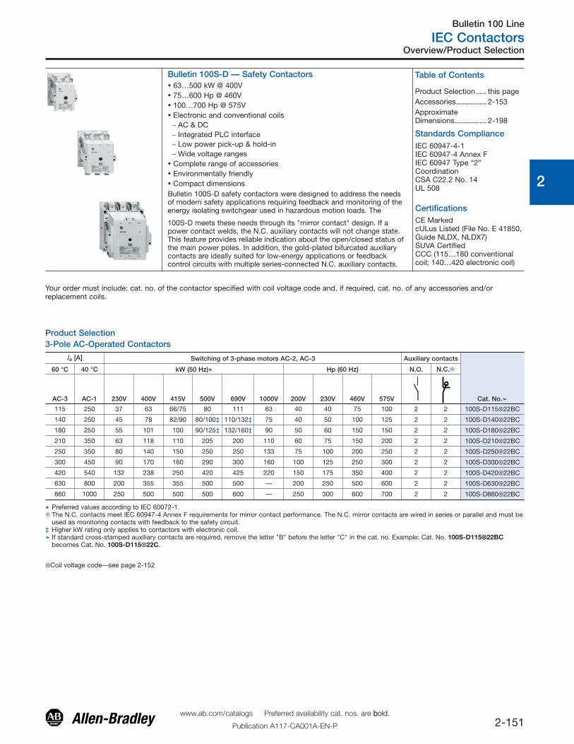
Bulletin 100S-D — Safety Contactors� 63…500 kW @ 400V� 75…600 Hp @ 460V� 100…700 Hp @ 575V� Electronic and conventional coils
− AC & DC− Integrated PLC interface− Low power pick-up & hold-in− Wide voltage ranges
� Complete range of accessories� Environmentally friendly� Compact dimensionsBulletin 100S-D safety contactors were designed to address the needsof modern safety applications requiring feedback and monitoring of theenergy isolating switchgear used in hazardous motion loads. The
100S-D meets these needs through its "mirror contact" design. If apower contact welds, the N.C. auxiliary contacts will not change state.This feature provides reliable indication about the open/closed status ofthe main power poles. In addition, the gold-plated bifurcated auxiliarycontacts are ideally suited for low-energy applications or feedbackcontrol circuits with multiple series-connected N.C. auxiliary contacts.
Your order must include: cat. no. of the contactor specified with coil voltage code and, if required, cat. no. of any accessories and/orreplacement coils.
Standards ComplianceIEC 60947-4-1IEC 60947-4 Annex FIEC 60947 Type “2”CoordinationCSA C22.2 No. 14UL 508
Certifications
Product Selection3-Pole AC-Operated Contactors
Ie [A] Switching of 3-phase motors AC-2, AC-3 Auxiliary contacts
Cat. No.�
60 °C 40 °C kW (50 Hz)� Hp (60 Hz) N.O. N.C.�
AC-3 AC-1 230V 400V 415V 500V 690V 1000V 200V 230V 460V 575V
115 250 37 63 66/75 80 111 63 40 40 75 100 2 2 100S-D115⊗22BC
140 250 45 78 82/90 80/100‡ 110/132‡ 75 40 50 100 125 2 2 100S-D140⊗22BC
180 250 55 101 100 90/125‡ 132/160‡ 90 50 60 150 150 2 2 100S-D180⊗22BC
210 350 63 118 110 205 200 110 60 75 150 200 2 2 100S-D210⊗22BC
250 350 80 140 150 250 250 133 75 100 200 250 2 2 100S-D250⊗22BC
300 450 90 170 160 290 300 160 100 125 250 300 2 2 100S-D300⊗22BC
420 540 132 238 250 420 425 220 150 175 350 400 2 2 100S-D420⊗22BC
630 800 200 355 355 500 500 — 200 250 500 600 2 2 100S-D630⊗22BC
860 1000 250 500 500 500 600 — 250 300 600 700 2 2 100S-D860⊗22BC
� Preferred values according to IEC 60072-1.� The N.C. contacts meet IEC 60947-4 Annex F requirements for mirror contact performance. The N.C. mirror contacts are wired in series or parallel and must be
used as monitoring contacts with feedback to the safety circuit.‡ Higher kW rating only applies to contactors with electronic coil.� If standard cross-stamped auxiliary contacts are required, remove the letter "B" before the letter "C" in the cat. no. Example: Cat. No. 100S-D115⊗⊗22BC
becomes Cat. No. 100S-D115⊗22C.
⊗Coil voltage code⎯see page 2-152
CE MarkedcULus Listed (File No. E 41850,Guide NLDX, NLDX7)SUVA CertifiedCCC (115…180 conventionalcoil; 140…420 electronic coil)
Table of Contents
Product Selection ...... this pageAccessories.................. 2-153ApproximateDimensions................... 2-198
Bulletin 100S-D
IEC Contactors
2-152www.ab.com/catalogs Preferred availability cat. nos. are bbold.
Publication A117-CA001A-EN-P
Product Selection
0
1
2
3
4
5
6
7
8
9
10
11
12
13
Conventional Coil [V] 24 48 100 110 120 200 208220
…230 230 240 277380
…400 415 440 480 500 550 600
100S-D115…100S-D180AC, 50 Hz K Y — D — — — A — T — N B G — M C —
AC, 60 Hz J X — — D — H — — A T — — N B — — C
100S-D115 AC, 50/60 Hz — — KP KN — KG — KL KF KA KT — — — — — — —
Electronic Coilw/ PLC Interface§ [V] 24 42…64 100
110…130 200
208…277
200…220
230…250 277
380…415
380…440
440…480
380…500 500
100S-D95…100S-D300AC,
50/60Hz
EJ♣ EY EP ED EG EA — — — ⎯ VN ⎯ EN ⎯
100S-D420AC,
50/60Hz
— — EP ED EG EA — — — ⎯ — ⎯ EN ⎯
100S-D630…100S-D860AC,
50/60Hz
— — EP ED EG — EG EA ET EN ⎯ EB — EM
Conventional Coil [V] 24
Ie [A] Switching of 3-phase motors AC-2, AC-3Auxiliarycontacts
Conventional CoilCat. No.
Electronic CoilCat. No.�
60 °C 40 °C kW (50 Hz) � Hp (60 Hz) N.O.N.C.� �
AC-3 AC-1 230V 400V 415V 500V 690V 1000V 200V 230V 460V 575V
115 250 37 63 66/75 80 111 63 40 40 75 100 2 2 100S-D115⊗33LC‡ 100S-D115⊗22BC
140 250 45 78 75 80/100§ 110/132§ 75 40 50 100 125 3 2/1L 100S-D140⊗33LC‡ 100S-D140⊗22BC
180 250 55 101 100 90/125§ 132/160§ 90 50 60 150 150 3 2/1L 100S-D180⊗33LC‡ 100S-D180⊗22BC
210 350 63 118 110 205 200 110 60 75 150 200 2 2 — 100S-D210⊗22BC
250 350 80 140 150 250 250 133 75 100 200 250 2 2 — 100S-D250⊗22BC
300 450 90 170 160 290 300 160 100 125 250 300 2 2 — 100S-D300⊗22BC
420 540 132 238 250 420 425 220 150 175 350 400 2 2 — 100S-D420⊗22BC
630 800 200 355 355 500 500 — 200 250 500 600 2 2 — 100S-D630⊗22BC
860 1000 250 500 500 500 600 — 250 300 600 700 2 2 — 100S-D860⊗22BC
� Preferred values according to IEC 60072-1.� The N.C. contacts meet IEC 60947-4 Annex F requirements for mirror contact performance. The N.C. mirror contacts are wired in series or parallel and must be
used as monitoring contacts with feedback to the safety circuit.‡ For conventional DC coil only. The pickup winding must be interconnected with the N.C. late-breaking auxiliary contacts.§ Higher kW rating only applies to contactors with electronic coil.� If standard cross-stamped front-mount auxiliary contacts are required, remove the letter "B" before the letter "C" in the Cat. No. Example: Cat. No. 100S-
D115⊗⊗22BC becomes Cat. No. 100S-D115⊗22C.
48 110 125 220 250100S-D115…100S-D180 DC ZJ ZY ZD ZS ZA ZT
♣Signal voltage of the cat. no. 100S-S… electronic interface Ue: 24V DC/Ie: 15 mAPick-up voltage: 13.0V DC…30.2V DCDrop-out voltage: -3.0V DC…+5.0V DC
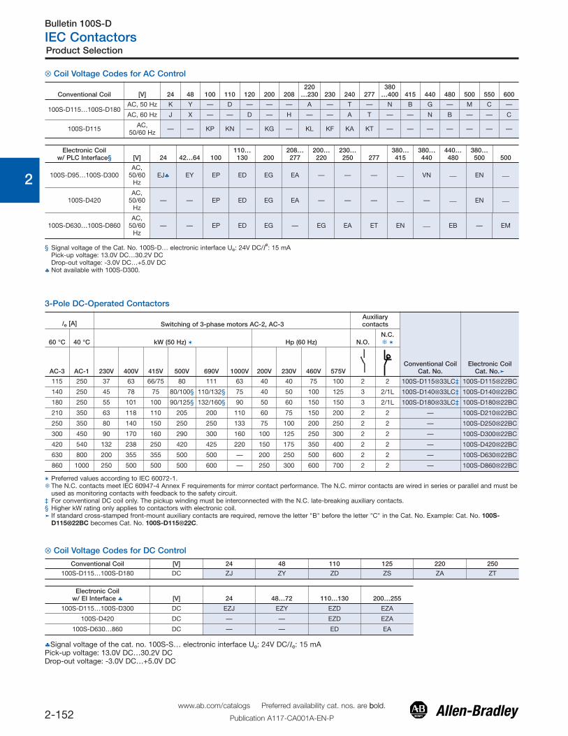
⊗ Coil Voltage Codes for DC Control
3-Pole DC-Operated Contactors
§ Signal voltage of the Cat. No. 100S-D… electronic interface Ue: 24V DC/Ie: 15 mAPick-up voltage: 13.0V DC…30.2V DCDrop-out voltage: -3.0V DC…+5.0V DC
♣ Not available with 100S-D300.
Electronic Coilw/ EI Interface ♣ [V] 24 48…72 110…130 200…255
100S-D115…100S-D300 DC EZJ EZY EZD EZA
100S-D420 DC — — EZD EZA
100S-D630…860 DC — — ED EA
⊗ Coil Voltage Codes for AC Control
Bulletin 100S-D
IEC Safety Contactors
2-198www.ab.com/catalogs Preferred availability cat. nos. are bbold.
Publication A117-CA001A-EN-P
0
1
2
3
4
5
6
7
8
9
10
11
12
13
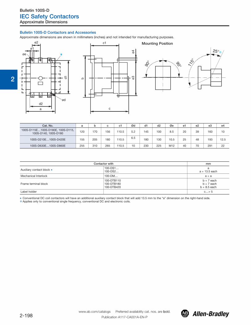
Bulletin 100S-D Contactors and AccessoriesApproximate dimensions are shown in millimeters (inches) and not intended for manufacturing purposes.
d2
a c
e1
e2 c1
øe
bd1 e3e4
ød
Mounting Position
90°90°
115°
25°�
Cat. No. a b c c1 Ød d1 d2 Øe e1 e2 e3 e4
100S-D115E…100S-D180E, 100S-D115,100S-D140, 100S-D180 120 170 156 110.5 5.2 145 100 8.5 20 39 160 10
100S-D210E…100S-D420E 155 205 180 110.5 6.5 180 130 10.5 25 48 193 12.5
100S-D630E…100S-D860E 255 310 265 110.5 10 230 225 M12 40 70 291 22
Contactor with mm
Auxiliary contact block � 100-DS1…100-DS2…
aa + 13.5 each
Mechanical Interlock 100-DM… a + a
Frame terminal block100-DTB110100-DTB180100-DTB420
b + 7 eachb + 7 each
b + 8.5 each
Label holder c…+ 5
� Conventional DC coil contactors will have an additional auxiliary contact block that will add 13.5 mm to the “a” dimension on the right-hand side.�Applies only to conventional single frequency, conventional DC and electronic coils.
Approximate Dimensions
Bulletin 100/104-K, 100/104-C, 100/104-D, 100S/104S-C, 100S-D
IEC Contactors
2-158www.ab.com/catalogs Preferred availability cat. nos. are bbold.
Publication A117-CA001A-EN-P
Specifications
0
1
2
3
4
5
6
7
8
9
10
11
12
13
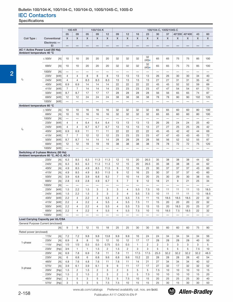
100-KR 100/104-K 100/104-C, 100S/104S-C
05 09 05 09 12 09 12 16 23 30 37 40*200 40*400 43 60
Coil Type : Conventional X X X X X X X X X X X X X X X
Electronic —EI — — — — — — — — — — — — — — —
AC-1 Active Power Load (50 Hz);Ambient temperature 40 °C
Ie
≤ 500V [A] 10 10 20 20 20 32 32 32 32(40)� 65 65 75 75 85 100
690V [A] 10 10 20 20 20 32 32 32 32(40)� 65 65 75 75 85 100
1000V [A] — — — — — — — — — — — — — — —
230V [kW] 4 4 8 8 8 13 13 13 13 26 26 30 30 34 40
240V [kW] 4 4 8.3 8.3 8.3 13 13 13 13 27 27 31 31 35 42
400V [kW] 6.9 6.9 14 14 14 22 22 22 22 45 45 52 52 59 69
415V [kW] 7 7 14 14 14 23 23 23 23 47 47 54 54 61 72
500V [kW] 8.7 8.7 17 17 17 28 28 28 28 56 56 65 65 74 87
690V [kW] 12 12 24 24 24 38 38 38 38 78 78 90 90 102 120
1000V [kW] — — — — — — — — — — — — — — —
Ambient temperature 60 °C
Ie
≤ 500V [A] 10 10 16 16 16 32 32 32 32 65 65 60 60 80 100
690V [A] 10 10 16 16 16 32 32 32 32 65 65 60 60 80 100
1000V [A] — — — — — — — — — — — — — — —
230V [kW] 4 4 6.4 6.4 6.4 13 13 13 13 26 26 24 24 25 40
240V [kW] 4 4 6.7 6.7 6.7 13 13 13 13 27 27 25 25 26 42
400V [kW] 6.9 6.9 11 11 11 22 22 22 22 45 45 42 42 44 69
415V [kW] 7 7 12 12 12 23 23 23 23 47 47 43 43 45 72
500V [kW] 8.7 8.7 14 14 14 28 28 28 28 56 56 52 52 55 87
690V [kW] 12 12 19 19 19 38 38 38 38 78 78 72 72 75 120
1000V [kW] — — — — — — — — — — — — — — —
Switching of 3-phase Motors; (50 Hz)Ambient temperature 60 °C, AC-2, AC-3
230V [A] 6.3 8.5 6.3 11.3 11.3 12 15 20 26.5 35 38 38 38 44 62
240V [A] 6.3 8.5 6.3 11.3 11.3 12 15 20 26.5 35 38 38 38 44 62
400V [A] 4.9 8.5 4.9 8.5 11.5 9 12 16 23 30 37 37 37 43 60
415V [A] 4.9 8.5 4.9 8.5 11.5 9 12 16 23 30 37 37 37 43 60
500V [A] 3.9 6.8 3.9 6.8 9.2 7 10 14 20 25 30 29 30 38 55
690V [A] 2.8 4.9 2.8 4.9 6.7 5 7 9 12 18 21 9 21 25 34
1000V [A] — — — — — — — — — — — — — — —
230V [kW] 1.5 2.2 1.5 3 3 3 4 5.5 7.5 10 11 11 11 13 18.5
240V [kW] 1.5 2.2 1.5 3 3 3 4 5.5 7.5 10 11 11 11 13 18.5
400V [kW] 2.2 4 2.2 4 5.5 4 5.5 7.5 11 15 18.5 18.5 18.5 22 32
415V [kW] 2.2 4 2.2 4 5.5 4 5.5 7.5 11 15 20 20 20 22 32
500V [kW] 2.2 4 2.2 4 5.5 4 5.5 7.5 13 15 20 18.5 20 25 37
690V [kW] 2.2 4 2.2 4 5.5 4 5.5 7.5 10 15 18.5 7.5 18.5 22 32
1000V [kW] — — — — — — — — — — — — — — —
Load Carrying Capacity per UL/CSA
General Purpose Current (enclosed)
[A] 9 9 12 15 18 25 25 30 30 55 60 60 60 75 90
Rated power (enclosed)
1-phase
115V [A] 7.2 7.2 9.8 9.8 13.8 9.8 9.8 16 24 24 34 34 34 34 56
230V [A] 6.9 8 8 10 12 10 12 17 17 28 28 28 28 40 50
115V [Hp] 1/3 1/3 0.5 0.5 0.75 0.5 0.5 1 2 2 3 3 3 3 5
230V [Hp] 3/4 1 1 1.5 2 1.5 2 3 3 5 5 5 5 7.5 10
3-phase
200V [A] 6.9 7.8 6.9 7.8 11 7.8 11 17.5 17.5 25.3 32.2 32.2 32.2 32.2 48.3
230V [A] 6 6.8 6 6.8 9.6 6.8 9.6 15.2 22 28 28 28 28 42 54
460V [A] 4.8 7.6 4.8 7.6 11 7.6 11 14 21 27 34 34 34 40 52
575V [A] 3.9 6.1 3.9 6.1 9 9 11 17 17 27 32 17 32 32 52
200V [Hp] 1.5 2 1.5 2 3 2 3 5 5 7.5 10 10 10 10 15
230V [Hp] 1.5 2 1.5 2 3 2 3 5 7.5 10 10 10 10 15 20
460V [Hp] 3 5 3 5 7.5 5 7.5 10 15 20 25 25 25 30 40
575V [Hp] 3 5 3 5 7.5 7.5 10 15 15 25 30 15 30 30 50
Bulletin 100/104-K, 100/104-C, 100/104-D, 100S/104S-C, 100S-D
IEC Contactors
2-159www.ab.com/catalogs Preferred availability cat. nos. are bbold.
Publication A117-CA001A-EN-P
Specifications
0
1
2
3
4
5
6
7
8
9
10
11
12
13
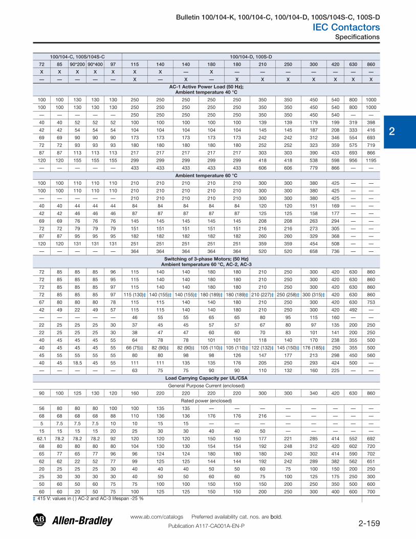
100/104-C, 100S/104S-C 100/104-D, 100S-D
72 85 90*200 90*400 97 115 140 140 180 180 210 250 300 420 630 860
X X X X X X X — X — — — — — — —
— — — — — X — X — X X X X X X X
AC-1 Active Power Load (50 Hz);Ambient temperature 40 °C
100 100 130 130 130 250 250 250 250 250 350 350 450 540 800 1000
100 100 130 130 130 250 250 250 250 250 350 350 450 540 800 1000
— — — — — 250 250 250 250 250 350 350 450 540 — —
40 40 52 52 52 100 100 100 100 100 139 139 179 199 319 398
42 42 54 54 54 104 104 104 104 104 145 145 187 208 333 416
69 69 90 90 90 173 173 173 173 173 242 242 312 346 554 693
72 72 93 93 93 180 180 180 180 180 252 252 323 359 575 719
87 87 113 113 113 217 217 217 217 217 303 303 390 433 693 866
120 120 155 155 155 299 299 299 299 299 418 418 538 598 956 1195
— — — — — 433 433 433 433 433 606 606 779 866 — —
Ambient temperature 60 °C
100 100 110 110 110 210 210 210 210 210 300 300 380 425 — —
100 100 110 110 110 210 210 210 210 210 300 300 380 425 — —
— — — — — 210 210 210 210 210 300 300 380 425 — —
40 40 44 44 44 84 84 84 84 84 120 120 151 169 — —
42 42 46 46 46 87 87 87 87 87 125 125 158 177 — —
69 69 76 76 76 145 145 145 145 145 208 208 263 294 — —
72 72 79 79 79 151 151 151 151 151 216 216 273 305 — —
87 87 95 95 95 182 182 182 182 182 260 260 329 368 — —
120 120 131 131 131 251 251 251 251 251 359 359 454 508 — —
— — — — — 364 364 364 364 364 520 520 658 736 — —
Switching of 3-phase Motors; (50 Hz)Ambient temperature 60 °C, AC-2, AC-3
72 85 85 85 96 115 140 140 180 180 210 250 300 420 630 860
72 85 85 85 95 115 140 140 180 180 210 250 300 420 630 860
72 85 85 85 97 115 140 140 180 180 210 250 300 420 630 860
72 85 85 85 97 115 (130)‡ 140 (155)‡ 140 (155)‡ 180 (189)‡ 180 (189)‡ 210 (227)‡ 250 (258)‡ 300 (315)‡ 420 630 860
67 80 80 80 78 115 115 140 140 180 210 250 300 420 630 753
42 49 22 49 57 115 115 140 140 180 210 250 300 420 492 —
— — — — — 46 55 55 65 65 80 95 115 160 — —
22 25 25 25 30 37 45 45 57 57 67 80 97 135 200 250
22 25 25 25 30 38 47 47 60 60 70 83 101 141 200 250
40 45 45 45 55 64 78 78 101 101 118 140 170 238 355 500
40 45 45 45 55 66 (75)‡ 82 (90)‡ 82 (90)‡ 105 (110)‡ 105 (110)‡ 122 (132)‡ 145 (150)‡ 176 (185)‡ 250 355 500
45 55 55 55 55 80 80 98 98 126 147 177 213 298 450 560
40 45 18.5 45 55 111 111 135 135 176 205 250 293 424 500 —
— — — — — 63 75 75 90 90 110 132 160 225 — —
Load Carrying Capacity per UL/CSA
General Purpose Current (enclosed)
90 100 125 130 120 160 220 220 220 220 300 300 340 420 630 860
Rated power (enclosed)
56 80 80 80 100 100 135 135 — — — — — — — —
68 68 68 68 88 110 136 136 176 176 216 — — — — —
5 7.5 7.5 7.5 10 10 15 15 — — — — — — — —
15 15 15 15 20 25 30 30 40 40 50 — — — — —
62.1 78.2 78.2 78.2 92 120 120 120 150 150 177 221 285 414 552 692
68 80 80 80 80 104 130 130 154 154 192 248 312 420 602 720
65 77 65 77 96 96 124 124 180 180 180 240 302 414 590 702
62 62 22 52 77 99 125 125 144 144 192 242 289 382 562 651
20 25 25 25 30 40 40 40 50 50 60 75 100 150 200 250
25 30 30 30 30 40 50 50 60 60 75 100 125 175 250 300
50 60 50 60 75 75 100 100 150 150 150 200 250 350 500 600
60 60 20 50 75 100 125 125 150 150 200 250 300 400 600 700‡ 415 V: values in ( ) AC-2 and AC-3 lifespan -25 %
Bulletin 100/104-K, 100/104-C, 100/104-D, 100S/104S-C, 100S-D
IEC Contactors
2-160www.ab.com/catalogs Preferred availability cat. nos. are bbold.
Publication A117-CA001A-EN-P
Specifications
0
1
2
3
4
5
6
7
8
9
10
11
12
13
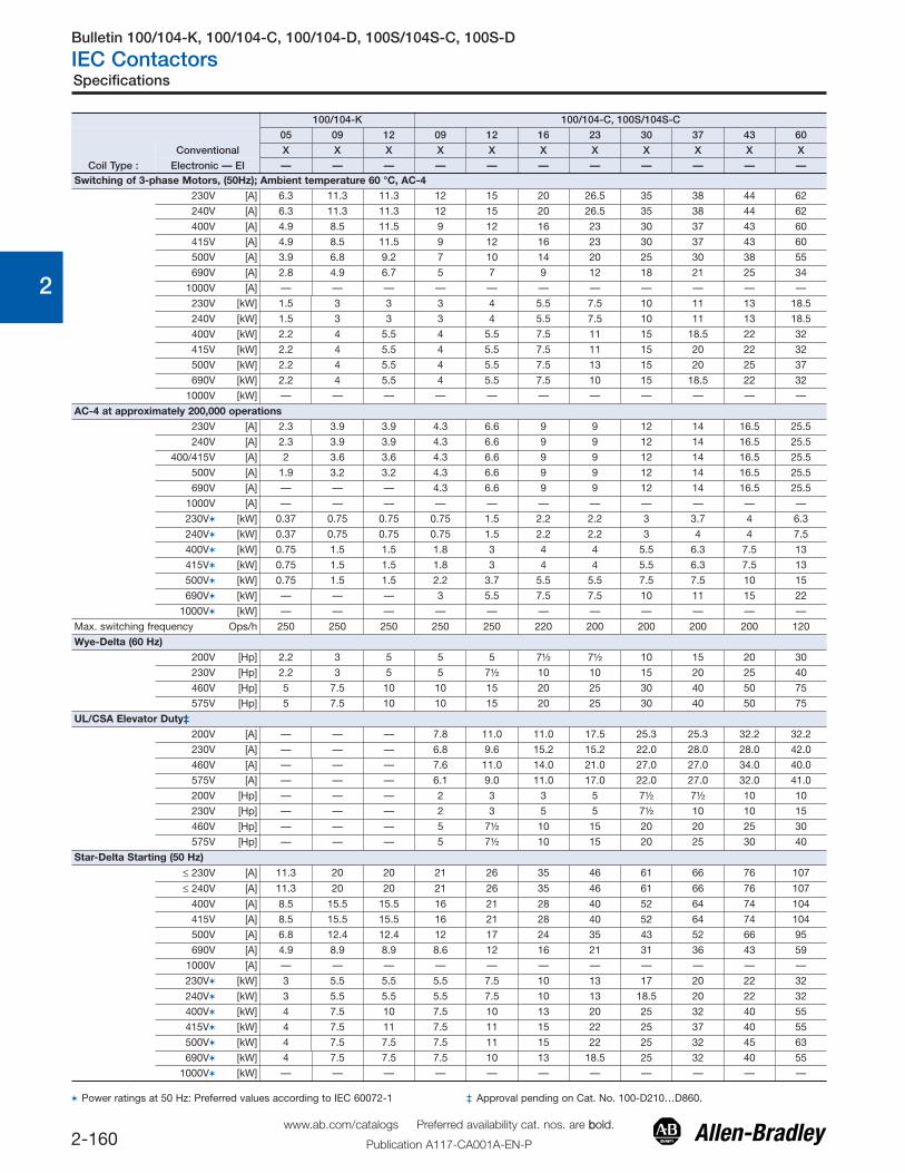
100/104-K 100/104-C, 100S/104S-C
05 09 12 09 12 16 23 30 37 43 60
Coil Type :
Conventional X X X X X X X X X X X
Electronic — EI — — — — — — — — — — —Switching of 3-phase Motors, (50Hz); Ambient temperature 60 °C, AC-4
230V [A] 6.3 11.3 11.3 12 15 20 26.5 35 38 44 62
240V [A] 6.3 11.3 11.3 12 15 20 26.5 35 38 44 62
400V [A] 4.9 8.5 11.5 9 12 16 23 30 37 43 60
415V [A] 4.9 8.5 11.5 9 12 16 23 30 37 43 60
500V [A] 3.9 6.8 9.2 7 10 14 20 25 30 38 55
690V [A] 2.8 4.9 6.7 5 7 9 12 18 21 25 34
1000V [A] — — — — — — — — — — —
230V [kW] 1.5 3 3 3 4 5.5 7.5 10 11 13 18.5
240V [kW] 1.5 3 3 3 4 5.5 7.5 10 11 13 18.5
400V [kW] 2.2 4 5.5 4 5.5 7.5 11 15 18.5 22 32
415V [kW] 2.2 4 5.5 4 5.5 7.5 11 15 20 22 32
500V [kW] 2.2 4 5.5 4 5.5 7.5 13 15 20 25 37
690V [kW] 2.2 4 5.5 4 5.5 7.5 10 15 18.5 22 32
1000V [kW] — — — — — — — — — — —
AC-4 at approximately 200,000 operations230V [A] 2.3 3.9 3.9 4.3 6.6 9 9 12 14 16.5 25.5
240V [A] 2.3 3.9 3.9 4.3 6.6 9 9 12 14 16.5 25.5
400/415V [A] 2 3.6 3.6 4.3 6.6 9 9 12 14 16.5 25.5
500V [A] 1.9 3.2 3.2 4.3 6.6 9 9 12 14 16.5 25.5
690V [A] — — — 4.3 6.6 9 9 12 14 16.5 25.5
1000V [A] — — — — — — — — — — —
230V� [kW] 0.37 0.75 0.75 0.75 1.5 2.2 2.2 3 3.7 4 6.3
240V� [kW] 0.37 0.75 0.75 0.75 1.5 2.2 2.2 3 4 4 7.5
400V� [kW] 0.75 1.5 1.5 1.8 3 4 4 5.5 6.3 7.5 13
415V� [kW] 0.75 1.5 1.5 1.8 3 4 4 5.5 6.3 7.5 13
500V� [kW] 0.75 1.5 1.5 2.2 3.7 5.5 5.5 7.5 7.5 10 15
690V� [kW] — — — 3 5.5 7.5 7.5 10 11 15 22
1000V� [kW] — — — — — — — — — — —
Max. switching frequency Ops/h 250 250 250 250 250 220 200 200 200 200 120
Wye-Delta (60 Hz)200V [Hp] 2.2 3 5 5 5 7½ 7½ 10 15 20 30
230V [Hp] 2.2 3 5 5 7½ 10 10 15 20 25 40
460V [Hp] 5 7.5 10 10 15 20 25 30 40 50 75
575V [Hp] 5 7.5 10 10 15 20 25 30 40 50 75
UL/CSA Elevator Duty‡200V [A] — — — 7.8 11.0 11.0 17.5 25.3 25.3 32.2 32.2
230V [A] — — — 6.8 9.6 15.2 15.2 22.0 28.0 28.0 42.0
460V [A] — — — 7.6 11.0 14.0 21.0 27.0 27.0 34.0 40.0
575V [A] — — — 6.1 9.0 11.0 17.0 22.0 27.0 32.0 41.0
200V [Hp] — — — 2 3 3 5 7½ 7½ 10 10
230V [Hp] — — — 2 3 5 5 7½ 10 10 15
460V [Hp] — — — 5 7½ 10 15 20 20 25 30
575V [Hp] — — — 5 7½ 10 15 20 25 30 40
Star-Delta Starting (50 Hz)
≤ 230V [A] 11.3 20 20 21 26 35 46 61 66 76 107
≤ 240V [A] 11.3 20 20 21 26 35 46 61 66 76 107
400V [A] 8.5 15.5 15.5 16 21 28 40 52 64 74 104
415V [A] 8.5 15.5 15.5 16 21 28 40 52 64 74 104
500V [A] 6.8 12.4 12.4 12 17 24 35 43 52 66 95
690V [A] 4.9 8.9 8.9 8.6 12 16 21 31 36 43 59
1000V [A] — — — — — — — — — — —
230V� [kW] 3 5.5 5.5 5.5 7.5 10 13 17 20 22 32
240V� [kW] 3 5.5 5.5 5.5 7.5 10 13 18.5 20 22 32
400V� [kW] 4 7.5 10 7.5 10 13 20 25 32 40 55
415V� [kW] 4 7.5 11 7.5 11 15 22 25 37 40 55
500V� [kW] 4 7.5 7.5 7.5 11 15 22 25 32 45 63
690V� [kW] 4 7.5 7.5 7.5 10 13 18.5 25 32 40 55
1000V� [kW] — — — — — — — — — — —
� Power ratings at 50 Hz: Preferred values according to IEC 60072-1 ‡ Approval pending on Cat. No. 100-D210…D860.
Bulletin 100/104-K, 100/104-C, 100/104-D, 100S/104S-C, 100S-D
IEC Contactors
2-161www.ab.com/catalogs Preferred availability cat. nos. are bbold.
Publication A117-CA001A-EN-P
Specifications
0
1
2
3
4
5
6
7
8
9
10
11
12
13
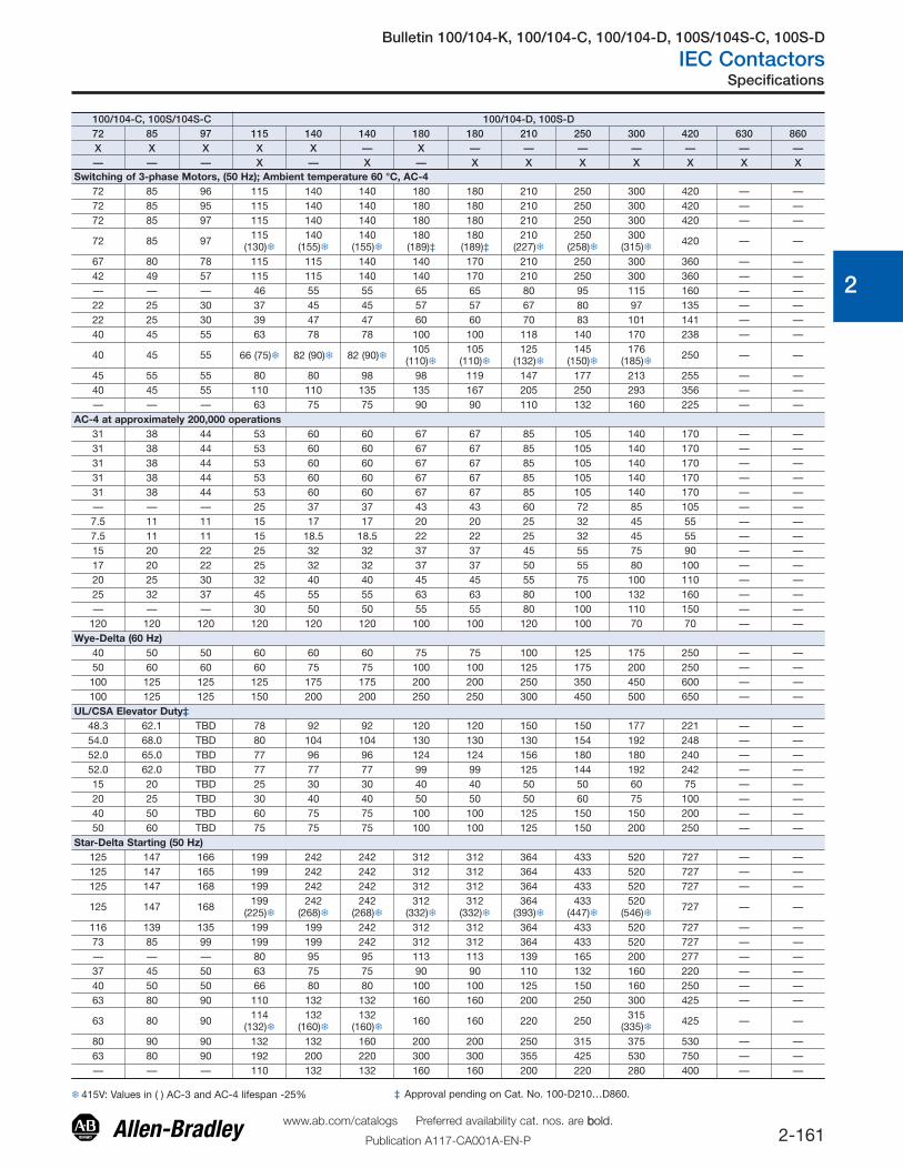
100/104-C, 100S/104S-C 100/104-D, 100S-D72 85 97 115 140 140 180 180 210 250 300 420 630 860X X X X X — X — — — — — — —— — — X — X — X X X X X X X
Switching of 3-phase Motors, (50 Hz); Ambient temperature 60 °C, AC-472 85 96 115 140 140 180 180 210 250 300 420 — —72 85 95 115 140 140 180 180 210 250 300 420 — —72 85 97 115 140 140 180 180 210 250 300 420 — —
72 85 97 115(130)�
140(155)�
140(155)�
180(189)‡
180(189)‡
210(227)�
250(258)�
300(315)� 420 — —
67 80 78 115 115 140 140 170 210 250 300 360 — —42 49 57 115 115 140 140 170 210 250 300 360 — —— — — 46 55 55 65 65 80 95 115 160 — —22 25 30 37 45 45 57 57 67 80 97 135 — —22 25 30 39 47 47 60 60 70 83 101 141 — —40 45 55 63 78 78 100 100 118 140 170 238 — —
40 45 55 66 (75)� 82 (90)� 82 (90)�105
(110)�105
(110)�125
(132)�145
(150)�176
(185)� 250 — —
45 55 55 80 80 98 98 119 147 177 213 255 — —40 45 55 110 110 135 135 167 205 250 293 356 — —— — — 63 75 75 90 90 110 132 160 225 — —
AC-4 at approximately 200,000 operations31 38 44 53 60 60 67 67 85 105 140 170 — —31 38 44 53 60 60 67 67 85 105 140 170 — —31 38 44 53 60 60 67 67 85 105 140 170 — —31 38 44 53 60 60 67 67 85 105 140 170 — —31 38 44 53 60 60 67 67 85 105 140 170 — —— — — 25 37 37 43 43 60 72 85 105 — —7.5 11 11 15 17 17 20 20 25 32 45 55 — —7.5 11 11 15 18.5 18.5 22 22 25 32 45 55 — —15 20 22 25 32 32 37 37 45 55 75 90 — —17 20 22 25 32 32 37 37 50 55 80 100 — —20 25 30 32 40 40 45 45 55 75 100 110 — —25 32 37 45 55 55 63 63 80 100 132 160 — —— — — 30 50 50 55 55 80 100 110 150 — —
120 120 120 120 120 120 100 100 120 100 70 70 — —Wye-Delta (60 Hz)
40 50 50 60 60 60 75 75 100 125 175 250 — —50 60 60 60 75 75 100 100 125 175 200 250 — —100 125 125 125 175 175 200 200 250 350 450 600 — —100 125 125 150 200 200 250 250 300 450 500 650 — —
UL/CSA Elevator Duty‡48.3 62.1 TBD 78 92 92 120 120 150 150 177 221 — —54.0 68.0 TBD 80 104 104 130 130 130 154 192 248 — —52.0 65.0 TBD 77 96 96 124 124 156 180 180 240 — —52.0 62.0 TBD 77 77 77 99 99 125 144 192 242 — —15 20 TBD 25 30 30 40 40 50 50 60 75 — —20 25 TBD 30 40 40 50 50 50 60 75 100 — —40 50 TBD 60 75 75 100 100 125 150 150 200 — —50 60 TBD 75 75 75 100 100 125 150 200 250 — —
Star-Delta Starting (50 Hz)125 147 166 199 242 242 312 312 364 433 520 727 — —125 147 165 199 242 242 312 312 364 433 520 727 — —125 147 168 199 242 242 312 312 364 433 520 727 — —
125 147 168 199(225)�
242(268)�
242(268)�
312(332)�
312(332)�
364(393)�
433(447)�
520(546)� 727 — —
116 139 135 199 199 242 312 312 364 433 520 727 — —73 85 99 199 199 242 312 312 364 433 520 727 — —— — — 80 95 95 113 113 139 165 200 277 — —37 45 50 63 75 75 90 90 110 132 160 220 — —40 50 50 66 80 80 100 100 125 150 160 250 — —63 80 90 110 132 132 160 160 200 250 300 425 — —
63 80 90 114(132)�
132(160)�
132(160)� 160 160 220 250 315
(335)� 425 — —
80 90 90 132 132 160 200 200 250 315 375 530 — —63 80 90 192 200 220 300 300 355 425 530 750 — —— — — 110 132 132 160 160 200 220 280 400 — —
� 415V: Values in ( ) AC-3 and AC-4 lifespan -25% ‡ Approval pending on Cat. No. 100-D210…D860.
Bulletin 100/104-K, 100/104-C, 100/104-D, 100S/104S-C, 100S-D
IEC Contactors
2-162www.ab.com/catalogs Preferred availability cat. nos. are bbold.
Publication A117-CA001A-EN-P
Specifications
0
1
2
3
4
5
6
7
8
9
10
11
12
13
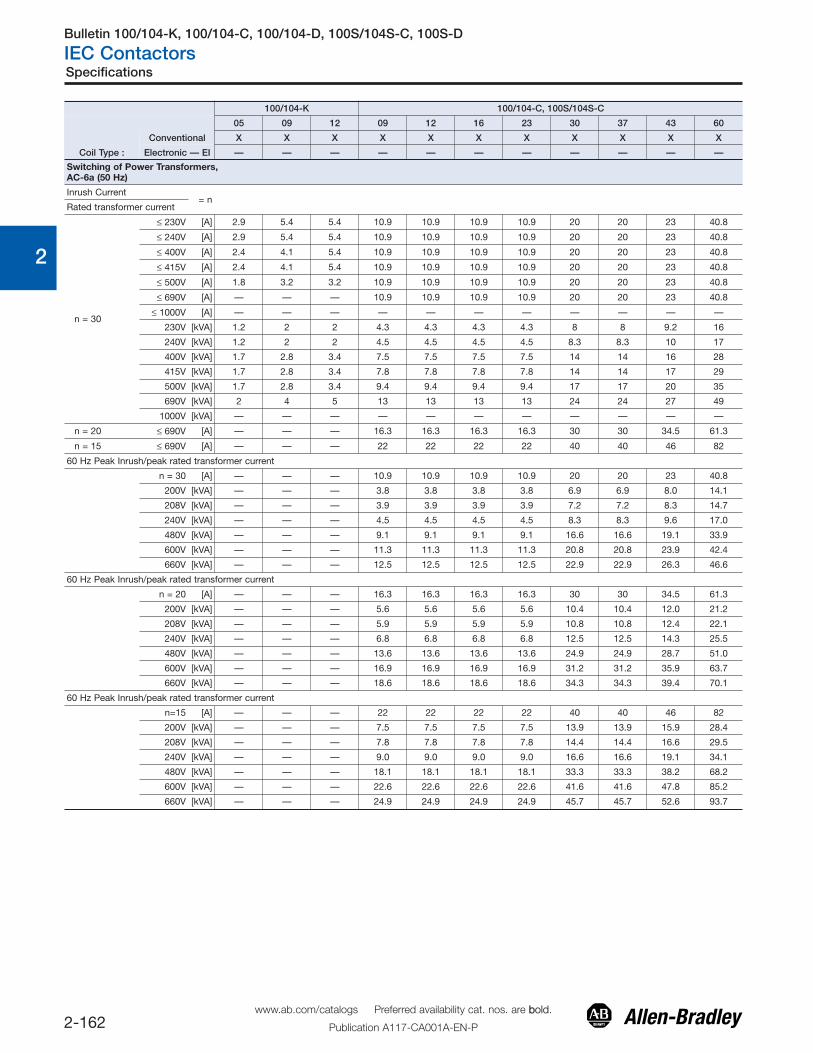
100/104-K 100/104-C, 100S/104S-C
05 09 12 09 12 16 23 30 37 43 60
Coil Type :
Conventional X X X X X X X X X X X
Electronic — EI — — — — — — — — — — —
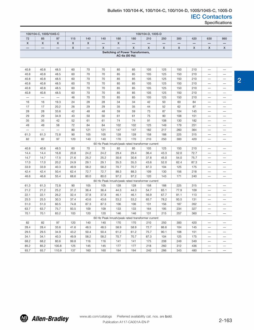
Switching of Power Transformers,AC-6a (50 Hz)
Inrush Current= n
Rated transformer current
n = 30
≤ 230V [A] 2.9 5.4 5.4 10.9 10.9 10.9 10.9 20 20 23 40.8
≤ 240V [A] 2.9 5.4 5.4 10.9 10.9 10.9 10.9 20 20 23 40.8
≤ 400V [A] 2.4 4.1 5.4 10.9 10.9 10.9 10.9 20 20 23 40.8
≤ 415V [A] 2.4 4.1 5.4 10.9 10.9 10.9 10.9 20 20 23 40.8
≤ 500V [A] 1.8 3.2 3.2 10.9 10.9 10.9 10.9 20 20 23 40.8
≤ 690V [A] — — — 10.9 10.9 10.9 10.9 20 20 23 40.8
≤ 1000V [A] — — — — — — — — — — —
230V [kVA] 1.2 2 2 4.3 4.3 4.3 4.3 8 8 9.2 16
240V [kVA] 1.2 2 2 4.5 4.5 4.5 4.5 8.3 8.3 10 17
400V [kVA] 1.7 2.8 3.4 7.5 7.5 7.5 7.5 14 14 16 28
415V [kVA] 1.7 2.8 3.4 7.8 7.8 7.8 7.8 14 14 17 29
500V [kVA] 1.7 2.8 3.4 9.4 9.4 9.4 9.4 17 17 20 35
690V [kVA] 2 4 5 13 13 13 13 24 24 27 49
1000V [kVA] — — — — — — — — — — —
n = 20 ≤ 690V [A] — — — 16.3 16.3 16.3 16.3 30 30 34.5 61.3
n = 15 ≤ 690V [A] — — — 22 22 22 22 40 40 46 82
60 Hz Peak Inrush/peak rated transformer current
n = 30 [A] — — — 10.9 10.9 10.9 10.9 20 20 23 40.8
200V [kVA] — — — 3.8 3.8 3.8 3.8 6.9 6.9 8.0 14.1
208V [kVA] — — — 3.9 3.9 3.9 3.9 7.2 7.2 8.3 14.7
240V [kVA] — — — 4.5 4.5 4.5 4.5 8.3 8.3 9.6 17.0
480V [kVA] — — — 9.1 9.1 9.1 9.1 16.6 16.6 19.1 33.9
600V [kVA] — — — 11.3 11.3 11.3 11.3 20.8 20.8 23.9 42.4
660V [kVA] — — — 12.5 12.5 12.5 12.5 22.9 22.9 26.3 46.6
60 Hz Peak Inrush/peak rated transformer current
n = 20 [A] — — — 16.3 16.3 16.3 16.3 30 30 34.5 61.3
200V [kVA] — — — 5.6 5.6 5.6 5.6 10.4 10.4 12.0 21.2
208V [kVA] — — — 5.9 5.9 5.9 5.9 10.8 10.8 12.4 22.1
240V [kVA] — — — 6.8 6.8 6.8 6.8 12.5 12.5 14.3 25.5
480V [kVA] — — — 13.6 13.6 13.6 13.6 24.9 24.9 28.7 51.0
600V [kVA] — — — 16.9 16.9 16.9 16.9 31.2 31.2 35.9 63.7
660V [kVA] — — — 18.6 18.6 18.6 18.6 34.3 34.3 39.4 70.1
60 Hz Peak Inrush/peak rated transformer current
n=15 [A] — — — 22 22 22 22 40 40 46 82
200V [kVA] — — — 7.5 7.5 7.5 7.5 13.9 13.9 15.9 28.4
208V [kVA] — — — 7.8 7.8 7.8 7.8 14.4 14.4 16.6 29.5
240V [kVA] — — — 9.0 9.0 9.0 9.0 16.6 16.6 19.1 34.1
480V [kVA] — — — 18.1 18.1 18.1 18.1 33.3 33.3 38.2 68.2
600V [kVA] — — — 22.6 22.6 22.6 22.6 41.6 41.6 47.8 85.2
660V [kVA] — — — 24.9 24.9 24.9 24.9 45.7 45.7 52.6 93.7
Bulletin 100/104-K, 100/104-C, 100/104-D, 100S/104S-C, 100S-D
IEC Contactors
2-163www.ab.com/catalogs Preferred availability cat. nos. are bbold.
Publication A117-CA001A-EN-P
Specifications
0
1
2
3
4
5
6
7
8
9
10
11
12
13
100/104-C, 100S/104S-C 100/104-D, 100S-D
72 85 97 115 140 140 180 180 210 250 300 420 630 860
X X X X X — X — — — — — — —
— — — X — X — X X X X X X X
Switching of Power Transformers,AC-6a (50 Hz)
40.8 40.8 48.5 60 70 70 85 85 105 125 150 210 — —
40.8 40.8 48.5 60 70 70 85 85 105 125 150 210 — —
40.8 40.8 48.5 60 70 70 85 85 105 125 150 210 — —
40.8 40.8 48.5 60 70 70 85 85 105 125 150 210 — —
40.8 40.8 48.5 60 70 70 85 85 105 125 150 210 — —
40.8 40.8 48.5 60 70 70 85 85 105 125 150 210 — —
— — — 46 70 70 85 85 105 125 150 210 — —
16 16 19.3 24 28 28 34 34 42 50 60 84 — —
17 17 20.2 26 29 29 35 35 44 52 62 87 — —
28 28 33.6 42 48 48 59 59 73 87 104 145 — —
29 29 34.9 43 50 50 61 61 75 90 108 151 — —
35 35 42 52 61 61 74 74 91 108 130 182 — —
49 49 58 72 84 84 102 102 125 149 179 251 — —
— — — 80 121 121 147 147 182 217 260 364 — —
61.3 61.3 72.8 90 105 105 128 128 158 188 225 315 — —
82 82 97 120 140 140 170 170 210 250 300 420 — —
60 Hz Peak Inrush/peak rated transformer current
40.8 40.8 48.5 60 70 70 85 85 105 125 150 210 — —
14.4 14.4 16.8 20.8 24.2 24.2 29.4 29.4 36.4 43.3 52.0 72.7 — —
14.7 14.7 17.5 21.6 25.2 25.2 30.6 30.6 37.8 45.0 54.0 75.7 — —
17.0 17.0 20.2 24.9 29.1 29.1 35.3 35.3 43.6 52.0 62.4 87.3 — —
33.9 33.9 40.3 49.9 58.2 58.2 70.7 70.7 87.3 104 125 175 — —
42.4 42.4 50.4 62.4 72.7 72.7 88.3 88.3 109 130 156 218 — —
46.6 46.6 55.4 68.6 80.0 80.0 97.2 97.2 120 143 171 240 — —
60 Hz Peak Inrush/peak rated transformer current
61.3 61.3 72.8 90 105 105 128 128 158 188 225 315 — —
21.2 21.2 25.2 31.2 36.4 36.4 44.3 44.3 54.7 65.1 77.9 109 — —
22.1 22.1 26.2 32.4 37.8 37.8 46.1 46.1 56.9 67.7 81.1 113 — —
25.5 25.5 30.3 37.4 43.6 43.6 53.2 53.2 65.7 78.2 93.5 131 — —
51.0 51.0 60.5 74.8 87.3 87.3 106 106 131 156 187 262 — —
63.7 63.7 75.7 93.5 109 109 133 133 164 195 234 327 — —
70.1 70.1 83.2 103 120 120 146 146 131 215 257 360 — —
60 Hz Peak Inrush/peak rated transformer current
82 82 97 120 140 140 170 170 210 250 300 420 — —
28.4 28.4 33.6 41.6 48.5 48.5 58.9 58.9 72.7 86.6 104 145 — —
29.5 29.5 34.9 43.2 50.4 50.4 61.2 61.2 75.7 90.1 108 151 — —
34.1 34.1 40.3 49.9 58.2 58.2 70.7 70.7 87.3 104 125 175 — —
68.2 68.2 80.6 99.8 116 116 141 141 175 208 249 349 — —
85.2 85.2 100.8 125 145 145 177 177 218 260 312 436 — —
93.7 93.7 110.9 137 160 160 194 194 240 286 343 480 — —
Bulletin 100/104-K, 100/104-C, 100/104-D, 100S/104S-C, 100S-D
IEC Contactors
2-164www.ab.com/catalogs Preferred availability cat. nos. are bbold.
Publication A117-CA001A-EN-P
Specifications
0
1
2
3
4
5
6
7
8
9
10
11
12
13
100/104-K 100/104-C, 100S/104S-C
05 09 12 09 12 16 23 30 37 40*200 40*400 43 60
Coil Type :
Conventional X X X X X X X X X X X X X
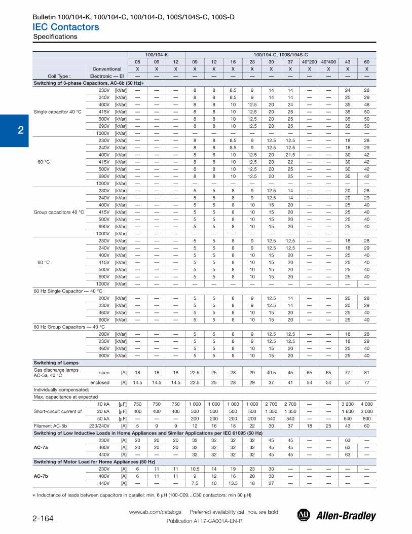
Electronic — EI — — — — — — — — — — — — —Switching of 3-phase Capacitors, AC-6b (50 Hz)�
Single capacitor 40 °C
230V [kVar] — — — 8 8 8.5 9 14 14 — — 24 28
240V [kVar] — — — 8 8 8.5 9 14 14 — — 25 29
400V [kVar] — — — 8 8 10 12.5 20 24 — — 35 48
415V [kVar] — — — 8 8 10 12.5 20 25 — — 35 50
500V [kVar] — — — 8 8 10 12.5 20 25 — — 35 50
690V [kVar] — — — 8 8 10 12.5 20 25 — — 35 50
1000V [kVar] — — — — — — — — — — — — —
60 °C
230V [kVar] — — — 8 8 8.5 9 12.5 12.5 — — 18 28
240V [kVar] — — — 8 8 8.5 9 12.5 12.5 — — 18 29
400V [kVar] — — — 8 8 10 12.5 20 21.5 — — 30 42
415V [kVar] — — — 8 8 10 12.5 20 22 — — 30 42
500V [kVar] — — — 8 8 10 12.5 20 25 — — 30 42
690V [kVar] — — — 8 8 10 12.5 20 25 — — 30 42
1000V [kVar] — — — — — — — — — — — — —
Group capacitors 40 °C
230V [kVar] — — — 5 5 8 9 12.5 14 — — 20 28
240V [kVar] — — — 5 5 8 9 12.5 14 — — 20 29
400V [kVar] — — — 5 5 8 10 15 20 — — 25 40
415V [kVar] — — — 5 5 8 10 15 20 — — 25 40
500V [kVar] — — — 5 5 8 10 15 20 — — 25 40
690V [kVar] — — — 5 5 8 10 15 20 — — 25 40
1000V [kVar] — — — — — — — — — — — — —
60 °C
230V [kVar] — — — 5 5 8 9 12.5 12.5 — — 18 28
240V [kVar] — — — 5 5 8 9 12.5 12.5 — — 18 29
400V [kVar] — — — 5 5 8 10 15 20 — — 25 40
415V [kVar] — — — 5 5 8 10 15 20 — — 25 40
500V [kVar] — — — 5 5 8 10 15 20 — — 25 40
690V [kVar] — — — 5 5 8 10 15 20 — — 25 40
1000V [kVar] — — — — — — — — — — — — —
60 Hz Single Capacitor — 40 °C
200V [kVar] — — — 5 5 8 9 12.5 14 — — 20 28
230V [kVar] — — — 5 5 8 9 12.5 14 — — 20 29
460V [kVar] — — — 5 5 8 10 15 20 — — 25 40
600V [kVar] — — — 5 5 8 10 15 20 — — 25 40
60 Hz Group Capacitors — 40 °C
200V [kVar] — — — 5 5 8 9 12.5 12.5 — — 18 28
230V [kVar] — — — 5 5 8 9 12.5 12.5 — — 18 29
460V [kVar] — — — 5 5 8 10 15 20 — — 25 40
600V [kVar] — — — 5 5 8 10 15 20 — — 25 40
Switching of Lamps
Gas discharge lampsAC-5a, 40 °C open [A] 18 18 18 22.5 25 28 29 40.5 45 65 65 77 81
enclosed [A] 14.5 14.5 14.5 22.5 25 28 29 37 41 54 54 57 77
Individually compensated:
Max. capacitance at expected
Short-circuit current of
10 kA [μF] 750 750 750 1 000 1 000 1 000 1 000 2 700 2 700 — — 3 200 4 000
20 kA [μF] 400 400 400 500 500 500 500 1 350 1 350 — — 1 600 2 000
50 kA [μF] — — — 200 200 200 200 540 540 — — 640 800
Filament AC-5b 230/240V [A] 5 9 9 12 16 18 22 30 37 18 25 43 60
Switching of Low Inductive Loads in Home Appliances and Similar Applications per IEC 61095 (50 Hz)
AC-7a
230V [A] 20 20 20 32 32 32 32 45 45 — — 63 —
400V [A] 20 20 20 32 32 32 32 45 45 — — 63 —
440V [A] — — — 32 32 32 32 45 45 — — 63 —
Switching of Motor Load for Home Appliances (50 Hz)
AC-7b
230V [A] 6 11 11 10.5 14 19 23 30 — — — — —
400V [A] 6 11 11 9 12 16 20 30 — — — — —
440V [A] — — — 7.5 10 13.5 18 27 — — — — —
� Inductance of leads between capacitors in parallel: min. 6 μH (100-C09…C30 contactors: min 30 μH)
Bulletin 100/104-K, 100/104-C, 100/104-D, 100S/104S-C, 100S-D
IEC Contactors
2-165www.ab.com/catalogs Preferred availability cat. nos. are bbold.
Publication A117-CA001A-EN-P
Specifications
0
1
2
3
4
5
6
7
8
9
10
11
12
13
100/104-C, 100S/104S-C 100/104-D, 100S-D
72 85 90*200 90*400 97 115 140 140 180 180 210 250 300 420 630 860
X X X X X X X — X — — — — — — —
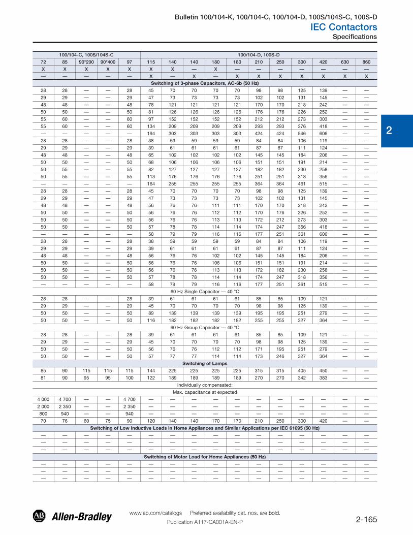
— — — — — X — X — X X X X X X XSwitching of 3-phase Capacitors, AC-6b (50 Hz)
28 28 — — 28 45 70 70 70 70 98 98 125 139 — —
29 29 — — 29 47 73 73 73 73 102 102 131 145 — —
48 48 — — 48 78 121 121 121 121 170 170 218 242 — —
50 50 — — 50 81 126 126 126 126 176 176 226 252 — —
55 60 — — 60 97 152 152 152 152 212 212 273 303 — —
55 60 — — 60 134 209 209 209 209 293 293 376 418 — —
— — — — — 194 303 303 303 303 424 424 546 606 — —
28 28 — — 28 38 59 59 59 59 84 84 106 119 — —
29 29 — — 29 39 61 61 61 61 87 87 111 124 — —
48 48 — — 48 65 102 102 102 102 145 145 184 206 — —
50 50 — — 50 68 106 106 106 106 151 151 191 214 — —
50 55 — — 55 82 127 127 127 127 182 182 230 258 — —
50 55 — — 55 113 176 176 176 176 251 251 318 356 — —
— — — — — 164 255 255 255 255 364 364 461 515 — —
28 28 — — 28 45 70 70 70 70 98 98 125 139 — —
29 29 — — 29 47 73 73 73 73 102 102 131 145 — —
48 48 — — 48 56 76 76 111 111 170 170 218 242 — —
50 50 — — 50 56 76 76 112 112 170 176 226 252 — —
50 50 — — 50 56 76 76 113 113 172 212 273 303 — —
50 50 — — 50 57 78 78 114 114 174 247 356 418 — —
— — — — — 58 79 79 116 116 177 251 361 606 — —
28 28 — — 28 38 59 59 59 59 84 84 106 119 — —
29 29 — — 29 39 61 61 61 61 87 87 111 124 — —
48 48 — — 48 56 76 76 102 102 145 145 184 206 — —
50 50 — — 50 56 76 76 106 106 151 151 191 214 — —
50 50 — — 50 56 76 76 113 113 172 182 230 258 — —
50 50 — — 50 57 78 78 114 114 174 247 318 356 — —
— — — — — 58 79 79 116 116 177 251 361 515 — —
60 Hz Single Capacitor — 40 °C
28 28 — — 28 39 61 61 61 61 85 85 109 121 — —
29 29 — — 29 45 70 70 70 70 98 98 125 139 — —
50 50 — — 50 89 139 139 139 139 195 195 251 279 — —
50 50 — — 50 116 182 182 182 182 255 255 327 364 — —
60 Hz Group Capacitor — 40 °C
28 28 — — 28 39 61 61 61 61 85 85 109 121 — —
29 29 — — 29 45 70 70 70 70 98 98 125 139 — —
50 50 — — 50 56 76 76 112 112 171 195 251 279 — —
50 50 — — 50 57 77 77 114 114 173 246 327 364 — —
Switching of Lamps
85 90 115 115 115 144 225 225 225 225 315 315 405 450 — —
81 90 95 95 100 122 189 189 189 189 270 270 342 383 — —
Individually compensated:
Max. capacitance at expected
4 000 4 700 — — 4 700 — — — — — — — — — — —
2 000 2 350 — — 2 350 — — — — — — — — — — —
800 940 — — 940 — — — — — — — — — — —
70 76 60 75 90 120 140 140 170 170 210 250 300 420 — —
Switching of Low Inductive Loads in Home Appliances and Similar Applications per IEC 61095 (50 Hz)
— — — — — — — — — — — — — — — —
— — — — — — — — — — — — — — — —
— — — — — — — — — — — — — — — —
Switching of Motor Load for Home Appliances (50 Hz)
— — — — — — — — — — — — — — — —
— — — — — — — — — — — — — — — —
— — — — — — — — — — — — — — — —
Bulletin 100/104-K, 100/104-C, 100/104-D, 100S/104S-C, 100S-D
IEC Contactors
2-166www.ab.com/catalogs Preferred availability cat. nos. are bbold.
Publication A117-CA001A-EN-P
Specifications
0
1
2
3
4
5
6
7
8
9
10
11
12
13
100/104-K 100/104-C, 100S/104S-C05 09 12 09 12 16 23 30 37 40*200 40*400 43 60
Coil Type :Conventional X X X X X X X X X X X X X
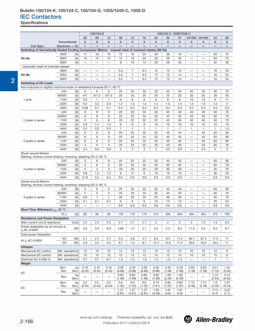
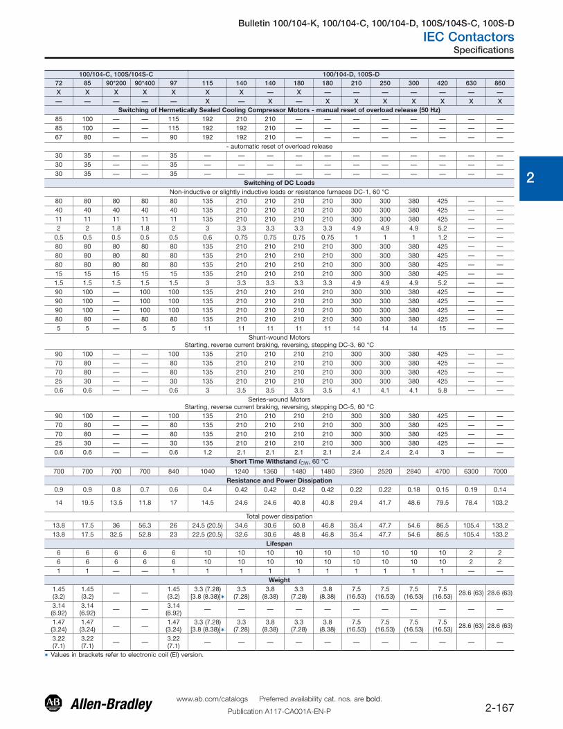
Electronic — EI — — — — — — — — — — — — —Switching of Hermetically Sealed Cooling Compressor Motors - manual reset of overload release (50 Hz)
AC-8a400V [A] 11 18 18 12 16 22 32 38 45 — — 63 72500V [A] 10 15 15 12 16 22 32 38 45 — — 63 72690V [A] — — — 8 10 14 20 28 35 — — 42 56
- automatic reset of overload release
AC-8b400V [A] — — — 5.5 7 9.3 12 13 14 — — 16 24500V [A] — — — 5.5 7 9.3 12 13 14 — — 16 24690V [A] — — — 5.5 7 9.3 12 13 14 — — 16 24
Switching of DC LoadsNon-inductive or slightly inductive loads or resistance furnaces DC-1, 60 °C
1 pole
24V [A] 6 9 9 25 25 32 32 45 45 45 45 50 7048/60V [A] 4/1 6/1.5 6/1.5 20 20 20 20 25 25 25 25 30 40
110V [A] 0.6 1 1 6 6 6 6 8 8 10 10 9 11220V [A] 0.2 0.3 0.3 1.5 1.5 1.5 1.5 1.5 1.5 1.5 1.5 1.5 2440V [A] 0.08 0.1 0.1 0.4 0.4 0.4 0.4 0.4 0.4 0.4 0.4 0.5 0.5
2 poles in series
24V [A] 6 9 9 25 25 32 32 45 45 45 45 50 7048/60V [A] 6 8 8 25 25 32 32 45 45 45 45 50 70
110V [A] 4 6 6 25 25 32 32 45 45 45 45 50 70220V [A] 0.8 1.2 1.2 8 8 8 10 10 10 10 10 10 15440V [A] 0.2 0.3 0.3 1 1 1 1 1 1 1 1 1 1.5
3 poles in series
24V [A] 6 9 9 25 25 32 32 45 45 — 45 63 9048/60V [A] 6 9 9 25 25 32 32 45 45 — 45 63 90
110V [A] 6 9 9 25 25 32 32 45 45 — 45 63 90220V [A] 3 4 4 25 25 32 32 45 45 — 45 50 70440V [A] 0.4 0.6 0.6 3 3 3 3 3.5 3.5 — 3.5 4 5
Shunt-wound MotorsStarting, reverse current braking, reversing, stepping DC-3, 60 °C
3 poles in series
24V [A] 5 9 9 25 25 32 32 45 45 — — 63 9048/60V [A] 4 6 6 25 25 32 32 45 45 — — 50 70
110V [A] 2 3 3 20 20 25 25 30 30 — — 35 70220V [A] 0.8 1.2 1.2 6 6 6 10 15 15 — — 20 25440V [A] 0.15 0.2 0.2 0.6 0.6 0.6 0.6 0.6 0.6 — — 0.6 0.6
Series-wound MotorsStarting, reverse current braking, reversing, stepping DC-5, 60 °C
3 poles in series
24V [A] 5 9 9 25 25 32 32 45 45 — — 63 9048/60V [A] 2 3 3 25 25 32 32 45 45 — — 50 70
110V [A] 0.6 1 1 20 20 25 25 30 30 — — 35 70220V [A] 0.1 0.1 0.1 6 6 6 10 15 15 — — 20 25440V [A] — — — 0.6 0.6 0.6 0.6 0.6 0.6 — — 0.6 0.6
Short Time Withstand ICW, 60 °C
10 s [A] 60 96 96 170 170 170 215 300 304 304 304 375 700Resistance and Power DissipationMain current circuit resistance [mΩ] 2.2 2.2 2.2 2.7 2.7 2.7 2 2 2 2 1.5 1.5 0.9Power dissipation by all circuits atIe AC-3/400V [W] 0.3 0.9 0.9 0.66 1.2 2.1 3.2 5.4 8.2 11.3 8.4 8.3 9.7
Total power dissipation
At Ie AC-3/400VAC [W] 2.1 2.7 2.7 3.3 3.8 4.7 6.2 8.4 11.2 26.1 37.4 11.5 11DC [W] 2.9 3.5 3.5 6.7 7.2 8.1 12.4 14.6 17.4 32.6 43.9 18.4 11
LifespanMechanical AC control [Mil. operations] 15 15 15 13 13 13 13 13 13 10 10 12 6Mechanical DC control [Mil. operations] 15 15 15 13 13 13 13 13 13 10 10 13 6Electrical AC-3 (400 V) [Mil. operations] 0.7 0.7 0.7 1.3 1.3 1.3 1.3 1.3 1.3 — — 1 1Weight
AC
Non-Rev.
kg(lbs.)
0.16(0.35)
0.16(0.35)
0.16(0.35)
0.39(0.86)
0.39(0.86)
0.39(0.86)
0.39(0.86)
0.48(1.06)
0.49(1.08)
0.63(1.39)
0.63(1.39)
0.51(1.12)
1.45(3.20)
Rev. kg(lbs.) — — — 0.85
(1.89)0.85(1.89)
0.85(1.89)
0.85(1.89)
1.08(2.39)
1.08(2.39) — — 1.15
(2.54)3.14(6.92)
DC
Non-Rev.
kg(lbs.)
0.2(0.44)
0.2(0.44)
0.2(0.44)
0.6(1.32)
0.6(1.32)
0.6(1.32)
0.73(1.61)
0.85(1.87)
0.85(1.87)
1.12(2.46)
1.12(2.46)
1.0(2.20)
1.47(3.24)
Rev. kg(lbs.) — — — 1.27
(2.81)1.27(2.81)
1.27(2.81)
1.53(3.39)
1.81(4.0)
1.81(4.0) — — 2.13
(4.7)3.22(7.1)
Bulletin 100/104-K, 100/104-C, 100/104-D, 100S/104S-C, 100S-D
IEC Contactors
2-167www.ab.com/catalogs Preferred availability cat. nos. are bbold.
Publication A117-CA001A-EN-P
Specifications
0
1
2
3
4
5
6
7
8
9
10
11
12
13
100/104-C, 100S/104S-C 100/104-D, 100S-D72 85 90*200 90*400 97 115 140 140 180 180 210 250 300 420 630 860X X X X X X X — X — — — — — — —— — — — — X — X — X X X X X X X
Switching of Hermetically Sealed Cooling Compressor Motors - manual reset of overload release (50 Hz)85 100 — — 115 192 210 210 — — — — — — — —85 100 — — 115 192 192 210 — — — — — — — —67 80 — — 90 192 192 210 — — — — — — — —
- automatic reset of overload release30 35 — — 35 — — — — — — — — — — —30 35 — — 35 — — — — — — — — — — —30 35 — — 35 — — — — — — — — — — —
Switching of DC LoadsNon-inductive or slightly inductive loads or resistance furnaces DC-1, 60 °C
80 80 80 80 80 135 210 210 210 210 300 300 380 425 — —40 40 40 40 40 135 210 210 210 210 300 300 380 425 — —11 11 11 11 11 135 210 210 210 210 300 300 380 425 — —2 2 1.8 1.8 2 3 3.3 3.3 3.3 3.3 4.9 4.9 4.9 5.2 — —
0.5 0.5 0.5 0.5 0.5 0.6 0.75 0.75 0.75 0.75 1 1 1 1.2 — —80 80 80 80 80 135 210 210 210 210 300 300 380 425 — —80 80 80 80 80 135 210 210 210 210 300 300 380 425 — —80 80 80 80 80 135 210 210 210 210 300 300 380 425 — —15 15 15 15 15 135 210 210 210 210 300 300 380 425 — —1.5 1.5 1.5 1.5 1.5 3 3.3 3.3 3.3 3.3 4.9 4.9 4.9 5.2 — —90 100 — 100 100 135 210 210 210 210 300 300 380 425 — —90 100 — 100 100 135 210 210 210 210 300 300 380 425 — —90 100 — 100 100 135 210 210 210 210 300 300 380 425 — —80 80 — 80 80 135 210 210 210 210 300 300 380 425 — —5 5 — 5 5 11 11 11 11 11 14 14 14 15 — —
Shunt-wound MotorsStarting, reverse current braking, reversing, stepping DC-3, 60 °C
90 100 — — 100 135 210 210 210 210 300 300 380 425 — —70 80 — — 80 135 210 210 210 210 300 300 380 425 — —70 80 — — 80 135 210 210 210 210 300 300 380 425 — —25 30 — — 30 135 210 210 210 210 300 300 380 425 — —0.6 0.6 — — 0.6 3 3.5 3.5 3.5 3.5 4.1 4.1 4.1 5.8 — —
Series-wound MotorsStarting, reverse current braking, reversing, stepping DC-5, 60 °C
90 100 — — 100 135 210 210 210 210 300 300 380 425 — —70 80 — — 80 135 210 210 210 210 300 300 380 425 — —70 80 — — 80 135 210 210 210 210 300 300 380 425 — —25 30 — — 30 135 210 210 210 210 300 300 380 425 — —0.6 0.6 — — 0.6 1.2 2.1 2.1 2.1 2.1 2.4 2.4 2.4 3 — —
Short Time Withstand ICW, 60 °C
700 700 700 700 840 1040 1240 1360 1480 1480 2360 2520 2840 4700 6300 7000Resistance and Power Dissipation
0.9 0.9 0.8 0.7 0.6 0.4 0.42 0.42 0.42 0.42 0.22 0.22 0.18 0.15 0.19 0.14
14 19.5 13.5 11.8 17 14.5 24.6 24.6 40.8 40.8 29.4 41.7 48.6 79.5 78.4 103.2
Total power dissipation13.8 17.5 36 56.3 26 24.5 (20.5) 34.6 30.6 50.8 46.8 35.4 47.7 54.6 86.5 105.4 133.213.8 17.5 32.5 52.8 23 22.5 (20.5) 32.6 30.6 48.8 46.8 35.4 47.7 54.6 86.5 105.4 133.2
Lifespan6 6 6 6 6 10 10 10 10 10 10 10 10 10 2 26 6 6 6 6 10 10 10 10 10 10 10 10 10 2 21 1 — — 1 1 1 1 1 1 1 1 1 1 — —
Weight1.45(3.2)
1.45(3.2) — — 1.45
(3.2)3.3 (7.28)
[3.8 (8.38)]�3.3
(7.28)3.8
(8.38)3.3
(7.28)3.8
(8.38)7.5
(16.53)7.5
(16.53)7.5
(16.53)7.5
(16.53) 28.6 (63) 28.6 (63)
3.14(6.92)
3.14(6.92) — — 3.14
(6.92) — — — — — — — — — — —
1.47(3.24)
1.47(3.24) — — 1.47
(3.24)3.3 (7.28)
[3.8 (8.38)]�3.3
(7.28)3.8
(8.38)3.3
(7.28)3.8
(8.38)7.5
(16.53)7.5
(16.53)7.5
(16.53)7.5
(16.53) 28.6 (63) 28.6 (63)
3.22(7.1)
3.22(7.1) — — 3.22
(7.1) — — — — — — — — — — —
� Values in brackets refer to electronic coil (EI) version.

Bulletin 100/104-K, 100/104-C, 100/104-D, 100S/104S-C, 100S-D
IEC Contactors
2-168www.ab.com/catalogs Preferred availability cat. nos. are bbold.
Publication A117-CA001A-EN-P
Specifications
0
1
2
3
4
5
6
7
8
9
10
11
12
13
100-KR 100/104-K 100/104-C, 100S/104S-C
05 09 05 09 12 09 12 16 23 30 37 40 43 60 72 85 97
Coil Type : Conventional X X X X X X X X X X X X X X X X X
Electr. — EI — — — — — — — — — — — — — — — — —
Conductor Cross Sections - Main ContactsTerminal type � � � ‡
(1) conductor [mm2] 0.50…2.5 0.75…2.5 1…4 2.5…10 2.5…16 2.5…35 2.5…35
(2) conductors [mm2] 0.50…2.5 0.75…2.5 1…4 2.5…10 2.5…10 2.5…25 2.5…35
(1) conductor [mm2] 0.75…2.5§ 1…4 1.5…6 2.5…16 2.5…25 2.5…50 2.5…50
(2) conductors [mm2] 0.75…2.5§ 1…2.5+ 1…4 1.5…6 2.5…16 2.5…16 2.5…35 2.5…50
b max. [mm] — — — — — —
c max. [mm] — — — — — —
s max. [mm] — — — — — —
Ø min. [mm] — — — — — —
Recommended torque [N•m] — 1.2 1.5…2.0 2.5…3.5 2.5…3.5 4.5…6
Cross section per UL/CSA [AWG] 18…14§ 18…12 16…10 14…6 14…6 14…4 14…1
Recommended torque [lb-in] — 10.6 13.3…17.7 22…31 22…31 40…53
With terminal lug kit — — — — — — —
Cross section per UL/CSA [AWG] — — — — — — —
Recommended torque [lb-in] — — — — — — —
With Frame Terminal Block — — — — — — —
top opening [mm2] — — — — — — —
bottom opening [mm2] — — — — — — —
top opening [mm2] — — — — — — —
bott. opening [mm2] — — — — — — —
b max.s top
s bottom[mm2] — — — — — — —
Recommended torque [N•m] — — — — — — —
Cross section per UL/CSAtop [AWG] — — — — — — —
bottom [AWG] — — — — — — —
Recommended torque [lb-in] — — — — — — —
� Pozidriv No. 2 / Blade No. 3 screw�Pozidriv No. 2 / Blade No. 4 screw‡ Hexagonal socket screw§ Fine- or coarse-stranded only

Bulletin 100/104-K, 100/104-C, 100/104-D, 100S/104S-C, 100S-D
IEC Contactors
2-169www.ab.com/catalogs Preferred availability cat. nos. are bbold.
Publication A117-CA001A-EN-P
Specifications
0
1
2
3
4
5
6
7
8
9
10
11
12
13
100/104-D, 100S-D
115 140 180 210 250 300 420 630 860
X X X — — — — — —
X X X X X X X X X
— — — —
— — — —
— — — —
— — — —
25 30 52 52
12.5 15 22 22
5 6 2 x 8 2 x 8
8.3 10.5 13 13
22 43 68 68
— — — —
195 380 600 600
100-DL180‡ 100-DL420‡ 100-DL630 100-DL860
6…300 MCM (2x) 4…350 MCM (2X) 2/0…500MCM (4X) 2/0…500MCM
88…106 375 400 400
100-DTB180‡ 100-DTB420� — —
16…35 25…185♣ — —
16…95 25…185 — —
16…50 25…240 — —
16…120 25…240 — —
203…93…14
256…206…20
— —
14 25 — —
6…1 / 0 AWG 4 AWG…600 MCM — —
6 AWG…250 MCM 4 AWG…600 MCM — —
124 220 — —
� Pozidriv No. 2 / Blade No. 3 screw�Pozidriv No. 2 / Blade No. 4 screw‡ Hexagonal socket screw§ Hexagonal screw

Bulletin 100/104-K, 100/104-C, 100/104-D, 100S/104S-C, 100S-D
IEC Contactors
2-170www.ab.com/catalogs Preferred availability cat. nos. are bbold.
Publication A117-CA001A-EN-P
Specifications
0
1
2
3
4
5
6
7
8
9
10
11
12
13
Short-Circuit Coordination Data‡
100/104-K 100/104-C, 100S/104S-C
05 09 12 09 12 16 23 30 37 40*200 40*400 43 60 72 85 90*200 90*400 97
Coil Type :
Conventional X X X X X X X X X X X X X X X X X X
Electronic – El — — — — — — — — — — — — — — — — — —
Short Circuit Coordination (Max. Fuse or Circuit Breaker Rating)
Per IEC 60947-4-1 (contactor and fuses only)
DIN Fuses - gG, gL 50 kA Available Fault Current
Type "1" (690V) [A] 35 35 35 50 50 50 80 125 125 160 160 160 250 250 250 250 250 250
Type "2" (400V) [A] 16 20 20 25 35 35 40 80 80 63 80 100 160 160 160 160 100 200
Type "2" (690V) [A] — — — 25 35 35 40 80 80 63 80 100 160 160 160 160 100 200
BS88 Fuses 65 kA Available Fault Current
Type "1" (415V) [A] — — — 25 32 40 50 63 80 — — 80 100 160 160 — — TBD
Type "2" (415V) [A] — — — 20 25 32 50 63 80 — — 80 100 125 160 — — TBD
Per UL 508 and CSA 22.2 No. 14(contactor and fuses or circuit breaker only)
UL Class K5 and RK5 Fuses 5 kA Available Fault Current
UL Listed Combination (600V) [A] 40 40 40 35 40 70 90 110 125 125 125 150 200 — — — — —
UL Class K5 and RK5 Fuses 10 kA Available Fault Current
UL Listed Combination (600V) [A] — — — — — — — — — — — — — 250 300 300 300 350
UL Class L Fuses 18 kA Available Fault Current
UL Listed Combination (600V) [A] — — — — — — — — — — — — — — — — — —
UL Class L Fuses 30 kA Available Fault Current
UL Listed Combination (600V) [A] — — — — — — — — — — — — — — — — — —
UL Class L Fuses 42 kA Available Fault Current
UL Listed Combination (600V) [A] — — — — — — — — — — — — — — — — — —
UL Class CC and CSA HRCI-MISC Fuses 50 kA Available Fault Current
UL Listed Combination (600V) [A] 30 30 30 — — — — — — — — — — — — — — —
UL Class J and CSA HRCI-J Fuses 50 kA Available Fault Current
UL Listed Combination (600V) [A] 30 30 30 — — — — — — — — — — — — — — —
UL Class CC and CSA HRCI-MISC Fuses 100 kA Available Fault Current
UL verified combination toIEC 60947-4-1 "Type 2" [A] — — — 20§ 20 30 40 — — — — — — — — — — —
UL Class J and CSA HRCI-J Fuses 100 kA Available Fault Current
UL verified combination toIEC 60947-4-1 "Type 2" [A] — — — 20§ 20 30 40 50 50 — — 70 80 100 150 — — TBD
UL Inverse-Time Circuit Breaker 5 kA Available Fault Current
UL Listed Combination (480V) [A] — — — 30 30 50 50 125 125 — — 125 250 — — — — —
UL Listed Combination (600V) [A] — — — — — — — 125 125 — — 125 250 — — — — —
UL Inverse-Time Circuit Breaker 10 kA Available Fault Current
UL Listed Combination (600V) [A] — — — — — — — — — — — — — 250 250 — — 250
UL Inverse-Time Circuit Breaker 18 kA Available Fault Current
UL Listed Combination (600V) [A] — — — — — — — — — — — — — — — — — —
UL Inverse-Time Circuit Breaker 30 kA Available Fault Current
UL Listed Combination (600V) [A] — — — — — — — 50 50 — — 50 110 110 110 — — TBD
UL Inverse-Time Circuit Breaker 42 kA Available Fault Current
UL Listed Combination (600V) [A] — — — — — — — — — — — — — — — — — —
UL Inverse-Time Circuit Breaker 50 kA Available Fault Current
UL Listed Combination (480V) [A] — — — — — — — 50 50 — — 50 — — — — — —
UL Inverse-Time Circuit Breaker 65 kA Available Fault Current
UL Listed Combination (480V) [A] — — — — — — — — — — — — 110 110 110 — — TBD
§ 15 A max. fuse for Type 2 coordination.‡ See www.ab.com/certifications/ul508a for complete short-circuit current ratings.
Bulletin 100/104-K, 100/104-C, 100/104-D, 100S/104S-C, 100S-D
IEC Contactors
2-171www.ab.com/catalogs Preferred availability cat. nos. are bbold.
Publication A117-CA001A-EN-P
Specifications
0
1
2
3
4
5
6
7
8
9
10
11
12
13
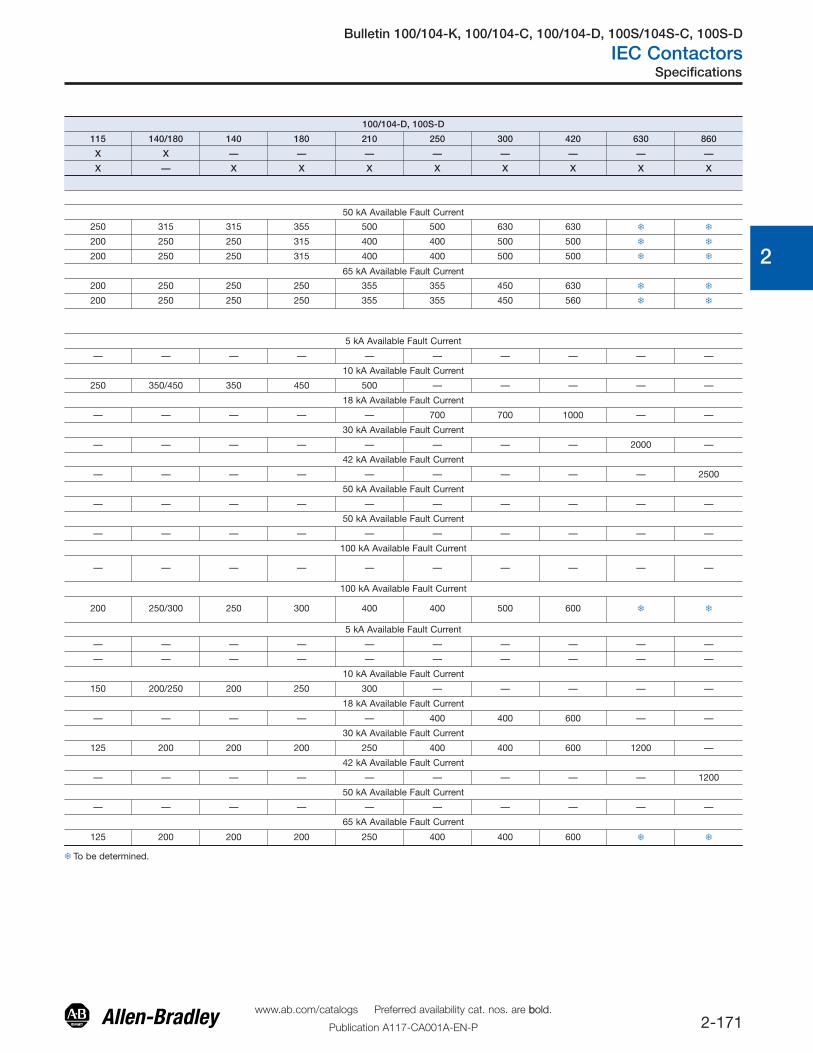
100/104-D, 100S-D
115 140/180 140 180 210 250 300 420 630 860
X X — — — — — — — —
X — X X X X X X X X
50 kA Available Fault Current
250 315 315 355 500 500 630 630 � �
200 250 250 315 400 400 500 500 � �
200 250 250 315 400 400 500 500 � �
65 kA Available Fault Current
200 250 250 250 355 355 450 630 � �
200 250 250 250 355 355 450 560 � �
5 kA Available Fault Current
— — — — — — — — — —
10 kA Available Fault Current
250 350/450 350 450 500 — — — — —
18 kA Available Fault Current
— — — — — 700 700 1000 — —
30 kA Available Fault Current
— — — — — — — — 2000 —
42 kA Available Fault Current
— — — — — — — — — 2500
50 kA Available Fault Current
— — — — — — — — — —
50 kA Available Fault Current
— — — — — — — — — —
100 kA Available Fault Current
— — — — — — — — — —
100 kA Available Fault Current
200 250/300 250 300 400 400 500 600 � �
5 kA Available Fault Current
— — — — — — — — — —
— — — — — — — — — —
10 kA Available Fault Current
150 200/250 200 250 300 — — — — —
18 kA Available Fault Current
— — — — — 400 400 600 — —
30 kA Available Fault Current
125 200 200 200 250 400 400 600 1200 —
42 kA Available Fault Current
— — — — — — — — — 1200
50 kA Available Fault Current
— — — — — — — — — —
65 kA Available Fault Current
125 200 200 200 250 400 400 600 � �
� To be determined.
Bulletin 100/104-K, 100/104-C, 100/104-D, 100S/104S-C, 100S-D
IEC Contactors
2-172www.ab.com/catalogs Preferred availability cat. nos. are bbold.
Publication A117-CA001A-EN-P
Specifications
0
1
2
3
4
5
6
7
8
9
10
11
12
13
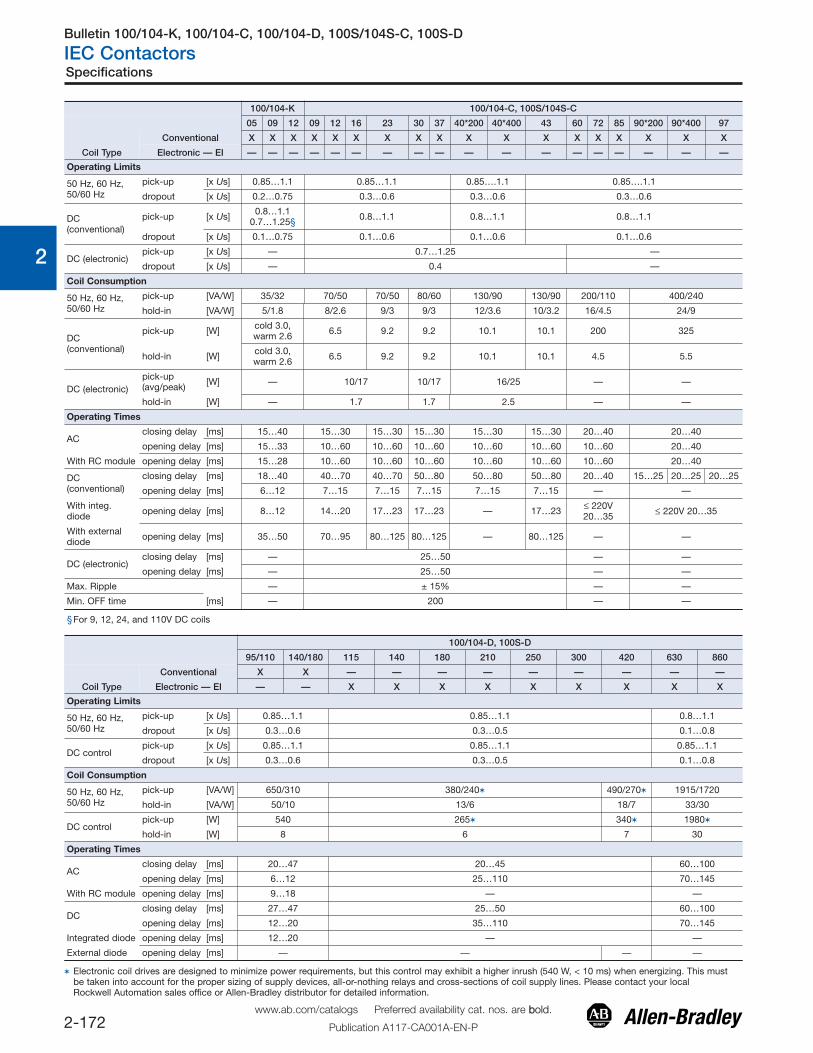
100/104-K 100/104-C, 100S/104S-C
05 09 12 09 12 16 23 30 37 40*200 40*400 43 60 72 85 90*200 90*400 97
Coil Type
Conventional X X X X X X X X X X X X X X X X X X
Electronic — EI — — — — — — — — — — — — — — — — — —
Operating Limits
50 Hz, 60 Hz,50/60 Hz
pick-up [x Us] 0.85…1.1 0.85…1.1 0.85….1.1 0.85….1.1
dropout [x Us] 0.2…0.75 0.3…0.6 0.3…0.6 0.3…0.6
DC(conventional)
pick-up [x Us] 0.8…1.10.7…1.25§ 0.8…1.1 0.8…1.1 0.8…1.1
dropout [x Us] 0.1…0.75 0.1…0.6 0.1…0.6 0.1…0.6
DC (electronic)pick-up [x Us] — 0.7…1.25 —
dropout [x Us] — 0.4 —
Coil Consumption
50 Hz, 60 Hz,50/60 Hz
pick-up [VA/W] 35/32 70/50 70/50 80/60 130/90 130/90 200/110 400/240
hold-in [VA/W] 5/1.8 8/2.6 9/3 9/3 12/3.6 10/3.2 16/4.5 24/9
DC(conventional)
pick-up [W] cold 3.0,warm 2.6 6.5 9.2 9.2 10.1 10.1 200 325
hold-in [W] cold 3.0,warm 2.6 6.5 9.2 9.2 10.1 10.1 4.5 5.5
DC (electronic)pick-up(avg/peak) [W] — 10/17 10/17 16/25 — —
hold-in [W] — 1.7 1.7 2.5 — —
Operating Times
ACclosing delay [ms] 15…40 15…30 15…30 15…30 15…30 15…30 20…40 20…40
opening delay [ms] 15…33 10…60 10…60 10…60 10…60 10…60 10…60 20…40
With RC module opening delay [ms] 15…28 10…60 10…60 10…60 10…60 10…60 10…60 20…40
DC(conventional)
closing delay [ms] 18…40 40…70 40…70 50…80 50…80 50…80 20…40 15…25 20…25 20…25
opening delay [ms] 6…12 7…15 7…15 7…15 7…15 7…15 — —
With integ.diode opening delay [ms] 8…12 14…20 17…23 17…23 — 17…23 ≤ 220V
20…35 ≤ 220V 20…35
With externaldiode opening delay [ms] 35…50 70…95 80…125 80…125 — 80…125 — —
DC (electronic)closing delay [ms] — 25…50 — —
opening delay [ms] — 25…50 — —
Max. Ripple — ± 15% — —
Min. OFF time [ms] — 200 — —
§For 9, 12, 24, and 110V DC coils
100/104-D, 100S-D
95/110 140/180 115 140 180 210 250 300 420 630 860
Coil Type
Conventional X X — — — — — — — — —
Electronic — EI — — X X X X X X X X X
Operating Limits
50 Hz, 60 Hz,50/60 Hz
pick-up [x Us] 0.85…1.1 0.85…1.1 0.8…1.1
dropout [x Us] 0.3…0.6 0.3…0.5 0.1…0.8
DC controlpick-up [x Us] 0.85…1.1 0.85…1.1 0.85…1.1
dropout [x Us] 0.3…0.6 0.3…0.5 0.1…0.8
Coil Consumption
50 Hz, 60 Hz,50/60 Hz
pick-up [VA/W] 650/310 380/240� 490/270� 1915/1720
hold-in [VA/W] 50/10 13/6 18/7 33/30
DC controlpick-up [W] 540 265� 340� 1980�
hold-in [W] 8 6 7 30
Operating Times
ACclosing delay [ms] 20…47 20…45 60…100
opening delay [ms] 6…12 25…110 70…145
With RC module opening delay [ms] 9…18 — —
DCclosing delay [ms] 27…47 25…50 60…100
opening delay [ms] 12…20 35…110 70…145
Integrated diode opening delay [ms] 12…20 — —
External diode opening delay [ms] — — — —
� Electronic coil drives are designed to minimize power requirements, but this control may exhibit a higher inrush (540 W, < 10 ms) when energizing. This mustbe taken into account for the proper sizing of supply devices, all-or-nothing relays and cross-sections of coil supply lines. Please contact your localRockwell Automation sales office or Allen-Bradley distributor for detailed information.
Bulletin 100/104-K, 100/104-C, 100/104-D, 100S/104S-C, 100S-D
IEC Contactors
2-173www.ab.com/catalogs Preferred availability cat. nos. are bbold.
Publication A117-CA001A-EN-P
Specifications
0
1
2
3
4
5
6
7
8
9
10
11
12
13
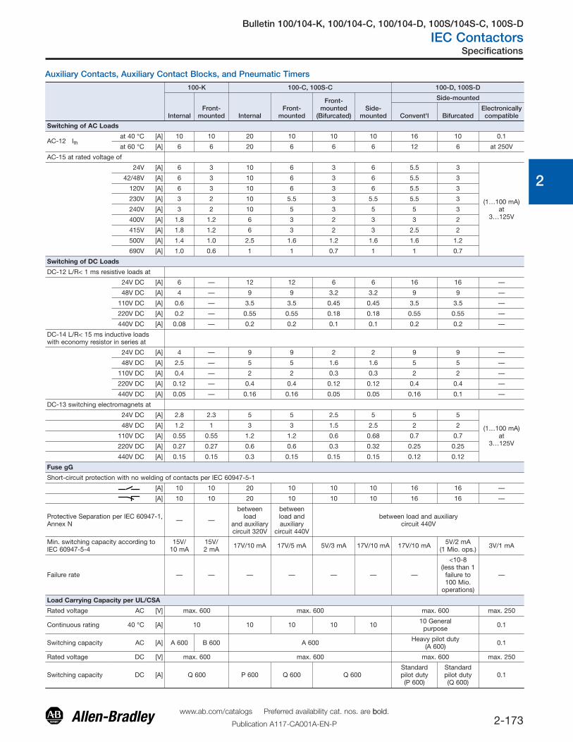
Auxiliary Contacts, Auxiliary Contact Blocks, and Pneumatic Timers
100-K 100-C, 100S-C 100-D, 100S-D
InternalFront-
mounted InternalFront-
mounted
Front-mounted
(Bifurcated)Side-
mounted
Side-mounted
Convent'l BifurcatedElectronicallycompatible
Switching of AC Loads
AC-12 Ithat 40 °C [A] 10 10 20 10 10 10 16 10 0.1
at 60 °C [A] 6 6 20 6 6 6 12 6 at 250V
AC-15 at rated voltage of
24V [A] 6 3 10 6 3 6 5.5 3
(1…100 mA)at
3…125V
42/48V [A] 6 3 10 6 3 6 5.5 3
120V [A] 6 3 10 6 3 6 5.5 3
230V [A] 3 2 10 5.5 3 5.5 5.5 3
240V [A] 3 2 10 5 3 5 5 3
400V [A] 1.8 1.2 6 3 2 3 3 2
415V [A] 1.8 1.2 6 3 2 3 2.5 2
500V [A] 1.4 1.0 2.5 1.6 1.2 1.6 1.6 1.2
690V [A] 1.0 0.6 1 1 0.7 1 1 0.7
Switching of DC Loads
DC-12 L/R< 1 ms resistive loads at
24V DC [A] 6 — 12 12 6 6 16 16 —
48V DC [A] 4 — 9 9 3.2 3.2 9 9 —
110V DC [A] 0.6 — 3.5 3.5 0.45 0.45 3.5 3.5 —
220V DC [A] 0.2 — 0.55 0.55 0.18 0.18 0.55 0.55 —
440V DC [A] 0.08 — 0.2 0.2 0.1 0.1 0.2 0.2 —
DC-14 L/R< 15 ms inductive loadswith economy resistor in series at
24V DC [A] 4 — 9 9 2 2 9 9 —
48V DC [A] 2.5 — 5 5 1.6 1.6 5 5 —
110V DC [A] 0.4 — 2 2 0.3 0.3 2 2 —
220V DC [A] 0.12 — 0.4 0.4 0.12 0.12 0.4 0.4 —
440V DC [A] 0.05 — 0.16 0.16 0.05 0.05 0.16 0.1 —
DC-13 switching electromagnets at
24V DC [A] 2.8 2.3 5 5 2.5 5 5 5
(1…100 mA)at
3…125V
48V DC [A] 1.2 1 3 3 1.5 2.5 2 2
110V DC [A] 0.55 0.55 1.2 1.2 0.6 0.68 0.7 0.7
220V DC [A] 0.27 0.27 0.6 0.6 0.3 0.32 0.25 0.25
440V DC [A] 0.15 0.15 0.3 0.15 0.15 0.15 0.12 0.12
Fuse gG
Short-circuit protection with no welding of contacts per IEC 60947-5-1
[A] 10 10 20 10 10 10 16 16 —
[A] 10 10 20 10 10 10 16 16 —
Protective Separation per IEC 60947-1,Annex N — —
betweenload
and auxiliarycircuit 320V
betweenload andauxiliary
circuit 440V
between load and auxiliarycircuit 440V
Min. switching capacity according toIEC 60947-5-4
15V/10 mA
15V/2 mA 17V/10 mA 17V/5 mA 5V/3 mA 17V/10 mA 17V/10 mA 5V/2 mA
(1 Mio. ops.) 3V/1 mA
Failure rate — — — — — — —
<10-8(less than 1
failure to100 Mio.
operations)
—
Load Carrying Capacity per UL/CSA
Rated voltage AC [V] max. 600 max. 600 max. 600 max. 250
Continuous rating 40 °C [A] 10 10 10 10 10 10 Generalpurpose 0.1
Switching capacity AC [A] A 600 B 600 A 600 Heavy pilot duty(A 600) 0.1
Rated voltage DC [V] max. 600 max. 600 max. 600 max. 250
Switching capacity DC [A] Q 600 P 600 Q 600 Q 600Standardpilot duty(P 600)
Standardpilot duty(Q 600)
0.1
Bulletin 100/104-K, 100/104-C, 100/104-D, 100S/104S-C, 100S-D
IEC Contactors
2-174www.ab.com/catalogs Preferred availability cat. nos. are bbold.
Publication A117-CA001A-EN-P
Specifications
0
1
2
3
4
5
6
7
8
9
10
11
12
13
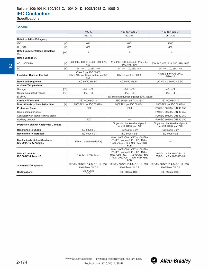
General
100-K 100-C, 100S-C 100-D, 100S-D
05…12 09…97 95…420
Rated Isolation Voltage Ui
IEC [V] 690 690 1000
UL, CSA [V] 600 600 600
Rated Impulse Voltage WithstandUimp
[kV] 6 6 12
Rated Voltage Ue
AC 50/60 Hz [V] 230, 240, 400, 415, 460, 500, 575,690
115, 200, 230, 240, 400, 415, 460,500, 575, 690 230, 240, 400, 415, 500, 690, 1000
DC [V] 24, 48, 110, 220, 440 24, 48, 110, 220, 440 24, 48, 110, 220, 440
Insulation Class of the CoilClass F per IEC 60085
Class 105 insulation system per UL508
Class F per IEC 60085 Class B per VDE 0660,Table 22
Rated coil frequency AC 50/60 Hz, DC AC 50/60 Hz, DC AC 50 Hz, 50/60 Hz, DC
Ambient Temperature
Storage [°C] -55…+80 -55…+80 -40…+80
Operation at rated voltage [°C] -25…+60 -25…+60 -25…+60
at 70 °C 15% current reduction against 60°C values
Climatic Withstand IEC 60068-2-30 IEC 60068-2-1 / -2 / -30 IEC 60068-2-30
Max. Altitude of Installation Site [m] 2000 NN, per IEC 60947-4 2000 NN, per IEC 60947-1 2000 NN, per IEC 60947-4
Protection Class IP2X IP2X IP00 IEC 60529 / DIN 40 050
Single contactor cover — — IP10 IEC 60529 / DIN 40 050
Contactor with frame terminal block — — IP20 IEC 60529 / DIN 40 050
Auxiliary contact IP2X — IP20 IEC 60529 / DIN 40 050
Protection against Accidental Contact — Finger and back-of-hand proofper VDE 0106, part 100
Finger and back-of-hand proofper VDE 0106, part 100
Resistance to Shock IEC 60068-2 IEC 60068-2-27 IEC 60068-2-27
Resistance to Vibration IEC 60068-2 IEC 60068-2-6 IEC 60068-2-6
Mechanically Linked ContactsIEC 60947-5-1, Annex L 100-K… (on main device)
100- / 100S-C09…C97 + 100-FA/-FB/-FC, (except L11, L22), 100- /
100S-C09…C43 + 100-FAB/-FBB/-FCB
—
Mirror ContactsIEC 60947-4 Annex F 100-K… + 100-KF…
100- / 100S-C09…C97 + 100-FA/-FB/-FC, (except L11, L22), 100- /
100S-C09…C97 + 100-SA/SB, 100-/ 100S-C09…C97 + 100-FAB/-FBB/-
FCB
100-D… + 2 x 100-DS1-11100S-D… + 2 x 100S-DS1-11
Standards Compliance IEC/EN 60947-1/-4-1/-5-1; UL 508;CSA 22.2. No. 14
IEC/EN 60947-1/-4-1/-5-1; UL 508;CSA 22.2. No. 14
IEC/EN 60947-1/-4-1/-5-1; UL 508;CSA 22.2. No. 14
Certifications CE, cULusCCC CE, cULus, CCC CE, cULus, CCC
Bulletin 100-K/104-K, 100-C/104-C, 100-D/104-D, 100-G
IEC Contactors
2-180www.ab.com/catalogs Preferred availability cat. nos. are bbold.
Publication A117-CA001A-EN-P
0
1
2
3
4
5
6
7
8
9
10
11
12
13
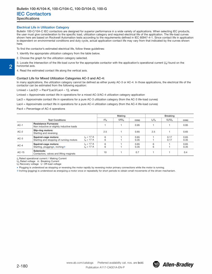
Electrical Life in Utilization CategoryBulletin 100-C/104-C IEC contactors are designed for superior performance in a wide variety of applications. When selecting IEC products,the user must give consideration to the specific load, utilization category and required electrical life of the application. The life-load curvesshown here are based on Rockwell Automation tests according to the requirements defined in IEC 60947-4-1. Since contact life in applicationis dependent on environmental conditions and duty cycle, actual application contact life may vary from that indicated by the curves shownhere.
To find the contactor’s estimated electrical life, follow these guidelines:
1. Identify the appropriate utilization category from the table below.
2. Choose the graph for the utilization category selected.
3. Locate the intersection of the life-load curve for the appropriate contactor with the application’s operational current (Ie) found on thehorizontal axis.
4. Read the estimated contact life along the vertical axis.
Contact Life for Mixed Utilization Categories AC-3 and AC-4:
Test Conditions
Making Breaking
I/Ie U/Ue cosφ Ic/Ie Ur/Ue cosφ
AC-1 Resistance Furnaces:Non inductive or slightly inductive loads 1 1 0.95 1 1 0.95
AC-2 Slip-ring motors:Starting and reversing 2.5 1 0.65 2.5 1 0.65
AC-3 Squirrel-cage motors:Starting and stopping of running motors
Ie < 17 AIe > 17 A
66
11
0.650.35
11
0.170.17
0.650.35
AC-4 Squirrel-cage motors:Starting, plugging�, inching�
Ie < 17 AIe > 17 A
66
11
0.650.35
66
11
0.650.35
AC-15 Soleniods:Contactors, valves and lifting magnets 10 1 0.7 1 1 0.4
Ie Rated operational current I Making CurrentUe Rated voltage Ic Breaking CurrentUr Recovery voltage U Off-load voltage� Plugging is understood as stopping or reversing the motor rapidly by reversing motor primary connections while the motor is running.� Inching (jogging) is understood as energizing a motor once or repeatedly for short periods to obtain small movements of the driven mechanism.
Specifications
In many applications, the utilization category cannot be defined as either purely AC-3 or AC-4. In those applications, the electrical life of thecontactor can be estimated from the following equation:
Lmixed = Lac3/[1 + Pac4*(Lac3/Lac4 – 1)], where:
Lmixed = Approximate contact life in operations for a mixed AC-3/AC-4 utilization category application
Lac3 = Approximate contact life in operations for a pure AC-3 utilization category (from the AC-3 life-load curves)
Lac4 = Approximate contact life in operations for a pure AC-4 utilization category (from the AC-4 life-load curves)
Pac4 = Percentage of AC-4 operations

Bulletin 100-D/104-D
IEC Contactors
2-188www.ab.com/catalogs Preferred availability cat. nos. are bbold.
Publication A117-CA001A-EN-P
0
1
2
3
4
5
6
7
8
9
10
11
12
13
Bulletin 100-D/104-D Life-Load CurvesAC-3, AC-1
AC-4
Specifications
Electrical life span AC-3 Switching of squirrel-cage motors while starting
AC-1 Non- or slightly inductive loads, resistance furnaces, Ue = 415V AC
0.10
1.00
10.00
000100101
Rated operating current Ie AC-3 [A](Dashed curves - - - - - AC-1 only, open)
Cont
act l
ife
[Mio
. of o
ps.]
100-D115
100-D140
100-D180
100-D210
100-D250
100-D300
100-D420
Electrical life spanAC-4 Stepping of squirrel-cage motors, Ue = 415V AC
0.010
0.100
1.000
10.000
0001001011
Rated operating current, Ie AC-4 [A]
Cont
act l
ife
[mill
ions
of o
ps.]
100-D115
100-D140
100-D180
100-D210
100-D250
100-D300
100-D420
Bulletin 100-D/104-D
IEC Contactors
2-189www.ab.com/catalogs Preferred availability cat. nos. are bbold.
Publication A117-CA001A-EN-P
0
1
2
3
4
5
6
7
8
9
10
11
12
13
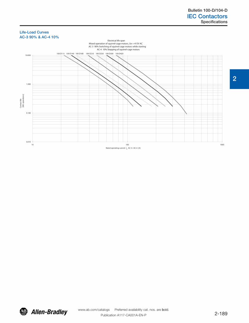
Life-Load CurvesAC-3 90% & AC-4 10%
Specifications
Electrical life spanMixed operation of squirrel-cage motors, Ue = 415V AC
AC-3 90% Switching of squirrel-cage motors while starting AC-4 10% Stepping of squirrel-cage motors
0.010
0.100
1.000
10.000
10 100 1000
Rated operating current Ie AC-3 / AC-4 [A]
Cont
act l
ife
[Mil.
ope
ratio
ns]
100-D115 100-D140 100-D180 100-D210 100-D250 100-D300 100-D420

![inDEx [ ] · PDF fileCEi En50347 iEC 60072-1 iEC 60072-2 The coupling dimensions are in compliance with the following standards: unEL 13113-71 for the B3 mounting and for other frame](https://img.pdfslide.us/doc/110x75/5a9f52a87f8b9a71178c9dee/index-en50347-iec-60072-1-iec-60072-2-the-coupling-dimensions-are-in-compliance.jpg)


![Public Input No. 140-NFPA 79-2016 [ Global Input ] · PDF filePublic Input No. 140-NFPA 79-2016 [ Global Input ] ... International Electrotechnical Commission, 3, ... IEC 60072–2,](https://img.pdfslide.us/doc/110x75/5a9f52a87f8b9a71178c9dd7/public-input-no-140-nfpa-79-2016-global-input-input-no-140-nfpa-79-2016-.jpg)
