Embed Size (px)
Citation preview
B U L L E T
by Pete Snidal
This Manual is Also Available on CD ROM
Ask your local Royal Enfield dealer or visit: http://www.webhome.idirect.com/-snidey/manual/
Copyright 02002 by Pete Snidal. All Rights Reserved No portion of this manual may be reproduced in any form without permission.
unless the reproduction is for the sole use of the purchaser.
And Rnally, a brief word from our solicitor: The author accepts NO responsibility, expressed or implied. for any andlor all damages to persons or property as a
result of following any of the instructions laid out in this manual.
I I The Enfield BULLET MANUAL by Pete Snidal O 2002
INDEX
Chapter 6 . Engine Work Engine Exploded View (also see Appendix) ..- 59 The Cork Quill Seal ................... .. 59
Remove and Replacing the Timing Cover - 60 . . The Tlmlng Gears ... - ............... ........... 64
. . . . Checking and Setting lgnltlon Tlmlng ........................ - 65
. . Decldlng on Top End Work . - ....... 72 ... Removing Cylinder Head ...................................... ....... . 75
Replacing Cylinder Head ....- 80 . Removing Cylinder Barrel 83
Replacing Cylinder Barrel - . 89 . . Spllttlng the Crankcase 9 I
Chapter 7 . Suspension Operation of The Front Suspension - . 95 The Casquette/Fork Crown/Steering Head .- .. 96 The Stanchion/Maintube-Slider Assemblies 98
The Rear Suspension - -- ......... . -- 10 I
Chapter 8 -The Primary Drive Removing the Clutch - ...... I03
....... Replacing the Clutch - ............ .. I05
Exploded View - the 350 Clutch .. .- 105
Removing the Alternator Rotor .......... . 106 Replacing the Alternator Rotor - .... - I07 The ES Starter Drive System ......................... I07
Chapter 9 . Gearbox Work Exploded View of Gearbox I08 Adjusting The Neutral Finder . I09
Removing and Replacing Countershaft Sprocket - ... . 109
Removing The Gearbox Covers I I 0 Complete Strip I 13
. . Examlnatlon of Gearbox Parts .. ....... .. .. 1 1 4
Gearbox Reassembly .. .... - I I5
Correcting Gear Changing Problems - - 1 16 Solving Kickstarter Problems . 123
...... Conversion Back to Right Foot Gearshift 124
The 5 Speed Gearbox - Overview, Trouble Shooting, Dismantling, Assembly Chapter 9 Appendix
IV The Enfield BULLET MANUAL by Pete Snidal Q 2002
Chapter I 0 -The Carburetors The VM24 Mikcarb - 350cc models I32 The VM28 Mikcarb - 500cc models 133 The Bing Carbureto - - - 134 The Amal Monoblo 135 The Amal Concentric Carbureto 136 Carburetor Adjustment 137
Chapter I l - Electrical Work Electrical Troubleshooting The US/Canada Models ( The US Models (Post Mid-99) - Wiring Diagram 143 The Home (Indian) Models - Wiring Diagram 1 45
. . The UK Models (Pre ES) - Wlrlng Diagram 146 Export Electric Start Models - Wiring Diagram 146 Connections - Colours and Terminals 153
Chapter 1 2 - Performance . . . Performance Mod~f~catlons I 60
Chapter 13 - Clean Air Additions The Pulse Air System 1 65 Crankcase Breather Condenser Tank 1 67
APPENDIX Engine Tightening Torques 1 70 Chassis Tightening Torque 17 1 Service Limits and Clearances 172 Inch/Metric Conversion Table I73
Engine Exploded View - - I77 What Year is My Bullet Troubleshooting .........
The Enfield BULLET MANUAL by Pete Snidal O 2002 v
FORWARD
HOWTHIS MANUAL CAMETO BE
'There are two things I've been for most of my 6 1 years on this planet. One is a wanna-be technical writer; the
other a Royal Enfield Bullet fan. Other motorcycles, too, but the first motorcycle I was able to get my hands on
(that could be made to run) was an ex-WD 350 Royal Enfield Bullet - the CanadiadBritish Army bike from WWII.
By that time, I had already learned that the second thing you have to have, after you acquire just about any piece
of machinery is a good manual. Unfortunately, I couldn't find any manual for my "new" motorcycle. The situation
was complicated somewhat by the fact that most of it came in a couple of cardboard boxes - it was in a state of
"some assembly required."
The only book(s) I could find on the subject were one afficionado manual, which assumed a widespread and general knowledge of motorcycles, and was a sort of pocket-size coffee-table magazine, called Book Of The
Royal Enfield. It offered up lots of esoteric information, such as what years the "famous pre-war Enfield V-Twins"
were produced, but very few specifics on my mundane little workhorse 350. The only other book I could find
that even mentioned Royal Enfields was the excellent, but not particularly detailed due to its universal coverage,
the Nicholson Brothers' Modern Motorcycling, an early '50's edition.
This was only the first of many Royal Enfields that seemed to come my way as a young enthusiast in Vancouver,
BC, Canada in the '50's. Although there was only one Enfield dealer in Vancouver ever, and him for only part of
one year, there were a few pre-"unit" Bullets - models G and 12 - and a half-dozen of the post-'53 swingarm
frame "unit" models, like the Indian-made 1956-2003 350/500 bullets of today.
Although I owned a half-dozen Bullets in The Day, I never did find a decent service manual. Most manufacturers
of British Motorcycles in the '50's seemed to assume a high degree of mechanical ability on the part of any owners,
dealers, or their mechanics. The only even modestly comprehensive Shop Manuals I ever ran across were for A]S/Matchless Singles (AMC) and for the Triumph Twins. These were, don't forget, the days before Clymer,
Haynes, et al., and the only suppliers of manuals of any kind were the factories themselves. The Royal Enfield
manual was a toolbox-sized pamphlet, which contained a few of the most necessary things to know, if you could
read between the lines, and had enough basic mechanical know-how to be able to understand them. I t was
enough, though, and I worked my way through repair and
restoration of a number of "fixer-uppers," mostly but not
confined to Bullets, over the next few years.
I sold "Ralph," my last running Bullet - a 1957 MX350
"Moto Cross Bullet," which I had painstakingly restored in 196
a few years later while in college. Although a few years aftel
that, I got back into motorcycling - mostly dirt competition for some time, finally back into street riding, mostly on
Triumph twins - I never ran across another Bullet. Finally,
about 1975,l began to hear rumours that they had been transplanted to India, and had been being made there, on
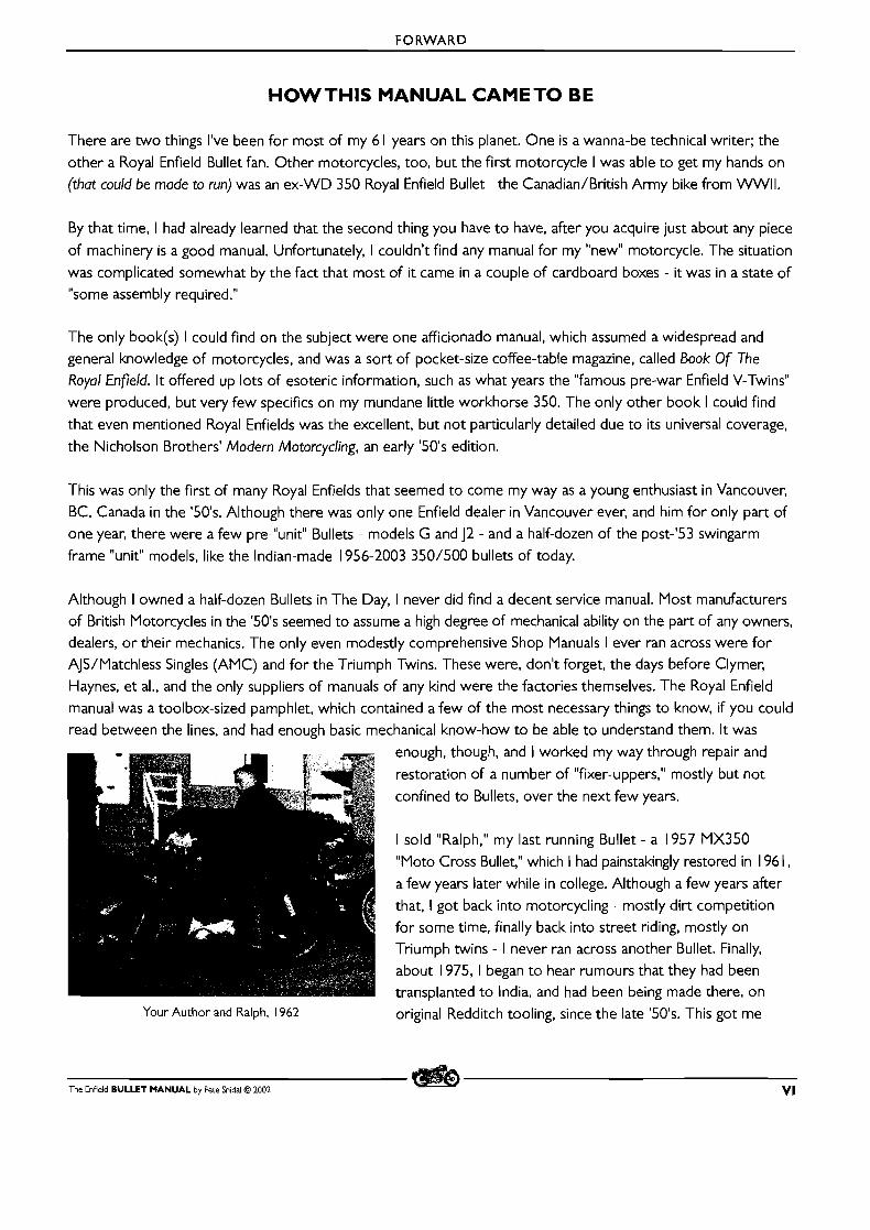
Your Author and Ralph, 1962 original Redditch tooling, since the late '50's. This got me
The Enfield BULLET MANUAL by Pete Snidal O 2002 VI

FORWARD
interested, and by the time the internet started to come alive, in the late '801s, I was in more o r less constant
contact with many Bullet owners all over the world, with whom I found myself exchanging reams of information about my first motorcycle love.
One of the things I found was that there was still no really satisfactory manual, especially for beginners - and
there were plenty of people buying new Bullets, primarily for the nostalgia value. Nostalgia over a time of simpler
motorcycles, that looked and sounded like motorcycles, and over a misspent youth that didn't spend enough
time in Auto Shop, and too much time in Bookkeeping classes, gymnasiums, Physics and Chem labs, and the like.
And some of those with this kind of youth now wanted to master the black (fingered) arts of motorcycle mechanics, with particular interest t o maintaining their new instant collector pieces.
After a time, I began t o toy with the idea of writing a comprehensive manual, a sort of Idiot's Guide To Volkswagen
Repair, something that would enable the complete newbie to get a grip on the esoterics of maintaining his RE Bullet,
yet hold all the information needed for the experienced mechanic to do any and everything necessary, from basic
tune-up to complete overhaul. This is especially important, not only because of the unique demographic to which these machines appeal, but also since the few Dealers are so thin on the ground. Even for those not completely desirous of becoming late-in-age mechanics, the appeal of being able to avoid trips of hundreds of miles to have
a 15 minute procedure done on your motorcycle seems t o me unbeatable.
Hence this manual. It is the product of many hundreds of hours of dedicated work on my part, having taken a lot of my spare time in the last couple of years. My bibliography/credits must include many sources, beginning with the two books mentioned above, many years of Bullet work of all kinds, conversation with owners face t o
face, and especially, via the internet, from all over the world, the original Redditch manuals, such as they were (fortunately, I stil l have mine), the REM manual, Gopi and friends with their very generous tripod.com manual
project (www.workshopmanuol.tripod.com), and particularly to a few Enfield Bullet professionals. I name one of
the partners of the Canadian Enfield Dealer, Terry Smith, Guru Nandan, of Bulletech in India (www.bulletech.com)
and Dan Holmes of DRS Cycle, in Goshen, Indiana, all of whom have been very helpful consultants in this project. (Dan's Very Useful Enfield FAQ, from his DRS Cycle website, dncvcle.safeshopper.com) Thank you also to my "Beta
Testers," who provided the necessary proving ground for me t o evaluate the usefulness of various sections of the manual.
This manual is also available on CD. If you find yourself in possession of a bootleg copy, and you feel that the poor slob who spent so much of his time making your life easier is worth a contribution, please remit a cheque in the currency of your country, in the amount of your choosing, to:
Thank you.
I have faith that I'll be repaid by the majority of Bulleteers, honest fun-lovers that they are. Peace be with you!
"We're All In This Together1'
Pete Snidal, [email protected]
VII The Enfield BULLET MANUAL by Pete Snidal @ 2002
CHAPTER I - FOUR STROKE ENGINE BASICS
CHAPTER I - FOUR STROKE ENGINE BASICS
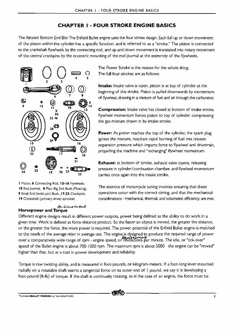
The Related Bottom End Bits The Enfield Bullet engine uses the four stroke design. Each full up or down movement
of the piston within the cylinder has a specific function, and is referred to as a "stroke." The piston is connected
to the crankshaft flywheels by the connecting rod, and up-and-down movement is translated into rotary movement
of the central crankpins by the eccentric mounting of the rod journal at the extremity of the flywheels.
The Power Stroke is the reason for the whole thing.
The full four strokes are as follows:
Intake: Intake valve is open, piston is at top of cylinder at the
beginning of this stroke. Piston is pulled downwards by momentum
of flywheel, drawing in a mixture of fuel and air through the carburetor.
Compression: Intake valve has closed at bottom of intake stroke,
flywheel momentum forces piston to top of cylinder, compressing the gas mixture drawn in by intake stroke.
Power: As piston reaches the top of the cylinder, the spark plug
ignites the mixture, resultant rapid burning of fuel mix creates
expansion pressure which imparts force to flywheel and drivetrain,
propelling the machine and "recharging" flywheel momentum.
Exhaust: at bottom of stroke, exhaust valve opens, releasing
pressure in cylinder/combustion chamber, and flywheel momentum
carries once again into the intake stroke.
I Piston. 6 Connecting Rod. 1 5- 16 Flywheels,
Rod journal, 8 Plain Big End Bush (Floating), The essence of motorcycle tuning involves ensuring that these
9 Small End (wrist pin) Bush ,17-23 Crankpins. operations occur with the correct timing, and that the mechanical
19 Crankshaft (primary drive) sprocket considerations - mechanical, thermal, and volumetric efficiency, are met.
& LLGO %&/: Horsepower and Torque Different engine designs result in different power outputs, power being defined as the ability to do work in a given time. Work is defined as force-distance product. So the faster an object is moved, the greater the distance,
or the greater the force, the more power is required. 'The power potential of the Enfield Bullet engine is matched
to the needs of the average rider in average use. The engine is designed to produce the required range of power e.&-9
over a comparatively wide range of rpm - engine speed, o&%%utlons per minute. The idle. o r "tick-over"
speed of the Bullet engine is about 700- 1000 rpm. The maximum rpm is about 5000 - the engine can be "rewed"
higher than that, but at a cost in power development and reliability.
Torque is raw twisting ability, and is measured in foot-pounds, or kilogram-meters. If a foot-long lever mounted
radially on a rotatable shaft exerts a tangential force on its outer end of I pound, we say it is developing a
foot-pound (ft-lb) of torque. If the shaft is continually rotating, as in the case of an engine, the force must be
The Enfield B U L L E T M A N U A L by Pete Snidal O 2002 I

CHAPTER I - FOUR STROKE ENGINE BASICS
measured with some sort of brake, which applies counter-torque t o the shaft and measures the force required.
This is the principle of the Prony Brake, a basic torque/horsepower measuring device, which gives HP readings
as Brake Horsepower. The torque readings of the Prony Brake, combined with readings of rpm, to introduce
the time factor, result in this BHP reading. A Horsepower is defined as 550 ft-lb/sec.
What all this means t o the rider of a motorcycle is that the engine may be
I I I I I expected to produce various forces with 30 1 I
I I
various throttle readings at various rpms. I I
There will be an ideal rprn for maximum 20
power development - at full throttle, and a much wider range of rpm for less 15
power at lower throttle readings. This is 10 best demonstrated with a power graph. This is not meant to represent any specific 5
engine, but is an off- the-cuff typical chart. 0
Note the sudden drop of of HP at the o 5 1 0 15 20 25 30 35 40 45 50 55
end of its range, the relatively wider RPM x 100
range of peak torque over peak HP, and the lower occurance of the torque peak A Typical HP/Torque Chart (--- ~orse~ower) (- ~ o r ~ u e )
than that of HP. The torque/hp reading shown would all have been read at the same throttle opening - generally full open when an engine is tested on a
brake or dynamometer - the throttle is opened fully, and measured counter-torque is applied to hold the engine at
given rpms in steps and the readings recorded to make the chart. O f course, in actual general use, the motorcyclist
seldom, if ever, uses full throttle, but the shape, placement, and duration of the curves would be similar.
PERFORMANCE BOOSTING Engine modifications can be made t o boost performance change the power and torque curves. A highly-tuned
racing engine would have a higher HP peak, over a shorter range, higher up the rprn band. Torque would likely
suffer, and the torque band would be shorter and also higher up the rprn range. Thus, the price for "more power" is measured not only in dollars, but also in tractability and ease of operation - the engine must be operated
within a narrower rprn "power band," and at higher rprn in all cases, resulting in lower reliability. Performance
modifications are always a trade-off, in cost, noise, reliability, and ease of riding.
So the first thing the new Bullet rider should consider is that his mount has been designed to provide the best
all-around power and reliability for most riders, and that seeking more power will result in less tractability, and
less reliability. Speed tuning is, however, dealt with at the end of this manual in Chapter 12.
2 The Enfield BULLET MANUAL by Pete Snidal O 2002

CHAPTER 2 - OPERATION OF THE MOTORCYCLE
CHAPTER 2 - OPERATION OFTHE MOTORCYCLE Warning: There is Much More to RidingThan Just Operation
The following is a treatise which is designed to help the new owner understand the principles of operation of the
motorcycle. Although this will be enough actually to ride the machine, it is strongly recommended that the new
rider take advantage of a Motorcycle Training Programme of some sort. Statistics prove beyond any reasonable doubt that there is a very significant safety advantage to learning to ride a motorcycle from a professional trainer
- even more so than with automobiles. There is much more to staying alive in traffic on a motorcycle than just
being able to operate the machine. Most insurance companies reflect this reality by offering premium incentives
to take such courses, and it is a very good idea in any event. There are many considerations involved in operating
a motorcycle on the streets which go beyond the scope of a shop manual such as this, but which are nonetheless
extremely important to your personal safety. Self-taught motorcycle operation is N O T recommended! Failure to
heed this warning can get you seriously hurt or worse. Motorcycle training courses are the best investment the
new rider can make. Consider the following information advice for off-road riding only.
STARTING DRILL
Single cylinder Cstroke motorcycles, although not really difficult to start, require that their owners develop a familiarity
with the process. A review of the four strokes on the engine, laid out in chapter I, will be a big help to understanding.
Breaking the Clutch Free If the machine has been sitting for a time, it may be that, once you've got it started, you will have trouble engaging
first gear without some grinding due to the clutch not breaking entirely free on disengagement. This can be made
easier by breaking the clutch free before starting, by hauling in the clutch lever and giving the kickstarter a few
strokes before attempting to start.
Actual Starting If the piston is slowly brought as far up a compression stroke as operation of the kickstarter will allow, you will
then find that you can stand on the pedal, and even bounce your weight on it, and in most cases it won't continue to turn over the motor. Obviously, this is not the best place for the piston to be when you attempt a kickstart.
O n the other hand, if the piston is at the beginning of a power stroke, and the would-be rider, first having taken
up all the slack in the kickstarter mechanism, then swings his full weight into a good, long, slow transfer, the
crankshaft/flywheel assembly will draw the piston all the way down in a "blank" power stroke, roll over the bottom,
at which point the exhaust valve will open, allowing unimpeded piston movement back up the cylinder, whereupon
the exhaust valve will close, but the intake valve will open, and the piston will once again travel down-cylinder
relatively unimpeded, drawing in in air/fuel mixture as it does. A t the bottom of this intake stroke, the intake
valve will close, and the freshly-inducted mixture will be compressed as the piston travels once more up the
cylinder, aided by the flywheel momentum, which has by now built up considerably, and the engine will likely fire
on the ensuing power stroke - if not on the f i rs t one, on the next one, 2 revolutions later, to which will arrive
on flywheel momentum alone.
The Enfield BULLET MANUAL by Pete Snidal O 2002 3
CHAPTER 2 - OPERATION OF THE MOTORCYCLE
That, in a nutshell, is the "trick" to starting a big single, which is nothing like the drill for a multi-cylinder engine, with which you just swing your weight on the kickstarter, paying no attention to engine position. The only
remaining question is how to get the piston to the proper position. Here's how:
I. Apply pressure to the kickstarter until it stops against the resistance of a compression stroke.
2. Using the decompression lever, apply just an inch or two more movement t o the kickstart lever, listening as
you do for the "wheeze" of air into the exhaust pipe from the decompressor valve. (Decompressor cable broken? No problem; just depress the top of the valvestem directly with your thumb - it may be
hot if the bike's been running lately)
3. Once the piston has been eased over the top of the compression stroke, you're ready to start. Turn on the fuel valve, apply the choke lever, (or tickle the carburetor until fuel drips if equipped with an Amal,) turn on the ignition, and with the slack taken up in the kickstarter mechanism, apply a long, deliberate weight transfer to the lever.
Throttle opening: although this will vary from machine t o machine, there will be a definite "best" place for the
throttle to be during kickstarting, and it important to develop the skill necessary to maintain this precise setting as your body moves up and down during the weight transfer. Often, the best throttle setting is just a bit above idle - about I /8"/3mm of cable travel. In some cases, less will be required, in some a bit more. Experiment
and find the best setting for your machine.
That's all there usually is t o kickstarting a big single. Done properly, it can be done without taking yourself off the seat - often t o the amazement of the non-cognoscenti.
Flooded Starting Sometimes, in cases of difficult starting, the machine will "flood" - induct an excess of fuel without starting.
Once you have rolled it over 4 or 5 times without success, it is often useful to assume that it has now flooded. This condition requires a change in throttle setting. First de-apply the choke, and then roll on 3/4 throttle.
Maintaining this setting as you roll through the weight transfer, attempt to start it in this way for 4 or 5 kicks. This will usually serve to clear it out, and get it started. WARNING: be ready to roll off that 3/4 throttle as
soon as it catches! 3/4 is plenty of throttle t o damage an unloaded engine!
One last time: Sometimes, if, after this procedure, if the machine still doesn't start, a kick or two with N O throttle
may produce a little firing. If so, do this a few time, and then resume with the small throttle opening. If not, it's time for one of the next two possibilities: See Troubleshooting or Push-Starting on page 8. However, let us assume it's running, and it's time to move off:
LEARNING TO OPERATE THE MACHINE
Following is a treatise on learning to operate the machine itself. The experienced owner will want t o skip this
next part. I t is hoped that this treatment of the basics of riding will prove t o be of help t o the first-time owner - but DON'T forget that riding course!
4 The Enfield BULLET MANUAL by Pete Snidal O 2002
CHAPTER 2 - OPERATION OF THE MOTORCYCLE
LESSON I: MOVING OFF AND COMING TO A HALT
Once the machine is started, and has had a minute or two to warm up, it may be ridden by engaging first gear and
moving off. To engage first gear, i t will be necessary first to disengage the clutch by pulling in the clutch lever.
Then apply upward pressure to the gearshift lever to engage first gear. (Downward Pressure in LH shifl models)
Increase the throttle rpm slightly as you check the roadway ahead of you (and to your rear if you'll be pulling out
into possible trafic), and slowly release the clutch lever until you feel the machine just begin to move. A t this point,
"freeze" your clutch lever hand until the machine picks up speed (you may increase the engine rpm at this point as well)
and once the speed has picked up about as far as it will, slowly continue the release of the lever until it is fully out.
The Stop Reflex This is a most important thing to learn. In order to stop the motorcycle, you must disengage the clutch and apply the brake(s). The slow-speed reflex should consist merely of simultaneously winding off the throttle, pulling in the
clutch lever, and applying the rear brake, being ready to support the machine with the non-brake leg as i t comes
to a halt. You should practice the coordination of these three movements before even starting the bike, and once
you're actually riding around in I s t gear, practice them until they become almost second nature. It's no fun finding
yourself going into a pond, or a fence, or the side of a barn or tree and having to intellectualize your way through
the moves required to stop - i t must be second nature before you start.
D o not neglect use of the front brake. Since, at any speed, the front brake does 75% of your stopping, you want
to use it from the beginning. But, if you are turning, or on soft or slippery ground, locking up the front wheel will
almost certainly result in a fall. So don't use it unless you're upright, going straight, and the ground offers good
traction. However, very early in your riding career, you want always to be thinking Front Brake. Never depend on
the rear brake to stop you - i ts main use is to keep the machine straight while the front brake does the stopping.
- A t low speeds, however, the rear brake is usually enough.
Throttle Control One of the greatest difficulties to the new rider is throttle control. Having the throttle as one of the things you hold
onto can make for interesting situations. You want, from the beginning, to practice holding your right wrist rigid as
you turn the handlebars, rotating the throttle only when you want to increase enginehehide speed. Once you get
moving with the clutch engaged, you should practice gradual increases and decreases in throttle opening - speeding
up a bit, and then slowing down. Do this a number of times, as well as stopping and starting out, until you are
comfortable with it. This would be a good time to end your first session with motorcycle operation. You might try
maneuvering around a bit - making slow turns and such - as well. And most importantly, developing The Stop Reflex
For your next session, you may want to try going a little faster, which will require changing up.
LESSON 2: UPSHIFTING
For your second session, first review to yourself what you've learned in the first session. Start out by practicing
starting out and stopping for awhile, and then move into the next step: changing up.
Once you've run out of rpm in first gear, to change to second, you'll want to do three things at once, followed by three more. First, you'll want simultaneously to disengage the clutch by pulling in the lever, back off the throttle
The Enfield BULLET MANUAL by Pete Snidal O 2002 5
CHAPTER 2 - OPERATION OF THE MOTORCYCLE
to full closed, and press the gear lever firmly downwards (or pull it upwards, depending on whether it's LH or RH ship) to engage second gear. Then, you'll want to do the second three things: apply throttle, engage the clutch by releasing
the lever, and release the pressure on the gear lever. The neophyte may want to practice the movements while sitting down reading this; right hand tw i s t out/left hand clasp, right foot down (or lefi up, depending on model), followed by
right hand tw is t id lef t hand release/right foot up. A little practice in coordinating these two sets of three movements
off the bike - while riding the bus to work, sitting watching TV, or at any time, will work wonders later "on the job."
It will also help to think about exactly what you're doing. The reason for the throttle work is actually to reduce
the engine rpm to that necessary for the next higher gear at the roadspeed at which you're changing gear. The
reason for the clutch action is merely to smoothen out any kinks in the operation - if the coordination of rpm change with gear change is done perfectly, the clutch isn't actually even necessary. And of course the foot work
is t o cause the ratchet gear change mechanism to move actual gears in the gearbox t o provide a different ratio. (The gearchange mechanism "ratchets" to change gears only one at a time - it won't go directly from 1st to 3rd or 4th, for instance, with only one poke - although it will go through neutral from 1st to 2nd, or back from 2nd to 1st.)
The Ratchet Shift Remember, the ratchet mechanism in the gearbox stops the linkage at the next gear each time you change - you don't have to "feel" your way to the next gear. Operate the lever positively, and maintain pressure at the "stop" as you let out the clutch. If you experience any difficulty in changing gear in this way, your gearbox may need
adjustment. This is dealt with in detail in a later chapter.
LESSON 3: DOWNSHIFTING
Downshifting is similar to upshifting, with the difference being that, rather than the engine rpm decreasing with
engagement of the next gear, it will have to increase, since a lower gear is being engaged. This means that, as the
gear is engaged with an upward movement of the foot in the first set of actions, the throttle must be "blipped," and
in the second set of actions, throttle must be applied a little sooner relative to clutch engagement. This may be practiced with changes from 2nd back to first, although it will be found that changes from 3rd to 2nd will be easier to make smoothly, since the ratios are closer. Riding with, or just watching, an experienced rider going through the gears will be invaluable in helping you develop the "feel" for good gear changing. The above considerations will be found t o apply in all changes, up and down, between all gear combinations.
Trouble Changing Gears The Enfield gearbox is unique in i ts ratchet mechanism, which is adjustable, and could be out of adjustment, even
when supplied new from the factory. If the new rider finds s/he just can't "get the hang of it," it may prove worthwhile to have an experienced rider give it a try, since referral to the chapter on gearbox adjustment may prove necessary.
Coming to a Halt In an automobile, i t is not regular practice t o change down from top gear to 3rd and 2nd before coming to a stop
and changing t o neutral for the wait at the stoplight or wherever. With most motorcycles, the rider must do exactly
this - as the roadspeed lowers, the rider changes down to 3rd gear, then 2nd, then slips it into neutral as s/he
coast to the final stop. For some reason, the designers at Royal Enfield, many years ago, decided to add a truly unique feature - the Neutral Finder. This allows the rider to change directly from any of the top three gears
6 The Enfield BULLET MANUAL by Pete Snidal O 2002
CHAPTER 2 - OPERATION OF THE MOTORCYCLE
directly to neutral as the machine is brought to a halt (nb: while sti l l moving, however slightly - it will not work well
once movement has ceased.) This is the reason for the "extra" lever on the Enfield gearbox. For those not inclined
to go through downshifting as they slow to a stop, the clutch may be disengaged, and pressing the neutral finder
will bring the gearbox directly to neutral, at which point the clutch lever may be released, and will not be
required again until the time comes to engage first gear to move off once again.
Stay Off'rhat Clutch Lever! In any event, the clutch lever should not be used when the machine is standing still for any period of time - the
gearbox should be in neutral and the lever released. The release mechanism is simply not designed for sitting at a
standstill in gear, and will soon give trouble if this practice is followed. Get to neutral, whether by using the neutral
finder, or by downshifting down to second, and then slipping it the "half notch" further to neutral, and release the
clutch lever when coming to a stop. (nb: it is normal to find great dificulty in selecting neutral fiom a gear eg. second
when the machine is no longer moving, but the engine is running. Best to do it while sti l l moving, even slightly.)
IMPORTANT SAFETY NOTE: 'The experienced street rider, at this point, if stopped at a traffic light o r stop sign,
will be checking his mirror constantly, on the alert for someone approaching from the rear who doesn't see him, and
is bent on bending. If this happens, it is a simple matter to pull in the clutch, pull/push it into first, and get out of
there! - The danger passes once the first auto or truck stops behind you. Until then, have your escape planned and
be ready! There are few seasoned motorcyclists who don't know of someone who's been killed this way! Motorcycles are not only invisible to many motorists; they seem to render stop lights and stop signs invisible as well!
Use of the Brakes Finally, a word on braking. The motorcycle differs from the auto in that differential control of braking is another
skill which must be developed. Since about 75% of the braking force is exerted by the front wheel brake, it is
important to learn to use this effectively. However, since the steering and stability can be adversely affected by
misuse of this brake, some learning must be done. The front brake should not be applied in a turning situation, nor
in conditions of poor traction - such as the gravel so often found in the region of stop signs onto major road-
ways. The rear brake should always be applied in conjunction with the front one - it tends to keep things going
straight, as well as supplementing the braking of the front. Engine compression is also an effective part of slowing
down with a motorcycle, and changing down a gear as you begin to apply brakes is a common practice. I t is a
good idea to be as sensitive as possible to how your brakes work, since when on two wheels, locking up a
wheel, especially the front one, can have disastrous results compared to those resulting from the same action in
an automotive situation. When your front wheel locks, your steering disappears - always be ready to get off that front brake!
IMPORTANT! It is important always to assess the condition of the roadway immediately as you apply brakes. If you encounter gravel,
sand, or other looseness of surface with the front brake applied heavily, you will experience injury and embarrassment!
The Enfield BULLET MANUAL by Pete Snidal O 2002 7
CHAPTER 2 - OPERATION OF THE MOTORCYCLE
PUTTINGTHE MACHINE AWAY
When you have finished riding your Bullet for the day, attention should be paid to proper storage. It should be kept in a safe, secure place, out of the weather - being rained on will bring about consequences with water in
the fuel, carburetor, electric system, and also make the seat wet. The machine should, at the very least, be under a cover of some kind.
You should also be very concerned with security. Motorcycles are a very concentrated resource - little space or weight compared to value. They are worth more in pieces than whole, and can be rendered so in little time by experienced thieves. 'They can be carried away easily to a nearby van or utility, or even stuffed in the trunk of a
car, whether the wheels are locked or not. At very least, you need to have your machine securely locked to
something immovable, such as a tree or lamppost, although this will just limit the possible thieves to those with
strong boltcutters. When stopping for a meal or other refreshment, it is highly advisable to park your machine where it may be observed through a window, locked as well as you can for those inevitable trips to the washroom.
You should consider an alarm, but remember that it is only useful if someone within hearing is prepared to respond if it's tripped. This writer has usually kept his machines in a locked building, chained to a support post with a very large chain, and the building is bugged to silent alarm to my home. And I live in a very quiet part of the country, crime-wise. Summary: be as careful as you can. It's a real heart-breaker to lose your motorcycle investment in the space of a few minutes.
TROUBLE SHOOTING - STARTING
Generally, if no success is attained after having gone through the flooded starting drills, it's time to do some trouble shooting. This will be described below. One last alternative is to attempt a push start.
Push Starting The last resort for the otherwise hopeless is push starting - useful in cases of bad flooding, otherwise extremely
difficult starting, or broken or missing kickstart lever/mechanism. Here's the drill for it:
First, the safety considerations. First, be certain that you have the strength and balance to support the machine while running alongside it while pushing, and to step onto the left footrest and swing yourself onto the seat while the machine is moving. If not, do not attempt the following, as you'll just end up dropping the bike, and hurting it or yourself in the process.
I. Put the machine in 2nd gear. Standing on the left side, pull it backwards until the piston on compression stops movement of the bike.
2. Turn on the fuel tap and apply choke or tickle carb as applicable - nb if flooded, disregard the choke.
3. Pull in the clutch lever, and pull the motorcycle backwards a foot or so (the length of one of your feet) to free
the clutch - you'll feel it free up. Then turn on the ignition.
8 The Enfield BULLET MANUAL by Pete Snidal O 2002
CHAPTER 2 - TROUBLESHOOTING
4. Alone, or with the help of a friend, preferably downhill, begin to push the machine until you get it up to about
the fastest speed you think you'll be able to maintain for I 0 or 15 yarddmetres. When you're at that speed,
applying no throttle, release the clutch lever, continuing to push as hard as you can. (Note to middle-aged
owners: monitor your heartbeat as you do this - getting your bike running is of no value if it stops your heart!)
Do not apply any throttle until the machine is up to speed.
"Bump" starting - in cases of poor traction, applying some weight to the rear wheel at the moment of clutch
engagement may be necessary. For this reason, it is common among those in the know to do a little leap
which momentarily puts them side-saddle on the seat, and which applies their weight to the wheel as necessary for traction. There are a few complications to this move - one of which is to lean the bike slightly towards
you as you jump towards it. (I've never seen anyone go over backwards, but I'd imagine it can be done!) Recommended: try without the "bump" unless it becomes absolutely necessary. Once the engine begins to
turn, it will be helpful to get back onto the ground and continue pushing.
5. The motor should now be turning over at a fairly good pace. Now, slowly apply just a little throttle, being
careful not to exceed 1 /8 or so. Throttle application will tend to slow the machine down, by making it harder
to push. If i t doesn't begin to fire immediately, roll the throttle off until you get up to top speed again, and
then apply a small amount of throttle once more. This will eventually get it to fire. If not on the first attempt,
stop, take a rest, and try again.
6. If it doesn't fire after this, begin trouble shooting as described below. If it does, continue to run alongside the
machine, applying just enough throttle to keep it running, and, using a hopping movement, step up onto the
left footpeg. with your left foot. Then swing your right leg over the seat - the motorcycle will by now be
moving fast enough to have attained a surprising amount of stability - onto the right footpeg, and pull in the clutch to change to first gear to move off. In cases of enough downhill slope, you'll likely find that you can
just leave it in second and ride off. The more timid may elect just to pull in the clutch while continuing to run
alongside, but without any rear brake control, this may well be the more dangerous alternative.
DANGER NOTE: in this stage, it is possible to apply too much throttle, so that the machine will run away from you. Attempting to pull it back will roll on more throttle, and the consequences may be deduced - this will tend
to hurt your bike and possibly your person as well, so be careful!
(There is also a side-saddle approach, with the provisos described earlier still in erect.)
If you had a helper, don't forget to yell your thanks as you ride away.
In the event that all of the above yields no joy, it's time to begin troubleshooting - I usually do this if the bike
won't go after the first two o r three kicks. Here are the things to check:
I. Ignition Because it's the simplest and least messy,' most people check the ignition system first. Remove the spark plug,
and lay it on the cylinder head, ensuring contact with the engine by the "nut" part of the plug. Ensure that the
high-tension wire is connected, and no uninsulated part of it is close to the cylinder head surface. With ignition
The Enfield BULLET MANUAL by Pete Snidal O ZOO2 9
CHAPTER 2 - TROUBLESHOOTING
on, gently kick the engine over, and you should see a bright blue spark at the plug end. If the spark is weak and
tending towards yellow, you should first try your clean, spare plug. (Don't have one? Get one! - and always carry it
and a plug wrench/spanner in your toolbox!) If there's no improvement with a fresh plug, check the ignition points
in your contact breaker housing (see chapter 4) t o ensure that they are clean and opening properly. You should
also rotate the engine so that they are closed, and ensure that there is a small (12 Volt) spark when they are
pried open with a screwdriver o r other tool not touching anything but the moving point. O r that there is 12V
power between them when they're open. (Ignition on in either case.) If not, go to chapter 4 for detailed checking
of the points and ignition system.
A note on spark plugs: since there is considerably greater pressure in the cylinder at the top of the compression stroke than that of the general atmosphere, it is possible that a spark can occur outside, but not under actual operating conditions. So you want a good, bright spark, and a clean plug. If in doubt, replace the plug with a new or "known-good"
one, and if necessary look t o the points and general ignition troubleshooting as covered in Chapter 4.
2. Fuel: With a "tickler" type carburetor, such as the Amals, which use "flooding" to ensure a rich starting mixture, depressing
the tickler should result in a flow of fuel out of the top of the float bowl, through the tickler hole. This verifies
instantly that there is fuel in the tank, and that all filters and strainers are clear. However, with the "Mikcarb" type
carburetors, it is a little more difficult to verify fuel flow. This is ironic, because plugged strainers (in the fuel line),
fuel taps themselves, and filters, if any, in the carburetor fuel circuit are common in the Enfields, due to internal tank rusting. To verify fuel flow, you can remove the float bowl drain screw at the very bottom of the carburetor
- or, if none is present, the entire float bowl by removing the four upwards-facing fasteners. Drain the fuel into a clean container such as a tuna can. Turn off the fuel tap before draining the float bowl. If the fuel is clean, return it to the fuel tank.
IVO FUEL FLOW - N o fuel coming out? You have a serious blockage, assuming of course that the fuel tap was on the "on" position while you were trying to start the machine, and that there is ample fuel in the tank. Check
this first. Then, turn on the fuel tap and see if any comes out now. If not, you'll have to check the tank output as
described below.
FUEL FLOW O K - If fuel drains out, before checking for fuel flow, examine the drained fuel for signs of water o r other contaminants. Water will show as bubbles of clear stuff at the bottom of the container. Drain until no sign
of water shows. Rust o r other dirt may indicate that the tank requires cleaning.
Cleaning the Fuel System If the drained fuel contains water, you will likely have to drain and dry the fuel tank, although, since water is heavier than gasoline, you may be able to get it out by running some until it comes clear. If it contains rust o r dirt particles, you may want to try a simple cleaning of the float bowl, adopting a "wait-and-see" attitude over how long it takes to dirty up again - cleaning your float bowl monthly isn't too unsupportable, every I 0 miles it can become a real pain!
Now,with the tap turned off, remove the float bowl. There will be either a spring clip around the bottom of the
bowl, o r fixing screws going through the carb body downwards into the bowl itself, o r vice versa - all this depends
on the model of carburetor featured on your machine. Once the bowl is off, thoroughly clean the inside. If there
10 The Edield BULLET MANUAL by Pete Snidal O 2002
CHAPTER 2 - TROUBLESHOOTING
is a great deal of loose foreign material in there, you should get ready for further trouble with plugged jets and
passages in the carburetor itself, but if the bike ran well up until this time, it may not be necessary.
If the problem was erratic running, be sure to remove the jet carrier (see the chapter on your carburetor - links in the index) and check that both the main and needle jets are clear.
Next, check the operation of the float/needle assembly. The float is there to maintain a level of fuel in the float
bowl by opening the float valve as the fuel level in the bowl drops, and closing the valve when it gets to the proper
level. Using a screwdriver or similar tool, gently move the float up, and allow gravity to bring it down a few times - it should move freely. SAFETY NOTE: Avoid contaminating yourself with gasoline - it contains harmful substances
that will go right through your skin. Wash with soap and water if necessary, and as soon as possible. Use tools
to handle gasoline-wet components.
If the float assembly does move freely, with your drain container under the carburetor, turn on the fuel tap and
check for flow again. If i t flows, using a screwdriver, clean stick, or similar tool, alternately open and close the
float valve by GENTLY raising the float and allowing it to lower again - D O NOT use excessive force - you can
change the float level by bending the delicate linkage between float and needle valve.
If there is still no fuel flow, close the fuel tap (on the tank), disconnect the fuel line at the tap, and, with your drain container there to catch any flow, try opening the tap. If you have fuel in the tank, but no flow, it follows that you'll have to remove the tap. You can do this by having a funnel or large-mouth container of suitable
capacity handy, and unscrewing the tap, allowing the fuel to drain into the container once the tap is removed. You may want to use a pump-type siphon to drain as much of the tank as possible first. D O NOT suck on the hose with your mouth!
HERE ARE SOME POSSIBLE PROBLEMS A N D THEIR CURES:
WATER OR RUST IN FLIEL: Drain, clean, and dry the tank. If the rust problem persists, you may want to try
washing the tank with diesel fuel and gravel, shaking it a lot, then drying and treating with a rust preparation,
such as MetalprepTM, MetaletchTM, RustmortTM, or some such phosphoric acid product, and refilling after drying.
PLUGGED FUEL TAP: This may be the screen above the tap, or the tap itself. Unplug if possible, replace if not.
HEAI-TH/SAFETY NOTE: Motor fuel is poisonous. Although tetraethyl lead has pretty well been eliminated
from gasolines, unleaded gasolines contain even more dangerous compounds. So avoid getting any on you - the
bad stuff will go through your skin and into your system like your skin wasn't even there. Use tools to avoid
contact whenever possible, and wipe off any spills immediately. Wash thoroughly with soap and water in the
case of having gotten any on you.
The Enfield BULLET MANUAL by Pete Snidal O 2002 I I
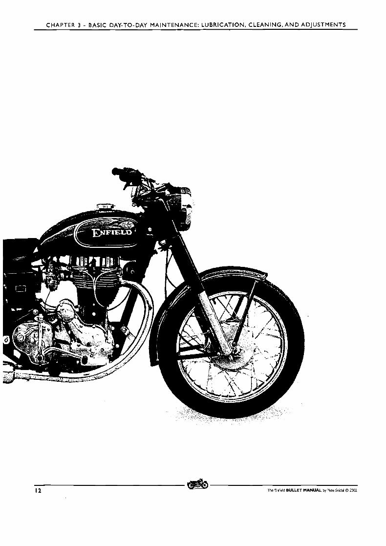
CHAPTER 3 - BASIC DAY-TO-DAY MAINTENANCE: LUBRICATION, CLEANING,AND ADJUSTMENTS
12 The Enfield BULLET MANUAL by Pete Snidal O 2002
CHAPTER 3 - BASIC DAY-TO-DAY MAINTENANCE: LUBRICATION, CLEANING, AND ADJUSTMENTS
CHAPTER 3 - BASIC DAY-TO-DAY MAINTENANCE: Lubrication, Cleaning, and Adjustments
I. CLEANING I
A clean motorcycle is a happy motorcycle! As well as the obvious benefits of pride of ownership and maintenance of
resale value, there is a very good reason for cleaning your motorcycle almost after every ride: - Vibration: this can bring
about loosening of fastenings, cracking or breakage of fittings, and misadjustments which become most apparent as
you go around the nooks and crannies of your machine with a brush and rag, cleaning and inspecting. You may be
surprised at the things you notice as you clean your bike - oil seepage becomes apparent before it becomes a major
problem, for example. Loose nuts or cracked fittings are much more easily remedied before they fail completely.
It is often a help to start by brushing it down with kerosene, washing solvent, or diesel fuel, followed by soapy water,
hot if possible, and rinsing carefully with hose or bucket. If water is in short supply, you can use a squirt bottle. Some owners mix a little diesel fuel in with the soapy water and do a "one-shot" washing - the diesel provides a corrosion inhibitor for the otherwise unprotected aluminum parts, of which the Bullet has plenty.
BUFFING: it is also helpful to polish the aluminum and even chrome parts. Automotive cut polish is good for aluminum,
but should be followed by waxing or diesel fuel. Mixtures of wax and polish, such as Turtle WaxTM are very good,
for paint, chrome, and aluminum.
As you clean the motorcycle, develop the habit of looking carefully at the fasteners, brackets, mounting points for
mudguard/fenders, etc. Look for cracks, loose nuts and bolts, and oil seepage. It's a good idea to follow up regularly
with spanner/wrenches, checking the tightness of your fasteners.
You may be surprised at how much better your mount runs after a decent bath!
2. LUBRICATION
Lubrication should be paid attention to as regularly as washing, and particularly after washing. Control cables, both at the end junctions of inner and outer cables, and particularly where the end nipples fit into the control levers (clutch
and front brake.) As for the throttle cable, pull the outer down from the tw i s t grip, and put a drop or two of oil on
the inner cable. Ditto for the front brake and clutch.
Oil levels should also be checked regularly. The engine oil level should be checked each time before starting the
motorcycle. Do this by unscrewing the oil filler cap, at the right side of the engine behind the timing cover, and noting
the oil level on the dipstick. If your level isn't betwe n the lines, this will be due to one of two reasons: Wet-Sumping,
or actual shortage of oil in the system.
e Wet-Sumping This is the name given to the condition in which a quantity of oil has leaked internally from the oil reservoir into the
sump, or bottom of the engine crankcase. The Bullet has a "Dry Sump" lubrication system, which means that a second oil pump, called the "scavenge pump," is used to move oil which has been through the engine parts, from the sump
The Enfield BULLET MANUAL by Pete Snidal O 2002 13
CHAPTER 3 - BASIC DAY-TO-DAY MAINTENANCE: LUBRICATION, CLEANING, A N D ADJUSTMENTS
back to the oil tank during operation. In some conditions, since the level in the separate but integrally-cast oil tank is
higher than the sump, oil may have migrated into the sump. For this reason, there is a separate sump drain at the
bottom of the crankcase unit - the forward one; the rearward one is the drain for the tank itself.
Wet-sumping is generally due t o the machine having been left for a period of time with the crankshaft/flywheel assembly in a position in which the Big End journal crankpin is at the bottom. (ie, the piston is at, or close to, BDC - Bottom Dead Center.) This will sometimes allow oil to be siphoned from the tank through the one-way valving of the
pressure-side oil pump and down into the big end, from where it will naturally leak through the clearance provided
and accumulate in the crankcase. If you experience a sudden decrease in tank oil level after having left the machine
parked for a period of time, this may be the situation. To check, clean the area around the FRONT drain plug under
the engine unit, place a clean drip pan under it, and remove the plug. Once any oil has run out, replace the drain plug.
Any oil which has drained may be poured back into the tank where it belongs, then check the oil level with the dipstick once again.
Excessive oil in the sump at start-up will evidence itself by huge quantities of blue smoke exiting out the exhaust pipe on startup, until the scavenge pump can catch up with the oil balance.
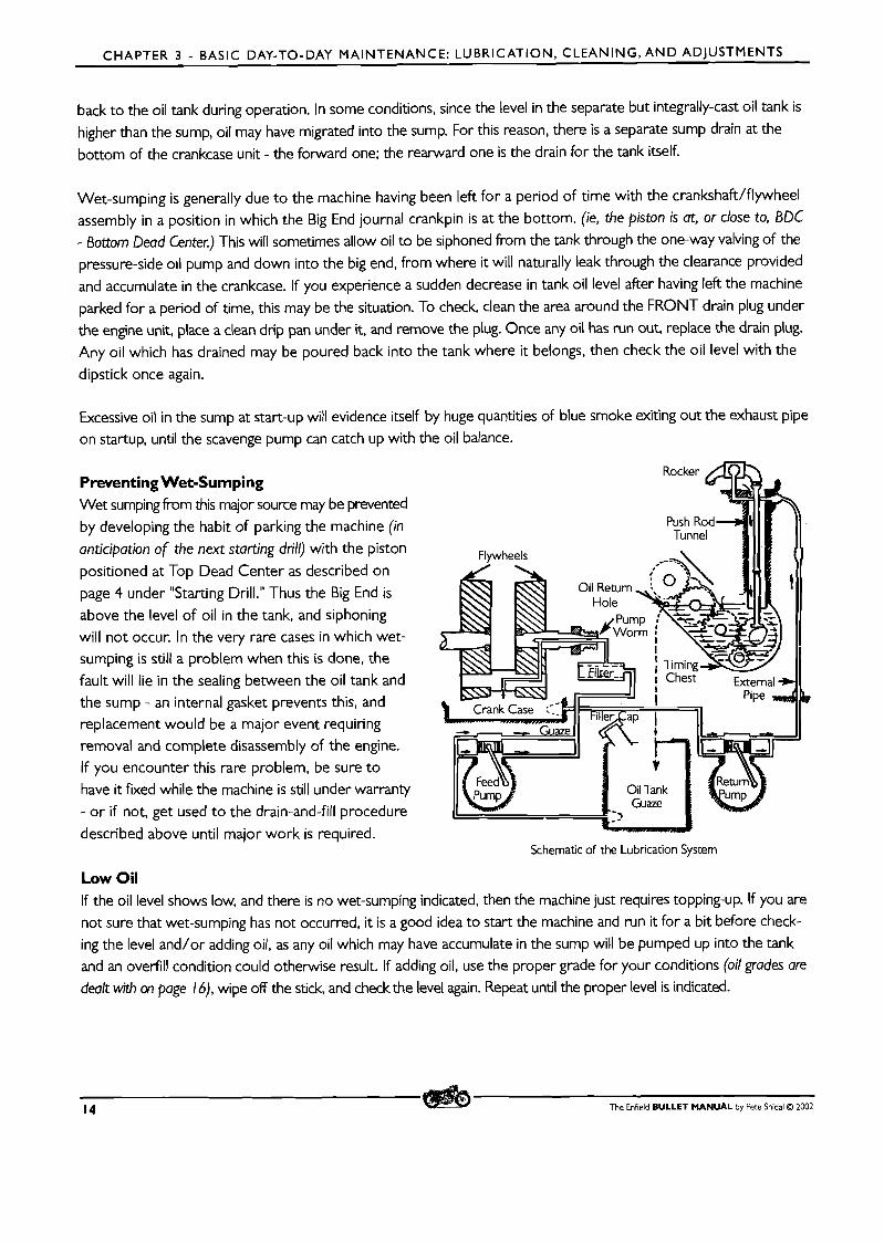
Rocker Preventing Wet-Sumping Wet sumping from this major source may be prevented
by developing the habit of parking the machine (in Push Rod- Tunnel
anticipation of the next starting drill) with the piston Flywheels positioned at Top Dead Center as described on
page 4 under "Starting Drill." Thus the Big End is above the level of oil in the tank, and siphoning will not occur. In the very rare cases in which wet- sumping is still a problem when this is done, the - fault will lie in the sealing between the oil tank and the sump - an internal gasket prevents this, and Crank Case -. replacement would be a major event requiring I
removal and complete disassembly of the engine.
If you encounter this rare problem, be sure t o have it fixed while the machine is still under warranty
- o r if not, get used t o the drain-and-fill procedure
described above until major work is required. Schematic of the Lubrication System
Low Oil If the oil level shows low, and there is no wet-sumping indicated, then the machine just requires topping-up. If you are
not sure that wet-sumping has not occurred, it is a good idea to start the machine and run it for a bit before check- ing the level and/or adding oil, as any oil which may have accumulate in the sump will be pumped up into the tank and an overfill condition could otherwise result. If adding oil, use the proper grade for your conditions (oil grades ore
dealt with on page 16), wipe off the stick, and check the level again. Repeat until the proper level is indicated.
14 The Enfield BULLET MANUAL by Pere Snidal O 2002

CHAPTER 3 - BASIC DAY-TO-DAY MAINTENANCE: LUBRICATION, CLEANING, AND ADJUSTMENTS
Also check the gearbox oil level occasionally - the gearbox will not consume oil as can the engine; oil will only disappear
from here by leakage, which will be apparent on the ground or pavement where you park the bike, as well as on the underside. Still, check your gearbox oil regularly - there is an oil level plug at the front or rear of the inner gearbox
cover, about two inches up from the bottom. To check the level, remove the filler plug, at the top of the gearbox on the
kickstarter side, and the level plug. Add some gear oil (SAE 90) to the gearbox until it drips at the oil level plug hole.
Although SAE9O gear oil is a much more appropriate gearbox lubricant, the Indian Enfield is shipped with a amalgam
of grease in the gearbox. This appears to be due to the fact that SAE9O will leak through the outer mainshaft bearing,
which is located inside the outer gearbox cover. This bearing may easily be replaced with a sealed unit, which will not pass oil. Many owners chose to make this modification, in the interest of better lubrication by changing over to SAE9O.
My experience with the British models has always been that they have no trouble holding SAE9O gear oil, and my
only conclusion is that at some point this choice of lube was made because they were having trouble with gearbox
leaks. I would add SAE 10-30 to the gearbox and drain regularly (every 5 hours of operation) until the drained goop
became fairly lightweight, then fill to proper level with SAE9O. The drain plug is at the bottom of the inner gearbox
cover. This recommendation is made after having read much discussion on the royalenfield yahoogroup - a number of
members have reported following this procedure with no trouble with oil leaks, and improved shifting (gearchanging.)
See Chapter 9 on gearbox work for more information.
The last place which needs regular level checks is the primary case. The primary drive chain and clutch both require a proper supply of clean oil to work and last properly. There is, unfortunately, no level plug on the primary chaincase,
nor is there a drain plug - draining is accomplished simply by unscrewing the central holding nut, and allowing the oil
to run out into a preferably long drainpan.
The filler plug is at the top, on the inner cover, about halfway from front to rear - about the rear of the cylinder barrel.
Initial level checking may be done by using a piece of wire or an old spoke - insert it all the way down around the
primary chain to the bottom of the case, and ensure that there is a level of around 2"/5cm at all times. Once you have
drained and refilled, check the level and calibrate your "dipstick" more closely. Keep it on hand for checking regularly.
Top up with SAE 20W40, or with Type F Automatic Transmission Fluid. Capacity is about 420ml.
Whenever you have the primary filler plug open, you should take the opportunity to check the primary chain tension.
Don't do it with the engine running - the fast-moving chain will almost certainly damage your finger beyond repair.
But with the engine stationary, you want to feel about I /4"/6mm of freedom of up/down slack on the top run of the primary chain. Using the decompression lever, kick the engine around a few times and check in different places,
as some eccentricity in the sprockets etc. can be expected. If adjustment is required, you'll have to drain the case
and remove the cover. See the chapter on chain adjustments.
The Enfield BULLET MANUAL by Pete Snidal O 2002 15
CHAPTER 3 - BASIC DAY-TO-DAY MAINTENANCE: LUBRICATION, CLEANING, AND ADJUSTMENTS
CHANGING OILS
I. Engine Since it is constantly being polluted by combustion byproducts and wear metals, the engine oil must be changed much more often than the others. Every 2000 miles/3200 km for a run-in engine is about right. More often if your miles
are in short trips. Factory recommendation is for SAE50 non-detergent motor oil. A lot of users report good results
with synthetic oils and/or multi-grades. Let your conscience be your guide, but remember that you want SAD0 final viscosity when hot - such as is claimed for SAE20W-50. For colder climates, a top viscosity of SAE 40 when warm is
recommended, using straight grade SAE 40 or SAE 15W-40.
As mentioned earlier, the Bullet's dry-sump system involves two oil pumps, the first drawing oil from the oil tank (this is cast integrally with the engine's crankcase, or sump, but they are e~clusive of one another), and running it through the
felt-element filter to the big-end/connecting rod journal. The oil passing through the big-end bearing is then thrown around the sump, lubricating the cylinder under the piston, and the bearing supporting the crankpins on each side of
the flywheel assembly, finally accumulating in the bottom of the crankcase - the sump.
From the sump, it is collected through a filter screen by suction from the second pump, the scavenge pump, and sent to the rocker arm bearings at the top of the cylinder head. Passing through these rocker blocks, it runs down
the pushrod tubes to the timing chest (the inside of the timing cover), where it lubricates the timing gears and oil pump(s) worm drive. The gears work it up to the upper ones, which funnel it into a hole in the back of the timing
case back into the oil tank.
It will be seen that there are a number of places in which the circulating oil accumulates, namely the oil tank, the
sump, the oil filter housing, and the bottom of the timing chest, although the latter holds so little oil it is hardly of
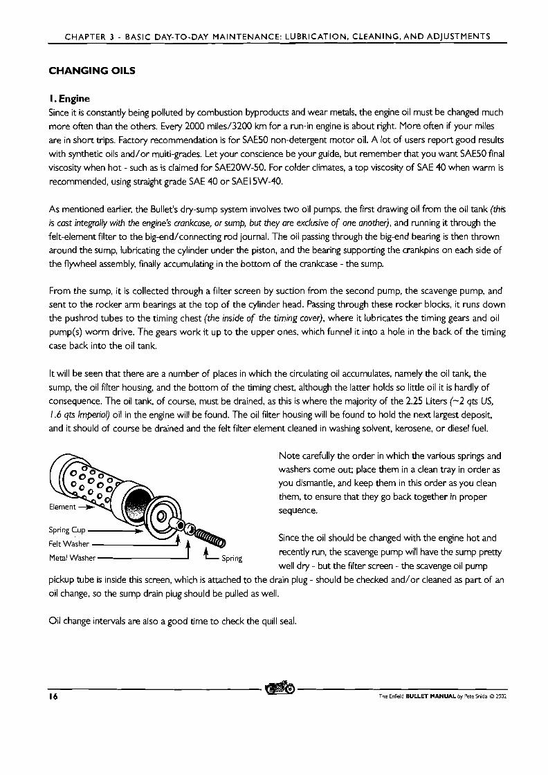
consequence. The oil tank, of course, must be drained, as this is where the majority of the 2.25 Liters (-2 qts US, 1.6 qts Imperial) oil in the engine will be found. The oil filter housing will be found to hold the next largest deposit, and it should of course be drained and the felt filter element cleaned in washing solvent, kerosene, or diesel fuel.
Metal ~ a s h e r A L Spring
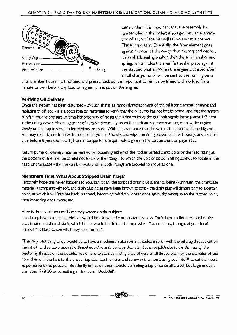
Note carefully the order in which the various springs and washen come out; place them in a clean tray in order as you dismantle, and keep them in this order as you clean
them, to ensure that they go back together in proper sequence.
Since the oil should be changed with the engine hot and
recently run, the scavenge pump will have the sump p r e q well dry - but the filter screen - the scavenge oil pump
pickup tube is inside this screen, which is attached to the drain plug - should be checked and/or cleaned as part of an
oil change, so the sump drain plug should be pulled as well.
Oil change intervals are also a good time to check the quill seal.
16 The Enfield BULLET MANUAL by Pete Snidal O ZOO2
CHAPTER 3 - BASIC DAY-TO-DAY MAINTENANCE: LUBRICATION, C L E A N I N G , A N D ADJUSTMENTS
Checking the Quill-style Oil Pressure Feed Bush The Bullet is unique in feeding oil pressure through a hollow feed bolt into the rotating right-side crankpin via a hollow
quill, sealed by a cork gland situated in a recessed internal shoulder in the end of the crankpin. Although this system
has proven to be very reliable over many years, the cork is somewhat primitive - most manufacturers of British
machines began using modern spring-and-lip neoprene seals by the end of the '60's - it is a potential weak point, and
should be monitored on a regular basis. Oil change intervals are a good time to check the quill bushing.
This may be accomplished by removing the quill feed bolt - in the center of the timing cover, above the oil filter
housing - be sure to have a catch tray to receive the oil which will drain from the timing cover cavity. Once this is
done, examination may be done with a strong light of the cork quill seal in the end of the crankpin. If there is any
sign of cracking, missing sections, etc., or if it appears to have a fairly loose fit around the quill, it should be replaced.
The knowledgeable Bullet owner will order replacement cork seals ten at a time, and always have one or two of the
better ones he has soaking in clean oil, ready for replacing. Replacement is covered on page 59.
Oil Change Intervals Your first oil change on a new engine should be at the 3-500 mile mark. The wear curve is initially very steep, and the oil will get quite polluted with wear metals and removed machining abrasives. You will want to change your oil filter
element for the first two or three changes as well, so be sure to have a couple of oil filter elements on hand in advance
of your first change - spare drain plug washers couldn't hurt, either. Obtain both of these from your Enfield dealer.
You'll also, of course, need a couple of litres of SAE50 motor oil. This is not common from automotive sources, but
in a pinch, try your local airport. 50wt oil is commonly used in aircraft, as are multi-grades of similar viscosity. Your
second oil change should be in the 4-700 mile range (100 miles-160 Km), and you should change the filter at that
point as well. The third at 1000, and after that every 2000. The third filter at the 2000 change, and after that every
second change. You can track the efficacy of filter changes by carefully washing your filter in clean washing solvent,
and looking in a strong light for metallic particles in the washings. Your observations may colour your decision over
how often to wash and/or change the element.
To drain the oil, with the machine on the center stand, locate the oil tank and sump drain plugs - a mirror on the floor is useful here. Find the correct size wrench/spanner - you want one which surrounds the plug completely - a box end or socket. Place a drain pan under the Sump plug - at the front right side on the bottom. Unscrew the plug (it's upside down, remember, so it will seem like tightening when viewed from the top) and allow any oil in the
sump to drain into the pan. Clean the filter screen in washing solvent and shake or blow it out. Ensure that the
gasket is still in good condition, wipe the plug and crankcase gasket face clean with a clean rag, and replace the
plug. Then do the same for the oil tank plug about 4"/ I OOcm behind the and to the left of the one you just
replaced. This will bring out the majority of the oil - about 1.5L. Clean and replace the plug as above. In both
cases, be careful to ensure that the mesh housing aligns properly with the pickup tube inside the hole, and the
mesh isn't twisted by the replacement. Ensure that the sealing washers are in good condition.
Now for the oil filter housing. Place the drain pan under the front of the oil filter housing - the round lump about
10"/25cm long, 2"/5cm in diameter. Loosen the nut at the front of the housing, and gently tap the side of the cover
with the side of a suitable spanner/wrench or small hammer/persuader. When the seal breaks, the oil will begin to
drain into the pan. When it's drained, carefully dismantle the innards, placing them (for the first time) on an old newspaper in the order of dismantling. Clean them one at a time in washing solvent and set them back in the
The Enfield BULLET MANUAL by Pete Snidal O 2002 17
CHAPTER 3 - BASIC DAY-TO-DAY MAINTENANCE: LUBRICATION. CLEANING,AND ADIUSTMENTS
same order - it is important that the assembly be
reassembled in this order; if you get lost, an examina-
tion of each of the bits will tell you what is correct.
This is important: Essentially, the filter element goes
against the rear of the cavity, then the stepped washer,
it's small felt sealing washer, then the small washer and
spring, which holds the small felt seal in place against
Metal Washer the stepped washer. When the engine is started after
an oil change, no oil will be sent to the running parts
until the filter housing is first filled and pressurized, so it is important to run it slowly and with no load for a
minute or two before any load or higher rpm is put on the engine.
Verifying Oil Delivery Once the system has been disturbed - by such things as removal/replacement of the oil filter element, draining and replacing of oil, etc. - it is a good idea on restarting to vedy that the oil pump has not lost its prime, and that the system
is in fact making pressure. A time-honored way of doing this is first to leave the quill bolt slightly loose (about 1 /2 turn) in the timing cover. Have a spanner of suitable size ready, as well as a clean rag, then start up, running the engine slowly until oil squirts out under obvious pressure. With this assurance that the system is delivering to the big end, you may then tighten it up with the spanner you had handy, and wipe the timing cover, oil filter housing, and exhaust pipe before it gets too hot. Tightening torque for the quill bolt is given in the torque chart on page 162.
Return pump oil delivery may be verified by loosening either of the rocker oilfeed banjo bolts or the feed fitting at
the bottom of the line. Be careful not to allow the fitting into which the bolt or bottom fitting screws to rotate in the
head or crankcase - the line can be twisted off if both fittings are allowed to move as one.
Nightmare Time: What About Stripped Drain Plugs? I sincerely hope this never happens to you, but it can: the stripped drain plug scenario. Being Aluminum, the crankcase
material is comparatively soft, and drain plug holes have been known to strip - the drain plug will tighten only to a certain point, at which it will "ratchet back" a thread, becoming relatively looser once again, tightening up to the ratchet point, then loosening once more, etc.
Here is the text of an email I recently wrote on the subject: "To do a job with a suitable Helicoil would be a long and complicated process. You'd have to find a Helicoil of the proper size and thread pitch, which I think would be difficult to impossible. You could try, though, at your local HelicoilTM dealer, to see what they recommend".
"The very best thing to do would be to have a machinist make you a threaded insert - with the oil plug threads cut on
the inside, and suitable-pitch (the thread would have to be large diameter, but small pitch due to the thinness of the
crankcase) threads on the outside. You'd have to start by finding a tap of very small thread pitch for the diameter of the hole, then drill the hole to the proper tap size, tap the hole, and screw in the insert, using Loc-TiteTM to set the insert
as permanently as possible. But the fly in this ointment would be finding a tap of so small a pitch but large enough diameter. 7/8-20 or something of the sort. Doubtful".
18 The Enfield BULLET MANUAL by Pete Snidal O 2002
CHAPTER 3 - BASIC DAY-TO-DAY MAINTENANCE: LUBRICATION, CLEANING, AND ADJUSTMENTS
"Now, what I would do comes to mind: NAPA and such autoparts stores sell replacement self-tapping drain plugs in
various sizes. Although these are intended primarily for steel oilpans in auto apps, I once used one to solve the same
problem in a Twin-Cam MGA many y'ars ago, Billy! It had a cast-aluminum oil pan, very similar to the Bullet setup.
Take your old plug down there, and try to find one just a bit larger - they usually have a "splits" in the threads, so
they can be enlarged a bit as well, so you can custom-expand it until you feel it 's getting a decent bite into what's left
of your current threads. Be really careful with this - you've only got one chance".
"First, check the plug carefully against your new one, and ensure that it is not too long - it could interfere with the
pick-up tube which extends down into the filter screen on the old plug. This must not be allowed to happen. You should also try to devise a way to attach your old filter screen - or fabricate a new one - to the new plug, although
you may just have to run without a screen".
"Since the new oilplug is actually cutting threads for itself, there will be some shavings produced, so you will have to make
at least one cutting pass, and remove the plug to clean out shavings before final installation. For the first pass, do not tighten
really hard - just snug it up about halfway between your previous 'slipping' torque and fully tight. Then remove the plug
and carefully examine the new threads inside the hole. If these look as if you could improve them by expanding the plug
slightly, do this and then make another pass. It will be a help to lubricate the plug threads with fresh engine oil to aid in cutting".
"Once you've done the best you can to make your new plug a good thread fit into your case, remove it one last
time, and carefully clean all signs of shavings out of the hole. Reach up into the inside of the tank/case with a
finger, and ensure that the cavity is completely clean of shavings - just one of these in an oil pump can have dis-
astrous consequences. A disadvantage of this alternative is that your new oilplug will not have a pickup screen attached - unless you can somehow solder your old screen onto the new plug".
"Once this fix is effected, it would be a good idea to disturb the new, tight plug as little as possible. If it's the crankcase
plug, you should leave it alone once you get one in there tightly - be sure to take full precautions against wetsumping
(see page 13 in this Chapter) in future. If the oil tank, well, you could consider buying an "oilsucker" of some kind. A
handpump model or even one that attaches to an electric drill - marine supply shops have these for sure, for changing
oil in inboard marine apps. Then you could just leave the plug in place and suck the oil out for changes. The self-tapping
plugs don't always carve themselves the best factory-spec threads, and once in there, should not be assumed to be just
like the original in terms of usability. Of course, if you have managed to attach a filter screen to your new plug, you should
take it out periodically to ensure that the screen isn't becoming plugged, but for routine oil changes, I'd be inclined to use
alternative draining methods - if the new plug became stripped also, it's unlikely you'll be able to go yet another oversize."
The next time the engine is apart, the case should be taken to a competent welder, and the hole welded over, and
re-drilled and tapped to the proper thread size for a new original plug."
2. Gearbox
As mentioned above, Indian Enfields appear to be shipped with mostly grease in the gearbox. As there are many small
spaces, such as between gears and shafts, shafts and bushings, etc., which grease would have to be too thick to penetrate
properly, this is mysterious to this writer. The only explanation that comes to mind is a policy change which was intended
to deal with leaks. Personally, I'd take my chances with leaks, and switch to SAE9O gear oil ASAP The procedure is
The Enfield BULLET MANUAL by Pete Snidal Q 2002 19
CHAPTER 3 - SECOND-GUESSING THE DEALER: N E W MOTORCYCLE PRE-DELIVERY PREPARATION
describe above. Once you've found the combination that works best, compromising heavinesdleak resistance with "lightness," if SAE9O may be considered "light," you won't have to change the gearbox often. Breakin, of course, will,
as with the engine, show an initial high wear curve, but changing at 5000 mile intervals, once the oil thickness has been
sorted out, should be completely adequate. Examination of drained oil in a bright light will be the best indicator of
how often gearbox oil need be changed - it wants changing within the interval which displays wear metals in the drained oil. There is virtually no combustion pollution or high-heat breakdown as in the engine.
3. Primary Case
The same applies to the primary case. Drain the oil into a clean pan and examine it for wear metal and bits of clutch debris. If none is present, it is satisfactory just to replace it with the same oil. I prefer to use ATF, since its colour
helps to identify signs of burning from clutch slippage, and it is formulated for an application almost identical to use in a motorcycle primary chain/clutch case.
GENERAL CHASSIS LUBRICATION
Any two surfaces that move against one another require lubrication at their interface. This includes cables and control
levers, wheel bearings, brake cam shafts, speedometer cable, and of course the hydraulic front forks, which, being hydraulic, are self-lubricated if properly filled. Procedures are as follows:
Cables and Levers: Lubrication of these components should be maintained as detailed above. Pay particular attention to the interface between the cable-end nipples where they fit into the control levers.
Wheel Bearings Each of the wheel hubs contains a ball bearing on each side, through which the axle runs. Periodically, the wheels
should be removed, and the dust seals and bearings pressed out and the bearings packed. An ideal interval for this task is during brake shoe replacement This will be covered in the later chapter on brake service.
Brake Cam Shafts These are the shafts which run through the brake backing plates, front and rear, which pass on the torque imparted
on the actuation lever by tension of the control cable or foot lever. A spot or two of oil should be applied to the
outside of the shaft each time the machine is washed. Beware of over lubrication - oil on the surface of the brake
shoes will result in poor brake performance, possibly including chattering on application. In extreme conditions of dust or mud, it may be necessary periodically to dismantle the wheel and polish the shaft to eliminate any rust or gum which impedes proper return action of the shaft by the brake return spring, resulting in brake drag and poor feel. This is a good time also to check the condition of your brake shoes.
Speedometer Cable The speedometer cable needs to be lubricated, but excessive lubrication must be avoided, as oil or grease can work its way up the cable into the speedometer mechanism itself, and cause havoc - wildly swinging speedometer needle, for instance, or even the needle going to full reading as soon as the machine begins to move. For this reason, it is recom-
mended that the inner cable be removed periodically, wiped clean with a clean dry rag, and lubricated with a few
20 The Enfield BULLET MANUAL by Pete Snidal O 2002
CHAPTER 3 - SECOND-GUESSING THE DEALER: N E W MOTORCYCLE PRE-DELIVERY PREPARATION
drops of motor oil every 6 in./ 15 cm as it is replaced into the outer housing. Remove the cable by unscrewing the
outer cable from the base of the speedometer housing (you must remove the headlight assembly from the f i n t of the
casquette to gain access), and withdraw the inner cable with a pair of pliers. As it is being removed is a good time to wipe it
clean by drawing it through the rag, changing the position of the rag every interval described above. If the inner cable is
particularly dirty, it should first be washed in kerosene, diesel fuel, or washing solvent before being replaced.
Front Forks: The front forks, being hydraulic, require that a certain amount of hydraulic fluid be present for proper operation.
This also provides lubrication of the sliders around the main tubes. The proper procedure for draining, flushing, and refilling is covered later in this manual.
Rear Shocks The rear shocks, although also hydraulic, are sealed units and require no maintenance other than replacement when
necessary. Fortunately, this is a rare requirement - they last for many thousands of kilometers.
This covers the lubrication requirements of the Bullet
SECOND-GUESSING T H E DEALER: N E W MOTORCYCLE PRE-DELIVERY PREPARATION
The Enfield Motorcycle is not a high-volume item in the industry. Consequently, dealers are few and far between,
and often they and their staff are not completely acquainted with the idiosyncrasies of this rare bird. Let's face it - India is basically a third-world country, and their high-tech (If that it may be called) exports, such as the Enfield
Bullet, are an entirely different kettle of fish than most other motorcycles. For these reasons, it is wise for the new
Bullet owner, on taking delivery, to ensure that proper "pre-delivery" preparation has been carried out. As well, as the machine does i ts first few thousand miles, it will often change rapidly in certain adjustments and settings,
so the wise new owner will stay on top of these.
First, all of the lubrication and adjustments covered in Chapters 3 and 4 should be gone over before using the
machine - Ignition timing and carburetor adjustment are especially important. As well, there may be a few other
small problems showing up, mostly in the electrical system and fuel delivery areas.
ELECTRICAL SYSTEM
Check the operation of all aspects of the electrical system - lights, horn, and charging system. The primary reason
for problems with these components will be bad grounds - only half of the electrical path, or "circuit," for any device
is provided by wires; the other half of the connection is made through the chassis - frame, mudguard, etc. The connection point to/from the chassis/frame for any component is provided by a wire connected between that
component and the frame. If the connection has become rusty, or not enough/no paint was removed prior to
the connection being made, high electrical resistance may be encountered, which will affect operation of the light or other device concerned.
The Enfield BULLET MANUAL by Pete Snidal O 2002 2 1
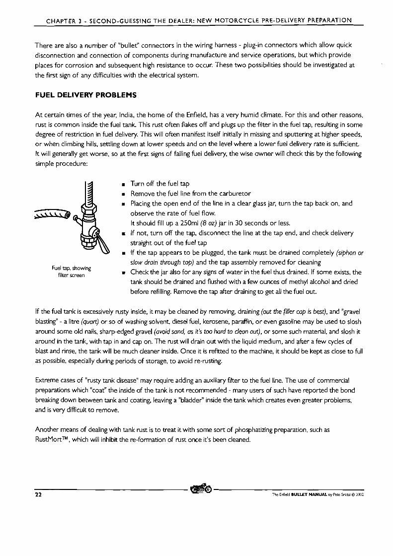
CHAPTER 3 - SECOND-GUESSING T H E DEALER: N E W MOTORCYCLE PRE-DELIVERY PREPARATION
There are also a number of "bullet" connectors in the wiring harness - plug-in connectors which allow quick
disconnection and connection of components during manufacture and service operations, but which provide
places for corrosion and subsequent high resistance to occur. These two possibilities should be investigated at
the first sign of any difficulties with the electrical system.
FUEL DELIVERY PROBLEMS
At certain times of the year, India, the home of the Enfield, has a very humid climate. For this and other reasons, rust is common inside the fuel tank. This rust often flakes off and plugs up the filter in the fuel tap, resulting in some degree of restriction in fuel delivery. This will often manifest itself initially in missing and sputtering at higher speeds, or when climbing hills, sealing down at lower speeds and on the level where a lower fuel delivery rate is sufficient. It will generally get worse, so at the first signs of failing fuel delivery, the wise owner will check this by the following
simple procedure:
Turn off the fuel tap
Remove the fuel line from the carburetor B Placing the open end of the line in a clear glass jar, turn the tap back on, and
observe the rate of fuel flow.
It should fill up a 250ml (8 oz) jar in 30 seconds or less. If not, turn off the tap, disconnect the line at the tap end, and check delivery straight out of the fuel tap
B If the tap appears to be plugged, the tank must be drained completely (siphon or slow drain through tap) and the tap assembly removed for cleaning
Fuel tap, showing filter screen D Check the jar also for any signs of water in the fuel thus drained. If some exists, the
tank should be drained and flushed with a few ounces of methyl alcohol and dried
before refilling. Remove the tap after draining to get all the fuel out.
If the fuel tank is excessively rusty inside, it may be cleaned by removing, draining (out the filler cap is best), and "gravel
blasting" - a litre (quart) or so of washing solvent, diesel fuel, kerosene, paraffin, or even gasoline may be used to slosh
around some old nails, sharp-edged gravel (avoid sand, as it's too hard to clean out), or some such material, and slosh it
around in the tank, with tap in and cap on. The rust will drain out with the liquid medium, and after a few cycles of blast and rinse, the tank will be much cleaner inside. Once it is refitted to the machine, it should be kept as close to full as possible, especially during periods of storage, to avoid re-rusting.
k r e m e cases of "rusty tank disease" may require adding an auxiliary filter to the fuel line. The use of commercial
preparations which "coat" the inside of the tank is not recommended - many users of such have reported the bond
breaking down between tank and coating, leaving a "bladder" inside the tank which crezttes even greater problems, and is very difficult to remove.
Another means of dealing with tank rust is to treat it with some sort of phosphatizing preparation, such as
RustMortTM, which will inhibit the re-formation of rust once it's been cleaned.
22 The Enfield BULLET MANUAL by Pete Snidal O 2002
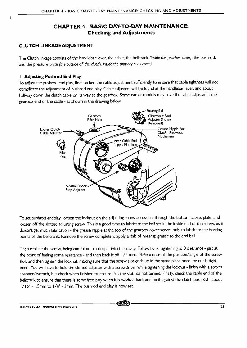
CHAPTER 4 - BASIC DAY-TO-DAY MAINTENANCE: CHECKING A N D ADJUSTMENTS
l
CHAPTER 4 - BASIC DAY-TO-DAY MAINTENANCE: Checking and Adjustments
CLUTCH LINKAGE ADJUSTMENT
The Clutch linkage consists of the handlebar lever, the cable, the bellcrank (inside the gearbox cover), the pushrod,
and the pressure plate (the outside of the clutch, inside the primary chaincase.)
I. Adjusting Pushrod End Play To adjust the pushrod end play, f irst slacken the cable adjustment sufficiently to ensure that cable tightness will not
complicate the adjustment of pushrod end play, Cable adjusters will be found at the handlebar lever, and about
halfway down the clutch cable on its way to the gearbox. Some earlier models may have the cable adjuster at the
gearbox end of the cable - as shown in the drawing below.
Bearing Ball
Lowe~ Cable
Gearbox Filler Hole
Adjuster - Clutch -47 (Throwout Rod Adjuster Shown
4, Removed) Grease Nipple For clutch Throwout Mechanism
Inner Cable End
To set pushrod endplay, loosen the locknut on the adjusting screw accessible through the bottom access plate, and
loosen off the slotted adjusting screw. This is a good time to lubricate the ball set in the inside end of the screw, as it
doesn't get much lubrication - the grease nipple at the top of the gearbox cover serves only to lubricate the bearing
points of the bellcrank. Remove the screw completely, apply a dab of hi-temp grease to the end ball.
Then replace the screw, being careful not to drop it into the cavity. Follow by re-tightening to 0 clearance - just at
the point of feeling some resistance - and then back it off 1 /4 turn. Make a note of the position/angle of the screw
slot, and then tighten the locknut, making sure that the screw slot ends up in the same place once the nut is tight-
ened. You will have to hold the slotted adjuster with a screwdriver while tightening the locknut - finish with a socket
spanner/wrench, but check when finished to ensure that the slot has not turned. Finally, check the cable end of the
bellcrank to ensure that there is some free play when it is worked back and forth against the clutch pushrod - about
I / 16" - 1.5mm to 1 /8" - 3mm. The pushrod end play is now set.
The Enfield BULLET MANUAL by Pete Snidal O 2002 23
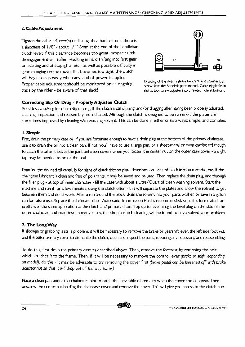
CHAPTER 4 - BASIC DAY-TO-DAY MAINTENANCE: CHECKING A N D ADJUSTMENTS
2. Cable Adjustment
Tighten the cable adjuster(s) until snug, then back off until there is a slackness of 1 /8" - about I /4"-6mm at the end of the handlebar
clutch lever. If this clearance becomes too great, proper clutch disengagement will suffer, resulting in hard shifting into first gear 17 20
on starting and at stoplights, etc., as well as possible difficulty in gear changing on the move. If it becomes too tight, the clutch will begin to slip easily when any kind of power is applied.
Drawing of the clutch release bellcrank and adjuster ball Proper cable adjustment should be monitored on an ongoing screw from the Redditch parts manual. Cable nipple fits in basis by the rider - be aware of that slack!
. . slot at top; screw adjuster into threaded hole at bottom.
Correcting Slip O r Drag - Properly Adjusted Clutch Road test, checking for clutch slip or drag. If the clutch is still slipping, and/or dragging after having been properly adjusted, cleaning, inspection and reassembly are indicated. Although the clutch is designed to be run in oil, the plates are sometimes improved by cleaning with washing solvent. This can be done in either of two ways: simple, and complex.
I. Simple First, drain the primary case oil. If you are fortunate enough to have a drain plug at the bottom of the primary chaincase,
use it to drain the oil into a clean pan. If not, you'll have to use a large pan, or a sheet-metal or even cardboard trough to catch the oil as it leaves the joint between covers when you loosen the center nut on the outer case cover - a slight
tap may be needed to break the seal.
Examine the drained oil carefully for signs of clutch friction plate deterioration - bits of black friction material, etc. If the chaincase lubricant is clean and free of pollutants, it may be saved and re-used. Then replace the drain plug, and through the filler plug - at top of inner chaincase - fill the case with about a Litre/Quart of clean washing solvent. Start the
machine and run it for a few minutes, using the clutch often - this will separate the plates and allow the solvent to get between them and do its work. After a run around the block, drain the solvent into your parts washer, or save in a gallon can for future use. Replace the chaincase lube - Automatic Transmission Fluid is recommended, since it is formulated for pretty well the same application as the clutch and primary chain. Top up to level using the level plug on the side of the outer chaincase and road test. In many cases, this simple clutch cleaning will be found to have solved your problem.
2. The Long Way If slippage or grabbing is still a problem, it will be necessary to remove the brake or gearshift lever, the left side footrest, and the outer primary cover to dismantle the clutch, clean and inspect the parts, replacing any necessary, and reassembling.
To do this, f i rs t drain the primary case as described above. Then, remove the footrest by removing the bolt which attaches it to the frame. Then, if it will be necessary t o remove the control lever (brake or shifi, depending
on model), do this - it may be advisable to try removing the cover f irst (brake pedal can be loosened of with brake adjuster nut so that it will drop out of the way some.)
Place a clean pan under the chaincase joint to catch the inevitable oil remains when the cover comes loose. Then unscrew the center nut holding the chaincase cover and remove the cover. This will give you access to the clutch hub.
24 The Enfield BULLET MANUAL by Pete Snidal O 2002
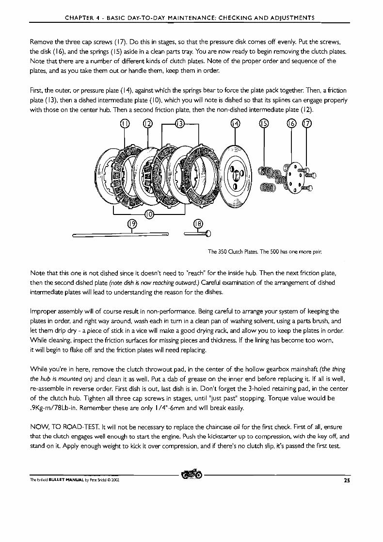
CHAPTER 4 - BASIC DAY-TO-DAY MAINTENANCE: CHECKING A N D ADJUSTMENTS
Remove the three cap screws ( 1 7). Do this in stages, so that the pressure disk comes off evenly. Put the screws,
the disk ( 1 6), and the springs ( 1 5) aside in a clean parts tray. You are now ready to begin removing the clutch plates.
Note that there are a number of different kinds of clutch plates. Note of the proper order and sequence of the plates, and as you take them out or handle them, keep them in order.
First, the outer, or pressure plate ( 1 4), against which the springs bear to force the plate pack together. Then, a friction
plate ( 1 3), then a dished intermediate plate (IO), which you will note is dished so that its splines can engage properly
with those on the center hub. Then a second friction plate, then the non-dished intermediate plate ( 1 2).
The 350 Clutch Plates. The 500 has one more pair.
Note that this one is not dished since it doesn't need to "reach" for the inside hub. Then the next friction plate,
then the second dished plate (note dish is now reaching outward.) Careful examination of the arrangement of dished intermediate plates will lead to understanding the reason for the dishes.
Improper assembly will of course result in non-performance. Being careful to arrange your system of keeping the
plates in order, and right way around, wash each in turn in a clean pan of washing solvent, using a parts brush, and
let them drip dry - a piece of stick in a vice will make a good drying rack, and allow you to keep the plates in order.
While cleaning, inspect the friction surfaces for missing pieces and thickness. If the lining has become too worn,
it will begin to flake off and the friction plates will need replacing.
While you're in here, remove the clutch throwout pad, in the center of the hollow gearbox mainshaft (the thing
the hub is mounted on) and clean it as well. Put a dab of grease on the inner end before replacing it. If all is well,
re-assemble in reverse order. First dish is out, last dish is in. Don't forget the 3-holed retaining pad, in the center
of the clutch hub. Tighten all three cap screws in stages, until "just past" stopping. Torque value would be
.9Kg-m/78Lb-in. Remember these are only I /4"-6mm and will break easily.
NOW, TO ROAD-TEST. I t will not be necessary to replace the chaincase oil for the first check. First of all, ensure that the clutch engages well enough to start the engine. Push the kickstarter up to compression, with the key off, and
stand on it. Apply enough weight to kick it over compression, and if there's no clutch slip, it's passed the first test.
The Enfield BULLET MANUAL by Pete Snidal O 2002 25
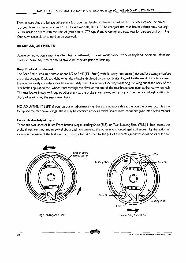
CHAPTER 4 - BASIC DAY-TO-DAY MAINTENANCE: CHECKING AND ADJUSTMENTS
Then, ensure that the linkage adjustment is proper, as detailed in the early part of this section. Replace the cover,
footpeg, lever as necessary, and on LF brake models, BE SURE to readjust the rear brake before road-testing!
Fill chaincase to specs with the lube of your choice (ATF type F: my favourite) and road test for slippage and grabbing.
Your new, clean clutch should serve you well!
BRAKE ADJUSTMENTS
Before setting out on a machine after chain adjustment, o r brake work, wheel work of any kind, or on an unfamiliar
machine, brake adjustment should always be checked prior to starting.
Rear Brake Adjustment The Rear Brake Pedal must move about 1 /2 to 3/4" ( 1 2- 1 8mm) with full weight on board (rider and/or passenger) before the brake engages. If it is too tight, when the wheel is displaced on bumps, brake drag will be the result If it is too loose,
the obvious safety considerations take effect. Adjustment is accomplished by tightening the wing nut at the back of the
rear brake application rod, where it fits through the clevis at the end of the rear brake cam lever, at the rear wheel hub.
The rear brake linkage will require adjustment as the brake shoes wear, and also any time the rear wheel position is
changed in adjusting the rear drive chain.
N O ADJUSTMENT LEFT? If you run out of adjustment - ie, there are no more threads left on the brake rod, it is time to replace the rear brake linings. These may be obtained at your Enfield Dealer, Instructions are given later in this manual.
Front Brake Adjustment There are two kinds of Bullet Front brakes: Single Leading Shoe (SLS), or Twin Leading Shoe CrLS.) In both cases, the
brake shoes are mounted to swivel about a pin on one end, the other end is forced against the drum by the action of
a cam on the inside of the brake actuator shaft, which is turned by the pull of the cable against the clevis on its outer end.
Single Leading Shoe Brake Irl
Twin Leading Shoe Brake
26 The Enfield BULLET MANUAL by Pete Snidal O 2002
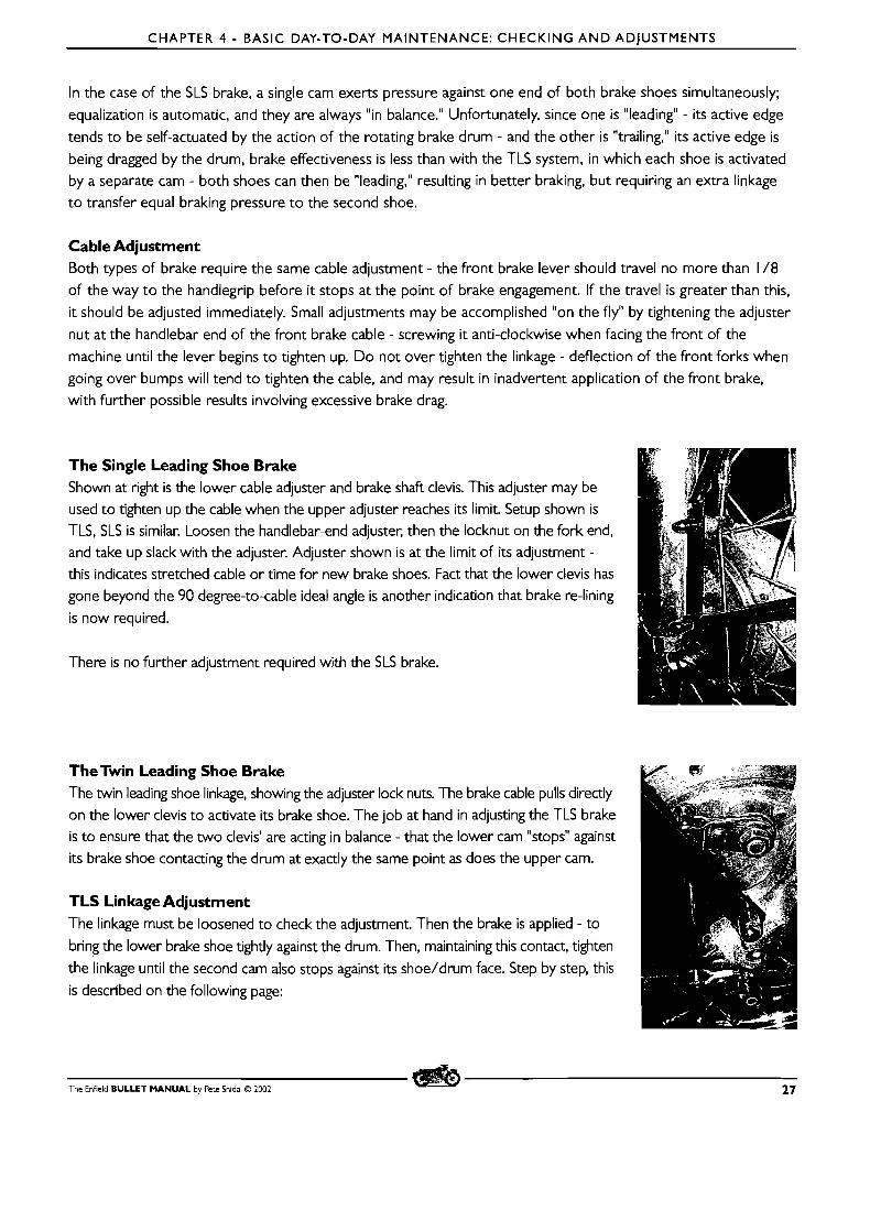
CHAPTER 4 - BASIC DAY-TO-DAY MAINTENANCE: CHECKING A N D ADJUSTMENTS
In the case of the SLS brake, a single cam exerts pressure against one end of both brake shoes simultaneously;
equalization is automatic, and they are always "in balance." Unfortunately, since one is "leading" - its active edge
tends to be self-actuated by the action of the rotating brake drum - and the other is "trailing," its active edge is
being dragged by the drum, brake effectiveness is less than with the TLS system, in which each shoe is activated
by a separate cam - both shoes can then be "leading," resulting in better braking, but requiring an extra linkage
to transfer equal braking pressure to the second shoe.
Cable Adjustment Both types of brake require the same cable adjustment - the front brake lever should travel no more than 1 /8 of the way to the handlegrip before it stops at the point of brake engagement. If the travel is greater than this,
it should be adjusted immediately. Small adjustments may be accomplished "on the fly" by tightening the adjuster
nut at the handlebar end of the front brake cable - screwing it anti-clockwise when facing the front of the
machine until the lever begins to tighten up. Do not over tighten the linkage - deflection of the front forks when
going over bumps will tend to tighten the cable, and may result in inadvertent application of the front brake,
with further possible results involving excessive brake drag.
The Single Leading Shoe Brake Shown at right is the lower cable adjuster and brake shaft clevis. This adjuster may be
used to tighten up the cable when the upper adjuster reaches its limit. Setup shown is TLS, SLS is similar. Loosen the handlebar-end adjuster, then the locknut on the fork end, and take up slack with the adjuster. Adjuster shown is at the limit of its adjustment -
this indicates stretched cable or time for new brake shoes. Fact that the lower clevis has
gone beyond the 90 degree-to-cable ideal angle is another indication that brake re-lining
is now required.
There is no further adjustment required with the SLS brake.
The Twin Leading Shoe Brake The twin leading shoe linkage, showing the adjuster lock nuts. The brake cable pulls directly
on the lower clevis to activate its brake shoe. The job at hand in adjusting the TLS brake
is to ensure that the two clevis' are acting in balance - that the lower cam "stops" against
its brake shoe contacting the drum at exactly the same point as does the upper cam.
TLS Linkage Adjustment The linkage must be loosened to check the adjustment. Then the brake is applied - to
bring the lower brake shoe tightly against the drum. Then, maintaining this contact, tighten
the linkage until the second cam also stops against its shoe/drum face. Step by step, this
is described on the following page:
The Enfield BULLET MANUAL by Pete Snidal O 2002 27
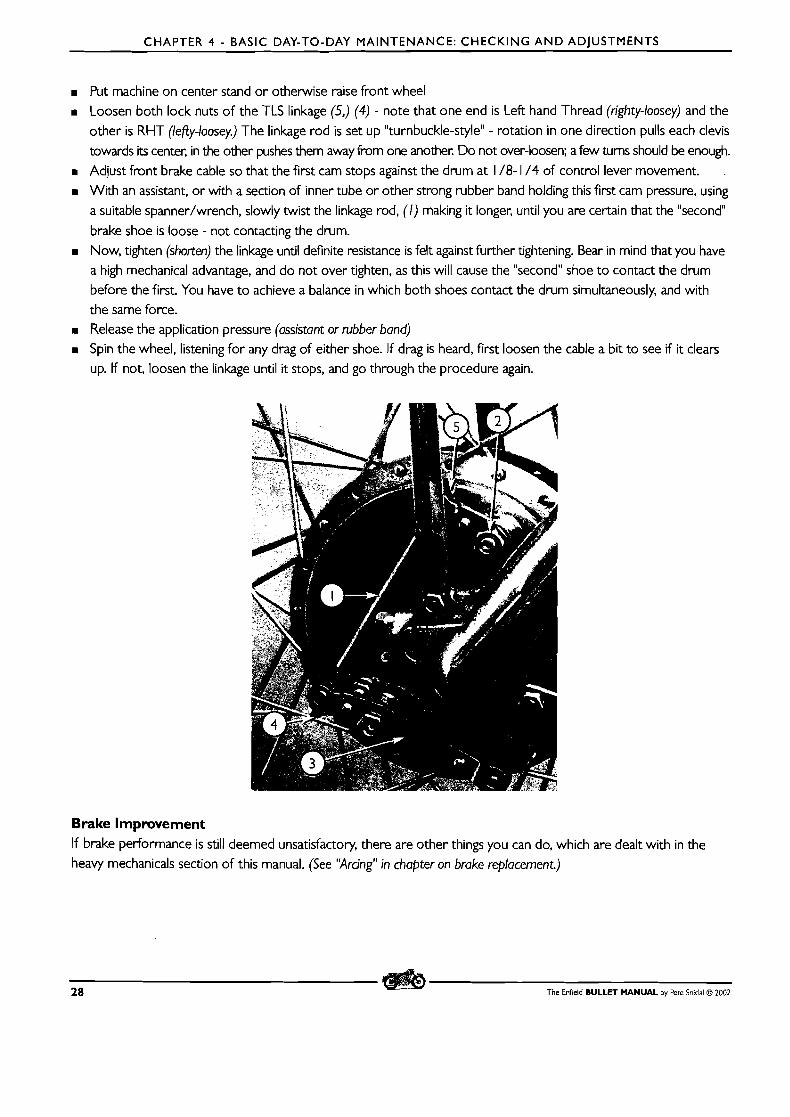
CHAPTER 4 - BASIC DAY-TO-DAY MAINTENANCE: CHECKING AND ADJUSTMENTS
m Put machine on center stand or otherwise raise front wheel Loosen both lock nuts of the TLS linkage (5,) (4) - note that one end is Left hand Thread (righty-loosey) and the
other is RHT (lefiy-loosey.) The linkage rod is set up "turnbuckle-style" - rotation in one direction pulls each clevis
towards its center, in the other pushes them away from one another. Do not over-loosen; a few turns should be enough. m Adjust front brake cable so that the first cam stops against the drum at 1 /8- 1 /4 of control lever movement. .
m With an assistant, or with a section of inner tube or other strong rubber band holding this first cam pressure, using
a suitable spanner/wrench, slowly twist the linkage rod, (I) making it longer, until you are certain that the "second
brake shoe is loose - not contacting the drum. Now, tighten (shorten) the linkage until definite resistance is felt against further tightening. Bear in mind that you have a high mechanical advantage, and do not over tighten, as this will cause the "second" shoe to contact the drum before the first. You have to achieve a balance in which both shoes contact the drum simultaneously, and with the same force. Release the application pressure (assistant or rubber band) Spin the wheel, listening for any drag of either shoe. If drag is heard, first loosen the cable a bit to see if it clears up. If not, loosen the linkage until it stops, and go through the procedure again.
Brake Improvement If brake performance is still deemed unsatisfactory, there are other things you can do, which are dealt with in the heavy mechanicals section of this manual. (See "Arcing" in chapter on brake replacement.)
28 The Enfield BULLET MANUAL by Pete Snidal O 2002
CHAPTER 4 - BASIC DAY-TO-DAY MAINTENANCE: CHECKING A N D ADJUSTMENTS
SPOKE TUNING
Your wheels are very finely-tuned tension structures. Each of the spokes must carry i ts share of the weight, and
a too-tight spoke will soon break. This can happen from the factory, or from the spokes around it loosening up
as the wheel "breaks in."
Consequently, although i t is far above the capacity of the average owner to build wheels, he should include
checking spoke tension as part of the regular maintenance. How to do it? Simple! - just tap each of the spokes
in each wheel with a spanner/wrench o r other like-sized piece of metal. The spokes will have a "ring" to them,
and the idea is to make sure that the ring doesn't degenerate to a "thunk" as the spokes loosen off during use.
Loose spokes may be tightened with a spanner on the spoke nipple. It may be good to put a drop of oil on each nipple occasionally, in anticipation of this necessity. Do not go too far at once; the spokes operate in concert with
one another, and good balance between them must be maintained. When tightening any spoke, look closely at
the design of the spoke pattern, and check the opposite-pulling spoke for tension as well. Try to stay on top of things, so that you never need to tighten any spoke more than 1 /8 to 1 /4 turn.
Check the wheels regularly for "run-out" - spin them and ensure that they don't wobble as they turn. If so, you'll
either have to work out how to re-tune the spokes, o r take the machine to a shop with a good reputation for
tuning wheels. It is an art! But don't forget that many a good wheel-builder can be found in bicycle shops as well!
Spokes Can Get Too Long! Also, remember that when you tighten up a spoke, i t will be screwed into the nipple, and therefore into the
inside of the wheel. It doesn't have to go very far before becoming dangerous to the inner tube - it can result in
a tire going flat quite quickly, or at best creating a slow leak. Be aware of this possibility, and if you find that any
spoke is taking more than a full turn over the course of your ownership, you should dismount the wheel and tire
and check the spoke ends - they may be filed off.
CHAINS - CHECKING AND ADJUSTMENTS
There are only two chains on the Bullet, both requiring periodic adjustment. The rear drive chain, running as it
does in the elements, and not being as overbuilt as the primary chain, requires more regular maintenance.
The Rear Chain CONDITION: worn chains are BAD economy!
I t is necessary to check the chain's condition regularly. As a chain wears, it "stretches," getting longer from end
to end due to the holes in the plates, in which the rollers run, elongating. This "stretch" is also evidenced from
center to center of each roller, and it will soon exceed the c-to-c tolerance level for the sprockets, with the
rollers beginning to ride up on the sprocket teeth. This will result in an extreme steepening of the sprocket wear
curve, resulting in hooked teeth and trashing of the sprockets. Since a pair of sprockets and the work required
to change them is in the order of tens of times the value of a new chain, it is only good insurance to change
chains in a timely fashion. Your chain should not require replacement for awhile - a number of adjustments will
be required first, but when you run out of adjustment, replace it for sure - don't be tempted to take out a link,
The Enfield BULLET MANUAL by Pete Snidal O 2002 29
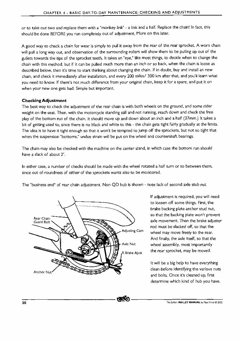
CHAPTER 4 - BASIC DAY-TO-DAY MAINTENANCE: CHECKING A N D ADJUSTMENTS
or to take out two and replace them with a "monkey link" - a link and a half. Replace the chain! In fact, this should be done BEFORE you run completely out of adjustment. More on this later.
A good way to check a chain for wear is simply to pull it away from the rear of the rear sprocket. A worn chain
will pull a long way out, and observation of the surrounding rollers will show them to be pulling up out of the
gullets towards the tips of the sprocket teeth. It takes an "eye," like most things, to decide when to change the
chain with this method, but if it can be pulled much more than an inch o r so back, when the chain is loose as described below, then it's time to start thinking about changing the chain. If in doubt, buy and install an new chain, and check it immediately after installation, and every 200 miles/ 300 km after that, and you'll learn what
you need to know. If there's not much difference from your original chain, keep it for a spare, and put it on when your new one gets bad. Simple but important.
Checking Adjustment The best way to check the adjustment of the rear chain is with both wheels on the ground, and some rider
weight on the seat. Then, with the motorcycle standing still and not running, reach down and check the free play of the bottom run of the chain. It should move up and down about an inch and a half (37mm.) I t takes a bit of getting used to, since there is no black and white to this - the chain gets tight fairly gradually at the limits. The idea is to have it tight enough so that it won't be tempted to jump off the sprockets, but not so tight that when the suspension "bottoms," undue strain will be put on the wheel and countershaft bearings.
The chain may also be checked with the machine on the center stand, in which case the bottom run should have a slack of about 2".
In either case, a number of checks should be made with the wheel rotated a half turn or so between them,
since out-of-roundness of either of the sprockets wants also to be monitored.
The "business end" of rear chain adjustment. Non-QD hub is shown - note lack of second axle stub nut
Guard Bolt \ m -.
Cam
y ust
If adjustment is required, you will need to loosen off some things. First, the brake backing plate anchor stud nut,
so that the backing plate won't prevent axle movement. Then the brake adjuster rod must be slacked off, so that the wheel may move freely to the rear. And finally, the axle itself, so that the
wheel assembly, most importantly
the rear sprocket, may be moved.
It will be a big help to have everything
clean before identifying the various nuts
and bolts. Once it's cleaned up, first
determine which kind of hub you have.
3 0 The Enfield BULLET MANUAL by Pete Snidal O 2002
CHAPTER 4 - BASIC DAY-TO-DAY MAINTENANCE: CHECKING A N D ADJUSTMENTS
There are two types of rear wheels - the QD (Quick-Detachable) and the regular. The QD is made so that the
brake and rear sprocket assembly may be left in place when the wheel is removed - they're held in place in the swingarm by a hollow "stub axle," with two nuts on the left side, and the regular full-width axle, with its bolt
head on the right. With the QD hub, the main axle nut, on the left side, is probably castellated, and "safetied"
by a cotter pin. Remove this pin, slack off the castellated nut, and then slack off the stub axle nut, the second
nut behind it, before attempting to move the wheel.
The regular wheel has only one nut on each side, with an axle that runs through both swing arms and the wheel/sprocket/brake assembly as a whole.
Then, whichever procedure you've had to follow so far, the wheel will be loose to slide in the swingarm
slots to adjust for proper chain tension.
Moving the Wheel Now to adjust the wheel position. The object is t o move the axle, usually to the rear to tighten the chain, so
that the wheel is far enough back to attain proper chain slack, and also in line with the motorcycle - it must be
aligned with the front wheel. Fortunately, this is most generally attainable by aligning the chain so that it runs true
on and off the front sprocket, but the wheel should be checked with a string line on your particular bike, to
ensure that this is sufficient - (we're assuming here that the countenhafi (front) sprocket is perpendicular to the
fore/afi axis of the motorcycle.)
There are adjusting cams on each end of the axle. Note that having both of these at the same angle is no guarantee that the wheel/sprocket are in linearity with the front sprocket - this must be checked by one of a variety of
methods. In any event, the cams help to hold the wheel tight against moving forward from chain tension, and
will allow you to move the wheel by tapping them around with a hammer and a punch (but don't use your socket
extension, be sure to use your genuine brass drift!) A time-honoured method is to kick the wheel sideways at the
rear, starting with the chain side, to get the chain "just about" tight enough, followed by re-setting the adjusting
cam on that side to hold the new setting. Then, kick the rear of the wheel to the left, from the right side, and
follow up with adjustment of the right side cam. Fine-tune for final adjustment, then, be sure to check for linearity:
One is the straight edge method. You can put a straight edge, such as a machinist's rule, or a thin piece of metal
flat bar, along the bottom of the sprocket, just inside the chain line. Adjust the wheel until the straight edge is
parallel to the bottom run of the chain for i ts entire length. The rear sprocket is now lined up with the chain, and
presumably the front sprocket. Then, run a piece of string along the lower side of the rear tire from as high a point as possible from front to rear. Continue with this run to the front of the front wheel, and ensure that the
four tire wall faces are in line with each other.
If you must compromise to get the chain and the wheels both running straight, then you must, but hopefully the
two methods will both show linearity. One will affect handling and steering, the other chain life. Both are important.
Once you have the proper slack, and the wheel assy. is straight, tighten up all the nuts again, and BE SURE TO
RE-ADJUST THE REAR BRAKE ROD! THIS IS IMPORTANT! In the case of the QD hub, tighten up the large
hub nut first, then the axle nut. If a regular hub (nuts on both sides of the axle) tighten the two nuts against each
other - the axle may turn as you get tight with either nut, so alternate tightening to get around this. In the case
The Enfield BULLET MANUAL by Pete Snidal O 2002 3 1
CHAPTER 4 - BASIC DAY-TO-DAY MAINTENANCE: CHECKING A N D ADJUSTMENTS
of the QD hub, the axle bolt head may be held with a tommy bar through the hole, or if there is none, with a
regular spanner/wrench. Be sure t o finish with tightening the anchor stud nut!
IT IS IMPORTANT TO READJUST YOUR BRAKE ROD - it's no fun t o ride off with your new chain and find
out you forgot the first time you need t o stop. Stopping with front brake only is often a harrowing experience!
REPLACING A CHAIN
There are a couple of little tricks t o make changing a chain easier. First, since your new chain will be "shorter," and you'll therefore have to adjust the wheel position anyway, begin by loosening off all the bolts for adjustment as described above. Move the cam adjusters around t o full slack, and then kick the wheel at the rear t o move it as far forward as i t will go. Be careful not to kick the bike off the center stand! Then rotate the wheel until the master link is at the rear of the sprocket. Then break the link by prying off the spring retainer clip, and pushing the main plate pins through the auxiliary plate. Do not pull out the chain!
Then unpack your new chain. Lay it out on the ground behind the motorcycle, in line with the sprockets. Using your old
master link join it at the top to the old chain. Then, pulling on the old chain at the bottom, pull the new chain around through the front sprocket until you have the fresh chain on the rear sprocket, ready for the new master link. Install the
new master link, with the open end of the spring clip pointing against the direction of forward rotation of the chain.
IVow, adjust the chain as described above, and you're away! DON'T FORGET THE BRAKE ROD ADJUSTMENT!
The Primary Chain The primary chain, running as it does in an oil bath and dustproof environment, rarely requires replacement, and seldom even adjustment. But it should be checked regularly, until you get a "feel" for how often it can be expected t o change i ts setting. Check the slack through the primary case filler hole, at the top center of the primary case. NEVER ATTEMPT TO CHECK PRIMARY CHAIN TENSION WITH ENGINE RUNNING! With engine off, use
a bent piece of wire or an old spoke to check for about 1 /4 inch (6 mm) of slack. As with the rear chain, rotate the chain by using the kickstarter with compression release and check the slack a number of times.
If adjustment is required, you'll have to drain the case and remove the case cover. Since there is no drain plug in most Bullet chaincases, you'll need a long enough drain pan to catch all the dripping oil when the seal between the case
covers breaks after releasing the center nut on the outer chaincase. Clean the bottom of the chaincase thoroughly with a rag, brush and solvent, etc, since if the oil is unpolluted, you will be able to re-use it after adjusting the chain.
Remove any footpegs, brake pedals, etc. that are in the way - this will vary with model. Then unscrew the center
nut in the primary cover and the cover will easily come off - there is a neoprene 0-ring for sealing, so no glue
will be holding anything. Drain the oil into a suitable clean container, and completely remove the outer cover once the oil has stopped dripping.
3 2 The Enfield BULLET MANUAL by Pete Snidal O ZOO2
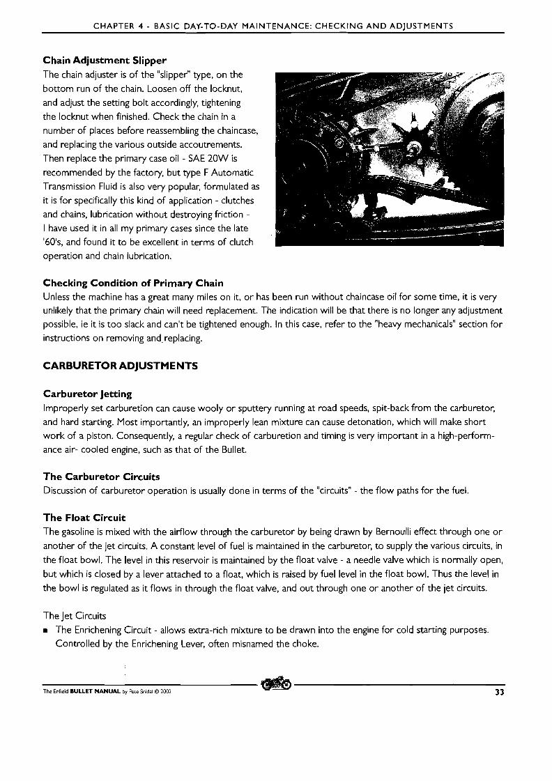
CHAPTER 4 - BASIC DAY-TO-DAY MAINTENANCE: CHECKING AND ADJUSTMENTS
Chain Adjustment Slipper The chain adjuster is of the "slipper" type, on the
bottom run of the chain. Loosen off the locknut, and adjust the setting bolt accordingly, tightening
the locknut when finished. Check the chain in a number of places before reassembling the chaincase,
and replacing the various outside accoutrements.
Then replace the primary case oil - SAE 20W is
recommended by the factory, but type F Automatic
Transmission Fluid is also very popular, formulated as it is for specifically this kind of application - clutches
and chains, lubrication without destroying friction - I have used it in all my primary cases since the late '601s, and found it to be excellent in terms of clutch
operation and chain lubrication.
Checking Condition of Primary Chain Unless the machine has a great many miles on it, or has been run without chaincase oil for some time, it is very unlikely that the primary chain will need replacement. The indication will be that there is no longer any adjustment
possible, ie it is too slack and can't be tightened enough. In this case, refer to the "heavy mechanicals" section for instructions on removing and replacing.
CARBURETOR ADJUSTMENTS
Carburetor Jetting Improperly set carburetion can cause wooly or sputtery running at road speeds, spit-back from the carburetor,
and hard starting. Most importantly, an improperly lean mixture can cause detonation, which will make short work of a piston. Consequently, a regular check of carburetion and timing is very important in a high-perform-
ance air- cooled engine, such as that of the Bullet.
The Carburetor Circuits Discussion of carburetor operation is usually done in terms of the "circuits" - the flow paths for the fuel.
The Float Circuit The gasoline is mixed with the airflow through the carburetor by being drawn by Bernoulli effect through one or
another of the jet circuits. A constant level of fuel is maintained in the carburetor, to supply the various circuits, in
the float bowl. The level in this reservoir is maintained by the float valve - a needle valve which is normally open,
but which is closed by a lever attached to a float, which is raised by fuel level in the float bowl. Thus the level in
the bowl is regulated as it flows in through the float valve, and out through one or another of the jet circuits.
The Jet Circuits m The Enrichening Circuit - allows extra-rich mixture to be drawn into the engine for cold starting purposes.
Controlled by the Enrichening Lever, often misnamed the choke.
The Enfield BULLET MANUAL by Pete Snidal O 2002 33
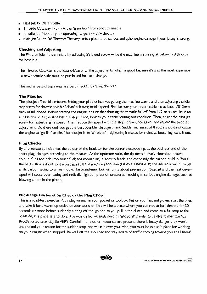
CHAPTER 4 - BASIC DAY-TO-DAY MAINTENANCE: CHECKING AND ADJUSTMENTS
m Pilot Jet: 0- 1 /8 Throttle B Throttle Cutaway 1 /8- 1 /4: the "transition" from pilot to needle
B Needle Jet: Most of your operating range: 1 /4-3/4 throttle B Main Jet: 3/4 to Full Throttle: The very easiest place to do serious and quick engine damage if your jetting is wrong.
Checking and Adjusting The Pilot, or Idle jet is checked by adjusting it's bleed screw while the machine is running at below 1 /8 throttle
for best idle.
The Throttle Cutaway is the least critical of all the adjustments, which is good because it's also the most expensive
- a new throttle slide must be purchased for each change.
The midrange and top range are best checked by "plug checks":
The Pilot Jet The pilot jet affects idle mixture. Setting your pilot jet involves getting the machine warm, and then adjusting the idle stop screw for slowest possible "clean" tick-over, or idle speed. First, be sure your throttle cable has at least I /8-3mm slack at full closed. Before starting the engine, ensure that shutting the throttle full off from 1 / 2 or so results in an audible "clack" as the slide hits the stop. If not, look to your cable routing and condition. Then, adjust the pilot jet screw for fastest engine speed. Then reduce the speed with the stop screw once again, and repeat the pilot jet adjustment. Do these until you get the best possible idle adjustment. Sudden increases of throttle should not cause
the engine t o "go flat" or die. The pilot jet is an "air bleed" - tightening it makes for richness, loosening leans it out.
Plug Checks By a fortunate coincidence, the colour of the insulator for the center electrode tip, at the business end of the spark plug, changes according to the mixture. A t the optimum ratio, the tip turns a lovely chocolate-brown
colour. If it's too rich (too much fuel; not enough air) it goes to black, and eventually the carbon buildup "fouls" the plug - shorts it out so it won't spark. If the mixture's too lean (HEAVY DANGER!) the insulator will burn off all its carbon, going to white - looks like brand-new, but will bring about pre-ignition (pinging) and the heat devel- oped will cause overheating and radically high compression pressures, resulting in serious engine damage, such as blowing a hole in the piston.
Mid-Range Carburetion Check - the Plug Chop This is a road-test exercise. Put a plug wrench in your pocket or toolbox. Put on your hat and gloves, start the bike, and take it for a warm-up cruise to your test site. This will be a place where you can ride at half throttle for 30
seconds o r more before suddenly cutting off the ignition as you pull in the clutch and come to a full stop at the
roadside, in a place safe to do a little work. (You will likely need a slight uphill in order to be able to maintain half
throttle for 30 seconds.) Be VERY Careful! If any other motorists are present, there is heavy danger they won't understand your reason for the sudden stop, and will run over you. Also, you must be in a safe place for working
on your engine when stopped. Be well off the shoulder and stay aware of traffic coming toward you at all times!
3 4 The Enfield BULLET MANUAL by Pete Snidal O 2002
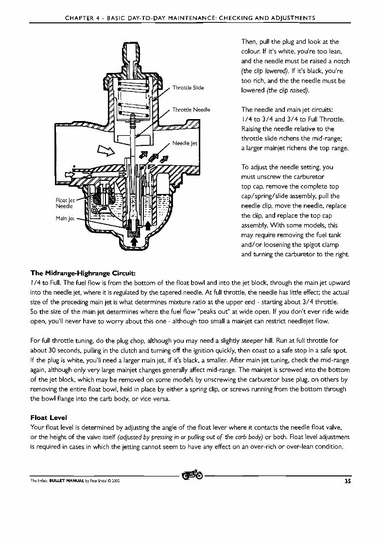
CHAPTER 4 - BASIC DAY-TO-DAY MAINTENANCE: CHECKING A N D ADJUSTMENTS
Then, pull the plug and look at the
colour. If it's white, you're too lean,
and the needle must be raised a notch
(the clip lowered). If it's black, you're
too rich, and the the needle must be
lowered (the clip raised).
The needle and main jet circuits:
1 /4 to 3/4 and 3/4 to Full Throttle. Raising the needle relative to the
throttle slide richens the mid-range; a larger mainjet richens the top range.
To adjust the needle setting, you
must unscrew the carburetor
top cap, remove the complete top
cap/spring/slide assembly, pull the
needle clip, move the needle, replace
the clip, and replace the top cap
assembly. With some models, this
may require removing the fuel tank
and/or loosening the spigot clamp and turning the carburetor to the right.
The Midrange-Highrange Circuit: 1 /4 to Full. The fuel flow is from the bottom of the float bowl and into the jet block, through the main jet upward
into the needle jet, where it is regulated by the tapered needle. At full throttle, the needle has little effect; the actual
size of the preceding main jet is what determines mixture ratio at the upper end - starting about 3/4 throttle.
So the size of the main jet determines where the fuel flow "peaks out" at wide open. If you don't ever ride wide
open, you'll never have to worry about this one - although too small a mainjet can restrict needlejet flow.
For full throttle tuning, do the plug chop, although you may need a slightly steeper hill. Run at full throttle for
about 30 seconds, pulling in the clutch and turning off the ignition quickly, then coast to a safe stop in a safe spot.
If the plug is white, you'll need a larger main jet, if it's black, a smaller. After main jet tuning, check the mid-range
again, although only very large mainjet changes generally affect mid-range. The mainjet is screwed into the bottom
of the jet block, which may be removed on some models by unscrewing the carburetor base plug, on others by
removing the entire float bowl, held in place by either a spring clip, or screws running from the bottom through the bowl flange into the carb body, or vice-versa.
Float Level Your float level is determined by adjusting the angle of the float lever where it contacts the needle float valve, o r the height of the valve itself (adjusted by pressing in or pulling out of the carb body) or both. Float level adjustment
is required in cases in which the jetting cannot seem to have any effect on an over-rich or over-lean condition.
The Enfield BULLET MANUAL by Pete Snidal O 2002 3 5

CHAPTER 4 - BASIC DAY-TO-DAY MAINTENANCE: CHECKING A N D ADJUSTMENTS
Bad Flooding Sometimes a carburetor will pass fuel out its overflow tube from the instant the fuel tap is turned on. This condition can be brought about by dirt fouling the float needle, or an excessively worn needle valve or seat. First, remove the float
bowl and carefully take out the float lever hinge pin, and then remove the float and lever. With a suitable container,
such as an empty tuna can, under the carburetor, open the fuel tap and allow some fuel to run through the unimpeded float valve. This should wash out any dirt particles. If dirt is obviously a problem, the fuel tank may have to be removed and cleaned. Test the float valve closure after reassembling the float and lever into the carburetor.
CHASSIS ADJUSTMENTS
There are a number of adjustments and maintenance procedures necessary t o keep the general chassis in tune
on your Bullet. These may be divided into the following categories:
Front Forks A. LUBRICATION Lubrication of the fork sliders is taken care of by the hydraulic oil in the fork legs themselves. There should be about 200cc of hydraulic oil, SAE20-20W, or ATF in each fork leg. If there are no signs of leakage, and no indications
of "bottoming" - a heavy clang when the front wheel is deflected suddenly by such things as speed bumps - there is probably nothing amiss with fork oil level. To check level, remove the cap screw at the top of each
tube (in the casquette casting), and insert a piece of rod about 2 feet - 60cm long down the hole t o use as a dipstick. If you feel around, you'll feel an obstruction partway down the tube, and the oil level should cover this obstruction (the top of the damper rod, or "fork spring stud).
B. STEERING HEAD ADJUSTMENT
Steering head adjustment, although seldom necessary, is easily
checked. The front forks are mounted in a fork head at the front
of the frame, in adjustable ball bearings. If the bearing cups are not sufficiently tight, the front end will be allowed t o move in
unconventional ways, affecting handling in a negative manner.
To check for looseness, simply apply front brake while straddling
the machine, and rock it fore and aft, paying attention t o the area
of the fork head. Any looseness will immediately become apparent.
To adjust the steering head bearing clearance, first loosen off the two fork tube clamp bolts ( I ) at the bottom of the casquette. Then loosen off the adjuster clamp bolt (2) at the top rear. Now you will be able to screw down the top crown adjuster nut (3). Run it down until it's tight, then back a bit until the front end
turns freely in the fork head. (Machine on center stand with front
wheel of the floor.) Re-tighten the clamp bolts when finished.
36 The Enfield BULLET MANUAL by Pete Snidal O 2002
CHAPTER 4 - BASIC DAY-TO-DAY MAINTENANCE: CHECKING A N D ADJUSTMENTS
Tire Pressure Although most riders prefer slight variations in tire pressures, depending on user variables, the pressures
recommended are fairly consistently around 30 psi. The off-road rider may prefer to drop his pressures a bit for
better traction, and slightly lower pressure - say 25 psi - may be more appropriate for a lighter rider, Two-up
riding will require the full 30psi. Tire pressures should be checked after an hour's riding or so - the tire and i ts air
will heat up on riding, and this is the important pressure. If you check them cold first, you'll have an idea of what the cold pressure equivalent will be.
Wheel Alignment Proper alignment of the wheels with one another is very important. If they are not completely parallel, the rear wheel will be trying to steer around the front one, and although the rider will unconsciously compensate for a
lot of variation, it will radically affect cornering and braking. A good way to check is with a straight edge or tight string between front and rear tire walls. The straight edge must contact all four walls - front front, rear front,
front rear, and rear rear - simultaneously.
A second less accurate method is to observe the top run of the rear chain as it rolls over the front sprocket with the rear wheel in the air and being turned, o r by placing a straight edge on the bottom of the rear sprocket and seeing that i t runs parallel to the rear chain. But the long straight method above is best.
Lubrication There are some lubrication points on the general chassis. Rear brake lever, the control levers, the swingarm
bushing grease nipples, if any - all must be maintained in lubricated condition. So also should the chain.
Chain lubrication is dealt with under chain adjustments.
Controls The controls must also be maintained in proper adjustment. Brake controls are very important, as are clutch
and throttle controls. Ensure that the cables and their nipples in the control levers are properly lubricated, and inspect your cables regularly for signs of fraying in the inner cable, and of deterioration of the outer coating of
the outer cables. A t the first sign of cable deterioration, particularly fraying of the inner, they should be replaced. If the owner feels ambivalent about replacing an "almost-good" cable, he should replace it anyway, and relegate the "almost-good" one to a place in the toolbox, or taped under the seat, as a spare. Most owners will agree
upon thinking about trying to ride home with a broken throttle o r clutch cable.
Fittings Finally, the chassis should be examined regularly for signs of cracking o r deterioration of the various fittings -
mudguards, lights, control levers, etc. Fasteners should be checked regularly for proper tightness - if you can
get a half-turn on a fastener (being of coune careful not to over-tighten), you know you've just saved yourself
some grief down the road.
The Enfield BULLET MANUAL by Pete Snidal O 2002 3 7
CHAPTER 4 - BASIC DAY-TO-DAY MAINTENANCE: CHECKING AND ADJUSTMENTS
CHECKINGYOUR IGNITION TIMING
Motorcycle engines, being small, air-cooled, and often high-output, are a little more critical when it comes to ignition timing than their automotive counterparts. This means you want t o be sure that your timing is within
spec at all times. Just a few minutes running at the wrong settings can blow a hole in your piston or burn your
exhaust valve and its seat badly. Consequently, even the new and not particularly mechanically inclined rider
must quickly learn the signs of bad timing.
The Signs I . EXCESSIVE ADVANCE: Every rider of an air-cooled engine first must learn t o recognize the sound of detonation, o r "ping." I t is unmistakable once you've heard i t a few times - i t sounds like little marbles are rattling around in the top of your engine, gets louder as you open the throttle, and comes on less with throttle as the engine speed (rpm) increases. I t is the sound of the "flame front" of burning gasses meeting the piston while it is still on its way
upward. This meeting of two opposing forces is not only noisy; it is very hard on the machinery. Extra heat is developed, and this, coupled with the excess pressure, soon punches a hole in the piston crown. Although i ts
consequences can be very expensive t o fix, detonation can easily and inexpensively be prevented merely by educating your ear to the sound of ping, and listening for it at all times. It is a subtle sound compared to the thump and chatter already present, but easily picked out from the background if it occurs.
2. RETARDATION:
There is, however no sound attributed to retarded timing - the flame front has to chase the piston down the cylinder because the spark occurred too late. This will result in an excess of unburnt fuel being present when
the exhaust valve opens, and this fuel will continue t o burn in the exhaust system, as well as polluting the atmosphere. The exhaust note sounds a little "flat," but other than that, the only signs will be overheating of the cylinder head and exhaust pipe - the chrome will become burn blue for a much longer distance than is
normal (normal = - I 0 in. - 4 cm), but by the time this irreversible indicator comes into effect, it's likely you've done some damage to the exhaust valve and/or i ts seat in the cylinder head.
How does ignition timing come to change? First of all, by wearing of the ignition points. As the rubbing block which opens them against the point spring wears, they come to open less and later, which will retard the ignition
timing. If properly lubricated, this rubbing block wear will necessitate re-adjusting the ignition, or contact breaker, points very seldom - perhaps ever 3000 mi - 4800 km or so. The new rider is well advised to check the point
gap at 1000 mile intervals, however, and to adjust them if necessary.
Checking Point Gap Remove the cover of the contact breaker (behind the cylinder barrel - accessible from the lefl side of the machine). Using the compression release and the kick starter, rotate the engine until the points have opened - they will be
observed to open and close as the engine rotates. Once the points have reached their maximum opening, first examine them for signs of pitting or burning. With your screwdriver, pry the moving point away from the stationary one and check for burning or pitting of either of the point surfaces. (If there are any such signs, the points must be removed and dressed with a fine file, or replaced.
3 8 The Enfield BULLET MANUAL by Pete Snidal O 2002
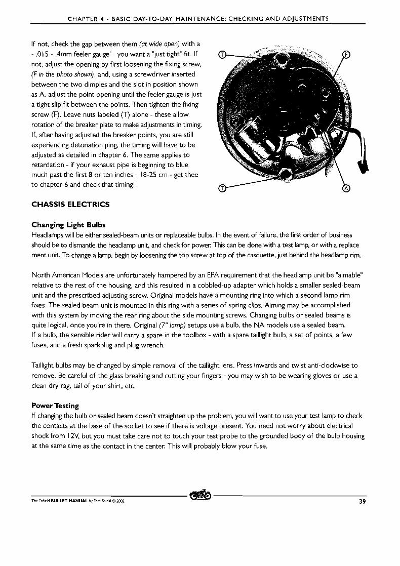
CHAPTER 4 - BASIC DAY-TO-DAY MAINTENANCE: CHECKING A N D ADJUSTMENTS
If not, check the gap between them (at wide open) with a
- .O 15 - ,4mm feeler gauge' - you want a "just tight" fit. If
not, adjust the opening by first loosening the fixing screw,
(F in the photo shown), and, using a screwdriver inserted
between the two dimples and the slot in position shown
as A, adjust the point opening until the feeler gauge is just
a tight slip fit between the points. Then tighten the fixing
screw (F). Leave nuts labeled (T) alone - these allow
rotation of the breaker plate to make adjustments in timing.
If, after having adjusted the breaker points, you are still
experiencing detonation ping, the timing will have to be
adjusted as detailed in chapter 6. The same applies to retardation - if your exhaust pipe is beginning to blue much past the first 8 or ten inches - 18-25 cm - get thee
to chapter 6 and check that timing!
CHASSIS ELECTRICS
Changing Light Bulbs Headlamps will be either sealed-beam units or replaceable bulbs. In the event of failure, the first order of business
should be to dismantle the headlamp unit, and check for power. This can be done with a test lamp, or with a replace-
ment unit. To change a lamp, begin by loosening the top screw at top of the casquette, just behind the headlamp rim.
North American IYodels are unfortunately hampered by an EPA requirement that the headlamp unit be "aimable"
relative to the rest of the housing, and this resulted in a cobbled-up adapter which holds a smaller sealed-beam
unit and the prescribed adjusting screw. Original models have a mounting ring into which a second lamp rim
fixes. The sealed beam unit is mounted in this ring with a series of spring clips. Aiming may be accomplished with this system by moving the rear ring about the side mounting screws. Changing bulbs or sealed beams is quite logical, once you're in there. Original (7" lamp) setups use a bulb, the N A models use a sealed beam.
If a bulb, the sensible rider will carry a spare in the toolbox - with a spare taillight bulb, a set of points, a few
fuses, and a fresh sparkplug and plug wrench.
Taillight bulbs may be changed by simple removal of the taillight lens. Press inwards and twist anti-clockwise to
remove. Be careful of the glass breaking and cutting your fingers - you may wish to be wearing gloves or use a
clean dry rag, tail of your shirt, etc.
Power Testing If changing the bulb or sealed beam doesn't straighten up the problem, you will want to use your test lamp to check
the contacts at the base of the socket to see if there is voltage present. You need not worry about electrical
shock from 12V, but you must take care not to touch your test probe to the grounded body of the bulb housing
at the same time as the contact in the center. This will probably blow your fuse.
The Enfield BULLET MANUAL by Pete Snidal O 2002 3 9
CHAPTER 4 - BASIC DAY-TO-DAY MAINTENANCE: CHECKING AND ADJUSTMENTS
WIRING CONSIDERATIONS
YllNlMUlY LlST OF ELECTRICAL SHOP TOOLS W A good low-priced multimeter. With a Voltage range of 0- 15 Volts on one scale, and a Resistance (continuity) scale.
m Wire cutters and strippers m A selection of crimp-on connectors, such as AMPTM W A selection of # 14 and # 16 wire - spools in a minimum of two or three colours
W A soldering gun and electrical (resin core) solder
W A selection of shrink tubing m A 12V test light
MINIMUM LlST OF ELECTRICAL MOTORCYCLE TOOLBOX TOOLS m A voltage tester - light bulb and socket with wires attached
W A 2 meter-6 Ft piece of spare insulated # 1 6 electrical wire m Wire cutter/stripper - pliers or knife
m A roll of electrical tape m Selection of spare bulbs
m Spare Fuses m Spare lgnition Points (Or Solid-state lgnition Box)
With these tools, most electrical problems can be diagnosed and repaired. Some, of course, will require replacement of factory parts as well, such as rectifier/regulator, switches, light bulbs, ignition parts, etc.
From time to time, the Bullet may, as will most other machines, develop electrical problems. The most common of these will be due to breakdown of connections - a high resistance developing in a connection, or a "short circuit" - a connection of very low resistance developing between two parts of a circuit which are not supposed to be connected. These may be termed "longs" or "shorts."
Longs Longs, or high resistance paths, usually develop due to corrosion. There are a number of connectors between
wires on the Bullet, as well as many places where wires are connected to switches, light fixtures, horn, ignition components, (especially) chassis grounds, etc. The longest of these is of course a completely open circuit.
If a component of the electrical system fails to work, the first thing to check is the component itself. In the case
of a light, check the bulb by removing it and replacing with a known-good one. A necessary item in the toolbox
is a test lamp, and while the bulb is out of the socket, check the contact(s) in the basis of the socket to see that
it is "hot" when the light is supposed to be on. Check the voltage to ground - ie, with the clip of the test lamp
connected to a good chassis ground - and also to the outside of the socket itself.
If the component appears good, and there is voltage to chassis ground, but not to the case of the component itself, you have run across the second most common electrical fault - the bad ground. The cure is simple.
40 The Enfield BULLET MANUAL by Pete Snidal O 2002
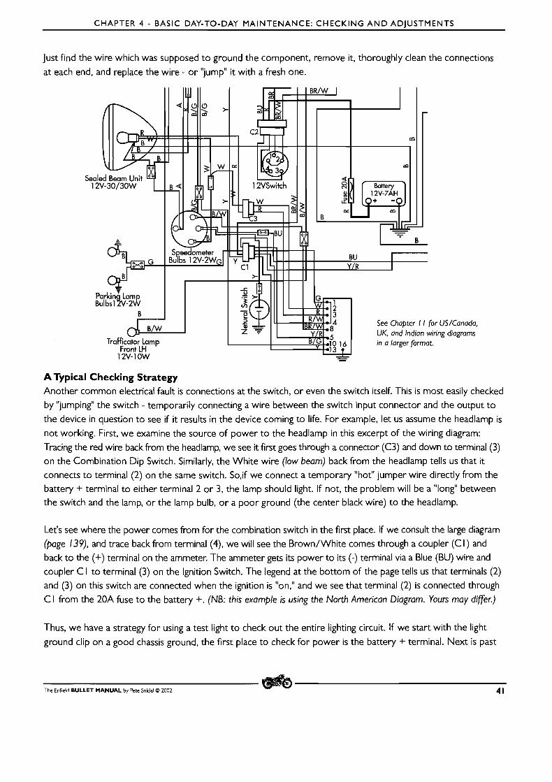
CHAPTER 4 - BASIC DAY-TO-DAY MAINTENANCE: CHECKING A N D ADJUSTMENTS
Just find the wire which was supposed to ground the component, remove it, thoroughly clean the connections
at each end, and replace the wire - or "jump" it with a fresh one.
A Typical Checking Strategy Another common electrical fault is connections at the switch, or even the switch itself. This is most easily checked by "jumping" the switch - temporarily connecting a wire between the switch input connector and the output to the device in question to see if it results in the device coming to life. For example, let us assume the headlamp is
not working. First, we examine the source of power to the headlamp in this excerpt of the wiring diagram: Tracing the red wire back from the headlamp, we see it first goes through a connector (C3) and down to terminal (3) on the Combination Dip Switch. Similarly, the White wire (low beam) back from the headlamp tells us that it connects to terminal (2) on the same switch. So,if we connect a temporary "hot" jumper wire directly from the battery + terminal to either terminal 2 or 3, the lamp should light. If not, the problem will be a "long" between the switch and the lamp, or the lamp bulb, o r a poor ground (the center black wire) to the headlamp.
Let's see where the power comes from for the combination switch in the first place. If we consult the large diagram (page 139), and trace back from terminal (4), we will see the Brown/White comes through a coupler (C I ) and back to the (+) terminal on the ammeter. The ammeter gets its power to its (-) terminal via a Blue (BU) wire and coupler C I to terminal (3) on the Ignition Switch. The legend at the bottom of the page tells us that terminals (2) and (3) on this switch are connected when the ignition is "on," and we see that terminal (2) is connected through C I from the 20A fuse to the battery +. (NB: this example is using the North American Diagram. Yours may difer.)
Thus, we have a strategy for using a test light to check out the entire lighting circuit. If we start with the light
ground clip on a good chassis ground, the f i rs t place to check for power is the battery + terminal. Next is past
The Enfield BULLET MANUAL by Pete Snidal O 2002 4 1
CHAPTER 4 - BASIC DAY-TO-DAY MAINTENANCE: CHECKING A N D ADJUSTMENTS
the fuse to the ignition switch - terminal (4.) If power is shown there, we next check terminal (3) with the ignition
turned on. This should result in power to the both ammeter terminals (the ammeter should pass current at all times) and to any and all connections you can trace from there.
Voltage Drops As a current travels along a circuit, from the battery + through all the components such as wires, switch(es), the
component itself, the ground connections, the chassis itself, and back to the battery, each resistance will result in a voltage drop. The sum of all the voltage drops will be the applied voltage - that of the battery. Ideally, there
should be only one voltage drop - that through the component, such as a light bulb. You may test this by turning on the light, and checking the voltage at the battery terminals, and at the light bulb. If these voltages are identical,
you know there are no other resistances eating some of your battery voltage, such as poor switches, too-thin
wires, bad grounds, etc. You may also check for resistance by looking for a voltage drop across any or all of the
conductors. For example, with the light on, check for any voltage between the battery + terminal and the headlight
high beam terminal, with the high beam on. Use a low voltage scale, such as 0-.5V or 0- 1.5. (with analog needle-type multimeters, always make your first connections tentatively -just touch the second probe momentarily observing that the
needle makes no abrupt swings past either end of the scale.) There should be no voltage reading, since a drop between battery terminal and headlight terminal indicates a resistance. If there is one, a switch, or conductor is at fault. Do this also with the battery - terminal and the ground terminal on the headlight itself. If a voltage drop is
found, you know you have a bad ground. These can best be corrected by directly running a ground wire from battery to headlight ground paralleling the cruder chassis ground.
These are examples of the logic you need to use to figure out problems with your electrical system. See pages 138- 142
for US/Canada, UK and Indian wiring diagrams. You may want to trace the circuit concerned with a coloured felt pen.
VALVE ADJUSTMENT
I. Description:The Valve Train The Valve Train is composed of the cams, the tappets, the valve adjusters, the pushrods, the rocker arms, and the valves themselves. As the running engine rotates its cams, they force the cam followers, or tappets, up, thus forcing the pushrods up, which force the rockers to rotate against the valve springs, opening the intake and exhaust valves
at the proper times, relative to piston position, or they release this force, allowing the springs to close them.
Operating Clearance There must be operating clearances in both halves of the valve train, since if the valves are not allowed to seat fully when closed, escaping hot gas flow will damage the valves and their seats. If the clearance is too great, the
resultant hammering of the loose parts will damage them beyond repair. For these reasons, maintaining proper
valve train adjustment is an important part of looking after your Bullet.
2. Checking Valve Train Clearance Clearances may not require frequent adjustment, but it should be a constant occurrence to check them. If the
valves become loose, the noise will tip off the wary owner, but excessive tightness is much harder to detect -
although in extreme cases, compression will be nonexistent when the machine is cold. Fortunately, they rarely
get tight in operation; looseness is much more common.
42 The Enfield BULLET MANUAL by Pete Snidal O 2002
CHAPTER 4 - BASIC DAY-TO-DAY MAINTENANCE: CHECKING A N D ADJUSTMENTS
Hot or Cold? There are two opposing schools of thought on valve adjustment: engine hot, or engine cold. This is because, as
engine temperature changes, expansion or contraction takes place, and the valve setting will change accordingly.
The obvious advantage of setting the valves cold is that you won't be as likely to suffer burns or discomfort
from dealing with hot engine parts - the valve adjusters are washed in returning oil from the rockers during
engine operation. But the advantage of setting the clearances at a temperature much closer to that when the
engine is in operation would outweigh this minor inconvenience. So it's no surprise that the majority of happy
mechanics seem to check and set valve clearances with the engine at operating temperature.
Checking While Engine is Running Some more experienced Bulleteers check their valve clearances with engine hot and running. Since this is the
condition in which it is most important to have them right, this is to be preferred. Simply run the machine into the
shop, and remove the tappet cover. With engine idling (at tickover), attempt to rotate the tappets as they bounce up and down. They should be turnable, but with a slight resistance. If either turns quite loosely, shut the engine down and tighten, then check again. D O NOT GET YOUR FINGERS CAUGHT BETWEEN THE OSCILLATING
ADJUSTERS A N D THE BOTTOIY OF THE TAPPET CHEST!
Checking With Engine Stopped Checking valve clearances must be done when the tappets/valve lifters are at the back of the cams - at TDC
(top dead center) or close to it, between the compression and power strokes. Finding the spot is easy with the
compression release. With the gearbox in neutral, apply kickstarter until you feel the piston stop on the compression
stroke. Pull the compression release, and ease the piston up to the top of the stroke, listening for the wheeze
of air out of the exhaust pipe through the decompressor. When this wheeze stops, you're ready for checking
your valve clearances.
Checking - Do They Require Adjustment? Remove the tappet cover at the base of the cylinder, on the right side. The pushrod adjusters will be visible. First, check to see that they rotate freely - if not, they're too tight, and this is very bad - the valves won't be seating properly and will burn in short order. Then try to wriggle them up and down. If you can feel any movement, they're too loose. (NB: if attempting to set with engine cold, remember that the exhaust valve train will get hotter than
the intake, and for this reason the exhaust must be set looser at cold. When setting hot, they want both to be the same.)
If they're just right, replace the tappet cover and ride on. If not, adjust:
Adjusting Valve Clearances I t may be helpful to remove the spindle which holds the tappet cover in place. Unscrewing this will give you a lot
more room to work. Slacken off the locknut, using one wrench/spanner of suitable size on the adjusting screw,
and one on the locknut. With the locknut loose (a half-turn will do fine) tighten or loosen the adjusting screw,
checking often until you get the proper "feel" of zero clearance - the rod will spin, but with no up/down feel.
Now, all you have to do is tighten the locknut against the bottom of the pushrod, without changing the adjustment
by any movement of the screw. Do this in stages, first get it snug, then re-check your "feel." If it hasn't changed, you may wish to take a short test ride. Put the cover on, ride around the block, return, pull the cover, and check the pushrods for spin at idle/tickover. If good, shut down and tighten properly; if not, readjust.
The Enfield BULLET MANUAL by Pete Snidal O 2002 43

CHAPTER 4 - BASIC DAY-TO-DAY MAINTENANCE: CHECKING A N D ADJUSTMENTS
It's very important to have your valves set properly, so check them often, and keep an ear open to them loosening
up. (The valve train on these units is pretty noisy, so you have to develop an ear for that "little extra" that tells you to
postpone your trip and have a look. Better safe than sorry!)
Inconsistency Although not completely routine, it is a common enough occurrence to find that your valve clearances just
won't "stay put." There are a number of reasons why this can happen, the two most common and easily fixable
concern pushrod anomalies:
m Pushrods have been known to bend in use. A bent pushrod will of course give very inconsistent clearance
readings - as it rotates, it's effective length will change. When rotating the pushrod to see that the clearance
is correct, look carefully for any signs of eccentricity in the rotating pushrod. If you see any, the pushrod
will have to be replaced.
m Another difficulty sometimes experienced is that of one or another of the pressed-on ends of a pushrod
coming loose. This will also result in serious inconsistency of valve adjustment, and once again mandates the replacement of the offending pushrod.
If you have difficulty maintaining valve adjustment and removing the pushrods has shown no problems, you will have to go further and check the valves and guides. This is covered in the heavy mechanicals section of this manual.
Hot vs Cold - a Reprise
Many owners report that, having set their valves hot, so that the pushrods will just spin, the next morning the
engine has no compression due to the adjustment having tightened up when cooled. In this case, you have to reach
a compromise, in which they aren't too tight to start in the morning, yet not so loose that clearance is excessive
when the engine reaches operating temperature. Although tightness is bad at operating temperatures, a little
too-tight a setting during warm-up is permissible - just so long as it's slack enough to give you the compression necessary for starting.
44 The Enfield BULLET MANUAL by Pete Snidal C3 2002
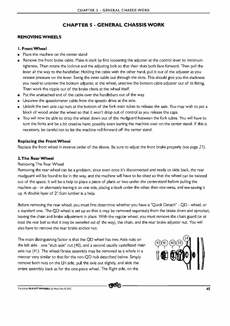
CHAPTER 5 - GENERAL CHASSIS WORK
CHAPTER 5 - GENERAL CHASSIS WORK
REMOVING WHEELS
I. Front Wheel Place the machine on the center stand
m Remove the front brake cable. Make it slack by first loosening the adjuster at the control lever to minimum
tightness. Then rotate the locknut and the adjusting bolt so that their slots both face forward. Then pull the
lever all the way to the handlebar. Holding the cable with the other hand, pull it out of the adjuster as you release pressure on the lever. Swing the inner cable out through the slots. This should give you the slackness you need to unscrew the bottom adjuster, at the wheel, unscrew the bottom cable adjuster out of i ts fitting.
Then work the nipple out of the brake clevis at the wheel itself.
m Put the unattached end of the cable over the handlebars out of the way.
m Unscrew the speedometer cable from the speedo drive at the axle.
m Unbolt the two axle cap nuts at the bottom of the fork main tubes to release the axle. You may wish to put a
block of wood under the wheel so that it won't drop out of control as you release the caps.
m You will now be able to drop the wheel down out of the mudguard between the fork tubes. You will have to
turn the forks and be a bit creative here; possibly even leaning the machine over on the center stand. If this is
necessary, be careful not to let the machine roll forward off the center stand.
Replacing the Front Wheel Replace the front wheel in reverse order of the above. Be sure to adjust the front brake properly (see page 27).
2.The Rear Wheel Removing The Rear Wheel
Removing the rear wheel can be a problem, since even once it's disconnected and ready to slide back, the rear
mudguard will be found to be in the way, and the machine will have to be tilted so that the wheel can be twisted
out of the space. It will be a help to place a piece of plank or two under the centerstand before pulling the
machine up - or alternately leaning it on one side, placing a block under the other, then vice-versa, and see-sawing it
up. A double layer of 2"-5cm lumber is a help.
Before removing the rear wheel, you must first determine whether you have a "Quick Detach" - Q D - wheel, or
a standard one. The QD wheel is set up so that it may be removed separately from the brake drum and sprocket,
leaving the chain and brake adjustment in place. With the regular wheel, you must remove the chain guard (or at least the rear bolt so that it may be swivelled out of the way), the chain, and the rear brake adjuster nut. You will
also have to remove the rear brake anchor nut.
The main distinguishing factor is that the QD wheel has two Axle nuts on
the left side - one "stub axle" nut (40), and a second usually castellated main
axle nut (4 1). The wheel/brake assembly may be removed as a whole in a
manner very similar to that for the non-QD hub described below. Simply
remove both nuts on the LH side, pull the axle out slightly, and slide the
entire assembly back as for the one-piece wheel. The Right side, on the \ I
The Enfield BULLET MANUAL by Pete Snidal O ZOO2 4 5
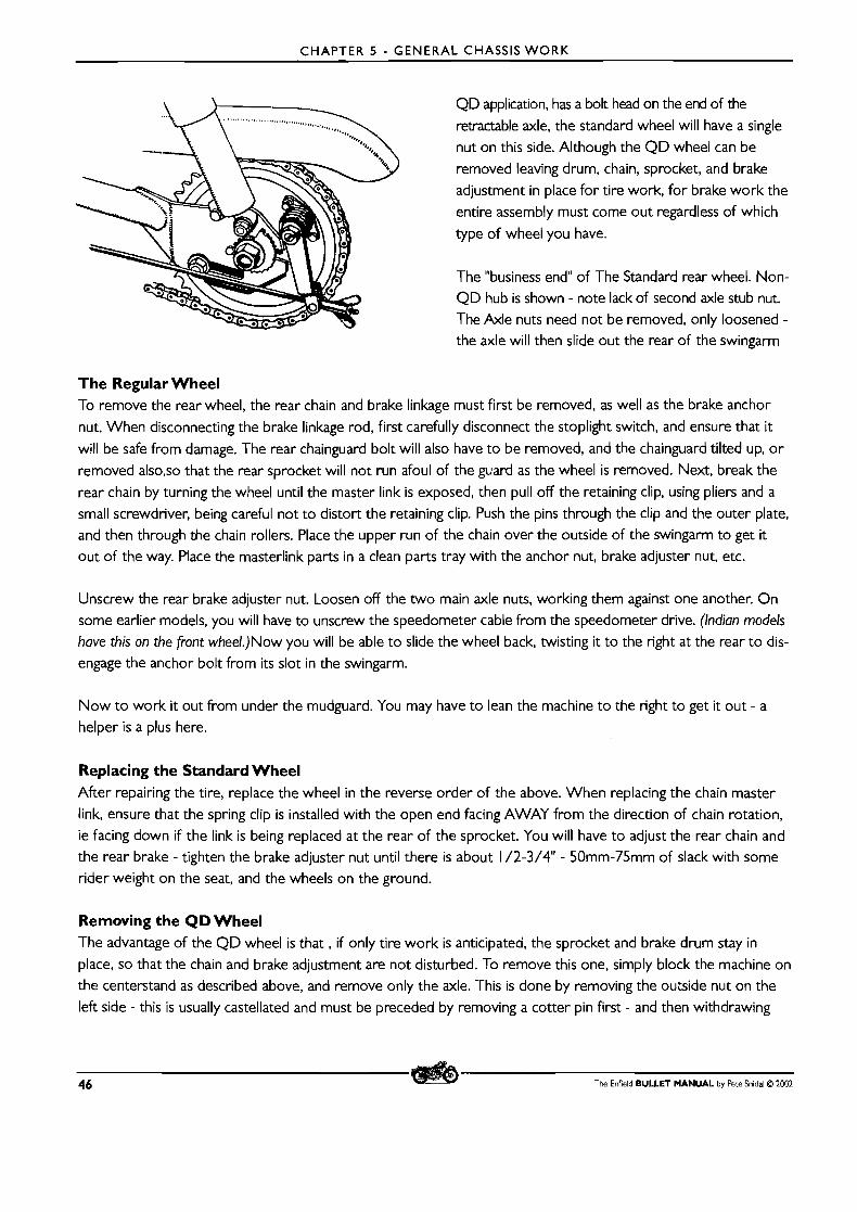
CHAPTER 5 - GENERAL CHASSIS WORK
QD application, has a bolt head on the end of the
retractable axle, the standard wheel will have a single
nut on this side. Although the QD wheel can be
removed leaving drum, chain, sprocket, and brake
adjustment in place for tire work, for brake work the
entire assembly must come out regardless of which
type of wheel you have.
The "business end" of The Standard rear wheel. Non-
QD hub is shown - note lack of second axle stub nut. The Axle nuts need not be removed, only loosened - the axle will then slide out the rear of the swingarm
The Regular Wheel To remove the rear wheel, the rear chain and brake linkage must first be removed, as well as the brake anchor
nut. When disconnecting the brake linkage rod, first carefully disconnect the stoplight switch, and ensure that it
will be safe from damage. The rear chainguard bolt will also have to be removed, and the chainguard tilted up, o r
removed also,so that the rear sprocket will not run afoul of the guard as the wheel is removed. Next, break the
rear chain by turning the wheel until the master link is exposed, then pull off the retaining clip, using pliers and a
small screwdriver, being careful not to distort the retaining clip. Push the pins through the clip and the outer plate,
and then through the chain rollers. Place the upper run of the chain over the outside of the swingarm to get it
out of the way. Place the masterlink parts in a clean parts tray with the anchor nut, brake adjuster nut, etc.
Unscrew the rear brake adjuster nut. Loosen off the two main axle nuts, working them against one another. On
some earlier models, you will have to unscrew the speedometer cable from the speedometer drive. (Indian models
have this on the front wheel.)Now you will be able to slide the wheel back, twisting it to the right at the rear to dis-
engage the anchor bolt from its slot in the swingarm.
Now to work it out from under the mudguard. You may have to lean the machine to the right to get it out - a
helper is a plus here.
Replacing the Standard Wheel After repairing the tire, replace the wheel in the reverse order of the above. When replacing the chain master
link, ensure that the spring clip is installed with the open end facing AWAY from the direction of chain rotation,
ie facing down if the link is being replaced at the rear of the sprocket. You will have to adjust the rear chain and
the rear brake - tighten the brake adjuster nut until there is about 1 /2-3/4" - 50mm-75mm of slack with some rider weight on the seat, and the wheels on the ground.
Removing the QD Wheel The advantage of the QD wheel is that, if only tire work is anticipated, the sprocket and brake drum stay in
place, so that the chain and brake adjustment are not disturbed. To remove this one, simply block the machine on the centerstand as described above, and remove only the axle. This is done by removing the outside nut on the
left side - this is usually castellated and must be preceded by removing a cotter pin first - and then withdrawing
46 The Enfield B U L L E T M A N U A L by Pete Snidal O 2002

CHAPTER 5 - GENERAL CHASSIS WORK
the axle and wheel adjuster cam out the right side. Support the wheel as you do this, so that the axle will come out smoothly. Then, remove the spacer between the wheel and the right-side swingarm, and pull the wheel away
from the brakedrum/sprocket assembly, which is left undisturbed.
The Cush Drive Rubbers The cush drive rubbers lie inside the interface between hub and wheel. There are bosses and sockets cut into the parts to keep them in place for reassembly.
On higher-mileage units, you may want to check for looseness in the cush drive before removing the wheel, so that you can replace the rubbers on reassembly.
Checking the Cush Drive Rubbers Before removing the wheel, even before putting the machine on the center stand, apply the rear brake, and rock the machine fore and aft, observing how much movement is possible against the cush drive unit in the hub. If the wheel rim can move much more than about I 1 /2" - 40mm along i ts circumference, you may want to order a set of cush drive rubbers, so that you can change them the next time you have the wheel apart.
Replacing the QD Rear Wheel This is done in reverse order from the above. Be sure to replace the cotter pin through the castellated axle nut, and to check the chain and rear brake adjustment while you have your tools handy.
CHANGING TIRES
Changing motorcycle tires can be difficult. The sum of my experience over many years of motorcycling has taught me these things:
m I'd rather get someone else to do it - it's much easier for those who've done i t already today - o r this week.
It's a definite knack. m A good set of motorcycle tire irons is a MUST m Tire beads - the inner rim of the tire - are made of many turns of wire surrounded by rubber - they WILL
NOT stretch! They must be finessed over the rim after all possible slack has been negotiated by dropping all the other parts of the tire into the drop center, completely unimpeded by any bits of the inner tube, security bolts, etc. getting in the way
m Soapy water is a great help m It gets easier as you do it more. The best experiences I've had with tire changes have always been the fourth
one in the day
The Enfield BULLET MANUAL by Pete Snidal O 2002 47
CHAPTER 5 - GENERAL CHASSIS WORK
With these principles in mind, here are the steps:
m With the machine on the center stand, remove the wheel (see page 45). m An open oil drum is a great tire stand - if it's full of trash (and why else would it be in the shop?) put a piece of
plastic sheet over the trash to catch valves, security bolt nuts, tire irons, etc. before proceeding. m Deflate the tire by unscrewing the valve core. Put the removed core in a safe place - beside the tire inflator
chuck is a good one. Remove the valve core nut, if fitted, and put it away as well. See the note on this nut below during reinstallation.
m If security bolt(s) is/are fitted, completely unscrew the nuts. Put them with the valve core.
a Place the wheel on two or three blocks of wood - under the tire circumference - on the floor. Stand/jump/hammer on the tire walls until the top bead parts from the rim around the entire circumference. Flip the wheel over and repeat.
m With wheel back on "bench," (the oil drum) soap the top bead of the tire liberally. Push any security bolts all the way into the tire.
m Press the entire circumference of the tire as deeply as you can into the "dropped center" of the rim. Ensure
that the tube does not get in between the tire and the rim at any point. You are working for maximum slackness
of the bead everywhere except at the point of withdrawal - at the valve stem. m A t the valve stem, carefully pry the upper bead of the tire over the top rim. Be absolutely sure the tire is
tight against the dropped center everywhere else on the rim, and that it is unimpeded by tube or security
bolts at any point. Be very careful at all stages not to pinch the tube between the tire iron and the tire or rim. m Holding the first part you've pulled over with one tire iron, continue around the rim with another. This
should go easily. If not, see the previous step. Some tires are nastier than others. Heavy duty Motocross Knobbies are the worst, radial street tires the best. Be VERY careful not to pinch the tube between tire iron and inner bead.
m Once you've got the top bead off, remove the security bolt(s), if any.
Remove the tube. m If repairing a flat, test the tube by reinflating and checking under water, o r by brushing soapy water onto it.
Repair any leak with a flat repair kit. Identify the corresponding spot on the tire where the leak was found in the tube, and remove any object which may have embedded itself in the tire. If the hole is significant, patch this hole on the inside of the tire. Reverse the tube on reinstallation so that the patches won't be accumulated in one spot.
W If replacing the tire, pry the other bead off the same side of the wheel. Use soapy water on the bead, and be
sure to keep all the bead except the part you're prying out well into the center of the rim.
Replacing the Tire m Replacing the tire and tube is pretty well the reverse of the above procedure. Lower bead, tube, security
bolts, upper bead. Use lots of soapy water on the beads, be sure the security bolts are well down in the tire before prying the bead over the rim (but put a nut on the end of the bolt so you won't lose it in there). Put a
nut on the valve stem also, but don't bottom it - just start it, so that the valve stem won't get lost. As you pry the tire over the top rim, be careful that the tire doesn't turn about the rim - the valve stem will cock
over if this happens. Be very careful not t o pinch the tube between the inside of the bead and the tire iron.
m If security bolt(s) is/are present, be careful t o ensure that the tube doesn't get in between the bolt foot and the rim, or the bead of the tire.
48 The Enfield BULLET MANUAL by Pete Snidal O 2002

CHAPTER 5 - GENERAL CHASSIS WORK
m Once the tire is back over the entire rim, press the security bolts in and out to ensure that they move freely
all the way - this is your indication that the tube is not caught between the foot and rim or bead. Apply more soapy water to the tire beads. Temporarily inflate the tube with the valve core still not in place.
Use low pressure. Use the valve cap to hold the air.
Carefully inspect the bead line on the walls of the tire. Ensure that the bead line is concentric to the rim on
both sides. If not, bounce the wheel on the floor, spinning it if necessary. A hammer may need to be applied
radially to the tire wall to line the bead line up properly for the full circumference on both sides. m Once the bead line is concentric with the rim, you may remove the valve cap, replace the valve core, and
inflate the tire to proper pressure. 28 psi for normal use. m Replace the wheel on the machine. m Valve Stem Nut: do not tighten the valve stem nut right down to the rim. It is not rare for the tube to "creep"
around the rim, inside the tire. This condition will be signalled in one of two ways: either the valve stem will
be canted as it leaves the hole in the rim, (no nut in place) or it will be broken off and the tire will be flat (nut
tightened down to rim.) The nut should be discarded, o r left loose halfway up the stem - it is a handy item in
tube reinstallation. Tube creep is most common in cases of underinflation, and security bolt(s) are one way to correct this.
REPLACING CONTROL CABLES
Inspection You should inspect the condition of your control cables on a regular and ongoing basis. Imagine trying to ride
home if your throttle or clutch cable broke! Things to look out for are:
m Frayed or broken strands on inner cable, at or just behind the nipple in the control lever
m Failure of the nipple to turn freely in the control lever when operated - lubrication is necessary at all times
m Broken, burnt, or abraded outer sheath - this will admit water and dust, leading to eventual failure of the inner
m "Scratchy" or "grinchy" operation - particularly the throttle will feel this way if the inner cable is frayed inside
the outer shell
If in doubt, replace the cable. You don't have to waste a half-good used cable; you can put it in the toolbox o r
tape it somewhere on the machine for a spare. (Many Enduro riders tape a second cable alongside their throttle and
clutch cables, so they may changed in a hurry on the trailside. Be sure the ends are protected from weather.)
Replacement This is a straightforward operation involving disconnecting the cable at each end, routing a fresh cable alongside
it, and removing o r taping up the old cable. In order of likelihood:
Throttle Cable I. RELEASE THE THROTTLE CABLE AT THE CARBURETOR
m Remove Fuel Tank - turn off fuel tap, undo fixing bolts, remove tank - depending on seat fitted, it may be
necessary first to remove the seat
The Enfield BULLET MANUAL by Pete Snidal O 2002 49
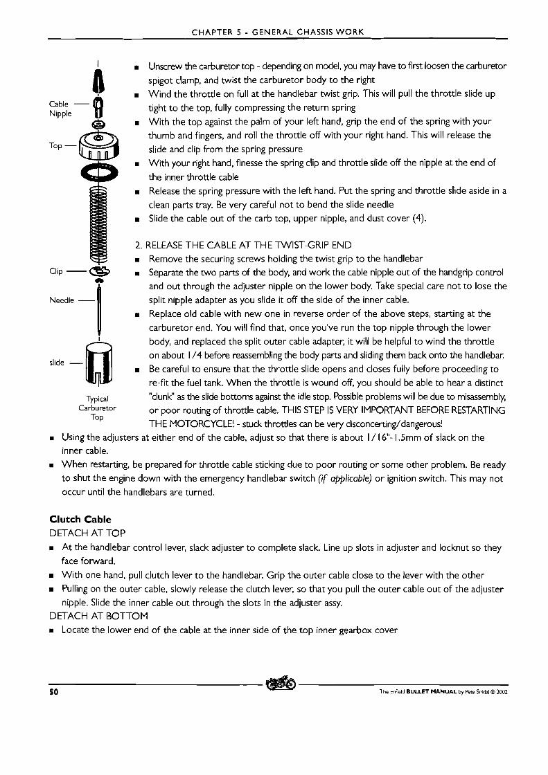
CHAPTER 5 - GENERAL CHASSIS WORK
A m Unscrew the carburetor top - depending on model, you may have to first loosen the carburetor
spigot clamp, and t w i s t the carburetor body t o the right
8 m Wind the throttle on full at the handlebar tw i s t grip. This will pull the throttle slide up
Cable - tight t o the top, fully compressing the return spring Nipple
m With the top against the palm of your left hand, grip the end of the spring with your
Top - & thumb and fingers, and roll the throttle off with your right hand. This will release the
slide and clip from the spring pressure m With your right hand, finesse the spring clip and throttle slide off the nipple at the end of
the inner throttle cable
m Release the spring pressure with the left hand. Put the spring and throttle slide aside in a
clean parts tray. Be very careful not t o bend the slide needle m Slide the cable out of the carb top, upper nipple, and dust cover (4).
2. RELEASE THE CABLE AT THE TWIST-GRIP END m Remove the securing screws holding the twist grip t o the handlebar
Clip -a Separate the two parts of the body, and work the cable nipple out of the handgrip control
I and out through the adjuster nipple on the lower body. Take special care not to lose the Needle - split nipple adapter as you slide it off the side of the inner cable.
m Replace old cable with new one in reverse order of the above steps, starting at the
carburetor end. You will find that, once you've run the top nipple through the lower
6 body, and replaced the split outer cable adapter, it will be helpful t o wind the throttle
on about 1 /4 before reassembling the body parts and sliding them back onto the handlebar. slide -
m Be careful to ensure that the throttle slide opens and closes fully before proceeding to
re-fit the fuel tank. When the throttle is wound off, you should be able to hear a distinct
Typical "clunk" as the slide bottoms against the idle stop. Possible problems will be due to misassembly, Carburetor or poor routing of throttle cable. THIS STEP IS VERY IMPORTANT BEFORE RESTARTING
TOP THE MOTORCYCLE! - stuck throttles can be very disconcerting/dangerous!
m Using the adjusters at either end of the cable, adjust so that there is about I / 1 6"- 1.5mm of slack on the inner cable.
m When restarting, be prepared for throttle cable sticking due to poor routing or some other problem. Be ready to shut the engine down with the emergency handlebar switch (if applicable) or ignition switch. This may not occur until the handlebars are turned.
Clutch Cable DETACH AT TOP
m A t the handlebar control lever, slack adjuster to complete slack. Line up slots in adjuster and locknut so they face forward.
m With one hand, pull clutch lever t o the handlebar. Grip the outer cable close to the lever with the other
m Pulling on the outer cable, slowly release the clutch lever, so that you pull the outer cable out of the adjuster
nipple. Slide the inner cable out through the slots in the adjuster assy. DETACH AT BOTTOM
Locate the lower end of the cable at the inner side of the top inner gearbox cover
50 The Enfield BULLET MANUAL by Pete Snidal O 2002
CHAPTER 5 - GENERAL CHASSIS WORK
m Remove the upper gearbox cover access plate. This will expose the lower cable nipple where it fits through
the upper bellcrank lever m pull on the outer cable until the inner shows m Grasp the inner cable and push it through the bellcrank lever until the nipple is clear
m Work the nipple around the end of the lever, and the inner cable out through the slot in the end of the liver
m Withdraw the cable.
m Refit the new cable in reverse order. Adjust to about 1 /8" - 3mm slack in cable. Set adjusters so that upper adjuster
has about 1 /4" - 6mm of slack, to allow some room for cable and linkage adjustment if necessary at a later time.
m This is a good time to adjust the clutch linkage (See page 23)
Front Brake m Slack off the handlebar control cable adjuster, and line up the slots in the star adjuster and inner cable nipple
m Pull the brake lever against the handlebar, and then, using your other hand, pull the outer cable away from the
lever assy. as you release tension on the outer cable. m Slip the inner cable through the slots in the star adjuster and cable nipple. m Unscrew the cable nipple at the wheel hub end m Twist the inner cable end nipple out of the brake actuator arm m Replace the cable in reverse order of above m Be sure to adjust your front brake properly before restarting the machine. Tighten the adjuster(s) until the brake
contacts the drum within the first 1 /2"- 12mm of control lever movement (at the outer end of the lever)
REPLACING BRAKE SHOES
Removing wheels has already been dealt with earlier in this Chapter (See page 45). Obviously, to replace brake
shoes, the wheel in question must first be removed.
Brake shoes are supplied from the dealers lined - re-lining is not common. So all that is necessary is to remove
the old shoes, clean up the parts, and replace them. Then it is advisable to check the "arcing" - to make certain
that the shoes contact the drum over as much of the area as possible when the brakes are applied.
The Rear Brake Shoes Removal of the standard hub has been dealt with as above. In the case of the QD hub, the hub/sprocket assembly will have to be removed from the left side swingarm once the QD wheel has been removed. This will mean removing
the chain guard, disconnecting the chain, and slacking off the stub axle nut, as well as removing the brake anchor
stud nut. Be sure to disconnect the stop light switch from the actuator rod, to prevent damage to this fragile
switch. Once the fittings have been loosened/removed, the hub/sprocket unit may be slid back through the slot
in the swingarm - twist i t to the left to disengage the brake anchor stud from its slot in the swingarm.
Once the wheel is on the bench, remove the cover plate nut, and separate the cover plate from the drum/sprocket
assembly. (Note the position of the lever relative to the cover plate) - the anchor stud is a convenient reference.
Then, the shoes may be removed in one of two ways:
The Enfield BULLET MANUAL by Pete Snidal O ZOO2 5 1
CHAPTER 5 - GENERAL CHASSIS WORK
The Whole-Hog Method Unscrew the brake shoe pivot pin lock nut and the operating lever nut. Remove the lever.
m Remove brake shoes, return springs, pivot pin and operating cam as an assembly from the cover plate by
unscrewing the pivot pin and applying light blows with a hammer and drift on the end of the operating cam shaft.
m The return spring can then be unhooked from the brake shoes
The Simple~But-Trickier Method Alternately, the pivot pin and actuator lever and shaft may be left in place on the mounting plate.
m In this case, the brake shoes, with the return springs, may be worked around the ends of the pivot pin and
actuator cam with screwdrivers used as prybars and wedges, - it is a help t o tilt the shoes upward at their
centers at the proper moment - and the springs then removed. Watch your fingers! m The shoe assembly (shoes and springs) may then be separated and the old shoes put aside.
A Note on Removing the Brake Actuator Shaft Lever To free the lever from the shaft, loosen the nut, and using a soft (brass or aluminum) drift, support the lever and give the end of the shaft a sharp tap with a suitable loosening device. (Don't use force; just a bigger hammer!) The nut has been left on to minimize thread distortion. Be careful not t o use enough force to distort the threads - taking the nut the rest of the way off will help to reform them if slightly distorted. If excessively distorted, the
nut won't come off. The cover plate and related parts may then be cleaned up for re-assembly.
Re-assembly of Brake Shoes Regardless of method used for disassembly, the actuator shaft should be removed for cleaning and lubrication. Reassembly will then be some combination of the procedure below.
If the Total Removal method was used, re-assemble the shoes, springs, actuator cam/shaft, and pivot pin as a unit. Be sure to lubricate the actuator shaft by applying high-temperature grease sparingly. Assemble the unit to the cover
plate. If the shorter method was used, it is often possible t o assemble the shoes, with the springs, and then tilt the outsides upward, engage the insides over their pins, and then spring the outsides down. Watch your fingers and hands - those springs can PINCH!
Ensure tightness of the brake shoe pivot pin in the cover plate. If the actuator lever has been removed, replace it and
put on the the holding nut finger-tight to hold things together. The parts may then be cleaned and lubricated. Grease as mentioned above - sparingly - on the actuator shaft and cam faces, as well as on the pivot pin. NB: grease on brake linings = grief.
Centering the Operating Cam Bush 'The bolt holes in the cover plate for locating the rear brake cam bush are slotted, to enable the brake shoe assembly to
be centered in the drum. Before fitting the brake cover plate back into the drum, loosen the locknuts and the cam bush
retainer mounting bolts. Then, fit the cover plate assembly with the new shoes over the spindle into the brake drum and apply the brake as hard as possible by means of applying toque to the operating lever - a large adjustable wrench
on the end of the lever will be helpful. This will center the shoes in the drum. Then tighten the mounting bolts as much as possible, remove the cover plate assy., and complete tightening and replace the locknuts. Now check the arc.
52 The Enfield B U L L E T M A N U A L by Pete Snidal @ 2002
CHAPTER 5 - GENERAL CHASSIS WORK
Checking the Arc Now, to check the arcing - to ensure that the shoes contact the drum for their full circumference (and width) . This is extremely important to proper brake operation. O f course, if the brakes are just assembled as is, and
used long enough (and sparingly enough) - the high spots will eventually wear down, but in actual practice, the
high spots can "glaze" and harden, preventing proper seating. For this reason, it is much to be preferred to verify
that the shoes are properly arced before resuming operation.
This is done by using marker on the shoe faces, such as chalk. Scribe lines of chalk lightly across the shoes for their
full circumference, and then reassemble the brake. Then, turn the cover plate inside the drum, applying enough brake pressure with a spanner on the actuator nut. The object is to smear the chalk at the places of contact.
IVow, remove the cover plate again and examine the shoes. The high spots (smeared places) must be sanded down to
the level of the low spots. There are a number of ways to do this, usually involving sandpaper. (In extreme cases, belt
sanden, disk sanden, body files, etc. have been known to be put into play.) Use 80 or 100 grit to start. It may be applied to
the shoe using a sanding block, to rough things in. The best way is to "line" the drum with a strip of sandpaper, folded
over the open edge of the drum to hold it in place. Re-fit the cover plate, and rotate it within the drum, applying brake
as much as you can while still moving the plate. Do this until the entire surface of each shoe is scuffed.
This can be a long and monotonous procedure, but it is very worthwhile - the longer the procedure, the more
necessary it was.
Once the shoes have been properly arced, assemble in reverse order. Be especially careful of the safety considerations - chain adjustment, brake adjustment, tightening of all bolts, adjustment of stop light switch, etc.
Front Wheel First, remove the wheel.Put the wheel on the bench and unscrew the cover plate nut. (For TLS brake, loosen the lock nuts
on the link rod and turn link rod so that both brake shoes become free and are not in contact with the brake drvm). Pull cover
plate assembly out of brake drum. Remove brake shoes and springs as described for rear wheel above.
First making a note of the position of each actuator arm relative to its shaft, remove the actuator arm, and then
i ts shaft. This is best done one at a time, so that you can be sure of proper reassembly, Clean all parts before
lubricating. To free the arms from the shafts, loosen the nut, and using a soft (brass or aluminum) drift, support
the lever and give the end of the shaft a sharp tap with a suitable loosening device. (Don't use force; just a bigger
hammer!) The nut has been left on to minimize thread distortion. Be careful not to use enough force to distort the threads - taking the nut the rest of the way off will help to reform them if slightly distorted. If excessively distorted,
the nut won't come off. Clean and lubricate the actuator shaft, and reassemble before doing the second one.
When all parts have been cleaned and lubricated, fit the fresh brake shoes to the operating cams and pins, - for
this first stage, the return springs may be omitted. Then check the arc, as above, re-arcing as necessary. Finally,
fit the return springs and do the fine arcing. Arcing is especially important with the front brake, as this supplies a full 75% of your braking ability.
Re-fit the wheel to the machine in reverse order of removal. You may wish to refer to page 45 again.
The Enfield BULLET MANUAL by Pete Snidal O 2002 53
CHAPTER 5 - GENERAL CHASSIS WORK
Added Brake Refinements The mechanical advantage of the application lever to the brake cam may also be improved - at a cost of having
t o pay greater attention to adjustments. The simplest way is to modify the angle of the brake actuator arm to
the linkage rod, in the case of the rear brake, or t o the cable, in the case of the front. If the actuator arm is at
right angles to the cable or rod at the point of brakeshoe contact, the mechanical advantage will be greatest.
The length of the actuator arm may also be increased. If this route is chosen, remember that in modifying brake parts, extreme care must be taken that the modifications are as strong as, or stronger than, the original - you don't
want your brake arm breaking off at the critical time when you're braking extra-hard. This route is for the expert
metalworker - if in doubt, get a professional on the job. Generally, addition of an inch is about maximum - and remember that the price of extra braking power is at the expense of greater lever movement, and necessity for
more frequent adjustment.
THE WHEEL BEARINGS
Lubrication The factory recommends that Front and rear wheel bearings should be lubricated by packing them with grease at 10,000 Km-6,000mi intervals. To do this, the wheels must be removed and the hubs dismantled.
However, wheel bearings are inexpensive - so inexpensive that it is questionable whether or not this maintenance is cost-effective. They may be checked for wear simply by attempting to move the wheels sideways at the rims.
If more than 1 /8"-3mm of play is apparent, then they should be replaced. They should also be replaced or repacked at each brake service - which is of course determined by brake wear. Personally, I use this method to decide on
wheel bearing service, and it's served me well. In particularly dusty/wet conditions, the bearings will wear faster,
but then so will the brakes, and besides, I always replace any wheelbearings with double-sealed prepacked units.
Re and Re Wheel Bearings As with all disassembly, be sure to take careful note of the order in which parts come out or off, and the direction
in which they point. A pencil and some paper may prove valuable.
To remove the bearings, once the wheel is on the bench, remove the cover plate nut and brake cover plate. Put
the nut in a clean parts tray with the other fittings you've removed in taking out the wheel.
I. The Rear Wheel Removal of bearings from center hub assy.
Regular Hub: Drive the axle through the hub from the brake side. Then, using a small drift ( 1 /4"-S/ 16" - 7- 1 Omm)
inserted down the center of the internal bearing spacer, drive out one outer bearing. If you feel around, you'll
find a pair of opposite recesses in the bearing support lip in the hub, at the other end of the bearing spacer,
which will allow you to bring force to bear on the outer race of the bearing. Use these opposite recesses t o
drive the outer race or opposite bearing from i ts pocket in the hub - you'll have t o move the distance piece
(spacer) around t o gain access t o the recesses. The seal will come first, then the bearing.
NB: you may have "sealed bearings" - seal and bearing are one unit. They can be single (one side) o r double (both
54 The Enfield BULLET MANUAL by Pete Snidal O 2002
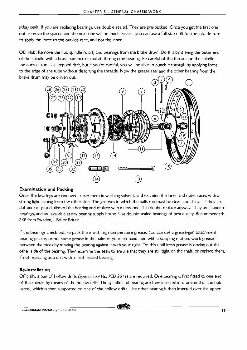
CHAPTER 5 - GENERAL CHASSIS WORK
sides) seals. If you are replacing bearings, use double sealed. They are pre-packed. Once you get the first one
out, remove the spacer, and the next one will be much easier - you can use a full-size drift for the job. Be sure
t o apply the force t o the outside race, and not the inner.
QD Hub: Remove the hub spindle (short) and bearings from the brake drum. Do this by driving the outer end of the spindle with a brass hammer or mallet, through the bearing. Be careful of the threads on the spindle -
the correct tool is a stepped drift, but if you're careful, you will be able to punch i t through by applying force
t o the edge of the tube without distorting the threads. Now the grease seal and the other bearing from the brake drum
Examination and Packing Once the bearings are removed, clean them in washing solvent, and examine the inner and outer races with a strong light shining from the other side. The grooves in which the balls run must be clean and shiny - if they are dull and/or pitted, discard the bearing and replace with a new one. If in doubt, replace anyway. They are standard bearings, and are available at any bearing supply house. Use double-sealed bearings of best quality. Recommended: SKF from Sweden. USA or Britain.
If the bearings check out, re-pack them with high temperature grease. You can use a grease-gun attachment
bearing-packer, o r put some grease in the palm of your left hand, and with a scraping motion, work grease between the races by moving the bearing against it with your right. Do this until fresh grease is oozing out the
other side of the bearing. Then examine the seals t o ensure that they are still tight on the shaft, or replace them,
if not replacing as a unit with a fresh sealed bearing.
Re-installation
Officially, a pair of hollow drifts (Special Tool No. PED 201 1) are required. One bearing is first fitted to one end
of the spindle by means of the hollow drift. The spindle and bearing are then inserted into one end of the hub barrel, which is then supported on one of the hollow drifts. The other bearing is then inserted over the upper
The Enfield BULLET MANUAL by Pete Snidal O 1001 55
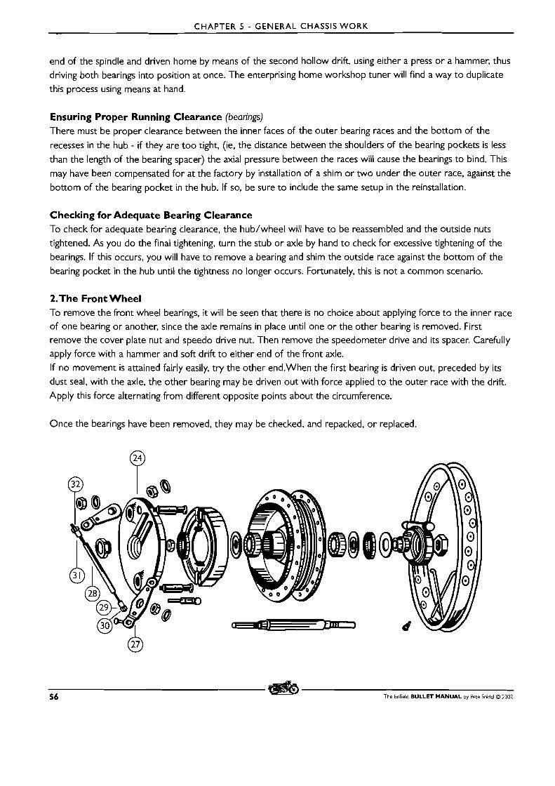
CHAPTER 5 - GENERAL CHASSIS WORK
end of the spindle and driven home by means of the second hollow drift, using either a press or a hammer, thus driving both bearings into position at once. The enterprising home workshop tuner will find a way t o duplicate this process using means at hand.
Ensuring Proper Running Clearance (bearings) There must be proper clearance between the inner faces of the outer bearing races and the bottom of the
recesses in the hub - if they are too tight, (ie, the distance between the shoulders of the bearing pockets is less
than the length of the bearing spacer) the axial pressure between the races will cause the bearings to bind. This
may have been compensated for at the factory by installation of a shim or two under the outer race, against the
bottom of the bearing pocket in the hub. If so, be sure to include the same setup in the reinstallation.
Checking for Adequate Bearing Clearance To check for adequate bearing clearance, the hub/wheel will have to be reassembled and the outside nuts tightened. As you do the final tightening, turn the stub or axle by hand t o check for excessive tightening of the
bearings. If this occurs, you will have t o remove a bearing and shim the outside race against the bottom of the bearing pocket in the hub until the tightness no longer occurs. Fortunately, this is not a common scenario.
2.The Front Wheel To remove the front wheel bearings, it will be seen that there is no choice about applying force to the inner race of one bearing or another, since the axle remains in place until one or the other bearing is removed. First remove the cover plate nut and speedo drive nut. Then remove the speedometer drive and i ts spacer. Carefully apply force with a hammer and soft drift t o either end of the front axle. If no movement is attained fairly easily, try the other end.When the first bearing is driven out, preceded by its dust seal, with the axle, the other bearing may be driven out with force applied t o the outer race with the drift.
Apply this force alternating from different opposite points about the circumference.
Once the bearings have been removed, they may be checked, and repacked, or replaced.
56 The Enfield BULLET MANUAL by Pete Snidal O 2002
CHAPTER 5 - GENERAL CHASSIS WORK
CheckinglPacking Wheel Bearings With the QD hub, there is a third bearing, shown as part ( 1 7) in the drawing. This is a 6005, and will be found to be
a bit more expensive. It is the bearing which takes the full thrust of the pull of the drive chain, and should be checked
carefully. As mentioned above, the wheel bearings are so inexpensive as to render their servicing questionable. Still,
they may be cleaned up in washing solvent, blown out with air, and the inner and outer race ball surfaces checked
with a glass and a strong light from the other side. If there is no sign of pitting or galling, and the surfaces are smooth
and shiny, the bearing may be packed with high-temperature grease and re-used. Replacement bearings are standard -
17 X 40 X 12mm - 6203 for unsealed, 620322 for sealed, available in bearing supply houses worldwide. Watch for
country of origin; Swedish, German, Japanese, or American are still the best.
BROKEN STUD REMOVAL
Removing Screws With Heads Intact If screws, such as case cover screws, still have their heads, but they are so mangled by bad tools that they can no
longer be unscrewed with a screwdriver, first try an impact driver. These can be had at specialty tool shops, and
most motorcycle shops, and their use is self-explanatory. If an impact driver won't work, a drill must be used.
Removing Broken Studs and Screws Even with extreme care, any mechanic will occasionally encounter a broken or stripped stud or screw. When
this happens, one of a number of strategies may be employed. There are three reasons why a stud or bolt will break on being over-torqued:
M Stretching past the breaking point by sheer over-tightening - the stud itself breaks somewhere along its length.
W Corrosion - the stud has become a part of the casting o r nut into which it has been fitted, and
tightening/loosening attempts have caused i t to break off either by twisting o r stretching. W Bottoming - the stud is tightened to the point at which it can go no further into a blind hole, and once again
breaks off due to being excessively twisted.
Penetrating Oil In any of these cases, and even much before the screw/stud has been broken off, penetrating oil should be
used. Use lots, and after i t has had a bit of time to soak in, deliver a sharp rap to the screw with hammer and
small drift. Each of these kinds of breakage has i ts own solution:
W Vice-Grips- In the simplest cases, the broken stud will have enough of i ts length showing to be clamped onto
with vice-grip pliers, and be loose enough in the threads to come out without further problem. In cases of screws holding on such things as case covers, the protruding stud will not show until the rest of them have
been removed - by unscrewing, or in extreme cases drilling off the heads.
W Screw Extractors: In cases in which the threads are loose, but the bolt/stud/screw has broken off below the
top of the hole, a small hole may be drilled in the end to admit a screw extractor, such as an E-Z-Out TM or
tapered chisel type, and the stud unscrewed with a wrench or tapholder on the extractor. W Drilling: if the screw threads have corroded into unity with the casting o r nut, the only option is to drill the
broken stud out. Starting with a carefully center-punched impression in the center of the broken stud, drill
progressively larger holes until the root diameter of the threads has been reached. What's left of the threads
may then be blown out of the hole with compressed air. Be sure to use eye protection! - and turn your face
away from the work when blowing!
The Enfield BULLET M A N U A L by Pete Snidal O 2002 57
CHAPTER 5 - GENERAL CHASSIS WORK
It may be necessary to run a tap of the appropriate thread pitch and diameter down the hole once it has been
blown out. Be aware that there are three kinds of taps: taper, plug, and bottoming. If the hole is "blind" you
will have to use a bottoming tap. You may have to begin with a taper tap if the threads at the beginning are
poor. Be Careful!: Taps are extremely brittle, and very hard. If you break a tap in a hole, you will begin to know
the real meaning of the word trouble! Use eye protection when working a tap, and use it in a "two steps forward, one back" fashion, removing it totally and blowing out the hole frequently. Use light machine oil with a tap.
Left-Hand Drill Bits - Left-hand drill bits can sometimes be found in specialty tool stores. These allow you to use your drill in reverse, and sometimes the stud will back out of the hole without having to be completely drilled.
Oversizing In the most extreme cases, you will end up with a hole larger than the root diameter of the original stud o r screw. In these cases, there are three options: m Weld up the hole, and re-drill and re-tap m Drill out to the next largest tap size, and tap for a larger screw o r bolt m Do as above, but use a threaded insert - a bushing which contains a hole with the original thread size, but fits
into an oversize hole drilled in the casting m Drill oversize, to the size of a HelicoilTM - a spring like thread insert which will screw into the oversize hole
and fill the space to the original thread size. Helicoils and thread inserts are sold at machinist and automotive
supply houses.
A Final - or First - Option You don't usually need all the bolts or screws holding an element t o the rest of the machine. You can always try running it with one stud missing - you may have to take special care t o avoid oil leakage, but this is an option which should be considered before going to huge trouble to repair a broken stud.
58 The Enfield BULLET MANUAL by Pete Snidal O 2002
CHAPTER 5 APPENDIX - THE DISC BRAKE
DISK BRAKE MAINTENANCE
Disk Brakes although not really ever requiring adjustment as with drum brakes - lining wear is compensated for by an added fluid demand - do require regular and careful maintenance of a different kind. This involves the
hydraulic systems or puck replacement.
The Hydraulic System The master cylinder is a simple hydraulic pump. A piston in the cylinder is retracted back by the return spring, far enough to expose a port from the reservoir to the cylinder. When the control is operated, the piston moves forward in the cylinder, first closing off the port, and then compressing the fluid in the cylinder. This fluid is forced under pressure t o the brake cylinder(s), in which it forces the pistons outward against the friction pucks, which exert a squeezing force on the rotating disk, mounted on the wheel hub. The force exerted by the hand or foot is multiplied considerably
by hydraulic "leverage," since a relatively large control movement is translated into very little puck movement at the wheel hub. Releasing the control allows the master cylinder return spring to return the piston to the retracted position,
thus releasing the pressure on the pucks, and the brake action ceases. In addition, the intake port of the master
cylinder once again becomes exposed to the reservoir, and the cylinder "recharges" with more fluid, if necessary.
For this reason, the brake may be "pumped up" if necessary - providing there's enough fluid in the reservoir.
The Line The hydraulic line from master cylinder must have a flexible link, due to the suspension movement of the wheels relative to the frame or handlebar. Thus, as well as steel tubing, the line system has a neoprene hose section inserted in the run.
The Caliper The calipers which surrounds the brake disk, responds t o the supply of master cylinder pressure by providing a squeezing force t o the disk. This force is generated by the action of a piston in a shallow cylinder of consider-
ably larger bore than that of the master cylinder. Thus a relatively long and low-force stroke of the small-diame- ter master cylinder piston results in a much higher-force and shorter stroke of the caliper piston. Calipers in
some models are "floating," using only one piston and cylinder t o exert force, with the opposite force being pro- vided by floating action of the other side of the caliper being allowed to move on the mounting bolts. Most, however, use dual piston/cylinder arrangements, with a piston for each puck.
MAINTENANCE TASKS
Linkage Adjustment The linkage from control to master cylinder is adjustable by means of an adjusting screw, held in place by a lock-
nut. To check adjustment, operate the control, ensuring that there is just a little free play of the lever before engagement with the master cylinder. To adjust, loosen the locknut, adjust the play, and tighten the locknut. Do
not overtighten, but be sure to tighten i t enough so that it won't come loose in service - and be sure t o monitor the "feel" as you ride - if it gets too loose or tight, stop and set it up.
Linkage adjustment is not required to compensate for lining wear. As the linings wear, more fluid moves t o the wheel cylinder from the master cylinder reservoir. Consequently, as wear occurs, addition of fluid may be required.
The Enfield BULLET MANUAL by Pete Snidal O 2002 APPENDIX I
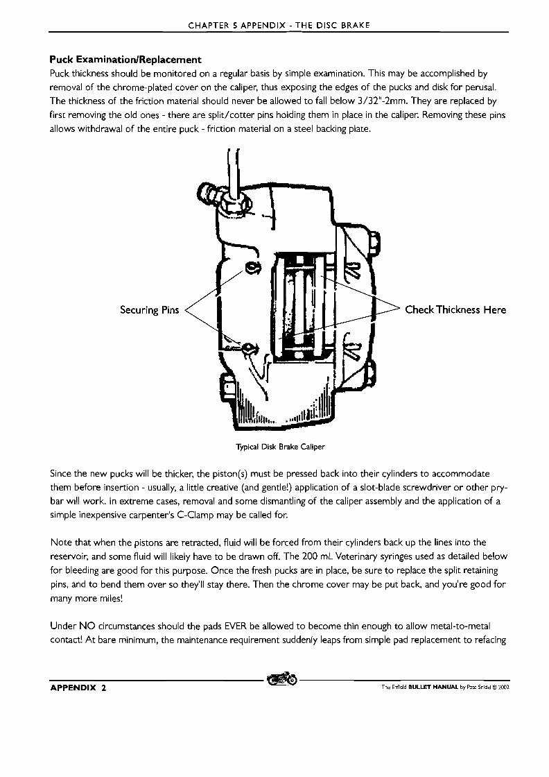
CHAPTER 5 APPENDIX - THE DISC BRAKE
Puck ExaminationlReplacement Puck thickness should be monitored on a regular basis by simple examination. This may be accomplished by
removal of the chrome-plated cover on the caliper, thus exposing the edges of the pucks and disk for perusal. The thickness of the friction material should never be allowed t o fall below 3/32"-2mm. They are replaced by
first removing the old ones - there are split/cotter pins holding them in place in the caliper. Removing these pins
allows withdrawal of the entire puck - friction material on a steel backing plate.
Securing Pins
Typical Disk Brake Caliper
CheckThickness Here
Since the new pucks will be thicker, the piston(s) must be pressed back into their cylinders to accommodate
them before insertion - usually, a little creative (and gentle!) application of a slot-blade screwdriver or other pry- bar will work. In extreme cases, removal and some dismantling of the caliper assembly and the application of a
simple inexpensive carpenter's C-Clamp may be called for.
Note that when the pistons are retracted, fluid will be forced from their cylinders back up the lines into the
reservoir, and some fluid will likely have to be drawn off. The 200 mL Veterinary syringes used as detailed below
for bleeding are good for this purpose. Once the fresh pucks are in place, be sure t o replace the split retaining
pins, and to bend them over so they'll stay there. Then the chrome cover may be put back, and you're good for many more miles!
Under NO circumstances should the pads EVER be allowed t o become thin enough to allow metal-to-metal contact! A t bare minimum, the maintenance requirement suddenly leaps from simple pad replacement to refacing
APPENDIX 2 The Enfield BULLET MANUAL by Pete Snidal O 2002
CHAPTER 5 APPENDIX - THE DISC BRAKE
the disk surface, and more likely to replacing the entire disk. This one is even more disastrous than running with
worn chains! If at all in doubt, replace the pads!
MAINTENANCE OF THE HYDRAULICS Periodically, some maintenance of the hydraulic systems will be required. In order of occurrence, these will be:
Monitoring Fluid Level This is a simple matter of routinely checking the level in each of the fluid reservoirs - there is one on the handlebar,
as part of the front brake lever control, and one on the frame behind and above the brake pedal pivot. It is very
important to maintain the level between the indicator lines - or, if no lines, to about I /4"-6mm below the top of
the reservoir. As the pads wear, more fluid will be required to compensate for the larger exposed volume of the
wheel cylinder(s). If the fluid level is allowed to drop to the point at which air is introduced into the system, much misery can result, as the air will have to be "bled" out, and this procedure can take much longer than a simple
check and topping-up occasionally. If the system begins losing brake fluid more rapidly than usual, check for:
Monitoring And Correcting Leaks The system should be examined on a regular basis for any sign of leakage - obviously, such leakage will be her- alded by loss of fluid from one or both of the reservoirs as mentioned above. Leakage points will be the master cylinder, a line or fitting between line components, or a wheel cylinder. Any leakage should be corrected imme-
diately. This may entail anything from a simple tightening up of a joint (avoid overtightening!) to a rebuild of a cylinder, involving honing and piston rubber replacement. (See details on leaks below
Correcting Air Problems 'The first sign of problems with air in the system will be sponginess in the control, likely with an improvement to
be gained by "pumping" it up. 'The cure for this is bleeding the air out of the system concerned, although in many cases the reason for air getting into it in the first place will also require correction.
Changing FluidlCleaning System Periodically, as in every year or two, the system should be flushed with clean brake fluid. Brake fluid is very cor- rosive to metal - and even to some extent, rubber - parts, and will dissolve impurities in itself. It is also hygro- scopic, meaning it will absorb water wherever possible, and water contamination will add to the destructive properties of the fluid on the system parts. The best way to replace the fluid is by pumping it in at the brake cylinder and drawing off and discarding the old fluid from the master cylinder reservoir during the process.
Here are the treatments in detail:
I .Air Problems Any air in this system will give trouble, since air, unlike hydraulic fluid (or any fluid) is compressible - pressure on
an air bubble will not result in definite movement of the brake parts, but rather will just compress and add a springiness to the feel of the system, as well as soaking up some of the very limited movement available. This air
will have to be "bled out" of the system in order to restore proper functioning. Since fluid should be replaced
yearly, or whenever any sign of pollution is present, you may as well completely replace all fluid in the brake sys- tem with fresh while you're at it.
The Enfield BULLET MANUAL by Pete Snidal O 2002 APPENDIX 3
CHAPTER 5 APPENDIX - THE DISC BRAKE
Bleeding'rhe System There are two major ways to bleed a hydraulic brake system. For the front brake system, with the large part of
it being the vertical run of the brake line(s), the far superior method is Reverse Bleeding. This involves forcing a
clean and air-free supply of fluid backwards through the system - introducing fresh fluid through the bleeder screw in the wheel cylinder(s), forcing any air upwards into the master cylinder reservoir. I t is particularly effec-
tive since air bubbles want to float upward anyway. Reverse bleeding requires an external pump of some kind t o
force the fresh fluid through the system.
"Forward bleeding" uses the master cylinder itself to pump fluid through the system, hopefully carrying any air away as well. The process involves multiple fillings of the master cylinder, which is used to pressure up the line and brake cylinder during multiple "blood lettings" of fluid through the bleed screw at that end. Although it is a satisfactory method for horizontally-arranged brake systems, such as disk rear brakes on some motorcycles, i t is
not very satisfactory for bleeding front disks on motorcycles.
Preliminary Caution! Brake fluid is ruinous to paint! Take all possible precautions to avoid contact with painted surfaces. If any gets on, get it off as quickly as possible. Flush with soapy water. This is particularly possible on your fuel tank if you
spill any from the front brake reservoir.
Here are the procedures in detail:
Reverse Bleeding I. Locate and remove the brake bleed screw - a hollow screw with a nipple on the end that looks a lot like a
grease nipple. Remove i t completely - use some penetrating oil, allow to soak, and administer a sharp light tap longitudinally to loosen the threads if necessary - be careful with this screw - it's small and easy to strip! Once the screw has been removed, clean it thoroughly. If it's necessary to use petroleum-based washing solvent, be sure t o finish by washing off all traces with methylated spirits/methyl hydrate/rubbing alcohol/methanol.
NO oil or grease must get near any brake parts! When cleaning, check that the hole is clear by blowing
through it. If it's plugged, work a small wire through the radial hole on the opposite (pointy) end of the screw into the main bore hole. Wire brush the threads and ensure that it works smoothly in the wheel cylinder.
Replace if necessary. Once it's clean, replace it in the cylinder, finger-tight.
A very suitable pump for reverse bleeding may be fashioned from a Veterinary IV Syringe - the 200 mL size is
ideal. These may be secured at most pharmacies. Unscrewing the needle off the front leaves a stub on which a 6-inch stub of 3/ 16" (4 mm?) soft plastic tubing will screw. The syringe may be filled by drawing brake fluid into it, and turning it upwards as you expel all the air. You'll also need a "transition tube" - a short piece of
5/ 16" neoprene tube, and a pair of spring clips for it. A pair of such tubes are supplied with aftermarket fuel filters at auto supply stores.
2. Screw a 6"/ 15cm piece of 3/ 16"-4mm clear plastic tube into the end of a 200 mL vet syringe. Draw a clean
supply of fresh DOT3 brake fluid into the syringe.
APPENDIX 4 The Enfield BULLET MANUAL by Pete Snidal O 2002
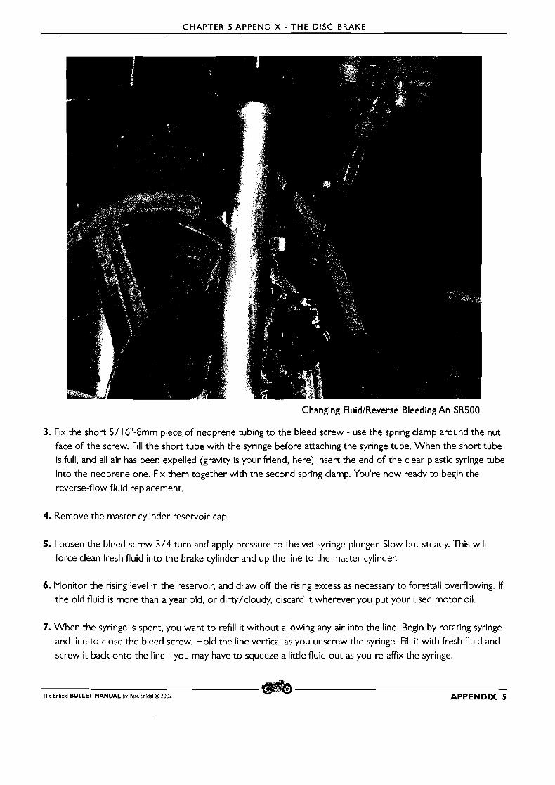
CHAPTER 5 APPENDIX - THE DISC BRAKE
Changing FluidIReverse Bleeding An SR500
3. Fix the short 5/ 16"-8mm piece of neoprene tubing to the bleed screw - use the spring clamp around the nut
face of the screw. Fill the short tube with the syringe before attaching the syringe tube. When the short tube is full, and all air has been expelled (gravity is your friend, here) insert the end of the clear plastic syringe tube
into the neoprene one. Fix them together with the second spring clamp. You're now ready to begin the
reverse-flow fluid replacement.
4. Remove the master cylinder reservoir cap.
5. Loosen the bleed screw 3/4 turn and apply pressure to the vet syringe plunger. Slow but steady. This will
force clean fresh fluid into the brake cylinder and up the line to the master cylinder.
6. Monitor the rising level in the reservoir, and draw off the rising excess as necessary to forestall overflowing. If
the old fluid is more than a year old, or dirty/cloudy, discard it wherever you put your used motor oil.
7. When the syringe is spent, you want to refill it without allowing any air into the line. Begin by rotating syringe
and line to close the bleed screw. Hold the line vertical as you unscrew the syringe. Fill it with fresh fluid and
screw it back onto the line - you may have to squeeze a little fluid out as you re-affix the syringe.
The Enfield BULLET MANUAL by Pete Snidal O 2002 APPENDIX 5

CHAPTER 5 APPENDIX - THE DISC BRAKE
8. Rotate syringe and line to loosen bleed screw. Continue forcing fresh fluid and drawing off excess from the
reservoir until the fluid in the reservoir is clean and air-free.
9. Once the fluid in the reservoir is clean and free of air bubbles, you may test the brake by tightening the bleed
screw on the wheel cylinder and operating the brake lever - you're looking for a hard but responsive "feel," with no sponginess. When done, draw out the reservoir down to the upper level indicator (or about 3/ 16"- 4mm from the top), and replace the lid.
If this procedure is not successful, it's time to rebuild or replace one o r the other cylinder.
Removing old/excess fluid. None too soon!
Forward Bleeding If no Vet Syringes are available, you can try forward bleeding. Here's how it's done:
To bleed air from the system, you will require a piece of tubing, most preferably clear, of proper size - and
preferably clear - to fit tightly over the nipple of the wheel cylinder bleed screw, a clean jar, a clothespin, a span-
ner/wrench for the bleed screw, and a container of fresh clean brake fluid. Begin by placing the jar on the shop
floor beside the wheel cylinder of the system with the air. Cut a piece of the tubing long enough to connect to
the bleed screw, loop upwards for I0 inches o r so, and then down into the jar. Put a half inch or so of clean
brake fluid into the jar, and use the clothespin to clip the tubing to side of the jar so that the tube stays below
fluid level. Remove the top of the reservoir and top up the fluid level. Replace the lid, but leave it loose. The object of the exercise is to pump fresh fluid from the reservoir through the system and into the jar, carrying
APPENDIX 6 The Enfield BULLET MANUAL by Pete Snidal O 2002
CHAPTER 5 APPENDIX - THE DISC BRAKE
along any air that it finds en route. The air will be seen exiting the bleed screw as bubbles, and the I 0 inches of upward tubing will provide a reservoir of fluid through which they will rise. Between pumps of the master cylin-
der, you will allow the bubbles to rise to the top of the loop, so that any fluid which is drawn into the cylinder
on the backstroke will be free of air.
Once set up, apply operating force to the master cylinder control - front brake lever - and open the bleed screw - with the tubing attached and looped into the fluid in the jar. As the control lever approaches bottom, close the
bleed screw. Let the system settle down for a few seconds, and repeat. After a pump or two, if not immediately,
air bubbles will be seen exiting the cylinder. Be sure t o check the reservoir level often - running out of fluid and
pumping fresh air into the system is contraindicated here. Once air stops exiting the cylinder, move onto the
next one, in the case of dual front brakes, or tighten the bleed screw completely (but not over!), top up the
reservoir, tighten up the top, and remove the tubing and jar. D o not save the bled brake fluid; each bleeding is a
good opportunity t o replace some old probably contaminated brake fluid with fresh stuff.
Since you're trying t o force air bubbles, which are considerably lighter than brake fluid, down the brake line, this method must be done as quickly as possible - the bubbles will tend to float back upwards between fillings and
pumpings. Once you've bled your system, you should be rewarded with a solidly-stopping hard control, and good brake control on the road. Monitor this situation, and if air problems rear their ugly heads within any kind of short time period, investigate the system carefully for leaks.
Down And Dirty This one has been known to work: Go as above, but with no tube on the bleed screw. Pressure the system with
the brake lever, release the pressure with the bleed screw, tightening before the pedal reaches bottom. IYaintaining level in the reservoir, repeat until no air is seen exiting the bleed screw. D o a final tighten on the
bleed screw and wash off the mess. Remember: Brake fluid is ruinous to paint!
2. LeakTrouble-Shooting Usually, a leak in the system will manifest itself, not only in air entering, but in fluid leaving, so in these cases the
leak is obvious. Air, however, being thinner than brake fluid, can sometimes enter leaky places that are still too tight for fluid t o exit. Thus air can sometimes enter without any tell-tale fluid leaks. At such times, it behooves
the unlucky owner to decide which cylinder t o replace first - the master cylinder or the wheel cylinder.
'The question t o ask is, "when I re-bleed, does the air start t o come immediately, o r does it take a few pumps?" Obviously, if it comes immediately, it has been building up in the wheel cylinder; if it has t o be forced down the line before showing itself, i t is coming in through a bad piston seal in the master cylinder.
RepairingIReplacing Cylinders Most manuals recommend installing exchange cylinders in cases of suspected trouble, but, if you can get a
rebuild kit, they're not usually that difficult. Worst-case scenario is slapping it back together and trading it in if you're unsuccessful, so the braver hearts may wish to try rebuilding. (However, check your prices! Rebuild kits,
consisting of a few pieces of rubber and a spring or two, have been known to cost almost as much as a rebuilt -
or even new! - cylinder.) Master cylinder rebuilds are as a rule more successful than wheel cylinder. Detailed
instructions may be found in the factory manuals.
The Enfield BULLET MANUAL by Pete Snidal O 2002 APPENDIX 7
CHAPTER 5 APPENDIX - THE DISC BRAKE
First, remove the cylinder under suspicion. If rebuilding is the choice, carefully dismantle it, saving all the parts in
a clean parts tray. Clean them up in methylated spirits/methyl hydrate/rubbing alcohol - NEVER petroleum- based cleaner or washing solvent. (The rubber parts are very sensitive to petroleum.) Carefully hone out all sur-
face problems in the cylinder - from dirt and gum to corrosion. Do the final cleaning with fresh brake fluid, and
reassemble, lubricating all rubber parts with fresh brake fluid. Reinstall the cylinder, tighten all the fittings (but
DON'T overtighten!), fill the system with fresh fluid, and bleed as described above.
Fluid Changing As mentioned above, hydraulic fluid is a nasty, corrosive, easily-contaminated substance that is best done with-
out. However, since Air Brakes have yet to be developed for motorcycles, and since disk brakes require more operating force than can be produced with simple cables and levers, and whereas disk brakes are so damn good, it looks as if we're stuck with the stuff. But we should do everything in our power to mitigate the harmful effects
o f it on our babies, and that means changing the fluid on a regular basis. Yearly is good - if you're unlucky
enough to live in a climate that requires putting baby up for the winter, why not do it with fresh brake fluid in
her veins? And if not, you're likely subject to more than your fair share of moisture in the air, and so you too
should change regularly, since brake fluid loves water more than your author loves Scotch and/or dark ale.
The procedure is simple enough. Just follow the procedure for bleeding air out, except in this case you're not
looking for air, and you want to pump through a couple of reservoir-fulls of fresh fluid. Be especially careful to maintain a level of fluid in the tubing above the bleed screw at all times - you don't want the system inhaling any air. Bleeding details are above
APPENDIX 8 The Enfield BULLET MANUAL by Pete Snidal O 2002

CHAPTER 6 - ENGINE WORK
CHAPTER 6 - ENGINE WORK
K I,,
i % r a , 4 / 4 r < = k&* 5 d . ~ &<
REPLACINGTHE BIG END OIL FEED QUILL BUSHING
Checking the Quill-style Oil Pressure Feed Bush First, a quote from Chapter 2: "The Bullet is unique in feeding oil pressure through a hollow feed bolt ( 1 73) into the rotating right-side crankpin via a hollow quill, sealed by a CW% gland-- situated in a recessed internal shoulder in
the end of the crankpin (75). Although this system has proven to be very reliable over many years, the cork is
somewhat primitive - most manufacturers of British machines began using modern spring-and-lip neoprene seals
by the end of the '60's - it is a potential weak point, and should be monitored on a regular basis. Oil change
intervals are a good time to check the quill bushing. (NB: the factory now supply an alternative quill bushing in neoprene,
but users report better performance and reliability-with the original cork ones.) --_ _ _ _ _ _ ___. ----- -------.
Checking may be accomplished by removing the quill feed bolt - in the center of the timing cover, above the oil
filter housing - be sure to have a catch tray to receive the oil which will drain from the timing cover cavity. Once
this is done, examination may be done with a strong light of the cork quill seal in the end of the crankpin. If there
is any sign of cracking, missing sections, etc., or if it appears to have a fairly loose fit around the quill, it should
be replaced. The knowledgeable Bullet owner will order replacement cork seals ten at a time, and always have - one o r two of the better ones he has soaking in clean oil, ready for replacing.
The Enfield BULLET MANUAL by Pete Snidal O 2002 59
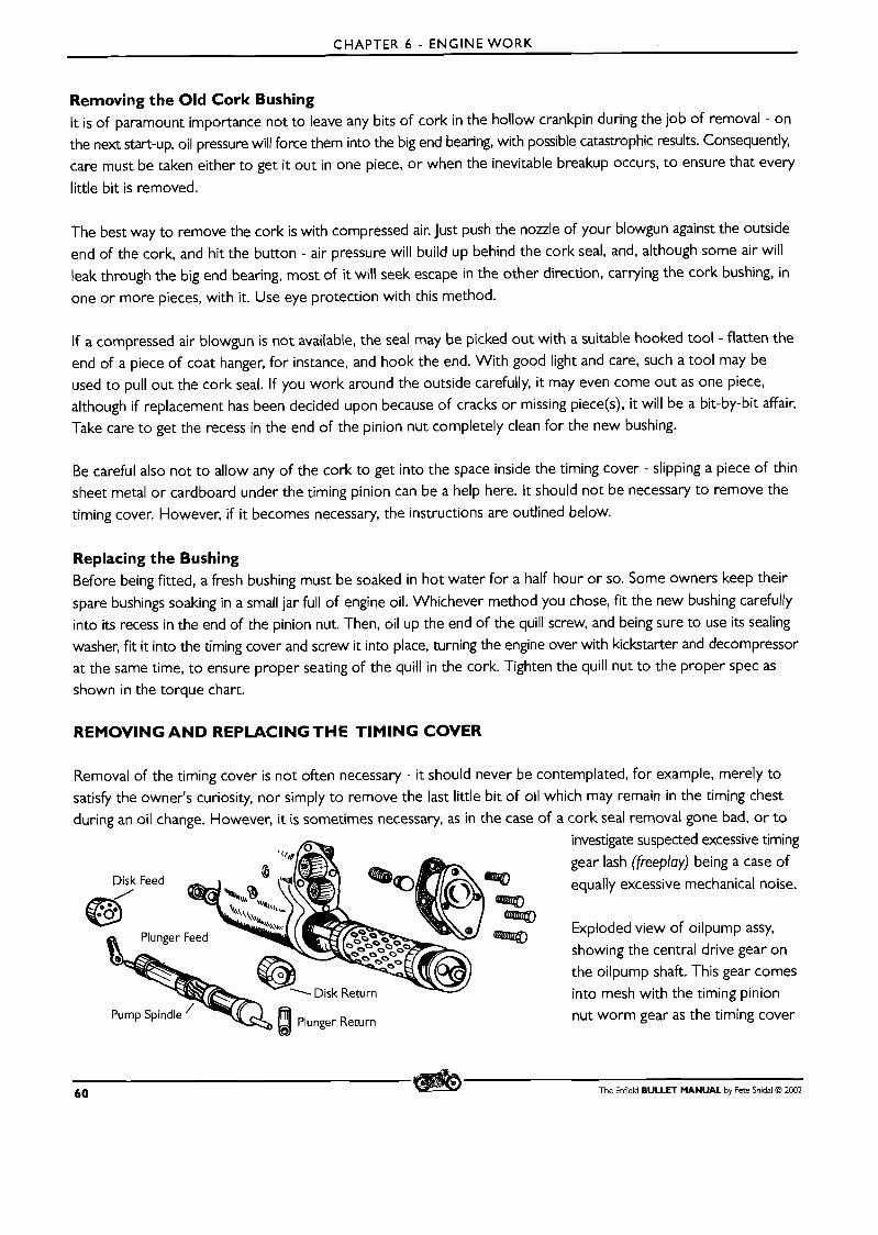
CHAPTER 6 - ENGINE WORK
Removing the Old Cork Bushing It is of paramount importance not to leave any bits of cork in the hollow crankpin during the job of removal - on
the next start-up, oil pressure will force them into the big end bearing, with possible catastrophic results. Consequently, care must be taken either to get it out in one piece, or when the inevitable breakup occurs, to ensure that every
little bit is removed.
The best way to remove the cork is with compressed air. Just push the nozzle of your blowgun against the outside
end of the cork, and hit the button - air pressure will build up behind the cork seal, and, although some air will leak through the big end bearing, most of it will seek escape in the other direction, carrying the cork bushing, in
one or more pieces, with it. Use eye protection with this method.
If a compressed air blowgun is not available, the seal may be picked out with a suitable hooked tool - flatten the end of a piece of coat hanger, for instance, and hook the end. With good light and care, such a tool may be used to pull out the cork seal. If you work around the outside carefully, it may even come out as one piece, although if replacement has been decided upon because of cracks or missing piece(s), it will be a bit-by-bit affair. Take care to get the recess in the end of the pinion nut completely clean for the new bushing.
Be careful also not to allow any of the cork to get into the space inside the timing cover - slipping a piece of thin
sheet metal or cardboard under the timing pinion can be a help here. It should not be necessary to remove the timing cover. However, if it becomes necessary, the instructions are outlined below.
Replacing the Bushing Before being fitted, a fresh bushing must be soaked in hot water for a half hour or so. Some owners keep their
spare bushings soaking in a small jar full of engine oil. Whichever method you chose, fit the new bushing carefully into its recess in the end of the pinion nut. Then, oil up the end of the quill screw, and being sure to use its sealing washer, fit it into the timing cover and screw it into place, turning the engine over with kickstarter and decompressor at the same time, to ensure proper seating of the quill in the cork. Tighten the quill nut to the proper spec as shown in the torque chart.
REMOVING AND REPLACINGTHE TIMING COVER
Removal of the timing cover is not often necessary - it should never be contemplated, for example, merely to satisfy the owner's curiosity, nor simply to remove the last little bit of oil which may remain in the timing chest
during an oil change. However, it is sometimes necessary, as in the case of a cork seal removal gone bad, or to investigate suspected excessive timing
gear lash (freeplay) being a case of
equally excessive mechanical noise.
Exploded view of oilpump assy,
showing the central drive gear on the oilpump shaft. This gear comes into mesh with the timing pinion nut worm gear as the timing cover
60 The Enfield BULLET MANUAL by Pete Snidal O 2002
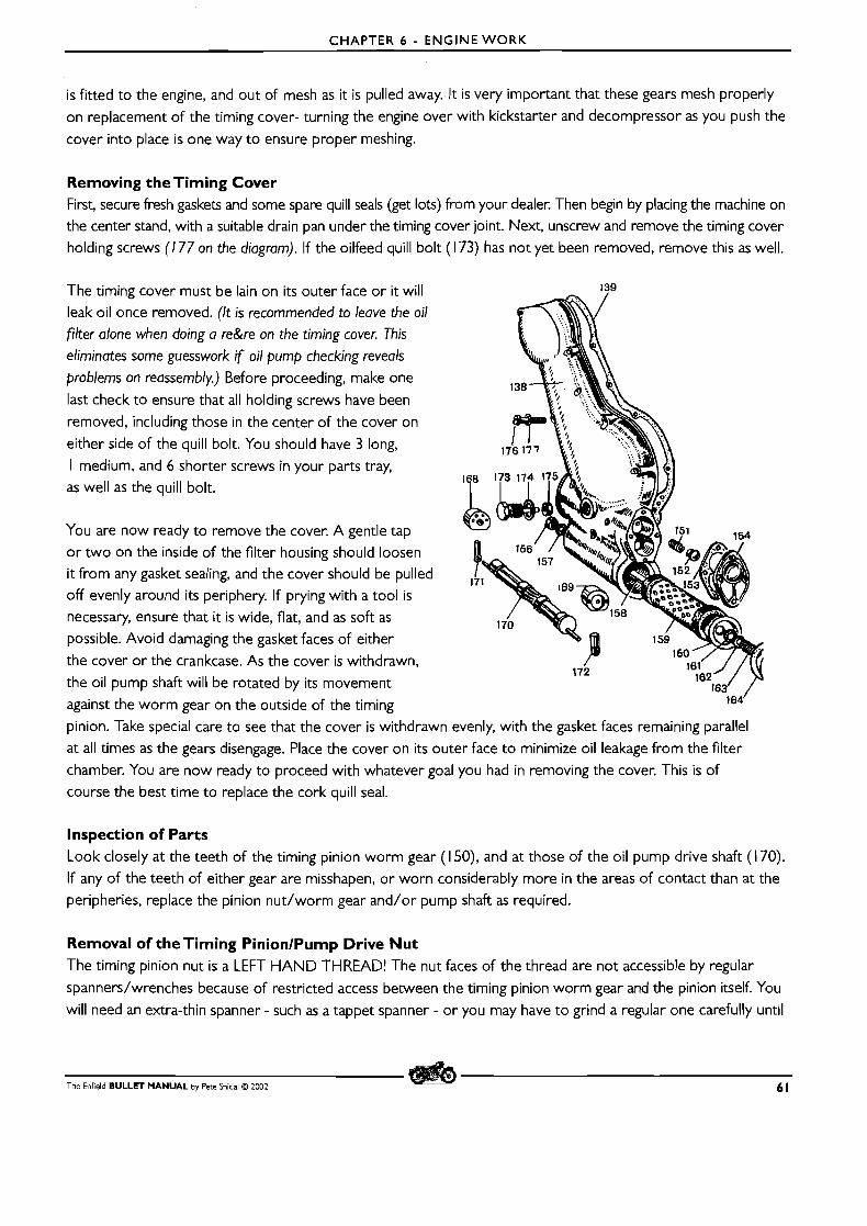
CHAPTER 6 - ENGINE WORK
is fitted to the engine, and out of mesh as it is pulled away. It is very important that these gears mesh properly
on replacement of the timing cover- turning the engine over with kickstarter and decompressor as you push the
cover into place is one way to ensure proper meshing.
Removing the Timing Cover First, secure fresh gaskets and some spare quill seals (get lots) from your dealer. Then begin by placing the machine on
the center stand, with a suitable drain pan under the timing cover joint. Next, unscrew and remove the timing cover
holding screws (1 77 on the diagram). If the oilfeed quill bolt (1 73) has not yet been removed, remove this as well.
The timing cover must be lain on its outer face or it will 139
leak oil once removed. (It is recommended to leave the oil
filter alone when doing a re&re on the timing cover. This
eliminates some guesswork if oil pump checking reveals
problems on reassembly.) Before proceeding, make one
last check to ensure that all holding screws have been
removed, including those in the center of the cover on
either side of the quill bolt. You should have 3 long,
I medium, and 6 shorter screws in your parts tray, as well as the quill bolt.
You are now ready to remove the cover. A gentle tap
o r two on the inside of the filter housing should loosen i t from any gasket sealing, and the cover should be pulled , off evenly around i ts periphery. If prying with a tool is
necessary, ensure that it is wide, flat, and as soft as
possible. Avoid damaging the gasket faces of either
the cover or the crankcase. As the cover is withdrawn, 172
the oil pump shaft will be rotated by its movement
against the worm gear on the outside of the timing
pinion. Take special care to see that the cover is withdrawn evenly, with the gasket faces remaining parallel
at all times as the gears disengage. Place the cover on i ts outer face to minimize oil leakage from the filter
chamber. You are now ready to proceed with whatever goal you had in removing the cover. This is of
course the best time to replace the cork quill seal.
Inspection of Parts Look closely at the teeth of the timing pinion worm gear (1 50), and at those of the oil pump drive shaft (170).
If any of the teeth of either gear are misshapen, or worn considerably more in the areas of contact than at the
peripheries, replace the pinion nut/worm gear and/or pump shaft as required.
Removal of the Timing PinionlPump Drive Nut The timing pinion nut is a LEFT HAND THREAD! The nut faces of the thread are not accessible by regular
spannerdwrenches because of restricted access between the timing pinion worm gear and the pinion itself. You
will need an extra-thin spanner - such as a tappet spanner - or you may have to grind a regular one carefully until
The Enfield BULLET MANUAL by Pete Snidal O 2002 6 1

CHAPTER 6 - ENGINE W O R K
REM Part No. PED 20 1 3 ST
iming Pinion Extractor
it will fit in the small space. O r secure Factory tool PD006ST - the special timing pinion nut spanner/wrench.
Removal of the pinion itself should be done with the factory puller. Be especially careful to place the drive key,
along with the timing pinion nut/oilpump drive gear in your parts tray.
Replacing the Timing Cover First, ensure that the gasket faces are clean and scratch-free. Use a fresh gasket if at all possible. If replacing the gasket, ensure that all traces of the old gasket have been scraped off the faces carefully. A gasket sealer, such as KoppercoteTM, Aviation Permatex IllTM, or silicone, if used sparingly, may be applied to both metal surfaces before fitting the cover.
If the oil filter cavity has been drained, this is a good opportunity to "prime" it - fill it with fresh oil - before
replacing the cover. If you choose this route, be careful not to let oil run from the filter cavity to the feed holes
in the filter housing (they are higher than the cover), thus polluting the gasket sealer, if any. Before refitting the
cover, ensure that the quill seal is in good condition, and that the quill itself is a tight fit into the cork.
Replacement is simply the reverse order of the above. You must be especially careful, however, to ensure that the pump drive gears are not presented to one another "point on," - turn the engine over slowly using the kick-
starter and decompressor lever, or a spanner on the crankshaft alternator nut, as the cover is pushed home onto
the crankcase. Tighten the fixing screws evenly and securely. Wipe any gasket sealant off the outside of the cases,
and ensure that the oil filter cover is secure if it has been disturbed. Oil the quill seal and cork before refitting
the quill bolt and its sealing washer into the timing cover. Do not tighten the bolt fully until after the first startup.
On Startup After timing cover service, ensure that the oil pumps are performing properly. Finger-tighten the quill bolt until i t
stops, then back it off a half turn. Place a catch tray under the timing cover. Loosen off the rocker oil feed union
(be sure to hold the lower fitting with a suitable spanner so that it cannot turn in the case, allowing the line to twist)
fitting a turn or two. Then, start the machine, and allow it to tick over while observing the two oil unions. The
quill nut should be the first to drool oil under pressure, coming from the pump through the filter. If the filter
cavity was empty on reassembly, it will take a minute or two to fill before oil starts to flow. When oil does flow,
wait until any bubbles stop appearing, then tighten the cap screw.
62 The Enfield BULLET MANUAL by Pete Snidal O 2002
CHAPTER 6 - ENGINE WORK
The rocker oil feed is fed by the scavenge pump pulling oil from the crankcase sump, so oil won't appear until it
has been through the big end and begins to accumulate below. When oil appears at the pipe union, tighten up
the union. For final tightening, be sure to hold the lower in-case fitting as described above.
Trouble Shooting In the event that oil flow does not appear after a minute or two of running, shut down the engine and investigate.
First, pull off either of the two pump covers - this may mean removing the exhaust pipe. Be careful no to lose
the tension spring o r end pad - and carefully place the parts into a clean parts try. Then, supporting the pump
body by pressing it into its housing with a finger, check to see that it turns with the engine. If not, remove the
pump body and check to see that the eccentric on the end of the pump shaft turns with the engine. If not,
remove the timing cover and investigate.
Do not run the engine without verifying that oil is being fed to big end and rockers, other than for short no-load tests.
Oil Pump Operation The pumps operate by virtue of the pump bodies acting as valves by being turned in their cavity, exposing different ports at the rear of their cavities at different positions in the cycle, and the simultaneous stroking of the plunger
in the pump cylinder. On the pump intake stroke, the pump cylinder is opened to its intake port - from the tank
or sump - through the lining up of the ports in the pump body and the rear of its cavity in the timing cover. As
the body is turned by the eccentric on the end of the drive shaft, the piston is simultaneously drawn out of the
cylinder, drawing oil through the port into the cylinder. As the end of this intake stroke is reached, this port is
closed by rotation of the body, and the cylinder outlet port is exposed to the cavity outlet port - to the filter
and quill feed, or to the rocker feed line, as the further rotation of the eccentric forces the piston into the cylinder,
forcing oil into the outlet passage.
The pumps are quite simple in design, and, providing they are turning, can only be adversely affected by :
Plugged pickup screens - in the drainplugs of sump and oil tank
w Poor spring tension Swarf (junk) impeding the seal of the pump body against the back of i ts housing
w Poor sealing due to a decayed fit between pump and cavity Excessive pump clearances,
w Drive failure
Stopped or leaking feed lines, which are integrally cast in the crankcase halves, from either the oil tank (pressure
pump) or the sump (scavenge pump).
In the case of any of these problems, the solutions are self-evident: cleaning o r replacement. In some cases, it
will be helpful to lap in the pump to the rear of the cavity with fine valve grinding compound. If this is done, BE
CERTAIN to wash the pump cavity and all parts thoroughly with washing solvent, and then hot soap and water
before reassembling, since grinding compound is doubleplus-anti-recommended (Newspeak for "don't do it!") or
lubrication of engine parts in general, and oilpump parts in particular. See your Factory Tools Manual for a look at pump lapping tools PD034ST and PD035ST.
The Enfield BULLET MANUAL by Pete Snidal O 2002 63
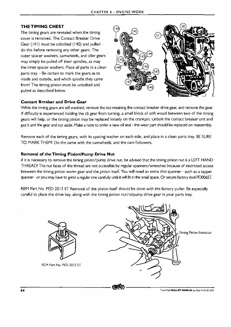
CHAPTER 6 - ENGINE WORK
THETIMING CHEST The timing gears are revealed when the timing
cover is removed. The Contact Breaker Drive
Gear ( I 4 1 ) must be unbolted (1 40) and pulled -
do this before removing any other gears. The outer spacer washers, camwheels, and idler gears
may simply be pulled off their spindles, as may the inner spacer washers. Place all parts in a clean
parts tray. - Be certain to mark the gears as t o
inside and outside, and which spindle they came from! The timing pinion must be unbolted and pulled as described below.
Contact Breaker and Drive Gear While the timing gears are still meshed, remove the nut retaining the contact breaker drive gear, and remove the gear. If difficulty is experienced holding the cb gear from turning, a small block of soft wood between two of the timing
gears will help, or the timing pinion may be replaced loosely on the crankpin. Unbolt the contact breaker unit and put it and the gear and nut aside. Make a note to order a new oil seal - this wear part should be replaced on reassembly.
Remove each of the timing gears, with i ts spacing washer on each side, and place in a clean parts tray. BE SURE
T O MARK THEM! Do the same with the camwheels, and the cam followers.
Removal of the Timing PinionlPump Drive Nut If it is necessary to remove the timing pinion/pump drive nut, be advised that the timing pinion nut is a LEFT HAND THREAD! The nut faces of the thread are not accessible by regular spanners/wrenches because of restricted access between the timing pinion worm gear and the pinion itself. You will need an extra-thin spanner - such as a tappet spanner - or you may have to grind a regular one carefully until it will fit in the small space. Or secure factory tool PD006ST.
REM Part 110. PED 20 13 ST Removal of the pinion itself should be done with the factory puller. Be especially careful to place the drive key, along with the timing pinion nut/oilpump drive gear in your parts tray.
REM Part No. PED 20 13 ST
64 The Enfield BULLET MANUAL by Pete Snidal O 2002
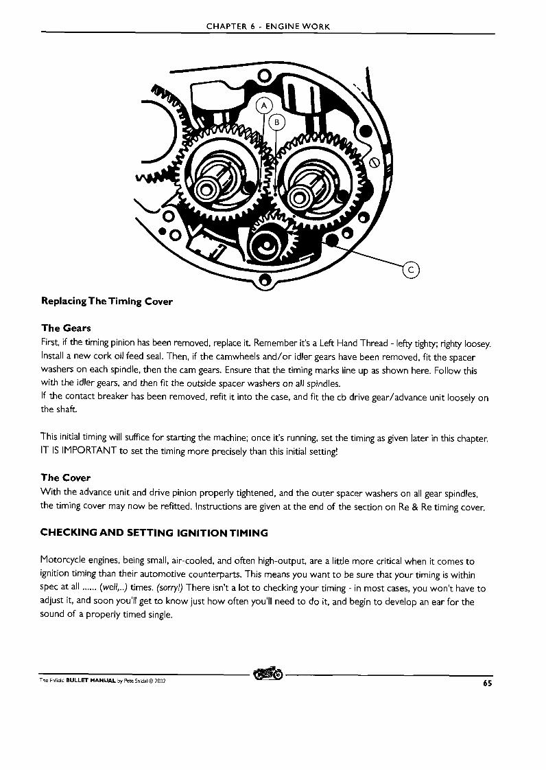
CHAPTER 6 - ENGINE W O R K
Replacing The Timing Cover
The Gears First, if the timing pinion has been removed, replace it. Remember it's a Left Hand Thread - lefty tighty; righty loosey.
Install a new cork oil feed seal. Then, if the camwheels and/or idler gears have been removed, fit the spacer washers on each spindle, then the cam gears. Ensure that the timing marks line up as shown here. Follow this with the idler gears, and then fit the outside spacer washers on all spindles.
If the contact breaker has been removed, refit it into the case, and fit the cb drive gearladvance unit loosely on the shaft.
This initial timing will suffice for starting the machine; once it's running, set the timing as given later in this chapter.
IT IS IMPORTANT to set the timing more precisely than this initial setting!
The Cover With the advance unit and drive pinion properly tightened, and the outer spacer washers on all gear spindles,
the timing cover may now be refitted. Instructions are given at the end of the section on Re & Re timing cover.
CHECKING AND SETTING IGNITION TIMING
Motorcycle engines, being small, air-cooled, and often high-output, are a little more critical when it comes to
ignition timing than their automotive counterparts. This means you want to be sure that your timing is within spec at all ...... (well,..) times. (sorry!) There isn't a lot to checking your timing - in most cases, you won't have to
adjust it, and soon you'll get to know just how often you'll need to do it, and begin to develop an ear for the
sound of a properly timed single.
The Enfield BULLET MANUAL by Pete Snidal O 2002 65
CHAPTER 6 - ENGINE WORK
The Objective Here's what we're trying to do: The piston comes up on the compression stroke every second time around,
pushing a cloud of fuel/air mixture up into a small space under the head - the combustion chamber. The idea of the internal combustion engine is to get this compressed mix to light up, and to burn, thus expanding and bring-
ing about the Power Stroke, in which the piston is forced back down the cylinder, making the wheels turn. The end of the power stroke is brought about by the release of this pressure by the opening of the exhaust valve on or about the bottom of the power stroke. What lights up the compressed mixture is the spark plug, and the fir-
ing time, relative to the position of the piston, is controllable by adjustment of the spark advance - setting your ignition timing. The spark fires, in points systems, when the points open - they close soon after, and what hap-
pens during the time they're closed is another story, beyond the scope of this lecture. What's important to us
just now is that each time they open, a spark is sent to the plug.
Three Possibilities:
Spark is too soon: The "flame front" of the expanding gasses will meet the piston while it's still on the way up.
This will be signalled by a subtle sound of marbles rolling around in the motor, and is known as "ping." The pre-ignition thus signalled will cause extreme overheating of the piston crown, and the resultant excessive pressures will work with this to blow an actual hole in your piston! This is not generally considered a Good ThingTM. Spark is too late: The flame front has to "chase" the descending piston down the cylinder, catching up with it at some time, resulting in some burning of the fuel. The exhaust valve opening will be greeted by a burn that is
still well in progress, with lots of burning left to do in the exhaust pipe, resulting in overheating of the entire engine, and signalled by a flatter exhaust note, burning of the chrome on the pipe, and generally poor efficiency. Retarded timing will also burn your exhaust valve, necessitating a valve job at minimum. Just Right. The best, needless to say. Characterized by that "snarl of a well-tuned single," at least to some degree,
the best mileage and power, the minimum pipe burning, and the longest engine life. Well worth checking once in a while to make sure you're there.
Broadly speaking, there are two ways to do this - static, and dynamic, or not running, and running. The easier, and for the novice, surer way is statically - you rotate the engine, while monitoring the position of the piston,
and check to see at what piston position the spark is set to go off. But, although this is the method for initial set- ting, it is not as accurate as Ping Timing, which will be dealt with later.
Tools and Materials All you need for tools will be a test light - a 12V bulb with wires and clips on the ends of the wires; it can be a commercial product or one you make yourself, and a "timing stick" - a piece of straight coat hanger wire, which you will calibrate by marking two spots with a file or hacksaw blade. You will also need a screwdriver and a feeler gauge set.
Setting the Point Gap First, you want to set your point gap to factory specs. Do this by removing the cover of the contact breaker
housing - found at the top of the timing chest, under the carburetor and behind the cylinder. Inside you will find
the points themselves. The distance between them is changed by rotation of the breaker cam, which opens and
closes them as well.
66 The Enfield BULLET MANUAL by Pete Snidal O 2002

CHAPTER 6 - ENGINE WORK
Replacing the Point Set If any signs of burning or pitting are present, the point set
should be replaced before proceeding with gap setting or
re-timing. Removal of screw (F) will allow withdrawal of
the set from the advance plate, and then the electrical
connection may be unscrewed and the points replaced.
Be particularly careful to reconnect the electrical setup exactly
as found - if the wire is allowed to connect electrically
with the points plate, no sparks will be generated on
reassembly. Test electrically to ensure that when points
are open, and coil wire is not yet connected, there is no path
to ground from the coil wire terminal. (Non-stationary point.)
Once the new point set has been installed and connected, proceed with adjustment and/or timing as below.
What About the Condenser? The function of the condenser is two-fold; to aid in flux buildup in the ignition coil primary at the moment of point closing, and to "buffer" the primary sparking at the time of their opening. You can get a general idea of the condition
of the capacitor by observing the points with the engine running. If a lot of sparking occurs, the capacitor is not
doing its job. The "cap' may also be shorted - in which case there will be no open circuit across open points with
coil disconnected. Condenser trouble is rare; there is no real reason to replace the condenser with each point
replacement, although this is common in rich wasteful countries.
For an understanding of how the points operate, pull the decompressor and kick the engine over and neutral as you
watch the operation of the points open and close. When they close, with the ignition on, there is an electromagnetic
build-up in the primary (1 2V) section of the ignition coil. When they open, the breaking of the primary circuit brings
about a sudden collapse of the magnetic field, which induces a high-voltage (about 15,000V) in the secondary
circuit, feeding a single spark to the spark plug, and igniting the fuel mixture in the cylinder at that time. There is
a thing called "back emf' which occurs at point opening, which the condenser is there to soak up. This restricts
point damage due to arcing, and also adds to the buildup in the coil each time the points close - the "dwell" period.
In simpler terms, the spark occurs at the precise moment the points open.
Examination of the "breaker plate," on which the point assembly is mounted, will reveal
the points adjustment lock screw (F), and the adjustment mechanism - setting one side of
a slot screwdriver blade between the dimples on the breaker plate, and the other side of
the blade into the slot in the stationery points plate (At point A) will allow twisting to adjust
the point gap - the relative distance between the moving and stationary contact points.
First, rotate the engine (use the decompressor) until the points open. Using a strong light,
check the condition of the contacts. If they show any burning or pitting, they may be
lightly dressed with a nail file or fine emery board, but they should be replaced ASAP. Order two pairs, one for replacement, and one for a spare. (I always carry a spare set in
my toolbox; points have been know to become suddenly nonconductive.)
The Enfield BULLET MANUAL by Pete Snidal O 2002 67
CHAPTER 6 - ENGINE WORK
After inspection, with them still at maximum opening, insert a .O I5"/0,35-0,40mm feeler gauge blade between them. There should be just a slight resistance to the passage of the blade. If it's too loose or tight, you'll want to
adjust the gap. Loosen off the lock screw and adjust the distance until the feel is correct. Then tighten the lock
screw and replace the cover.
Checking Ignition Timing Since variations of point gap will change ignition timing, first the gap must be checked and/or set, as above.
Then, the timing may be checked and/or set in one of two ways:
Static Timing - in The Shop This is difficult, and takes no consideration of variation between machines, fuel, engine condition, or rider practices. This is done by patiently fiddling with timing sticks, rulers, dial gauges, etc., and riding off into the sunset, having no sure idea that it is correct.
This is a shop procedure, done with the engine not running. The first step is to check and adjust your breaker points as described earlier. The next step is to verify that the points open at the exact point of piston movement
necessary for correct ignition timing. You will determine the instant of points opening using a 12V test lamp, and the piston position using a timing stick.
The Timing Stick: I. Put the machine on the center stand, or otherwise raise the rear wheel. Find the compression stroke by
moving the kickstarter until compression is felt. Remove the spark plug, being careful first to clean the area around the plug hole.
2. Prepare the timing stick. Take a 6" piece of straight coat hanger, welding rod, or similar material. With the machine in top gear, insert the wire through the plug hole, as close to straight down as you can get it. Then rotate the rear wheel in a forward direction until the wire is forced upwards. When it gets as far up as it gets, rotate the wheel back and forth until you get the "feel" for Top Dead Center-" Then, make a note of a spot on the timing stick that corresponds to some spot on the cylinder head - the top rim of the spark plug hole is a good one. Mark this with your thumbnail, withdraw the timing stick, and mark this TDC point with the file or hacksaw blade.
3. IVow, all you need to do is to mark the proper advance distance on the stick, above the TDC mark. The factory
recommendation is I /32"-0,8mm - this is the advance for fully retarded ignition, since the centrifugal advance unit will not be advanced at 0 rpm.
Spark advance specs are given as before TDC, either in degrees of crankshaft rotation, or in actual piston travel
distance - the spec we'll be using here. You may want to keep the stick in your toolbox for future use.
Finding the Point of Spark Occurrence For this, you'll want to use the test light. When the points are open and the ignition is on, there will be a voltage present across the points. When the points are closed, this voltage will drop to 0. So you want to connect one side of your test lamp to the wire from the coil to the points, and the other to ground (the other side of the points.)
68 The Enfield BULLET MANUAL by Pete Snidal O 2002
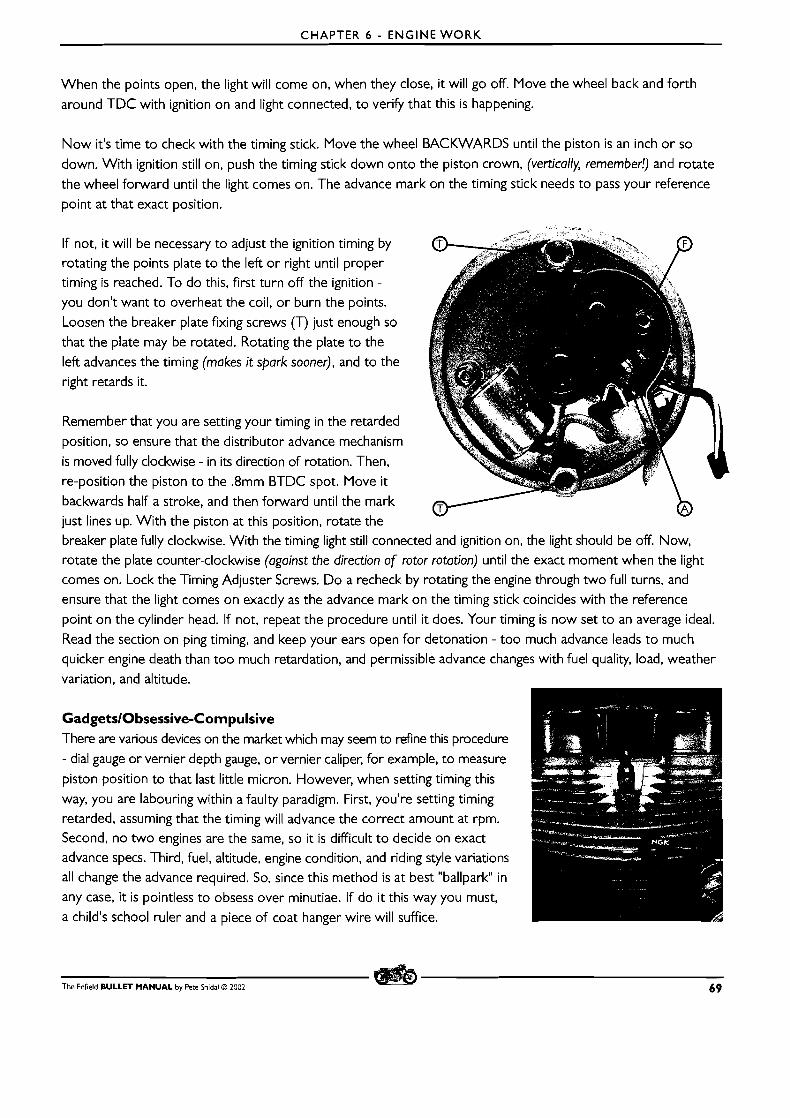
CHAPTER 6 - ENGINE WORK
When the points open, the light will come on, when they close, it will go off. Move the wheel back and forth
around TDC with ignition on and light connected, to verify that this is happening.
Now it's time to check with the timing stick. Move the wheel BACKWARDS until the piston is an inch or so
down. With ignition still on, push the timing stick down onto the piston crown, (vertically, remember!) and rotate
the wheel forward until the light comes on. The advance mark on the timing stick needs to pass your reference
point at that exact position.
If not, it will be necessary to adjust the ignition timing by rotating the points plate to the left or right until proper timing is reached. To do this, first turn off the ignition -
you don't want to overheat the coil, or burn the points.
Loosen the breaker plate fixing screws (T) just enough so
that the plate may be rotated. Rotating the plate to the
left advances the timing (makes it spark sooner), and to the
right retards it.
Remember that you are setting your timing in the retarded
position, so ensure that the distributor advance mechanism
is moved fully clockwise - in its direction of rotation. Then,
re-position the piston to the .8mm BTDC spot. Move it
backwards half a stroke, and then forward until the mark
just lines up. With the piston at this position, rotate the breaker plate fully clockwise. With the timing light still connected and ignition on, the light should be off. Now,
rotate the plate counter-clockwise (against the direction of rotor rotation) until the exact moment when the light comes on. Lock the Timing Adjuster Screws. Do a recheck by rotating the engine through two full turns, and
ensure that the light comes on exactly as the advance mark on the timing stick coincides with the reference
point on the cylinder head. If not, repeat the procedure until i t does. Your timing is now set to an average ideal.
Read the section on ping timing, and keep your ears open for detonation - too much advance leads to much
quicker engine death than too much retardation, and permissible advance changes with fuel quality, load, weather
variation, and altitude.
GadgetslObsessive-Compulsive There are various devices on the market which may seem to refine this procedure
- dial gauge or vernier depth gauge, or vernier caliper, for example, to measure
piston position to that last little micron. However, when setting timing this
way, you are labouring within a faulty paradigm. First, you're setting timing
retarded, assuming that the timing will advance the correct amount at rpm. Second, no two engines are the same, so it is difficult to decide on exact advance specs. Third, fuel, altitude, engine condition, and riding style variations
all change the advance required. So, since this method is at best "ballpark" in
any case, it is pointless to obsess over minutiae. If do i t this way you must,
a child's school ruler and a piece of coat hanger wire will suffice.
The Enfield BULLET MANUAL by Pete Snidal O 2002 69
CHAPTER 6 - ENGINE WORK
DYNAMIC TIMING - RUNNING This is easier to do, and takes all factors into consideration. The idea is to check for the sound of "ping"/detonation
on the road, under actual riding conditions, and to fine-tune the timing around this sound. In cases of complete re-setting of timing, it involves first doing a rough static timing, and then fine-tuning through roadtesting. I t takes
an ear to hear the sound of the ping, however - some owners may be hard of hearing - and i t must be done in relatively quiet conditions - expressways are out for this one.
Ping Timing Static timing sets the ignition timing when the motorcycle isn't even running. The more astute reader may have had the thought occur that conditions must change when it is running, and especially hot and under load, and that it
would be a wondrous thing indeed if natural compensations took place for the changes. And he would be correct.
There is a better way to set your timing. Since there is a centrifugal advance unit in the contact breaker drive,
the actual relative timing of the spark will change up to a certain point with engine rpm. Furthermore, there are
variations in individual engines, fuels, and operating styles. The very best way to set ignition timing would be under load, with proper analysis equipment, varying the timing until it told us we had arrived at the "magic spot."
This would require a chassis dynamometer, and such test equipment as an exhaust pyrometer. Fortunately, there is a way we can check our timing under load without all this, and that is by "ping" timing.
Ping, or preignition knock, or detonation knock, is the term for a knocking sound which accompanies excessive spark advance in an engine under load. It is easily detected with the human ear, and sounds like marbles rattling
around in the cylinder head. I t increases with load and spark advance, and goes away with decrease in load (throttle) and spark retard. If the machine is test ridden under load, and the spark is progressively advanced in
small increments until knock can be heard at higher loads (higher throttle openings in 3rd or 4th gear), then the ideal spot can be found by working backwards from there until the knock can no longer be brought on, then just a bit more
retarded than that. This is the spot at which the lowest exhaust temperature and best power will be found.
IMPORTANT SAFETY N0TE:The safety considerations of this on-road vehicle testing are very important. Before testing, pick a spot with as little traffic as possible, and an upgrade so that the engine may be loaded without excessively high speeds (and confusing wind noise) When testing, be especially careful to observe all road rules - signalling, rearward traffic awareness, and pulling into safe areas. Remember, other drivers will have no idea what you're up to!
The first advantage to Ping Timing is that you don't have to be so fussy during initial setting. Just set with advance unit retarded (rotor to the lefi, against the direction of normal rotation - the centrifugal unit springs will hold it there),
piston on TDC on compression stroke, and rotate the breaker plate fully clockwise until the points close, then back anti-clockwise (against the normal rotation) until the points just open - a test light is still the best way,
although the ammeter method (ammeter will drop back as points open with ignition on.) Tighten the lock screws.
This will give you a "ballpark" setting which will allow you to start the machine and take it for a test ride.
Checking for "Ping" Take it for a warm-up cruise to your test site. This will be a place where you can ride while varying your throttle
opening, and which is relatively quiet, so that you will be able to listen for "ping," or detonation knock. Once
70 The Enfield BULLET MANUAL by Pete Snidal O 2002

CHAPTER 6 - ENGINE WORK
there, get the machine t o mid-range rpm in 3rd or 4th gear, and increase the throttle opening t o 1 / 2 to full
throttle, listening for mechanical noise from the engine. This is the power setting for "ping testing."
If you don't hear any detonation, you will have to advance
the ignition in small stages until you do, to establish a base
line. This means loosening the breaker plate lock screws (T), and rotating the breaker plate anti-clockwise (to the lefl) a
bit. Then, tighten the screws, start the bike, (put the cover
and cover screws in your pocket for the time being) and
re-check. Do this until you get some "ping." Then, retard it
in successive small stages until you can no longer bring up
any ping. Then retard one more small stage after that, and tighten up the timing screws. Turn breaker plate clockwise to counter ping; counter-clockwise to get some. It is not
harmful t o the machine to ride it back t o your place of work before retarding the timing - just avoid the ping by
reducing throttle opening, or running at higher rpm until the noise disappears. Or you can adjust the timing at roadside. What you are listening for is a rattling sound from the cylinder head area, which increases with throttle c I t has been compared to the sound of marbles rattling around
is that it falls off with throttle opening, and appears best at Ic
)pening, and goes away as the throttle is cut back. in the cylinder head. The unmistakable characteristic
lwer rpms.
Ping will also vary with carburetor mixture, or jetting. A leaner mixture (smaller jets, or lower altitude) will bring
on pre-ignition, requiring enrichening the mixture, retarding the spark, or both. A richer mixture, or higher alti-
tude, will permit a greater spark advance. This means that ignition timing may have to be changed with altitude dif-
ferences. If you ride in mountain country, in a wide variety of altitudes, ( 1 000 fl/300 mtn makes a difference) you may have t o set your timing for best performance at the lower altitude. If you are touring, and encountering
areas in which fuel quality varies, be sure t o listen for detonation, and stop and re-tune whenever you detect it.
I used t o keep my engines set so that I could always get ping when I hit the throttle harder than I usually do, at
low rpm. But it turns out that this setting is too advanced - you have to back off just past that point, so you have no way of checking except t o over-advance. If you had t o over-advance a lot, you know you were too retarded; if ever you hear ping, you know you're too advanced. This may appear to be a bit more trouble than setting the timing in the shop, but the advantages far outweigh the extra trouble.
The Enfield BULLET MANUAL by Pete Snidal O 2002 7 1
CHAPTER 6 - ENGINE WORK
TOP END OVERHAUL
Do You Need A Top-End Job? If it works, don't fix it - this is an adage to keep in mind at all times when about to work on anything. But if your
symptoms include poor compression, then top end work is indicated. First, check the compression.
Checking Compression 'The very best way to check compression is by the Leakdown Method. The piston is brought to TDC on the
compression stroke - both valves closed. The spark plug is removed and replaced with an air fitting connected to an air source with a pressure gauge teed into the line. Air is introduced into the cylinder via a valve from the air source (a tank of compressed air is good), and once the valve is closed, the combustion chamber should hold air pressure for some time - the shorter the time period, the worse off the engine. While the air is being applied, it is often helpful to listen at the carburetor intake and at the exhaust pipe , as well as at the crankcase breather, for escaping air - a hiss from any of these will tell you what's leaking.
NB: the Bullet has one further little wrinkle - the decompressor valve may be leaking - this will permit the escape
of air into the exhaust system. If your only leak seems to be from the exhaust pipe, remove the decompressor
valve, disassemble, and lap the parts in with lapping compound, using a screwdriver in the slot in the valve head to turn it back and forth. Reassemble and check again before going any further with the top end work - you may
have cured your problem!
A leakdown test kit is a worthwhile addition to the shop, and it is recommended that you build, buy, borrow, or rent one to check your top end if you are not entirely sure that you have a leakage problem. There are two other less reliable methods to check, however, and a conclusive indication from either one of these may also be worthy
of consideration. Caution: be sure your valve clearances aren't too tight!
First, the kickstarter. Standing on the kickstarter on compression stroke should support your weight without the engine turning over - at least if the engine has been run in the past few minutes, and the oil is up where it needs to be. Comparison with a known-good machine is helpful here also, obviously such parameters as rider weight, compression ratio, etc. will make a difference. But if you once could, and now it just rolls right over, you know
you likely have a top-end problem. This one can be used in conjunction with having another person listen at the
three places mentioned above as well.
And finally, an automotive-type compression gauge. Once again, comparison with a known-good engine is pretty well a necessity, since the parameters of kick-over speed, the gauge itself, etc. will make a difference. A screw-in
type of compression gauge, and a number of kicks before accepting the reading are good ideas here as well. It should be borne in mind, however, that an automotive type gauge is intended to use to compare readings between cylinders on multi-cylindered auto engines, and the lack of a "base line" for comparison makes decision difficult.
If no compression at all can be detected, though, you still know you have a problem.
"Wet And Dry" Compression Testing If two successive compression tests are done, with the second done after removing the gauge and oiling the cylinder, a comparison between ring sealing and valve sealing may be made. Remove the compression gauge,
72' The Enfield BULLET MANUAL by Pete Snidal O 2002
CHAPTER 6 - ENGINE WORK
give the cylinder a few good squirts of oil from an oil can, then kick it over a few times to distribute the oil in
the rings. Then do the second compression test. If an improvement is attained, it is reasonable to assume that
excessive ring clearances are losing compression for you, and that re-ringing will likely be required. You will of
course do the valves as well, while you have the top end apart.
Periodically, it is necessary to take the top end - the cylinder head and cylinder barrel - off, and examine the clearances
between various parts, as well as the valve sealing. While we're in there, we also clean off all the carbon that has
built up in the combustion chamber - this should not be excessive, unless you've been running too rich, or burning
too much oil - generally, an engine that isn't smoking won't require specific teardowns just for carbon removal.
O n the other hand, if it's smoking too much, it will.
Excessive carbon buildup on the combustion chamber surfaces results in the development of "hot spots," which
bring about pre-ignition, also called detonation. These must be removed periodically by the process of "decarbonizing - removal and dismantling of the cylinder head, and removal of the carbon build-ups in the combustion chamber
and (mainly) exhaust and intake ports, as well as on the valves.
You can get an idea of the state of carbon buildup in your engine by removing the spark plug and bringing the
piston close to the top. Then, using a suitable tool, such as a small (but long) screwdriver, attempt to scrape a
spot off the top of the piston, using a strong light to keep track of your progress. If you find there is a buildup
that can be scraped down to make a groove of .025-.050" - ,06- 1.2mm, it is time for decarbonizing. Plan to have
your valves reground and the seats refaced while you're in there.
An Explanation of Clearances In order for the piston to slide up and down in the cylinder properly, i ts outer diameter must be smaller than that
of the bore of the cylinder. (The piston, by the way, is actually oval-shaped, with the distance across the "skirts" - front
to back at the bottom - being the greatest.) If the difference, or space, called clearance, is too great, a condition called
"piston slap" will attain, and the piston will get noisier and wear more rapidly until it fails. If the clearance is too small,
the piston will overheat and expand until it gets too tight in the bore, often seizing at the high temperatures developed. In this case, allowing the engine to cool will often allow restarting, but the piston will have "galled" the
cylinder walls, and the engine will have to be dismantled and properly put back together. It is not a good idea to
continue to operate a machine which has seized and come unstuck after cooling down. Typical cold piston clearance
is in the neighborhood of .002/.05mm when new, and maximum allowable wear would create a clearance in
the neighborhood of .008"/.2mm. Beyond this, piston replacement, or even reboring and fitting of an oversize
piston is required.
Although there is a certain amount of sealing between the piston and the cylinder, there would not be nearly
enough to allow the engine to run without the additional sealing provided by the piston rings - these expand and
contract as the piston goes up and down, conforming to minute variations in cylinder diameter, as well as providing for differences as temperatures change. The rings have a gap at their ends, starting at .O I5"/.4mm when new. As
the rings wear on their outside edges (the diameter), the gap (the circumference) increases by a factor of pi, and
they must be replaced by the time the gap surpasses the .030"/.8mm range.
The valves slide up and down in the valve guides. This results in wear of the guides and/or of the valve stems
The Enfield BULLET MANUAL by Pete Snidal O 2002 73
CHAPTER 6 - ENGINE WORK
themselves. It can be checked by feeling for radial play at the valve head, and if any play is felt, the valve guides and possibly valves as well must be replaced. A t the same time, the valve sealing must be checked as described
below, and possibly remediated by valve refacing and seat ginding - both of these operations require special
machine tools for the job.
Finally, the connecting rod clearances need to be examined. First, the wrist, or gudgeon pin clearance - does the
piston "rock" laterally on the rod? If so, there is too great a clearance in the small end of the rod, and this must be replaced. And finally, we check for end-play of the rod itself on the crankpin - any perceptible play here
means that the engine must be further dismantled, and the rod assembly must be replaced by a competent shop
- this job again requires special tools, and is beyond the scope of the home mechanic. The good news for the latter two is that a rod assembly usually outlasts a number of top ends - pistons, rebores, valve jobs, etc., so in
most cases the job stops at the cylinder gasket.
Another top-end clearance to check regularly is that of the rocker arms in their bearing blocks for signs of
excessive wear and/or poor lubrication. This will likely need attention more often than a total top-end, and does not even require removal of the cylinder head - this job stops at the rocker cover gaskets.
In each case, decisions will have to be made as parts are examined, vis-a-vis replacement and/or remachining of the various bits under scrutiny.
Combustion Deposits As mentioned earlier, in certain (rare in my experience) instances, combustion deposits alone may be a reason to
dismantle and clean the top end. An idea of the extent of your deposit problem can be had by removing the
exhaust system and looking up the exhaust port with the aid of a good light. The exhaust valve will pick up deposits on the stem and the back of the face, and these may be seen in this way. If the deposits are really bad - threatening to block off exhaust flow, for instance, then dismantling and decoking are indicated.
Doing the Job Once the analysis stage has been completed, it may be your decision to "go in." If so, ensure that you have the necessary tools assembled, and a clean, dry place t o work and t o store your bike for the time that it's down.
TOP END OVERHAUL - REMOVING THE CYLINDER HEAD
Periodically, it is necessary t o take the top end - the cylinder head and cylinder barrel - off, and examine the clearances between various parts, as well as the valve sealing. While we're in there, we also clean off all the carbon
that has built up in the combustion chamber - this should not be excessive, unless you've been running too rich, o r burning too much oil - generally, an engine that isn't smoking won't require specific teardowns just for carbon
removal. O n the other hand, if it's smoking too much, it will.
Excessive carbon buildup on the combustion chamber surfaces results in the development of "hot spots,'' which
bring about pre-ignition, also called detonation. These must be removed periodically by the process of "decarbonizing"
- removal and dismantling of the cylinder head, and removal of the carbon build-ups in the combustion chamber and (mainly) exhaust and intake ports, as well as on the valves.
74 The Enfield BULLET MANUAL by Pete Snidal O 2002
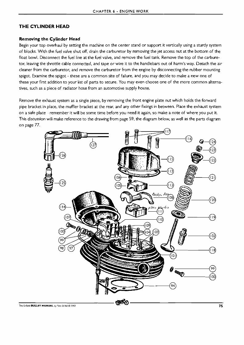
CHAPTER 6 - ENGINE WORK
THE CYLINDER HEAD
Removing the Cylinder Head Begin your top overhaul by setting the machine on the center stand or support it vertically using a sturdy system
of blocks. With the fuel valve shut off, drain the carburetor by removing the jet access nut at the bottom of the float bowl. Disconnect the fuel line at the fuel valve, and remove the fuel tank. Remove the top of the carbure-
tor, leaving the throttle cable connected, and tape or wire it to the handlebars out of harm's way. Detach the air cleaner from the carburetor, and remove the carburetor from the engine by disconnecting the rubber mounting
spigot. Examine the spigot - these are a common site of failure, and you may decide to make a new one of
these your first addition to your list of parts to secure. You may even choose one of the more common alterna- tives, such as a piece of radiator hose from an automotive supply house.
Remove the exhaust system as a single piece, by removing the front engine plate nut which holds the forward pipe bracket in place, the muffler bracket at the rear, and any other fixings in between. Place the exhaust system
on a safe place - remember it will be some time before you need it again, so make a note of where you put it.
This discussion will make reference to the drawing from page 59, the diagram below, as well as the parts diagram
on page 77.
The Enfield BULLET MANUAL by Pete hidal O 2002 75
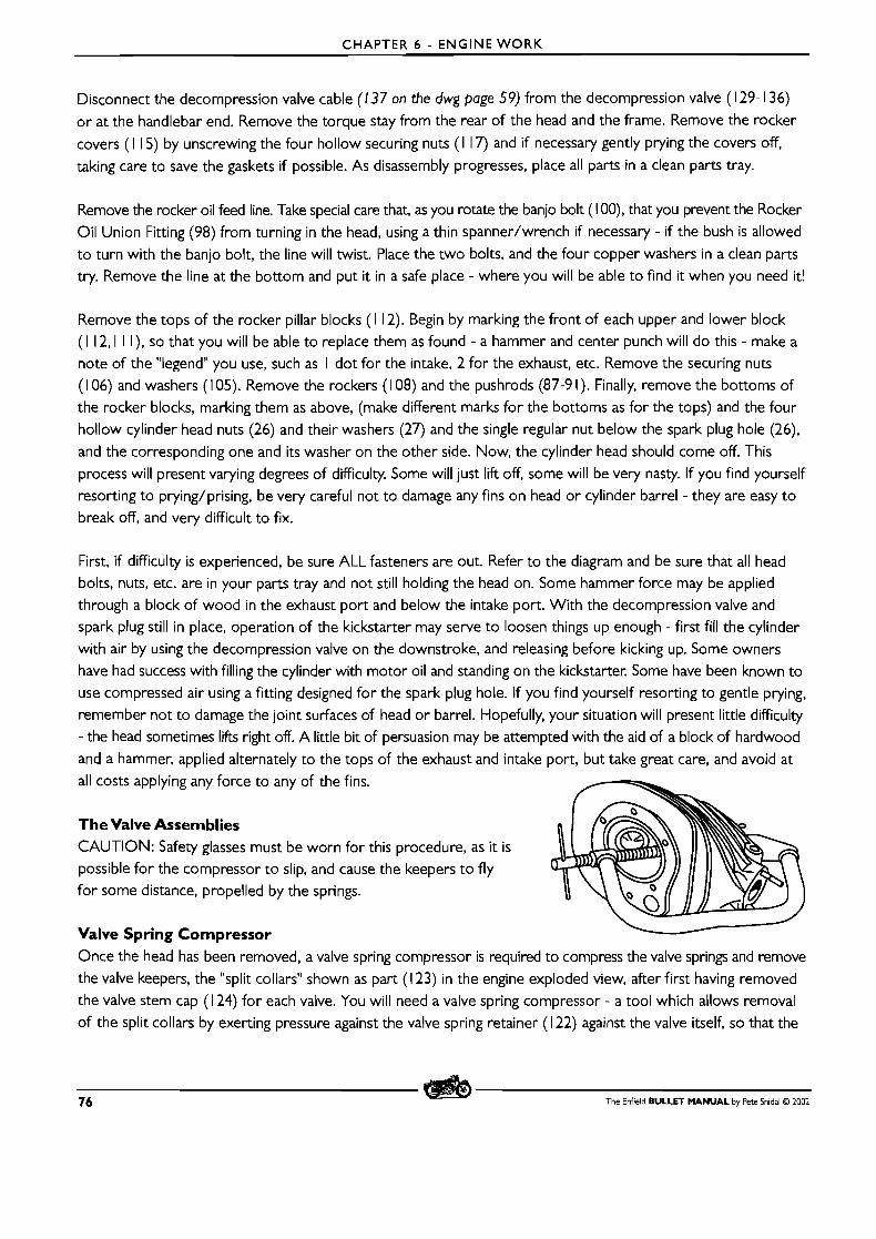
CHAPTER 6 - ENGINE WORK
Disconnect the decompression valve cable (137 on the dwg page 59) from the decompression valve (1 29- 136)
o r at the handlebar end. Remove the torque stay from the rear of the head and the frame. Remove the rocker
covers (1 15) by unscrewing the four hollow securing nuts (1 17) and if necessary gently prying the covers off,
taking care to save the gaskets if possible. As disassembly progresses, place all parts in a clean parts tray.
Remove the rocker oil feed line. Take special care that, as you rotate the banjo bolt ( 1 OO), that you prevent the Rocker
Oil Union Fitting (98) from turning in the head, using a thin spanner/wrench if necessary - if the bush is allowed
to turn with the banjo bolt, the line will twist. Place the two bolts, and the four copper washers in a clean parts
try. Remove the line at the bottom and put it in a safe place - where you will be able to find i t when you need it!
Remove the tops of the rocker pillar blocks ( 1 12). Begin by marking the front of each upper and lower block (1 12,l I I), so that you will be able to replace them as found - a hammer and center punch will do this - make a
note of the "legend" you use, such as I dot for the intake, 2 for the exhaust, etc. Remove the securing nuts (1 06) and washers ( 1 05). Remove the rockers ( 1 08) and the pushrods (87-9 I). Finally, remove the bottoms of
the rocker blocks, marking them as above, (make different marks for the bottoms as for the tops) and the four
hollow cylinder head nuts (26) and their washers (27) and the single regular nut below the spark plug hole (26),
and the corresponding one and its washer on the other side. Now, the cylinder head should come off. This
process will present varying degrees of difficulty. Some will just lift off, some will be very nasty. If you find yourself
resorting to prying/prising, be very careful not to damage any fins on head or cylinder barrel - they are easy to
break off, and very difficult to fix.
First, if difficulty is experienced, be sure ALL fasteners are out. Refer to the diagram and be sure that all head bolts, nuts, etc. are in your parts tray and not still holding the head on. Some hammer force may be applied
through a block of wood in the exhaust port and below the intake port. With the decompression valve and spark plug still in place, operation of the kickstarter may serve to loosen things up enough - first fill the cylinder
with air by using the decompression valve on the downstroke, and releasing before kicking up. Some owners
have had success with filling the cylinder with motor oil and standing on the kickstarter. Some have been known to
use compressed air using a fitting designed for the spark plug hole. If you find yourself resorting to gentle prying,
remember not to damage the joint surfaces of head or barrel. Hopefully, your situation will present little difficulty
- the head sometimes lifts right off. A little bit of persuasion may be attempted with the aid of a block of hardwood
and a hammer, applied alternately to the tops of the exhaust and intake port, but take great care, and avoid at all costs applying any force to any of the fins.
The Valve Assemblies CAUTION: Safety glasses must be worn for this procedure, as it is possible for the compressor to slip, and cause the keepers to fly
for some distance, propelled by the springs.
Valve Spring Compressor - Once the head has been removed, a valve spring compressor is required to compress the valve springs and remove
the valve keepers, the "split collars" shown as part ( 1 23) in the engine exploded view, after first having removed
the valve stem cap (1 24) for each valve. You will need a valve spring compressor - a tool which allows removal
of the split collars by exerting pressure against the valve spring retainer ( 1 22) against the valve itself, so that the
76 The Enfield BULLET MANUAL by Pete Snidal 63 2002
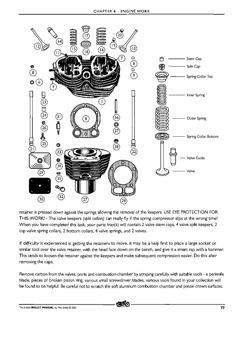
CHAPTER 6 - ENGINE WORK
8 Stem Cap
Split Cap
Spring Collar Top
Inner Spring
Outer Spring
Spring Collar Bottom
fl
0- Valve
retainer is pressed down against the springs allowing the removal of the keepers. USE M E PROTECTION FOR
THIS WORK! - The valve keepers (split collars) can really fly if the spring compressor slips at the wrong time!
When you have completed this task, your parts tray(s) will contain 2 valve stem caps, 4 valve split keepers, 2 top valve spring collars, 2 bottom collars, 4 valve springs, and 2 valves.
If difficulty is experienced in getting the retainers to move, it may be a help first to place a large socket or
similar tool over the valve retainer, with the head face down on the bench, and give it a smart rap with a hammer.
This tends to loosen the retainer against the keepers and make subsequent compression easier. Do this after removing the caps.
Remove carbon from the valves, ports and combustion chamber by scraping carefully with suitable tools - a penknife blade, pieces of broken piston ring, various small screwdriver blades, various tools found in your collection will be found to be helpful. Be careful not to scratch the soft aluminum combustion chamber and piston crown surfaces.
The Enfield BULLET MANUAL by Pete Snidal O 2CO2 77
CHAPTER 6 - ENGINE W O R K
The valves can be cleaned in a drill press, or even hand electric drill, by spinning them and holding emery cloth
against them - avoid inhaling the carbon dust given off in this process using a dust mask or similar precaution -
outside, in a strong wind, upwind is good. D O NOT, under any circumstances, use caustic soda or potash for
the removal of carbon from aluminium alloy - it will remove more than just the carbon!. Also, be sure to clean
the spark plug and decompressor valve threads carefully before reassembly - a wire brush is good for this, for
internal threads use one sold for battery terminal cleaning.
Examining thevalves, Guides, and Springs Valve wear is of two possibilities: wear on the perimeter of the valve faces, - the "margins," and wear of the guide
surfaces - the stems of the valves themselves. The margins - the flat face around the perimeter perpendicular to the faces, should be a minimum of I / 16"/.0625"/ 1.5mm after any necessary grinding has taken place. The
clearances between the stems and the valve guides (part 102 in the engine exploded dwg) may be checked by
attempting radial movement of the heads when they are just off their seats in the cylinder head. Max play should
be no more than just perceptible movement - more than this indicates a need for replacement of the guides, and possibly the valves as well. (nb: exhaust valve guide-to-stem clearance should be greater than the intake, to allow
for heat expansion of the valve - .002"/.05mm.)
Valve Stem Diameter Ranges: Inlet Valve Stem Diameter .3425"-.3430" .856-.857mm
Exhaust Valve Stem Diameter .3405"-.34 10" .85 1 -.852mm
If the valve stems measure up, but excessive clearance is detected, only the valve guides will have to be replaced.
Refacing the Valves and Seats The fit of the valves and seats may be checked with valve lapping compound and a lapping tool. Once the head and
valves are cleaned up, apply a little fine lapping compound to the valve seat, insert the valve, and rotate it in the
seat with the lapping tool for 30 seconds or so, moving it around occasionally as you spin the valve back and forth. This should produce a flat "sanded" area on both valve and seat a from I / 16" to I /8"/3mm wide. If the area is cupped, or not wide enough, check to see that the valve has not receded into the pocket formed by the valve seat - if this is the case, the valve, or the replaceable seat in the head must be replaced. If not, the valve and seat may
be refaced at a suitable automotive machine shop. Do not attempt to reface the valves and seats by "grinding"
with lapping compound and the lapping tool - this treatment is suitable only for checking the fit of the valve to
the seat. Refacing of the seat must be done with a refacing grinder, using a properly faced stone running on a
suitable guide pilot, and the valve itself must be refaced in a valve grinding lathe, o r refacing machine.
Choosing a Machine Shop Be careful not to entrust your valve work, or any motorcycle machine work, to a machine shop which does not
have the proper respect for motorcycle engines - some automotive shops consider all small engines to be in the
same category, from simple lawnmower units to high-performance motorcycle engines, and can be counted on
to do really shoddy work. On the contrary, motorcycle engines are in many cases more tricky than auto engines,
and require the services of a really knowledgeable specialist in small but powerful air-cooled engines. I t is very worthwhile to take the extra time to find a shop which takes motorcycle work seriously.
78 The Enfield BULLET MANUAL by Pete Snidal O 2002
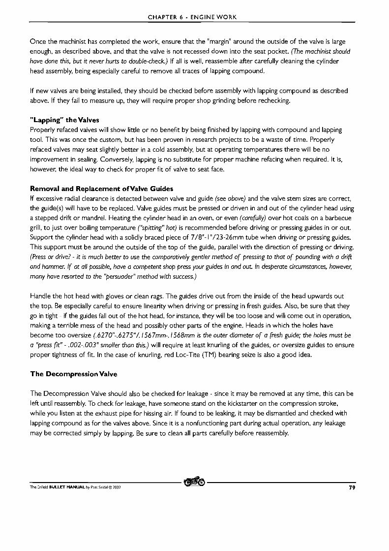
CHAPTER 6 - ENGINE W O R K
Once the machinist has completed the work, ensure that the "margin" around the outside of the valve is large
enough, as described above, and that the valve is not recessed down into the seat pocket. (The machinist should
have done this, but it never hurts to double-check.) If all is well, reassemble after carefully cleaning the cylinder
head assembly, being especially careful to remove all traces of lapping compound.
If new valves are being installed, they should be checked before assembly with lapping compound as described
above. If they fail to measure up, they will require proper shop grinding before rechecking.
"Lapping" the Valves Properly refaced valves will show little or no benefit by being finished by lapping with compound and lapping
tool. This was once the custom, but has been proven in research projects to be a waste of time. Properly
refaced valves may seat slightly better in a cold assembly, but at operating temperatures there will be no
improvement in sealing. Conversely, lapping is no substitute for proper machine refacing when required. It is,
however, the ideal way to check for proper fit of valve to seat face.
Removal and Replacement ofvalve Guides If excessive radial clearance is detected between valve and guide (see above) and the valve stem sizes are correct, the guide(s) will have to be replaced. Valve guides must be pressed or driven in and out of the cylinder head using
a stepped drift or mandrel. Heating the cylinder head in an oven, or even (carefully) over hot coals on a barbecue
grill, t o just over boiling temperature ("spitting" hot) is recommended before driving or pressing guides in or out.
Support the cylinder head with a solidly braced piece of 7/8"- 1 "/23-26mm tube when driving or pressing guides.
This support must be around the outside of the top of the guide, parallel with the direction of pressing or driving.
(Press or drive? - it is much better to use the comparatively gentler method of pressing to that of pounding with a drif?
and hammer. If at all possible, have a competent shop press your guides in and out. In desperate circumstances, however,
many have resorted to the "persuader" method with success.)
Handle the hot head with gloves or clean rags. The guides drive out from the inside of the head upwards out
the top. Be especially careful to ensure linearity when driving or pressing in fresh guides. Also, be sure that they
go in tight - if the guides fall out of the hot head, for instance, they will be too loose and will come out in operation, making a terrible mess of the head and possibly other parts of the engine. Heads in which the holes have
become too oversize (.6270"-.6275"/. 1567mm-. I568mm is the outer diameter of a fresh guide; the holes must be
a "press fit" - .002-.003" smaller than this.) will require at least knurling of the guides, or oversize guides to ensure
proper tightness of fit. In the case of knurling, red Loc-Tite (TM) bearing seize is also a good idea.
The Decompression Valve
The Decompression Valve should also be checked for leakage - since it may be removed at any time, this can be
left until reassembly. To check for leakage, have someone stand on the kickstarter on the compression stroke,
while you listen at the exhaust pipe for hissing air. If found to be leaking, it may be dismantled and checked with
lapping compound as for the valves above. Since it is a nonfunctioning part during actual operation, any leakage
may be corrected simply by lapping. Be sure to clean all parts carefully before reassembly.
The Enfield BULLET MANUAL by Pete Snidal O 2002 79
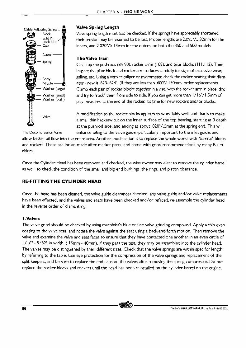
CHAPTER 6 - ENGINE W O R K
Valve Spring Length Valve spring length must also be checked. If the springs have appreciably shortened,
their tension may be assumed to be lost. Proper lengths are 2.095"/5.32mm for the
inners, and 2.020N/5. 13mm for the outers, on both the 350 and 500 models.
The Valve Train Clean up the pushrods (85-90), rocker arms ( 1 08) and pillar blocks (I I I, l 12). Then
Inspect the pillar block and rocker arm surfaces carefully for signs of excessive wear,
galling, etc. Using a vernier caliper or micrometer, check the rocker bearing shaft diam- eter - new is .623-.624". (If they are less than .600/. 150mm, order replacements.
Clamp each pair of rocker blocks together in a vise, with the rocker arm in place, dry, - Washer (small) and try to "rock" them from side to side. If you can get more than I / 16"/ 1.5mm of - Washer (plain) play measured at the end of the rocker, it's time for new rockers and/or blocks.
A modification to the rocker blocks appears to work fairly well, and that is to make Valve
a small thin hacksaw cut on the inner surface of the top bearing, starting at 0 depth
at the pushrod side, and ending at about .020"/.5mm at the spring end. This will The Decompression Valve enhance oiling to the valve guide -particularly important to the inlet guide, and
allow better oil flow into the entire area. Another modification is to replace the whole works with "Samrat" blocks
and rockers. These are Indian-made after-market parts, and come with good recommendations by many Bullet riders.
Once the Cylinder Head has been removed and checked, the wise owner may elect to remove the cylinder barrel as well, to check the condition of the small and big-end bushings, the rings, and piston clearance.
RE-FITTING THE CYLINDER HEAD
Once the head has been cleaned, the valve guide clearances checked, any valve guide and/or valve replacements
have been effected, and the valves and seats have been checked and/or refaced, re-assemble the cylinder head in the reverse order of dismantling.
I .Valves The valve grind should be checked by using machinist's blue or fine valve grinding compound. Apply a thin even
coating to the valve seat, and rotate the valve against the seat using a back-and-forth motion. Then remove the valve and examine the valve and seat faces to ensure that they have contacted one another in an even circle of I / 16" - 5/32" in width. (. 15mm - 40mm). If they pass the test, they may be assembled into the cylinder head.
The valves may be distinguished by their different sizes. Check that the valve springs are within spec for length
by referring to the table. Use eye protection for the compression of the valve springs and replacement of the
split keepers, and be sure to replace the end caps on the valves after removing the spring compressor. D o not
replace the rocker blocks and rockers until the head has been reinstalled on the cylinder barrel on the engine.
80 The Enfield BULLET MANUAL by Pete Sn~dal O 2002
CHAPTER 6 - ENGINE WORK
If the decompressor valve has been disturbed, ensure that it too is sealing properly using the above method, and
reassemble according t o the diagram.
Once the head has been re-assembled, oil up a new gasket with clean engine oil - this is to ensure that the gasket
can move freely around between the surfaces as the head is torqued down - clean and apply a light film of oil to the top surface of the cylinder, and fit the gasket to the top of the cylinder barrel. Then do the same to the gasket
face of the head, and fit the head over the gasket. Ensure that there is no dirt inside the threads of the bolt-like
head nuts, (parts 26 in the dwg) and, using the factory washers (24), screw the nuts down in stages, beginning with
"just snug." Tighten them up crosswise, Left-Front/Right Rear/Left Rear/Right Front to ensure bedding the head
down on the gasket as evenly as possible. Tighten to final torque in at least 3 stages, finishing with about 25 ft-lb.
Torquing Bolts Without aTorque Wrench A torque wrench is a device which incorporates a spring steel arm as part of a socket driver t o measure the torque, or twisting motion, applied t o a nut or bolt. When you use one properly, you will always notice that the
fastener moves through three distinct stages: easy movement, a space where it can be felt to tighten, and then a
"stop" stage, where movement stops.
If you use excessive force to go past this one, you'll feel a fourth "stretch" stage, in which the fastener stretches, possibly even followed by a fifth "snap or strip" stage, in which the threads or the fastener itself let go. The recommended torque setting will be at the "stop" stage. If you use a torque wrench, be careful to note these stages, - they should be a more reliable indicator of what you're doing than simple reliance on the calibration of the tool. And the
logical conclusion is that, if the mechanic uses this knowledge, and develops the "feel," a torque wrench is not really necessary. For this reason, I use one at all times, except when I don't have one available, or can't get it into the place I need it, in which cases I rely on the "feel" developed in the times when I could use it. This little
explanation should put paid t o the never ending controversy over whether or not you need a torque wrench - strictly speaking, you don't, but only after you've developed the "feel" through experience.
Re-Torquing the Head Gasket Once the engine has gone through a few heating/cooling cycles, it is advisable to strip the top back down to
accessibility and retorque the headbolts once again.
2.The Valve Train Once the head has been installed, we may proceed with the valve train. m Loosen off the pushrod adjuster locknuts, so that adjustment will be easier when they are installed. m With the head on, insert the pushrods down the pushrod tubes, adjuster ends first, and fit them onto the
cam followers/tappets (9 1 ). W Fit the bottom rocker blocks ( I I I ) onto their studs (1 04) on the head. When refitting the bottom blocks,
ensure that they have holes in which t o match up with oil feed holes on the cylinder head. Do this for both
bottom blocks.
m Lubricate the rocker arms with a coating of clean engine oil, ensuring that the valve caps (1 24) are in place
The Enfield BULLET MANUAL by Pete Snidal O 2002 8 1
CHAPTER 6 - ENGINE WORK
and that the rocker arms are fitted into the tops of the pushrods and are contacting the valve caps.
M Fit the top blocks (1 12) in place, and, using a "criss-cross" pattern, snug down the four fixing nuts ( 1 06) in
each case, being sure to use the washers they came with.(105) M Once the top blocks are snug, do an initial setting of the pushrod adjusters. Bring the engine t o TDC (top
dead center) on the compression stroke - both tappets down. Adjust the tappet adjusters/pushrod adjusters/tappets until they are just a finger tight fit. Finger tighten the locknuts as well. Then check the operation
of the valve train by rotating the engine a few turns. Ensure that there is no tightness anywhere, and that the
tappets, pushrods, valves, and rocker arms move freely as the engine rotates. m Then torque down the rocker block nuts fully. Feeling carefully for how the movement goes, tighten each down
with a light constant pressure until the spanner/wrench stops moving, and with enough pressure so that a bit more results in no more movement - this should be the "stop" point, after which stud stretch or thread damage
will take place. These are small nuts and studs, so use a short wrench, and no more than 2 or three fingers to pull it tight. Do the four nuts on each block in stages and in a criss-cross pattern. Torque setting for these is
very low! - 1 12.0 in-Lb - 9.4 Ft-Lb - 1.30 Kg-M
M Once the blocks are tight, go back to setting the valves for your initial start-up. Get the engine back to TDC
on compression (a screwdriver or spoke carefully held vertically in the spark plug hole will tell you where this is - compression stroke is the one in which neither valve is being depressed) and set each pushrod so that it just turns freely, but there is no perceptible up-and-down play possible. Be especially careful not to let the adjuster screw (90) turn relative t o the pushrod as you tighten the locknut (89.)
M Using fresh gaskets, install the rocker box covers (1 15). Do not use gasket sealer, as you will be removing them to re-torque the head nuts after some running time. Fit the spark plug and the decompressor valve, and your new top end should be ready for break-in.
M Re-fit the fuel tank, the fuel line, the various cables, etc.
Running in Your New Top End Before you even start your newly-refurbished motorcycle, be sure to take this opportunity to check your ignition timing. The procedure is fully described in Chapter 3. Once this is done, check your oil level, draining the sump
and replacing the oil in the tank if necessary, and start it up.
If ring replacement was not required, there is little in the way of fresh surfaces to run in. If the rings were replaced,
but the bore was not adulterated with a hone/"deglazer," all that will be necessary if for the high spots on the rings to "arc" themselves t o the shape of the bore - cast iron being a fairly soft and easily workable material, this
will all be done in the 500 t o 800 miles/800 t o 1000km or so, but for that time, you want t o avoid high rpm and any riding that will result in overheating - sitting in traffic, for instance. Vary the load as much as possible as you
ride, and avoid use of more than 1 /2 throttle for the first 500 miles/800km.
If a fresh piston and rebore was done, as well as the appropriate honing t o final size, the wearing in should be
done more carefully, and for a longer period - l000 t o 1500 miles/ 1600 to 2400km. Change your oil at the
first 500 miles, then at 1000, and finally again at 1500 or 2000. When you change your oil, examine the
drained oil in a strong light for metallic particles - these are the sandings from your cylinder bore, piston, and
rings, and they should become less apparent in the drained oil with each change, until they're finally back to
normal. D O N O T use any friction-reducing oil additives until the break-in period has been completed - the
82 The Enfield BULLET MANUAL by Fete Snidal O 2002

CHAPTER 6 - ENGINE WORK
reason for this is obvious. The cylinder head should be re-torqued after the first 3 or 4 heating/cooling
cycles, and the valve adjustment should be checked at I hour, 3 hours, 5 hours, and every I0 hours thereafter.
Hopefully no adjustment will be required.
Re-Torquing and Re-setting Check your pushrod settings frequently during the first few hours of running. See Chapter 4 for instructions.
As the engine goes through its first few temperature cycles, your initial adjustments will go awry. For this reason,
you should remove the tank and rocker covers, and re-torque the cylinder head nuts once or twice in the first 5
or I0 hours of operation.
REMOVING THE CYLINDER BARREL
An Explanation of Clearances The reason for removal of the Cylinder Barrel is to examine the clearances between the various parts of the
engine. Thus this section would logically begin with an explanation of clearances.
PistonlCylinder Clearances In order for the piston to slide up and down in the cylinder properly, its outer diameter must be smaller than
that of the bore of the cylinder. (The piston, by the way, is actually oval-shaped, with the distance across the ffskirts" - front to back at the bottom - being the greatest.) If the difference, or space, called clearance, is too great, a
condition called "piston slap" will attain, and the piston will get noisier and wear more rapidly until it fails. If the
clearance is too small, the piston will overheat and expand until it gets too tight in the bore, often seizing at the
high temperatures developed. (In this case, allowing the engine to cool will often albw restarting, but the piston will have "galled" the cylinder walls, and the engine will have to be dismantled and properly put back together. It is not a good idea to continue to operate a machine which has seized and come unstuck after cooling down.) Typical cold
piston clearance is in the neighborhood of .004"/. 1 Omm when new, and maximum allowable wear would create
a clearance in the neighborhood of .O I ON/.25mm. Beyond this, piston replacement, or even reboring and fitting of an oversize piston is required.
Although there is a certain amount of sealing between the piston and the cylinder, there would not be nearly
enough to allow the engine to run without the additional sealing provided by the piston rings - these expand and
contract as the piston goes up and down, conforming to minute variations in cylinder diameter, as well as providing
for differences as temperatures change. The rings have a gap at their ends, starting at .O I5"/.4mm when new. As
the rings wear on their outside edges (the diameter), the gap (the circumference) increases by a factor of pi, or
22/7, and they must be replaced by the time the gap surpasses the .030"/.8mm range. (.039-. /mm is given by the factory as an absolute maximum for the larger-bore 500.)
Enlarged ring gaps create complications in two ways, as the rings seal against oil coming up from below the piston,
as well as sealing compression and combustion pressures from getting down from the top. If the hot combustion
gasses meet the oil, it is burnt, making carbon deposits. If such carbon deposits accumulate in the ring lands - the
grooves in the piston in which the rings live - ring action is inhibited, which results in more leakage, so that more burning accumulates more carbon. This spiral effect eventually makes sealing so poor that compression suffers
The Enfield BULLET MANUAL by Pete Snidal O 2002 83
CHAPTER 6 - ENGINE WORK
to the point at which the machine becomes very difficult to start, and crankcase blow-by (out the vent above the
front of the primary cover) increases radically.
Connecting Rod Clearances The connecting rod clearances need also to be examined. First, the wrist, or gudgeon pin clearance - does the
piston "rock" laterally on the rod? If so, there is too great a clearance in the small end of the rod, and the small-
end bush must be replaced. And finally, we check for end-play of the rod itself on the crankpin - any perceptible
play here means that the engine must be further dismantled, and the rod assembly must be replaced by a com-
petent shop - this job again requires special tools, and is beyond the scope of the home mechanic. The good
news for the latter two is that a rod assembly usually outlasts a number of top ends - pistons, rebores, valve jobs, etc., so in most cases the job stops at the cylinder gasket.
Removing the Cylinder Barrel Loosen the nuts on the horizontal studs on each side of the crankcase cylinder spigot at the base of the cylinder barrel, and remove the two nuts on the vertical studs which hold the cylinder on each side to the crankcase.
(One of these is inside the tappet chest.) Then, carefully pry up the cylinder base from the crankcase, using equal pressure all around the joint. It may be helpful to apply a little force from side to side and front t o back with a
block of wood and a small hammer - be careful not to damage the fins!
Once the joint has been broken, move the piston Top Dead Center by moving the rear wheel with machine in
gear, o r by rotating the alternator rotor nut with a spanner. Now, with the machine in I s t gear, to prevent the
engine from turning during cylinder removal, slide the cylinder barrel up until the piston skirt is just visible. This is
a good time t o wrap the connecting rod with a clean rag, so as to prevent the entrance of any broken ring
material into the crankcase. Finally, turn the engine over once again until the piston is at Bottom Dead Center,
and slide the barrel upwards off the piston. Once the barrel is removed, put it aside in a safe, clean, dry place. Carefully inspect the rag in the crankcase mouth for any bits of ring and/or piston which may have fallen away
during the removal, and clean them out if necessary.
Examination of Piston and Rings Now for the piston rings. Rotate the engine until the piston is at TDC (top dead center), Then carefully spread
the ends of the top ring with the thumbs - or with a special tool for the purpose, called of all things a "piston
ring expander," until the ring is expanded enough to slide over the top of the piston. Keep in mind that piston
rings are extremely brittle, and will break with little distortion from their original shape. It may be helpful to support the piston with a couple of short pieces of wood across the crankcase mouth - rotate the engine until the piston is pulled down snugly against the props.
Up and Down. Many piston rings have a top and a bottom, due to being vertically tapered on the outside face
for a scraper effect. Although the two surfaces are generally marked, with a "TOP or a circle on the top one,
it never hurts to place them in their tray in the same orientation as when they were removed, and in the same order. Keep them topside up as you do any further operations with them, just in case they will be reusable,
and/or look for any marks which indicate which way they must go.
84 The Enfield BULLET MANUAL by Pere Snidal O 2002
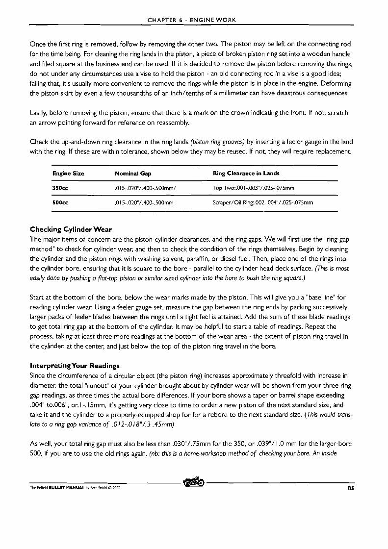
CHAPTER 6 - ENGINE W O R K
Once the f i rs t ring is removed, follow by removing the other two. The piston may be left on the connecting rod
for the time being. For cleaning the ring lands in the piston, a piece of broken piston ring set into a wooden handle
and filed square at the business end can be used. If it is decided to remove the piston before removing the rings, do not under any circumstances use a vise to hold the piston - an old connecting rod in a vise is a good idea;
failing that, it's usually more convenient to remove the rings while the piston is in place in the engine. Deforming the piston skirt by even a few thousandths of an inch/tenths of a millimeter can have disastrous consequences.
Lastly, before removing the piston, ensure that there is a mark on the crown indicating the front. If not, scratch
an arrow pointing forward for reference on reassembly.
Check the up-and-down ring clearance in the ring lands (piston ring grooves) by inserting a feeler gauge in the land with the ring. If these are within tolerance, shown below they may be reused. If not, they will require replacement.
Engine Size Nominal Gap Ring Clearance in Lands
3 5 0 ~ ~ .O 15-.020/.400-.500rnrn/ Top Two:.OO I -.003"/.025-,075mrn
500cc .O 15-.020/.400-.500mm Scraper/Oil Ring:.002-.004"/.025-.075mm
Checking Cylinder Wear The major items of concern are the piston-cylinder clearances, and the ring gaps. We will first use the "ring-gap
method" to check for cylinder wear, and then to check the condition of the rings themselves. Begin by cleaning the cylinder and the piston rings with washing solvent, paraffin, or diesel fuel. Then, place one of the rings into
the cylinder bore, ensuring that it is square to the bore - parallel to the cylinder head deck surface. (This is most easily done by pushing a flat-top piston or similar sized cylinder into the bore to push the ring square.)
Start at the bottom of the bore, below the wear marks made by the piston. This will give you a "base line" for reading cylinder wear. Using a feeler gauge set, measure the gap between the ring ends by packing successively
larger packs of feeler blades between the rings until a tight feel is attained. Add the sum of these blade readings to get total ring gap at the bottom of the cylinder. It may be helpful to start a table of readings. Repeat the process, taking at least three more readings at the bottom of the wear area - the extent of piston ring travel in
the cylinder, at the center, and just below the top of the piston ring travel in the bore.
InterpretingYour Readings Since the circumference of a circular object (the piston ring) increases approximately threefold with increase in
diameter, the total "runout" of your cylinder brought about by cylinder wear will be shown from your three ring
gap readings, as three times the actual bore differences. If your bore shows a taper or barrel shape exceeding .004" to.006", or. I -. 15mm, it's getting very close to time to order a new piston of the next standard size, and take it and the cylinder to a properly-equipped shop for for a rebore to the next standard size. (This would trans- late to a ring gap variance of .0 1 2-. 0 1 8"/.3-. 45mm)
As well, your total ring gap must also be less than .030/.75mm for the 350, or .039"/ I .O mm for the larger-bore 500, if you are to use the old rings again. (nb: this is a home-workshop method of checking your bore. An inside
The Enfield BULLET MANUAL by Pete Snidal O 2002 85
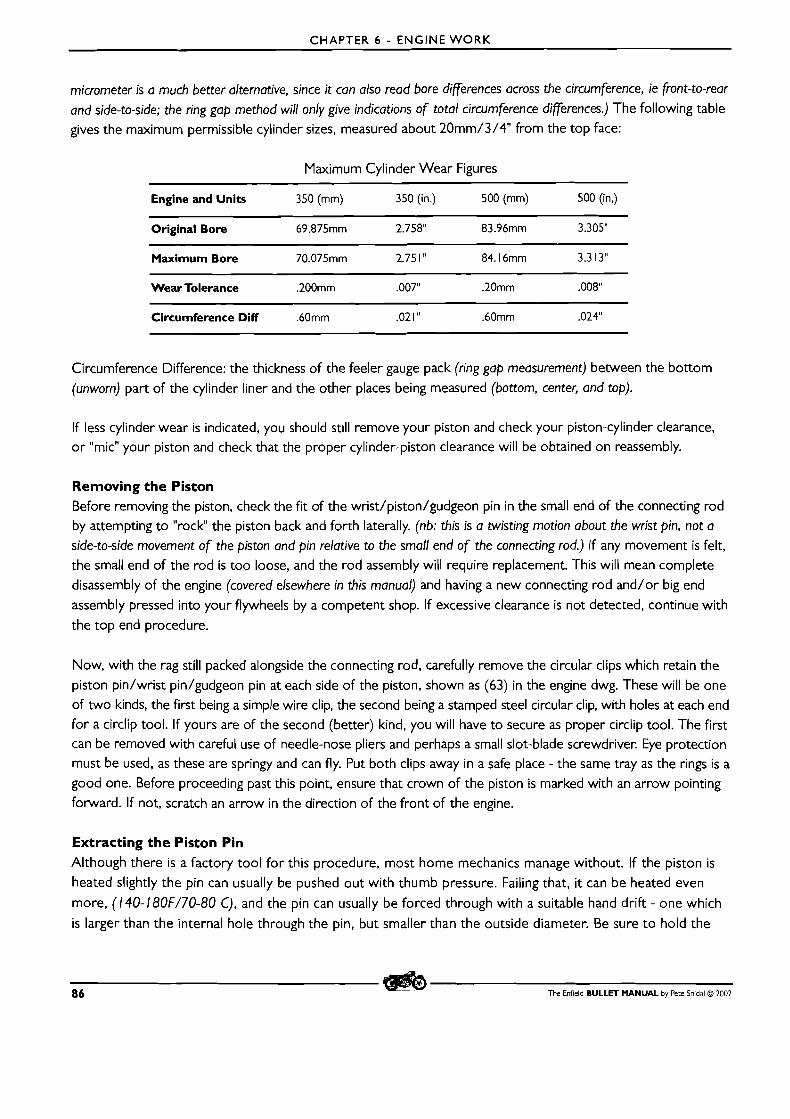
CHAPTER 6 - ENGINE WORK
micrometer is a much better alternative, since it can also read bore differences across the circumference, ie front-to-rear and side-to-side; the ring gap method will only give indications of total circumference differences.) The following table gives the maximum permissible cylinder sizes, measured about 20mm/3/411 from the top face:
Maximum Cylinder Wear Figures
Engine and Units 350 (mm) 350 (in.) 500 (mm) 500 (in,)
Original Bore 69.875mm 2.758" 83.96mm 3.305"
Maximum Bore 70.075mm 2.75 1 " 84.16mm 3.3 13"
Wear Tolerance .200mm .007" .20mm .000
Circumference Diff .60mm .02 1 " .60mm .024"
Circumference Difference: the thickness of the feeler gauge pack (ring gap measurement) between the bottom (unworn) part of the cylinder liner and the other places being measured (bottom, center, and top).
If less cylinder wear is indicated, you should still remove your piston and check your piston-cylinder clearance, o r "mic" your piston and check that the proper cylinder-piston clearance will be obtained on reassembly.
Removing the Piston Before removing the piston, check the fit of the wrist/piston/gudgeon pin in the small end of the connecting rod by attempting to "rock the piston back and forth laterally. (nb: this is a twisting motion about the wrist pin, not a side-to-side movement of the piston and pin relative to the small end of the connecting rod.) If any movement is felt, the small end of the rod is too loose, and the rod assembly will require replacement. This will mean complete disassembly of the engine (covered elsewhere in this manual) and having a new connecting rod and/or big end
assembly pressed into your flywheels by a competent shop. If excessive clearance is not detected, continue with
the top end procedure.
Now, with the rag still packed alongside the connecting rod, carefully remove the circular clips which retain the piston pin/wrist pin/gudgeon pin at each side of the piston, shown as (63) in the engine dwg. These will be one
of two kinds, the first being a simple wire clip, the second being a stamped steel circular clip, with holes at each end for a circlip tool. If yours are of the second (better) kind, you will have to secure as proper circlip tool. The first can be removed with careful use of needle-nose pliers and perhaps a small slot-blade screwdriver. Eye protection must be used, as these are springy and can fly. Put both clips away in a safe place - the same tray as the rings is a good one. Before proceeding past this point, ensure that crown of the piston is marked with an arrow pointing
forward. If not, scratch an arrow in the direction of the front of the engine.
Extracting the Piston Pin Although there is a factory tool for this procedure, most home mechanics manage without. If the piston is
heated slightly the pin can usually be pushed out with thumb pressure. Failing that, it can be heated even
more, (140-180F/70-80 C), and the pin can usually be forced through with a suitable hand drift - one which
is larger than the internal hole through the pin, but smaller than the outside diameter. Be sure t o hold the
86 The Enfield BULLET MANUAL by Pete Snidal O 2002
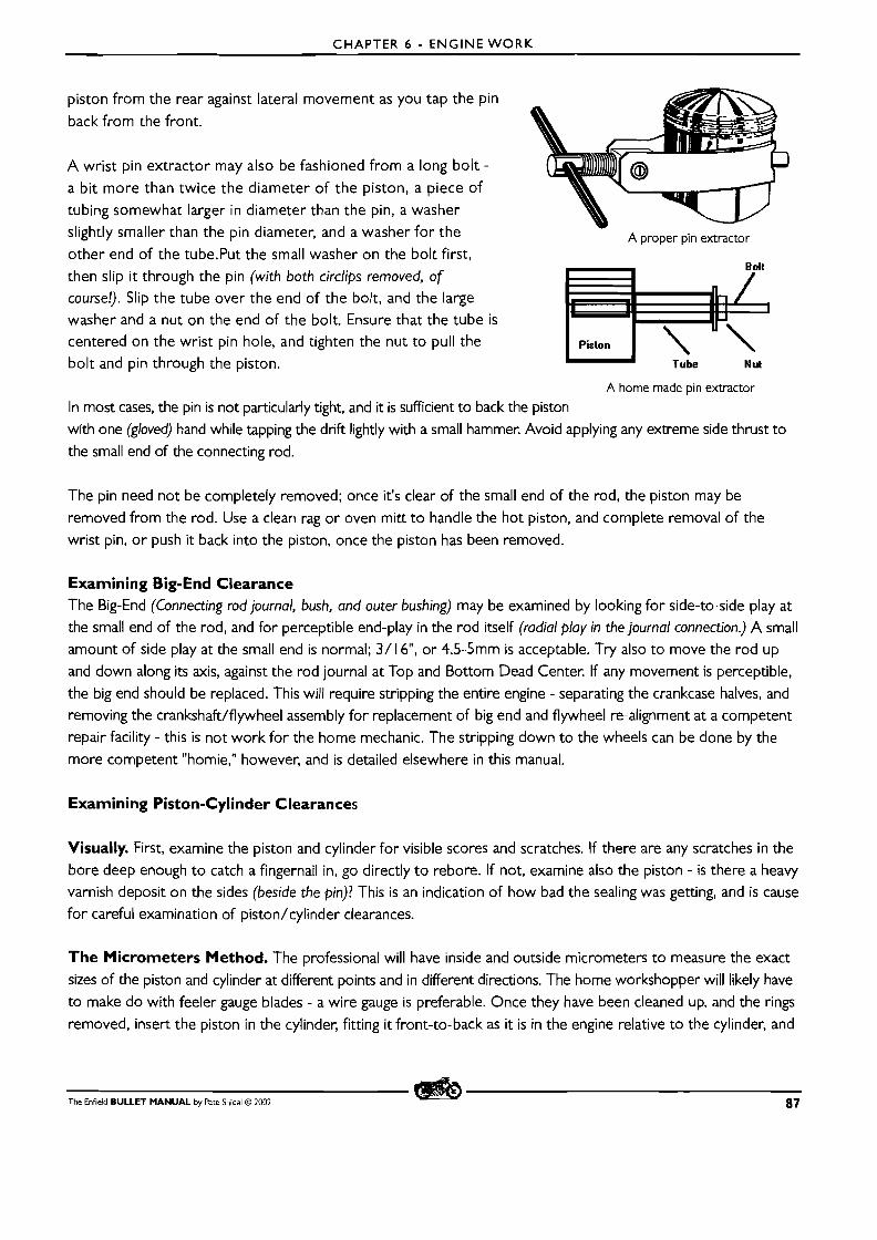
CHAPTER 6 - ENGINE WORK
piston from the rear against lateral movement as you tap the pin
back from the front.
A wrist pin extractor may also be fashioned from a long bolt -
a bit more than twice the diameter of the piston, a piece of tubing somewhat larger in diameter than the pin, a washer
slightly smaller than the pin diameter, and a washer for the A proper pin extractor other end of the tube.Put the small washer on the bolt first, then slip i t through the pin (with both circlips removed, of course!). Slip the tube over the end of the bolt, and the large washer and a nut on the end of the bolt. Ensure that the tube is
centered on the wrist pin hole, and tighten the nut to pull the I Piston I \ ' \ bolt and pin through the piston. ~ u b e NU^
A home made pin extractor
In most cases, the pin is not particularly tight, and it is sufficient to back the piston with one (gloved) hand while tapping the drift lightly with a small hammer. Avoid applying any extreme side thrust to
the small end of the connecting rod.
The pin need not be completely removed; once it's clear of the small end of the rod, the piston may be
removed from the rod. Use a clean rag or oven mitt t o handle the hot piston, and complete removal of the wrist pin, or push it back into the piston, once the piston has been removed.
Examining Big-End Clearance
The Big-End (Connecting rod journal, bush, and outer bushing) may be examined by looking for side-to-side play at the small end of the rod, and for perceptible end-play in the rod itself (radial play in the journal connection.) A small amount of side play at the small end is normal; 3/ 16", or 4.5-5mm is acceptable. Try also t o move the rod up
and down along its axis, against the rod journal at Top and Bottom Dead Center. If any movement is perceptible,
the big end should be replaced. This will require stripping the entire engine - separating the crankcase halves, and removing the crankshaft/flywheel assembly for replacement of big end and flywheel re-alignment at a competent repair facility - this is not work for the home mechanic. The stripping down to the wheels can be done by the
more competent "homie," however, and is detailed elsewhere in this manual.
Examining Piston-Cylinder Clearances
Visually. First, examine the piston and cylinder for visible scores and scratches. If there are any scratches in the
bore deep enough t o catch a fingernail in, go directly t o rebore. If not, examine also the piston - is there a heavy varnish deposit on the sides (beside the pin)? This is an indication of how bad the sealing was getting, and is cause for careful examination of piston/cylinder clearances.
T h e Micrometers Method. The professional will have inside and outside micrometers to measure the exact
sizes of the piston and cylinder at different points and in different directions. The home workshopper will likely have to make do with feeler gauge blades - a wire gauge is preferable. Once they have been cleaned up, and the rings
removed, insert the piston in the cylinder, fitting it front-to-back as it is in the engine relative to the cylinder, and
The Enfield BULLET MANUAL by Pete Snidal C2 2002 87
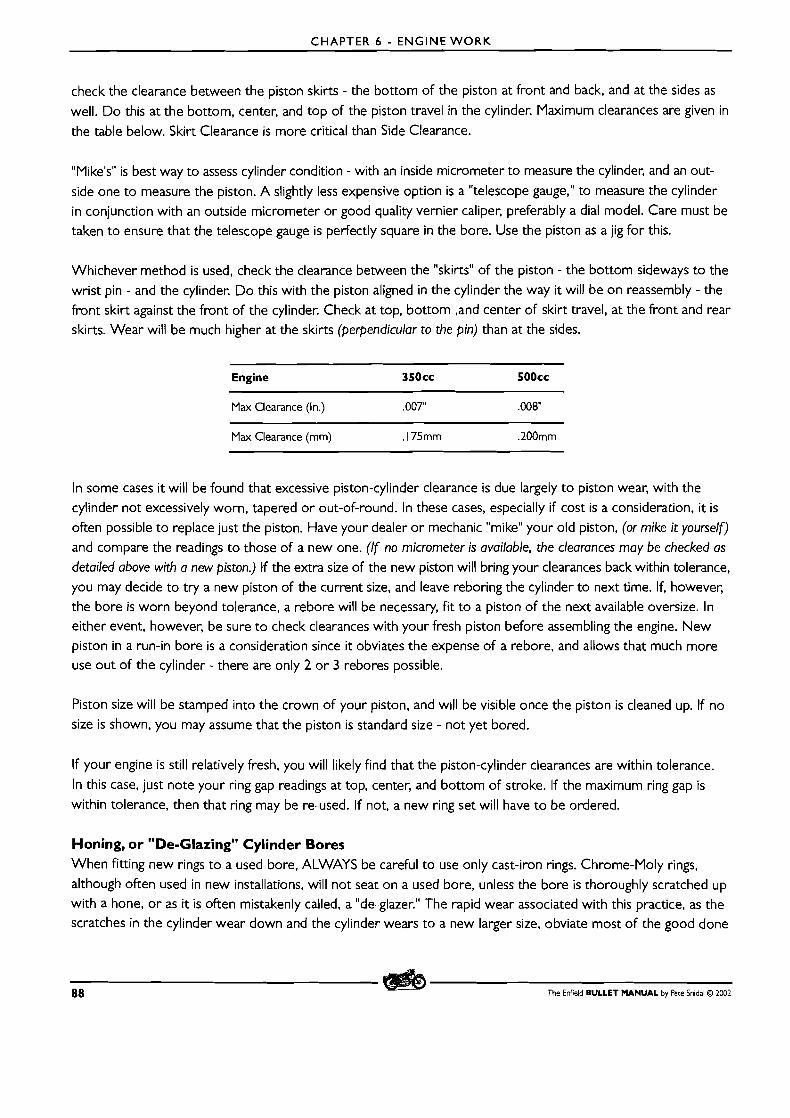
CHAPTER 6 - ENGINE WORK
check the clearance between the piston skirts - the bottom of the piston at front and back, and at the sides as
well. Do this at the bottom, center, and top of the piston travel in the cylinder. Maximum clearances are given in
the table below. Skirt Clearance is more critical than Side Clearance.
"Plike's" is best way to assess cylinder condition - with an inside micrometer to measure the cylinder, and an out- side one to measure the piston. A slightly less expensive option is a "telescope gauge," to measure the cylinder
in conjunction with an outside micrometer or good quality vernier caliper, preferably a dial model. Care must be taken to ensure that the telescope gauge is perfectly square in the bore. Use the piston as a jig for this.
Whichever method is used, check the clearance between the "skirts" of the piston - the bottom sideways to the wrist pin - and the cylinder. D o this with the piston aligned in the cylinder the way it will be on reassembly - the
front skirt against the front of the cylinder. Check at top, bottom ,and center of skirt travel, at the front and rear skirts. Wear will be much higher at the skirts (perpendicular to the pin) than at the sides.
Engine 3 5 0 ~ ~ 500cc
Max Clearance (In.) ,007" .008
Max Clearance (mm) . I75mm .200mm
In some cases i t will be found that excessive piston-cylinder clearance is due largely t o piston wear, with the
cylinder not excessively worn, tapered or out-of-round. In these cases, especially if cost is a consideration, it is often possible to replace just the piston. Have your dealer or mechanic "mike" your old piston, (or mike it yourself) and compare the readings t o those of a new one. (If no micrometer is available, the clearances may be checked as
detailed above with a new piston.) If the extra size of the new piston will bring your clearances back within tolerance, you may decide to try a new piston of the current size, and leave reboring the cylinder to next time. If, however, the bore is worn beyond tolerance, a rebore will be necessary, fit to a piston of the next available oversize. In either event, however, be sure to check clearances with your fresh piston before assembling the engine. New piston in a run-in bore is a consideration since it obviates the expense of a rebore, and allows that much more use out of the cylinder - there are only 2 or 3 rebores possible.
Piston size will be stamped into the crown of your piston, and will be visible once the piston is cleaned up. If no size is shown, you may assume that the piston is standard size - not yet bored.
If your engine is still relatively fresh, you will likely find that the piston-cylinder clearances are within tolerance.
In this case, just note your ring gap readings at top, center, and bottom of stroke. If the maximum ring gap is
within tolerance, then that ring may be re-used. If not, a new ring set will have t o be ordered.
Honing, or "De-Glazing" Cylinder Bores When fitting new rings t o a used bore, ALWAYS be careful to use only cast-iron rings. Chrome-Moly rings,
although often used in new installations, will not seat on a used bore, unless the bore is thoroughly scratched up with a hone, or as it is often mistakenly called, a "de-glazer." The rapid wear associated with this practice, as the scratches in the cylinder wear down and the cylinder wears to a new larger size, obviate most of the good done
88 The Enfield BULLET MANUAL by Pete Snidal O 2002
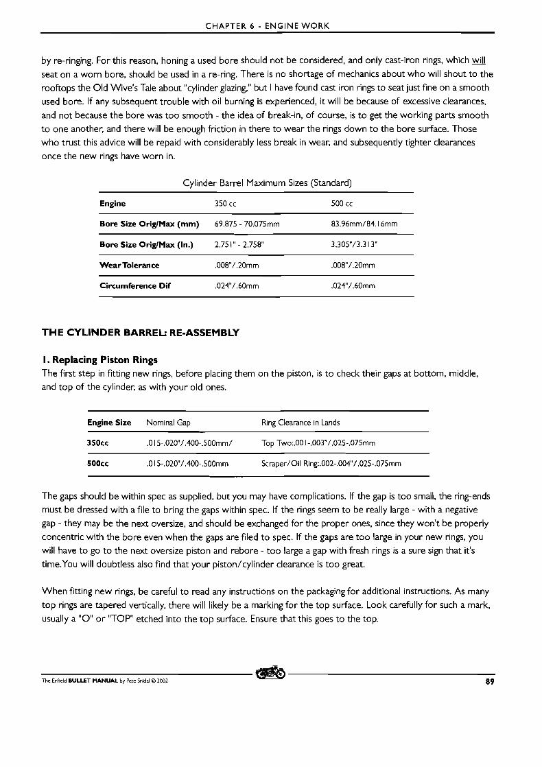
CHAPTER 6 - ENGINE W O R K
by re-ringing. For this reason, honing a used bore should not be considered, and only cast-iron rings, which
seat on a worn bore, should be used in a re-ring. There is no shortage of mechanics about who will shout to the
rooftops the Old Wive's Tale about "cylinder glazing," but I have found cast iron rings to seat just fine on a smooth
used bore. If any subsequent trouble with oil burning is experienced, it will be because of excessive clearances,
and not because the bore was too smooth - the idea of break-in, of course, is to get the working parts smooth
to one another, and there will be enough friction in there to wear the rings down to the bore surface. Those
who trust this advice will be repaid with considerably less break in wear, and subsequently tighter clearances
once the new rings have worn in.
Cylinder Barrel Maximum Sizes (Standard)
Engine 350 cc 500 cc
Bore Size OriglMax (mm) 69.875 - 70.075mm 83.96mm/84.16mm
Bore Size OriglMax (In.) 2.75 l " - 2.758" 3.3OSv/3.3 13"
Wear Tolerance .008"/.20mm .008"/.20mm
Circumference Dif .024"/.60mm .024"/.60mm
T H E CYI-INDER BARREL: RE-ASSEMBLY
I. Replacing Piston Rings The first step in fitting new rings, before placing them on the piston, is t o check their gaps at bottom, middle, and top of the cylinder, as with your old ones.
Engine Size Nominal Gap Ring Clearance in Lands
350cc .O I 5-.020"/.400-.500mm/ Top Two:.OO I -.003"/.025-.075mm
The gaps should be within spec as supplied, but you may have complications. If the gap is too small, the ring-ends
must be dressed with a file to bring the gaps within spec. If the rings seem to be really large - with a negative
gap - they may be the next oversize, and should be exchanged for the proper ones, since they won't be properly
concentric with the bore even when the gaps are filed to spec. If the gaps are too large in your new rings, you
will have to go to the next oversize piston and rebore - too large a gap with fresh rings is a sure sign that it's
time.You will doubtless also find that your piston/cylinder clearance is too great.
When fitting new rings, be careful to read any instructions on the packaging for additional instructions. As many
top rings are tapered vertically, there will likely be a marking for the top surface. Look carefully for such a mark,
usually a " 0 " o r "TOP etched into the top surface. Ensure that this goes to the top.
The Enfield BULLET MANUAL by Pete Snidal O 2002 89
CHAPTER 6 - ENGINE WORK
To fit the rings on the piston, first support it in the crankcase cylinder spigot by bunching clean rag around it.
Then, beginning with the oil, or scraper ring, (this may be in more than one piece), and using a ring spreading
tool or the thumbs of both hands, carefully spread the ring over the top of the piston, keeping in mind at all
times the brittleness of piston ring material, and ease it over the piston crown and down to its slot. Follow up with the middle ring, and finally the top one. Align the ring gaps at 120 degrees to one another to ensure best
sealing on startup.
2. Fitting the Piston Apply some light grease to the small end bush in the connecting rod.
m Heat the Piston if necessary, and push the wrist pin out one side until it protrudes very slightly into the center. m Lock the wristpin circlip into its slot in the side opposite the protruding wristpin.
m Ensure that it is a tight fit in its groove. If a "wire" type, you may need to stretch it before reinstallation.
m With the engine at Top Dead Center, put the piston onto the rod, being careful to place the "front" arrow
to the front - you will have to wiggle the protruding wristpin into the rod small end. m Then press the wristpin through the rod bushing and the other side of the piston until it butts against the circlip.
m Stuff the crankcase mouth under the piston with a clean rag, so as not to chance losing the second circlip in the crankcase, and lock in the second circlip. (Important hint: It is good at this point to make a note, in writing, that you have both circlips in place - saves much possible soul-searching after you have the whole engine reassembled. Don't ask9
3.The Cylinder Barrel Use a new base gasket, and gasket sealer such as Permatex Ill Aviation, or silicone form-a-gasket (caution: use silicone very sparingly, paying particular attention to avoiding letting enough get on the inside of the gasket fact to become squeezed into the engine on assembly - this stuff will play havoc with filter screens and pump parts!) CopperkoteTM gasket sealer is
also very good - it allows re-use of most gaskets. Use of "shellac-type" gasket sealers is not recommended - they
make subsequent dismantling difficult, and any re-use of gaskets impossible. Properly applied, CopperkoteTM, or
PermatexTM silicone or aviation gasket sealer (Ill) are completely satisfactory in this application. Apply the gasket to
the crankcase cylinder spigot, and a thin film of gasket sealer to the top of the gasket. Pay particular attention to the
area around the base of the tappet chest - all your hot return oil runs through these two holes.
m Support the piston over the crankcase mouth with two pieces of clean splinterless wood straddling the mouth,
alongside the rod, from front to rear. Rotate the engine until the piston is solidly against the wood pieces. m Apply a generous coating of engine oil to the piston rings. Then arrange the gaps in a 120 degree pattern so
that they aren't lined up. m Now introduce the cylinder to the top of the piston. Hold it at the point at which it just passes over the piston
crown - before it contacts the first piston ring. Support it at this elevation with the sides of the index fingers of both hands.
m Press the top ring into its slot at the rear of the piston, (relative to you), "smoothing" it around with the index fingers,
and using your thumbnails at the front to hold the gap closed. - you want the ring gap to be completely closed.
m Now lower the cylinder barrel over (just) the closed end of the first ring, holding it in with the fingertips until
the barrel lip pushes them down off the ring. At this point, the barrel is slightly tilted away from you - toward
the closed end. Lower it over the closed end first, and then rock it towards the open end, with your thumb
nails still holding the gap closed. Do not allow the cylinder to contact the second ring.
m Repeat the process for the second and third rings.
90 The Enfield B U L L E T M A N U A L by Pete Snidal O ZOO2
CHAPTER 6 - ENGINE WORK
This is not a simple procedure for the novice, and it is very important that none of the brittle cast-iron rings is
broken. I t is sometimes a help to have a second pair of hands in the process, sometimes not. The beginner may
want to do a practice run with the old rings f i rs t t o develop a technique. There may be temptations to use some sort of ring compressor, but a standard automotive one is not satisfactory, as it's made t o pull off the top of the
piston after it's lowered into the cylinder. If a ring compressor designed t o be removed from around the rod is available, by all means use it, but jury-rigged designs using old strips of sheet metal and hoseclamps, etc. are seldom satisfactory. The time-honoured method is the one described above. Be especially careful t o listen for the tell-tale
"snap" of a ring as the cylinder is lowered. If you think you hear it, pull the cylinder off and check your work. Cylinders have been known t o be installed (after a time) with one old ring.
Once the cylinder has been placed over the piston, seat it fully on the crankcase, and fit the small nut on the
stud in the pushrod chamber. Take care not t o overtighten this small-diameter nut - when the gasket sealer
begins to squeeze out of the outside of the joint, it's tight enough. Be sure to use a lock washer. Cover the top
of the cylinder with a clean rag until you refit the cylinder head.
SPLITTING THE CRANKCASE
The last step in complete engine tear-down, or to service to the main or big end bearings.
Before proceeding any further, examine the big end once more for end-play. Grip the small end of the rod firmly and attempt t o move i t up and down at top and bottom dead centers, and at the two mid points. Check also for side-play at these points. Any perceptible end-play, or more than I /4"-6mm of side play is cause for dismantling the
big-end for examination and replacement of floating center bush, and/or crankpin and/or steel outer rod bushing.
The engine, of course, must be removed from the frame, and the gearbox removed from the rear of the engine. If either is still in place, remove the cylinder head and cylinder barrel. The primary drive side must be completely
disassembled, and the inner primary case and gearbox removed from crankcase.
Timing Chest Before it will be possible t o draw the timing-side case half over the timing-side crankpin, the timing pinion will
have t o be removed. This means removing the timing cover, and the timing gears and other innards as follows:
Contact Breaker and Drive Gear While the timing gears are still meshed, remove the nut retaining the contact breaker drive gear, and remove the gear. If difficulty is experienced holding the cb gear from turning, a small block of soft wood between two of the timing gears will help, or the timing pinion may be replaced loosely on the crankpin. Unbolt the contact breaker unit and
put it and the gear and nut aside. Make a note to order a new oil seal - this wear part should be replaced on reassembly.
Remove each of the timing gears, with its spacing washer on each side, and place in a clean parts tray. Do the same
with the camwheels, and the cam followers. Follow the instructions to remove the crankshaft timing pinion.
Then remove the nuts from either end of each crankcase stud and push each stud through the crankcase.
Place all studs, nuts, and washers in the parts tray. The cases will now be ready for separation.
The Enfield BULLET MANUAL by Pece Snidal O 2002 9 1
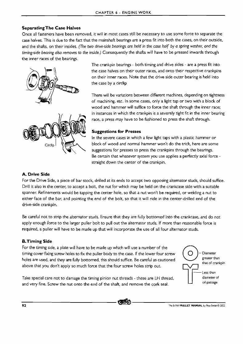
CHAPTER 6 - ENGINE W O R K
Separating The Case Halves Once all fasteners have been removed, it will in most cases still be necessary t o use some force t o separate the
case halves. This is due t o the fact that the mainshaft bearings are a press fit into both the cases, on their outside,
and the shafts, on their insides. (The two drive-side bearings are held in the case half by a spring washer, and the
timing-side bearing also removes to the inside.) Consequently the shafts will have to be pressed inwards through the inner races of the bearings.
'The crankpin bearings - both timing and drive sides - are a press fit into
the case halves on their outer races, and onto their respective crankpins on their inner races. l l o te that the drive side outer bearing is held into
the case by a circlip
There will be variations between different machines, depending on tightness of machining, etc. In some cases, only a light tap or two with a block of wood and hammer will suffice t o force the shaft through the inner race; in instances in which the crankpin is a severely tight fit in the inner bearing race, a press may have t o be fashioned to press the shaft through.
Suggestions for Presses In the severe cases in which a few light taps with a plastic hammer o r
block of wood and normal hammer won't do the trick, here are some
suggestions for presses t o press the crankpins through the bearings.
Be certain that whatever system you use applies a perfectly axial force - straight down the center of the crankpin.
A. Drive Side For the Drive Side, a piece of bar stock, drilled at its ends t o accept two opposing alternator studs, should suffice. Drill it also in the center, t o accept a bolt, the nut for which may be held on the crankcase side with a suitable spanner. Refinements would be tapping the center hole, so that a nut won't be required, or welding a nut t o either face of the bar, and pointing the end of the bolt, so that it will ride in the center-drilled end of the drive-side crankpin.
Be careful not to strip the alternator studs. Ensure that they are fully bottomed into the crankcase, and do not
apply enough force t o the larger puller bolt to pull out the alternator studs. If more than reasonable force is
required, a puller will have to be made up that will incorporate the use of all four alternator studs.
&Timing Side For the timing side, a plate will have to be made up which will use a number of the timing cover fixing screw holes to fix the puller body to the case. If the lower four screw Diameter
holes are used, and they are fully bottomed, this should suffice. Be careful as cautioned greater than that of crankpin
above that you don't apply so much force that the four screw holes strip out.
Less than
Take special care not t o damage the timing pinion nut threads - these are LH thread, diameter of
and very fine. Screw the nut onto the end of the shaft, and remove the cork seal. oil passage
9 2 The Enfield BULLET MANUAL by Pete Snidal O 2002
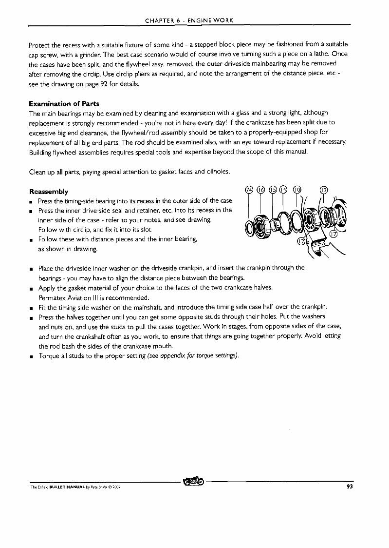
CHAPTER 6 - ENGINE WORK
Protect the recess with a suitable fixture of some kind - a stepped block piece may be fashioned from a suitable
cap screw, with a grinder. The best case scenario would of course involve turning such a piece on a lathe. Once the cases have been split, and the flywheel assy. removed, the outer driveside mainbearing may be removed after removing the circlip. Use circlip pliers as required, and note the arrangement of the distance piece, etc -
see the drawing on page 92 for details.
Examination of Parts The main bearings may be examined by cleaning and examination with a glass and a strong light, although
replacement is strongly recommended - you're not in here every day! If the crankcase has been split due to
excessive big end clearance, the flywheel/rod assembly should be taken t o a properly-equipped shop for replacement of all big end parts. The rod should be examined also, with an eye toward replacement if necessary.
Building flywheel assemblies requires special tools and expertise beyond the scope of this manual.
Clean up all parts, paying special attention t o gasket faces and oilholes.
Reassembly m Press the timing-side bearing into its recess in the outer side of the case. m Press the inner drive-side seal and retainer, etc. into i ts recess in the
inner side of the case - refer to your notes, and see drawing. Follow with circlip, and fix it into its slot
m Follow these with distance pieces and the inner bearing,
as shown in drawing.
m Place the driveside inner washer on the driveside crankpin, and insert the crankpin through the
bearings - you may have to align the distance piece between the bearings.
M Apply the gasket material of your choice t o the faces of the two crankcase halves.
Permatex Aviation Ill is recommended. m Fit the timing side washer on the mainshaft, and introduce the timing side case half over the crankpin.
m Press the halves together until you can get some opposite studs through their holes. Put the washers
and nuts on, and use the studs to pull the cases together. Work in stages, from opposite sides of the case,
and turn the crankshaft often as you work, to ensure that things are going together properly. Avoid letting the rod bash the sides of the crankcase mouth.
M Torque all studs to the proper setting (see appendix for torque settings).
The Enfield BULLET MANUAL by Pete Snidal 0 l002 93
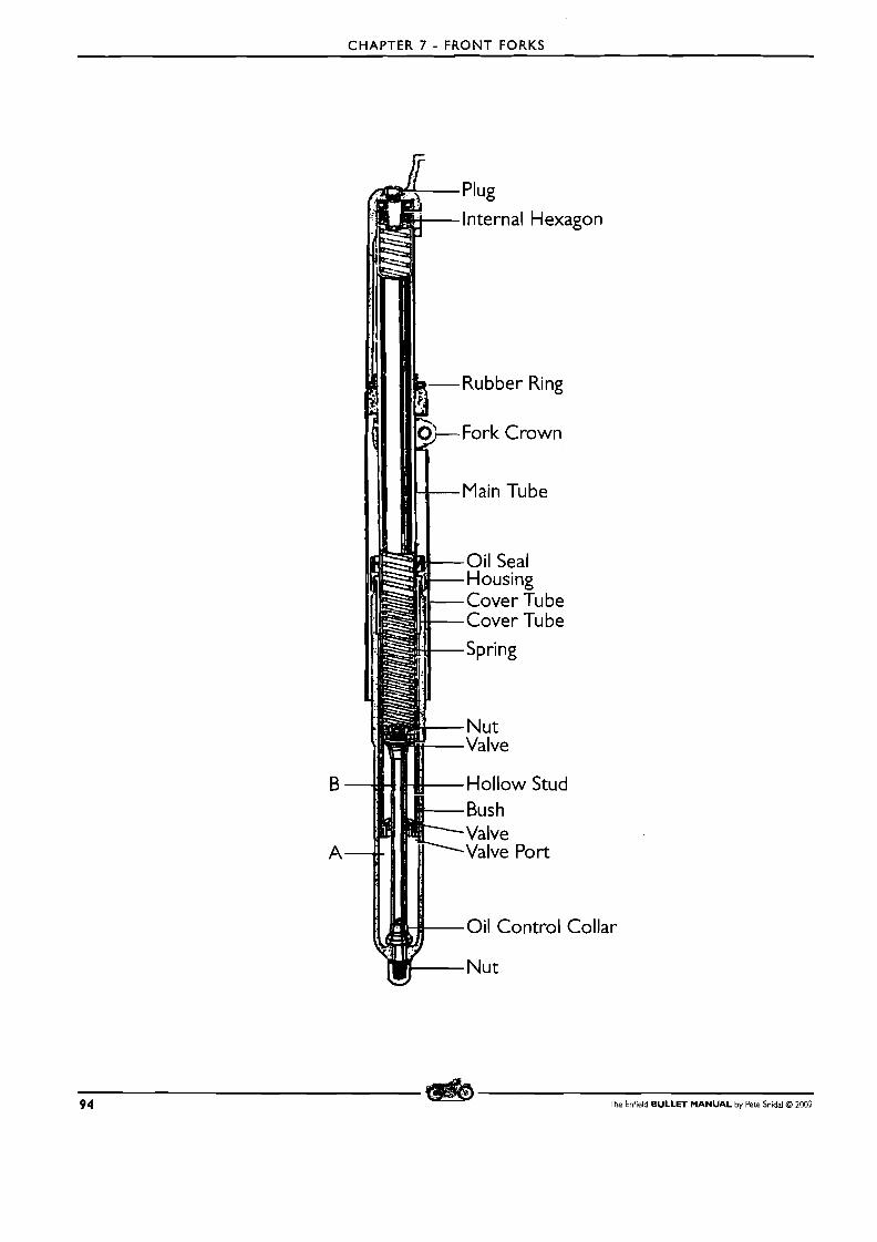
CHAPTER 7 - FRONT FORKS
Oil Control Collar
94 The Enfield BULLET MANUAL by Pere Snidal O 2002
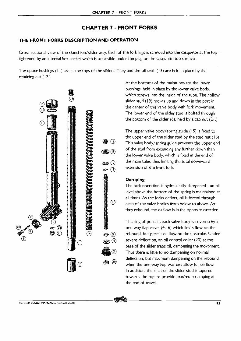
CHAPTER 7 - FRONT FORKS
CHAPTER 7 - FRONT FORKS
THE FRONT FORKS DESCRIPTION A N D OPERATION
Cross-sectional view of the stanchion/slider assy. Each of the fork legs is screwed into the casquette at the top -
tightened by an internal hex socket which is accessible under the plug on the casquette top surface.
The upper bushings ( I I ) retaining nut ( l 2.)
are at the tops of t l i e sliders. They and the oil seals ( 1 3) are held in place by the
A t the bottoms of the maintubes are the lower bushings, held in place by the lower valve body,
which screws into the inside of the tube. The hollow
slider stud ( I 9) moves up and down in the port in the center of this valve body with fork movement.
The lower end of the slider stud is bolted through the bottom of the slider (6), held by a cap nut (2 1 .)
The upper valve body/spring guide ( 15) is fixed t o the upper end of the slider stud by the stud nut (1 6)
@ This valve body/spring guide prevents the upper end
m@ of the stud from extending any further down than
the lower valve body, which is fixed in the end of
B the main tube, thus limiting the total downward
extension of the front fork.
Damping The fork operation is hydraulically dampened - an oil level above the bottom of the spring is maintained at
all times. As the forks deflect, oil is forced through @ each of the valve bodies from below t o above. As
they rebound, the oil flow is in the opposite direction.
The ring of ports in each valve body is covered by a one-way flap valve, (4,16) which limits flow on the
@ rebound, but permit oil flow on the upstroke. Under
@ severe deflection, an oil control collar (20) at the -
base of the slider traps oil, dampening the movement.
40 Thus there is little to no dampening on normal
deflection, but maximum dampening on the rebound, m @ when the one-way flap washers allow full oil flow.
In addition, the shaft of the slider stud is tapered towards the top, to provide maximum damping at
the end of travel.
The Enfield BULLET MANUAL by Pete Snidal O 2002 95
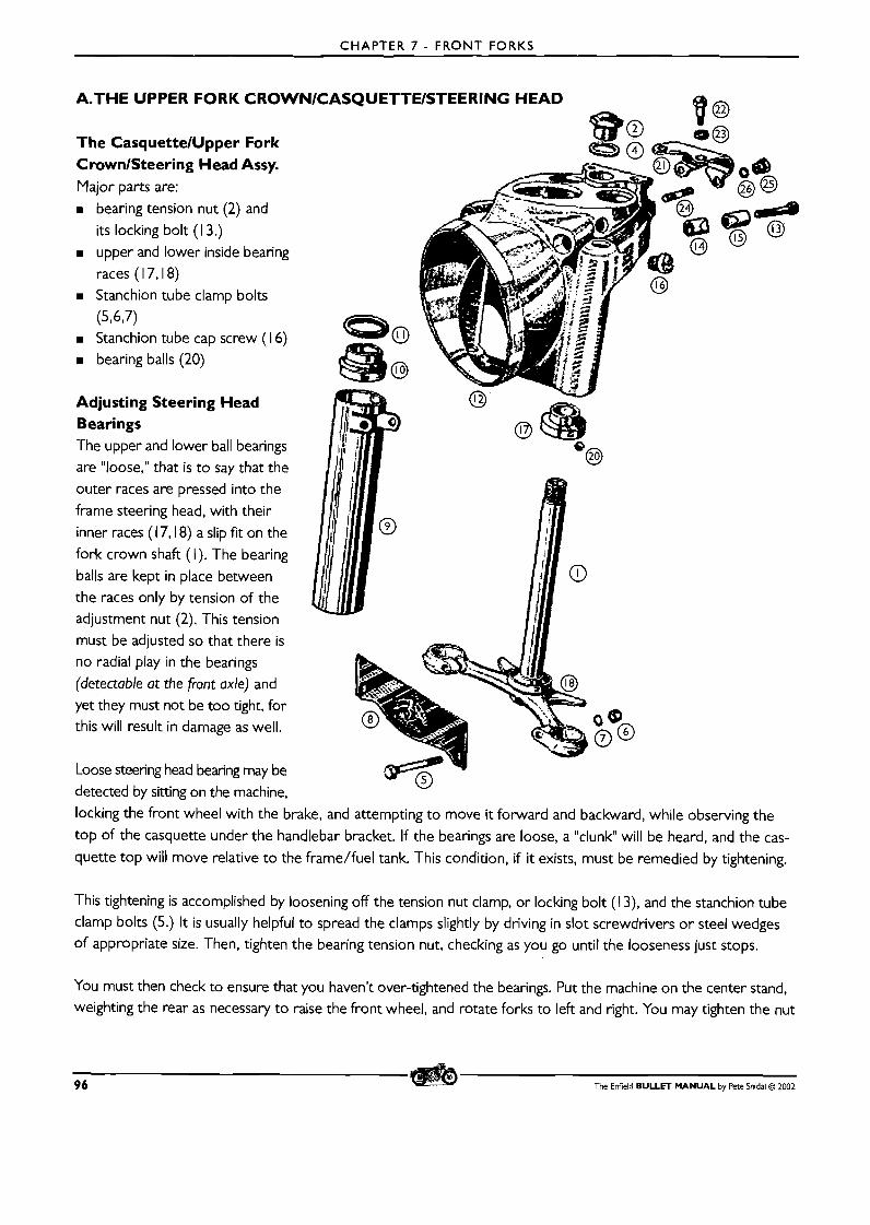
CHAPTER 7 - FRONT FORKS
detected by sitting on the machine, locking the front wheel with the brake, and attempting t o move it forward and backward, while observing the top of the casquette under the handlebar bracket. If the bearings are loose, a "clunk" will be heard, and the cas-
quette top will move relative t o the frame/fuel tank. This condition, if it exists, must be remedied by tightening.
This tightening is accomplished by loosening off the tension nut clamp, or locking bolt (1 3), and the stanchion tube clamp bolts (5.) It is usually helpful to spread the clamps slightly by driving in slot screwdrivers or steel wedges of appropriate size. Then, tighten the bearing tension nut, checking as you go until the looseness just stops.
You must then check to ensure that you haven't over-tightened the bearings. Put the machine on the center stand, weighting the rear as necessary t o raise the front wheel, and rotate forks to left and right. You may tighten the nut
96 The Enfield BULLET MANUAL by Pete Snidal 0 ZOO2
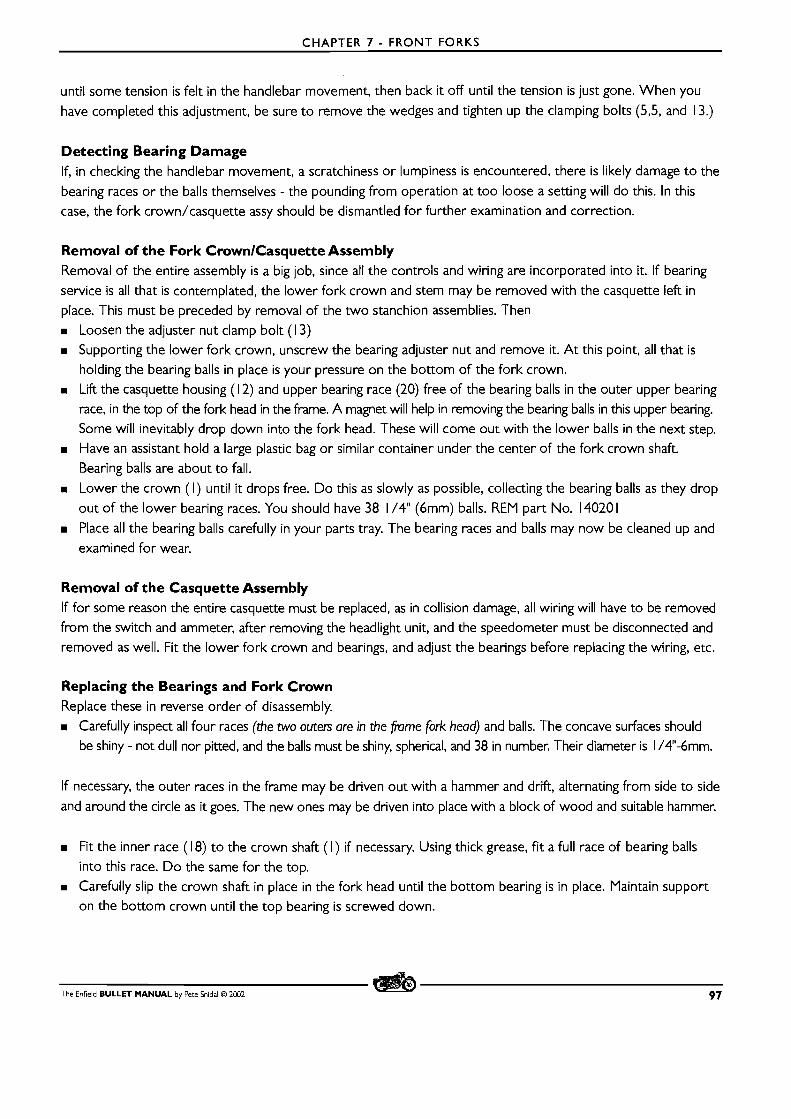
CHAPTER 7 - FRONT FORKS
until some tension is felt in the handlebar movement, then back it off until the tension is just gone. When you
have completed this adjustment, be sure to remove the wedges and tighten up the clamping bolts (5,5, and 13.)
Detecting Bearing Damage If, in checking the handlebar movement, a scratchiness o r lumpiness is encountered, there is likely damage to the
bearing races or the balls themselves - the pounding from operation at too loose a setting will do this. In this case, the fork crown/casquette assy should be dismantled for further examination and correction.
Removal of the Fork CrownlCasquette Assembly Removal of the entire assembly is a big job, since all the controls and wiring are incorporated into it. If bearing
service is all that is contemplated, the lower fork crown and stem may be removed with the casquette left in
place. This must be preceded by removal of the two stanchion assemblies. Then
m Loosen the adjuster nut clamp bolt ( l 3) m Supporting the lower fork crown, unscrew the bearing adjuster nut and remove it. A t this point, all that is
holding the bearing balls in place is your pressure on the bottom of the fork crown. m Lift the casquette housing (1 2) and upper bearing race (20) free of the bearing balls in the outer upper bearing
race, in the top of the fork head in the frame. A magnet will help in removing the bearing balls in this upper bearing.
Some will inevitably drop down into the fork head. These will come out with the lower balls in the next step. m Have an assistant hold a large plastic bag or similar container under the center of the fork crown shaft.
Bearing balls are about to fall.
m Lower the crown ( I ) until it drops free. Do this as slowly as possible, collecting the bearing balls as they drop
out of the lower bearing races. You should have 38 1 /4" (6mm) balls. REM part No. 14020 1 m Place all the bearing balls carefully in your parts tray. The bearing races and balls may now be cleaned up and
examined for wear.
Removal of the Casquette Assembly If for some reason the entire casquette must be replaced, as in collision damage, all wiring will have to be removed
from the switch and ammeter, after removing the headlight unit, and the speedometer must be disconnected and removed as well. Fit the lower fork crown and bearings, and adjust the bearings before replacing the wiring, etc.
Replacing the Bearings and Fork Crown Replace these in reverse order of disassembly.
m Carefully inspect all four races (the two outers are in the frame fork head) and balls. The concave surfaces should
be shiny - not dull nor pitted, and the balls must be shiny, spherical, and 38 in number. Their diameter is I /4"-6mm.
If necessary, the outer races in the frame may be driven out with a hammer and drift, alternating from side to side
and around the circle as it goes. The new ones may be driven into place with a block of wood and suitable hammer.
m Fit the inner race (1 8) to the crown shaft ( I ) if necessary. Using thick grease, fit a full race of bearing balls
into this race. D o the same for the top.
m Carefully slip the crown shaft in place in the fork head until the bottom bearing is in place. Maintain support
on the bottom crown until the top bearing is screwed down.
The Enfield BULLET MANUAL by Pete Snidal O 2002 97
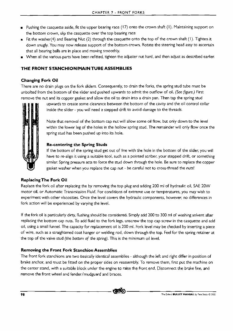
CHAPTER 7 - FRONT FORKS
m Pushing the casquette aside, fit the upper bearing race (1 7) onto the crown shaft (I). Maintaining support on
the bottom crown, slip the casquette over the top bearing race
Fit the washer(4) and Bearing Nut (2) through the casquette onto the top of the crown shaft (I). Tighten it
down snugly. You may now release support of the bottom crown. Rotate the steering head assy to ascertain that all bearing balls are in place and moving smoothly. When all the various parts have been refitted, tighten the adjuster nut hard, and then adjust as described earlier.
THE FRONT STANCHlONlMAlN TUBE ASSEMBLIES
Changin There arc
unbolted
remove t
g Fork Oil no drain plugs on the fork sliders. Consequently, to drain the forks, the spring stud tube must be
rom the bottom of the slider and pushed upwards to admit the outflow of oil. (See figure.) First
le nut and its copper gasket and allow the oil t o drain into a drain pan. Then tap the spring stud upwards to create some clearance between the bottom of the cavity and the oil control collar
inside the slider - you will need a stepped drift to avoid damage to the threads.
Note that removal of the bottom cap nut will allow some oil flow, but only down t o the level
within the lower leg of the holes in the hollow spring stud. The remainder will only flow once the
spring stud has been pushed up into its hole.
Re-centering the Spring Studs If the bottom of the spring stud get out of line with the hole in the bottom of the slider, you will have to re-align it using a suitable tool, such as a pointed scriber, your stepped drift, or something
similar. Spring pressure acts to force the stud down through the hole. Be sure t o replace the copper
gasket washer when you replace the cap nut - be careful not to cross-thread the nuts!
ReplacingThe Fork Oil Replace the fork oil after replacing the by removing the top plug and adding 200 ml of hydraulic oil, SAE 20W motor oil, o r Automatic Transmission Fluid. For conditions of extreme use o r temperatures, you may wish t o experiment with other viscosities. Once the level covers the hydraulic components, however, no differences in fork action will be experienced by varying the level.
If the fork oil is particularly dirty, flushing should be considered. Simply add 200 to 300 ml of washing solvent after replacing the bottom cap nuts. To add fluid to the fork legs, unscrew the top cap screw in the casquette and add oil, using a small funnel. The capacity for replacement oil is 200 ml. Fork level may be checked by inserting a piece
of wire, such as a straightened coat hanger o r welding rod, down through the top. Feel for the spring retainer at
the top of the valve stud (the bottom of the spring). This is the minimum oil level.
Removing the Front Fork Stanchion Assemblies The front fork stanchions are two basically identical assemblies - although the left and right differ in position of
brake anchor, and must be fitted on the proper sides on reassembly. To remove them, first put the machine on
the center stand, with a suitable block under the engine to raise the front end. Disconnect the brake line, and
remove the front wheel and fender/mudguard and braces.
98 The Enfield BULLET MANUAL by Pete Snidal O 2002
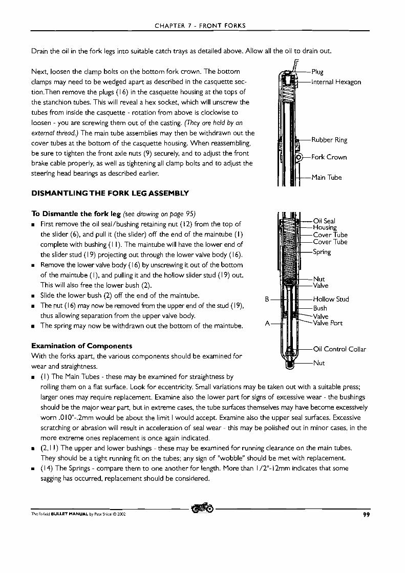
CHAPTER 7 - FRONT FORKS
Drain the oil in the fork legs into suitable catch trays as detailed above. Allow all the oil to drain out.
Next, loosen the clamp bolts on the bottom fork crown. The bottom Plug clamps may need t o be wedged apart as described in the casquette sec- Internal Hexagon
tion.Then remove the plugs (1 6) in the casquette housing at the tops of the stanchion tubes. This will reveal a hex socket, which will unscrew the
tubes from inside the casquette - rotation from above is clockwise t o
loosen - you are screwing them out of the casting. (They are held by an
external thread.) The main tube assemblies may then be withdrawn out the cover tubes at the bottom of the casquette housing. When reassembling, Rubber Ring
be sure to tighten the front axle nuts (9) securely, and t o adjust the front Fork Crown brake cable properly, as well as tightening all clamp bolts and to adjust the steering head bearings as described earlier. ( (1 [ I f ~ a i n Tube
DISMANTLING THE FORK LEG ASSEMBLY
To Dismantle the fork leg (see drawing on page 95) W First remove the oil seal/bushing retaining nut ( l 2) from the top of
the slider (6), and pull it (the slider) off the end of the maintube ( I ) complete with bushing ( I I). The maintube will have the lower end of
the slider stud ( 19) projecting out through the lower valve body (1 6). W Remove the lower valve body ( 1 6) by unscrewing it out of the bottom
of the maintube (I), and pulling it and the hollow slider stud (1 9) out. This will also free the lower bush (2).
U Slide the lower bush (2) off the end of the maintube. The nut (1 6) may now be removed from the upper end of the stud ( I 9), thus allowing separation from the upper valve body.
W The spring may now be withdrawn out the bottom of the maintube.
Examination of Components With the forks apart, the various components should be examined for wear and straightness.
Oil Seal Housing Cover Tube Cover Tube Spring
lVut Valve
B Hollow Stud Bush Valve
A Valve Port
Oil Control Collar
Nut
U ( I ) The Main Tubes - these may be examined for straightness by
rolling them on a flat surface. Look for eccentricity. Small variations may be taken out with a suitable press;
larger ones may require replacement. Examine also the lower part for signs of excessive wear - the bushings
should be the major wear part, but in extreme cases, the tube surfaces themselves may have become excessively worn .O 10"-.2mm would be about the limit I would accept. Examine also the upper seal surfaces. Excessive
scratching or abrasion will result in acceleration of seal wear - this may be polished out in minor cases, in the more extreme ones replacement is once again indicated.
U (2,l I ) The upper and lower bushings - these may be examined for running clearance on the main tubes.
They should be a tight running fit on the tubes; any sign of "wobble" should be met with replacement. m ( 1 4) The Springs - compare them to one another for length. More than 1 /2"- 12mm indicates that some
sagging has occurred, replacement should be considered.
The Enfield BULLET MANUAL by Pete Snidal O 2002 99
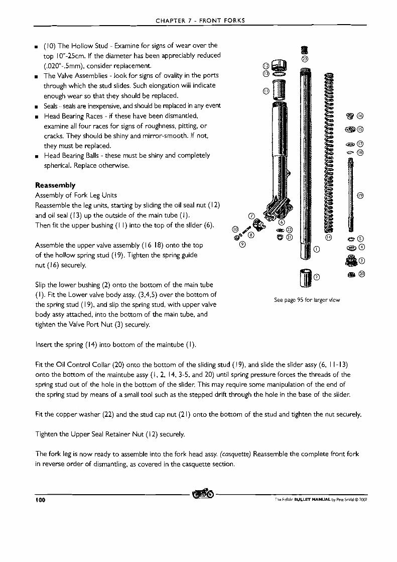
CHAPTER 7 - FRONT FORKS
M (1 0) The Hollow Stud - Examine for signs of wear over the
top 10"-25cm. If the diameter has been appreciably reduced (.020N-.5mm), consider replacement.
M The Valve Assemblies - look for signs of ovality in the ports
through which the stud slides. Such elongation will indicate
enough wear so that they should be replaced.
m Seals - seals are inexpensive, and should be replaced in any event
M Head Bearing Races - if these have been dismantled, examine all four races for signs of roughness, pitting, or cracks. They should be shiny and mirror-smooth. If not, they must be replaced. Head Bearing Balls - these must be shiny and completely spherical. Replace otherwise.
Reassembly Assembly of Fork Leg Units
Reassemble the leg units, starting by sliding the oil seal nut (1 2)
and oil seal ( 1 3) up the outside of the main tube (I). Then fit the upper bushing ( I I ) into the top of the slider (6).
Assemble the upper valve assembly ( 1 6- 18) onto the top
of the hollow spring stud ( I 9). Tighten the spring guide nut ( l 6) securely.
Slip the lower bushing (2) onto the bottom of the main tube (I). Fit the Lower valve body assy. (3,4,5) over the bottom of the spring stud ( I 9), and slip the spring stud, with upper valve
See page 95 for larger view
body assy attached, into the bottom of the main tube, and
tighten the Valve Port Nut (3) securely.
Insert the spring (14) into bottom of the maintube (I).
Fit the Oil Control Collar (20) onto the bottom of the sliding stud ( l 9), and slide the slider assy (6, 1 I - 13) onto the bottom of the maintube assy (1, 2, 14, 3-5, and 20) until spring pressure forces the threads of the spring stud out of the hole in the bottom of the slider. This may require some manipulation of the end of
the spring stud by means of a small tool such as the stepped drift through the hole in the base of the slider.
Fit the copper washer (22) and the stud cap nut (2 1) onto the bottom of the stud and tighten the nut securely.
Tighten the Upper Seal Retainer Nut (1 2) securely.
The fork leg is now ready t o assemble into the fork head assy. (casquette) Reassemble the complete front fork in reverse order of dismantling, as covered in the casquette section.
100 The Enfield BULLET MANUAL by Pete Snidal O 2002
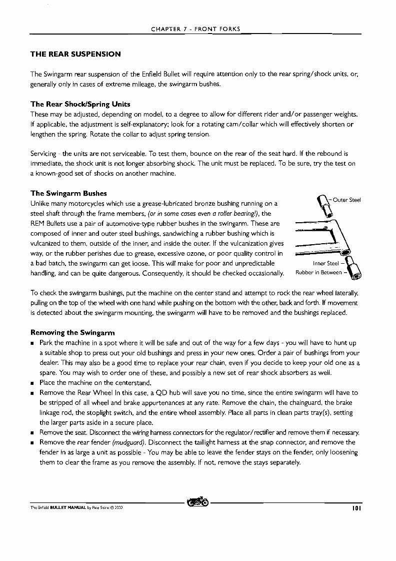
CHAPTER 7 - FRONT FORKS
'THE REAR SUSPENSION
The Swingarm rear suspension of the Enfield Bullet will require attention only to the rear spring/shock units, or,
generally only in cases of extreme mileage, the swingarm bushes.
The Rear ShocklSpring Units These may be adjusted, depending on model, to a degree to allow for different rider and/or passenger weights.
If applicable, the adjustment is self-explanatory; look for a rotating cam/collar which will effectively shorten o r
lengthen the spring. Rotate the collar to adjust spring tension.
Servicing - the units are not serviceable. To test them, bounce on the rear of the seat hard. If the rebound is immediate, the shock unit is not longer absorbing shock. The unit must be replaced. To be sure, try the test on a known-good set of shocks on another machine.
The Swingarm Bushes - Outer Steel Unlike many motorcycles which use a grease-lubricated bronze bushing running on a
steel shaft through the frame members, (or in some cases even a roller bearing!), the REM Bullets use a pair of automotive-type rubber bushes in the swingarm. These are
composed of inner and outer steel bushings, sandwiching a rubber bushing which is
B vulcanized to them, outside of the inner, and inside the outer. If the vulcanization gives
way, or the rubber perishes due to grease, excessive ozone, or poor quality control in a bad batch, the swingarm can get loose. This will make for poor and unpredictable Inner Steel - handling, and can be quite dangerous. Consequently, it should be checked occasionally.
To check the swingarm bushings, put the machine on the center stand and attempt to rock the rear wheel laterally, pulling on the top of the wheel with one hand while pushing on the bottom with the other, back and forth. If movement is detected about the swingarm mounting, the swingarm will have to be removed and the bushings replaced.
Removing the Swingarm W Park the machine in a spot where it will be safe and out of the way for a few days - you will have to hunt up
a suitable shop t o press out your old bushings and press in your new ones. Order a pair of bushings from your dealer. This may also be a good time to replace your rear chain, even if you decide to keep your old one as a
spare. You may wish to order one of these, and possibly a new set of rear shock absorbers as well. W Place the machine on the centerstand. W Remove the Rear Wheel In this case, a QD hub will save you no time, since the entire swingarm will have to
be stripped of all wheel and brake appurtenances at any rate. Remove the chain, the chainguard, the brake linkage rod, the stoplight switch, and the entire wheel assembly. Place all parts in clean parts tray(s), setting
the larger parts aside in a secure place. W Remove the seat. Disconnect the wiring harness connectors for the regulator/rectifier and remove them if necessary.
W Remove the rear fender (mudguard). Disconnect the taillight harness at the snap connkctor, and remove the fender in as large a unit as possible - You may be able t o leave the fender stays on the fender, only loosening
them to clear the frame as you remove the assembly. If not, remove the stays separately.
The Enfield BULLET MANUAL by Pete Snidal O ZOO2 101
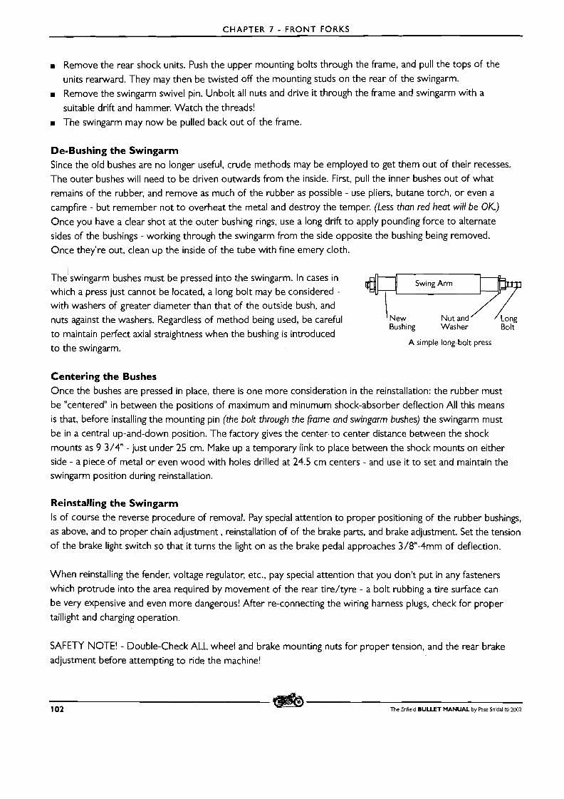
CHAPTER 7 - F R O N T FORKS
m Remove the rear shock units. Push the upper mounting bolts through the frame, and pull the tops of the
units rearward. They may then be twisted off the mounting studs on the rear of the swingarm.
m Remove the swingarm swivel pin. Unbolt all nuts and drive it through the frame and swingarm with a
suitable drift and hammer. Watch the threads!
m The swingarm may now be pulled back out of the frame.
De-Bushing the Swingarm Since the old bushes are no longer useful, crude methods may be employed to get them out of their recesses.
The outer bushes will need to be driven outwards from the inside. First, pull the inner bushes out of what remains of the rubber, and remove as much of the rubber as possible - use pliers, butane torch, or even a
campfire - but remember not to overheat the metal and destroy the temper. (Less than red heat will be OK.) Once you have a clear shot at the outer bushing rings, use a long drift to apply pounding force to alternate
sides of the bushings - working through the swingarm from the side opposite the bushing being removed.
Once they're out, clean up the inside of the tube with fine emery cloth.
s he swing arm bushes must be pressed into the swingarm. In cases in Swing Arm which a press just cannot be located, a long bolt may be considered - with washers of greater diameter than that of the outside bush, and \ / / nuts against the washers. Regardless of method being used, be careful l New Nut and ' sw on^
Bushing Was her Bolt to maintain perfect axial straightness when the bushing is introduced
A simple long-bolt press to the swingarm.
Centering the Bushes Once the bushes are pressed in place, there is one more consideration in the reinstallation: the rubber must
be "centered" in between the positions of maximum and minumum shock-absorber deflection All this means
is that, before installing the mounting pin (the bolt through the frame and swingarm bushes) the swingarm must
be in a central up-and-down position. The factory gives the center-to center distance between the shock
mounts as 9 3/4" - just under 25 cm. Make up a temporary link to place between the shock mounts on either side - a piece of metal or even wood with holes drilled at 24.5 cm centers - and use it to set and maintain the swingarm position during reinstallation.
Reinstalling the Swingarm Is of course the reverse procedure of removal. Pay special attention to proper positioning of the rubber bushings, as above, and to proper chain adjustment , reinstallation of of the brake parts, and brake adjustment. Set the tension
of the brake light switch so that it turns the light on as the brake pedal approaches 3/8"-4mm of deflection.
When reinstalling the fender, voltage regulator, etc., pay special attention that you don't put in any fasteners
which protrude into the area required by movement of the rear tire/tyre - a bolt rubbing a tire surface can
be very expensive and even more dangerous! After re-connecting the wiring harness plugs, check for proper taillight and charging operation.
SAFETY NOTE! - Double-Check ALL wheel and brake mounting nuts for proper tension, and the rear brake
adjustment before attempting to ride the machine!
102 The Enfield BULLET MANUAL by Pete Snidal Q 2002
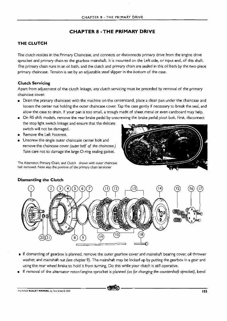
CHAPTER 8 - THE PRIMARY DRIVE
CHAPTER 8 - T H E PRIMARY DRIVE
THE CLUTCH
The clutch resides in the Primary Chaincase, and connects o r disconnects primary drive from the engine drive
sprocket and primary chain to the gearbox mainshaft. I t is mounted on the Left side, o r input end, of this shaft. The primary chain runs in an oil bath, and the clutch and primary chain are sealed in this oil bath by the two-piece primary chaincase. Tension is set by an adjustable steel slipper in the bottom of the case.
Clutch Servicing Apart from adjustment of the clutch linkage, any clutch servicing must be preceded by removal of the primary
chaincase cover.
B Drain the primary chaincase: with the machine on the centerstand, place a clean pan under the chaincase and
loosen the center nut holding the outer chaincase cover. Tap the case gently if necessary to break the seal, and allow the case to drain. If your pan is too small, a trough made of sheet metal or even cardboard may help. On RS shift models, remove the rear brake pedal by unscrewing the brake pedal pivot bolt. First, disconnect the stop light switch linkage and ensure that the delicate switch will not be damaged.
B Remove the Left Footrest. B Unscrew the single outer chaincase center bolt and
remove the chaincase cover (outer half of the chaincase.) Take care not to damage the large O-ring sealing gasket.
The Alternator, Primary Chain, and Clutch - shown with outer chaincase half removed. Note also the position of the primary chain tensioner
Dismantling the Clutch
B If dismantling of gearbox is planned, remove the outer gearbox cover and mainshaft bearing cover, oil thrower
washer, and mainshaft nut (see chapter 9). The mainshaft may be locked up by putting the gearbox in a gear and
using the rear wheel brake t o hold it from turning. Do this while your clutch is still operative.
B If removal of the alternator rotor/engine sprocket is planned (as for changing the countershafi sprocket), bend
The Enfield BULLET MANUAL by Pete Snidal O 2002 103
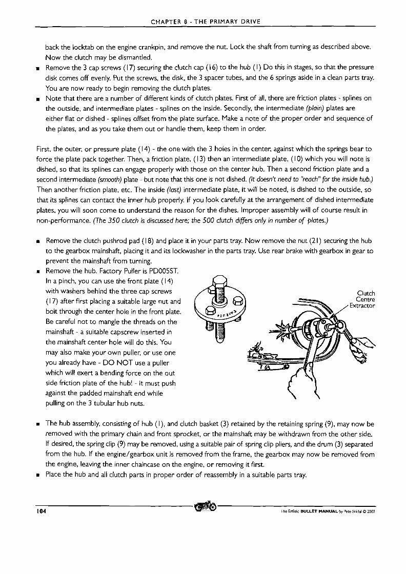
CHAPTER 8 - T H E PRIMARY DRIVE
back the locktab on the engine crankpin, and remove the nut. Lock the shaft from turning as described above.
Now the clutch may be dismantled.
m Remove the 3 cap screws ( 1 7) securing the clutch cap ( 1 6) to the hub (I) Do this in stages, so that the pressure
disk comes off evenly. Put the screws, the disk, the 3 spacer tubes, and the 6 springs aside in a clean parts tray. You are now ready to begin removing the clutch plates. Note that there are a number of different kinds of clutch plates. First of all, there are friction plates - splines on the outside, and intermediate plates - splines on the inside. Secondly, the intermediate (plain) plates are
either flat or dished - splines offset from the plate surface. Make a note of the proper order and sequence of
the plates, and as you take them out o r handle them, keep them in order.
First, the outer, o r pressure plate ( 1 4) - the one with the 3 holes in the center, against which the springs bear to force the plate pack together. Then, a friction plate, (1 3) then an intermediate plate, (1 0) which you will note is
dished, so that its splines can engage properly with those on the center hub. Then a second friction plate and a second intermediate (smooth) plate - but note that this one is not dished. (It doesn't need to "reach" for the inside hub.)
Then another friction plate, etc. The inside (last) intermediate plate, i t will be noted, is dished to the outside, so
that its splines can contact the inner hub properly. If you look carefully at the arrangement of dished intermediate
plates, you will soon come to understand the reason for the dishes. Improper assembly will of course result in
non-performance. (The 350 clutch is discussed here; the 500 clutch differs only in number of plates.)
m Remove the clutch pushrod pad (1 8) and place it in your parts tray. Now remove the nut (2 1 ) securing the hub to the gearbox mainshaft, placing i t and its lockwasher in the parts tray. Use rear brake with gearbox in gear to
prevent the mainshaft from turning. m Remove the hub. Factory Puller is PD005ST.
In a pinch, you can use the front plate ( 1 4) with washers behind the three cap screws
( 1 7) after first placing a suitable large nut and
bolt through the center hole in the front plate. Be careful not t o mangle the threads on the
mainshaft - a suitable capscrew inserted in
the mainshaft center hole will do this. You
may also make your own puller, o r use one
you already have - D O NOT use a puller
which will exert a bending force on the out side friction plate of the hub! - i t must push against the padded mainshaft end while pulling on the 3 tubular hub nuts.
The hub assembly, consisting of hub (I), and clutch basket (3) retained by the retaining spring (9), may now be removed with the primary chain and front sprocket, o r the mainshaft may be withdrawn from the other side. If desired, the spring clip (9) may be removed, using a suitable pair of spring clip pliers, and the drum (3) separated from the hub. If the engine/gearbox unit is removed from the frame, the gearbox may now be removed from
the engine, leaving the inner chaincase on the engine, o r removing it first.
m Place the hub and all clutch parts in proper order of reassembly in a suitable parts tray.
104 The Enfield BULLET MANUAL by Pete Snidal 0 2002
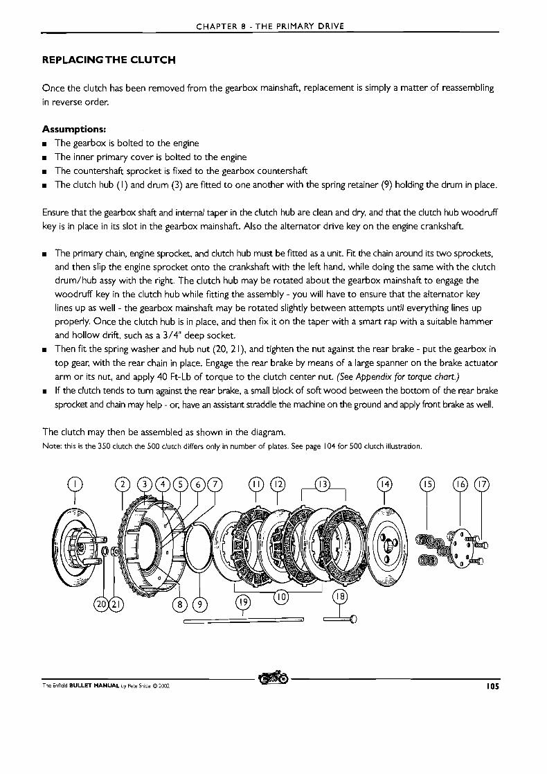
CHAPTER 8 - T H E PRIMARY DRIVE
REPLACING THE CLUTCH
Once the clutch has been removed from the gearbox mainshaft, replacement is simply a matter of reassembling
in reverse order.
Assumptions: H The gearbox is bolted to the engine
H The inner primary cover is bolted to the engine
H The countershaft sprocket is fixed to the gearbox countershaft
H The clutch hub ( I ) and drum (3) are fitted to one another with the spring retainer (9) holding the drum in place.
Ensure that the gearbox shaft and internal taper in the clutch hub are clean and dry, and that the clutch hub woodruff
key is in place in i ts slot in the gearbox mainshaft. Also the alternator drive key on the engine crankshaft.
H The primary chain, engine sprocket, and clutch hub must be fitted as a unit. Fit the chain around its two sprockets, and then slip the engine sprocket onto the crankshaft with the left hand, while doing the same with the clutch
drum/hub assy with the right. The clutch hub may be rotated about the gearbox mainshaft to engage the
woodruff key in the clutch hub while fitting the assembly - you will have to ensure that the alternator key
lines up as well - the gearbox mainshaft may be rotated slightly between attempts until everything lines up
properly. Once the clutch hub is in place, and then fix it on the taper with a smart rap with a suitable hammer and hollow drift, such as a 3/4" deep socket.
H Then fit the spring washer and hub nut (20, 2 l), and tighten the nut against the rear brake - put the gearbox in
top gear, with the rear chain in place. Engage the rear brake by means of a large spanner on the brake actuator
arm or its nut, and apply 40 Ft-Lb of torque to the clutch center nut. (See Appendix for torque chart.)
H If the clutch tends to turn against the rear brake, a small block of soft wood between the bottom of the rear brake
sprocket and chain may help - or, have an assistant straddle the machine on the ground and apply front brake as well.
The clutch may then be assembled as shown in the diagram. Note: this is the 350 clutch the 500 clutch differs only in number of plates. See page 104 for 500 clutch illustration.
The Enfield BULLET MANUAL by Pete Snidal O 2002 105
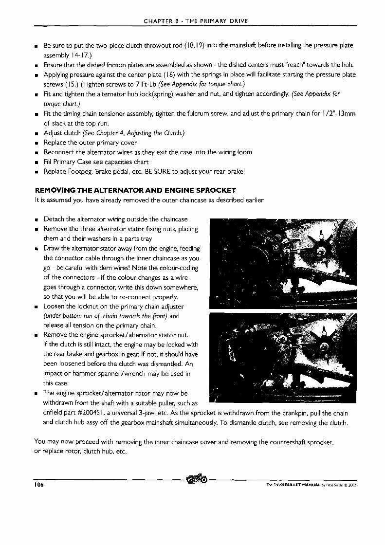
C H A P T E R 8 - T H E PRIMARY DRIVE
m Be sure t o put the two-piece clutch throwout rod ( 1 8,19) into the mainshaft before installing the pressure plate
assembly 14- 17.) m Ensure that the dished friction plates are assembled as shown - the dished centers must "reach" towards the hub.
m Applying pressure against the center plate (1 6) with the springs in place will facilitate starting the pressure plate
screws (1 5.) (Tighten screws to 7 Ft-Lb (See Appendix for torque chart.) B Fit and tighten the alternator hub lock(spring) washer and nut, and tighten accordingly. (See Appendix for
torque chart.)
m Fit the timing chain tensioner assembly, tighten the fulcrum screw, and adjust the primary chain for 1 /2"- 13mm
of slack at the top run. m Adjust clutch (See Chapter 4. Adjusting the Clutch.)
m Replace the outer primary cover m Reconnect the alternator wires as they exit the case into the wiring loom
m Fill Primary Case see capacities chart m Replace Footpeg, Brake pedal, etc. BE SURE t o adjust your rear brake!
REMOVING THE ALTERNATOR A N D ENGINE SPROCKET I t is assumed you have already removed the outer chaincase as described earlier
m Detach the alternator wiring outside the chaincase
m Remove the three alternator stator fixing nuts, placing
them and their washers in a parts tray
Draw the alternator stator away from the engine, feeding
the connector cable through the inner chaincase as you
go - be careful with dem wires! Note the colour-coding
of the connectors - if the colour changes as a wire
goes through a connector, write this down somewhere, so that you will be able t o re-connect properly.
m Loosen the locknut on the primary chain adjuster (under bottom run of chain towards the front) and release all tension on the primary chain.
m Remove the engine sprocket/alternator stator nut.
If the clutch is still intact, the engine may be locked with
the rear brake and gearbox in gear. If not, i t should have been loosened before the clutch was dismantled. An
impact o r hammer spanner/wrench may be used in
this case.
m The engine sprocket/alternator rotor may now be
withdrawn from the shaft with a suitable puller, such as
Enfield part #2004ST, a universal 3-jaw, etc. As the sprocket is withdrawn from the crankpin, pull the chain
and clutch hub assy off the gearbox mainshaft simultaneously. To dismantle clutch, see removing the clutch.
You may now proceed with removing the inner chaincase cover and removing the countershaft sprocket, or replace rotor, clutch hub, etc.
106 The Enfield BULLET MANUAL by Pete Snidal O 2002
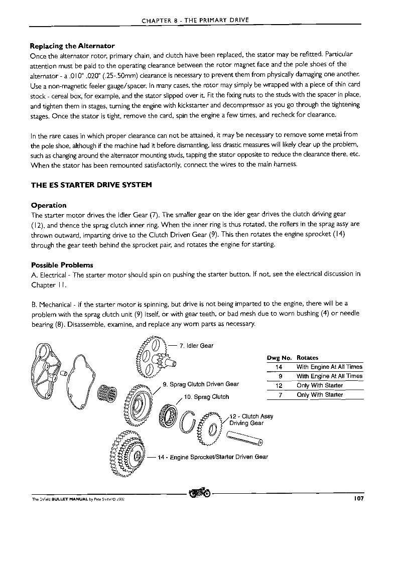
CHAPTER 8 - THE PRIMARY DRIVE
Replacing the Alternator Once the alternator rotor, primary chain, and clutch have been replaced, the stator may be refitted. Particular
attention must be paid to the operating clearance between the rotor magnet face and the pole shoes of the alternator - a .O 10"-.020 (.25-.50mm) clearance is necessary to prevent them from physically damaging one another.
Use a non-magnetic feeler gauge/spacer. In many cases, the rotor may simply be wrapped with a piece of thin card stock - cereal box, for example, and the stator slipped over it. Fit the fixing nuts to the studs with the spacer in place,
and tighten them in stages, turning the engine with kickstarter and decompressor as you go through the tightening stages. Once the stator is tight, remove the card, spin the engine a few times, and recheck for clearance.
In the rare cases in which proper clearance can not be attained, it may be necessary to remove some metal from the pole shoe, although if the machine had it before dismantling, less drastic measures will likely clear up the problem, such as changing around the alternator mounting studs, tapping the stator opposite to reduce the clearance there, etc. When the stator has been remounted satisfactorily, connect the wires to the main harness.
THE ES STARTER DRIVE SYSTEM
Operation The starter motor drives the ldler Gear (7). The smaller gear on the ider gear drives the clutch driving gear
(1 2), and thence the sprag clutch inner ring. When the inner ring is thus rotated, the rollers in the sprag assy are thrown outward, imparting drive to the Clutch Driven Gear (9). This then rotates the engine sprocket (1 4) through the gear teeth behind the sprocket pair, and rotates the engine for starting.
Possible Problems A. Electrical - The starter motor should spin on pushing the starter button. If not, see the electrical discussion in Chapter I I.
B. Mechanical - If the starter motor is spinning, but drive is not being imparted to the engine, there will be a problem with the sprag clutch unit (9) itself, or with gear teeth, or bad mesh due to worn bushing (4) o r needle bearing (8). Disassemble, examine, and replace any worn parts as necessary.
,10. S~raa Clutch 7 Only With Starter
- 7. ldler Gear
Dwg No. Rotates
14 With Engine At All Times 9 With Engine At All Times
, 9. Sprag Clutch Driven Gear 12 Onlv With Starter
.
12 - Clutch ASSY Driving Gear
e SprocketfStarter Driven Gear
The Enfield BULLET MANUAL by Pete Snidal O 2002 107
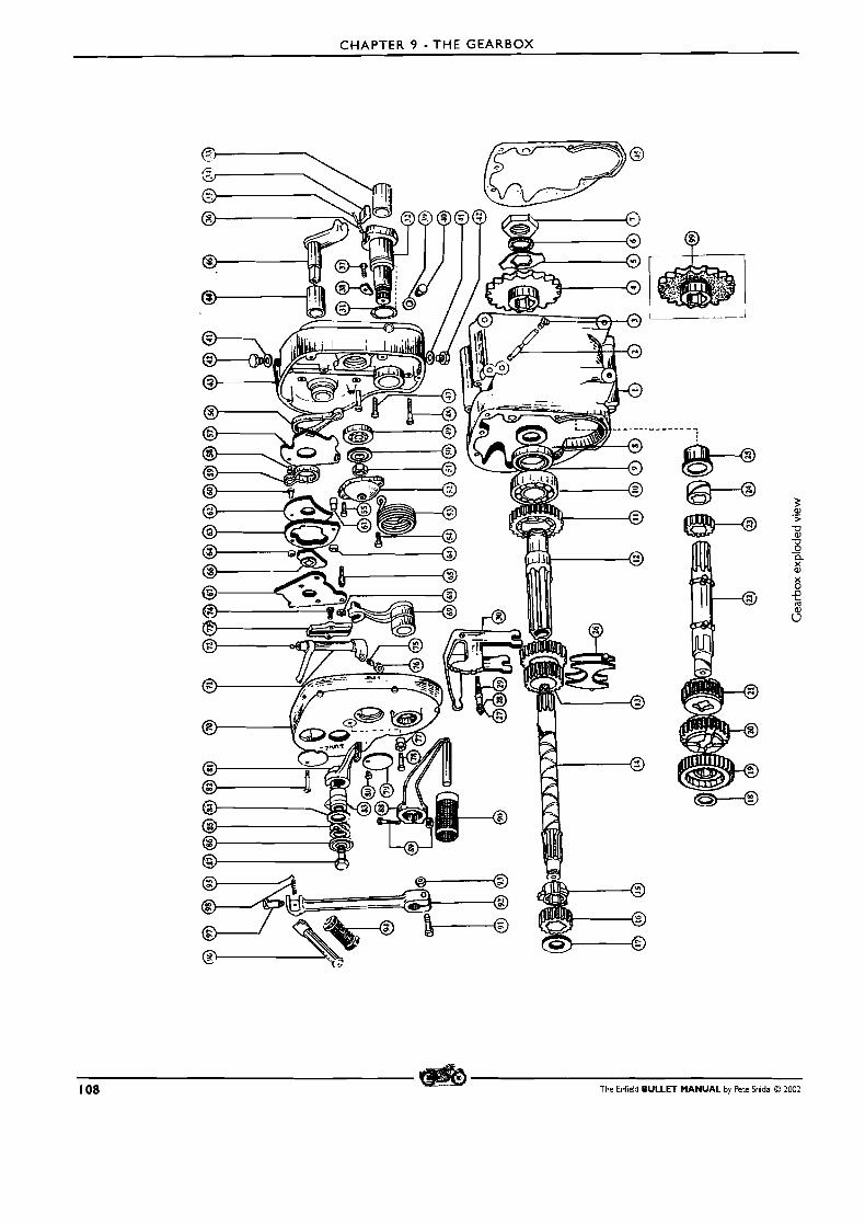
CHAPTER 9 - THE GEARBOX
108 The Enfield BULLET MANUAL by Pete Snidal O 2002
CHAPTER 9 - THE GEARBOX
CHAPTER 9 - T H E GEARBOX
ADJUSTMENT O F THE NEUTRAL FINDER
The neutral finder rotates the gear selector shaft in a clockwise direction - towards the I st gear end of the movement.
It wouldn't stop until it got to I st, except for the stop provided by the neutral finder adjustment collar on the
front of the outer cover.
To check adjustment, first check that the indicator pointer is at the "NW between " I " and "2". Straddle the motorcycle,
and rock it back and forth on the ground while pressing on the Neutral Finder lever with the right heel. When it
stops, the gearbox should be in neutral. Check by pulling in the clutch lever and depressing the kickstarter. If the
machine is in gear, it will move forward. If so, adjustment should be done:
m The stop collar is eccentric; loosening the securing bolt allows it to be turned, tightening the bolt locks it in place.
m Put the machine on the center stand
m Loosen the stop collar bolt and rotate the collar for maximum slack - max runout to the bottom.
m Then take the machine off the stand and straddle it.
m Rock the machine back and forth while working your way up to I s t gear, then down to second, and then
back until you feel the neutral notch.
m Put the machine back on the stand
Push lightly down on the neutral finder lever until it stops.
m Then turn the neutral finder eccentric collar in either direction until it contacts the underside of the neutral
finder lever.
m Tighten the fixing bolt and test. Repeat until done.
REMOVAL A N D REPLACEMENT O F COUNTERSHAFT SPROCKET
Removal m Remove the outer primary cover and clutch
m Remove the engine drive sprocket/alternator rotor
m Remove all remaining fasteners holding the inner primary case half to the engine. Remove the case half.
When removing the inner primary cover, take moves to avoid damage to the gearbox mainshaft oilseal.
There is a factory tool which can be placed over the mainshaft - its splines will almost certainly score the
inner lip of the seal if the case is drawn over it in either direction. A thin piece of sheetmetal or plastic may
be wrapped around the splines, and slipped inside the seal before withdrawing the inner case. Use this
method also when re-fitting the case.
m Bend back the safety tab on the countershaft nut, and loosen this nut. Lock the countershaft by applying rear
brake with rear chain in place.
m Remove the rear chain from the sprocket. Break the chain at the master link - it may be left dangling off the
rear sprocket. If you are changing the size of the countershaft sprocket, the chain will have to be adjusted.
m Draw the countershaft sprocket off the countershaft. You may have to cap the end of the mainshaft to avoid
thread damage, and use a suitable 2 or 3 jaw puller
m The countershaft may now be withdrawn from inside the gearbox, or the sprocket may be replaced and the
primary drive reassembled.
The Enfield BULLET MANUAL by Pere Snidai O 2002 109
CHAPTER 9 - THE GEARBOX
Reassembly Reassemble in reverse order of disassembly. m (optional) Replace the rear chain and adjust the rear brake pedal if Left Foot shift.
m Tighten the countershaft sprocket nut as tightly as possible, locking it with the rear brake and chain in place
over the sprocket. Be sure to use the locking washer, bending the tab over a suitable flat on the washer. Use
a fresh bend on the washer. The brake may be locked with a spanner on the activator arm if the brake pedal is not in place. A block of wood in the lower run of the chain against the sprocket may be required, or an
assistant straddling the machine on the ground and holding on the front brake.
m When re-fitting the inner case, pay special attention to the centering of the rear oil seal around the gearbox mainshaft. Be especially carful not to damage the inside of the seal as it passes over the gearbox mainshaft - the splines can easily score o r cut the inner lip of the seal. There is a special factory tool, the Gearbox Mainshaft Seal Protection Sleeve (PD 074ST), designed to combat this problem, although a bodge can be done using a thin piece of sheet metal.
Once the inner case has been put in place. snug the retaining bolts up, and then move the case around until you have the best center you can get of the seal around the gearbox mainshaft - if off-center, it will leak, and the
case will generally be found to have some slack. Once you've established the center, tighten up the fixing bolts.
m As you fit the alternator stator, feed the connector cable through the inner chaincase half and route it to the
proper place for reconnection. m When re-fitting the alternator stator, ensure with a non-magnetic feeler gauge that there is a minimum of
.006" - .15mm at all points. Rotate the engine to ensure that this gap exists at all times. Damage to pole shoes
and the rotor itself will result if this clearance is not maintained. Check again after tightening the mounting nuts. m When the clutch has been reassembled, (be sure to tighten the center nut as tightly as possible with the wheel
locked as above), adjust the linkage and try it out before proceeding. m Adjust the primary chain with the tensioner for 1 /4" - 6mm of play at the center of the top run. Kick the
engine over a few times and check the chain at various places of rotation. m When the outer chaincase cover has been re-fitted, refill the chaincase with clean 20-20W or Automatic
Transmission Fluid (preferably Type F) to the level of the level plug in the outer cover.
IMPORTANT SAFETY NOTE: Be sure to adjust the rear brake pedal before operating the machine. Check also the
rear chain adjustment - if you have changed the size of the countershaft sprocket, the chain will have had to be adjusted.
REMOVING THE OUTER COVER
If complete stripping of the gearbox is intended, ie removal of the gearset and mainshaft, the clutch should be
removed before proceeding. The first step in any gearbox work will be removal of the outer cover. I t will be well t o refer to the diagram, before proceeding.
First, remove the neutral finder lever assy (8 1-87) from the shifter shaft (46). Identify each part on the diagram, and place them in order in the parts tray - a piece of wire or bag tie through them all would be a good idea. The neutral finder stop assy (77, 78) may be left in place. Then, remove the gear change lever (RH shifi models), and kickstarter lever.
110 The Enfield BULLET MANUAL by Pete Snidal O 2002
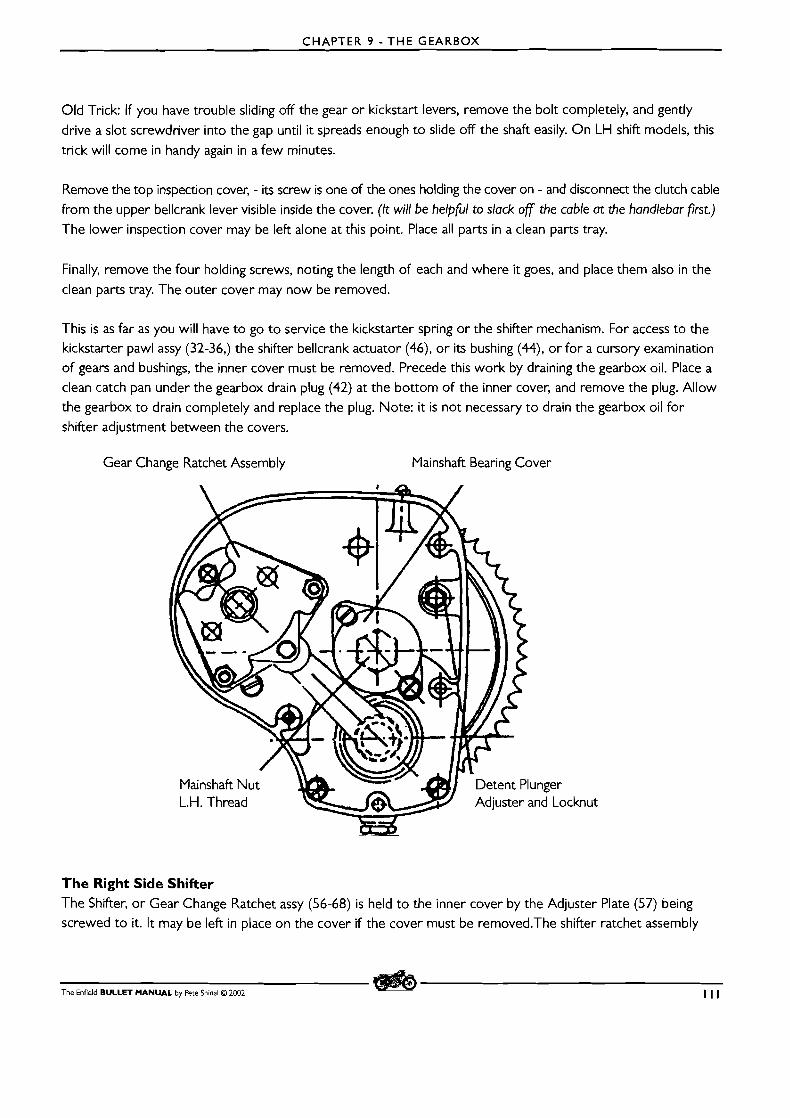
CHAPTER 9 - THE GEARBOX
Old Trick: If you have trouble sliding off the gear or kickstart levers, remove the bolt completely, and gently
drive a slot screwdriver into the gap until it spreads enough to slide off the shaft easily. On LH shift models, this trick will come in handy again in a few minutes.
Remove the top inspection cover, - its screw is one of the ones holding the cover on - and disconnect the clutch cable from the upper bellcrank lever visible inside the cover. (It will be helpful to slack of the cable at the handlebar first.)
The lower inspection cover may be left alone at this point. Place all parts in a clean parts tray.
Finally, remove the four holding screws, noting the length of each and where it goes, and place them also in the
clean parts tray. The outer cover may now be removed.
This is as far as you will have to go to service the kickstarter spring or the shifter mechanism. For access to the kickstarter pawl assy (32-36,) the shifter bellcrank actuator (46), or its bushing (44), or for a cursory examination of gears and bushings, the inner cover must be removed. Precede this work by draining the gearbox oil. Place a clean catch pan under the gearbox drain plug (42) at the bottom of the inner cover, and remove the plug. Allow
the gearbox to drain completely and replace the plug. Note: it is not necessary to drain the gearbox oil for shifter adjustment between the covers.
Gear Change Ratchet Assembly Mainshaft Bearing Cover
The Right Side Shifter The Shifter, or Gear Change Ratchet assy (56-68) is held to the inner cover by the Adjuster Plate (57) being screwed to it. It may be left in place on the cover if the cover must be removed.The shifter ratchet assembly
The Enfield BULLET MANUAL by Pete Snidal @ 2002 I l l

CHAPTER 9 - THE GEARBOX
(57-67), with the Outer Actuator (69) shaft, may be left in place on the kickstarter shaft (32). In the case of the
Left Side shift, you should examine all bushings, pins, etc. in the mechanism from the change pedal to the final actuator shaft into the rear of the inner cover. Owners report few difficulties with the bushings supporting the actual
crossover shaft, but the design leaves something to be desired with the pins in the parallelogram arrangement between the pedal shaft and the crossover shaft. There are some improvement kits available, - see your dealer - o r
many owners have elected to go back to the original design of the Right Foot Shift. A kit is also available for this
conversion. The drawback is in learning how to ride with right-foot shifting, the advantage is in the remarkably
more positive gearchanging due to the elimination of so many parts between the foot and the ratchet.
Removing the Inner Cover THE LEFT SIDE SHIFTER
With the LH (Continental and NA) shift mechanism, the internal shift actuator lever is moved by the LH (Continental/US)
external shift linkage by means of a shaft coming in through the rear of the inner case. Before the inner cover is
removed, the shaft clamp must be loosened, and the LH actuator removed, in order to remove the circlip on
the shaft just behind the lever. You will probably need t o spread the clamp. In order to remove the actuator, it
will also be necessary temporarily to remove the stopplate (67). Remove the two cap nuts holding the plate, withdraw the actuator, and refit the nuts to hold the inner and outer ratchets in place.
Both Shifters To remove the inner cover, the fixing screws must be removed. The mainshaft bearing cover (52) will be seen to be held in place by two screws, one of which is used as the anchor for the kickstarter return spring. Remove these two screws, supporting the end of the spring with a suitable tool such as needlenose pliers as you take out i ts screw, and relieve the spring pressure gradually. Place the cover and its screws in the parts tray, and then
unscrew the nut (5 1) and washer (50) on the end of the mainshaft. Note the mainshaft nut (5 1) is LEFT HAND
TH READ!
Remove all cover fixing screws, whether slot head, philips,
o r cap screw (hex head). This will make it possible to pull off the inner cover.
NB:- note the detent plunger adjuster is also a screw head,
but held in place by a locknut. As it has no part in retaining the inner gearbox cover to the gearbox case, this may be left in place. , or removed as a unit. (27,28,29) If removal is chosen, first make a note of the angle of the screw slot relative to
the floor. Then, loosen the locknut, and screw down the
adjuster gently , counting the number of half-turns until it
stops. Make a note of this number for replacement purposes.
Then unscrew it until the assembly is released, and place it in your parts tray. \
Shifter Actuator Lever \ Shifter Shaft Clamp
Drawing Anomaly A t some time in the history, the factory changed the manner of fixing the pawl shaft stop (38) in place, changing
112 The Enfeld BULLET MANUAL by Pete Snidal O 2002
CHAPTER 9 - THE GEARBOX
from bolting through the stop and into threads in the case cover from the inside (with bolt shown as - 371, and
bolting instead through the case cover from the outside and into threads in the shaft stop inside. If you have one
of these, there will be an "extra" screw, not on the periphery of the case cover joint, but below and to the rear
of the mainshaft bearing - on the upper periphery of the kickstarter shaft (32.) Leave this screw in place.
Breaking the Joint You may now break the joint between the inner cover and the gearbox case. First, test to make sure that all fasteners are removed. Lightly tap the cover on the top, bottom, and sides with a block of wood and hammer. You may also find it helpful t o tap it outwards from behind with a suitable block of wood from over top of the clutch cover or from the rear of the gearbox.
D O NOT use excessive force. The cover should come fairly easily - if in doubt, look again t o ensure that all fas-
teners have been removed. There are none coming in from the back.
Mainshaft Bearing In many instances, the inner race of the mainshaft bearing (49) will be a very tight fit on the end of the mainshaft
( 1 4). In extreme cases, a puller could be made up, a plate which would be held across the front of the inner case
by means of the outer case mounting screws, with a nut and bolt applying pressure against the mainshaft.
However, in most cases, merely placing the nut on the end of the shaft t o protect the threads, and applying
pulling force to the outsides of the case cover, while tapping the mainshaft end with a hammer and soft (aluminum or brass) drift will suffice.
When the cover is loose, carefully pry it away from the gearbox case - D O NOT damage the joint surfaces; they must maintain oil tightness when this is all over.
You want to leave the kickstarter shaft (32) and shifter bellcrank shaft (46) in place in the gearbox as you pull
the cover off. So, using the thumbs, apply pressure to these shafts as you pull the cover off with the fingers of
both hands. When the cover is off, you will be ready to service the components inside the gearbox itself. Similar
pressure may be appropriate for the mainshaft to come through its bearing.
The Inner Gearbox parts will now be accessible for service.
S'TRIPPING THE GEARBOX
The entire gearset may be removed and replaced without removing the gearbox from the engine o r out of the frame, although the shifter bellcrank (30) must be left in place, since it is retained by its mounting pin (2) which is
accessible only with gearbox removed from engine. This will allow examination and/or replacement of all gears, pinions, shafts, bushes, or bearings in the gearbox, as well as the shifter fork (26.) All the wear pieces.
The clutch assy must be off in order to pull out the mainshaft, however. The countershaft sprocket (4) must also
be removed in order t o remove the countershaft ( 1 2), as well as the main shaft I st gear pinion ( I I) and the
countershaft bearing (4) and oil seal (8.)
The Enfield BULLET MANUAL by Pete Snidal O 2002 113
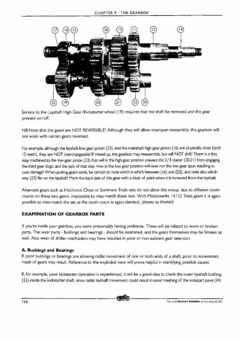
CHAPTER 9 - THE GEARBOX
Service t o the Layshaft High Gear/Kickstarter wheel (1 9) requires that the shaft be removed and the gear pressed on/off.
NB:Note that the gears are NOT REVERSIBLE! Although they will allow improper reassembly, the gearbox will not work with certain gears reversed.
For example, although the layshaft low gear pinion (23), and the mainshaft high gear pinion (1 6) are physically close (both
15 teeth), they are NOT interchangeable! If mixed up, the gearbox may reassemble, but will NOT shift! There is a thin step machined to the low gear pinion (23) that will in the high gear position prevent the 2/3 cluster (20,2 1 ) from engagng the third gear dogs. and the lack of that step now in the low gear position will over run the low gear spur, resulting in case damage! When putting gears aside, be certain to note which is which between (1 6) and (23), and note also which way (23) fits on the layshaft! Mark the back side of this gear with a daub of paint when it is removed from the layshaft.
Alternate gears such as Hitchcock Close or Sommers Trials sets do not allow this mixup, due to different tooth
counts on these two gears. impossible t o miss-match these two. With Motorwerks 14/25 Trials gears it is again possible to miss-match the set as the tooth count is again identical. (thanks to Martin!)
EXAMINATION OF GEARBOX PARTS
If you're inside your gearbox, you were presumably having problems. These will be related t o worn o r broken parts. The wear parts - bushings and bearings - should be examined, and the gears themselves may be broken as
well. Also wear of shifter mechanism may have resulted in poor o r non-existent gear selection.
A. Bushings and Bearings If poor bushings or bearings are allowing radial movement of one or both ends of a shaft, poor t o nonexistent mesh of gears may result. Reference to the exploded view will prove helpful in identifying possible causes.
If, for example, poor kickstarter operation is experienced, it will be a good idea to check the outer layshaft bushing
(33) inside the kickstarter shaft, since radial layshaft movement could result in poor meshing of the kickstart pawl (34)
114 The Enfield BULLET MANUAL by Pete Snidal O 2002
CHAPTER 9 - THE GEARBOX
with the layshaft high gear/kickstart wheel ( 1 9.) Furthermore, erosion of this bushing could be expected to pollute the kickstart pawl/plunger/spring (34-36) pocket in the shaft, causing the pawl to bind up and resulting in faulty
engagement. Check this bushing by stripping the pawl parts out, being careful to place them in your clean parts tray, and fitting the kicker shaft to the end of the layshaft, and then rocking the outer end radially. If excessive looseness
is detected, the bushing should be replaced. In the case of the home workshop mechanic, it will have t o be done at a machine shop, o r the entire kicker shaft replaced, since getting this "blind" bushing out can be tricky.
Enrichment Exercise Want t o try? First, prepare a drift the diameter of the inside of the bushing hole. (Shafl diameter +, since bushing
is worn.) Then, pack the inside of the bushing with heavy grease. Support the kicker shaft in a suitable vice, and apply serious hammer blows to the drift inside the worn bushing. Hydraulic pressure transmitted by the grease should force the bushing out past the drift. Easy, huh?
The kickstarter shaft itself is supported by the gearshift actuator, (69) in the RHS models, and if this bush is suitably
worn, poor kickstarter operation (as well as other complications from loose outer layshafl support) could be the result. Although strictly speaking, the actuator is not solely a bushing, replacement could be necessary to tighten things
up. (On LHS models, the bushing in the inner case, which supports the Kicker shafl, may be too loose and require
replacement.) The KS Oil Seal (3 1 ) should also be replaced at every opportunity.
The mainshaft outer bearing (49) should be examined closely as well, and replaced if any sign of noisiness o r looseness is shown. Clean the bearing thoroughly and examine both races and the balls with a magnifying glass
and a strong light. All surfaces must be smooth and shiny.lf any sign of dullness is present, replace the bearing.
The actuator lever (46) shaft bushing (44) can also result in poor gearchanging performance if worn (RHS models).
This should be checked by attempting to rock the shaft radially in the bush, and if looseness is encountered, the bush should be replaced. Heating the inner cover to "spitting hot" with a propane torch, and driving it out with a
stepped drift, followed by driving the chilled new one back in will be the simplest and best way to do this. In cases of complete gearbox dismantling, when the geanets are removed, it is possible to examine the mainshaft main bearing (1 O), the layshaft inner bush (25).
B. Gears, Dogs, and Shafts The basic physical shape of the gear teeth, dog slots, the dogs themselves on the shafts, the splines, both internal and external, must be fairly close to original. Examine also the splines on the shafts for straightness - and "cricks" in them due to excessive torque having been applied (unlikely in the stock Bullet, but possible in a big twin) will make
for impossible or difficult gearchanges. The gear teeth themselves must not have rounded corners or missing
pieces. Replace any doubtful parts with new or good used ones from your dealer.
Forks and Sliders The Shifter Fork (26) is a wear part. Look for excessive clearances between it and the slider gears (20,2 1). Place it into the gears, engaging the flanges, outside the gearbox, and rock it axially. Too much slop indicates replacement is required.
Reassembly Once all the parts have checked out or been replaced, reassembly is the next order of business.
The Enfield BULLET MANUAL by Pete Snidal O 2002 115
CHAPTER 9 - THE GEARBOX
CORRECTING FAULTY GEARCHANGING
If trouble is experienced changing gears, first review the advice on changing gear in Chapter 2. 'Then, check to see that there is no external binding of the neutral finder or gearchange levers on the gearbox cover, exhaust
pipe, etc. Following this, a test ride should be done. If you then decide to "go in," f i rs t take the time to go over this section, and to get an idea of just how the shifter mechanism works.
Test Riding Before delving further into gear changing troubles, the wise owner will do a test ride to learn as much as possible
in pinpointing the difficulties. Gear changing problems will manifest themselves in a few different ways.
"Firing" or "Popping" out of gear once one has been found
Going past the next gear on changes, into a false neutral Failing to make it far enough into the next gear on changes, reaching only into a false neutral Either of the above, but only in one direction - upshifting or downshifting Poor control of the mechanism due to binding on externals, or sloppiness of the quickly-wearing LH shift spooge
Sloppy L H Shift Linkage The "Continental" Left Hand shift linkage, also shipped to the US and Canada, has met with a great deal of criticism from owners. It is not to be denied that it is improvable, either by rebushing (kits are available from your dealer) or "de-evolving" back to the original RHS setup which is still supplied in the vast majority of Bullets made in India. If re-bushing is chosen, pay particular attention to the rivets in the parallelogram setup at the end of the footshift lever.
Determining Faulty Detent Plunger Action If the detent plunger is faulty, but the ratchet mechanism is taking the bellcrank to the correct position on gear changes, you will experience proper changes from one gear to another (once you've found the "one gear'? but it won't stay in that
gear for long, "firing" out of gear as you apply power. The two extremes of the movement - I s t and 4th, will be found to work just fine if you maintain pressure on the gear lever, upward or downward, as the case may be, but when you make the change from 4th to 3rd, or from I s t to second, it will go to the next chosen gear, but not stay there. This is an obvious case of the detent plunger failing to hold the bellcrank in position, indicating a need for plunger adjustment.
Going Past or Not Reaching Gears on Changes FAULTY SHIFTER PLATE ADJUSTMENT The position of the shifter plate determines whether or not the shifter ratchet returns to center, so that changes in either direction will equally engage teeth to impart movement.
If the ratchet is not providing enough movement in the upshift direction there will be consistent trouble upshifting,
ie getting from 3rd to 4th - it will stop in the false neutral between these gears. This can be due to the ratchet
not returning to proper center, which would be remedied by rotating the adjuster plate anti-clockwise. In these
cases, it will almost always work properly in the other direction - there will not be too much movement in the
opposite direction, since the shifter stop(s) will prevent excess movement.
116 The Enfield BULLET MANUAL by Pete Snidal O 2002
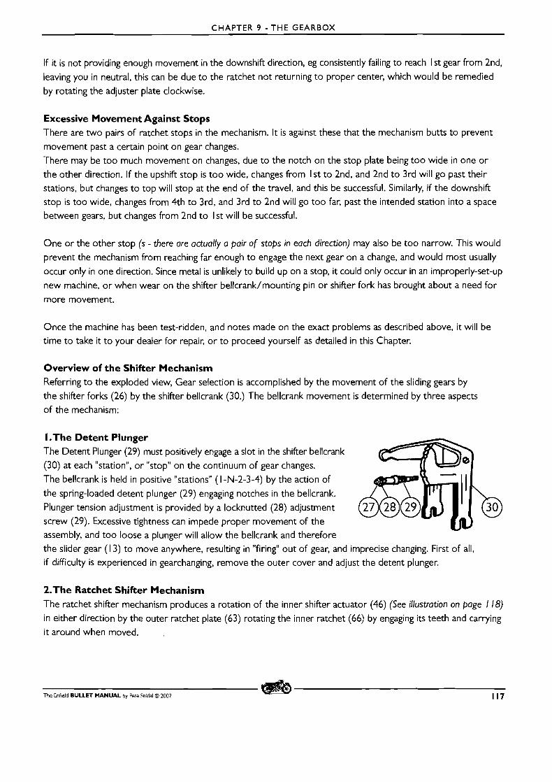
CHAPTER 9 - THE GEARBOX
If it is not providing enough movement in the downshift direction, eg consistently failing to reach I st gear from 2nd, leaving you in neutral, this can be due to the ratchet not returning t o proper center, which would be remedied
by rotating the adjuster plate clockwise.
Excessive Movement Against Stops There are two pairs of ratchet stops in the mechanism. It is against these that the mechanism butts to prevent movement past a certain point on gear changes.
There may be too much movement on changes, due to the notch on the stop plate being too wide in one or the other direction. If the upshift stop is too wide, changes from I s t to 2nd, and 2nd to 3rd will go past their
stations, but changes to top will stop at the end of the travel, and this be successful. Similarly, if the downshift stop is too wide, changes from 4th to 3rd, and 3rd to 2nd will go too far, past the intended station into a space between gears, but changes from 2nd t o I s t will be successful.
One or the other stop (S - there ore actually a pair of stops in each direction) may also be too narrow. This would
prevent the mechanism from reaching far enough to engage the next gear on a change, and would most usually
occur only in one direction. Since metal is unlikely to build up on a stop, it could only occur in an improperly-set-up
new machine, or when wear on the shifter bellcrank/mounting pin o r shifter fork has brought about a need for
more movement.
Once the machine has been test-ridden, and notes made on the exact problems as described above, it will be time to take it t o your dealer for repair, or to proceed yourself as detailed in this Chapter.
Overview of the Shifter Mechanism Referring to the exploded view, Gear selection is accomplished by the movement of the sliding gears by the shifter forks (26) by the shifter bellcrank (30.) 'The bellcrank movement is determined by three aspects of the mechanism:
I .The Detent Plunger The Detent Plunger (29) must positively engage a slot in the shifter bellcrank (30) at each "station", or "stop" on the continuum of gear changes. The bellcrank is held in positive "stations" (1 -W-2-3-4) by the action of
the spring-loaded detent plunger (29) engaging notches in the bellcrank.
Plunger tension adjustment is provided by a locknutted (28) adjustment screw (29). Excessive tightness can impede proper movement of the assembly, and too loose a plunger will allow the bellcrank and therefore the slider gear (1 3) to move anywhere, resulting in "firing" out of gear, and imprecise changing. First of all,
if difficulty is experienced in gearchanging, remove the outer cover and adjust the detent plunger.
2.The Ratchet Shifter Mechanism The ratchet shifter mechanism produces a rotation of the inner shifter actuator (46) (See illustration on page 1 18) in either direction by the outer ratchet plate (63) rotating the inner ratchet (66) by engaging its teeth and carrying it around when moved.
The Enfield BULLET MANUAL by Pete Snidal O ZOO2 117

CHAPTER 9 - THE GEARBOX
After each movement of the change lever, the mechanism must be returned to center by the Outer Ratchet Return Spring (59). This center is determined by the position of the Adjuster Plate (57) relative to the inner
case cover, t o which it is bolted through adjustable slots. Here are photos of properly-centered ratchet action
(shown with stop plate removed, gearbox in 3rd):
The Ratchet Ring rotates around the rivet holding the upper stop pin
Ratchet ring catching inner ratchet for a downshift to 2nd gear Ratchet ring catching inner ratchet for an upshift from 3rd to top (CW Rotation) (CCW Rotation)
Right: View with the stop plate in place. Between gear changes, shifter plate centered by spring, both sets of teeth equally disengaged, stop pins in center of recesses. The ratchet return
spring (59) has centered the mechanism properly, indicating proper setting of the adjuster plate (57).
3.The Stop Pins and Plate In the case of each gearchange, the movement of the shifter linkage is limited by the action of the stop pins (64) coming to rest
against the relevant edges of their recesses in the Stop Plate (67).
118 The Enfield BULLET MANUAL by Pete Sfidal O 2002
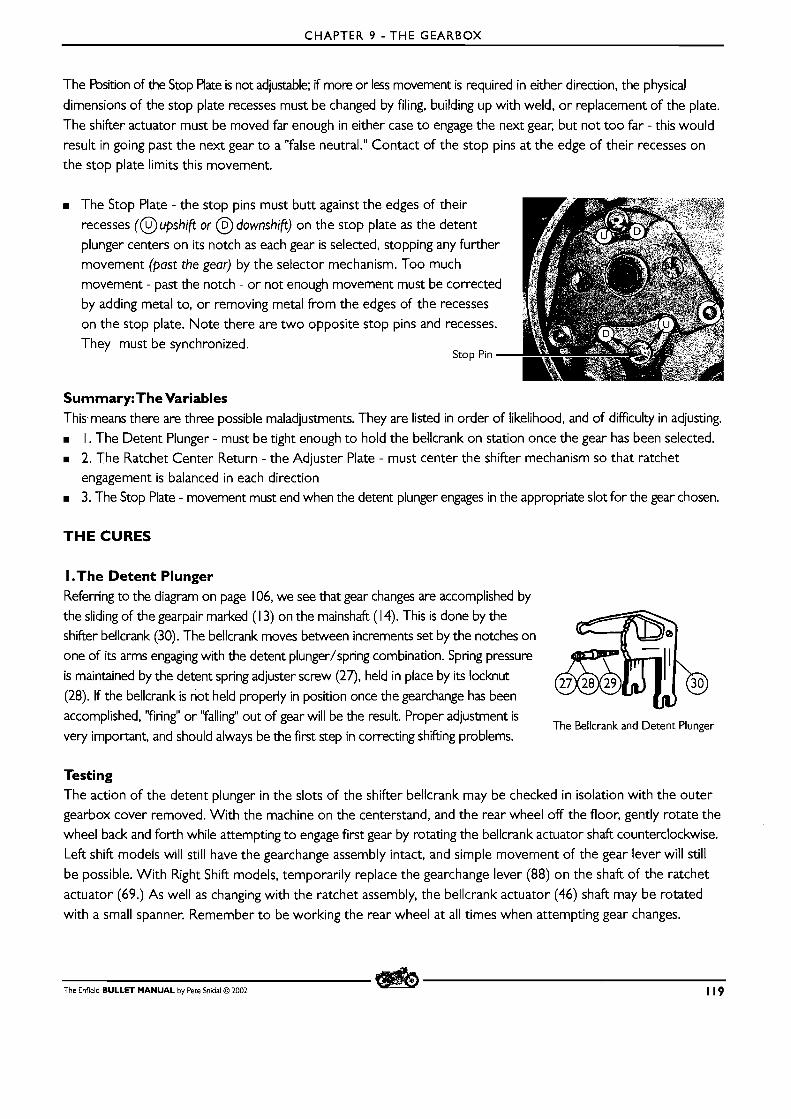
CHAPTER 9 - THE GEARBOX
The Position of the Stop Plate is not adjustable; if more or less movement is required in either direction, the physical
dimensions of the stop plate recesses must be changed by filing, building up with weld, or replacement of the plate.
The shifter actuator must be moved far enough in either case to engage the next gear, but not too far - this would
result in going past the next gear to a "false neutral." Contact of the stop pins at the edge of their recesses on
the stop plate limits this movement.
The Stop Plate - the stop pins must butt against the edges of their
recesses (@upshift or @ downshift) on the stop plate as the detent
plunger centers on its notch as each gear is selected, stopping any further
movement (past the gear) by the selector mechanism. Too much
movement - past the notch - or not enough movement must be corrected
by adding metal to, or removing metal from the edges of the recesses
on the stop plate. Note there are two opposite stop pins and recesses.
They must be synchronized. Stop Pin -
Summary:The Variables This means there are three possible maladjustments. They are listed in order of likelihood, and of difficulty in adjusting.
I . The Detent Plunger - must be tight enough to hold the bellcrank on station once the gear has been selected.
2. The Ratchet Center Return - the Adjuster Plate - must center the shifter mechanism so that ratchet
engagement is balanced in each direction 3. The Stop Plate - movement must end when the detent plunger engages in the appropriate slot for the gear chosen.
THE CURES
I .The Detent Plunger Referring to the diagram on page 106, we see that gear changes are accomplished by
the sliding of the gearpair marked (1 3) on the mainshaft (1 4). This is done by the
shifter bellcrank (30). The bellcrank moves between increments set by the notches on
one of its arms engaging with the detent plunger/spring combination. Spring pressure
is maintained by the detent spring adjuster screw (27), held in place by its locknut
(28). If the bellcrank is not held properly in position once the gearchange has been
accomplished, "firing" or "falling" out of gear will be the result. Proper adjustment is The Bellcrank and Detent Plunger
very important, and should always be the first step in correcting shifting problems.
Testing The action of the detent plunger in the slots of the shifter bellcrank may be checked in isolation with the outer
gearbox cover removed. With the machine on the centerstand, and the rear wheel off the floor, gently rotate the wheel back and forth while attempting to engage first gear by rotating the bellcrank actuator shaft counterclockwise.
Left shift models will still have the gearchange assembly intact, and simple movement of the gear lever will still
be possible. With Right Shift models, temporarily replace the gearchange lever (88) on the shaft of the ratchet
actuator (69.) As well as changing with the ratchet assembly, the bellcrank actuator (46) shaft may be rotated
with a small spanner. Remember to be working the rear wheel at all times when attempting gear changes.
The Enfield BULLET MANUAL by Pete Snidal O 2002 119
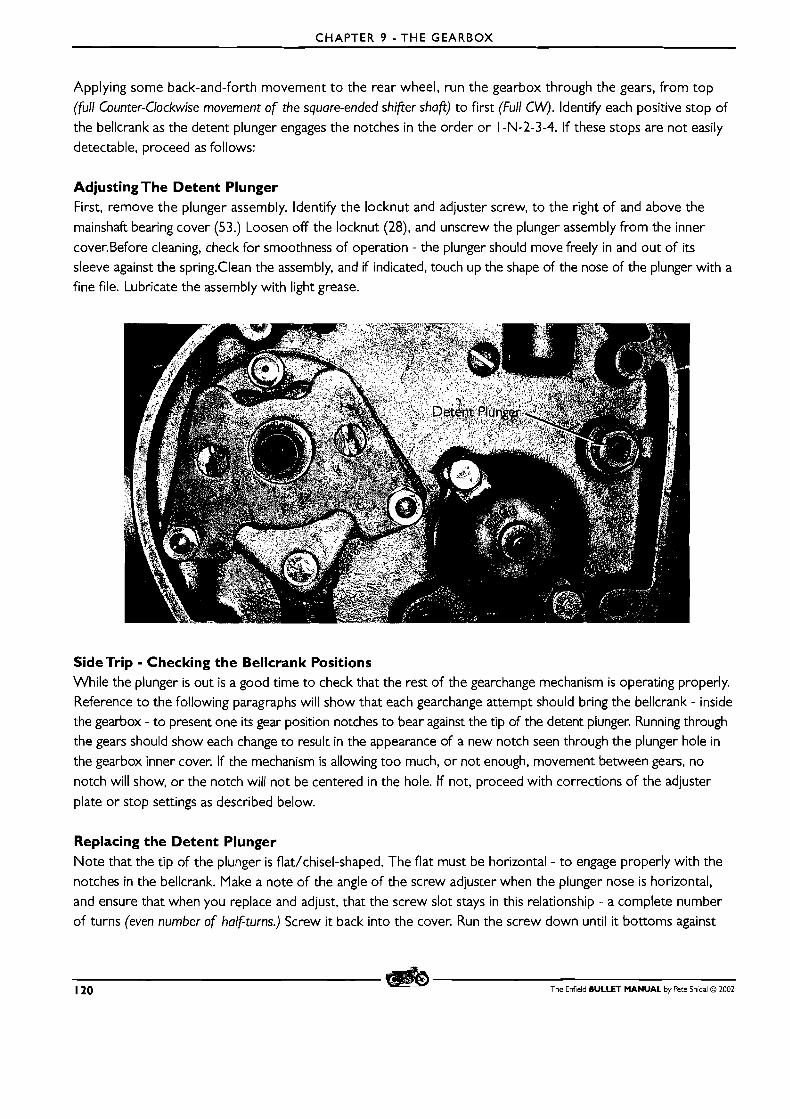
CHAPTER 9 - THE GEARBOX
Applying some back-and-forth movement t o the rear wheel, run the gearbox through the gears, from top
(full Counter-Clockwise movement of the square-ended shifier shafi) to first (Full CW). Identify each positive stop of
the bellcrank as the detent plunger engages the notches in the order or 1 -N-2-3-4. If these stops are not easily
detectable, proceed as follows:
Adjusting The Detent Plunger First, remove the plunger assembly. ldentify the locknut and adjuster screw, to the right of and above the
mainshaft bearing cover (53.) Loosen off the locknut (28), and unscrew the plunger assembly from the inner
cover.Before cleaning, check for smoothness of operation - the plunger should move freely in and out of its
sleeve against the spring.Clean the assembly, and if indicated, touch up the shape of the nose of the plunger with a fine file. Lubricate the assembly with light grease.
SideTrip - Checking the Bellcrank Positions While the plunger is out is a good time to check that the rest of the gearchange mechanism is operating properly. Reference t o the following paragraphs will show that each gearchange attempt should bring the bellcrank - inside the gearbox - to present one its gear position notches to bear against the tip of the detent plunger. Running through the gears should show each change t o result in the appearance of a new notch seen through the plunger hole in
the gearbox inner cover. If the mechanism is allowing too much, or not enough, movement between gears, no
notch will show, or the notch will not be centered in the hole. If not, proceed with corrections of the adjuster
plate or stop settings as described below.
Replacing the Detent Plunger Note that the tip of the plunger is flat/chisel-shaped. The flat must be horizontal - to engage properly with the
notches in the bellcrank. Make a note of the angle of the screw adjuster when the plunger nose is horizontal, and ensure that when you replace and adjust, that the screw slot stays in this relationship - a complete number of turns (even number of halfturns.) Screw it back into the cover. Run the screw down until it bottoms against
120 The Enfield BULLET MANUAL by Pete Snidal O 2002
CHAPTER 9 - THE GEARBOX
the spring, then back it off to reasonable tension - maintaining the point angle as detailed above. Test the tension by running the gearbox back and forth through the gears as detailed above. When satisfactory action has been
attained, holding the screw with a suitable screw driver, tighten the locknut.
Experiment with plunger tension until if feels best - not too tight to hinder shifting, nor loose enough to allow
the gearbox to slip out of a gear once chosen.
Once you have worked the gearbox through the gears a few times, and are feeling positive "stops" between them
as the detent plunger engages the appropriate notch in the shifter bellcrank, reassemble and road-test. This procedure
will correct the vast percentage of shifting problems. If shifting difficulty is still experienced with the detent plunger working properly, the problem can only be the linkage moving too far, or not far enough. For example, if difficulty
is experienced getting into top gear from third, the linkage is not moving far enough in the upshift direction. If it consistently fails to get past Neutral from second, the difficulty is lack of sufficient movement in the downshift direction. Note also that not enough movement in one direction is often accompanied by too much movement in the other. For example, if insufficient downshift movement is experienced (missing first from 2nd), excessive upshift movement may make for attempts at 3rd from 2nd going past 3rd into the 3-4 "false neutral." To correct shifting problems once satisfied with the detent plunger, see the section on ratchet adjusting.
2.The Shifter Adjustment Plate (56) Rotation of the Outer Ratchet Ring (63) (see illustration on page 114) imparts rotation to the inner ratchet
(66), which is passed on via the bellcrank actuator (46), and the bellcrank to the sliding gears to effect gearchanges. Each movement of the gearshift lever, up or down, must be met with engagement of the ratchet
teeth in a balanced way - ie, there must be about the same amount of movementjn either direction, by the time the teeth engage.
If there is too much outer ring movement before engagement, in either direction, completeness of the
gearchange will suffer; the inner ratchet will not move far enough by the time the shifter assy. has reached its
stop for the bellcrank to have reached the next gear. Such imbalance is corrected by rotating the shifter plate
(57) on i ts slots, through which it is bolted to the outside of the inner gearbox cover by the pillar studs, which also hold the whole assembly together. The position of the Shifter Adjuster Plate determines where the outer ratchet ring will center after each movement of the foot gearchange lever.
To adjust plate position, first the outer nuts holding the stop plate (67) must be loosened, to allow turning of the pillar studs. Once this is done, it will be seen that each of the two studs has a hexagonal (or bi-flat) portion
outside of the shifter plate (57). Loosening these studs slightly will allow rotation of the shifter plate, which will
change the centering of the outer ratchet mechanism between gear changes.
You may be able to attain good balance referencing the engagement of the ratchet teeth through the holes provided
in the stop plate (67.) The curious may elect to remove the stop plate temporarily, which will give a more total view of the action of the ratchet parts. The overview section on gearshifting shows photos of the ideal settings.
With the machine on the center stand, rotate the wheel back and forth as you change gears up and down throughout the range. Find the best position of the adjuster plate for even engagement of the ratchet teeth in either direction.
The Enfield BULLET MANUAL by Pete Snidal D ZOO2 12 1
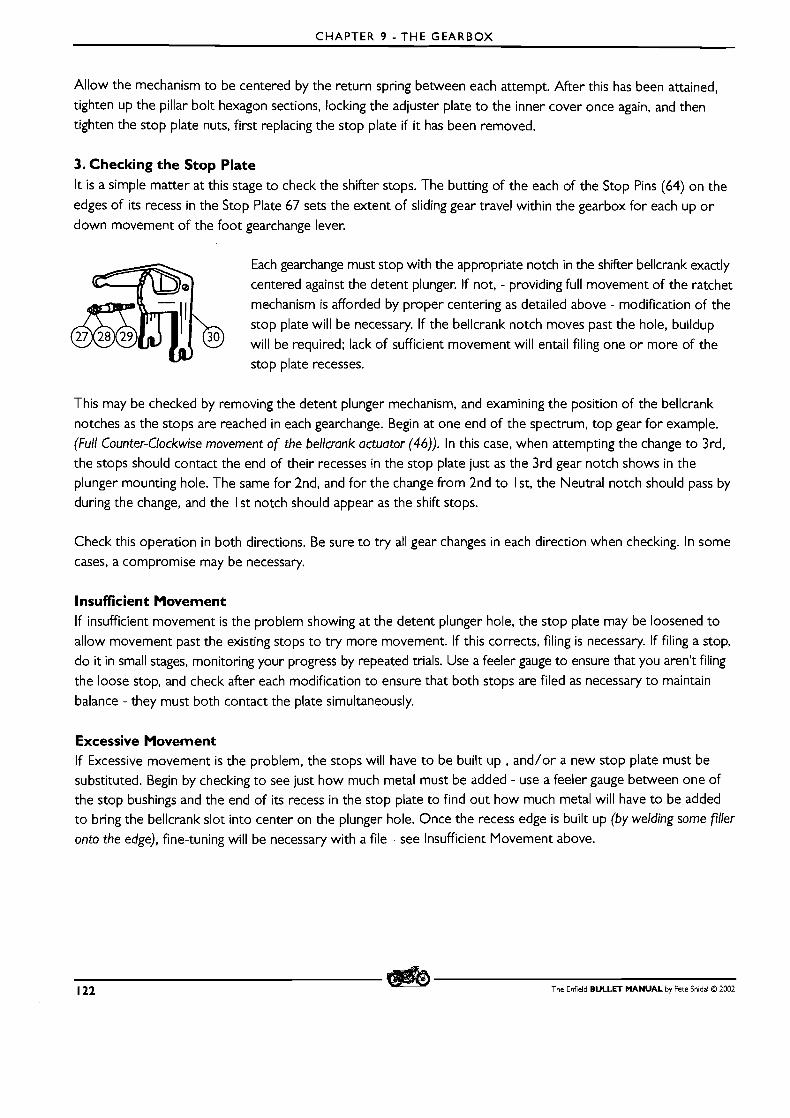
CHAPTER 9 - THE GEARBOX
Allow the mechanism to be centered by the return spring between each attempt. After this has been attained,
tighten up the pillar bolt hexagon sections, locking the adjuster plate to the inner cover once again, and then
tighten the stop plate nuts, first replacing the stop plate if it has been removed.
3. Checking the Stop Plate I t is a simple matter at this stage to check the shifter stops. The butting of the each of the Stop Pins (64) on the
edges of i ts recess in the Stop Plate 67 sets the extent of sliding gear travel within the gearbox for each up o r
down movement of the foot gearchange lever.
Each gearchange must stop with the appropriate notch in the shifter bellcrank exactly
centered against the detent plunger. If not, - providing full movement of the ratchet
mechanism is afforded by proper centering as detailed above - modification of the
stop plate will be necessary. If the bellcrank notch moves past the hole, buildup
will be required; lack of sufficient movement will entail filing one or more of the
stop plate recesses.
This may be checked by removing the detent plunger mechanism, and examining the position of the bellcrank
notches as the stops are reached in each gearchange. Begin at one end of the spectrum, top gear for example.
(Full Counter-Clockwise movement of the bellcrank actuator (46)). In this case, when attempting the change to 3rd, the stops should contact the end of their recesses in the stop plate just as the 3rd gear notch shows in the
plunger mounting hole. The same for 2nd, and for the change from 2nd to I st, the Neutral notch should pass by
during the change, and the I s t notch should appear as the shift stops.
Check this operation in both directions. Be sure to try all gear changes in each direction when checking. In some
cases, a compromise may be necessary.
Insufficient Movement If insufficient movement is the problem showing at the detent plunger hole, the stop plate may be loosened to
allow movement past the existing stops to try more movement. If this corrects, filing is necessary. If filing a stop,
do it in small stages, monitoring your progress by repeated trials. Use a feeler gauge to ensure that you aren't filing
the loose stop, and check after each modification to ensure that both stops are filed as necessary to maintain
balance - they must both contact the plate simultaneously.
Excessive Movement If Excessive movement is the problem, the stops will have to be built up , and/or a new stop plate must be
substituted. Begin by checking to see just how much metal must be added - use a feeler gauge between one of the stop bushings and the end of its recess in the stop plate to find out how much metal will have to be added to bring the bellcrank slot into center on the plunger hole. Once the recess edge is built up (by welding some filler
onto the edge), fine-tuning will be necessary with a file - see Insufficient Movement above.
122 The Enfield BULLET MANUAL by Pete Snidal O 2002
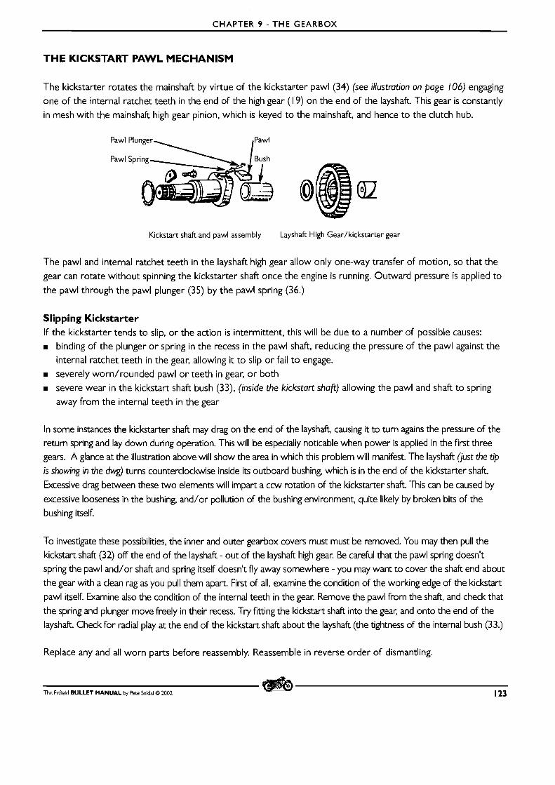
CHAPTER 9 - THE GEARBOX
THE KICKSTART PAWL MECHANISM
The kickstarter rotates the mainshaft by virtue of the kickstarter pawl (34) (see illustration on page 106) engaging
one of the internal ratchet teeth in the end of the high gear ( l 9) on the end of the layshaft. This gear is constantly
in mesh with the mainshaft high gear pinion, which is keyed to the mainshaft, and hence to the clutch hub.
Kickstart shaft and pawl assembly Layshaft High Gear/kickstarter gear
The pawl and internal ratchet teeth in the layshaft high gear allow only one-way transfer of motion, so that the
gear can rotate without spinning the kickstarter shaft once the engine is running. Outward pressure is applied to
the pawl through the pawl plunger (35) by the pawl spring (36.)
Slipping Kickstarter If the kickstarter tends to slip, or the action is intermittent, this will be due to a number of possible causes: m binding of the plunger or spring in the recess in the pawl shaft, reducing the pressure of the pawl against the
internal ratchet teeth in the gear, allowing it to slip or fail t o engage.
m severely worn/rounded pawl or teeth in gear, or both
m severe wear in the kickstart shaft bush (33), (inside the kickstart shafi) allowing the pawl and shaft to spring
away from the internal teeth in the gear
In some instances the kickstarter shaft may drag on the end of the layshaft, causing it to turn agains the pressure of the return spring and lay down during operation. This will be especially noticable when power is applied in the first three
gears. A glance at the illustration above will show the area in which this problem will manifest. The layshaft (just the tip
is showing in the dwg) turns counterclockwise inside its outboard bushing, which is in the end of the kickstarter shaft.
Excessive drag between these two elements will impart a ccw rotation of the kickstarter shaft. This can be caused by
excessive looseness in the bushing, and/or pollution of the bushing environment, quite likely by broken bits of the
bushing itself.
To investigate these possibilities, the inner and outer gearbox covers must must be removed. You may then pull the
kickstart shaft (32) off the end of the layshaft - out of the layshaft high gear. Be careful that the pawl spring doesn't spring the pawl and/or shaft and spring itself doesn't fly away somewhere - you may want to cover the shaft end about
the gear with a clean rag as you pull them apart. First of all, examine the condition of the working edge of the kickstart
pawl itself. Examine also the condition of the internal teeth in the gear. Remove the pawl from the shaft, and check that
the spring and plunger move freely in their recess. Try fitting the kickstart shaft into the gear, and onto the end of the
layshaft. Check for radial play at the end of the kickstart shaft about the layshaft (the tightness of the internal bush (33.)
Replace any and all worn parts before reassembly. Reassemble in reverse order of dismantling.
The Enfield BULLET MANUAL by Pete Snidal O 2002 123
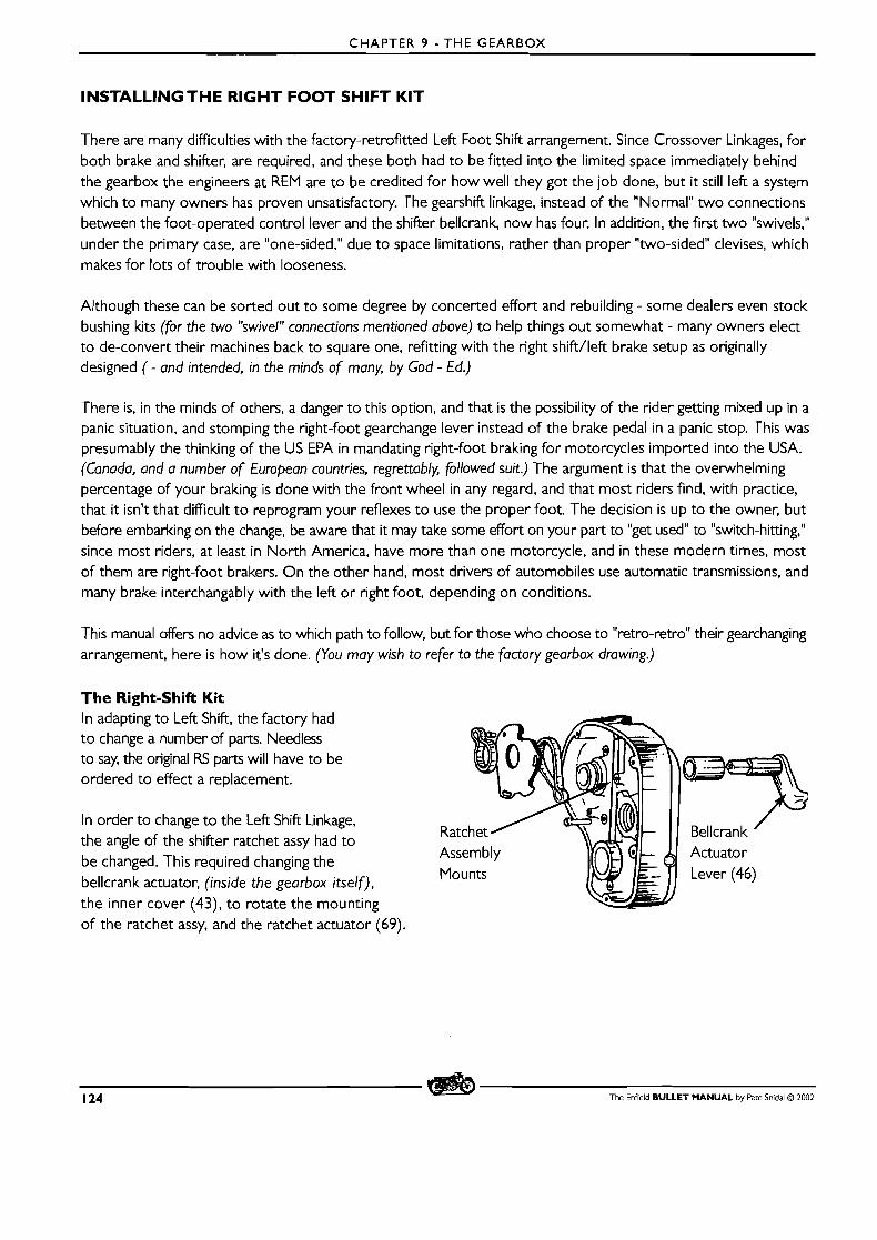
CHAPTER 9 - THE GEARBOX
INSTALLING THE RIGHT FOOT SHIFT KIT
'There are many difficulties with the factory-retrofitted Left Foot Shift arrangement. Since Crossover Linkages, for both brake and shifter, are required, and these both had to be fitted into the limited space immediately behind the gearbox the engineers at REM are to be credited for how well they got the job done, but it still left a system which to many owners has proven unsatisfactory. The gearshift linkage, instead of the "Normal" two connections between the foot-operated control lever and the shifter bellcrank, now has four. In addition, the first two "swivels," under the primary case, are "one-sided," due to space limitations, rather than proper "two-sided" devises, which makes for lots of trouble with looseness.
Although these can be sorted out to some degree by concerted effort and rebuilding - some dealers even stock bushing kits (for the two swivel" connections mentioned above) to help things out somewhat - many owners elect to de-convert their machines back to square one, refitting with the right shift/left brake setup as originally designed ( - and intended, in the minds of many, by God - Ed.)
There is, in the minds of others, a danger to this option, and that is the possibility of the rider getting mixed up in a panic situation, and stomping the right-foot gearchange lever instead of the brake pedal in a panic stop. This was presumably the thinking of the US EPA in mandating right-foot braking for motorcycles imported into the USA. (Canada, and a number of European countries, regrettably, followed suit.) The argument is that the overwhelming percentage of your braking is done with the front wheel in any regard, and that most riders find, with practice, that it isn't that difficult to reprogram your reflexes to use the proper foot. The decision is up to the owner, but before embarking on the change, be aware that it may take some effort on your part to "get used" to "switch-hitting," since most riders, at least in North America, have more than one motorcycle, and in these modern times, most of them are right-foot brakers. O n the other hand, most drivers of automobiles use automatic transmissions, and many brake interchangably with the left or right foot, depending on conditions.
This manual offers no advice as to which path to follow, but for those who choose to "retro-retro" their gearchanging arrangement, here is how it's done. (You may wish to refer to the factory gearbox drawing.)
The Right-Shift Kit In adapting to Left Shift, the factory had to change a number of parts. Needless to say, the original RS parts will have to be ordered to effect a replacement.
In order to change to the Left Shift Linkage, the angle of the shifter ratchet assy had to be changed. This required changing the bellcrank actuator, (inside the gearbox itself), the inner cover (43), to rotate the mounting of the ratchet assy, and the ratchet actuator (69).
Mounts
124 The Enfield BULLET MANUAL by Pete Snidai O 2002
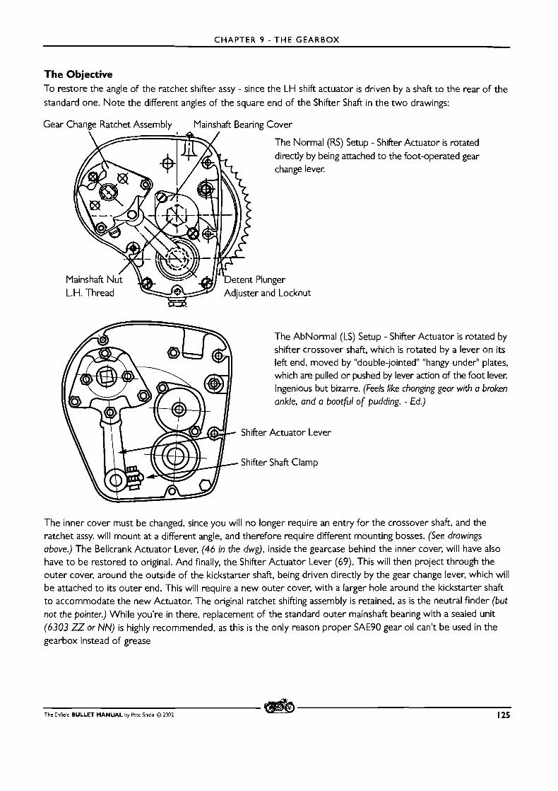
CHAPTER 9 - THE GEARBOX
The Objective To restore the angle of the ratchet shifter assy - since the LH shift actuator is driven by a shaft to the rear of the
standard one. Note the different angles of the square end of the Shifter Shaft in the two drawings:
Gear ,ssembly Mainshaft Bearing Cover Change Ratchet A
The Normal (RS) Setup - directly by being attached change lever.
' ~e ten t Plunger Adjuster and Locknut
Shifter to the
Actuator is rotated foot-operated gear
The AbNormal (LS) Setup - Shifter Actuator is rotated by shifter crossover shaft, which is rotated by a lever on i ts left end, moved by "double-jointed" "hangy-under" plates, which are pulled or pushed by lever action of the foot lever. Ingenious but bizarre. (feels like changing gear with a broken ankle, and a bootfil of pudding. - €d.)
Shifter Actuator Lever
Shifter Shaft Clamp
The inner cover must be changed, since you will no longer require an entry for the crossover shaft, and the ratchet assy. will mount at a different angle, and therefore require different mounting bosses. (See drawings above.) The Bellcrank Actuator Lever, (46 in the dwg), inside the gearcase behind the inner cover, will have also have to be restored to original. And finally, the Shifter Actuator Lever (69). This will then project through the outer cover, around the outside of the kickstarter shaft, being driven directly by the gear change lever, which will be attached to its outer end. This will require a new outer cover, with a larger hole around the kickstarter shaft to accommodate the new Actuator. The original ratchet shifting assembly is retained, as is the neutral finder (but not the pointer.) While you're in there, replacement of the standard outer mainshaft bearing with a sealed unit (6303 ZZ or NN) is highly recommended, as this is the only reason proper SAE9O gear oil can't be used in the gearbox instead of grease
The Enfield BULLET MANUAL by Pete Snidal O 2002 125
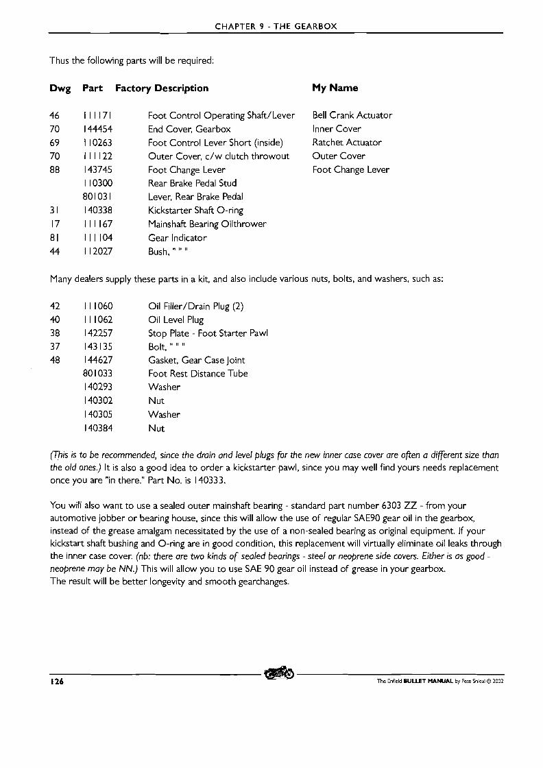
CHAPTER 9 - THE GEARBOX
Thus the following parts will be required:
Dwg Part Factory Description My Name
Foot Control Operating Shaft/Lever Bell Crank Actuator
End Cover, Gearbox Inner Cover Foot Control Lever Short (inside) Ratchet Actuator
Outer Cover, c/w clutch throwout Outer Cover
Foot Change Lever Foot Change Lever
Rear Brake Pedal Stud Lever, Rear Brake Pedal
Kickstarter Shaft 0-ring Mainshaft Bearing Oilthrower
Gear Indicator
Bush, " " "
Many dealers supply these parts in a kit, and also include various nuts, bolts, and washers, such as:
Oil Filler/Drain Plug (2)
Oil Level Plug Stop Plate - Foot Starter Pawl
Bolt, " " " Gasket, Gear Case Joint Foot Rest Distance Tube Washer
Nut
Washer
Nut
(This is to be recommended, since the drain and level plugs for the new inner case cover are ojten a different size than the old ones.) It is also a good idea to order a kickstarter pawl, since you may well find yours needs replacement once you are "in there." Part No. is 140333.
You will also want to use a sealed outer mainshaft bearing - standard part number 6303 ZZ - from your automotive jobber or bearing house, since this will allow the use of regular SAE9O gear oil in the gearbox, instead of the grease amalgam necessitated by the use of a non-sealed bearing as original equipment. If your kickstart shaft bushing and 0-ring are in good condition, this replacement will virtually eliminate oil leaks through the inner case cover. (nb: there are two kinds of sealed bearings - steel or neoprene side covers. Either is as good - neoprene may be NN.) This will allow you to use SAE 90 gear oil instead of grease in your gearbox. The result will be better longevity and smooth gearchanges.
126 The Enfield BULLET MANUAL by Pete Snidal O 2002
CHAPTER 9 -THE GEARBOX
Should You or ShouldnltYou? I should begin by saying this is not a project for the mechanically light of heart. It will consist of:
W I . Removal of the brake and shifter crossover shafts behind the gearbox, as well as the various intermediate
and operating levers and linkages. (about I hr.) Re & re (removal and replacement) of the outer cover, the entire ratchet shifter assembly, the inner cover,
and the Bellcrank Actuator Lever. (min. 3 hours)
Pressing the new Actuator Shaft bushing, and the new sealed bearing in to the inner cover. (about I hour)
m Setting up the ratchet shifter assembly from square one. (from I to many hours.) Learning to ride a RS motorcycle - and remembering you're on one when you switch from a (these days)
"conventional" LS model - or your Right-Brake auto or truck. (the rest of your riding career!)
A full weekend should be scheduled for the job. First-time, it can easily take two fairly full days. The advantages gained will be:
Removal of a number of "middle men" in the shifter linkage - from 6 moving parts pivots to I - giving a much
more positive shifting action.
W Allowing the gearbox to run straight SAE9O gear lube instead of grease or a grease mixture - smoother
operation and gear changing, as well as better bearing, bushing, and gear lubrication (Provided the 6303 ZZ bearing is installed with the job)
m A more period look and feel to the living dinosaur that is your motorcycle m If you have other "old Brits," an elimination of the need to "switch hit" between them
m A chance to "really get in there" and do some serious nuts-and-bolts work on your Living Meccano Set
The Procedure First, ensure that all the necessary parts are there. Check the parts you have against the list on the previous page. When you are ready, begin:
Slacken off the rear brake adjuster at the wheel end.
W Disconnect the linkage spring from the stoplight switch. Ensure that the delicate switch will be safe,
and disconnect the front of the brake linkage rod from the lever at the end of the crossover shaft. Then:
I. Remove the outer gearbox cover. Unscrew and remove the Shifter Shaft Clamp Screw and tap in a flat
screwdriver blade to spread the clamp.
2. Remove the Stop Plate (67) - the first one of the Shifter Ratchet Assembly.
3. You will now be able to remove the shifter actuator lever, and the rest of the Shifter Ratchet Assembly
(58 - 66). You will likely have to remove the actuator lever clamp bolt completely, and then spread the
clevis slightly with a slot-blade screwdriver as you withdraw the lever and inner ratchet assy all at once.
Then unscrew the two pillar screws (65), and remove the Adjuster plate (57 and spring (56). Remove also
the circlip on the shifter crossover shaft - it will be found nestled in a greasy mess against the inner face of
the inner case.
4. Remove the inner cover. (See page 1 12)
The Enfield BULLET MANUAL by Pete Snidal O 2002 127
CHAPTER 9 - THE GEARBOX
Hot Tip: One of the 5 inner case cover screws is a countersunk flathead - head flush with the greasy case surface. They used a flathead for clearance behind the shifter assy. Be sure to find this under the grease and remove it with the other 4 screws.
Another Hot Tip: When the inner cover (43) is removed, leave the LS bellcrank actuator (46) in it and set it aside. You D O NOT want inadvertently to reinstall the wrong lever!
5. Remove the Right-foot brake pedal and crossover shaft. - There are clamps on the levers at each end, and
circlip(s) on the shaft, inside the mounting lugs on the frame, as well. Use the old screwdriver trick to spread the clamps as you remove the levers. D o the same for the LS gearchange linkage and crossover shaft. Check
carefully for circlips on the shaft.
6. Prepare your new RS inner cover for assembly. This will entail transferring over your old Kickstarter Stop Plate, if necessary, and pressing in your new shifter actuator bushing and outer mainshaft bearing. If no press is available, you may use a threaded rod and nutdwashers, with wrench/spanner sockets for mandrels.
Ensure that bearing and bushing are presented and pressed squarely to the cover. I t is a good idea to "test
fly" your pressing arrangements before heating the cases and doing the actual pressing.
Hot Tip : The actuator shaft bushing will likely be tapered on one end - this is to help with pressing it in. It wants to be flush with the REAR (gearbox side) of the inner cover - it also acts as a bearing for the shifter plate on the outside, and must project enough to do this. If it is tapered, ensure that the taper is fitted to the inside, ie press it through taper- first from the outside.
A t this time, press the new sealed 6303 ZZ sealed main bearing into the case as well. Heat the cover t o "spitting hot" before pressing in the bushing and bearing.
Gearbox Vent: As shipped, the Bullet has no venting for the gearbox. This is a good time to drill a small hole 13/64" - 2mm into the outside of the Filler Passage - the bump on the outside of the cover just below the filler hole - so that any buildup of foam o r gasses will dissipate into the unsealed cavity between the covers. Hole should be about 1 /4" - 6mm distance from the underside of the top face of the cover.
7. Side Trip - examining the kickstarter parts: Carefully draw the kickstarter shaft (32) out of the inner cover.
(1 9). Hold the spring-loaded plunger down with a small flat-blade screwdriver, and withdraw the pawl (34) out of the shaft. Be careful not to let the plunger go, so as to avoid surprises with spring ejection. Once the
pawl is clear, let the spring pressure off slowly.
Examine the kickstarter parts. Check that the pawl (34) has good sharp corners on the face which engages the kickstarter gear (1 9), and that the inner teeth in the gear itself (down there in the layshafl) are still well-cornered. If not, this is a good time to make any necessary replacements. Check that the pawl moves freely in and out in the bore, and that there is noticable spring tension. Check the condition of the Layshaft kshing (33) in the inside of the kickstarter shaft by attempting to rock it radially on the layshaft. If there is noticable slop, you may elect to replace the kickstarter shaft, or have the bushing replaced. Check the condition of the kickstarter shaft 0-ring (3 1). Replace if necessary.
128 The Enfield BULLET MANUAL by Pete Snidal O 2002

CHAPTER 9 - THE GEARBOX
9. Fit the new bellcrank actuator lever (46) into the inside of the cover. Be sure that you have not confused the old and new (LS and RS) actuator levers!
8. Reassemble the kickstarter shaft/spring/plunger/pawl assembly into the new inner case. Grease the shaft
and bushing before re-introducing. There should be some slight tightness due to the 0-ring on the kicker
shaft. Ensure that the thrust washer (1 8) is on the Layshaft.
10. Carefully clean the gasket faces on case and cover. Using a new gasket, with sealer applied to both faces,
introduce the cover to the gearbox. Rotate the Bellcrank Actuator (46) so that it engages i ts operating tab
on the bellcrank as you present the cover to the gearcase - using a light, look into the opening and ensure
that it engages the bellcrank properly. You will find it easier to push the actuator shaft into the case an inch
o r so before presenting cover to case.
There is a projecting ridge at the bottom of the gearcase, which fits into a corresponding recess in the bottom of the inner cover. Be careful that the gasket does not get pinched here, and sheared by the action of being in the wrong place as the case cover is tightened.
You will probably have to tap the mainshaft bearing onto the shaft - use a large socket as a mandrel - as you pull the cover onto the case with the mounting screws. Do not use too much torque on the screws! (Stripping the threads in the case could be disastrous!) Use light taps only - little force should be required. If it doesn't go, take it off again and find out why.
I I. Replace all inner cover holding screws. There may be a countersink-style screw from the old setup, but
no countersink in the new cover. Use a regular screw for replacement - standard 1 /4-20 should fit. In a
pinch, you may use the old countersunk screw.
Mainshaft End Play: Before fitting the Outer Bearing Nut, ensure that some endplay is present on the mainshaft - the position of the bearing may have changed with the new cover, and this could be too far to the left, resulting in no endplay at all, o r too far to the right, see below. If no endplay is present, you may have to use two gaskets in the joint, o r in extreme cases, or a sincere desire to do it right, re & re the new bearing, shimming the end of the bearing recess before installing.
12. Re-fit the Mainshaft Outer Bearing nut. Left Hand Thread! Torque is 35 - 50 Ft-Lbs. Find a gear by rotating
the Square Bellcrank Actuator Shaft, and have someone apply rear brake to keep the shaft from turning as
you torque it. Bend the tab washer over to lock - if the metal isn't too springy to bend. If you have used a sealed bearing, the old oil slinger washer is now only necessary as a spacer.
Once the nut is tightened, pulling the mainshaft tightly against the inner side of the bearing, the position of the shaft, and therefore of the clutch, is set by the position of the outer main bearing. Changing the case may have altered this position. In extreme cases, the shaft may have been moved too far to the right for sufficient clearance between the clutch hub and the inner primary case. This will result in serious noise when the clutch is rotated. Test it now by putting the gearbox back in neutral, and spinning the engine with the kickstarter, using decom- pressor, or better still by removing the spark plug, and listening for any knocking or banging from the area of the rear inner chaincase. (You will have to replace the kickstarter on the open shafi temporarily.)
The Enfield BULLET MANUAL by Pete Snidal O 2002 129
CHAPTER 9 - THE GEARBOX
If such knocking is heard, you'll have to go back and remove the inner cover, and place .025"/.6mm of shim washer(s) on the mainshaft between the inner oil slinger and the bearing. After re-fitting the inner cover and tightening the mainshaft nut, retest and shim more if necessary.
13. Re-fit the bearing cover, and the kickstarter spring. Pre-tension the kickstarter spring, and hold the
anchored end in place with pliers as you fit and tighten the mounting screw it shares with the mainbearing
cover - avoid radial thrust on the screw until it's in tight. Be careful not to cross-thread the screw - it must
go in straight. Be sure to put the clutch throwout rod back into the mainshaft.
14. Refit and and adjust the detent plunger
15. Re-fit the Adjuster Plate and spring (57, 56.) Fit the pillar studs, (65) with their washers, to hold it in
place -leave the adjustment at the mid-point of the slots to start with. just "snug up1' the studs -
you'll be back!
16. Refit the Outer Ratchet Plate Assy. (62,3) to the Adjuster Plate. Ensure that the shifter shaft bushing in
the inner case cover projects through the large hole in the center of the first plate. Grease the area
around the hole, as the plate rotates about this bushing.
17. Fit the inner ratchet (67) onto the square shifter shaft (46.)
18. Now it is time to play with the shifter ratchet adjustment. Read the section on the Ratchet Shifter Assembly.
You may wish to read and review the entire section on shifter adjustment.
19. Once the shifter mechanism is performing as properly as you can get it, it is time to test it on the road.
Replace the outer cover. You will find that it helps to grasp the clutch cable nipple through the top
inspection hole of the cover, and work it into place in the throwout lever as you put the cover in place.
N o gasket sealer is required.
20. Fit the neutral finder parts, the kickstarter, and your new gearchange lever. Fit the clutch cable and
adjust the clutch. Remove the filler and level plugs (42, 39) and top up the gearbox with SAE9O gear oil.
2 1 . Fit the new brake lever mounting/fulcrum bolt into the presently-unused threaded lug on the frame
behind the chaincase.
22. Fit the new brake lever connect the linkage rod. Be careful to replace the cotter pin holding the rod in the brake lever.
23. Reconnect the brake light switch spring to the linkage rod. Adjust the rear brake Test to see that the brake light works. Adjust as necessary.
24. Before test riding, carefully review your "Stop Reflex" and gear changing strategies, remembering that
you've just changed feet!
25. Take the machine off the workstand, if applicable.
130 The Enfield BULLET MANUAL by Pete Snidal O 2002
CHAPTER 9 - THE GEARBOX
26. Si t on the machine, rock it back and forth as you go through selecting the various gears with the lever.
Check the gear indicator and see that proper gear engagement is occurring. If this checks out to this stage,
start the machine and test-ride. REMEMBER YOUR BRAKE IS N O W O N THE LEFT!
Switch-Hitter's Hint: Every time I start a motorcycle, I try to remember to do a couple of little "practice stops" as I start off. I don't come back to a full stop; just apply a little rear brake and shut of the throttle a bit, so as to "re-programme" my brain, hopefully, for the particular machine I've just climbed onto. This is a good habit to get into EVERY time you start a motorcycle, in the world of "switch-hit" shifting.
27. If further shifter adjustment is required, review the steps above and work at it until it's correct. You are now a Bullet Mechanic!
The Enfield BULLET MANUAL by Pete Snidal 63 2002 13 1
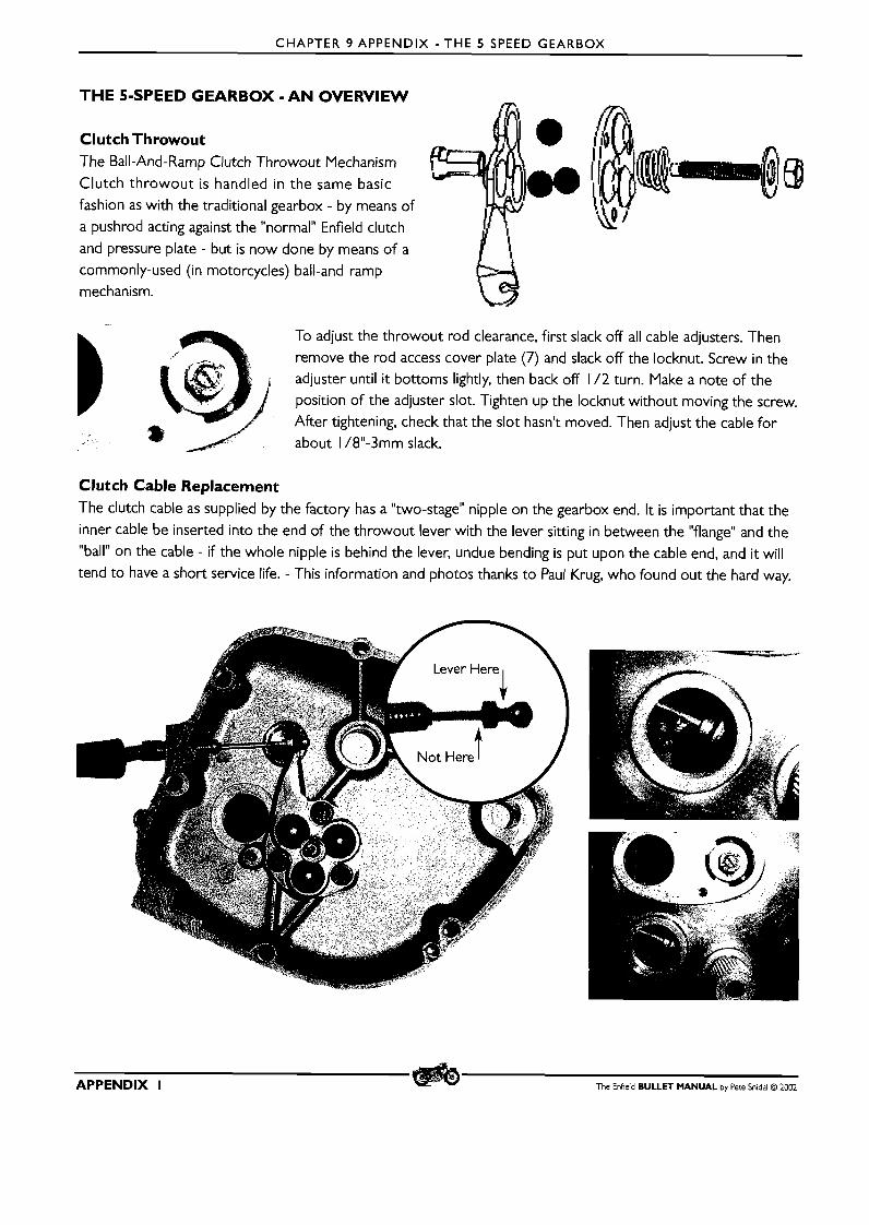
CHAPTER 9 APPENDIX - THE 5 SPEED GEARBOX
THE 5-SPEED GEARBOX - A N OVERVIEW
Clutch Throwout The Ball-And-Ramp Clutch Throwout Mechanism
Clutch throwout is handled in the same basic fashion as with the traditional gearbox - by means of
a pushrod acting against the "normal" Enfield clutch
and pressure plate - but is now done by means o f a
commonly-used (in motorcycles) ball-and-ramp mechanism.
To adjust the throwout rod clearance, first slack off all cable adjusters. Then
remove the rod access cover plate (7) and slack off the locknut. Screw in the adjuster until it bottoms lightly, then back off 1 /2 turn. Make a note of the
position of the adjuster slot. Tighten up the locknut without moving the screw. After tightening, check that the slot hasn't moved. Then adjust the cable for
about 1 /8"-3mm slack.
Clutch Cable Replacement The clutch cable as supplied by the factory has a "two-stage" nipple on the gearbox end. It is important that the
inner cable be inserted into the end of the throwout lever with the lever sitting in between the "flange" and the
"ball" on the cable - if the whole nipple is behind the lever, undue bending is put upon the cable end, and it will
tend to have a short service life. - This information and photos thanks to Paul Krug, who found out the hard way.
APPENDIX I The Enfield BULLET MANUAL by Pete Snidal O 2002
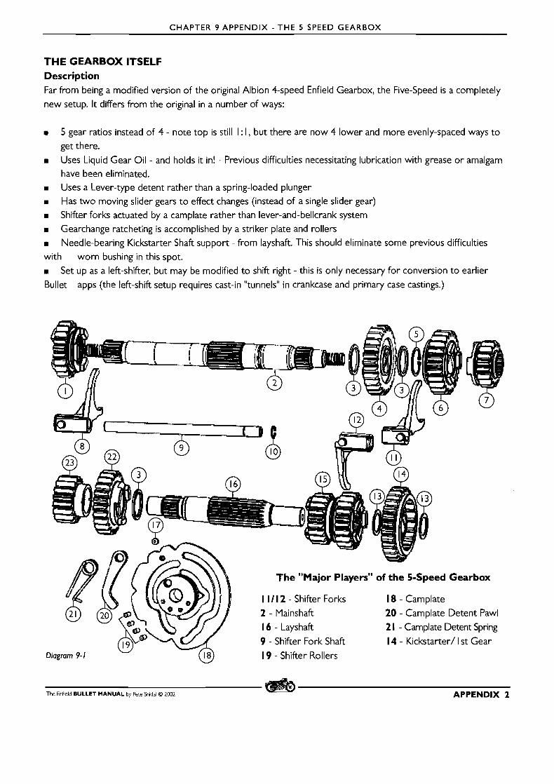
CHAPTER 9 APPENDIX - THE 5 SPEED GEARBOX
T H E GEARBOX ITSELF Description Far from being a modified version of the original Albion 4-speed Enfield Gearbox, the Five-Speed is a completely new setup. It differs from the original in a number of ways:
m 5 gear ratios instead of 4 - note top is still I : I, but there are now 4 lower and more evenly-spaced ways to get there.
m Uses Liquid Gear Oil - and holds it in! - Previous difficulties necessitating lubrication with grease or amalgam have been eliminated.
m Uses a Lever-type detent rather than a spring-loaded plunger m Has two moving slider gears to effect changes (instead of a single slider gear) m Shifter forks actuated by a camplate rather than lever-and-bellcrank system m Gearchange ratcheting is accomplished by a striker plate and rollers m Needle-bearing Kickstarter Shaft support - from layshaft. This should eliminate some previous difficulties with worn bushing in this spot. m Set up as a left-shifter, but may be modified to shift right - this is only necessary for conversion to earlier Bullet apps (the left-shift setup requires cast-in "tunnels" in crankcase and primary case castings.)
The Enfield BULLET MANUAL by Pete Snidal O 2002 APPENDIX 2
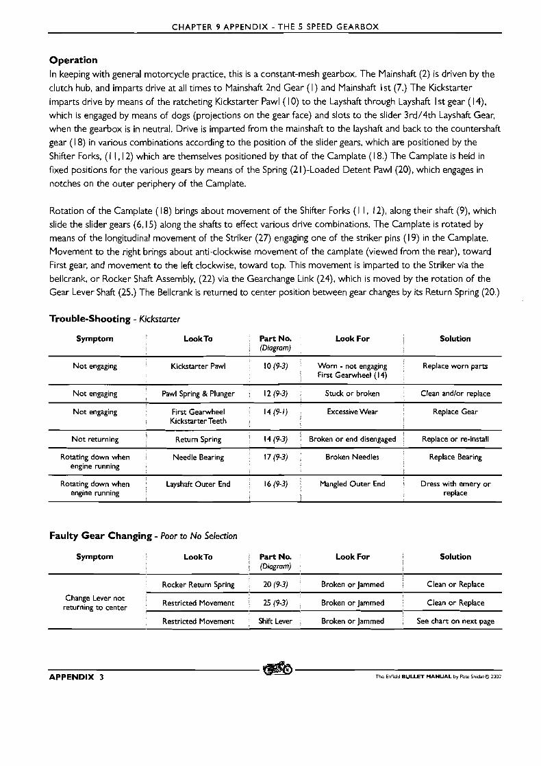
CHAPTER 9 APPENDIX - THE 5 SPEED GEARBOX
Operation In keeping with general motorcycle practice, this is a constant-mesh gearbox. The Mainshaft (2) is driven by the
clutch hub, and imparts drive at all times to Mainshaft 2nd Gear ( I ) and Mainshaft 1st (7.) The Kickstarter
imparts drive by means of the ratcheting Kickstarter Pawl ( 10) to the Layshaft through Layshaft I st gear ( 1 4),
which is engaged by means of dogs (projections on the gear face) and slots to the slider 3rd/4th Layshaft Gear,
when the gearbox is in neutral. Drive is imparted from the mainshaft to the layshaft and back to the countershaft
gear ( 1 8) in various combinations according to the position of the slider gears, which are positioned by the
Shifter Forks, ( 1 1,12) which are themselves positioned by that of the Camplate ( 1 8.) The Camplate is held in
fixed positions for the various gears by means of the Spring (2 1)-Loaded Detent Pawl (20), which engages in
notches on the outer periphery of the Camplate.
Rotation of the Camplate (1 8) brings about movement of the Shifter Forks ( I 1 , 12), along their shaft (9), which
slide the slider gears (6,15) along the shafts to effect various drive combinations. The Camplate is rotated by
means of the longitudinal movement of the Striker (27) engaging one of the striker pins ( 1 9) in the Camplate.
Movement to the right brings about anti-clockwise movement of the camplate (viewed from the rear), toward
First gear, and movement to the left clockwise, toward top. This movement is imparted to the Striker via the
bellcrank, o r Rocker Shaft Assembly, (22) via the Gearchange Link (24), which is moved by the rotation of the Gear Lever Shaft (25.) The Bellcrank is returned to center position between gear changes by its Return Spring (20.)
Trouble-Shooting - Kickstarter
Symptom Look To Part No. Look For I Solution (Diagram)
Not engaging Kickstarter Pawl 1 0 (9-3) Worn - not engaging Replace worn parts First Gearwheel (14)
Not engaging Pawl Spring & Plunger . 12 (9-3) Stuck or broken Clean andlor replace
First Gearwheel Excessive Wear Kickstarter Teeth
engine running
Rotating down when Layshaft Outer End 1 6 (9-3) Mangled Outer End 4 Dress with emery or engine running replace
I i
Faulty Gear Changing - Poor to No Selection
Symptom Look To Part No. Look For i
Solution (Diagram) i
Rocker Return Spring 20 (9-3) Broken or Jammed a Clean or Replace
Change Lever not ' Restricted Movement 25 (9-3) Broken or Jammed Clean or Replace returning to center
Restricted Movement , Shift Lever Broken or Jammed See chart on next page
APPENDIX 3 The Enfield BULLET MANUAL by Pete Snidal O ZOO2

CHAPTER 9 APPENDIX - T H E 5 SPEED GEARBOX
Faulty Gear Changing - lncomplete Engagement
Look To X PartNo. Look For Solution (D~agram) j
L
Restricted Shifter movement Shifter Lwer Movement limited by Footrest ' Reposition shifter on shaft
Shifter Link, Bellcrank, Pins, Striker 24,23,27 (9-3) Excessive hole size, worn Pins Repair o r replace
Str~ker 27 (9-3) Excessive wear at end slot l Rebuild o r replace
Shifter Forks I l l , l 2 ( 9 - l ) c Excessive wear at Fork o r Replace . Camplate Engagement Stud
Striker Return Spring 29 (9-3) Soft o r broken Replace S
Shifter rollers and camplate recesses 19, 18 (9-1) Roller not fitting tight in Camplate Replace rollerslcamplate
Camplate & Camplate Pivot 31, 18 (9-1) Sloppy fit between parts Replace as necessary - Pivot first
Shaft Bushings and Bearings ' 17 - 23 Excessive Shaft end float Replace as necessary
Faulty Gear Changing - Firing Out of Gear
Look To Part No. Look For Solution (Diagram) i
i Worn Pawl end 20 (9-1) i N o positive engagement in Replace o r repair PawllCamplate
Camplate notches
Camplate 18 (9- 1) Worn Camplate Pawl notches ' Replace o r repair PawllCamplate
Soft o r broken Pawl Spr~ng 21 (9-1) N o t holding Pawl into Camplate Replace if necessary
Incomplete Engagement See chart above See chart above See chart abwe
DISMANTLING The Entire EngineIGearbox Assembly must be removed, in order to access the Indexing Pawl (20).All other work (except replacing the case) may be done with the gearbox in place on the machine.
I. Outer Cover This will give access to the ball-and-ramp clutch throwout mechanism, the throwout rod (located in the hollow gearbox mainshaft), the Rocker Shaft Assembly (22). the Shifter Return Spring (20). Gearchange Link and its Connection Pins (23,24 X 2), and the Striker Bar (27), it's Link Pin (28) and Return Spring (29.) It is also of course the first step in further dismantling. Be sure to place all parts as they are removed into a clean parts tray or plastic bag labeled "outer cover." To remove the outer cover:
I. Remove the kickstarter lever, Unscrew the nut from the bolt, remove the bolt, and split the clevis by means of
tapping a slot screwdriver or similar wedge into the split, and pull the lever off the shaft. Place all parts as you remove them into a clean parts tray.
The Enfield BULLET MANUAL by Pete Snidal O 2002 APPENDIX 4
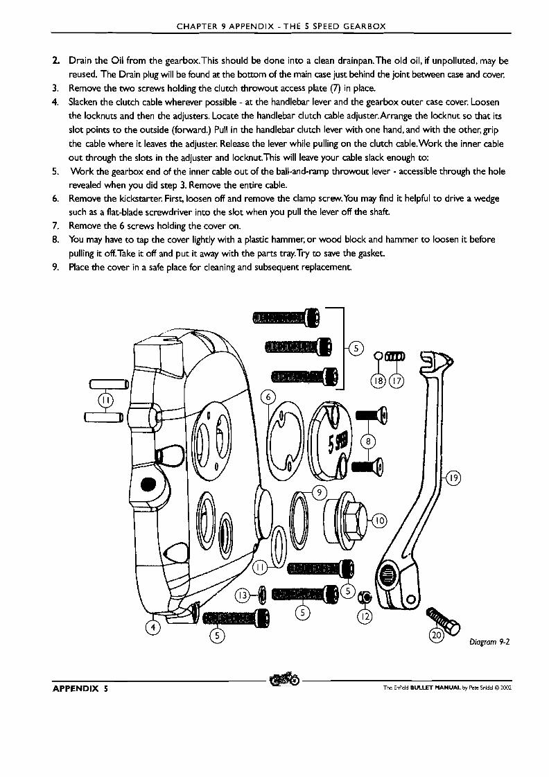
CHAPTER 9 APPENDIX -THE 5 SPEED GEARBOX
Drain the Oil from the gearbox.This should be done into a clean drainpan.The old oil, if unpolluted, may be reused. The Drain plug will be found at the bottom of the main case just behind the joint between case and cover.
Remove the two screws holding the clutch throwout access plate (7) in place. Slacken the clutch cable wherever possible - at the handlebar lever and the gearbox outer case cover. Loosen
the locknuts and then the adjusters. Locate the handlebar clutch cable adjuster.Arrange the locknut so that its slot points t o the outside (forward.) Pull in the handlebar clutch lever with one hand, and with the other, grip
the cable where it leaves the adjuster. Release the lever while pulling on the clutch cable.Work the inner cable
out through the slots in the adjuster and locknut.This will leave your cable slack enough to:
Work the gearbox end of the inner cable out of the ball-and-ramp throwout lever - accessible through the hole revealed when you did step 3. Remove the entire cable. Remove the kickstarter. First, loosen off and remove the clamp screw.You may find it helpful t o drive a wedge such as a flat-blade screwdriver into the slot when you pull the lever off the shaft.
Remove the 6 screws holding the cover on. You may have t o tap the cover lightly with a plastic hammer, o r wood block and hammer t o loosen it before
pulling it off.Take it off and put it away with the parts tray.Try to save the gasket. Place the cover in a safe place for cleaning and subsequent replacement.
Diagram 9-2
APPENDIX 5 The Enfield BULLET MANUAL by Pete Snidal O 2002
CHAPTER 9 APPENDIX - THE 5 SPEED GEARBOX
2. Carrier Plate (2.) This will give access to the kickstarter stop plate (1 9), allow the removal of the kickstarter shaft (1 3) andlor
replacement of its inner needle bearing (1 7), service to the kickstarter pawl assembly, ( 10,l 1,12), attention t o the
shifter link (24), bellcranklrocker assy. (22) and striker and spring, and servicelinspection of the gearbox internals. If
complete gearbox dismantling is anticipated, f irst remove the clutch.
I. Removal of the Rocker Shaft Pivot Pins (1 3) requires the use of Factory Tool 25 1534. Remove the pins from
the inner cover.
2. Remove the Cylindrical Pin (24.)
3. Repeat Step I. for the Stop Pin (28.) 4. Disconnect the Shifter Link (24) from the Rocker Shaft by removing one or both of the Link Pivot Pins (23.) OR
4. b) Remove the gearchange lever so that the gearchange shaft may be withdrawn with the Rocker Assembly in step 6.
5. Remove the kickstarter return spring anchor bolt (1 6). Be ready for a little torquing of the spring as the bolt is
withdrawn. Bolt, washer, and spring ( 14) into Parts Tray. 6. Depress the Striker Plate against its spring to clear the shifter pins on the camplate and withdraw the rocker
assembly.
7. Remove the Mainshaft Nut (9.) To keep the mainshaft from turning, select a gear by moving the rear wheel back
and forth while pulling upward on the change lever - top gear would be best, but any gear will likely do. Then
the rear brake may be used t o hold the Gearbox Mainshaft (2) from turning whilst you unscrew and remove
the Mainshaft Nut (9.) This is correctly a Left Hand Thread on earlier models, but since it's now apparently a
Nyloc, may be conventional.There is no mention in the factory literature of Left-Handedness on this shaft.
8. Remove the Four Carrier Plate Retaining Nuts (5.) 9. Withdraw the carrier Plate.Temporarily replacement of the kickstarter on its shaft will likely help - take just a
bit of the slack in the mechanism t o aid in withdrawing the Pawl assy from the Layshaft I s t gear.
10. Remove the 3 Camplate Pivot Plate (3 1) Screws (30) and withdraw the Plate.
I I. The entire gear cluster assy (both shafts) and camplate may now be removed as a unit It may help t o tap the mainshaft with a plastic hammer (or wood block and hammer, rock, etc.) from the clutch end.
12. Inspect the Layshaft Needle Bearing (22)at the back of the case cavity. It should turn with no scratchiness or resistance.To remove, if replacement is intended, f irst remove the circlip retainer. (2 1)
13. If the Countershaft (aka Sleeve Gear) is t o be removed, you will first have to follow the procedure for
Countershaft Sprocket RemovaLThen tap the countershaft gear inwards and retrieve it from inside the gearbox
14. Inspect the Countershaft Bearing for roughness and tightness as described above.Also for excessive "rocking"
(indicating radial play) by inserting the countershaft gear and trying for radial rocking. If it requires replacement,
remove the circlip (1 5) and heat the case "spitting hot" before driving the bearing inwards from the clutch side.
Be sure to drive it out straight and evenly. Ditto for replacement
15. It will likely be possible to replace theThe Countershaft Oil Seal - If Necessary - by prying it out from the
clutch side and replacing by driving the fresh one into place with a suitable mandrel. Be sure to make a note of
the position or the spacer piece (39) twixt bearing and sprocket. In dire cases, procedure 14 may be required
so that the seal may be driven out from the gearbox side.
The Enfield BULLET MANUAL by Pete Snidal @ 2002 APPENDIX 6

CHAPTER 9 APPENDIX - THE 5 SPEED GEARBOX
Inspection Of Gearbox Parts m Gears: Check dogs and corresponding dog slots for excessive roundness or swaging. Check teeth running
surfaces for excessive pitting, scoring, flaking, or roughness. Check that the splines are tight on their shafts - no
radial rocking possible.
m Bearings: Check for roughness of action, looseness of shafts indicating excessive clearance
m Shafts: Check running surfaces as for gears, splines for tightness, signs of excessive wear.
m Shifter Forks: check for excessive wear of gear finger surfaces,
m Shifter Fork Shaft check for excessive wear where forks have been running. m Camplate Pawl - look for excessive wear or swaging of point - where it interfaces with the camplate
m Camplate: - check for excessive width of shifter grooves due to wear. (Max 7.15 mm) Check pivot bearing for tightness of fit in camplate.
m Springs: - check all springs for stiffness - it would be best to compare them with new ones, or possibty even just to replace them.
m All running parts - check all parts against possible faults listed in troubleshooting charts
GEARBOX RE-ASSEMBLY
I. Before reassembling, ensure that all parts that have failed inspection are on hand, as well as fresh gaskets,
0-rings, and Seals.
2. If bearings or bushings have been removed, replace them and their retaining Circlips. Heat case spitting hot, and
ensure that bearings are pressed in straight and true. If re-fitting the Countershaft Bearing, allow case to cool
before fitting the NEW oil seal from the outside - coating it with engine oil will facilitate it sliding into place.
Note the Spacer (39) which goes on before the sprocket. Put it on now.
3. Be sure to fit a fresh Shifter Shaft Oil Seal (23). 4. If the camplate pawl has been removed, use Loc-TiteTM or some similar thread lock on the Pawl Bolt Threads
before installation and tightening. Check that the spring is installed with the hook pushing against the pawl lever.
APPENDIX 7 The Enfield BULLET MANUAL by Pete Snidal O 2002
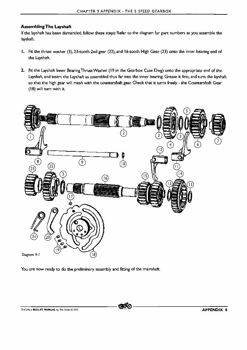
CHAPTER 9 APPENDIX - THE 5 SPEED GEARBOX
Assembling The Layshaft If the layshaft has been dismantled, follow these steps: Refer t o the diagram for part numbers as you assemble the layshaft.
I. Fit the thrust washer (3), 23-tooth 2nd gear (22), and 16-tooth High Gear (23) onto the inner bearing end of the Layshaft.
2. Fit the Layshaft Inner BearingThrust Washer (19 in the Gearbox Case Dwg) onto the appropriate end of the Layshaft, and insert the Layshaft as assembled thus far into the inner bearing. Grease it first, and turn the layshaft so that the high gear will mesh with the countershaft gear. Check that it turns freely - the Countershaft Gear (18) will turn with it.
You are now ready t o do the preliminary assembly and fitting of the mainshaft.
The Enfield BULLET MANUAL by Fete Snidal O 2002 APPENDIX 8
CHAPTER 9 APPENDIX - THE 5 SPEED GEARBOX
Mainshaft Reassembly
I. Slip the first Thrust Washer (3) over the outside end of the Mainshaft (2.)
2. Fit the 26-tooth Mainshaft 4th Gear (4) onto the shaft. Follow with the second Thrust Washer (3) and the
retaining Circlip (5) Fit the circlip into its groove in the shaft 3. Slip the 23-tooth Mainshaft 3rd Gear (6) onto the same end, dogs o u t 4. Slip the 20-tooth Mainshaft 2nd Gear ( I ) over the other end of the mainshaft. Large dogs t o the clutch side as
shown in the dwg. If in doubt, check t o see which dogs are cut t o engage with those on the countershaft gear. 5. Fit the Shifter Fork Shaft Circlip (I) onto the Shifter Fork Shaft (9) and fix it into its groove in the shaft. 6. Fit the Short-Boss Shifter Fork ( I I) onto the Shifter Fork Shaft (9) from the end furthest from the circlip as
shown in the diagram. Fork end closest t o the circlip.
7. Fit the Layshaft 3rdl4th Slider Shifter Fork (1 2) onto the Fork Shaft (2) as shown in dwg. Fork end to the center. 8. Fit the Long-Boss Fork (8) to the other end of the Fork Shaft (9) as shown in the diagram. Fork end t o the inside. 9. Lay the mainshaft assy on the bench.Assemble the shifter forks and shaft onto the mainshaft gear cluster as
assembled so far. Fit the mainshaft forks into the slots on their respective gears. 10. Locate the 3rdl4th Layshaft Slider Gear (1 5) and slip it onto its shifter fork Smaller gear of slider toward center,
Fork Shaft Circlip t o the outside. I I. Fit the Camplate onto the shifter forks with the fork bosses engaged in the appropriate camplate slots. Ensure
that the strikerplate rollers (1 9 X 4) are firmly located in their holes in the camplate - you might want t o use some grease t o ensure they stay in place.
12. Arrange the Assembly so that 3rd Gear is selected.This will have two camplate detent slots showing below the shifter fork shaft, four above it.
13. Ensure that the Detent Pawl (20) is facing downward before proceeding with step 14.
14. Locate the Camplate Pivot Plate (3 l), its three Cap Screws (30 X 3), and its fresh 0-ring (29). Slip the 0-ring over the boss on the inside surface of the plate, and put the plate and screws in an easy-to-reach spot near the
back of the gearbox
1 5. Carefully pick up this mess of gears, shafts, forks, and camplate with both hands. Holding it in its third gear position, introduce the Mainshaft assy. into its hole in the Countershaft, while simultaneously guiding the 3rdl4th Slider
Gear (1 5) onto its place on the Layshaft, and the inner end of the Shifter Fork Shaft into its hole in the back of the case as well.
16. Holding the gear clusterlshifter forklcamplate assy in place with your right hand, insert the Camplate Pivot Plate
into the rear of the gearbox, engaging the pivot into the Camplate. Fit the three fixing screws.Tighten the
screws. You are now ready t o complete assembly of the gear clusters.
17. First complete the Layshaft. Locate the two Layshaft First GearThrust Washers (1 3 X 2) and the Layshaft First Gear (1 4.) Slip on a thrust washer, then the gear - kickstarter ratchet ring outwards - and the second thrust washer.
18. Now the mainshaftAI1 that remains is the Mainshaft In Gear (7). Slip it onto the mainshaft dogs inward. N o washers. 19. Fit the Neutral Switch (32.) Be sure t o use a gasket 20. You are now ready t o fit the Kickstarter Pawl Assy (1 0- 12) and Carrier Plate.
APPENDIX 9 The Enfield BULLET MANUAL by Pete Snidal O 2002
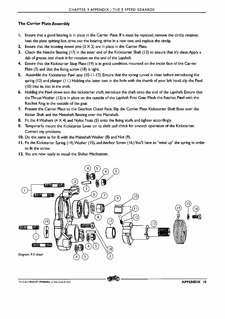
CHAPTER 9 APPENDIX - THE 5 SPEED GEARBOX
The Carrier Plate Assembly
I. Ensure that a good bearing is in place in the Carrier Plate. If it must be replaced, remove the circlip retainer,
heat the plate spitting hot, drive out the bearing, drive in a new one, and replace the circlip.
2. Ensure that the locating dowel pins (3 X 2) are in place in the Carrier Plate.
3. Check the Needle Bearing (1 7) in the inner end of the Kickstarter Shaft (1 3) to ensure that it's clean.Apply a
dab of grease, and check it for rotation on the end of the Layshaft 4. Ensure that the Kickstarter Stop Plate (1 9) is in good condition, mounted on the inside face of the Carrier
Plate (2) and that the fixing screw (1 8) is tight.
5. Assemble the Kickstarter Pawl assy (1 0- I 1 - 12). Ensure that the spring tunnel is clean before introducing the
spring (1 2) and plunger ( I I.) Holding the latter two in the hole with the thumb of your left hand, slip the Pawl
(10) into its slot in the shaft
6. Holding the Pawl down into the kickstarter shaft, introduce the shaft onto the end of the Layshaft Ensure that
theThrust Washer (1 3) is in place on the outside of the Layshaft First Gear. Mesh the Ratchet Pawl with the
Ratchet Ring in the outside of the gear. 7. Present the Carrier Plate to the Gearbox Outer Face. Slip the Carrier Plate Kickstarter Shaft Boss over the
Kicker Shaft and the Mainshaft Bearing over the Mainshaft 8. Fit the 4 Washers (4 X 4) and Nyloc Nuts (5) onto the fixing studs and tighten accordingly.
9. Temporarily mount the Kickstarter Lever on its shaft and check for smooth operation of the Kickstarter. Correct any problems.
10. Do the same as for 8. with the Mainshaftwasher (8) and Nut (9). I I. Fit the Kickstarter Spring (14),Washer (IS), and Anchor Screw (1 6.)You'll have to "wind up" the spring in order
to fit the screw.
12. You are now ready to install the Shifter Mechanism.
The Enfield BULLET MANUAL by Pete Snidal O 2002 APPENDIX 10
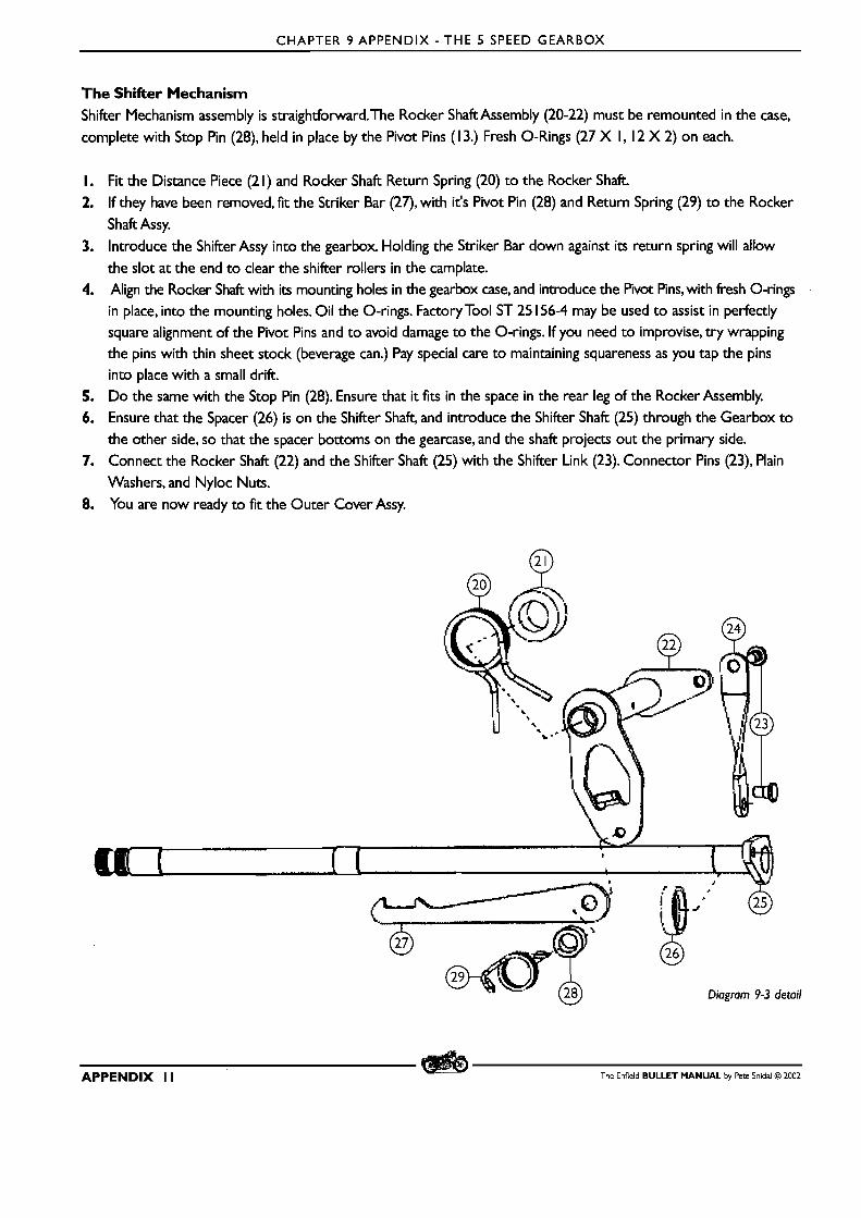
CHAPTER 9 APPENDIX - THE 5 SPEED GEARBOX
The Shifter Mechanism Shifter Mechanism assembly is straightforward.The Rocker Shaft Assembly (20-22) must be remounted in the case, complete with Stop Pin (28), held in place by the Pivot Pins (1 3.) Fresh 0-Rings (27 X l, 12 X 2) on each.
I. Fit the Distance Piece (2 1) and Rocker Shaft Return Spring (20) to the Rocker Shaft. 2. If they have been removed, fit the Striker Bar (27), with it's Pivot Pin (28) and Return Spring (29) to the Rocker
Shaft Assy. 3. Introduce the Shifter Assy into the gearbox. Holding the Striker Bar down against its return spring will allow
the slot at the end to clear the shifter rollers in the camplate. 4. Align the Rocker Shaft with its mounting holes in the gearbox case, and introduce the Pivot P i n ~ , ~ t h fresh 0-rings
in place, into the mounting holes. Oil the 0-rings. Factory Tool ST 25 156-4 may be used t o assist in perfectly square alignment of the Pivot Pins and to avoid damage to the 0-rings. If you need to improvise, try wrapping the pins with thin sheet stock (beverage can.) Pay special care to maintaining squareness as you tap the pins into place with a small drift.
5. Do the same with the Stop Pin (28). Ensure that it fits in the space in the rear leg of the Rocker Assembly. 6. Ensure that the Spacer (26) is on the Shifter Shaft, and introduce the Shifter Shaft (25) through the Gearbox to
the other side, so that the spacer bottoms on the gearcase, and the shaft projects out the primary side. 7. Connect the Rocker Shaft (22) and the Shifter Shaft (25) with the Shifter Link (23). Connector Pins (23), Plain
Washers, and Nyloc Nuts. 8. You are now ready to fit the Outer Cover Assy.
Diagram 9-3 detail
APPENDIX I I The Enfield BULLET MANUAL by Pete Snldal O 2002
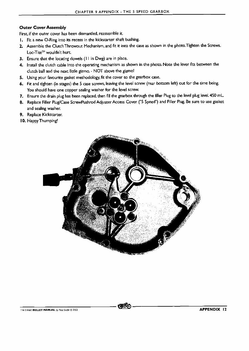
CHAPTER 9 APPENDIX - THE 5 SPEED GEARBOX
Outer Cover Assembly First, if the outer cover has been dismantled, reassemble it. I. Fit a new 0-Ring into its recess in the kickstarter shaft bushing. 2. Assemble the Clutch Throwout Mechanism, and fit it into the case as shown in the photo.Tighten the Screws.
LOC-TiteTM wouldn't hurt.
3. Ensure that the locating dowels (I I in Dwg) are in place. 4. Install the clutch cable into the operating mechanism as shown in the photo. Note the lever fits between the
clutch ball and the next little gizmo. - NOT above the gizmo!
5. Using your favourite gasket methodology, fit the cover to the gearbox case.
6. Fit and tighten (in stages) the 5 case screws, leaving the level screw (rear bottom left) out for the time being. You should have one copper sealing washer for the level screw.
7. Ensure the drain plug has been replaced, then fill the gearbox through the filler Plug t o the level plug level. 450 m L 8. Replace Filler PlugICase ScrewPushrod Adjuster Access Cover ("5 Speed") and Filler Plug. Be sure t o use gasket
and sealing washer. 9. Replace Kickstarter. 1 0. Happy Thumping!
The Enfield BULLET MANUAL by Pete Snidal O 2002 APPENDIX 12
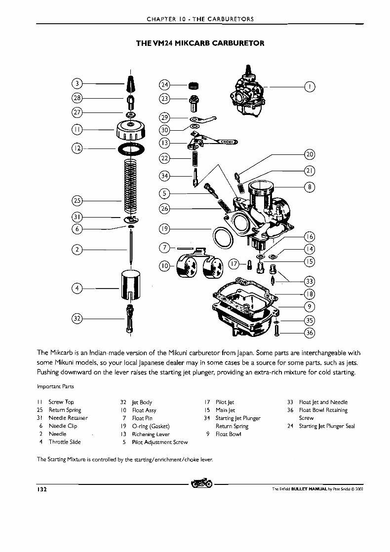
CHAPTER 10 - THE CARBURETORS
THE VM24 MIKCARB CARBURETOR
The IYikcarb is an Indian-made version of the Plikuni carburetor from Japan. Some parts are interchangeable with
some IYikuni models, so your local Japanese dealer may in some cases be a source for some parts, such as jets.
Pushing downward on the lever raises the starting jet plunger, providing an extra-rich mixture for cold starting.
Important Parts
I I Screw Top 32 jet Body 17 Pilot jet 33 Float jet and Needle 25 Return Spring 10 Float Assy 15 Main jet 36 Float Bowl Retaining 3 1 Needle Retainer 7 Float Pin 34 Starting jet Plunger Screw
6 Needle Clip 19 0-ring (Gasket) Return Spring 24 Starting jet Plunger Seal 2 Needle 13 Richening Lever 9 Float Bowl 4 Throttle Slide 5 Pilot Adjustment Screw
The Starting Mixture is controlled by the starting/enrichment/choke lever.
132 The Enfield BULLET MANUAL by Pete Snidal O 2002
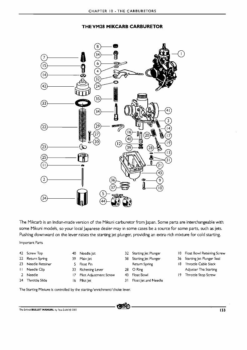
CHAPTER I 0 - T H E CARBURETORS
THE VM28 MIKCARB CARBURETOR
The Mikcarb is an Indian-made version of the Mikuni carburetor fromlapan. Some parts are interchangeable with
some Mikuni models, so your local Japanese dealer may in some cases be a source for some parts, such as jets.
Pushing downward on the lever raises the starting jet plunger, providing an extra-rich mixture for cold starting.
Important Parts
42 Screw Top 40 Needle Jet 32 Starting Jet Plunger 10 Float Bowl Retaining Screw
22 Return Spring 39 Main Jet 38 Starting Jet Plunger 36 Starting Jet Plunger Seal
23 Needle Retainer 5 Float Pin Return Spring 18 Throttle Cable Slack
I I Needle Clip 33 Richening Lever 28 0 Ring Adjuster The Starting
2 Needle 17 Pilot Adjustment Screw 43 Float Bowl 19 Throttle Stop Screw
24 Throttle Slide 16 Pilot Jet 3 1 Float Jet and Needle
The Starting Mixture is controlled by the starting/enrichment/choke lever.
The Enfield BULLET MANUAL by Pete Snidal O 2002 133
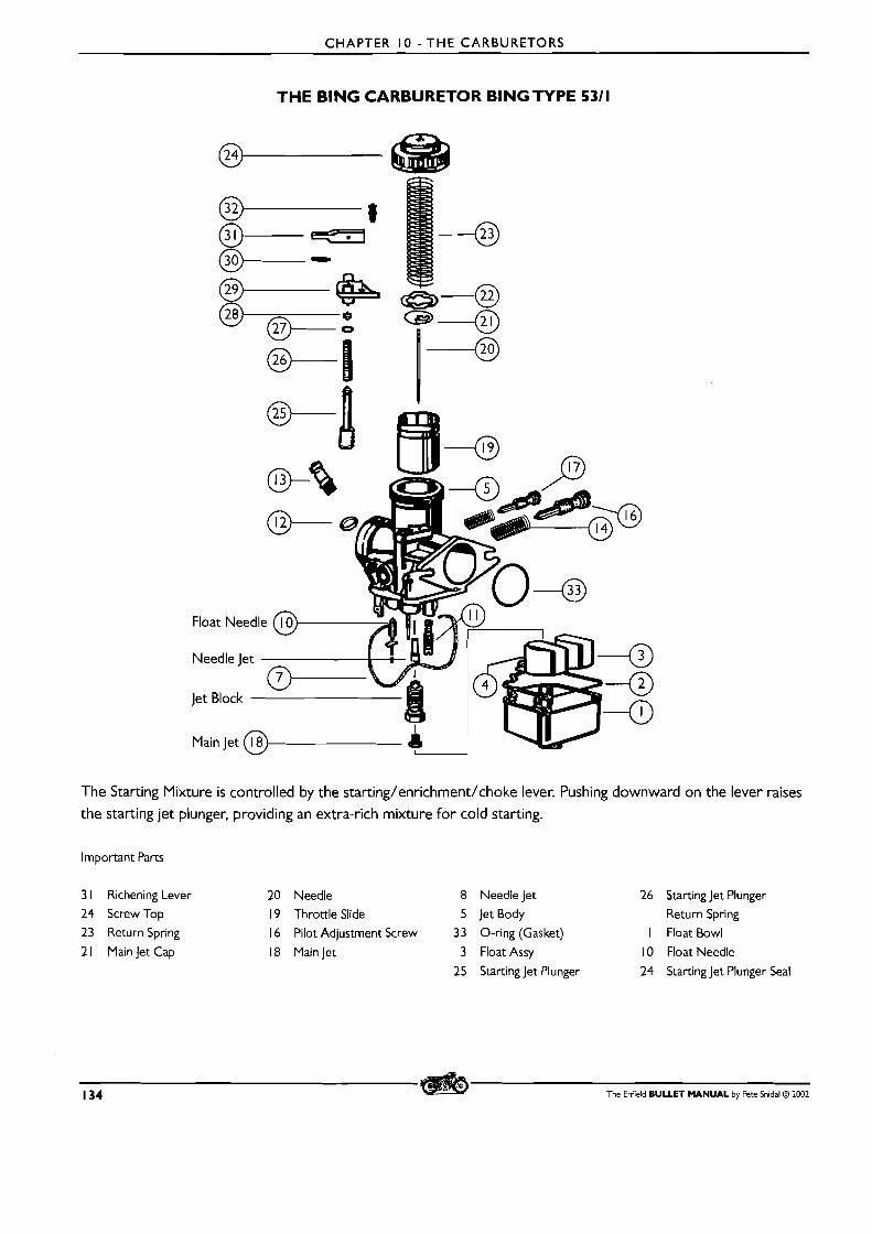
CHAPTER I 0 - T H E CARBURETORS
THE BlNG CARBURETOR B I N G N P E 5311
The Starting Mixture is controlled by the starting/enrichment/choke lever. Pushing downward on the lever raises
the starting jet plunger, providing an extra-rich mixture for cold starting.
Important Parts
3 1 Richening Lever 20 Needle 8 Needle Jet
24 Screw Top 19 Throttle Slide 5 Jet Body
23 Return Spring 16 Pilot Adjustment Screw 33 0-ring (Gasket)
2 1 Main Jet Cap 18 Main Jet 3 Float Assy
25 Starting Jet Plunger
26 Starting Jet Plunger
Return Spring
I Float Bowl
10 Float Needle
24 Starting Jet Plunger Seal
134 The Enfield BULLET MANUAL by Pete Snidal @ 1002
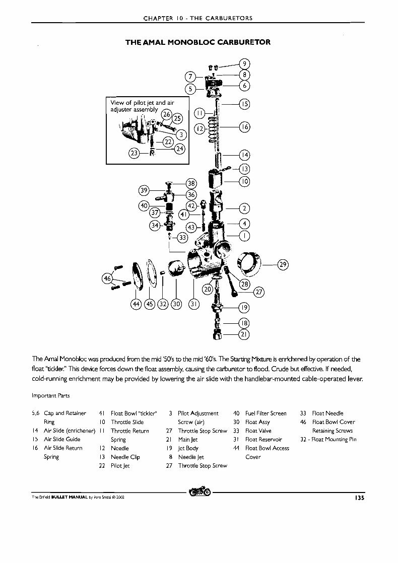
CHAPTER I 0 - THE CARBURETORS
THE AMAL MONOBLOC CARBURETOR
View of pilot jet and air
The Amal Monobloc was produced from the mid '50's to the mid '60's. The Starting Mixture is ennchened by operation of the float "tickler." This device forces down the float assembly, causing the carburetor to flood. Crude but effective. If needed, cold-running enrichment may be provided by lowering the air slide with the handlebar-mounted cable-operated lever.
Important Parts
5,6 Cap and Retainer 4 1 Float Bowl "tickler" 3 Pilot Adjustment 40 Fuel Filter Screen 33 Float Needle
Ring 10 Throttle Slide Screw (air) 30 Float Assy 46 Float Bowl Cover
14 Air Slide (enrichener) I I Throttle Return 27 Throttle Stop Screw 33 Float Valve Retaining Screws
15 Air Slide Guide Spring 21 Main Jet 3 1 Float Reservoir 32 - Float Mounting Pin
16 Air Slide Return 12 Needle 19 Jet Body 44 Float Bowl Access
Spring 13 Needle Clip 8 Needlejet Cover
22 Pilotlet 27 Throttle Stop Screw
The Enfield BULLET MANUAL by Pete Snidal O 2002 135
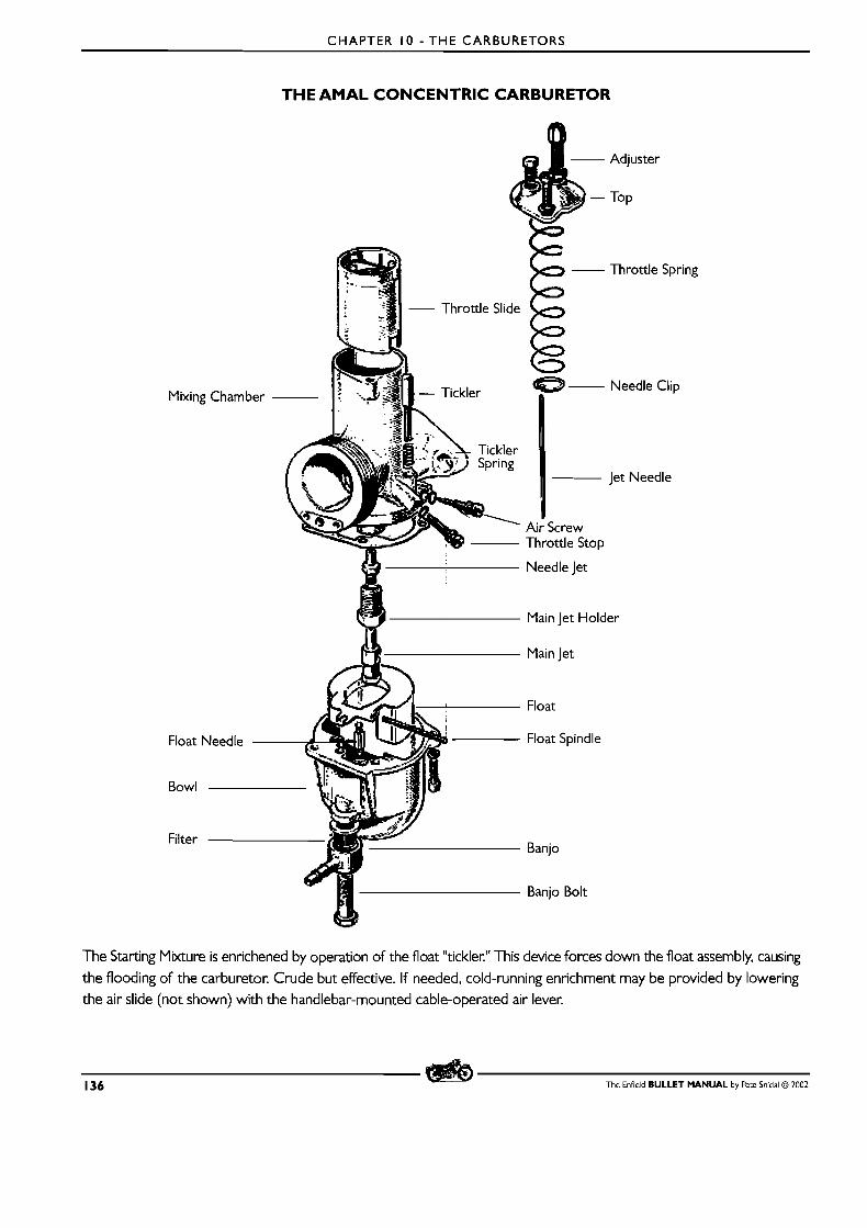
CHAPTER 10 - THE CARBURETORS
Mixing Chamber
Float
Bowl
Filter
THE AMAL CONCENTRIC CARBURETOR
E - Throttle Spring
Needle Clip
Jet Needle
~ i ; screw Throttle Stop
Needle Jet
Main Jet Holder
Main Jet
Float
Float Spindle
Banjo
Banjo Bolt
The Starting Mixture is enrichened by operation of the float "tickler." This device forces down the float assembly, causing
the flooding of the carburetor. Crude but effective. If needed, cold-running enrichment may be provided by lowering the air slide (not shown) with the handlebar-mounted cable-operated air lever.
136 The Enfield BULLET MANUAL by Pete Snidal Q 2002
CHAPTER I 0 - THE CARBURETORS
Adjustment The purpose of the carburetor is t o mix fuel with air entering the intake passage. The air/fuel ratio is fairly critical,
and for this reason, adjustments have been provided. They cover 4 ranges of throttle opening.
m High Range: 3/4 to Full Throttle - Controlled by Main Jet Size
m lYid Range: 1 /4 t o 3/4 Throttle - Controlled by Needle Position and Needle Jet Size.
m Low Range: 0- 1 /8 Throttle - Controlled by Pilot Jet
Transition - around 1 /8 throttle, the angle of the Throttle cutaway on the throttle slide has some effect on
the transition of opening from 1 /8 to 1 /4 throttle.
The Float Circuit The first place your fuel goes is to the float valve - into the float circuit. The float valve is a needle valve which is
normally open, but which is closed by a lever attached to a float, which is raised by fuel level in the float bowl.
When the proper level in the float reservoir (9) is reached, the float valve (33) is closed by the rising float assy
(1 8). Thus there is a constantly-regulated level in the bowl from which to draw for the main, needle, and pilot
jets. Fuel flow is through the float valve into the float bowl, and out through the jet block (32), starting with the
main jet, and then through the needle jet, into the airflow through the carburetor and into the combustion
chamber. A t idle openings, fuel flow is directly through the idle jet
Your float level is determined by adjusting the angle of the float lever where it contacts the needle float valve.
This seldom requires adjustment - the sign that it does is that proper mixture cannot be attained by jetting changes.
Flooding Caused by Sticking Float It is common with the Bullet, especially during the initial ownership period, for rust to work i ts way from the fuel tank through the fuel system to the carburetor, and this often gets stuck in the float valve, (33) holding it open,
resulting in fuel running out the overflow tube. A temporary fix can sometimes be done by giving the float bowl
a sharp rap with a spanner or rock, but in most cases this will have to be cleaned by removing the float bowl - the four fixing screws (36) - and possibly the float assy ( 1 8) and needle (33) by sliding out the mounting pin (7). Turn the fuel off before removing the bowl, and once the float needle (33) is out of the valve port (33), run
some fuel into a suitable receptacle placed under the carburetor until the fuel comes clean. Test by replacing the
needle and float assy, and GENTLY hold the floats up against the needle valve seat with fuel tap on. N o fuel
should run unless pressure is released on the float assy. Be sure also to clean the bottom of the bowl before
replacing. Check also that there is adequate fuel flow - if it takes any more than a minute to fill a litre container,
the tank should be removed and flushed, and the filter screen in the fuel tap should be cleaned. For more details
on dealing with rusty fueltank, see Chapter 3.
Checking and Adjusting Mixture Ranges There are two stages in the adjustment of each jet range: checking and then, if necessary, adjusting.
MID-RANGE
The most important jet range is the mid-range needle setting, since this is the one most used - from 1 /4 to 3/4 throttle.
The mixture ratio is determined by the relative height of the needle in the needle (3) in the needle jet (top of 32). If the machine is ridden at the top of the throttle range (3/4-Full), it is very important that the main jet tuning be
correct as well. This is done by physically changing to jets of different sizes - they screw into the bottom of the jet block (32).
The Enfield BULLET MANUAL by Pete Snidal O 2002 137
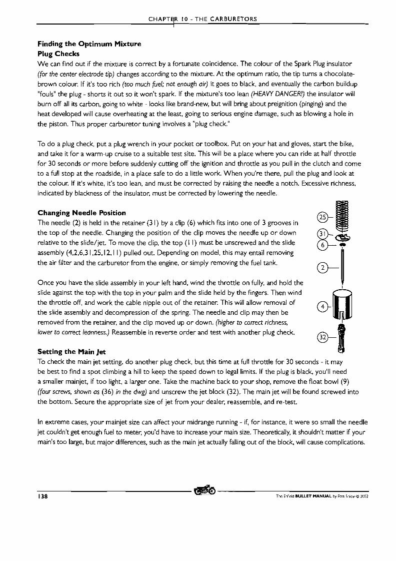
CHAPTHR I 0 - THE CARBURETORS
Finding the Optimum Mixture Plug Checks W e can find out if the mixture is correct by a fortunate coincidence. The colour of the Spark Plug insulator
(for the center electrode tip) changes according to the mixture. A t the optimum ratio, the tip turns a chocolate-
brown colour. If it's too rich (too much fiel; not enough air) it goes to black, and eventually the carbon buildup "fouls" the plug - shorts it out so it won't spark. If the mixture's too lean (HEAVY DANGER!) the insulator will burn off all its carbon, going to white - looks like brand-new, but will bring about preignition (pinging) and the
heat developed will cause overheating at the least, going t o serious engine damage, such as blowing a hole in
the piston. Thus proper carburetor tuning involves a "plug check."
To do a plug check, put a plug wrench in your pocket or toolbox. Put on your hat and gloves, start the bike, and take it for a warm-up cruise t o a suitable test site. This will be a place where you can ride at half throttle for 30 seconds or more before suddenly cutting off the ignition and throttle as you pull in the clutch and come to a full stop at the roadside, in a place safe t o do a little work. When you're there, pull the plug and look at
the colour. If it's white, it's too lean, and must be corrected by raising the needle a notch. Excessive richness, indicated by blackness of the insulator, must be corrected by lowering the needle.
Changing Needle Position The needle (2) is held in the retainer (3 1) by a clip (6) which fits into one of 3 grooves in
the top of the needle. Changing the position of the clip moves the needle up o r down relative t o the slide/jet. To move the clip, the top ( I I ) must be unscrewed and the slide
assembly (4,2,6,3 1,25,12,1 l ) pulled out. Depending on model, this may entail removing
the air filter and the carburetor from the engine, o r simply removing the fuel tank.
Once you have the slide assembly in your left hand, wind the throttle on fully, and hold the v slide against the top with the top in your palm and the slide held by the fingers. Then wind
the throttle off, and work the cable nipple out of the retainer. This will allow removal of the slide assembly and decompression of the spring. The needle and clip may then be
removed from the retainer, and the clip moved up o r down. (higher to correct richness,
lower to correct leanness.) Reassemble in reverse order and test with another plug check.
@B Setting the Main Jet @!l To check the main jet setting, do another plug check, but this time at full throttle for 30 seconds - it may
be best to find a spot climbing a hill to keep the speed down t o legal limits. If the plug is black, you'll need a smaller mainjet, if too light, a larger one. Take the machine back to your shop, remove the float bowl (9) (four screws, shown as (36) in the dwg) and unscrew the jet block (32). The main jet will be found screwed into
the bottom. Secure the appropriate size of jet from your dealer, reassemble, and re-test.
In extreme cases, your mainjet size can affect your midrange running - if, for instance, it were so small the needle
jet couldn't get enough fuel to meter, you'd have to increase your main size. Theoretically, it shouldn't matter if your
main's too large, but major differences, such as the main jet actually falling out of the block, will cause complications.
138 The Enfield BULLET MANUAL by Pete Snidal @ 2002
CHAPTER I 0 - THE CARBURETORS
The Pilot Jet Setting The pilot jet covers only the idle range (0- 1 /8 throttle.) To adjust idle, or tick-over, first ensure that there is a
minimum slack in the throttle cable - about I /8"-3mm. Take the machine the machine for a short ride to warm it
up, and put it on the center stand with engine running. "Blip" the throttle to ensure that the cable has gone slack,
and adjust the throttle stop screw (on the side of the carburetor) to a position in which it will, when tightened,
raise the throttle slide up and down to ensure that it is in fact changing the throttle opening. Adjust the throttle
stop screw for minimum and cleanest-running idle speed, and then adjust the pilot screw (5) to reduce the idle
speed. Work back and forth with the two screws until the best, cleanest, lowest idle is attained.
Ensure also that the throttle cable is unobstructed. Move the handlebars back and forth to test for cable complications
- if the cable routing is bad, the idle will rise and fall as you move the bars. If this occurs, experiment with different
routings of the cable to correct this problem.
That's about all there is to getting your carb tuning "in the ballpark." Do remember that too lean a mixture will
bring about overheating, often detonation and subsequent holing of the piston(s). Too rich will result in plug
fouling from carbon buildup. Happy chocolate plug tips!
The Enfield BULLET MANUAL by Pete Snidal O 2002 139
CHAPTER I I - ELECTRICAL W O R K
CHAPTER I I - ELECTRICAL WORK
SORTING OUT ELECTRICAL DIFFICULTIES
The Principles A basic understanding of the principles of electricity is essential to the mastery of electrical troubleshooting. Here
is a short primer:
The Electrical Circuit: Current Flow The basis of electrical activity is current flow through a loop, or electrical circuit, from a power source - the battery
or alternator - through conductors - wires, through various elements on the way - switches and load devices, such
as lights, horn, ignition coil, back to the power source, generally through the vehicle chassis, which is used as a
return path to simplify things, and to save wire.
Resistance The load devices, and the conductors - switches, connections, etc., - consume electrical energy, and offer resistance
to the current flow, and the supply devices supply energy, to overcome this resistance. There is a balance in every
circuit - the voltage consumed will be equal to the voltage supplied - a 12 Volt light bulb, in conjunction with the
conductors and switches in its circuit from a 12V battery, uses up all 12 Volts. Put another way, the sum of the load
voltages will be equal to the applied voltage. - And, don't forget, only in a perfect world is there IVO resistance in
ANY of the elements other than the load - the switches, the various connections, and the conductors themselves
all contribute in some degree to the total resistance, and therefore total load.
Measuring Electrical Quantities The basic three considerations are Voltage, or Electrical Pressure, the speed of current flow, or Amperage, and
Resistance to electrical Flow offered by various elements in the circuit, considered in Ohms. Increasing the pressure,
or Voltage offered to a circuit will increase the speed of flow, or Amperage. Similarly, adding to the resistance
offered to the voltage will decrease the current flow. The formula, well known as Ohm's Law, Looks like this:
In which I = Current in Amperes, E=Voltage in Volts, R=Resistance in Ohms. A current of I A will be present in a circuit in which IV is presented to a total resistance (wires, connecton, switches, and load device) of I Ohm. I, or current,
is constant in every element of each single circuit.
A final quantity that needs mention is Watts, or total Power, calculated as Amp-Volt product. A 12V Load Device
which draws a I A current consumes a power of I X 12= 12 Watts. A 60W Halogen Headlamp requires 60/ 12=5A.
This is all we need to understand to troubleshoot and rectify electrical problems.
140 The Enfield BULLET MANUAL by Pere Snidal O 2002
CHAPTER I I - ELECTRICAL WORK
Tools and Materials
LEVEL I TOOLS - may be carried in the machine's toolbox:
m Test Light
m Wire Strippers
m Spare Wire (-3 IYtrs)
m Plastic Tape
m Spare Fuses m Spare Light Bulbs
m Spare Contact Breaker Points
LEVEL 2 TOOLS - for the serious electrical tech
m Solde ing Gun
m Solder (Resin Core - electrical) m Crimp Connectors
m Crimping Pliers
m Spools of wire - various colours m Shrink Tubing
Testing for Power Supply Since power availability is essential to current flow, the first step in solving an electrical problem is to ensure that power is available to the circuit. For this, we need a test lamp, or a voltmeter. (Usually supplied as Multimeten, for this work these are most commonly used set to Volts, on the I - 15V scale.) In the case of failure of any device, the first step is to ensure the presence of voltage, starting at the very source - the battery.
Verifying Voltage To check at the battery, connect the ground clip of your test light or meter to the grounded battery terminal -
not the chassis of the machine itself, as the grounding of the battery terminal should always be the first suspect.
Touching the probe of the light or meter to the ungrounded terminal of the battery should light the test lamp,
or produce a reading of around 12.5V. Then, verify the ground connection to the chassis by connecting the test clip
to the chassis - a fin of the cylinder head is a reliable one - and check again at the battery "hot" terminal. If the light
lights, the ground is working. (IVote, it may be presenting a resistance to higher loads, but light the test lamp or
show a voltage on the meter. More on this ldter - "voltage drops."
The Diagrams The following pages contain the 3 types of wiring diagrams used by the Bullet - The US/Canada IYodels,
The UK IYodels and the The Home (Indian) Models.
Schematic Diagrams - it should be noted that most wiring diagrams (eg. these) are schematic. This means that
the elements are not shown in positions relating to their actual positions on the machine; they are drawn to show
electrical relativity only.
The Enfield BULLET MANUAL by Pete Snidal O ZOO2 141
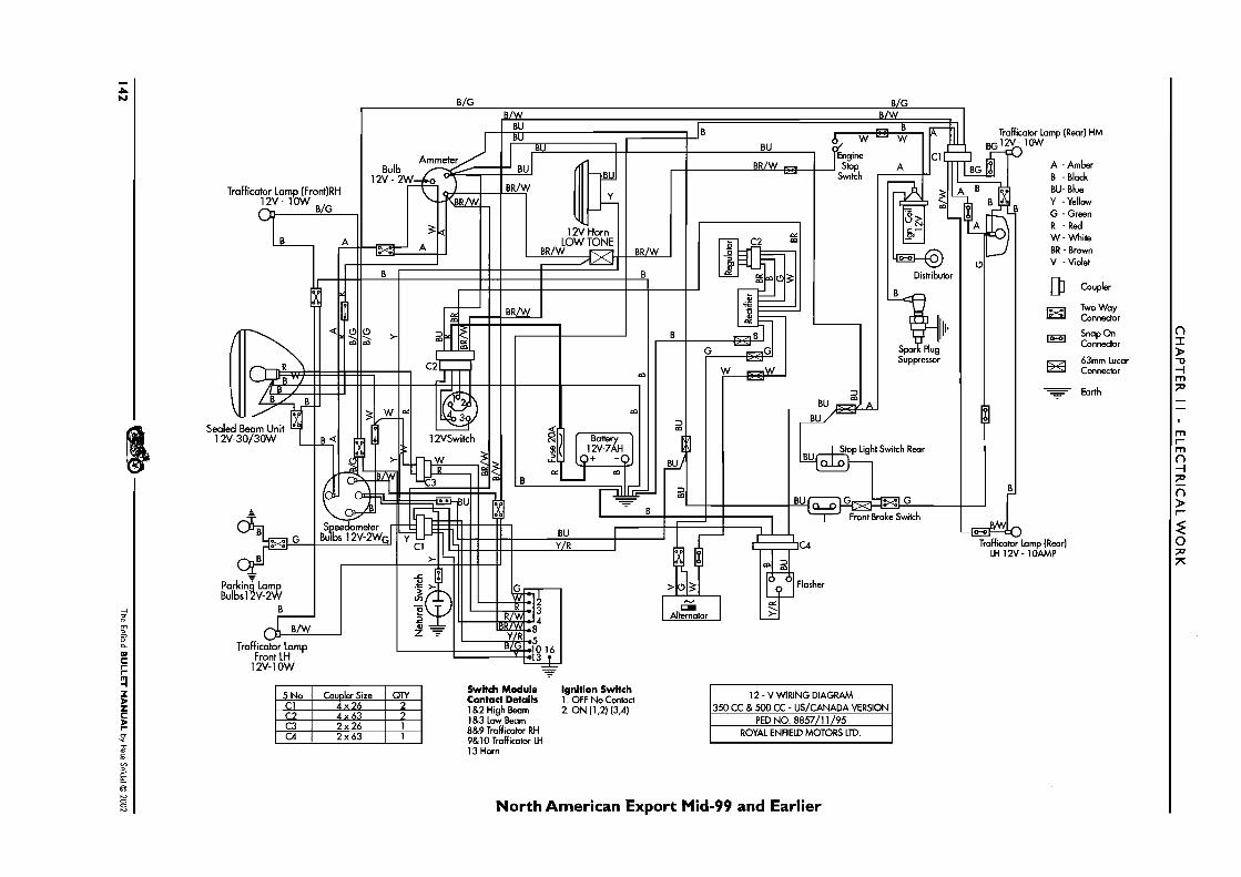
Switch Module Ignition Switch Contact Details 1. OFF No Contact 1 &2 High Beam 2. O N (1,2) (3,4) 1 &3 Low Beam 8&9 Tmff icabr RH 9&10 Traff icator LH 13 Horn
North American Export Mid-99 and Earlier

CHAPTER I I - ELECTRICAL WORK
The Enfield BULLET MANUAL by Pete Snidal O 2002 143
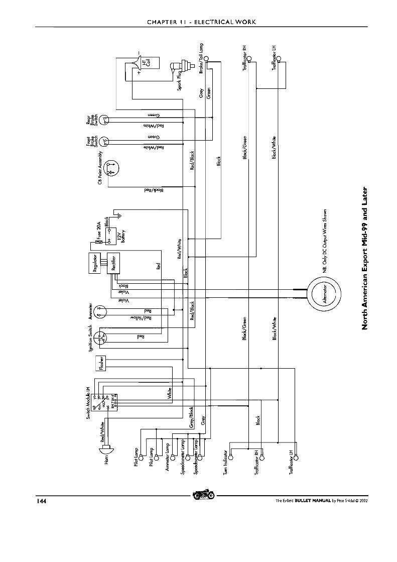
CHAPTER I I - ELECTRICAL WORK
144 The Enfield BULLET MANUAL by Pete Snidal O 2002
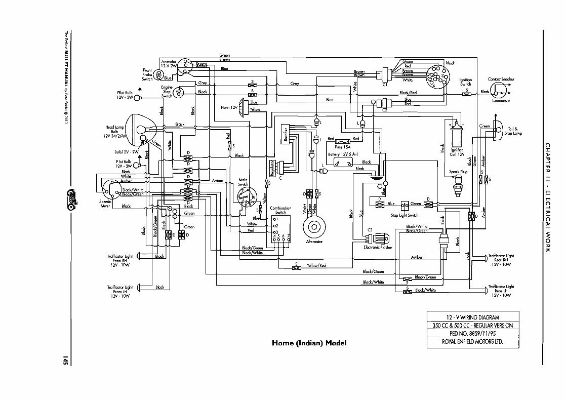
Green
12'4- IOW
Home (Indian) Model

CHAPTER I I - ELECTRICAL WORK
146 The Enfield BULLET MANUAL by Pete Snidal O 2002
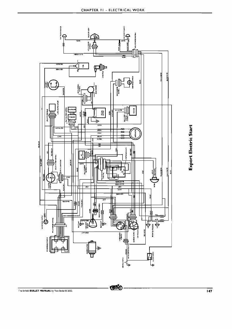
CHAPTER I I - ELECTRICAL WORK
The Enfield BULLET MANUAL by Pete Snidal O 2002 147
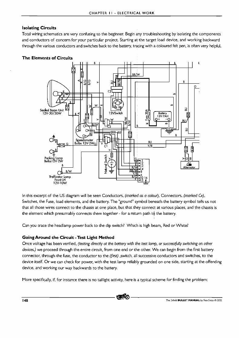
CHAPTER I I - ELECTRICAL WORK
Isolating Circuits Total wiring schematics are very confusing to the beginner. Begin any troubleshooting by isolating the components
and conductors of concern for your particular project. Starting at the target load device, and working backward
through the various conductors and switches back to the battery, tracing with a coloured felt pen, is often very helpful.
The Elements of Circuits
In this excerpt of the US diagram will be seen Conductors, (marked as a colour), Connectors, (marked Cx), Switches, the Fuse, load elements, and the battery. The "ground" symbol beneath the battery symbol tells us not
that all those wires connect to the chassis at one place, but that they connect at various places, and the chassis is
the element which presumably connects them together - for a return path t4 the battery.
Can you trace the headlamp power back to the dip switch? Which is high beam, Red or White?
Going Around the Circuit -Test Light Method Once voltage has been verified, (testing directly at the battery with the test lamp, or successfully switching on other
devices,) we proceed through the entire circuit, from one end or the other. We can begin from the first battery
connector, through the fuse, the conductor to the (fint) ,switch, all successive conductors and switches, to the
device itself. O r we can check for power, with the test lamp reliably grounded on one side, starting at the offending
device, and working our way backwards to the battery.
More specifically, if, for instance there is no taillight activity, here is a typical scheme for finding the problem:
148 The Enfield BULLET MANUAL by Pete Snidal O 2002
CHAPTER I I - ELECTRICAL WORK
B First verify that your battery is good, by trying and checking other lights - the headlight, for example. B Verify that the bulb and/or i ts connection in the socket is good. Remove the lens and try a known-good bulb,
cleaning the connections to the pips on the end, and the interior of the socket. If the good bulb doesn't light, first try the ground connection. Use your jumper wire, and jump a connection
from the taillight body to the grounded terminal of the battery. (Taillight switched on.) If this produces light, correct
the poor ground connection of taillight body to mudguard, and of mudguard to frame. B If jumping to ground didn't do anything, check for voltage at the interior connections inside the bottom of the
bulb socket. Be careful not to short the connector to the outside of the bulb socket - this will blow your fuse.
Connect the other side of the test bulb to a known-good ground (the grounded battery terminal is best) If your
test bulb fails to light, you have narrowed the problem down to the taillight supply.
Trace back to the first connection. In the case of The Regular (Home) Version, it will be seen that both stoplight and taillight lines connect through connector C4. One of these, the Amber one, connects back to the Main switch, to terminal 5.
B With one line of our test lamp connected to a known-good ground, and the light switch in the O N position, check the output wire to the taillight. Then check the amber wire as it goes IN to the connector C4. If it lights, you know the the wire, the Main Switch, and the switch supply are good. If not, check the Main Switch Supply wire - if it's good going in, and not coming out, you know the switch is faulty. This would also be indicated if other output devices from the same switch, such as the headlight, worked, but the taillight did not.
THEJUPIPER IYETHOD: The Jumper method may be used to verify a bad switch at this point. If the connections
from switch to taillight , and the light itself, and its ground, are all good, "jumping" the taillight input wire with a
jumper wire, the other end of which is connected to the "hot" (non-grounded) battery terminal will test the connection from the Main Switch terminal 5 through C4 to the taillight. If this is successful, but turning on the
Lights at the Main Switch doesn't light the taillight, we know the switch is faulty.
B A WORD Oh1 JUMPING: There is much power in your battery - enough to light up a wire and bum off the insulation,
possibly starting a fire. NEVER leave a hot jumper wire unattended, and never let it contact the chassis, particularly
in the area of the fuel system. - although a momentary quick contact to a safe place on the frame will produce a spark which will verify its "hotness." (Caution: if connected througf~ the fuse, this will blow the @e. Use the test lamp!)
Locating Circuit Elements It is often challenging, when working from the wiring diagram, to locate the actual elements shown on the diagram
on the machine itself. The larger and more obvious ones, such as the battery, the headlight, or the ignition coil, are
little trouble - although it may be necessary to remove certain things to gain access. But the various connectors -
often a source of problems due to corrosion - are more challenging. They are generally in places to facilitate
removal of such components as the rear mudguard, the casquette or headlight, etc.
The Enfield BULLET MANUAL by Pete Snidal O 2002 149

CHAPTER I I - ELECTRICAL W O R K
Navigating Through Switches The Factory Diagrams give legends for the switches. For example, the Regular 12V diagram (see page 143) tells us
that the Ignition Switch is wired as follows:
Switch Position Connections Rationale
OFF : No Connections . Noth~ng is Connected to Anything l
IGNITION i (2,4,6) (1 0.14) 2-4-6 means the rectifier output, the coil, and the ammeter output are connected together. The 10- 14
connection connects the Red wire from the fuse through the Blue line to the battery side of the ammeter.
' Thus current will flow from the battery through the switch, the ammeter, the coil, and the points to ground,
and that current flow will register on the ammeter. When the engine starts, rectifier output will flow , through the ammeter, the ign~tion sw~tch, and the fuse, to the battery, also registering on the ammeter.
EMG (2,4,16) (8.1 2) 2-4-6 as for normal ignit~on, with an 8- 12 connection to the connector C l. 8- 12 are not apparently connected to anything in this diagram.
This is how you trace the power flow through a switch.
Voltage Drop Because of the difficulty of getting into some areas of the circuitry, some points are easier to reach than others.
Furthermore, it is often useful to be able to find out if, and just how much, power is being dissipated by a faulty
switch or poor connection which, although still passing current, is offering an excessively high parasitic resistance to
the current flow. For these reasons, a voltmeter-oriented method of testing is worth mentioning: Checking For
Voltage Drop.
Here's how it works. Remember, the total voltage drawn by all elements as we trace around a circuit will be equal
to the supply voltage. This means that, in an ideal world, the entire voltage of the battery, say 12.3V engine off, will
be present at the headlight high beam. So, if we connect the voltmeter directly to the high beam wires at the rear of the headlight unit, with the headlight on, we should get a reading of 12.3V - this load voltage balances the supply voltage I: I. But, if one of the elements we have assumed to be showing total conductivity, ie zero resistance, is
consuming some of our power, we may get a reading at the light of only say I 1.8V. With this challenge, we then
need to find the offending element(s) and fix it/them. So we begin with checking the chassis return path - the
"ground." With the positive meter probe on the more positive end of the circuit - check by first just "striking" the
final probe and watching which way the needle bounces on analog meters and the other on the grounded battery terminal, we look for a voltage reading. If any resistance is being presented between the headlight ground terminal
and the battery ground terminal, we will see a voltage - it will be a small one, so for analog meters, we will have to
set the voltage range small - 1.5V or less - some meters have a .5V scale. If we get a reading, we will then have to
clean up all ground connections, or "jump" the headlight ground wire with a direct wire from it to the battery.
Similarly, all other elements can be checked. A voltage drop reading from the hot battery terminal to the headlight
hot terminal may also show a reading. (nb the device must be operating for this method to show results.) If so, we
would then narrow it down to each element in turn - is there a reading across the fuse holder? Dirty connections!
How about between the fuse and the switch? Connector C2! O r the ignition switch and the headlight?
150 The Enfield BULLET MANUAL by Pete Snidal C3 2002

CHAPTER I I - ELECTRICAL WORK
Combination Switch! The Voltage Drop method is better than the normal test-lamp tracing method in that it not
only detects total loss of current path, but also quantifies lesser resistances as well.
A Final Example: Ignition Checking Let's go through a final, and simple example. Say the machine won't start, and we pull the plug and find that we
can't get any spark. We of course substitute our fresh plug (which we ALWAYS carry, complete with plug wrench!) and
still can't get a spark. So we will then pull out our test lamp and look for some power.
provides a connection to battery (-) through
the chassis ground.
First, we would check at the contact breaker, Brown because it is easiest to get to. With the
points open, (and switch on) there should be Blue
If we found no power to the moving point (with the points open, of course - otherwise the coil would be using up
all of the 12V from the battery, ie there should be no voltage drop across closed points), we would then go to the
next spot up the circuit - the coil (-) terminal. If no power there, then the (+) terminal.
Ammeter voltage present, since there is a connection
back from the moving point through the coil, U
the switch (twice), the ammeter, and the fuse d to the battery (-). The non-moving point
Power at the coil (+) terminal, but not at the (-) terminal (points open, remember!), would tell us that the coil is no
longer conducting. If no power at the coil (+) - Brown Wire, we would then follow the Brown conductor back to the
ignition switch, and check for power there. If there were power there, as indicated by our test lamp, but not at the
coil, we would know this wire was bad, and clean and replace connections, or the entire wire with a permanent "jump" alongside the existing harness.
Fuse
-
If no power at the coil output terminal of the switch, we would then check the brown input terminal - from the
ammeter. If we found power there, but not at the output, we would know the switch itself is bad.
If power there, then we'd check the other end of the brown wire, at the ammeter. If power there, wire bad; if no
power, we keep going, checking the input to the ammeter, the Blue wire, which the switch connects to the Red
wire from the fuse and battery.
If the battery side of the fuse holder shows no power, then we would check the battery terminal. If power is at the battery, but not at the wire, we would replace the terminal and/or wire.
This could also be done in reverse order. We could start at the battery (+) terminal, and ensure that it, and then the fuse input side are "hot."
We would then check the fuse output, and if good, proceed to the switch input - the red wire. Turn on the switch, and check the terminal for the Blue wire - to the ammeter. If good, then next we'd check the Brown wire which
The Enfield BULLET MANUAL by Pete Snidal O 2002 151
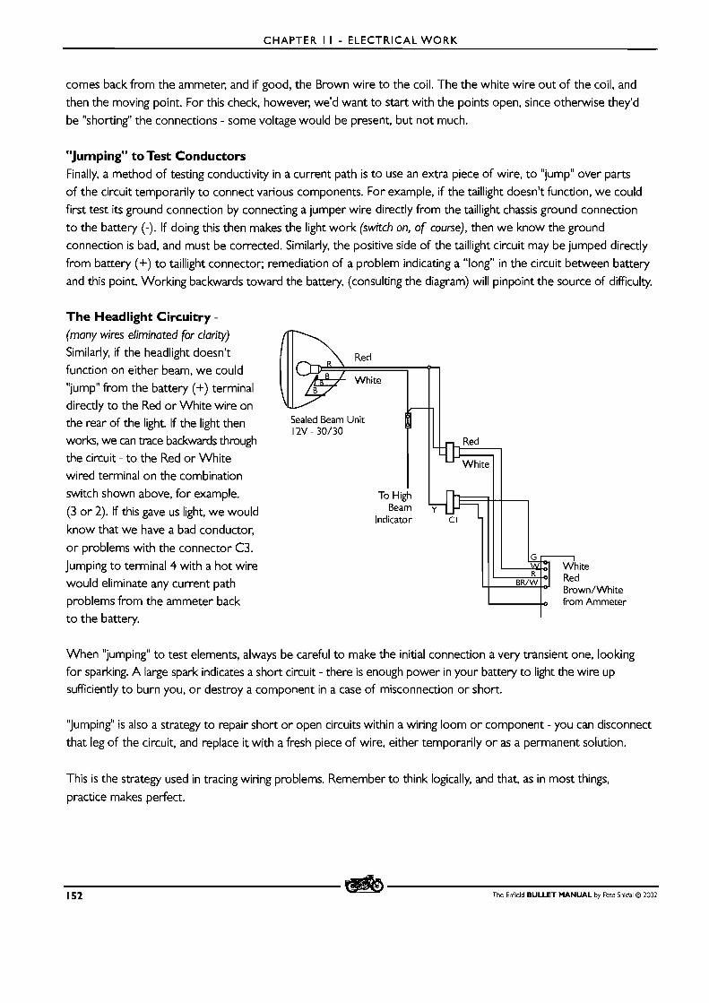
CHAPTER I I - ELECTRICAL WORK
comes back from the ammeter, and if good, the Brown wire to the coil. The the white wire out of the coil, and
then the moving point. For this check, however, we'd want to start with the points open, since otherwise they'd
be "shorting" the connections - some voltage would be present, but not much.
"Jumping" to Test Conductors Finally, a method of testing conductivity in a current path is to use an extra piece of wire, to "jump" over parts
of the circuit temporarily to connect various components. For example, if the taillight doesn't function, we could
first test i ts ground connection by connecting a jumper wire directly from the taillight chassis ground connection
to the battery (-). If doing this then makes the light work (switch on, of course), then we know the ground
connection is bad, and must be corrected. Similarly, the positive side of the taillight circuit may be jumped directly
from battery (+) to taillight connector; remediation of a problem indicating a "long" in the circuit between battery
and this point. Working backwards toward the battery, (consulting the diagram) will pinpoint the source of difficulty.
The Headlight Circuitry - (many wires eliminated for clarity)
Similarly, if the headlight doesn't
function on either beam, we could
"jump" from the battery (+) terminal directly to the Red or White wire on the rear of the light. If the light then
works, we can trace backwards through the circuit - to the Red or White
wired terminal on the combination
switch shown above, for example.
(3 or 2). If this gave us light, we would
know that we have a bad conductor,
or problems with the connector C3.
Jumping to terminal 4 with a hot wire
would eliminate any current path problems from the ammeter back
to the battery.
White
Brown/White
W from Ammeter
When "jumping" to test elements, always be careful to make the initial connection a very transient one, looking for sparking. A large spark indicates a short circuit - there is enough power in your battery to light the wire up sufficiently to burn you, or destroy a component in a case of misconnection or short.
'~umping" is also a strategy to repair short or open circuits within a wiring loom or component - you can disconnect
that leg of the circuit, and replace it with a fresh piece of wire, either temporarily or as a permanent solution.
This is the strategy used in tracing wiring problems. Remember to think logically, and that, as in most things,
practice makes perfect.
152 The Enfield BULLET M A N U A L by Pete Snidal O 2002
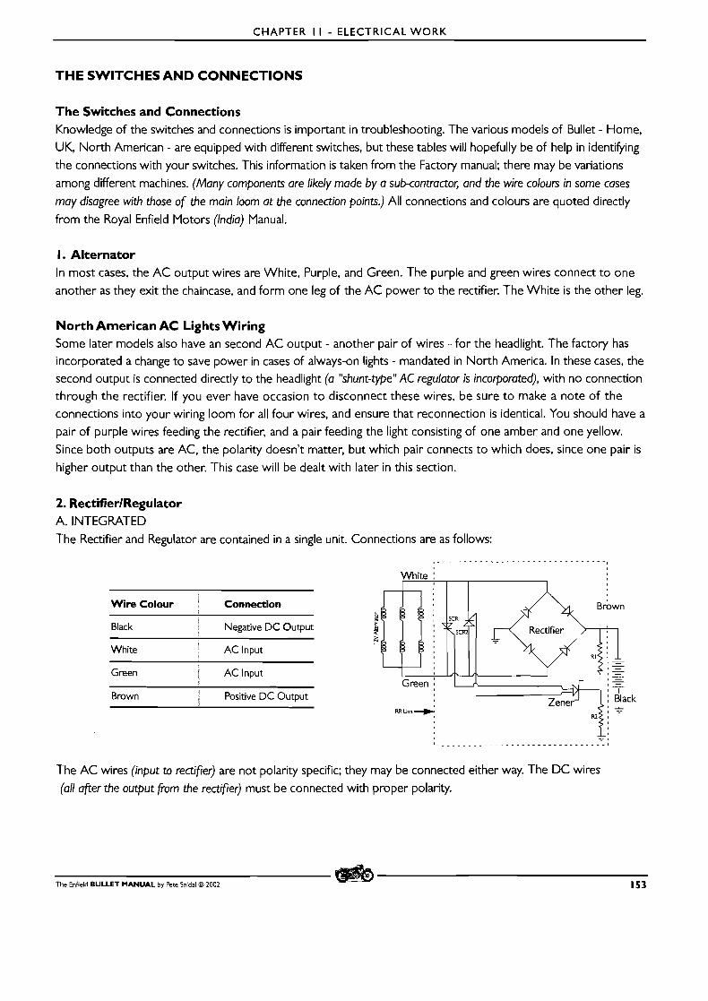
CHAPTER I I - ELECTRICAL W O R K
THE SWITCHES AND CONNECTIONS
The Switches and Connections Knowledge of the switches and connections is important in troubleshooting. The various models of Bullet - Home,
UK, North American - are equipped with different switches, but these tables will hopefully be of help in identifying
the connections with your switches. This information is taken from the Factory manual; there may be variations
among different machines. (Many components are likely made by a sub-contractor, and the wire colours in some cases
may disagree with those of the main loom at the connection points.) All connections and colours are quoted directly
from the Royal Enfield Motors (India) Manual.
I. Alternator In most cases, the AC output wires are White, Purple, and Green. The purple and green wires connect to one
another as they exit the chaincase, and form one leg of the AC power to the rectifier. The White is the other leg.
North American AC Lights Wiring Some later models also have an second AC output - another pair of wires - for the headlight. The factory has incorporated a change to save power in cases of always-on lights - mandated in North America. In these cases, the second output is connected directly to the headlight (a "shunt-type" AC regulator is incorporated), with no connection
through the rectifier. If you ever have occasion to disconnect these wires, be sure to make a note of the
connections into your wiring loom for all four wires, and ensure that reconnection is identical. You should have a
pair of purple wires feeding the rectifier, and a pair feeding the light consisting of one amber and one yellow.
Since both outputs are AC, the polarity doesn't matter, but which pair connects to which does, since one pair is
higher output than the other. This case will be dealt with later in this section.
2. RectifierlRegulator A. INTEGRATED
The Rectifier and Regulator are contained in a single unit. Connections are as follows:
White : I
Wire Colour Connection
Black Negative D C Output
White I AC lnput I
Green i : AC Input
Brown / Positive D C Output
6
Green j
RR Unn --).
The AC wires (input to rectifier) are not polarity specific; they may be connected either way. The DC wires
(all after the output from the rectifier) must be connected with proper polarity.
The Enfield BULLET MANUAL by Pete Snidal C3 2002 153
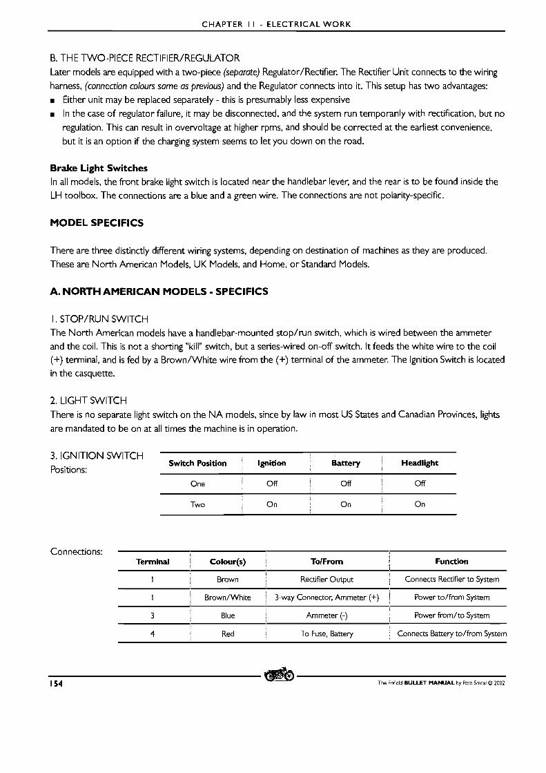
CHAPTER I I - ELECTRICAL W O R K
B. THE TWO-PIECE RECTIFIER/REGUMTOR
Later models are equipped with a two-piece (separate) Regulator/Rectifier. The Rectifier Unit connects to the wiring
harness, (connection colours same as previous) and the Regulator connects into it. This setup has two advantages:
Either unit may be replaced separately - this is presumably less expensive
In the case of regulator failure, it may be disconnected, and the system run temporarily with rectification, but no
regulation. This can result in overvoltage at higher rpms, and should be corrected at the earliest convenience,
but it is an option if the charging system seems to let you down on the road.
Brake Light Switches In all models, the front brake light switch is located near the handlebar lever, and the rear is to be found inside the
LH toolbox. The connections are a blue and a green wire. The connections are not polarity-specific.
MODEL SPECIFICS
There are three distinctly different wiring systems, depending on destination of machines as they are produced.
These are North American Models, UK Models, and Home, or Standard Models.
A. NORTH AMERICAN MODELS - SPECIFICS
I . STOP/RUN SWITCH The North American models have a handlebar-mounted stop/run switch, which is wired between the ammeter
and the coil. This is not a shorting "kill" switch, but a series-wired on-off switch. It feeds the white wire to the coil (+) terminal, and is fed by a Brown/White wire from the (+) terminal of the ammeter. The lgnition Switch is located
in the casquette.
2. LIGHT SWITCH
There is no separate light switch on the N A models, since by law in most US States and Canadian Provinces, lights
are mandated to be on at all times the machine is in operation.
3. IGNITION SWITCH Switch Position ' Ignition Battery Headlight
Positions:
One Off l Off S Off
i
On On 1
Two 1
On
Connections: Terminal Colour(s) + ToIFrom Function
1
I 2 Brown I Rectifier Output , Connects Rectifier to System
l Brown/White ! 3-way Connector, Ammeter (+) 1 Power to/from System I
3 Blue Ammeter (-) Power from/to System
4 i , Red To Fuse, Battery 1 Connects Battery to/from System
154 The Enfield BULLET MANUAL by Pete Snidal O 2002
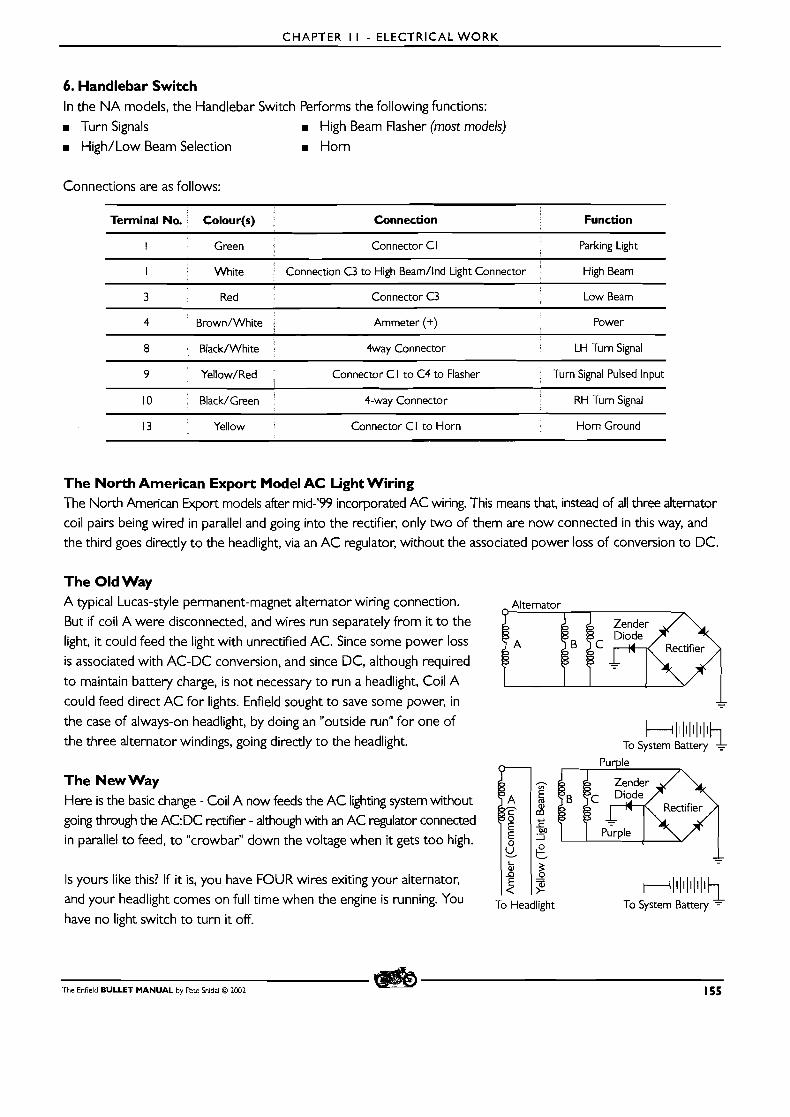
CHAPTER I I - ELECTRICAL W O R K
6. Handlebar Switch In the N A models, the Handlebar Switch Performs the following functions:
m Turn Signals High Beam Flasher (most models)
m High/Low Beam Selection m Horn
Connections are as follows:
>
Terminal No. Colour(s) Connection Function
l Green Connector C l Parking Light
I Wh~te Connection C3 to High Beam/lnd Light Connector High Beam I
3 Red Connector C3 Low Beam
4 Brown/White . Ammeter (+) Power I
8 Black/White 4way Connector LH Turn Signal
9 Yellow/Red Connector C I to C4 to Flasher Turn Signal Pulsed Input
10 Black/Green 4-way Connector : RH Turn Signal
13 Yellow Connector C l to Horn Horn Ground
The North American Export Model AC Light Wiring The North American kpo r t models after mid-'99 incorporated AC wiring. This means that, instead of all three alternator
coil pairs being wired in parallel and going into the rectifier, only two of them are now connected in this way, and
the third goes directly to the headlight, via an AC regulator, without the associated power loss of conversion to DC.
The Old Way A typical Lucas-style permanent-magnet alternator wiring connection.
But if coil A were disconnected, and wires run separately from it to the
light, it could feed the light with unrectified AC. Since some power loss
is associated with AC-DC conversion, and since DC, although required
to maintain battery charge, is not necessary to run a headlight, Coil A
could feed direct AC for lights. Enfield sought to save some power, in
the case of always-on headlight, by doing an "outside run" for one of
the three alternator windings, going directly to the headlight. clll1111111~
To System Battery ,
The New Way Here is the basic change - Coil A now feeds the AC lighting system without
going through the AC:DC rectifier - although with an AC regulator connected
in parallel to feed, to "crowbar" down the voltage when it gets too high.
Is yours like this? If it is, you have FOUR wires exiting your alternator,
and your headlight comes on full time when the engine is running. You To Headlight To System Battery = have no light switch to turn it off.
The Enfield BULLET MANUAL by Pete Snidal O 2002 155
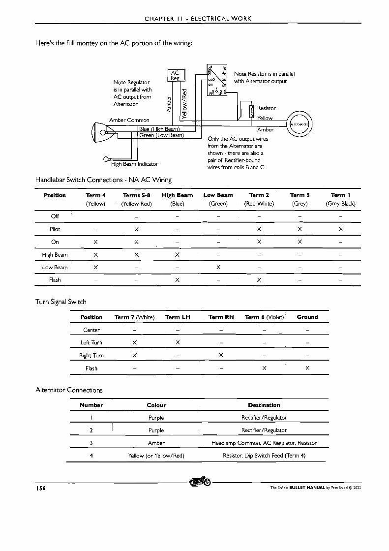
CHAPTER I I - ELECTRICAL W O R K
Here's the full montey on the AC portion of the wiring:
Note Resistor is in parallel Re
Note Regulator
from the Alternator are shown - there are also a pair of Rectifier-bound wires from coils B and C
Handlebar Switch Connections - NA AC Wiring
Position Term 4 Terms 5-8 High Beam Low Beam Term 2 Term 5 Term I
(Yellow) (Yellow-Red) (Blue) (Green) (Red-White) (Grey) (Grey-Black)
Pilot - X - - X X X
High Beam X X X - - - -
Low Beam X - - X - - -
Flash - - X - X - -
Turn Signal Switch
Position Term 7 (White) Term LH Term R H Term 6 (Violet) Ground
Left Turn X X - - -
Right Turn X - X - -
Flash - - X X -
Alternator Connections
Number ; Colour Destination
I Purple Rectifier/Re~ulator
2 Purple Rectifier/Regulator
3 Amber Headlamp Common, AC Regulator, Resistor
4 Yellow (or Yellow/Red) Resistor, Dip Switch Feed (Term 4)
156 The Enfield BULLET MANUAL by Pete Snidal O 2002
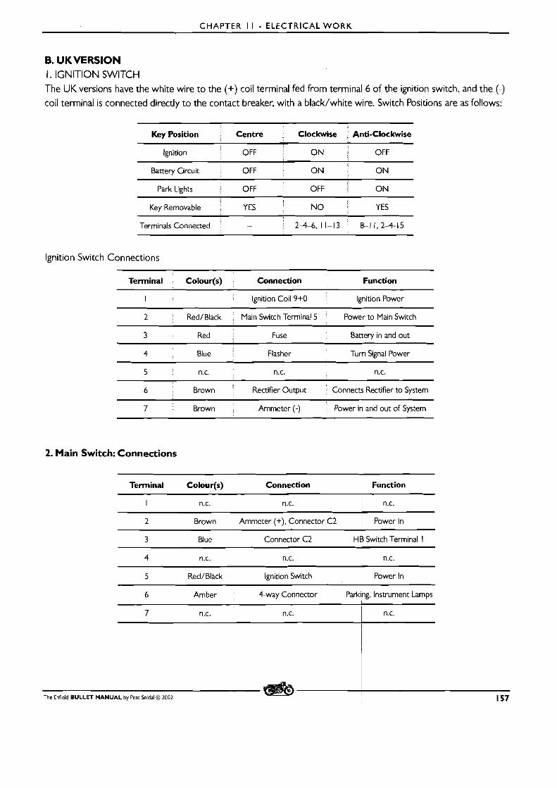
CHAPTER I I - ELECTRICAL W O R K
B. UKVERSION I. IGNITION SWITCH
The UK versions have the white wire to the (+) coil terminal fed from terminal 6 of the ignition switch, and the (-) coil terminal is connected directly to the contact breaker, with a black/white wire. Switch Positions are as follows:
I Key Removable i YES NO ! YES
Terminals Connected : - 1 2-4-6, 11-13 : 8-11,2-4-15
lgnition Switch Connections
Terminal Colour(s) Connection Function
I Ignition Coll 9+0 Ignition Power
2 Red/Black Maln Switch Terminal 5 Power to Maln Switch
3 Red Fuse Battery in and out i
4 Blue Flasher Turn Signal Power
5 n.c. n.c. n.c.
6 Brown Rectifier Output Connects Rectifier to System
7 Brown Ammeter (-) Power in and out of System
2. Main Switch: Connections
Terminal Colour(s) Connection Function
I n.c. n.c. 1 n.c.
2 Brown Ammeter (+). Connector C2 Power In
3 Blue Connector C2 H$ Switch Terminal I
5 Red/Black Ignition Switch power ln
6 Amber 4-way Connector ~ a r k i k . instrument amps
The Enfield BULLET MANUAL by Pete hidal C3 2002 l
157

CHAPTER I I - ELECTRICAL W O R K
3.The Handlebar Switch Terminal Number are those given in the factory manual
Terminal Colour(s) TolFrom Function
I Blue Main Terminal 3 Light Power In
2 White High Beam/lndicator Connector High Beam Power
3 Red Low Beam Low Beam Power
4 Brown Ammeter (+) Power
5 Yellow/Red Flasher Pulse Power In
6 Black/White Turn Signal Connector Left Turn Signal
10 Black/Green Turn Signal Connector Right Turn Signal
15 Yellow Horn Grounds Horn
16 Ground Ground Ground
C. HOME VERSIONS The regular (Home) versions feed the white wire coil (+) wire from the No. 4 terminal of the ignition switch. The Coil (-) connects to the Contact Breaker with a grey wire.
I . The ignition Switch - Connections
Terminal Wire Colour ; Connection Function
1 2 Brown i Through C I to Rectifier i Rectifier Output Connection to System
i > I
4 White i Through C I to Ignition Coil 1 Ignition Power S
6 Brown Through C I to Ammeter (-) i Connection to System - -
16 Red I C I to no further connection ; n.c. l
8 ' Green C I to no further connection 1 n.c. i l
S 12 ' B l a c k C l to no further connection 1 n.c.
10 : Red ? C2 to Fuse to Battery (+) 1 Power In
I 14 ] Brown Ammeter I Power
2. The Main Switch
2 1 Terminal ; Wire Colour Connection Function
i 1
f 2 Blue ! Handlebar Switch Terminal I (through snap connector) ; Power Input
Brown Ammeter (+) $ Power 2 i I
4 ; Green 3-way Connector 1 Pilot Bulbs, Park Lights
5 i
Amber ; 3-wat Connector, Connector C4 Tail, Instrument Lights I
158 The Enfield BULLET MANUAL by Pete Snidal O ZM)2

CHAPTER I I - ELECTRICAL WORK
3. The Handlebar Switch Connections - Handlebar Switch
1
Terminal i Colour .I Connection Function 4
pp
I Blue Through Snap Connector to Ma~n Switch Terminal 2 Power In?
a White , Through 4-way Connector to High Beam Indicator High Beam pp p p
3 ' Red Snap Connector to Headlamp Low Beam Output
4 ' Black/Green ' 4-way Connector Right Turn Signal
5 1 Yellow/Red . Snap Connector from Flasher l Pulsing Turn Signal Input
6 1 Black/White : 4-way Connector 1 Left Turn Signals 1
7 ' Yellow Snap Connector to Horn i Horn Ground
The Enfield BULLET MANUAL by Pete Snidal O 2002 159
CHAPTER 12 - PERFORMANCE MODIFICATIONS
CHAPTER 12 - PERFORMANCE MODIFICATIONS
MODIFYING FOR HIGHER PERFORMANCE
The first place to go when looking for performance is to ensure that your regular tuning is fully optimized. Ignition
timing, valve adjustment, and carburetor tuning are all covered elsewhere in this manual, and should always be kept
in perfect tune. As well, general engine condition is important - the improvement in sealing accomplished by a good
top end job - regrinding valves, decarbonizing, and replacing piston rings - can be counted on to make a significant
difference in an engine past its prime in these areas.
There are various stages of performance enhancements which may be done with the Enfield Bullet. It should be
borne in mind, however, that the these machines are not world-famous for their superior metallurgy, and that any
HP increase will inevitably result in subjecting the various parts of the engine to greater stress, particularly if the
extra available power is used a lot. I t should also be borne in mind that there is no "free lunch" - performance
enhancements invariably cost in tractability and general usefulness as well as in money; a "hot" motorcycle
requires more attention on the road, better fuel, and greater attention to being kept properly in tune than ever.
With this in mind, let's discuss performance tuning: There are three areas which may be improved; Volumetric.
Thermal, and Mechanical.
Volumetric Efficiency An internal combustion engine works on taking in air and fuel, burning them, and expelling the biproducts.
Improvements to Volumetric Efficiency will involve the intake and expulsion of gases. This can be done by modifying the Exhaust System, the Intake System, and the Cam Timing.
EXHAUST SYSTEM: Most beginners go to the exhaust system first. It is a fact that there is great psychological
satisfaction in making your motorcycle noisier; a noisier machine just feels more powerful! However, in the case
of the stock Indian-Made Bullet, it is also a fact that the as-comes (long) exhaust system is very restrictive, and
there is much room for improvement without getting too noisy. lmprovements in the neighborhood of 20% have
been documented on the dynamometer just by replacing the muffler with the shorter European-supplied model. These are available from your dealer. There is also a vast number of after-market exhaust options from which to
choose. Be careful, in the case of changing to a less restrictive exhaust system, to do a plug check and be prepared
to re-jet your carburetor for the change in requirements. You will almost certainly require richer jetting! See
Chapter 4 on carburetor adjustment. One last word: even on the Bullet, there is a law of diminishing returns
- it is not true that the noisier i t is, the more powerful it will be. Try not to make enemies of your neighbours
and/or friendly local law enforcement over the search for that last little bit of available power. And, when using
a less restrictive, and therefore noisier, exhaust system, remember to try not to twist the "loud handle" excessively in inappropriate places!
D The next stop on the search for Volumetric Efficiency is the Intake System. The standard air cleaner as supplied is also quite restrictive - at low throttle openings, this is not particularly important, but at higher openings it
becomes an important factor. Your choices are anywhere from no air filter at all to an aftermarket item, such as
a FiltronTM sock or more complicated option, or a K&NTM unit. (The No Filter option should only be considered if the machine is operated in dust-free conditions, but it is an option. It was common practice even for factories to supply
motorcycles without air filters as late as the late '50's.)
160 The Enfield BULLET MANUAL by Pete Snidal O 2002
CHAPTER 12 - PERFORMANCE MODIFICATIONS
m Another consideration is the stock EPA-approved crankcase breathing system. Cobbled on as an afterthought to
satisfy the US EPA requirements, it pretends to offer re-breathing of crankcase gasses, but the actual result is a
plugging of the stock air filter, resulting in rich burning unless the filter element, already restrictive, is replaced regularly. The solution: go back to original equipment with the "duckcall" crankcase breather, available from your
dealer. It is simply a short neoprene tube, flattened on one end to effect a one-way valve, which blows crankcase
gasses on the chain, acting as a chain lubricator. Another alternative is to use a piece of 3/8" (9mm) neoprene
tube, venting to the end of the rear fender, preferably through an automotive PCV valve, such as a IVeihoff PV25 I
placed somewhere in the line. If this option is chosen, the line should be blown out occasionally with compressed
air, and the PCV valve cleaned and checked. (Note: of course the valve must be connected so that gas flow is outward
from the engine.) m PORTING: the next step in improving VE is Porting - removing restrictions in the ports - the passages between the
valve seats and the carburetor or exhaust system. It should be borne in mind that changing the shape of the valve
ports is often counterproductive - removing metal should be done only by a competent shop with a "Flow Bench" to monitor their efforts. But removal of casting flashings, polishing and generally cleaning up the ports, and,
especially, matching carburetor, connecting tube, gaskets, etc to one another can result in significant improvements at high throttle opening.
Once the rest of the intake system has been optimized, further improvement can be made by "triple-cutting" the
valves and seats. In this technique, the valves are ground at three different angles, resulting in that last little edge in
gas flow. The three different small margins thus produced, of course, don't last as long between grindings as those done more conventionally.
m LARGER CARBURETOR: Newbies often flock to larger carbureton as a performance improver. It must be borne
in mind that the only possible effect of such a modification will be at throttle openings over full throttle with your present carburetor, and then will only provide an effect if the volumetric efficiency of your engine at
that time is such that the extra ability of your new carburetor to pass on more fuel-air mixture is usable. Furthermore, efficiencies of mixing fuel and air will be lower at lower (read: usable) throttle openings, since the carburetor's "step" below which efficiency falls will be higher. Consequently, a larger carburetor among the last steps in the search for speed, and certainly not the first.
m CAM TIPIII\IG: The final stop in the quest for VM is in the camshaft grinds and timing. Cams are set to open at
a certain position in the piston strokes, remain open for a certain number of degrees of crankshaft rotation, and to close at a second position. They also determine the amount of lift - the distance the valve opens off the valve seat.
These settings of duration and lift determine, to a vast extent, the power characteristics of the engine, such as
Power Band - the rpm range at which usable power is developed. The cam grinds in the stock Bullet have been
chosen to give a wide powerband developed at relatively low rpm. Cams can be found which will raise the
developed Horsepower at the cost of raising the powerband, - creating more honepower at higher rpm over a narrower rpm range - resulting in a racy, thoroughbred-like running - more gearchanging is required, more vibration
will be encountered at the higher rpms, and as a result reliability will suffer. But, combined as a part of a full schedule of other modifications mentioned here, "hi-race" cams can make an unmistakable improvement.
Thermal Efficiency Thermal Efficiency relates to how efficiently the fuel is burnt on the combustion stroke. How tightly it was compressed on the compression stroke is certainly a factor, and this is dependent on Compression Ratio - the ratio of combustion chamber volume at the bottom of the stroke to that at the top. A second factor is quality
The Enfield BULLET MANUAL by Pete Snidal O 2002 161
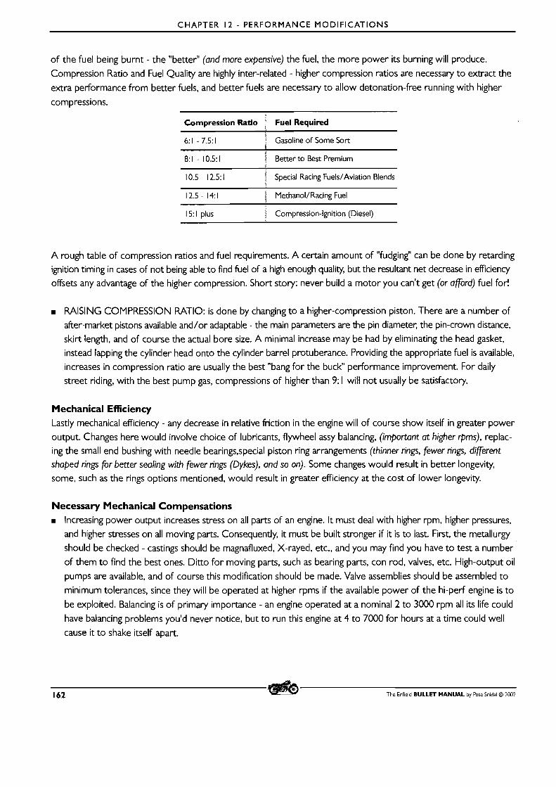
CHAPTER 12 - PERFORMANCE MODIFICATIONS
of the fuel being burnt - the "better" (and more expensive) the fuel, the more power its burning will produce.
Compression Ratio and Fuel Quality are highly inter-related - higher compression ratios are necessary to extract the
extra performance from better fuels, and better fuels are necessary to allow detonation-free running with higher
compressions.
Compression Ratio : Fuel Required
6: 1 - 7.5: 1 S Gasoline of Some Sort 1
8: 1 - 10.5: 1 i Better to Best Premium
10.5 - 12.5:l "pecial Racing Fuels/Aviation Blends i
12.5- 14:l i MethanoVRacing Fuel i
15: 1 plus ' Compression-Ignition (Diesel)
A rough table of compression ratios and fuel requirements. A certain amount of "fudging" can be done by retarding ignition timing in cases of not being able to find fuel of a high enough quality, but the resultant net decrease in efficiency
offsets any advantage of the higher compression. Short story: never build a motor you can't get (or afford) fuel for!
m RAISING COMPRESSION RATIO: is done by changing to a higher-compression piston. There are a number of
after-market pistons available and/or adaptable - the main parameters are the pin diameter, the pin-crown distance,
skirt length, and of course the actual bore size. A minimal increase may be had by eliminating the head gasket,
instead lapping the cylinder head onto the cylinder barrel protuberance. Providing the appropriate fuel is available,
increases in compression ratio are usually the best "bang for the buck" performance improvement. For daily
street riding, with the best pump gas, compressions of higher than 9: 1 will not usually be satisfactory.
Mechanical Efficiency Lastly mechanical efficiency - any decrease in relative friction in the engine will of course show itself in greater power
output. Changes here would involve choice of lubricants, flywheel assy balancing, (important at higher rpms), replac- ing the small end bushing with needle bearings,special piston ring arrangements (thinner rings, fewer rings, different shaped rings for better sealing with fewer rings (Dykes), and so on). Some changes would result in better longevity,
some, such as the rings options mentioned, would result in greater efficiency at the cost of lower longevity.
Necessary Mechanical Compensations Increasing power output increases stress on all parts of an engine. It must deal with higher rpm, higher pressures,
and higher stresses on all moving parts. Consequently, it must be built stronger if it is to last. First, the metallurgy
should be checked - castings should be magnafluxed, X-rayed, etc., and you may find you have to test a number
of them to find the best ones. Ditto for moving parts, such as bearing parts, con rod, valves, etc. High-output oil
pumps are available, and of course this modification should be made. Valve assemblies should be assembled to
minimum tolerances, since they will be operated at higher rpms if the available power of the hi-perf engine is to
be exploited. Balancing is of primary importance - an engine operated at a nominal 2 to 3000 rpm all i ts life could
have balancing problems you'd never notice, but to run this engine at 4 to 7000 for hours at a time could well
cause it to shake itself apart.
162 The Enfield BULLET MANUAL by Pete Snidal O 2002
CHAPTER 12 - PERFORMANCE MODIFICATIONS
WEAK POINTS: One possible weak point of the Enfield design can be the cork oil pressure feed seal. Especially
in a hi-perf engine, this should be checked even more regularly. Higher oil temperatures, particularly in the cylinder
head area, can be expected, and since this is already a potential weak spot - the oil pumped there has come from
the sump, fresh from having been through the engine - an oil cooler in the rocker feed line should be considered.
(This would have the added advantage of increasing oil capacity somewhat.) An air-cooled engine depends on a plentiful supply of cool, clean oil. The plain-bush big end is often a source of criticism; the more conventional
roller-bearing big ends are available in such as the AlphaTM kit, although if the unique Enfield plain-bush big end
has not yet proven itself, it never will. The basic Enfield design is unchanged from days of the famous 500 Fury,
which produced over 40 bhp, and these were not famously unreliable, so it is not unrealistic to expect a fairly highly-tuned Enfield to stay together if properly built and maintained.
Where Do I Get Performance Parts?
The most important part of the performance parts market, from the owner's point of view, is getting good
advice from a supplier with lots of experience with that which he is selling. Look around on the internet - the
royalenfield and bulletech yahoogroups are good places to start, and contact as many dealers as you can find. Ask
them specifically just how much experience they and/or their customers have had with various performance options, and satisfi yourself that you're not going to be their beta tester - unless of course this is your preference.
Unless you are highly experienced, performance testing is no place to be looking for discount suppliers with no inclination towards customer service.
The Enfield BULLET MANUAL by Pete Snidal O 2002 163

164 The Enfield BULLET MANUAL by Pete Snrdal O 2002
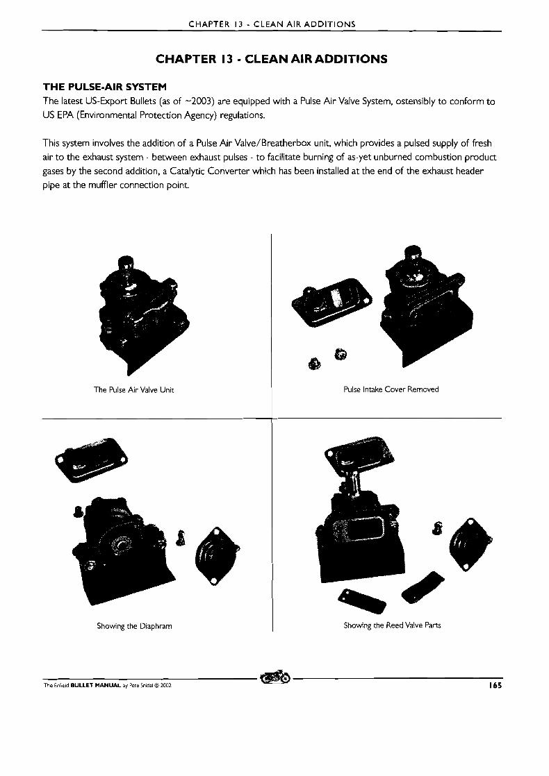
CHAPTER 13 - CLEAN AIR ADDIT IONS
CHAPTER 13 - CLEAN AIR ADDITIONS
T H E PULSE-AIR SYSTEM The latest US-Export Bullets (as of -2003) are equipped with a Pulse Air Valve System, ostensibly to conform to
US EPA (Environmental Protection Agency) regulations.
This system involves the addition of a Pulse Air Valve/Breatherbox unit, which provides a pulsed supply of fresh
air t o the exhaust system - between exhaust pulses - to facilitate burning of as-yet unburned combustion product
gases by the second addition, a Catalytic Converter which has been installed at the end of the exhaust header
pipe at the muffler connection point.
The Pulse Air Valve Unit Pulse Intake Cover Removed
Showing the Diaphram I Showing the Reed Valve Parts
The Enfield BULLET MANUAL by Pete Snidal O 1002 165
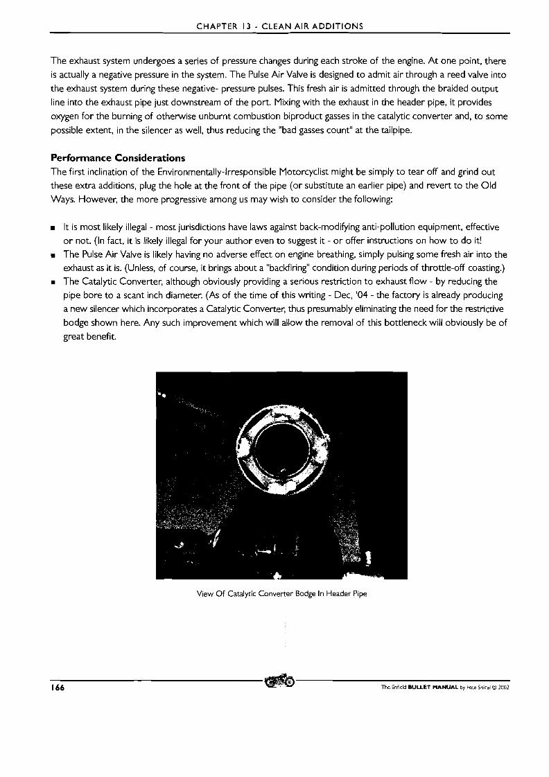
CHAPTER 13 - CLEAN AIR ADDITIONS
The exhaust system undergoes a series of pressure changes during each stroke of the engine. At one point, there is actually a negative pressure in the system. The Pulse Air Valve is designed to admit air through a reed valve into
the exhaust system during these negative- pressure pulses. This fresh air is admitted through the braided output line into the exhaust pipe just downstream of the port. Mixing with the exhaust in the header pipe, it provides
oxygen for the burning of otherwise unburnt combustion biproduct gasses in the catalytic converter and, to some
possible extent, in the silencer as well, thus reducing the "bad gasses count" at the tailpipe.
Performance Considerations The first inclination of the Environmentally-Irresponsible Motorcyclist might be simply to tear off and grind out
these extra additions, plug the hole at the front of the pipe (or substitute an earlier pipe) and revert to the Old Ways. However, the more progressive among us may wish to consider the following:
m I t is most likely illegal - most jurisdictions have laws against back-modifying anti-pollution equipment, effective
or not. (In fact, it is likely illegal for your author even to suggest it - or offer instructions on how to do it! M The Pulse Air Valve is likely having no adverse effect on engine breathing, simply pulsing some fresh air into the
exhaust as it is. (Unless, of course, it brings about a "backfiring" condition during periods of throttle-off coasting.) The Catalytic Converter, although obviously providing a serious restriction to exhaust flow - by reducing the
pipe bore to a scant inch diameter. (As of the time of this writing - Dec, '04 - the factory is already producing a new silencer which incorporates a Catalytic Converter, thus presumably eliminating the need for the restrictive
bodge shown here. Any such improvement which will allow the removal of this bottleneck will obviously be of great benefit.
View Of Catalytic Converter Bodge In Header Pipe
166 The Enfield BULLET MANUAL by Pete Snidal O 2002
CHAPTER 1 3 - CLEAN AIR ADDITIONS
Possible Improvements The system would undoubtedly be improved - both in terms of performance and pollution reduction - by being
replaced with an "outboard" cat converter of larger capacity. ie, I 1 /2" - or even greater - bore. Such a converter
may even cut down exhaust noise enough to replace the silencer. As well as the factory alternative - not currently
available in the North American market - there may well be an after-market Cat Converter/Silencer already on
the market. A little creative searching well may a clean-air alternative, combining combustion-product afterburning
with good gasflow as well. Thus total removal of this clean-air system addition is not recommended. l
THE CRANKCASE BREATHER CONDENSERTANK Beginning around Y2K, Enfield began equipping many models with a crankcase breathing system incorporating an "overflow" tank, connected between the crankcase breather fitting - on the left side of the crankcase casting just
below the cylinder barrel fins - and the carburetor air filter.
This tank is much maligned and misunderstood by many owners, since it does have one bad feature - if the factory- provided means of draining on a regular basis is not observed, it can become overfull with condensate, and this
liquid pollutant will be sucked into the air filter element, plugging the element. This will cause the machine to run
very rich, thus markedly increasing its contribution to air pollution from the engine exhaust, as well as bringing
about spark plug fouling and very poor performance.
The solution, however, is very simple: drain the liquid condensate, using the drain plug provided at the bottom of the tank, on a regular basis. Experience will tell you how often this should be done - it will vary with conditions of use and condition of your engine.
Don't Discard It! There is no real advantage to removing this condenser. It's function is to condense the blow-by gasses emitted
from the crankcase - the hot gasses will, when cooled, condense to a large degree into liquid, consisting mostly of water, with some petroleum distillate content as well. This should be disposed of with your used engine oil after
changes. The gasses which are not condensed back to liquid are vented from the tank into the air filter, where a
certain amount of engine suction draws them into the induction tract to be burnt with the fuel-air mixture pro-
duced by the carburetor. In gaseous form, this crankcase emission will do no harm, and in fact may increase your
fuel economy.
There is no harm done by this systerp. All automobiles produced since the early '60's have had a PCValve admitting
crankcase fumes into the air filter - they have to go somewhere, and they're notoriously greenhouse - considerably worse than exhaust fumes. Just as lohg as they're in gaseous form, they're no problem. Just as long as you keep
your condenser tank properly draindd, it will give you no trouble. O f course, the closer it gets to full, the less able
it is to do its proper job of cooling the crankcase fumes, so it should be maintained at a properly low level. Some
owners have had success with replacing the drain plug with a short piece of line and a valve of some kind - even a removable "cork" at the bottom woqld facllitate regular draining.
Excessive "Blow-By" l
As an engine wears, the piston ring gaps increase in size, and the piston/cylinder clearance increases. This wear
will increase "blow-by" of combustioh gasses past the piston into the crankcase. Hard use will create more blow-by
l
The Enfield BULLET MANUAL by Pete Snidal O 2002 167
CHAPTER 13 - CLEAN AIR ADDITIONS
than easy running, and in fact when conditions of use and wear are at a critical point, it can get bad enough actually
t o "cook" oil into the piston ring lands, reducing ring sealing, thus starting a spiral which soon ends in one or more
rings being frozen in their grooves, resulting in extreme blow-by.
As this situation develops (hopefully over many thousands of miles), the crankcase emissions increase. Thus an
engine getting close to i ts time for top overhaul may create such heavy crankcase emissions that the condenser can't handle them, and will pass on thick enough gas that the air cleaner will be getting polluted even if the con-
denser is in good (empty) condition. In this case, it may be necessary to disconnect the tank's outlet into the air cleaner (plugging the air cleaner end) t o admit the gasses directly to the atmosphere. This would be a "get you home" measure that should be resorted to only for a short time before attending to the real problem - excessive
blow-by due to broken ring(s), excessive top end clearance,etc.
168 The Enfield BULLET MANUAL by Pete Snidal O 2002
APPENDIX
A P P E N D I X
The Enfield BULLET MANUAL by Pete Snidal O 2002 169
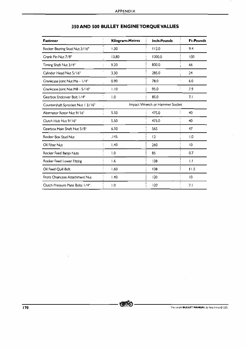
APPENDIX
350 AND 500 BULLET ENGINETORQUEVALUES
Fastener Kilogram-Metres Inch-Pounds Ft-Pounds
Rocker Bearing Stud Nut 3/ 16" 1.30 g 1 12.0 1 9.4
Crank Pin Nut 7 / 8 13.80 1200.0 100
T~ming Shaft Nut 3/4" 9.20 800.0 66 i
Cylinder Head Nut 5/ 16" 3.30 285.0 24 i
Crankcase Joint Nut M6 - 1 /4" 0.90 S 78.0 6.0
Crankcase Joint Nut M8 - 5/ 16" 1.10 1 95.0 7.9
Gearbox Endcover Bolt 1 /4" I .O 85.0 7.1
Countershaft Sprocket Nut 1 3/ 16" Impact Wrench or Hammer Socket
Alternator Rotor Nut 9/ 16" 5.50 475.0 40
Clutch Hub Nut 9/ 16" 5.50 ' 475.0 40
Gearbox Main Shaft Nut 5 / 8 6.50 , 565 47
Rocker Box Stud Nut ,145 12 I .O
Oil Filter Nut 1.40 ' 260 4 10 I
Rocker Feed Banjo Nuts I .O 8 5 0.7
Rocker Feed Lower Fitting 1.6 138 1.1
Oil Feed Quill Bolt I 1.60 138 11.5
Front Chaincase Attachment Nut 1.40 3 120 10 f
Clutch Pressure Plate Bolts 1 /4" 1
I .O 120 ; 7.1
1 70 The Enfield BULLET MANUAL by Pete Snidai O 2002
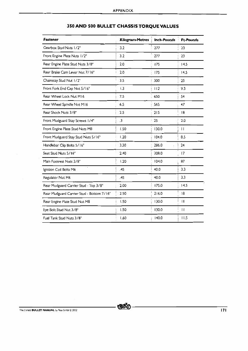
APPENDIX
350 AND 500 BULLET CHASSISTORQUEVALUES
Fastener Kilogram-Metres Inch-Pounds Ft-Pounds
Gearbox Stud Nuts 1 /2" 3.2 ' 277 . 23
Front Engine Plate Nuts 1 /2" a 3.2 277 23
Rear Engine Plate Stud Nuts 3/8" , 2.0 175 14.5
Rear Brake Cam Lever Nut 7/ 16" 2.0 175 14.5
Chainstay Stud Nut 1 / 2 3.5 300 25
Front Fork End Cap Nut 5/ 16" P
Rear Wheel Lock Nut M 16
Rear Wheel Spindle Nut M 16 6.5 565 47
Rear Shock Nuts 3 / 8 2.5 : 215 a 18
Front Mudguard Stay Screws 1 /4" i .3
Front Engine Plate Stud Nuts M8 U 1.50 130.0 I I
Front Mudguard Stay Stud Nuts 5/ 16" 1.20 104.0 8.5
Handlebar Clip Bolts 5 / 16" 3.30 286.0 V 24
Seat Stud Nuts 5/ 16" 2.40 a 208.0 g 17
Main Footrest Nuts 3/8" ' 1.20 104.0 87
Ignition Coil Bolts M6 l .45 ' 40.0 ! 3.3
Regulator Nut M6 I .45 40.0 ~ 3.3 P
--P
Rear Mudguard Carrier Stud - Top 3/8" 2.00 I 175.0 14.5
Rear Mudguard Carr~er Stud - Bottom 7/ 16" ' 2.50 2 1 6.0 ] 18 S
Rear Engine Plate Stud Nut M8 1.50 ; 130.0 : I I
Eye Bolt Stud Nut 3/8" 1.50 130.0 i I I
Fuel Tank Stud Nuts 3/8" 1.60 140.0 I 11.5
The Enfield BULLET MANUAL by Pete Snidal O 2002 171
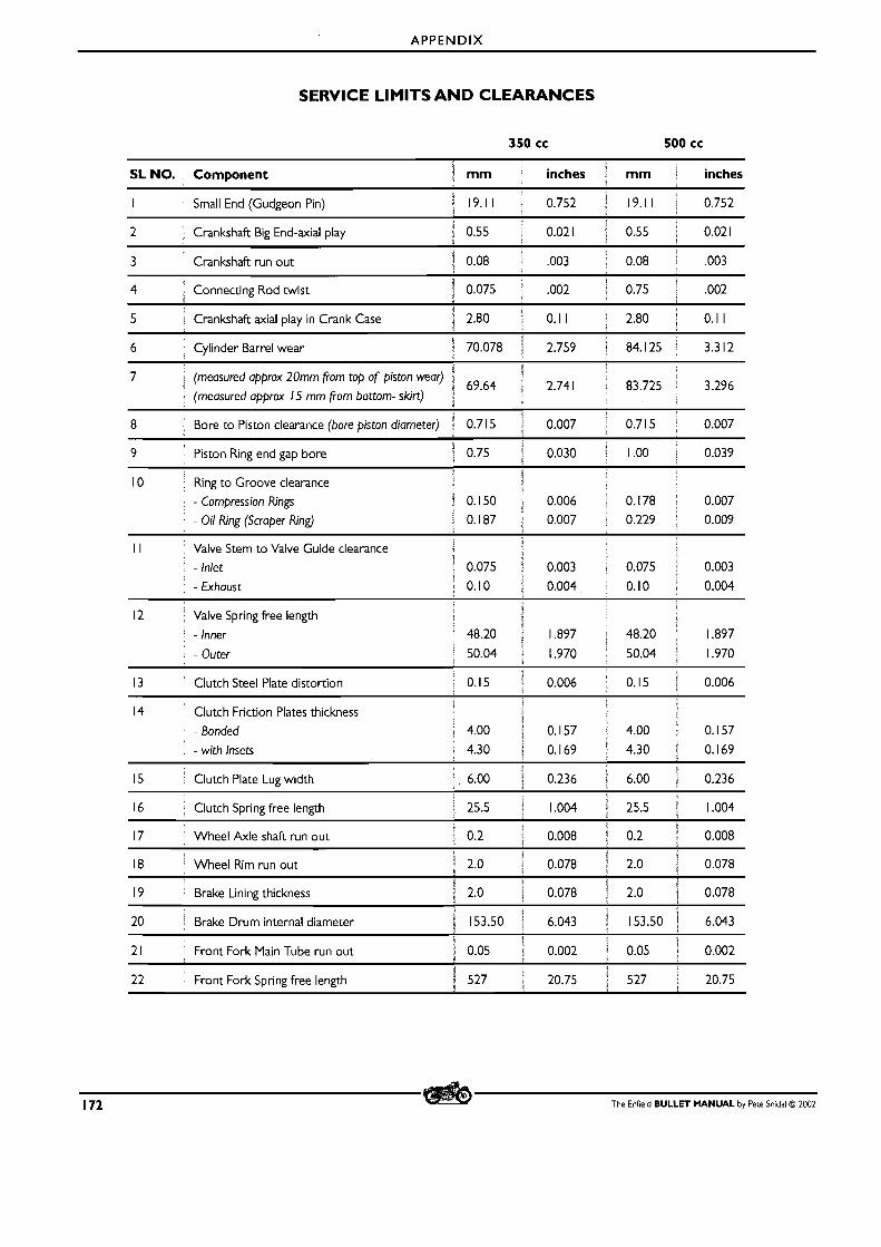
APPENDIX
SERVICE LIMITS A N D CLEARANCES
350 cc 500 cc
3 Crankshaft run out 0.08 i .003
4 Connecting Rod twist 0.075 .002 0.75 ,002
5 i
Crankshaft axial play in Crank Case , 2.80 0. I I S 2.80 j 0.1 I
6 Cylinder Barrel wear 70.078 p 2.759 84.125 1 3.3 12 l
7 (measured approx 20mm from top of piston wear) : 69.64 I 2.741 83.725 3.296 (measured approx 15 mm from bottom- skirt)
8 Bore to Piston clearance (bore piston diameter) 5 0.7 15 0.007 0.71 5 0.007
Ring to Groove clearance - compression Rings - Oil Ring (Scraper Ring)
lutch Steel Plate distortion
14 Clutch Friction Plates thickness
- Bonded
- with Insets
15 Clutch Plate Lug w~dth j 6.00 0.236 i 6.00 0.236
16 Clutch Spr~ng free length f 25.5 1.004 i 25.5 1.004 3
17 Wheel Axle shaft run out , 0.2 0.008 0.2 0.008
18 .; Wheel Rim run out ; 2.0 0.078 j 2.0 0.078 1
19 l
Brake Lining thickness i 2.0 0.078 2.0 0.078
20 ; Brake Drum internal diameter i 153.50 6.043 153.50 j 6.043
I 2 1 Front Fork Main Tube run out 1 0.05 0.002 1 0.05 1 0.002
#
22 Front Fork Spr~ng free length 527 1 20.75 527 20.75
172 The Enfield BULLET MANUAL by Pete Snidal O 2002
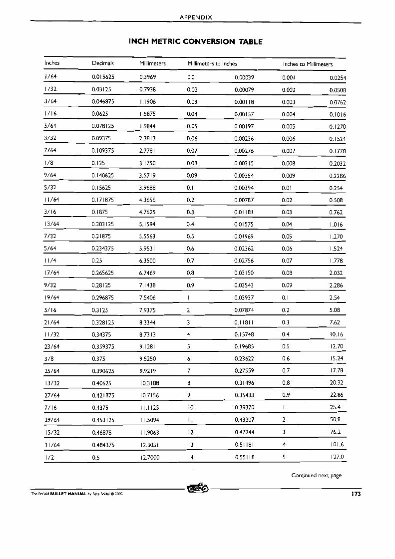
APPENDIX
INCH METRIC CONVERSION TABLE
Inches Decimals Millimeters Millimeters to Inches Inches to Millimeters
Continued next page
The Enfield BULLET MANUAL by Pete Snidal O 2002 173
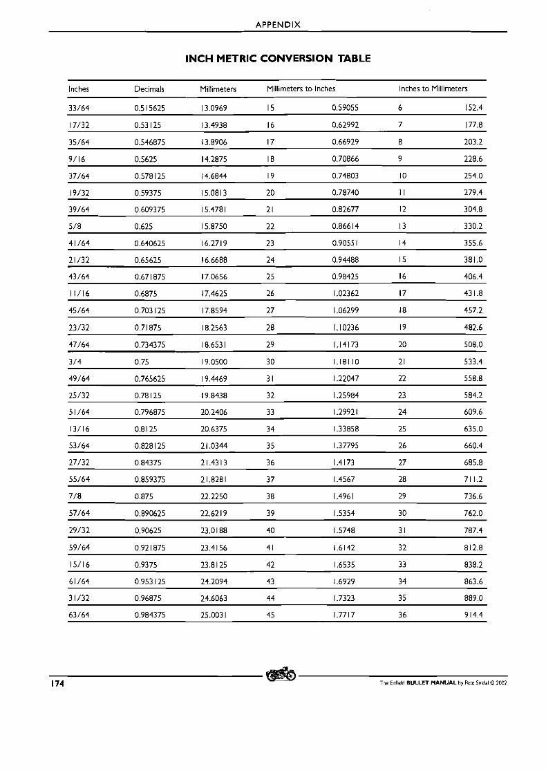
APPENDIX
INCH METRIC CONVERSION TABLE
Inches Decimals Millimeters Millimeters to Inches Inches to Millimeters
1 74 The Enfield BULLET MANUAL by Pete Snidal O 2002
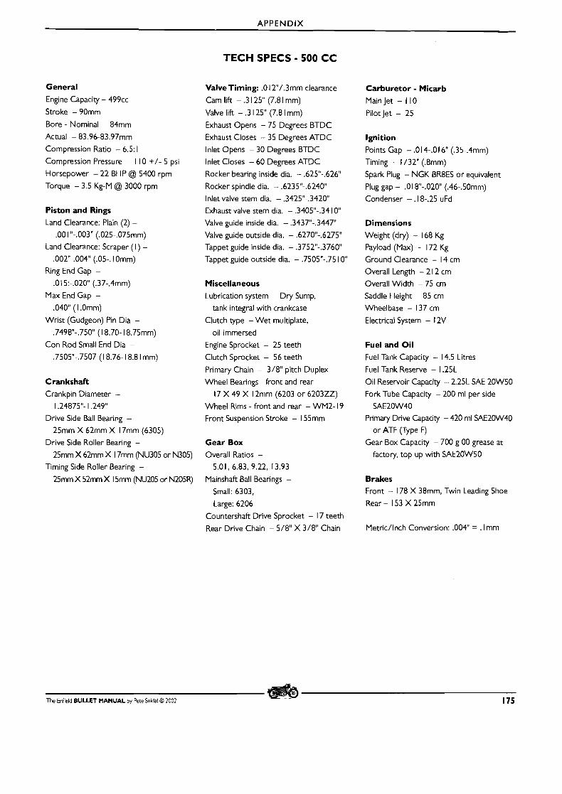
APPENDIX
TECH SPECS - 500 CC
General
Engine Capacity - 499cc
Stroke - 90mm
Bore - Nominal - 84mm
Actual - 83.96-83.97mm
Compression Ratio - 6.5: 1
Compression Pressure - I I0 +/- 5 psi
Horsepower - 22 BHP @ 5400 rpm
Torque - 3.5 Kg-M @ 3000 rpm
Piston and Rings
Land Clearance: Plain (2) -
.OO 1 "-.003" (.025-.075mm)
Land Clearance: Scraper ( I ) -
.002"-.004" (.05-. 1 Omm)
Ring End Gap -
.0 l 5:-.020 (.37-.4mm)
Max End Gap -
.04OU ( 1 .Omm)
Wrist (Gudgeon) Pin Dia -
.7498"-.750" (1 8.70- 18.75mm)
Con Rod Small End Dia -
.7505"-,7507 (1 8.76- 18.8 1 mm)
Crankshaft
Crankpin Diameter -
1.24875"- 1.249"
Drive Side Ball Bearing -
25mm X 62mm X 17mm (6305)
Drive Side Roller Bearing -
25mm X 62mm X 17mm (NU305 or N305)
Timing Side Roller Bearing -
25mm X 52mm X 15mm (NU205 or N205R)
ValveTiming: .O I2"/.3mm clearance
Cam lift - .3 125" (7.8 1 mm)
Valve lift - .3 125" (7.8 l mm)
Exhaust Opens - 75 Degrees BTDC
Exhaust Closes - 35 Degrees ATDC
lnlet Opens - 30 Degrees BTDC
lnlet Closes - 60 Degrees ATDC
Rocker bearing inside dia. - ,625"-.626"
Rocker spindle dia. - .6235"-.6240M
lnlet valve stem dia. - ,3425"-.3420
Exhaust valve stem dia. - .3405"-.34 IOU
Valve guide inside dia. - .3437"-.3447"
Valve guide outside dia. - .62701'-.6275"
Tappet guide inside dia. - .3752"-.3760
Tappet guide outside dia. - .7505"-.75 10"
Miscellaneous
Lubrication system - Dry Sump,
tank integral with crankcase
Clutch type -Wet multiplate,
oil immersed
Engine Sprocket - 25 teeth
Clutch Sprocket - 56 teeth
Primary Chain - 318" pitch Duplex
Wheel Bearings - front and rear
17 X 49 X 12mm (6203 or 620322)
Wheel Rims - front and rear - WM2- 19
Front Suspension Stroke - 155mm
Gear Box
Overall Ratios -
5.01, 6.83, 9.22, 13.93
Mainshaft Ball Bearings -
Small: 6303.
Large: 6206
Countershaft Drive Sprocket - 17 teeth
Rear Drive Chain - 5/8" X 318" Chain
Carburetor - Micarb
Main Jet - I I0
Pilotjet - 25
Ignition
Points Gap - .0 14-.0 16" (.35-.4mm)
Timing - 1 /32" (.8mm)
Spark Plug - NGK BR8ES or equivalent
Plug gap - .0 1 8"-.020 (.46-.50mm)
Condenser - .18-.25 uFd
Dimensions
Weight (dry) - 168 Kg
Payload (Max) - 172 Kg
Ground Clearance - 14 cm
Overall Length - 2 l 2 cm
Overall Width - 75 cm
Saddle Height - 85 cm
Wheelbase - 137 cm
Electrical System - 12V
Fuel and Oil Fuel Tank Capacity - 14.5 Litres
Fuel Tank Reserve - 1.25L
Oil Reservoir Capacity - 2.25L SAE 20W50
Fork Tube Capacity - 200 ml per side
SAE20W40
Primary Drive Capacity - 420 ml SAE20W40
or ATF vype F)
Gear Box Capacity - 700 g 00 grease at
factory, top up with SAE20W50
Brakes Front - 178 X 38mm, Twin Leading Shoe
Rear - 153 X 25mm
Metric/lnch Conversion: .004" = . l mm
The Enfield BULLET MANUAL by Pete Snidal O 2002 175
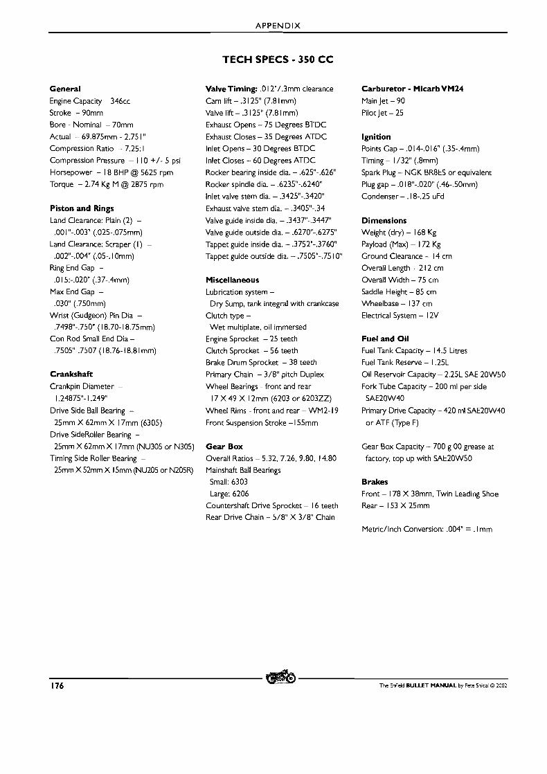
APPENDIX
TECH SPECS - 350 C C
General Engine Capacity - 346cc
Stroke - 90mm
Bore - Nominal - 70mm
Actual - 69.875mm - 2.75 1 " Compression Ratio - 7.25: 1
Compression Pressure - I I0 +/- 5 psi
Horsepower - I8 BHP @ 5625 rpm
Torque - 2.74 Kg-M @ 2875 rpm
Piston and Rings Land Clearance: Plain (2) -
.OO 1 "-.003" (.025-.075mm)
Land Clearance: Scraper ( l ) -
.002"-.004" (.05-. 1 Omm)
Ring End Gap -
.O 1 5:-.0201' (.37-.4mm)
Max End Gap -
.030" (.750mm)
Wrist (Gudgeon) Pin Dia -
.7498"-.750" (1 8.70- 18.75mm)
Con Rod Small End Dia -
.7505"-.7507 (1 8.76- 18.8 1 mm)
Crankshaft Crankpin Diameter -
1.24875"- 1.249"
Drive Side Ball Bearing -
25mm X 62mm X 17mm (6305)
Drive SideRoller Bearing -
25mm X 62mm X 17mm (NU305 or N305)
Timing Side Roller Bearing -
25mm X 52mm X 15mm (NU205 or N205R)
ValveTiming: .O I2"/.3mm clearance
Cam lift - .3 125" (7.8 1 mm)
Valve lift - .3 125" (7.8 1 mm)
Exhaust Opens - 75 Degrees BTDC
Exhaust Closes - 35 Degrees A-rDC
lnlet Opens - 30 Degrees BTDC
lnlet Closes - 60 Degrees ATDC
Rocker bearing inside dia. - .625"-.626"
Rocker spindle dia. - .6235"-.6240M
lnlet valve stem dia. - .3425"-.342OU
Exhaust valve stem dia. - .3405"-.34
Valve guide inside dia. - .3437"-.3447"
Valve guide outside dia. - .627OU-.6275"
Tappet guide inside dia. - ,3752"-.3760"
Tappet guide outside dia. - ,7505"-.75 10"
Miscellaneous Lubrication system -
Dry Sump, tank integral with crankcase
Clutch type -
Wet multiplate, oil immersed
Engine Sprocket - 25 teeth
Clutch Sprocket - 56 teeth
Brake Drum Sprocket - 38 teeth
Prirnary Chain - 3/8" pitch Duplex
Wheel Bearings - front and rear
17 X 49 X 12mm (6203 or 620322)
Wheel Rims - front and rear - WM2- 19
Front Suspension Stroke - 1 55mm
Gear Box Overall Ratios - 5.32, 7.26, 9.80, 14.80
Mainshaft Ball Bearings
Small: 6303
Large: 6206
Countershaft Drive Sprocket - 16 teeth
Rear Drive Chain - 5/8" X 3/8" Chain
Carburetor - MicarbVM24 Main Jet - 90
Pilot Jet - 25
Ignition Points Gap - .O 14-.0 16" (.35-.4mm)
Timing - 1 /32" (.8mm)
Spark Plug - NGK BR8ES or equivalent
Plug gap - .O 1 8"-.02OU (.46-.50mm)
Condenser - .18-.25 uFd
Dimensions Weight (dry) - 168 Kg
Payload (Max) - 172 Kg
Ground Clearance - 14 cm
Overall Length - 2 12 cm
Overall Width - 75 cm
Saddle Height - 85 cm
Wheelbase - 137 cm
Electrical System - 12V
Fuel and Oil Fuel Tank Capacity - 14.5 Litres
Fuel Tank Reserve - 1.25L
Oil Reservoir Capacity - 2.25L SAE 20W50
Fork Tube Capacity - 200 ml per side
SAE20W40
Prirnary Drive Capacity - 420 ml SAE20W40
or ATF (Type F)
Gear Box Capacity - 700 g 00 grease at
factory, top up with SAE20W50
Brakes Front - 178 X 38mm. Twin Leading Shoe
Rear - 153 X 25mm
Metric/lnch Conversion: .004" = . l mm
176 The Enfield BULLET MANUAL by Pete Snidal O 2002
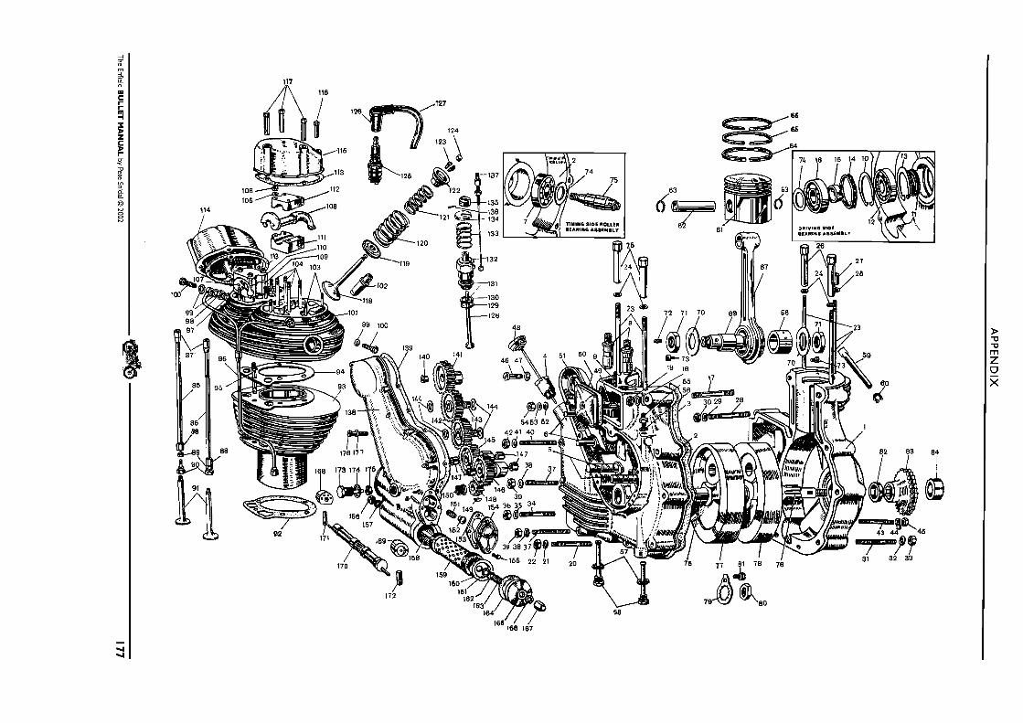
AP
PE
ND
IX
The Enf~eld BU
LL
ET
MA
NU
AL
by Pete Snidal O 2002
177
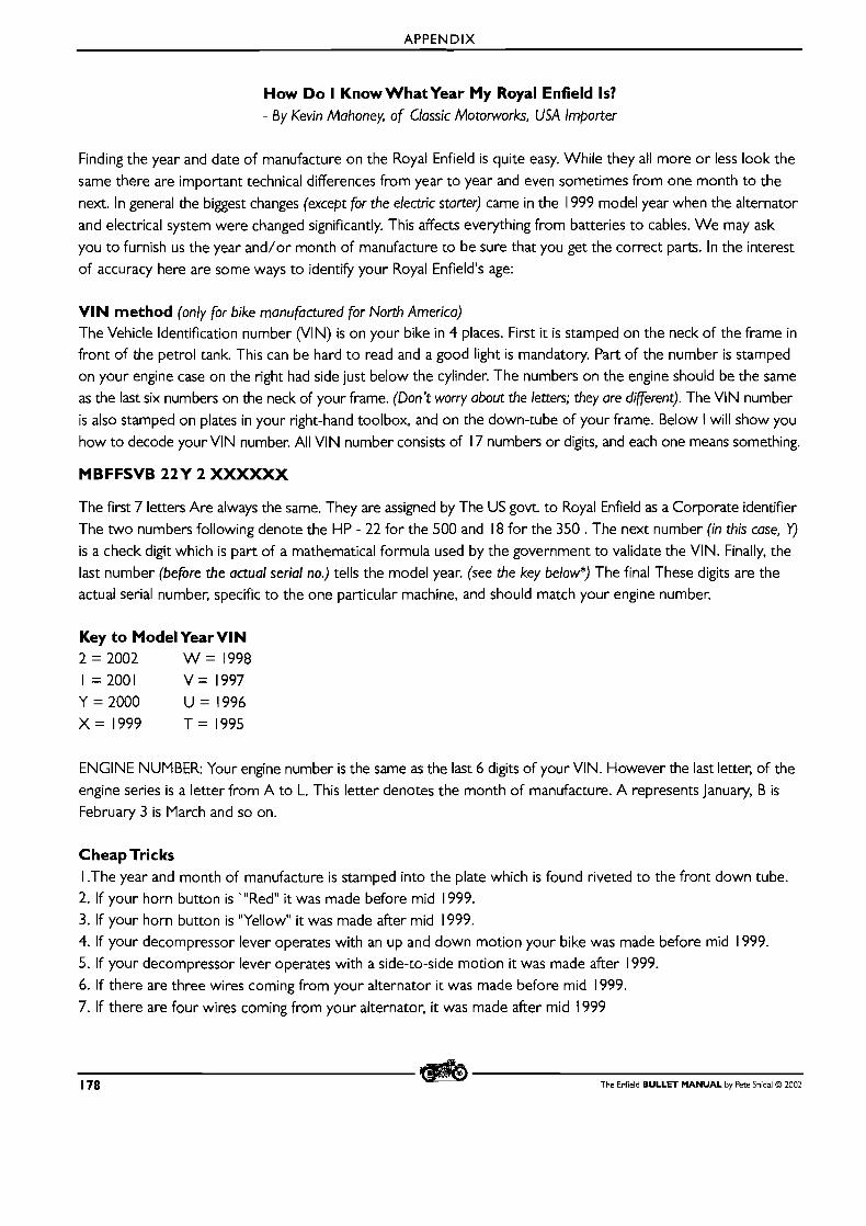
APPENDIX
How Do I Know What Year My Royal Enfield Is? - By Kevin Mahoney, of Classic Motorworks, USA Importer
Finding the year and date of manufacture on the Royal Enfield is quite easy. While they all more o r less look the same there are important technical differences from year to year and even sometimes from one month to the next. In general the biggest changes (except for the electric starter) came in the 1999 model year when the alternator and electrical system were changed significantly. This affects everything from batteries to cables. W e may ask you to furnish us the year and/or month of manufacture to be sure that you get the correct parts. In the interest of accuracy here are some ways to identify your Royal Enfield's age:
VIN method (only for bike manufactured for North America) The Vehicle Identification number (VIN) is on your bike in 4 places. First it is stamped on the neck of the frame in front of the petrol tank. This can be hard to read and a good light is mandatory. Part of the number is stamped on your engine case on the right had side just below the cylinder. The numbers on the engine should be the same as the last six numbers on the neck of your frame. (Don't worry about the letters; they are different). The VllV number is also stamped on plates in your right-hand toolbox, and on the down-tube of your frame. Below I will show you how to decode your VlN number. All VIN number consists of 17 numbers or digits, and each one means something.
MBFFSVB 22Y 2 XXXXXX
The first 7 letters Are always the same. They are assigned by The US govt. to Royal Enfield as a Corporate identifier The two numbers following denote the HP - 22 for the 500 and 18 for the 350 . The next number (in this case, Y) is a check digit which is part of a mathematical formula used by the government to validate the VIN. Finally, the last number (before the actual serial no.) tells the model year. (see the key below*) The final These digits are the actual serial number, specific to the one particular machine, and should match your engine number.
Key to Model Year Vl N 2 = 2002 W = 1998 I = 2001 V = 1997 Y = 2000 U = 1996 X = 1999 T = 1995
ENGINE NUMBER: Your engine number is the same as the last 6 digits of your VIN. However the last letter, of the engine series is a letter from A to L. This letter denotes the month of manufacture. A represents January, B is
February 3 is March and so on.
Cheap Tricks I .The year and month of manufacture is stamped into the plate which is found riveted to the front down tube. 2. If your horn button is '"Red" it was made before mid 1999. 3. If your horn button is "Yellow" it was made after mid 1999. 4. If your decompressor lever operates with an up and down motion your bike was made before mid 1999. 5. If your decompressor lever operates with a side-to-side motion it was made after 1999. 6. If there are three wires coming from your alternator i t was made before mid 1999.
7. If there are four wires coming from your alternator, it was made after mid 1999
178 The Enfield BULLET MANUAL by Pete Snidal O 2002
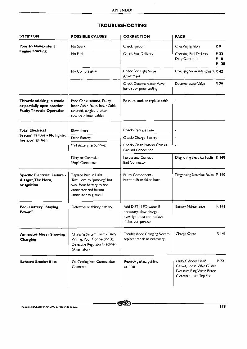
APPENDIX
TROUBLESHOOTING
SYMPTOM I POSSIBLE CAUSES I CORRECTION I PAGE
Poor to Nonexistent Engine Starting
No Spark
No Fuel
No Compression
Throttle sticking in whole or partially open position FaultyThrottle Operation
Check Decompressor Valve for dirt or poor sealing
Check Ignition
Check Fuel Delivery
Check For Tight Valve
Adjustment
Decompressor Valve P. 79
Total Electrical
Checking Ignition P. 9
Checking Fuel Delivery F! 22 Dirty Carburetor P. 10
P. 128
Checking Valve Adjustment F! 42
Poor Cable Routing, Faulty I Re-mute and/or replace cable
lnner Cable Faulty Inner Cable (snarled, tangled broken strands in inner cable)
System Failure - No lights, horn, or ignition
-
Blown Fuse Check/Replace Fuse
Bad Battery Grounding
I
Dirty or Corroded "Pop" Connector
Dead Battery
Check/Clean Battery Chassis Ground Connection
Bad Connector
Check/Charge Battery
Specific Electrical Failure - A Light,The Horn, or Ignition
1 -
Diagnosing Electrical Faults P. 140 Replace Bulb in Light, Test Horn by "jumping" hot wire from battery to hot connector and button connector to ground
Poor Battery "Staying Power,"
Faulty Component - burnt bulb or failed horn
Ammeter Never Showing Charging
Defective or thirsty battery
Exhaust Smoke: Blue
Add DISTILLED water if
necessary, slow-charge overnight, test and replace if situation persists
Charging System Fault - Faulty Wiring, Poor Connection(s),
Defective Regulator/Rectifier, (Alternator)
Battery Maintenance F! 141
Faulty Cylinder Head P. 72 Gasket, Loose Valve Guides, Excessive Ring Wear. Piston Clearance - see Top End
Troubleshoot Charging System, replace/repair as necessary
Oil Getting into Combustion Chamber
The Enfield BULLET MANUAL by Pete Snidal O 2002 179
Charge Check l? 141
Replace gasket, guides, or rings

APPENDIX
TROUBLESHOOTING continued
SYMPTOM I POSSIBLE CAUSES I CORRECTION I PAGE
Excessive Blue Smoke On Start-Up; goes away after running a few minutes
Wet-Sumping: - Oil is
accumulating in sump during standstill
Check Oil Seal Cork Gland, The Oilfeed Bush replace if necessary
Exhaust Smoke: Black Dirty Air Filter Clean or Replace Air Filter Element
Excessively Rich Fuel Mixture: Carburetion
Tune Carburetor Carburetor Adjustment P. 33
Excessive "Bluing" of Retarded Ignition Timing Advance Ignition Timing Adjusting Ignition Timing P. 38 exhaust pipe - more than
l
Mixture Too Rich Adjust Carburetor Carburetor Adjustment P. 33 10- 12"125-30cm of pipe discoloration l l l "Banging" in SilencerlMuffler
Excessively Lean Mixture: I Tune Carburetor I Carburetor Adjustment P. 33
Air Leak in Exhaust Pipe
Carburetion
Water In Fuel
Seal Pipe at Head with Hi-Temp Silicone, Check Muffler-Pipe Connection
Drain Tank and Floatbowl. Dry. Replace with fresh fuel
Grinding into I st Gear after starting
Poor Clutch Linkage Adjustment - Cable or Bellcrank
Adjust Clutch Linkage Adjusting the Clutch Linkage P. 23
oveprevs when pulling hard, re-synchronies when throttle is rolled back
Clutch Slipping - engine Dirty or oily plates, partially- collapsed clutch springs, worn friction disks
Remove and Inspect Clutch P. 103 - 105
I Poor Clutch Adjustment, 1
Poor Gear Changing - "popping" or "firing" out of gear, going into a neutral instead of the next gear
Inspect and Repair as Required I Adjusting the Clutch Linkage P. 23
Gearbox Shifter Mechanism Needs Adjusting
Adjust Shifter Mechanism Adjusting the Gear Change Mechanism P. 1 16 - 127
IMMEDIATELY back off on throttle, change to lower gear if necessary, correct poor ignition timing and/or carburetion ASAP
Adjusting the lgnition Timing P. 38 Engine Detonation - "Ping," or "Spark Knock" - occurs only under heavier loads and slower engine speeds
Excessive lgnition Advance
Mixture too lean DO NOT RUN with Detonation! Adjusting the Carburetor P. 33
Excessive Carbon ("coke" buildup in combustion chamber
Remove Cylinder Head and Decoke
Re & Re Cylinder Head P. 80 - 83
180 The Enfield BULLET MANUAL by Pete Snidal O 2002
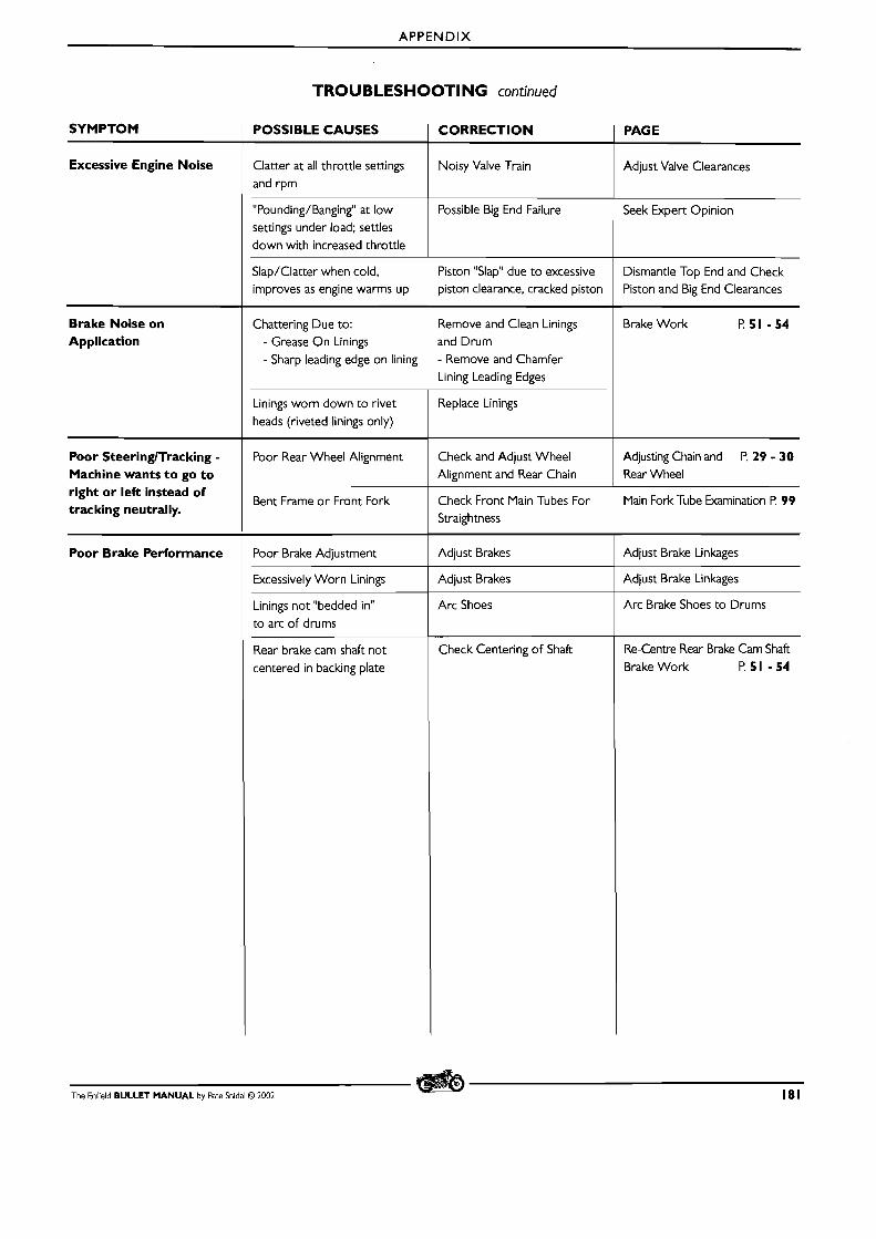
A P P E N D I X
TROUBLESHOOTING continued
The Enfield BULLET MANUAL by Pete Snidal O 2002 181
SYMPTOM
Excessive Engine Noise
Brake Noise on Application
Poor SteeringlTracking - Machine wants to go to right or let3 instead of tracking neutrally.
Poor Brake Performance
POSSIBLE CAUSES
Clatter at all throttle settings and rpm
"Pounding/Banging" at low settings under load; settles down with increased throttle
Slap/Clatter when cold. improves as engine warms up
Chattering Due to: - Grease O n Linings - Sharp leading edge on lining
Linings worn down to rivet heads (riveted linings only)
Poor Rear Wheel Alignment
Bent Frame o r Front Fork
Poor Brake Adjustment
Excessively Worn Linings
Linings not "bedded in" to arc o f drums
Rear brake cam shaft not centered in backing plate
CORRECTION
Noisy Valve Train
Possible Big End Failure
Piston "Slap" due t o excessive piston clearance, cracked piston
Remove and Clean Linings and Drum - Remove and Chamfer Lining Leading Edges
Replace Linings
Check and Adjust Wheel Alignment and Rear Chain
Check Front Main Tubes For Straightness
Adjust Brakes
Adjust Brakes
Arc Shoes
Check Centering o f Shaft
PAGE
Adjust Valve Clearances
Seek Expert Opinion
Dismantle Top End and Check Piston and Big End Clearances
Brake Work P51 -54
Adjusting Chain and P. 29 - 30 Rear Wheel
Main Fork-Tube Examination P. 99
Adjust Brake Linkages
Adjust Brake Linkages
Arc Brake Shoes to Drums
Re-Centre Rear Brake Cam Shaft Brake Work P.51 -54


![Enfield Bullet Workshop Manual 2000 2[1]](https://img.pdfslide.us/doc/110x75/577ce7541a28abf10394e27f/enfield-bullet-workshop-manual-2000-21.jpg)